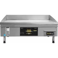
AccuSteam EGF2083B4850-T1 - Grill plate AccuTemp - Free user manual and instructions
Find the device manual for free AccuSteam EGF2083B4850-T1 AccuTemp in PDF.


| Product Type | Grill Plate |
| Brand | AccuTemp |
| Model | AccuSteam EGF2083B4850-T1 |
| Dimensions (L x W x H) | 30 x 20 x 5 inches |
| Weight | 35 lbs |
| Power Source | 120V, 60Hz |
| Wattage | 1800W |
| Cooking Surface Material | Stainless Steel |
| Cooking Area | 24 x 16 inches |
| Temperature Range | 200°F - 450°F |
| Temperature Control | Adjustable Thermostat |
| Indicator Light | Power and Ready Lights |
| Drip Tray | Removable, dishwasher safe |
| Non-Stick Coating | Yes, PTFE-free |
| Cleaning Instructions | Wipe with damp cloth; do not immerse |
| Automatic Shut-Off | Yes, after 60 minutes |
| Overheat Protection | Thermal fuse |
| Cool-Touch Handles | Yes |
| Non-Slip Feet | Yes |
| Cord Length | 6 feet |
| Material | Stainless Steel and Plastic |
| Warranty | 1 year limited |
| Certifications | ETL, NSF |
Frequently Asked Questions - AccuSteam EGF2083B4850-T1 AccuTemp
User questions about AccuSteam EGF2083B4850-T1 AccuTemp
0 question about this device. Answer the ones you know or ask your own.
Ask a new question about this device
Download the instructions for your Grill plate in PDF format for free! Find your manual AccuSteam EGF2083B4850-T1 - AccuTemp and take your electronic device back in hand. On this page are published all the documents necessary for the use of your device. AccuSteam EGF2083B4850-T1 by AccuTemp.
USER MANUAL AccuSteam EGF2083B4850-T1 AccuTemp
| Serial Number: | |
| Model: |

INSTALLATION/OPERATORS MANUAL ACCU-STEAM ELECTRIC G2 GRIDDLE
MODELS
EGF24A
EGF36A
EGF48A
EGF24B
EGF36B
EGF48B

natural_image
Exterior view of a stainless steel portable kitchen appliance with control buttons and legs (no visible text or symbols)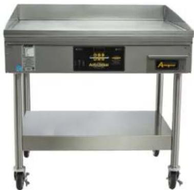
natural_image
Exterior view of a stainless steel multi-level kitchen appliance with wheels and control panel (no visible text or symbols)TABLE OF CONTENTS
| DESCRIPTION PAGE | |
| Table of Contents / Document History 1 | |
| Safety Warnings 2-5 | |
| General Info 6-7 | |
| Start up Form 8-10 | |
| Installation 11-13 | |
| Operation 14-24 | |
| Planned Maintenance 25 | |
| Service & Troubleshooting 26-27 | |
| Warranty Information 28-30 |
DOCUMENT HISTORY
| Current Revision | Date | Prior Revision | Date | Revision |
| MP5018-2002 | 02/03/2020 | MP5018-1912 | 12/16/2019 | Added stand installation instructions. |
1. WARNING SYMBOL DEFINITIONS
SYMBOL DEFINITIONS
Symbols are used to attract your attention to possible dangers. They are only effective if the operator uses proper accident prevention measures. Some of the symbols are boxed text; while others maybe just picture icons. Please give this information the respect they deserve for safe operation.
Symbol Icons
Below are definitions of the symbol icons used in this manual.

DANGER
Indicates an imminently hazardous situation; which, if unchanged, will result in death or serious injury.

CAUTION
Indicates a potentially hazardous situation; which, if unchanged, will result in minor or moderate injury.

NOTE
Advises the reader of information or instructions, vital to the operation or maintenance of the equipment.

CAUTION - HOT SURFACE

DANGEROUS VOLTAGE

EARTH GROUND
1.1 IMPORTANT FOR YOUR SAFETY
The safety instructions listed below on this page should be posted in a prominent location as a reminder of safe practices as well as recommended actions to follow in the event of an equipment or facility utility issue.
WARNING
In the event of a power failure, do not attempt to operate this appliance.
WARNING
Improper installation, adjustment, alteration, service or maintenance can cause property damage, injury or death. Read the installation, operating, and maintenance instructions thoroughly before installing or servicing this equipment.
WARNING
Only qualified service technicians/electricians should install this appliance to ensure that all electrical and safety requirements are met and that all wiring is installed in accordance with all national, state and local electrical codes.
1.2 WARNING & CAUTION NOTES
IMPORTANT: Read the following safety installation to avoid personal injury or death and to avoid damage to the equipment or property
⚠️ I=mproper installation, adjustment, alteration, service or maintenance can cause property damage, injury or death. Read the installation, operating and maintenance instructions thoroughly before installing or servicing the equipment.
Intended for other than household use.
Plug the appliance into a properly grounded electrical outlet of the correct voltage, size and plug configuration. If they do not match, contact a qualified electrician to determine the proper voltage and size and install the proper electrical outlet.
Do not connect to a circuit operating more than 150V to ground.
To avoid any personal injury or damage to the unit do not pull the appliance by the power cord.
To prevent any injury, discontinue any use if power cord is frayed or worn.
To prevent any injury or damage this commercial appliance must be installed by a qualified electrician.
To avoid any injury, turn the power off, unplug from the power source and allow to cool before performing any maintenance.
To avoid electrical shock or personal injury, do not steam clean or use excessive water on this commercial appliance.
This product has no "user" serviceable
parts. To avoid injury or damage to the commercial appliance use only Authorized AccuTemp Service Agents and Genuine Replacement Parts when service is required.
Genuine AccuTemp Replacement Parts are specified to operate safely in the environments in which they are used. Some aftermarket parts or generic replacements parts do not have the same specifications to operate safely in AccuTemp equipment. It is imperative that to use Genuine AccuTemp Replacement Parts to avoid injury or damage to the commercial appliance.
Always disconnect from power source before cleaning or servicing.
Any in-the-field modification that bypass the built-in safety features will result in personal injury or death.
This appliance must be properly grounded, in accordance with all National, State or local electrical codes.
This appliance has a totally unique design and is constructed unlike any other griddle on the market today. Any modification may permanently damage the appliance.
This appliance must be level for proper operation and to reduce possible damage to this commercial appliance.
This appliance is heavy, for safe handling, the installer should obtain help as needed or employ appropriate material handling equipment to remove the commercial appliance from the skid and move to the final location in the building.
⚠️ Temperatures in and around the appliance are very hot and can cause severe burns.
To avoid damage to the cooking surface of this appliance do not use abrasive cleaners such as a griddle stone or brick.
To avoid personal injury or damage to the appliance do not use a water jet to clean the unit.
To avoid damage to the appliance do not leave a chlorine sanitizer in contact with the stainless steel longer than 10 minutes.
To avoid severe burns slowly remove the grease tray to avoid spilling the contents. It is recommended to let it cool before removing.
To avoid damage to the appliance do not leave a chlorine sanitizer in contact with the stainless steel longer than 10 minutes.
2. General Information
2.1 Unit Specifications
| Accu-Steam Griddle Specifications (replace **** with voltage & phase, i.e. 2083) | ||||||
| Model # | EGF****A2450-T1EG | ****B2450-T1EGF****A3650-T1EGF****B3650-T1EGF****A4850-T1EGF****B4850-T1 | ||||
| KW Input | 9.6 kW 9.6 kW | 14.25 kW 14.25 kW | 14.25 kW 14.25 kW | |||
| 208/3 Amp Load | 27A / 9.6 kW | 27A / 9.6 kW 40A | 14.25 kW 40A / 14.25 kW | 40A / 14.25 kW | ||
| 240/1 Amp Load | 40A 40A n/a | n/a n/a n/a | ||||
| 240/3 Amp Load | 24A / 9.6 kW | 24A / 9.6 kW 34A | 14.25 kW 34A / 14.25 kW | 34A / 14.25 kW | ||
| 440/3 Amp Load | 14A / 11 kW | 14A / 11 kW | 21A / 16 kW | 21A / 16 kW | 21A / 16 kW | |
| 480/3 Amp Load | 16A / 13kW | 16A / 13kW | 23A / 19kW | 23A / 19kW | 23A / 19kW | |
| Unit Width (A) | 24.25 [616] | 24.25 [616] | 36.25 [921] | 36.25 [921] | 48.25 [1226] | 48.25 [1226] |
| Unit Depth (D) | 34.7 [881] | 28.7 [729] | 34.7 [881] | 28.7 [729] | 34.7 [881] | 28.7 [729] |
| Cooking Surface Width (B) | 23.9 [607] | 23.9 [607] | 35.9 [912] | 35.9 [912] | 47.9 [1217] | 47.9 [1217] |
| Cooking Surface Depth (C) | 30 [762] | 24 [610] | 30 [762] | 24 [610] | 30 [762] | 24 [610] |
| Depth to Rear Leg (E) | 8.5 [216] | 2.5 [64] | 8.5 [216] | 2.5 [64] | 8.5 [216] | 2.5 [64] |
| Center right to left (F) | 20 [508] | 20 [508] | 32 [813] | 32 [813] | 44 [1117] | 44 [1117] |
| Effective Cooking Area | 717 sq. in. | 574 sq. in. | 1077 sq. in. | 862 sq. in. | 1437 sq. in. | 1150 sq. in. |
| Grease Pan Capacity | 5 qt | 5 qt | 6 1/2 qt | 6 1/2 qt | 6 1/2 qt | 6 1/2 qt |
| NEMA Plug (208/240) | 15-50P | 15-50P | 15-50P | 15-50P | 15-50P | 15-50P |
| NEMA Plug (440/480) | L16-20P | L16-20P | L16-30P | L16-30P | L16-30P | L16-30P |

Fig 2.A

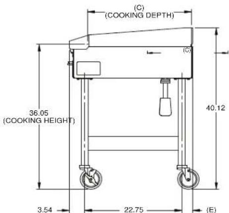
Fig 2.B
2.2 EQUIPMENT DATA PLATE
Model: AA B CCC D E FF GG
Example: EG F 120 1 A 48 50
A is the base model E = electric
B is the model configuration
CCC is the supply Voltage
D is the number of phases: 1 or 3
E is the depth
F is the width
G is the special configuration
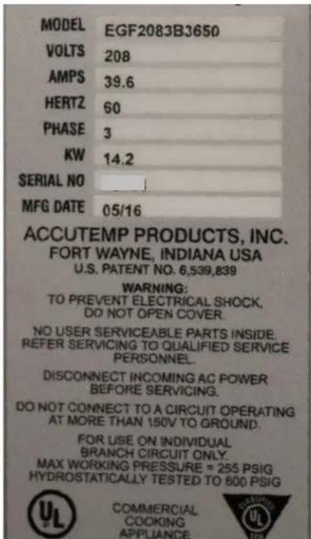
Fig 2.C
The Serial Number is also stamped into the upper right corner of the front plate, above the grease tray.
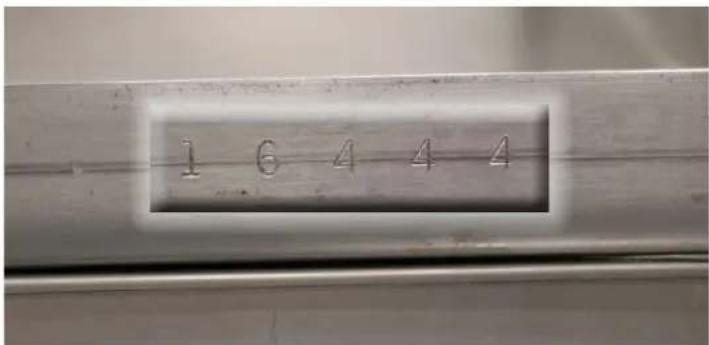
Fig 2.D

To register this AccuTemp product for warranty complete the following items:
- Complete the Installation/Operational Checklist and Warranty Registration Form on the following two pages.
- Mail, fax or scan and e-mail the form to AccuTemp Products, Inc to the contacts listed for each type on the form.
- OR use the following link and upload a copy of the Installation/Operational Checklist and Warranty Registration Form online: https://www.accutemp.net/warranty-registration/
If you have any questions about warranty registration please contact our technical service group. They are available 7 days a week from 7:00 am to 7:00 PM EST.
| Toll Free 800 480-0415 |
| Office 260 469-3040 |
| Fax 260 469-3045 |
| Email -Service service@accutemp.net |
| Email-Parts parts@accutemp.net |
| Web Site www.accutemp.net |
| SERIAL NUMBER: | MODEL NUMBER: | ||
| Location Name: | Date: | ||
| Street Address: | Service Company: | ||
| Street Address: | |||
| State/ Zip Code: | State/ Zip Code: | ||
| Building Name/#: | Service Phone #: | ||
| Contact Name: | Technicians Name: | ||
| Phone: | Technicians Email: | ||
| Email: | Additional Info: | ||
- AccuTemp Products, Inc. is not responsible for the installation and/or modifications to the electrical supply source.
- It is recommended that the wall receptacle be placed as low as State and Local codes allow. Placement in high heat zones will cause service issues that will not be covered under the product warranty.
THIS START-UP FORM MUST BE COMPLETELY FILLED OUT, EMAILED, FAXED OR MAILED OR EMAILED TO THE ACCUTEMP TECHNICAL & CUSTOMER SUPPORT DEPARTMENT, BEFORE THE WARRANTY IS ACTIVATED.
YES NO
| 1. Is the griddle level? (Tick Box) | ||
| 2. Is the wall receptacle positioned in a low heat zone? Note: It is recommended that the wall receptacle be placed as low as State & Local codes allow. Placement in high heat-zones will cause service issues that will not be covered under the product warranty. (Tick Box) | ||
| 3. If the griddle is mounted on a tabletop, have the (4) rubber foot tips been installed (Tick Box) | ||
| 4. Is the supply cord plugged into a wall outlet? (Tick Box) | ||
| 5. Is the supply cord being hardwired, without the plug, to a breaker box(if YES, be aware this voids the UL listing and may affect warranty. Tick Box) | ||
| 6. Is the supply cord properly connected to GND (Tick Box) | ||
| 7. What is the Electrical Breaker Amperage that will interrupt the Supply Voltage to the Unit: | ___AMPS | |
Confirm Supply Power Electrical Readings
Phase: Single φ Three φ
□
Supply Voltage: 208VAC 240VAC 440VAC 480VAC
□
Amperage Draw on each leg:
Single ____ WHT BLK
Three φ ____WHT ____BLK ____RED
ACCU-STEAM Electric Griddle Start-Up Form (continued)
YES NO
| 8. Is the correct NEMA Plug and Receptacle being used on the supply power cord?(Tick Box) |
| Type of NEMA Plug Tick One | |
| 15-50P (208/240V) | |
| L16-20P (440/480 24" MDL) | |
| L16-30P (440/480 36" & 48" MDL) |
Temperature Verification
| 1. What is the customers normal operating temperature for the Griddle? °F | |||
| 2. Using a weighted contact temperature probe with digital thermometer, does the surface temperature match the set temperature on the griddle controller? (Circle Y/N) | Y | N | |
| 3. Does the griddle heat light cycle ON/OFF once the surface temperature has met the set temperature? (Circle Y/N) | Y | N | |
4. Bring the griddle to 350°F and allow it to cycle twice. Take 9 temperatures across the surface of the unit in grid form and record (the temperatures should be consistent to ±10°F): 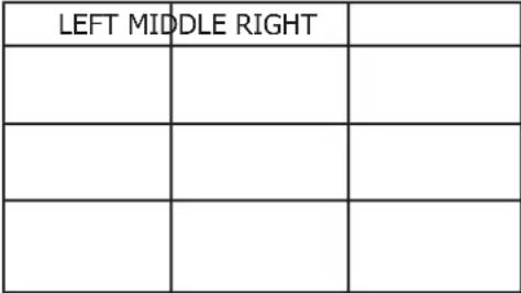 | |||
| 5. Does the unit operate correctly for 15 minutes after unit has reached temperature? (Circle Y/N) | Y | N | |
I accept this Start-up form as complete and accurate:
Signed: ____ Restaurant Management Date: ____/____/____
Print Name: ____
3. INSTALLATION
TABLE TOP/STAND MODEL
3.1 INSTALLATION NOTICE
Only qualified service technicians/electricians should perform the installation to ensure that all electrical and safety requirements are met and that all wiring installations are performed in accordance with all national, state and local codes.
TOOLS REQUIRED:
| Spirit Level |
| Phillips Screw Driver |
| Small Blade Straight Screw Driver |
| Digital Clamp Ammeter |
| Multimeter |
| Weighted Temperature Probe |
| Digital Temperature Meter |
3.2 UNPACKING
This appliance was carefully inspected before shipment from the factory. The transportation company assumes full responsibility for safe delivery to the customer until customer acceptance of the package. Careful inspection of the packaging and the appliance should be completed before acceptance from the transportation company.
3.3 GRIDDLE LIFTING
Steamers are heavy enough to require additional manpower or powered assistance when installing or moving the griddle.
When moving the equipment manually make sure there are enough people for the task as the equipment is heavy.
⚠️ Make sure the equipment is not dropped during moving. People doing the carrying could be seriously injured and/or the equipment damaged. The manufacturer does not accept any responsibility for damage resulted from such actions.
3.4 LOCATION AND PLACEMENT
The ACCU-STEAM ^™ electric appliance has been designed to be placed on a commercial kitchen counter-top, an AccuTemp griddle stand or directly onto any flat, non combustible level surface that will support the appliance weight.
The operating temperature ranges from 200^ -400°F ( 93^ -204°C). Since these temperatures can also be found on surfaces around the perimeter of this commercial appliance, care should be given not to install next to or against, objects or surfaces with a low melting or flash point.
3.5 CLEARANCES
| Location | Combustible Construction | Non-Combustible Construction |
| Back | 2 Inches 0 inches | |
| Right Side | 1 Inch 0 inches | |
| Left Side | 1 inch 0 inches | |
| SUITABLE FOR ALL INSTALLATION ON COMBUSTIBLE FLOORS. | ||
3.6 LEVELING
The appliance must be installed in a level condition. An out-of-level condition may cause uneven temperatures and in a severe out of level condition damage to the appliance can occur. Use a spirit level resting on the appliance cooking surface to ensure it is level front-to-back and left-to-right.
3.7 TABLE TOP
Install the (4) rubber foot tips provided with your appliance onto the four foot adjusters of each of the commercial appliance legs. This will keep the griddle from sliding on the counter-top under normal use. Once the rubber foot tips have been installed, adjust the four foot adjusters up or down as needed to level the griddle side to side and front to back
AccuTemp STAND
If mounted to an AccuTemp griddle stand with casters, ensure that the floor surface is level and place the two locking casters to the "on" position and follow the leveling instructions to verify the appliance is level.
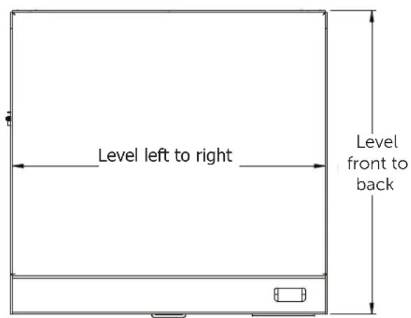
Fig 3.A top down view of griddle
3.8 STAND INSTALLATION
⚠️Improper installation, adjustment, alteration, maintenance or service can cause death or injury or property damage. Read the installation instructions completely before installing, maintaining or servicing this accessory.
⚠️ Use of any replacement parts other than those supplied by AccuTemp Products may cause bodily injury, damage to property, and damage to the equipment. Use of non OEM parts will void all active warranties.
Do not touch this accessory while running as the outside will be hot and can cause a burn injury. Always wait until the accessory is cool before servicing.
⚠ Griddles that mount to the this accessory are heavy enough to require additional people or powered assistance when installing. Failure to do so can cause injury or death.
Operation of this accessory in an out of level condition could cause poor performance of the griddle that is mounted to it.
TOOLS REQUIRED:
| Lifting device that is rated for lifting a minimum of 500 pounds to a minimum height of 26 inches |
| 7/16" combination wrench |
| Inch pound torque wrench and 7/16" socket |
| 1" Open end wrench or Adjustable wrench |
| Level |
- Carefully remove the packing material of the stand.
- Locate the stand in an area where there is room to work around If the stand model has casters lock the front casters to the on position (Fig 3.B).
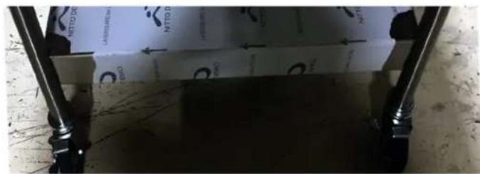
Fig 3.B
- Using the lifting device make sure that the plate or forks extend the width of the griddle bottom to avoid damaging the griddle (Fig 3.C).

natural_image
Exterior view of a transparent rectangular enclosure with small black components and a small cable attached (no visible text or symbols)Fig 3.C
- Raise the lifting device enough to gain access to the four shipping legs (Fig 3.D).

natural_image
Exterior view of a large industrial machine or enclosure with metal components and structural supports (no visible text or symbols)Fig 3.D
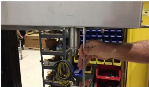
- Remove the two fasteners that attach each of the four legs to the griddle and retain the fasteners for later use (Fig 3.E).
natural_image
Close-up of hands installing or adjusting a mechanical assembly with blue and yellow components (no visible text or symbols)Fig 3.E
- Raise the lifting device so that the griddle clears the mounting tabs of the stand (Fig 3.F). Align the holes in the four mounting tabs of the stand to the threaded holes of the griddle.
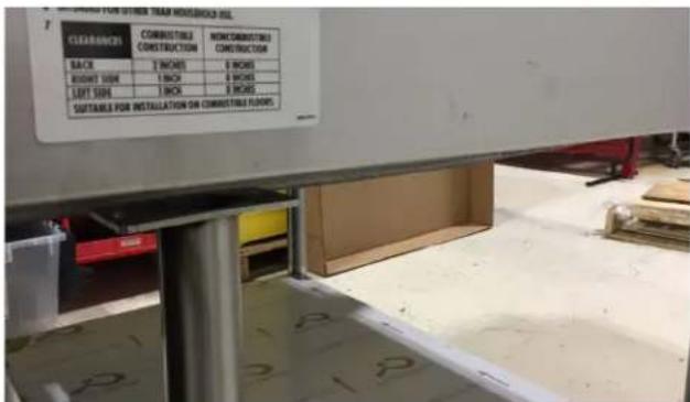
Fig 3.F
- Locate the eight fasteners and lock washers removed in step 6. Place a split lockwasher on each bolt and push through the hole in the mounting tab (2 holes per mounting tab) and hand thread each into the griddle's threaded holes. Verify that the fasteners are not cross threaded (Fig 3.G).

natural_image
Close-up of a mechanical assembly with a metallic cylindrical component and yellow warning boxes (no visible text or symbols)Fig 3.G
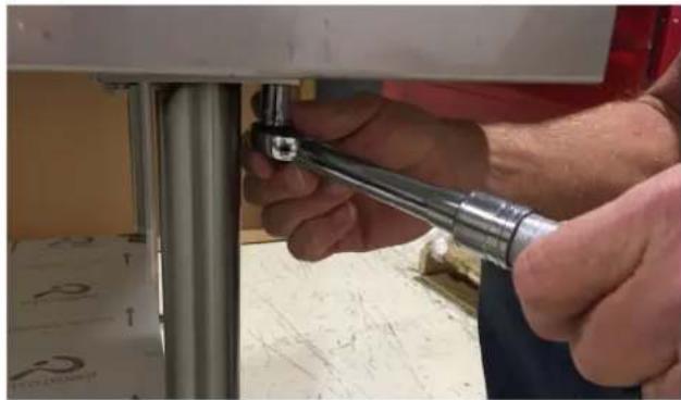
- Tighten each fastener to 75 inch pounds (Fig 3.H).
natural_image
Close-up of hands adjusting a metal pipe fitting on a mechanical fixture (no visible text or symbols)Fig 3.H
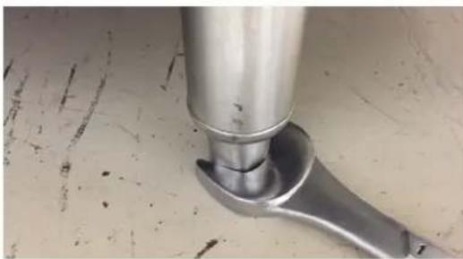
- Stands with adjustable feet: Level the griddle using the adjustable feet from front to back and side to side by using a 1" open end wrench or adjustable wrench and turn each foot clockwise to raise and counter clockwise to lower (Fig 3.1).
natural_image
Close-up of a metallic mechanical component with a handle and central shaft, resting on a textured surface (no text or symbols visible)Fig 3.1
Stands with casters: If the stand is fitted with casters they can not be adjusted and the floor must be level.
This accessory carries a one year parts only warranty for manufacturing defects.
3.9 ELECTRICAL CONNECTIONS
When this appliance is installed with casters it must be installed with the casters supplied. A connector complying with either ANSI Z21.69 - CSA 6.9. It must also be installed with restraining means to the connector as specified in the appliance manufacturer's instructions.
This commercial appliance must be properly grounded in accordance of all current National, state and local codes. Never remove the ground prong of the plug.
3.9.1 ELECTRICAL SUPPLY
The electrical voltage requirement is listed on the data plate that is located on the lower left side panel.
All AccuTemp Accu-Steam Electric Griddles are supplied with a power cord and plug that must be connected to the specified receptacle.
Make sure the voltage is within 10% of the voltage listed on the griddle data plate
⚠️ Connection to any other voltage not identified on the data plate will cause damage to the components and is not coveredunder warranty.
⚠️ Grounding provides a path for electric current to reduce risk of shock.
This product is equipped with a power cord having a grounding plug. If plug is removed or hard wired, UL approval is lost.
The plug must be plugged into a receptacle that is properly installed and grounded in accordance with all National, State and local electrical codes or in the absence of local electrical codes with the National Electric Code, ANSI/NFPA 70, or the Canadian Code, CSA C22.2 as applicable.
Under no circumstances shall the plugs grounding prong be cut or bent to fit a receptacle other than the one specified.
Do not use any adapters.
⚠️ Any in-field modification made that bypass the safety features of this appliance will result in serious injury or death.
Any in-field modifications made without written authorization from AccuTemp Products, Inc. will void all written and oral warranties.
The ACCU-STEAM™ griddle has been designed, manufactured and tested to meet or exceed the demanding standards of safety set forth by ANSI/NFPA 70. To ensure that this high level of safety is maintained in your installation, it is important that you read and understand the following information before attempting to plug in your griddle.
3.9.2 ELECTRICAL REQUIREMENTS
Electrical requirements are listed on the data plate located on the front right of the control panel. All standard AccuTemp griddles are supplied with a 6ft (1.83m) cord and the appropriate UL listed plug that must be connected to the correct voltage specified on the units data tag. Depending on the rating listed on the data plate. Make sure that the voltage at your supply receptacle is within ± 10 % of the voltage listed on the griddle data plate. Connection to any other voltage may cause damage to components in the commercial appliance. The appliance plug must be used with the appropriate receptacle.
3.9.3 GROUNDING INSTRUCTIONS
Grounding provides a path for electric current to reduce the risk of shock. This product is equipped with a power cord having a grounding conductor and a grounding plug. The plug must be plugged into a grounded receptacle that is installed and grounded in accordance with local codes, or in the absence of local codes, with the National Electric Code, NFPA 70, or the Canadian Electrical Code, CSA22.2, as applicable.

natural_image
Simple electrical circuit symbol for a three-pin inductor (no text or labels)NEMA 6-50R
240V Single Phase

natural_image
Simple electrical socket symbol with three U-shaped pins and two I labels (no text or numbers)NEMA 15-50R 208/240V 3 Phase

NEMA L16-30R
440/480V 3 Phase
Fig 3.J
4. OPERATION
RISKS RESULTING FROM CONTACT WITH VERY HOT OBJECT:
HOT
Hot areas may form during the cooking process, especially on the cookware, grills and the inner side of the door. Use protective gloves whenever handling hot objects. During the cooking process, do not handle cookware containing liquids or liquid foodstuffs located above eye level. Danger of burns.
Be sure all operators read, understand and follow the information contained in this manual including caution warnings, operating instructions and safety instructions.
Never use wet or damp gloves as moisture can conduct heat quickly.
Keep the floor in front of the equipment clean and dry. If spills occur, clean immediately to avoid potential injuries.
Do not use abrasive (or steel) materials, such as wire brushes, metal scouring pads to clean the griddle surface
The ACCU-STEAM G2™ griddle is constructed and uses technology like no other griddle in the world. The stainless steel cooking surface is heated by steam. The griddle steam chamber requires no additional liquid or maintenance. A temperature sensor to sense temperature and an over-temperature safety shutdown system are part of the griddle assembly. At temperatures below 212°F (100°C), the chamber is actually in a vacuum, similar to that of a canning jar. At temperatures above 212°F (100°C), the chamber operates under pressure. The temperature sensor senses the temperature of the steam and reports this data to the temperature control electronics, which energizes the heating system. This system maintains the griddle cooking surface temperatures to within ± 5°F (2.7°C) over the entire cooking surface and provides a near instant temperature recovery, even in the same spot on the griddle, when turning food in place.

natural_image
Technical illustration of a structural beam with an inset close-up showing internal components (no text or symbols)Fig 4.A
4.2 VISUAL IDENTIFICATION
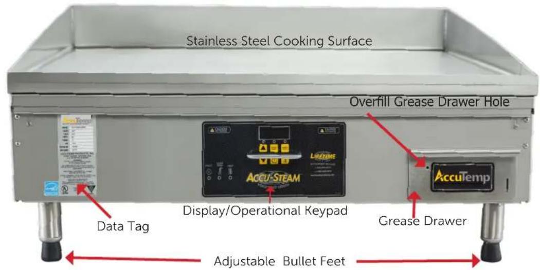
Fig 4.B

Fig 4.C
4.2 CONTROL OVERVIEW
The appliance digital temperature control is easy to operate and requires little customer interface.
OPERATOR DISPLAY AND KEYPAD
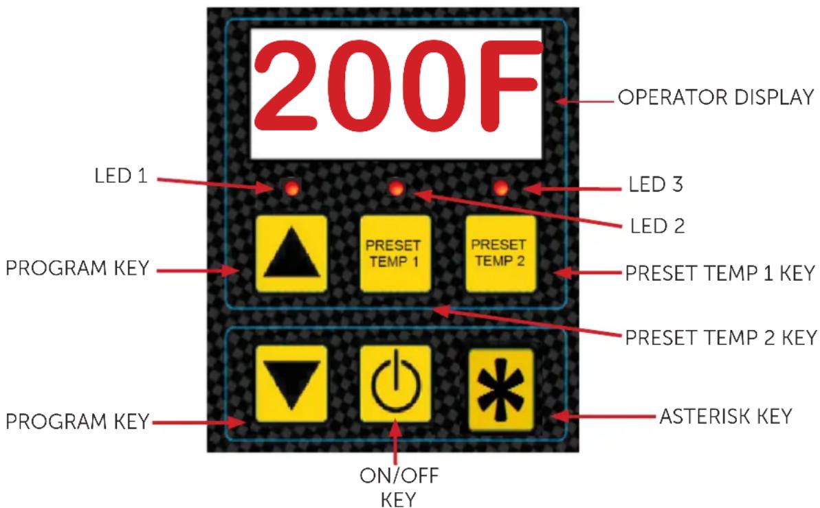
Fig 4.D
This appliance has a digital control temperature board that has two modes of operation.
- Operational Mode
- Manager Mode
Operational mode is the most used mode and the appliance operates as the keyboard overlay indicates during day to day product production.
Operational Mode Key Functions

ON/OFF Key - Dual Function Key; In the
"OFF" mode when pressed it turns on the griddle. When "ON" pressing and holding the key for five seconds turns the commercial appliance off.

Up Arrow Key - This key when pressed
will increase the set cooking temperature.
Unless in the Loc mode. Press and hold key for approximately three seconds to initialize the temperature adjust mode.

Down Arrow Key - This key when pressed decrease the set cooking temperature.
Unless in the Loc mode. Press and hold key for approximately three seconds to initialize the temperature adjust mode.


PRESET TEMP 1 and 2 Key - When
pressed and held for three seconds the system will select the preset set temperature that was set previously or the factory default temperature of 375^ F for Preset Temp 1 and 400^ F for Preset Temp 2. LED 2 will flash for Preset Temp 1 and LED 3 for Preset Temp 2.

or Asterisk or Temp Display Key-
Used as a multi-function key for operation and programming. Button varies based on model.
Press the ON/OFF switch and the griddle will start to pre-heat and LED 1 will blink. Any time the appliance is turned on it will operate and heat to the default set temperature or the last regulated Non-Preset temperature (Factory default is 350°F).
The display will show the current temperature until the set temperature is met, then LED 1 will go solid (FIG 4.D). The display will go to a "rdY" display or show the set temperature depending on the programming when the appliance was initially installed and setup.
(Factory default is "rdY")
PRESETS

Press the ON/OFF switch (Fig 4.D) and the griddle will start to pre-heat and LED 1 will blink.
Press and hold any PRESET KEY or for three seconds or until the LED 2 or LED 3 blinks.


The selected preset LED will blink and the display will show the current temperature and increase or decrease depending on the set temperature until it has reached the set preset temperature for that preset key and then go solid and the display will go to a "rdY" or show the set temperature depending on the programming when the appliance was initially installed and setup. The temperature will remain at the preset temperature until the griddle is turned off and back on.
The factory defaults for the preset keys are:
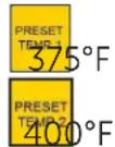
4.2.2 MANAGER MODE PROGRAMMING
Prior to using the commercial appliance a few operational items need to be determined.
- Default set temperature
- Preset 1 set temperature
- Preset 2 set temperature
- Operator lockout of set temperatures or "on the fly" temperature set
Default Set Temperature - is the temperature that the commercial appliance will heat up to when turned on.
Preset 1 Set Temperature - is an alternative set temperature that the commercial appliance will heat up to when activated from the keypad.
Preset 2 Set Temperature - is an alternative set temperature that the commercial appliance will heat up to when activated from the keypad.
Set Temperature Lockout - If turned on in the manager mode will lock in the set temperatures that were last saved in memory. If not set to active (Loc), the set temperatures can be set lower or higher than the last saved value.
To change the preset temps, attend the following steps:
- Power the unit on, the display will show the default temp (factory set to 350^ F).
- Hold the ▲P arrow until the display reading starts to increase.
- At this point, the ▲P or DOWN arrows can be used to increase or decrease the griddle temperature
- Once the new desired preset point has been reached. Push and hold the PRESET button you wish to set this temperature to.
- The unit will power off.
- When the unit is powered back on, push and hold the PRESET button for three seconds, the new temperature should be programmed.
Managers mode is used to setup initial operational parameters for the appliance prior to the first time of production use.
Manager's mode
- Entering Managers mode, press and hold the DOWN arrow key and the ASTERISK key together for about eight seconds, to initiate the programming mode. When the mode is accessed, all three LED lights will blink synchronously.
- Once in managers mode, the display will show the DEFAULT COOK TEMP, (see Fig 4.E, P#1)
- To cycle between programs, use UP arrow key and DOWN Arrow key. For example, to reach Program #2, Ready Mode Display, the UP arrow would be pushed once, cycling from Program #1 Default Cook Temperature to Program #2.
- To adjust the selected program, use PRESET 2 key or ASTERISK key to adjust the Program Settings (Fig 4.E & 4.F).
- When all changes are completed Exit the Managers mode and save the new parameters by pressing the PRESET 2 key
| Mode P# LED1 LED2 LED3 Program description Default Display Min Setting Max Setting | |||||||||
| 0 | B | B | B | Unit of Measure | (°F) | 0/00 | 0/00 = F | 0/01 = C | |
| 1 | B | B | B | Default Cook Temperature | 350F175C | 350F175C | 200F90C | 400F205C | |
| 2 B | B | B | Ready Mode Display (see table below for further detail) | 0 | 2/00 | 0 | 3 | ||
Fig 4.E This chart illustrates the programming logic and program level indication
| P#2 Value | Default Display | Display when there is a UP, PRESET TEMP 1 or momentary PRESET TEMP 2 key press | Display when there is an ASTERISK key press |
| 0/00 | rdY | Set Point Temperature | Set Point Temperature |
| 1/00 | Set Point Temperature | Set Point Temperature | Actual Temperature |
| 2/00 | rdY | rdY | rdY |
| 3/00 | Set Point | Set Point Temperature | Set Point Temperature |
Fig 4.F This chart illustrates details for Parameter 2 Mode Display
Programming Example - Adjusting the Default Temp.
- Press and hold the ▼ DOWN arrow key and the ✱ Asterisk key together for about eight seconds, to initiate the programming mode. When the mode is accessed, all three LED lights will blink synchronously.
- The display will show the default temperature (350°F from factory).
- Use the use PRESET 2 key or ✪ Asterisk key to increase or decrease the temperature on the display.
- With the desired temperature displayed the PRESET 2 key to save. The unit will power down.
- When the unit is restarted, the display will now show the new default temperature and start heating.
4.2.3 CONTROL REFERENCE GUIDE
| MODE LED Indicators DISPLAY NOTES | |||
| Off All LED's are off when powered down. | Off when powered down. When powered On, the controller would FLASH at a 1 Hz rate the current set temperature for 5 seconds. After this period the controller would go to Warm Up / Cool Down Mode. | To turn unit on: depress theOn/Offkey. To turn off the unit, disable outputs, save the current set point temperature (see details in "Other Features") and turn off the display: press and hold theOn/Offkey for approximately five seconds. | |
| Warm Up / Cool Down | Blinking LED above the selected temperature key (LED 1, 2 or 3). If default condition then LED 1. If Preset 2 is selected then LED 3 If Preset 1 then LED 2 | Actual temperature when no keys depressed, or set temperature of the Preset/Manual key when keyUP arrow key PRESET 1 key or PRESET 2 keyis momentarily pressed. | Upon power-on or whenever another temperature setting is made, the unit will enter this mode and will exit this mode only when the actual temperature has regulated. |
| Ready Mode LED above the selected key will be ON | Default display and alternate display options will be determined according to Program #2 value as shown in Fig 4.E & 4.F | Once has regulated, the indicator LED above the selected key will go to solid ON. For details on display operation, please refer to Program #2 value as shown in Fig 4.E & 4.F | |
| Set Temperature (On the fly) | All indicator LEDs blinking | Set Point Value when user Lock Mode is OFF, or "Loc" when User Lock Out Mode is ON | If the User Lock Out Mode is OFF, the set temperature can be adjusted. To set the temperature, press either theAParrowkey or theDOWN arrow keyand hold for approximately 3 seconds. The controller will load and display Default Cook Temp and enter set temperature mode. Press theParrow keyto increment or theDOWNarrow keyto decrement from the current temperature setting. Wait for five seconds. If there are no other key presses, the unit will auto start to the new setting. Press theOn/Offkey to exit without saving. |
| Select Preset Temperature | Selected Preset indicator LED blinking | Set Point Value To select an alternate preset temperature, if inPRESET TEMP 1setting, pressPRESETTEMP 2 keyand hold for approximately three seconds. If inPRESET TEMP 2 setting, pressPRESET TEMP 1key and hold for approximately three seconds. | |
| MODE LED Indicators | DISPLAY NOTES | ||
| Set Preset Temperature | All indicator LEDs blinking. Then the selected preset key will blink for 3 -5 seconds. | Set Point Value Use the same process to change the temperature as detailed in Set Temperature (On the fly), to adjust the Set Temperature. Once the correct temperature is displayed, and before the five second time out, press and hold the PRESET TEMP 1 key or the PRESET TEMP 2 key to save the displayed value to the desired preset key and to exit this mode. Press the On/Off key to exit without saving.Default Values:PRESET TEMP 1 = 375°FPRESET TEMP 2 = 400°F | |
| Display Temperature Mode | Current Temperature function LED on | Actual temperature | Pressing the Asterisk key and the Arrow Key will display the current actual temperature when the unit is in Ready Mode. |
| User Lockout Mode | All LEDs on solid | "Loc"or "ULoc" | To Set USER LOCKOUT mode, press and hold the On/Off key and the Asterisk key for approximately four seconds while the controller is ON. After four seconds, the USER LOCKOUT parameter will toggle and the display will show either "Loc" or "ULoc". When buttons are released, the controller will store the new USER LOCKOUT parameter value into NVM.Up Arrow key (Increment) and the Down Arrow key (Decrement) will be inoperable and the user can't store new values into the Preset 1 or 2 keys.When Up Arrow key or the Down Arrow key (Set temperature on the fly mode) are held for three seconds the display will show "Loc" when in the "Loc" mode |
4.3 COOKING
4.3.1 CLEAN AFTER INSTALLATION
It is recommended that you clean your ACCU-STEAM™ griddle thoroughly before using it for the first time. To clean the appliance cooking surface, just simply wash it down with a solution of mild soap and water, then rinse thoroughly with clean water and wipe dry with a clean towel.

Please use caution as temperatures on around the griddle cooking surface and cause severe burns.
4.3.2 SEASONING
Once the cooking surface has been cleaned, turn the appliance on via the digital control key pad and set the temperature to 200°F. (93°C), and allow the griddle cooking surface to heat for 10 minutes. Using a high temperature oil, such as Pan and Grill Shortening™, Whirl™ or equivalent, pour enough to cover the entire appliance cooking surface. Do not use standard vegetable oil to season the griddle cooking surface. It may cause food to stick and result in improperly cooked food. Work this seasoning oil into the griddle surface with a regular heavy-duty scrub pad for about 5 minutes, making sure that you scrub the seasoning oil over the entire appliance cooking surface. After the entire cooking surface has been scrubbed with seasoning oil for 5 minutes, simply wipe or squeegee off excess oil from cooking surface. Your appliance is now ready to use!
If you use chemicals to clean your griddle periodically or on a schedule, you may need to repeat this process after the use of these chemicals.
Preheating
Press the ON/OFF and set the desired temperature. The griddle will increase its surface temperature at an average rate of 15^ F ( 8^ C) per minute. It takes approximately 25 minutes to raise the griddle from room temperature to its maximum temperature of
400°F (204°C). The appliance will be preheated when the selected set temperature is displayed and the corresponding LED goes solid. Please use caution as temperatures on and around the griddle cooking surface could cause severe burns.
4.3.3 COOKING
Begin cooking only after the appliance has been preheated to the desired temperature. Please note these facts:
- You can cook all the way to the edges of the cooking surface because the temperature does not vary across the entire cooking surface.
- You can turn the product to the same spot because the cooking surface has near instant heat recovery.
- It will always cook the same, regardless of product load or surface coverage.
Accurate Cooking Temperatures Because of the inaccurate surface temperatures and long recovery times common with other griddles cooking surfaces. It is doubtful you were cooking at the set temperature or the temperature you wanted. Adjust the temperature on the Accu-Steam™ griddle and it will not change or vary by the location on the griddle surface. There are no hot or cold zones.
4.3.4 SURFACE TEMPERATURES
The digital temperature control and temperature sensor are more accurate than any other device to measure the cooking surface temperature in this appliance. Any other digital device may show a difference. The important use of the external temperature measuring device is to ascertain that the temperatures are within ±5^ F across the entire cooking surface of the appliance.
Due to the construction material of the cooking surface an infrared temperature probe can't be used.
The proper measurement tools to use is a calibrated weighted temperature probe and digital temperature meter set (Fig 4.G).
A number of factors can cause surface temperature reading differences such as:
- Air movement across the appliance cooking surface can lower the temperature reading as much as 10°F from the set temperature.
- Proper calibration of the temperature measuring device.
- How long after the heat light turned off before temperature measurement was completed.
Assure the cooking surface is clean before measuring the surface temp. See section 4.4 for information on cleaning.
Do not use an infrared or a mechanical temperature gauge to measure the surface temperature of the appliance as it will not be accurate and will provide a false temperature reading of the cooking surface temperature. See Fig 4.G for proper surface temperature measuring tools.
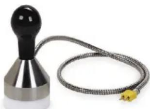
natural_image
Close-up of a metallic chaper with a coiled cable and a small yellow sensor (no text or symbols visible)Weighted Temperature Probe

natural_image
Blue ATIKINS digital measuring device with tassel, no visible text or symbols on device bodyDigital Temperature Reading Device
Fig 4.G
4.3.5 CHECKING SURFACE TEMPERATURES
- Verify griddle is level front to back and side to side before attempting this procedure.
- With the griddle plugged in, set the temperature to 300^ F.
- Place the weighted temperature probe in the center in the first 1/3rd of the griddle cooking surface on a small amount of high temperature cooking oil. Make sure that the probe is between the griddle weld stud dimples to assure a proper reading.
- Allow the griddle to heat to the initial temperature setting.
- Place weighted temperature probe and record 9 temperatures according to the chart below (Fig 4.H).
- Temperatures shall be within ±5^ F of each other across the entire surface.

Fig 4.H - Top down view of griddle cooking surface
4.3.6 GREASE TRAY
The grease tray is located on the front right side of the appliance and has a gripping handle on the front and the inside middle to assist in safely managing the hot contents. Models used for maritime have a locking style and this lock must be released before sliding the tray out. Use caution when emptying the grease tray as contents in this tray could cause severe burns. The grease tray should be checked periodically and emptied as necessary to prevent an overflow or dangerous condition. To assist in indicating an overfill condition a hole located on the front of the tray will allow grease to escape when overfilled.


⚠️ Allow the grease tray contents to cool below 140^ F before removing. Be careful not to spill the contents of the grease tray as it can cause a slipping condition which could cause a personal injury
The grease tray contents could cause severe burns. Slowly remove the grease tray from the appliance to avoid spilling the contents.
4.4 CLEANING
Always disconnect from power source before cleaning or servicing.
If the cooking surface of the appliance has standing grease and the griddle is at a high temperature using water or ice can cause the grease to splatter and cause skin burns.
The grease tray contents could cause severe burns. Slowly remove the grease tray from the griddle to avoid spilling the contents.
Do not use a water-jet to clean this appliance as it can harm the electronic components.
Do not use a stone or brick to clean griddle cooking surface. Only use a fabric scrub pad.
4.4.1 DAILY CLEANING
Cleaning the cooking surface during the work shift can be performed with a sharp scraper. When heavy cleaning at the end of a shift or periodically through the day is needed, the following is recommended:
- Empty the grease tray as often as needed and always prior to end of shift cleaning.
- Turn the griddle off and allow it to cool to between 220°F and 240°F (104°C and 116°C). Scrape off heavy deposits and remove any standing grease before proceeding with the cleaning process.
- Use water, ice and/or griddle cleaner as needed. For example, the 3M Scotch-Brite™ Quick Clean Griddle System provides the Scotch-Brite polishing pads, quick clean liquid, pad holder and squeegee. Clean-up is very easy using these tools with the quick clean liquid, water, ice or combinations of these liquids. Seasoning the cooking surface after the daily cleaning is recommended.
• After the non-cooking surfaces are cool to the touch. Empty the grease tray and wash with a mixture of dish detergent and clean water and dry with a clean dry cloth.
- Clean the non-cooking surfaces with a damp cloth and dry with a clean dry cloth. Use a high quality stainless steel cleaner on a clean cloth to reduce grease buildup. Follow the manufacturers instructions located on the cleaner.
- It is recommended that a high quality stainless steel polish be used on the non-cooking surfaces as the last step in keeping surfaces in new like condition and lengthen the usable life of this commercial appliance. Follow the manufacturers instructions located on the polish.
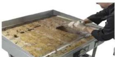
Step 1 Scrape off Heavy Deposits
natural_image
Person handling a tray with food on a metal tray (no visible text or symbols)Step 2 Cool griddle to 220^ F and apply water or ice. Use a long handled nonmetallic scrub to scrub the cooking surface.

natural_image
Person in chef uniform stirring food on a large griddle (no visible text or symbols)Step 3 Add additional water or ice and using a long handle squeegee and pull to the grease tray.

natural_image
Person cooking on a large griddle with visible steam and food (no text or symbols)Fig 4.H
5. PLANNED MAINTENANCE CHECKLIST

It is recommended that you contact your AccuTemp authorized service provider to setup a planned tenance program to keep your appliance operating in the most efficient manner. AccuTemp mmends a minimum of a yearly schedule.
| PM TASK DESCRIPTION | Daily Bian | Annual Yearly | |
| Verify that the appliance is level and properly located under the hood. | X | X | |
| Verify that the temperature controller is working properly and that there are no rips in the label. | XXX | ||
| Check that the splash shield at the top of the control panel is under the rail provided. If not water and or grease can migrate into control panel. | X | X | |
| Inspect the control compartment for foreign particulate and any loose wiring or connections. | X | X | |
| Check that the power supply cord is not frayed, outer covering is not degraded or any bare cooper is visible. Replace if required. | XXX | ||
| Verify amp draw to listed amp requirements on the data tag of the appliance. | X | X | |
| If on an AccuTemp Stand verify mounting fasteners are in place and tight. If not correct. If the stand has casters check that the wheels are intact and that they are mounted correctly. If grease covered clean with a mild detergent and clean water. Dry completely. Apply a food grade silicone to the locking mechanism. | XXX | ||
| Complete a 9 point temperature test to check for even temperature across the surface of the cooking surface. | X | X | |
| Check for grease buildup in the grease drawer container and clean it with a damp towel saturated with a mild detergent and clean water. Dry with a clean dry towel. | XXX | ||
| After all metallic areas are cool to the touch, clean external metal surfaces except the cooking surface. With a damp clean towel saturated with a mild detergent and clean water. Dry with a clean dry towel. | XXX | ||
| Season the cooking surface as outlined in this manual. | X |
6. SERVICE & TROUBLESHOOTING
Always disconnect from power source before cleaning or servicing.
⚠️ Any in-field modification that bypass the built in safety features of this appliance will result in death or serious injury.
⚠ Use of any replacement parts other than those supplied by AccuTemp can cause injury to the operator or damage the appliance and voids all warranties.
There are no user-serviceable parts. To prevent electrical shock do not open the access panel covers.
Service should be completed by AccuTemp authorized service groups. Service completed by unauthorized groups will void all factory warranties.
AccuTemp Technical Service must be contacted for all warranty service requests. If not the warranty claim maybe denied.
6.1 APPLIANCE WILL NOT TURN ON
- Make sure the appliance is plugged in.
- Check the facility circuit breaker (or fuse) supplying the unit
6.2 HEAT LIGHT WILL NOT COME ON
- Make sure the appliance is not hotter than the temperature you have it set for. If you have turned down the temperature of the griddle, the heat light will not come on again until the cooking surface drops below the temperature you have set.
- See if the heat light is coming on intermittently. While operating in a normal condition, the heat light cycles on and off periodically when at temperature.
6.3 UNEVEN OR INACCURATE SURFACE TEMPERATURES
- Verify the appliance is level front to back and side to side.
- Verify the surface temperature with an accurate digital surface probe thermometer.
- Use of an infrared or mechanical thermometer will not give an accurate reading of the appliance cooking surface temperatures.
- Contact AccuTemp Technical Service for additional instructions.
6.4 UNIT WILL NOT TURN OFF
- This symptom, which is extremely rare, indicates a serious control malfunction.
- Turn off the appliance electrical supply at the source and contact AccuTemp Technical Service for additional instructions.
- Make sure to hold the On/Off Key for a minimum of 3 seconds until the display turns off.
6.5 PRESET TEMPERATURES ARE NOT WORKING
- Check the preset temperature by pressing each key momentarily to display the Preset Temp. If the Preset Temp settings are correct and the appliance will not regulate to the Preset Temp contact AccuTemp.
6.6 ERROR CODE DISPLAYED
E001 Displayed
Open Temperature Sensor or defective temperature input on Temperature Control Board.
E002
Shorted Temperature Sensor or defective input on the Temperature Control Board.
6.8 OVER-TEMP LIGHT ILLUMINATED
When this error is lit an over-temp condition was sensed and will turn off the appliance
To correct, turn the appliance off and wait one minute and turn the appliance back on.
If problem persists - call AccuTemp Service

Fig 6.A
Over-Temp Light
(Heat light will also be illuminated in normal operation)
AccuTemp Products, Inc. Technical Service Technician is available: Monday thru Sunday, 7:00am to 7:00pm EST.
| Toll Free 800 480-0415 | |
| Office 260 469-3040 | |
| Fax 260 469-3045 | |
| Email -Service service@AccuTemp.net | |
| Email-Parts parts@AccuTemp.net | |
| Web Site www.AccuTemp.net |
WARRANTY SERVICE PROCEDURE
- Contact the AccuTemp Technical Service group for all warranty service requests.
- Be prepared to supply the serial number, address, location phone and contact for the location.
- Be prepared to complete a few simple tasks to help evaluate the problem.
- If the problem requires service at the location the AccuTemp Technical Service group will dispatch the nearest authorized service agent.

Service should be completed by
AccuTemp authorized service groups. Service completed by unauthorized groups will void all factory warranties.

AccuTemp Technical Service must beacted for all warranty service requests. Not the warranty claim maybe denied.
- INSTALLATION/OPERATORS MANUAL ACCU-STEAM ELECTRIC G2 GRIDDLE
- WARNING SYMBOL DEFINITIONS
- SYMBOL DEFINITIONS
- Symbol Icons
- DANGER
- CAUTION
- NOTE
- CAUTION - HOT SURFACE
- DANGEROUS VOLTAGE
- EARTH GROUND
- IMPORTANT FOR YOUR SAFETY
- WARNING
- WARNING & CAUTION NOTES
- General Information
- Unit Specifications
- EQUIPMENT DATA PLATE
- INSTALLATION
- TABLE TOP/STAND MODEL
- INSTALLATION NOTICE
- UNPACKING
- GRIDDLE LIFTING
- LOCATION AND PLACEMENT
- LEVELING
- TABLE TOP
- AccuTemp STAND
- STAND INSTALLATION
- ELECTRICAL CONNECTIONS
- ELECTRICAL SUPPLY
- ELECTRICAL REQUIREMENTS
- GROUNDING INSTRUCTIONS
- OPERATION
- HOT
- VISUAL IDENTIFICATION
- CONTROL OVERVIEW
- PRESETS
- MANAGER MODE PROGRAMMING
- Manager's mode
- CONTROL REFERENCE GUIDE
- COOKING
- CLEAN AFTER INSTALLATION
- SEASONING
- Preheating
- COOKING
- SURFACE TEMPERATURES
- CHECKING SURFACE TEMPERATURES
- GREASE TRAY
- CLEANING
- DAILY CLEANING
- PLANNED MAINTENANCE CHECKLIST
- SERVICE & TROUBLESHOOTING
- APPLIANCE WILL NOT TURN ON
- HEAT LIGHT WILL NOT COME ON
- UNEVEN OR INACCURATE SURFACE TEMPERATURES
- UNIT WILL NOT TURN OFF
- PRESET TEMPERATURES ARE NOT WORKING
- ERROR CODE DISPLAYED
- OVER-TEMP LIGHT ILLUMINATED
- WARRANTY SERVICE PROCEDURE
Brand : AccuTemp
Model : AccuSteam EGF2083B4850-T1
Category : Grill plate