ZG227LA-60 - Lawn mower KUBOTA - Free user manual and instructions
Find the device manual for free ZG227LA-60 KUBOTA in PDF.


| Product Type | Zero-Turn Lawn Mower |
| Brand | Kubota |
| Model | ZG227LA-60 |
| Engine Type | Kubota D722 Diesel Engine |
| Engine Power | 22 hp (16.4 kW) |
| Cutting Width | 60 inches (152 cm) |
| Cutting Height Range | 1.5 - 4.5 inches (38 - 114 mm) |
| Transmission | Hydrostatic with dual pumps |
| Fuel Capacity | 7.9 gallons (30 liters) |
| Weight | 1,100 lbs (499 kg) |
| Overall Dimensions (L x W x H) | 80 x 66 x 45 inches (203 x 168 x 114 cm) |
| Turning Radius | Zero (true zero-turn) |
| Forward Speed | 0 - 8 mph (0 - 12.9 km/h) |
| Reverse Speed | 0 - 5 mph (0 - 8 km/h) |
| Blade Engagement | Electric clutch |
| Seat | High-back suspension seat |
| Steering | Lap bar controls |
| Safety Features | Operator presence system, seat switch, parking brake |
| Maintenance Interval | Oil change every 100 hours; air filter every 200 hours |
| Warranty | 3-year limited warranty |
Frequently Asked Questions - ZG227LA-60 KUBOTA
User questions about ZG227LA-60 KUBOTA
0 question about this device. Answer the ones you know or ask your own.
Ask a new question about this device
Download the instructions for your Lawn mower in PDF format for free! Find your manual ZG227LA-60 - KUBOTA and take your electronic device back in hand. On this page are published all the documents necessary for the use of your device. ZG227LA-60 by KUBOTA.
USER MANUAL ZG227LA-60 KUBOTA
5900-14th Avenue, Markham, Ontario, L3S 4K4, Canada
Госкв. : KUBOTA EUROPE S.A.S
19-25. Rus-Jules Varemysso, 7.1. BP88, 95101 Argentina Cedex, France
Telephone : (33)1-3426-3434
UBOTA EUROPE S.A.S Italy Branch
Vic Grandi, 20 20068 Paschiera Boromo (MI) Italy
161841301 (39502-51650377)
Germany : KUBOTA (DEUTSCHLAND) GmbH
Serele der St. 3-5 83110 Podgau /Nieder-Hoden, Germany
Telephones : (49)5
Dowor Road, Torino, Orefastiny, GXO 2UN, UK
Telephone : (401)844-214530
Spain KUBOTA ESPAÑA S.A.
Avenida Bocomba No.5, Poligno Industrial la Locuna, Lecenes, 28914 (Madrid) Spain
Telephone : (34)01-508-6442
UBOTA AUSTRALIA PTY LTD.
25-29 Permas Way, Truganina
Telephone : (51)3-6394
ME KUBOTA SON. BHD,
No.3 Jesari Seputu 25/12/3 Lumen Pernudalman Axis, Sekuran 26, 40490 Shah Alam, Salapan Road Chuan Malaysia
Sekyeh 25, 4090 Shah Alam, Selangx Darul Ensal Malaysia Telephone : (80)3-736-1388
Philippines: KUBOTA PHILIPPINES, INC.
232 Quiring Highway, Buena, Queen City 1106, Philippines
Telephone : (53)2-422-3500
Taiwan : SHIN TAIWAN AGRICULTURAL MACHINERY CO., LTD.
- Fengping 2nd Rd, Taiyao Shiang Kaohsiung 83107, Taiwan R.O.O.
Telephone : (896)7-702-2333
T KUBOTA MACHINERY INDONESIA
Tower A at LightLight@Kassblanka Lantai 16
Jalan Haya Casablanka Kav. 88, Jakarta 12870 Indonesia
Telephone : (52)-21-20566-726
AM KUBOTA CORPORATION CO., LTD.
101719-24 M55 20, Navanskim Industrial Estate, Tambon Khonghuang, Anphur Khonghuang, Balhunthesi 18170, Thailand
Telephone: (8512-909-0306)
Kuwa: KUROTA KOREA CO., LTD.
41.27. Iwjuuwen ell, Barksan mycen, Gimie si, Inajibuk du, Korea
Telephone : (82)-63-544-5822
UBOTA AGRICULTURAL MACHINERY INDIA BVT. LTD
No.15, Maclavakkam Road, Shoumangalir, Chengal-600119, J.N., India
Telephone : (91)44-6104-1500
Vietnam : KUBOTA VIETNAM CO., LTD.
Lot B-342-CN, My Phuoc 3 Industrial Park, Thei Hua Word, Ben Cat Town, Binh Duong Province, Vietnam
Telephone : (84)-274-3577-507
KUBOTA Corporation
English, Spanish (U.S.A.)
Code No.
Código n° K3272-7122-2
OPERATOR'S MANUAL
KUBOTA
ZERO TURN MOWER
MANUAL DEL OPERADOR
KUBOTA
natural_image
Line drawing of a golf mobility vehicle with visible wheels and handle (no text or symbols)MODELS ZG222A
MODELOS ZG227A
18DA2DNAP0010
PRINTED IN USA
IMPRESO EN E.E.U.U.
© KUBOTA Corporation 2010
READ AND SAVE THIS MANUAL
LEA Y CONSERVE ESTE MANUAL
Kubota
KUBOTA Corporation is …
Since its Inception in 1890, KUBOTA Corporation has grown to rank as one of the major firms in Japan.
To achieve this status, the company has through the years diversified the range of its products and services to a remarkable extent, until today, 30 plants and 35,000 employees produce over 1,000 different items, large and small.
All these products and all the services which accompany them, however, are unified by one central commitment. KUBOTA makes products which, taken on a national scale, are basic necessities. Products which are indispensable, products intended to help individuals and nations fulfill the potential inherent in their environment. For KUBOTA is the Basic Necessities Giant.
This potential includes water supply, food from the soil and from the sea, industrial development, architecture, construction and transportation.
Thousands of people depend on KUBOTA's know-how, technology, experience and customer service. You too can depend on KUBOTA.
KUBOTA Corporation es ...
natural_image
Line drawing of a small golf mobility vehicle with visible wheels and handlebars (no text or symbols)ABBREVIATION LIST
| Abbreviations | Definitions |
| API | American Petroleum Institute |
| ASTM | American Society for Testing and Materials, USA |
| fpm | Feet Per Minute |
| HST | Hydrostatic Transmission |
| m/s | Meters Per Second |
| PTO | Power Take Off |
| RH/LH | Right-hand and left-hand sides are determined by facing in the direction of forward travel |
| ROPS | Roll-Over Protective Structures |
| rpm | Revolutions Per Minute |
| r/s | Revolutions Per Second |
| SAE | Society of Automotive Engineers |
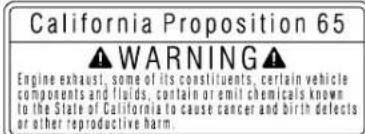
California Proposition 65
WARNING
Engine exhaust, some of its constituents, certain vehicle components and fluids, contain or emit chemicals known to the State of California to cause cancer and birth defects or other reproductive harm.
IMPORTANT
The engine in this machine is not equipped by the manufacturer with a standard spark arrester.
It is a violation of California Public Resource Code Section 4442 to use or operate this engine on or near any forest-covered, brush-covered land, or grass-covered land unless the exhaust system is equipped with a working spark arrester meeting state laws. Other states or federal areas may have similar laws.
Canadian Electromagnetic Compatibility (EMC): This machine complies with Industry Canada ICES-002.
UNIVERSAL SYMBOLS
As a guide to the operation of your machine, various universal symbols have been utilized on the instruments and controls. The symbols are shown below with an indication of their meaning.

Safety Alert Symbol

Gasoline Fuel

Fuel-Level

Parking Brake

Engine-Stop

Engine-Run

Starter Control

Power Take-Off Clutch Control-Off Position (Disengaged)

Power Take-Off Clutch Control-On Position (Engaged)

Hours

Cutting Height

Mower-Lowered position

Mower-Raised position

Fast

Slow

Engine Speed Control

Battery

Oil Pressure

Choke
FOREWORD
You are now the proud owner of a KUBOTA ZERO TURN MOWER. This machine is a product of KUBOTA's quality engineering and manufacturing. It is made of excellent materials and under a rigid quality control system. It will give you long, satisfactory service. To obtain the best use of your machine, please read this manual carefully. It will help you become familiar with the operation of the machine and contains many helpful hints about machine maintenance. It is KUBOTA's policy to utilize, as quickly as possible, every advance in our research. The immediate use of new techniques in the manufacturing of products may cause some small parts of this manual to become outdated. KUBOTA distributors and dealers will have the most up-to-date information. Please do not hesitate to consult them.

SAFETY FIRST
This symbol, the industry's "Safety Alert Symbol", is used throughout this manual and on labels on the machine itself to warn of the possibility of personal injury. Read these instructions carefully. It is essential that you read the instructions and safety regulations before you attempt to assemble or use this unit.

DANGER: Indicates an imminently hazardous situation which, if not avoided, will result in death or serious injury.

WARNING: Indicates a potentially hazardous situation which, if not avoided, could result in death or serious injury.

CAUTION : Indicates a potentially hazardous situation which, if not avoided, could result in minor or moderate injury.
IMPORTANT : Indicates that equipment or property damage could result if instructions are not followed.
NOTE : Gives helpful information.
CONTENTS
MOUNTING THE MOWER DECK 9
DISMOUNTING THE MOWER DECK 10
OPERATING THE ENGINE....11
MOUNT AND DISMOUNT MACHINE SAFELY 11
STARTING THE ENGINE....11
Throttle Lever and Choke Knob....13
Key Switch....13
CHECK DURING OPERATING 14
Immediately Stop the Engine if:.... 14
Easy Checker (TM)....14
Fuel Gauge....14
Fuel Pump 14
Hour Meter....15
COLD WEATHER STARTING 15
WARMING UP 15
Warm-up and Transmission Oil in the Low Temperature Range....15
JUMP STARTING 16
STOPPING THE ENGINE....17
Engine Stop (By manual)....17
OPERATING THE MACHINE....18
Changing Lubricating Oil for New Machines....18
Engine Break-in....18
Machine Break-in....18
OPERATING FOLDABLE ROPS 19
To Fold the ROPS 19
To Raise the ROPS to Upright Position.... 20
Adjustment of Foldable ROPS....20
STARTING 21
Operator's Seat....21
Seat Belt 21
Hydraulic Lift Control Pedal 21
Throttle Lever....22
Parking Brake Pedal 22
Motion Control Lever 23
WORK LIGHT (OPTIONAL KIT) 26
STOPPING....26
PARKING 26
TRANSPORTING....27
MAKING THE MOST OF YOUR MOWER....28
ADJUSTING CUTTING HEIGHT 28
OPERATING MOWER 31
PTO Lever 31
Starting 31
TIRES AND WHEELS 32
TIRES....32
Inflation Pressure....32
WHEELS 32
Remove and Install Front Caster Wheels....33
MAINTENANCE....34
SERVICE INTERVALS 34
PERIODIC SERVICE CHART LABEL 36
LUBRICANTS AND FUEL 37
PERIODIC SERVICE....39
HOW TO OPEN THE HOOD AND STEP 39
Hood 39
Step 39
HOW TO RAISE THE OPERATOR'S SEAT 40
HOW TO OPEN THE LEVER GUIDE....41
LIFT-UP POINT 41
Front side: 41
Rear side: 42
DAILY CHECK 42
Checking Engine Oil Level....43
Checking Amount of Fuel and Refueling 43
Checking and Cleaning Air Intake Screen and Air Intake Area to Prevent
Overheating 44
Checking Tire Pressure 45
Inflation Pressure....45
Checking Transmission Fluid Level 46
Lubricating All Grease Fittings....46
Checking Movable Parts....47
EVERY 50 HOURS....47
Checking Engine Start System....47
Checking OPC System....48
Checking Gear Box Oil Level....49
Greasing 50
Oiling....52
EVERY 100 HOURS....52
Changing Engine Oil....52
Cleaning Air Cleaner Primary Element 53
Cleaning Engine Shroud Panel.... 53
Cleaning Engine Oil Cooler Fins.... 55
Checking Fuel Filter....56
Cleaning Fuel Filter Bowl....57
Adjusting Parking Brake 58
Battery Condition 60
Adjusting Throttle Cable 61
Checking Carbon Canister Air Filter 62
EVERY 150 HOURS....62
Changing Gear Box Oil....62
EVERY 200 HOURS....64
Replacing Engine Oil Filter 64
Checking Spark Plug Condition & Gap.... 64
Replacing Transmission Oil Filter Cartridge 65
Adjusting the Motion Control Lever Pivot....66
Cleaning Engine Shroud....66
EVERY 400 HOURS....66
Changing Transmission Fluid and Rear Axle Gear Case Oil (RH and LH) 66
Cleaning Transmission Strainer....68
Replacing Fuel Filter....68
EVERY 500 HOURS....68
Adjusting Engine Valve Clearance 68
EVERY AFTER 1000 HOURS 68
Cleaning Combustion Chamber....68
EVERY 1000 HOURS or EVERY 1 YEAR....68
Replacing Air Cleaner Primary Element and Secondary Element....68
EVERY 1 YEAR....69
Checking Fuel Lines 69
Checking Hydraulic Hose 69
Checking Intake Air Line....69
Checking Engine Breather Hose 70
Checking Mower Gear Box Oil Seal 70
EVERY 2 YEARS....70
Replacing Carbon Canister Air Filter 70
EVERY 4 YEARS....70
Replacing Hydraulic Hose 70
Replacing Fuel Lines 70
Replacing Engine Breather Hose 70
Replacing Mower Gear Box Oil-Seal....70
Replacing Intake Air Line....70
SERVICE AS REQUIRED....70
Replacing Fuses....70
Checking and Replacing Blade.... 71
Replacing Mower Belt....73
Bleeding Fuel System....73
ADJUSTMENT....74
LEVEL MOWER DECK (Side-to-Side) 77
LEVEL MOWER DECK (Front-to-Rear) 78
GENERAL TORQUE SPECIFICATION 80
TIGHTENING TORQUE CHART 81
STORAGE 82
MACHINE STORAGE 82
REMOVING THE MACHINE FROM STORAGE....82
Fuel 82
Inspecting and Cleaning Fuel Filter Bowl 83
TROUBLESHOOTING 85
ENGINE TROUBLESHOOTING 85
BATTERY TROUBLESHOOTING 87
MACHINE TROUBLESHOOTING 87
MOWER TROUBLESHOOTING 88
ENGINE EMISSION RELATED INFORMATION....90
INDEX......91

SAFE OPERATION
Careful operation is your best insurance against an accident. Read and understand this manual carefully before operating the machine. All operators, no matter how much experience they may have had, should read this and other related manuals before operating the machine or any implement attached to it. It is the owner's obligation to instruct all operators in safe operation.
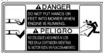
This mowing machine is capable of amputating hands and feet and throwing objects. Failure to observe the following safety instructions could result in serious injury or death.
1. BEFORE OPERATING
- The ZERO TURN MOWING MACHINE has different steering characteristics than other machines with a steering wheel and does not have a service brake pedal (but, has a parking brake lock pedal that can be used to stop the machine in an emergency. Normal slowing down and stopping is done with the motion control levers.). Read and understand the operators manual before operating the machine. Practice operating machine at low engine speed without mower engaged in an unobstructed area.
- Know your equipment and its limitations. Read all instructions in this manual and machine safety labels before attempting to start and operate the machine.
- Pay special attention to the safety labels on the machine itself.
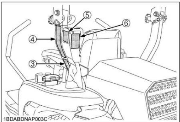
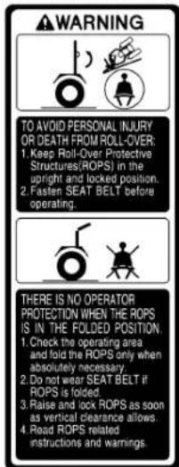
- KUBOTA recommends the use of a Roll Over Protective Structures (ROPS) and seat belt in almost all applications. This combination will reduce the risk of serious injury or death, should the machine be upset.
The machine is equipped with a Foldable ROPS, which may be temporarily folded down only when absolutely necessary for areas with height constraints. (There is no operator protection provided by the ROPS in the folded position. For operator safety the ROPS should be placed in the upright and locked position and the seat belt fastened for all other operations.)
If the ROPS is loosened or removed for any reason, make sure that all parts are reinstalled correctly before operating the machine.
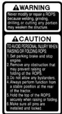
Never modify or repair a ROPS because welding, bending, drilling, grinding, or cutting may weaken the structure.
A damaged ROPS structure must be replaced, not repaired or revised.
If any structural member of the ROPS is damaged, replace the entire structure at your local KUBOTA Dealer.

(1) ROPS
(2) Seat belt
- Always use the seat belt when the ROPS is upright. Do not use the seat belt if the ROPS is down or if there is no ROPS. Check the seat belt regularly and replace if frayed or damaged.
- Do not allow any bystanders around or near machine during operation.
- Do not allow passengers, children or non-qualified operators on the machine at any time. The operator must remain in the machine seat throughout operation.
- Do not operate the machine or any attachments while under the influence of alcohol, medication, controlled substances or when fatigued.
- Do not wear loose, torn, or bulky clothing around machine. The clothing may catch on moving parts or controls, leading to the risk of accident. Wear and use any additional safety items such as hard hat, safety boots or shoes, eye and hearing protection, gloves, etc. as appropriate or required.
- Do not wear radio or music headphones while operating the machine. Safe operation requires your full attention.
- Carefully check the vicinity before operating machine or any implement attached to it. Clear the work area of objects (wires, rocks, etc.) that might be picked up and thrown. Check for overhead clearance which may interfere with a grass catcher.
- Check brakes and other mechanical parts for correct adjustment and wear. Replace worn or damaged parts promptly. Check the tightness of all nuts and bolts regularly. (For further details, see "PERIODIC SERVICE" and "ADJUSTMENT" section.)
- Keep all shields and guards in place. Replace any that are damaged or missing.

SAFE OPERATION-2
- Before allowing other people to use your machine, explain how to operate and have them read this manual before operation.
- In addition to the design and configuration of equipment, hazard control and accident prevention are dependent upon the awareness, concern and prudence of personnel involved in the operation, transport and maintenance of the equipment.
- Keep the machine and attachments in good operating condition and keep safety devices in place and in proper working condition.
- Do not modify the machine. Unauthorized modification may affect the function of the machine, which may result in personal injury.
- Use only implements approved by KUBOTA. Use proper ballast to front or rear of machine to reduce the risk of upsets. Follow the "Safe Operation" procedures, specified in the manuals with equipment.
- Keep your machine clean. Accumulations of dirt, grease, and trash can contribute to fires and lead to personal injury.
- The exhaust gas from the muffler is very hot. To prevent fire, do not expose dry grass, mowed grass, oil and any other combustible materials to exhaust gas. Use a spark arrester where required. Also keep the engine and muffler clean all the time.
2. OPERATING
Starting
- Always sit in the operator's seat when starting engine or operating levers or controls.
- Before starting the engine make sure that the motion control levers are in neutral lock, the parking brake is applied, and Power Take Off (PTO) is disengaged (OFF).
- Do not start engine by shorting across starter terminals. The machine may start in gear and move if normal starting circuitry is bypassed.
- Do not operate or idle engine in a non-ventilated area. Carbon monoxide gas is colorless, odorless, and deadly.
- Do not start engine while tilting deck.
- Check before each use that operator presence controls are functioning correctly. Test safety systems. (See "Checking Engine Start System" and "Checking OPC System" in "EVERY 50 HOURS" in "PERIODIC SERVICE" section.)
Do not operate unless they are functioning correctly.
◆Working
- Do not turn sharply when driving at high speed.
-
To avoid tip over, slow down when turning on uneven terrain or before stopping.
-
Do not operate near ditches, holes, embankments, or other terrain, which may collapse under the machine weight. The risk of machine tip over increases when the ground is loose or wet.
- Park the machine on a firm and level surface.
- Watch where you are going at all times. Watch for and avoid obstacles. Be alert at curbs, shrubs, near trees, and other obstructions and hidden hazards. Obstacles can damage machine (fuel hoses, wire harness etc.).
- Know what is behind you before backing up. Look to the rear before and when backing. Do not mow while in reverse unless absolutely necessary and make sure the area immediately behind you is clear of obstructions or holes and small children. Use extra caution when machine is equipped with Grass Catcher. Your view to the rear is restricted.
- When working in groups, always let others know what you are doing ahead of time.
- Do not drive machine on streets or highways. Watch for traffic when you cross roads or operate near roads.
- Be aware of the mower discharge direction and do not point it at anyone.
- When using any attachments, never direct discharge material toward bystanders. Do not allow anyone near the attachments while in operation.
Do not mow when bystanders are present in the mowing area. - To reduce fire hazards, keep the engine exhaust area free of grass or leaves.
- Be sure rotating blades and engine are stopped and the key is removed before placing hands or feet near blades and cleaning blockages or unclogging chute.
13.Shut the engine off and wait for all movement to stop before removing grass catcher or unclogging chute. - Watch the temperature gauge and maintain all screens to avoid overheating conditions.
- Always inspect the mower for damage after striking a foreign object. Repair or replace any damaged parts before restarting.
- Operate during daylight or in bright artificial light.
◆Children
Tragic accidents can occur if the operator is not alert to the presence of children. Children are attracted to the machine and mowing activity.
Never assume that children will remain where you last saw them.
- Keep children out of the mowing area and under the watchful care of another responsible adult.
- Be alert and turn machine off if children enter the area.
- Before and when backing, look behind and down for small children.
- Never carry children. There is no safe place for them to ride. They may fall off and be seriously injured or interfere with safe machine operation.
-
Never allow children to operate the machine, even under adult supervision.
-
Use extra care when approaching blind corners, shrubs, trees, or other obstructions that might hide children from sight.
- Do not mow in reverse unless it is absolutely necessary and make sure area to the rear is clear of children before doing so.
◆Operators, age 60 years and above
Data indicates that operators, age 60 years and above, are involved in a large percentage of machine-related injuries. These operators should evaluate their ability to operate the machine safely enough to protect themselves and others from serious injury.
◆Operation on slopes
Slopes are major factor related to loss-of-control and tip-over accidents, which can result in severe injury or death. All slopes require extra caution.
If you cannot back up the slope or if you feel uneasy on it, do not mow it.
If the engine stops when operating on a slope apply the parking brake immediately to prevent machine run away.
DO
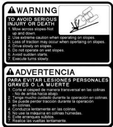
- To avoid tip over, operate across the slopes not up and down. Stay off hills and slopes too steep for safe operation.
- Remove obstacles such as rocks, tree limbs, etc.
- Stay alert for holes in the terrain and other hidden hazards. Keep away from drop-offs. Uneven terrain could overturn the machine. Tall grass can hide obstacles.
- Follow the manufacturer's recommendations for wheel weight or counterweights to improve stability.
- Keep all movement on the slopes slow and gradual. Do not make sudden changes in speed or direction.
- Avoid starting or stopping on a slope. If tires lose traction, disengage PTO and proceed slowly straight down the slope.
- Reduce speed and exercise extreme caution on slopes and in sharp turns to prevent tip-over or loss of control.
- Use special caution when changing direction on slopes. Slow down, and use extra caution when changing direction on a slope.
DO NOT
- Do not turn on slopes unless necessary. If necessary, turn uphill slowly and gradually.
- Do not mow near drop-offs, ditches, or embankments. The mower could suddenly turn over if a wheel is over the edge of cliff or ditch, or if an edge caves in.
- Do not mow on wet grass. Reduced traction could cause sliding and loss of control.
- Do not try to stabilize the machine by putting your foot on the ground.
- Do not use grass catcher on steep slopes.
-
Do not start or stop suddenly when going uphill or downhill. Avoid sudden start and stops on slopes.
-
Never "freewheel". Do not let the machine travel downhill with motion control levers at neutral lock position or in neutral.
- Do not operate machine without the mower deck installed.
◆Stopping
- Park the machine on level ground.
- Make sure that the machine and all attachments have come to a complete stop before dismounting.
- Before dismounting, apply parking brake, place the motion control levers in their neutral lock positions, disengage the PTO, lower all attachments to the ground, turn off the engine, and remove the key.
- Do not park the machine on dry grass or leaves.
3. USING THE PTO
- Before installing or using PTO-driven equipment, read the manufacturer's manual and review the safety labels attached to the equipment.
- Wait until all moving components have completely stopped before connecting, disconnecting, adjusting, cleaning, or servicing any PTO-driven equipment.
- Use the PTO with KUBOTA approved attachments.
The speed of PTO:
ZG222A/ZG227A 2530 rpm at engine 3200 rpm
4. USING THE LIFT LINK
- Use lift link only with authorized attachments designed for lift link usage.
5. TRANSPORTING
- Disengage power to attachment(s) when transporting or not in use.
- Do not tow this machine. Use a suitable truck or trailer when transporting on public roads.
- Use extra care when loading or unloading the machine into a trailer or truck.
- This machine is not allowed to be used on public roads.

SAFE OPERATION-4
6. SERVICING AND STORAGE
Servicing
- Before servicing, park the machine on a firm, level surface and apply the parking brake. Remove the key to prevent accidental start-up.
- Allow the machine time to cool before touching the engine, muffler, radiator, etc.
- Always stop the engine before refueling. Avoid spills and overfilling. Wipe up spilled fuel immediately.

(1) Fuel tank cap
- Use extra care in handling gasoline fuels. They are flammable.
(1) Use only an approved container.
(2) Do not remove fuel cap or refuel with the engine running. Allow engine to cool before refueling. Do not smoke while refueling or when standing near fuel.
(3) Do not refuel the machine indoors and always clean up spilled fuel or oil.
(4) Do not store the machine or fuel container inside where there is an open flame, such as in a water heater.
- Do not smoke when working around battery or when refueling. Keep all sparks and flames away from battery and fuel tank.
A battery, especially when charging, will give off hydrogen and oxygen gases, which can explode and cause serious personal injury.
- Before "jump starting" a dead battery, read and follow all the instructions.
- Disconnect the battery's ground cable before working on or near electric components.
-
Do not use or charge the refillable type battery if the fluid level is below the LOWER (lower limit level) mark. Otherwise, the battery component parts may prematurely deteriorate, which may shorten the battery's service life or cause an explosion. Check the fluid level regularly and add distilled water as required so that the fluid level is between the UPPER and LOWER levels.
-
Keep first aid kit and fire extinguisher handy at all times.
- Do not attempt to mount a tire on a rim unless qualified to do so and all proper safety precautions are followed.
- Always maintain the correct tire inflation pressure. Do not inflate tires above the recommended pressure shown in the Operator's Manual.

natural_image
Illustration of a person using a water gun to catch a basket with explosion effects (no text or symbols)- Provide adequate support when changing wheels.
- Make sure that wheel nuts and bolts have been tightened to the specified torque.
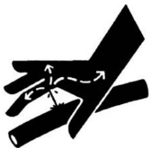
- Escaping hydraulic fluid under pressure has sufficient force to penetrate the skin causing serious personal injury. Before disconnecting lines, be sure to relieve all pressure. Before applying pressure to the system, make sure all connections are tight and that lines, pipes, and hoses are not damaged.
natural_image
Abstract black-and-white diagram showing two intersecting diagonal lines with arrows indicating direction (no text or symbols)1BAACAAAP010B
- Fluid escaping from pinholes may be invisible. Use a piece of cardboard or wood to search for suspected leaks: do not use hands. Use safety goggles or other eye protection.
If injured by escaping fluid, see a medical doctor at once. Serious infection or reaction will result if proper medical treatment is not administered immediately. This fluid can produce gangrene or severe allergic reaction.

(1) Cardboard
(2) Hydraulic line
(3) Magnifying glass
-
Do not make adjustments or repairs with the engine running.
-
Keep machine free of grass, leaves, or other debris build-up.
-
Do not change the engine governor setting or overspeed the engine.
-
Do not run a machine inside a closed area.
-
Mower blades are sharp and can cut your hands. Wrap the blade(s) or wear gloves, and use extra caution when servicing them.
-
Keep nuts and bolts, especially blade attachment bolts, tight and keep equipment in good condition.
-
Never tamper with safety devices. Check their operation for proper function regularly.
-
Waste products such as used oil, fuel, coolant, brake fluid, and batteries, can harm the environment, people, pets and wildlife. Please dispose of properly.
-
Do not use beverage containers for waste fluids or other products. Someone, particularly children, may drink them by mistake.
-
Securely support machine or any machine elements with stands or suitable blocking before working underneath. For your safety do not rely or hydraulically supported devices, they may leak down, suddenly drop or be accidentally lowered.
-
See your local Recycling Center or KUBOTA Dealer to learn how to recycle or get rid of waste products.
● A Material Safety Data Sheet (MSDS) provides specific details on chemical products; physical and health hazards, safety procedures, and emergency response techniques. The seller of the chemical products used with your machine is responsible for providing the MSDS for that product upon request.
◆Storage
- Keep the machine and supply of fuel in locked storage and remove the ignition key to prevent children or others from playing or tampering with them.
- To avoid sparks from an accidental short circuit, always disconnect the battery's ground cable (-) first and reconnect it last.
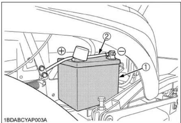
(1) Battery
(2) Ground cable
(+): Positive terminal
(-): Negative terminal
- To avoid the danger of exhaust fume poisoning, do not operate the engine in a closed building without adequate ventilation.
- To reduce fire hazards, clean the machine thoroughly before storage. Dry grass and leaves around the engine and muffler may ignite.
7. DANGER, WARNING AND CAUTION LABELS
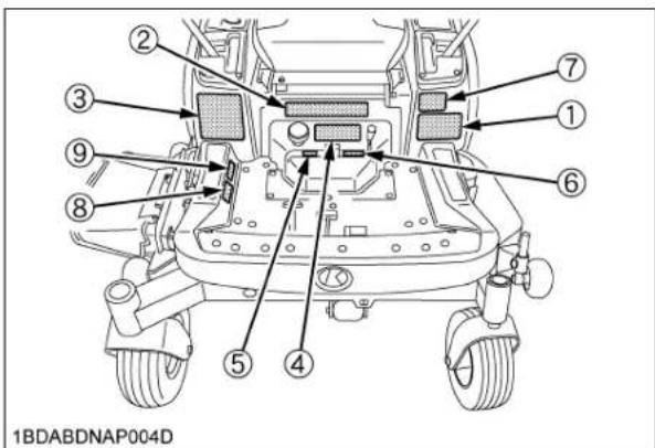
(1) Part No. K3181-6585-1

1BDABCQAP093A
(2) Part No. K3271-6585-1

1BDABCYAP063A
(3) Part No. K3271-6581-1
(6) Part No. K3272-6569-1

1BDABDNAP068A
(4) Part No. K3272-6587-1

(5) Part No. K3131-6568-1

1BDABDEAP024A
(7) Part No. K3271-6571-1

(8) Part No. K3441-6598-1

(9) Part No. K3441-6596-1
1BDABENAP115A
1BDABDNAP062A

(1) Part No. K3271-6583-1

(3) Part No. K3271-6562-2
Gasoline fuel only No fire

1BDABCYAP068A
(2) Part No. K3272-6532-1

1BDABDNAP069A
(4) Part No. K3272-2481-1

(1) Part No. K3181-6564-1
1BDABCQAP100A
(2) Part No. K3181-6563-1
1BDABCQAP101A

(3) Part No. K3282-6566-1

(4) Part No. K3181-6565-1

(5) Part No. K3282-6573-1

1BDABDNAP071A
(6) Part No. K3282-6574-1


(1) Part No. K3271-6586-1

1BDABBSAP0110
(2) Part No. K2601-9616-2
PROPOSITION 65 WARNING: Battery posts, terminals and related accessories contain lead and lead compounds, chemicals known to the State of California to cause cancer and reproductive harm. Batteries also contain other chemicals known to the State of California to cause cancer. WASH HANDS AFTER HANDLING.
(3) Part No. K1221-6113-2

DANGER / POISON
● SHIELD EYES
EXPLOSIVE GASES can cause
blindness or injury.
● NO SPARKS / FLAMES / SMOKING
● SULFURIC ACID can cause blindness or severe burns.
● Flush eyes immediately with water.
● Get medical help fast.
1AYAACPAP081A
1BDABDNAP065A

SAFE OPERATION-10
![[RCK48S] ① ② 1BDABCYAP040B](/content/2026/06/1369073/images/228ef7b975d1c45552bf62b388d3062978ea951dd700dcb4ed3fbe2bf2c02e0e.jpg)
![[RCK48P, RCK54P] ⑤ ④ ③ DO NOT REMOVE DO NOT REMOVE 1BDABDNAP008A](/content/2026/06/1369073/images/3196a93b0116f47c2c52d2070c9df9c8fb72ac4c0f891b1db2b825516a3a328c.jpg)
![[RCK60P] ③ ⑤④ 1BDABDMAP006A](/content/2026/06/1369073/images/b86d9bbdd716e15b4745b6b3cf798e2989e0ca6c4e745b489060d36e925377a9.jpg)
(1) Part No. K5617-7311-1

1BDABBSAP0030
(2) Part No. K5617-7312-1

1BDABBSAP0020
(3) Part No. K5681-7312-2
1BDACAEAP015B
1BDABDNAP066A
(4) Part No. K5681-7311-2

1BDACAEAP016B
(5) Part No. K5681-7310-1

1BDACAEAP017B
8. CARE OF DANGER, WARNING, AND CAUTION LABELS
- Keep danger, warning and caution labels clean and free from obstructing material.
- Clean danger, warning and caution labels with soap and water, and dry with a soft cloth.
- Replace damaged or missing danger, warning and caution labels with new labels from your local KUBOTA Dealer.
- If a component with danger, warning and caution label(s) affixed is replaced with new part, make sure new label(s) is (are) attached in the same location(s) as the replaced component.
- Mount new danger, warning and caution labels by applying on a clean dry surface and pressing any bubbles to outside edge.
SERVICING OF MACHINE
After reading this manual thoroughly, you will find that you can do some of the regular maintenance yourself. Your dealer is interested in helping you get the best performance from your new machine and wants to help you get the most value from it. When in need of parts or major service, be sure to see your KUBOTA Dealer. When in need of parts, be prepared to give your dealer the machine, engine and mower serial numbers.
Locate the serial numbers now and record them in the space provided.
| Type Serial No. | ||
| Machine | ||
| Engine | ||
| Mower | ||
| Date of Purchase | ||
| Name of Dealer | ||
| (To be filled in by purchaser) | ||

(1) Machine identification plate
(2) Machine serial No.

(1) Engine serial No.
![[RCK48S] 1BDABCYAP040A](/content/2026/06/1369073/images/ca89beaa34aa60fb123f2811227ade979b46218c1abbabb3c6df05bb4e09e623.jpg)
(1) Mower identification plate
(2) Mower serial No.
![[RCK48P] 1BDABDNAP008B](/content/2026/06/1369073/images/c9fe2fbd8d90b94c0cbd432546d46fd388bdec8ef56c4c6cae624269f1433934.jpg)
(1) Mower identification plate
(2) Mower serial No.
![[RCK54P] DO NOT REMOVE 1BDABDNAP011A](/content/2026/06/1369073/images/02b8157057d2355717796096808666c2894ce6004a792a087a95a8efde95f8d2.jpg)
(1) Mower identification plate
(2) Mower serial No.
![[RCK60P] 1BDABDMAP006B](/content/2026/06/1369073/images/8bb9cc23f7080d0524cf3b7b53d8d279f1a093b82379dde87a25c419c80404da.jpg)
(1) Mower identification plate
(2) Mower serial No.

(1) ROPS serial No.
SPECIFICATIONS
| Model ZG222SA ZG222A ZG227A ZG227LA | ||||||
| Engine | Model KGZ770-MA3 KGZ770-MA2 | |||||
| Max. engine power (Gross) kW (HP) 15.7 (21.1) (*)1) 19.4 (26.0) (*)1) | ||||||
| Type Air-cooled gasoline engine | ||||||
| Number of cylinders 2 (V-Twin) | ||||||
| Bore and stroke mm (in.) | 84.2 x 69(3.31 x 2.72) | |||||
| Total displacement cm (cu. in.) | 3 | 768 (46.9) | ||||
| Rated revolution | rpm | 3200 | ||||
| Fuel | Automobile unleaded or regular gasoline | |||||
| Starter | Electric starter with battery | |||||
| Lubrication | Full pressure lubrication | |||||
| Cooling | Forced air cooled | |||||
| Battery | U1L-10 (12 V, RC: 22 min, CCA: 300, CA: 365) | |||||
| Capacities | Fuel tank | L (U.S.gals.) | 27 (7.1) | |||
| Engine crankcase(with filter) | L (U.S.qts.) | 1.8 (1.9) | 2.0 (2.1) | |||
| Transmission case includingRear axle gear case | L (U.S.qts.) | 7.5 (7.9) (*3) | ||||
| Dimensions | Overall length | mm (in.) | 2096 (82.5) | 2126 (83.7) | ||
| Overall widthw/o mower deck | mm (in.) | 1210 (47.7) | ||||
| Overallheight | With ROPSupright | mm (in.) | 1775 (69.9) | |||
| With ROPSfolded | mm (in.) | 1340 (52.8) | ||||
| Wheelbase | mm (in.) | 1295 (51.0) | 1325 (52.2) | |||
| Min. ground clearance | mm (in.) | 130 (5.12)W/48", W/48" S | 130 (5.12)W/54" | 130 (5.12)W/60" | ||
| Tread | Front | mm (in.) | 870 (34.3) | 905 (35.6) | ||
| Rear | mm (in.) | 930 (36.6) | ||||
| Weight(W/MOWER DECK) | kg (lbs.) | 500 (1102) with48" S | 530 (1168) with 48" | 540 (1190) with 54" | ||
| Travelingsystem | Tires | Front | 13 x 5.0 - 6 (4PR) Rib | |||
| Rear | 23 x 10.5 - 12 (4PR) Turf | |||||
| Travelingspeeds *2 | Forward | mph (km/h) | 0 to 9.0 (0 to 14.5) | |||
| Reverse | mph (km/h) | 0 to 5.0 (0 to 8.0) | ||||
| Steering | 2 - Hand levers | |||||
| Transmission | 2 - HST w / Gear | |||||
| Parking brake | Wet multi disk / Foot applied, released | |||||
| Min. turning radius | mm (in.) | 0 (0) | ||||
| PTO | Revolution | 1 speed(2530 rpm at 3200 engine rpm) | ||||
| Drive system Shaft drive, KUBOTA 10 tooth involute spline | ||||||
| Clutch type Wet multi disks | ||||||
| PTO brake Wet single disk | ||||||
(Specifications and design subject to change without notice)
NOTE:
*1: Power (HP) specifications for individual gasoline engine models are rated pursuant to Society of Automobile Engineers (SAE) J1940 based on gross output testing performed in accordance with SAE J1995 without the air cleaner and muffler.
*2: At 3200 engine rpm
*3: Oil amount when the oil level is at the upper level.
| Model RCK48S-222Z RCK48P-222Z RCK54P-227Z RCK60P-227Z | |||||||
| PRO Commercial Deck (Fabricated deck) | Suitable machine ZG222SA ZG222A ZG227A ZG227LA | ||||||
| Mounting method Quick joint, Parallel linkage | |||||||
| Adjustment of cutting height Dial gauge | |||||||
| Cutting width mm (in.) 1225 (48) 1375 (54) 1524 (60) | |||||||
| Cutting height mm (in.) 25 to 127 (1.0 to 5.0) | |||||||
| Weight (Approx.) kg (lbs.) 83 (183) 106 (234) 119 (262) 134 (295) | |||||||
| Blade spindle speed | r/s (rpm) | 58.0 (3480) *1 | 64.8 (3890) *1 | 58.0 (3480) *1 | 56 (3360) *1 | ||
| Blade tip velocity | m/s (fpm) | 77.3 (15200) *1 | 86.4 (17000) *1 | 86.6 (17000) *1 | 92 (18100) *1 | ||
| Blade length | mm (in.) | 424 (16.7) | 475 (18.7) | 523 (20.6) | |||
| Number of blades | 3 | ||||||
| Dimensions | Total length | mm (in.) | 890 (35.0) | 880 (34.6) | 925 (36.4) | 963 (37.9) | |
| Total width | mm (in.) | 1550 (61.0) | 1552 (61.1) | 1710 (67.3) | 1911 (75.2) | ||
| Total height | mm (in.) | 340 (13.3) | |||||
*1: Engine Max rpm
6 IMPLEMENT LIMITATIONS
IMPLEMENT LIMITATIONS
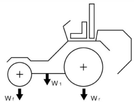
The KUBOTA Machine has been thoroughly tested for proper performance with implements sold or approved by KUBOTA. Use with implements which are not sold or approved by KUBOTA and which exceed the maximum specifications listed below, or which are otherwise unfit for use with the KUBOTA Machine may result in malfunctions or failures of the machine, damage to other property and injury to the operator or others. [Any malfunctions or failures of the machine resulting from use with improper implements are not covered by the warranty.]
| Maximum loading weight | Implement weight W1 | Maximum total weight | ||
| Front axle Wf Rear | axle Wr | |||
| ZG222SA, ZG222A | 145 kg (319 lbs.) 510 | kg (1124 lbs.) 140 kg (308 lbs.) 655 kg (1444 lbs.) | ||
| ZG227A, ZG227LA | ||||
1BDABCQAP132A
INSTRUMENT PANEL AND CONTROLS
ILLUSTRATED CONTENTS ILLUSTRATED CONTENTS
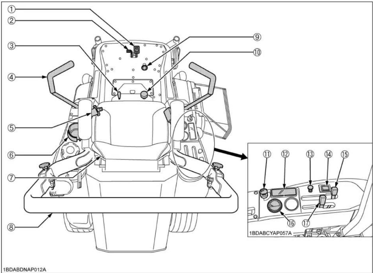
(1) Parking brake pedal.... 11, 22 (10) Cutting height control dial.... 28
(2) Parking brake lock pedal.... 11, 22 (11) Key switch.... 13
(3) Lift lock lever.... 27 (12) Easy checker (TM).... 14
(4) Motion control lever.... 11, 23 (13) Choke knob.... 13
(5) Seat belt.... 21 (14) Hour meter.... 15
(6) Cup holder.... - (15) PTO lever.... 31
(7) Operator's seat.... 21 (16) Fuel gauge.... 14
(8) ROPS.... 19 (17) Throttle lever.... 22
(9) Hydraulic lift control pedal.... 21
![[RCK60P] 1BDABDMAP006C](/content/2026/06/1369073/images/d361a1e5948c055fed09aa5bce0bf1917604554ac29b1a8a4ddf567dc4b4d677.jpg)
ILLUSTRATED CONTENTS
(1) Anti-scalp roller (Front, pin shift type)..... 28
(2) Anti-scalp roller (Rear, bolt shift type)..... 28
![[RCK48S] 1BDABCYAP040D](/content/2026/06/1369073/images/a08ba209e356cb4aef6f3d27a6c389fb8433be5ba0aeff71792e86cdfb520603.jpg)
ILLUSTRATED CONTENTS
(1) Anti-scalp roller (Front, bolt shift type)..... 28
(2) Anti-scalp roller (Rear, bolt shift type)..... 28
![[RCK48P, RCK54P] ① ① ② ② DO NOT REMOVE 1BDABDNAP011B](/content/2026/06/1369073/images/9564dad01fd89e61aee3915ef1f55e75fc920c5e261c87755efa3b833a780729.jpg)
ILLUSTRATED CONTENTS
(1) Anti-scalp roller (Front, bolt shift type)..... 28
(2) Anti-scalp roller (Rear, bolt shift type)..... 28
MOWER MOUNTING
MOUNTING THE MOWER DECK

CAUTION
To avoid personal injury:
● Park the machine on a firm and level surface.
- Apply the parking brake.
- Stop the engine and remove the key.
- Before mounting the mower deck, raise the lift links to the full up position. (See "STARTING" in "OPERATING THE MACHINE" section.)
- Adjust the cutting height control dial to 1 in. position.
- Go backward so that right and left rear tires would be on the board 40 mm (1.57 in.) high.

H: 40 mm (1.57 in.) W: 300 mm (11.8 in.)
IMPORTANT :
- Use a board more than 300 mm (11.8 in.) wide and 1400 mm (55.1 in.) long.
● Make sure that right and left rear tires are firm on the board. - Change the direction of the front tires as shown in the figure.
- Place the mower deck at the right side of the machine.

H: 40 mm (1.57 in.)
W: 300 mm (11.8 in.)
L: 1400 mm (55.1 in.)
- Slide the mower deck under the machine, and make sure that the mower gear case is placed properly in the center of the machine.
NOTE :
● [Only for RCK60P]
For easy installation set the anti scalp roller as shown below.
RCK60P: Two places front

(1) Anti scalp roller (Front, pin shift type)
(2) Anti scalp roller (Rear, bolt shift type)
- Adjust the lift pedal to the lowest position and pull down the lift links.
- Attach the lift links to the mower deck with attaching hardware.

(1) Lift link
(2) Clevis pin, Plain washer, Snap ring
- Install universal joint.
Pull back the coupler of the universal joint.
Push the universal joint onto the PTO shaft until the coupler locks.
IMPORTANT :
● Tug the universal joint backward and forward to make sure it is locked securely.


(1) Universal joint
(2) Coupler
(A) "PULL"
- After mounting the mower, check the mower level. If necessary, adjust the mower level and anti-scalp rollers.
ADJUSTING THE MOWER
See "OPERATING THE MOWER" and "ADJUSTMENT" section.
DISMOUNTING THE MOWER DECK
For dismounting the mower deck, reverse the above procedures.
To avoid personal injury:
- Read "SAFE OPERATION" in the front of this manual.
- Read the danger, warning and caution labels located on the machine.
● To avoid danger of exhaust fume poisoning, do not operate the engine in a closed building without proper ventilation.
● Never start the engine while standing on the ground. Start the engine only from operator's seat.
MOUNT AND DISMOUNT MACHINE SAFELY
DO NOT step on either side of the mower deck when mounting and dismounting the machine. When mounting the machine from either side, step over the mower deck.

natural_image
Line drawing of a person operating a small wheeled vehicle with wheels, no text or symbols presentSTARTING THE ENGINE
- Sit on the operator's seat.
- Apply the parking brake.
To apply the parking brake:
Depress the parking brake pedal firmly with your right foot and the parking brake lock pedal simultaneously with your left foot. Then release the parking brake pedal while holding the parking brake lock pedal down.

(1) Parking brake lock pedal
(2) Parking brake pedal
(A) "DEPRESS"
To release the parking brake:
Depress the brake pedal and release slowly with your right foot without pressing the parking brake lock pedal.
3. Make sure that the PTO lever is in the "DISENGAGED" (OFF) position.

(1) PTO lever "ENGAGED" (ON)
"DISENGAGED" (OFF)
4. Place the motion control levers in the "NEUTRAL LOCK" position.

(1) Motion control lever (LH)
(A) "NEUTRAL LOCK" Position
(2) Motion control lever (RH)
(B) "NEUTRAL" Position (held by hands)
(C) "CREEP" Position (hands off)
(D) "FORWARD"
(E) "REVERSE"
5. Release the hydraulic lift control pedal to the "DOWN" position.

(1) Hydraulic lift control pedal Depressing "UP"
Release: "DOWN"
6. Set the throttle lever as follows.
- If the engine is cold:
Pull the choke knob out.
- If the engine is warm:
Place the throttle control lever midway between the "SLOW" and the "FAST" positions.

(1) Throttle lever
"FAST"
(2) Choke knob
"SLOW"
(A) Pull out: "ON" position
(B) Push in: "OFF" position
7. Insert the key into the key switch. Turn the key switch to the "START" position and release the key to the "ON" position when the engine starts.
IMPORTANT :
- Because of the start interlocks, the engine can not be started except when the PTO clutch is disengaged (OFF), the parking brake lock pedal is applied, motion control levers are in "NEUTRAL LOCK" position and the operator is sitting on the seat.
■Throttle Lever and Choke Knob
Pulling the throttle lever backward decreases the engine speed and pushing it forward increases the engine speed.
[For a Cold Engine]
Always pull the choke knob out to the "ON" position to start the engine in cold conditions.
Gradually return the choke control to the "OFF" position after the engine starts and warms up.
The engine/equipment may be operated during the warm-up period, but it may be necessary to leave the choke partially on until the engine warms up.
[For a Warm Engine]
Always push the choke knob in to the "OFF" position after the engine starts.
■Key Switch

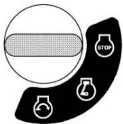
OFF...... The position where the key can be inserted into or removed from the key switch. [When the key is turned to this position, the engine shuts off.]

ON...... The engine keeps running.

START...... Apply the parking brake and turn the key switch to this position to start the engine.
1BDABBSAP060A
: "OFF"
②: "ON"
: "START"
IMPORTANT :
- Do not use starting fluid or ether.
● To protect the battery and the starter, make sure that the starter is not continuously turned for more than 10 seconds at a time. If the engine does not start, allow 60 seconds cool down period between starting attempts. - If the starter does not turn the engine over, shut off the starter immediately. Do not make further attempts to start the engine until the condition is corrected. Do not jump start using another battery. Consult your local KUBOTA dealer.
- Do not turn the key switch to the "START" position while the engine is running.
- When the temperature is below 0 (32), then the engine at medium speed to warm up the lubricant of the engine and the transmission for at least 10 minutes. If the machine is operated before the lubricant is warm enough, the machine life will be shortened.
- Do not operate the machine under full load until it is sufficiently warmed up 2 or 3 minutes for temperature above 0 (G2). °F
-
When the ambient temperature is less than -15 °C (5°F remove the battery from the machine and store it somewhere warm until the next operation.
-
Make sure that the Easy Checker (TM) lights have gone off. If the light is still on, immediately stop the engine and check the remedy following the instruction. (See "CHECK DURING OPERATING" in "OPERATING THE ENGINE" section.)
-
Warm the engine by running at medium speed.
CHECK DURING OPERATING
While operating, make the following checks to see that all the parts are functioning normally.
■Immediately Stop the Engine if:
● The engine suddenly slows down or accelerates.
● Unusual noises are suddenly heard.
● Exhaust fumes suddenly become discolored.
■ Easy Checker (TM)
If the warning lamps in the Easy Checker (TM) come on during operation, stop the engine immediately, and find the cause as shown below.
Never operate the machine while Easy Checker (TM) lamp is "ON".

(1) Easy checker (TM)
Engine oil pressure
If the oil pressure in the engine goes below the prescribed level, the warning lamp in the Easy Checker (TM) will come on.
If this should happen during operation, stop the engine immediately and check level of engine oil.
■Fuel Gauge
Be careful not to empty the fuel tank. Otherwise air may enter the fuel system.
If this should happen, the fuel system should be bled. (See "SERVICE AS REQUIRED" in "PERIODIC SERVICE" section.)

(1) Fuel gauge (E) "EMPTY"
(F) "FULL"
IMPORTANT :
- Do not refuel over "F". Fill the tank only to the bottom of the filler neck in the fuel tank.
● Fill the fuel on a level ground.
Fuel Pump
This fuel pump has a limit drive function.
NOTE :
- When the key is in the "OFF" position: It does not work.
- When you turn the key clockwise one notch, before the engine starts: It works for about 15 seconds.
- Keep the key in this position, before the engine starts. It will stop working after 15 seconds. And to reset the timer, keep the key in the "OFF" position for about 60 seconds.
- When the engine is running: It works normally.
■Hour Meter
This meter gives readings for the hours the machine has been operated for.
NOTE :
- As the hour meter works electrically, it starts to work when the key switch is turned to "ON", regardless of the engine running or not.

(1) Hour meter
COLD WEATHER STARTING
If the ambient temperature is below 0°32) and the engine is very cold, start it in the following manner:
-
Pull the choke knob out.
-
Turn the key switch to the START (" " position.
-
Operate the starter 5 seconds.
- If the engine does not start, wait 10 seconds.
-
Repeat this procedure until the engine starts.
-
When the engine starts, release the key to the "ON" ("") position.
-
Place the throttle lever midway between the "SLOW" and the "FAST" positions.
WARMING UP

CAUTION
To avoid personal injury:
- Be sure to apply the parking brake during warm-up.
For 5 minutes after engine start-up, allow the engine to warm up without applying any load. This is to allow oil to reach every engine part. If load should be applied to the engine without this warm-up period, the troubles such as seizure, breakage or premature wear may develop.
■Warm-up and Transmission Oil in the Low Temperature Range
Hydraulic oil serves as transmission oil. In cold weather, the oil may be cold with increased viscosity. This can cause delayed oil circulation or abnormally low hydraulic pressure for some time after engine start-up. This in turn can result in a trouble in the hydraulic system or a damage to the hydraulic clutch.
To prevent the above, observe the following instructions: Warm up the engine at about 50% of rated rpm according to the table below:
| Ambient temperature Warm-up time requirement | |
| Higher than 0 (32) Approx. 5 minutes | |
| -10 to 0 (14 to 32) 5 to 10 minutes | |
| -20 to -10 (4-4 to 14) 10 to 15 minutes | |
| Below -20 (4) More than 15 minutes |
IMPORTANT :
- Do not operate unless the engine is well warmed up. If operation is attempted while the engine is still cold, the hydraulic mechanism will not function properly and its service life will be shortened.
- If noises are heard after the hydraulic control lever has been activated and the implement is lifting, the hydraulic mechanism is not adjusted properly. Unless corrected, the unit will be damaged. Contact your local KUBOTA Dealer for adjustment.
JUMP STARTING

WARNING
To avoid serious injury or death:
● Battery gases can explode. Keep cigarettes, sparks, and flames away from battery.
- If the machine battery is frozen, do not jump start the engine.
- Do not connect the other end of negative jumper cable to the negative terminal of the machine battery.
When jump starting engine, follow the instructions below to start the engine safely.
- Bring a helper vehicle with a battery of the same voltage as a disabled machine within easy cable reach. "THE VEHICLES MUST NOT TOUCH".
- Apply the parking brakes of both vehicles and put the shift levers in neutral. Shut the engine off.
- Put on safety goggles and rubber gloves.
- Ensure vent caps are securely in place (if equipped).
- Attach the red clamp to the positive (red, (+) or pos.) terminal of the dead battery and clamp the other end of the same cable to the positive (red, (+) or pos.) terminal of the helper battery.
- Clamp the other cable to the negative (black, (-) or neg.) terminal of the helper battery.
- Clamp the other end to the engine block or the frame of the disabled machine as far from the dead battery as possible.
- Start the helper vehicle and let its engine run for a few moments. Start the disabled machine.
- Disconnect the jumper cables in the exact reverse order of attachment. (Steps 7, 6 and 5)

(1) Dead battery
(2) Jumper cables
(3) Engine block or frame
(4) Helper battery
Connect cables in numerical order.
Disconnect in reverse order after use.
IMPORTANT :
● This machine has a 12 volt negative (-) ground starting system.
- Use only same voltage for jump starting.
- Use of a higher voltage source on a machine could result in severe damage to the machine electrical system.
Use only matching voltage source when "jump-starting" a low or dead battery condition.
STOPPING THE ENGINE
- After slowing the engine to half speed, turn the key switch to the "OFF" position.
- Remove the key.
- Do not leave the key switch "ON" (key in the "ON" position) as the battery will discharge when the engine is not running.
- Apply the parking brake.
- Turn the carburetor fuel valve to "STOP" (CLOSE) position.

(1) Carburetor fuel valve (A) "STOP" (CLOSE)
(B) "RUN" (OPEN)
(C) "DRAIN"
IMPORTANT :
- Do not stop the engine when the machine is on an incline for a long time. The engine oil may go into the carburetor and the muffler through the valve system.
- Place the throttle control lever in the half speed position to help prevent the engine from backfiring before stopping the engine.
■Engine Stop (By manual)
The engine stops when the key switch is turned off. If the engine does not stop, make sure the motion control levers are in "NEUTRAL LOCK" position, the PTO lever is "OFF", the mower lowered to the ground, apply the parking brake, and confirm it is set, then carefully get off the machine. Turn the carburetor fuel valve to "STOP" (CLOSE) position and wait until the engine stops. Then contact your local KUBOTA Dealer immediately.
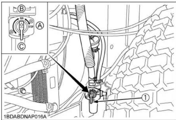
(1) Carburetor fuel valve (A) "STOP" (CLOSE)
(B) "RUN" (OPEN)
(C) "DRAIN"

CAUTION
To avoid personal injury:
- Do not operate the machine until the engine stop system is repaired.
How a new machine is operated and maintained determines the life of the machine.
A new machine just off the factory production line has been, of course, tested, but the various parts are not accustomed to each other, so care should be taken to operate the machine for the first 50 hours at a slower speed and avoid excessive work or operation until the various parts become "broken-in." The manner in which the machine is handled during the "breaking-in" period greatly affects the life of your machine. Therefore, to obtain the maximum performance and the longest life of the machine, it is very important to properly break-in your machine. In handling a new machine, the following precautions should be observed.
■Changing Lubricating Oil for New Machines
The lubricating oil is especially important in the case of a new machine. The various parts are not "broken-in" and are not accustomed to each other; small metal grit may develop during the operation of the machine; and this may wear out or damage the parts. Therefore, care should be taken to change the lubricating oil a little earlier than would ordinarily be required.
For further details of change interval hours.
(See "SERVICE INTERVALS" in "MAINTENANCE" section.)
■Engine Break-in
After the first 50 hours of operation, change the engine oil and filter. (See "EVERY 100 HOURS" "EVERY 200 HOURS" in "PERIODIC SERVICE" section.)
■Machine Break-in
After the first 400 hours of operation, change the transmission fluid. (See "EVERY 400 HOURS" in "PERIODIC SERVICE" section.)
After the first 50 hours of operation, change the transmission oil filter cartridge. (See "EVERY 200 HOURS" in "PERIODIC SERVICE" section.)

DANGER
To avoid serious injury or death:
- Do not operate the mower without the discharge chute in the down position.

WARNING
To avoid serious injury or death:
- The machine relies upon the engine driven transmission for speed, direction and motion control. If the engine is not running, the machine cannot be driven or controlled. If the engine stops when operating on a slope, apply the parking brake immediately to prevent machine runaway.
- Do not allow any person other than the driver to ride on the machine.
- Do not drive the machine close to the edges of ditches or banks which may collapse under the weight of the machine, especially when the ground is loose or wet.
- When turning the machine, be sure to reduce the travel speed and operate motion control levers carefully.
- To avoid tip over, operate across slopes, not up and down. Avoid sudden starts and stops on slopes. Slow down, and use extra caution when changing direction on a slope. Park the machine on a firm and level surface.
- Watch where you are going at all times. Watch for and avoid obstacles. Be alert at curbs, near trees, and other obstructions and hidden hazards.
- Do not mow near drop-offs, ditches or embankments. The mower could turn over if a wheel is over the edge of cliff or ditch, or if an edge caves in.
- Do not drive machine on streets or highways. Watch for traffic when you cross roads or operate near roads.
- Look to the rear before and when backing. Make sure the area immediately behind you is clear of obstructions or holes and small children. Use extra caution when machine is equipped with Grass Catcher.
- Keep bystanders especially children and animals away from the mowing area.

CAUTION
To avoid personal injury:
- Clear the work area of objects which might be picked up and thrown by blades.
- Do not direct the opening of the chute at bystanders or animals. Ejected objects may cause injury. Plan your mowing carefully before starting operation.
- Be sure to disengage the PTO and sit on the operator's seat before starting the engine.
OPERATING FOLDABLE ROPS

CAUTION
To avoid personal injury:
- When raising or folding the ROPS, apply parking brake, stop the engine and remove the key.
Always perform function from a stable position to the rear of the machine.
●Fold the ROPS down only when absolutely necessary and fold it up and lock it again as soon as possible.
● Before proceeding to fold the ROPS, check for any possible interference with installed implements and attachments.
If interference occurs, contact your KUBOTA Dealer.
■To Fold the ROPS
- Unscrew the knob bolts 1 to 2 turns.
- Remove both lock pins.

(1) Lock pin
(2) Hair pin
(3) Knob bolt
- Fold the ROPS.

CAUTION
To avoid personal injury:
● Hold the ROPS tightly with both hands and fold the ROPS slowly and carefully.

(1) ROPS
- Align lock pin holes and insert both lock pins and secure them with the hair pins.

CAUTION
To avoid personal injury:
● Make sure that both lock pins are properly installed and secured with the hair pins.

(1) Lock pin
(2) Hair pin
■To Raise the ROPS to Upright Position
- Remove both hair pins and lock pins.

(1) Lock pin
(2) Hair pin
- Raise ROPS to the upright position.

CAUTION
To avoid personal injury:
● Hold the ROPS tightly with both hands and raise the ROPS slowly and carefully.
- Align lock pin holes, insert both lock pins and secure them with the hair pins.
- Tighten the knob bolts slightly.

CAUTION
To avoid personal injury:
● Make sure that both lock pins are properly installed as soon as the ROPS is in the upright position and secured with the hair pins.

(1) Lock pin
(2) Hair pin
(3) Knob bolt
■Adjustment of Foldable ROPS
- Adjust free fall of the ROPS upper frame regularly.
- If you feel less friction when folding the ROPS, tighten the nut (1) until you feel the right friction in the movement and then replace the hair pin.
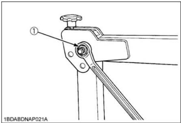
(1) Nut
STARTING
1. Adjust the operator's position and engage the seat belt.
Operator's Seat

CAUTION
To avoid personal injury:
● Make adjustments to the seat only while the machine is stopped.
● Make sure that the seat is completely secured after each adjustment.
- Do not allow any person other than the driver to ride on the machine.

(1) Armrest
(2) Fore-aft adjusting handle
◆How to adjust the operator's seat
- Fore-aft adjust
Pull the seat adjusting lever and slide the seat.
IMPORTANT :
● After adjusting the operator's seat, be sure to check to see that the seat is securely locked.
Seat Belt

CAUTION
To avoid personal injury:
● Always use the seat belt when the ROPS is installed.
- Do not use the seat belt if a foldable ROPS is down or there is no ROPS.
Adjust the seat belt for proper fit and connect to the buckle. The seat belt is auto-locking retractable type.
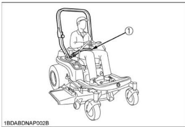
(1) Seat belt
2. Raise the implement.
■Hydraulic Lift Control Pedal
The hydraulic lift control pedal is used to raise the mower. To raise the mower, keep depressing the pedal. To lower it, release the pedal.

(1) Hydraulic lift control pedal "DOWN": Release the pedal
"UP": Keep depressing the pedal
IMPORTANT :
- Do not operate until the engine is warmed up. If operation is attempted when the engine is still cold, the hydraulic system may be damaged.
- Do not operate at slow engine rpm. Move the throttle lever above 1/2.
- If noises are heard when implement is lifting after the hydraulic lift control pedal has been activated, the hydraulic mechanism is not adjusted properly. Contact your local KUBOTA Dealer for adjustment.
- Do not depress the hydraulic lift control pedal continuously while operating the machine.
3. Accelerate the engine.
Throttle Lever
Moving the throttle lever backward decreases the engine speed and moving it forward increases the engine speed.

(1) Throttle lever "INCREASE"

"DECREASE"
4. Unlock the parking brake.
■Parking Brake Pedal
To release the parking brake:
Depress the brake pedal and release slowly with your right foot, without pressing the parking brake lock pedal.

(1) Parking brake pedal
(2) Parking brake lock pedal
(A) "DEPRESS"
5. Operate the machine.
■Motion Control Lever

CAUTION
To avoid personal injury:
- Understand how to use the motion control levers and practice in an unrestricted area at a little more than an idle speed without the mower engaged until becoming proficient in the operation of the machine.
- Do not move motion control levers from forward to reverse or reverse to forward position rapidly. Sudden direction changes could cause loss of control or damage to the machine or property.
- Do not make sharp turns at high speeds. Fast and sharp turns could cause loss of control.
- Motion control levers must be in "NEUTRAL LOCK" position to safely enter and exit the operator's seat or to carry out maintenance and safety checks.
● This machine can make sharp turns. Always make sure your intended path is clear of obstructions or persons.
NOTE :
- To make restarting on the slopes easier, this machine has the "CREEP" position.
If you release hand pressure from the levers in the operating position, the levers move to the "CREEP" position automatically.
Stop position
◆Neutral lock position
- Forward and reverse movement of the motion control levers are prevented when levers are in "NEUTRAL LOCK" position. (Engine can only be started with levers in this position.)
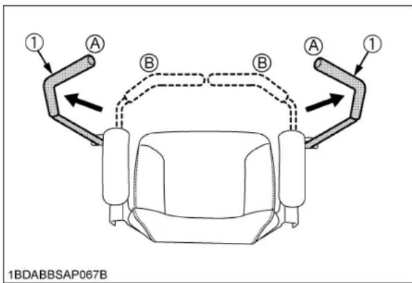
(1) Motion control levers (A) "NEUTRAL LOCK" position
(B) "NEUTRAL" position (held by hand)
Operating position
Machine speed and steering is controlled by the motion control levers, when the engine is running and the parking brake is released.

CAUTION
To avoid personal injury:
- No control is provided by the motion control levers when the engine is off.
Neutral position
- Grasp the motion control levers and move them inward from the "NEUTRAL LOCK" position so that the machine is in "NEUTRAL". (Engine cannot be restarted.)
◆Creep position (Moves the machine slowly forward)
- To make restarting on the slopes easier, this machine has the "CREEP" position.
- If hand pressure is released from the motion control levers after moving them from the "NEUTRAL LOCK" position with the engine running, the levers move to the "CREEP" forward position by spring pressure. When hand pressure is released from the motion control levers while in the reverse position with the engine running, the levers will return through neutral to the "CREEP" forward position by spring pressure.
● The machine moves forward at creep speed, when the levers are in the "CREEP" position.
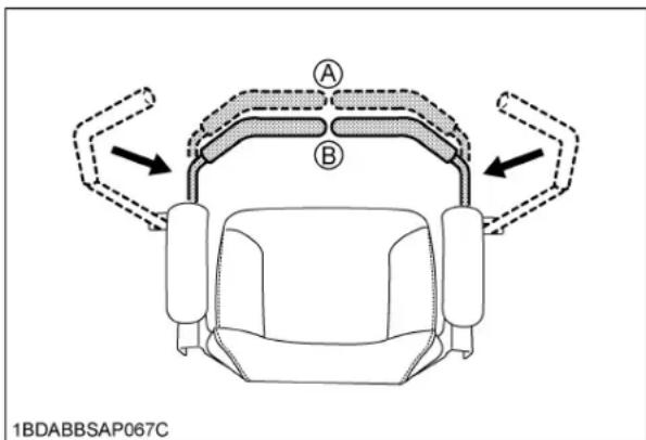
(1) Motion control levers (A) "CREEP" position
(B) "NEUTRAL" position (held by hand)
◆Forward and Reverse Motion:
- Move throttle lever to the "FAST" position.
- Release the parking brake.
-
Move both motion control levers from the "NEUTRAL LOCK" position inward to the "NEUTRAL" position.
-
Push the control levers slowly forward to begin forward motion.
To move reverse:
Pull both control levers slowly rearward at the same time to begin reverse motion.
To stop:
Move by hand and hold both motion control levers to the "NEUTRAL" position until the machine comes to a stop.

CAUTION
To avoid personal injury:
● The motion control lever adjustment is important to ensure the machine operates properly.
NOTE :
- The motion control linkages are adjustable. If adjustment is required, see "ADJUSTMENT" section. We recommend you to contact your local KUBOTA Dealer.
◆Re-start on the slopes

CAUTION
To avoid personal injury:
- Do not stop or change directions on the slopes. These operations could cause loss of the machine traction or control. Starting procedure on the slopes is different from the usual start mode on a flat surface, understand how to re-start on the slopes and use extra caution.
If a situation occurs where it is necessary to stop and restart on a slope, refer to the following operational steps.
How to re-start on the slopes:
- Firmly apply parking brake (enough to prevent movement).
- Start the engine.
- Set the throttle lever to the middle position.
- Place the control levers inward to the "NEUTRAL" position gradually.
- Release the parking brake within about 3 seconds. If you take more time, the engine will suddenly stop because of a safety device. (This is to prevent the machine from being operated with the parking brake applied.) When the engine stops, start over by firmly reapplying the parking brake, and repeat steps 2 through 5 and then 6.
- Move the machine slowly and carefully. (Releasing your grasp on the levers allows spring pressure to automatically position the levers in the "CREEP" position.)
FORWARD:
● Push both motion control levers forward equally at the same time. For travel forward in a straight line.

natural_image
Top-down technical diagram of a vehicle chassis with directional arrows indicating movement or force (no text or symbols)REVERSE:
- Pull both motion control levers past center rearward equally at the same time. For rearward travel in a straight line.

GENERAL LEFT TURN:
● Push right motion control lever further forward than the left motion control lever. For forward travel to the left.

GENERAL RIGHT TURN:
- Push left motion control lever further forward than the right motion control lever. For forward travel to the right.

natural_image
Top-down schematic of a vehicle's internal components with directional arrows indicating movement (no text or symbols)- Push right motion control lever forward and pull left motion control lever rearward at the same time.

SHARP (ZERO) RIGHT TURN:
● Push left motion control lever forward and pull right motion control lever rearward at the same time.

WORK LIGHT (OPTIONAL KIT)

(1) Work light
STOPPING

CAUTION
To avoid personal injury:
● Park the machine on level ground. If necessary to park on an incline,
(1) Stop the machine,
(2) Apply the parking brake, then
(3) Stop the engine.
- If you stop the engine on an incline without applying the parking brake, the machine could move and run away.
IMPORTANT :
- The parking brake pedal is for parking and emergency use only. If the parking brake is applied when the motion control levers are not in "NEUTRAL LOCK" position, the engine will stop within approximately 3 seconds. This feature is to prevent brake and transmission damage during operation.
- Move both motion control levers to the "NEUTRAL" position to stop the machine.
- Apply parking brake.
- Move both motion control levers to "NEUTRAL LOCK" position.
- Move the throttle lever to the half speed position and shift PTO lever to the "DISENGAGE" (OFF) position.
- Lower all implements to the ground.
- Turn off the engine and remove the key.
IMPORTANT :
- Do not stop the engine when the machine is on an incline for a long time. The engine oil may go into the carburetor and the muffler through the valve system.
- Place the throttle control lever in the half speed position to help prevent the engine from backfiring before stopping the engine.
PARKING
TO LOCK:
Depress the parking brake pedal firmly with your right foot, and the parking brake lock pedal simultaneously with your left foot. Then release the parking brake pedal while handling the parking brake lock pedal down.
TO UNLOCK:
Depress the parking brake pedal and release slowly with your right foot, without pressing the parking brake lock pedal.

CAUTION
To avoid personal injury:
Before leaving the operator's position,
- Apply parking brake.
● Lower all implements to the ground.
● Shut off the engine. - Remove the key.
- Place the motion control levers in the "NEUTRAL LOCK" position.
If necessary to park on an incline, be sure to chock the wheels on the downhill side to prevent accidental rolling of the machine.

(1) Chocks
TRANSPORTING
IMPORTANT :
- Transport the machine on a trailer.
● Turn the carburetor fuel valve to the "OFF" position.
● Fasten the machine to the trailer.
● To prevent the hood from opening by wind while in transit, it is necessary to either load the machine backward or use a suitable tie down for the hood.
-
Do not attempt to tow this machine, or damage to the transmission may result.
-
When transporting the machine over a long distance:
● Make sure to lift the mower by the hydraulic lift control pedal.
- Move the lift lock lever in the "TRANSPORT LOCK" position.
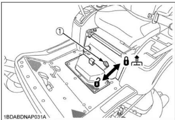
(1) Lift lock lever: "LOCK"
i
a: "UNLOCK"
OPERATING THE MOWER
MAKING THE MOST OF YOUR MOWER
- When using your mower for the first time, choose a smooth level area and cut in straight and slightly overlapping strips.
- The size and type of the area to be mowed will determine the proper mowing pattern. Take into account obstructions, such as trees, fences and buildings. To keep grass clippings off fences, sidewalks, etc., it is advisable to go over the outside of the area to be mowed several times in a clockwise direction. To mow the area remaining, work in a counterclockwise direction so that the clippings are dispersed onto the previously cut area.
- Always keep the left side of the mower toward trees, posts or other obstacles on the first trip around the obstacle.
- Most lawns should be mowed to keep the grass approximately 50 to 80 mm (2 to 3 in.) high. Best results are obtained by cutting often and not too short. To keep a green lawn, never mow more than 1/3 of the height of the grass or a maximum of 25 mm (1 in.) in 1 mowing.
For extremely tall grass, set the cutting height at maximum cutting height for the first mowing, then reset to the desired height and mow again. Allow the grass to grow to 80 mm (3 in.), then cut off only the top inch. - For best appearance, grass should be cut in the afternoon or evening when it is free of moisture.
ADJUSTING CUTTING HEIGHT

DANGER
To avoid serious injury or death:
- Do not engage the mower in the transport position.
- Before adjusting cutting height, check that all tire pressures are correct. If necessary adjust to the correct tire pressure.

(1) Lift lock lever : "LOCK"

: "UNLOCK"
- To set the cutting height, keep depressing the hydraulic lift control pedal firmly to raise mower deck to the top position. Make sure that the lift lock lever is in unlock position. Adjust the cutting height control dial to desired height.
- Use the higher settings for mowing in a rough area or when mowing tall grass. Lower settings should be used only for smooth lawns where short grass is desired.

(1) Cutting height control dial
(2) Hydraulic lift control pedal
- Lower the mower deck by releasing the hydraulic lift control pedal. This lowers the mower deck from the "TRANSPORT" position to the "OPERATING" position.
- Adjust the anti-scalp rollers' height as recommended below for normal operating condition. To minimize gouging and roller damage or wear, the anti-scalp rollers will maintain the ground clearance of 19 mm (3/4 in.).
IMPORTANT :
- Never allow roller to contact the ground continuously as premature roller wear may develop if set incorrectly.
- Anti-scalp rollers must maintain a minimum clearance of 6 mm (1/4 in.) to the ground.
[PIN]

1BDABCQAP136A
[BOLT]
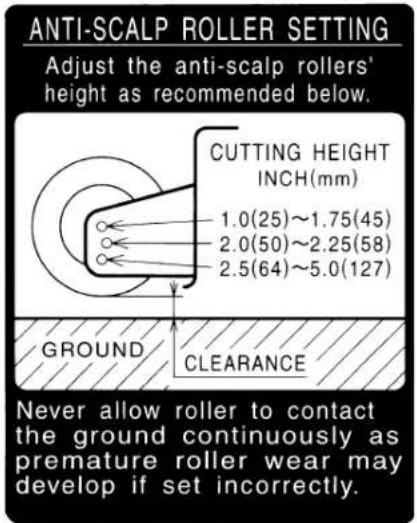
1BDABBSAP0130
![[RCK48P, RCK54P] ① ① ② ② 1BDABDNAP011B](/content/2026/06/1369073/images/9092814ad2a528324f40418da9cd1cf54eca5bf4869493d34525e06bf465fdab.jpg)
(1) Anti-scalp roller (Front, bolt shift type)
(2) Anti-scalp roller (Rear, bolt shift type)
[RCK48S]
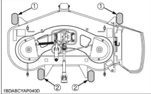
(1) Anti-scalp roller (Front, bolt shift type)
(2) Anti-scalp roller (Rear, bolt shift type)
![[RCK60P] ① ① ② ② 1BDABDMAP006C](/content/2026/06/1369073/images/88233af14bbcbf5ddd707a40051c24ed10686ca9660e1cfeeeb22b2ba61fff06.jpg)
(1) Anti-scalp roller (Front, pin shift type)
(2) Anti-scalp roller (Rear, bolt shift type)
Reference
- Set position for recommended ground clearance 19 mm (3/4 in.).
| Cutting height inch (mm) | Position of pins | Position of bolts | Ground clearance mm (Ref.) | |
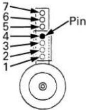 1BDABARAP131A 1BDABARAP131A |  1BDABCQAP162A 1BDABCQAP162A | |||
| Pin shift type | Bolt shift type | |||
| 1.00" (25) 1 | 1 | 6 | 6 | |
| 1.25" (32) 2 | 13 12 | |||
| 1.50" (38) 1 | 19 19 | |||
| 1.75" (44) 3 | 13 25 | |||
| 2.00" (50) 2 | 2 | 19 19 | ||
| 2.25" (58) 4 | 13 25 | |||
| 2.50" (64) 3 | 3 | 19 19 | ||
| 2.75" (70) 5 | 13 25 | |||
| 3.00" (76) 4 | 19 (31) *2 | |||
| 3.25" (83) 6 | 13 (38) *3 | |||
| 3.50" (89) 5 | 19 *1 (44) *3 | |||
| 3.75" (95) 7 | 13 *3 (51) *3 | |||
| 4.00" (102) | 6 19 *3 (57) *3 | |||
| 4.25" (108) | 7 13 *3 (63) *3 | |||
| 4.50" (114) | 7 19 *3 (70) *3 | |||
| 4.75" (121) | 7 25 *3 (76) *3 | |||
| 5.00" (127) | 7 31 *3 (83) *3 | |||
*1. For cutting heights above 3.5". The anti-scalp rollers will still be effective against scalping.
*2. For cutting heights above 3.0". The anti-scalp rollers will still be effective against scalping.
*3. Use it if necessary.
OPERATING MOWER

DANGER
To avoid serious injury or death:
- Do not operate the mower without the discharge deflector being in place properly.

CAUTION
To avoid personal injury:
- Clear the work area of objects which might be picked up and thrown.
- Do not direct the opening of the discharge chute at bystanders especially children or animals. Ejected objects may cause injury. Plan your mowing carefully before starting operations.
- Keep bystanders and animals away from the mowing area.
- Be sure to disengage the PTO clutch of the mower before attempting to start the engine.
■PTO Lever
To engage the PTO, move the PTO lever to the "ENGAGED" (ON) position.

(1) PTO lever "ENGAGED" (ON)
"DISENGAGED" (OFF)
- If you get off the seat while the PTO is running, the engine will stop automatically. (Operator presence control)
- Before starting the engine, pull the PTO lever to the "DISENGAGED" (OFF) position. If it is at the "ENGAGED" (ON) position, the engine will not start.
NOTE :
● These interlock features are built-in.
■ Starting

WARNING
To avoid serious injury or death:
- Engine components can get extremely hot from operation. To prevent severe burns, do not touch these areas while the engine is running, or immediately after it is turned off. Never operate the engine without heat shields or guards.
- Sit on the operator's seat.
- Start the engine.
- Engage the PTO lever.
- Disengage the parking brake.
- Speed up the engine by moving the throttle lever forward.
- Push or pull the motion control levers to move forward or backward.
IMPORTANT :
- Never attempt to move the machine with the parking brake "ON".
NOTE :
- Keep the engine running at full throttle for best results. Control the travel speed with the motion control levers.
● During heavy duty use, operate the machine at a slower ground speed or go over the area twice. - Keep the mower deck in the raised position when the mower is disengaged.
- The mower will not cut cleanly if the ground speed is too high or if the blade speed drops due to an overload.
- If debris builds up on the grass screen or other cooling air intake areas, stop the engine and clean them. Operating the engine with blocked or dirty air intake and cooling areas causes damage due to overheating.
TIRES AND WHEELS
TIRES

WARNING
To avoid serious injury or death:
- Do not attempt to mount a tire. This should be done by a qualified person with the proper equipment.
● Always maintain the correct tire pressure. Do not inflate tires above the recommended pressure shown in the Operator's Manual.
● Inflation pressure in front tires rises quickly when using compressed air.

CAUTION
Never operate machine with a loose rim, wheel, or axle.
- Whenever bolts are loosened, retighten to specified torque.
- Check all bolts frequently and keep them tightened.
Inflation Pressure
Though the inflation pressure is factory-set to the prescribed level, it naturally drops slowly in the course of time. Thus, check it everyday and inflate as necessary.
| Tire sizes | Recommended Inflation Max. Pressure | |
| Front | 13 x 5.0 - 6,4PR Rib | 270 kPa(2.8 kgf/cm2, 40psi) |
| Rear | 23 x 10.5 - 12,4PR Turf | 140 kPa(1.4 kgf/cm2, 20psi) |

(1) Ground (A) "INSUFFICIENT"
(B) "NORMAL"
(C) "EXCESSIVE"
WHEELS
IMPORTANT :
- When re-fitting a wheel, tighten the wheel bolt to the following torques then recheck after traveling 200 m (200 yards) changing directions several times.

Wheels with beveled or tapered holes: Use the tapered wheel bolt.
■Remove and Install Front Caster Wheels
◆Removing
- Park the machine on a firm and level surface.
- Stop the engine and apply parking brake.
- Lift the front of machine with a safe lifting device.
- Remove the lock nut with nylon sleeve and the wheel bolt.
- Remove the wheel and dust cover from assembly yoke.
Installing
- Install the replacement wheel and dust cover.
- Install the wheel bolt and the lock nut with nylon sleeve.
- Tighten the nut.
- After installing, grease to the nipples.
IMPORTANT :
- Insert the wheel bolt from the outside of the yoke.
● Tighten the nut gradually until wheel bearing play is eliminated and wheel turns freely by hand.
Reference
| Tightening torque | 20 to 25 N-m(14.8 to 18.4 lbf-ft)(2 to 2.5 kgf-m) |
- Lower machine.

(1) Lock nut
(2) Wheel bolt
(3) Yoke
(4) Dust cover
MAINTENANCE
SERVICE INTERVALS
The following servicing tasks should be carried out on the machine at the stated running-time intervals.
| No. Items | Indication hour meter (Hr) | Ref.Page | ||||||||||||||||
| 50 1 | 100 150 | 200 | 250 30 | 30 350 | 400 450 | 500 | 550 600 | After since | ||||||||||
| 1 Engine oil Change every 100Hr 52 *1 | ◎ | ○ | ○ | ○ | ○ | ○ | ||||||||||||
| 2 Engine oil filter Replace every 200Hr 64 *1 | ◎ | ○ | ○ | |||||||||||||||
| 3 Transmission oil filter Replace every 200Hr 65 *1 | ○ | ○ | ○ | |||||||||||||||
| 4 Mower gear box oil | Check every 50Hr | ○ | 49○ | ○ | ○ | ○ | ○ | ○ | ○ | ○ | ○ | ○ | ○ | |||||
| Change | ○ | ○ | ○ | ○ | every 150Hr 62 | |||||||||||||
| 5 | Engine start system | Check | ○ | ○ | ○ | ○ | ○ | ○ | ○ | ○ | ○ | ○ | ○ | ○ | every 50Hr | 47 | ||
| 6 OPC system Check every 50Hf | 48 | ○ | ○ | ○ | ○ | ○ | ○ | ○ | ○ | ○ | ○ | ○ | ||||||
| 7 | Greasing (except mower) | - | ○ | ○ | ○ | ○ | ○ | ○ | ○ | ○ | ○ | ○ | ○ | ○ | every 50Hr | 50 | ||
| 8 | Oiling | - | ○ | ○ | ○ | ○ | ○ | ○ | ○ | ○ | ○ | ○ | ○ | ○ | every 50Hr | 52 | ||
| 9 | Air cleaner primary element | Clean | ○ | ○ | ○ | ○ | ○ | ○ | every 100Hr 53 *2 | |||||||||
| Replace | every 1000Hror 1 year | 68 *3 | ||||||||||||||||
| Secondary element | Replace | every 1000Hror 1 year | 68 *3 | |||||||||||||||
| 10 | Carbon canister air filter | Check | ○ | ○ | ○ | ○ | ○ | ○ | every 100Hr 62 | *9 | ||||||||
| Replace | every 2 years 70 | |||||||||||||||||
| 11 | Fuel filter element | Check | ○ | ○ | ○ | ○ | ○ | ○ | every 100Hr 56 | |||||||||
| Replace every 400Hr 68 *6 | ○ | |||||||||||||||||
| 12 | Parking brake | Adjust | ○ | ○ | ○ | ○ | ○ | ○ | every 100Hr | 58 | *9 | |||||||
| 13 | Battery condition | Check | ○ | ○ | ○ | ○ | ○ | ○ | every 100Hr | 60 | *7 | |||||||
| 14 | Engine shroud panel | Clean | ○ | ○ | ○ | ○ | ○ | ○ | every 100Hr | 53 | *9 | |||||||
| 15 | Engine oil cooler fins[ZG227 only] | Clean | ○ | ○ | ○ | ○ | ○ | ○ | every 100Hr 55 | *8*9 | ||||||||
| 16 | Fuel filter bowl | Clean | ○ | ○ | ○ | ○ | ○ | ○ | every 100Hr | 57 | ||||||||
| 17 | Throttle cable | Adjust | ○ | ○ | ○ | ○ | ○ | ○ | every 100Hr | 61 | ||||||||
| 18 | Spark plug condition and gap | Check | ○ | ○ | ○ | every 200Hr 64 | ||||||||||||
| 19 | Motion control lever pivot | Adjust | ○ | ○ | ○ | every 200Hr | 66 | |||||||||||
| 20 | Engine shroud | Clean | ○ | ○ | ○ | every 200Hr | 66 | *6 | ||||||||||
| 21 | Transmission strainer | Clean | ◎ | every 400Hr | 68 | |||||||||||||
| 22 | Transmission fluid and Rear axle gear case(RH & LH) fluid | Change | ◎ | every 400Hr 66 | ||||||||||||||
| 23 | Engine valve clearance | Adjust | ○ | every 500Hr | 68 | |||||||||||||
| 24 | Combustion chamber | Clean | *5 | 68 | ||||||||||||||
| 25 | Fuel line | Check | every 1 year | 69 | *4*9 | |||||||||||||
| Replace | every 4 years 70 *6 | |||||||||||||||||
| No. | Items | Indication hour meter (Hr) | Ref.Page | ||||||||||||||
| 50 | 100 | 150 | 200 | 250 | 300 | 350 | 400 | 450 | 500 | 550 | 600 | After since | |||||
| 26 Hydraulic hose | Check every 1 year 69 | *4*9 | |||||||||||||||
| Replace every 4 years 70 *6 | |||||||||||||||||
| 27 Intake air line | Check every 1 year 69 | *4*9 | |||||||||||||||
| Replace every 4 years 70 *9 | |||||||||||||||||
| 28 Engine breather hose | Check every 1 year 70 | *4*6 | |||||||||||||||
| Replace every 4 years 70 *6 | |||||||||||||||||
| 29 Mower gear box oil seal | Check every 1 year 70 | *4*6 | |||||||||||||||
| Replace every 4 years 70 *6 | |||||||||||||||||
| 30 Fuse Replace | Service as required | 70 | |||||||||||||||
| 31 Blade Replace 71 | |||||||||||||||||
| 32 Mower belt Replace 73 | |||||||||||||||||
| 33 Fuel system Bleed | 73 | ||||||||||||||||
IMPORTANT :
● The jobs indicated by must be done initially.
*1 The initial 50 hours should not be a replacement (change) cycle.
*2 Air cleaner must be cleaned more often in dusty conditions than in normal conditions.
*3 Every 1000 hours or every 1 year whichever comes faster.
*4 Replace if any deterioration (crack, hardening, scar, or deformation) or damage occurred.
*5 On every after 1000 Hr, clean it if necessary.
*6 Consult your local KUBOTA Dealer for this service.
*7 When the battery is used for less than 100 hours per year, check the battery condition by reading the indicator annually.
*8 This maintenance should be done daily or more often in dusty condition than in normal conditions.
Suggested cleaning interval is every 100 hours in normal conditions.
*9 If you feel you are unable to make the following service correctly and safely, contact your local KUBOTA Dealer.
● GASOLINE ENGINE EMISSION RELATED MAINTENANCE INSTRUCTIONS:
- Non-warranty maintenance, repair, or replacement of the emission control devices and systems should be performed by a qualified repair establishment or individual which has the experience and equipment to perform such work.
See the Emissions Warranty Statement.
- To ensure the best quality and reliability, use new KUBOTA Genuine parts or their equivalents for repair and replacement, whenever you have maintenance done.
PERIODIC SERVICE CHART LABEL
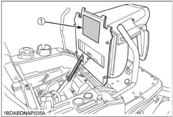

(1) Part No. K3272-6551-6 (ENGLISH) (2) Part No. K3272-6552-6 (SPANISH)
| PERIODIC SERVICE CHART | |||||
| INTERNAL | RECOMMENDED SERVICE ※ | INTERNAL | RECOMMENDED SERVICE ※ | ||
| DAILY | CHECK 1. I'm pressure, wear or damage. 2. Fuel oil or outage from machines and motors. 3. Engine and transmission oil and fuel level. 4. Damage to machine body, lightness of all of units, nuts and pins, etc. 5. Mower blades and belt for wear or damage. 6. Parking trains, speed controlvers, all safety switches and easy checker functions. 7. Color of the exhaust fumes, abnormal noise and vibrations. 8. AC# air 9. Rear switch, air cleaner primary element, mower deck or rear door dust cover. Engine cooling area. OR#ASE Mower U-ped (5 pieces) Spindle shaft (3 pieces) Wheel tension (mil/s) (pens) Wheel tension post (1 piece) OR#ASE 100 Hr OR#ASE 150 Hr OR#ASE 200 Hr OR#ASE 250 Hr OR#ASE 300 Hr OR#ASE 400 Hr OR#ASE 500 Hr OR#ASE 600 Hr OR#ASE 700 Hr OR#ASE 800 Hr OR#ASE 900 Hr OR#ASE 1000 Hr OR#ASE 1100 Hr OR#ASE 1200 Hr OR#ASE 1300 Hr OR#ASE 1400 Hr OR#ASE 1500 Hr OR#ASE 1600 Hr OR#ASE 1700 Hr OR#ASE 1800 Hr OR#ASE 1900 Hr OR#ASE 2000 Hr OR#ASE 2100 Hr OR#ASE 2200 Hr OR#ASE 2300 Hr OR#ASE 2400 Hr OR#ASE 2500 Hr OR#ASE 2600 Hr OR#ASE 2700 Hr OR#ASE 2800 Hr OR#ASE 2900 Hr OR#ASE 3000 Hr OR#ASE 3100 Hr OR#ASE 3200 Hr OR#ASE 3300 Hr OR#ASE 3400 Hr OR#ASE 3500 Hr OR#ASE 3600 Hr OR#ASE 3700 Hr OR#ASE 3800 Hr OR#ASE 3900 Hr OR#ASE 4000 Hr OR#ASE 4100 Hr OR#ASE 4200 Hr OR#ASE 4300 Hr OR#ASE 4400 Hr OR#ASE 4500 Hr OR#ASE 4600 Hr OR#ASE 4700 Hr OR#ASE 4800 Hr OR#ASE 4900 Hr OR#ASE 5000 Hr OR#ASE 5100 Hr OR#ASE 5200 Hr OR#ASE 5300 Hr OR#ASE 5400 Hr OR#ASE 5500 Hr OR#ASE 5600 Hr OR#ASE 5700 Hr OR#ASE 5800 Hr OR#ASE 5900 Hr OR#ASE 6000 Hr OR#ASE 6100 Hr OR#ASE 6200 Hr OR#ASE 6300 Hr OR#ASE 6400 Hr OR#ASE 6500 Hr OR#ASE 6600 Hr OR#ASE 6700 Hr OR#ASE 6800 Hr OR#ASE 6900 Hr OR#ASE 7000 Hr OR#ASE 7100 Hr OR#ASE 7200 Hr OR#ASE 7300 Hr OR#ASE 7400 Hr OR#ASE 7500 Hr OR#ASE 7600 Hr OR#ASE 7700 Hr OR#ASE 7800 Hr OR#ASE 7900 Hr OR#ASE 8000 Hr OR#ASE 8100 Hr OR#ASE 8200 Hr OR#ASE 8300 Hr OR#ASE 8400 Hr OR#ASE 8500 Hr OR#ASE 8600 Hr OR#ASE 8700 Hr OR#ASE 8800 Hr OR#ASE 8900 Hr OR#ASE 9000 Hr OR#ASE 9100 Hr OR#ASE 9200 Hr OR#ASE 9300 Hr OR#ASE 9400 Hr OR#ASE 9500 Hr OR#ASE 9600 Hr OR#ASE 9700 Hr OR#ASE 9800 Hr OR#ASE 9900 Hr OR#ASE 10000 Hr OR#ASE 10100 Hr OR#ASE 10200 Hr OR#ASE 10300 Hr OR#ASE 10400 Hr OR#ASE 10500 Hr OR#ASE 10600 Hr OR#ASE 10700 Hr OR#ASE 10800 Hr OR#ASE 10900 Hr OR#ASE 11000 Hr OR#ASE 11100 Hr OR#ASE 11200 Hr OR#ASE 11300 Hr OR#ASE 11400 Hr OR#ASE 11500 Hr OR#ASE 11600 Hr OR#ASE 11700 Hr OR#ASE 11800 Hr OR#ASE 11900 Hr OR#ASE 12000 Hr OR#ASE 12100 Hr OR#ASE 12200 Hr OR#ASE 12300 Hr OR#ASE 12400 Hr OR#ASE 12500 Hr OR#ASE 12600 Hr OR#ASE 12700 Hr OR#ASE 12800 Hr OR#ASE 12900 Hr OR#ASE 13000 Hr OR#ASE 13100 Hr OR#ASE 13200 Hr OR#ASE 13300 Hr OR#ASE 13400 Hr OR#ASE 13500 Hr OR#ASE 13600 Hr OR#ASE 13700 Hr OR#ASE 13800 Hr OR#ASE 13900 Hr OR#ASE 14000 Hr OR#ASE 14100 Hr OR#ASE 14200 Hr OR#ASE 14300 Hr OR#ASE 14400 Hr OR#ASE 14500 Hr OR#ASE 14600 Hr OR#ASE 14700 Hr OR#ASE 14800 Hr OR#ASE 14900 Hr OR#ASE 15000 Hr OR#ASE 15100 Hr OR#ASE 15200 Hr OR#ASE 15300 Hr OR#ASE 15400 Hr OR#ASE 15500 Hr OR#ASE 15600 Hr OR#ASE 15700 Hr OR#ASE 15800 Hr OR#ASE 15900 Hr OR#ASE 16000 Hr OR#ASE 16100 Hr OR#ASE 16200 Hr OR#ASE 16300 Hr OR#ASE 16400 Hr OR#ASE 16500 Hr OR#ASE 16600 Hr OR#ASE 16700 Hr OR#ASE 16800 Hr OR#ASE 16900 Hr OR#ASE 17000 Hr OR#ASE 17100 Hr OR#ASE 17200 Hr OR#ASE 17300 Hr OR#ASE 17400 Hr OR#ASE 17500 Hr OR#ASE 17600 Hr OR#ASE 17700 Hr OR#ASE 17800 Hr OR#ASE 17900 Hr OR#ASE 18000 Hr OR#ASE 18100 Hr OR#ASE 18200 Hr OR#ASE 18300 Hr OR#ASE 18400 Hr OR#ASE 18500 Hr OR#ASE 18600 Hr OR#ASE 18700 Hr OR#ASE 18800 Hr OR#ASE 18900 Hr OR#ASE 19000 Hr OR#ASE 19100 Hr OR#ASE 19200 Hr OR#ASE 19300 Hr OR#ASE 19400 Hr OR#ASE 19500 Hr OR#ASE 19600 Hr OR#ASE 19700 Hr OR#ASE 19800 Hr OR#ASE 19900 Hr OR#ASE 20000 Hr OR#ASE 20100 Hr OR#ASE 20200 Hr OR#ASE 20300 Hr OR#ASE 20400 Hr OR#ASE 20500 Hr OR#ASE 20600 Hr OR#ASE 20700 Hr OR#ASE 20800 Hr OR#ASE 20900 Hr OR#ASE 21000 Hr OR#ASE 21100 Hr OR#ASE 21200 Hr OR#ASE 21300 Hr OR#ASE 21400 Hr OR#ASE 21500 Hr OR#ASE 21600 Hr OR#ASE 21700 Hr OR#ASE 21800 Hr OR#ASE 21900 Hr OR#ASE 22000 Hr OR#ASE 22100 Hr OR#ASE 22200 Hr OR#ASE 22300 Hr OR#ASE 22400 Hr OR#ASE 22500 Hr OR#ASE 22600 Hr OR#ASE 22700 Hr OR#ASE 22800 Hr OR#ASE 22900 Hr OR#ASE 23000 Hr OR#ASE 23100 Hr OR#ASE 23200 Hr OR#ASE 23300 Hr OR#ASE 23400 Hr OR#ASE 23500 Hr OR#ASE 23600 Hr OR#ASE 23700 Hr OR#ASE 23800 Hr OR#ASE 23900 Hr OR#ASE 24000 Hr OR#ASE 24100 Hr OR#ASE 24200 Hr OR#ASE 24300 Hr OR#ASE 24400 Hr OR#ASE 24500 Hr OR#ASE 24600 Hr OR#ASE 24700 Hr OR#ASE 24800 Hr OR#ASE 24900 Hr OR#ASE 25000 Hr OR#ASE 25100 Hr OR#ASE 25200 Hr OR#ASE 25300 Hr OR#ASE 25400 Hr OR#ASE 25500 Hr OR#ASE 25600 Hr OR#ASE 25700 Hr OR#ASE 25800 Hr OR#ASE 25900 Hr OR#ASE 26000 Hr OR#ASE 26100 Hr OR#ASE 26200 Hr OR#ASE 26300 Hr OR#ASE 26400 Hr OR#ASE 26500 Hr OR#ASE 26600 Hr OR#ASE 26700 Hr OR#ASE 26800 Hr OR#ASE 26900 Hr OR#ASE 27000 Hr OR#ASE 27100 Hr OR#ASE 27200 Hr OR#ASE 27300 Hr OR#ASE 27400 Hr OR#ASE 27500 Hr OR#ASE 27600 Hr OR#ASE 27700 Hr OR#ASE 27800 Hr OR#ASE 27900 Hr OR#ASE 28000 Hr OR#ASE 28100 Hr OR#ASE 28200 Hr OR#ASE 28300 Hr OR#ASE 28400 Hr OR#ASE 28500 Hr OR#ASE 28600 Hr OR#ASE 28700 Hr OR#ASE 28800 Hr OR#ASE 28900 Hr OR#ASE 29000 Hr OR#ASE 29100 Hr OR#ASE 29200 Hr OR#ASE 29300 Hr OR#ASE 29400 Hr OR#ASE 29500 Hr OR#ASE 29600 Hr OR#ASE 29700 Hr OR#ASE 29800 Hr OR#ASE 29900 Hr OR#ASE 30000 Hr OR#ASE 30100 Hr OR#ASE 30200 Hr OR#ASE 30300 Hr OR#ASE 30400 Hr OR#ASE 30500 Hr OR#ASE 30600 Hr OR#ASE 30700 Hr OR#ASE 30800 Hr OR#ASE 30900 Hr OR#ASE 31000 Hr OR#ASE 31100 Hr OR#ASE 31200 Hr OR#ASE 31300 Hr OR#ASE 31400 Hr OR#ASE 31500 Hr OR#ASE 31600 Hr OR#ASE 31700 Hr OR#ASE 31800 Hr OR#ASE 31900 Hr OR#ASE 32000 Hr OR#ASE 32100 Hr OR#ASE 32200 Hr OR#ASE 32300 Hr OR#ASE 32400 Hr OR#ASE 32500 Hr OR#ASE 32600 Hr OR#ASE 32700 Hr OR#ASE 32800 Hr OR#ASE 32900 Hr OR#ASE 33000 Hr OR#ASE 33100 Hr OR#ASE 33200 Hr OR#ASE 33300 Hr OR#ASE 33400 Hr OR#ASE 33500 Hr OR#ASE 33600 Hr OR#ASE 33700 Hr OR#ASE 33800 Hr OR#ASE 33900 Hr OR#ASE 34000 Hr OR#ASE 34100 Hr OR#ASE 34200 Hr OR#ASE 34300 Hr OR#ASE 34400 Hr OR#ASE 34500 Hr OR#ASE 34600 Hr OR#ASE 34700 Hr OR#ASE 34800 Hr OR#ASE 34900 Hr OR#ASE 35000 Hr OR#ASE 35100 Hr OR#ASE 35200 Hr OR#ASE 35300 Hr OR#ASE 35400 Hr OR#ASE 35500 Hr OR#ASE 35600 Hr OR#ASE 35700 Hr OR#ASE 35800 Hr OR#ASE 35900 Hr OR#ASE 36000 Hr OR#ASE 36100 Hr OR#ASE 36200 Hr OR#ASE 36300 Hr OR#ASE 36400 Hr OR#ASE 36500 Hr OR#ASE 36600 Hr OR#ASE 36700 Hr OR#ASE 36800 Hr OR#ASE 36900 Hr OR#ASE 37000 Hr OR#ASE 37100 Hr OR#ASE 37200 Hr OR#ASE 37300 Hr OR#ASE 37400 Hr OR#ASE 37500 Hr OR#ASE 37600 Hr OR#ASE 37700 Hr OR#ASE 37800 Hr OR#ASE 37900 Hr OR#ASE 38000 Hr OR#ASE 38100 Hr OR#ASE 38200 Hr OR#ASE 38300 Hr OR#ASE 38400 Hr OR#ASE 38500 Hr OR#ASE 38600 Hr OR#ASE 38700 Hr OR#ASE 38800 Hr OR#ASE 38900 Hr OR#ASE 39000 Hr OR#ASE 39100 Hr OR#ASE 39200 Hr OR#ASE 39300 Hr OR#ASE 39400 Hr OR#ASE 39500 Hr OR#ASE 39600 Hr OR#ASE 39700 Hr OR#ASE 39800 Hr OR#ASE 39900 Hr OR#ASE 40000 Hr | ||||
1BDABDNAP079A
| Place | Capacities | Lubricants | |||
| ZG222SA ZG | 222A ZG227A, | ZG227LA | |||
| Fuel 27 L (7.1 U.S. gals.) | Automobile unleaded or regular gasolineUnleaded gasoline 87 octane or higher | ||||
| Engine crankcase 1.8 | L (1.9 U.S.qts.)*1 | 2.0 L (2.1 U.S. | qts.)*1 | Engine oil: API serviceClassification SG, SH, SJ or higherAbove -18(1)....FAE10W-30 or 10W-40Below 0(32)...FAE5W-20 or 5W-30 | |
| Transmission case with filter & hoseRear axle gear case (RH &LH) | 7.5 L (7.9 U.S.qts.) KUBOTA SUPER UDT | 2 fluid*2 | |||
| Mower gear box | 0.15 L(0.16 U.S.qts.) | -KUBOTA SUPER UDT | fluid*2 | ||
| -0.4 L (0.42 U.S.qts.) | SAE90 gear oil(API service classification: more than GL-3) | ||||
| Greasing No. of greasing points Capacity Type of grease | |||||
| Front axle 2 | Until grease | overflows | Multipurpose EP2 Grease(NLGI Grade No.2) | ||
| Front wheel | 2 | ||||
| Front lift arm | 2 | ||||
| Parking brake lock pedal | 1 | ||||
| Motion control lever pivot bushing, and contact position | 6 | ||||
| Universal joint | 1 | ||||
| Seat adjuster | 2 | ||||
| Cable (throttle cable,mower lift cable,choke cable) | 5 | Moderate amount | Oil | ||
| [MOWER] | Until grease overflows | Multipurpose EP2 Grease(NLGI Grade No.2) | |||
| Universal joint | 3 | ||||
| Three spindle shafts | 3 | ||||
| Belt tension pulley | 1 | ||||
| Belt tension pivot | 1 | ||||
| Anti scalp roller | 4 | ||||
Note *1 Oil amount when the oil level is at the upper level of the oil level gauge.
*2 The product name of KUBOTA genuine UDT fluid may be different from that in the Operator's Manual depending on countries or territories. Consult your local KUBOTA Dealer for further detail.
IMPORTANT :
- To prevent serious damage to hydraulic systems, use only KUBOTA genuine fluid or its equivalent.
NOTE :
◆Engine Oil:
- Oil used in the engine should have an American Petroleum Institute (API) service classification and proper SAE Engine Oil according to the ambient temperatures as shown above.
- Indicated capacity of oil is manufacture's estimate.
◆Transmission oil:
- KUBOTA Super UDT-2: For an enhanced ownership experience, we highly recommend Super UDT-2 to be used instead of standard hydraulic/transmission fluid.
Super UDT-2 is a proprietary KUBOTA formulation that deliveries superior performance and protection in all operating conditions.
Regular UDT is also permitted for use in this machine. - Indicated capacity of oil is manufacture's estimate.
◆Fuel:
- Gasohol (up to 10% ethyl alcohol, 90% unleaded gasoline by volume) is approved for the engine. Other gasoline/ alcohol blends are not approved.
- Indicated capacity of fuel is manufacture's estimate.
PERIODIC SERVICE
HOW TO OPEN THE HOOD AND STEP

CAUTION
To avoid personal injury from contact with moving parts:
● Never open the hood while the engine is running.
● Never open the step while the engine is running.
- Do not touch muffler or exhaust pipes while they are hot; Severe burns could result.
Hood
To open the hood, pull the lever sideward, and then open.

(1) Lever
(2) Hood
(A) "RELEASE"

(1) Hood
Step
To open the step, pull the grip.

(1) Step
(2) Grip
(A) "PULL"
HOW TO RAISE THE OPERATOR'S SEAT
◆Raise

CAUTION
To avoid personal injury:
● Fully raise the operator's seat. (To the locked position) Do not keep the seat halfway.
- Seat must be all the way back before raising.
- Pull the latch lever on the seat panel rearward.
● Fully raise the operator's seat. (To the locked position) Do not keep the seat halfway.
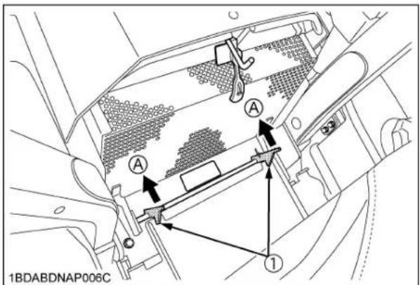
(1) Latch lever (A) "PULL"
- Raise the operator's seat to the "LOCK" position.
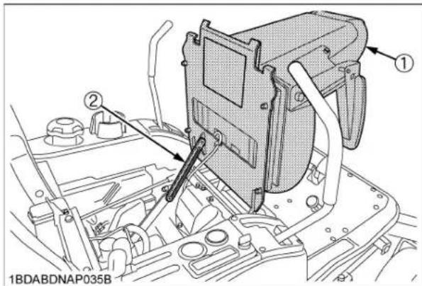
(1) Operator's seat
(2) Seat support rod
◆Lower

CAUTION
To avoid personal injury:
-
Do not drop the seat to close it.
● Watch your hands. Do not place your hands under the seat, when closing. -
Pull up the seat support rod and release the "LOCK".
- Lower the seat slowly to lock.
- Slide the seat to proper position.
HOW TO OPEN THE LEVER GUIDE

CAUTION
To avoid personal injury:
● Park the machine on a firm and level surface.
- Stop the engine, remove the key and apply the parking brake.
- Remove the four screws of the lever guide.
- Pull up the lever guide.
How to install the lever guide.
- Install the lever guide.
- Tighten the screws.
IMPORTANT :
- If the lever cover is out of alignment with the motion lever, move the lever cover to align it with the motion lever.

(1) Lever guide
(2) Screw
(3) Lever cover
LIFT-UP POINT

WARNING
To avoid serious injury, death or machine damage: ● Do not work under the machine unless it is secured by safe stands or suitable blocking.
■Front side:
Hook nylon slings at the front frame.
Hoist the front frame with the nylon sling or jack up the front frame.
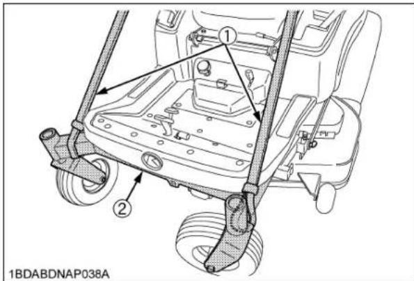
(1) Nylon sling
(2) Front frame
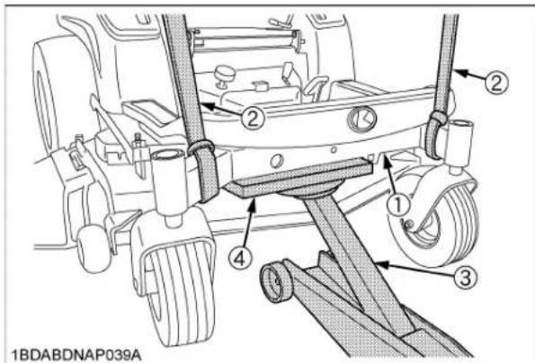
(1) Front frame
(2) Nylon sling
(3) Jack
(4) Wood block
■Rear side:
Hoist the rear frame with nylon slings. Or jack up the bottom plate.

(1) Rear frame
(2) Nylon sling
(3) Bottom plate
(4) Jack
DAILY CHECK
To prevent trouble from occurring, it is important to know the condition of the machine. Check it before starting.

CAUTION
To avoid personal injury:
- Be sure to check and service the machine on a level surface with the engine shut off, the key removed and the parking brake securely set or chock the rear wheels.
| No. | Check item | Ref.Page | |
| Walkingaround themachine | 1 | Damage of machine body, tightnessof all bolts, nuts and pins, etc. | - |
| 2 Fuel and oil leak - | |||
| 3 Tire pressure, wear and damage | 3245 | ||
| 4 Engine oil level 43 | |||
| 5 Fuel level 43 | |||
| 6 | Air intake screen, engine coolingarea | 44 | |
| 7 Transmission fluid level 46 | |||
| 8 Greasing 50 | |||
| 9 Brake play 58 | |||
| 10 Air cleaner primary element 53 | |||
| 11 Bottom dust cover 44 | |||
| 12 Machine body cleaning - | |||
| Mower | 1 Check all hardware. | - | |
| 2 Make sure all pins are in place | - | ||
| 3 Mower deck cleaning | - | ||
| 4 | GreasingUniversal jointThree spindle shaftsBelt tension pulleyBelt tension pivotAnti-scalp roller | 46 | |
| 5 Oil leak | 49 | ||
| 6 Make sure blade bolts are tight | 71 | ||
| 7 Blades and belt wear or damage | 71 | ||
| While sitting inthe operator'sseat | 1 Motion control lever | - | |
| 2 Parking brake | - | ||
| 3 Other movable parts | 47 | ||
| Turning thekey switch"ON" | 1 | Performance of the EasyChecker(TM) light | 14 |
| Starting the engine | 1 | Color of the exhaust fumes - | |
| 2 | Check for abnormal noise and vibration. | - | |
| 3 | Safety systems.If either of these do not operate properly, contact your local KUBOTA Dealer immediately. | 4748 | |
| Others | 1 | Check the areas where previous trouble was experienced. | - |
■ Checking Engine Oil Level

CAUTION
To avoid personal injury:
● Always stop the engine and remove the key before checking oil.
- Check engine oil before starting and 5 minutes or more after the engine has stopped.
- Wipe dipstick area clean.
- To check the oil level, remove the dipstick, wipe it clean, replace it, and draw it out again. Check to see that the oil level is between the 2 notches.
- Add new oil to the prescribed level at the oil port if necessary.

(1) Engine oil port
(2) Oil level dipstick
(A) "UPPER LEVEL"
(B) "LOWER LEVEL"
- When using a different brand or viscosity oil from the previous one, remove all of the old oil and oil filter. Never mix 2 different types of oil.
- Use the proper Engine Oil SAE according to the ambient temperatures. (See "LUBRICANTS AND FUEL" in "MAINTENANCE" section.)
■ Checking Amount of Fuel and Refueling

CAUTION
To avoid personal injury:
- Handle fuel carefully. If the engine is running, do not fill the fuel tank. If engine is hot, let engine cool several minutes before adding fuel. Do not smoke while filling the fuel tank or servicing the fuel system. Fill fuel tank only to bottom of filler neck. Do not fill completely full. The empty space in the tank allows gasoline to expand, when it heats up. Never remove the fuel tank cap or add fuel when the fuel tank is hot.

Check the fuel level. Take care that the fuel tank does not become empty.
Fuel tank capacity 27 L (7.1 U.S.gals.)
IMPORTANT :
- Do not mix oil with gasoline.
● Tighten the fuel cap until it clicks. - Do not use the fuel cap other than KUBOTA approved one.
- Do not permit dirt or trash or water to get into the fuel system.
- Be careful not to let the fuel tank become empty, otherwise air will enter the fuel system, necessitating bleeding before next engine start.
- Be careful not to spill fuel during refueling. If a spill should occur, wipe it off at once, or it may cause a fire.
Use only unleaded gasoline with an octane rating index of 87 or higher may be used.
NOTE :
- Use fuel within approximately 30 days after purchase to avoid deterioration in fuel quality, or add fuel stabilizer to keep fuel fresh and stabilized.
● Fuel blend differs from season to season for the best seasonal engine performance. To prevent engine performance troubles such as vapor lock or hard starting, use fuel within the season in which the fuel is purchased.
- Infrequent use of the engine during a season can make fuel stale in the fuel tank of the machine. Stale fuel condition can cause engine performance troubles by varnish and plugged carburetor components.
- Seal the fuel storage container tightly and store it out of sunlight and heat to prevent fuel degradation.
- Condensation in the fuel tank may occur because of various operating or environmental conditions. To reduce condensation and avoid affecting machine operation, fill the fuel tank at the end of daily operations.
IMPORTANT :
- Do not use old fuel.
[Use of alcohol mixed gasoline (Gasohol)]
Use "gasohol" only when the ethanol additive is less than 10% of the fuel. The use of methanol additive is not recommended. For the best results, use unleaded fuel with a minimum of 87 octane.

(1) Fuel tank cap
(C) Clearance
(2) Fuel tank filler neck
(Fuel level is under the filler neck.)
(3) Empty space
(4) Max. fuel level
■ Checking and Cleaning Air Intake Screen and Air Intake Area to Prevent Overheating

CAUTION
To avoid personal injury:
- Be sure to stop the engine and remove the key before cleaning.
IMPORTANT :
● The air intake screen and air intake area must be clear of debris to prevent the engine from overheating.
Daily or after every 5 hours of operation, check to be sure the air intake screen and the air intake area are clean.
Dirt or chaff around the air intake screen and air intake area or the engine cooling area decrease cooling performance.
- Open the hood and remove all foreign material.
- Remove the dust and all foreign material from the intake screen.
- Undo the rubber hook and open the air intake screen.

(1) Air intake screen
(A) "OPEN"
(2) Rubber hook
- Remove the dust and all foreign materials from the air intake area between the transmission and the engine dust plate.
- Each time the dust cover is covered with grass and foreign materials during operation, rub it off the dust cover with hand. Check the air intake area from time to time if grass accumulates.

(1) Air intake screen
(A) "PUSH DOWN"
(2) Engine dust plate
(B) Bracket
(3) Dust cover
(4) Bottom clean lever
- If the dust or chaff has accumulated air intake area, clean them completely by pushing down the bottom clean lever several times.
When using the bottom clean lever, remove the lever from the bracket.
After cleaning, make sure that the lever is replaced in place.
■ Checking Tire Pressure

WARNING
To avoid serious injury or death:
- Do not attempt to mount a tire on a rim. This should be done by a qualified person with the proper equipment.
● Always maintain the correct tire pressure. Inflation pressure in front tires rises quickly when using compressed air.
Do not inflate tires above the recommended pressure shown in the Operator's Manual.
IMPORTANT :
- Do not use tires larger than specified.
Inflation Pressure
Though the inflation pressure is factory-set to the prescribed level, it naturally drops slowly in the course of time. Thus, check it and inflate as necessary.
| Tire sizes | Recommended Inflation Max. Pressure | |
| Front | 13 x 5.0 - 6,4PR Rib | 270 kPa(2.8 kgf/cm2, 40 psi) |
| Rear | 23 x 10.5 - 12,4PR Turf | 140 kPa(1.4 kgf/cm2, 20 psi) |

(1) Ground (A) "INSUFFICIENT"
(B) "NORMAL"
(C) "EXCESSIVE"
■Checking Transmission Fluid Level

CAUTION
To avoid personal injury:
- Allow the transmission case to cool down sufficiently when cleaning its surface.
- Park the machine on a flat surface, lower the implement to the ground and shut off the engine and remove the key.
Allow the machine to idle for 1-3 minutes, and then check fluid. - Raise and lock the operator's seat.
- To check the oil level, draw out the dipstick, wipe it clean, replace it, and draw it out again. Check to see that the oil level lies between the two notches.
If the level is too low, add the new oil to the prescribed level at the oil inlet.
(See "LUBRICANTS AND FUEL" in "MAINTENANCE" section.)

(1) Oil level dipstick
(A) Oil level is acceptable
(2) Oil plug and breather cup
within this range.
IMPORTANT :
- If oil level is low, do not run engine. Add the new oil to the prescribed level at the oil inlet.
■Lubricating All Grease Fittings

CAUTION
To avoid personal injury:
- Be sure to stop the engine and remove the key before greasing.
Grease the following location.

(1) Mower universal joint
![[RCK48S] 1BDABDMAP008A](/content/2026/06/1369073/images/8a4a242f3412bbae5d5404e6f512014f8ca955f0ba3fd7c79fa03d3211105ad7.jpg)
![[RCK48P, RCK54P] ① ④ ② ③ ④ ④ ④ DO NOT REMOVE 1BDABDNAP043A](/content/2026/06/1369073/images/0ae41690779ef7feeb49343900ab024718c5712e7e1025579799eb10f5bfb443.jpg)
![[RCK60P] 1BDABDMAP009A](/content/2026/06/1369073/images/1f34bf9992fe424dc6951f9c1c1f66cb1fc6221384b6fa57468e76bb61b87955.jpg)
(1) Spindle shaft
(2) Belt tension pulley
(3) Belt tension pivot
(4) Anti-scalp roller (Grease the bosses.)
■ Checking Movable Parts
If any of the movable parts, such as levers and pedals, is not smoothly moved because of rust or anything sticky, do not attempt to force it into motion.
In the above case, remove the rust or the sticky thing, and apply oil or grease on the relevant spot.
Otherwise, the machine may get damaged.
EVERY 50 HOURS
■ Checking Engine Start System
The Engine Start System in your machine is designed to protect you while operating. Check the Engine Start System periodically. It is recommended to check the Engine Start System before daily operation.

WARNING
To avoid serious injury or death:
- Do not allow anyone near the machine while testing.
- If the machine does not pass one of the following tests, do not operate the machine. See your local KUBOTA Dealer.
- Sit on operator's seat for all tests except for Test 1.
IMPORTANT :
- Check the following tests before operating the machine.

(1) Parking brake lock pedal
(2) Motion control lever
(3) Key switch
(4) PTO lever
(5) Seat switch
Test 1 (OPERATOR NOT ON THE SEAT)
- Securely set the parking brake.
- Shift the PTO lever to "DISENGAGE" (OFF) position.
- Set the motion control levers to the "NEUTRAL LOCK" position.
- Turn the key switch to "START" position.
- The engine must not crank.
Test 2 (OPERATOR ON THE SEAT)
- Do not set the parking brake. (release it from test 1)
- Shift the PTO lever to "DISENGAGE" (OFF) position.
- Set the motion control levers to the "NEUTRAL LOCK" position.
- Turn the key switch to "START" position.
- The engine must not crank.
Test 3 (OPERATOR ON THE SEAT)
- Securely set the parking brake.
- Shift the PTO lever to "DISENGAGE" (OFF) position.
- Hold the motion control levers and move then inward from "NEUTRAL LOCK" position to "NEUTRAL" position and then release the levers.
- Turn the key switch to "START" position.
- The engine must not crank.
Test 4 (OPERATOR ON THE SEAT)
- Securely set the parking brake.
- Shift the PTO lever to "ENGAGE" (ON) position.
- Set the motion control levers to the "NEUTRAL LOCK" position.
- Turn the key switch to "START" position.
- The engine must not crank.
NOTE :
- If the engine cranks Test 1 through 4, consult your local KUBOTA Dealer to have the unit checked before operation.
Test 5 (OPERATOR ON THE SEAT)
- Start the engine.
- Keep the parking brake securely set.
- Shift the PTO lever to "DISENGAGE" (OFF) position.
- Hold the motion control levers and move then inward from "NEUTRAL LOCK" position to "NEUTRAL" position and then release the levers.
- The engine must shut off after a short time delay.
IMPORTANT :
- For this test only, the engine will shut off in a few seconds.
NOTE :
- If the engine remains running in Test 5, consult your local KUBOTA Dealer to have the unit checked before operation.
■ Checking OPC System
The OPC (Operator Presence Control) system in your machine is designed to protect you while operating. Check the OPC system periodically. It is recommended to check the OPC system before daily operation.

WARNING
To avoid serious injury or death:
- Do not allow anyone near the machine while testing.
- If the machine does not pass one of the following tests, do not operate the machine. See your local KUBOTA Dealer.

(1) Parking brake lock pedal
(2) Motion control lever
(3) Key switch
(4) PTO lever
(5) Seat switch
Test 1 (OPERATOR ON THE SEAT)
- Start the engine.
- Do not set the parking brake.
- Shift the PTO lever to "DISENGAGE" (OFF) position.
- Hold the motion control levers and move them inward from "NEUTRAL LOCK" position to "NEUTRAL" position and then release the levers.
- Stand up. (Do not get off the machine.)
- The engine must shut off.
Test 2 (OPERATOR ON THE SEAT)
- Start the engine.
- Do not set the parking brake.
- Shift the PTO lever to "ENGAGE" (ON) position.
- Stand up. (Do not get off the machine.)
- The engine must shut off.
NOTE :
- If the engine remains running in Test 1 or 2, consult your local KUBOTA Dealer to have the unit checked before operation.
■ Checking Gear Box Oil Level

CAUTION
To avoid personal injury:
● Always stop the engine and remove the key before checking oil.
If serial numbers of mower are as indicated below
RCK48S-222Z:all
RCK48P-222Z:30000 and below
RCK54P-227Z:30000 and below
RCK60P-227Z:30000 and below
- Park the machine on a flat surface and lower the mower to the ground.
To check the oil level, loosen the check plug and check to see if the oil level is in the range of the check plug port.
If the level is too low, add new oil to the prescribed level at the oil inlet.
(See "LUBRICANTS AND FUEL" in "MAINTENANCE" section.)
- After checking, reinstall the check plug and oil inlet plug securely.
![[RCK48S] ① ② 1BDABBSAP106B](/content/2026/06/1369073/images/38f1ae621bc0ed38d77d1d982a4cb8baf557356b27483cef1c9fbef0ad4ebf4c.jpg)
(1) Check plug
(2) Oil inlet plug
![[RCK48P, RCK54P, RCK60P] ③ ④ ② ① 1BDABCVAP057C](/content/2026/06/1369073/images/820700fcedf18fee33954e144d04568629444b990036061e320538fc4f1a2887.jpg)

(1) Drain plug
(2) Check plug
(3) Oil inlet plug
(4) Gear case
(5) Check plug port
(A) Oil level is acceptable within this range.
(B) Oil level
If serial numbers of mower are as indicated below RCK48P-222Z:30001 and above RCK54P-227Z:30001 and above RCK60P-227Z:30001 and above
- Park the machine on a flat surface and lower the mower to the ground.
To check the oil level, loosen the oil inlet plug with gauge, wipe it clean, reinstall it and loosen it again.
Check to see if the oil level is between the notch and tip.
If the level is too low, add new oil to the prescribed level at the oil inlet.
(See "LUBRICANTS AND FUEL" in "MAINTENANCE" section.)
- After checking, reinstall the oil inlet plug with gauge securely.
![[RCK48P, RCK54P, RCK60P] ① ② ③ ④ 1BDABDRAP034D](/content/2026/06/1369073/images/5e97f109ae5aa583f00f96dc6388fe259c170f875e8f92314fa169aad7fd8d21.jpg)
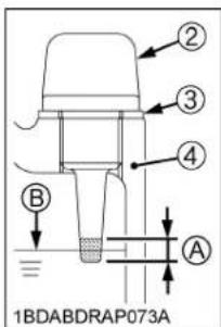
(1) Drain plug
(2) Oil inlet plug with gauge
(3) Seal washer
(4) Gear case
(A) Oil level is acceptable within this range.
(B) Oil level
Greasing

CAUTION
To avoid personal injury:
- Be sure to stop the engine and remove the key before greasing.
Apply a small amount of multipurpose grease to the following points every 50 hours:
If you operated the machine in extremely wet and muddy conditions, lubricate grease fittings more often.
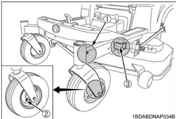
(1) Front axle (LH, RH)
(2) Front wheel (LH, RH)
(3) Front lift arm (LH, RH)

(1) Parking brake lock pedal
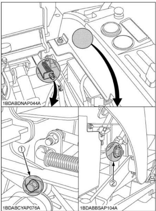
(1) Motion control lever pivot bushing (LH, RH) (2) Bushing

natural_image
Technical line drawing of a mechanical assembly with no visible text or symbols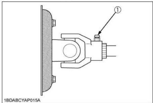
(1) Machine universal joint

(1) Motion control lever contact position (LH, RH)

(1) Seat adjuster
Oiling

natural_image
Technical line drawing of a mechanical assembly with no visible text or symbols(1) Lift control cable (oil)

(1) Choke cable (oil) (2) Throttle cable (oil)

(1) Choke cable (oil) (2) Throttle cable (oil)
EVERY 100 HOURS
■Changing Engine Oil

CAUTION
To avoid personal injury:
● Be sure to stop the engine and remove the key before changing the oil.
- Allow engine to cool down sufficiently; oil can be hot and may cause burns.
- To change the used oil, remove the drain plug at the bottom of the engine and drain the oil completely. The used oil can be drained out more easily if the engine is warm.

(1) Drain plug
- Fill with the new oil up to the upper level on the dipstick.

(1) Engine oil port
(2) Oil level dipstick
(A) "UPPER LEVEL" (B) "LOWER LEVEL"
- To check the oil level. Remove the dipstick, wipe it clean, insert it and draw it out again. Check to see that the oil level is between the two marks.
■Cleaning Air Cleaner Primary Element
-
Remove the air cleaner cover and primary element.
-
Clean the primary element:
(1) When dry dust adheres to the element, blow compressed air from the inside, turning the element. Pressure of compressed air must be under 205 kPa (2.1 kgf/cm², 30 psi).
(2) When carbon or oil adheres to the element, soak the element in detergent for 15 minutes then wash it several times in water, rinse with clean water and dry it naturally. After element is fully dried, inspect inside of the element with a light and check if it is damaged or not.
- Replace air cleaner primary element:
Once yearly or every 1000 hours whichever comes first.
NOTE :
- Check to see if the evacuator valve is blocked with dust.
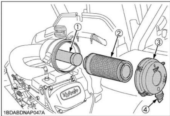
(1) Secondary (safety) element
(2) Primary element
(3) Cover
(4) Evacuator valve
IMPORTANT :
● The air cleaner uses a dry element, never apply oil.
- Do not run the engine with filter element removed.
- Be sure to refit the cover with the arrow (on the rear of cover) upright. If the cover is improperly fitted, evacuator valve will not function and dust will adhere to the element.
- Do not touch the secondary element except in cases where replacing is required.
◆Evacuator Valve
Open the evacuator valve once a week under ordinary conditions - or daily when used in a dusty place - to get rid of large particles of dust and dirt.
■Cleaning Engine Shroud Panel
If you feel you are unable to make the following service correctly and safely, contact your local KUBOTA Dealer.

CAUTION
To avoid personal injury:
● Make sure the engine is cool enough to touch before removing shrouds and other components.
● Always shield eyes and a face from air deposits and objects.
- Stop the engine and apply the parking brake.
- Open the hood.
- Pull the latch lever on the seat panel rearward.
- Raise the seat to the "LOCK" position.
- Loosen four bolts and remove the muffler cover.
- Loosen two screws (right & left) and remove the fan cover.

(1) Fan cover
(2) Screw
- Loosen four M6 bolts (right & left) and two M8 bolts and remove the cover.

(1) Cover
(2) M6 bolt
(3) M8 bolt

(1) Cover
(2) M6 bolt
- Remove large debris around the cooling fin and then blow off small debris with a compressed air. Pressure of compressed air must be under 205 kPa (2.1 kgf/cm², 30 psi).
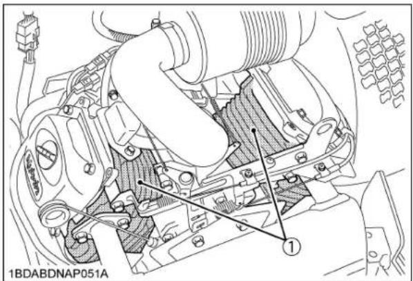
(1) Cooling fin
- Blow off the debris inside the fan cover as shown in the figure. Pressure of compressed air must be under 205 kPa (2.1 kgf/cm 2 , 30 psi).

(1) Fan cover
- Undo the rubber hook and open the air intake screen. Remove the debris on the surface of the air intake area by hand and blow off small debris with compressed air. Pressure of compressed air must be under 205 kPa (2.1 kgf/cm², 30 psi). Then clean them completely by pushing down the bottom clean lever several times. When using the bottom clean lever, remove the lever from the bracket. After cleaning, make sure that the lever is replaced in place.
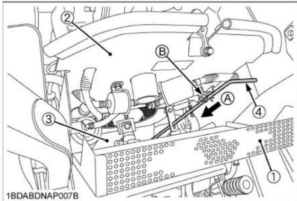
(1) Air intake screen
(2) Engine dust plate
(3) Dust cover
(4) Bottom clean lever
(A) "PUSH DOWN"
(B) Bracket
-
Install the cover with six bolts and then the fan cover with two screws.
-
Install the muffler cover with four bolts.
-
Pull up the seat support rod and release the "LOCK".
-
Lower the seat slowly to lock.
-
Close the hood.
■Cleaning Engine Oil Cooler Fins
[ZG227 only]
If you feel you are unable to make the following service correctly and safely, contact your local KUBOTA Dealer.
This engine is equipped with an oil cooler. The style of the oil cooler is mounted on the blower housing. Pressure of compressed air must be under 205 kPa (2.1 kgf/cm 2 , 30 psi).
![KUBOTA ZG227LA-60 - [ZG227 only] - 1](/content/2026/06/1369073/images/c0fe3ca0a37c99962a6dfe22d749720ea432f5dbf4f5b5641233d560687dff99.jpg)
CAUTION
To avoid personal injury:
● Make sure the engine is cool enough to touch before removing shrouds and other components.
● Always shield eyes and a face from air deposits and objects.
- Stop the engine and apply the parking brake.
- Loosen the two bolts for the engine oil cooler and remove the connector.

(1) Oil cooler
(2) Bolt
(3) Connector
- Pull out the engine oil cooler.

(1) Oil cooler
- Remove large debris from both sides of the engine oil cooler fin by hand, and then blow off small debris with the compressed air. Pressure of compressed air must be under 205 kPa (2.1 kgf/cm 2 , 30 psi).
- Remove the debris accumulated in the cooling air exit of the plate.

(1) Plate (A) Cooling air exit
- Put back the engine oil cooler in the original position, tighten bolts and connect the connector.
■ Checking Fuel Filter

CAUTION
To avoid personal injury:
-
Be sure to stop the engine and remove the key when attempting to make the following checks and changes.
● Never fail to check the fuel lines periodically. The fuel lines are subject to wear and aging. Fuel may leak out onto the running engine, causing a fire. -
The fuel line is made of rubber and ages regardless of service period.
- If the fuel line and clamps are found damaged or deteriorated, replace them.
- Check fuel filter bowl, if it is clogged by debris or contaminated with water, replace it.
IMPORTANT :
- When the fuel line is disconnected for maintenance or repair, close both ends of the fuel line with a piece of clean cloth or paper to prevent dust and dirt from entering. In addition, particular care must be taken not to admit dust and dirt into the fuel pump. Entrance of even a small amount dust or dirt causes premature wear and malfunction of the fuel pump and carburetor components.

(1) Pipe clamps
(2) Fuel line
(3) Fuel filter bowl
(4) Fuel filter

(1) Pipe clamps
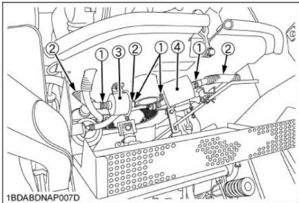
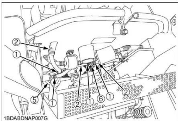
(1) Pipe clamps
(2) Fuel line
(3) Fuel pump
(4) Fuel filter
(5) Carbon canister
(6) Two way valve


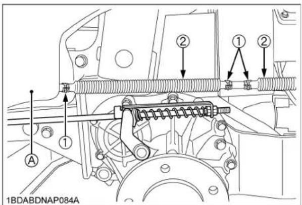
(1) Pipe clamps
(2) Fuel line
(A) Fuel tank
(B) Separator
■Cleaning Fuel Filter Bowl
Before supplying fuel, clean the fuel filter bowl.
IMPORTANT :
- If dirt or any other foreign matter is included in fuel, the filter element may be clogged earlier or water may be more likely to remain in the filter.
- If water remains in the fuel filter bowl, clean or replace the fuel filter bowl as early as possible.
◆Cleaning
- Change the carburetor fuel valve from the "RUN" (OPEN) position to the "STOP" (CLOSE) position.

(1) Carburetor fuel valve
(2) Ring screw
(3) Fuel filter bowl
(A) "STOP" (CLOSE)
(B) "RUN" (OPEN)
(C) "DRAIN"
- Loosen the ring screw and remove the fuel filter bowl.
- Remove the element and rinse it with gasoline. If the element is excessively dirty, replace it.
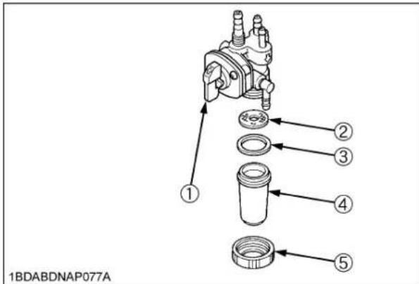
(1) Carburetor fuel valve
(2) Element
(3) Packing
(4) Fuel filter bowl
(5) Ring screw
IMPORTANT :
● Take care not to damage and misplace the element and packing.
- If they are excessively dirty (clogged), they will be clogged again in short hours after cleaning.
- Reassemble the packing and element while taking care that they are not contaminated with dirt.
IMPORTANT :
- If dirt is included in fuel, a failure can result.
NOTE :
- If the carburetor fuel valve is moved to the "DRAIN" position, the fuel will be drained through the drain port.

(1) Carburetor fuel valve
(2) Drain port
(A) "STOP" (CLOSE)
(B) "RUN" (OPEN)
(C) "DRAIN"
■Adjusting Parking Brake
If you feel you are unable to make the following service correctly and safely, contact your local KUBOTA Dealer.

CAUTION
To avoid personal injury:
● Park the machine on a firm and level surface.
- Stop the engine and chock the wheels before checking or adjusting.
IMPORTANT :
● Wrong adjustment may cause machine damage.
(1) Check brake spring
- Place the motion control levers to the "NEUTRAL LOCK" position.
- Be sure to chock the rear wheels.
- Apply the parking brake to the lock position.
- Check the length of the brake springs on both sides.
| (A): Proper brake spring length with the brake applied to the lock position | 115 to 117 mm(4.53 to 4.61 in.) |

(1) Brake rod
(A) "Parking brake spring length"
(2) Brake spring
(3) Lock nut
- If the length of the brake spring is not correct, adjust it.
(See "Adjustment of brake spring length" below.)
- Release the parking brake completely.
- Hold the brake rod lightly.
- Check the brake spring play.
| (B): Proper brake spring play | The spring must have play. Reference: 0.5 to 1.0 mm (0.02 to 0.04 in.) |
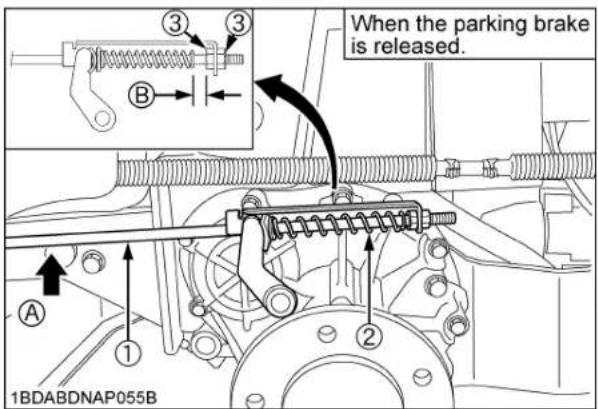
(1) Brake rod
(2) Brake spring
(3) Lock nut
(A) "Hold the brake rod"
(B) "Parking brake spring play"
- If the brake spring play is not correct, adjust it. (See "Adjustment of brake spring play" below.)
◆Adjustment of brake spring length
- Place the motion control lever to the "NEUTRAL LOCK" position.
- Apply the parking brake to the lock position.
- Loosen the lock nuts.
- Adjust the spring length to the recommendation.
- Lock the nuts.
- Check the brake spring play to the recommendation. If there is no play, adjust the brake spring play again. (See "Adjustment of brake spring play" below.)
- Adjust the other side spring to the same dimension.
◆Adjustment of brake spring play
- Place the motion control lever to the "NEUTRAL LOCK" position.
- Be sure to chock the rear wheels.
- Release the parking brake completely.
- Loosen the lock nuts.
- Hold the brake rod by hand.
- Tighten the nut to the correct space between the end of the spring and the nut.
- Lock the nuts.
- Adjust the other side spring to the same dimension.
(2) Check on the slope
- Place the machine on a 17 ramp.
- Apply the parking brake.
- Place the motion control levers in "NEUTRAL LOCK" position and shut off the engine.
- Check that the machine does not move.
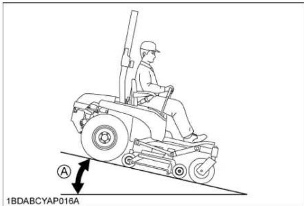
(A) 17° ramp
NOTE :
● For parking brake test purposes, only use 17 ramp.
■Battery Condition

DANGER
To avoid the possibility of battery explosion: For the refillable type battery, follow the instructions below.
- Do not use or charge the refillable type battery if the fluid level is below the LOWER (lower limit level) mark. Otherwise, the battery component parts may prematurely deteriorate, which may shorten the battery's service life or cause an explosion. Check the fluid level regularly and add distilled water as required so that the fluid level is between the UPPER and LOWER levels.

CAUTION
To avoid personal injury:
● Never remove the vent cap while the engine is running.
- Keep electrolyte away from eyes, hands and clothes. If you are spattered with it, wash it away completely with water immediately and get medical attention.
● Wear eye protection and rubber gloves when working around battery.
Mishandling the battery shortens the service life and adds to maintenance costs.
The original battery is a maintenance-free, non-accessible type battery.
If the battery is weak, the engine will be difficult to start and the lights will become dim. It is important to check the battery periodically.

(1) Battery
(2) Ground cable
(+): Positive terminal
(-): Negative terminal
◆Battery Charging

DANGER
To avoid serious injury or death:
- When the battery is being activated, hydrogen and oxygen gases in the battery are extremely explosive. Keep open sparks and flames away from the battery at all times, especially when charging the battery.

CAUTION
To avoid personal injury:
- When charging battery, ensure that the vent caps are securely in place (if equipped).
- When disconnecting the cables from the battery, start with the negative terminal first. When connecting the cables to the battery, start with the positive terminal first.
- Never check battery charge by placing a metal object across the posts. Use a voltmeter or hydrometer.
(For accessible maintainable type batteries with removable vent caps.)
- Make sure each electrolyte level is at the bottom of vent wells, if necessary add distilled water in a well-ventilated area.
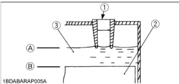
(1) Vent well
(A) "HIGHEST LEVEL"
(2) Separator
(B) "LOWEST LEVEL"
(3) Electrolyte
- The water in the electrolyte evaporates during recharging. Liquid shortage damages the battery. Excessive liquid spills over and damages the machine body.
- To slow charge the battery, connect the battery positive terminal to the charger positive terminal and the negative to the negative, then recharge in the standard fashion.
- A boost charge is only for emergencies. It will partially charge the battery at a higher rate and in a short time. When using a boost-charged battery, it is necessary to recharge the battery as soon as possible.
Failure to do this will shorten the battery's service life. -
When the specific gravity of electrolyte reaches 1.27-1.29 charge has completed.
-
When exchanging an old battery with new one, use a battery of equal specification shown in "SPECIFICATIONS".
(For non-accessible maintenance-free type batteries.) Maintenance-free, non-accessible batteries are designed to eliminate the need to add water. Yet the volume of electrolyte above plates may eventually become depleted due to abnormal conditions such as high heat or improper regulator setting. Use a voltmeter to check the state of charge. (See reference chart below to determine if charging is necessary.)
| Battery voltage Reference state of charge | |
| 12.6 100% (Full charge) | |
| 12.4 75% | |
| 12.2 50% | |
| 12.0 25% | |
| 11.8 0% | |
■Adjusting Throttle Cable
- Move the throttle lever to the top position.

(1) Throttle lever
- Make sure a part (2) is touching the restricting bolt (1).
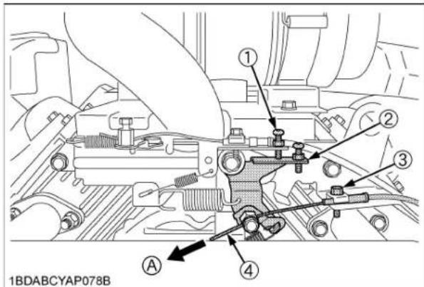
(1) Restricting bolt
(A) "PULL"
(2) Part
(3) Bolt
(4) Throttle lever cable
- If not, loosen the bolt (3) and pull the throttle lever cable (4) in direction of the arrow (A) so that the part (2) would touch the restricting bolt (1). And then tighten the bolt (3).
■Checking Carbon Canister Air Filter
If you feel you are unable to make the following service correctly and safely, contact your local KUBOTA Dealer.
Check the carbon canister air filter every 100 hours of operation. (more often under extremely dusty or dirty conditions.)

CAUTION
To avoid personal injury:
● Always stop the engine, set the parking brake, remove the key, and disengage PTO.
- Open the air intake screen.
- Remove the cover and remove the carbon canister air filter.

(1) Canister air filter
(2) Cover
(3) Carbon canister
(A) Air intake screen
(B) Air port
-
Check to see if the carbon canister air filter is worn out, damaged or dirty.
-
If the air filter is dirty, wash the air filter in warm water with detergent. Then rinse the air filter thoroughly until all traces of detergent are eliminated. Squeeze out excess water. (do not wring.) Allow the air filter to air dry. Do not use high pressure air to clean filter.
-
If the air filter is worn out, damaged or too dirty to wash clean, replace it with a new one.
-
Reinstall the carbon canister air filter and secure it with the cover.
NOTE :
- Operating in dusty condition may require more frequent maintenance than above.
EVERY 150 HOURS
■Changing Gear Box Oil

CAUTION
To avoid personal injury:
● Be sure to stop the engine and remove the key before changing the oil.
If serial numbers of mower are as indicated below RCK48S-222Z:all
- To drain the used oil, remove the oil inlet plug at the gear box, tilt the mower deck and drain the oil completely into the oil pan.
- Fill with the new oil up to the check plug port. (See "LUBRICANTS AND FUEL" in "MAINTENANCE" section.)
- After filling reinstall the oil inlet plug and the check plug.
![[RCK48S] ① ② 1BDABBSAP106B](/content/2026/06/1369073/images/95d5fdcc4b8bc2fa2e5a53ec74ff8dd70cf197fe955711e57b766c8d96484f3a.jpg)
(1) Check plug
(2) Oil inlet plug
If serial numbers of mower are as indicated below
RCK48P-222Z:30000 and below
RCK54P-227Z:30000 and below
RCK60P-227Z:30000 and below
- To drain the used oil, remove the drain plug and oil inlet plug at the gear box and drain the oil completely into the oil pan.
- After draining reinstall the drain plug.
- Remove the oil level check plug.
- Fill with the new oil up to the check plug port. (See "LUBRICANTS AND FUEL" in "MAINTENANCE" section.)
- After filling reinstall the check plug and oil inlet plug securely.
![[RCK48P, RCK54P, RCK60P] ③ ④ ② ① 1BDABCVAP057C](/content/2026/06/1369073/images/77f9fb4cdd6623b4d592103de3630fe1194082f982055125be37c5e1ef75e96c.jpg)
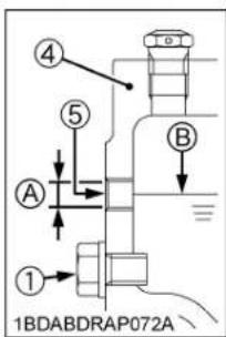
(1) Drain plug
(2) Check plug
(3) Oil inlet plug
(4) Gear case
(5) Check plug port
(A) Oil level is acceptable within this range.
(B) Oil level
If serial numbers of mower are as indicated below
RCK48P-222Z:30001 and above
RCK54P-227Z:30001 and above
RCK60P-227Z:30001 and above
- To drain the used oil, remove the drain plug and oil inlet plug with gauge at the gear box and drain the oil completely into the oil pan.
- After draining reinstall the drain plug.
- Remove the oil level check plug.
- Fill with the new oil up to the check plug port. (See "LUBRICANTS AND FUEL" in "MAINTENANCE" section.)
- After filling reinstall the check plug and oil inlet plug with gauge securely.
![[RCK48P, RCK54P, RCK60P] ① ② ③ ④ 1BDABDRAP034E](/content/2026/06/1369073/images/b1c5fc13cc47f88a096bc74bb121f43873a0b423f0d73ce0d1b4ee006e5b2130.jpg)

(1) Drain plug
(2) Check plug
(3) Oil inlet plug with gauge
(4) Gear case
(5) Check plug port
(A) Oil level is acceptable within this range.
(B) Oil level
EVERY 200 HOURS
■Replacing Engine Oil Filter

CAUTION
To avoid personal injury:
- Be sure to stop the engine and remove the key before changing the oil and the oil filter.
-
Allow engine to cool down sufficiently; oil can be hot and may cause burns.
-
The oil filter must be changed every 200 service hours.
- Apply a slight coat of oil onto the rubber gasket of new filter.
- Tighten the filter quickly until it contacts the mounting surface. Tighten filter by hand an additional 1/2 turn only.
- After the new filter has been replaced, the engine oil level normally lowers a little. Add engine oil to proper level. Check for oil leaks around filter gasket.
IMPORTANT :
● To prevent serious damage to the engine, replacement element of the recommended type must be used. Use only a genuine KUBOTA filter or its equivalent.
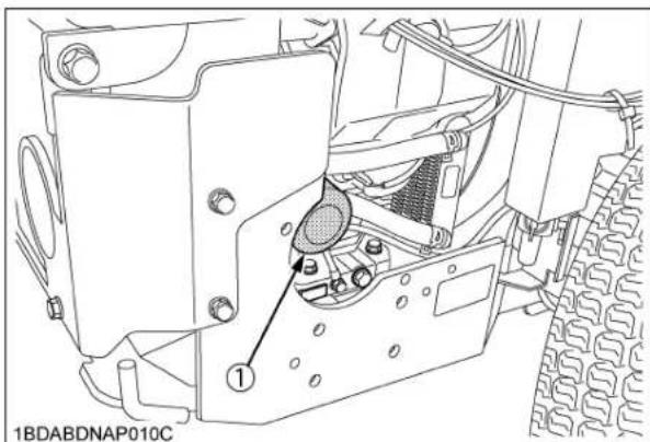
(1) Engine oil filter
■Checking Spark Plug Condition & Gap
Remove the spark plugs, check condition, and reset the gap or replace with new plugs as necessary.
- Open the hood.
- Before removing spark plugs, clean the area around the base of the plug to keep dirt and debris out of the engine.
- Disconnect the spark plug cap from spark plugs.
- Use a spark plug wrench to remove the spark plugs.
- Remove plugs and check its condition.
Replace the plug if worn or reuse is questionable. - Inspect spark plugs for cracked porcelain, pitted electrodes, or other wear and damage. Replace the spark plug if necessary.

(1) Spark plug cap and spark plug
NOTE :
- Do not clean the spark plug in a machine using abrasive grit. Some grit could remain in the spark plug and enter the engine, which may cause extensive wear and damage.
Recommended spark plug NGK BPR6HS
- Check the gap using a wire feeler gauge. Adjust the gap from 0.6 to 0.7 mm (0.024 to 0.028 in.) by carefully bending the ground electrode.
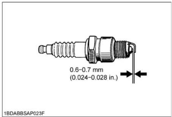
- Reinstall the spark plug into the cylinder head.
| Tightening torque | 9.8 to 19.6 N-m(7.2 to 14.5 lbf-ft) |
■Replacing Transmission Oil Filter Cartridge

CAUTION
To avoid personal injury:
- Be sure to stop the engine and remove the key before changing the oil filter.
-
Allow transmission case to cool down sufficiently; oil can be hot and may cause burns.
-
The oil filter cartridge must be changed every 200 service hours.

natural_image
Technical line drawing of a mechanical assembly with labeled components (no readable text or symbols)(1) Oil filter cartridge
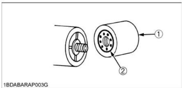
(1) Oil filter cartridge (2) Gasket
- Place an oil pan underneath the oil filter cartridge. (Do not drain oil.)
- Remove the oil filter cartridge by using the filter wrench.
- Apply a slight coat of oil onto the gasket of new filter.
- Tighten the filter quickly until it contacts the mounting surface. Tighten filter by hand an additional 1/2 turn only.
- After the new cartridge has been replaced, the transmission fluid level normally lowers a little. Add fluid to proper level. Check for oil leaks around filter gasket.
IMPORTANT :
● To prevent serious damage or premature failure to the hydraulic system, use only a KUBOTA genuine filter.
■Adjusting the Motion Control Lever Pivot

CAUTION
To avoid personal injury:
- Be sure to stop the engine and set the parking brake to "ON" before checking.
| Proper lever free travel | 2 to 15 mm (0.08 to 0.59 in.) on the lever |
- Set the motion control lever in "NEUTRAL" position.
- Slightly move the lever back and forth and measure the free travel at the top of lever stroke.
- If the proper free travel limits are exceeded, remove the fender and retighten only the upper nut to specified torque.
NOTE :
- If the motion control lever pivot bolt is maladjusted, motion control may be difficult.

(1) Motion control lever
(2) Bolt, Nut
(A) "FREE TRAVEL"
| Tightening torque | 18.6 to 20.6 N-m(1.9 to 2.1 kgf-m,13.7 to 15.2 lbf-ft) |
■Cleaning Engine Shroud
Consult your local KUBOTA Dealer for this service.
EVERY 400 HOURS
■Changing Transmission Fluid and Rear Axle Gear Case Oil (RH and LH)

CAUTION
To avoid personal injury:
● Park the machine on a firm and level surface.
- Be sure to stop the engine and remove the key before changing or checking the oil.
- Allow transmission case to cool down sufficiently; oil can be hot and may cause burns.
The fluid in the transmission case is also used for the hydrostatic drive system.
- To drain the transmission oil, place the oil pan underneath the transmission case and remove the drain plugs at the bottom of the transmission case.

(1) Drain plug of center case
- After draining, open the air intake screen. Remove the snap pin and push down the bottom clean lever to open the dust cover; set the snap pin into the original hole of the lever under the stay to keep the dust cover open.

(1) Bottom clean lever
(2) Snap pin
(3) Stay
(A) Air intake screen
(B) Dust cover
(P) "PUSH DOWN"
- Disassemble and clean the strainer and change the oil filter cartridge. After reassembling, fill with UDT or SUPER UDT hydrostatic transmission fluid, or its equivalent.

(1) Transmission strainer (A) Bottom clean lever
(B) Dust cover
- After running the engine for a few minutes, stop it and check the oil level again; add oil to the prescribed level.
IMPORTANT :
- Operate only at low rpms immediately after changing the transmission fluid and the filter cartridge. Keep the engine at medium speed for a few minutes to insure proper lubrication of all parts so there is no damage to the transmission.

(1) Drain plug of axle case (on both sides)

(1) Transmission oil filter

(1) Oil level dipstick
(2) Oil plug and breather cup
(A) Oil level is acceptable within this range.
■Cleaning Transmission Strainer
When changing the transmission fluid, disassemble and rinse the strainer with nonflammable solvent to completely clean off filings.
Check O-rings, replace if damaged, cracked or hardened. When reassembling be careful not to damage the parts.
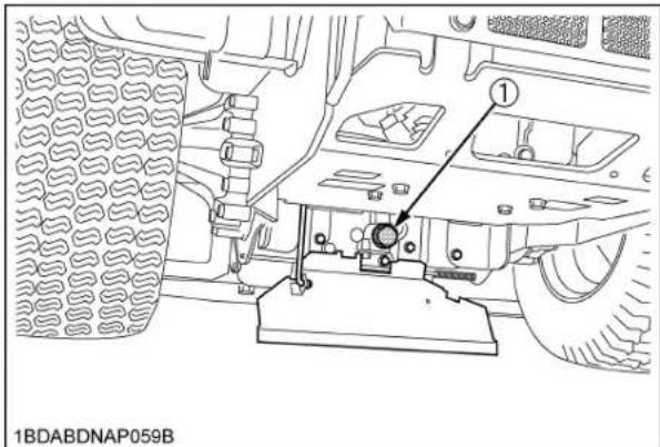
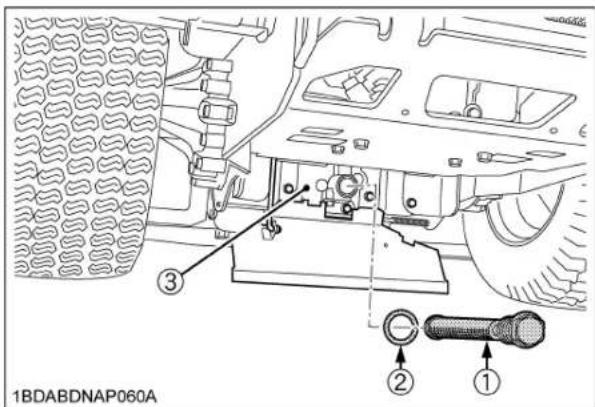
(1) Transmission strainer
(2) O-ring
(3) Center case cover
NOTE :
- Since the fine filings in the oil can damage the precision component parts of the hydraulic system, the end of the suction line is provided with an oil strainer.
■Replacing Fuel Filter
Consult your local KUBOTA Dealer for this service.
EVERY 500 HOURS
■Adjusting Engine Valve Clearance
If you do not have the proper tools and/or are not mechanically proficient, consult your local KUBOTA Dealer for this service.
EVERY AFTER 1000 HOURS
■Cleaning Combustion Chamber
If you do not have the proper tools and/or are not mechanically proficient, consult your local KUBOTA Dealer for this service.
EVERY 1000 HOURS or EVERY 1 YEAR
Replace every 1000 hours or every 1 year whichever comes faster.
■Replacing Air Cleaner Primary Element and Secondary Element
(See "Cleaning Air Cleaner Primary Element" in "EVERY 100 HOURS" in "PERIODIC SERVICE" section.)
IMPORTANT :
● To prevent serious damage to the engine, use only a KUBOTA genuine filter.
[How to remove the secondary element]
- While turning slightly, pull out the secondary element.
![KUBOTA ZG227LA-60 - [How to remove the secondary element] - 1](/content/2026/06/1369073/images/43c626046a2889f3824840a28136ca26a6faa50d4c961f5688bd36884c4e257e.jpg)
natural_image
Technical illustration of a cylindrical mechanical component with internal threading and a separate cylindrical housing, labeled with number 1 (no text or symbols on the diagram itself)(1) Secondary element
EVERY 1 YEAR
■ Checking Fuel Lines
If you feel you are unable to make the following service correctly and safely, contact your local KUBOTA Dealer.
(See "Checking Fuel Filter" in "EVERY 100 HOURS" in "PERIODIC SERVICE" section.)
■ Checking Hydraulic Hose
If you feel you are unable to make the following service correctly and safely, contact your local KUBOTA Dealer.

CAUTION
To avoid personal injury:
- Be sure to stop the engine, remove the key, and relieve pressure before checking and replacing the hydraulic hose.
-
Allow the transmission case to cool down sufficiently; oil can be hot and may cause burns.
-
Check to see that all lines and hose clamps are tight and not damaged.
- If hoses and clamps are found worn or damaged, replace or repair them at once.

(1) Mower lift cylinder hose
-
Escaping hydraulic fluid under pressure has sufficient force to penetrate the skin causing serious personal injury. Before disconnecting lines, be sure to relieve all pressure. Before applying pressure to the system, make sure all connections are tight and that lines, pipes, and hoses are not damaged.
-
Fluid escaping from pinholes may be invisible. Use a piece of cardboard or wood to search for suspected leaks: do not use hands. Use safety goggles or other eye protection.
If injured by escaping fluid, see a medical doctor at once. Serious infection or reaction will result if proper medical treatment is not administered immediately.
This fluid can produce gangrene or severe allergic reaction.
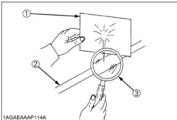
(1) Cardboard
(2) Hydraulic line
(3) Magnifying glass
■ Checking Intake Air Line
If you feel you are unable to make the following service correctly and safely, contact your local KUBOTA Dealer.
- Check to see that hoses and hose clamps are tight and not damaged.
- If hoses and clamps are found worn or damaged, replace or repair them at once.

(1) Hose
(2) Clamp
■ Checking Engine Breather Hose
Consult your local KUBOTA Dealer for this service.
■ Checking Mower Gear Box Oil Seal
Consult your local KUBOTA Dealer for this service.
EVERY 2 YEARS
■Replacing Carbon Canister Air Filter
If you feel you are unable to make the following service correctly and safely, contact your local KUBOTA Dealer.
(See "Checking Carbon Canister Air Filter" in "EVERY 100 HOURS" in "PERIODIC SERVICE" section.)
EVERY 4 YEARS
■Replacing Hydraulic Hose
Consult your local KUBOTA Dealer for this service.
■Replacing Fuel Lines
Consult your local KUBOTA Dealer for this service.
■Replacing Engine Breather Hose
Consult your local KUBOTA Dealer for this service.
■Replacing Mower Gear Box Oil-Seal
Consult your local KUBOTA Dealer for this service.
■Replacing Intake Air Line
If you feel you are unable to make the following service correctly and safely, contact your local KUBOTA Dealer.
See "Checking Intake Air Line" in "EVERY 1 YEAR" in "PERIODIC SERVICE" section.
SERVICE AS REQUIRED
■Replacing Fuses
- Raise the operator's seat.
- Remove the blown fuse.
- Place a new fuse of the same capacity in position.
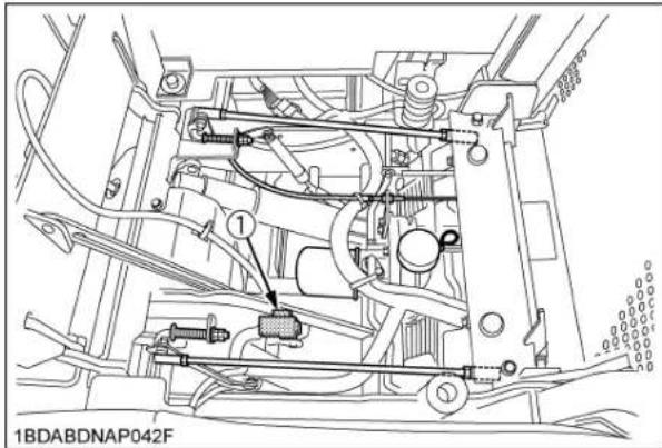
(1) Fuse location
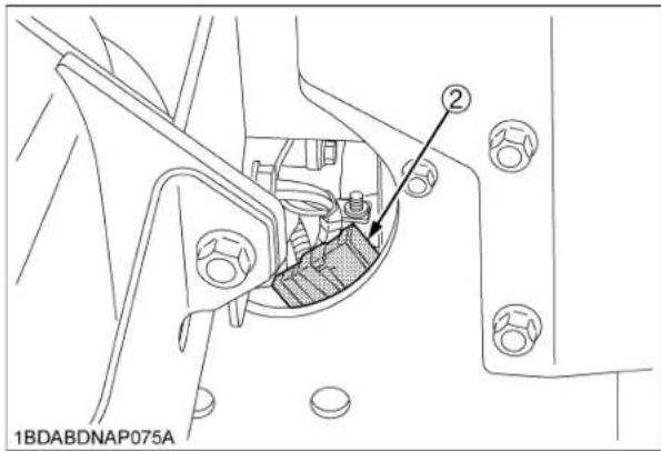
(2) Slow blow fuse
IMPORTANT :
- If the new fuse happens to blow out within a short time, contact your dealer for inspection and repair. Never "jump" the fuse with wire or foil, or install a larger capacity fuse than is recommended.
◆Protected circuit
| FUSE NO. | CAPACITY (A) | Protected circuit |
| (1) | 15 Main system | |
| 15 Aux. outlet | ||
| 10 Control system | ||
| 20 * (Work light) | ||
| - | - | |
| - | - | |
| (2) | Slow blow fuse 50 | Check circuit against wrong battery connection |
*Option: The fuse should be in only when the work light is attached.
■ Checking and Replacing Blade

CAUTION
To avoid personal injury:
- Be sure to stop the engine and remove the key.
- Blades may be sharp. When you handle blades, wear heavy gloves or wrap end of blade with a rag.
NOTE :
● Before checking or replacing the blade, wipe grass and mud off the top and inside of the mower. Especially clean up the inside of the belt cover, because otherwise the belt life will be reduced.
◆Checking
The blade cutting edges should be kept sharp at all times. Sharpen the cutting edges, if they resemble blade (B). Replace the blades if they appear similar to blade (C).

(A) New blade
(B) Worn blade
(C) Cracked blade
◆Replacing
-
Dismount the mower deck from the machine. (See "DISMOUNTING THE MOWER DECK" in "MOWER MOUNTING" section.) Then turn it over to expose the blades.
-
Wedge a block of wood between the blade and mower housing or use a box wrench over the pulley nut to prevent the spindle from rotating while removing the blade bolts; loosen the blade bolt as illustrated.
IMPORTANT :
- Use the proper metric size box or socket wrench to tighten or loosen the blade mounting bolt.

(1) Block (A) "LOOSEN"
- To sharpen the blades yourself, clamp the blade securely in a vise.
Use a large mill file and file along the original bevel until sharp.
-
To check the blade for balance, place a small rod through the center hole. If the blade is not balanced, file the heavy side of the blade until balance is achieved.
-
[RCK48S]
Pass the bolt through the blade and the cup washer, and tighten the bolt.
[RCK48P, RCK54P]
Pass the bolt through the blade, 2 cup washers and the lock washer, and tighten the bolt.
[RCK60P]
Pass the spline boss through the blade and 2 cup washers, and tighten the bolt.
NOTE :
● Make sure that the cup washer is not flattened out or worn; this cause blade to slip excessively.
Replace the 2 cup washers if either is damaged.
[RCK48S]

(1) Spindle holder
(2) Cover
(3) Blade
(4) Cup washer
(5) Bolt
[RCK48P, RCK54P]

(1) Spindle holder
(2) Spindle guard
(3) Blade
(4) 2-Cup washer
(5) Lock washer
(6) Bolt
[RCK60P]

(1) Spindle holder
(2) Blade
(3) 2-Cup washers
(4) Spline boss
(5) Bolt
(6) Spindle guard
IMPORTANT :
● Tighten the bolts of the outer blades from 103 to 118 N-m (76 to 87 lbf-ft) of torque.
● The blade bolts have Right hand threads. Turn them counterclockwise to loosen.
● To prolong the service life of the blades, reposition them as shown in the figure below periodically.

flowchart
graph TD
    A["①"] --> B["②"]
    B --> C["③"]
    C --> D["④"]
    D --> A
    style A fill:#f9f,stroke:#333
    style B fill:#bbf,stroke:#333
    style C fill:#bfb,stroke:#333
(1) LH blade
(2) Center blade
(3) RH blade
■Replacing Mower Belt
- Remove the mower deck from the machine according to the procedure "DISMOUNTING THE MOWER DECK".
- Remove the left and right hand shield from the mower deck.
- Clean around the gear box.
- Remove the belt from the tension pulley.
- Remove the right hand bracket which mounts the gear box to the mower deck and slip the belt over the top of the gear box.
- To install a new belt, reverse the above procedure.
NOTE :
● Tighten bracket bolts and nuts securely 77.6 to 90.2 N-m (8.0 to 9.2 kgf-m, 57.1 to 66.5 lbf-ft).

(1) Tension pulley
(4) Bolt
(2) Bracket (RH)
(5) Nut
(3) Belt
■Bleeding Fuel System
Air must be removed:
- When the fuel filter or lines are removed.
- When tank is completely empty.
- After the machine has not been used for a long period of time.
◆Bleeding procedure is as follows:
- Fill the fuel tank with appropriate fuel.
- Turn the key switch to the "ON" position and hold it for about 10 seconds.
- Start the engine and run for about 30 seconds, and then stop the engine.
ADJUSTMENT
To avoid personal injury:
● Park the machine on a firm and level surface.
- If it is necessary to run the engine in an enclosed area, use a gas tight exhaust pipe extension to remove the fumes.
● Always try to work in a well-ventilated area.
- Lift up and secure with jack stands or blocking the rear of the machine, do not run the machine while adjusting. Remove rear wheels.
- Do not adjust only one of the following adjustments; exclude "MOTION CONTROL LEVER ALIGNMENT". They are interlinked.
- If you feel you are unable to make the following adjustments correctly and safely, contact your local KUBOTA Dealer.
IMPORTANT :
● Right and left motion control levers can be adjusted independently.
● This machine has a creep speed.
■HST NEUTRAL
- Lift-up and secure with jack stands or blocking the rear of the machine frame.
- Remove both rear wheels.
- Start the engine, and run at maximum speed.
- Remove the lever guide.
- Place the motion control lever in "NEUTRAL LOCK" position.
- Check that the lever is touching the front side of its guide plate. If the lever is not in the correct position, adjust the speed control spring. See "CREEP SPEED".
- Remove the set knobs of seat frame, then raise and latch the seat assembly.
- Remove the connector from the seat safety switch, and then temporarily install a jumper wire across the terminals in the connector of the wiring harness.

CAUTION
To avoid personal injury:
- Do not operate the machine with a jumper wire.
-
Loosen the lock nut of the motion control rod. Adjust the motion control rod until the rear axle rotation stops.
-
Lengthen the rod by 1/2 turn and then tighten the lock nut.
Place the motion control lever to the reverse position, and move them to the forward slowly. - Place the lever in "NEUTRAL LOCK" position, and check that the rear axle does not rotate. If the axle does not stop rotating, adjust the "HST NEUTRAL" again.
- Adjust the other side "HST NEUTRAL" equally.
- After adjustment, make sure to stop the engine immediately.

natural_image
Mechanical assembly diagram showing a lever mechanism with a directional arrow (no text or symbols present)(1) Guide plate
(2) Motion control lever
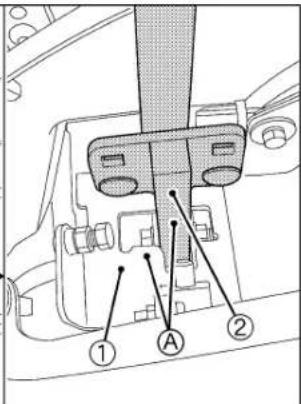
(A) The lever is in contact with plate.

(1) Motion control rod
(2) Lock nut
(3) Beam plate
(4) Panel screen
CREEP SPEED
- Lift-up and secure with jack stands or blocking the rear of the machine frame.
- Remove both rear wheels.
- Start the engine, and run at maximum speed.
- Place the lever in "NEUTRAL" position.
- Pull the lever to the reverse maximum position and release the lever.
- Measure the axle rotation.
- Loosen the lock nut and adjust the creep speed control bolt length so that the axle rotation is between 8 to 10 revolutions per minute. (Do not change spring length L=55 to 56 mm (2.17 to 2.2 in.))
- Tighten the lock nut.
- Check the axle creep rpm again. If it is not correct, adjust again.
- Adjust the other side "CREEP SPEED" equally.
- After adjustment, make sure to stop the engine immediately.

(1) Lock nut
(L) 55 to 56 mm (2.17 to 2.2 in.)
(2) Creep speed control bolt
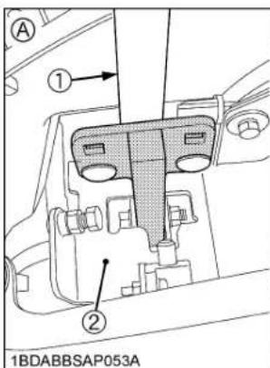
(1) Motion control lever
(2) Guide plate
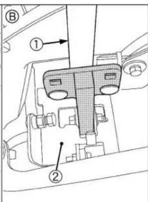
(A) "CREEP" position (hands off)
(B) "NEUTRAL" position (held by hands)
■MAXIMUM SPEED (FORWARD)
Consult your local KUBOTA Dealer for this service.
◆Check the alignment
Check the gap and space between the levers, at the maximum forward position.
| Recommendation | Gap: 0 to 2 mm(0 to 0.08 in.)Space:10 to 20 mm(0.4 to 0.8 in.) |
If positions of the control levers are unequal, an adjustment is necessary.
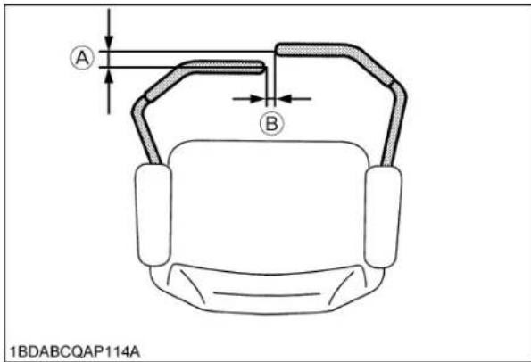
(A) "GAP"
(B) "SPACE"

CAUTION
To avoid personal injury:
● Park the machine on a firm and level surface.
- Stop the engine, remove the key and apply the parking brake.
◆Aligning the control levers
- Stop the engine and apply the parking brake.
- Loosen the screws and remove the lever guide.
Lever position (High or Low)
-
Remove the bolts and select the motion control lever position, high or low.
-
Tighten the bolts.

(1) Bolt
(A) High position
(2) Flange nut
(3) Tab slot
Lever alignment (Right and Left)
- Loosen the bolts.
- Slide both levers forward or rearward to the desired position within tab slots until levers are aligned.
- Tighten the bolts.
- Install the lever guide with the screws and tighten them securely.
NOTE :
- If the ends of the levers strike against each other while in "NEUTRAL" position, move the levers outward to the "NEUTRAL LOCK" position and carefully bend them outward. Move them back to the "NEUTRAL" position and check for the recommended space.
MOWER DECK LEVEL
ANTI-SCALP ROLLERS

CAUTION
To avoid personal injury:
● Park the machine on a firm and level surface.
- Apply the parking brake.
- Stop the engine and remove the key.
● Wait for all moving parts to stop.
IMPORTANT :
● The flattest cut can be achieved by having the anti-scalp rollers adjusted off the ground.
Check anti-scalp roller adjustments each time the mower deck cutting height is changed.
It is recommended that all the anti-scalp rollers be kept off the ground to minimize scuffing.
-
Check the machine tire pressure. Inflate tires to the correct pressure. (See "TIRES AND WHEELS" section.)
-
Start the engine.
-
Raise up the mower deck to the transport position. (Also the top end of the lift.)
-
Turn the cutting height control dial to adjust height.
-
Lower the mower deck.
Front side anti-scalp roller
- Adjust the height of the front side anti-scalp roller to one of three positions to approximately 19 mm (3/4 in.) between rollers and the ground. Adjust both side rollers to the same height.

(H) 19 mm (3/4 in.)
- Install the roller with attaching hardware.
Rear side anti-scalp roller
- Adjust the height of the rear side anti-scalp roller to one of three positions to approximately 19 mm (3/4 in.) between rollers and the ground. Adjust both side rollers to the same height.

natural_image
Technical diagram of a mechanical assembly with a circular component and a base, no visible text or symbols(H) 19 mm (3/4 in.)
- Install the roller with attaching hardware.
■LEVEL MOWER DECK (Side-to-Side)

CAUTION
To avoid personal injury:
● Park the machine on a firm and level surface.
- Apply the parking brake.
● Disengage PTO (OFF).
- Stop the engine, remove the key and remove the mower universal joint while checking or adjusting the level of the mower deck.
IMPORTANT :
- Check the machine tire pressure. Inflate tires to the correct pressure. (See "TIRES AND WHEELS" section.)
◆Checking level (Side-to-Side)
NOTE :
● Mower deck anti-scalp rollers should not contact the ground.
- Raise the mower deck to the transport position. (Also the top end).
- Turn the cutting height set dial to the 3 in. cutting height position.
- Lower the mower deck.
- Position the right mower blade in the Side-to-Side position.
- Measure from outside blade tip to the level surface with a short ruler or leveling gauge.
Reference
| Height of the blade at the concrete surface | 76 mm (3 in.) |
NOTE :
● There is a difference of the blade height between on the concrete and ground.
6. Check that the left side blade is same height.
The difference between both measurements should be less than 3 mm (1/8 in.).
7. If the Side-to-Side adjustment is not within the given tolerance, adjustment is necessary.
Side-to-Side adjustment Less than 3 mm (1/8 in.)
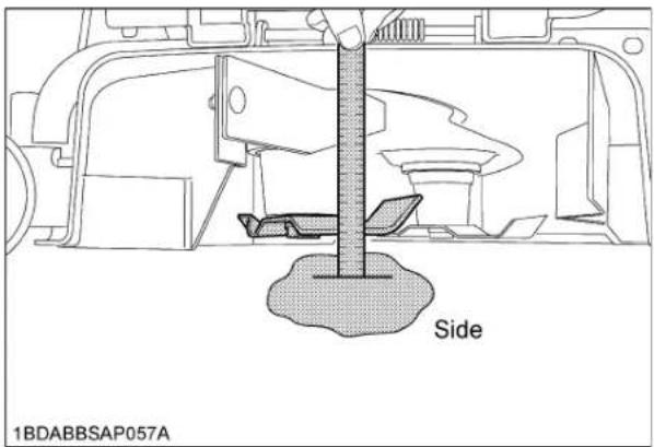
◆Adjusting level (Side-to-Side)
- Raise up the mower deck to the transport position. (Also the top end).
- Turn the cutting height set dial to the 3 in. cutting height position.
- Place 51 mm (2 in.) height wood blocks under each side of the mower deck. Anti-scalp rollers must not rest on the wood block.
- Lower the mower deck.
- Position mower blade in the Side-to-Side position.
- Loosen the lock nuts of the right side of the machine.
- Adjust the cutting height fine tuning bolts to set 76 mm (3 in.) height. Front and rear side bolts must be adjusted.
- Lock the nuts.
- Adjust the left side equally.
- Check the side-to-side level and if it is not level, adjustment is necessary.

(1) Cutting height fine tuning bolt
(2) Lock nut
■LEVEL MOWER DECK (Front-to-Rear)

CAUTION
To avoid personal injury:
● Park the machine on a firm and level surface.
● Engage the parking brake.
● Disengage PTO.
- Stop the engine, remove the key and remove the mower universal joint while checking or adjusting the level of the mower deck.
IMPORTANT :
- Check the machine tire pressure. Inflate tires to the correct pressure
(See "TIRES AND WHEELS" section.)
◆ Checking level (Front-to-Rear)
NOTE :
● Mower deck anti-scalp rollers should not contact the ground.
- Raise the mower deck to the transport position. (Also the top end).
- Turn the cutting height set dial to the 3 in. cutting height position.
- Lower the mower deck.
- Position the right mower blade in the Front-to-Rear position.
- Measure from the right front blade tip to the level surface with a short ruler or leveling gauge.
- Turn the blade 180 and measure from right rear blade tip to the level surface.
- Check that the left side blade has the same dimension. The difference between both measurements should be less than 6 mm (1/4 in.). Front side must be lower than rear side.
- If the Front-to-Rear adjustment is not within the given tolerance, adjustment is necessary.

(A) Front
(B) Rear
| Front-to-Rear adjustment | Less than 6 mm (1/4 in.) Front side must be lower than Rear side. |
◆Adjusting level (Front-to-Rear)
-
Raise up the mower deck to the transport position. (Also the top end).
-
Turn the cutting height set dial to the 3 in. cutting height position.
-
Place 51 mm (2 in.) height wood blocks under each side of the mower deck.
Anti-scalp rollers must not rest on the wood block.
-
Lower the mower deck.
-
Loosen the lock nuts of the front side of the machine.
-
Adjust the cutting height fine tuning bolts to set 76 mm (3 in.) height.
Both front side bolts must be adjusted.
-
Lock the nuts.
-
Adjust the other side equally.
IMPORTANT :
● The difference between both measurements should be less than 6 mm (1/4 in.).
Front side must be lower than rear side.
- Check the front-to-rear level and if it is not level, adjustment is necessary.

(1) Cutting height fine tuning bolt
(2) Lock nut
GENERAL TORQUE SPECIFICATION
| American standard cap screws with UNC or UNF threads | Metric cap screws | ||||||
| SAE grade No. | GR.5 GR.8 |  | Property class | Class 8.8 Class  | 10.9 | ||
| 1/4 | (lbf-ft) | 8 - 9.6 | 12 - 14.4 | M6 | (lbf-ft) | 7.2 - 8.3 | |
| (N-m) | 10.7 - 12.9 | 16.1 - 19.3 | (N-m) | 9.81 - 11.3 | |||
| (kgf-m) | 1.11 - 1.33 | 1.66 - 1.99 | (kgf-m) | 1.0 - 1.15 | |||
| 5/16 | (lbf-ft) | 17 - 20.5 | 24 - 29 | M8 | (lbf-ft) | 17.4 - 20.2 | 21.7 - 25.3 |
| (N-m) | 23.1 - 27.8 | 32.5 - 39.3 | (N-m) | 23.6 - 27.4 | 29.4 - 34.3 | ||
| (kgf-m) | 2.35 - 2.84 | 3.31 - 4.01 | (kgf-m) | 2.4 - 2.8 | 3.0 - 3.5 | ||
| 3/8 | (lbf-ft) | 35 - 42 | 45 - 54 | M10 | (lbf-ft) | 35.5 - 41.2 | 44.9 - 52.1 |
| (N-m) | 47.5 - 57.0 | 61.0 - 73.2 | (N-m) | 48.1 - 55.8 | 60.8 - 70.5 | ||
| (kgf-m) | 4.84 - 5.82 | 6.22 - 7.47 | (kgf-m) | 4.9 - 5.7 | 6.2 - 7.2 | ||
| 1/2 | (lbf-ft) | 80 - 96 | 110 - 132 | M12 | (lbf-ft) | 57.2 - 66.5 | 76.0 - 86.8 |
| (N-m) | 108.5 - 130.2 | 149.2 - 179.0 | (N-m) | 77.5 - 90.1 | 103 - 117 | ||
| (kgf-m) | 11.07 - 13.29 | 15.22 - 18.27 | (kgf-m) | 7.9 - 9.2 | 10.5 - 12.0 | ||
| 9/16 | (lbf-ft) | 110 - 132 | 160 - 192 | M14 | (lbf-ft) | 91.2 - 108 | 123 - 144 |
| (N-m) | 149.2 - 179.0 | 217.0 - 260.4 | (N-m) | 124 - 147 | 167 - 196 | ||
| (kgf-m) | 15.22 - 18.27 | 22.14 - 26.57 | (kgf-m) | 12.6 - 15.0 | 17.0 - 20.0 | ||
| 5/8 | (lbf-ft) | 150 - 180 | 220 - 264 | M16 | (lbf-ft) | 145 - 166 | 192 - 224 |
| (N-m) | 203.4 - 244.1 | 298.3 - 358.0 | (N-m) | 196 - 225 | 260 - 303 | ||
| (kgf-m) | 20.75 - 24.91 | 30.44 - 36.53 | (kgf-m) | 20.0 - 23.0 | 26.5 - 31.0 | ||
TIGHTENING TORQUE CHART
| Thread size d (mm) | Hexa-Bolt Head size B (mm) | No mark 7T | |||||
| lbf-ft N-m | kgf-m lbf-ft N-m | kgf-m | |||||
| M8 12 or 13 | 13.0 - 15.2(14.1 1 1) | 17.8 - 20.6(19.2 1 4) | 1.9 - 2.1(2.0 0 1) | 17.5 - 20.3(18.9 1 4) | 23.5 - 27.5(25.5 2 0) | 2.4 - 2.8(2.6 0 2) | |
| M10 14 or 17 | 28.9 - 33.3(31.1 2 2) | 39.3 - 45.1(42.2 2 9) | 4.0 - 4.6(4.3 0 3) | 35.4 - 41.2(38.3 2 9) | 48.1 - 55.9(52.0 3 9) | 4.9 - 5.7(5.3 0 4) | |
| M12 17 or 19 | 46.3 - 53.5(49.9 3 6) | 62.8 - 72.6(67.7 4 9) | 6.4 - 7.4(6.9 0 5) | 57.1 - 66.5(61.8 4 7) | 77.6 - 90.2(83.9 6 3) | 8.0 - 9.2(8.6 0 6) | |
| M14 19 or 22 | 79.6 - 92.6(86.1 6 5) | 107.9 - 125.5(116.7 8 8) | 11.0 - 12.8(11.9 0 9) | 91.1 - 108.5(99.8 8 7) | 123.6 - 147.0(135.3 1 1.7) | 12.6 - 15.0(13.8 1 2) | |
NOTE :
● Figure "7" on the top of the bolt indicates that the bolt is of special material.
● Before tightening, check the figure on the top of bolt.
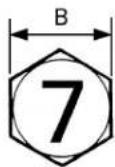
Scale
1BDABARAP006A



0 10 20 30 40 50 60 70(mm)
STORAGE

CAUTION
To avoid personal injury:
- Do not clean the machine with engine running.
● To avoid the danger of exhaust fume poisoning, do not operate the engine in a closed building without proper ventilation. - When storing, remove the key to avoid unauthorized persons from operating the machine and getting injured.
MACHINE STORAGE
If you intend to store your machine for an extended period of time, follow the procedures outlined below. These procedures will insure that the machine is ready to operate with minimum preparation when it is removed from storage,
- Check for loose bolts and nuts, and tighten if necessary.
- Apply grease to machine areas where bare metal will rust also to pivot areas.
- Inflate the tires to a pressure a little higher than usual.
- Change the engine oil and run the engine to circulate oil throughout the engine block and internal moving parts for about 5 minutes.
- With all implements lowered to the ground, coat any exposed hydraulic cylinder piston rods with grease.
- Remove the battery from the machine. When disconnecting the cables from the battery, start with the negative terminal first. When connecting the cables to the battery, start with the positive terminal first.
- Keep the machine in a dry place where the machine is sheltered from rain. Cover the machine.
- Store the machine indoors in a dry area that is protected from sunlight and excessive heat. If the machine must be stored outdoors, cover it with a waterproof tarpaulin.
- Jack the machine up and place blocks under the front and rear axles so that all 4 tires are off the ground. Keep the tires out of direct sunlight and extreme heat.
IMPORTANT :
- When washing the machine, be sure to stop the engine. Allow sufficient time for the engine to cool before washing.
- Cover the machine after the muffler and the engine have cooled down.
REMOVING THE MACHINE FROM STORAGE
- Check the tire air pressure and inflate the tires if they are low.
- Jack the machine up and remove the support blocks.
- Install the battery. Before installing the battery, make sure it is fully charged.
- Check all fluid levels (engine oil, transmission/hydraulic oil and any attached implements).
- Check all control levers and the brake for proper function free up or lubricate as necessary.
- Start the engine. Observe all gauges. If all gauges are functioning properly and reading normal, move the machine outside.
- Once outside, park the machine securely set the parking brake, place the control levers in the neutral lock position and let the engine idle for at least five minutes.
- Shut the engine off and walk around machine and make a visual inspection looking for evidence of oil leaks.
- With the engine fully warmed up, release the parking brake and test the brakes for proper adjustment as you move forward. Adjust the brakes as necessary.
Fuel

CAUTION
To avoid personal injury:
● Make sure the engine and muffler are sufficiently cooled down before trying to drain the fuel; otherwise there is a danger of causing a fire.
IMPORTANT :
- Do not leave the fuel (gasoline) in the fuel tank or carburetor for more than a month; otherwise the fuel might deteriorate to make it difficult to start the engine or cause the malfunction of the engine.
NOTE :
- If the engine is not to be used for more than a month, drain the fuel from the fuel tank and carburetor.
Before the off-season, drain the fuel from the fuel tank, carburetor and fuel filter bowl in the following manner.
[Draining the carburetor]
- Put an oil receiving pan under the drain port.
- Turn the carburetor fuel valve to the "DRAIN" position to drain the fuel from the carburetor.
- Drain the gasoline from the fuel filter bowl. Clean the inside of the fuel filter bowl as necessary.
-
Reinstall the fuel filter bowl.
-
After that, turn the carburetor fuel valve to the "STOP" (CLOSE) position.
NOTE :
● Before adding fuel, make sure the carburetor fuel valve is in the "STOP" (CLOSE) position. Turn the carburetor fuel valve to the "RUN" (OPEN) position before starting the engine.

(1) Carburetor fuel valve

(1) Carburetor fuel valve
(2) Drain port
(3) Fuel filter bowl
(A) "STOP" (CLOSE)
(B) "RUN" (OPEN)
(C) "DRAIN"
■Inspecting and Cleaning Fuel Filter Bowl
Clean the fuel filter bowl before adding fuel to the engine.

WARNING
To avoid serious injury or death:
● Never smoke nor use fire or naked flame during inspection or cleaning.
IMPORTANT :
- Mixing of foreign matter or water in the fuel might cause a plugged filter element prematurely or cause much water to accumulate on the bottom of the fuel filter bowl.
- If water accumulates on the bottom of the fuel filter bowl, clean the fuel filter bowl or replace it with a new one.
◆Inspecting and cleaning
- Turn the carburetor fuel valve from the "RUN" (OPEN) position to the "STOP" (CLOSE) position.

(1) Carburetor fuel valve
(2) Ring screw
(3) Fuel filter bowl
(A) "STOP" (CLOSE)
(B) "RUN" (OPEN)
(C) "DRAIN"
-
Loosen the ring screw and remove the fuel filter bowl.
-
Remove the filter element and wash it lightly by dipping in gasoline. Replace any excessively contaminated element with a new one.

1BDABDNAP077A
(1) Carburetor fuel valve
(2) Element
(3) Packing
(4) Fuel filter bowl
(5) Ring screw
IMPORTANT :
- Use caution not to damage or lose the element or packing.
-
Replace any element that shows an excessive plugging with a new one.
-
Reinstall the packing and element, using caution not to contaminate them.
IMPORTANT :
● Mixing of dirt or foreign matter in the fuel might cause the malfunction of the engine.
TROUBLESHOOTING
ENGINE TROUBLESHOOTING
If something is wrong with the engine, refer to the table below for the cause and its corrective measure.
| Symptom (If) Cause Remedy | ||
| Engine is difficult to start or will not start. | ● No operator on the seat. | ● Sit on the operator's seat. |
| ● Parking brake pedal not in the proper position. | ● Apply the parking brake. | |
| ● PTO lever not in the proper position. | ● Make sure PTO lever is in "DISENGAGED" (OFF) position. | |
| ● Motion control levers not in the proper position. | ● Make sure motion control levers are in "NEUTRAL LOCK" position. | |
| ● Key switch is not in the proper position. | ● Make sure key switch is in "ON" position. | |
| ● Carburetor fuel drain valve in the "STOP" (CLOSE) position. | ● Open the carburetor fuel valve. "RUN" (OPEN) position. | |
| ● No fuel. ● Replenish fuel. | ||
| ● Improper or stale fuel. (Fuel quality is poor.) | ● Replace fuel and the fuel filter. | |
| ● Water or dirt in the fuel system. | ● Replace fuel and see your Kubota dealer. | |
| ● Fuel hose or fuel filter clogged or damaged. | ● Clean or replace fuel lines, and see your Kubota dealer. | |
| ● Air cleaner is clogged. | ● Clean or replace the air cleaner. | |
| ● Spark plug damaged. | ● Adjust the spark plug gap or replace the spark plug. | |
| ● Check the spark plug wire connection. | ||
| ● Fuse is blown. ● Replace the fuse. | ||
| ● Engine oil viscosity is wrong. | ● Use oils of different viscosities, depending on ambient temperature. | |
| ● Battery becomes weak and the engine does not turn over quick enough. | ● Clean battery cables and terminals. | |
| ● Charge the battery. | ||
| ● In cold weather, always remove the battery from the engine, charge and store it indoors. Install it on the machine only when the machine is going to be used. | ||
| ● Over choking or choke is adjusted incorrectly. | ● Check and see your Kubota dealer. | |
| Insufficient engine power. | ● Insufficient or dirty fuel. | ● Check the fuel system. |
| ● Fuel filter is clogged. | ● Replace the fuel filter. | |
| ● Air cleaner is clogged. | ● Clean or replace the air cleaner. | |
| ● Spark plug damaged. | ● Adjust the spark plug gap or replace it. | |
| Symptom (If) | Cause | Remedy |
| Engine stops suddenly. | ● Insufficient fuel. | ● Refuel.● Check the fuel valve position.● Check the carburetor fuel valve position. |
| Rough engine running. | ● Spark plug damaged. | ● Adjust the spark plug gap or replace it. |
| ● High tension cord damaged. ● See your Kubota dealer. | ||
| ● Carburetion problems. ● See your Kubota dealer. | ||
| ● Ignition coil damaged. ● See your Kubota dealer. | ||
| ● Choke is adjusted incorrectly. | ● See your Kubota dealer. | |
| ● Fuel hose or fuel filter clogged or damaged. | ● Clean or replace fuel lines, and see your Kubota dealer. | |
| ● Improper or stale fuel.(Fuel quality is poor.) | ● Replace fuel and the fuel filter. | |
| ● Air cleaner is clogged. | ● Clean or replace the air cleaner. | |
| Exhaust fumes are colored.(Black, Dark or Gray) | ● Overload. ● Reduce load. | |
| ● Low grade fuel is used. ● Use specified fuel. | ||
| ● Fuel filter is clogged. ● Replace the fuel filter. | ||
| ● Air cleaner is clogged. | ● Clean or replace the air cleaner element. | |
| ● Choke is not fully opened. | ● Check the choke knob position. | |
| Exhaust fumes are colored.(White or Blue) | ● Excessive engine oil. | ● Reduce to the specified oil level. |
| ● Piston ring is worn or stuck. | ● See your Kubota dealer. | |
| Engine overheats. | ● Engine is overloaded. | ● Lower speed or reduce load. |
| ● Engine oil is insufficient. | ● Replenish engine oil. | |
| ● Engine air intake screen and cooling fins are dirty. | ● Clean the air intake screen and cooling fins. | |
| ● Air cleaner element is plugged. | ● Clean or replace the air cleaner element. | |
| ● Engine speed is too low. | ● Operate at the "FAST" speed. | |
| ● Operating ground speed is too fast. | ● Operate the machine at the slower ground speed. | |
| Engine knocks. | ● Stale or low octane fuel. | ● Use specified fuel. |
| ● Engine overloaded. | ● Lower ground speed or reduce load. | |
| ● Engine speed is too low. | ● Operate at the "FAST" speed. | |
| Engine will not idle. | ● Spark plug damaged. | ● Adjust the spark plug gap or replace it. |
| ● Faulty spark plug. | ● Replace the spark plug. | |
| ● Carburetion problem. | ● See your Kubota dealer. | |
If you have any questions, contact your local KUBOTA Dealer.
BATTERY TROUBLESHOOTING
| Symptom (If) Cause | Remedy Preventive measure | ||
| Starter does not function. | ●Battery overused until lights are dim. | ●Charge battery sufficiently. | ●Charge the battery properly. |
| ●Battery has not been recharged. | |||
| ●Poor terminal connection. | ●Clean the terminal and tighten securely. | ●Keep the terminal clean and tight.Apply grease and treat with anti-corrosives. | |
| ●Battery life expired. ●Renew battery. | |||
| From beginning starter does not function, and lights soon become dim. | ●Insufficient charging. ●Charge battery sufficiently. | ●Battery must be serviced properly before initial use. | |
| When viewed from top, the top of plates look whitish. | ●Battery was used with an insufficient amount of electrolyte. | ●Add distilled water and charge the battery. | ●Regularly check the electrolyte level. |
| ●Battery was used too much without recharging. | ●Charge battery sufficiently. | ●Charge the battery properly. | |
| Recharging is impossible. | ●Battery life expired. ●Replace battery. | ||
| Terminals are severely corroded and heat up. | ●Poor terminal connection. | ●Clean the terminal and tighten securely. | ●Keep the terminal clean and tight.Apply grease and treat with anti-corrosives. |
| Battery electrolyte level drops rapidly. | ●There is a crack or pin holes in the electrolytic cells. | ●Replace battery. | |
| ●Charging system trouble. | ●Contact your local KUBOTA Dealer. | ||
If you have any questions, contact your local KUBOTA Dealer.
MACHINE TROUBLESHOOTING
| Symptom (If) Cause Remedy | ||
| Machine operation is not smooth. | ● Hydrostatic transmission fluid is insufficient. | ● Replenish oil. |
| ● Filter is clogged. ● Replace the filter. | ||
| Machine dose not move while engine is running. | ● Parking brake is on. ● Release the parking brake. | |
| ● Transmission fluid level is insufficient. | ● Replenish oil. | |
| Machine moves when motion control levers are in "NEUTRAL LOCK" position.(Engine is operated.) | ● Hydrostatic lever linkage is not correctly adjusted. | ● Ask your dealer for hydrostatic lever linkage adjustment or pressure adjustment. |
| ● Control linkage pivots are sticking. | ● Full up and lubricate linkage. | |
If you have any questions, contact your local KUBOTA Dealer.
MOWER TROUBLESHOOTING
| Symptom (If) Cause | Remedy | |
| Blade does not rotate. ●PTO system is not normal: PTO system malfunctioning. | ● See your Kubota Dealer. | |
| ● PTO system is normal: Broken mower belt. | ||
| Mower belt slipping. | ● Weaken tension spring. | ● Replace. |
| ● Worn mower belt. ●Replace. | ||
| ● Mower plugged. ●Unplug and clean mower deck. | ||
| ● Debris in pulleys. ●Clean. | ||
| Discharge chute plugged. | ● Grass too wet. ●Wait for grass to dry. | |
| ● Grass too long. | ● Raise cutting height and cut grass twice. | |
| ● Cutting too low. ●Raise cutting height. | ||
| ● Engine rpm too low. ●Mow at full throttle. | ||
| ● Ground speed too fast. ●Slow down. | ||
| Streaking of grass uncut. | ● Ground speed too fast. | ● Slow down. |
| ● Engine rpm too low. | ● Mow at full throttle, check and reset engine rpm. | |
| ● Grass too long. ●Cut grass twice. | ||
| ● Blades dull or damaged. | ● Replace blades or have blades sharpened. | |
| ● Debris in mower deck. | ● Clean mower deck. | |
| Uneven cut. | ● Mower deck not level. | ● Level mower deck. |
| ● Ground speed too fast. ●Slow down. | ||
| ● Blades dull. | ● Have blades sharpened. | |
| ● Blades worn or damaged. | ● Replace blades. | |
| ● Low tire inflation. | ● Add air to correct pressure. | |
| ● Anti-scalp rollers not adjusted correctly. | ● Adjust anti-scalp rollers. | |
| ● Wheels pressure not adjusted correctly. | ● Set both tire pressure to the correct pressure.(See "TIRES" in "TIRES AND WHEELS" section.) | |
| Blades scalping grass. | ● Cutting height too low. | ● Raise cutting height. |
| ● Turning speed too fast. | ● Reduce speed on turns. | |
| ● Ridges in terrain. | ● Change mowing pattern. | |
| ● Rough or uneven terrain. | ● Adjust wheels pressure and anti-scalp rollers. | |
| ● Anti-scalp rollers not adjusted correctly. | ● Adjust wheels pressure and anti-scalp rollers. | |
| ● Bend blade(s). | ● Replace blade(s). | |
| Excessive vibration. | ● Debris on mower deck or in pulleys. | ● Clean mower deck and pulleys. |
| ● Damaged mower belt. ●Replace mower belt. | ||
| ● Damaged pulleys. ●Replace pulleys. | ||
| ● Pulleys out of alignment. ●Check pulleys. | ||
| ● Blades out of balance. ●Have blades balanced. | ||
| Mower loads down machine. | ● Engine rpm too low. | ● Mow at full throttle, check and reset engine rpm. |
| ● Ground speed too fast. ● Slow down. | ||
| ● Debris wrapped around mower spindles. ● | Clean mower. | |
| ● Front of deck too low. ●Adjust mower deck. | (See "MOWER DECK LEVEL" in "ADJUSTMENT" section.) | |
If you have any questions, contact your local KUBOTA Dealer.
ENGINE EMISSION RELATED INFORMATION
◆ The KGZ770-MA2, KGZ770-MA3 engine conforms to U.S. EPA and California emission regulations for off-road large or small SI engines.
● Emission compliance period: 1000 HOURS
● CARB emissions durability period: EXTENDED
◆Carburetor (KGZ770-MA2, KGZ770-MA3)
The carburetor is tamper resistant; the idle mixture screw has been covered by tamper plug after adjustment at the factory.
You CANNOT adjust this screw.
◆High altitude operation
IMPORTANT :
- Altitude compensation kit is applied for EPA and CARB certified engines only.
EPA and CARB emission regulations require the ultimate users of non-road SI engine, as their obligation, to adjust the emissions by installing the appropriate genuine altitude compensation kit. And the engine manufacturer must provide such kit when the engine is operated at an altitude that exceeds the standard level, as guaranteed by the engine manufacturer. For this purpose, KUBOTA prepared genuine altitude compensation kit described below. The ultimate users of SI engines must comply with the regulations through the installation of the appropriate altitude compensation kit for the altitude range where the engine will be operated.
| Altitude Compensation Kit | Applicable Altitude Ranges |
| Original carburetor (with 0 m kit)* |  0 to 1000 m(0 to 3300 ft) 0 to 1000 m(0 to 3300 ft) |
| 1500 m compensation carburetor kit |  500 to 2500 m(1600 to 8200 ft) 500 to 2500 m(1600 to 8200 ft) |
1BDABDMAP010A
*) If you have lost the original carburetor, buy the 0 m kit.
Altitude compensation kit part number: consult your local KUBOTA dealer and specify your engine type and engine serial No.
Consult your local KUBOTA dealer for further information on the altitude compensation kit.
Consult your local KUBOTA dealer for further information on this procedure.
INDEX
Adjustment of Foldable ROPS .....20
Air Cleaner Primary Element....53
Air Cleaner Primary Element and Secondary
Element 68
Air Intake Screen and Air Intake Area to
Prevent Overheating ....44
Amount of Fuel and Refueling....43
ANTI-SCALP ROLLERS 76
Battery Condition....60
Blade 71
Carbon Canister Air Filter....62
Carbon Canister Air Filter....70
Combustion Chamber 68
CREEP SPEED....75
Easy Checker (TM) 14
Engine Break-in....18
Engine Breather Hose 70
Engine Oil....52
Engine Oil Cooler Fins 55
Engine Oil Filter....64
Engine Oil Level 43
Engine Shroud....66
Engine Shroud Panel 53
Engine Start System....47
Engine Stop (By manual) 17
Engine Valve Clearance....68
Front side: 41
Fuel 82
Fuel Filter 56
Fuel Filter 68
Fuel Filter Bowl....57
Fuel Gauge....14
Fuel Lines....69
Fuel Lines....70
Fuel Pump 14
Fuel System 73
Fuses....70
Gear Box Oil....62
Gear Box Oil Level 49
Greasing....50
Hood....39
Hour Meter 15
HST NEUTRAL 74
Hydraulic Hose 69
Hydraulic Hose 70
Hydraulic Lift Control Pedal....21
Immediately Stop the Engine if:....14
Inflation Pressure 32
Inflation Pressure.... 45
Inspecting and Fuel Filter Bowl 83
Intake Air Line.... 69
Intake Air Line.... 70
Key Switch.... 13
LEVEL MOWER DECK (Front-to-Rear) ..... 78
LEVEL MOWER DECK (Side-to-Side) ..... 77
Lubricating All Grease Fittings.... 46
Lubricating Oil for New Machines.... 18
Machine Break-in.... 18
MAXIMUM SPEED (FORWARD) 75
Motion Control Lever 23
MOTION CONTROL LEVER ALIGNMENT ... 75
Motion Control Lever Pivot 66
Movable Parts.... 47
Mower Belt....73
Mower Gear Box Oil Seal 70
Mower Gear Box Oil-Seal.... 70
Oiling 52
OPC System.... 48
Operator's Seat.... 21
Parking Brake 58
Parking Brake Pedal.... 22
PTO Lever 31
Rear side: 42
Remove and Install Front Caster Wheels..... 33
Seat Belt 21
Spark Plug Condition & Gap.... 64
Starting 31
Step 39
Throttle Cable 61
Throttle Lever 22
Throttle Lever and Choke Knob.... 13
Tire Pressure 45
To Fold the ROPS 19
To Raise the ROPS to Upright Position...... 20
Transmission Fluid and Rear Axle Gear Case Oil (RH and LH) 66
Transmission Fluid Level 46
Transmission Oil Filter Cartridge 65
Transmission Strainer.... 68
Warm-up and Transmission Oil in the Low Temperature Range 15
- OPERATOR'S MANUAL
- KUBOTA
- ZERO TURN MOWER
- MANUAL DEL OPERADOR
- KUBOTA Corporation is …
- KUBOTA Corporation es ...
- ABBREVIATION LIST
- WARNING
- IMPORTANT
- UNIVERSAL SYMBOLS
- FOREWORD
- SAFETY FIRST
- CONTENTS
- SAFE OPERATION
- BEFORE OPERATING
- SAFE OPERATION-2
- OPERATING
- Starting
- ◆Working
- ◆Children
- ◆Operators, age 60 years and above
- ◆Operation on slopes
- DO
- DO NOT
- ◆Stopping
- USING THE PTO
- USING THE LIFT LINK
- TRANSPORTING
- SAFE OPERATION-4
- SERVICING AND STORAGE
- Servicing
- ◆Storage
- DANGER, WARNING AND CAUTION LABELS
- DANGER / POISON
- SAFE OPERATION-10
- CARE OF DANGER, WARNING, AND CAUTION LABELS
- SERVICING OF MACHINE
- SPECIFICATIONS
- NOTE:
- IMPLEMENT LIMITATIONS
- IMPLEMENT LIMITATIONS
- INSTRUMENT PANEL AND CONTROLS
- ILLUSTRATED CONTENTS ILLUSTRATED CONTENTS
- MOWER MOUNTING
- MOUNTING THE MOWER DECK
- CAUTION
- IMPORTANT :
- NOTE :
- ADJUSTING THE MOWER
- DISMOUNTING THE MOWER DECK
- MOUNT AND DISMOUNT MACHINE SAFELY
- STARTING THE ENGINE
- Make sure that the PTO lever is in the "DISENGAGED" (OFF) position.
- Place the motion control levers in the "NEUTRAL LOCK" position.
- Release the hydraulic lift control pedal to the "DOWN" position.
- Set the throttle lever as follows.
- Insert the key into the key switch. Turn the key switch to the "START" position and release the key to the "ON" position when the engine starts.
- ■Throttle Lever and Choke Knob
- [For a Cold Engine]
- [For a Warm Engine]
- ■Key Switch
- CHECK DURING OPERATING
- ■Immediately Stop the Engine if:
- ■ Easy Checker (TM)
- ■Fuel Gauge
- Fuel Pump
- ■Hour Meter
- COLD WEATHER STARTING
- WARMING UP
- ■Warm-up and Transmission Oil in the Low Temperature Range
- JUMP STARTING
- STOPPING THE ENGINE
- ■Engine Stop (By manual)
- ■Changing Lubricating Oil for New Machines
- ■Engine Break-in
- ■Machine Break-in
- DANGER
- OPERATING FOLDABLE ROPS
- ■To Fold the ROPS
- ■To Raise the ROPS to Upright Position
- ■Adjustment of Foldable ROPS
- Adjust the operator's position and engage the seat belt.
- Operator's Seat
- Seat Belt
- Raise the implement.
- ■Hydraulic Lift Control Pedal
- Accelerate the engine.
- Throttle Lever
- Unlock the parking brake.
- ■Parking Brake Pedal
- To release the parking brake:
- Operate the machine.
- ■Motion Control Lever
- Stop position
- Operating position
- Neutral position
- ◆Creep position (Moves the machine slowly forward)
- ◆Forward and Reverse Motion:
- To move reverse:
- To stop:
- ◆Re-start on the slopes
- How to re-start on the slopes:
- FORWARD:
- REVERSE:
- GENERAL LEFT TURN:
- GENERAL RIGHT TURN:
- SHARP (ZERO) RIGHT TURN:
- WORK LIGHT (OPTIONAL KIT)
- STOPPING
- PARKING
- TO LOCK:
- TO UNLOCK:
- TRANSPORTING
- OPERATING THE MOWER
- MAKING THE MOST OF YOUR MOWER
- ADJUSTING CUTTING HEIGHT
- : "UNLOCK"
- Reference
- OPERATING MOWER
- ■PTO Lever
- ■ Starting
- TIRES AND WHEELS
- TIRES
- Inflation Pressure
- WHEELS
- ■Remove and Install Front Caster Wheels
- ◆Removing
- Installing
- MAINTENANCE
- SERVICE INTERVALS
- PERIODIC SERVICE CHART LABEL
- Part No. K3272-6551-6 (ENGLISH) (2) Part No. K3272-6552-6 (SPANISH)
- ◆Engine Oil:
- ◆Transmission oil:
- ◆Fuel:
- PERIODIC SERVICE
- HOW TO OPEN THE HOOD AND STEP
- Hood
- Step
- HOW TO RAISE THE OPERATOR'S SEAT
- HOW TO OPEN THE LEVER GUIDE
- LIFT-UP POINT
- ■Front side:
- ■Rear side:
- DAILY CHECK
- ■ Checking Engine Oil Level
- ■ Checking Amount of Fuel and Refueling
- [Use of alcohol mixed gasoline (Gasohol)]
- ■ Checking and Cleaning Air Intake Screen and Air Intake Area to Prevent Overheating
- ■ Checking Tire Pressure
- ■Checking Transmission Fluid Level
- ■Lubricating All Grease Fittings
- ■ Checking Movable Parts
- EVERY 50 HOURS
- ■ Checking Engine Start System
- Test 1 (OPERATOR NOT ON THE SEAT)
- Test 2 (OPERATOR ON THE SEAT)
- Test 3 (OPERATOR ON THE SEAT)
- Test 4 (OPERATOR ON THE SEAT)
- Test 5 (OPERATOR ON THE SEAT)
- ■ Checking OPC System
- Test 1 (OPERATOR ON THE SEAT)
- ■ Checking Gear Box Oil Level
- Greasing
- EVERY 100 HOURS
- ■Changing Engine Oil
- ■Cleaning Air Cleaner Primary Element
- ◆Evacuator Valve
- ■Cleaning Engine Shroud Panel
- ■Cleaning Engine Oil Cooler Fins
- [ZG227 only]
- ■ Checking Fuel Filter
- ■Cleaning Fuel Filter Bowl
- ◆Cleaning
- ■Adjusting Parking Brake
- Check brake spring
- ◆Adjustment of brake spring length
- ◆Adjustment of brake spring play
- Check on the slope
- ■Battery Condition
- ◆Battery Charging
- ■Adjusting Throttle Cable
- ■Checking Carbon Canister Air Filter
- EVERY 150 HOURS
- ■Changing Gear Box Oil
- EVERY 200 HOURS
- ■Replacing Engine Oil Filter
- ■Checking Spark Plug Condition & Gap
- ■Replacing Transmission Oil Filter Cartridge
- ■Adjusting the Motion Control Lever Pivot
- ■Cleaning Engine Shroud
- EVERY 400 HOURS
- ■Changing Transmission Fluid and Rear Axle Gear Case Oil (RH and LH)
- ■Cleaning Transmission Strainer
- ■Replacing Fuel Filter
- EVERY 500 HOURS
- ■Adjusting Engine Valve Clearance
- EVERY AFTER 1000 HOURS
- ■Cleaning Combustion Chamber
- EVERY 1000 HOURS or EVERY 1 YEAR
- ■Replacing Air Cleaner Primary Element and Secondary Element
- [How to remove the secondary element]
- EVERY 1 YEAR
- ■ Checking Fuel Lines
- ■ Checking Hydraulic Hose
- ■ Checking Intake Air Line
- ■ Checking Engine Breather Hose
- ■ Checking Mower Gear Box Oil Seal
- EVERY 2 YEARS
- ■Replacing Carbon Canister Air Filter
- EVERY 4 YEARS
- ■Replacing Hydraulic Hose
- ■Replacing Fuel Lines
- ■Replacing Engine Breather Hose
- ■Replacing Mower Gear Box Oil-Seal
- ■Replacing Intake Air Line
- SERVICE AS REQUIRED
- ■Replacing Fuses
- ■ Checking and Replacing Blade
- ◆Checking
- ◆Replacing
- [RCK48P, RCK54P]
- [RCK60P]
- ■Replacing Mower Belt
- ■Bleeding Fuel System
- ◆Bleeding procedure is as follows:
- ADJUSTMENT
- ■HST NEUTRAL
- CREEP SPEED
- ■MAXIMUM SPEED (FORWARD)
- ◆Check the alignment
- ◆Aligning the control levers
- Lever position (High or Low)
- Lever alignment (Right and Left)
- MOWER DECK LEVEL
- ANTI-SCALP ROLLERS
- Front side anti-scalp roller
- Rear side anti-scalp roller
- ■LEVEL MOWER DECK (Side-to-Side)
- ◆Checking level (Side-to-Side)
- ◆Adjusting level (Side-to-Side)
- ■LEVEL MOWER DECK (Front-to-Rear)
- ◆ Checking level (Front-to-Rear)
- ◆Adjusting level (Front-to-Rear)
- STORAGE
- MACHINE STORAGE
- REMOVING THE MACHINE FROM STORAGE
- Fuel
- [Draining the carburetor]
- ■Inspecting and Cleaning Fuel Filter Bowl
- ◆Inspecting and cleaning
- TROUBLESHOOTING
- ENGINE TROUBLESHOOTING
- ENGINE EMISSION RELATED INFORMATION
- INDEX
Brand : KUBOTA
Model : ZG227LA-60
Category : Lawn mower