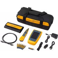
LinkIQ - Computer and peripheral cables FLUKE - Free user manual and instructions
Find the device manual for free LinkIQ FLUKE in PDF.


| Product Type | Cable and Network Tester |
| Brand | Fluke |
| Model | LinkIQ |
| Category | Computer and Peripheral Cables |
| Dimensions (approx.) | 8.66 x 4.33 x 2.36 inches (220 x 110 x 60 mm) |
| Weight (approx.) | 1.1 kg (2.4 lb) |
| Power Supply | Rechargeable Li-ion battery (7.2 V, 3400 mAh) |
| Battery Life | Up to 8 hours continuous use |
| Display | Color touchscreen (800 x 480 pixels) |
| Supported Cable Types | Twisted pair (Cat 3 / 5e / 6 / 6A / 7 / 7A), coaxial, fiber (with optional adapter) |
| Main Functions | Cable qualification, length measurement, wiremap, fault location, TDR, PoE detection, network connectivity test, tone generation |
| Frequency Range | 1 MHz to 300 MHz (twisted pair) |
| Length Measurement Accuracy | ± (3% + 0.5 m) for NVP > 70% |
| PoE Test | IEEE 802.3af/at/bt (up to 90 W) |
| Interfaces | RJ45, USB-C (for data transfer and charging), Wi-Fi (802.11 b/g/n) |
| Memory | Internal storage for up to 1000 test results |
| Languages | English, French, German, Spanish, Italian, Portuguese, Chinese, Japanese, etc. |
| Maintenance and Cleaning | Wipe with a soft, dry cloth; do not use solvents or abrasive cleaners |
| Safety | Complies with IEC 61010-1, CAT II 300 V, double insulation |
| Spare Parts and Repairability | Battery pack, test leads, remote adapter available as accessories; repair by Fluke authorized service centers |
| Warranty | 3 years (standard); extended options available |
Frequently Asked Questions - LinkIQ FLUKE
User questions about LinkIQ FLUKE
0 question about this device. Answer the ones you know or ask your own.
Ask a new question about this device
Download the instructions for your Computer and peripheral cables in PDF format for free! Find your manual LinkIQ - FLUKE and take your electronic device back in hand. On this page are published all the documents necessary for the use of your device. LinkIQ by FLUKE.
USER MANUAL LinkIQ FLUKE
Cable+Network Tester
Users Manual
LIMITED WARRANTY AND LIMITATION OF LIABILITY
Each Fluke product is warranted to be free from defects in material and workmanship under normal use and service. The warranty period is 1 year and begins on the date of shipment. Parts, product repairs, and services are warranted for 90 days. This warranty extends only to the original buyer or end-user customer of a Fluke authorized reseller, and does not apply to fuses, disposable batteries, or to any product which, in Fluke's opinion, has been misused, altered, neglected, contaminated, or damaged by accident or abnormal conditions of operation or handling. Fluke warrants that software will operate substantially in accordance with its functional specifications for 90 days and that it has been properly recorded on non-defective media. Fluke does not warrant that software will be error free or operate without interruption.
Fluke authorized resellers shall extend this warranty on new and unused products to end-user customers only but have no authority to extend a greater or different warranty on behalf of Fluke. Warranty support is available only if product is purchased through a Fluke authorized sales outlet or Buyer has paid the applicable international price. Fluke reserves the right to invoice Buyer for importation costs of repair/ replacement parts when product purchased in one country is submitted for repair in another country.
Fluke's warranty obligation is limited, at Fluke's option, to refund of the purchase price, free of charge repair, or replacement of a defective product which is returned to a Fluke authorized service center within the warranty period.
To obtain warranty service, contact your nearest Fluke authorized service center to obtain return authorization information, then send the product to that service center, with a description of the difficulty, postage and insurance prepaid (FOB Destination). Fluke assumes no risk for damage in transit. Following warranty repair, the product will be returned to Buyer, transportation prepaid (FOB Destination). If Fluke determines that failure was caused by neglect, misuse, contamination, alteration, accident, or abnormal condition of operation or handling, including overvoltage failures caused by use outside the product's specified rating, or normal wear and tear of mechanical components, Fluke will provide an estimate of repair costs and obtain authorization before commencing the work. Following repair, the product will be returned to the Buyer transportation prepaid and the Buyer will be billed for the repair and return transportation charges (FOB Shipping Point).
THIS WARRANTY IS BUYER'S SOLE AND EXCLUSIVE REMEDY AND IS IN LIEU OF ALL OTHER WARRANTIES, EXPRESS OR IMPLIED, INCLUDING BUT NOT LIMITED TO ANY IMPLIED WARRANTY OF MERCHANTABILITY OR FITNESS FOR A PARTICULAR PURPOSE. FLUKE SHALL NOT BE LIABLE FOR ANY SPECIAL, INDIRECT, INCIDENTAL OR CONSEQUENTIAL DAMAGES OR LOSSES, INCLUDING LOSS OF DATA, ARISING FROM ANY CAUSE OR THEORY.
Since some countries or states do not allow limitation of the term of an implied warranty, or exclusion or limitation of incidental or consequential damages, the limitations and exclusions of this warranty may not apply to every buyer. If any provision of this Warranty is held invalid or unenforceable by a court or other decision-maker of competent jurisdiction, such holding will not affect the validity or enforceability of any other provision.
Fluke Corporation
6920 Seaway Blvd
Everett, WA 98203
U.S.A.
Fluke Europe B.V.
P.O. Box 1186
5602 BD Eindhoven
The Netherlands
Table of Contents
Title Page
Introduction.... 1
Contact Fluke Corporation.... 1
Safety Information.... 2
Product Familiarization 2
Features.... 3
Parts 4
Controls and Connections.... 5
Hang Strap.... 6
Display 7
Main Menu 8
Menu Controls.... 8
Global Settings Menu 10
Configure a Static Address.... 12
Change the IP Address of the Product 12
Change the IP Address of a Device to Ping.... 13
Configure an IPv4 Address.... 14
Configure an IPv6 Address.... 15
Copper Tests Menu 16
Copper Tools Menu.... 16
Copper Settings Menu 17
Automatic Test Discovery.... 19
Before a Copper Test.... 19
Switch Tests 20
Switch Connectivity Tests.... 20
Ping Tests 20
Power over Ethernet (PoE) Tests 21
Do a Switch Test.... 21
Switch Test Results.... 22
Switch Test Detail Results 25
Ping Test Results.... 25
PoE Test Results 28
PoE Test Pass Example.... 31
PoE Test Fail Reasons 32
Cable Tests 33
Do a Cable Test.... 33
Cable Test Results.... 35
Wire Map Screen Multiple Failures.... 37
Open Pairs Failure 38
Short Failure 39
Split Pairs Failure 39
Test Limit Failure.... 40
Wi-Fi Tests Menu.... 40
Wi-Fi Symbols 41
Wi-Fi Notes 42
Networks 42
Networks Screen 43
Network Details Screen.... 43
Wi-Fi Connection Test Screen 45
Channels Screen 46
Access Points 49
Access Points Screen....50
Access Point Details Screen Wi-Fi Test 51
Save a Test Result 51
Results Menu 51
Delete Test Results 53
Upload Results to LinkWare PC 54
Tests with MS-IE-Adapter Set.... 54
Maintenance.... 55
Clean the Product 55
Battery 55
Product Specifications 56
Introduction
The LinkIQ (LIQ-100)/LinkIQ Duo (LIQ-200 Duo) Cable+Network Tester (the Product or Tester) is a handheld test instrument for use in many applications to test twisted pair cables, network connectivity, Power over Ethernet (PoE), and to do Wi-Fi tests. These applications include system integration, cable installation, network and security system maintenance, and Wi-Fi discovery and connected tests. For copper tests, the Product provides an automatic test discovery suite that recognizes a connected device and automatically selects the appropriate type of test for the device. See Automatic Test Discovery.
The Product shows images on an LCD touch screen and saves data to internal memory which can be transferred to a PC through a direct USB connection to the PC.
The Product includes LinkWare™ PC desktop software. LinkWare PC software is a high-performance, professional software suite for quality analysis and reporting. For more information or to download the software, go to the LinkWare PC website.
The Product is compatible with the MicroScanner™ PoE Remote Identifier and the IntelliTone™ Pro Toner, Tracer, and Probe.
Contact Fluke Corporation
Fluke Corporation operates worldwide. For local contact information, go to our website: www.flukenetworks.com.
To register your product, or to view, print, or download the latest manual or manual supplement, go to our website.
+1-425-446-5500 info@flukenetworks.com
Safety Information
General Safety Information is in the printed Safety Information document that ships with the Product and at www.flukenetworks.com. More specific safety information is listed where applicable.
A Warning identifies hazardous conditions and procedures that are dangerous to the user. A Caution identifies conditions and procedures that can cause damage to the Product or the equipment under test.
Note
Before you use the Product for the first time, charge the battery for a minimum of 1.5 hours. See Battery.
Caution
To activate the input protection circuitry of the Product, turn on the Product before you connect a cable to the Product. To turn on the Product, push ① .
Product Familiarization
The manual explains features for multiple models. Because models have different features, not all of the information in the manual may apply to your model. Use Table 1 to identify the features of your model.
Features
Table 1 is a list of the features of the Product.
Table 1. Features
| Feature LinkIQ LinkIQ Duo | ||
| Copper Tests | ||
| Auto test a switch or cable ● ● | ||
| Switch tests | ||
| Switch connectivity ● ● | ||
| Ping ● ● | ||
| Power over Ethernet (PoE) ● ● | ||
| Cable tests | ||
| Cable length ● ● | ||
| Cable qualification ● ● | ||
| Cable wire map ● ● | ||
| Wi-Fi Tests | ||
| Network ● | ||
| Channel ● | ||
| Access Point | ● | |
Parts
Table 2 shows the parts that may ship with the Product.
Table 2 Parts
| 1 2 3 4 5 6 7 8 | |||
| Item Description Item Description | |||
| ① | The Product | ⑤ | Remote ID 1 [2] |
| ② | Battery charger | ⑥ | Office locator holder |
| ③ | Universal power adapter kit[1] | ⑦ | USB C to USB A cable |
| ④ | Hang strap | ⑧ | CAT6A Copper patch cable |
| [1] Not available in all kits. [2] The Product can work with Remote ID 2 to Remote ID 7 (available separately as REMOTE-ID KIT or included with LIQ-KIT) | |||
Controls and Connections
Table 3 shows the controls and connections of the Product.
Table 3. Controls and Connections

| Item Description Item Description | |||
| 1 | RJ-45 jack | 4 | LCD touch screen (display) |
| 2 | Hang strap attachment slots | 5 | Power button. |
| 3 | Use the USB C terminal to charge the battery or upload results to LinkWare PC. The Product cannot do a test while the battery charges or while results upload to LinkWare PC. | ||
Hang Strap
Figure 1 shows how to attach the hang strap.
Figure 1. Hang Strap Attachment

Display
When you turn on the Product for the first time, the language selection screen shows on the display. If needed, scroll to see more languages, tap a language, and tap OK to set the language to use in the user interface (UI).
The users manual shows English screens in examples and translates the explanations as appropriate in tables or text. Table 4 shows the items on the display.
Table 4. Display

| Item Description Item Description | |||
| 1 | Time | 4 | Main menu toolbar. See Main Menu. |
| 2 | Date | 5 | Copper Tests menu See Copper Tests Menu. |
| 3 | Battery status | 6 | Wi-Fi Tests menu See Wi-Fi Tests Menu. |
Main Menu
Table 5 is a list of the menus available in the Main Menu.
Table 5. Main Menu
| Menu Function | ||
 | Home Tap to go to the Home screen. | |
| [BOAA] | Results | Tap to view or manage results. See Results Menu. |
 | Settings | Tap to set user preferences and view information about the Product. See Global Settings Menu. |
Menu Controls
To use the menus to change and view settings:
- Tap an icon on the main menu to open a submenu.
The foreground of the selected icon changes to white.
- Tap a menu control to set and change options. See Table 6.
Some menus contain a scroll bar on the right side to indicate there are additional options. The scroll bar is not a control. To view additional options, touch the display and slide the screen up or down. The scroll bar indicates the location in the menu.
- To close a submenu and return to the Home screen, tap

Table 6 is a list of the menu controls or features.
Table 6. Menu Controls or Features
| Control Function | |
| —— | When shown under a selection, indicates which of two options is selected. |
| 0.0 | Option selected. |
 | Turns on or off a feature. |
 | Feature is on or enabled. |
| Feature is off or disabled. | |
 | In a list, tap an option to set the selection. In the Results menu more than one item may be selected at a time. SeeResults Menu. |
 | Tap to open an option menu. |
 | Decreases a numerical value. |
 | Increases a numerical value. |
 | Return to the previous screen and, if necessary, save changes. |
 | Return to the previous screen without saving changes. |
 Save changes or do an action. Then, return to the previous screen. Save changes or do an action. Then, return to the previous screen. | |
C, L Do not do an action and return to the previous screen. L Do not do an action and return to the previous screen. | |
 | Tap to add a feature such as an IP address. |
 | Tap to delete a feature such as an IP address. |
 | Tap to delete text typed in a field. |
Global Settings Menu
Table 7 is a list of the options available in the Global Settings menu. The Product keeps the last saved settings when the Product turns off and back on.
Table 7. Global Settings Menu
| Option Menu Option Description | ||
| Auto Increment | Automatically increments the Test ID by one number or letter for the next test. Default setting. | |
| Use to manually increment or edit the Test ID. | ||
| NetworkPing | Tap to select:DHCPto automatically assign an IP address to the Product.Staticto configure the IP address, Subnet Mask, Gateway, and DNS of the Product. SeeChange the IP Address of the Product.The default settings are:IPv4 Address:DHCPIP, Gateway, andDNSaddresses: 0.0.0.0Subnet Mask: /24 (255.255.255.0)IPv6 Address:DHCP(which is SLAAC/DHCPv6 for IPv6)IP, Gateway, andDNSaddresses: ::0Subnet Mask: /64With the IP address of the Product automatically assigned or configured in the Network setting, tap to open the Ping screen to:Enable or disable the Ping feature. Enabled is the default setting.With Ping enabled, use to:Automatically do a Ping test after you do a network switch test. Default Setting: IPv4 address 8.8.8.8Use the saved protocol (IPv4 or IPv6) and enter a new target IP address that uses the same protocol.Delete an IPv4 target address to add and configure an IPv6 target address or vice versa.See Change the IP Address of a Device to Ping. | |
| CDP/LLDPTimeout | Tap to select the time in seconds to wait for a CDP/LLDP response before the Product retries network discovery. The default is 30 sec. | |
| Brightness |  | Adjusts the brightness of the display. Touch and slide the bar to the left to decrease the brightness or to the right to increase the brightness. |
| Auto Shutoff |   | The Product turns off after 15 minutes of no use. While the Product charges, Auto Shutoff is disabled. Default setting.The Product remains on until the battery needs to be charged again. |
| Option Menu Option | Description | |
| Sound |  | The Product emits an audible sound at the completion of a test. Default setting. |
 | The Product does not emit an audible sound at the completion of a test. | |
| Numbers -- Set the decimal point indicator. | ||
| Units -- Set or view the units to use in measurements. | ||
| Date/Time | Tap to select options to set the date, time, date format, and time format. | |
| Language Tap to select a language after initial setup. | ||
| About -- | Tap to view the radio certificates, serial number, Ethernet and Wi-Fi MAC addresses, and version information of the Product. | |
| Factory Reset -- | Tap to delete all test results and reset the Product to the factory default settings. | |
Configure a Static Address
Use this section to configure an IP address to use for the Product or to use on a device connected to a network.
Change the IP Address of the Product
To change the IP address of the Product:
- Tap

Network > IPv4 or IPv6 > Static.
With Static selected, the IP, Subnet Mask, Gateway, and DNS buttons show. With Static selected for both IPv4 and IPv6, a scroll bar also shows.
- Configure the address. See Configure an IPv4 Address or Configure an IPv6 Address.
Change the IP Address of a Device to Ping
Set up the Product to use either an IPv4 or an IPv6 address of a device to ping, but not both.
To set up a ping test:
- Turn on the Product.
-
Connect the Product to a network.
-
Go to > Ping.
-
If needed, set Ping to enable.
-
To change from an IPv4 address to another IPv4 address or from an IPv6 address to another IPv6 address, tap U on the IP button and enter the new address. See Configure an IPv4 Address or Configure an IPv6 Address.
-
To change from an IPv4 address to an IPv6 address or vice versa:
a. On the IP button, tap

b. Tap OK to delete the address.
c. Tap IPv4 or IPv6.
d. Tap + to add an IP address button.
e. On the IP button, tap U and enter a new address. See Configure an IPv4 Address or Configure an IPv6 Address.
Configure an IPv4 Address
To manually configure an address:
-
Tap IP to open the IP address screen.
-
Enter the IP address.
An IPv4 address is 32 bits represented in dot-decimal notation. The address consists of four groups of decimal digits (0 to 255) separated by a dot (period). The UI has a separate entry field for each group of digits.
Examples of valid IPv4 addresses:
• 8.8.8.8 (Google DNS servers)
• 192.168.10.1
• 10.10.10.1
Examples of invalid IPv4 addresses:
• 0.0.0.0
• 255.255.255.255
- An address with "0" as the first byte
- An address with a decimal number greater than 255
- 224.0.0.0 /4
• 127.0.0.0 /8
- Tap Subnet Mask, scroll if needed, and tap a subnet mask.
The Product shows subnet mask notation for example, 255.255.0.0. The corresponding prefix length values are /1 to /31.
- Tap Gateway to enter the Gateway address.
- Tap DNS to enter the DNS address.
Configure an IPv6 Address
To manually configure an address:
-
Tap IP to open the IP address screen.
-
Enter the IP address.
An IPv6 address is 128 bits represented as eight groups of four hexadecimal digits (16 bits) with a colon between each group. The UI has a separate entry field for each group of digits.
Examples of valid IPv6 addresses:
• 2001:4860:4860::8888 (Google DNS servers)
• 2001:0db8:0000:0000:8a2e:0000:0370:7334
Examples of invalid IPv6 addresses:
• 0:0:0:0:0:0:0:0
- ffff:ffff:ffff:ffff:ffff:ffff:ffff:ffff
- ff00::/8
- ::ffff:0:0 to ::ffff:ffff:ffff
Because IPv6 addresses can be long, there are valid ways to shorten them.
- Omit leading zeros within a group. In the second example of valid addresses above, the second and seventh groups may be shortened to db8 and 370, respectively.
- If two or more adjacent groups contain 0000, replace them with two colons as in the first example above.
- If a group contains 0000 and is not adjacent to another group that contains 0000, replace it with one zero.
According to the rules above, the full address of the first example is:
2001:4860:4860:0000:0000:0000:0000:8888, and the shortened address of the second address is 2001:db8::8a2e:0:370:7334.
- Tap Subnet Mask, scroll if needed, and tap a subnet mask.
Although the Product uses the term subnet mask, the prefix length from /1 to /127 shows.
-
Tap Gateway to enter the Gateway address.
-
Tap DNS to enter the DNS address.
Copper Tests Menu
Table 8 is a list of the menus available in the Copper Tests menu.
Table 8. Copper Tests Menu
| Menu Function | ||
 | Tools | Tap to access additional tools. The tools cannot be used while in a test. See Copper Tools Menu. |
 | Settings Use to set up a copper cable or switch test. | |
 | Auto Test | Tap to do a cable or switch test. The Product automatically selects the appropriate type of test for the connected device. See Automatic Test Discovery. |
 | Switch Tap to do a switch test. | |
 | Cable Tap to do a cable test. | |
Copper Tools Menu
Table 9 is a list of the options available in the Copper Tools Menu.
Table 9. Copper Tools Menu
| Options Menu Option Description | ||
| Toner | IntelliTone | The Product emits a digital tone that an IntelliToneTM probe can use to locate and isolate cables behind walls, at patch panels, or in bundles. |
| Analog Tone 1 | The Product emits an analog signal that a standard analog probe can use to identify cables in bundles. | |
| Analog Tone 2 | ||
| Analog Tone 3 | ||
| Blink Port Light -- | Tap to blink a port light on a hub or switch to verify connectivity and cable routes. | |
Copper Settings Menu
Table 10 is a list of the options available in the Copper Settings menu. The Product uses the last saved settings when the Product turns off and back on.
Table 10. Copper Settings Menu
| Option Menu Option Description | ||
| Wire map Settings | ||
| Shield Test |  | Uses the continuity of the shield on the cable to determine if a test passes. |
 | Even if a shield is connected to a cable, the continuity of the shield is not used to determine if a test passes. Default setting. | |
| Allow Crossover |  | The wire map of either a straight through cable or a crossover cable is used to determine if a test passes. |
 | The wire map of a straight through cable is used to determine if a test passes. A wire map of a crossover cable fails. Default setting. | |
| Pinout | Select to set the wire color configuration to use to do a test.T568Ais the default setting. | |
| Cable Settings | ||
| Test Limit | 10BASE-T | Verify if a cable with continuity on at least the 1,2 and 3,6 pairs can support 10BASE-T (10) data rate throughput. |
| 100BASE-TX | Verify if a cable with continuity on at least the 1,2 and 3,6 pairs can support 100BASE-TX (100) data rate throughput. | |
| 1000BASE-T | Verify if a 4-pair cable with continuity on all 4 pairs can support 1000BASE-T (1G) data rate throughput. | |
| 2.5GBASE-T | Verify if a 4-pair cable with continuity on all 4 pairs can support 2.5GBASE-T (2.5G) data rate throughput. | |
| 5GBASE-T | Verify if a 4-pair cable with continuity on all 4 pairs can support 5GBASE-T (5G) data rate throughput. | |
| 10GBASE-T | Verify if a 4-pair cable with continuity on all 4 pairs can support 10GBASE-T (10G) data rate throughput. Default setting. | |
| NVP | Set the Nominal Velocity of Propagation (NVP) value based on the cable. NVP value range is 50-99. The default NVP value is 68. | |
| PoE Test |  | Enable PoE detection. Use to automatically do a PoE test after you do a network switch test. Default setting. |
 | Disable PoE detection. Use to decrease the time to do a switch test. | |
Automatic Test Discovery
For copper tests, the automatic test discovery feature recognizes a connected device and automatically selects the appropriate type of test compatible with the device.
Automatic test discovery selects a:
- Cable test if:
- There is no cable connected to the Product.
There is a cable connected to the Product but not connected to a port on an external device. - The Product detects a Remote ID.
See Cable Tests.
- Switch test if the Product detects a network device. See Switch Tests.
- Switch test with Ping test with Ping enabled and the Product detects a network device. See Switch Tests.
- Switch test with Power over Ethernet (PoE) with PoE enabled and the Product detects a Power Sourcing Equipment (PSE) device. See Switch Tests.
Before a Copper Test
Read the warnings below before you do a switch or cable test.
Warning
To prevent possible electrical shock, fire, personal injury, or damage to the Product:
- To activate the input protection circuitry of the Product, turn on the Product before you connect a cable to the Product.
- During a test, do not connect a cable to the Product.
- During a test, do not disconnect a cable from the Product.
- The tester is not intended to be connected to active telephone inputs, systems, or equipment, including ISDN devices. Exposure to the voltages applied by these interfaces may damage the tester and create a potential shock hazard.
- Use caution when working in potentially hazardous locations such as an elevated location on a ladder or roof top, especially if work is occurring in proximity to a lightning storm. Also use caution if external communication cables are run at length in parallel to electrical power installation cables. These types of installations can expose communication cables to coupled electrical transients that could be accessible on exposed conductive parts of the equipment during operation. While in general these transients are not expected to be an electric shock hazard, startled reaction from these transients could lead to a secondary hazard such as loss of balance and lead to a fall or other injury. To reduce risk of exposure, limit contact to accessible conductive parts of I/O terminals during operation.
Switch Tests
The Product can do switch connectivity, Ping, and Power over Ethernet (PoE), and tests.
Switch Connectivity Tests
In a network test, the Product performs a series of queries to determine and report information about a switch or device. The Product determines information about the device and reports advertised data rates with full-duplex or half-duplex. See Switch Test Results.
Ping Tests
The Product supports IPv4 and IPv6 addresses. Both protocols may be configured based on what is available on the network.
With Ping enabled, the Product pings the device specified in Settings > Ping and the DNS servers and gateways that the Product detects. The Product pings each device four times with a 1 second threshold timeout for each attempt and shows:
- If an IP address is accessible.
- The round-trip response time in milliseconds (ms).
Power over Ethernet (PoE) Tests
With PoE Test enabled, the Product automatically does a PoE test after the completion of a network switch test.
Definitions:
- Power Sourcing Equipment (PSE) is a device, such as a switch, that can provide PoE.
- A Powered Device (PD) is a device that can receive PoE from a PSE.
- PoE negotiation standards are defined in IEEE 802.3af/at/bt.
In a PoE test:
- With the Product connected to a PSE, the Product acts as a PD and starts a hardware negotiation with the PSE.
- If the PSE is compliant with the IEEE 802.3 standard, the Product determines the maximum power the PSE can offer (Class 0 to Class 8).
- The Product places a load on the PSE to determine if the PSE delivers the power required to meet the negotiated hardware power class at the PD.
- If the PSE meets the hardware negotiation power class, the Product attempts a software negotiation with LLDP/CDP to determine the software power level offered.
- The Product places a load on the PSE to determine if the PSE delivers the software negotiated power at the PD.
Do a Switch Test
To do a switch test:
- Turn on the Product.
- Connect one end of the CAT6A copper patch cable or other approved cable into the RJ-45 jack on the Product. See Figure 2.
Figure 2. Switch Test Set Up
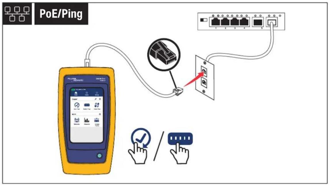
- Connect the other end of the patch cable into an RJ-45 jack in an outlet connected to a switch.
- If needed, adjust the settings. See Global Settings Menu and Copper Settings Menu.
- Tap √ or ⋯ to do a test.
The results show on the display.
- On a test result screen, tap SAVE AS.... See Save a Test Result.
Switch Test Results
Table 11 shows possible results of a switch test.
Table 11. Switch Test Results
 | |
| Item Description | |
| 1 | When the Product receives a compliant LLDP or CDP packet from a device, the summary button shows the:The number of the switch port that the device connects toThe switch nameThe IP addresses of the switch. A maximum of two IP addresses can show. Additional IP address may be listed on the details screen. The number in parentheses indicates how many IP addresses identify as available.Tap to view detailed results. SeeSwitch Test Detail Results.An unmanaged or non-compliant device may not report the details of the switch. |
| 2 | When connected to a network, the maximum speed that the Product connects to the switch shows. The maximum speed that the Product connects to the switch may be slower than the maximum advertised speed (3) of the switch. |
| Item Description | |
| 3 | Shows the advertised speeds of the device and whether they have full-duplex or half-duplex capability at the advertised speed.Speeds in black indicate the switch advertises that speed. Speeds in gray indicate the switch does not advertise that speed.Full DuplexA check mark (Y) indicates the device can send and receive communication simultaneously at the advertised speed.A dash (—) indicates the device does not have full-duplex capability at the advertised speed.Half DuplexA check mark (Y) indicates the device can send and receive communication but not simultaneously at the advertised speed.A dash (—) indicates the device does not have half-duplex capability at the advertised speed.A blank space indicates that half-duplex capability is not available at the advertised speed. |
| 4 | The ping summary button shows only when Ping is enabled.Z: Indicates the test passes.X: Indicates the test fails.The maximum round trip time in ms of the 4 ping attempts or -- ms if no ping attempts are successful.The IP address of the device on the network that is pinged.Tap to open the Ping screen to view detailed ping results. See Ping Test Results. |
| 5 | PoE results show only when PoE is on and the Product is connected to a PoE device. If needed, scroll down to see all the results. See PoE Test Results. |
Switch Test Detail Results
Table 12 shows possible detail results of a switch test. When an item is not configured with a name or description, -- shows.
Table 12. Switch Test Detail Results
| Name Description | |
| Switch Name The name of the nearest switch | |
| Switch Description The description of the nearest switch | |
| Port ID The port number of the switch that the Product is connected to | |
| Port Description The description of the port | |
| VLAN The VLAN that is configured on the switch port | |
| VLAN Name The name assigned to the VLAN | |
| IP Address A list of IP addresses reported by the switch | |
| MAC Address The MAC address of the switch | |
| Protocol | The discovery protocols used by the switch protocols show. There may be a combination of LLDP, CDPv1, or CDPv2. |
Ping Test Results
The Product pings a user-defined IP address, DNS server, and gateway 4 times.
With a successful test, the Product shows the IP address of each device and the response time in milliseconds (ms) from each ping shows in the results.
If a ping attempt fails, ✗ shows instead of a time value.
If one or more ping attempt fails, an error message shows with a description of the problem of the first ping attempt that fails.
Table 13 shows possible results of a ping test.
Table 13. Ping Test Results
| Item Description | |
| General section | |
| IP Address | The IP address configured in Settings > Ping, |
| Round Trip Times | The round trip time in ms from each time the Product pings the IP address. |
| Packets | Z shows if no packets are lost. ✗ shows if one or more packets is lost. |
| Lost | The number of lost packets. For example 1/4 indicates one packet is lost of the four packets sent. |
| Size | The size in bytes (typically 64 bytes) of the ping packet sent for each test. |
| Error information | If one or more packets is lost, an error message shows with a description of the problem of the first lost packet. |
| Network | The information that shows depends on the configuration of the network. If the Product detects only one protocol (IPv4 or IPv6) on a network, the information for that protocol shows. If the Product detects both protocols, the information for both protocols shows.Information for the DHCPv6 server shows only if the network uses DHCPv6. If the network uses SLAAC without DHCPv6, the DHCP server address, offer, ACK, and lease times do not show. |
| My IPv4 or My IPv6 | The address the Product receives from the DHCP server as an offer or the user-defined static address. |
| Subnet Mask The subnet mask of the network the Product connects to and tests on. | |
| DHCP Server The IP address of the DHCP server. | |
| Offer Time | For IPv4 addresses, this is the length of time between when the Product sends the discovery signal and receives an address offer from the DHCP server.For IPv6 addresses, the DHCPv6 advertised time shows. The advertised time is the time between when the Product sends the DHCPv6 solicit packet and receives the advertise response packet. |
| ACK Time | For IPv4 addresses, the length of time between when the Product sends the request and receives the acknowledgment from the DHCP server.For IPv6 addresses, the DHCPv6 reply time shows. The reply time is the length of time between when the Product sends the DHCPv6 request and receives the reply response packet. |
| Lease Time | For IPv4 addresses, the length of time the offered address is valid. Lease time shows in D (days), H (hours), and M (minutes).For IPv6 addresses, the DHCPv6 preferred-lifetime shows. The preferred-lifetime is a the length of time in seconds that an address is in the preferred state and can be used without restrictions. If the preferred-lifetime expires, the address becomes deprecated.NoteDeprecated addresses may be used for an existing communication. Do not use a deprecated address for new communications. |
| DNS | With the network configured to automatically detect DHCP, up to four DNS server results show. IPv4 results show before IPv6 server results.With the network configured statically, only one DNS server per protocol shows in the results with a maximum of two total results. For example, one IPv4 or one IPv6 result shows, or one of each protocol shows. |
| Gateway | This section shows when the Product detects the availability of a gateway or router.With the network configured to automatically detect DHCP, up to four gateway results show. IPv4 results show before IPv6 server results.With the network configured statically, only one gateway per protocol shows in the results with a maximum of two total results. For example, one IPv4 or one IPv6 result shows, or one of each protocol shows. |
PoE Test Results
Table 14 shows possible results of a PoE test.
Table 14. PoE Test Results
| 1 2 3 ✓ Single ✓ Dual A ✓ Dual B 1 2 3 6 4 5 7 8 HW Class: 6 51.0 W at PD ✓ 55.0 V Under Load, 42.5 V Minimum SW Negotiated Class: 8 ✓ 71.3 W at PD ✓ 54.2 V Under Load, 41.1 V Minimum | 1 2 3 ✓ Single ✓ Dual A ✓ Dual B 1 2 3 6 4 5 7 8 HW Class: 3 13.0 W at PD ✓ 0.0 V Under Load, 36.0 V Minimum SW Negotiated Class: - --- | |
| Item Function | ||
| ① | Tap to view single signature power results. Z: Indicates the switch can negotiate single signature power. ×: Indicates the switch cannot negotiate single signature power. | |
| ② | Tap to view Dual A signature power results. Z: Indicates the switch can negotiate dual signature power on pairs 1,2 and 3,6. —: Indicates the switch cannot negotiate dual signature power. | |
| ③ | Tap to view Dual B signature power results. Z: Indicates the switch can negotiate dual signature power on pairs 4,5 and 7,8. —: Indicates the switch cannot negotiate dual signature power. | |
Table 14. PoE Test Results (cont.)
| Item Function | |
| 4 | Shows which pairs have power. |
| 5 | The hardware negotiated power class (Class 0 to Class 8) of the PSE device. |
| 6 | The loaded power in watts provided by the PSE at the PD. |
| 7 | The minimum required volts the device needs to meet under load per the IEEE 802.3 standard based on the HW negotiated power class (5). |
| 8 | Measured voltage under load at reported power draw.Z: Indicates the voltage meets the requirements for the HW negotiated power class (5).X: Indicates the voltage does not meet the requirements for the HW negotiated power class (5).Or,The switch under test cannot deliver power to the device because the maximum power which the switch can deliver is already in use. |
| 9 | The software negotiated power class (Class 1 to Class 8) of the device.This section does not show information, If:The device does not support the voltage required to meet the HW negotiated power class.The device does not support software negotiation. |
| 10 | The loaded power in watts provided by the PSE at the PD. |
| 11 | The minimum required volts the device needs to meet under load per the IEEE 802.3 standard based on the SW negotiated power class (9). |
| 12 | Measured voltage under load at reported power draw.Z: Indicates the voltage meets the requirements for the SW negotiated power class (9).✗: Indicates the voltage does not meet the requirements for the SW negotiated power class (9).Or,The switch under test can deliver the HW negotiated power class, but the switch cannot deliver the additional power to the device required to meet the SW negotiated power class because the maximum power which the switch can deliver is already in use.—: Indicates the device does not support the voltage required to meet the HW negotiated power class. |
PoE Test Pass Example
Figure 3 shows an example of test results of a single signature PoE device that passes. See the explanation of the results below the figure.
Figure 3. PoE Test Pass Example
| HW Class: 651.0 W at PD |
| Z 55.0 V Under Load, 42.5 V Minimum |
| SW Negotiated Class: 871.3 W at PD |
| Z 54.2 V Under Load, 41.1 V Minimum |
The hardware class section passes because:
- The device identifies as a HW Class 6 capable of 51.0 W at PD.
- The Product applies a load to the device to validate if the available power from the PSE at the PD meets the standard of the negotiated class (in this example, a Class 6 device).
- The device delivers 55.0 V under the load which is ≥ 42.5 V, the minimum amount required for a device to meet the Class 6 standard.
The software class section passes because:
- The device identifies as a SW Negotiated Class 8 capable of 71.3 W at PD.
- The Product applies a load to the device to validate the available power from the PSE at the PD meets the standard of the negotiated class (in this example, a Class 8 device).
- The device delivers 54.2 V under the load which is ≥41.1 V, the minimum amount required for a device to meet the Class 8 standard.
PoE Test Fail Reasons
A PoE device fails a test if:
- The device identifies as capable of a negotiated hardware class greater than the power the device can deliver under the load required to meet the standard for the stated class.
- The device identifies as capable of a negotiated software class greater than the power the device can deliver under the load required to meet the standard for the stated class.
- The switch under test cannot deliver power to the device because the maximum power which the switch can deliver is already in use.
Cable Tests
In a twisted pair cable test, the Product performs a series of radio frequency (RF) tests to determine the transmission parameters of the cable. The parameters are compared to the test limits specified by IEEE 802.3 for Ethernet. Unlike transmission testers that pass bits across the cable, the Product evaluates the physical qualities of the cable.
• Measures length up to 304.8 m (1000 feet)
- Delay skew between pairs
- Transmission parameters used to qualify the cable:
○ Insertion loss ○ Delay skew
- Return loss
- Length
- NEXT
- Wire map
- Cable qualification to IEEE 802.3 standards:
• Uses wire maps to show:
- Opens
- Split pairs
- Shorts
- Miswires
Do a Cable Test
Cable tests pass or fail based on the settings selected for the test. To pass a test:
- The Product must detect a Remote ID.
- The wire map must match the selected wire map settings.
- The cable under test must meet or exceed the selected test limit.
To do a cable test:
- Turn on the Product.
- If necessary, adjust the settings. See Global Settings Menu and Copper Settings Menu.
- Connect one end of the CAT6A copper patch cable or other approved cable into the RJ-45 jack on the Product. See Figure 4.
Figure 4. Cable Test Set Up

- Connect the other end of the patch cable into an RJ-45 jack or into an adapter that is connected to the near end of the cable under test. Then, connect the Remote ID into an RJ-45 jack or adapter that is connected to the far end of the cable under test.
Or,
Connect the Remote ID into an RJ-45 jack or into an adapter that is connected to the near end of the cable under test. Then, connect the other end of the patch cable into an RJ-45 jack or into an adapter that is connected to the far end of the cable under test.
- Tap √ or ∪ to do a test.
The results show on the display. See Table 15.
- To save the results, tap SAVE AS.... See Save a Test Result.
Cable Test Results
Table 15 shows examples of results of cable tests.
Table 15. Cable Test Results
![graph TD A["1 PASS"] --> B["2 Pairs"] B --> C["3"] C --> D["4"] D --> E["5"] E --> F["6"] F --> G["7"] G --> H["8 SH"] H --> I["9"] I --> J["10"] J --> K["100"] K --> L["1G 2.5G 5G 10G"] L --> M["100"] style A fill:#99CCFF,stroke:#333 style B fill:#99CCFF,stroke:#333 style C fill:#99CCFF,stroke:#333…](/content/2026/06/1368742/images/6f6a5b78c55ee0ea27bbc428b9cc6da1bbf00f153eab96e9726a4966b38f4d91.jpg)
| Item Description | |
| 1 | The background is green if the test passed.The background is red if the test failed.The background is blue if the screen is for information only. |
| 2 | Shows the length of the shortest pair in the cable. |
| 3 | Tap to open the PAIRS screen. If a cable end length is found, the lengths of the cable pairs show. |
| 4 | Shows the Remote ID number used in the test and information about the test.Z Remote ID The Product detects the Remote ID and the wire map test passes.✕ Remote ID The Product detects the Remote ID, but the wire map test fails.✕ No Remote ID There is a short on the cable under test, so the Product cannot detect the Remote ID. The wire map test fails.i No Remote ID The test did not detect the Remote ID because a Remote ID is not connected.See Wire Map Screen Multiple Failures. |
| 5 | Wire and shield identifiers (far end)Numbers: Indicates which wire from the near end maps to which wire on the far end.SH: Indicates the shield on the far end of a cable. |
| 6 | Shows the results of the wire map. See Wire Map Screen Multiple Failures. |
| 7 | Wire and shield identifiers (near end)A red box around a wire number indicates that the wire did not pass based on the settings selected for the test.A red box around SH indicates that the continuity of the shield test did not pass. |
| 8 | When a wire map passes, the results show:• The cable performance capability.• Whether the cable performance test passes (green) or fails (red) based on the test limit selected for the test. If a wire map fails, the segments show gray because the Product cannot determine the cable performance capability. |
| 9 | When a test fails, the label shows the reason why the test fails. |
| 10 | When there is memory available to save the result, tap SAVE AS... to save the result. See Save a Test Result. |
Wire Map Screen Multiple Failures
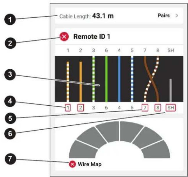
Table 16 shows a wire map of a cable test that failed for multiple reasons.
Table 16. Multiple Failures
| Item Description | |
| 1 | Pairs 1,2 are the shortest pair of the cable and open at 43.1 m. |
| 2 | The Product detected the Remote ID, and the wire map failed. The wires are not wired correctly based on the settings selected for the test. |
| 3 | The wire map shows how the cable is wired. The wire map passes or fails based on the settings selected for the test. For this test, the settings are set to test:A straight through cable.Allow Crossovercan be on or off to test a straight through cable.The continuity of the shield on the cable (Shield Test > )The test limit is set to ≥1000BASE-T (1G) to verify a 4-pair cable. |
| 4 | Pairs 1,2 fail because they are open. |
| 5 | Pairs 7,8 fail because they are a reverse pair. |
| 6 | The continuity of the shield fails because the continuity of the shield cannot be verified. |
| 7 | Because the wire map failed, the Product cannot test the performance capability of the cable. |
Open Pairs Failure
Figure 5 shows a wire map of a cable test that fails because wires 4, 5, 7, and 8 are open. The wires are not connected on the far end and the test limit is set to ≥1000BASE-T(1G) to verify a 4-pair cable. With a test limit set to 10BASE-T or 100BASE-TX, the wire map of the cable test passes. The length of the wires on the wire map indicates the distance to the open.
Figure 5. Open Pairs

Short Failure
Figure 6 shows a wire map that fails because wires 1 and 2 are shorted together. The length of the wire on the wire map indicates the distance to the short. With wires shorted together, the Product cannot detect the Remote ID. Repair the short and do the test again to verify the wire map of the other pairs.
Figure 6. Wires Shorted Together

Split Pairs Failure
Figure 7 shows a wire map of a cable test that fails because pairs 3,6 and 7,8 are split pairs.
Figure 7. Split Pairs

Test Limit Failure
Table 17 shows a cable test that fails because of near end cross talk (NEXT).
Table 17. NEXT Failure

| Item Description | |
| 1 | The Product detected the Remote ID, and the wire map passed. |
| 2 | The wire map passes because:The wires are all connected correctly on both the near and far ends for a straight through cable.Allow Crossover can be on or off to test a straight through cable.The continuity of the shield is not included as part of the test. (Shield > ). |
| 3 | The test fails because the test limit is set to verify the cable can support a 2.5BASE-T (2.5G) data rate throughput.The cable can support 10BASE-T (10), 100BASE-TX (100), and 1000BASE-T (1G) data rate throughputs.The cable cannot support 2.5BASE-T (2.5G) data rate throughput. |
Wi-Fi Tests Menu
Table 18 is a list of the menus available in the Wi-Fi Tests menu.
Table 18. Wi-Fi Tests Menu
| Menu Function | ||
 | Settings | Wi-Fi Enabled: Use to enable and disable the Wi-Fi radio. Forget All Networks: Use to delete the credentials of the saved networks. |
 | Networks | Tap to view details about available networks. See Networks. |
 | Channels | Tap to view details about channels. See Channels Screen. |
 | Access Points | Tap to view details about the access points or radios on a network. See Access Points. |
Wi-Fi Symbols
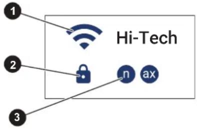
Symbols indicate features typical of Wi-Fi tests. The same symbol may show on more than one Wi-Fi screen. Table 19 shows examples of the Wi-Fi symbols.
Table 19. Wi-Fi Symbols
 | |
| Item Description | |
| 1 | Indicates the strength of the Wi-Fi signal as high, medium, low, or none. |
| 2 | Indicates the security level of the network. : Strong encryption : Weak encryption : Open |
| 3 | Indicates available Wi-Fi types. |
Wi-Fi Notes
The Product may detect error conditions about the Wi-Fi environment. An error may show on more than one Wi-Fi screen. An error shows in orange text as a note on a network or access point screen. For an example, see 3 in Table 26.
The Product may detect these errors:
- The access point is on an illegal channel for the detected region.
- The access point overlaps with an access point on an adjacent channel.
- The access point uses weak security.
Networks
Use the network feature to:
• View available networks.
• View the details of a network.
- Select a network to do a test.
- Save the results of a test.
Networks Screen
Table 20 shows the features on the Networks screen.
Table 20. Networks Screen

| Item Description | |
| 1 | Network name. Tap to open the Network Details screen to do a test. See Network Details Screen. |
| 2 | Tap to open the Sort menu to select to sort the networks by Signal Strength (dBm), Name (A-Z), or Security. |
| 3 | Tap to reverse the sort order the networks. For example, with sort by Name (A-Z) selected, tap to sort by Name (Z-A) and vice versa. |
| 4 | Number of radios/access points in a network. |
Network Details Screen
Table 21 shows the features of the Network Details screen.
Note
A Wi-Fi test is for Information only. The test does not pass or fail even though a ping result inside a test may pass or fail.
Table 21. Network Details Screen
 | |
| Item Description | |
| 1 | BSSID |
| 2 | Access point name. Not all access points have or transmit a name. |
| 3 | Security type |
| 4 | TEST button. Tap to start a test on the access point or radio with the greatest signal strength. Usually, the access point or radio that shows at the top of the list has the greatest signal strength. See Wi-Fi Connection Test Screen. |
| 5 | Channel number.A black number indicates the channel is legal in the region for which the Product is configured.A red number indicates the channel is illegal in the region for which the Product is configured. |
| 6 | The Wi-Fi frequency band. |
Wi-Fi Connection Test Screen
Table 22 shows the features on the Wi-Fi connection test screen.
Table 22. Wi-Fi Connection Test Screen

| Item Description | |
| 1 | Shows the strength of the signal in dBm over time. The data on the graph updates until the test stops. |
| 2 | Shows the transmission (Tx) and reception (Rx) rates in Mbps over time. The data on the graph updates until the test stops.The red line indicates the negotiated transmission rate from the Product to a connected access point or radio.The blue line indicates the negotiated reception rate of the Product from a connected access point or radio. |
| 3 | Additional information about the access point or radio: Country Code, Channel Range, Channel Bandwidth. |
| 4 | Ping information. See (4) in Table 11. |
| 5 | STOP button. Tap to stop a test to save the results.The STOP button changes to a SAVE AS... button. When there is memory available to save the result, tap SAVE AS... to save the result. See Save a Test Result. |
| 6 | The last reported Tx/Rx rate values. |
| 7 | The last reported signal strength value. |
Channels Screen
Use Table 24 to see the important features for channel utilization. Use Table 25 to see the important features about the signal strength of an access point. On the Product, these features show on the same screen (Table 23).
The Channels screen (Table 23) shows:
- Frequency band
• Channel numbers (X-axis)
• Channel utilization (left Y-axis)
• Wi-Fi signal strength (right Y-axis) - Access points
- Channel overlap
Table 23. Channels Screen

Table 24. Channel Utilization

Table 25. Access Point Signal Strength

| Item Description | |
| 1 | An access point. |
| 2 | The signal strength of an access point in dBm. |
| 3 | The number of access points on the same channel with the same signal strength. |
| 4 | The total number of access points on a channel. For example, channel 40 contains 4 access points. |
Access Points
Use the Access Points feature to:
• View available access points.
• View the details of an access point.
- Select an access point or radio to do a test.
- Save the results of a test.
Access Points Screen
Table 26 shows the features on the Access Points screen.
Table 26. Access Points Screen
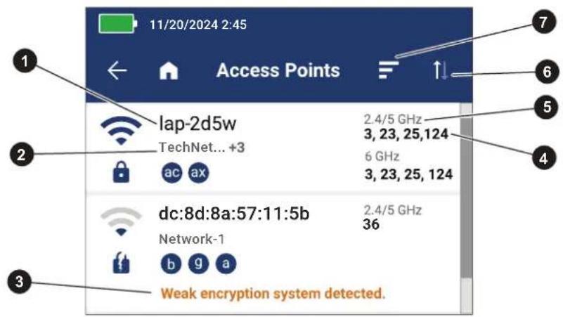
Item Description
| 1 | Access point name or BSSID |
| 2 | The networks that the access point offers. One name shows. If the access point offers more than one network, the additional number of networks show as a plus sign and a number. To see the names of all the networks offered on an access point, tap on the name of the access point.Tap on the access point to view the Access Point Details screen to see more information about the access point or to select a Wi-Fi network to do a test. See Access Point Details Screen Wi-Fi Test. |
| 3 | Notes appear in orange text. |
| 4 | Channels available on one of the Wi-Fi frequency bands (5). |
| 5 | The Wi-Fi frequency bands available on the access point. |
| 6 | Tap to reverse the sort order the access points. For example, with sort by Name (A-Z) selected, tap to sort by Name (Z-A) and vice versa. |
| 7 | Tap to open the Sort menu to select to sort the access points by Signal Strength (dBm), Name (A-Z), or Channel Number. |
Access Point Details Screen Wi-Fi Test
To use the Access Points screen to do a test:
1. Tap

The Access Points screen shows.
- Tap on an access point.
The Access Point Details screen shows.
-
Tap TEST.
-
Tap on a network.
Or,
For a hidden network, enter the appropriate name.
- If needed, use the on screen keyboard to enter the authentication information.
- The test starts automatically. See Wi-Fi Connection Test Screen.
Save a Test Result
To save a test:
-
On a test result screen, tap SAVE AS....
-
On a copper cable test, the length, remote id, and supported Ethernet rate save in the same result.
- On a copper switch test, switch, ping, and PoE results save in the same test result.
-
On a Wi-Fi test, the access point and network information, graphs, and ping results save in the same test result.
-
If necessary, use the onscreen keyboard to enter the Test ID, Project Name, and Operator Name.
-
Tap OK.
Results Menu
Table 27 shows an example of the Results menu.
Table 27. Results Menu

| Item Function | |
| 1 | Tap to view the results of all the projects or to select a single project to view the results from. |
| 2 | Shows the number of results selected to view.In the Project selection box (1):With All Projects selected, shows the total number of test results saved.With a single project selected, shows the number of test results saved in that project. |
| 3 | Shows the remainder of available results that can be saved in memory. The Product can save a maximum of 1000 results. |
| 4 | Shows the Test ID, Project Name, and the date and time of the test. |
| 5 | Tap to select which results to delete. See Delete Test Results. |
| 6 | Z: The result passed.✕: The result failed.i: The result is for information only. |
| 7 | √The result is uploaded to LinkWare PC.✕The result is not uploaded to LinkWare PC. |
| 8 | Tap to select how to sort the results: Oldest, Newest, Test ID (A-Z), Test ID (Z-A). |
Delete Test Results
To delete a test result:
- Tap Results > MANAGE RESULTS.
- Tap the box to the left of each result to delete.
- Tap DELETE.
- Tap OK.
To delete all of the test results:
- Tap Results > MANAGE RESULTS > SELECT ALL.
- Tap DELETE.
- Tap OK.
Upload Results to LinkWare PC
To upload results to LinkWare PC:
- Go to the home screen.
- Connect the USB-C end of the USB cable into the USB port on the Product. See Figure 8.
- Connect the USB-A end of the USB cable into a USB port on a PC.
- On a PC, use LinkWare PC to upload results.
Figure 8. Product to PC Connection

Tests with MS-IE-Adapter Set
To do a test with an MS-IE Adapter Set, see the MS-IE-Adapter Set QRG on www.flukenetworks.com.
Maintenance
Warning
To prevent possible electrical shock, fire, or personal injury:
- Do not open the case. You cannot repair or replace parts in the case.
- Use only specified replacement parts.
- Have an approved technician repair the Product.
Clean the Product
Clean the case and display with a soft cloth dampened with water and a mild soap solution. Do not use solvents, isopropyl alcohol, or abrasive cleansers.
To clean the ports, use a pressurized can of air or a dry nitrogen-ion gun, if available, to blow the particulates from the ports.
Battery
Note
The Product only operates on battery power. You cannot do a test while the battery charges.
Warning
To prevent possible electrical shock, fire, personal injury, or damage to the Product:
- Use only Fluke Networks approved power adapters to charge the battery.
- Batteries contain hazardous chemicals that can cause burns or explode. If exposure to chemicals occurs, clean with water and get medical aid.
- Do not disassemble the battery.
- Do not put battery cells and battery packs near heat or fire. Do not put in sunlight.
- Do not disassemble or crush battery cells and battery packs.
- Do not short the battery terminals together.
-
Use only the external mains power supply included with the Product.
-
Disconnect the battery charger and move the Product or battery to a cool, non-flammable location if the rechargeable battery becomes hot ( >50\ °C ) during the charge period.
- Replace the rechargeable battery after 5 years of moderate use or 2 years of heavy use. Moderate use is defined as recharged twice a week. Heavy use is defined as discharged to cutoff and recharged daily.
- To replace the battery, send the product to an authorized Fluke Networks Service Center, or see the LIQ-Battery Replacement Battery Instructions on our website.
To get the best performance from the lithium-ion battery:
- Do not charge the Product for more than 24 hours as a reduced battery life may result.
- Charge the Product for at least 1.5 hours every 6 months for maximum battery life. Without use, the battery will self-discharge in approximately 6 months.
Figure 9 shows how to charge the battery.
Figure 9. Charge the Battery

Product Specifications
For complete product specifications go to our website.


- CABLE+NETWORK TESTER
- LIMITED WARRANTY AND LIMITATION OF LIABILITY
- TABLE OF CONTENTS
- TITLE PAGE
- INTRODUCTION
- CONTACT FLUKE CORPORATION
- SAFETY INFORMATION
- PRODUCT FAMILIARIZATION
- FEATURES
- PARTS
- CONTROLS AND CONNECTIONS
- HANG STRAP
- DISPLAY
- MAIN MENU
- MENU CONTROLS
- GLOBAL SETTINGS MENU
- CONFIGURE A STATIC ADDRESS
- CHANGE THE IP ADDRESS OF THE PRODUCT
- CHANGE THE IP ADDRESS OF A DEVICE TO PING
- CONFIGURE AN IPV4 ADDRESS
- CONFIGURE AN IPV6 ADDRESS
- COPPER TESTS MENU
- COPPER TOOLS MENU
- COPPER SETTINGS MENU
- AUTOMATIC TEST DISCOVERY
- BEFORE A COPPER TEST
- WARNING
- SWITCH TESTS
- SWITCH CONNECTIVITY TESTS
- PING TESTS
- POWER OVER ETHERNET (POE) TESTS
- DEFINITIONS
- IN A POE TEST
- DO A SWITCH TEST
- SWITCH TEST RESULTS
- SWITCH TEST DETAIL RESULTS
- PING TEST RESULTS
- POE TEST RESULTS
- POE TEST PASS EXAMPLE
- POE TEST FAIL REASONS
- CABLE TESTS
- DO A CABLE TEST
- CABLE TEST RESULTS
- WIRE MAP SCREEN MULTIPLE FAILURES
- OPEN PAIRS FAILURE
- SHORT FAILURE
- SPLIT PAIRS FAILURE
- TEST LIMIT FAILURE
- WI-FI TESTS MENU
- WI-FI SYMBOLS
- WI-FI NOTES
- NETWORKS
- NETWORKS SCREEN
- NETWORK DETAILS SCREEN
- WI-FI CONNECTION TEST SCREEN
- CHANNELS SCREEN
- ACCESS POINTS
- ACCESS POINTS SCREEN
- ACCESS POINT DETAILS SCREEN WI-FI TEST
- TAP
- SAVE A TEST RESULT
- TO SAVE A TEST
- RESULTS MENU
- DELETE TEST RESULTS
- UPLOAD RESULTS TO LINKWARE PC
- TESTS WITH MS-IE-ADAPTER SET
- MAINTENANCE
- CLEAN THE PRODUCT
- BATTERY
- NOTE
- PRODUCT SPECIFICATIONS
Brand : FLUKE
Model : LinkIQ
Category : Computer and peripheral cables