
VIGI NVR2016H-16MP - VCR TP-LINK - Free user manual and instructions
Find the device manual for free VIGI NVR2016H-16MP TP-LINK in PDF.


| Product Type | Network Video Recorder (NVR) |
| Brand | TP-Link |
| Model | VIGI NVR2016H-16MP |
| Channels | 16 |
| Max Recording Resolution | 16MP |
| Video Compression | H.265 / H.264 |
| Dimensions (W x D x H) | 440 mm x 285 mm x 45 mm |
| Weight | 2.5 kg |
| Power Supply | DC 48V, 1.5A |
| Power Consumption | < 20 W (without HDD) |
| Hard Drive Support | Up to 2 SATA HDDs (each up to 10 TB) |
| Network Interface | 1 x Gigabit Ethernet RJ45 |
| Video Output | 1 x HDMI, 1 x VGA |
| Audio | 1 x Audio In, 1 x Audio Out |
| Alarm I/O | 4 x Alarm In, 1 x Alarm Out |
| Remote Access | Via TP-Link VIGI app or web browser |
| Operating Temperature | -10°C to 55°C |
| Storage Temperature | -20°C to 70°C |
| Cleaning Instructions | Use a soft, dry cloth. Do not use liquids or sprays. |
| Security Features | Password protection, HTTPS encryption, user access control |
| Repairability | Not user-serviceable. Contact TP-Link support for repairs. |
| Spare Parts | Contact TP-Link or authorized dealers |
Frequently Asked Questions - VIGI NVR2016H-16MP TP-LINK
User questions about VIGI NVR2016H-16MP TP-LINK
0 question about this device. Answer the ones you know or ask your own.
Ask a new question about this device
Download the instructions for your VCR in PDF format for free! Find your manual VIGI NVR2016H-16MP - TP-LINK and take your electronic device back in hand. On this page are published all the documents necessary for the use of your device. VIGI NVR2016H-16MP by TP-LINK.
USER MANUAL VIGI NVR2016H-16MP TP-LINK
About This Guide....1
Get Started 2
1.1 Connect the Hardware....3 1.2 Set Up NVR....4
Configure Your Network Camera....7
2.1 Add Cameras to the NVR....8
2.1.1 Add Cameras Singly or in Batches 8 2.1.2 Add a Camera to a Certain Screen....15 2.1.3 Add Cameras Manually....15 2.1.4 Modify IP Addresses of Cameras....17
2.2 Plug and Play Settings....19 2.3 Configure Image Effects....19
2.3.1 Configure Image Settings....19
2.4 Configure OSD Settings....23 2.5 Configure Privacy Mask 24 2.6 Configure Splicing (Only for Certain Models)....25 2.7 Configure Stream Settings 26
2.7.1 Configure Main Stream and Substream 26 2.7.2 Configure Audio....27 2.7.3 Configure ROI....28 2.7.4 Configure SRTP 29
2.8 Configure Pan&Tilt (Only for PT Cameras)....30
2.8.1 Preset and Call Positions 30 2.8.2 Preset and Call Paths in Patrol Scan....31 2.8.3 Preset and Call Patterns in Pattern Scan 32 2.8.4 Enable Park....33 2.8.5 Target Track 34 2.8.6 Preview Preset Settings....35
2.9 Configure PoE Channel (Only for PoE NVRs)....37
2.10 Manage Your Cameras 38
2.10.1 Modify Camera Connection Parameters....38 2.10.2 Change the Password and Reset Email....39 2.10.3 Upgrade the Firmware....40
2.10.4 Configure Scheduled Reboot....41 2.10.5 Load Default 42 2.10.6 Remove Cameras from the NVR....43
Live View 44
3.1 Configure the Screen Layout....45
3.1.1 Change the Screen Layout Quickly....45 3.1.2 Merge Screens in Settings....46 3.1.3 Rearrange Channels in Settings....48
3.2 Configure Live View Settings via Toolbar....50
3.3 Change Picture Mode 51
Recording and Storage....52
4.1 Configure Recording Schedules....53
4.1.1 Customize Recording Schedule 53 4.1.2 Configure Advanced Recording Settings....56
4.2 Recording Controls....57
4.2.1 Configure Storage Disk Group....57 4.2.2 Configure Disk Quota....58
4.3 Manage Hard Drive....59
4.3.1 View and Configure Settings of Hard Drive....59 4.3.2 Add External Hard Drive to NVR 61 4.3.3 Bad Sector Detection....61 4.3.4 S.M.A.R.T Detection....61
4.4 Expansion Storage (Only for some models)....63
4.5 Long-term Storage (Only for some models) 63 4.6 Backup Recordings....64 4.7 Search....64 4.8 Export Recordings....65
Playback....68
5.1 Instant Playback....69 5.2 Play Normal Recordings....69 5.3 Play Recordings with Tags....72 5.4 Playback Recordings of Events....74 5.5 Playback Operations....75
5.5.1 Basic Playback Operations....75 5.5.2 Set Smart Playback Rules....77
5.5.3 Edit Recordings....77
5.5.4 Export Recordings 78
Events and Alerts....80
6.1 Motion Detection....81
6.2 Camera Tampering 84
6.3 Human Detection....86
6.4 Vehicle Detection 89
6.5 Line Crossing Detection 92
6.6 Intrusion Detection 95
6.7 Region Entering Detection....98
6.8 Region Exiting Detection 101
6.9 Loitering Detection....104
6.10 Object Abandoned/Removal Detection....107
6.11 Scene Change Detection 110
6.12 Abnormal Sound Detection 113
6.13 Queue Detection....116
6.14 Smart Frame 119
6.15 VCA 119
6.16 Video Signal Loss Detection....122
6.17 Offline and IP Conflict 124
6.18 Disk Exception 125
6.19 Login Exception....126
6.20 Hardware Exception (Only for PoE models)....127
6.21 FTP Backup Exception (Only for Certain models) 128
6.22 Fan Exception (Only for certain models)....129
6.23 Alarm Device (Only for certain models)....130
6.24 Disarming....135
6.25 Alarm Server 136
6.26 Active Defense 137
Network Management....140
7.1 Configure Network Connection....141
7.1.1 Configure Basic Settings....141
7.1.2 Configure Advanced Settings....142
7.2 Configure Operating Mode (Only for certain models) 142
7.2.1 Configure Fault-tolerant Mode....143
7.2.2 Configure Multi-access Mode....144
7.2.3 Configure Port Aggregation Mode....146
7.3 Configure IPv6 147 7.4 Configure Network Isolation....149 7.5 Configure Network Service....149 7.6 Configure DDNS....151 7.7 Configure UPnP 152 7.8 Configure IP Restriction....153 7.9 Configure Platform Access....153 7.10 Configure Email 155 7.11 Configure ONVIF....156 7.12 Configure Openapi....157 7.13 Configure FTP 157 7.14 Configure LLDP 158 7.15 Configure SNMP....158
NVR Management 161
8.1 Upgrade the NVR Firmware 162 8.2 Reset the NVR....163 8.3 Configure Reboot Schedule for NVR 163 8.4 Diagnose the NVR....164
System Management....166
9.1 Configure Basic Settings....167 9.2 Modify System Time....168 9.3 Configure Interface Output....169 9.4 Configure Channel-Zero 169 9.5 Manage User Accounts....170 9.6 Import and Export Settings....172 9.7 View System Logs....174 9.8 View System Information....176
About This Guide
This User Guide provides information for using and managing NVR. It explains functions of NVR and shows you how to configure them.
Conventions
When using this guide, notice that:
Features available in NVR may vary due to your region, device model, and firmware version. All images, steps, and descriptions in this guide are only examples and may not reflect your actual experience. The information in this document is subject to change without notice. Every effort has been made in the preparation of this document to ensure accuracy of the contents, but all statements, information, and recommendations in this document do not constitute the warranty of any kind, express or implied. Users must take full responsibility for their application of any products. This guide uses the specific formats to highlight special messages. The following table lists the conventions that are used throughout this guide.
| Underlined Indicates hyperlinks. You can click to redirect to a website or a specific section. | |
| Bold | Indicates contents to be emphasized and texts on the web page, including the menus, tabs, buttons and so on. |
| > The menu structures to show the path to load the corresponding page. | |
| Caution | Reminds you to be cautious, and Ignoring this type of note might result in device damage or data loss. |
| Note Indicates information that helps you make better use of your device. | |
More Information
For technical support, the latest version of the User Guide and other information, please visit https://www.tp-link.com/support. The Quick Installation Guide can be found where you find this guide or inside the package of the product. To ask questions, find answers, and communicate with TP-Link users or engineers, please visit https://community.tp-link.com to join TP-Link Community.
1
Get Started
This chapter guides you on how to set up your NVR for the first time. The quick setup wizard brings you convenience and flexibility to configure NVR. This chapter includes the following sections:
- Connect the Hardware
- Set Up NVR
The VIGI network video recorder (NVR) coordinates with camera systems to help you view, store, and playback videos. With the support of ONVIF, you can easily add cameras of different brands. Also, it supports detecting events and sending you up-to-date notifications. Moreover, you can manage and monitor the NVR and cameras remotely via the VIGI app. VIGI NVR2016H-16MP (V2) is used as an example in this guide.
1.1 Connect the Hardware
To manage multiple cameras, you should prepare a network device, such as a switch or a router. Connect the NVR and cameras to the network device to ensure they are in the same network.
Follow the steps below to complete the hardware connection.
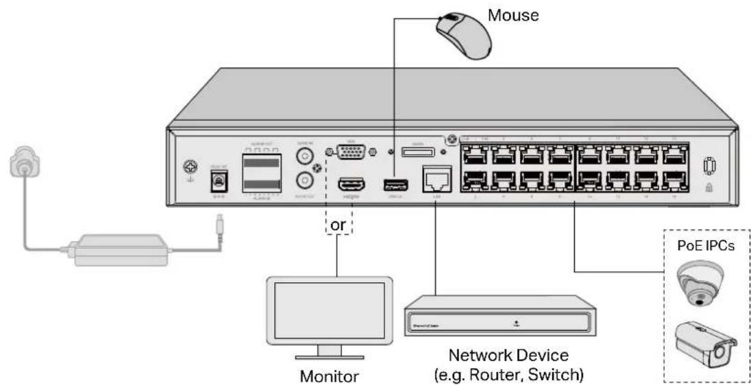
- Connect your monitor to the HDMI or VGA port according to the connection port it supports.
- Connect your monitor to a power source.
- Connect the LAN port of the NVR to a network device with an Ethernet cable.
- Connect the provided USB Mouse to the USB Interface of the NVR.
- Connect the power adapter to the NVR.
- Connect the cameras to the network device.
- Turn on the monitor and you will enter the NVR's GUI.

1.2 Set Up NVR
With a user interface displayed on the monitor, it is easy to configure and manage the NVR. You will see the following page.

1. Confirm the Basic Information.
Device Name: Displays the name of the device. You can change it as needed.
Language: Set the system language of the NVR.
Country/Region: Set the location of the NVR.
| Power Line Frequency | Set the Power line frequency consistent with local utility settings to eliminate image flickering associated with fluorescent lights. |
| System Time | Displays the system time of the NVR. You can click the Settings button to configure the time settings. Refer to Modify System Time for detailed instructions. |
| Hard Drive(s) | Displays the external hard drive details. You can click the Settings button to manage the hard drive. Refer to Manage Hard Drive for detailed instructions. |
| Network | Displays the network connection status of the NVR. You can click the Settings button to configure the network settings. Refer to Configure Network Connection for detailed instructions. |
Cloud Service: Toggle on to allow the NVR to connect to the cloud service.
2. Configure the account settings.
| Username | Displays the name used to log in to the NVR. It is admin by default and cannot changed. |
| New Password Set the password of your NVR. | |
| Confirm Password Confirm the password of your NVR. | |
| Camera's Password | Set a password for cameras added to your NVR. The password will be applied to the uninitialized cameras. |
| NVR Password Recovery | Set an email address or security questions to reset the password of your NVR. |
| Camera Password Recovery | Set an email address or security questions to reset the password of your cameras. |
| Same as the NVR | (Optional) Click the checkbox if you want to apply the password and the email address of the NVR to your cameras. |
- Select the device you want to add automatically and click Next. You can also click Step-by-step Setup to manually set up the NVR and add cameras.
- (Optional) Bind the NVR to your TP-Link ID for remote management. Click Complete.

- Set the gesture password for easy login. If you don't want a gesture password, click Skip.

- Done. The set up is complete, and you will enter the Live View page.
2
Configure Your Network Camera
This chapter introduces how to add your cameras to NVR and configure them. You can customize image effects and configure OSD (On Screen Display), Privacy Mask, Splicing, Stream, and Pan&Tilt. This chapter contains the following sections:
- Add Cameras to the NVR
- Plug and Play Settings
- Configure Image Effects
- Configure OSD Settings
- Configure Privacy Mask
- Configure Splicing (Only for Certain Models)
- Configure Stream Settings
- Configure Pan & Tilt (Only for PT Cameras)
- Configure PoE Channel (Only for PoE NVRs)
- Manage Your Cameras
2.1 Add Cameras to the NVR
The VIGI NVR can add cameras singly, in batches, or to a certain screen. You can also manually add cameras by entering their IP addresses and passwords. The processes vary depending on whether the camera is initialized and whether Plug and Play is enabled. TP-Link security cameras are uninitialized by default.
Choose one of the methods below and follow the steps to add your cameras:
■ Add Cameras Singly or in Batches ■ Add a Camera to a Certain Screen ■ Add Cameras Manually
Connect cameras to the same network as the NVR. When adding TP-Link security cameras with different IP segments, the NVR will automatically modify the IP addresses to ensure every camera has a unique IP address and they are in the same subnet as your NVR. To add cameras from other brands, it is recommended to refer to their user guides before adding. If the cameras cannot be automatically found by the NVR, refer to Add Cameras Manually.
2.1.1 Add Cameras Singly or in Batches
Add Uninitialized Cameras
■ When Plug and Play Enabled
Note: After you connect the cameras to the network device, stay in the Live View screen and wait for the NVR to add the cameras automatically.
- Right-click on the Live View screen and click Add Camera in the pop-up Main Menu. Alternatively, right-click on the Live View screen and click Settings in the pop-up Main Menu, then go to Camera > Device Access > Add Device.

- Click + to add a single camera. If you want to add cameras in batches, click the checkbox of cameras and click Add in Batches.

- After the cameras are added, you can view the cameras in the Device Added list.

■ When Plug and Play Disabled
Follow the steps below to add the cameras.
- Right-click on the Live View screen and click Add Camera in the pop-up Main Menu. Alternatively, Right-click on the Live View screen and click Settings in the pop-up Main Menu, then go to Camera > Device Access > Add Device.

- Click + to add a single camera. If you want to add cameras in batches, click the checkbox of cameras and click Add in Batches.

- Set a password for your cameras. Click Add. After the cameras are added, you can view the cameras in the Device Added list.

Add Initialized Cameras
■ When Plug and Play Enabled
When plug and play is enabled, follow the steps below to add cameras.
- Right-click on the Live View screen and click Add Camera in the pop-up Main Menu. Alternatively, Right-click on the Live View screen and click Settings in the pop-up Main Menu, then go to Device Access > Add Device.

- Click + to add a single camera. If you want to add cameras in batches, click the checkbox of cameras and click Add in Batches.

- Click ☐ Edit in the Device Added list. Then enter the password in Edit Channel and click Save. After a successful verification, the connection status will change from Not certified to Connected.
Note: If the camera's password is the same as the NVR's preset password, the connection status will be Connected directly.

■ When Plug and Play Disabled
When plug and play is disabled, follow the steps below to add cameras.
- Right-click on the Live View screen and click Add Camera in the pop-up Main Menu. Alternatively, Right-click on the Live View screen and click Settings in the pop-up Main Menu, then go to Camera > Device Access > Add Device.

- Click + to add a single camera. If you want to add cameras in batches, click the checkbox of cameras and click Add in Batches.

- Enter the password manually to verify it. Click Add. After the cameras are added, you can view the cameras in the Device Added list.

2.1.2 Add a Camera to a Certain Screen
You can add a camera to a certain channel in the Live View screen. Follow the steps below to finish the configuration.
- Click a screen in the Live View screen and click on the bottom left corner.

2. Click


- Follow the web instructions to add the camera.
2.1.3 Add Cameras Manually
If the devices cannot be automatically found by the NVR, you can add cameras manually using its information. Follow the steps below to finish the configuration.
- Right-click on the Live View screen and click Add Camera in the pop-up Main Menu. Alternatively, Right-click on the screen and click Settings in the pop-up Main Menu, then go to Camera > Device Access > Add Device.
2. Click Add Manually.

3. Enter the information of the camera to add it. For VIGI security camera, enter the IP address and password. Click Add.

IP Address The IP address of the camera.
Control Protocol
Select a protocol that your camera supports. The global protocol that allows surveillance and security devices from different manufacturers to operate together seamlessly.
| Transfer Protocol | TCP(Transfer Control Protocol) that provides reliable, ordered delivery of a stream of bytes from one device to another device. |
| Management Port | The management port to configure, maintain, and support a network device. |
| Username The username of the camera. | |
| Password The password of the camera. | |
2.1.4 Modify IP Addresses of Cameras
To avoid IP conflicts and ensure your cameras are in the same subnet, you can modify the IP addresses manually. Follow the steps below to complete the configuration.
- Right-click on the Live View screen and click Add Camera in the pop-up Main Menu. Alternatively, right-click on the Live View screen and click Settings in the pop-up Main Menu, then go to Camera > Device Access > Add Device.
- Select the checkbox(es) of the camera(s) and click Modify IP Address. You can select multiple cameras to modify their IP addresses in batches.

- Set the starting IP address you assigned for the camera(s). Click Yes.

- Click Apply to confirm the new IP address(es).
Note: The IP address(es) will be assigned to the camera(s) in order.

2.2 Plug and Play Settings
The Plug and Play function enables the NVR to automatically find and add cameras. You can enable or disable this function according to your needs. To configure and view the settings, right-click on the Live View screen and click Settings in the pop-up Main Menu, then go to Camera > Device Access > Plug and Play.

■ Add Without Login
The NVR will automatically discover and add cameras in the same network without requiring you to log in to the NVR.
■ Device Access Alert
If a new camera is found when the channels are full, your NVR will receive a notification.
■ Devices Limited to Access
After the cameras are added to the NVR, they will be automatically added to the list, which means they cannot be added to the NVR again automatically. If you want to automatically add the cameras for the second time, remove the cameras from the devices limited access list.
2.3 Configure Image Effects
To adjust the image effect, you can configure the picture mode and image settings.
2.3.1 Configure Image Settings
- Right-click on the Live View screen and click Settings in the pop-up Main Menu. Go to Camera > Display > Image.
2. Select a channel and configure the following parameters.
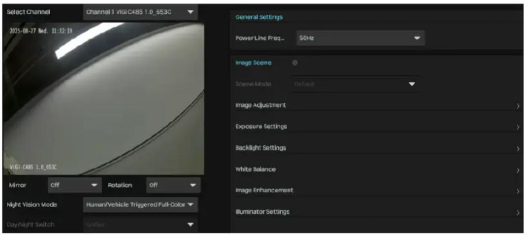
Mirror: Select the mirror mode as needed.
Off: The image displays normally.
Left-Right: Mirror the image on the vertical axis.
Up-Down: Flip the image on the horizontal axis.
Center: Rotate the image by 180 degrees around its center.
Rotation: Choose to turn the live view image by 90 or 270 degrees on your display. When you select Off, the image displays normally.
| Night Vision Mode | Human/Vehicle Triggered Full-Color: The camera switches to the full-color mode once it detects a person or vehicle. |
| Auto Color: The camera turns on or off the white supplement light according to the light condition of the environment. | |
| Auto IR: The camera turns on or off the IR supplement light according to the light condition of the environment. | |
| White LED Always On: White supplement light is on. | |
| IR Always On: IR supplement light is on. | |
| Off: Supplement light is off. | |
| Custom: Select it to configure Day/Night Switch and Illuminator. | |
| Day/Night Switch | Select a method to switch the image settings of day and night.Unified: The camera applies the same image settings throughout a dayScheduled: The camera switches the image mode of day and night at your specified time. If you select this method, adjust the slide bar to specify the switch time.Auto: The camera switches the image mode of day and night automatically according to the light condition of the environment. |
| General Settings | Powerline Frequency: Tailor the light refresh time to different environments |
| Image Scene Select a display mode — Realistic, Balanced, Vivid, or Custom. The settings below will automatically adjust based on your selection. | |
| Image Adjustment | Brightness: Adjust the brightness of image. The image gets brighter when the value increases.Contrast: Adjust the brightness of image. The image gets brighter when the value increases.Saturation: Adjust the saturation of image. The color of image gets richer when the value increases.Sharpness: Adjust the sharpness of image. The image gets sharper when the value increases. |
| Exposure Settings | Exposure: Select a exposure mode. Auto: The camera adjusts the exposure automatically. If you select Auto, specify the exposure scale. The image gets brighter when the scale increases.Manual: The image exposure is fixed. If you select Manual, adjust the slide bar of Gain to specify the exposure gain, and select a shutter speed. The image gets brighter when the gain increases or the shutter speed gets slower.Low Motion Blur: Low motion blur occurs when a moving object is captured over a longer exposure time, resulting in a streaked or blurred image.Anti-flicker: If you notice flickering or overexposed camera images, check and change the anti-flicker settings to see if that resolves the issue. We recommend that you choose to turn it off when installing the camera outdoors. |
| Backlight Settings | BLC Area: BLC (Backlight Compensation) can clear the dark area of the video. Select a position and the camera adjusts the exposure based on the light intensity in the area.WDR: WDR (Wide Dynamic Range) can improve the image effects in backlit scenes. If you select On, the camera balances the light of the brightest and darkest areas automatically.HLC: HLC (Highlight Compensation) can senses strong sources of light in video and compensates for exposure on these spots to enhance the overall quality. |
| White Balance Select a mode and the camera will adjust the color temperature to display the image approximated to the realistic vision effects. | |
| Auto: The camera adjusts the color temperature automatically. | |
| Locked: The camera keeps the current color settings all the time. | |
| Daylight/Natural Light/Incandescent/Warm Light: The camera adjusts the color temperature to remove the color casts caused by the corresponding light. | |
| Current: The camera keeps the current color settings all the time. | |
| Custom: Adjust the slide bar to configure the color temperature, and the camera keeps the settings all the time. | |
| Image Enhancement | Prevent Overexposure to infrared light: Select a mode to prevent overexposure to infrared light when objects get close to the camera at night. If you select Manual, adjust the slide bar to specify an exposure scale. |
Illuminator Settings
Select a mode to decide the usage of infrared light. The available options vary due to the mode you select in Day/Night Switch.
Auto: The camera enables the infrared light automatically when it detects the environment turns dark, and disables when the environment is bright enough.
Schedule: Specify the time to enable and disable infrared light.
Always On/Off: The camera enables/disables the infrared light all the time.
Sensitivity: Specify Sensitivity to decide the light intensity that can trigger the switch of infrared light. The infrared light is easier to be triggered when the sensitivity decreases.
Delayed Switch: Decide how long the camera waits to enable or disable the infrared light when the environment reaches the light condition.
Lighting Mode: Select the fill light mode which affects the anti-overexposure strategy and image.
Infrared Lighting: The image is black and white.
Human/Vehicle Trigger Full-Color: The camera turns on the full-color mode once it detects a person or vehicle.
White Light Illumination: The image is full-color and the white light will be turned on at the same time. It includes three modes, standard, soft, and custom.
White Light Intensity: Select the white light intensity.
Manual: You can drag the Level bar below to manually control the brightness of the fill light.
Smart White Light-Standard: The camera automatically controls the brightness of the fill light.
Smart White Light-Soft: The camera automatically controls the brightness of the fill light, which is no different from Standard. Soft refers to softening the overexposed area in the image.
2.4 Configure OSD Settings
You can configure OSD (On Screen Display) to edit the information displayed in Live View and recordings. Follow the steps below to configure OSD.
- Right-click on the Live View screen and click Settings in the pop-up Main Menu. Go to Camera > Display > OSD.
- Select a channel, click the checkbox to display or hide the information, and select a display effect. Click Save.
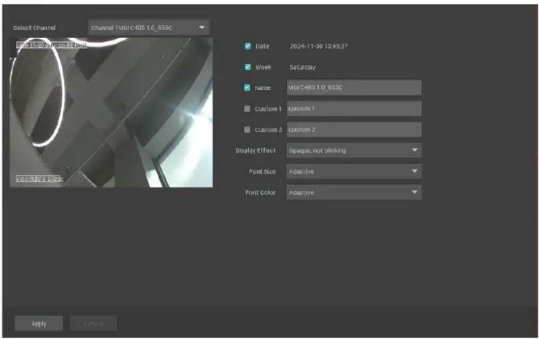
Note: If you change Name in the OSD setting, you also change the camera name.
2.5 Configure Privacy Mask
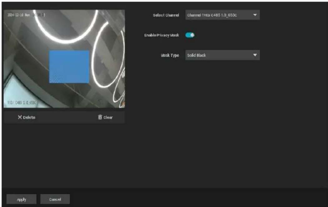
With Privacy Mask, you can set privacy area in the image. The area cannot be recorded and monitored.
Follow the steps below to configure Privacy Mask.
- Right-click on the Live View screen and click Settings in the pop-up Main Menu. Go to Camera > Display > Privacy Mask.
- Select a channel and enable Privacy Mask. Draw the privacy areas on the preview screen (the blue squares in the picture below), you can select to use a solid type or mosaic type. Use the mouse to
adjust the size and location of areas. To remove a certain privacy area, select it and click Delete. To remove all privacy areas, click Clear. Click Apply to finish the configuration.
2.6 Configure Splicing (Only for Certain Models)
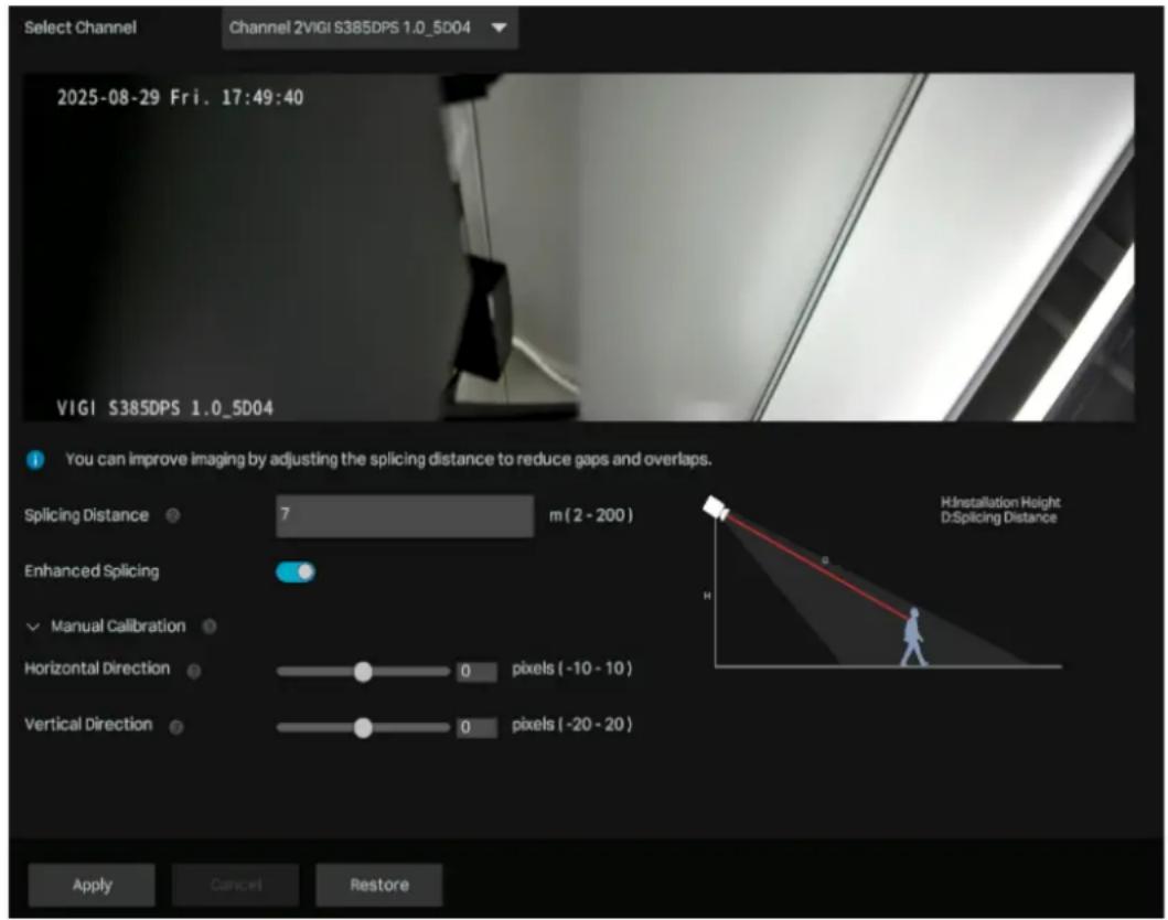
For dual-sensor panoramic camera, you can merge two video feeds into a cohesive image. It is crucial to establish an optimal Splicing Distance according to your specific application scenario.
- Right-click on the Live View screen and click Settings in the pop-up Main Menu. Go to Camera > Display > Splicing.
- Select a channel and adjust the splicing distance to reduce gaps and overlaps to improve the imaging. You can also manually fine-tune the stitching position of the two images to achieve better imaging. Click Apply to finish the configuration.
2.7 Configure Stream Settings
In Stream Settings, you can configure video stream levels and ROI (Region of Interest) level.
Video stream levels decide the video quality in Live View and recording for each channel, and you can adjust the video quality of a certain area by specifying the ROI level.
2.7.1 Configure Main Stream and Substream
The NVR supports two stream levels: main stream and substream. In Live View, the NVR decides which stream is applied to the channels automatically based on network bandwidth and device performance. In Recording Controls, you can apply them to the channels to record with different stream settings. After configuring the streams, refer to 4.2 Recording Controls to apply them to recordings.
Follow the steps below to configure the stream settings.
- Right-click on the Live View screen and click Settings in the pop-up Main Menu. Go to Camera > Stream > Videos.
- Select a channel and configure the following parameters. Click Apply.
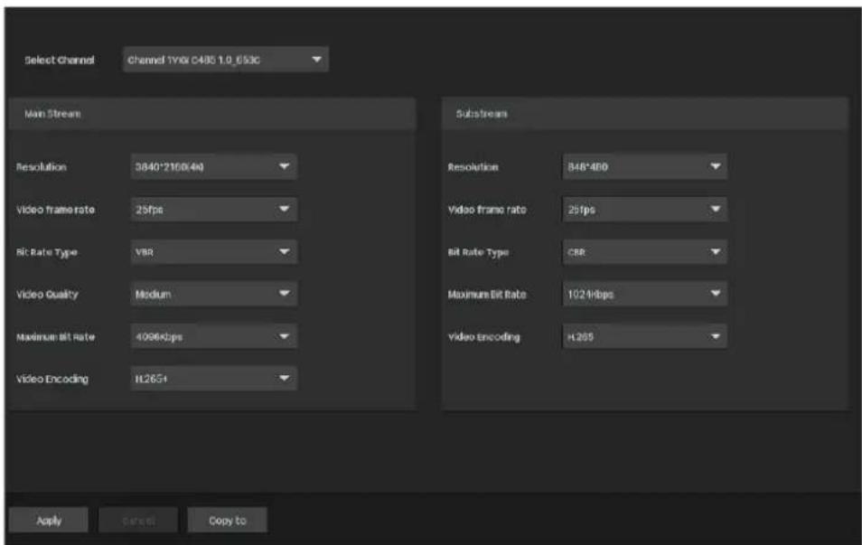
| Resolution Specify the resolution of the video stream. The screen displays images more clearly when the resolution increases. | |
| Video Frame Rate | Specify the frame rate of videos. The video is more fluent when the rate increases. |
| Bit Rate Type Select a type of bit rate. | |
| VBR: The bit rate changes with the image within Maximum Bit Rate. | |
| CBR: The bit rate is Maximum Bit Rate all the time. | |
| Video Quality When VBR selected as the bit rate type, set the video quality as high, medium, or low. | |
| Maximum Bit Rate | When VBR selected as the bit rate type, specify the upper limit of bit rate. |
| When CBR selected as the bit rate type, specify the bit rate. | |
| Video Encoding Select the encoding type of the stream. Compared with H.264, H.265 is improved in reducing the file size and saving the bandwidth. | |
- (Optional) If you also want to apply the stream settings to other channels, click Copy to Other Channels and select the channels. Click Apply.
2.7.2 Configure Audio
In Audio, you can configure the audio output and input settings.
- Right-click on the Live View screen and click Settings in the pop-up Main Menu. Go to Camera > Stream > Audio.
Select a channel and configure the settings as needed.

| Audio Output Settings | Audio Output: Set the audio output device. |
| Mute: The speaker is muted/not muted. | |
| Output Volume: Set the Two-Way Audio volume of the speaker. | |
| System Volume: Set the alarm volume of the speaker. | |
| Audio Input Settings | Audio Coding: Set the audio encoding format of the microphone. |
| Audio Input: Set the audio input device. | |
| Input Volume: Set the volume of the microphone. | |
| Noise Filtering: Microphone ambient noise filtering function is enabled/disabled. | |
| Audio Switch: The microphone is muted/not muted. If it is enabled, the microphone will collect audio data. |
2.7.3 Configure ROI
In ROI, you can configure the interest level of a specified area in each channel. The level 1–6 is ranked from low to high. The higher the ROI level, the better image quality.
- Right-click on the Live View screen and click Settings in the pop-up Main Menu. Go to Camera > Stream > ROI.
- Select a channel, set the stream type and enable ROI. Draw an area on the preview screen (the blue square in the picture below). Use the mouse to adjust the size and location of areas. Specify the ROI level, specify the area name and click Apply.

2.7.4 Configure SRTP
If you enable SRTP, the video data will be encrypted and you may be unable to play the video using the third-part clients or NVRs. To use this feature, the camera also should support SRTP.
Right-click on the Live View screen and click Settings in the pop-up Main Menu. Go to Camera > Stream > Advanced Settings. Select a channel, enable SRTP and click Apply to save the settings.

2.8 Configure Pan&Tilt (Only for PT Cameras)
In Pan&Tilt, you can preset the positions, paths and pattern for each channel and call a preset to change the status of lens quickly and conveniently. Also, you can enable Park to trigger the preset automatically when there is no operation.
Note: Only the cameras with Pan&Tilt support this feature. Some of the Pan&Tilt features are only supported by some models.
2.8.1 Preset and Call Positions
The settings of a position include the direction of lens, the status of zoom and focus, and the rotation speed. Follow the steps below to preset a position.
- Right-click on the Live View screen and click Settings in the pop-up Main Menu. Go to Pan & Tilt.
- Select a channel listed on the left panel, click Preset, and select a Preset number from the dropdown list. Click the buttons to adjust the position and adjust the slide bar to specify the Pan&Tilt speed. Click Set as Preset to save the Preset settings.


Use the eight directional buttons to adjust the lens direction. Click the directional button to rotate a certain degree in the corresponding direction. Long press the button to continuously rotate in the corresponding direction.

Click to restore to the default position.

Click to zoom out. Long press to continuously zoom out.

Click to zoom in. Long press to continuously zoom in.

Click to adjust the focus and the near objects get clearer.

Click to adjust the focus and the distant objects get clearer.

Lens Initialization. Click to Initialize the lens and focus again for a clear image.

Auxiliary Focus. Click to focus automatically.
To call the preset, select a Preset number and click Call. Then, the camera will adjust to the position.
2.8.2 Preset and Call Paths in Patrol Scan
In Patrol Scan, you can configure paths for patrol. A path consists of several preset positions, and your camera stays in each position for a preset duration.
Note: Before configuring Patrol Scan, you need preset the positions that the path involves.
Follow the steps below to preset a path.
- Right-click on the Live View screen and click Settings in the pop-up Main Menu. Go to Pan&Tilt.
- Select a channel listed on the left panel, click Patrol Scan, and select a Patrol Path number from the drop-down list. Click Add Patrol Preset to add the position and enter the seconds that the camera stays. Click Apply to save the Patrol Path settings.

To call the preset, select a Patrol Path number and click Call. Then, the camera patrols following the configured path.
2.8.3 Preset and Call Patterns in Pattern Scan
In Pattern Scan, you can record the movement to customize the patterns. Follow the steps below to preset a pattern.
- Right-click on the Live View screen and click Settings in the pop-up Main Menu. Go to Pan&Tilt.
- Select a channel listed on the left panel, click Pattern Scan, and select a Pattern Path number from the drop-down list. Click Start Recording and click the buttons to adjust the position. Click Stop Recording to save the movements as a pattern.

To call the preset, click Call, and the camera moves following the recorded pattern.
2.8.4 Enable Park
When Park enabled, the camera will perform the preset position, path, or pattern automatically if there is no operations in specified time. Follow the steps below to enable Park.
- Right-click on the Live View screen and click Settings in the pop-up Main Menu. Go to Pan&Tilt.
- Select a channel listed on the left panel and click Park. Enable Park, select a mode and a preset, and enter the park time. Click Apply.

Park Mode: Select a mode to decide what kind of preset the camera will perform.
Park Mode ID: Select a preset from the drop-down list. The presets in the list vary based on the selected park mode.
Park Time: When there are no operations during this time, the camera will perform the preset.
2.8.5 Target Track
When Target Track is enabled, the camera will track the target person automatically. Follow the steps below to enable Target Track.
- Right-click on the Live View screen and click Settings in the pop-up Main Menu. Go to Pan & Tilt.
- Select a channel listed on the left panel and click Target Track. Enable Target Track, enable smart detection. Click Apply.

Target Track: Choose whether to enable or disable Target Track.
Object
Classification
Enable human detection to allow tracking humans.
2.8.6 Preview Preset Settings
Follow the steps below to preview all Preset settings and edit the preset name.
- Right-click on the Live View screen and click Settings in the pop-up Main Menu.
- Go to Pan & Tilt. Select a channel listed on the left panel and click Preview.

- Select a preset mode to view the presets. Click the icons in the list to adjust the position, preview the preset, and edit its name.


Click to enable 3D positioning. Use the mouse to adjust the position of the camera.
Click a point on the screen, and the point will be moved to the center of the screen.
Hold down the left mouse button and draw a rectangular area from left to right. Then the camera zooms in, focusing on the specified area.
Hold down the left mouse button and draw a rectangular area from right to left. Then the camera zooms out, focusing on the specified area.

Click to enable Center. Click a point on the screen, and the camera adjusts its position to center on the point.

Click to enable Park. To configure the park mode and time, click Pan & Tilt Settings at the bottom and click the Park tab.

Click the preset in the list and click the icon to edit the name.

(Only for Preset) Click to move to the preset position.

(Only for Cruise Scan and Pattern Scan) Click to perform the Cruise or Pattern scan.

(Only for Cruise Scan and Pattern Scan) Click to stop the scan.
2.9 Configure PoE Channel (Only for PoE NVRs)
In PoE channel, you can check the port status, rated power, change the port status, and configure the port settings to determine whether the port can provide power supply.
- Right-click on the Live View screen and click Settings in the pop-up Main Menu. Go to Camera > PoE Channel.
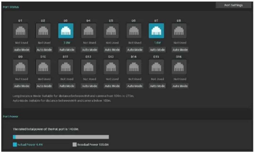
Port Status: Click to change port mode.
Auto Mode: This mode is suitable for distances between NVR and camera below 100m.
Long Distance Mode: This mode is suitable for distances between NVR and camera from 100m to 270m.
Port Settings: Click to configure port settings. Select the port, and set its power priority, power status, and maximum power.

2.10 Manage Your Cameras
For an added camera, you can manage its name, network configurations, account, firmware, and restart time, or just remove it.
2.10.1 Modify Camera Connection Parameters
Note: The cameras should be in the connected status.
- Right-click on the Live View screen and click Settings in the pop-up Main Menu. Go to Camera > Device Access > Add Device.
2. Click the table and modify the name. Click Save.

Name: Specify the camera name.
Control Protocol
Display the protocol used to control the camera.
Transport Protocol
Displays the protocol used for communication.
Management Port: Specify the management port.
2.10.2 Change the Password and Reset Email
You can change the device password and reset email to enhance security.
- Right-click on the Live View screen and click Settings in the pop-up Main Menu. Go to Camera > Device Management > Password Management.
- To change the settings of a single camera, click ☑ in the table. To change the password of multiple cameras in batches, select the cameras and click Change Password. Enter the new settings and click Save.

Note:
• The cameras should be in the connected status. - If you click Use Preset Camera Settings, the camera uses the password and reset email configured in NVR Quick Setup. To view and modify the preset camera settings in NVR, go to System > User Management in Settings and click ☑ of the administrator. - If you have added a camera to the NVR but cannot find it in the table, check the connection to make sure the camera is connected properly. Click Refresh to refresh the data.
2.10.3 Upgrade the Firmware
Two methods are supported to upgrade the firmware: Local Upgrade and Online Upgrade. Follow the steps below to upgrade the firmware.
- Get ready to upgrade the firmware.
- (For Local Upgrade) Place the firmware in an external storage device and plug the external storage device into the NVR. • (For Online Upgrade) Connect the NVR and cameras to the internet first.
- Right-click on the Live View screen and click Settings in the pop-up Main Menu. Go to Camera > Device Management > Firmware Upgrade.
- Select the cameras and click Local Upgrade or Online Upgrade to upgrade them.

• For Local Upgrade, select the firmware from the external storage device and click Upgrade. - For Online Upgrade, the device detects the new firmware online and upgrades automatically.
Note:
• The cameras should be in the connected status. - Make sure to use the correct firmware to upgrade the corresponding camera. - When upgrading, please do not turn off the power of the camera and NVR.
2.10.4 Configure Scheduled Reboot
When Reboot Schedule is enabled, the camera reboots automatically and regularly at the specified time.
Note: The cameras should be in the connected status.
- Right-click on the Live View screen and click Settings in the pop-up Main Menu. Go to Camera > Device Management > Reboot Schedule.
- Select a channel, enable Reboot Schedule, and select the week day and reboot time. Click Apply.

- (Optional) If you also want to apply the schedule settings to other channels, click Copy to Other Channels and select the channels. Click Save.
2.10.5 Load Default
You can restore the camera settings (excluding network parameters, cloud settings, and user information) to factory defaults.
- Right-click on the Live View screen and click Settings in the pop-up Main Menu. Go to Camera > Device Management > Load Default.
- Select the desired camera and click Restore.

2.10.6 Remove Cameras from the NVR
After removing the camera from the NVR, you cannot configure and manage it via the NVR.
- Right-click on the Live View screen and click Settings in the pop-up Main Menu. Go to Camera > Device Access > Add Device.
- Select the cameras to be removed. Click Remove Device.


Live View
In Live View, you can monitor the channels in real time and respond to abnormal conditions with quick operations, such as viewing instant playback, zooming in the image, and enabling real-time talk. This chapter contains the following sections:
- Configure the Screen Layout
- Configure Live View Settings via Toolbar
- Change Picture Mode

3.1 Configure the Screen Layout
The NVR displays the videos of each channel via several screens. You can flexibly configure the screen layout in both Live View and Settings.
3.1.1 Change the Screen Layout Quickly
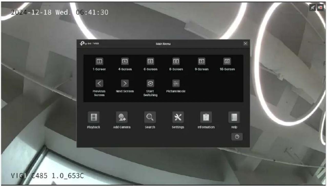
The NVR supports multiple layout modes, which display multiple screens in one page separately. To change the screen layout quickly, right-click on the Live View screen and click the buttons in Main Menu.



Click the corresponding buttons to change the number of displayed screens.
Click to jump to the previous/next page when the channels are more than the screens displayed in one page.
Click to enable/disable Switching. For example, 4 channels are displayed in Live View screen and 8 cameras are added to the NVR. When Switching is enabled, the NVR switches screens in Live View regularly to display the live view of 8 channels. To configure Switching Interval, click Settings and go to System > Basic Settings > Basic Settings.
For the layout mode with multiple screens, you can change the location of a channel by clicking and dragging it to another location. To view a channel in full screen, double-click it. Double-click it again to go back to multi-screen layout mode.

3.1.2 Merge Screens in Settings
In Settings, you can merge two screens into one large screen to improve the video display of dual-lens cameras like InSight S385DPS. Follow the steps below to merge screens.
- Right-click on the Live View screen and click Settings in the Main Menu. Go to System > Screen Layout.
- Select a layout mode below and the current layout displays. Each square indicates a region on the screen. Click a left screen, the (move right) icon will appear, and click this icon, the screen will be
merged to the right and turn into a larger one. Click Apply. If needed, you can also click the screen.


- Go to the Live View page, and you will see the video playing in the merged screen.

3.1.3 Rearrange Channels in Settings
In Settings, you can rearrange the channels in different layout modes more flexibly. Follow the steps below to rearrange the layout.
- Right-click on the Live View screen and click Settings in the Main Menu. Go to System > Screen Layout.
- Select a layout mode below and the current layout displays. Each square indicates a region on the screen. Click a square and click the checkbox of a channel to rearrange the channel in Live View. Click Apply.

3.2 Configure Live View Settings via Toolbar
Select a channel in Live View to reveal the toolbar. Click the following icons to configure Live View settings.

Click to view the playback of this channel. Click 5min Playback to view instant playback and History to search and view the recordings in Normal Playback, Tag Playback, and Event Playback. For detailed configuration, refer to Playback.

Click to zoom in/out the live image.

(Microphone needed and only for certain cameras) Click the icon and then Start Talk to talk. With this function, you can talk to people in the monitor area in real time.

(Only for certain cameras) Click and use the slide bar to adjust the volume.

(Only for the camera with Pan&Tilt) Click to enter the Preview of Pan&Tilt. You can adjust the camera location and call the presets. For details, refer to Preview Preset Settings.
 | Click to select the Live View strategy.Shortest Delay: Display the latest image with the shortest delay, which may lower the video fluency.Fluency: Display each frame to guarantee the fluency. The video may be delayed.Balanced: Display the video with a balance between timeliness and fluency. |
 | Displays the image resolution, HD or SD. |
 | (Only for certain cameras) Click to manually start the alarm. |
 | Hover your cursor to view the video information, including its channel, frame rate, bit rate, resolution, and encoding method. |
 | Click to hide the toolbar. |
3.3 Change Picture Mode
- Right-click on the Live View screen and click Picture Mode in the pop-up Main Menu.
- Select a mode to adjust the image. Click OK.


Recording and Storage
This chapter guides you on how to view and configure recording and storage settings on your NVR. VIGI NVR allows you to set your own recording schedules and parameters, assign disk quota to connected cameras, manage and detect the installed hard drive, as well as export and back up recordings. This chapter includes the following sections:
- Configure Recording Schedules
- Recording Controls
- Manage Hard Drive
- Expansion Storage (Only for some models)
- Long-term Storage (Only for some models)
- Backup Recordings
- Search
- Export Recordings
4.1 Configure Recording Schedules
The recording schedule section provides convenience and flexibility for the daily monitoring of your NVR. You can customize the recording schedule for all channels at a time or specify a recording schedule for certain channels. You can set different schedules for each day. In the Advanced Settings page, you can set the pre-recorded time and delay time for recording.
4.1.1 Customize Recording Schedule
The recording schedule in Storage enables users to customize the everyday recording plan for each channel according to their needs.
You can set all channels to record continuously (24/7), or set two cameras (Channel 1 and 2) to record based on a schedule of motion detection during a specified time and record continuously for the rest of time on weekdays; on weekends.
- Right-click on the Live View screen and click Settings in the pop-up main menu, then go to Storage > Recording Schedule > Basic Configuration.
- Select the channel from the drop-down list.
- Enable Schedule. By default, it is enabled.
- Customize the recording schedule with one of the following methods.
■ Method 1: Via Time Bar
1) Select ☑ Motion Detection Recording and drag the cursor on the time bar to set the time for motion detection recording from Monday to Friday. The color of these rectangles will change from blue to green. 2) Select ☑ Continuous Recording and drag the cursor to set the time for no recording on Saturday and Sunday. The color of these rectangles will be erased.
3) Click Save in Basic Configuration to save the settings.

■ Method 2: Via Edit Schedule
1) Click Edit Schedule.

2) Click + Add Schedule, select the recording type, and set the start time and end time.

Note:
- Make sure the periods for different recording types are not overlapped.
- The scheduled time can be accurate to the second.
3) Click Copy Schedule and select the repeating days for this schedule in a week, then click Yes.

4) Click Apply on the Edit Detailed Schedule page. 5) Click Apply in Basic Configuration to save the settings.
- Click Copy to and select the channel to apply the settings, then click Apply.

- Click Apply in Basic Configuration to save the settings.
4.1.2 Configure Advanced Recording Settings
To configure the pre-recorded and delay time for cameras, go to Storage > Recording Schedule > Advanced Settings. Click Save after you finish the configuration.

Pre-recorded Time
The time is set for cameras to record before the scheduled time or event. For example, the schedule for continuous recording starts at 10:00. If you set the pre-recorded time as 5 seconds, the camera starts to record at 9:59:55.
Note: It is recommended to remain the default setting of 5 seconds.
| Delay | The time is set for cameras to record after the scheduled time or event. For example, if you set the post-record time as 5 seconds, it records till 11:00:05 as motion detection ends at 11:00. | |
| Auto-Delete Files | Old | Enable this feature and set the maximum storage space. When the space of files reaches the set limit, the old files will be automatically deleted to store new files. |
4.2 Recording Controls
4.2.1 Configure Storage Disk Group
In Storage Disk Group, you can manually start and stop recording on certain channels, select the storage stream for recording, and select the hard drive group.
To configure these settings, Right-click on the Live View screen and click Settings in the pop-up main menu. Then go to Storage > Recording Controls and select Storage Disk Group. Click Save after you finish the configuration.

Channel Displays the name of camera in this channel.
Recording Switch Start/stop recording on the selected channel.
Record Audio Start/stop recording audio on the selected channel.
| Storage Stream | Select the stream for recording.Main Stream: : The video will be recorded in the main stream, with higher quality. The size of recording files will be larger when selected.Substream: The video will be recorded in the substream, with lower quality. The size of recording files will be smaller when selected.Both: The video will be recorded in both main stream and substream.Substream+Main Stream (Event): Generally, the video will be recorded in substream by default and the event video will be recorded in main stream. |
Storage Disk Group Select the disk group for the NVR with multiple hard drives.
4.2.2 Configure Disk Quota
In Disk Quota, you can manually start and stop recording on certain channels, select the stream for the storage of recordings, check the used capacity of hard drive on certain channels, and assign the disk quota to cameras to store recordings.
To configure these settings, right-click on the Live View screen and click Settings in the pop-up main menu. Then go to Storage > Recording Controls and select Disk Quota. Click Save after you finish the configuration.
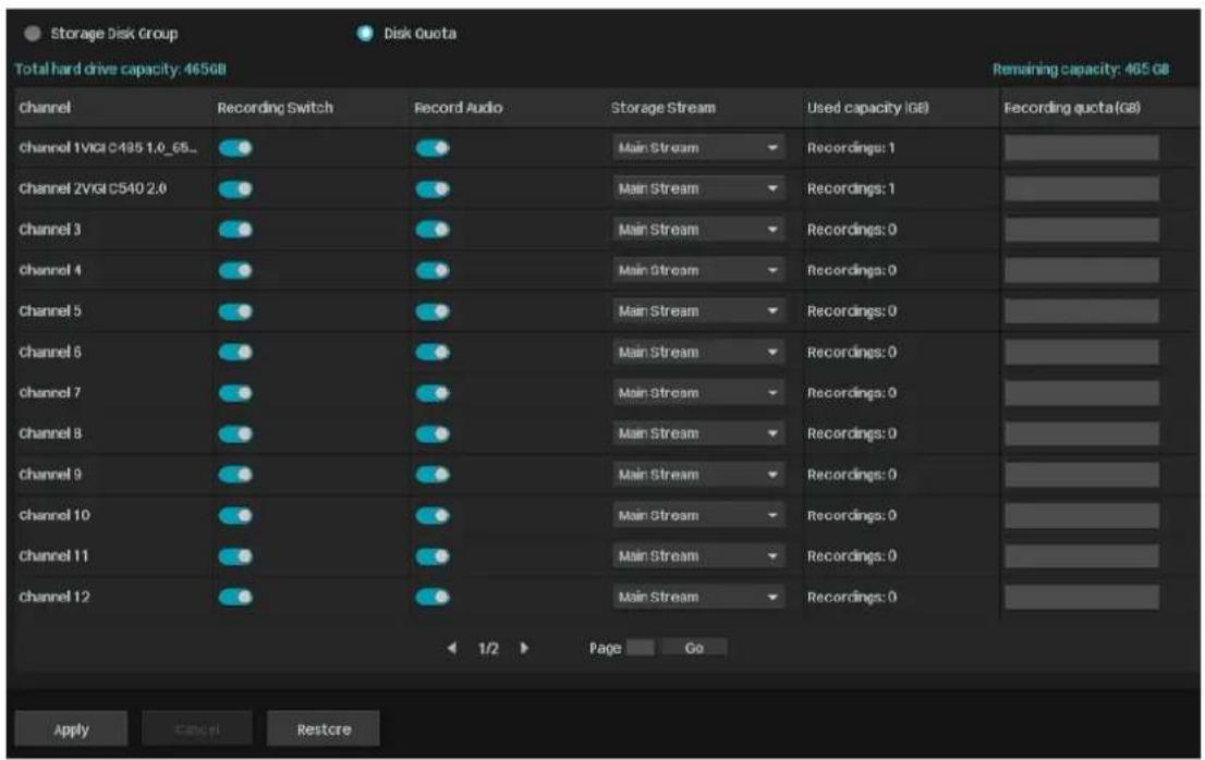
Channel: Displays the name of the camera on this channel.
Recording Switch: Start/stop recording on the selected channel.
Record Audio: Start/stop recording audio on the selected channel.
| Storage Stream | Select the stream for recording.Main Stream: The video will be recorded in the main stream, with higher quality. The size of recording files will be larger when selected.Substream: The video will be recorded in the substream, with lower quality. The size of recording files will be smaller when selected.Both: The video will be recorded in both main stream and substream.Substream+Main Stream (Event): Generally, the video will be recorded in substream by default and the event video will be recorded in main stream. |
| Used Capacity Displays the used space of hard drive for this channel. | |
| Recording Quota Assign the disk quota to your cameras for recording storage. | |

4.3 Manage Hard Drive
In Hard Drive Management, you can view and customize the settings of the hard drive, and choose different detection methods to check for bad sectors and the status of the installed hard drive.
4.3.1 View and Configure Settings of Hard Drive
In Hard Drive Management, you can view the parameters and configure the properties and disk group of the hard drive. You can also enable the NVR to overwrite earlier recording files when the hard drive is full.
To view and configure the settings of the hard drive, right-click on the Live View screen, click Settings in the pop-up main menu, then go to Storage > Hard Drive Management > Hard Drive Management. Click Save after you finish the configuration.
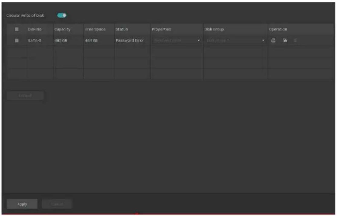
| Circular Write of Disk | Enable the NVR to overwrite the earlier recording files when the hard drive is full. |
| Disk No. Displays the number of hard drive. | |
| Capacity Displays the total space of hard drive. | |
| Free Space Displays the remaining storage capacity of hard drive. | |
| Status Displays the status of hard drive. | |
| Properties | Select the properties of hard drive. |
| Read-write: The data can be read and written on the hard drive. | |
| Read-only: The hard drive can only read data. | |
| Disk Group Select the disk group for the NVR with multiple hard drives. | |
| Operation | Click Format to format the hard drive. The data stored in the hard drive will be lost after you format it. |
| Click the Lock to verify the NVR encryption. | |
| Click the Delete button to remove the hard drive. | |
4.3.2 Add External Hard Drive to NVR
If you want to store more recordings on your NVR, add an external hard drive to expand its storage space.
Right-click on the Live View screen, click Settings in the pop-up main menu, then go to Storage > Hard Drive Management > Hard Drive Management. Click + and the hard drive will be automatically added to your NVR.
Note: The capacity of the external hard drive should exceed 120G.
4.3.3 Bad Sector Detection
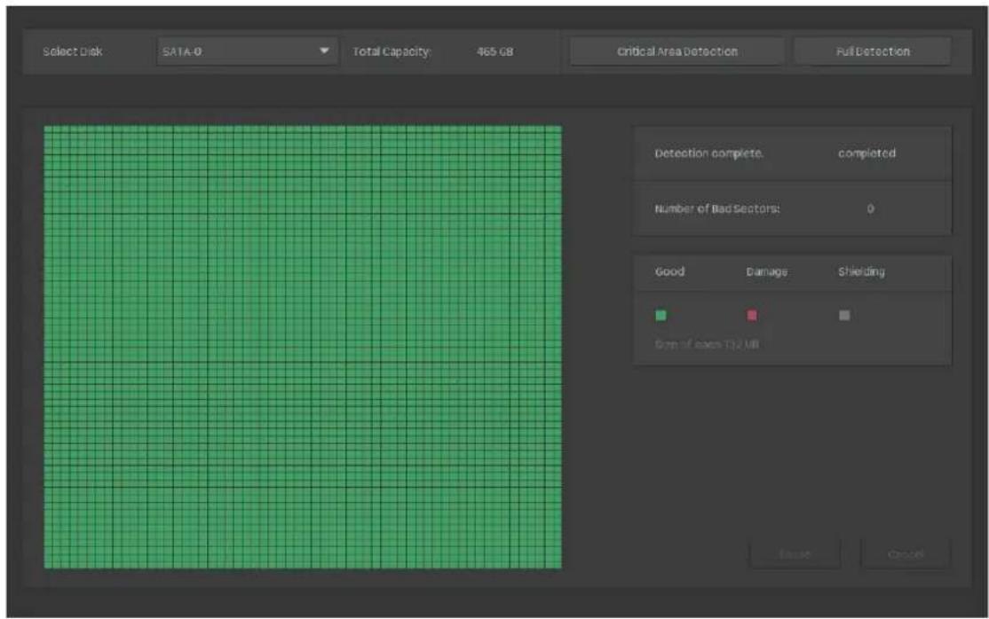
Bad sector detection conducts a check on the entire hard drive or its critical area, and displays the number of bad sectors on the hard drive. Follow the steps below to complete the bad sector detection.
- Right-click on the Live View screen and click Settings in the pop-up main menu.
- Go to Storage > Hard Drive Management > Bad Sector Detection.
- Select the hard drive and click Critical Area Detection or Full Detection at the top.
Different colors of the small blocks represent the good, damaged, and shielded sectors on your hard drive.
4.3.4 S.M.A.R.T Detection
S.M.A.R.T detection detects and reports various indicators of drive reliability and presents an overall assessment of the installed hard drive. Follow the steps below to complete the S.M.A.R.T detection.
- Right-click on the Live View screen and click Settings in the pop-up main menu.
- Go to Storage > Hard Drive Management > S.M.A.R.T Detection.
3. Select the disk and self-checking type.
Short: A scan of major components of the hard drive.
Extended: A complete surface scan of the drive.
Transmission: A scan of the mechanical parts of the hard drive detecting handling damages.
4. Click Start Detection on the right.

Temperature: Displays the operating temperature of the hard drive.
Use Time (day) Displays the usage time of the hard drive.
Self Assessment
Overall Assessment Displays the current status of the hard drive.
Attribute Name Displays the name of attributes concerning the health of hard drive.
Status Displays the status of these attributes.
Flags Displays the code of S.M.A.R.T ID.
| Threshold | Displays the threshold value of these attributes. Threshold marks the value at which the hard drive could fail. |
| Value | Displays the current value of these attributes. When it gets closer to the threshold, the hard drive is less likely to be healthy. |
| Worst | Displays the minimum values of these attributes. When Worst values are extremely lower than the current value, it indicates the hard drive errors or extreme working environment of the hard drive. |
Raw Value
Displays the data used for calculating Value.
4.4 Expansion Storage (Only for some models)
Expansion storage uses key frame storage technology to compress the earlier videos and release a large amount of storage space, and thus increases the recording time. After expansion storage is enabled, select the expansion type based on your needs.

High Expansion Extend the recording time to 3 times the original.
Moderate Expansion Extend the recording time to twice the original.
4.5 Long-term Storage (Only for some models)
Note:
If you have enabled Plug and Play, the long-term storage function cannot be enabled.
Long-term storage can reduce the size of recording files and extend the recording time by automatically changing the settings for recording and storage. To achieve this function, the VIGI NVR will adopt the following methods, including changing the smart coding type and bit rate type of camera, enabling expansion storage, after evaluating the hard drive capacity and the number of channels. After long-term storage is enabled, select the recording time you expect.

4.6 Backup Recordings
Backup allows you to copy all the recordings stored in your NVR to the external hard drive. You can view these recording files when installing the hard drive on another NVR.
Caution:
The data stored in your external hard drive will be lost if you choose to back up the recordings. It is recommended to back up the data in your external hard drive before you start the backup process.
To back up the recordings, follow the steps below:
- Right-click on the Live View screen and click Settings in the pop-up main menu.
- Go to Storage > Hard Drive Backup.
- Click Backup to start the backup process.

Note:
- You should prepare an external hard disk whose total space is larger than the used space of installed hard drive in NVR.
- If the free space of your external hard disk is not big enough for backing up recordings stored in NVR, click Initialize to format your hard drive first. The original data will be erased after initialization.

4.7 Search
Search allows you to search videos and search faces, people and vehicles appeared in the recordings stored.
Follow the steps below to configure the Search feature:
- Right-click on the Live View screen and click Settings in the pop-up Main Menu, then go to Search.

- Click the desired search type, video, face, people or vehicle. Select a channel, set the start time and end time, then click Search. You will see the search results displayed.

4.8 Export Recordings
You can export the recordings stored in the hard drive according to your needs. These recordings can be played on your media devices.
Follow the steps below:
- Prepare an external storage device and plug it into the USB slot of the NVR.
- Right-click on the Live View screen and click Settings in the pop-up Main Menu, then go to Search
- Click the desired search type. Select a channel, set the start time and end time, and click Yes.

- Click Advanced Time Filtering: Everyday Full Day and select the time span and repeated days of the week. Then click Yes.

- Select All for the recording type and All for the file type.
Locked Files will not be overwritten when loop recording is enabled.
Unlocked Files will be overwritten when loop recording is enabled.
All Display the locked and unlocked files.
- Click Search.
- Select the files you need and click Fast Export.
Note: The format of the audio in exported videos may be incompatible with some playback software.
- Select the folder or create a new folder and click Start Backup to export the files to your external storage device.


Playback
This function allows you to play the history recordings and edit them, such as adding tags and exporting clips. You can easily search the recordings based on the channel, date, tag, and event. This chapter contains the following sections:
- Instant Playback
- Play Normal Recordings
- Play Recordings with Tags
- Playback Recordings of Events
- Playback Operations
NVR supports the following four playback modes:
■ Instant Playback
Play the video of a single channel recorded in the last five minutes.
■ Normal Playback
Play the recordings of one day, including the continuous and event detection recordings.
Tag Playback
Play the recordings with tags added.
Event Playback
Play the recordings with events detected.
5.1 Instant Playback
You can replay the video recorded in the last five minutes via Instant Playback. Click a channel on Live View to reveal the toolbar. Click and then 5 min Playback to start instant playback.

5.2 Play Normal Recordings
Normal Recordings are video files from the continuous and event detection recordings. Follow the steps below to play normal recordings.
- Right-click on the Live View screen and click Playback in the pop-up Main Menu to open the Playback module.
- On the right panel, select Normal Playback, click the checkboxes to select channels, and select a date in the calendar. You can also click the checkboxes below to filter the recordings. Click Search.

- The recording files are listed both on the right panel and the time bar below. Double click a recording in the list or click to play the recordings. You can also click the to lock the recording. Once locked, the recording cannot be overridden when Loop Recording is enabled.

For more playback operations, refer to Playback Operations.
Note: When playing multiple channels, some channels may be unavailable due to limited resources. To watch the channels, click Back to deselect a few channels on the right panel and try again.
5.3 Play Recordings with Tags
Tags can be used to mark and search recordings. Follow the steps below to add tags and play recordings with tags.
■ Step 1: Add Tags to Recording Files
1) Right-click on the Live View screen and click Playback in the pop-up Main Menu to open the Playback module.

2) Select a time point in the recording listed in the time bar and click 📋 in the toolbar. The following window pops up. Enter the tag manually or select one from history tags. Click Yes.

■ Step 2: Search Tags
In the same module, select Tag Playback from the drop-down list on the right panel, click the checkboxes to select channels, and select a time range in the calendar. Click Search. You can enter a key word in the box to quickly search for the tagged recordings.

■ Step 3: Play the Recording File with a tag
The recording files with tags are listed on the right panel. Specify the time range before and after the tagged time point, then double click a recording in the list to play it.

You can also click ⋯ in the list and click Edit or Delete to edit the tag or delete it. For more playback operations, refer to Playback Operations.
5.4 Playback Recordings of Events
With Events configured, the NVR and cameras can detect and react to events. In Event Playback, you can search, play, and edit the videos recorded when events are detected.
Note: If you have never configured Events on the NVR, there are no recordings of events. To configure Events, refer to Events and Alerts.
Follow the steps below to search and play the recordings of certain events.
- Right-click on the Live View screen and click Playback in the pop-up Main Menu to open the Playback module.
- On the right panel, select Event Playback and select an event type and a filter type from the dropdown list. Click the checkboxes to select channels, and select a time range in the calendar. Click Search.

- The recording files of events are listed on the right panel. Double click a recording in the list to play it.

For more playback operations, refer to Playback Operations.
5.5 Playback Operations
In the Playback module, you can use the icons and buttons in the toolbar and on the right panel to adjust the display, edit and back up the recordings.
Note: The operations are not available in Instant Playback.
5.5.1 Basic Playback Operations
The following icons are supported when playing recordings:
 | Click to play/pause the video. |
 | Click to stop playing the recording. |
 | Select from the drop-down list to change the playing speed. |
 | Jump forward/backward by 30 seconds. |
 | (Available in a single screen and when the recording is paused) Play the recordings by frames. |
| [3Y06] | Click and slide to adjust the volume. |
| [X223] | Change the stream type of the current channel. You can select Auto to change the automatically change the stream type according to the video stored in the hard drive. If there is a main stream stored, the main stream video will be played first. If there is no main stream, it will switch to the sub-stream playback of the corresponding time. |
 | Change the stream type of all playback channels. You can select Auto to change the automatically change the stream type according to the video stored in the hard drive. If there is a main stream stored, the main stream video will be played first. If there is no main stream, it will switch to the sub-stream playback of the corresponding time. |
| [EYHZ] | Click to play the human detection event recordings. |
| [AYWH] | Click to play the vehicle detection event recordings. |
 | Enable Smart playback rules. By default, Play Event Recordings with 1x Playback Speed and play Non-event Recordings with 8x Playback Speed. You can change it as needed. |
| [28XX] | (Available in Normal Playback and Event Playback) Lock/unlock the recordings. Once locked, the recording cannot not be overridden when Loop Recording is enabled. |
| [6Y0Z] | (Available in Normal Playback and Event Playback) Add a tag to the recording. |
| [3ZZZ] | Click to edit the recordings. |
 | Click and select a channel to export its video clips. |
| [TCTZ] | Zoom in or out via Digital Zoom. |
 | Play the recordings in full screen. |
| Display Channel Number | Display/hide the channel number in Playback. |
| Hide Channel Number | |
 | Click to set the time span length. |
| CR: Continuous RecordingER: Event Recording | Select the recordings type. |
5.5.2 Set Smart Playback Rules
In Normal Playback, you can configure Smart Playback rules to adjust the playing speed automatically. This feature is only available when a single channel is playing. When Smart Playback is configured, the NVR can intelligently classify the recordings into two types, Event Recordings and Non-event Recordings, and adjusts the speed based on the recording types.
Click the icon and set the playing speed. You can skip Non-event Recordings by clicking the checkbox. Click Yes.

5.5.3 Edit Recordings
Follow the steps below to clip video files.
- In Playback, specify the playback mode, select a channel and time range, then click Search to search recordings.

- Click the recordings in the time bar to select a start time. Click the recordings and drag the mouse to adjust the length of the clip. Click to set the end of the clip.

After editing, you can click to view all clips. To export the clip to an external storage, select the clips and click Export.

Note:
• To export the clips, an external storage is required. - For the clips that are not exported, they will not be saved as new recordings when you leave the Playback module.
5.5.4 Export Recordings
In Playback, you can easily search the desired recordings based on channel, time, recording types, tags, and events, and back them up in batches. Follow the steps below to search and back up recordings.
Note: To back up the recordings, an external storage is required.
- In Playback, specify the playback mode, channels, and time range, then click Search to search recordings. The recording files are listed on the right panel. Click the checkbox to select the recordings to be exported and click Export Recordings.

- Specify the path to export the recordings. Click Export Recording and wait until backup is completed.

Events and Alerts
This chapter guides you on how to configure the event settings and alarm actions when your cameras detect different types of events. VIGI NVR monitors the user-defined areas and you'll be automatically alerted to any suspicious activity in your home and office. This chapter includes the following sections:
- Motion Detection
- Camera Tampering
- Scene Change Detection • Line Crossing Detection
- Intrusion Detection • Region Entering Detection • Region Exiting Detection
- Loitering Detection
- Object Abandoned/Removal Detection
- Vehicle Detection • Human Detection • Abnormal Sound Detection
- Smart Frame • VCA • Video Signal Loss Detection
- Offline and IP Conflict
- Disk Exception
- Login Exception
- Hardware Exception (Only for PoE models) • Fan Exception (Only for certain models)
- Alarm Device (Only for certain models)
- Disarming
- Alarm Server
6.1 Motion Detection
Motion detection allows cameras to detect the moving objects in the monitored area and triggers alarm actions. You can customize the motion detection settings, select the triggered actions and set the alarm schedule for cameras. Follow the steps below to finish the configuration.
- Right-click on the Live View screen and click Settings in the pop-up main menu, then go to Event > Basic Event > Motion Detection.

- Select the channel you want to detect and enable Motion Detection.
- Configure Area Settings. Draw areas for motion detection on the preview screen. The whole region is selected by default. Then configure the motion detection settings.
| Sensitivity | Adjust the value of sensitivity. A higher value can trigger alarm actions more easily. |
| Object Width Filter/Object Height Filter | Set the minimum object width/height to filter the corresponding events. |
| Detection | Select the detection type. It can be configured only for the cameras which support human detection and vehicle detection. |
| Smart Detection Confidence | Smart Detetcion Confidence can be set to low, medium and high. The function is available only for the cameras which support human detection and vehicle detection. |
- Click the Alarm Schedule tab and configure the alarm schedule. Click Apply.

- Click the Triggered Action tab and select the triggered action type and set the triggered actions according to your needs.
Normal Action

Screen Prompt
A warning sign

Live View screen.
Buzzer The buzzer on the NVR will beep when the motion is detected.
Pop-up Alarm Screen
The channel in Live View will be in full screen when the motion is detected.
Push Notifications The system will push notifications when the motion is detected.
Send Email The system will send an email when the motion is detected.
Highlight Window The channel window will be highlighted when the motion is detected.
Linkage Action
Channel Linkage
Select a linkage type and select the linkage channel.
Recording Linkage: The channels you select for recording linkage will start recording when the current channel detects motion.
Light Alarm: (Only supports camera models with light alarm) The camera will trigger a light alarm when motion is detected.
Audible Alarm: (Only supports camera models with audible alarm) The buzzer on the camera will alarm when motion is detected.
Alarm Output Linkage
AO1/AO2/AO3/AO4: When an event is triggered, the NVR will also be triggered.
Channel Alarm Output
Select the alarm output interface connected to the camera. When an event is triggered, the alarm output device connected to the camera will be triggered.
PTZ Linkage: When an event is triggered, the NVR or its connected cameras that support this feature will execute Preset or Patrols. Please configure the Preset and Patrol on the cameras.

- Click Apply to save the settings.
- (Optional) Click Copy to, and select the channels to which you want to apply the settings. Then click Apply to save the settings.

6.2 Camera Tampering
Camera tampering triggers alarm actions when an area of the camera's lens is purposely blocked, obstructed, or vandalized. You can customize the camera tampering settings and select the triggered actions. Follow the steps below to finish the configuration.
- Right-click on the Live View screen and click Settings in the pop-up main menu, then go to Event > Basic Event > Camera Tampering.
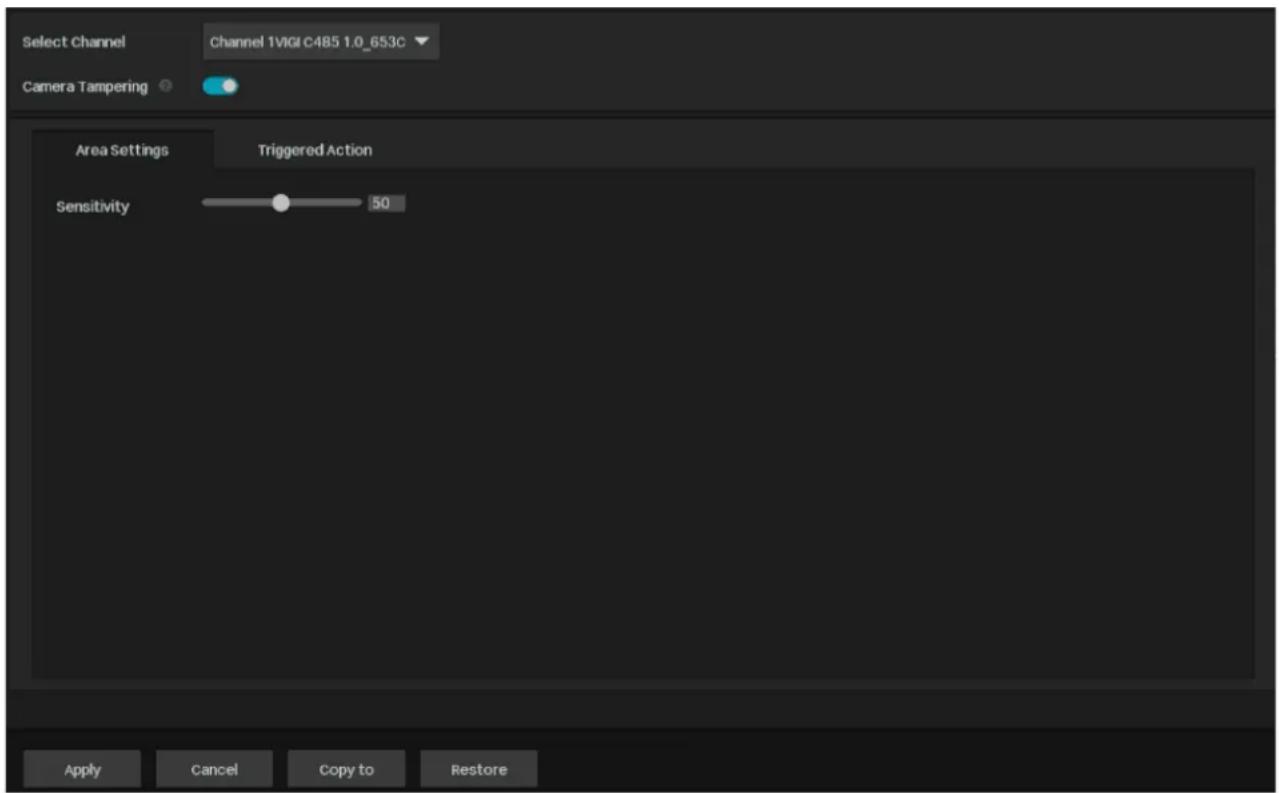
- Select the channel you want to detect and enable Camera Tampering.
- Set the sensitivity of camera tampering. A higher value can trigger the alarm actions more easily.
- Click the Triggered Action tab and select the triggered action type and set the triggered actions according to your needs.
Normal Action
Screen Prompt
A warning sign in the lower right corner of the monitor screen. Click it to check the event type and time.
Buzzer The buzzer on the NVR will beep when camera tampering is detected.
| Pop-up Alarm Screen | The channel in Live View will be in full screen when camera tampering is detected. |
| Push Notifications | The system will push notifications when camera tampering is detected. |
| Send Email The system will send an email when camera tampering is detected. | |
| Highlight Window | The channel window will be highlighted when camera tampering is detected. |
Linkage Action

| Channel Linkage | Select a linkage type and select the linkage channel.Recording Linkage: The channels you select for recording linkage will start recording when the current channel detects camera tampering.Light Alarm: (Only supports camera models with light alarm) The camera will trigger light alarm when camera tampering is detected.Audible Alarm: (Only supports camera models with audible alarm) The buzzer on the camera will alarm when camera tampering is detected. |
Alarm Output Linkage

AO1/AO2/AO3/AO4 When an event is triggered, the NVR will also be triggered.
| Channel Alarm Output | Select the alarm output interface connected to the camera. When an event is triggered, the alarm output device connected to the camera will be triggered. |
PTZ Linkage When an event is triggered, the NVR or its connected cameras that support this feature will execute Preset or Patrols. Please configure the Preset and Patrol on the cameras.
- Click Apply to save the settings.
- (Optional) Click Copy to, and select the channels to which you want to apply the settings. Then click Apply to save the settings.
6.3 Human Detection
Human detection triggers alarm actions when cameras detect persons are moving in the specified areas. You can customize the area settings, select the triggered actions and set the alarm schedule. Follow the steps below to finish the configuration.
- Right-click on the Live View screen and click Settings in the pop-up main menu, then go to Event > Smart Event > Human Detection.
- Select the channel you want to detect and enable Human Detection.
- Set the sensitivity of detection. A higher value can trigger the alarm actions more easily.
- Click the Alarm Schedule tab and configure the alarm schedule. Click Apply.

- Click the Triggered Action tab and select the triggered action type and set the triggered actions according to your needs.
Normal Action

| Screen Prompt | A warning sign [icon: A] the lower right corner of the monitor screen.Click it to check the event type and time. |
| Buzzer | The buzzer on the NVR will beep when cameras detect a human is moving in the specified areas. |
| Pop-up Alarm Screen | The channel in Live View will be in full screen when cameras detect a human is moving in the specified areas. |
| Push Notifications | The system will push notifications when cameras detect a human is moving in the specified areas. |
| Send Email | The system will send an email when cameras detect a human is moving in the specified areas. |
| Highlight Window | The channel window will be highlighted when cameras detect a human is moving in the specified areas. |
Linkage Action

| Select a linkage type and select the linkage channel. | |
| Recording Linkage: The channels you select for recording linkage will start recording when the current channel detects a human is moving in the specified areas. | |
| Channel Linkage | Light Alarm: (Only supports camera models with light alarm) The camera will trigger light alarm when the current channel detects a human is moving in the specified areas. |
| Audible Alarm: (Only supports camera models with audible alarm) The buzzer on the camera will alarm when the current channel detects a human is moving in the specified areas. |
Alarm Output Linkage
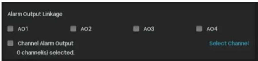
AO1/AO2/AO3/AO4 When an event is triggered, the NVR will also be triggered.
| Channel Alarm Output | Select the alarm output interface connected to the camera. When an event is triggered, the alarm output device connected to the camera will be triggered. |
PTZ Linkage When an event is triggered, the NVR or its connected cameras that support this feature will execute Preset or Patrols. Please configure the Preset and Patrol on the cameras.

6. Click Apply to save the settings.
- (Optional) Click Copy to, and select the channels to which you want to apply the settings. Then click Apply to save the settings.
6.4 Vehicle Detection
Vehicle detection triggers alarm actions when cameras detect vehicles moving in specified areas. You can customize the area settings, select the triggered actions, and set the alarm schedule. Follow the steps below to complete the configuration.
- Right-click on the Live View screen and click Settings in the pop-up main menu, then go to Event > Smart Event > Vehicle Detection.

- Select the channel you want to detect and enable Vehicle Detection.
- Set the sensitivity of detection. A higher value can trigger the alarm actions more easily.
- Click the Alarm Schedule tab and configure the alarm schedule. Click Apply.
- Click the Triggered Action tab and select the triggered action type and set the triggered actions according to your needs.
Normal Action
| Screen Prompt | A warning sign in the lower right corner of the monitor screen.Click it to check the event type and time. |
| Buzzer | The buzzer on the NVR will beep when cameras detect vehicles are moving in the specified areas. |
| Pop-up Alarm Screen | The channel in Live View will be in full screen when cameras detect vehicles are moving in the specified areas. |
| Push Notifications | The system will push notifications when cameras detect vehicles are moving in the specified areas. |
| Send Email | The system will send an email when cameras detect vehicles are moving in the specified areas. |
| Highlight Window | The channel window will be highlighted when cameras detect vehicles are moving in the specified areas. |
Linkage Action

| Select a linkage type and select the linkage channel. | |
| Recording Linkage: The channels you select for recording linkage will start recording when the current channel detects a human is moving in the specified areas. | |
| Channel Linkage | Light Alarm: (Only supports camera models with light alarm) The camera will trigger light alarm when the current channel detects a human is moving in the specified areas. |
| Audible Alarm: (Only supports camera models with audible alarm) The buzzer on the camera will alarm when the current channel detects a human is moving in the specified areas. |
Alarm Output Linkage

AO1/AO2/AO3/AO4 When an event is triggered, the NVR will also be triggered.
Channel Alarm Output Select the alarm output interface connected to the camera. When an event is triggered, the alarm output device connected to the camera will be triggered.
PTZ Linkage When an event is triggered, the NVR or its connected cameras that support this feature will execute Preset or Patrols. Please configure the Preset and Patrol on the cameras.

- Click Apply to save the settings.
- (Optional) Click Copy to, and select the channels to which you want to apply the settings. Then click Apply to save the settings.
6.5 Line Crossing Detection
Line crossing detection triggers alarm actions when cameras detect that moving objects cross a customized virtual line. You can customize the line crossing detection settings, select the triggered actions and set the alarm schedule. Follow the steps below to finish the configuration.
- Right-click on the Live View screen and click Settings in the pop-up main menu, then go to Event > Smart Event > Line Crossing Detection.

- Select the channel you want to detect and enable Line Crossing Detections.
- Configure the Area Settings. Draw lines on the preview screen. Select the line and configure settings of line crossing detection.
Note: The maximum number of customized lines is 4. If you want to apply the settings for different areas, select Sync Settings to All Lines.
| Sensitivity | Set the sensitivity of line crossing detection. A higher value can trigger alarm actions more easily.A->B: Only the object crossing the configured line from the A side to the B side can be detected. |
| Line Crossing Directions | B->A: Only the object crossing the configured line from the B side to the A side can be detected.A<->B: The object goes across the configured line with both directions can be detected. |
| Object Width Filter/ Object Height Filter | Set the minimum object width/height to filter the corresponding events. |
| Detection | Select the detection type. It can be configured only for the cameras which support human detection and vehicle detection. |
| Smart Detection Confidence | It can be set to low, medium and high. It can be configured only for the cameras which support human detection and vehicle detection. |
- Click the Alarm Schedule tab and configure the alarm schedule. Click Apply.

- Click the Triggered Action tab and select the triggered action type and set the triggered actions according to your needs.
Normal Action

Screen Prompt
A warning sign appears in the lower right corner of the monitor screen. Enable it to check the event type and time.
Chapter 6 Events and Alerts
| Buzzer | The buzzer on the NVR will beep when line crossing detection is triggered. |
| Pop-up Alarm Screen | The channel in Live View will be in full screen when line crossing detection is triggered. |
| Push Notifications | The system will push notifications when line crossing detection is triggered. |
| Send Email The system will send an email when line crossing detection is triggered. | |
| Highlight Window | The channel window will be highlighted when line crossing detection is triggered. |
Linkage Action

| Select a linkage type and select the linkage channel. | |
| Recording Linkage: The channels you select for recording linkage will start recording when line crossing detection is triggered. | |
| Channel Linkage | Light Alarm: (Only supports camera models with light alarm) The camera will trigger light alarm when line crossing detection is triggered. |
| Audible Alarm: (Only supports camera models with audible alarm) The buzzer on the camera will alarm when line crossing detection is triggered. |
Alarm Output Linkage
AO1/AO2/AO3/AO4 When an event is triggered, the NVR will also be triggered.
| Channel Alarm Output | Select the alarm output interface connected to the camera. When an event is triggered, the alarm output device connected to the camera will be triggered. |
PTZ Linkage When an event is triggered, the NVR or its connected cameras that support this feature will execute Preset or Patrols. Please configure the Preset and Patrol on the cameras.

- Click Apply to save the settings.
- (Optional) Click Copy to, and select the channels to which you want to apply the settings. Then click Apply to save the settings.
6.6 Intrusion Detection
Area intrusion triggers alarm actions when the NVR detects an intrusion in the specified areas. You can customize the area intrusion settings, select the triggered actions and set the alarm schedule. Follow the steps below to finish the configuration.
- Right-click on the Live View screen and click Settings in the pop-up main menu, then go to Event > Smart Event > Intrusion Detection.

- Select the channel you want to detect and enable Intrusion Detection.
- Draw intrusion areas on the preview screen. Select the area and configure the settings.
Note: The maximum number of customized areas is 4. If you want to apply the settings to different areas, select Sync Settings to All Areas.
Chapter 6 Events and Alerts
| Sensitivity | Adjust the value of sensitivity. A higher value can trigger alarm actions more easily. |
| Area Proportion | Set the proportion of the size of intrusive object to the intrusion area you have drawn. |
| Intrusion Time | Set the time for detecting the intrusion of objects. The interval should be no more than 10 seconds. |
| Object Width Filter/Object Height Filter | Set the minimum object width/height to filter the corresponding events. |
| Detection | Select the detection type. It can be configured only for the cameras which support human detection and vehicle detection. |
| Smart Detection Confidence | It can be set to low, medium and high. It can be configured only for the cameras which support human detection and vehicle detection. |
- Click the Alarm Schedule tab and configure the alarm schedule. Click Apply.

- Click the Triggered Action tab and select the triggered action type and set the triggered actions according to your needs.
Normal Action

Screen Prompt
A warning sign appears in the lower right corner of the monitor screen. Enable it to check the event type and time.
Chapter 6 Events and Alerts
| Buzzer The buzzer on the NVR will beep when intrusion detection is triggered. | |
| Pop-up Alarm Screen | The channel in Live View will be in full screen when intrusion detection is triggered. |
| Push Notifications | The system will push notifications when intrusion detection is triggered. |
| Send Email The system will send an email when intrusion detection is triggered. | |
| Highlight Window | The channel window will be highlighted when intrusion detection is triggered. |
Linkage Action

| Channel Linkage | Select a linkage type and select the linkage channel.Recording Linkage: The channels you select for recording linkage will start recording when intrusion detection is triggered.Light Alarm: (Only supports camera models with light alarm) The camera will trigger light alarm when intrusion detection is triggered.Audible Alarm: (Only supports camera models with audible alarm) The buzzer on the camera will alarm when intrusion detection is triggered. |
Alarm Output Linkage
AO1/AO2/AO3/AO4 When an event is triggered, the NVR will also be triggered.
| Channel Alarm Output | Select the alarm output interface connected to the camera. When an event is triggered, the alarm output device connected to the camera will be triggered. |
PTZ Linkage When an event is triggered, the NVR or its connected cameras that support this feature will execute Preset or Patrols. Please configure the Preset and Patrol on the cameras.

- Click Apply to save the settings.
- (Optional) Click Copy to, and select the channels to which you want to apply the settings. Then click Apply to save the settings.
6.7 Region Entering Detection
Region entering detection triggers alarm actions when cameras detect moving objects enter the specified regions. You can customize the region settings, select the triggered actions and set the alarm schedule. Follow the steps below to finish the configuration.
- Right-click on the Live View screen and click Settings in the pop-up main menu, then go to Event > Smart Event > Region Entering Detection.

- Select the channel you want to detect and enable Region Entering Detection.
- Draw protected areas on the preview screen. Select the area and configure the settings.
Note: The maximum number of customized areas is 4. If you want to apply the settings to different areas, select Sync Settings to All Areas.
Chapter 6 Events and Alerts
| Sensitivity | Adjust the value of sensitivity. A higher value can trigger alarm actions more easily. |
| Object Width Filter/Object Height Filter | Set the minimum object width/height to filter the corresponding events. |
| Detection | Select the detection type. It can be configured only for the cameras which support human detection and vehicle detection. |
| Smart Detection Confidence | It can be set to low, medium and high. It can be configured only for the cameras which support human detection and vehicle detection. |
- Click the Alarm Schedule tab and configure the alarm schedule. Click Apply.

- Click the Triggered Action tab and select the triggered action type and set the triggered actions according to your needs.
Normal Action

| Screen Prompt | A warning sign [IMAGE] the lower right corner of the monitor screen. Enable it to check the event type and time. |
| Buzzer | The buzzer on the NVR will beep when region entering detection is triggered. |
| Pop-up Alarm Screen | The channel in Live View will be in full screen when region entering detection is triggered. |
Chapter 6 Events and Alerts
| Push Notifications | The system will push notifications when region entering detection is triggered. |
| Send Email | The system will send an email when region entering detection is triggered. |
| Highlight Window | The channel window will be highlighted when region entering detection is triggered. |
Linkage Action

| Select a linkage type and select the linkage channel. | |
| Recording Linkage: The channels you select for recording linkage will start recording when region entering detection is triggered. | |
| Channel Linkage | Light Alarm: (Only supports camera models with light alarm) The camera will trigger light alarm when region entering detection is triggered. |
| Audible Alarm: (Only supports camera models with audible alarm) The buzzer on the camera will alarm when region entering detection is triggered. |
Alarm Output Linkage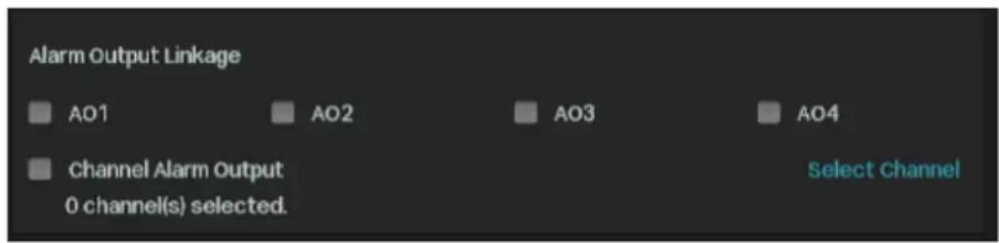
AO1/AO2/AO3/AO4 When an event is triggered, the NVR will also be triggered.
| Channel Alarm Output | Select the alarm output interface connected to the camera. When an event is triggered, the alarm output device connected to the camera will be triggered. |
PTZ Linkage When an event is triggered, the NVR or its connected cameras that support this feature will execute Preset or Patrols. Please configure the Preset and Patrol on the cameras.

- Click Apply to save the settings.
- (Optional) Click Copy to, and select the channels to which you want to apply the settings. Then click Apply to save the settings.
6.8 Region Exiting Detection
Region exiting detection triggers alarm actions when cameras detect moving objects exit the specified regions. You can customize the region settings, select the triggered actions and set the alarm schedule. Follow the steps below to finish the configuration.
- Right-click on the Live View screen and click Settings in the pop-up main menu, then go to Event > Smart Event > Region Exiting Detection.

- Select the channel you want to detect and enable Region Exiting Detection.
- Draw protected areas on the preview screen. Select the area and configure the settings.
Note: The maximum number of customized areas is 4. If you want to apply the settings to different areas, select Sync Settings to All Areas.
| Sensitivity | Adjust the value of sensitivity. A higher value can trigger alarm actions more easily. |
| Object Width Filter/Object Height Filter | Set the minimum object width/height to filter the corresponding events. |
| Detection | Select the detection type. It can be configured only for the cameras which support human detection and vehicle detection. |
| Smart Detection Confidence | It can be set to low, medium and high. It can be configured only for the cameras which support human detection and vehicle detection. |
- Click the Alarm Schedule tab and configure the alarm schedule. Click Apply.

- Click the Triggered Action tab and select the triggered action type and set the triggered actions according to your needs.
Normal Action

| Screen Prompt | A warning sign [IMAGE] the lower right corner of the monitor screen. Enable it to check the event type and time. |
| Buzzer | The buzzer on the NVR will beep when region exiting detection is triggered. |
| Pop-up Alarm Screen | The channel in Live View will be in full screen when region exiting detection is triggered. |
| Push Notifications | The system will push notifications when region exiting detection is triggered. |
| Send Email The system will send an email when region exiting detection is triggered. | |
| Highlight Window | The channel window will be highlighted when region exiting detection is triggered. |
| Linkage Action | |

| Select a linkage type and select the linkage channel. | |
| Recording Linkage: The channels you select for recording linkage will start recording when region exiting detection is triggered. | |
| Channel Linkage | Light Alarm: (Only supports camera models with light alarm) The camera will trigger light alarm when region exiting detection is triggered. |
| Audible Alarm: (Only supports camera models with audible alarm) The buzzer on the camera will alarm when region exiting detection is triggered. |
Alarm Output Linkage
| AO1/AO2/AO3/AO4 When an event is triggered, the NVR will also be triggered. | |
| Channel Alarm Output | Select the alarm output interface connected to the camera. When an event is triggered, the alarm output device connected to the camera will be triggered. |
PTZ Linkage When an event is triggered, the NVR or its connected cameras that support this feature will execute Preset or Patrols. Please configure the Preset and Patrol on the cameras.

- Click Apply to save the settings.
- (Optional) Click Copy to, and select the channels to which you want to apply the settings. Then click Apply to save the settings.
6.9 Loitering Detection
Alarm actions will be triggered when the camera detects a suspicious individual loitering in an area for some time. You can customize the area settings, select the triggered actions, and set the alarm schedule. Follow the steps below to finish the configuration.
- Right-click on the Live View screen and click Settings in the pop-up main menu, then go to Event > Smart Event > Loitering Detection.

- Select the channel you want to detect and enable Loitering Detection.
- Draw areas on the preview screen. Select the area and configure the settings.
Note: The maximum number of customized areas is 4. If you want to apply the settings to different areas, select Sync Settings to All Areas.
| Sensitivity | Adjust the value of sensitivity. A higher value can trigger alarm actions more easily. |
| Loitering Time Set the time a suspicious individual lingers in an area. | |
| Object Width Filter/Object Height Filter | Set the minimum object width/height to filter the corresponding events. |
| Detection | Select the detection type. It can be configured only for the cameras which support human detection and vehicle detection. |
| Smart Detection Confidence | It can be set to low, medium and high. It can be configured only for the cameras which support human detection and vehicle detection. |
- Click the Alarm Schedule tab and configure the alarm schedule. Click Apply.

- Click the Triggered Action tab and select the triggered action type and set the triggered actions according to your needs.
Normal Action

Screen Prompt
A warning sign ⚠️ appears in the lower right corner of the monitor screen. Enable it to check the event type and time.
Buzzer: The buzzer on the NVR will beep when loitering detection is triggered.
| Pop-up Alarm Screen | The channel in Live View will be in full screen when loitering detection is triggered. |
| Push Notifications | The system will push notifications when loitering detection is triggered. |
| Send Email The system will send an email when loitering detection is triggered. | |
| Highlight Window | The channel window will be highlighted when loitering detection is triggered. |
Linkage Action

| Channel Linkage | Select a linkage type and select the linkage channel.Recording Linkage: The channels you select for recording linkage will start recording when loitering detection is triggered.Light Alarm: (Only supports camera models with light alarm) The camera will trigger light alarm when loitering detection is triggered.Audible Alarm: (Only supports camera models with audible alarm) The buzzer on the camera will alarm when loitering detection is triggered. |
Alarm Output Linkage

AO1/AO2/AO3/AO4: When an event is triggered, the NVR will also be triggered.
| Channel Alarm Output | Select the alarm output interface connected to the camera. When an event is triggered, the alarm output device connected to the camera will be triggered. |
PTZ Linkage When an event is triggered, the NVR or its connected cameras that support this feature will execute Preset or Patrols. Please configure the Preset and Patrol on the cameras.

- Click Apply to save the settings.
- (Optional) Click Copy to, and select the channels to which you want to apply the settings. Then click Apply to save the settings.
6.10 Object Abandoned/Removal Detection
Object abandoned/removal detection triggers alarm actions when cameras detect objects are left behind or taken away in the specified areas. You can customize the area settings, select the triggered actions and set the alarm schedule. Follow the steps below to finish the configuration.
- Right-click on the Live View screen and click Settings in the pop-up main menu, then go to Event > Smart Event > Object Abandoned/Removal Detection.

- Select the channel you want to detect and enable Object Abandoned/Removal Detection.
- Draw areas on the preview screen. Select the area and configure the settings.
Note: The maximum number of customized areas is 4. If you want to apply the settings to different areas, select Sync Settings to All Areas.
| Sensitivity | Adjust the value of sensitivity. A higher value can trigger alarm actions more easily. |
| Detection Type Select the detection type. | |
| Time Threshold | Set how long the object is left behind or taken away to trigger the event. |
| Object Width Filter/Object Height Filter | Set the minimum object width/height to filter the corresponding events. |
- Click the Alarm Schedule tab and configure the alarm schedule. Click Apply.

- Click the Triggered Action tab and select the triggered action type and set the triggered actions according to your needs.
Normal Action

| Screen Prompt | A warning sign [icon: A] the lower right corner of the monitor screen. Enable it to check the event type and time. |
| Buzzer | The buzzer on the NVR will beep when the camera detects objects are left behind or taken away in the specified areas. |
| Pop-up Alarm Screen | The channel in Live View will be in full screen when the camera detects objects are left behind or taken away in the specified areas. |
| Push Notifications | The system will push notifications when the camera detects objects are left behind or taken away in the specified areas. |
| Send Email | The system will send an email when the camera detects objects are left behind or taken away in the specified areas. |
| Highlight Window | The channel window will be highlighted when the camera detects objects are left behind or taken away in the specified areas. |
Linkage Action

| Select a linkage type and select the linkage channel. | |
| Recording Linkage: The channels you select for recording linkage will start recording when the camera detects objects are left behind or taken away in the specified areas. | |
| Channel Linkage | Light Alarm: (Only supports camera models with light alarm) The camera will trigger light alarm when the camera detects objects are left behind or taken away in the specified areas. |
| Audible Alarm: (Only supports camera models with audible alarm) The buzzer on the camera will alarm when the camera detects objects are left behind or taken away in the specified areas. |
Alarm Output Linkage
AO1/AO2/AO3/AO4 When an event is triggered, the NVR will also be triggered.
| Channel Alarm Output | Select the alarm output interface connected to the camera. When an event is triggered, the alarm output device connected to the camera will be triggered. |
PTZ Linkage When an event is triggered, the NVR or its connected cameras that support this feature will execute Preset or Patrols. Please configure the Preset and Patrol on the cameras.

- Click Apply to save the settings.
- (Optional) Click Copy to, and select the channels to which you want to apply the settings. Then click Save to save the settings.
6.11 Scene Change Detection
Scene change detection triggers alarm actions when the viewing direction of camera's lens is purposely changed. You can enable this feature, select the triggered actions and set the alarm schedule for cameras. Follow the steps below to finish the configuration.
- Right-click on the Live View screen and click Settings in the pop-up main menu, then go to Event > Smart Event > Scene Change Detection.

- Select the channel you want to detect and enable Scene Change Detection.
- Set the sensitivity of detection. A higher value can trigger the alarm actions more easily.
- Click the Alarm Schedule tab and configure the alarm schedule. Click Apply.
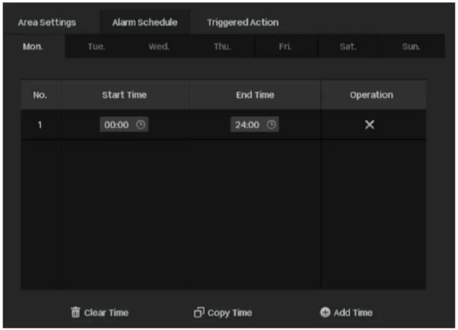
- Click the Triggered Action tab and select the triggered action type and set the triggered actions according to your needs.
Normal Action

| Screen Prompt | A warning sign [icon: the lower right corner of the monitor screen. Click it to check the event type and time. |
| Buzzer | The buzzer on the NVR will beep when the camera detects the viewing direction is changed. |
| Pop-up Alarm Screen | The channel in Live View will be in full screen when the camera detects the viewing direction is changed. |
| Push Notifications | The system will push notifications when the camera detects the viewing direction is changed. |
| Send Email | The system will send an email when the camera detects the viewing direction is changed. |
| Highlight Window | The channel window will be highlighted when the camera detects the viewing direction is changed. |
Linkage Action

| Select a linkage type and select the linkage channel. | |
| Recording Linkage: The channels you select for recording linkage will start recording when the current channel detects the viewing direction is changed. | |
| Channel Linkage | Light Alarm: (Only supports camera models with light alarm) The camera will trigger light alarm when it detects the viewing direction is changed. |
| Audible Alarm: (Only supports camera models with audible alarm) The buzzer on the camera will alarm when the current channel detects the viewing direction is changed. |
Alarm Output Linkage

AO1/AO2/AO3/AO4: When an event is triggered, the NVR will also be triggered.
| Channel Alarm Output | Select the alarm output interface connected to the camera. When an event is triggered, the alarm output device connected to the camera will be triggered. |
PTZ Linkage: When an event is triggered, the NVR or its connected cameras that support this feature will execute Preset or Patrols. Please configure the Preset and Patrol on the cameras.

- Click Apply to save the settings.
- (Optional) Click Copy to, and select the channels to which you want to apply the settings. Then click Apply to save the settings.
6.12 Abnormal Sound Detection
Abnormal sound triggers alarm actions when cameras detect an abnormal sound. You can select the triggered actions and set the alarm schedule. Follow the steps below to finish the configuration.
- Right-click on the Live View screen and click Settings in the pop-up main menu, then go to Event > Smart Event > Abnormal Sound Detection.
- Select the channel you want to detect and enable Abnormal Sound Detection.
- Set the sensitivity of detection. A higher value can trigger the alarm actions more easily.
- Set the alert threshold to trigger the action. A lower value can trigger the alarm actions more easily.
- Click the Alarm Schedule tab and configure the alarm schedule. Click Apply.

- Click the Triggered Action tab and select the triggered action type and set the triggered actions according to your needs.
Normal Action

| Screen Prompt | A warning sign [icon: the lower right corner of the monitor screen. Click it to check the event type and time. |
| Buzzer | The buzzer on the NVR will beep when the camera detects an abnormal sound. |
| Pop-up Alarm Screen | The channel in Live View will be in full screen when the camera detects an abnormal sound. |
| Push Notifications | The system will push notifications when the camera detects an abnormal sound. |
| Send Email | The system will send an email when the camera detects an abnormal sound. |
| Highlight Window | The channel window will be highlighted when the camera detects an abnormal sound. |
Channel Linkage
Select a linkage type and select the linkage channel.
Recording Linkage: The channels you select for recording linkage will start recording when the current channel detects an abnormal sound.
Light Alarm: (Only supports camera models with light alarm) The camera will trigger light alarm when an abnormal sound is detected.
Audible Alarm: (Only supports camera models with audible alarm) The buzzer on the camera will alarm when an abnormal sound is detected.
Alarm Output Linkage
AO1/AO2/AO3/AO4 When an event is triggered, the NVR will also be triggered.
Channel Alarm Output
Select the alarm output interface connected to the camera. When an event is triggered, the alarm output device connected to the camera will be triggered.
PTZ Linkage When an event is triggered, the NVR or its connected cameras that support this feature will execute Preset or Patrols. Please configure the Preset and Patrol on the cameras.
- Click Apply to save the settings.
- (Optional) Click Copy to, and select the channels to which you want to apply the settings. Then click Apply to save the settings.
6.13 Queue Detection
You will be notified when an abnormal queue size or an abnormal queue wait time is detected in the detection area. You can select the triggered actions and set the alarm schedule. Follow the steps below to finish the configuration.
- Right-click on the Live View screen and click Settings in the pop-up main menu, then go to Event > Smart Event > Queue Detection.

- Select the channel you want to detect and enable Queue Detection.
- Draw a polygon in the preview area and set the sensitivity of detection. A higher value can trigger the alarm actions more easily.
- Set the Alert Method to trigger the action. You can set the Queue Size Threshold and Wait Time Limit as needed.
- Click the Alarm Schedule tab and configure the alarm schedule. Click Apply.
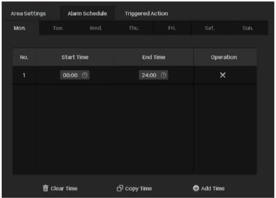
- Click the Triggered Action tab and select the triggered action type and set the triggered actions according to your needs.
Normal Action

| Screen Prompt | A warning sign the lower right corner of the monitor screen.Click it to check the event type and time. |
| Buzzer The buzzer on the NVR will beep when an queue detection is triggered. | |
| Pop-up Alarm Screen | The channel in Live View will be in full screen when an queue detection is triggered. |
| Push Notifications | The system will push notifications when an queue detection is triggered. |
| Send Email The system will send an email when an queue detection is triggered. | |
| Highlight Window | The channel window will be highlighted when an queue detection is triggered. |
Linkage Action

Channel Linkage
Select a linkage type and select the linkage channel.
Recording Linkage: The channels you select for recording linkage will start recording when a queue detection is triggered.
Light Alarm: (Only supports camera models with light alarm) The camera will trigger a light alarm when a queue detection is triggered.
Audible Alarm: (Only supports camera models with audible alarm) The buzzer on the camera will sound an alarm when a queue detection is triggered.
Alarm Output Linkage

AO1/AO2/AO3/AO4
Select the alarm output interface connected to the camera. When an event is triggered, the alarm output device connected to the camera will be triggered.
Channel Alarm Output
When an event is triggered, the NVR will also be triggered.
PTZ Linkage: When an event is triggered, the NVR or its connected cameras that support this feature will execute Preset or Patrols. Please configure the Preset and Patrol on the cameras.

- Click Apply to save the settings.
6.14 Smart Frame
With Smart Frame, when the camera detects a moving target (motion, vehicle, and human figure), it will use a frame to highlight the moving target on the screen. Follow the steps below to finish the configuration.
- Right-click on the Live View screen and click Settings in the pop-up main menu, then go to Event > Smart Frame.

- Click IPC Smart Frame/NVR Smart Frame, select the device you want to enable Smart Frame.
- Enable Smart Frame for the desired detection.
- Click Apply to save the settings.
- (Optional) Click Copy to, and select the channels to which you want to apply the settings. Then click Apply to save the settings.
6.15 VCA
You can go to the VCA module to configure Face Analysis or Object Attribute Analysis. Please note that you can only enable one analysis at a time. Face analysis can be used to analyze the faces that appear on the screen, and object attribute analysis can be used to identify human and vehicle attributes. Follow the steps below to finish the configuration.
Chapter 6 Events and Alerts
- Right-click on the Live View screen and click Settings in the pop-up main menu, then go to Event > VCA > Global Configuration.

- Enable Smart Analysis (Beta) on NVR and check I confirm that I have fully read and understood the Privacy Policy, then click Apply.
- Go to Event > VCA > Smart Analysis. For Face Analysis, check I confirm that I have fully read and understood the Privacy Policy.

- Select the channel you want to detect and select the analysis type. Click Apply.
1. Go to Event > VCA > Face Analysis.

2. Enable Face Analysis and set the Alarm Schedule.

3. Click Apply to save the settings.
- Go to Event > VCA > Object Attribute Analysis.

- Enable the attribute types and click Apply to save the settings.
6.16 Video Signal Loss Detection
Alarm actions will be triggered when the NVR cannot get video signal from the camera and display signal on the Live View screen. You can customize the triggered actions for different cameras. Follow the steps below to finish the configuration.
Chapter 6 Events and Alerts
- Right-click on the Live View screen and click Settings in the pop-up main menu, then go to Event > Exception Detection > Video Signal Loss.

The alarm actions are as follows:
| Screen Prompt | A warning sign the lower right corner of the monitor screen. Enable it to check the event type and time. |
| Pop Alarm Screen | The channel in Live View will be in full screen when the NVR detects the signal loss. |
| Buzzer The buzzer on the NVR will beep when the NVR detects the signal loss. | |
| Send Email The system will send an email when the NVR detects the signal loss. | |
| Recording Linkage | Select the channel and select the camera. The cameras you select for recording linkage will start recording when the current channel detects the signal loss. |
| Alarm Output Linkage | Select the channel and select the alarm output interface connected to the camera. When an exception is detected, the alarm output device connected to the camera will be triggered. |
- Click Apply to save the settings.

6.17 Offline and IP Conflict
You can select triggered actions for these exception types (NVR offline, NVR IP conflict, IPC IP conflict, and IP address obtained from DHCP conflicts with the internal IP). Follow the steps below to finish the configuration.
- Right-click on the Live View screen and click Settings in the pop-up main menu, then go to Event > Exception Detection > Offline and IP Conflict.
| Exception Type | Operation | ||||
| NVR offline | ✓ Screen Prompt Buzzer Send Email Alarm Output Linkage Select All AO1 AO2 AO3 AO4 | ||||
| NVR IP Conflict | ✓ Screen Prompt Buzzer Send Email Alarm Output Linkage Select All AO1 AO2 AO3 AO4 | ||||
| IPC IP Conflict | ✓ Screen Prompt Buzzer Send Email Alarm Output Linkage Select All AO1 AO2 AO3 AO4 | ||||
| The IP address obtained from DHCP conflicts with the in... | ✓ Screen Prompt Buzzer Send Email Alarm Output Linkage Select All AO1 AO2 AO3 AO4 | ||||
| Apply Cancel Restore | |||||
- Select the alarm actions according to your needs:
| Screen Prompt | A warning sign in the lower right corner of the monitor screen. Enable it to check the event type and time. |
| Buzzer | The buzzer on the NVR will beep when NVR is offline or IP conflict is detected. |
| Send Email | (Only for IPC IP Conflict exception type)The system will send an email when IPC IP conflict is detected. |
| Alarm Output Linkage | Select the alarm output interface connected to the camera. When an exception is detected, the alarm output device connected to the camera will be triggered. |
- Click Apply to save the settings.
6.18 Disk Exception
Alarm actions will be triggered when the NVR detects disk problems. You can select triggered actions for the exception types (No disk, Hard drive exception, Hard drive reallocated section and count error, No enough space of hard drive, Hard drive password error). Follow the steps below to finish the configuration.
- Right-click on the Live View screen and click Settings in the pop-up main menu, then go to Event > Exception Detection > Disk Exception.

- Select the alarm actions according to your needs:
| Screen Prompt | A warning sign in the lower right corner of the monitor screen. Enable it to check the event type and time. |
| Buzzer The buzzer on the NVR will beep when disk problems are detected. | |
| Send Email The system will send an email when disk problems are detected. | |
| Alarm Output Linkage | Select the alarm output interface connected to the camera. When an exception is detected, the alarm output device connected to the camera will be triggered. |
- Click Apply to save the settings.
6.19 Login Exception
Login limitation sets the maximum login attempts to protect the security of your NVR. The NVR will be locked for 30 minutes if you enter the wrong password more than the specified attempts. You can set the buzzer to alarm after the maximum login attempts is exceeded. Follow the steps below to finish the configuration.
- Right-click on the Live View screen and click Settings in the pop-up main menu, then go to Event > Exception Detection > Login Exception.

- Enable Login Limitation to limit the login attempts.
- Set the maximum login attempts. The number should be between 3 and 10.
- (Optional) Enable Buzzer or Send Email if you want the buzzer to alarm or the system sends an email after the maximum login attempts are exceeded. Select the alarm output interface connected to the camera. When an exception is detected, the alarm output device connected to the camera will be triggered.
- Click Apply to save the settings.
Note: To unlock the NVR and try to log in again, power the NVR off then power it on.
6.20 Hardware Exception (Only for PoE models)
Alarm actions will be triggered when the NVR detects hardware problems. You can select triggered actions for the exception types (Single port short circuit, Single port power exceeded, PSE chip temperature is too high, and Total power exceeded). Follow the steps below to finish the configuration.
- Right-click on the Live View screen and click Settings in the pop-up main menu, then go to Event > Exception Detection > Hardware Exception.
| Something wrong with the hardware | |||
| Exception Type | Operation | ||
| Single port short circuit | ✓ Screen Prompt ✓ Buzzer ✓ Send Email Alarm Output Linkage ■ Select All □ AO1 □ AO2 □ AO3 □ AO4 | ||
| Single port power exceeded. | ✓ Screen Prompt ✓ Buzzer ✓ Send Email Alarm Output Linkage ■ Select All □ AO1 □ AO2 □ AO3 □ AO4 | ||
| pse chip temperature is too high. | ✓ Screen Prompt ✓ Buzzer ✓ Send Email Alarm Output Linkage ■ Select All □ AO1 □ AO2 □ AO3 □ AO4 | ||
| Total power exceeded. | ✓ Screen Prompt ✓ Buzzer ✓ Send Email Alarm Output Linkage ■ Select All □ AO1 □ AO2 □ AO3 □ AO4 | ||
- Select the alarm actions according to your needs:
| Screen Prompt | A warning sign in the lower right corner of the monitor screen. Enable it to check the event type and time. |
| Buzzer The buzzer on the NVR will beep when hardware problems are detected. | |
| Send Email The system will send an email when hardware problems are detected. | |
| Alarm Output Linkage | Select the alarm output interface connected to the camera. When an exception is detected, the alarm output device connected to the camera will be triggered. |
- Click Apply to save the settings.

6.21 FTP Backup Exception (Only for Certain models)
Alarm actions will be triggered when the NVR detects FTP backup problems. You can select triggered actions for this exception type. Follow the steps below to finish the configuration.
- Right-click on the Live View screen and click Settings in the pop-up main menu, then go to Event > Exception Detection > FTP Backup Exception.
| FTP Backup Exception | |
| Exception Type | Operation |
| FTP Directory Storage Space Insufficient | ✓ Screen Prompt ✓ Buzzer Alarm Output Linkage Select All AO1 AO2 AO3 AO4 |
- Select the alarm actions according to your needs:
| Screen Prompt | A warning sign in the lower right corner of the monitor screen. Enable it to check the event type and time. |
| Buzzer The buzzer on the NVR will beep when hardware problems are detected. | |
| Alarm Output Linkage | Select the alarm output interface connected to the camera. When an exception is detected, the alarm output device connected to the camera will be triggered. |
- Click Apply to save the settings.

6.22 Fan Exception (Only for certain models)
Alarm actions will be triggered when the NVR detects fan problems. You can select triggered actions. Follow the steps below to finish the configuration.
- Right-click on the Live View screen and click Settings in the pop-up main menu, then go to Event > Exception Detection > Fan Exception.
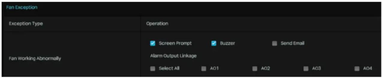
- Select the alarm actions according to your needs:
| Screen Prompt | A warning sign in the lower right corner of the monitor screen. Enable it to check the event type and time. |
| Buzzer The buzzer on the NVR will beep when fan problems are detected. | |
| Send Email The system will send an email when fan problems are detected. | |
| Alarm Output Linkage | Select the alarm output interface connected to the camera. When an exception is detected, the alarm output device connected to the camera will be triggered. |
- Click Apply to save the settings.
6.23 Alarm Device (Only for certain models)
Some VIGI NVRs support external alarm devices, which can be used to trigger alarms after NVR events, or to detect environmental abnormalities and provide abnormal signals. Connect your alarm device to the alarm interface.


- Go to Event > Alarm Device > Alarm Input to load the following page.

- You can modify the Alarm Name for the port as needed.
- Set the alarm Type, Normally Closed or Normally Open. Normally Open means that under normal conditions, the circuit is open and no current passes through the NVR; when the alarm is triggered, the current passes through the NVR and the NVR alarms. Normally Closed means that normally the circuit is closed, and the NVR will alarm in case of a circuit fault or alarm trigger. This depends on the type of alarm input device.
- Enable this alarm input.
Chapter 6 Events and Alerts
- Click the Action button to configure the arming time and linkage method, then the Alarm input will only work during the set time period. You can click Edit to add time and quickly copy time to other days, click Confirm to save the time settings.

- Click Linkage Method to configure the linkage method.
Normal Action

Screen Prompt
A warning sign appears in the lower right corner of the monitor screen. Click it to check the event type and time.
Buzzer: The buzzer on the NVR will beep when the alarm is triggered.
Pop-up Alarm Screen
The channel in Live View will be in full screen when the alarm is triggered.
Push Notifications: The system will push notifications when the alarm is triggered.
Send Email: The system will send an email when the alarm is triggered.
Highlight Window: The channel window will be highlighted when the alarm is triggered.
Linkage Action

Channel Linkage
Select a linkage type and select the linkage channel.
Recording Linkage: The channels you select for recording linkage will start recording when the alarm is triggered.
Light Alarm: (Only supports camera models with light alarm) The camera will trigger light alarm when the alarm is triggered.
Audible Alarm: (Only supports camera models with audible alarm) The buzzer on the camera will alarm when the alarm is triggered.
Alarm Output Linkage

AO1/AO2/AO3/AO4
Select the alarm output interface connected to the camera. When an event is triggered, the alarm output device connected to the camera will be triggered.
Channel Alarm Output
When an event is triggered, the NVR will also be triggered
PTZ Linkage When an event is triggered, the NVR or its connected cameras that support this feature will execute Preset or Patrols. Please configure the Preset and Patrol on the cameras.

- Alarm Output.
- Go to Event > Alarm Device > Alarm Output to load the following page.
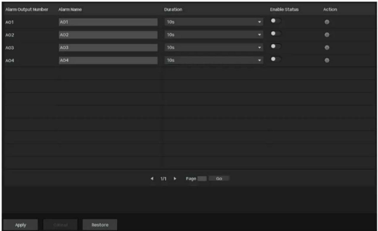
- You can modify the Alarm Name for the port as needed.
- Set the Duration to specify how long the alarm will last.
- Enable this alarm output.
- Click the Action button to configure the arming time, then the Alarm output will only work during the set time period. You can click Edit to add time and quickly copy time to other days, click Confirm to save the time settings.

- Click Apply to save the settings.

6.24 Disarming
If you don't want to be bothered by the linkage actions triggered by events, you can enable the Disarming feature to disable all or specific linkage actions. Follow the steps below to finish the configuration.
- Right-click on the Live View screen and click Settings in the pop-up main menu, then go to Event > Disarming.

- Enable Disarming and select the linkage actions you don't want to be notified about.
| All All actions will be selected. | |
| Buzzer The buzzer on the NVR will beep when an event is triggered. | |
| Screen Prompt | A warning sign in the lower right corner of the monitor screen. Enable it to check the event type and time. |
| Pop-up Alarm Screen | The channel in Live View will be in full screen when an event is triggered. |
| Push Notifications | The system will push notifications when an event is triggered. |
| Highlight Window The channel window will be highlighted when an event is triggered. | |
| Send Email The system will send an email when an event is triggered. | |
- Click Apply to save the settings.
6.25 Alarm Server
The Alarm Server feature allows users to customize a server address. The NVR can send alerts to the specific address when a system error occurs or the camera detects an event.
- Right-click on the Live View screen and click Settings in the pop-up main menu, then go to Event > Alarm Server.

- Click Add and enter the parameters.
| Host IP/Domain | Specify the server address. You can enter the IP address or the domain name of the server. |
| URL Enter the server's url address. | |
| Protocol Select the protocol, HTTP or HTTPS. | |
| Port Set the server port number. | |
| Attach Image Whether to attach the event image. | |
- Click Apply to save the settings.
6.26 Active Defense
The Active Defense feature provides an extra layer of protection. When an intruder is detected, the camera will sound a loud alarm and flash the lights to let the unwanted person know they have been detected.
- Right-click on the Live View screen and click Settings in the pop-up main menu, then go to Event > Active Defense.

- Click the Setting icon in the Action column to configure the light alarm and sound for the selected channel.
■ Configure the light alarm
1) Toggle on to enable the light alarm.
2) Configure the arming schedule. You can click Edit to add time and quickly copy time to other days, click Confirm to save the time settings.

■ Configure the sound alarm
1) Toggle on to enable the sound alarm.
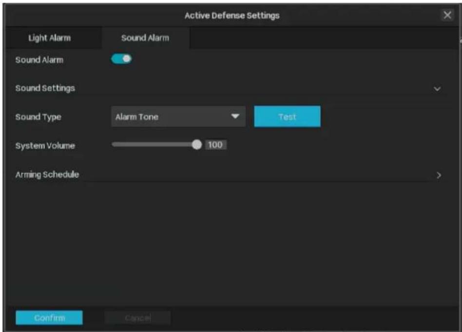
Sound Type
Specify the server address. You can enter the IP address or the domain name of the server.
System Volume Enter the server's url address.
2) Configure the arming schedule. You can click Edit to add time and quickly copy time to other days, click Confirm to save the time settings.

- Click Apply to save the settings.

Network Management
With proper network configurations, you can connect your NVR to the internet, build up mapping between internal and external ports, and manage it remotely via Cloud Services. This chapter contains the following sections:
- Configure Network Connection
- Configure Operating Mode (Only for certain models)
- Configure IPv6
- Configure Network Isolation
- Configure Network Service
- Configure DDNS
- Configure UPnP
- Configure IP Restriction
- Configure Platform Access
- Configure Email
- Configure Openapi
- Configure FTP
- Configure LLDP
- Configure SNMP

7.1 Configure Network Connection
7.1.1 Configure Basic Settings.
In Connection, you can view the connection status and configure the NVR to obtain a dynamic or static IP address.
Follow the steps below to configure the basic settings.
- Right-click on the Live View screen and click Settings in the Main Menu. Go to Network > Connection.
- Select a mode and follow the instructions below.
- To assign a static IP address to the NVR, select Static IP as the mode and configure the following parameters.

IP Address: Specify an IP address for the NVR. The IP address should be in the same segment as the gateway; otherwise, the NVR cannot connect to the internet.
Mask: Enter the subnet mask.
Gateway: Enter the IP address of the gateway device to which data packets will be sent. This IP address should be in the same segment as the NVR's IP address.
Preferred/Alternate DNS: Enter the IP address of the DNS server.
- To configure the NVR to obtain a dynamic IP address, select Dynamic IP as the mode. Note:
- A DHCP server (usually a router) is needed for the NVR to obtain a dynamic IP address.
Chapter 7 Network Management
- If the topology or subnet is changed, you should assign a new IP address to the NVR to keep the network connection. In Static IP mode, configure the basic settings manually, while in Dynamic IP mode, click Save. Then follow step 3 below to change the IP addresses of cameras.
- (Optional) If the network segment of the NVR is changed, click One-Click Networking, and then select the channels to change the IP addresses of cameras in batches. Click Confirm.
Note: The cameras should be in the same segment as the NVR, so that the NVR can discover and manage them.
4. Click Apply.
If you want to reset to factory settings, click Restore.
7.1.2 Configure Advanced Settings
In Advanced Settings, you can specify MTU (Maximum Transmission Unit) to decide the largest size of data unit that can be transmitted in the network. A larger unit can improve efficiency with more data in each packet, but it may increase network delay because it takes more time to transmit. Therefore, if you have no special needs, it is recommended to keep the default value.
To configure MTU, right-click on the Live View screen and click Settings in the Main Menu. Go to Network > Connection. Specify MTU and click Apply.
7.2 Configure Operating Mode (Only for certain models)
Some NVRs (like NVR4032H/4064H) support three operating modes: Fault-tolerant mode, Multiple-access mode, and Port Aggregation mode. You can configure the network settings according to your needs.
7.2.1 Configure Fault-tolerant Mode.
In Fault-tolerant mode, the LAN1 port and LAN2 port share the same IP address. After setting a main port, when the main port connection fails, the system enables the other port as backup port to ensure that the system's network works properly.
Follow the steps below to configure the Fault-tolerant mode.
- Right-click on the Live View screen and click Settings in the Main Menu. Go to Network > Connection.
- Select the Fault-tolerant operating mode and follow the instructions below.
- To assign a static IP address to NVR, select Static IP as the mode and configure the following parameters.

IP Address: Specify an IP address for the NVR. The IP address should be in the same segment as the gateway; otherwise, the NVR cannot connect to the internet.
Mask: Enter the subnet mask.
Gateway: Enter the IP address of the gateway device to which the data packets will be sent. This IP address should be in the same segment as the NVR's IP address.
Preferred/Alternate DNS: Enter the IP address of the DNS server.
| MTU Specify MTU (Maximum Transmission Unit) to decide the largest size of data unit that can be transmitted in the network. A larger unit can improve the efficiency with more data in each packets, but it may increase the network delay because it needs more time to transmit. Therefore, if you have no special needs, it is recommended to keep the default value. | |
| Main Network Adapter | Specify LAN1 or LAN2 as the primary network port for data transmission, and the other port will be the backup port. |
- To configure the NVR to obtain a dynamic IP address, select Dynamic IP as the mode.
Note:
- A DHCP server (usually a router) is needed for the NVR to obtain a dynamic IP address.
- If the topology or subnet is changed, you should assign a new IP address to the NVR to keep the network connection. In Static IP mode, configure the basic settings manually, while in Dynamic IP mode, click Save. Then follow step 3 below to change the IP addresses of cameras.
- (Optional) If the network segment of NVR is changed, click One-Click Networking, and then select the channels to change the IP addresses of cameras in batches. Click Confirm.

Note: The cameras should be in the same segment with the NVR, so that the NVR can discover and manage them.
- Click Apply.
If you want to reset to factory settings, click Restore.
7.2.2 Configure Multi-access Mode.
In Multi-access mode, the network settings of LAN1 port and LAN2 port are independent of each other, and the two ports work with each other. Set LAN1 and LAN2 respectively, and you can select a port as
the default route. When the system is actively connected to an external network, data is forwarded by the default route.
Follow the steps below to configure the Multi-access mode.
- Right-click on the Live View screen and click Settings in the Main Menu. Go to Network > Connection.
- Select the Multi-access operating mode and follow the instructions below.
- To assign a static IP address to NVR, select Static IP as the mode and configure the following parameters.

IP Address: Specify an IP address for the NVR. The IP address should be in the same segment as the gateway; otherwise, the NVR cannot connect to the internet.
Mask: Enter the subnet mask.
Gateway: Enter the IP address of the gateway device to which the data packets will be sent. This IP address should be in the same segment as the NVR's IP address.
Preferred/Alternate DNS: Enter the IP address of the DNS server.
MTU: Specify MTU (Maximum Transmission Unit) to decide the largest size of data unit that can be transmitted in the network. A larger unit can improve the efficiency with more data in each packet, but it may increase the network delay because it needs more time to transmit. Therefore, if you have no special needs, it is recommended to keep the default value.
Default Route: Specify LAN1 or LAN2 as the default route for data transmission.
To configure the NVR to obtain a dynamic IP address, select Dynamic IP as the mode.
Note:
- A DHCP server (usually a router) is needed for the NVR to obtain a dynamic IP address.
- If the topology or subnet is changed, you should assign a new IP address to the NVR to keep the network connection. In Static IP mode, configure the basic settings manually, while in Dynamic IP mode, click Save. Then follow step 3 below to change the IP addresses of cameras.
7.2.3 Configure Port Aggregation Mode.
In Port Aggregation mode, the two LAN ports use the same IP address to aggregate the two network ports of the NVR to form a logical physical port, which can increase the bandwidth; at the same time, the two network ports dynamically back up the settings of each other to improve the connection reliability.
Note: When Port Aggregation mode is configured, the two network ports connected to the switch must first set up port aggregation to enhance bandwidth, otherwise the network port can only dynamically back up settings.
Follow the steps below to configure the Port Aggregation mode.
- Right-click on the Live View screen and click Settings in the Main Menu. Go to Network > Connection.
- Select the Multi-access operating mode and follow the instructions below.
- To assign a static IP address to the NVR, select Static IP as the mode and configure the following parameters.

IP Address: Specify an IP address for the NVR. The IP address should be in the same segment as the gateway; otherwise, the NVR cannot connect to the internet.
Mask: Enter the subnet mask.
Gateway: Enter the IP address of the gateway device to which data packets will be sent. This IP address should be in the same segment as the NVR's IP address.
Preferred/Alternate DNS: Enter the IP address of the DNS server.
MTU: Specify MTU (Maximum Transmission Unit) to decide the largest size of data unit that can be transmitted in the network. A larger unit can improve efficiency with more data in each packet, but it may increase network delay because it needs more time to transmit. Therefore, if you have no special needs, it is recommended to keep the default value.
- To configure the NVR to obtain a dynamic IP address, select Dynamic IP as the mode.
Note:
- A DHCP server (usually a router) is needed for the NVR to obtain a dynamic IP address.
- If the topology or subnet is changed, you should assign a new IP address to the NVR to keep the network connection. In Static IP mode, configure the basic settings manually, while in Dynamic IP mode, click Save. Then follow step 3 below to change the IP addresses of cameras.
7.3 Configure IPv6
Configure the IPv6 function, and the clients can access the NVR's web management page, preview, playback and use RTSP via IPv6.
To configure IPv6, right-click on the Live View screen and click Settings in the Main Menu. Go to Network > IPv6. Toggle on to enable IPv6, configure the following parameters and click Apply.

| Mode | It includes Manual IP, DHCPv6 (Dynamic Host Configuration Protocol version 6) and SLAAC (Stateless Address Auto-configuration). |
| IP Address | In Manual IP mode, it is the NVR's IPv6 address. Its factory default value is :: If you choose DHCPv6 or SLAAC, the IPv6 address is Obtained by the NVR through DHCPv6/SLAAC. |
| Prefix Length | In Manual IP mode, the prefix-length is the subnet mask in IPv6 of the NVR, it is expressed as an integer between 1 through 128. The factory default value is 64. If you choose DHCPv6 or SLAAC, the prefix-length obtained by the NVR through DHCPv6/SLAAC. |
| Gateway | In Manual IP mode, the factory default IPv6 gateway of NVR is :: If you choose DHCPv6 or SLAAC, the IPv6 gateway is obtained by the NVR through DHCPv6/SLAAC. |
| Preferred/Alternate DNS | In Manual Mode, set the IPv6 DNS address of the NVR. The factory default IPv6 DNS address of NVR is :: If you choose DHCPv6 or SLAAC, the IPv6 DNS address is obtained by the NVR through DHCPv6/SLAAC. |
Use Static DNS: Enable to set the IPv6 DNS address of the NVR.
7.4 Configure Network Isolation
You can enable Network Isolation to isolate the NVR's connected PoE cameras from other devices, so that other devices in the LAN cannot communicate with its connected PoE cameras.
To configure Network Isolation, right-click on the Live View screen and click Settings in the Main Menu. Go to Network > Network Isolation, toggle on to enable Network Isolation, specify the following parameters and click Apply.
Internal IP: Enter the IP address of the PoE port. It is 192.168.253.1 by default.
Start IP
Specify the start IP address that the NVR assigns to cameras connected to the PoE ports. It is 192.168.253.2 by default.
POE Access to Internet
When enabled, devices connected to the PoE ports can access the internet.
7.5 Configure Network Service
You can configure the HTTPS port and service port of the NVR that can be used to access the NVR through the network. When managing and monitoring the devices via other clients, the ports configured here are used for communications of corresponding protocols.
To configure Network Service, right-click on the Live View screen and click Settings in the Main Menu. Go to Network > Network Service, specify the following parameters as needed and click Apply.

HTTPS Port: Specify a port for HTTPS protocol.
Video Service: Specify a port for protocols of video services.
Management Port: Specify a port to access the camera's live streaming web interface.
| Authentication Algorithm | Select the authentication algorithm type from the drop-down list. |
| Specify a port for RTSP (Real Time Streaming Protocol) protocol. | |
| RTSP Port | RTSP is an application layer protocol for connecting, transferring, and streaming media data in real time from IP cameras connected to the network.Specify a port for the RTSPS (RTSP over SSL) server. |
| RTSPS Port | RTSPS adds TLS encryption based on the RTSP protocol to ensure the security of data during network transmission and prevent it from being eavesdropped or tampered with. |
| Remote Stream Port Default port is 6005. This can be skipped. | |
| Authentication Algorithm | Select the authentication algorithm type from the drop-down list. |
| SRTP | When enabled, RTSP video data will be encrypted and you may be unable to play the video using third-party clients or NVRs. |
7.6 Configure DDNS
When you connect the NVR to a network, it will be assigned a dynamic IP address, and you can use this IP address to access the NVR. However, the IP address can change from time to time, and you don't know when it changes. In this case, you might apply the DDNS (Dynamic Domain Name Server) feature on the NVR to allow you to access your NVR using a domain name without checking and remembering the IP address.
Follow the steps below to configure DDNS.
- Right-click on the Live View screen and click Settings in the Main Menu. Go to Network > DDNS.
- Enable DDNS and specify the service provider: NO-IP, DynDNS, or TP-Link DDNS. Enter the username, password, and domain name of your account.

- Click Apply.
7.7 Configure UPnP
UPnP is used to establish the mapping between the internal port and external port.
Note: The NVR and cameras should be connected to the internet, and UPnP should be enabled on the gateway.
Follow the steps below to configure UPnP.
- Right-click on the Live View screen and click Settings in the Main Menu. Go to Network > UPnP.
- Enable UPnP and specify a mapping type. If you select Auto as the mapping type, the mappings are established automatically. If you select Manual as the mapping type, click ☑ to specify the external port.

Port Type: Displays the protocol type.
Internal IP: Displays the IP address of the NVR that needs to be converted.
Internal Port: Displays the port of the NVR to be converted.
External Port: Displays the external port opened by the gateway.
External IP Displays the IP address of the NVR that needs to be converted.
Status Displays the status of mapping.
- Click Apply.
7.8 Configure IP Restriction
You can set the access permissions of NVR to allow or deny the access to the NVR.
Follow the steps below to configure IP Restriction.
- Right-click on the Live View screen and click Settings in the Main Menu. Go to Network > IP Restriction
- Enable IP Restriction.

Deny List IP addresses in the list are prohibited from accessing the NVR.
Allow List Only IP addresses in the list are allowed to access the NVR.
- Click Add to add a rule.
- Click Apply.
7.9 Configure Platform Access
Configure the NVR to connect to the TP-Link video surveillance management platform, featuring real-time preview, recording playback, alarm service and device management.
Follow the steps below to configure Platform Access.
- Right-click on the Live View screen and click Settings in the Main Menu. Go to Network > Platform Access.
- Enable Access to VIGI VMS. After this feature is enabled, the connection to TP-Link Cloud will be disconnected.
| Access to VMS | Toggle on to enable the NVR's access to the local VMS, and the connection to Cloud will be disconnected. |
| IP Address/Domain Name | Enter the IP address/Domain Name of the local VMS server. |
| Port | Enter the port number of the device that the VMS server uses to access the server. Refer to the port number provided by the platform. |
- If you want to connect the NVR to the cloud, select VIGI Cloud, toggle on to open cloud service and bind the device to your TP-Link ID.
- Click Apply.
7.10 Configure Email
Configure the email settings, then the system will send an alarm email to the designated recipient when an alert is triggered.
Follow the steps below to configure Email.
- Right-click on the Live View screen and click Settings in the Main Menu. Go to Network > Email.

Authentication Whether to enable authentication.
Username The username of the sending email account.
Password The password of the sending email account. This password is generally an authorization code. You email needs to enable the IMAP service to obtain the authorization code.
Sender: The name of the sender.
Sender Email: The email of the sender.
Recipient: The name of the recipient.
Recipient Email: The email of the recipient.
SMTP Server: Enter the SMTP server address. The format is smtp.x.com, where x represents the email name, such as smtp.gmail.com.
SMTP Port: Enter the port number of the SMTP server used for email alarms.
SSL/TLS: Whether to use SSL/TLS protocol for encryption when sending email alarms.
| Attached Image | Whether to attached the image with email. The notification email has a certain number of attached alarm pictures about the event with configurable image capturing interval. |
| Interval Specify the interval to send emails. | |
2. Click Apply.
7.11 Configure ONVIF
ONVIF, or Open Network Video Interface Forum, aims to provide a standard for the interface between different IP-based physical security devices. ONVIF specifications provide a consistent way for devices from multiple manufacturers to work together. Go to Network > ONVIF, toggle on to enable ONVIF.
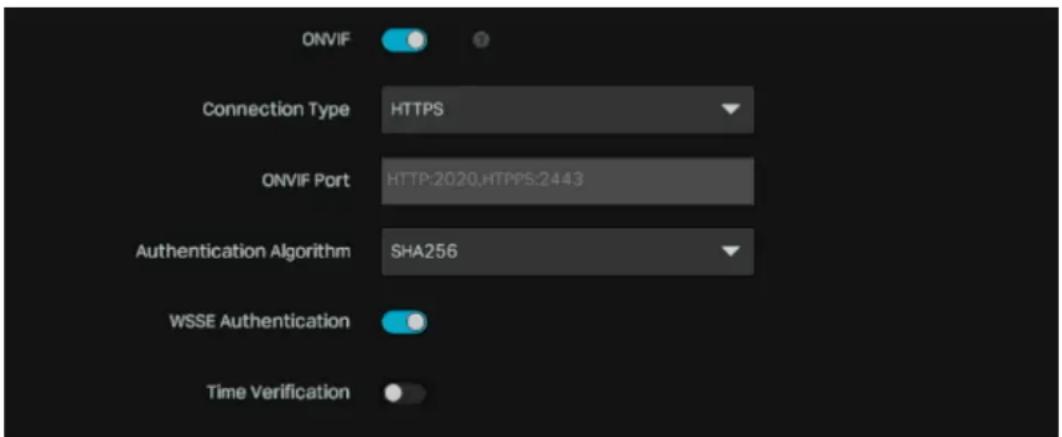
| Connection Type | Select the connection type (HTTPS, HTTP or both) that the ONVIF will use for connection. |
| ONVIF Port Specify a port for the ONVIF protocol. | |
| Authentication Algorithm | Select the authentication algorithm type from the drop-down list.. |
| WSSE Authentication | Whether to enable WSSE (Web Service Security, WEB security) authentication method. It iss a set of technical specifications for ensuring the security of Web services (such as SOAP services). Its core function is to provide identity authentication, data integrity, and confidentiality protection for Web service messages. It is one of the key technical frameworks for implementing the WS-Security (Web Service Security) standard. |
| Time Verification | Toggle on to enable the time verification method. It is a supplementary security measure proposed for WSSE (Web Service Security, WEB security) authentication method. The timeout threshold is 60s by default and cannot be changed. |
7.12 Configure Openapi
You can allow the Openapi connection to the NVR. Right-click on the Live View screen and click Settings in the Main Menu. Go to Network > Openapi, toggle on to enable Openapi and enter the Openapi port.

7.13 Configure FTP
You can configure the FTP server to save images which are captured by events.
- Right-click on the Live View screen and click Settings in the Main Menu. Go to Network > FTP.
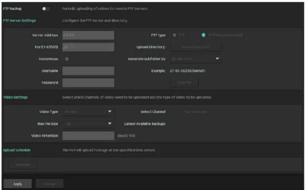
- FTP and SFTP are selectable. SFTP is recommended, and by default, file uploads are encrypted using the SFTP protocol.
- Enter the server address and port. They represent the FTP server address and the corresponding port.
- Set the username and password, and confirm the password. The FTP user should have permission to upload pictures.
- If the FTP server supports picture uploads by anonymous users, you can check Anonymous to hide your device information during upload. Note that anonymous login is not supported when the SFTP protocol is selected.
- Select the saving path for uploaded images from the Upload Path dropdown box and edit the name.
- Click Test FTP to verify the FTP server.
- Configure the video types that will be saved to the FTP server. Specify the maximum file size, the video retention period, and select the desired channel.
- Configure the upload schedule, and the videos will be uploaded to the FTP server regularly.

7.14 Configure LLDP
Enable LLDP to allow the NVR to advertise its own basic information and receive information from neighboring devices. Right-click on the Live View screen and click Settings in the Main Menu. Go to Network > LLDP, and toggle it on to enable LLDP.

7.15 Configure SNMP
You can set the SNMP, or Simple Network Management Protocol, to get device information in network management.
- Right-click on the Live View screen and click Settings in the Main Menu. Go to Network > SNMP.

- Select your SNMP version according to your actual needs.
- When enabling SNMPv1/SNMPv2c, enter the SNMP community name. Note that the access is Read only, meaning that the network management system can only view but not modify parameters of the specified view. Configure the following parameters.
| Trap Address IP Address of SNMP host. | |
| Trap Port | Port of SNMP host. The value is by default 162 and can range from 1 to 65535. |
| SNMP Port | An SNMP communication endpoint that identifies SNMP data transfers. By default the SNMP port is 161. |
- When enabling SNMPv3, enter the Read User name. Note that the access is Read only, meaning that the network management system can only view but not modify parameters of the specified view. Configure the following parameters.
| Security Levels | no auth, no priv: No authentication or privacy is used. This offers the least security and is generally not recommended for production environments.auth, priv: Both authentication and privacy (encryption) are enabled. This offers the highest level of security, protecting both the sender's identity and the data being transmitted.auth, no priv: Authentication is enabled, but no encryption is used. This provides basic security by verifying the identity of the sender. |
| Authentication Algorithm | SNMPv3 supports various authentication algorithms, including:MD5: Message Digest 5 (a widely used hash function).SHA: Secure Hash Algorithm (another hash function).SHA-256: A more secure version of SHA. |
| Authentication Password | A password used to verify the authenticity of the message sender. It should be strong and long (at least 8 characters). |
| Encryption Protocols: SNMPv3 supports encryption algorithms like: DES: Data Encryption Standard. | |
| Private Key Algorithm | AES: Advanced Encryption Standard. AES192: Advanced Encryption Standard with 192-bit key. AES256: Advanced Encryption Standard with 256-bit key. |
| Private Key Password A password used to encrypt and decrypt the message payload. | |

NVR Management
This chapter contains the following sections to introduce how to manage NVR:
- Upgrade the NVR Firmware
- Reset the NVR
- Configure Reboot Schedule for NVR
- Diagnose the NVR
8.1 Upgrade the NVR Firmware
The NVR supports Online Upgrade and Local Upgrade. Follow the steps below to upgrade the firmware.
- Get ready to upgrade the firmware.
- (For Online Upgrade) Connect the NVR to the internet first.
- (For Local Upgrade) Download the NVR firmware from TP-Link Download Center, place the firmware in an external storage device and plug the external storage device into the NVR.
- Right-click on the Live View screen and click Settings in the Main Menu. Go to System > Firmware Upgrade.
- Click the buttons to upgrade the NVR online or locally.

- (For Online Upgrade) Click Check for Update and the NVR will detect new firmware online and upgrade automatically.
- (For Local Upgrade) Click Select upgrade firmware to select the firmware from the external storage device and click Upgrade.
Note: When upgrading, please do not turn off the power of the NVR.
8.2 Reset the NVR
To reset the NVR to the factory settings, right-click on the Live View screen and click Settings in the Main Menu. Go to System > System Configuration > Settings Management. Then, click Reset.
Note: Do not perform any operations until the reset is complete. This may take several minutes.
![graph TD A["Reset"] --> B["Restore all configurations to factory default settings."] B --> C["Import Configuration File"] C --> D["Import the Configuration File to the NVR."] D --> E["Export Configuration File"] E --> F["Current NVR profile"] F --> G["VIGI NVR2016H-16MP(UN) 2.0_Current Time_config.b…](/content/2026/06/1367895/images/ff8c7018d9bb2b0afbb8a04c7a6bf03111e604289a6ea37c9acba76e38232649.jpg)
8.3 Configure Reboot Schedule for NVR
When Reboot Schedule is enabled, the NVR reboots automatically and regularly at the specified time.
Follow the steps below to configure Reboot Schedule for the NVR.
- Right-click on the Live View screen and click Settings in the pop-up Main Menu. Go to System > System Configuration > Reboot Schedule.
- Enable Reboot Schedule, and specify the week day and reboot time. Click Apply.

8.4 Diagnose the NVR
The NVR supports two diagnostic tools, Rapid Diagnosis and Custom Diagnosis. You can diagnose the NVR to test the network connection and delay.
Follow the steps below to diagnose the NVR.
- Right-click on the Live View screen and click Settings in the Main Menu. Go to System > System Configuration > Diagnostic Tools.
- Use a diagnostic tool and view the results.
- To quickly diagnose the network connection, click Rapid Diagnosis.

| Gateway/Extranet/Cloud Service Connection | Displays the connection status between the NVR and gateway/extranet/TP-Link Cloud. |
| Delay | Displays the delay in milliseconds of each channel. Not Connected means that the NVR cannot communicate with the camera. |
Packet Loss Rate: Display the ratio of lost packets.
• For Custom Diagnosis, select an operation and specify the parameters. Click Start Diagnosis.
Operation: Select an operation.
Ping: The NVR sends several packets to the specified IP address or domain to test the connection between them.
Tracert: The NVR tries to trace the route to the specified IP address or domain within limited hops and record the route.
IP/Domain Name: Specify an IP address or a domain name to diagnose the connection.
| Packet Number (For Ping diagnose) Specify how many packets the NVR sends to the specified IP/domain name. | |
| Packet Size (For Ping diagnose) Specify the size of packets. | |
| Timeout (For Ping diagnose) Specify the maximum time that the NVR waits for response of a ping packet. If no response is received after the time, the ping packet will be regarded as lost. | |
| Hop Count (For Tracert diagnose) Specify the maximum hops when tracing the route. | |
| Diagnostic Results | If you select Ping as the operation, the results show the statistics of ping packets.If you select Tracert as the operation, the results show the route that the NVR traces to the specified IP address or domain name. |

System Management
This chapter guides you to configure the basic and advanced settings of your NVR, export and import settings, and view system logs and messages on the NVR. VIGI NVR allows users to create and modify administrator accounts based on their needs. This chapter includes the following sections:
- Configure Basic Settings
- Modify System Time
- Configure Interface Output
- Configure Channel-Zero
- Manage User Accounts
- Import and Export Settings • View System Logs • View System Information
9.1 Configure Basic Settings
To configure the settings for your NVR, right-click on the Live View screen and click Settings in the pop-up main menu, then go to System > Basic Settings > Basic Settings.

Device (NVR) Name: Displays the name of the NVR.
Language: Set the system language.
| Power Line Frequency | Set the Power line frequency consistent with local utility settings to eliminate image flickering associated with fluorescent lights. |
| Menu Timeout | Set the time to control how long the login can be inactive on the NVR. By default, users already logging into the NVR are automatically logged out after 10 minutes. |
| Switching Interval | Set the interval for displaying the live view screen when switching is enabled. Click the Main Menu to start switching. The range is from 5s to 120s. |
| Alarm Full Screen Display Time | Set the dwell time of channels in full screen when events are detected. |
| Setup Wizard Click the check box to run setup wizard when the NVR reboots. | |
| Mouse Sensitivity | Determines the speed of a mouse pointer and how fast it moves on the screen. |
9.2 Modify System Time
VIGI NVR provides two methods to modify the system time. You can also select the time zone according to your region. To configure these settings, right-click on the Live View screen and click Settings in the pop-up main menu, then go to System > Basic Settings > Date.
NTP
NTP (Network Time Protocol) can automatically get the system time from the Internet. It is recommended to keep the default server address.

Manually
You can set the system time manually.

9.3 Configure Interface Output
In Interface Output, you can select the display resolution for your monitor and choose to display the channel number on the Live View screen and the images in the original scale. To configure these settings, Right-click on the Live View screen and click Settings in the pop-up main menu, then go to System > Basic Settings > Interface Output.

| Main Screen Display Preference | Set the output interface for Main Screen when the device is connected to two monitors, HDMI or VGA.If Both is selected, both HDMI and VGA will be used as the output interface for Main Screen. |
| Resolution | Select the screen resolution according to your needs. WithAdaptiveselected, the NVR automatically selects the highest resolution supported by the screen. |
| Display Channel Number | Display the channel number on the Live View Screen. |
| Display Original Scale Screen | Display the images on the Live View screen in the original scale. |
9.4 Configure Channel-Zero
With Channel-Zero enabled, you can view all cameras connected to the NVR in one live view screen, but only consume the bandwidth of one channel. This function helps ensure smooth video for remote
users. To configure these settings, Right-click on the Live View screen and click Settings in the pop-up main menu, then go to System > Basic Settings > Channel-Zero and toggle on to enable it.

Video Frame Rate
Specify the frame rate of the videos. The video is smoother when the rate increases.
Maximum Bit Rate Specify maximum number of bits that are conveyed or processed per unit of time.
Resolution Specify the resolution of video stream. The screen displays images clearer when the resolution increases.
Output Screen The Channel-Zero displays the same image as the selected output interface.

9.5 Manage User Accounts
You can modify the default user account (admin) and create user accounts based on your needs. The administrator has the permission to add and delete other user accounts. The Administrator user name is admin and the password is set when you set up your NVR for the first time. To configure these settings, right-click on the Live View screen and click Settings in the pop-up main menu, then go to System > User Management.
■ Modify Administrator Account
For the administrator account, you have all the permissions to manage the NVR. Administrator user name is admin and the password is set when you set up your NVR for the first time. Click to modify the settings.

You can change the gesture password, the login password of the NVR, the preset password for cameras, and the email address for resetting the NVR and cameras.

■ Add an Account
You can create user accounts with different permissions to manage the NVR. Follow the steps below to add a new user account.
- Click Add. Enter the username and set the user level to Operator or User. The operator shares the same permissions as the administrator account. The user only watches the live view and playback, adds cameras in Live View screen, and checks the logs of your NVR.

- Set the password for logging in to the account.
- Click Save.
♥ 9.6 Import and Export Settings
Follow the steps below to import and export the configuration file of your NVR.
Note: Before your operation, prepare an external storage device and plug it into the USB slot on the front panel of your NVR.
- Right-click on the Live View screen and click Settings in the pop-up main menu, then go to System > System Configuration > Settings Management.
![graph TD A["Reset"] --> B["Restore all configurations to factory default settings."] B --> C["Import Configuration File"] C --> D["Import the Configuration File to the NVR."] D --> E["Export Configuration File"] E --> F["Current NVR profile"] F --> G["VIGI NVR2016H-16MP(UN) 2.0_Current Time_config.b…](/content/2026/06/1367895/images/0cfbad931f13882e0d8b95e03ab27f3939e214c7e8e640ac7ed1e3ae19abfbc1.jpg)
- Click Import Configuration File or Export Configuration File.
- For configuration file import, select the file and click Import Configuration.

- For configuration file export, select the file and click Export Configuration.

9.7 View System Logs
The NVR uses logs to record, classify, and manage the messages of the system and devices. You can search, view, and export the logs.
Note: To export logs, a USB external storage device is required.
Follow the steps below to search and export the logs.
- Right-click on the Live View screen and click Information in the pop-up Main Menu. Go to System Logs > System Logs.
- Specify the time range and log types and click Search. The filtered logs appear in the table. To view detailed information, click View Details.

Start/End Time: Specify a time range to filter the logs based on the recording time.
Type: Select a main type from the drop-down list to filter the logs. You can also click Select Subtypes to specify subtypes.
All: All types of logs.
Alarm: Alarms triggered by events, such as tampering, line crossing, and area intrusion.
Exception: Abnormal events that may influence NVR's functions, such as video signal lost and errors of hard drive.
Operation: Operations that take place on the NVR, such as login and upgrade.
Information: Informational messages, such as local drive information and RTSP progress.
- Click Export Log and select a file path in the pop-up window. Click Export Log. Note that an external storage device is required to use this feature.
9.8 View System Information
Right-click on the screen and click Information in the pop-up main menu, then go to System Information.
Basic Information
Click Basic Information to view the device information, internet information, and storage information.

Channel Information
Click Channel Information to view the channel number, channel name, network connection status, the IP address of the camera, and the status of motion detection.
| No. | Channel Name | Connection Status | Channel IP | Motion Detection |
| 1 | VIGI C485 1.0_653C | - Connected | 192.168.0.3 | Enabled |
| 2 | VIGI C540 2.0 | - Connected | 192.168.0.2 | Enabled |
Stream Information
Click Stream Information to view the recording parameters of a certain camera.
| No. | Recording Status | Stream Type | Video frame rate | Resolution | Bit Rate |
| 1 | Enable | Main Stream | 25fps | 3840 x 2160(4x) | 4096kbps |
| 2 | Enable | Main Stream | 25fps | 2560 x 1440(2K) | 3504kbps |
No. Displays the channel number.
| Recording Status The channel starts or stops recording. | |
| Stream Type | Main Stream: Refer to the high definition quality for your live view and the larger size of recording files.Substream: Refer to the standard definition quality for your live view and the smaller size of recording files. |
| Video Frame Rate | Specify the frame rate of the videos. The video is smoother when the rate increases. |
| Resolution Specify the resolution of video stream. The screen displays images clearer when the resolution increases. | |
| Bit Rate | Specify the number of bits that are conveyed or processed per unit of time. |
Hard Drive Information

Disk No. Displays the number of the hard drive.
Disk Capacity Displays the total space of the hard drive.
Free Space Displays the remaining storage capacity of the hard drive.
Status: Displays the status of the hard drive.
Type: Read and write: The data on the hard drive can be read and written. Read-only: The data on the hard drive can only be read.
■ Internet Information
You can view the internet information of your NVR and the current network resource statistics.
| Internet Information |
| IP |
| 192.168.0.135 |
| IPv6 |
| : |
| MAC Address |
| 00:FF:00:40:E0:A5 |
| Connection Status |
| Normal |
| MTU |
| 1500 |
| Port Mode |
| 1000M Full Duplex |
| Network Resource Statistics |
| IP Channel Access Bandwidth |
| 9.00Mbps |
| Bandwidth of Net Receive Idle |
| 151.00Mbps |
IP: Displays the IP address of your NVR.
MAC Address: Displays the MAC Address of your NVR.
Connection Status: Displays the network connection status of your NVR.
MTU: Refers to the maximum transmission unit, which is the largest data packet a network-connected device will accept.
Port Mode: Displays the modes of transmission and the data speed of ports.
For example, 100M Full Duplex means the Ethernet port of the NVR can send and receive one million bits per second in both directions.
IP Channel Access Bandwidth: Displays the bandwidth used by IP cameras.
Bandwidth of Net Receive Idle: Displays the remaining received bandwidth.
You can view the event type, occurred time, and the channel which detects events.
| Event Name | CH | Event Time |
| Motion Detection | 2 | 2024-12-18 06:53:12 |
| Motion Detection-Human | 1 | 2024-12-18 06:46:35 |
| Hard drive 1 password error | - | 2024-12-17 09:18:17 |
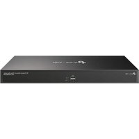
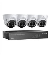


- ABOUT THIS GUIDE
- GET STARTED
- CONFIGURE YOUR NETWORK CAMERA
- LIVE VIEW
- CONFIGURE THE SCREEN LAYOUT
- CONFIGURE LIVE VIEW SETTINGS VIA TOOLBAR
- CHANGE PICTURE MODE
- RECORDING AND STORAGE
- CONFIGURE RECORDING SCHEDULES
- RECORDING CONTROLS
- MANAGE HARD DRIVE
- EXPANSION STORAGE (ONLY FOR SOME MODELS)
- PLAYBACK
- EVENTS AND ALERTS
- NETWORK MANAGEMENT
- CONFIGURE PORT AGGREGATION MODE
- NVR MANAGEMENT
- SYSTEM MANAGEMENT
- CONVENTIONS
- MORE INFORMATION
- CONNECT THE HARDWARE
- SET UP NVR
- CONFIRM THE BASIC INFORMATION
- CONFIGURE THE ACCOUNT SETTINGS
- ADD CAMERAS TO THE NVR
- ADD CAMERAS SINGLY OR IN BATCHES
- ADD UNINITIALIZED CAMERAS
- WHEN PLUG AND PLAY ENABLED
- ADD INITIALIZED CAMERAS
- WHEN PLUG AND PLAY DISABLED
- ADD A CAMERA TO A CERTAIN SCREEN
- CLICK
- ADD CAMERAS MANUALLY
- CLICK ADD MANUALLY
- ENTER THE INFORMATION OF THE CAMERA TO ADD IT. FOR VIGI SECURITY CAMERA, ENTER THE IP ADDRESS AND PASSWORD. CLICK ADD
- IP ADDRESS THE IP ADDRESS OF THE CAMERA
- CONTROL PROTOCOL
- MODIFY IP ADDRESSES OF CAMERAS
- PLUG AND PLAY SETTINGS
- ADD WITHOUT LOGIN
- DEVICE ACCESS ALERT
- DEVICES LIMITED TO ACCESS
- CONFIGURE IMAGE EFFECTS
- CONFIGURE IMAGE SETTINGS
- SELECT A CHANNEL AND CONFIGURE THE FOLLOWING PARAMETERS
- ILLUMINATOR SETTINGS
- CONFIGURE OSD SETTINGS
- CONFIGURE PRIVACY MASK
- CONFIGURE SPLICING (ONLY FOR CERTAIN MODELS)
- CONFIGURE STREAM SETTINGS
- CONFIGURE MAIN STREAM AND SUBSTREAM
- CONFIGURE AUDIO
- SELECT A CHANNEL AND CONFIGURE THE SETTINGS AS NEEDED
- CONFIGURE ROI
- CONFIGURE SRTP
- CONFIGURE PAN&TILT (ONLY FOR PT CAMERAS)
- PRESET AND CALL POSITIONS
- PRESET AND CALL PATHS IN PATROL SCAN
- PRESET AND CALL PATTERNS IN PATTERN SCAN
- ENABLE PARK
- TARGET TRACK
- PREVIEW PRESET SETTINGS
- CONFIGURE POE CHANNEL (ONLY FOR POE NVRS)
- MANAGE YOUR CAMERAS
- MODIFY CAMERA CONNECTION PARAMETERS
- CLICK THE TABLE AND MODIFY THE NAME. CLICK SAVE
- CHANGE THE PASSWORD AND RESET EMAIL
- NOTE
- UPGRADE THE FIRMWARE
- CONFIGURE SCHEDULED REBOOT
- LOAD DEFAULT
- REMOVE CAMERAS FROM THE NVR
- CHANGE THE SCREEN LAYOUT QUICKLY
- MERGE SCREENS IN SETTINGS
- REARRANGE CHANNELS IN SETTINGS
- CUSTOMIZE RECORDING SCHEDULE
- METHOD 1: VIA TIME BAR
- CONFIGURE ADVANCED RECORDING SETTINGS
- CONFIGURE STORAGE DISK GROUP
- CONFIGURE DISK QUOTA
- VIEW AND CONFIGURE SETTINGS OF HARD DRIVE
- ADD EXTERNAL HARD DRIVE TO NVR
- BAD SECTOR DETECTION
- S.M.A.R.T DETECTION
- SELECT THE DISK AND SELF-CHECKING TYPE
- CLICK START DETECTION ON THE RIGHT
- LONG-TERM STORAGE (ONLY FOR SOME MODELS)
- BACKUP RECORDINGS
- CAUTION
- SEARCH
- EXPORT RECORDINGS
- INSTANT PLAYBACK
- PLAY NORMAL RECORDINGS
- PLAY RECORDINGS WITH TAGS
- STEP 1: ADD TAGS TO RECORDING FILES
- STEP 2: SEARCH TAGS
- STEP 3: PLAY THE RECORDING FILE WITH A TAG
- PLAYBACK RECORDINGS OF EVENTS
- PLAYBACK OPERATIONS
- BASIC PLAYBACK OPERATIONS
- SET SMART PLAYBACK RULES
- EDIT RECORDINGS
- MOTION DETECTION
- CHANNEL LINKAGE
- CHANNEL ALARM OUTPUT
- CAMERA TAMPERING
- LINKAGE ACTION
- ALARM OUTPUT LINKAGE
- AO1/AO2/AO3/AO4 WHEN AN EVENT IS TRIGGERED, THE NVR WILL ALSO BE TRIGGERED
- HUMAN DETECTION
- PTZ LINKAGE WHEN AN EVENT IS TRIGGERED, THE NVR OR ITS CONNECTED CAMERAS THAT SUPPORT THIS FEATURE WILL EXECUTE PRESET OR PATROLS. PLEASE CONFIGURE THE PRESET AND PATROL ON THE CAMERAS
- CLICK APPLY TO SAVE THE SETTINGS
- VEHICLE DETECTION
- LINE CROSSING DETECTION
- INTRUSION DETECTION
- REGION ENTERING DETECTION
- REGION EXITING DETECTION
- LOITERING DETECTION
- OBJECT ABANDONED/REMOVAL DETECTION
- SCENE CHANGE DETECTION
- AO1/AO2/AO3/AO4: WHEN AN EVENT IS TRIGGERED, THE NVR WILL ALSO BE TRIGGERED
- PTZ LINKAGE: WHEN AN EVENT IS TRIGGERED, THE NVR OR ITS CONNECTED CAMERAS THAT SUPPORT THIS FEATURE WILL EXECUTE PRESET OR PATROLS. PLEASE CONFIGURE THE PRESET AND PATROL ON THE CAMERAS
- ABNORMAL SOUND DETECTION
- QUEUE DETECTION
- AO1/AO2/AO3/AO
- SMART FRAME
- VCA
- CHAPTER 6 EVENTS AND ALERTS
- GO TO EVENT > VCA > FACE ANALYSIS
- ENABLE FACE ANALYSIS AND SET THE ALARM SCHEDULE
- VIDEO SIGNAL LOSS DETECTION
- OFFLINE AND IP CONFLICT
- DISK EXCEPTION
- LOGIN EXCEPTION
- HARDWARE EXCEPTION (ONLY FOR POE MODELS)
- FTP BACKUP EXCEPTION (ONLY FOR CERTAIN MODELS)
- FAN EXCEPTION (ONLY FOR CERTAIN MODELS)
- ALARM DEVICE (ONLY FOR CERTAIN MODELS)
- ALARM OUTPUT
- DISARMING
- ALARM SERVER
- ACTIVE DEFENSE
- CONFIGURE THE SOUND ALARM
- CONFIGURE NETWORK CONNECTION
- CONFIGURE BASIC SETTINGS
- CHAPTER 7 NETWORK MANAGEMENT
- CLICK APPLY
- CONFIGURE ADVANCED SETTINGS
- CONFIGURE OPERATING MODE (ONLY FOR CERTAIN MODELS)
- CONFIGURE FAULT-TOLERANT MODE
- CONFIGURE MULTI-ACCESS MODE
- CONFIGURE IPV
- CONFIGURE NETWORK ISOLATION
- CONFIGURE NETWORK SERVICE
- CONFIGURE DDNS
- CONFIGURE UPNP
- CONFIGURE IP RESTRICTION
- CONFIGURE PLATFORM ACCESS
- CONFIGURE EMAIL
- CONFIGURE ONVIF
- CONFIGURE OPENAPI
- CONFIGURE FTP
- CONFIGURE LLDP
- CONFIGURE SNMP
- UPGRADE THE NVR FIRMWARE
- RESET THE NVR
- CONFIGURE REBOOT SCHEDULE FOR NVR
- DIAGNOSE THE NVR
- MODIFY SYSTEM TIME
- NTP
- MANUALLY
- CONFIGURE INTERFACE OUTPUT
- CONFIGURE CHANNEL-ZERO
- VIDEO FRAME RATE
- MANAGE USER ACCOUNTS
- MODIFY ADMINISTRATOR ACCOUNT
- ADD AN ACCOUNT
- ♥ 9.6 IMPORT AND EXPORT SETTINGS
- VIEW SYSTEM LOGS
- VIEW SYSTEM INFORMATION
- BASIC INFORMATION
- CHANNEL INFORMATION
- STREAM INFORMATION
- HARD DRIVE INFORMATION
- INTERNET INFORMATION
Brand : TP-LINK
Model : VIGI NVR2016H-16MP
Category : VCR