BKFDE300145 - Système d'installation électrique au sol HAGER - Free user manual and instructions
Find the device manual for free BKFDE300145 HAGER in PDF.


| Product Type | Residual Current Circuit Breaker (RCCB) |
| Dimensions (H x W x D) | 85 mm x 36 mm x 70 mm |
| Weight | 0.1 kg |
| Rated Voltage | 230 V AC |
| Rated Current | 16 A |
| Rated Frequency | 50/60 Hz |
| Number of Poles | 2 |
| Tripping Characteristics | Type A |
| Rated Residual Operating Current | 30 mA |
| Breaking Capacity | 10 kA |
| Protection Degree | IP20 |
| Operating Temperature | -25°C to +55°C |
| Mounting | DIN rail (35 mm) |
| Material | Thermoplastic |
| Energy Limiting Class | 3 |
| Functions | Overload protection, short-circuit protection, residual current protection, isolation |
| Maintenance | Clean with dry cloth; no lubrication required |
| Safety | Do not open; installation by qualified electrician only |
| Spare Parts | Not user-serviceable; contact Hager support |
| Reparability | Replaceable unit; no internal repairs possible |
| General Information | Hager brand; manufactured in Germany |
Frequently Asked Questions - BKFDE300145 HAGER
User questions about BKFDE300145 HAGER
0 question about this device. Answer the ones you know or ask your own.
Ask a new question about this device
Download the instructions for your Système d'installation électrique au sol in PDF format for free! Find your manual BKFDE300145 - HAGER and take your electronic device back in hand. On this page are published all the documents necessary for the use of your device. BKFDE300145 by HAGER.
USER MANUAL BKFDE300145 HAGER
Floor installation systems
Basic manual
natural_image
Modern office interior with white tile flooring, white desks, and large windows overlooking greenery (no visible text or symbols)Table of Contents
FAQs 4
Basic knowledge ....18
Basic planning principles ....20
Requirements for installation technology 20
Requirements from building conception 20
Requirements for organisation 20
Requirements for security 21
Installation requirements / construction requirements ....21
Duct systems 22
Screed-covered duct system 22
Screed-flush duct systems 23
On-floor duct system 24
Raised floor installation system 24
Cavity floor installation system 25
Basic principles of screed ....26
Screed structure 26
Screed work 27
Screed types 27
Floor structure 29
Floor structure 50 mm 29
Floor structure 75 mm ....30
Floor structure 105 mm ....30
Information on the floor covering and for the floor layer 31
Information on the floor covering ....31
Information for the floor layer 31
Determining the cable volume 32
Bend radii 33
Cable volume of most common installation cables 34
Power supply and device installation units 36
IP degree of protection 42
IK degree of impact resistance 43
Mechanical/thermal loads 44
Standardisation and testing 45
Erector specifications ....48
Protection against electric shock 48
Mechanical load of cables 48
Separation of different services 49
Fire protection 49
Equipotential bonding 50
Inter-unit working 51
Inter-unit working - Screed work 51
General information for screed layers ....51
Inter-unit working - Floor covering work 51
Inter-unit working - Building cleaning ....51
Sound protection and impact noise ....52
Impact noise reduction for floor installation systems ....52
Appendix 54
Overview of floor installation systems - cable assignment ....54
Reference sources of standards and specifications ....61
FAQs
7 questions - 7 answers
To meet all the requirements during the planning phase, you should get to grips with these 7 questions. This ensures that you will obtain the right duct system solution for your construction project.
The answers to your questions will provide you with the right solution for your construction project. Starting with the right duct system, the screed height, the floor coverings and their care through to the installation units.
Question 1: Which floor installation system is to be used?
☑ Screed-covered floor system
☑ Screed-flush floor system
On-the floor system
☑ Cavity floor system
☑ Raised floor system
Question 2: How is the cable volume calculated?
Cable volume calculation ( d^2 )
Data/communication technology
Multimedia technology
Energy technology
Question 3: How high is the planned floor structure?
☑ Nominal screed thickness, incl. possible insulation layers
√ Thickness of floor covering
Question 4: Which floor covering will be laid?
Parquet
Vinyl
Linoleum
☑ Tiles/granite
Carpet
Question 5: How will the floor covering be cleaned?
Dry/moist cleaned
Wet cleaned
Question 6: What are the maximum loads that can occur?
Standard
Drive-over
Heavy-duty
Question 7: Which supply and installation units are required?
Size
☑ Number of installable devices
Shape
Material
Answer 1: Which floor installation system is to be used?
A distinction is made between 5 standard floor systems. The appropriate floor system sets the course from the very start. Depending on the system, only certain products may be used. Whether this is a screed-covered duct system, which is often used in new buildings, or an on-floor duct system, which is often used during renovations. The rough direction is entirely different. Specific solutions and combination options are available for each system.
Using these aspects, it is possible to make a rough selection of the right duct system.
Screed-covered duct system

natural_image
3D architectural rendering of a modern building complex with curved walkways and structural elements (no text or symbols visible)The screed-covered duct system is suitable for all types of screed. No matter whether composite cement, floating screed, flowing screed or, with special precautions, also mastic asphalt / hot floor screed. The screed-covered duct system can be used in residential and functional buildings.
Flush-screed duct systems

natural_image
3D rendering of a corner wall with plastic components and a curved architectural element (no text or symbols visible)The screed-flush tehalit.BKB makes energy, data and communication connections available around the room. Besides its adaptability to state-of-the-art technology, it is also open to any form of interior design: It can be assigned with all kinds of dry cleaned floors. Here, the height adjustment, which is accurate to the millimetre, can offer a "smooth" end - whilst the comprehensive range of fittings adapts exactly to any angle.

natural_image
Architectural floor plan showing structural beams and a curved water channel (no text or labels)This height-variable system is used anywhere where it is not clear how the "final installation" will be and/or the highest level of flexibility is desired. Duct widths of up to 600 mm allow the duct to be used wherever high volumes of cables occur. The shiny version of the screed-flush duct is used in production halls and in office and administration buildings. Its very low height means that the duct is also suitable for very flat screed heights of 30 mm or more.
On-floor duct system

natural_image
Interior architectural rendering of a modern room with wall and floor elements (no text or symbols)industrial buildings.
This duct system is particularly suitable for renovations of old buildings and the modernisation and expansion of building installations. The main areas of use are renovations of office and administration buildings, as well as construction projects requiring the rapid erection of electrical systems on already completed floors. If it is not possible to install underfloor ducts in the screed due to building protections on static or monument protection grounds, then the on-floor ducts are routed on the floors. The robust on-floor ducts are also used in assembly facilities, laboratories or
Raised floor system

natural_image
Industrial testing setup with a perforated metal panel and connected cables (no visible text or symbols)Open plan offices or large-area call centres divided up into many computer workstations using partitions and which must remain structured cannot avoid this flexible system. This also applies to computer server rooms constructed with raised floors, which offer the greatest possible flexibility through their construction. In this way, completely networked power and data networks are integrated into showrooms or trade fair stands which are rebuilt according to requirements.
Cavity floor system
natural_image
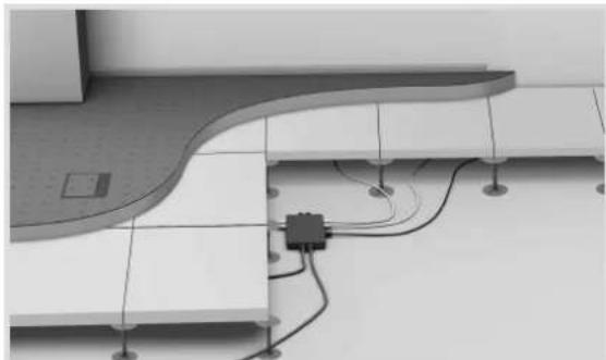
Architectural floor plan showing wall and floor structure with wiring and a small component (no text or symbols visible)In cavity floors, prefabricated lined bodies are laid out on the raw ceiling and then cast with screed. In contrast to raised floors, in which individual plates can be exchanged as required, a cavity floor is a closed screed plate on stilts. In a similar manner to the raised floor, wiring can be designed very flexibly using plug and play systems.
Answer 2: How is the cable volume calculated?
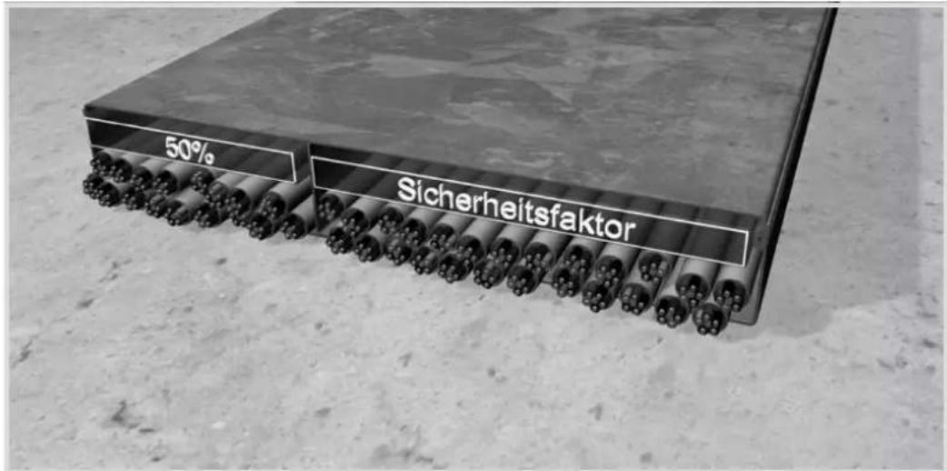
The cable volume is required to define the correct duct size. However, as, in practice, cables can never lay next to each other in a perfectly parallel and space-saving manner, the formula (d)^2 or the diameter squared is used. The ducts should only be 50% full, to leave space for possible refitting later on. This means that the cables can also be pulled through the duct more easily.
In addition, it should be noted that, in this calculation, no floor tanks or outlets which might interrupt the cable path are taken into account.
In practice, power and data cables are routed separately in the duct. Separating webs divided the duct up into multiple compartments. If this applies, then the space requirements must be calculated for each compartment individually.
With stronger current loads of the cables, cable heating should be taken into account. In addition, all the relevant regulations, such as DIN VDE 0100, must also be taken into account.
Answer 3: How high is the planned floor structure?
The height of the planned underfloor system also has a key role to play in the planning and installation of underfloor cable systems. In particular, with screed-covered floors and screed-flush floors, this information is used to include the appropriate elements for height adjustment into the planning and installation. Different products and solutions are used, depending on the height.
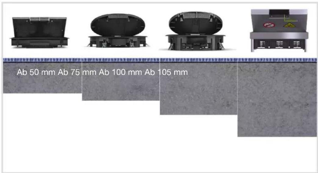
In general, the prescribed floor structure specifies the area available for the floor solution.
- Hinged cover with ultra-flat installation depth for a floor structure of 50 mm or more
- Standard supply units with floor covering recesses of 5 mm for a floor structure of 75 mm or more
- Standard supply units with floor covering recess of 12 mm for a floor structure of 100 mm or more
- Stainless steel cassettes for a floor structure of 105 mm or more
Answer 4: Which floor covering will be laid?
Often, the floor covering is specified in a construction project. It is stated whether there will be a carpeted floor, laminate, parquet, tiles, stone, PVC or a linoleum covering. Each covering has a different height. This means that not every covering fits in every installation unit. Three different heights are available here. Supply units are available for smaller covering heights up to 5 mm or up to 12 mm and stainless steel cassettes are available for heights of up to 23 mm.

natural_image
Close-up of a circular device with a 5 mm scale label on a textured surface (no other text or symbols visible)PVC coverings are often only 3 to 4 mm thick. For such coverings, and for thin carpets and linoleum, standard supply units with a 5 mm frame height are ideal.

natural_image
Blue textured surface with a small blue object labeled '32 mm' attached to its top, no other text or symbols visible.Carpeted floors and laminate generally have a thickness of 8 to 10 mm, whilst some laminate types with adhesive are thicker still. Here, standard frames of 10 mm height are insufficient. Therefore, Hager offers, as the sole provider, standard supply units with a 12 mm frame height. If the frame is too high, then cover inlays of 1 to 2 mm can be inserted to support the floor covering.
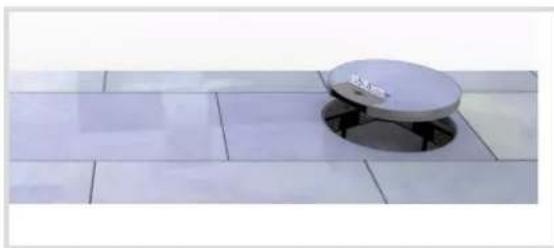
natural_image
Exterior view of a modern office building (no signage)For coverings such as parquet or stone tiles, Hager can offer stainless steel cassettes with a base recess of up to 23 mm or up to 38 mm, according to the version. Even with very thick floor coverings, this guarantees tidy work without bumps and dips.
Answer 5: How will the floor covering be cleaned?
The cleaning category is aligned to the type of floor covering. Carpeted floors are usually dry cleaned, whilst tiles are normally moist or wet cleaned.
Dry cleaned and "moist cleaned" floors
Floor coverings that can be vacuumed (e.g. carpeted floors) or those which can be wiped over with moist but not wet cleaning devices (e.g. laminate) are combined as “dry cleaned floors”. All the standard supply units, cable outlets and pedestals from Hager can be used on such floors.
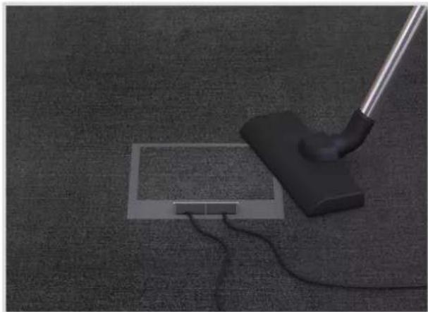
natural_image
Close-up of a vacuum cleaner placed on a carpet with wires and a small rectangular component (no visible text or symbols)Image 1: Dry cleaned floors
Wet cleaned floors
Floors subject to serious degrees of contamination - such as stone floors in factory halls - must be wet cleaned using liquid cleaning agents. For these “wet cleaned floors”, Hager can offer “water-tight” system components, such as supply units with integrated water stream protection, which is offered in either aluminium or polyamide.

natural_image
Close-up of a black cylindrical object placed on a metallic circular base on a tiled floor (no text or symbols visible)Image 2: Wet cleaned floors
Answer 6: Which loads can occur?
Different load requirements occur, depending on the circumstances. In everyday office life, loads of up to 1500 N will generally occur. However, in public buildings, such as airports or stations, this amount is usually incorrect. Daily work with luggage carts, cleaning machines or mobile scaffolding increases the load. The ability to be driven on is often also a condition in car or other showrooms. In assembly halls or warehouses, the load is frequently greatly increased by loaded forklifts or trucks.
1500 N Standard

natural_image
3D rendered image of a mechanical component pressing a square component on a textured surface (no text or symbols visible)Image 3: 1500 N Standard
All the supply units and stainless steel cassettes are designed according to the standard for a 1500 N load. These include all the supply units, all the stainless steel cassettes, screed-flush ducts, on-floor ducts, etc. This is fully sufficient for the normal loads of everyday office life.
7500 N drive-on

natural_image
Close-up of a metallic circular component with concentric rings placed on tiled floor (no text or symbols visible)Image 4: 7500 N drive-on
VANR12 supply unit
The VANR12 supply unit is designed for increased loads. The supply unit is made of aluminium and can be driven over in a car.
20000 N heavy duty
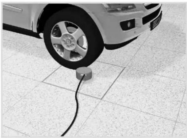
natural_image
Close-up of a car's wheel connected to a power plug on tiled floor (no visible text or symbols)Image 5: Heavy duty cassettes
The EKSQ405xx heavy duty cassette is used in car showrooms. This stainless steel cassette is supported by a solid heavy duty frame, thus offering sufficient stability for extremely high loads.
Answer 7: Which installation units are required?
Supply and installation units
To supply commercial buildings in a sensible manner, it is wise not to cut corners - with regards to both energy and also information and data. The electraplan supply and installation units. VE-EEs can cover any customer requirements.
They are compatible with almost any electraplan floor installation system and can be equipped with six to twelve connector boxes, according to requirements. The supply units are available in a range of materials, shapes and colours.
Each device casing can be equipped variably: With protective contact sockets or support bar devices for network and multimedia technology.
Polyamide supply unit

natural_image
Exterior view of a modern cylindrical mechanical or architectural component with mounting brackets (no text or symbols visible)The standard material for supply units is polyamide. Polyamide frames can withstand a load of up to 1.5 kN (DIN specification) - ideal for classic floor use. Large selection for use with 6, 9, 10 or 12 sockets, for example:


Aluminium supply unit

natural_image
Exterior view of a mechanical component with mounting holes and ventilation slots (no text or symbols visible)In conjunction with high-quality floor coverings - e.g. stone tiles - it is wise to use aluminium supply units. They are not only more stable, but also provide a more elegant floor appearance. Hager can offer aluminium units that can withstand loads of up to 7.5 kN for strong loads in public buildings - e.g. showrooms, stations or airports. Sizes: 2 sizes for use with 6 or 12 sockets, for example.

Stainless steel supply units

natural_image
Exterior view of a modern office building (no signage)Stainless steel supply units are particular robust:
They correspond to the DIN load specifications of 1.5 kN. As a heavy duty cassette, they can even withstand loads of up to 20 kN (see Page 48). A further advantage: Thanks to their thin edge, they are barely noticeable in the floor - if they are, then its due to their fine appearance.
Sizes: 2 sizes for use with 6 or 12 sockets, for example.

Basic knowledge
Important note
This document explains the relevant principles for the installation of floor installation systems and routing cables in these systems.
The contents of this document are based on the currently applicable rules and regulations as well as our own test findings. No generally applicable legal obligation shall be derived from the contents of this document.
Basic planning principles

natural_image
Overhead view of four people gathered around a white table with blueprints and a laptop, no visible text or symbols.Image 6: Planning
Requirements for installation technology
When planning and selecting the floor installation system, the following points must be observed with regard to the installation system requirements:
– Number of services (power, communication, data, multimedia)
– Filling factor of the electrical installation ducts
- Cable bend radii
- Reserve
- Concurrence factors
- Intended for indoor areas
Requirements from building conception
The following preconditions are to be taken into account on account of the use profiles of the individual rooms or the overall building:
- Type of room (dry or wet)
– Floor covering version (dry or wet cleaned)
– Thickness of the floor covering - Type and version of the screed
- Traffic loads
– Ambient temperature (interior, e.g. underfloor heating)
Requirements for organisation
Areas of use and the specifications of the customer regarding installation technology (power, data, communication, multimedia) must also be taken into account during the planning of a floor installation system:
- Flexibility of use (e.g. light adjustment to changing use specifications)
– Easy changing of device equipment - Use of fixed or portable installations
Floor installation systems
Basic manual
Requirements for security
Security and unauthorised access by third parties play an increasingly important role in the planning and selection of a floor installation system. Therefore, in data infrastructure areas (e.g. computer centres), particular attention must be placed on security, which must be taken into account during planning.
Installation requirements / construction requirements
To be able to begin with the installation of a floor installation system, the following conditions must be fulfilled:
- Approved and dimensioned routing plan, which specifies the position of all installation parts
– Project parts list with the materials to be used
– Information on the floor structure and floor covering
- A swept and approved raw construction ceiling in accordance with DIN 18 202 (tolerances in building construction)
– Cutting check data as reference point for the appropriate screed height
– Data on the traffic loads, fire protection measures and the impact noise
- Installation area must be free of rubble and outside materials
– There must be guaranteed protection against the influence of weathering and moisture
- Details on the minimum installation depth and floor cleaning of the installation units must be available
Duct systems
A distinction is made between 5 standard floor systems. The appropriate floor system sets the course from the very start. Depending on the system, only certain products may be used. Whether this is a screed-covered duct system, which is often used in new buildings, or an on-floor duct system, which is often used during renovations, the rough direction is entirely different. Specific solutions and combination options are available for each system.
The following points, defined in the planning phase, are of decisive importance for the correct selection of the right duct system:
– Building type (office/administrative building, car showrooms, etc.)
– Building substance (new building, old building with/without protection)
– Building structure (single or open plan offices)
- Use practices (flexible for changes of use)
Screed-covered duct system

natural_image
Architectural model of a modern building complex with curved walkways and structural elements (no text or symbols visible)Image 7: electraplan.UK
The electraplan.UK floor installation system is quick and easy to install and is suitable for virtually all types of screed. The underfloor duct and floor boxes made from galvanised sheet steel, which offers optimal protection against corrosion, are secured to the bare floor. Since the upper sections of the basic profile are detachable, the cables can be placed into the duct from above and do not need to be pulled in. The screed is administered flush with the upper edge of the floor boxes such that the underfloor duct is covered. See catalogue
Screed-flush duct systems

natural_image
3D rendering of a curved wall assembly with metal brackets and wiring, no visible text or symbolsImage 8: tehalit.BKB / tehalit.BKG
The screed-flush tehalit.BKB makes energy, data and communication connections available around the room. Besides its adaptability to state-of-the-art technology, it is also open to any form of interior design: It can be assigned with all kinds of dry cleaned floors. Here, the height adjustment, which is accurate to the millimetre, can offer a “smooth” end - whilst the comprehensive range of fittings adapts exactly to any angle.
natural_image
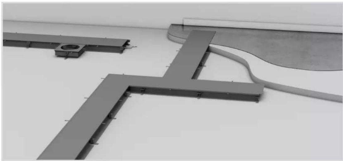
Architectural structural components including L-shaped beams and a curved beam, shown in grayscale (no text or symbols)Image 9: electraplan.BK
This height-variable system is used anywhere where it is not clear how the “final installation” will be and/or the highest level of flexibility is desired. Duct widths of up to 600 mm allow the duct to be used wherever high volumes of cables occur. This screed-flush duct is used in a shiny version in production halls, but also in office and administrative buildings with duct covers with floor covering stuck on. Its very low height means that the duct is also suitable for very flat screed heights of 30 mm or more.
On-floor duct system

natural_image
Interior architectural rendering of a modern room with wall-mounted fixtures and a curved staircase (no text or symbols visible)Image 10: electraplan.AK
For renovated properties or listed buildings, an on-floor duct is the perfect solution. Thanks to the range of moulded parts available for it, the electraplan.AK system is easy to assemble. Blind covers are screwed to the lower sections of the duct; these blind covers are angled towards the floor and flooring can be laid over them. Installation apertures in the cover allow installation units, supply units, floor connection columns or on-floor pedestals to be installed. See catalogue
Raised floor installation system

natural_image
Experimental setup with a perforated panel, connected tubing, and three metal components (no visible text or symbols)Image 11: electraplan.DB
Open plan offices or large-area call centres divided up into many computer workstations using partitions and which must remain structured cannot avoid this flexible system. This also applies to computer server rooms constructed with raised floors, which offer the greatest possible flexibility through their construction. In this way, completely networked power and data networks are integrated into showrooms or trade fair stands which are rebuilt according to requirements.
Cavity floor installation system

natural_image
Interior view of a modern kitchen or kitchen area with curved ceiling and wall-mounted electrical components (no visible text or symbols)Image 12: electraplan.HB
In cavity floors, prefabricated polystyrene or plastic shells are laid out on the raw ceiling and then cast with screed. In contrast to raised floors, in which individual plates can be exchanged as required, a cavity floor is a closed screed plate on stilts.
In a similar manner to the raised floor, wiring can be designed very flexibly using plug and play systems.
Basic principles of screed
Screed structure
The screed structure is a key precondition for the correct installation of underfloor systems. With screed-covered systems, it is essential that the screed thickness above the duct corresponds to the value stated in the standard, in order to avoid crack formation.
The screed is located above the load-bearing storey ceiling or above the floor plate and beneath floor covering.
The nominal screed thickness is dependent on the insulating layer, the individual load and the screed type. Refer to DIN EN 13813 for more information on the nominal screed thickness.
The minimum nominal thickness ^1 is regulated according to the hardness class (DIN EN 13813) for perpendicular loads ≤ 2 kN/m ^2 .
Under some circumstances, chemical or thermal loads may occur, which require additional measures to protect the installed system.
The electraplan.BK screed-flush duct systems and the BKSA underfloor sockets only receive their load capacity for correct use through being joined with the adjacent screed.
For this reason, the following points are important and must be observed:
- After the duct system has been permanently installed on the raw concrete, then the system may no longer be walked on or subjected to similar loads
- The duct system must form a composite system with the adjacent screed
With electraplan.BK, the following points must be particularly observed:
- The side profiles need to be supported with screed, in order to achieve a good static support in the screed. The screed is to be carefully worked and compacted
- The opened duct system may neither be walked on nor subjected to similar loads. Measured for the necessary protection must be taken in agreement with the construction management
1) For increased use and surface loads, appropriately increased minimum nominal thicknesses shall apply
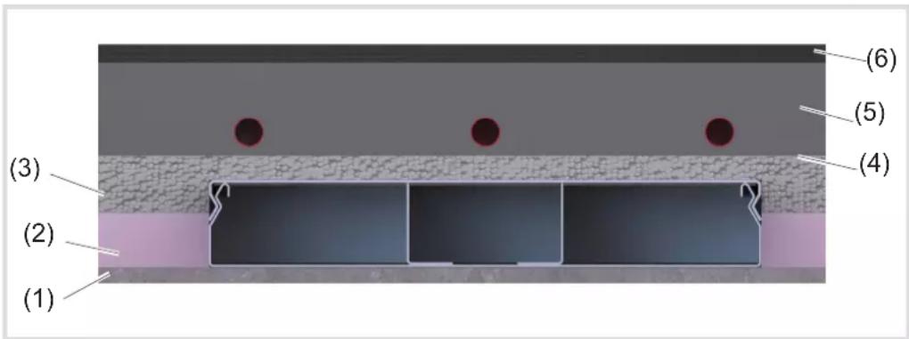
Image 13: General floor structure
(1) Raw ceiling / floor plate
(2) Thermal insulation (e.g. polystyrene)
(3) Impact noise insulation
(4) PE film
(5) Cement screed with underfloor heating
(6) Floor covering
Screed work
Ducts and accessory parts only obtain their full load capacity for correct use through the fixed composite with the screed. For this, the following preconditions are of importance:
- The duct system must be sealed before screed is applied
- All the system elements are permanently anchored on the raw ceiling
- The installed duct system may neither be walked on nor subjected to any other loads
– Any hollow spaces created must be filled with screed
- The duct system may only be subjected to loads after the screed has hardened and must be blocked off prior to this
– Screed deformations and shrinkages must be observed in advance
With a screed-covered duct, it is essential that the screed thickness above the duct corresponds to the value stated in the standard, in order to avoid crack formation.
The nominal screed thickness is dependent on the insulating layer, the individual load and the screed type. For more detailed information on screed types and the nominal screed thickness, refer to DIN EN 13318, DIN EN 13813, DIN EN18560. Here, under certain circumstances, chemical or thermal impacts may occur, which may require additional measures to protect the installed system.
Screed-flush ducts (BKF/D and BKW/D) and floor boxes (UDHx, UDBx, UDSx) must be levelled to the intended height before screed laying (construction side height line). The screed layer should check the levelling height.
Smooth and compress screed well on the screed-flush ducts and floor boxes (no insulation strip). Only this achieves the required load capacity.
The BKB/BKG screed-flush duct system is decoupled from the screed using an insulating strip, as it could otherwise lead to damage to the screed and/or floor covering.
Screed types
When selecting the screed structure, it is necessary to clarify which screed mortar types are possible for the application. There are difference types of screed mortars.
Flowing screed:
Before screed application, these tasks must be observed and completed:
- Duct system and boxes are to be weighed down --> Floating of the screed
- Duct system and boxes are to be sealed against the ingress of flowing screed and protected on the construction side
– Side profiles and film must be jacketed with sufficient screed.
- Avoid cavities
Aggressive screed:
When using aggressive screed types, all the metal parts must be insulated during construction using a chloride and alkali-free bitumen layer or other suitable means (VOB Part C).
Corrosion:
Corrosion on metallic underfloor components is reduced to a minimum when
- The maximum moisture content of screeds corresponds to DIN EN 1264-4.
- Underfloor ducts are ventilated sufficiently for drying.
Floor installation systems
Basic manual
:hager
Hot floor screed:
Screed-flush duct systems and boxes may not come into direct contact with the hot screed mass. With film lining, there must be an approx. 10 cm-thick layer of cement screed, for example, by the components for heat insulation. With metal lining and floor troughs, waterproofed corrugated card, for example, can be used for insulation. Screed-covered ducts must be protected against the hot screed mass with 2 - 3 layers of waterproofed corrugated card.
Avoid cavities! Hager is not liable for any damaged cause by improper installation on the duct system or the floor box in conjunction with hot screed!
Expansion pressure of the screed plate:
According to the size of the screed plate and the composition of the screen, it is possible that the boxes may press against the electraplan.BK duct whilst the screed is hardening. For this, Hager can offer a matching self-adhesive foam rubber strip (BKZM203), which is fitted in the upper profile area, in order to reduce the expansion pressure of the screed plate on the duct. The use of the foam rubber strip must be agreed with the screed layer.
Floor structure
A decisive criterion in the correct selection is the floor structure. The screed height specifies the amount of play for the underfloor installation. Different products and solutions are used, depending on the height. It is ever often the case that the screed height is even thinner for reasons of cost. Hager can offer a range of finished solutions for this. However, should the screed height be extremely low, then special, project-related special solutions can be provide assistance here.

Image 14: Floor structure
Floor structure 50 mm

natural_image
3D rendered diagram of a rectangular structure with colored blocks and a 50mm scale indicator (no text or symbols beyond the scale)The two hinged covers KDQ08x and KDE04x were developed specially for the requirements, in which only a screed height of 50 mm or more is available.
Thanks to their horizontally arranged socket outlets in the GBES2x device casing, the hinged covers are suitable anywhere where the screed height is only very low. Special solutions can also be used to install data technology in the two hinged covers.
Floor structure 75 mm

natural_image
3D rendering of a mechanical component with internal structure, labeled '75mm' at bottom (no other text or symbols)From a screed height of 75 mm, standard supply units with device carrier of type GTVR400, GTVR300 can be used for socket outlets or GTVD300, GTVD200 for data technology.
Here, a large selection of sizes and combination options are available.

natural_image
Exterior view of a modern office building (no signage)Floor structure 105 mm
Stainless steel cassettes can be used with floor structure heights of 105 mm or more. The stainless steel cassettes can be equipped with the standard device carriers in the same way as the supply units.
Here too, there is a large selection of sizes and combination options. If a higher load is required, the heavy duty variant is available in the same sizes.
Information on the floor covering and for the floor layer
Information on the floor covering
When selecting the floor covering materials, it should be noted that floor installation systems are subject to the impacts of payloads and must be classified using testing loads of 500 N up to 20,000 N, in accordance with DIN EN 500 85.
In so doing, dynamic bending of up to 6 mm and residual deformations of up to 3 mm shall not be considered faults. Evenness dimensions for finished floors can be found in DIN 18202 Tab. 3 Line 3.
Self-carrying layer thicknesses for facing concrete, artificial resin, mastic asphalts, as well tiles or natural stone can therefore prevent later crack formation of the covering with changing dynamic loads.
Even small bends can cause damage to thin, hard floor coverings, such as tiles. Thick floor coverings, such as granite plates, increase the load capacity of the underfloor system, producing a more beneficial load distribution.
Information for the floor layer
The floor covering, carpet, tiles, laminate, etc. to be laid must be installed correctly according to VOB Part C/DIN 18352, DIN 18353 and DIN 18365. In addition, possible trip points must be avoided using suitable measures, in accordance with the Workplaces Ordinance ArbStättV ASR A1.5/1.2 Floors of the German Federal Institute for Occupational Safety and Health.
Preconditions for laying floor coverings
Before the floor covering can be laid, the following conditions must be fulfilled:
- Dust and dirt must be removed from the floor ducts and universal floor boxes, in order to improve the adhesion of the floor coverings.
- Coverings made of wooden materials for covers must be treated on both sides, so that they do not warp. With single-sided adhesion, use double-sided carpet tape.
- With many wooden materials, it is wise to plan for expansion joints, which compensate for expansion and also shrinkage. These are then located, for example, along the side walls of floor ducts and on outer frames of cassettes.
- With floor coverings, observe the course of the surface structure.
- Long-tufted floor covers can get in the way when inserting the duct covers.
Laying floor covers on BKB / BKG ducts
When laying floor coverings on BKB and BKG ducts, particular attention must be placed to these two points:
- With hard floor coverings, such as wood or tiles, expansion joints must be planned for.
- With floor coverings that tend to fray, the edges should be sealed.
Laying floor covers on BKF(D) / BKW(D) ducts
- A covering joint cover (BKZBSA7011) should be preferred to the covering joint edge for lightly fraying textile floor coverings. These are available in 2.4 m lengths.
- Use the cut floor covering to lay the duct covering.
- Work hard floor coverings, such as wood or tiles, up to the inner side of the plastic profile.
- With hard floor coverings, such as wood or tiles, expansion joints must always be planned for.
- A PVC floor covering can be welded to the covering joint edge.
Special features for cassettes with covering joint edge
- Work hard floor coverings, such as wood or tiles, up to the cassette which has already been inserted. Always plan for an expansion unit to the supply unit.
- With hard coverings, an expansion joint should also be planned in the cover flap.
Determining the cable volume
A key point in the selection of the correct trunking is the cable volume, i.e. the quantity of cables that must be routed in the trunking. As cables cannot usually be routed in an absolutely straight line on account of their properties (mostly sold from reels), cables can thus not be located close together and in parallel in the duct system.

Image 15: Cable volume
To calculate the cable volume, not only the cable diameter must be used as a basis, but the formula (d)^2 must be included as a basis for calculation.
natural_image
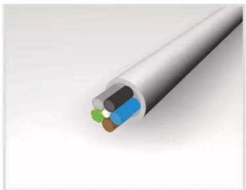
3D illustration of a cable with colored insulation layers (no text or symbols)Image 16: Determining the cable volume
On the next page, we have listed the space requirements/duct cross-section for the most common duct types.

The listed values are average values, which can vary from manufacturer to manufacturer.
Refer to the manufacturer's data for the exact values.
Use the following table for the correct selection of the duct size. In addition, these factors from the current DIN/VDE standards must be observed:
- Usable cross-section of the duct
- Filling factor
- Heating up of the routed cables
– Separation of heavy and weak current - Bend radii
| Art. number Art. designation Width | [mm] | Height min [mm] | Height max [mm] | Duct cross section [cm^2] ^2 | Number of cables (3 x 1.5 mm ^2 ) ^3 | |
| AKU1500401 On-floor duct base 150 40 X 60 24 | ||||||
| BKF400105 | On-floor duct, screed-flush with the film | 416 105 | 150 540 223 | |||
| BKW200060 | On-floor duct, screed-flush with the trough | 216 60 | 100 88 36 | |||
| BKFD150065 | On-floor duct, screed-flush with the film/sealing option | 170 65 | 110 121 50 | |||
| BKWD200090 | On-floor duct, screed-flush with the trough/sealing option | 220 90 | 130 143 59 | |||
| BKB25085 | Screed-flush floor duct with brush | 250 85 | X 212 45 | |||
| BKG30060 Screed-flush floor duct, closed 300 | 60 X 154 16 | |||||
| UK340483 | Underfloor duct, 3-compartment, screed-covered | 340 48 | X 163 65 | |||
| ^2) Values are rounded | ^3) Values are rounded / duct assignment of 50 % | |||||
Table 1: Duct size/duct cross-section/number of cables
i Further details on Table 1 can be found in the Appendix.
Bend radii
Bend radii are dealt with in the standard VDE 0298 (Part 3) and must be complied with when routing cables in floor installation systems.
Cable volume of most common installation cables
 | Jacketed cable, rigid | ||
| Designation | External diameter [mm] | Bending radius | Cable volume [cm2] |
| NYM-J 3G1.5 8.4 4xD 0.71 | |||
| NYM-J 3G2.5 9.6 4xD 0.92 | |||
| NYM-J 3G4 11.3 4xD 1.28 | |||
| NYM-J 3G6 12.8 4xD 1.64 | |||
| NYM-J 3G10 14.7 4xD 2.16 | |||
| NYM-J 3G16 19.0 4xD 3.61 | |||
| NYM-J 5G1.5 10.0 4xD 1.00 | |||
| NYM-J 5G2.5 12.0 4xD 1.44 | |||
| NYM-J 5G4 14.0 4xD 1.96 | |||
| NYM-J 5G6 15.5 4xD 2.40 | |||
| NYM-J 5G10 19.5 4xD 3.80 | |||
| NYM-J 5G16 23.4 4xD 5.48 | |||
Table 2: Cable volume, jacketed cable, rigid
 | Jacketed cable, flexible | ||
| Designation | External diameter [mm] | Bending radius | Cable volume [cm2] |
| H05VV-F 3G1.5 8.2 | 3xD 0.67 | ||
| H05VV-F 3G2.5 9.8 | 3xD 0.96 | ||
| H05VV-F 5G1.5 10 | 2 3xD 1.04 | ||
| H05VV-F 5G2.5 13 | 3xD 1.69 | ||
Table 3: Cable volume, jacketed cable, flexible
The data for the external diameter and cable volume is estimates and is rounded. Refer to the manufacturer's data for exact details.
 | IT data cables | ||||
| Designation | External diameter [mm] | Bending radius | Cable volume [cm2] | ||
| Cat 5e | 1x4xAWG 22/7 | shielded | 6.5 4xD 0.42 | ||
| Cat 6 | 4x2xAWG 23/1 | shielded | 7.4 4xD 0.55 | ||
| Cat 6 | 4x2xAWG 23/1 | unshielded | 6.4 4xD 0.41 | ||
| Cat 6a | 4x2x AWG 23/1 | U/UTP | 6.4 4xD 0.41 | ||
| Cat 6a | 4x2x/ AWG 23/1 | U/FTP | 7.2 4xD 0.52 | ||
| Cat 6a | 4x2x/ AWG 23/1 | F/FTP | 7.5 4xD 0.56 | ||
| Cat 6a | 4x2x/ AWG 23/1 | S/FTP | 7.4 4xD 0.55 | ||
| Cat 7a | 4x2x/ AWG 22/1 | S/FTP | 8.6 4xD 0.74 | ||
| Cat 7a | 4x2x AWG 26/7 flex | S/FTP | 5.8 4xD 0.34 | ||
| Cat 6 | 2x(4x2xAWG 23/1) | shielded | 7.4 x 15.0 4xD 1 | 1.10 | |
| Cat 6 | 2x(4x2xAWG 23/1) | unshielded | 6.4 x 12.8 4xD 8 | 1.19 | |
| Cat 6a | 2x (4x2x AWG23/1) | U/FTP | 7.4 x 15.0 4xD 1 | 1.10 | |
| Cat 6a | 2x (4x2x AWG23/1) | F/FTP | 7.5 x 15.2 4xD 1 | 1.40 | |
| Cat 6a | 2x (4x2x AWG23/1) | S/FTP | 7.4 x 15.0 4xD 1 | 1.10 | |
| Cat 7a | 2x (4x2x AWG22/1) | S/FTP | 8.6 x 17.5 4xD 1 | 5.05 | |
Table 4: Cable volume, data cables
 | Fibre optic cables | |||
| External diameter [mm] | Bending radius | Cable volume [cm2] | ||
| Internal cables 1 x 6 6.5 15xD 0.42 | ||||
| 1 x 8 6.5 | 15xD 0.42 | |||
| 1 x 12 6.5 | 15xD 0.42 | |||
| 1 x 24 | 7 | 15xD 0.49 | ||
| 2 x 12 8.3 | 10xD 0.69 | |||
| 4 x 12 8.6 | 10xD 0.74 | |||
| 6 x 12 8.6 | 10xD 0.74 | |||
| 8 x 12 9.9 | 10xD 0.98 | |||
| 12 x 12 1 | 1.4 | 10xD 1.30 | ||
| Duplex cables | 2 x 1 | 5.6 x 3.2 | 5xD | 1.79 |
Table 5: Cable volume, fibre optic cables
The data for the external diameter and cable volume is estimates and is rounded. Refer to the manufacturer's data for exact details.
Further details on the duct area and cable volume can be found in the "Appendix"
Power supply and device installation units
Supply units VQ/VE/VR
The supply units are the tried-and-trusted solution for office installations with carpeted floors. They are available in plastic or metal. The solution is not connected to the substrate, but is clamped to the UDB floor box or directly onto the screed using the universal fastening claw.

natural_image
Simple diagram of a rectangular device with a horizontal line and cable, placed on a textured gray surface (no text or symbols)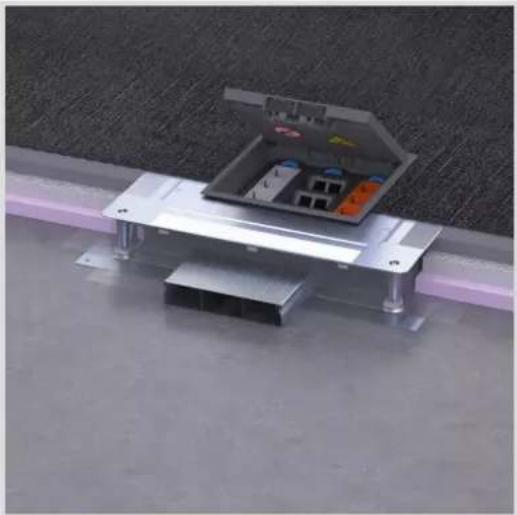
natural_image
Metallic electronic device with open case and internal components, placed on a concrete floor (no visible text or symbols)| Supply units | |
| Forms | |
| Nominal sizes Q12, R12, R10,E09, Q06, R06, | |
| Number of socket outlets | 12,10,9,6 |
| Floor covering depth 5 mm, 12 mm | |
| Version Blank, cable outlet | |
| Minimum installation depth | 60 mm, 75 mm, 82 mm |
| Material Plastic, stainless steel | |
| Colours RAL 7011, RAL 9005, stainless steel | |
Table 6: Overview of supply units
Stainless steel cassette EKQ/EKR/EKSQ/EKSR
The cassettes can be levelled to be flush with the height of the floor and can be completely decoupled from the socket base. Cassettes are particularly suitable for floor coverings like tiles or parquet. Various versions are available for dry/moist and wet cleaned floor coverings. The stainless steel cassettes offer continuous quality and also look attractive.
Levellable stainless steel cassettes for dry or moist cleaned floors are available in two versions. The minimum installation depth from the top edge of the finished floor is 100 mm for the blank stainless steel cassette and between 105 and 115 mm for stainless steel cassettes with device casing. The device casings can be lowered in stages down to 18 mm and a mounting device for a locking extension is possible.

natural_image
Close-up of a tiled floor with a black cable and a small electronic device attached to the surface (no text or symbols visible)
natural_image
Metallic open electrical enclosure with internal compartments and mounting base, placed on a tiled floor (no text or symbols visible)| Stainless steel cassette EKQ/EKR/EKSQ/EKSR | |
| Forms | |
| Nominal sizes Q12, R12, Q06, R06, | |
| Number of socket outlets | 12.6 |
| Floor covering depth 23 mm, 38 mm | |
| Version Blank, cable outlet, cone | |
| Minimum installation depth | 100 mm, 105 mm, 115 mm |
| Material Stainless steel | |
| Colours Stainless steel | |
Table 7: Overview of stainless steel cassettes
Wet-cleaned supply units VANR

natural_image
Close-up of a circular metal plate with a black central component and two wires attached, placed on a tiled floor (no text or symbols visible)The VANR wet-cleaned supply units are suitable for greater loads, such as car showrooms, and especially for floor coverings such as tiles or stone floors. The supply units are made of aluminium and are available with various cover versions.
| Wet-cleaned supply unit VANR | |
| Forms | |
| Nominal sizes R12, R02 | |
| Number of socket outlets | 12/6 |
| Floor covering depth 3 | mm, none |
| Version Tube | |
| Minimum installation depth | 90 mm |
| Material Aluminium | |
| Colours Aluminium, Aluminium/RAL9005, Aluminium/Al-uminium | |
Table 8: Overview of wet cleaned supply units
UD floor box set UDKPQ

natural_image
Exterior view of a wooden floor with exposed brick and concrete panels (no text or symbols)The UD floor box set series is supplied as a complete installation unit. The installation unit consists of a floor box as a screed lining and either a stainless steel cassette or supply unit for device installation. The individual elements for device installation are included in the scope of delivery. The floor box is installed directly on the raw concrete and connected with flexible installation tubes. In addition, if necessary, the floor tank can be combined individually from the individual parts and assembled on the construction site.
| UD floor box set | |
| Forms | |
| Nominal sizes Q06 | |
| Number of socket outlets | 6 |
| Floor covering depth 5 | mm, 23 mm |
| Version Cable outlet | |
| Minimum installation depth | 95 mm, 105 mm |
| Material Plastic/stainless steel | |
| Colours Stainless steel, RAL 7011, RAL 9005 | |
Table 9: Overview, UD floor box set
Floor socket outlets BSR02

natural_image
Close-up of a circular component with black wires attached to a tiled floor (no text or symbols visible)The BS floor socket outlets are particularly suitable where aesthetics, a high load capacity and versatile functionality are required.
Handling is both safe and simple: Insert the pipelines into the installation space. The installation space is closed with a cover.
The installation box of the floor socket outlets is pre-equipped with two sockets outlets. Next to the socket outlets, there is space for a maximum of two connection sockets for network applications.
| Floor socket outlet BSR02 | |
| Forms | |
| Nominal sizes R02 | |
| Number of socket outlets | 2 |
| Floor covering depth None | |
| Version Cable outlet, cone | |
| Minimum installation depth | 86 mm |
| Material Plastic, die-cast zinc | |
| Colours Old copper, old brass, silver, RAL 7011, RAL 9005 | |
Table 10: Overview, floor socket outlet BS
Hinged cover for flat floor mounting KDQ/KDE

natural_image
Simple diagram of a rectangular device with wires attached, placed on a textured surface (no text or symbols)Special solutions are required for low assembling heights. The KDQ/KDE series contains hinged covers special for very flat floor mountings.
With the help of a special socket outlet GBExx, this series can allow power supplies, even with a floor mounting of 50 mm of more.
| Supply units | |
| Forms | |
| Nominal sizes Q08, E04 | |
| Number of socket outlets | 8/4 |
| Floor covering depth 5 | mm, 8 mm, 12 mm |
| Version Blank, cable outlet | |
| Minimum installation depth | 50 mm, 60 mm |
| Material Plastic | |
| Colours RAL 7011, RAL 9005 | |
Table 11: Overview, hinged cover for flat floor structure
IP degree of protection
The IP degree of protection of floor installation systems is tested and categorised according to EN 50085-2-2 and the type of floor care according to EN 60529. Floor installation systems are only intended for use in interior areas.
The supply unit is tested in its used and unused states to determine the degree of protection. All the duct systems and supply units must fulfil at least the IP 20 degree of protection in the used and unused states.
In addition to the categorisation of the IP degree of protection, with wet cleaning, it must be ensured that, in the used state, all the openings through which cables exit must be at least 10 mm above the floor surface.
The floor covering cleaning type - dry, moist, wet - is the decisive factor in the selection of the suitable supply unit.
Dry cleaning
Dry cleaned floors are primarily textile floor covers, which are cleaned by sucking up the dirt (with small amounts of liquids or completely without). Should a cleaning solution be used, then it must be dosed as low as possible, in order to prevent puddle formation or the floor covering being soaked through.
Moist cleaning
Smooth floor coverings such as linoleum, PVC, laminate, parquet or polished stone floors fulfil the requirements for moist care of the floor covering. The building cleaning trade defines this type of floor covering as a manner of binding dust with moistened or prepared cleaning textiles.
Wet cleaning
Wet cleaning is primarily used with stone coverings, tiles, ceramic floors, linoleum and PVC. This type of cleaning removes particularly tough and sticky contamination. In so doing, as much cleaning liquid is applied in the first cleaning operation with cleaning textiles as is required to soften contamination and release it. In a second operation, this liquid is wiped up again, together with the contamination, using cleaning textiles.

Image 17: Arrangement of IP code
| Component Digits or letter Meaning for the protection of the resource | Meaning for the protection of people | ||
| Code letters IP - - | |||
| First code digit Against the ingress of solid foreign bodies | Against access to dangerous parts with | ||
Table 12: Components of the IP code and their meaning
IK degree of impact resistance
The IK code according to (DIN) EN 50102 is a dimension for knock and impact loads. The IK code specifies the maximum mechanical load of housings of electrical resources/equipment.
Mechanical/thermal loads
Mechanical and thermal loads (load) are forces impacting on the floor installation duct system from outside. With improper installation and use, mechanical forces can cause deformations and destruction. Thermal forces, cause by excessive sunlight and/or heated screeds, cause the installed materials to expand. This can lead to crack formation.
Loads and their impacts on installation systems
Floor installation duct systems are exposed to the traffic loads typical for the building. They must withstand the loads occurring at the place of use and, in so doing, maintain their function. The loads can be triggered by different factors:
- Being walked over by people
- Stands of office furniture
- Loads from vehicles and means of transport
The load is applied directly to the floor or the entire ceiling construction. This means that the load also has a direct influence on the installation floor installation systems.
Standardisation and testing
Standardisation
The EN 50085 series of standards specifies the general requirements for electrical installation duct systems. In particular, Part 2-2 describes the requirements for floor installation systems and took effect in July 2009.
The standard is divided up into two sections:
– Erector specifications
The electrical installation engineer is usually responsible for compliance with the requirements described in the erector specifications.
– Device testing specifications
The device test specifications specify the testing criteria of the products/devices. The manufacturer of the products/device is responsible for compliance with it.
Device testing specifications
- Define the function of the product/device
- Define the load capacity of the product/device
- Define the area of use of the product/device
- Are primarily responsible for the safety of the product/device (e.g. protection against electric shocks)
Classification of floor installation systems
EN 50085-1, as a general section for electrical installation duct systems, and EN 50085-2-2, as a system-specific section for floor installation systems, prescribe a classification of the products.
This standardises product properties across Europe. For the first time, a standard for installation systems has also been given an optional load test for vertical loads that impact over a large area (heavy duty).
| Classification according to EN 50085-1 | |
| 6.1 Based on material | |
| 6.2 Based on impact resistance | |
| 6.3 Based on temperature | |
| 6.4 Based on resistance to flame propagation | |
| 6.5 Based on electrical conductivity | |
| 6.6 Based on electrical insulating properties | |
| 6.7 Based on degrees of protection afforded by housing/casing in accordance with EN 0529:1991 | |
| 6.8 Based on protection against corrosive or contaminated substances | |
| 6.9 Based on fastening type for system duct cover | |
| 6.10 Based on electrical protection separation | |
| Classification according to EN 50085-2-2 | |
| 6.101 Based on type of floor care | |
| 6.102 Based on resistance to vertical loads applied to a small area ( +/-13 mm) | |
| 6.103 Based on resistance to vertical loads applied to a large area ( +/-130 mm) |
Table 13: Classification according to EN 50085
Testing
Load testing of electrical installation duct systems
Electrical installation duct systems for electrical installations must conform with the standard (DIN) EN 50085-2-2.
The standard states that electrical installation duct systems must possess sufficient mechanical stability.
Load capacity for screed-flush duct systems (BK) and their installation units
(DIN) EN 50085-2-2 defines load classes for two applications.
Tests are carried out according to:
- 6.102 with a stamp (∅ 13 mm) for standard applications (Image 18, left)
- 6.103 with a plate (∅ 130 mm) for high loads (Image 18, right)

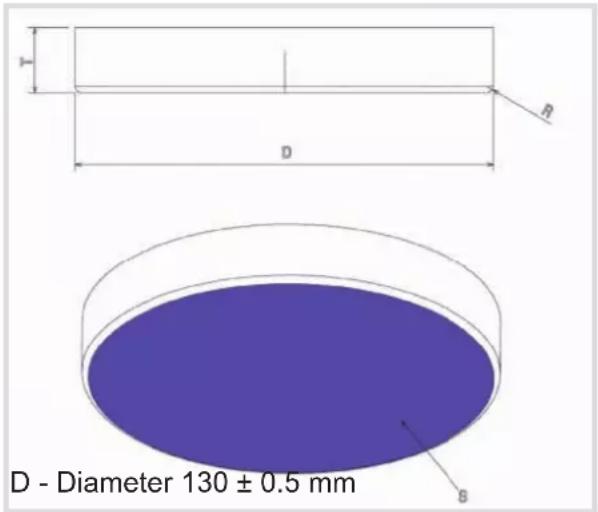
Image 18: Test die (left) / test plate (right)
| Testing Load class (DIN) EN 50085 | ||
| Standard application (tested with test die 13 mm) | 6.102.1 500 N | |
| 6.102.2 750 N | ||
| 6.102.3 1000 N | ||
| 6.102.4 1500 N | ||
| 6.102.5 2000 N | ||
| 6.102.6 2500 N | ||
| 6.102.7 3000 N | ||
| High load (tested with a test plate ∅ 130 mm) | 6.103.1 2000 N | |
| 6.103.2 3000 N | ||
| 6.103.3 5000 N | ||
| 6.103.4 10000 N | ||
| 6.103.5 15000 N | ||
Table 14: Load classes according to (DIN) EN 50085-2-2
The testing of the floor installation systems with high load requirements may be dealt with in the standard (DIN) EN 500085-2-2, but the bending during the test (6 mm) permitted in the standard and that after the test ( ≤ 3 mm) is not practical. Bending of this magnitude inevitably leads to damage to hard floor coverings (e.g. tiles).
Floor installation systems
Basic manual
:hager
Load capacity of screed-covered floor installation systems
Screed-covered duct systems are only subjected to a load during the installation phase. After this, ducts are “protected” by the screed layer and the traffic loads are distributed across the screed.
In general, it is considered that all screed-covered duct systems must be constructed in such a way so as to be stable enough to withstand the loads occurring on the construction site during storage, transport and processing.
Erector specifications
The erector specifications according to DIN VDE describe a wide range of points, which the electrician must observe and comply with during the construction and installation of the floor installation systems.
The erector specifications are particularly important for:
– Safety (protection against electric shock)
– Maintenance of function - function maintenance
– Electromagnetic compatibility
- Fire protection
The following section explains some of the key points from the erector specifications:
Protection against electric shock
For the erection of a cable system with electrical installation duct systems, multiple standards from the VDE 0100 series are important, in particular:
- DIN VDE 0100-410:2018-10, which describes the protection measures for protection against electric shock, as well as
– DIN VDE 0100-520:2013-06, which describes the selection and erection of cable systems.
Electrical installation duct systems are a component part of the cable system (Section 520.3.1 in DIN VDE 0100-520) and thus of the electrical installation. They are thus not covered by Section 411.3.1.2 of DIN VDE 0100-410.
In Section 410, DIN VDE 0100-410 refers to DIN EN 61140 (VDE 0140-1), which, as a basic safety standard, describes the shared requirements for protection against electric shock for electrical systems and resources. Accordingly, the basic rule of protection against electric shock is that dangerous active parts may not be touchable and touchable, electrically conductive parts, may not become dangerous active parts, neither under normal conditions, nor under conditions of individual errors.
In addition, it describes that safety measures against electric shocks must consist of a suitable combination of two independent protective measures - of a basic protection measure and an error protection measure.
In a cable system, a basic protection measure would typically be basic insulation (e.g. wire insulation) or a protective housing.
An error protection measure is frequently the automatic switch-off of the power supply (Section 411) or double insulation (Section 412).
Table A.52.1 of DIN VDE 0100-520 defines that insulated cables (wire cables) may only be used in the electrical installation duct systems to be opened (including underfloor systems) if the duct system offers at least the protection rating IP4x and can only be opened with a tool. Jacketed cables can be used without restrictions.
In addition, Section 526.5 of DIN VDE 0100-520 defines that electrical connections must be made in suitable jacketing (e.g. boxes or in resources, if planned).
Metallic duct systems must be included in the safety measures and the equipotential bonding. This guarantees protection against electric shock according to DIN VDE 0100-410 and electromagnetic compatibility (EMC) according to EN 50310, EN 50173, EN 50174-2.
Mechanical load of cables
Floor installation systems
Basic manual
According to DIN VDE 0298, specific values for strain relief and bend radii may not be under-shot during the routing of heavy current cables and data cables. The standard also describes the permitted types of fastenings of cables using clips and their strain reliefs.
Separation of different services
DIN VDE 0100-520 states that cables of different voltage classes may only be installed together in a routing system if all the cables have protective insulation against the highest occurring voltage. Separating webs can be used to separate the different cables, as can the guarantee of a sufficient spacing.
Fire protection
The avoidance of fires, particularly in public buildings, is the main aim of fire protection. The spread of fire and particularly of smoke into other fire sections must be prevented with all the means available for a sufficiently long period of time. This provides the opportunity to take escape, rescue and extinguishing measures.
Fire protection measures should be taken on duct systems connecting/crossing fire sections, escape and rescue routes. The directives for cable systems (M)LAR system floors (M)SysBör regulate this in more detail.
The main causes for a fire on heavy current cables are:
- Incomplete short circuits or ground faults, e.g. on mechanically or thermally damaged cables
- Incorrect electrical connections, e.g. through a loose contact
- Heat build-ups
Equipotential bonding
The certified floor installation system must offer the option of being included in the equipotential bonding.
All the Hager underfloor cable duct systems are constructed in such a way that the connection and inclusion in the equipotential bonding is possible without major work.
The earthing clamp BKZSAK00 is used to include the duct system in the equipotential bonding. The earthing clamp is inserted in the existing grooves and screwed tight. The terminal area is designed for a conductor cross-section of up to 4 mm ^2 .
Touchable, electrically conductive electrical installation duct systems are not included in the protective equipotential bonding (see Section 411.3.1.2 of DIN VDE 0100-410) and thus are not to be used as an error protection measure. However, they can, for example, for EMC reasons, be included in the functional equipotential bonding or in the additional protective equipotential bonding and in the lightning protection equipotential bonding.
Conversely, this means that the resources installed within the electrical installation duct system must automatically fulfil the requirements for basic protection and error protection. This also includes the cable systems according to DIN VDE 410 Section 412.2.4.
The floor installation system is an electrical installation duct system and does not fulfil the requirements for double insulation (VDE 0100-410 Section 412). This means that the use of conductors with basic protection (e.g. H07V-K) is not permitted. At least jacketed cables (e.g. NYM-J) must be used, which end or are connected in suitable jackets (e.g. in boxes or in resources). Strain relief must always be provided.
Inter-unit working
On today's construction sites, inter-unit working is a matter of course and the associated intensive communication with the neighbouring units essential.
For this reason, we at Hager recommend, at the beginning of the construction phase and in agreement with the construction management, co-ordination between electricians and the conterminous inter-unit working, in order to guarantee a flawless procedure for installing the floor installation system and the quality of the entire construction section.
Inter-unit working - Screed work
Screed-flush cable duct systems and the connector boxes of the screed-covered duct system are a binding draw-off gauge for the screed. The levelling height of the system components is aligned to the structural specifications of the construction management (observe the cutting check).
The screed layer must work, compact and draw off the screed carefully in the area of the connector boxes and cable trunking. Screed can be destroyed through crack formation. Screed-flush systems and system components may not be subjected to loads before the screed has finally hardened, in order to avoid crack formation in the screed.
General information for screed layers
The duct system levelled to the target screed height and the levelled floor boxes may not be subject to a load, walked on or opened before the target screed stability is reached. With covers with snap fastenings, the transport lock screws of the cover may only be removed when the screed has hardened. Screed-flush ducts and floor boxes must be levelled to the intended height before screed laying (construction side height line). The screed layer should check the levelling height. Smooth and compress screed well on the screed-flush ducts and floor boxes. Only this achieves the required load capacity. All the duct openings larger than the grain size used must be sealed.
Inter-unit working - Floor covering work
The company responsible for the floor covering work is also responsible for the exact routing and adaptation of the floor covering to the connector boxes and cable outlets.
The exact joint dimensions must be clarified in advance with the construction management.
The covers of the screed-flush connector boxes must also be covered with floor covering.
Any carpet used must be permanently laid and must be resistant to cutting.
Inter-unit working - Building cleaning
In particular during the initial cleaning of the floor surfaces, building installation units and installation spaces must be carefully cleaned of construction dust and other impurities, so that their function does not lead to impairments later.
During the use phase, building installation units must be checked for their intended use and possible damage, in order to avoid later damage (Facility Management / Electricians).
In particular, device installation units for wet cleaned floors are to be maintained regularly and the seals checked for their function. For this, it is necessary to relubricate the seal regularly (Facility Management / Electricians).
Sound protection and impact noise
The aim of sound protection in buildings is to prevent sound from being transferred between various rooms and/or floors. The DIN 4109 standard contains guidelines on sound and impact noise levels in residential buildings. Impact noise con sists of two types of sound.
Airborne sound travels through the air, whereas structure-borne sound travels through solid bodies.
Standard DIN 4109 specifies noise limits L_n,w that must not be exceeded in certain areas of application.
Examples of segment-related noise limits:
- Office buildings: Residential dividing ceilings and ceilings between third-party office rooms L_nw ≤ 53 dB
- Recreation rooms and hotels (increased sound protection requirements): L_n,w ≤ 46 dB
The following always applies: The lower the values, the better the impact noise insulation is. The value can be reduced, for instance, by laying a floor covering (such as carpet). The transfer of impact noise can also be reduced by laying the screed on an insulation layer ("floating screed").
Impact noise reduction for floor installation systems
Reducing the transfer of impact noise is also relevant when laying underfloor installations. A test institute was therefore engaged to measure the impact noise reduction in selected Hager products. The requested test consisted of the measurement of the vertical spread of the structure-borne sound, in other words the transmission of sound between floors.
Müller-BBM GmbH measured the impact noise reduction in the ceiling test station in accordance with the DIN EN ISO 10140 standard and evaluated the findings in accordance with the ISO 717-2 standard.
The results of the measurement of the impact noise reduction are summarised below for the floor duct and the stainless steel cassette.
The installation of the floor duct has no significant influence on the impact noise reduction of the sc reed.
The installation of the stainless steel cassette has no significant influence on the impact noise reduction of the sc reed.
▶ You can find detailed information and an evaluation of the impact noise at www.hager.de.
Appendix
Overview of floor installation systems - cable assignment
| Cable assignment, BKF ducts | ||||||
 | ||||||
| Ducts | Nominal dimension | External width a [mm] | Duct height b max. [mm] | Levelling range [mm] | Usable cross-section [cm^2] | Max. cable as-signment ∅ 11 mm Filling level 0.5 |
| BKF150045 150 | 166 70 45 | -70 77 31 | ||||
| BKF150065 150 | 166 110 65 | -110 121 | 50 | |||
| BKF150105 150 | 166 150 | 105-150 165 | 68 | |||
| BKF150145 150 | 166 190 | 145-190 209 | 86 | |||
| BKF200045 200 | 216 70 45 | -70 112 46 | ||||
| BKF200065 200 | 216 110 65 | -110 176 | 72 | |||
| BKF200105 200 | 216 150 | 105-150 240 | 99 | |||
| BKF200145 200 | 216 190 | 145-190 304 | 125 | |||
| BKF250045 250 | 266 70 45 | -70 147 60 | ||||
| BKF250065 250 | 266 110 65 | -110 231 | 95 | |||
| BKF250105 250 | 266 150 | 105-150 315 | 130 | |||
| BKF250145 250 | 266 190 | 145-190 399 | 164 | |||
| BKF300045 300 | 316 70 45 | -70 182 75 | ||||
| BKF300065 300 | 316 110 65 | -110 286 | 118 | |||
| BKF300105 300 | 316 150 | 105-150 390 | 161 | |||
| BKF300145 300 | 316 190 | 145-190 494 | 204 | |||
| BKF350045 350 | 366 70 45 | -70 217 89 | ||||
| BKF350065 350 | 366 110 65 | -110 341 | 140 | |||
| BKF350105 350 | 366 150 | 105-150 465 | 192 | |||
| BKF350145 350 | 366 190 | 145-190 589 | 243 | |||
| BKF400045 400 | 416 70 45 | -70 252 104 | ||||
| BKF400065 400 | 416 110 65 | -110 396 | 163 | |||
| BKF400105 400 | 416 150 | 105-150 540 | 223 | |||
| BKF400145 400 | 416 190 | 145-190 684 | 282 | |||
| BKF500045 500 | 516 70 45 | -70 322 133 | ||||
| BKF500065 500 | 516 110 65 | -110 506 | 209 | |||
| BKF500105 500 | 516 150 | 105-150 690 | 285 | |||
| BKF500145 500 | 516 190 | 145-190 874 | 361 | |||
| BKF600045 600 | 616 70 45 | -70 392 161 | ||||
| BKF600065 600 | 616 110 65 | -110 616 | 254 | |||
| BKF600105 600 | 616 150 | 105-150 840 | 347 | |||
| BKF600145 600 | 616 190 | 145-190 1064 | 439 | |||
Cable assignment, BKW ducts

| Ducts | Nominal dimension | External width [mm] | Drawing height [mm] | Levelling range [mm] | Usable cross-section [cm2] | Max. cable assignment ∅ 11 mm Filling level 0.5 |
| BKW150040 | 150 166 28 | 40 - 60 37,5 | 15 | |||
| BKW150050 | 150 166 38 | 50 - 70 50,9 | 21 | |||
| BKW150060 | 150 166 48 | 60 - 100 64,3 | 26 | |||
| BKW150070 | 150 166 58 | 70 - 110 77,7 | 32 | |||
| BKW200060 | 200 216 48 | 60 - 100 88,3 | 36 | |||
| BKW200070 | 200 216 58 | 70 - 110 106,7 | 44 | |||
| BKW200080 | 200 216 68 | 80 - 120 125,1 | 51 | |||
| BKW200090 | 200 216 78 | 90 - 130 143,5 | 59 | |||
| BKW250060 | 250 266 48 | 60 - 100 112,3 | 46 | |||
| BKW250070 | 250 266 58 | 70 - 110 135,7 | 56 | |||
| BKW250080 | 250 266 68 | 80 - 120 159,1 | 65 | |||
| BKW250090 | 250 266 78 | 90 - 130 182,5 | 75 | |||
| BKW300060 | 300 316 48 | 60 - 100 136,3 | 56 | |||
| BKW300070 | 300 316 58 | 70 - 110 164,7 | 68 | |||
| BKW300080 | 300 316 68 | 80 - 120 193,1 | 79 | |||
| BKW300090 | 300 316 78 | 90 - 130 221,5 | 91 | |||
| BKW350060 | 350 366 48 | 60 - 100 160,3 | 66 | |||
| BKW350070 | 350 366 58 | 70 - 110 193,7 | 80 | |||
| BKW350080 | 350 366 68 | 80 - 120 227,1 | 93 | |||
| BKW350090 | 350 366 78 | 90 - 130 260,5 | 107 | |||
| BKW400060 | 400 416 48 | 60 - 100 184,3 | 76 | |||
| BKW400070 | 400 416 58 | 70 - 110 222,7 | 92 | |||
| BKW400080 | 400 416 68 | 80 - 120 261,1 | 107 | |||
| BKW400090 | 400 416 78 | 90 - 130 299,5 | 123 | |||
| BKW500060 | 500 516 48 | 60 - 100 232,3 | 96 | |||
| BKW500070 | 500 516 58 | 70 - 110 280,7 | 116 | |||
| BKW500080 | 500 516 68 | 80 - 120 329,1 | 136 | |||
| BKW500090 | 500 516 78 | 90 - 130 377,5 | 156 | |||
| BKW600060 | 600 616 48 | 60 - 100 280,3 | 115 | |||
| BKW600070 | 600 616 58 | 70 - 110 338,7 | 139 | |||
| BKW600080 | 600 616 68 | 80 - 120 397,1 | 164 | |||
| BKW600090 | 600 616 78 | 90 - 130 455,5 | 188 |
Cable assignment, BKFD ducts

| Ducts | Nominal dimension | External width [mm] | Duct height max. [mm] | Levelling range [mm] | Usable cross-sec-tion [cm2] | Max. cable as-signment ∅ 11 mm Filling level 0.5 |
| BKFD150045 150 | 170 70 | 45-70 77 31 | ||||
| BKFD150065 150 | 170 110 | 65-110 121 50 | ||||
| BKFD150105 150 | 170 150 | 105-150 165 68 | ||||
| BKFD150145 150 | 170 190 | 145-190 209 86 | ||||
| BKFD200045 200 | 220 70 | 45-70 112 46 | ||||
| BKFD200065 200 | 220 110 | 65-110 176 72 | ||||
| BKFD200105 200 | 220 150 | 105-150 240 99 | ||||
| BKFD200145 200 | 220 190 | 145-190 304 125 | ||||
| BKFD250045 250 | 270 70 | 45-70 147 60 | ||||
| BKFD250065 250 | 270 110 | 65-110 231 95 | ||||
| BKFD250105 250 | 270 150 | 105-150 315 130 | ||||
| BKFD250145 250 | 270 190 | 145-190 399 164 | ||||
| BKFD300045 300 | 320 70 | 45-70 182 75 | ||||
| BKFD300065 300 | 320 110 | 65-110 286 118 | ||||
| BKFD300105 300 | 320 150 | 105-150 390 161 | ||||
| BKFD300145 300 | 320 190 | 145-190 494 204 | ||||
| BKFD350045 350 | 370 70 | 45-70 217 89 | ||||
| BKFD350065 350 | 370 110 | 65-110 341 140 | ||||
| BKFD350105 350 | 370 150 | 105-150 465 192 | ||||
| BKFD350145 350 | 370 190 | 145-190 589 243 | ||||
| BKFD400045 400 | 420 70 | 45-70 252 104 | ||||
| BKFD400065 400 | 420 110 | 65-110 396 163 | ||||
| BKFD400105 400 | 420 150 | 105-150 540 223 | ||||
| BKFD400145 400 | 420 190 | 145-190 684 282 | ||||
| BKFD500045 500 | 520 70 | 45-70 322 133 | ||||
| BKFD500065 500 | 520 110 | 65-110 506 209 | ||||
| BKFD500105 500 | 520 150 | 105-150 690 285 | ||||
| BKFD500145 500 | 520 190 | 145-190 874 361 | ||||
| BKFD600045 600 | 620 70 | 45-70 392 161 | ||||
| BKFD600065 600 | 620 110 | 65-110 616 254 | ||||
| BKFD600105 600 | 620 150 | 105-150 840 347 | ||||
| BKFD600145 600 | 620 190 | 145-190 1064 439 | ||||
| Cable assignment, BKWD ducts | ||||||
 | ||||||
| Ducts | Nominal dimension | External width [mm] | Drawing height [mm] | Levelling range [mm] | Usable cross-sec-tion [cm2] | Max. cable as-signment∅ 11 mmFilling level 0.5 |
| BKWD150040 150 | 170 28 | 40-60 37,5 15 | ||||
| BKWD150050 150 | 170 38 | 50-70 50,9 21 | ||||
| BKWD150060 150 | 170 48 | 60-100 64,3 26 | ||||
| BKWD200060 200 | 220 48 | 60-100 88,3 36 | ||||
| BKWD200070 200 | 220 58 | 70-110 106,7 44 | ||||
| BKWD200080 200 | 220 68 | 80-120 125,1 51 | ||||
| BKWD200090 200 | 220 78 | 90-130 143,5 59 | ||||
| BKWD250060 250 | 270 48 | 60-100 112,3 46 | ||||
| BKWD250070 250 | 270 58 | 70-110 135,7 56 | ||||
| BKWD250080 250 | 270 68 | 80-120 159,1 65 | ||||
| BKWD250090 250 | 270 78 | 90-130 182,5 75 | ||||
| BKWD300060 300 | 320 48 | 60-100 136,3 56 | ||||
| BKWD300070 300 | 320 58 | 70-110 164,7 68 | ||||
| BKWD300080 300 | 320 68 | 80-120 193,1 79 | ||||
| BKWD300090 300 | 320 78 | 90-130 221,5 91 | ||||
| BKWD350060 350 | 370 48 | 60-100 160,3 66 | ||||
| BKWD350070 350 | 370 58 | 70-110 193,7 80 | ||||
| BKWD350080 350 | 370 68 | 80-120 227,1 93 | ||||
| BKWD350090 350 | 370 78 | 90-130 260,5 107 | ||||
| BKWD400060 400 | 420 48 | 60-100 184,3 76 | ||||
| BKWD400070 400 | 420 58 | 70-110 222,7 92 | ||||
| BKWD400080 400 | 420 68 | 80-120 261,1 107 | ||||
| BKWD400090 400 | 420 78 | 90-130 299,5 123 | ||||
| BKWD500060 500 | 520 48 | 60-100 232,3 96 | ||||
| BKWD500070 500 | 520 58 | 70-110 280,7 116 | ||||
| BKWD500080 500 | 520 68 | 80-120 329,1 136 | ||||
| BKWD500090 500 | 520 78 | 90-130 377,5 156 | ||||
| BKWD600060 600 | 620 48 | 60-100 280,3 115 | ||||
| BKWD600070 600 | 620 58 | 70-110 338,7 139 | ||||
| BKWD600080 600 | 620 68 | 80-120 397,1 164 | ||||
| BKWD600090 600 | 620 78 | 90-130 455,5 188 | ||||
| Cable assignment, BKB ducts | |||||
 | |||||
| Ducts | Duct width [mm] | Duct height [mm] | Version | Usable cross-section [cm2] | Max. cable as-signment ∅ 11 mm Filling level 0.5 |
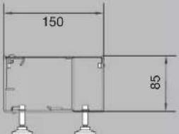
| BKB15085 150 | 85 2-compartment | 10000 28 | |||
| BKB25085 250 | 85 2-compartment | 21250 45 | |||
| Cable assignment, BKG ducts | |||||||
 | |||||||
| Ducts | Nominal dimension [mm] | External width [mm] | Duct height without levelling screw [mm] | Usable cross-section [cm2] Duct height incl. levelling screw [mm] | Version | Usable cross-sec-tion [cm2] | Max. cable assign-ment ∅ 11 mm Filling level 0.5 Internal levelling |
| BKG20060 | 200 200 | 60,3 73 | 2-compartment | 104.7 8 | |||
| BKG30060 | 300 300 | 60,3 73 | 3-compartment | 154.2 16 | |||
| BKG40060 | 400 400 | 60,3 73 | 3-compartment | 214.2 37 | |||
| BKG50060 | 500 500 | 60,3 73 | 4-compartment | 263.7 50 | |||
| BKG30080 | 300 300 | 80,3 93 | 3-compartment | 205.6 28 | |||
| BKG40080 | 400 400 | 80,3 93 | 3-compartment | 285.6 60 | |||
| BKG50080 | 500 500 | 80,3 93 | 4-compartment | 351.6 77 | |||
Cable assignment, UK ducts

| Ducts Duct | width [mm] | Duct height [mm] | Version Dimensions, compartments [mm] | Usable cross-sec-tion [cm^2] | Max. cable as-signment ∅ 11 mm Filling level 0.5 |
| UK190282 190 | 28 | 2-compartment | 75/115 53,2 21(8 / 13) | ||
| UK190283 190 | 28 | 3-compartment | 60/70/60 53,2 20(6 / 8 / 6) | ||
| UK190382 190 | 38 | 2-compartment | 75/115 72,2 29(11 / 18) | ||
| UK190383 190 | 38 | 3-compartment | 60/70/60 72,2 28(9 / 10 / 9) | ||
| UK190482 190 | 48 | 2-compartment | 75/115 91,2 36(14 / 22) | ||
| UK190483 190 | 48 | 3-compartment | 60/70/60 91,2 35(11 / 13 / 11) | ||
| UK240282 240 | 28 | 2-compartment | 100/140 67,2 27(11 / 16) | ||
| UK240283 240 | 28 | 3-compartment | 85/70/85 67,2 26(9 / 8 / 9) | ||
| UK240382 240 | 38 | 2-compartment | 100/140 91,2 36(15 / 21) | ||
| UK240383 240 | 38 | 3-compartment | 85/70/85 91,2 36(13 / 10 / 13) | ||
| UK240482 240 | 48 | 2-compartment | 100/140 115,2 46(19 / 27) | ||
| UK240483 240 | 48 | 3-compartment | 85/70/85 115,2 45(16 / 13 / 16) | ||
| UK340282 340 | 28 | 2-compartment | 140/200 95,2 39(16 / 23) | ||
| UK340283 340 | 28 | 3-compartment | 115/110/115 95,2 38(13 / 12 / 13) | ||
| UK340382 340 | 38 | 2-compartment | 140/200 129,2 52(21 / 31) | ||
| UK340383 340 | 38 | 3-compartment | 115/110/115 129,2 53(18 / 17 / 18) | ||
| UK340482 340 | 48 | 2-compartment | 140/200 163,2 66(27 / 39) | ||
| UK340483 340 | 48 | 3-compartment | 115/110/115 163,2 65(22 / 21 / 22) |
Cable assignment, AK ducts

| Duct bases Duct | width [mm] | Duct height [mm] | Version Usable | cross-sec-tion [cm2] | Max. cable assignment ∅ 11 mm Filling level 0.5 |
| AKU1500401 150 40 | Single-sided | 60 24 | |||
| AKU2000401 200 40 | Single-sided | 80 33 | |||
| AKU2500401 250 40 | Single-sided | 100 41 | |||
| AKU3000401 300 40 | Single-sided | 120 49 | |||
| AKU1500701 150 70 | Single-sided | 105 43 | |||
| AKU2000701 200 70 | Single-sided | 140 57 | |||
| AKU2500701 250 70 | Single-sided | 175 72 | |||
| AKU3000701 300 70 | Single-sided | 210 86 | |||
| AKU3500701 350 70 | Single-sided | 245 101 | |||
| AKU4000701 400 70 | Single-sided | 280 115 | |||
| AKU1500402 150 40 | Two-sided | 60 24 | |||
| AKU2000402 200 40 | Two-sided | 80 33 | |||
| AKU2500402 250 40 | Two-sided | 100 41 | |||
| AKU3000402 300 40 | Two-sided | 120 49 | |||
| AKU1500702 150 70 | Two-sided | 105 43 | |||
| AKU2000702 200 70 | Two-sided | 140 57 | |||
| AKU2500702 250 70 | Two-sided | 175 72 | |||
| AKU3000702 300 70 | Two-sided | 210 86 | |||
| AKU3500702 350 70 | Two-sided | 245 101 | |||
| AKU4000702 400 70 | Two-sided | 280 115 |
Reference sources of standards and specifications
10772 Berlin, Germany
50939 Cologne, Germany
MLAR publication in the DIBt notifications
10829 Berlin, Germany
Procurement of DIBt notifications at
Verlag Ernst & Sohn
Bühringstrasse 310
13086 Berlin, Germany
50735 Cologne, Germany

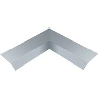

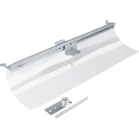
- Floor installation systems
- Basic manual
- Table of Contents
- FAQs 4
- Basic knowledge ....18
- FAQs
- questions - 7 answers
- Question 1: Which floor installation system is to be used?
- Question 2: How is the cable volume calculated?
- Question 3: How high is the planned floor structure?
- Question 4: Which floor covering will be laid?
- Question 5: How will the floor covering be cleaned?
- Question 6: What are the maximum loads that can occur?
- Question 7: Which supply and installation units are required?
- Answer 1: Which floor installation system is to be used?
- Screed-covered duct system
- Flush-screed duct systems
- On-floor duct system
- Raised floor system
- Cavity floor system
- Answer 2: How is the cable volume calculated?
- Answer 3: How high is the planned floor structure?
- Answer 4: Which floor covering will be laid?
- Answer 5: How will the floor covering be cleaned?
- Dry cleaned and "moist cleaned" floors
- Wet cleaned floors
- Answer 6: Which loads can occur?
- N Standard
- N drive-on
- Answer 7: Which installation units are required?
- Supply and installation units
- Polyamide supply unit
- Aluminium supply unit
- Stainless steel supply units
- Basic knowledge
- Important note
- Basic planning principles
- Requirements for installation technology
- Requirements from building conception
- Requirements for organisation
- Requirements for security
- Installation requirements / construction requirements
- Duct systems
- Screed-flush duct systems
- Raised floor installation system
- Cavity floor installation system
- Basic principles of screed
- Screed structure
- Screed work
- Screed types
- Flowing screed:
- Aggressive screed:
- Corrosion:
- :hager
- Floor structure
- Floor structure 50 mm
- Floor structure 75 mm
- Floor structure 105 mm
- Information on the floor covering and for the floor layer
- Information on the floor covering
- Information for the floor layer
- Preconditions for laying floor coverings
- Laying floor covers on BKB / BKG ducts
- Laying floor covers on BKF(D) / BKW(D) ducts
- Special features for cassettes with covering joint edge
- Determining the cable volume
- Bend radii
- Power supply and device installation units
- Supply units VQ/VE/VR
- Stainless steel cassette EKQ/EKR/EKSQ/EKSR
- Wet-cleaned supply units VANR
- UD floor box set UDKPQ
- Floor socket outlets BSR02
- Hinged cover for flat floor mounting KDQ/KDE
- IP degree of protection
- Dry cleaning
- Moist cleaning
- Wet cleaning
- IK degree of impact resistance
- Mechanical/thermal loads
- Loads and their impacts on installation systems
- Standardisation and testing
- Standardisation
- Classification of floor installation systems
- Testing
- Load testing of electrical installation duct systems
- Load capacity for screed-flush duct systems (BK) and their installation units
- Load capacity of screed-covered floor installation systems
- Erector specifications
- Protection against electric shock
- Mechanical load of cables
- Separation of different services
- Fire protection
- Equipotential bonding
- Inter-unit working
- Inter-unit working - Screed work
- General information for screed layers
- Inter-unit working - Floor covering work
- Inter-unit working - Building cleaning
- Sound protection and impact noise
- Impact noise reduction for floor installation systems
- Appendix
- Overview of floor installation systems - cable assignment
- Reference sources of standards and specifications
Brand : HAGER
Model : BKFDE300145
Category : Système d'installation électrique au sol