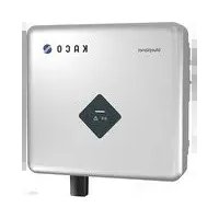
blueplanet 5.0 NX1 M2 - Battery charger Kaco - Free user manual and instructions
Find the device manual for free blueplanet 5.0 NX1 M2 Kaco in PDF.


| Product Type | Solar Inverter / Battery Charger |
| Model | blueplanet 5.0 NX1 M2 |
| Brand | Kaco |
| Maximum Input Power (DC) | 6000 W |
| Maximum Output Power (AC) | 5000 W |
| Number of MPP Trackers | 2 |
| Maximum Input Voltage | 1000 V |
| Operating Voltage Range | 200 V – 800 V |
| Maximum Input Current | 11 A per MPPT |
| AC Output Voltage | 230 V (single phase) |
| Grid Frequency | 50 Hz / 60 Hz |
| Maximum Efficiency | 97.5% |
| Protection Class | IP65 |
| Dimensions (H x W x D) | 580 x 430 x 200 mm |
| Weight | 22 kg |
| Cooling | Natural convection (fanless) |
| Operating Temperature Range | -25°C to +60°C |
| Display | Graphic LCD with touch buttons |
| Communication | RS485, Ethernet, WLAN (optional) |
| Warranty | 5 years (extendable) |
| Maintenance | Clean air vents periodically; check connections annually |
Frequently Asked Questions - blueplanet 5.0 NX1 M2 Kaco
User questions about blueplanet 5.0 NX1 M2 Kaco
0 question about this device. Answer the ones you know or ask your own.
Ask a new question about this device
Download the instructions for your Battery charger in PDF format for free! Find your manual blueplanet 5.0 NX1 M2 - Kaco and take your electronic device back in hand. On this page are published all the documents necessary for the use of your device. blueplanet 5.0 NX1 M2 by Kaco.
USER MANUAL blueplanet 5.0 NX1 M2 Kaco
KACO

new energy.
KACO blueplanet 3.0 NX1 M2
KACO blueplanet 3.7 NX1 M2
KACO blueplanet 4.0 NX1 M2
KACO blueplanet 5.0 NX1 M2
Manual
■ English translation of German original

Authorised electrician Important safety instructions

Android APP

iOS APP

Installation video 3.0-5.0 NX1

Start-up video via APP
Legal provisions
The information contained in this document is the property of KACO new energy GmbH. Publication, in whole or in part, requires the written permission of KACO new energy GmbH.
KACO warranty
You can download the current warranty conditions from the Downloads folder on our website at http://www.kaco-newenergy.com.
Definitions on product designations
In this manual, the product "Photovoltaic feed-in inverter" is referred to as the device for ease of reading.
Trademarks
All trademarks are recognised, even if not explicitly identified as such. A lack of identification does not mean that a product or designation/logo is free of trademarks.
Software
This device contains open source software developed by third parties and in some cases licensed under GPL and/or LGPL. More details on this topic and a list of the open source software used, as well as the corresponding licence texts, can be found on the associated "KACO NX Setup" APP in the "Info" menu under "Imprint", "Wi-Fi Stick Licences" and "Mobile APP Licences".
Photovoltaic feed-in inverter
Table of contents
1 General information.... 1
1.1 Notes regarding this document.... 1
1.2 More information.... 1
1.3 Layout of Instructions.... 1
1.4 Target group....2
1.5 Marking 3
2 Safety 4
2.1 Intended use 4
2.2 Protection features 5
3 Description of the device....6
3.1 Mode of operation 6
3.2 System layout....6
4 Technical data 7
4.1 Electrical data....7
4.2 General data....8
4.3 Environmental data....8
4.4 Accessories 8
5 Transportation and Delivery....9
5.1 Scope of delivery....9
5.2 Transporting the device 9
5.3 Installation tool 9
6 Assembly and preparation.... 10
6.1 Choosing the installation location.... 10
6.2 Unpacking the device 11
6.3 Fastening the mount 12
6.4 Installing and securing the device 13
7 Installation 14
7.1 General information.... 14
7.2 Surveying the connection area.... 14
7.3 Making the electrical connection....15
7.4 Connecting the device to the power grid..... 15
7.5 Connecting the PV generator to the device ..... 17
7.6 Creating equipotential bonding 20
7.7 Connecting the interfaces 20
7.8 Connecting the Smart-Meter for dynamic feed-in 21
8 Commissioning 23
8.1 Requirements 23
8.2 Preconditions relating to standards 23
9 Configuration and operation 24
9.1 Start condition....24
9.2 Initial start-up 24
9.3 Authorisation....25
9.4 Operating system and system configuration.... 26
9.5 Signal elements 27
9.6 Connecting to the device....28
9.7 Menu of the Communication unit....31
9.8 Additional functions 34
9.9 Menu of Inverter 37
9.10 Operation mode 38
9.11 Enabling functions.... 39
9.12 Performing a firmware update....49
9.13 Monitoring with "blueplanet web" 51
9.14 Monitoring the device....52
9.15 Active power control with a Smart-Meter ..... 52
9.16 Information on dynamic feed-in 52
10 Maintenance and troubleshooting 55
10.1 Visual inspection....55
10.2 Cleaning....55
10.3 Shutting down for maintenance work / troubleshooting....56
10.4 Troubleshooting....57
10.5 Error code....57
10.6 Fault during connection set-up and search..... 60
10.7 Disconnecting connections....61
11 Decommissioning and dismantling.... 62
11.1 Switching off the device 62
11.2 Uninstalling the device....62
11.3 Disassembling the device 63
11.4 Packaging the device 63
11.5 Storing the device....63
12 Disposal....63
13 Service and warranty.... 63
14 Appendix....64
14.1 EU Declaration of Conformity 64
1 General information
1.1 Notes regarding this document

WARNING
Improper handling of the device can be hazardous!
You must read and understand the manual in order to install and use the device safely.
Other applicable documents
During installation, observe all assembly and installation instructions for components and other parts of the system. These instructions also apply to the device, associated components and other parts of the system.
Some of the documents required for the registration and approval of your system are included with the manual.
Retention of documents
This manual and other document must be stored near the system and be available at all times.
• The current version of the manual can be downloaded from www.kaco-newenergy.com.
Original version
This document has been produced in several languages. The German version is the original version. All other language versions are translations of the original version.
1.2 More information
Links to more detailed information can be found at www.kaco-newenergy.com.
| Document title | Document type |
| Technical data sheet | Product flyer |
| Dynamic feed-in limitation and blueplanet web with/without data logger | Application Notes |
| Firmware package | Zip file |
| Software | Automatic update for iOS / Android app |
| EU Declaration of Conformity | Certificates |
| Country-specific certificates - Certification for specific subassemblies | Certificates |
1.3 Layout of Instructions
1.3.1 Symbols used

General hazard

Fire and risk of explosion

Electrical voltage

Risk of burns

Earthing - ground conductor
1.3.2 Safety warnings symbols guide

! DANGER
High risk
Failure to observe this warning will lead directly to serious injuries or even death.

WARNING
Potential risk
Failure to observe this warning may lead to serious injuries or even death.

CAUTION
Low-risk hazard
Failure to observe this warning will lead to minor or moderate injuries.
NOTE
Risk of property damage
Failure to observe this warning will lead to property damage.
1.3.3 Additional information symbols

NOTE
Useful information and notes
Information that is important for a specific topic or objective, but that is not safety-relevant.
1.3.4 Symbols for instructions
Prerequisite for use.
1 Perform next step
2 Additional action sequence
⇒ Interim result of the action
» End result
1.4 Target group
All activities described in the document may only be carried out by skilled personnel who have the following qualifications:
• Knowledge about how an inverter functions and operates.
• Training in the handling of hazards and risks during the installation and operation of electrical devices and systems.
• Education concerning the installation and start-up of electrical devices and systems.
• Knowledge of applicable standards and directives.
• Knowledge and adherence to this document with all safety notices.
1.5 Marking
You will find the name plate with the following data for service and other requirements specific to installation on the right side panel of the product:
- Product name
- Part number
- Serial number
- Date of manufacture
- Technical details
- Disposal information
– Certification marking, CE marking.
| KACO new energy Werner-von-Siemens-Allee 1 7.4172 Neckarsulm | blueplacket 5.0 NX1 M2 WM OD IIS0 | ||||
| Part number | 1002018 | ||||
| Serial number | 5.0NX1200001 | Year | Q1/21 | ||
| Input | Vmax PV / Isc PV(max) / Inom PV | 580 V/2x18 A/2x 12 A | |||
| V: MPP at Pnom / V- range | 220 V - 490 V / 80 V - 550 V | ||||
| Output | Nominal voltage | 220 V (1/N/PE) | |||
| 230 V (1/N/PE) | |||||
| 240 V (1/N/PE) | |||||
| Voltage range continuous operation | 180 Vac - 290 Vac | ||||
| Current(maximum continuous) | 22.7 A | ||||
| Frequency range | -45 Hz - 65 Hz | ||||
| Output Power | Snom at 230 V Unom | 5000 VA | |||
| Reactive power | 0 - 60% Snom | cos phi | 0.8 - 0.8 ind/cap | ||
| Environ- ment | Temperature range | -25°C, -60°C/-13°F, +140°F | |||
| Protection class / Ingress protection | I / IP65 | ||||
| No galvanic separation / Ungrounded Arrays Only | Max. Backfeed Current | 0 | |||
| Grid Support Interactive Inverter | ARC fault circuit protection | none | |||
| Interface protection according to country specific requirements, details see manual | |||||
Fig. 1.Name plate
2 Safety
! DANGER
Lethal voltages are still present in the connections and cables of the device even after the device has been switched off and disconnected!
Coming into contact with the lines and/or terminals/busbars in the device can cause serious injury or death.

Do not open the device.
The device must be mounted in a fixed position before being connected electrically.
Comply with all safety regulations and current technical connection specifications of the responsible power supply company.
The device is only permitted to be mounted, installed and commissioned by a qualified electrician.
Switch off the grid voltage by turning off the external circuit breakers.
Do not touch the cables and/or terminals/busbars when switching the device on and off.
Check that all AC and DC cables are completely free of current using a clip-on ammeter.
The electrician is responsible for observing all existing standards and regulations. The following points must be taken into account:
- Keep unauthorised persons away from the device and/or system.
- In particular, observe standard 1 "Requirements for special types of premises, rooms and installations - Solar photovoltaic (PV) power supply systems" in the respective regionally applicable version
- Ensure operational safety by providing proper grounding, conductor dimensioning and appropriate protection against short circuiting.
- Observe all safety instructions on the product and in these operating instructions
- Switch off all voltage sources and secure them against being inadvertently switched back on before performing visual inspections and maintenance.
• When taking measurements on the live device: - Do not touch the electrical connections
– Remove all jewellery from wrists and fingers
– Ensure that the testing equipment is in safe operating condition
• Modifications to the surroundings of the device must comply with the applicable national and local standards
2.1 Intended use
The device is a transformerless PV inverter which converts the direct current of the PV generator into grid-compatible single-phase alternating current and then feeds the single-phase alternating current into the public power grid.
The device is built using state-of-the-art technology and in accordance with the recognized safety rules. Nevertheless, improper use may cause lethal hazards for the operator or third parties, or may result in damage to the product and other property.
The device is intended for indoor and outdoor applications and may only be used in countries for which it has been approved or for which it has been released by KACO new energy and the grid operator.
Operate the device only with a permanent connection to the public power grid. The country and grid type selection must be commensurate with the respective location and grid type.
The requirements of the grid operator must be met for grid connection to take place. The permission of the relevant authorities may also be required in order to secure authorisation to connection to the grid.
The device may only be operated with PV arrays (PV modules and wiring) of protection class II pursuant to IEC 61730, application class A.
The enclosed documentation is an integral part of the product. The documentation must be read, observed and stored in a place which is freely accessible at all times.
| 1 | Country | Standard |
| EU | Harmonised document - HD 60364-7-712 (European implementation of the IEC standard) |
The name plate must be permanently attached to the product.
Any other or additional use of the device shall be regarded as improper. This includes:
• Use of a distribution system that is not described (grid type)
• Use of sources other than PV-strings
- Mobile use
• Use in rooms where there is a risk of explosion
• Use in direct sunlight, rain or a storm or other harsh environmental conditions
- Use in an outdoor area that does not meet the environmental conditions set down in Technical Data > Environmental Data.
• Operation outside the specification intended by the manufacturer
• Overvoltage on the DC connection of over 580 V
- Modifying the device
- Standalone mode
2.2 Protection features
The following monitoring and protection functions are built-in:
• System for monitoring the device temperature
• EMC filters to protect the inverter from high-frequency grid interference
• Anti-islanding detection according to the current standards.
• Isolation detection / residual current monitoring and disconnection function to detect isolation faults
3 Description of the device
3.1 Mode of operation
The device converts the DC voltage generated by the PV-modules into AC voltage and feeds this into the power grid. The starting procedure begins when there is sufficient sunlight and a specific minimum voltage is present in the device. The feed-in process begins once the PV generator has passed the insulation test and the grid parameters are within the requirements imposed by the grid operator for a specific monitoring time. If, as it gets dark, the voltage drops below the minimum voltage value, feed-in mode ends and the device switches off.
3.2 System layout
![graph TD A["PV generator"] --> B["Inverter"] C["PV generator"] --> D["Inverter"] B --> E["Line protection"] D --> F["Line protection"] E --> G["KWh/KWh Feed-in meter"] F --> G G --> H["Selective main switch"] H --> I["Grid monitoring point"] J["Reference counter"] --> K["Load"] K --> L["Selective ma…](/content/2026/06/1366546/images/a7d9b77cd55963b4de93b1ea58ecc4acc510cb23cea82856533ba2a9ffe05f86.jpg)
Fig. 2. Circuit diagram of a system with two inverters
| Key | Definition / information on the connection |
| PV generator | The PV generator converts the radiant energy of sunlight into electrical energy. |
| Inverter | The PV generator is connected to the device's DC connection. |
| Line protection | The circuit breaker is an overcurrent protection device. |
| Feed-in meter | The feed-in meter is to be specified and installed by the power supply company. Some power supply companies also allow the installation of your own calibrated counters. |
| Selective main switch | The selective main switch is to be specified by the power supply company. |
| Reference counter | The reference counter is to be specified and installed by the power supply company. This measures the amount of energy drawn. |
| Integrated DC isolator switch | Use the integrated DC isolator switch to disconnect the device from the PV generator. |
4 Technical data
4.1 Electrical data
| KACO blueplanet | 3.0 NX1 M2 | 3.7 NX1 M2 | 4.0 NX1 M2 5.0 NX1 M2 | |
| DC Input levels | ||||
| Recommended generator power range | 3.0 kW | 3.68 kW | 4.0 kW | 5.0 kW |
| MPP range at nominal power | 140-480 V | 165-480 V | 180-480 V | 220-480 V |
| Working range | 80-550 V | |||
| Rated voltage | 360 V | 360 V | 360 V | 360 V |
| Starting voltage | 80 V (PLC switch-on voltage, feed-in voltage is 100 V) | |||
| No-load voltage | 580 V | |||
| Max. input current 2 | 2*12 A | |||
| Number of strings | 2 | |||
| Number of MPP controls | 2 | |||
| Max. short-circuit current (Isc max.) | 2 x 18 A | |||
| Input source feedback current | 0 A | |||
| Polarity safeguard | yes | |||
| String fuse | no | |||
| DC overvoltage protection | no | |||
| KACO blueplanet | 3.0 NX1 M2 | 3.7 NX1 M2 | 4.0 NX1 M2 | 5.0 NX1 M2 |
| AC Output levels | ||||
| Nominal power | 3 kVA | 3.68 kVA | 4 kVA | 5 kVA |
| Rated voltage | 230 V [3/N/PE] | |||
| Voltage range: continuous operation | 180 V - 290 V | |||
| Rated current | 13 A | 16 A | 17.4 A | 21.7 A |
| Max. continuous current | 15 A | 16 A | 20 A | 22.7 A |
| Contribution to peak short-circuit current ip | 48 A | |||
| Initial short-circuit alternating current (Ik" first single period effective value) | 34 A | |||
| Make current | <20 % of the rated AC current for a maximum of 20 ms | |||
| Rated frequency | 50/60 Hz | |||
| Frequency range | 45 – 65 Hz | |||
| Reactive power | 0 - 60 % Snom | |||
| cos-phi | 0.8 inductive.... 0.8 capacitive | |||
| Number of feed-in phases | 1 | |||
| Distortion factor (THD) | <3% | |||
| Max. voltage range (up to 100 s) | 295 V | |||
| AC overvoltage protection | no | |||
2 The “Max. input current” is the maximal theoretical value for operation with full power when the feed-in power is low. The inverter switches to the maximum AC output power.
The "Max. short-circuit current ( ISCmax .)" together with the open circuit voltage ( UOCmax ) defines the characteristic of the connected PV generator. This is the relevant value for string design and represents the absolute maximum limit for inverter protection. The connected PV generator must be designed in such a way that the maximum short-circuit current is less than or equal to the ISCmax of the inverter under all foreseeable conditions. The design must in no case result in a short-circuit current greater than the ISCmax of the inverter.
4.2 General data
| KACO blueplanet | 3.0 NX1 M2 | 3.7 NX1 M2 | 4.0 NX1 M2 | 5.0 NX1 M2 |
| Max. efficiency | 97.5% | |||
| Europ. Efficiency | 96.02% | 96.33% | 96.47% | 96.70% |
| Self consumption: Standby | 5 W | |||
| Feed-in from | 60 W | |||
| Transformer unit | no | |||
| Protection class / over voltage category | I / III (AC) II (DC) | |||
| Grid monitoring | Country-specific | |||
| Distribution system | TN-C-System, TN-C-S-System, TN-S-System, TT-System | |||
| Display | LED | |||
| Controls | no | |||
| Menu languages | DE, EN | |||
| Interfaces | Communication unit /RS485 (e.g. smart meter) (optional) | |||
| Communication | WLAN | |||
| Radio technology | WLAN 802.11 b / g / n | |||
| Frequency spectrum | 2,412 MHz - 2,472 MHz | |||
| Antenna gain | 2 dBi | |||
| Potential-free relay | no | |||
| DC isolator switch | yes | |||
| AC isolator switch | no | |||
| Cooling | natural | |||
| Number of fans | no | |||
| Noise emission | < 25 dB(A) | |||
| Housing material | Aluminium | |||
| HxWxD | 355 mm * 376 mm * 145 mm | |||
| Weight | 11 kg | |||
| Certifications | Overview: see website / download area | |||
4.3 Environmental data
| KACO blueplanet | 3.0 NX1 M2 | 3.7 NX1 M2 | 4.0 NX1 M2 | 5.0 NX1 M2 |
| Installation height | 3,000 m | |||
| Installation distance from coast | 3,000 m | |||
| Ambient temperature | -25 °C ...+60 °C | |||
| Power derating from | +40 °C | |||
| Protection rating (KACO installation location) | IP65 | |||
| Humidity range (non-condensing) [%] | 100% | |||
4.4 Accessories
| Accessory articles KACO order no. | |
| NX1 smart meter connection kit | 3015112 |
| Eastron SDM230 | 3015113 |
5 Transportation and Delivery
Every product leaves our factory in perfect electrical and mechanical condition. Special packaging ensures that the devices are transported safely. The shipping company is responsible for any transport damage that occurs.
5.1 Scope of delivery
| Article | Description | Quantity |
| A | Inverter | 1 piece |
| B | Wall mounting bracket | 1 piece |
| C | Mounting accessory kit: Wall fixings and hex bolts (3×) M4×10 mm screw (4×) | 1 set |
| D | DC plug connector | 2 pairs |
| E | AC connector | 1 piece |
| F | Communication device (WiFi stick) | 1 piece |
| G | Documentation | 1 set |


Check the equipment included
- Inspect the device thoroughly.
- Immediately notify the shipping company in case of the following:
o Damage to the packaging that indicates that the device may have been damaged.
- Obvious damage to the device.
- Send a damage report to the shipping company immediately.
- The damage report must be received by the shipping company in writing within six days following receipt of the device. We will be glad to help you if necessary.
5.2 Transporting the device

CAUTION
Hazard due to impact; risk of breakage to the device!
Pack the device securely for transport.
Transport the device using the intended carrying handles of the packaging box.
Do not expose the device to any shocks.
5.3 Installation tool
The codes given in the table below are used in all usage instructions for assembly/installation/maintenance and disassembly for the tools and tightening torques being used.
| Code (s) | Shape of the connector |
| × W | External hexagon |
| × T | Torx |
| × S | Slot |
| × P | Phillips |

Fig. 3.Form pattern
6 Assembly and preparation
6.1 Choosing the installation location

! DANGER
Risk of fatal injury due to fire or explosions!
Fire caused by flammable or explosive materials in the vicinity of the device can lead to serious injuries. Do not mount the inverter in an area at risk of explosion or in the vicinity of highly flammable materials
CAUTION

Property damage due to gases that have an abrasive effect on surfaces when they come into contact with ambient humidity caused by weather conditions.
The device housing can be seriously damaged due to gases in combination with air humidity resulting from weather conditions (e.g. ammonia, sulphur).
If the device is exposed to gases, the installation must be carried out at observable locations.
Perform regular visual inspections.
Immediately remove any moisture from the housing.
- Ensure adequate ventilation at the installation location.
Immediately remove dirt, especially on vents.
Failure to follow these warnings may result in damage to the device that is not covered by the manufacturer's warranty.

NOTE
Access by maintenance personnel for service
Any additional costs arising from unfavourable structural or installation conditions will be billed to the customer.
Installation space
- As dry as possible, climate-controlled. The waste heat must be dissipated away from the device
- U nobstructed air circulation
- W hen installing the device in a control cabinet, provide forced ventilation for sufficient heat dissipation
- C lose to the ground, accessible from the front and sides without requiring additional resources
- n outdoor areas, protected on all sides from direct weather exposure and sunlight (thermal heating). Implementation where necessary via constructional measures, e.g. wind breaks
- M make sure that the inverter is installed out of the reach of children.
- T o ensure an optimal operation and a long service life, the temperature of the installation environment of the inverter should be ≤40 °C.
Installation surface
- M ust have adequate load-bearing capacity
- M ust be accessible for installation and maintenance
- Must be made of heat-resistant material (up to 90 °C)
- M ust be flame resistant
- M inimum clearances to be observed during installation [see Fig. 9 on Page 12]

Fig. 4.Device for outdoor installation
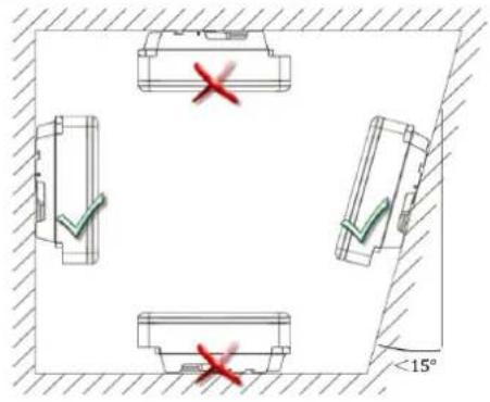
Fig. 5. Permissible installation location
6.2 Unpacking the device

CAUTION
Risk of injury due to excessive physical strain
Lifting the device, for transport, relocation and assembly can result in injuries (e.g. back injuries).
Only lift the device using the grip recesses provided.
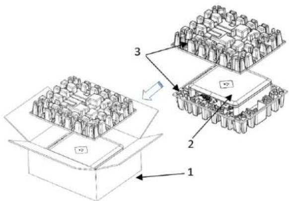
Fig. 6. Unpacking the device

Fig. 7.Lift the unit
Key
1 Packaging box 3 Protective packaging
2 Device 4 Grip recesses
The device has been transported to the installation site.
- Loosen packaging tape from cardboard box.
- Open carton at the front.
- Remove installation material and documentation.
- Pull up top protective packaging to remove.
- Remove device from the packaging.
- Place the protective packaging back into the packaging box.
- Lift the device at the intended positions.
» Continue installing the mount.
6.3 Fastening the mount

CAUTION
Hazard when using unsuitable fixing materials!
If unsuitable fixing materials are used, the device could fall and persons in front of the device may be seriously injured.
Use only fixing materials that are suitable for the mounting base. The fastening materials supplied are only suitable for masonry and concrete.
Only install the device in an upright position.
NOTE

Power reduction due to heat accumulation!
If the recommended minimum clearances are not observed, the device may go into power regulation mode due to insufficient ventilation and the resulting heat build-up.
Observe minimum clearances and provide for sufficient heat dissipation.
All objects on the device housing must be removed during operation.
Ensure that no foreign bodies prevent heat dissipation following device installation.


Fig. 8. Drill holes for wall mounting
Fig. 9. Mounting the wall bracket
Key
| 1 Drill three holes [ 10 mm depth 70 mm] | 5 Screw for securing purposes |
| 2 Insert screws and anchors | A Minimum clearance: 300 mm |
| 3 Take out the wall bracket | B Minimum clearance: 500 mm |
| 4 Install the wall holder | C Minimum clearance: 500 mm |
Cardboard packaging with mount and mounting kit removed from the packaging and opened.
1. Mark the mounting position on the wall surface according to the position of the mount plate by drawing three marks.
2. Mark the positions of the drill holes and drill three holes.
NOTE: The minimum clearances between two devices, or the device and the ceiling or floor have already been taken into account in the diagram.
3. Fix the mount to the wall using suitable mounting fixtures from the mounting kit [×W-10].
NOTE: Make sure that the mount is oriented correctly.
» Proceed with the installation of the device.
6.4 Installing and securing the device
CAUTION

Risk of injury from improper lifting and transport.
If the device is lifted improperly, it can tilt and result in a fall.
Always lift the device vertically using the openings provided.
Use a climbing aid for the chosen installation height.
Wear protective gloves and safety shoes when lifting and lowering the device.
Lifting and installing the device
The mount has been installed.
- Lift the device using the recesses. Observe the centre of gravity!
- Fit the device onto the mounting bracket. Check both sides of the heat sink to ensure that it is securely in place.
- Insert the screw provided into the lug of the mount and secure the device to prevent it from being lifted off. [×P / 2 Nm]
NOTE: At this point, the screw described above can be replaced by a special screw as anti-theft protection.
» Device is installed. Proceed with the electrical installation.

Fig. 10. Mount the inverter to the wall bracket

Fig. 11. Check the device is secure

Fig. 12. Secure the inverter

CAUTION
Property damage as a result of condensation

During pre-assembly of the device, moisture can enter the internal space via the DC connectors and the dust-proof screw connections. The resulting condensate can cause damage to the device during installation and start-up.
- K keep the device closed during pre-assembly and do not open the connection area until you perform installation.
- S eal off any plug-in connections and screw fittings using sealing covers.
- I immediately remove any moisture from the housing.
7 Installation
7.1 General information

DANGER
Lethal voltages are still present in the connections and cables of the device even after the device has been switched off and disconnected!

Coming into contact with the lines and/or terminals/busbars in the device can cause serious injury or death.
Do not open the device.
The device must be mounted in a fixed position before being connected electrically.
Comply with all safety regulations and current technical connection specifications of the responsible power supply company.
Switch off the grid voltage by turning off the external circuit breakers.
Check that all AC and DC cables are completely free of current using a clip-on ammeter.
Do not touch the cables and/or terminals/busbars when switching the device on and off.
7.2 Surveying the connection area
The connection for the AC supply is located on the housing in the lower right area. The DC input source is connected to the DC plugs and DC sockets on the base plate.
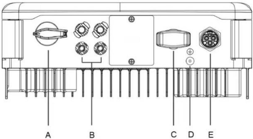
Fig. 13. Surveying the connection area
| A DC integrated isolator switch | D | Housing grounding |
| B DC connector for PV generator | E | AC connection socket |
| C Connection for Communication unit | ||
7.3 Making the electrical connection

NOTE
Select conductor cross-section, safety type and safety value in accordance with the following basic conditions:
Country-specific installation standards; power rating of the device; cable length; type of cable installation; local temperature
7.3.1 Requirement for supply lines and fuse
| DC-side | |
| Max. outer diameter | 5 – 8 mm |
| Max. cable cross-section (with wire sleeves) | 2.5 - 6 mm2 (DC plug connector) |
| Recommended cable type Solar cable | |
| AC-side | |
| Max. conductor cross-section | 4 - 6.0 mm2 |
| Max. outer diameter (with wire sleeves) | 10 - 16 mm |
| Length of insulation to be stripped off | 13 mm |
| Type of connection | Vaconn AC connector |
| Fuse protection for installation provided by customer | Max 25 A at 6 mm2 |
| Tightening torque | 1.4 Nm |
| Communication | |
| Recommended RS485 bus cable | LiYCYv (twisted pair) black for laying cable outside and in the ground, 2 x 0.5 mm2 |
| LiYCY (twisted pair) grey for dry and damp indoor spaces, 2 x 0.5 mm2 | |
7.4 Connecting the device to the power grid
7.4.1 Configuring the AC connection plug
You have completed assembly.
- Slide the cable fitting over the cable.
- Select seal according to cable diameter used.
- Slide the housing and seal over the cable.
- Remove the insulation from the cable. [sl. 53 mm]
- Shorten the wires N, L by 2 mm more than the PE conductor.
- Strip the wires N, L, PE by 13 mm.
- Flexible wires must be fitted with wire sleeves in accordance with DIN 46228.
- Insert wires into the contacts in accordance with the markings on the contact carrier.
- Tighten screws on contact carrier. [XT_8 / 2.0 Nm]
- Press contact carriers into the housing with an audible "click".
- Fix the housing and tighten the cable screw fitting. [W_29 / 3.5 Nm]
» Make the electrical connections.

Fig. 14.AC connection plug
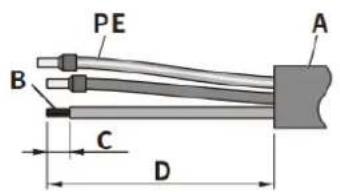
Fig. 15. Connect wires
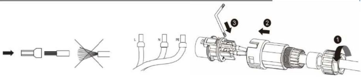
Fig. 16. Crimp wire sleeve to the contact
Fig. 17. Tighten the cable screw fitting
Key
| 1 | Cable fitting | A | External diameter ( φ 10 to 16 mm) |
| 2 | Seal | B | Conductor cross-section ( 4 to 6 mm 2 ) |
| 3 | Housing | C | Stripping length of the insulated cables (approx. 13 mm) |
| 4 | Contact carrier | D | Stripping length of the outer sheath of AC cable (approx. 53 mm) |
7.4.2 Make AC connection
AC connection plug configured correctly.
- Insert the AC connection plug into the device connector on the device.
NOTE: The AC connection is secure when an audible click is heard.
- Lay the cables correctly and in accordance with the following rules:
- Lay the cables around the device with a minimum clearance of 20 cm
- Never lay cables over semiconductors (cooling bodies).
- Excessive bending force may negatively impact the protection rating. Lay the cables with a bending radius of at least 4 times the cable diameter.
» The device is connected to the power grid.

Fig. 18. Engage the AC connector with the device connector

NOTE
An AC-side disconnection unit must be provided during the final installation stage. This disconnector mechanism must be installed so that it can be accessed at any time without obstruction.

NOTE
If a residual current circuit breaker is necessary due to the installation specification, a type A residual current circuit breaker must be used.
For questions regarding the appropriate type, please contact the installer or our KACO new energy customer service.

NOTE
When the line resistance is high, i.e. long cables on the grid side, the voltage at the grid terminals of the device will increase in feed-in mode. If the voltage exceeds the country-specific grid overvoltage limit value, the device switches off.
Ensure that the cable cross-sections are sufficiently large or that the cable lengths are sufficiently short.
7.5 Connecting the PV generator to the device
7.5.1 Configuring the DC connector
! DANGER
Risk of fatal injury due to electric shock!

Coming into contact with live connections can cause serious injury or death. When there is sunlight present on the PV generator, there is DC voltage on the open ends of the DC cables.
Make sure that PV modules have good insulation against ground.
On the coldest day based on statistical records, the max. open-circuit voltage of the PV modules must not exceed the max. input voltage of the inverter.
Check the polarity of DC cables.
Ensure that the device is completely free of DC voltage.
Do not disconnect DC connectors under load.


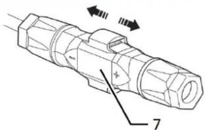
Fig. 19. Insert wires
Fig. 20.Slide insert into sleeve
Fig. 21. Check fastening
| Legend | |||
| 1 | Wire for DC connection | 5 | Cable fitting |
| 2 | Spring | 6 | Contact plug |
| 3 | Insert | 7 | Coupling |
| 4 | Sleeve | ||
Connection area opened.
NOTE: Before proceeding with the isolation ensure that you do not cut any individual wires.
- Insert isolated wires with twisted ends carefully up to the connection.
NOTE: Wire ends must be visible in the spring.
-
Close the spring in such a way that the spring latches.
-
Slide insert into sleeve.
-
Secure and tighten the cable fitting [W_15/1.8 Nm].
-
Join insert with contact plug.
-
Check latch by lightly pulling on the coupling.
» Make the electrical connections

NOTE
The permissible bending radius of at least 4x the cable diameter should be observed during installation. Excessive bending force may negatively impact the protection rating.
All mechanical loads must be absorbed in front of the plug connection.
Rigid adaptations are not permitted on DC plug connectors.
7.5.2 Checking the PV generator for a ground fault
! DANGER

Risk of fatal injury due to electric shock!
Coming into contact with live connections can cause serious injury or death. When there is sunlight present on the PV generator, there is DC voltage on the open ends of the DC cables.
Only touch the PV generator cables on the insulation. Do not touch the exposed ends of the cables.
Avoid short circuits.
Do not connect any strings with a ground fault to the device.

NOTE
The threshold value from which the insulation monitor reports an error can be set in the "Parameters" menu.
Ensure that there is no ground fault
1 Measure the DC voltage between the protective earth (PE) and the positive cable of the PV generator.
2 Measure the DC voltage between the protective earth (PE) and the negative cable of the PV generator.
⇒ If stable voltages can be measured, there is a ground fault in the DC generator or its wiring. The ratio between the measured voltages gives an indication as to the location of this error.
3 Rectify any errors before taking further measurements.
4 Measure the electrical resistance between the protective earth (PE) and the positive cable of the PV generator.
5 Measure the electrical resistance between the protective earth (PE) and the negative cable of the PV generator.
In addition, ensure that the PV generator has a total insulation of more than 2.0 MOhm, since the device will not feed in if the insulation resistance is too low.
6 Rectify any errors before connecting the DC generator.
7.5.3 Recommended standard connection
![graph TD A["Component A"] -->|DC+| B["Component B"] A -->|DC-| C["Component C"] B --> D["Output n1"] B --> E["Output n2"] C --> F["Output n1"] C --> G["Output n2"] style A fill:#f9f,stroke:#333 style B fill:#f9f,stroke:#333 style C fill:#ccf,stroke:#333 style D fill:#cfc,stroke:#333 style E fill:#cf…](/content/2026/06/1366546/images/cdfed3a59bbb985d755a199aae3b7e680573cec9521eaf6849ee9150c63e6760.jpg)
Possible connection
Two PV generators for each MPP tracker
The MPP voltages of the two DC strings can be different. They are supplied by separate, independently operating MPP trackers (MPP trackers A and B).
Number of modules per string:
Pmax per string < 0.6 * max. recommended PV generator power
MPP tracker A+B together < max. recommended PV generator power
Imax: Depending on PV generator
The input current per MPP tracker must not be exceed 12 A
Fig. 22. Recommended connection for blueplanet 5.0 NX1
7.5.4 Designing the PV generator

CAUTION
Damage to components due to faulty configuration!
In the expected temperature range of the PV generator the values for the no-load-voltage and the short circuit current must never exceed the values for Udcmax and Iscmax in accordance with the technical data.
Observe limit values in accordance with the technical data.

NOTE
Type and configuration of the PV modules
Connected PV modules must be dimensioned for the DC system voltage in accordance with IEC 61730 Class A, but at least for the value of the AC grid voltage.

NOTE
Dimensioning the PV generator
The device is designed with a reserve of DC short-circuit current resistance. This allows for oversizing of the connected PV generator. The absolute limit for the PV generator is the value of the max. short-circuit current (Isc max) and the max. no-load voltage (Uoc max).
7.5.5 PV generator
DANGER

Risk of fatal injury due to electric shock!
Coming into contact with live connections can cause serious injury or death. When there is sunlight present on the PV generator, there is DC voltage on the open ends of the DC cables.
Only touch the PV generator cables on the insulation. Do not touch the exposed ends of the cables.
Avoid short circuits.
Do not connect any strings with a ground fault to the device.

CAUTION
Damage to the PV generator in case of faulty configuration of the DC connector
Incorrect configuration of the DC connector (polarity +/-) leads to device damage in the DC connection if it is connected permanently.
Please check polarity (+/-) of the DC connector before connecting the PV generator.
Before using the solar modules, check the vendor's calculated voltage values against those actually measured. The DC voltage of the PV system must not exceed the maximum no-load voltage at any time.
Connecting the PV generator
The DC plug connector has to be configured and PV generator checked to ensure there is no ground fault.
1 Remove protective caps from the required DC connection plugs on the underside of the device.
2 Connect the DC plug connectors to the DC positive and DC negative connectors in pairs.
» The device is connected to the PV generator.
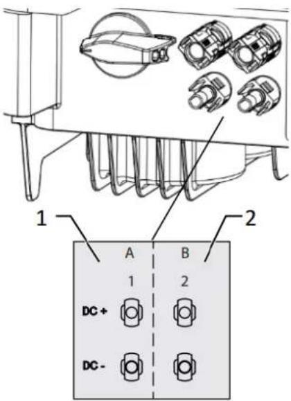
Fig. 23. Connection for DC+ and DC-
Closing the unused DC connectors
All existing strings are connected to the device.
NOTE: Meet the requirements of protection class IP65 by closing the unused plug connectors with the enclosed protective caps.
1 Press down the clamping bracket and push the forcing nut up to the thread. Insert the sealing plug into the DC plug connector and tighten the forcing nut.
2 Finally, insert DC plug connectors with sealing plugs into the corresponding DC input terminals on the device.
» Unused DC plug connectors are closed.

Fig. 24. Insert DC plug connectors and close unused connectors
7.6 Creating equipotential bonding

NOTE
Depending on the local installation specifications, it may be necessary to earth the device with a second ground connection. To this end, the threaded bolt on the underside of the device can be used.
The device has been installed on the mount.
1 Insert the grounding conductor into the suitable terminal lug and crimp the contact.
2 Align the terminal lug with the grounding conductor on the screw.
3 Tighten the screw tightly into the housing [× P_2/ 1.6 Nm].
» The housing is included in the equipotential bonding.
| Legend | |||
| 1 | M4 terminal lug | 3 | M4 screw |
| 2 | Earthing ground conductor | ||
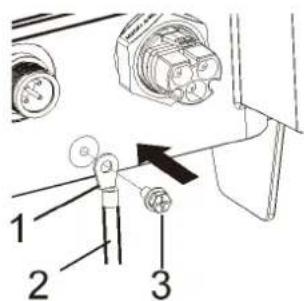
Fig. 25. Connect the grounding
7.7 Connecting the interfaces
7.7.1 Connection for Communication unit

NOTE
Damage to the inverter from electrostatic discharge
Components inside the inverter can be damaged beyond repair by electrostatic discharge.
Earth yourself before touching the components.

NOTE
Damage to the Communication unit due to rotation of the stick housing
When the Communication unit is attached to the inverter, the nut on the stick must be turned. The Communication unit can be damaged if you rotate the housing of the stick.
Do not rotate the actual Communication unit when attaching it to the device.
The device has been installed on the mount.
1 Remove the cap on the COM connector.
2 Insert the Communication unit into the existing connection and screw it tightly into the connection using the nut on the module.
NOTE: Do not rotate the actual Communication unit when attaching it to the device.
3 Ensure that the Communication unit is securely connected and the label on the module can be seen.
» The Communication unit is connected to the device.

Fig. 26. Remove the cap

Fig. 27. Connect the Communication unit
7.8 Connecting the Smart-Meter for dynamic feed-in
If you want to implement the function dynamically, you need to install the Smart Meter. The Communication unit is compatible with the Eastron Smart-Meter (SDM230 – Article no. 2015113) and is available via our customer service.

NOTE
The Smart-Meter must support the MODBUS protocol and communicates with baud rate 9600, parity "None", Stop-Bits "1"
Ensure that individual wires at the terminal contact of the Smart-Meter are attached with the correct torque and cannot work loose. Attach protective cover if fitted.

NOTE
Damage to the inverter from electrostatic discharge
Components inside the device can be damaged beyond repair by electrostatic discharge.
Ground yourself before touching a component.

NOTE
A network cable of category 5E or higher is required for connection to the RJ45 socket. A network cable with good resistance to UV radiation is also required for use outdoors.
The RS485 connection can support communication with a maximum installation length (across all inverters) of 1000 m. The individual and control connected must be measured in accordance with EMC requirements EN 62920 if the length of the cable attached at the signal and control connection is more than 30 m according to the standard.
The device and the Smart-Meter have been firmly installed on a mounting bracket.
- Fit suitable wire sleeves in accordance with DIN 46228-4 to the wires of the required cable and crimp [wire cross-section 0.5 - 0.6 mm 4 ]

Fig. 28. Configuring the cable
- Remove the protective cover from the housing base. (See Fig. 29)
- Release the forcing nut (Pos. 1) of the cable fitting at the terminal (See Fig. 30).
- Remove closing plug (Pos. 2) for required communication line, route the line through the forcing nut, the sealing sleeve and terminal, and guide the communication line with three turns through the magnetic ring (Pos. 3).
- Connect wires of the cable to terminal (Pos 4) as assigned (A/B). [Screwdriver type: PH2, tightening torque: 1.6Nm]
- Ensure that the cable is firmly attached.


Fig. 29. Removing protective cover
Fig. 30. Routing line through terminal
- Insert configured terminal into the socket provided. Mount terminal on device using screws of protective cover [screwdriver type: PH2, tightening torque: 1.6 Nm] and tighten forcing nut [tightening torque 3.0-3.5 Nm].


Fig. 31. Inserting terminal into the socket
- Fit wire sleeve to the other end of the cable and connect to the contacts of the Smart-Meter. Screwdriver type: PHO, tightening torque: 0.7 Nm See Fig. 32

Fig. 32.Connection to SDM 230

NOTE
Accessories package: NX1 smart meter connection kit (Art. 3015112)
The kit (terminal with seal, clamp, magnetic ring) is available via our customer service.
https://kaco-newenergy.com/service/customer-service/
8 Commissioning
8.1 Requirements

DANGER
Lethal voltages are still present in the connections and cables of the device even after the device has been switched off and disconnected!
Coming into contact with the lines and/or terminals/busbars in the device can cause serious injury or death.
The device is only permitted to be commissioned by a qualified professional.
Unauthorised persons must be kept away from the device.
The device has been mounted and electrically installed.
The PV generator supplies a voltage above the configured start voltage.
1 Connect the grid voltage using the external circuit breakers.
2 Connect the PV generator using the DC isolator switch (0 > 1)
» The device begins operation.

NOTE
For initial start-up of the device, the enclosed WiFi stick must be plugged into the connection port. A mobile terminal device with a WIFI interface is required for monitoring and setting parameters. No serial number dependent password is required here.
The following functions are only available via the associated app:
- Initial start-up.
- Setting parameters
- Special parameters (e.g. P(f), P(U), Q(U))
- Reset to Factory defaults.
8.2 Preconditions relating to standards
Attachment of safety label in accordance with UTE C15-712-1
The code of practice UTE C15-712-1 requires that, upon connection to the French low-voltage distribution network, a safety sticker showing a warning to isolate both power sources when working on the device must be attached to each device
- Attach the safety sticker provided to the outside of the device housing where it is clearly visible.

9 Configuration and operation
9.1 Start condition
The Communication unit is connected to the device and firmly screwed in place.
The device is connected on the AC and DC sides and supplied with sufficient DC voltage.
Note: Note the status of the LED during initialization, during operation and in the event of fault messages. This can provide you with accurate information about the current operating status of the device.
1 Check on the Communication unit that the blue LED lights up during the initialization process. If not, check the fastening again. Otherwise, replace the Communication unit.
2 Check on the device that the white LED lights up in feed mode. If not, there is a fault in the device.
Note: In case of faults, refer to the error code in Chapter 10.5
» Continue to set up the device monitor.
9.2 Initial start-up
Initial start-up of the inverter is carried out via a hotspot WLAN connection between the Communication unit (WIFI stick) connected to the inverter and a mobile terminal unit with installed "KACO NX Setup" APP.
There are two ways to connect with the hotspot created by this unit:
- Establish a simplified connection with the Communication unit by opening the APP and reading in the QR code on the Communication unit with Setup Mode. After scanning the QR code, you will be shown a WLAN network with the name B.... When selecting this WLAN network, it is not necessary to enter a password. Your mobile device will connect to the device automatically.
- Connect by opening the WLAN settings on the mobile terminal device and selecting the WLAN connection with the designation B.... and entering the password (registration code).
Note: The name SSID (serial number of the WiFi stick B...) and password (registration code) of the Communication unit can be found printed on the WiFi stick.
- You are successfully connected to the communication unit.
Step 2: Configuring the communication unit and inverter
We recommend the following steps for the initial start-up:
- Configuration communication unit
- Set up time zone. See Chapter 9.7.1 on page 31
- Configure network parameters See Chapter 9.7.3 below on Page on page 33 (Communication Unit Properties)
- Setting the monitoring and control functions See Chapter 9.7.4 below on page 34 (Monitoring & Control)
- Configuration Inverter
- Select country and grid standard See Chapter 9.9.3 below on page 38.
- Set local grid requirement (observe local grid requirements! E.g. cos-phi, P(f), Q(U)....) See Chapter 9.11 below on page 39
- View the instantaneous values of the inverter in order to detect any faults. See chapter 9.9.1 below on page 37.

NOTE
For further settings such as power control, zero-feed in or communication with a data logger, please refer to chapter 9.11 below
9.3 Authorisation

NOTE
In order to use the full range of functions of the "KACO NX SETUP" app, you should accept all requested authorisations. The app does not use these authorisations to record the user's telephone data. The current description reflects the firmware version 1.0.15. With newer firmware versions the following subchapters will be updated in time to inform you about current functions.

NOTE
If your device has a software version of V08 or higher, you will have many additional functions. However, you can update your V06/V07 version with ≥ V08 available on our website as described in the chapter 9.14.

NOTE
Our KACO website offers a wide range of further product information to assist you during start-up. You can find this information in the download area under: https://kaco-newenergy.com/de/downloads/. Follow the QR code link on the cover sheet to view the installation and start-up video.

NOTE
No password is required for initial start-up. A password must be entered again if it becomes necessary to change the parameters of the device after initial start-up. The specific password for the inverter can be requested from KACO Service. https://kaco-newenergy.com/de/service/kundendienst/

NOTE
Frequency band: Before configuring the network, please prepare a WLAN router that supports the 2.4G frequency band. The Communication unit can only be operated in the 2.4G frequency band. Installation location For a stable connection, the Communication unit or inverter should be no more than 10 m away from the router. Availability of SSID and password of the router The Communication unit supports only 32 characters for the SSID or password.

NOTE
We recommend integrating the Communication unit into your/your customer's WLAN network, if the signal quality of the network is insufficient or non-existent, then you will need to continue with hot-spot connection. To use monitoring and control functions (Monitoring Portal "blueplanet web"), there must be a connection to the internet via the customer's WLAN network.
9.4 Operating system and system configuration
The corresponding, free APP KACO NX Setup from the relevant APP store can be installed on a mobile terminal unit (smartphone or tablet PC) with an Android operating system, version 9.0 or newer or IOS operating system version 11.0 or newer. You will find QR code links on the cover sheet.
Below you will find illustrations of the connection options for initial start-up of the device and its optional integration into a local network.
If you integrate the device into a local network, it is possible to connect the device to a web portal or a client (data logger, system controller).
Option 1: Set-up via hotspot (with APP connection to the inverter with Communication unit)
![graph TD A["PV module"] --> B["Hotspot inverter"] B --> C["KACO NX Setup"] B --> D["Downloaded on the App Store"] B --> E["GET ON Google Play"] B --> F["Grid"] G["Inverter with communication device"] --> H["Consumption"] I["AC 1ph/N/PE"] --> H J["AC 3ph/N/PE"] --> H](/content/2026/06/1366546/images/e5c2d20722551d9e2031983be3f0a5b13605e054d9258a59294598d87e870ff7.jpg)
Fig. 33. Set up Communication unit via mobile end device – hotspot
Option 2: Set-up via local network
![graph TD A["blueplanet web"] --> B["Cloud"] B --> C["Internet"] C --> D["Router"] D --> E["PV module"] E --> F["Inverter with communication device"] F --> G["AC 1ph/N/PE"] F --> H["AC 3ph/N/PE"] H --> I["Grid"] J["KACO NX Setup"] --> K["GETT ON Google Play"] K --> L["Download on the App Store"] M["W…](/content/2026/06/1366546/images/540143870022049123dcfc477320bb05f8298acc43d5c7769c9029aba51341d0.jpg)
Fig. 34. Set up Communication unit via local network – WiFi2.4G
9.5 Signal elements
There are status LEDs on the Communication unit and on the inverter housing that indicate the operating status. The LEDs can display the following states:
| LED illuminated | LED flashing | LED flashes rapidly |
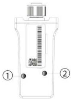
Fig. 35.LEDs on Communication unit
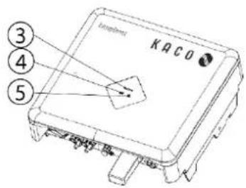
Fig. 36.LEDs on device
| Item | Operating status on Communication unit | LED | Description |
| 1 | Network communication |  | Note: For AP network configuration, you must be connected to the device's local WLAN network to re-enter the router information. The password for the local WLAN network is the registration key found on the name plate (See Abb. 50 on Communication unit).The blue "Network" LED flashes when the Communication unit is connected to the WLAN network. |
 | The blue "Network" LED is illuminated when the inverter is connected to the web portal.If the LED does not light up, check if the network SSID and password are correct and if the WLAN signal is strong enough. | ||
| 2 | Device communication | The green "Operating" LED is illuminated when the Communication unit establishes communication with the device. If it does not light up, there is a hardware defect. Contact our service team. | |
 | The green "Operating" LED flashes if the connection fails due to invalid router information. Use the "KACO NX Setup" APP to perform the network configuration. | ||
 | The green "Operating" LED flashes rapidly when the Communication unit is in network configuration mode. This disables the device's data capture function. | ||
| Item | Operating status on the device | LED | Description |
| 3 | Standby self-test | The white "Operating" LED flashes when AC and DC voltage is present.The device performs a self-test.After flashing, the device is ready for feed-in. | |
| 3 | Feed-in operation | The white "Operating" LED is illuminated when the device is feeding into the grid. The LED goes off when there is a malfunction. | |
| 3 | Feed-in mode with power reduction | Note: Dynamic power is also indicated by means of the LED. The white "Operating" LED flashes quickly if there is a power reduction of 45%-90%. If the power falls below 45%, the LED flashes slowly. | |
| 4 | COM | The white "Communication" LED is illuminated during communication with other devices (data logger, Smart-Meter, Communication unit) and during a firmware update via RS485. The LED is not illuminated if the communication is interrupted or non-existent. | |
| 5 | Fault | The red "Fault" LED lights up due to an error and the feed into the grid is interrupted. The corresponding error code is displayed in the KACO NX Setup APP in the Live values menu 9.9.1 on Page 37. If there is no fault, the LED goes out. |
1-5 Offline

No LED is lit.
There is no AC/DC supply to the device.
9.6 Connecting to the device
9.6.1 Connecting to the device for the first time
WLAN of your mobile device is enabled, and any existing customer WLAN network router is switched on.
Note: The initial connection is generally made via a hotspot.
The "KACO NX Setup" APP from the Android/iOS Store has been installed and opened on your mobile end device.
The Communication unit is connected to the COM port of the device. (See Chapter 7.7 on page 20)
Note: Each device in the device series must be configured with the enclosed Communication unit. Thereafter there is a fixed assignment to the device.
The access details for your / your customer's WLAN network are to be made available to the solar installer.
- Select
. - Grant authorisation for use of images, videos and camera.
- Scan the QR code on the Communication unit. Max. distance from the scan frame shown in the scan window. (See Fig. 40)
» The connection to the hotspot WLAN is established (B...).


Fig. 37.Select
Fig. 38. Scan QR code on Communication unit
new energy
Note: The connection is established exclusively via the hotspot until step 6. This is how long your mobile end device must be kept near the Communication unit.
- Confirm the WLAN network of the Communication unit by tapping the B... number displayed.
Note: After a short time you will have 2 options in
- Select the customer's WLAN network. The customer needs to enter the password and press the
button.
Note: If the connection fails, the Communication unit is not in range of the customer's router. You can improve the signal quality between the Communication unit and the router by interposing a repeater. However, this must also be connected to the same network.

Fig. 39. Access to the Communication unit with a mobile end device
Fig. 40.Enter the access data for the customer's WLAN network
Note: If the connection is successful, your communication unit will be connected to the customer's WLAN network. Your mobile end device now also needs to be connected to the customer's WLAN network.
- In
on the mobile end device, you now need to establish a connection with the customer's WLAN network.
Note: The password is pre-filled if a connection already exists.
- Note the checklist and status. Process takes up to 5 minutes.
» Your communication unit and your mobile end device are now on the same customer WLAN network. A successful connection is displayed in a new window.
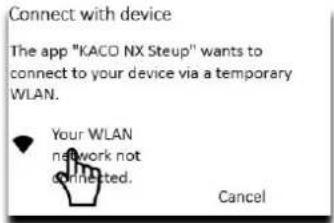
Fig. 41. Connect the inverter to the customer's WLAN

Fig. 42. Connect the mobile end device to the customer's WLAN

Fig. 43. The connection to the customer's WLAN network is established
Note:
that the Communication unit has been successfully connected to the customer's WLAN network.
Note: After a successful connection, the green LED on the Communication unit lights up continuously and the blue LED flashes. Please also refer to the description of the signal elements in Chapter 9.4 on page 27
Note: The software version is the firmware version of the Communication unit. You can update these as described in Chapter 9.14 on page 49 to bring the device up to the current functional status.
» The Communication unit is registered on the customer's WLAN network.

Fig. 44. Status when connection is successful (IOS only)

Fig. 45.Connection established – blue LED flashes.
9.6.2 Connecting the device via a hotspot (alternative)
Note: We recommend connecting the Communication unit to the customer's WLAN network.
However, if the signal quality of the network is insufficient or non-existent, you can connect the unit using a hotspot connection.
The "KACO NX Setup" APP from the Android/iOS Store has been installed and opened on your mobile end device.
A password is not required. However, you must be standing right next to the device to establish a connection.
- Carry out action steps 1-4 from Chapter 9.5.1.
- Establish the hotspot connection by pressing
.
Note: If no Communication unit is found, your mobile end device may not be close enough to the inverter.
» The Communication unit is connected to your mobile end device.

connection
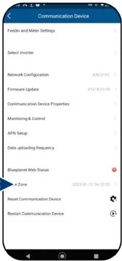
Fig. 47. Connection to the Communication unit established.
Fig. 46. Confirm inverter hotspot
9.7 Menu of the Communication unit
Note: In both cases you now have access to the Communication unit.
This is where you can make settings that do not directly affect the function of the inverter.
For initial start-up, we recommend calling up the following parameter:
- Set timezone. See chapter 9.8.1
- Set the same country and grid type for every connected inverter. (Observe local network requirements!) See chapter 9.8.5
- View live values of the customer's PV installation in order to detect faults, if necessary. Adjust other parameters, if necessary. See Chapter 9.6.4.
- Set up monitoring & control. See Chapter 9.8.2 on page 32.
Note: After completing or exiting initial start-up, the serial-number-based password is required to set further parameters. See Chapter 9.12.6 on page 37.

Fig. 48. Menu of the Communication unit
9.7.1 Setting the time zone
Note: The time communicated by the network is GMT. You should now adjust the time zone depending on the installation location. This time is also used for the display on the "blueplanet web" portal.
- Select time zone. For Germany, this would be Amsterdam, Berlin...
- Save the selection with
.
Note: If the internet is not available on the network, you will have to make the changeover to summer/wintertime manually.
» Time zone set.
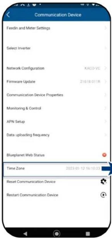
Fig. 49. Menu of the Communication unit

Fig. 50.Set time zone
9.7.2 Dynamic feed-in
∪
The connection shown in the block diagram Fig. 53 has been established.
Note: For more information, see Chapter 9.16 on page 52.
- Select menu item
. - Select smart meter model >> SDM230
- Switch on
when the meter is connected. - Switch on
when the meter is connected. - At
, set the maximum power which the device may feed into the grid.
Note: This setting is only possible under 2 conditions:
- Meter model connected to the device.
is enabled in the menu under . - Start the function with
. - Please remedy if these conditions are not met. See Chapter 9.13 on page 39
» Dynamic feed-in is selected.


Fig. 51. Select feed-in and meter settings
Fig. 52. Select smart meter model and set max. feed-in power
![graph LR A["Netz"] --> B["Eastron 1ph smart meter"] B --> C["Last"] C --> D["Kaco device"] D --> E["RS485 kit"] E --> F["Router"] E --> G["Web Portal"] B --> H["B-,A+(G)"] H --> I["RS485 verdrillte 2-paarige Leitung"] D --> J["Master blueplanet 3.0 - 5.0 NX1 M2"]](/content/2026/06/1366546/images/634b205ba335b71bef3ba4fc58b51210e9003882e3b8c7fca81a87484d0e6d85.jpg)
Fig. 53. Block diagram for dynamic feed-in
9.7.3 Configure network parameter
Note: Here you can assign a static IP address to the inverter so that your router always uses the same address.
○ Connection to the device established
- Select
. - Activate
for automatic IP address assignment or for greater security: - Deactivate
and enter the IP address for your inverter. - Optional: Activate
and enter the primary DNS address. - Save settings with
button.
» IP settings made successfully.


Fig. 54.View device parameters
Fig. 55.View all parameters

Fig. 56.Set IP address
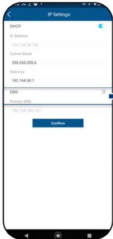
Fig. 57.Activate DNS
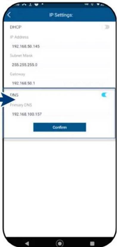
Fig. 58.Set DNS address
9.7.4 Monitoring and control
The
Note: The signal is transmitted via an installed RS485 line.
- Select
mode: : data from connected devices is uploaded to the KACO cloud server for evaluation. -
: local operation mode without further communication. (Standard) -
Confirm the selection with
.
» Operation mode set.
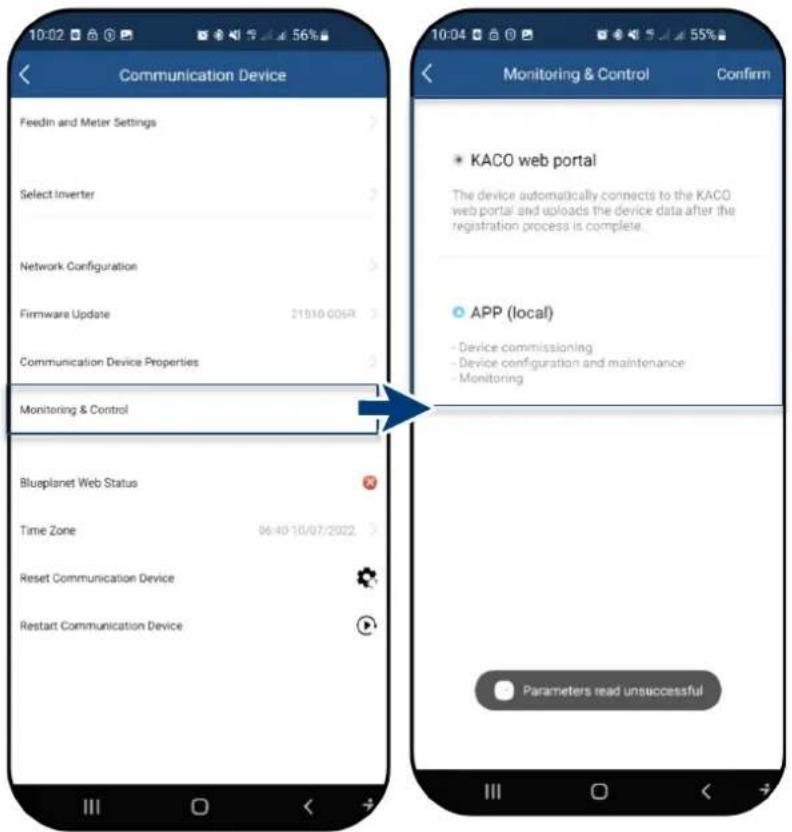
Fig. 59. Select monitoring & control
Fig. 60.Select mode
9.8 Additional functions
9.8.1 Changing the customer WLAN network
○
Note: This allows you to change the WLAN configuration when you replace the device, router or your mobile device.
- Open
. - Select the network in the
field using the drop-down menu. - Enter the password for the network and save the change with
.
Note: If the router is defective or no longer reachable and the Communication unit cannot establish a connection and the blue LED lamp on the Communication unit does not light up, you can find the SSID of the Communication unit hotspot with the serial number of the Communication unit in your WLAN list. You can establish a connection with the hotspot of the Communication unit by entering the registration code on the label as a password.
Note: Data is transferred after approx. 30-60 minutes.

Fig. 61. Network properties
Fig. 62. Change network
9.8.2 Showing details of the WLAN connection
∪
- First, check the quality of the WLAN connection in
. If this is marked as "Strong", you have an optimal connection.
Note: Problem-free communication is only ensured if the signal quality is good. If necessary, improve the signal quality by decreasing the distance from the device and by removing objects which cause interference. - View the software version number of the Communication unit and the hardware version.
- Adjust the IP setting if DHCP detection does not work. See 9.7.3 on page 33
» Details of the WLAN connection have been viewed.

Fig. 63.View details of the WLAN connection

Fig. 64.Set static IP address
9.8.3 Resetting a faulty connection
○
Note: The Communication unit is restarted via the
- Press the
button in the warning message to trigger a restart.
Important: Pressingresets all created configurations to the factory defaults. - Reset the Communication unit with
.
» Check the connection after restart.


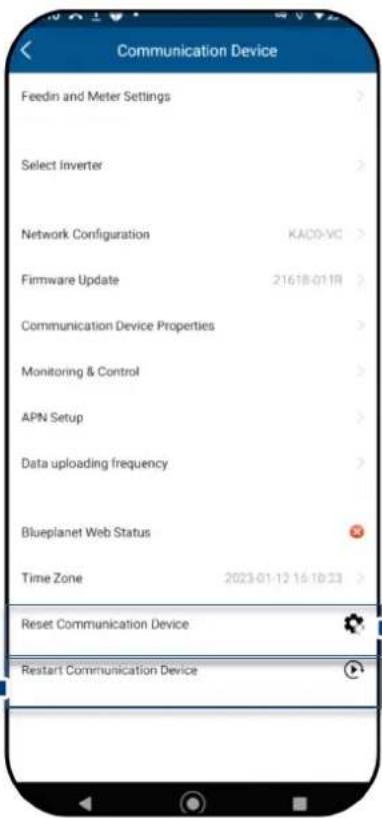
Fig. 66. Reset / restart the Communication unit

Fig. 67. Observe the note on resetting the Communication unit!
Fig. 65. Note for

NOTE
The following settings are reset when the communication unit is reset:
• Network configurations
- Feedin and Smart-Meter Settings
• Function Monitoring & Control
- Time Zone
- Internal inverter list from the communication unit is deleted from the memory.
Note: Inverter settings are not reset by the communication unit during a restart.
9.8.4 View available inverters
All inverters are connected via a communication unit.
- Select the required
under .
Note: Up to 5 inverters can be connected to one Communication unit. - Adjust the parameters in
. see Chapter 9.11 on page 39 or:
- View feed-in values of the selected device in
>> see Chapter 9.9.1 on page 37
» Device configured with country setting.
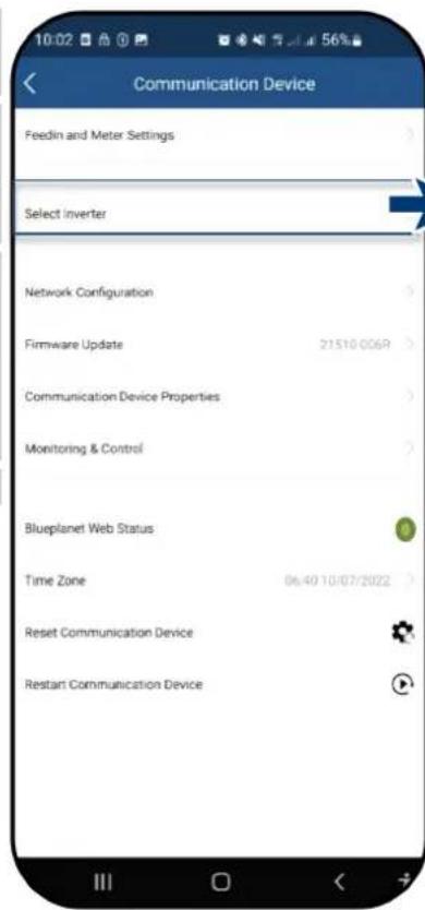
Fig. 68.Select inverter

Fig. 69. Select the required inverter
9.9 Menu of Inverter
9.9.1 Viewing the Instantaneous values
The required device is selected in
- Select < Instantaneous values> and view information about the installation.
Note: All measured values for your PV system and the grid power are displayed. In addition, after solar feed-in, the daily values and yields are displayed.
Note: The measured values are only displayed for the selected device. A simultaneous evaluation of all inverters can only be carried out via our "blueplanet web" monitoring portal.
-
View current Power and Power Factor.
-
View pending errors via
. N/A = no error
Note: In the event of a pending error, note the Error code list in chapter 10.5 on page 57.


Fig. 70. Viewing the live values
Fig. 71. Overview of power values
9.9.2 Authorisation to change parameters
- Open
to set the parameters for initial start-up.
Important: No password is required for initial parameter setting.
A password must be entered if it becomes necessary to change the parameters of the device after initial start-up (security function). The specific password for the inverter must be requested from KACO Service.
- Enter the password in the
field and confirm with .
Warning
Please complete the configuration completely before exiting the configuration mode.

Confirm
Fig. 72. Warning issued only on the first accidental abort attempt.

Fig. 73.Select parameter settings
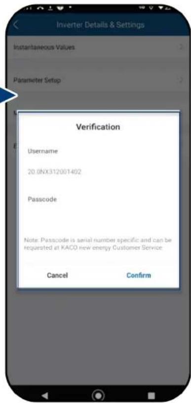
Fig. 74. Authorisation required
9.9.3 Selecting country and grid type
The required device is selected in
- Select
.
Caution: The following settings can only be made once without a password during initial start-up!
- Select the operator country and grid type in the field according to the grid operator requirements and confirm with
.
Note: By default, all required parameters are activated via the relevant grid code.
Note: When the grid standard has been changed, the device carries out a self-test. As a result, around 2 minutes may elapse before the device feeds in again.
Note: Further grid standards settings can be made if requested by the grid operator or customer (e.g., setting for reactive power, Q(U) curve, see Chapter 9.13.1).
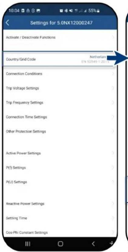

Fig. 75. Check or change country and
Fig. 76.Select country & grid code
grid-type
9.10 Operation mode
9.10.1 Operation mode for normal operation
You have made all the necessary basic settings.
- Switch to
to view the menu of an .
Note: As soon as the device appears, it can be selected immediately without having to wait for the search to finish (even if the screen is greyed out).
2 Now view all entries under
» The Communication unit is connected to your mobile end device.


Fig. 77.Select operation mode
Fig. 78. Select inverter
9.11 Enabling functions

NOTE
You will find a description of the individual functions starting in Chapter 9.13.1 from page 40. Further parameters are also being added continuously in the successive firmware versions. For this reason, see the PDF version of these application instructions for important additions.
The menu is opened.
- Call up
via under - After the setting has been made in the respective parameter, the function can be enabled (see references).
- Active power regulation (see Chapter 9.13.6 on page 42)
- 70 % rule (for details, see Chapter 9.17 on page 52)
- Active power rampup (see Chapter 9.13.6 on page 42)
- P(U) (see Chapter 9.13.8 on page 44)
- P(f) (see Chapter 9.13.7 on page 43)
- Reactive power control (see Chapter 9.13.9 on page 45)
- LVRT (Low Voltage Ride Through) – This is a requirement that generation units remain on the grid and are not switched off in the event of a short-term voltage drop.
- Overvoltage trip-off (10 min average) – protective function
- Islanding detection – protective function
- Monitoring of N-PE voltage – ground fault protective function
-
Active power increase with underfrequency P(f)
-
Confirm selection with
. The device then performs a restart with the desired range of functions.
» The desired functions are permanently set.

Fig. 79.Select inverter
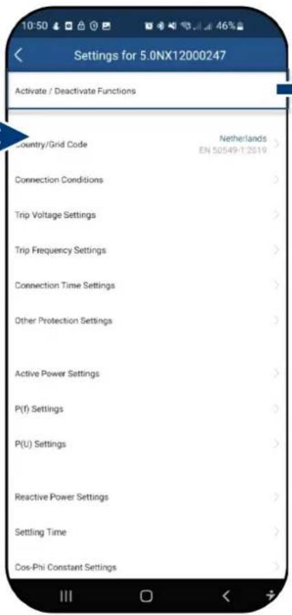
Fig. 80. Enable/disable functions

Fig. 81. Toggle required functions
9.11.1 Connection conditions
Note: The suitable voltage and frequency range of grid operation can be set in accordance with the requirements of the local grid operator.
The
Select
Set parameters for min./max. start voltage and start frequency.
Save settings with
Grid parameters set.

Fig. 82.Connection conditions

Fig. 83. Setting grid parameters
9.11.2 Voltage shutdown settings
Note: There are three thresholds for overvoltage and undervoltage protection. The first threshold value indicates the lower range. The middle threshold range is freely adjustable. The third threshold value indicates the upper range.
The
- Select
. - Set min. and max. shutdown time with associated voltage for each phase.
- Save the settings with the
button.
» Voltage protection defined.

Fig. 84. Select voltage shutdown settings

Fig. 85. Define voltage range and shutdown times
9.11.3 Frequency shutdown settings
Note: There are three thresholds for overfrequency and underfrequency protection. The first threshold value indicates the lower range. The middle threshold range is freely adjustable. The third threshold value indicates the upper range.
The
1 Select
2. Set the thresholds.
Principle:
- First maximum threshold ≤ second maximum threshold ≤ third maximum threshold
- First minimum threshold ≥ second minimum threshold ≥ third minimum threshold
-
Trigger time for the first threshold ≤ trigger time for the second threshold ≤ trigger time for the third threshold
-
Save settings with
.
» Frequency protection defined.
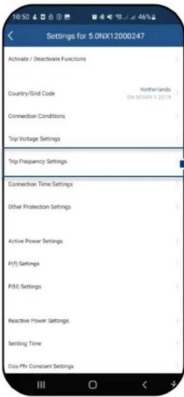
Fig. 86. Select frequency shutdown settings

Fig. 87. Set frequency range and ROCOF protection limit
9.11.4 Connection time settings
Note: Set monitoring time when one of the voltage and frequency values has been changed. If the measured values are within the range defined by the selected grid standard, the inverter can start or reconnect.
The
- Select
. - Set
for restart. - Set
. settings.
» Connection time defined.
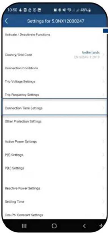
Fig. 88. Select connection time settings
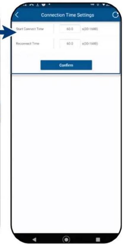
Fig. 89. Define start-up / reconnection time
9.11.5 Other protective shutdowns
Note: Further protective settings must also be made to protect your PV array from damage.
The
- Select
. - Specify the
. - Specify the
. - Set the
for error monitoring. - Save settings with
.
» Protective function set

Fig. 90. Call up other protective shutdowns
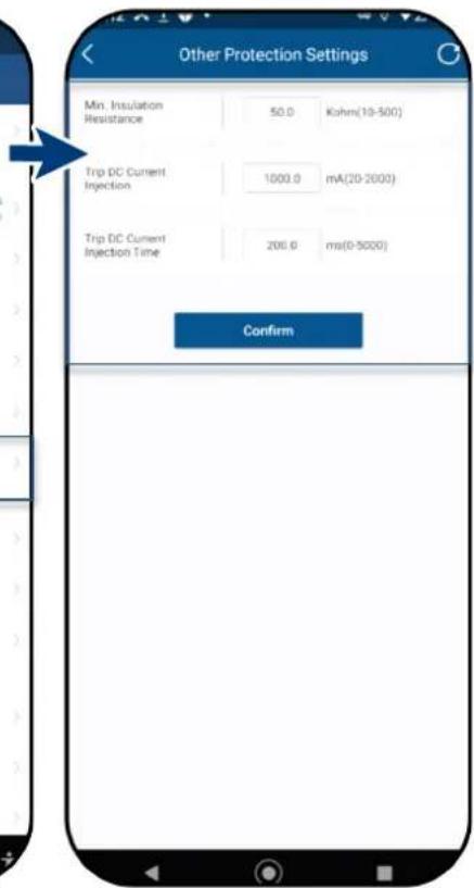
Fig. 91. Set insulation resistance and DC parameters
9.11.6 Active power settings (power limitation)
Note: The output power of the device can be set permanently to a lower value than the maximum output power by the power limitation. This may be necessary in order to limit the maximum power rating of the system at the grid connection point, upon the grid operator's request.
The
- Select
.
Setdependent on Pn in %. - Set the
and of the active power. - Save settings with
.
Note: When switching to AC operation and control and when switching to energy generation mode, the active power generated by the device must not exceed a certain gradient expressed as a percentage of the nominal active power of the inverter per minute.
» Power limitation defined.

Fig. 92. Call up active power settings
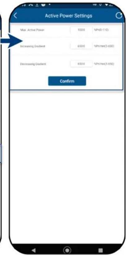
Fig. 93. Define max. AP & gradients
9.11.7 P(f) settings
Note: With a programmable frequency threshold with programmable P range, the inverter can activate the active power response to underfrequency.
The
- Select the
- Select mode > see note below on the 4 modes.
- Define frequency range.
- Set relative power reduction.
- Set internal delay time P(f).
- Define min. delay time for power reduction.
- Define power gradient after resetting the frequency.
» P(f) defined.
Legend for Fig. 96+Fig. 97: fn: Nominal frequency; freset: Reset frequency: fstart: Start frequency; fstop: Stop frequency; ΔP : Active power in % during reduction.

Note: The following 4 modes are available for selection:
- Fixed gradient and non-hysteresis: ΔP is the active power as a percentage of Pn; the inverter provides non-hysteresis in the control of active power response to overfrequency.
- Variable gradient and non-hysteresis: ΔP is the active power as a percentage of PM; the inverter provides non-hysteresis in the control of active power response to overfrequency.
- Fix gradient and hysteresis: ΔP is the active power as a percentage of Pn; the inverter provides hysteresis in the control of active power response to overfrequency
- Variable gradient and hysteresis: ΔP is the active power as a percentage of the PM; the inverter provides hysteresis in the control of active power response to overfrequency.
Note: The intentional delay time for P(f) is only used for the activation of the function in accordance with the frequency via fstart, whereby the intentional delay time plus own dead time must be smaller than 2s.
Note: The minimum delay time for enabling of the active power is the delay time during which the active power can increase once the frequency has fallen below freset.

Fig. 96.Non-hysteresis
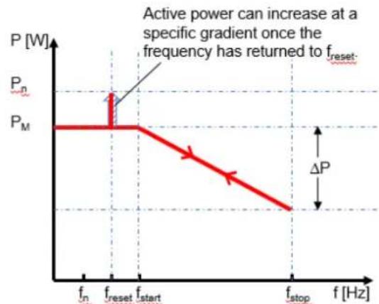
Fig. 97.Hysteresis
9.11.8 P(U) settings
Note: With a programmable voltage threshold with programmable P range, the inverter can activate the active power response to overvoltage.
The
- Select the
- Select mode > see note below.
- Define voltage range.
- Define relative power reduction.
- Set internal delay time P(U).
-
Define min. delay time for power reduction.
» P(U) defined. -
Define power gradient after resetting the frequency.
Legend for Fig. 100+Fig. 101 Un: Nominal voltage; Ureset: Reset voltage; Ustart: Start voltage; Ustop: Stop voltage; ΔP : Active power in % during reduction.

Fig. 98. Select the P(U) settings
Fig. 99. Set the P(U) parameters
Note: The following 4 modes are available for selection:
- Fix gradient and non-hysteresis: ΔP is the active power as a percentage of Pn; the inverter provides non-hysteresis in the control of active power response to overvoltage.
- Variable gradient and non-hysteresis: ΔP is the active power as a percentage of the PM; the inverter provides non-hysteresis in the control of active power response to overvoltage.
- Fix gradient and hysteresis: ΔP is the active power as a percentage of Pn; the inverter provides hysteresis in the control of active power response to overvoltage.
- Variable gradient and hysteresis: ΔP is the active power as a percentage of the PM; the inverter provides hysteresis in the control of active power response to overvoltage.
Note: The intentional delay time for P(U) is only used for the activation of the function in accordance with the voltage via Ustart, whereby the intentional delay time plus own dead time must be smaller than 2s.
Note: The minimum delay time for enabling of the active power is the delay time during which the active power can increase once the voltage has fallen below Ureset.

Fig. 100.Non-hysteresis
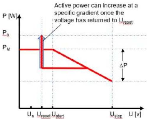
Fig. 101.Hysteresis
9.11.9 Reactive power operation mode
Note: Reactive power can be used in electrical energy supply networks to bolster the level of voltage. As such, feed-in inverters can contribute to statistical voltage stability.
The
- Select
. - Select control process > see basis and set subsequent processes
, ,
- Set
for selected control process.
Note: A change in the reactive power may be necessary in order to meet the requirements of a first-order filter.
» Reactive power process defined.

Fig. 102.Set the settling time

Fig. 103. Select reactive power settings

Fig. 104. Specify the operation mode
Basis
There are four types of reactive power control. Only one mode of operation can be active at any given moment.
From the perspective of the grid, the inverter behaves like a load in accordance with the national standard. This means that the inverter operates in quadrant II (under-excited) or III (over-excited) as shown in Fig. Fig. 105.
Definition
Over-excited reactive power, also known as capacitive reactive power or leading power factor.
Under-excited reactive power, also known as inductive reactive power or lagging power factor.

Fig. 105.Load reference arrow system
9.11.10 Cos-phi constant settings
Note: In cos φ constant mode, the specified power factor is permanently set by the inverter. In doing so, the reactive power level is set in line with Q=P*tan φ as a function of the power that continuously generates the specified power factor.
The
- Select
. - Set the
target value. - Select the excitation type from the drop-down field.
- Save settings with
.
» Cos-phi constant defined.

Fig. 106. Select the cos-phi constant
Fig. 107. Define the cos-phi target value
9.11.11 Q constant settings
Note: The target value of the reactive power can be adjusted depending on the set maximum apparent power.
The
- Select
.
- Set
in %.
- Select the excitation type from the drop-down field.
- Save settings with
.
» Q constant> defined.
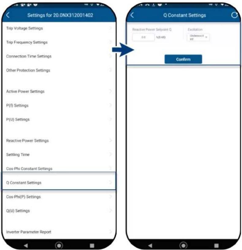
Fig. 108.Select Q constant settings
Fig. 109.Enter reactive power target value Q
9.11.12 Cos-phi (P) settings
Note: Power-based control cos φ(P) regulates the cos φ value of the power depending on the emitted active power.
4 coordinates can be set in order to map the P curve.
The
- Select
. - Define P/Pn, cos- φ ) and excitation for each of the 4 nodes.
- Set the
.
Note: Activation threshold as a percentage of Un corresponds to the "Lock-In" voltage.
4. Set the
Note: Deactivation threshold as a percentage of Un corresponds to the "Lock-Out" voltage.
» cos φ(P) defined.
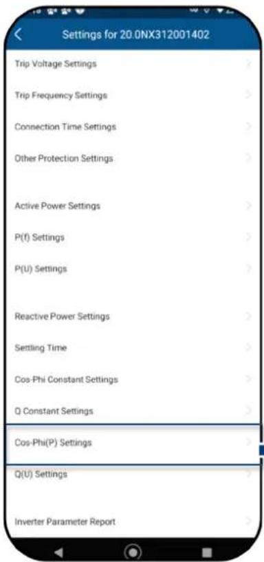

Fig. 110. Select cos-phi (P) settings
Fig. 111.Set cos-phi (P) parameters
Definition:
The coordinates are the active power as a percentage of Pn and the displacement factor cos- φ .
A grid operator can specify two voltage thresholds as a percentage of Pn to activate or deactivate the function. The voltage thresholds are normally referred to as the "Lock-In" and the "Lock-Out" voltage.
![| Point | P | cosφ | |-------|---------|--------| | [P₁,cosφ₁] | 0 | 1 | | [P₂,cosφ₂] | 1 | -1 | | [P₃,cosφ₃] | 2 | -2 | | [P₄,cosφ₄] | 3 | -3 |](/content/2026/06/1366546/images/26191d125d9e0c3f8198ff46da1f84e3ec23bd7863324e049504c9a4f4648fae.jpg)
Fig. 112. Cos-phi(P) curve
9.11.13 Q(U) settings
Note: Voltage-dependent control Q(U) regulates the reactive power output depending on the voltage.
4 coordinates can be set in order to map the curve.
The
- Select the
- Define U/Un, Q/Sn and phase for each of the 4 coordinates.
- Set the
in % of Pn.
Note: Activation threshold as a percentage of Pn corresponds to the "Lock-In" voltage.
- Set the
in % of Pn.
Note: Deactivation threshold as a percentage of Pn corresponds to the "Lock-Out" voltage.
» Q(U) curve defined.

Fig. 113.Select Set Q(U) settings

Fig. 114. Set the Q(U) parameters
Definition:
The coordinates are the voltage as a percentage of Un and the reactive power as a percentage of Pn.
A grid operator can specify two active power thresholds as a percentage of Un to activate or deactivate the function. The active power thresholds are normally referred to as the "Lock-In" and the "Lock-Out" active power.
![| Point | U | Q | |---|---|---| | [U₁,Q₁] | 0.5 | 1 | | [U₂,Q₂] | 0.75 | 1 | | [U₃,Q₃] | 0.9 | 0.5 | | [U₄,Q₄] | 1.0 | 0 | Over-excited (Q) for U > 0; Under-excited (Q) for U < 0; Over-excited (Q) for U > 0; Under-excited (Q) for U < 0; Over-excited (Q) for U > 0; Under-excited (Q) for U < 0.](/content/2026/06/1366546/images/535cf44c9abfee8c5f5f34ebc0e22878eb8e2504ae2de320089ac6f808cb01ec.jpg)
Fig. 115.Q(U) curve and non-hysteresis
![| Point | U | Q | |-------|-------|-------| | [U₁,Q₁] | 1 | 1 | | [U₂,Q₂] | 2 | 1 | | [U₃,Q₃] | 3 | 0 | | [U₄,Q₄] | 4 | 0 |](/content/2026/06/1366546/images/63a10e7a1e36691add1a08b14589d740a53fc978202032def4ef1750012788d6.jpg)
Fig. 116.Q(U) curve and hysteresis
9.11.14 Inverter parameter report
Note: Displays all set parameters in an overview list.
The
- Select
. - Check all set parameters.
- Export the set parameters using the
button. This serves as proof of all settings made with regard to the EVU.
» Parameter overview displayed.
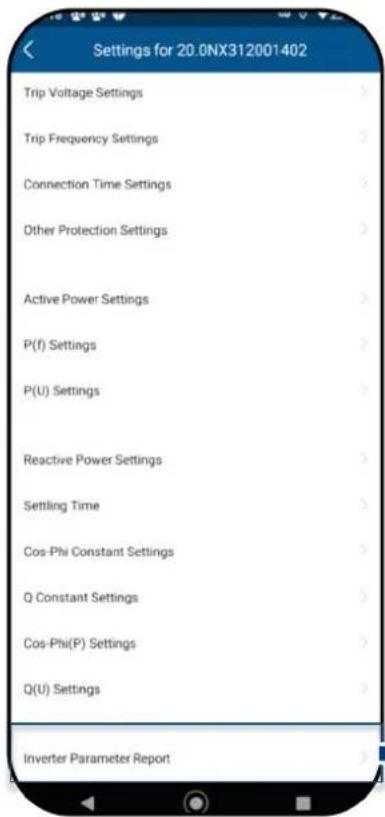
Fig. 117.View device parameters
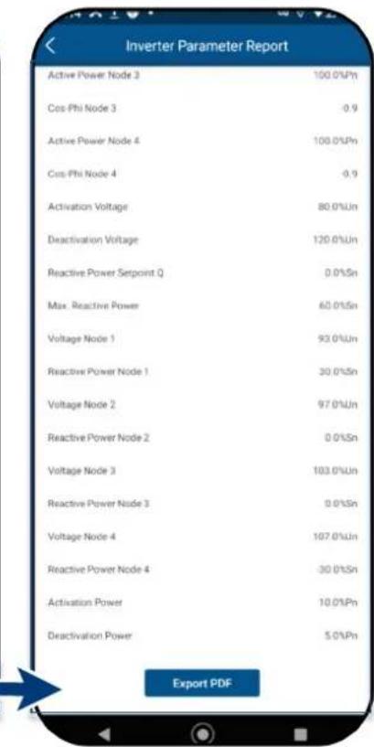
Fig. 118.View all parameters
9.12 Performing a firmware update
9.12.1 Updating the Communication unit
Note: The enclosed Communication unit is required in order to perform the update. The firmware update can only be carried out with adequate DC voltage (100 W).
The current firmware package is available at mykaco.com and does not correspond to the firmware version on the device(s).
1 Download the firmware "KACO_NX3_Vxx.zip" with the required *.bin files from mykaco.com under downloads and unpack.
-
Select
-
Select the tab
and press -
In the firmware path, select the new file Update.bin.
» After successful update, continue with the inverter firmware update.
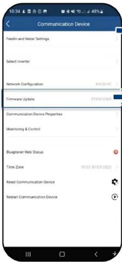
Fig. 119.Select firmware update
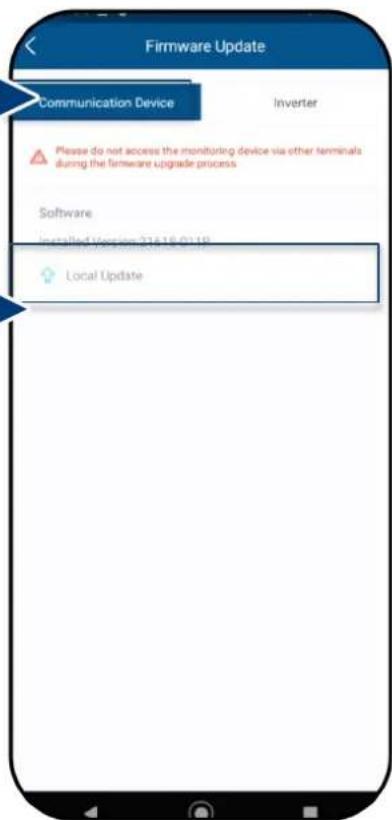
Fig. 120. Update the firmware for the Communication unit
9.12.2 Update the inverter

NOTE
Make sure that there is sufficient DC power (100 W). Also note that the sequence of the firmware update for the associated *bin files must be observed. This process takes approx. 10 minutes. The files must not be renamed.
Before updating the inverter, the firmware of the Communication unit needs to be updated.

NOTE
With the Communication unit plugged in, no communication via RS485 is possible during the firmware update.
The firmware update for the Communication unit has been carried out successfully.
- Select
. - Select the
tab and call up for inverters. - In the firmware path, locate and open the file masterVxxx-xxxxx-xx.bin. The upload begins.
- Open
for the file. - In the firmware path, locate and open the file safetyVxxx-xxxxx-xx.bin. The upload begins.
- After completing the update, check the uploaded firmware versions of each *bin file against the version in your firmware path. Repeat the corresponding process if any deviation is found.
- The upgrade process must be confirmed.
Caution: During the upgrade, the info – Update in progress – is displayed. Only after restarting the device does the message appear – Update completed successfully.
» Following successful update, the device is ready for operation.

Fig. 121.Select firmware update

Fig. 122. Select firmware update for inverters

Fig. 123. Firmware for inverters and associated security update
9.13 Monitoring with "blueplanet web"
Note: You will find the portal under: https://kaco-newenergy.com/de/blueplanet-web/.
- Select "Register PV system free of charge in blueplanet web public".
- From the drop-down menu, select
. - Registration is carried out via the
button, or with an existing account via .
Note: Data is transferred after approx. 30-60 minutes.
Note: After successful connection, the LED
Note: The portal version
Registration entry in the monitoring tool Depending on the software package on your device, o serial numbers may need to be entered!
SW package < R006 inverter serial number - Reg.
SW package > R006 serial number from WiFi stick-
Data logger
Inverter serial number(s)*:

123
Fig. 124. Registering via KACO blueplanet web public
9.14 Monitoring the device
You can monitor the device via the external Communication unit. The operating data of the device can also be transferred to the cloud. You can also view all data with the "KACO NX Setup" app.
Each device has a communication unit. If the same devices are installed in the same location, the devices can be connected using the RS 485 cable and share a communication unit. Please note that a maximum of 5 devices can be connected to each Communication unit.
![graph LR A["blueplanet web"] --> B["Cloud"] B --> C["Internet"] C --> D["Router"] D --> E["WiFi 2.4G"] E --> F["PV module"] F --> G["Inverter with communication device"] G --> H["AC 1ph/N (L1)"] H --> I["AC 1ph/N(L2)"] I --> J["Inverter with communication device"] J --> K["AC 1ph/N(L3)"] K --> L["Co…](/content/2026/06/1366546/images/245642282fe08af7c9801aa3ebcccc0ce52e1fc202eb3631edd29379fd31cb38.jpg)
Fig. 125. Installation monitoring of up to 5 inverters with Communication unit
9.15 Active power control with a Smart-Meter
The device can control the active power delivered via a connected Smart-Meter. The following image shows the connection mode of the system via a communication unit.
![graph LR A["blueplanet web"] --> B["Cloud"] B --> C["Internet"] C --> D["Router"] D --> E["WiFi 2.4G"] E --> F["PV module"] F --> G["Inverter with communication device"] G --> H["Modbus RTU RS485 bus"] H --> I["PV module"] I --> J["Inverter without communication device"] J --> K["Modbus RTU RS485 bu…](/content/2026/06/1366546/images/37742dc46a7b1be4724b815c18b2fe6434a117d0fe8e89e5bc8709b698178cc3.jpg)
Fig. 126. System for active power control with Smart-Meter
Connection method with Smart-Meter as shown above via SDM630. For the Modbus and setting the baud rate method for ModBus, see the corresponding user manual.
9.16 Information on dynamic feed-in
9.16.1 Control behaviour
With a system output of 7 kWp and above, a digital feed-in meter or a remote control option is still mandatory at present. Active power limitation is the simplest option here. This can be achieved for all NX3 devices via the Smart-Meter or a data logger.
With EEG 2023, the expansion of photovoltaics is to become a topic of overriding public interest. Therefore, new PV systems that are connected to the grid on or after 1 January 2023 and have a capacity of up to 25 kW will be subject to the maximum generation. This involves abolishing the 70% limit on the nominal power that may be fed into the public grid. Consequently, a solar generation meter (Smart-Meter) is no longer necessary.
9.16.2 Increasing the active power limitation
For the feed-in limit to be raised above 70%, a smart meter or data logger must be connected. The total consumption is communicated to the inverter/data logger by the additional Smart-Meter (3-phase) so that it can establish a new maximum feed-in power.
If the feed-in power of a PV system is compared with the consumption of a detached home, a graph such as the following example is produced.
![| Hour | Power [kW] | |------|------------| | 00:00 | 0 | | 02:00 | 1 | | 04:00 | 0 | | 06:00 | 0 | | 08:00 | 2 | | 10:00 | 5 | | 12:00 | 8 | | 14:00 | 9 | | 16:00 | 7 | | 18:00 | 3 | | 20:00 | 1 | | 22:00 | 0 | Uhrzeit [hh:mm] | 2, 3, 4, 1, 2, 3, 4, 7, 8, 9, 10 |](/content/2026/06/1366546/images/e1a258ac693fe4c48b2b3ae99c8e8ca9de5e0162a41fad34a971b568a930627f.jpg)
Fig. 127. Diagram comparing the energy requirement of a detached home and PV output
| Legend | |||
| 1 | Energy requirement of a detached home | 3 | 70% feed-in power (yellow area) |
| 2 | 70% fixed feed-in limit (grey line)– regulation command to inverter | 4 | Lost feed-in power (red area) |
It is evident that there is a constant base load, especially at night (continuous/standby operation of consumers).
Based on this graph, we can now see that the actual self consumption values communicated should result in considerably less power being lost from the PV system.
![| Time | Power [kW] | | -------- | ---------- | | 00:00 | 7 | | 02:00 | 7 | | 04:00 | 7 | | 06:00 | 7 | | 08:00 | 9 | | 10:00 | 7 | | 12:00 | 95 | | 14:00 | 7 | | 16:00 | 7 | | 18:00 | 95 | | 20:00 | 7 | | 22:00 | 7 | | 00:00 | 7 |](/content/2026/06/1366546/images/d5483e0c541cbab1693df4caed6c41d80e1f8914cfe6d96925d930adff6ceed9.jpg)
Fig. 128. Diagram of increase in self consumption
| Legend | |||
| 1 | Regulation command to device 70% + self consumption | 3 | PV power gained through self consumption |
| 2 | Energy requirement of a detached home (green area) | 4 | PV power lost despite self consumption |
Using the feed-in meter/data logger for calculations allows more efficient use to be made of the PV system, thus providing more energy for self-consumption.
Graph Abb. 145 also shows that a red area (lost energy) is nevertheless produced because the amount of power consumed by the owner has fallen to 0 but the PV system could provide more electricity. When the self consumption falls to 0 kW, the 70% regulation function takes effect again.
The 0% feed-in regulation, on the other hand, must ensure that there is no feed into the public grid. Depending on the self consumption, the PV system output may be connected up in such a way that the user can make use of the energy generated themselves and nothing has to be purchased from the public grid.
The feed-in meter must therefore be connected to the data logger so that the logger can generate the regulation commands. If an energy meter is not connected to the data logger, the logger continuously sends a regulation command to the inverters with a 0% feed-in maximum. This means that feed-in may not take place.
![| Hour | Peak 1 Power [kW] | Peak 2 Power [kW] | Peak 3 Power [kW] | |------|-------------------|-------------------|-------------------| | 14:00 | 10.0 | 8.5 | 0.0 | | 16:00 | 7.0 | 0.0 | 0.0 | | 20:00 | 0.0 | 0.0 | 7.0 | | 22:00 | 0.0 | 0.0 | 1.0 |](/content/2026/06/1366546/images/a3b27dbce1fe8311ca655ddead2767794ff0d860aeba4fc087b43a62ce3e7923.jpg)
Fig. 129. Diagram of 0% regulation
| Legend | |||
| 1 | PV power available (red area) | 3 | Bought-in power (yellow area) |
| 2 | Energy requirement of a detached home (green area) | ||
By connecting up additional consumers, heating, water or energy storage systems, the self consumption and therefore the consumption of the PV current can be increased considerably.
This function can however only be used by data logger because this has an SO output and could therefore connect up additional consumers via a relay circuit.
10 Maintenance and troubleshooting
10.1 Visual inspection
Inspect the product and cables for visible external damage and note the operating status display, where applicable. In case of damage, notify your installer. Repairs may only be carried out by an electrician.
! DANGER
Dangerous voltage due to two operating voltages!
Removing the plug connections before disconnecting the device from the PV generator may lead to injuries and damage the device.
During installation: Electrically disconnect the DC positive and DC negative from the protective earth (PE).
Disconnect the device from the PV generator using the integrated DC isolator switch.
Remove the plug connector.

! DANGER
Dangerous voltage due to two operating voltages
Coming into contact with the lines and/or terminals/busbars in the device can cause serious injury or death. The discharge time of the capacitors is up to 5 minutes.
Only appropriately qualified electricians authorised by the mains supply network operator are permitted to open and maintain the device.
Before opening the device: Disconnect the AC and DC side and wait at least 5 minutes.

NOTE
The housing of the device does not contain any components which can be repaired by the customer.
Do not attempt to repair faults that are not described here (in the chapter on troubleshooting and fault rectification). Contact our customer service department. Only perform the maintenance work that is described here.
The device should be checked for proper operation by a qualified electrician at regular intervals and if you experience problems, you should always contact the system manufacturer's Service department.
10.2 Cleaning
10.2.1 Cleaning the housing

! DANGER
Danger of death due to penetrating fluid
Serious injuries or death can result if moisture enters the system.
Only use completely dry objects to clean the device.
The device should only be cleaned from the outside.

CAUTION
Do not use compressed air or high-pressure cleaners!
If the device is contaminated, only clean the housing, cooling fins, housing cover with water and a cloth.
1 Use a vacuum cleaner or a soft brush to remove dust from the top of the device on a regular basis.
2 Remove dust from the ventilation inlets if necessary.
10.2.2 Cleaning the heat sink
The housing of the device does not contain any components that can be repaired by the customer.
Do not attempt to repair faults that are not described here (in the chapter on troubleshooting and fault rectification). Contact our customer service department. Only perform the maintenance work that is described here.
The device should be checked for proper operation by a qualified electrician at regular intervals and if you experience problems, you should always contact the system manufacturer's Service department.
Device switched off at integrated DC isolator switch and AC switch.
Keep a suitable brush ready for cleaning.
1 Clean the free space between the cover and the heat sink using suitable brushes.
2 Clean the heat sink for the air inlet and outlet with a suitable brush.
NOTE: Do not use any aggressive cleaning agents and ensure that no other components come into contact with fluids.
» Cleaning completed

NOTE
Refer to our service and guarantee conditions on our website.
- T he cleaning intervals must be adapted to the environmental conditions of the installation site.
In sandy environments, we recommend cleaning the heat sinks every three months.
10.3 Shutting down for maintenance work / troubleshooting


DANGER
Lethal voltages are still present in the connections and cables of the device even after the device has been switched off and disconnected!
Coming into contact with the lines and/or terminals/busbars in the device can cause serious injury or death.
Only appropriately qualified electricians authorised by the mains supply network operator are permitted to open and maintain the device.
Comply with all safety regulations and current technical connection specifications of the responsible power supply company.

NOTE
If the error status lamp lights up, follow the instructions in the Chapter 10.5 on page57.
NOTE: Shutdown sequence.
1 Switch off the grid voltage by turning off the external circuit breakers.
2 Switch off the DC supply using the DC isolator switch.
DANGER! The DC cables are still live!
» After shutdown, wait 5 minutes before replacing the device.
10.4 Troubleshooting
In
| Error code | “N/A” is displayed here if no error has occurred. |
10.5 Error code
The following solutions are recommended when the error code is displayed:
| No.:‘ Description | |
| Step | LED not illuminated/no power output |
| 1 | Make sure that the DC isolator switch on the device is in the “1” or “ON” position. |
| 2 | Use a multimeter to check the polarity of PV+ and PV-. The red measuring probe is connected to the positive pole, the black probe to the negative pole. The value should be positive. |
| 3 | Using the multimeter, check whether the DC voltage lies within the voltage range of the inverter or not. |
| 4 Make sure that the DC solar plug connection is not loose. | |
| 5 | Use an energy meter or a clamp meter to check whether the inverter starts up. If the device starts up, the cause may be an internal short-circuit in the communication cable. |
| No.: Description | |
| Step AC/DC terminals melted | |
| 1 | It is necessary to tighten the terminals in order to establish the connection. Then, use external force to check whether the connection has loosened. |
| 2 | Take care that the cables and terminals are not subjected to excessive loads. |
| No.: E03-E05 | Description |
| Step E03: Relay test failedE05: Result of the automatic test function failed | |
| 1 | Disconnect device via the AC isolator switch and measure the AC voltage with a multimeter. The voltage between the line and the neutral conductor should be approx. 230 V and the voltage between the neutral conductor and earth within 20 V. |
| 2 | If the measured voltage is abnormal, the error is caused by the system voltage. If the measured voltage is normal, please switch the AC isolator switch on and continue with the next step. |
| 3 | Measure the AC voltage UL1-N, UL2-N, UL3-N, UN-PE using a multimeter. |
| 4 | If the measured voltage is normal, there is an error in the device. Please contact customer service to replace the device. |
| 5 | If the measured voltage is abnormal, please check the isolator switch and the cable (wiring error, loose connection, short-circuit, insulation etc.). |
| No.: E46 Description | |
| Step High MPPT voltage value | |
| 1 | When installing the device, measure the DC voltage with a multimeter to ensure that the voltage lies within the MPPT voltage range. |
| 2 | If the DC voltage exceeds the MPPT voltage range, please reconfigure the PV modules. If the DC voltage is within the MPPT voltage range, please replace the device. |
| 3 | If the error is reported for a limited period of time and the device regenerates, the cause is the detection of abnormal device data. |
| 4 | If the device does not recover, please switch the DC and AC power supply off, wait 5 minutes and then restart. If the error cannot be remedied, please replace the inverter. |
| No.: E34/E48 Description | |
| Step E34: AC voltage outside the rangeE48: Average voltage of the last ten minutes fault | |
| 1 | Switch the AC isolator switch off and measure the AC voltage. The voltage between the line and the neutral conductor should be approx. 230 V and the voltage between the neutral conductor and earth within 20 V. |
| 2 | If the measured voltage is abnormal, the error is caused by the grid voltage. If the measured voltage is normal, please switch the isolator switch on and continue with the next step. |
| 3 | Measure the AC voltage UL1-N, UL2-N, UL3-N, UN-PE using a multimeter. |
| 4 | If the measured voltage is normal, there is an error in the device. Please contact customer service to replace the device. |
| 5 | If the measured voltage exceeds the safety requirements, please check the system voltage. |
| No.: E35 Description | |
| Step Loss of supply power | |
| 1 | If the device error disappears and the device can be connected to the grid, please check whether an circuit breaker is installed on the AC side. |
| 2 | If the error occurs constantly, please disconnect the AC circuit breaker and measure the AC voltage. The voltage between the line and the neutral conductor should be approx. 230 V and the voltage between the neutral conductor and earth within 20 V. |
| 3 | If the measured voltage is lower than 20 V, the error is caused by the system voltage. If the measured voltage is normal, please switch the circuit braker on and continue with the next step. |
| 4 | Measure the AC voltage UL1-N, UL2-N, UL3-N, UN-PE using a multimeter. |
| 5 | If the measured voltage is normal, there is an error in the device. Please contact customer service to replace the device. If the measured voltage exceeds the safety requirements, please check the system voltage. |
| No.: E36/E38 Description | |
| Step | E36-GFCI failure / E38--ISO error |
| 1 | This error occurs if the device determines that the system leakage current exceeds the requirements of the safety standards (200k Ohms). |
| 2 | Please check whether the fault occurs in wet and rainy weather. Also check whether the fault disappears when the weather is dry and sunny. If this is not the case, the device is not the cause of the fault. |
| 3 | Using a multimeter, check whether the voltage PV+ and PV+ to earth is normal. It should be half of PV+ and PV-. Connect the strings individually to check which string is causing the error. |
| 4 | Carry out a visual inspection of all PV strings and connections and make sure that the grounding is reliable. |
| 5 | If there is a device of the same model in operation on site, use it to replace the failed device and check whether the failure was caused by the device. |
| No.: E37 Description | |
| Step PV overvoltage | |
| 1 | This error occurs if the device determines that the DC input voltage exceeds the maximum DC voltage of the device. |
| 2 | Remove all strings from the device and use the multimeter to measure the voltage between PV+ and PV- for each string. The total voltage must not exceed the maximum DC voltage of the device. |
| 3 | If the measured voltage is normal, there may be an error in the device. Please contact customer service to replace the device. |
| No.: E40 Description | |
| Step Overtemperature in the device | |
| 1 | This error occurs when the sensor detects a high temperature in the device. |
| 2 | Check for foreign bodies in the fan or heat sink of the device which could be the cause of overtemperature in the device. |
| 3 | Please check the ambient temperature when installing the device (below 40 °C) and do not expose the device to sunlight. If the error cannot be remedied, please contact customer service to replace the device. |
| No.: E65 Description | |
| Step PE connection error | |
| 1 | This error occurs when the inverter detects overvoltage in the N-PE. |
| 2 | Using the multimeter, measure the N-PE voltage of the device. |
| 3 Ensure that | N and PE are not reversed. |
| 4 | If necessary, deactivate thefunction (See Fig. 81 on Page 39) in the APP to hide the error message. |
| No.: W165 Description | |
| Step | PE connection error |
| 1 | This error occurs when the inverter detects overvoltage in the N-PE. |
| 2 | Using the multimeter, measure the N-PE voltage of the device. |
| 3 | Ensure that the earth cable is firmly connected and that the connection area is sufficient. |
| 4 If the error persists, please contact KACO new energy customer service. | |
10.6 Fault during connection set-up and search
Note: If there is a timeout or a communication failure with its WLAN network, the APP may freeze in an unwanted manner.
We recommend the following approach:
- Check the WLAN connection on the mobile end device. If the connection has been lost, reactivate it in the device settings. The window of the "KACO NX Setup" APP has to be closed completely using the overview of all opened windows, so that the "KACO NX Setup" APP can be restarted.
- If necessary, restart the search using the "Scan" button.
- If the QR code is not recognized, a manual connection to the Communication unit can be established in the settings of the WLAN connection on the mobile end device. SSID: Serial number WIFI stick, password: Registration code (both printed on WIFI stick) see Fig. 38
Note: The current connection status can also be checked using the LEDs on the WIFI stick. To do this, check the signal status by referring to Chapter 9.5 on Page 27
» Faults have been corrected and the status LED on the Communication unit lights up continuously, signalling readiness for operation.
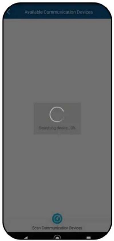
Fig. 130. Fault during connection &
search
10.7 Disconnecting connections
10.7.1 AC connection

Fig. 131. Detach AC connection plug

Fig. 132.Disconnect AC connection plug

Fig. 133.Detach cable
☐ Ensure that the device is completely free of AC/DC voltage.
1 Use a screwdriver (blade size 3 mm) to push in the catch on the coupling.
2 Unlock the plug connection and pull out the connector.
3 Unscrew the cable fitting.
4 Use a screwdriver to unlock the contact carrier on both sides.
5 Remove the contact carrier from the housing.
6 Loosen the screws on the contact carrier and remove the wires.
10.7.2 DC connection

! DANGER
Risk of DC plug connectors being destroyed!
DC plug connectors can be destroyed by an arc event if disconnected while still live. It is absolutely essential that the following shutdown sequence be carried out in the correct order:
- Use a clip-on ammeter to check that there is no current in any DC cables.
☐ Ensure that the device is completely free of AC/DC voltage.
Check that there is no current with a clip-on ammeter.
NOTE: Plug connectors may be unplugged under voltage, but never under load.
1 Use a screwdriver (blade width 3 mm) to push out the catch on the coupling.
2 Leave the screwdriver in place.
3 Disconnect the DC connector from the DC socket.
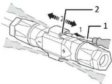
1 Screwdriver
2 Catch
Fig. 134. Detach AC connection plug
11 Decommissioning and dismantling
11.1 Switching off the device
! DANGER

Lethal voltages are still present in the connections and cables of the device even after the device has been switched off and disconnected!
Coming into contact with the lines and/or terminals/busbars in the device can cause serious injury or death.
The device must be mounted in a fixed position before being connected electrically.
Comply with all safety regulations and current technical connection specifications of the responsible power supply company.
The device is only permitted to be opened or serviced by a qualified electrician.
Switch off the grid voltage by turning off the external circuit breakers.
Check that all AC and DC cables are completely free of current using a clip-on ammeter.
Do not touch the cables and/or terminals/busbars when switching the device on and off.
Keep the device closed when in operation.

DANGER
Risk of DC plug connectors being destroyed!
DC plug connectors can be destroyed by an arc event if disconnected while still live. It is absolutely essential that the following shutdown sequence be carried out in the correct order:
Use a clip-on ammeter to check that there is no current in any DC cables.

WARNING
Risk of burns caused by hot housing components
Housing components can become hot during operation.
During operation, only touch the housing cover on the device.
11.2 Uninstalling the device
DANGER
Dangerous voltage due to two operating voltages
Coming into contact with the lines and/or terminals/busbars in the device can cause serious injury or death. The discharge time of the capacitors is up to 5 minutes.
Only appropriately qualified electricians authorised by the mains supply network operator are permitted to open and maintain the device.
Device disconnected and secured against restart.
1 Disconnect the AC connection plug from the device. AC connection [see section 10.6.1 on page 61]
2 Detach the DC cables from the DC plug connectors and furnish with protective caps. DC connection [see Section 10.6.2 on page 61]
3 Disconnect the Communication unit.
4 If present, remove the accessories: NX1 Smart Meter Connection Kit in reverse order as described in Chapter 7.8.
»The device has been uninstalled. Proceed with disassembly
11.3 Disassembling the device
Unit has been switched off and uninstalled.
1 Remove the screw that prevents the device from being lifted off the mount.
2 Use the lateral openings and lift the device off the mount.
» Device removed. Proceed with the packaging process.
11.4 Packaging the device
Device has been uninstalled.
1 If possible, always pack the device in the original packaging. If this is no longer available, an alternative is to use equivalent packaging.
2 The packaging box must be fully sealable and suitable for the weight and size of the device.
11.5 Storing the device

CAUTION
Property damage as a result of condensation
Incorrect storage can cause condensate to form in the device and impair the functionality of the device (e.g., storage outside the ambient conditions or temporary relocation from a cold to a hot environment).
- Store in accordance with the technical data > environmental data.
- Prior to installation, check the inner area for condensation and if necessary, allow it to dry sufficiently before installation.
Device packaged.
Store the device in a dry place in accordance with the ambient temperature range specified in the environmental data.
12 Disposal

CAUTION
Risk to the environment if disposal is not carried out in the correct manner
For the most part, both the device and the corresponding transport packaging are made from recyclable raw materials.
Unit: Defective devices and accessories must not be disposed of with household waste. Ensure that the old devices and any accessories are disposed of in a proper manner.
Packaging: Ensure that the transport packaging is disposed of properly.
13 Service and warranty
If you need help solving a technical problem with one of our KACO products, please contact our service hotline. Please have the following information ready so that we can help you quickly and efficiently:
• Device name / serial number
• Date of installation / Start-up report
- Error message shown on the display / Description of the error / Did you notice anything unusual? / What has already been done to analyse the error?
- Module type and string circuit
• Consignment identification / Delivery address / Contact person (with telephone number)
• Information about the accessibility of the installation site.
You will find the following information and other information on our website www.kaco-newenergy.com.
• our current warranty conditions,
- a complaint form,
- a form for registering your device. Please register your device without delay. In this manner, you can assist us in providing you with the quickest service possible.
14 Appendix
14.1 EU Declaration of Conformity
Head of R&D and Technology
i.V. Thomas Kittel
Head of Quality Management
KACO

new energy.
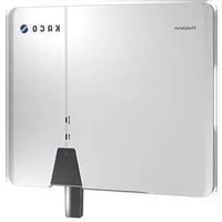

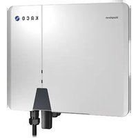

- MANUAL
- LEGAL PROVISIONS
- KACO WARRANTY
- DEFINITIONS ON PRODUCT DESIGNATIONS
- TRADEMARKS
- SOFTWARE
- PHOTOVOLTAIC FEED-IN INVERTER
- TABLE OF CONTENTS
- 1 GENERAL INFORMATION
- 1.1 NOTES REGARDING THIS DOCUMENT
- WARNING
- OTHER APPLICABLE DOCUMENTS
- RETENTION OF DOCUMENTS
- ORIGINAL VERSION
- 1.2 MORE INFORMATION
- 1.3 LAYOUT OF INSTRUCTIONS
- 1.3.1 SYMBOLS USED
- 1.3.2 SAFETY WARNINGS SYMBOLS GUIDE
- DANGER
- CAUTION
- NOTE
- 1.3.3 ADDITIONAL INFORMATION SYMBOLS
- 1.3.4 SYMBOLS FOR INSTRUCTIONS
- 1.4 TARGET GROUP
- 1.5 MARKING
- 2 SAFETY
- LETHAL VOLTAGES ARE STILL PRESENT IN THE CONNECTIONS AND CABLES OF THE DEVICE EVEN AFTER THE DEVICE HAS BEEN SWITCHED OFF AND DISCONNECTED
- 2.1 INTENDED USE
- 2.2 PROTECTION FEATURES
- 3 DESCRIPTION OF THE DEVICE
- 3.1 MODE OF OPERATION
- 3.2 SYSTEM LAYOUT
- 4 TECHNICAL DATA
- 5 TRANSPORTATION AND DELIVERY
- 5.1 SCOPE OF DELIVERY
- CHECK THE EQUIPMENT INCLUDED
- 5.2 TRANSPORTING THE DEVICE
- 5.3 INSTALLATION TOOL
- 6 ASSEMBLY AND PREPARATION
- 6.1 CHOOSING THE INSTALLATION LOCATION
- INSTALLATION SPACE
- INSTALLATION SURFACE
- 6.2 UNPACKING THE DEVICE
- RISK OF INJURY DUE TO EXCESSIVE PHYSICAL STRAIN
- 6.3 FASTENING THE MOUNT
- HAZARD WHEN USING UNSUITABLE FIXING MATERIALS
- POWER REDUCTION DUE TO HEAT ACCUMULATION
- 6.4 INSTALLING AND SECURING THE DEVICE
- LIFTING AND INSTALLING THE DEVICE
- THE MOUNT HAS BEEN INSTALLED
- PROPERTY DAMAGE AS A RESULT OF CONDENSATION
- 7 INSTALLATION
- 7.1 GENERAL INFORMATION
- 7.2 SURVEYING THE CONNECTION AREA
- 7.3 MAKING THE ELECTRICAL CONNECTION
- 7.3.1 REQUIREMENT FOR SUPPLY LINES AND FUSE
- 7.4 CONNECTING THE DEVICE TO THE POWER GRID
- 7.4.1 CONFIGURING THE AC CONNECTION PLUG
- 7.4.2 MAKE AC CONNECTION
- 7.5 CONNECTING THE PV GENERATOR TO THE DEVICE
- 7.5.1 CONFIGURING THE DC CONNECTOR
- RISK OF FATAL INJURY DUE TO ELECTRIC SHOCK
- CONNECTION AREA OPENED
- NOTE: BEFORE PROCEEDING WITH THE ISOLATION ENSURE THAT YOU DO NOT CUT ANY INDIVIDUAL WIRES
- 7.5.2 CHECKING THE PV GENERATOR FOR A GROUND FAULT
- ENSURE THAT THERE IS NO GROUND FAULT
- 7.5.3 RECOMMENDED STANDARD CONNECTION
- POSSIBLE CONNECTION
- NUMBER OF MODULES PER STRING
- 7.5.4 DESIGNING THE PV GENERATOR
- DAMAGE TO COMPONENTS DUE TO FAULTY CONFIGURATION
- TYPE AND CONFIGURATION OF THE PV MODULES
- DIMENSIONING THE PV GENERATOR
- 7.5.5 PV GENERATOR
- DAMAGE TO THE PV GENERATOR IN CASE OF FAULTY CONFIGURATION OF THE DC CONNECTOR
- CONNECTING THE PV GENERATOR
- CLOSING THE UNUSED DC CONNECTORS
- 7.6 CREATING EQUIPOTENTIAL BONDING
- 7.7 CONNECTING THE INTERFACES
- 7.7.1 CONNECTION FOR COMMUNICATION UNIT
- 7.8 CONNECTING THE SMART-METER FOR DYNAMIC FEED-IN
- 8 COMMISSIONING
- 8.1 REQUIREMENTS
- 8.2 PRECONDITIONS RELATING TO STANDARDS
- ATTACHMENT OF SAFETY LABEL IN ACCORDANCE WITH UTE C15-712-1
- 9 CONFIGURATION AND OPERATION
- 9.1 START CONDITION
- 9.2 INITIAL START-UP
- STEP 2: CONFIGURING THE COMMUNICATION UNIT AND INVERTER
- 9.3 AUTHORISATION
- 9.4 OPERATING SYSTEM AND SYSTEM CONFIGURATION
- 9.5 SIGNAL ELEMENTS
- 9.6 CONNECTING TO THE DEVICE
- 9.6.1 CONNECTING TO THE DEVICE FOR THE FIRST TIME
- 9.6.2 CONNECTING THE DEVICE VIA A HOTSPOT (ALTERNATIVE)
- 9.7 MENU OF THE COMMUNICATION UNIT
- 9.7.1 SETTING THE TIME ZONE
- 9.7.2 DYNAMIC FEED-IN
- 9.7.3 CONFIGURE NETWORK PARAMETER
- 9.7.4 MONITORING AND CONTROL
- 9.8 ADDITIONAL FUNCTIONS
- 9.8.1 CHANGING THE CUSTOMER WLAN NETWORK
- 9.8.2 SHOWING DETAILS OF THE WLAN CONNECTION
- 9.8.3 RESETTING A FAULTY CONNECTION
- 9.8.4 VIEW AVAILABLE INVERTERS
- 9.9 MENU OF INVERTER
- 9.9.1 VIEWING THE INSTANTANEOUS VALUES
- 9.9.2 AUTHORISATION TO CHANGE PARAMETERS
- 9.9.3 SELECTING COUNTRY AND GRID TYPE
- 9.10 OPERATION MODE
- 9.10.1 OPERATION MODE FOR NORMAL OPERATION
- 9.11 ENABLING FUNCTIONS
- THE MENU IS OPENED
- 9.11.1 CONNECTION CONDITIONS
- 9.11.2 VOLTAGE SHUTDOWN SETTINGS
- 9.11.3 FREQUENCY SHUTDOWN SETTINGS
- 9.11.4 CONNECTION TIME SETTINGS
- 9.11.5 OTHER PROTECTIVE SHUTDOWNS
- 9.11.6 ACTIVE POWER SETTINGS (POWER LIMITATION)
- 9.11.7 P(F) SETTINGS
- 9.11.8 P(U) SETTINGS
- 9.11.9 REACTIVE POWER OPERATION MODE
- BASIS
- DEFINITION
- 9.11.10 COS-PHI CONSTANT SETTINGS
- 9.11.11 Q CONSTANT SETTINGS
- 9.11.12 COS-PHI (P) SETTINGS
- 9.11.13 Q(U) SETTINGS
- 9.11.14 INVERTER PARAMETER REPORT
- 9.12 PERFORMING A FIRMWARE UPDATE
- 9.12.1 UPDATING THE COMMUNICATION UNIT
- 9.12.2 UPDATE THE INVERTER
- 9.13 MONITORING WITH "BLUEPLANET WEB
- 9.14 MONITORING THE DEVICE
- 9.15 ACTIVE POWER CONTROL WITH A SMART-METER
- 9.16 INFORMATION ON DYNAMIC FEED-IN
- 9.16.1 CONTROL BEHAVIOUR
- 9.16.2 INCREASING THE ACTIVE POWER LIMITATION
- 10 MAINTENANCE AND TROUBLESHOOTING
- 10.1 VISUAL INSPECTION
- DANGEROUS VOLTAGE DUE TO TWO OPERATING VOLTAGES
- 10.2 CLEANING
- 10.2.1 CLEANING THE HOUSING
- DANGER OF DEATH DUE TO PENETRATING FLUID
- 10.2.2 CLEANING THE HEAT SINK
- 10.3 SHUTTING DOWN FOR MAINTENANCE WORK / TROUBLESHOOTING
- 10.4 TROUBLESHOOTING
- 10.5 ERROR CODE
- 10.6 FAULT DURING CONNECTION SET-UP AND SEARCH
- 10.7 DISCONNECTING CONNECTIONS
- 10.7.1 AC CONNECTION
- 10.7.2 DC CONNECTION
- RISK OF DC PLUG CONNECTORS BEING DESTROYED
- 11 DECOMMISSIONING AND DISMANTLING
- 11.1 SWITCHING OFF THE DEVICE
- 11.2 UNINSTALLING THE DEVICE
- 11.3 DISASSEMBLING THE DEVICE
- 11.4 PACKAGING THE DEVICE
- 11.5 STORING THE DEVICE
- 12 DISPOSAL
- RISK TO THE ENVIRONMENT IF DISPOSAL IS NOT CARRIED OUT IN THE CORRECT MANNER
- 13 SERVICE AND WARRANTY
- 14 APPENDIX
- 14.1 EU DECLARATION OF CONFORMITY
Brand : Kaco
Model : blueplanet 5.0 NX1 M2
Category : Battery charger