
Archer C54 - Wi-Fi repeater TP-LINK - Free user manual and instructions
Find the device manual for free Archer C54 TP-LINK in PDF.


| Product Type | Wi-Fi Repeater |
| Brand | TP-Link |
| Model | Archer C54 |
| Wi-Fi Standards | IEEE 802.11a/b/g/n/ac |
| Frequency Bands | 2.4 GHz and 5 GHz |
| Maximum Speed | 300 Mbps (2.4 GHz) + 867 Mbps (5 GHz) |
| Ethernet Port | 1 x 10/100 Mbps |
| Buttons | WPS / Reset |
| Antenna Type | 2 x External Fixed Omni-Directional |
| Dimensions (W x D x H) | 86 x 58 x 32 mm |
| Weight | 200 g |
| Power Supply | 12V DC / 1A |
| Power Consumption | 8.4 W (max) |
| Wireless Security | WPA / WPA2-PSK, WPA3 |
| Operating Mode | Range Extender, Access Point |
| LED Indicators | Power, Ethernet, Signal Strength |
| Maintenance | Wipe with a soft, dry cloth |
| Safety Precautions | Keep away from water and heat sources |
| Spare Parts / Repairability | No user-serviceable parts; contact support for issues |
| General Information | Extends Wi-Fi coverage up to 300 m² |
Frequently Asked Questions - Archer C54 TP-LINK
User questions about Archer C54 TP-LINK
0 question about this device. Answer the ones you know or ask your own.
Ask a new question about this device
Download the instructions for your Wi-Fi repeater in PDF format for free! Find your manual Archer C54 - TP-LINK and take your electronic device back in hand. On this page are published all the documents necessary for the use of your device. Archer C54 by TP-LINK.
USER MANUAL Archer C54 TP-LINK
Chapter 1. Get to Know About Your Router ....3
- Product Overview....4 1.2. Appearance .... 4
1.2.1.Top Panel 4 1. 2. 2. The Back Panel.... 5 1. 2. 3. The Bottom .... 6
Chapter 2. Connect to the Internet .....7
2.1. Position Your Router 8 2.2. Connect to the Internet 9
- Wireless Router Mode....9
- 2.Range Extender Mode....11
- Access Point Mode.....12
Chapter 3. Log In to the Router .... 14
Chapter 4. Configure the Router in Wireless Router Mode ..... 16
4.1. Operation Mode 17 4.2. Network....17
4.2.1. Status....17 4.2.2. Internet 19 4.2.3. MAC Clone....25 4.2.4. LAN 26 4.2.5. IPTV....26 4.2.6. DHCP Server....27 4.2.7. Dynamic DNS 29 4.2.8. Static Routing....30
4.3. Wireless....31
4.3.1. Wireless Settings 31 4.3.2. Guest Network....33 4.3.3. Wireless Schedule 34 4.3.4. WPS 35 4.3.5. Additional Wireless Settings....37
- 4.4. NAT Forwarding....38
- 4.4.1. Port Forwarding....38
- 4.4.2. Port Triggering ..... 40
- 4.4.3. UPnP....41 4.4.4. DMZ....41
4.5. Parental Controls 42 4.6. QoS 45 4.7. Security 46
4.7.1. Firewall....46 4.7.2. Access Control....46 4.7.3. IP & MAC Binding....49
4.8. ALG (Application Layer Gateway)....50
4.9. IPv6 50
- 1. IPv6 Status....50
4.10. System....53
- 1. Firmware Upgrade....53
- 2. Backup & Restore....55
- Change Password....56
- 4. Local Management ....56
- 5. Remote Management....57
- System Log....59
- 7. Diagnostic....59
- 8. Time Settings....61
- 9. Reboot ...... 62
- 10. LED Control ....63
Chapter 5. Configure the Router in Access Point Mode ..... 65
5.1. Operation Mode 66 5.2. Firmware Upgrade 66 5.3. Backup & Restore....67 5.4. Administration....68
5.4.1. Change Password....68 5.4.2. Local Management....68
5.5. System Log....69 5.6. Diagnostic....70 5.7. Time Settings....71 5.8. Reboot 73 5.9. LED Control 73
Chapter 6. Configure the Router in Range Extender Mode ..... 75
6.1. Operation Mode 76 6.2. Firmware Upgrade 76 6.3. Backup & Restore....77 6.4. Administration....78 6.4.1. Change Password....78 6.4.2. Local Management....78 6.5. System Log....79 6.6. Time Settings....80 6.7. Reboot 81 6.8. LED Control 82
FAQ 84
About This Guide
This guide is a complement of Quick Installation Guide. The Quick Installation Guide instructs you on quick internet setup, and this guide provides details of each function and shows you the way to configure these functions appropriate to your needs.
When using this guide, please note that features available of the router may vary by model and software version. Router's availability may also vary by region or ISP. All images, steps, and descriptions in this guide are only examples and may not reflect your actual experience.
Conventions
In this guide the following conventions are used:
| Convention Description | |
| Underlined | Underlined words or phrases are hyperlinks. You can click to redirect to a website or a specific section. |
| Teal | Contents to be emphasized and texts on the web page are in teal, including the menus, items, buttons, etc. |
| > | The menu structures to show the path to load the corresponding page. For example, Advanced > Wireless > MAC Filtering means the MAC Filtering function page is under the Wireless menu that is located in the Advanced tab. |
| Note: | • Ignoring this type of note might result in a malfunction or damage to the device. |
| Tips: | Indicates important information that helps you make better use of your device. |
| Symbols on the web page | • Click to edit the corresponding entry.• Click to delete the corresponding entry.• Click to enable or disable the corresponding entry.• Click to view more information about items on the page. |
*Maximum wireless signal rates are the physical rates derived from IEEE Standard 802.11 specifications. Actual wireless data throughput and wireless coverage are not guaranteed and will vary as a result of network conditions, client limitations, and environmental factors, including building materials, obstacles, volume and density of traffic, and client location.
*Use of MU-MIMO requires clients to also support MU-MIMO.
More Info
- The latest software, management app, and utility can be found at the Download Center at https://www.tp-link.com/support.
- The Quick Installation Guide can be found where you find this guide or inside the package of the router.
- Specifications can be found on the product page at https://www.tp-link.com.
- A TP-Link Community is provided for you to discuss our products at https://community.tp-link.com.
- Our Technical Support contact information can be found at the Contact Technical Support page at https://www.tp-link.com/support.
Chapter 1
Get to Know About Your Router
This chapter introduces what the router can do and shows its appearance. It contains the following sections:
• Product Overview - Appearance
1.1 Product Overview
Enjoy internet with the dual-band Wi-Fi and 4 fast LAN ports. Equipped with 4 omni-directional antennas, Archer C54 generates a 2.4 GHz Wi-Fi across your house and a fast 5 GHz Wi-Fi, letting the whole family enjoy reliable Wi-Fi on every device.
Moreover, it is simple and convenient to set up and use the TP-Link router due to its intuitive web interface and the powerful Tether app.
1.2 Appearance
1.2.1 Top Panel
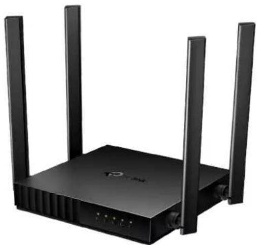
The router's LEDs (view from left to right) are located on the front. You can check the router's working status by following the LED Explanation table.
LED Explanation:
| LED Status | Indication | |
| (Power) | On Power is on. | |
| Blinking | Blinking slowly:The system is starting up or firmware upgrade is in progress.Blinking quickly:WPS connection is in progress. | |
| Off Power is off. | ||
| LED Status Indication | ||
 Wireless) Wireless) | On The 2.4GHz wireless band is enabled. | |
| Off The 2.4GHz wireless band is disabled. | ||
 Wireless) Wireless) | On The 5GHz wireless band is enabled. | |
| Off The 5GHz wireless band is disabled. | ||
 | On | At least one powered-on device is connected to the router's LAN port. |
| Off No powered-on device is connected to the router's LAN port. | ||
 | Green On | Router Mode: Internet is available.Access Point Mode: The WAN port is connected.Range Extender Mode: The router is connected to the host network. |
| Orange On The WAN port is connected, but internet is not available. | ||
| Off | Router Mode: The WAN port is not connected.Access Point Mode: The WAN port is not connected.Range Extender Mode: The router is not connected to the host network. | |
1. 2. 2. The Back Panel

The following parts (view from left to right) are located on the back panel.
Button and Port Explanation
| Item Description | |
| Power Port For connecting the router to a power socket via the provided power adapter. | |
| WAN Port For connecting to a DSL/Cable modem, or an Ethernet jack. | |
| LAN Ports (1/2/3/4) For connecting your PC or other wired devices to the router. | |
| WPS/RESET Button | Press the button for 1 second, and immediately press the WPS button on your client to start the WPS process. |
| Press and hold the button until all LEDs turn off to reset the router to its factory default settings. | |
| Antennas | Used for wireless operation and data transmit. Upright them for the best Wi-Fi performance. |
1. 2. 3. The Bottom
You can find the product label at the bottom of the router, then use the default information on it to connect to the router.

Note:
- Use the default network names (SSIDs) and password to join the networks. Or scan the QR code to join the preset 2.4 GHz network directly.
- Internet is not available until network setup is completed.
Chapter 2
Connect to the Internet
This chapter contains the following sections:
• Position Your Router - Connect to the Internet
2.1. Position Your Router
With the router, you can access your network from anywhere within the wireless network coverage. However, the wireless signal strength and coverage vary depending on the actual environment of your router. Many obstacles may limit the range of the wireless signal, for example, concrete structures or thick walls.
For your security and best Wi-Fi performance, please:
- Do NOT locate the router in a place where it will be exposed to moisture or excessive heat.
- Keep away from strong electromagnetic radiation and devices that are sensitive to electromagnetic fields.
- Place the router in a location where it can be connected to the various devices as well as to a power source.
- Make sure the cables and power cord are safely placed out of the way to avoid a tripping hazard.
Generally, the router is placed on a horizontal surface, such as on a shelf or desktop. The device can also be mounted on the wall as shown in the following figure.

Note:
The diameter of the screw should be 4.87mm < D < 10.37mm, and the distance between two screws is 80mm. The screw that projects from the wall needs to be about 4mm, and the length of the screw needs to be at least 20mm to withstand the weight of the product.
2.2. Connect to the Internet
The Router provides three working modes: Wireless Router, Range Extender, and Access Point. You can choose the mode that best suits your network needs and follow the guide to complete the configuration.
2.2.1. Wireless Router Mode
1. Follow the steps below to connect your router.
If your internet connection is through an Ethernet cable from the wall instead of through a DSL / Cable / Satellite modem, connect the Ethernet cable directly to the router's WAN port, and then follow Step 4 and 5 to complete the hardware connection.

1) Power off the modem, and remove the backup battery if it has one. 2) Connect the powered-off modem to the router's WAN port with an Ethernet cable. 3) Turn on the modem, and then wait about 2 minutes for it to restart. 4) Connect the power adapter to the router. 5) Verify that the internet LED turns solid before continuing with the configuration.
2. Connect your computer to the router.
• Method 1: Wired
Turn off the Wi-Fi on your computer and connect your computer to the router's LAN port.
• Method 2: Wireless
1) Connect your device to the router's Wi-Fi using the SSID (network name) and Wireless Password printed on the label at the bottom of the router. 2) Click the network icon of your computer or go to Wi-Fi Settings of your smart device, and then select the SSID to join the network.
Note: If you are using a smart device, you can also scan the QR code to join the preset 2.4 GHz network directly.
Smart DeviceComputer
• Method 3: Use the WPS button
Wireless devices that support WPS, including Android phones, tablets, most USB network cards, can be connected to your router through this method.
Note:
• WPS is not supported by iOS devices. - The WPS function cannot be configured if the wireless function of the router is disabled. Also, the WPS function will be disabled if your wireless encryption is WEP. Please make sure the wireless function is enabled and is configured with the appropriate encryption before configuring the WPS. 1) Tap the WPS icon on the device's screen. Here we take an Android phone as an example. 2) Immediately press the WPS button on your router.

- Enter http://tplinkwifi.net in the address bar of a web browser. Create a password to log in.
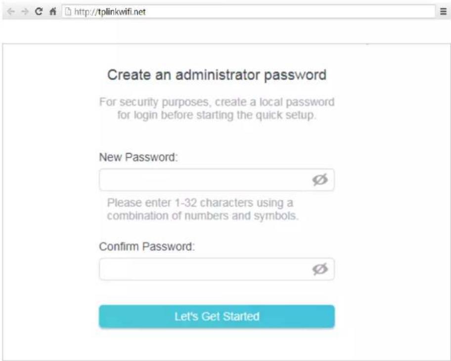
Note:
If the above screen does not pop-up, it means that your IE Web-browser has been set to a proxy. Go to menu Tools > Internet Options > Connections > LAN Settings, in the screen that appears, untick the Using Proxy checkbox, and click OK.
- Follow the Quick Setup to set up the internet connection.
- Enjoy! For wireless devices, you may have to reconnect to the wireless network if you have customized the SSID (wireless name) and password during the configuration.
2.2.2. Range Extender Mode
This mode boosts your home wireless coverage.
- Connect the power adapter to the router.
- Connect a computer to the router via an Ethernet cable or wirelessly by using the SSID (wireless name) and password printed on the bottom label of the router.
- Enter http://tplinkwifi.net in the address bar of a web browser. Create a password to log in.

Create an administrator password
For security purposes, create a local password for login before starting the quick setup.
New Password:

Please enter 1-32 characters using a combination of numbers and symbols.
Confirm Password:

Let's Get Started
- Click Change Mode in the top right corner and select Range Extender Mode. Wait for the router to reboot.
- Follow the Quick Setup to set up the internet connection.
- Relocate: Place the router between your host router and the Wi-Fi dead zone. The location you choose must be within the range of your existing host network.
![graph LR A["Router"] -->|Wireless Signal| B["WiFi"] B --> C["Extended NetworkH"] C --> D["Computer"]](/content/2026/06/1365494/images/6fe405b0f38a33466d47625872055a6933c2dac1e78cc9136f21c89306287d12.jpg)
- Enjoy! You can customize the SSID and password of the extended network.
2.2.3. Access Point Mode
This mode transforms your existing wired network to a wireless network.

- Connect the power adapter to the router.
- Connect the router to your wired host router's Ethernet port via an Ethernet cable as shown above.
- Connect a computer to the router via an Ethernet cable or wirelessly by using the SSID (network name) and password printed on the bottom label of the router.
- Enter http://tplinkwifi.net in the address bar of a web browser. Create a password to log in.

Note: If the above screen does not pop-up, it means that your IE Web-browser has been set to a proxy. Go to menu Tools > Internet Options > Connections > LAN Settings, in the screen that appears, untick the Using Proxy checkbox, and click OK.
- Click Change Mode in the top right corner and select Access Point Mode. Wait for the router to reboot.
- Follow the Quick Setup to set up the internet connection.
- Enjoy! Connect to the wireless network by using the SSID (network name) and password of the router.
Chapter 3
Log In to the Router
This chapter introduces how to log in to the web management page of the router.
With the web-based utility, it is easy to configure and manage the router. The web-based utility can be used on any Windows, Macintosh or UNIX OS with a Web browser, such as Microsoft Internet Explorer, Mozilla Firefox or Apple Safari.
Follow the steps below to log in to your router.
- Set up the TCP/IP Protocol in Obtain an IP address automatically mode on your computer.
- Visit http://tplinkwifi.net, and log in with the password you set for the router.

Note:
If the login window does not appear, please refer to the FAQ section.
Configure the Router in Wireless Router Mode
This chapter presents how to configure the various features of the router working as a wireless router.
It contains the following sections:
- Operation Mode
- Network
- Wireless
- NAT Forwarding
- Parental Controls • QoS
- Security • IPv6
- System
4.1. Operation Mode
- Visit http://tplinkwifi.net, and log in with the password you set for the router.
- Go to Advanced > Operation Mode.
- Select the working mode as needed and click SAVE.
Operation Mode
Select an operation mode according to your needs.

Router Mode (Current)
In this mode, the router can provide internet access for multiple wired and wireless devices. This mode is required most commonly.


Access Point Mode
In this mode, the router changes an existing wired network into a wireless one.


Range Extender Mode
In this mode, the router boosts the existing wireless coverage in your home.


4.2. Network
4.2.1. Status
- Visit http://tplinkwifi.net, and log in with the password you set for the router.
- Go to Advanced > Network > Status. You can view the current status information of the router.
Status
Internet status overview is displayed on this page.
Internet
Status: Connected
Internet Connection Type: Dynamic IP
IP Address: 10.0.2.224
Subnet Mask: 255.255.252.0
Default Gateway: 10.0.0.1
Primary DNS: 10.0.0.1
Secondary DNS: 0.0.0.0
LAN
MAC Address: 00-19-66-CA-8B-07
IP Address: 192.168.0.1
Subnet Mask: 255.255.255.0
DHCP Server
DHCP Server: Enabled
IP Address Pool: 192.168.0.100-192.168.0.199
Dynamic DNS
Service Provider: NO-IP
Host Name:
Status: Disconnected
- Internet - This field displays the current settings of the internet, and you can configure them on the Advanced > Network > Internet page.
- Status - Indicates whether the router has been connected to the internet.
- Internet Connection Type - Indicates the way in which your router is connected to the internet.
- IP Address - The WAN IP address of the router.
- Subnet Mask - The subnet mask associated with the WAN IP address.
- Default Gateway - The Gateway currently used is shown here. When you use Dynamic IP as the internet connection type, click Renew or Release here to obtain new IP parameters dynamically from the ISP or release them.
- Primary & Secondary DNS - The IP addresses of DNS (Domain Name System) server.
- LAN - This field displays the current settings of the LAN, and you can configure them on the Advanced > Network > LAN page.
- MAC Address - The physical address of the router.
- IP Address - The LAN IP address of the router.
- Subnet Mask - The subnet mask associated with the LAN IP address.
- DHCP Server - This field displays the current settings of DHCP (Dynamic Host Configuration Protocol) Server, and you can configure them on the Network > DHCP Server page.
- DHCP Server - Indicates whether the DHCP server is enabled or disabled. It is enabled by default and the router acts as a DHCP server.
- IP Address Pool - The IP address range for the DHCP server to assign IP addresses.
- Dynamic DNS - This field displays the current settings of the Dynamic DNS (Domain Name System), and you can configure them on the Advanced > Network > Dynamic DNS page.
- Service Provider - The Dynamic DNS service provider you have signed up for. - Host Name - The Domain Name you have entered in the Dynamic DNS page. - Status - The status of the Dynamic DNS service connection.
4.2.2. Internet
- Visit http://tplinkwifi.net, and log in with the password you set for the router.
- Go to Advanced > Network > Internet.
- Set up the internet connection and click SAVE.
Dynamic IP
If your ISP provides the DHCP service, please select Dynamic IP, and the router will automatically get IP parameters from your ISP.
Click Renew to renew the IP parameters from your ISP.
Click Release to release the IP parameters.

- MTU Size - The normal MTU (Maximum Transmission Unit) value for most Ethernet networks is 1500 Bytes. It is not recommended that you change the default MTU size unless required by your ISP.
- Host Name - This option specifies the name of the router.
- Get IP with Unicast DHCP - A few ISPs' DHCP servers do not support broadcast applications. If you cannot get the IP address normally, you can choose this option (it is rarely required).
Static IP
If your ISP provides a static or fixed IP address, subnet mask, default gateway and DNS setting, please select Static IP.

- IP Address - Enter the IP address in dotted-decimal notation provided by your ISP.
- Subnet Mask - Enter the subnet mask in dotted-decimal notation provided by your ISP. Normally 255.255.255.0 is used as the subnet mask.
- Default Gateway - Enter the gateway IP address in dotted-decimal notation provided by your ISP.
- Primary/Secondary DNS - (Optional) Enter one or two DNS addresses in dotted-decimal notation provided by your ISP.
- MTU Size - The normal MTU (Maximum Transmission Unit) value for most Ethernet networks is 1500 Bytes. It is not recommended that you change the default MTU size unless required by your ISP.
PPPoE
If your ISP provides PPPoE connection, select PPPoE.

- User Name/Password - Enter the user name and password provided by your ISP. These fields are case-sensitive.
- Secondary Connection - It's available only for PPPoE connection. If your ISP provides an extra connection type, select Dynamic IP or Static IP to activate the secondary connection.
- MTU Size - The default MTU size is 1480 bytes. It is not recommended that you change the default MTU size unless required by your ISP.
- Service Name - The service name should not be configured unless you are sure it is necessary for your ISP. In most cases, leaving these fields blank will work.
- Access Concentrator Name - The access concentrator name should not be configured unless you are sure it is necessary for your ISP. In most cases, leaving these fields blank will work.
- Detect Online Interval - The router will detect Access Concentrator online at every interval. The default value is 10. You can input the value between 0 and 120. The value 0 means no detect.
- IP Address - The default setting is to get an IP address dynamically from your ISP. If your ISP does not automatically assign IP addresses to the router, please select Use the Following IP Address and enter the IP address provided by your ISP in dotted-decimal notation.
- DNS Address - The default setting is to get an IP address dynamically from your ISP. If your ISP does not automatically assign DNS addresses to the router, please select Use the Following DNS Addresses and enter the IP address in dotted-decimal notation of your ISP's primary DNS server. If a secondary DNS server address is available, enter it as well.
- Connection Mode - Select an appropriate connection mode that determines how to connect to the internet.
- Auto - In this mode, the internet connection reconnects automatically if it gets disconnected.
- On Demand - In this mode, the internet connection will be terminated automatically after a specified inactivity period (Max Idle Time) and be re-established when you attempt to access the internet again.
- Time-based - In this mode, the internet connection is only established in a specific timeframe. If this option is selected, enter the start time and end time. Both are in HH:MM format.
- Manual - In this mode, the internet connection is controlled manually by clicking the Connect/Disconnect button. This mode also supports the Max Idle Time function as On Demand mode. Enter a maximum time (in minutes) the internet connection can be inactive before it is terminated into the Max Idle Time. The
default value is 15 minutes. If you want the internet connection to remain active all the time, enter 0 (zero).
Note:
Sometimes the connection cannot be terminated although you have specified the Max Idle Time because some applications are visiting the internet continually in the background.
L2TP
If your ISP provides L2TP connection, please select L2TP.

- Username/Password - Enter the username and password provided by your ISP. These fields are case-sensitive.
- VPN Server IP/ Domain Name - Enter the VPN server's IP address or domain name provided by your ISP.
- MTU Size - The default MTU size is "1460" bytes, which is usually fine. It is not recommended that you change the default MTU Size unless required by your ISP.
- Connection Mode
- Auto - In this mode, the internet connection reconnects automatically if it gets disconnected.
- On Demand - In this mode, the internet connection will be terminated automatically after a specified inactivity period (Max Idle Time) and be re-established when you attempt to access the internet again.
- Manual - In this mode, the internet connection is controlled manually by clicking the Connect/Disconnect button. This mode also supports the Max Idle Time function as On Demand mode. Enter a maximum time (in minutes), the internet connection can be inactive before it is terminated into the Max Idle Time. The default value is 15 minutes. If you want the internet connection remains active all the time, enter 0 (zero).
Note:
Sometimes the connection cannot be terminated although you have specified the Max Idle Time because some applications are visiting the internet continually in the background.
PPTP
If your ISP provides PPTP connection, please select PPTP.

- Username/Password - Enter the username and password provided by your ISP. These fields are case-sensitive.
- VPN Server IP/ Domain Name - Enter the VPN server's IP address or domain name provided by your ISP.
- MTU Size - The default MTU size is "1420" bytes, which is usually fine. It is not recommended that you change the default MTU Size unless required by your ISP.
- Connection Mode
- Auto - In this mode, the internet connection reconnects automatically any it gets disconnected.
- On Demand - In this mode, the internet connection will be terminated automatically after a specified inactivity period (Max Idle Time) and be re-established when you attempt to access the internet again.
- Manual - In this mode, the internet connection is controlled manually by clicking the Connect/Disconnect button. This mode also supports the Max Idle Time function as On Demand mode. Enter a maximum time (in minutes), the internet connection can be inactive before it is terminated into the Max Idle Time. The default value is 15 minutes. If you want the internet connection remains active all the time, enter 0 (zero).
Note:
Sometimes the connection cannot be terminated although you have specified the Max Idle Time because some applications are visiting the internet continually in the background.
4.2.3. MAC Clone
- Visit http://tplinkwifi.net, and log in with the password you set for the router.
- Go to Advanced > Network > Internet and locate the MAC Clone section.
- Configure the WAN MAC address and click SAVE.

- Use Default MAC Address - Do not change the default MAC address of your router in case the ISP does not bind the assigned IP address to the MAC address.
- Use Current MAC Address - Select to copy the current MAC address of the computer that is connected to the router, in case the ISP binds the assigned IP address to the MAC address.
- Use Custom MAC Address - Select if your ISP requires you to register the MAC address and enter the correct MAC address in this field, in case the ISP binds the assigned IP address to the specific MAC address.
Note:
- You can only use the MAC Address Clone function for PCs on the LAN.
- If you have changed the WAN MAC address when the WAN connection is PPPoE, it will not take effect until the connection is re-established.
4.2.4. LAN
- Visit http://tplinkwifi.net, and log in with the password you set for the router.
- Go to Advanced > Network > LAN.
- Configure the IP parameters of the LAN and click SAVE.
LAN
View and configure LAN settings.
MAC Address: 00-19-66-CA-8B-07
IP Address: 192.168.0.1
Subnet Mask: 255.255.255.0
- MAC Address - The physical address of the LAN ports. The value cannot be changed.
- IP Address - Enter the IP address in dotted-decimal notation of your router (the default one is 192.168.0.1).
- Subnet Mask - An address code that determines the size of the network. Normally 255.255.255.0 is used as the subnet mask.
Note:
- If you have changed the IP address, you must use the new IP address to log in.
- If the new IP address you set is not in the same subnet as the old one, the IP address pool in the DHCP Server will be configured automatically, but the Virtual Server and DMZ Host will not take effect until they are re-configured.
4.2.5. IPTV
- Visit http://tplinkwifi.net, and log in with the password you set for the router.
- Go to Advanced > Network > IPTV/VLAN.
- Configure the WAN MAC address and click Save.
IPTV/VLAN
Configure IPTV/VLAN settings if you want to enjoy IPTV or VoIP service, or if your ISP requires VLAN tags.
IPTV/VLAN

Enable
Mode:
Bridge
LAN1
Internet
LAN2
Internet
LAN3:
IPTV
LAN4:
IPTV
- IPTV/VLAN - Select to enable the IPTV feature.
- Mode - Select the appropriate mode according to your ISP. • LAN 1/2/3/4 - Assign your LAN port to whether function as the internet supplier or as the IPTV supplier.
4.2.6. DHCP Server
By default, the DHCP (Dynamic Host Configuration Protocol) Server is enabled and the router acts as a DHCP server; it dynamically assigns TCP/IP parameters to client devices from the IP Address Pool. You can change the settings of DHCP Server if necessary, and you can reserve LAN IP addresses for specified client devices.
• To specify the IP address that the router assigns:
- Visit http://tplinkwifi.net, and log in with the password you set for the router.
- Go to Advanced > Network > DHCP Server and locate the DHCP Server section.

- Tick the Enable checkbox.
- Enter the starting and ending IP addresses in the IP Address Pool.
- Enter other parameters if the ISP offers. The Default Gateway is automatically filled in and is the same as the LAN IP address of the router.
- Click SAVE.
Note:
To use the DHCP server function of the router, you must configure all computers on the LAN as Obtain an IP Address automatically.
• To reserve an IP address for a specified client device:
- Visit http://tplinkwifi.net, and log in with the password you set for the router.
- Go to Advanced > Network > DHCP Server and locate the Address Reservation section.
- Click Add in the Address Reservation section.

- Click VIEW CONNECTED DEVICES and select the device you want to reserve an IP for. Then the MAC and IP Address will be automatically filled in. You can also enter the MAC and IP address of the client device.

• To check the DHCP client list:
- Visit http://tplinkwifi.net, and log in with the password you set for the router.
- Go to Advanced > Network > DHCP Server and locate the DHCP Client List section. You can see the device information of the list.
- Click Refresh to see the current attached devices.
DHCP Client List
View the devices that are currently assigned with IP addresses by the DHCP server.
Total Clients: 3

Refresh
Device Name
MAC Address
Assigned IP Address
Lease Time
TP-
Link_Test_Device B0-95-8E-66-5A-03_3
192.168.0.110
01:55:42
TP-
Link_Test_Device 40-16-9F-0F-B7-BA_4
192.168.0.101
01:56:34
TP-
Link_Test_Device 54-A7-03-FE-3D-4A 5
192.168.0.102
01:56:56
4.2.7. Dynamic DNS
The router offers the DDNS (Dynamic Domain Name System) feature, which allows the hosting of a website, FTP server, or e-mail server with a fixed domain name (named by yourself) and a dynamic IP address. Thus your friends can connect to your server by entering your domain name no matter what your IP address is. Before using this feature, you need to sign up for DDNS service providers such as www.comexe.cn, www.dyndns.org, or www.noip.com. The Dynamic DNS client service provider will give you a password or key.
- Visit http://tplinkwifi.net, and log in with the username and password you set for the router.
- Go to Advanced > Network > Dynamic DNS.
- Select the DDNS Service Provider: NO-IP or DynDNS. If you don't have a DDNS account, you have to register first by clicking Register Now.
Dynamic DNS
Assign a fixed host name (domain name) for remote access to your device, website, or server behind the router.

- Enter the Username for your DDNS account.
- Enter the Password for your DDNS account.
- Enter the Domain Name you received from dynamic DNS service provider here.
- If your service provider is NO-IP, select WAN IP binding to ensure that the domain name is bound to the WAN IP of this router.
- Click LOGIN AND SAVE.
4.2.8. Static Routing
Static Routing is a form of routing that is configured manually by a network administrator or a user by adding entries into a routing table. The manually-configured routing information guides the router in forwarding data packets to the specific destination.
I want to:
Visit multiple networks and servers at the same time.
For example, in a small office, my PC can surf the internet through Router A, but I also want to visit my company's network. Now I have a switch and Router B. I connect the devices as shown in the following figure so that the physical connection between my PC and my company's server is established. To surf the internet and visit my company's network at the same time, I need to configure the static routing.
![graph TD A["INTERNET"] --> B["Router A"] B --> C["LAN: 192.168.0.1"] C --> D["Switch"] D --> E["PC"] F["Company's server"] --> G["LAN: 192.168.0.2"] G --> H["WAN: 172.30.30.100"] H --> I["172.30.30.1"] D --> J["192.168.0.100"]](/content/2026/06/1365494/images/f6218198fab68932ab740a072432373d617ec827626a60f2dae185bb7dd548ff.jpg)
How can I do that?
- Change the routers' LAN IP addresses to two different IP addresses on the same subnet. Disable Router B's DHCP function.
- Visit http://tplinkwifi.net, and log in with the password you set for Router A.
- Go to Advanced > Network > Routing and locate the Static Routing section.
- Click Add and finish the settings according to the following explanations:

- Network Destination - The destination IP address that you want to assign to a static route. This IP address cannot be on the same subnet with the WAN IP or LAN IP of Router A. In the example, the IP address of the company network is the destination IP address, so here enter 172.30.30.1.
- Subnet Mask - The Subnet Mask determines which portion of an IP address is the network portion, and which portion is the host portion.
- Default Gateway - The IP address of the gateway device to which the data packets will be sent. This IP address must be on the same subnet with the router's IP which sends out data. In the example, the data packets will be sent to the LAN port of Router B and then to the Server, so the default gateway should be 192.168.0.2.
- Interface: Determined by the port (WAN/LAN) that sends out data packets. In the example, the data are sent to the gateway through the LAN port of Router A, so LAN should be selected. • Description: Enter a description for this static routing entry.
- Click SAVE.
- Check the Routing Table below. If you can find the entry you've set, the static routing is set successfully.
4.3. Wireless
4.3.1. Wireless Settings
- Visit http://tplinkwifi.net, and log in with the password you set for the router.
- Go to Advanced > Wireless > Wireless Settings.
- Configure the wireless settings for the wireless network and click SAVE.
Wireless Settings
Personalize wireless settings as you need.

- 2.4GHz/5GHz - Select this checkbox to enable the 2.4GHz/5GHz wireless network.
- Network Name (SSID) - Enter a value of up to 32 characters. The same Name (SSID) must be assigned to all wireless devices in your network.
- Hide SSID - Select this checkbox if you want to hide the 2.4GHz network name (SSID) from the Wi-Fi network list. In this case, you need to manually join the network. • Security - Select an option from the Security drop-down list.
- None - No security. It is highly recommend you enable the wireless security to protect your wireless network from unauthorized access.
- WPA-PSK/WPA2-Personal - It's the WPA/WPA2 authentication type based on pre-shared passphrase. It's also the recommended security type. • WPA /WPA2-Enterprise - It's based on Radius Server.
- WEP - It is based on the IEEE 802.11 standard.
- Version - Keep default version value.
- Encryption - Select Auto, TKIP or AES. We recommend you keep the default settings.
- Transmit Power - Select High, Middle or Low to specify the data transmit power. The default and recommended setting is High.
- Channel Width - Select a channel width (bandwidth) for the wireless network.
- Channel - Select an operating channel for the wireless network. It is recommended to leave the channel to Auto. It is not necessary to change the wireless channel unless you notice interference problems with another nearby access point.
- Mode - You can choose the appropriate "Mixed" mode.
4.3.2. Guest Network
Guest Network allows you to provide Wi-Fi access for guests without disclosing your host network. When you have guests in your house, apartment, or workplace, you can create a guest network for them. In addition, you can customize guest network settings to ensure network security and privacy.
- Visit http://tplinkwifi.net, and log in with the password you set for the router.
- Go to Wireless or Advanced > Wireless > Guest Network.
- Enable the Guest Network function.

- Create a network name for your guest network.
- Select the Security type and create the Password of the guest network.
- Click SAVE. Now your guests can access your guest network using the SSID and password you set!
- Customize Guest Network Options
- Visit http://tplinkwifi.net, and log in with the password you set for the router.
- Go to Advanced > Wireless > Guest Network. Locate the Guest Permissions section.
- Customize guest network options according to your needs.

- Allow guests to see each other
Tick this checkbox if you want to allow the wireless clients on your guest network to communicate with each other via methods such as network neighbors and Ping.
- Allow guests to access my local network
Tick this checkbox if you want to allow the wireless clients on your guest network to communicate with the devices connected to your router's LAN ports or main network via methods such as network neighbors and Ping.
- Click SAVE. Now you can ensure network security and privacy!
4.3.3. Wireless Schedule
The wireless function can be automatically off at a specific time when you do not need the wireless function.
- Visit http://tplinkwifi.net, and log in with the password you set for the router.
- Go to Advanced > Wireless > Wireless Schedule.
- Enable the Wireless Schedule function.

- Click Add to specify a wireless off period during which you need the wireless off automatically, and click SAVE.

Note:
- The effective wireless schedule is based on the time of the router. You can go to Advanced > System > Time to modify the time. The wireless network will be automatically turned on after the time period you set.
4.3.4 WPS
WPS (Wi-Fi Protected Setup) can help you to quickly and securely connect to a network. This section will guide you to add a new wireless device to your router's network quickly via WPS.
Note:
The WPS function cannot be configured if the wireless function of the router is disabled. Please make sure the wireless function is enabled before configuration.
- Visit http://tplinkwifi.net, and log in with the password you set for the router.
- Go to Advanced > Wireless > WPS.
- Follow one of the following three methods to connect your client device to the router's Wi-Fi network.
Method 1: Using a PIN
- Connects via the Client's PIN
- Keep the WPS Status as Enabled and select Client's PIN.

- Enter the PIN of your device and click CONNECT. Then your device will get connected to the router.
- Connects via the Router's PIN
- Keep the WPS Status as Enabled and select Router's PIN.

- Enter the PIN on your personal device. You can use the default PIN or generate a new one.
Note:
PIN (Personal Identification Number) is an eight-character identification number preset to each router. WPS supported devices can connect to your router with the PIN. The default PIN is printed on the label of your router.
Method 2: Using the device's WPS button
Click Start on the screen. Within two minutes, press the WPS button on your device. A Device-(XX-XX-XX-XX-XX-XX) Connected message should appear on the screen and the LED should change from blinking to solid on, indicating successful WPS connection.
Note:
XX-XX-XX-XX-XX-XX is the MAC address of your device.

Method 3: Using the router's WPS button
Press the router's WPS button, then enable WPS on your personal device within 2 minutes.
4. 3. 5. Additional Wireless Settings
- Visit http://tplinkwifi.net, and log in with the password you set for the router.
- Go to Advanced > Wireless > Additional Settings.
- Configure the advanced settings of your wireless network and click Save.
Note:
If you are not familiar with the setting items on this page, it's strongly recommended to keep the provided default values; otherwise it may result in lower wireless network performance.

- Enable WMM - WMM function can guarantee that packets with high-priority messages are transmitted preferentially. It is strongly recommended to enable this function.
- Enable Short GI - It is recommended to enable this function, as it will increase data capacity by reducing the guard interval time.
- AP Isolation - This function isolates all connected wireless stations so that they cannot access each other through the WLAN.
- Beacon Interval - Enter a value between 40-1000 milliseconds for the Beacon Interval here. The Beacon Interval value determines the time interval of the beacons. The beacons are the packets sent by the router to synchronize a wireless network. The default value is 100.
- RTS Threshold - Here you can specify the RTS (Request to Send) Threshold. If the packet is larger than the specified RTS Threshold size, the router will send RTS frames to a particular receiving station and negotiate the sending of a data frame. The default value is 2346.
- DTIM Interval - This value determines the interval of the Delivery Traffic Indication Message (DTIM). A DTIM field is a countdown field informing clients of the next window for listening to broadcast and multicast messages. When the router has buffered broadcast or multicast messages for associated clients, it sends the next DTIM with a DTIM Interval value. You can specify a value between 1-255 Beacon Intervals. The default value is 1, which indicates that the DTIM Interval is the same as the Beacon Interval.
- Group Key Update Period - Enter a number of seconds (minimum 30) to control the time interval for the automatic renewal of the encryption key. The default value is 0, meaning no key renewal.
4.4. NAT Forwarding
The router's NAT (Network Address Translation) feature allows devices on the LAN to use the same public IP address to communicate on the internet, which protects the local network by hiding the IP addresses of the devices. However, it also brings about the problem that external hosts cannot initiate communication with specified devices in the local network.
With the forwarding feature, the router can traverse the isolation of NAT so that clients on the internet can reach devices on the LAN and realize some specific functions.
The TP-Link router includes four forwarding rules. If two or more rules are set, the priority of implementation from high to low is Port Forwarding, Port Triggering, UPnP, and DMZ.
4.4.1. Port Forwarding
When you build a server in the local network and want to share it on the internet, Port Forwarding can realize the service and provide it to internet users. At the same time, Port Forwarding can keep the local network safe as other services are still invisible from the internet.
Port Forwarding can be used to set up public services in your local network, such as HTTP, FTP, DNS, POP3/SMTP and Telnet. Different services use different service ports. Port 80 is used for HTTP service, port 21 for FTP service, port 25 for SMTP service, and port 110 for POP3 service. Please verify the service port number before configuration.
I want to:
Share my personal website I've built in the local network with my friends through the internet.
For example, the personal website has been built on my home PC (192.168.0.100). I hope that my friends on the internet can visit my website in some way. My PC is connected to the router with the WAN IP address 218.18.232.154.
![graph LR A["Personal Website"] --> B["Router"] B --> C["INTERNET"] C --> D["Computer"] style A fill:#f9f,stroke:#333 style B fill:#ccf,stroke:#333 style C fill:#cfc,stroke:#333 style D fill:#fcc,stroke:#333](/content/2026/06/1365494/images/c5b108f323ff476d60c625b9fe10a76cbd7e5800c957c58371cf2fcc11cb1890.jpg)
- Set your PC to a static IP address, for example 192.168.0.100.
- Visit http://tplinkwifi.net, and log in with the password you set for the router.
- Go to Advanced > NAT Forwarding > Port Forwarding.
- Click Add.

- Click VIEW COMMON SERVICES and select HTTP. The External Port, Internal Port, and Protocol will be automatically filled in.
- Click VIEW CONNECTED DEVICES and select your home PC. The Device IP Address will be automatically filled in. Or enter the PC's IP address 192.168.0.100 manually in the Device IP Address field.
7. Click SAVE.
Note:
- It is recommended to keep the default settings of Internal Port and Protocol if you are not clear about which port and protocol to use.
- If the service you want to use is not in the Common Services list, you can enter the corresponding parameters manually. You should verify the port number that the service needs.
- You can add multiple virtual server rules if you want to provide several services on a router. Please note that the External Port should not be overlapped.
Done!
Users on the internet can enter http:// WAN IP (in this example: http:// 218.18.232.154) to visit your personal website.
Note:
- If you have changed the default External Port, you should use http:// WAN IP: External Port to visit the website.
- The WAN IP should be a public IP address. For the WAN IP is assigned dynamically by the ISP, it is recommended to apply and register a domain name for the WAN referring to Dynamic DNS. Then users on the internet can use http://domain name to visit the website.
4. 4. 2. Port Triggering
Port triggering can specify a triggering port and its corresponding external ports. When a host in the local network initiates a connection to the triggering port, all the external ports will be opened for subsequent connections. The router can record the IP address of the host. When the data from the internet return to the external ports, the router can forward them to the corresponding host. Port triggering is mainly applied to online games, VoIPs, video players and common applications including MSN Gaming Zone, Dialpad, Quick Time 4 players and more.
Follow the steps below to configure the port triggering rules:
- Visit http://tplinkwifi.net, and log in with the password you set for the router.
- Go to Advanced > NAT Forwarding > Port Triggering.
- Click Add.
- Click VIEW COMMON SERVICES, and select the desired application. The Triggering Port, Triggering Protocol and External Port will be automatically filled in. The following picture takes application MSN Gaming Zone as an example.

5. Click SAVE.
Note:
- You can add multiple port triggering rules as needed. • The triggering ports can not be overlapped.
- If the application you need is not listed in the Common Services list, please enter the parameters manually. You should verify the external ports the application uses first and enter them in the External Ports field. You can input at most 5 groups of ports (or port sections). Every group of ports must be set apart with a comma. For example, 2000-2038, 2050-2051, 2085, 3010-3030.
4.4.3 UPnP
The UPnP (Universal Plug and Play) protocol allows applications or host devices to automatically find the front-end NAT device and send requests to it to open the corresponding ports. With UPnP enabled, applications or host devices on the local network and the internet can freely communicate with each other, realizing the seamless connection of the network. You may need to enable UPnP if you want to use applications for multiplayer gaming, peer-to-peer connections, real-time communication (such as VoIP or telephone conference), or remote assistance, etc.
Tips:
- UPnP is enabled by default in this router.
- Only applications supporting the UPnP protocol can use this feature.
- UPnP feature needs the support of the operating system (e.g., Windows Vista/Windows 7/Windows 8, etc. Some operating systems need to install the UPnP components).
For example, when you connect your Xbox to the router which is connected to the internet to play online games, UPnP will send a request to the router to open the corresponding ports, allowing the following data to penetrate the NAT to transmit. Therefore, you can play Xbox online games without a hitch.
![graph LR A["Game Controller"] -->|LAN| B["RouterXbox"] B -->|WAN| C["INTERNET"] B --> D["Internet"]](/content/2026/06/1365494/images/96eb1835e00115b51cc3ee85b33ada9a3fd99a699ecf07a09bd41ae9b40c07b7.jpg)
If necessary, you can follow the steps to change the status of UPnP.
- Visit http://tplinkwifi.net, and log in with the password you set for the router.
- Go to Advanced > NAT Forwarding > UPnP and toggle on or off according to your needs.
UPnP
Enable UPnP (Universal Plug and Play) to allow devices on your local network to dynamically open ports for applications such as multiplayer gaming and real-time communications.
UPnP

4.4.4 DMZ
When a PC is set to be a DMZ (Demilitarized Zone) host in the local network, it is totally exposed to the internet, which can realize the unlimited bidirectional communication
between internal hosts and external hosts. The DMZ host becomes a virtual server with all ports opened. When you are not clear about which ports to open in some special applications, such as IP camera and database software, you can set the PC to be a DMZ host.
Note: DMZ is more applicable in the situation that users are not clear about which ports to open. When it is enabled, the DMZ host is totally exposed to the internet, which may bring some potential safety hazards. If DMZ is not in use, please disable it in time.
I want to:
Make the home PC join the internet online game without port restriction.
For example, due to some port restriction, when playing the online games, you can log in normally but cannot join a team with other players. To solve this problem, set your PC as a DMZ host with all ports opened.
How can I do that?
- Assign a static IP address to your PC, for example 192.168.0.100.
- Visit http://tplinkwifi.net, and log in with the password you set for the router.
- Go to Advanced > NAT Forwarding > DMZ and select Enable.
- Click VIEW CONNECTED DEVICES and select your PC. The DMZ Host IP Address will be automatically filled in. Or enter the PC's IP address manually in the DMZ Host IP Address field.

5. Click SAVE.
Done!
You've set your PC to a DMZ host and now you can make a team to game with other players.
4.5. Parental Controls
Parental Controls allows you to set up unique restrictions on internet access for each member of your family. You can block inappropriate content, set daily limits for the total time spent online and restrict internet access to certain times of the day.
I want to:
Block access to inappropriate online content for my child's devices, restrict internet access to 2 hours every day and block internet access during bed time (10 PM to 7 AM) on weekdays.
How can I do that?
- Visit http://tplinkwifi.net, and log in with the password you set for the router.
- Go to Advanced > Parental Controls.
- Click Add to create a profile for a family member.

- Add basic profile information.
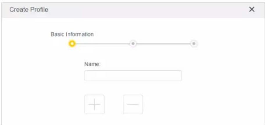
1) Enter a Name for the profile to make it easier to identify. 2) Under Devices, click +. 3) Select the devices that belong to this family member. Access restrictions will be applied to these devices. Click ADD when finished.
Note: Only devices that have previously been connected to your router's network are listed here. If you are unable to find the device you want to add, connect it to your network and then try again.
4) Click NEXT.
- Block content for this profile.

1) Enter the key word of the website that you want to block. Click if want to block multiple websites. 2) Click NEXT.
- Set time restrictions on internet access.

1) Enable Time Limits on Monday to Friday and Saturday & Sunday, then set the allowed online time to 2 hours each day. 2) Enable Bed Time on School Nights and use the up/down arrows or enter times in the fields. Devices under this profile will be unable to access the internet during this time period. 3) Click SAVE.
Note: The effective time limits are based on the time of the router. You can go to Advanced > System > Time to modify the time.
Done!
The amount of time your child spends online is controlled and inappropriate content is blocked on their devices.
4.6. QoS
QoS (Quality of Service) is designed to ensure the efficient operation of the network when it comes across network overload or congestion. Devices set as high priority will be allocated more bandwidth and so continue to run smoothly even when there are many devices connected to the network.
I want to:
Ensure a fast connection of my computer while I play online games for the next 2 hours.
How can I do that?
- Visit http://tplinkwifi.net, and log in with the password you set for the router.
- Go to Advanced > QoS.
- Tick the Enable checkbox of QoS.
- Enter the maximum upload and download bandwidths provided by your internet service provider, and then click SAVE. 1Mbps equals to 1,000Kbps.
- Find your computer in the Device Priority section and toggle on Priority. Select 2 hours from the drop-down list of Timing. Your computer will be prioritized for the next 2 hours.

Done!
You can now enjoy playing games without lag on your computer for the next 2 hours.
4.7. Security
This function allows you to protect your home network from cyber attacks and unauthorized users by implementing these network security functions.
4.7.1. Firewall
The SPI (Stateful Packet Inspection) Firewall protects the router from cyber attacks and validates the traffic that is passing through the router based on the protocol. This function is enabled by default.
- Visit http://tplinkwifi.net, and log in with the password you set for the router.
- Go to Advanced > Security > Firewall, and configure the parameters as you need. It's recommended to keep the default settings.
4.7.2. Access Control
Access Control is used to block or allow specific client devices to access your network (via wired or wireless) based on a list of blocked devices (Blacklist) or a list of allowed devices (Whitelist).
I want to:
Block or allow specific client devices to access my network (via wired or wireless).
How can I do that?
- Visit http://tplinkwifi.net, and log in with the password you set for the router.
- Go to Advanced > Security > Access Control:
- Select the access mode to either block (recommended) or allow the device(s) in the list.
To block specific device(s):
1) Select Blacklist and click SAVE.

2) Click Add and select devices you want to block. You can see the devices have been added to the blacklist.

To allow specific device(s):
1) Select Whitelist and click SAVE

2) Add devices to the whitelist.
- Add connected devices
Click Select From Device List and select the devices you want to be allowed.

- Add unconnected devices
Click Add Manually and enter the Device Name and MAC Address of the device you want to be allowed.

Done!
Now you can block or allow specific client devices to access your network (via wired or wireless) using the Blacklist or Whitelist.
4.7.3. IP & MAC Binding
IP & MAC Binding, namely ARP (Address Resolution Protocol) Binding, is used to bind a network device's IP address to its MAC address. This prevents ARP Spoofing and other ARP attacks by denying network access to a device with a matching IP address in the Binding list but an unrecognized MAC address.
I want to:
Prevent ARP spoofing and ARP attacks.
How can I do that?
- Visit http://tplinkwifi.net, and log in with the password you set for the router.
- Go to Advanced > Security > IP & MAC Binding.
- Enable IP & MAC Binding and click SAVE.
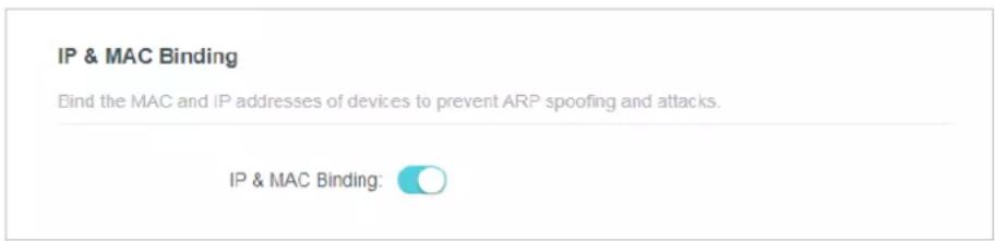
- Bind your device(s) according to your need.
To bind the connected device(s):
Locate the ARP List section and enable Bind to bind the IP and MAC addresses of a specific device.

To add a binding entry:
1) Click Add in the Binding List section.
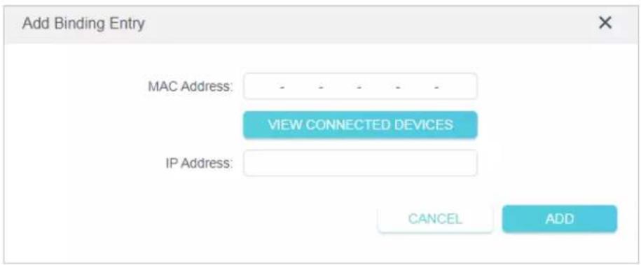
2) Click VIEW CONNECTED DEVICES and select the device you want to bind. Or enter the MAC Address and IP Address that you want to bind. 3) Click ADD.
4.8. ALG (Application Layer Gateway)
View your ALG (Application Layer Gateway) settings on this page. It is recommended to keep them as default.

4.9. IPv6
This function allows you to enable IPv6 and set up the parameters of the router's Wide Area Network (WAN) and Local Area Network (LAN).
4.9.1. IPv6 Status
- Visit http://tplinkwifi.net, and log in with the password you set for the router.
- Go to Advanced > IPv6, and you can view the current IPv6 status information of the router.
- Enable IPv6 and select the mode: Router or Pass-Through (Bridge).
- If you select Router:

Fill in WAN and LAN information as required by different connection types.
1. Normal: The default connection type.
1) Configure the WAN settings.

2) Configure the LAN settings. Fill in the Address Prefix provided by your ISP.

3) Click SAVE.
- PPPoE: Select this type if your ISP uses PPPoEv6, and provides a username and password.
1) Configure the WAN settings.
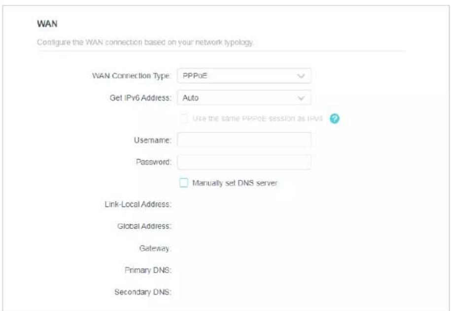
2) Configure the LAN settings. Fill in the Address Prefix provided by your ISP.

- Tunnel 6to4: Select this type if your ISP uses 6to4 deployment for assigning addresses.
1) Configure the WAN settings.

2) Configure the LAN settings.

- If you select Pass-Through (Bridge):
Click SAVE. No configuration is required.

4.10 System
4.10.1 Firmware Upgrade
TP-Link is dedicated to improving and enriching the product features, giving users a better network experience. We will release the latest firmware at TP-Link official website
www.tp-link.com. You can download the latest firmware file from the Support page of our website and upgrade the firmware to the latest version.
- Download the latest firmware file for the router from our website www.tp-link.com.
- Visit http://tplinkwifi.net, and log in with the password you set for the router.
- Go to Advanced > System > Firmware Upgrade.
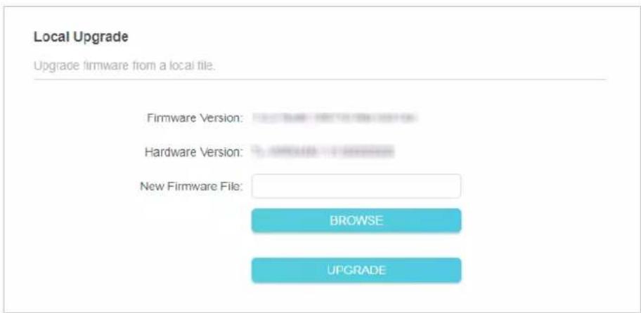
- Click BROWSE to locate the downloaded firmware file, and click UPGRADE.
4.10.2 Backup & Restore
The configuration settings are stored as a configuration file in the router. You can backup the configuration file in your computer for future use and restore the router to the previous settings from the backup file when needed.
- Visit http://tplinkwifi.net, and log in with the password you set for the router.
- Go to Advanced > System > Backup & Restore.
- To backup configuration settings:
Click BACK UP to save a copy of the current settings in your local computer. A ".bin" file of the current settings will be stored in your computer.

• To restore configuration settings:
- Click BROWSE to locate the backup configuration file stored in your computer, and click RESTORE.
- Wait a few minutes for the restoring and rebooting.

- To reset the router to factory default settings:
- Click FACTORY RESTORE to reset the router.

2. Wait a few minutes for the restoring and rebooting.
Note:
- During the resetting process, do not turn off or reset the router.
- We strongly recommend you backup the current configuration settings before resetting the router.
4. 10. 3. Change Password
- Visit http://tplinkwifi.net, and log in with the password you set for the router.
- Go to Advanced > System > Administration, and focus on the Change Password section.

- Enter the old password, then a new password twice (both case-sensitive). Click SAVE.
- Use the new password for future logins.
4. 10. 4. Local Management
- Visit http://tplinkwifi.net, and log in with the password you set for the router.
- Go to Advanced > System > Administration, and focus on the Local Management section.
- Allow all LAN connected devices to manage the router:
Select All Devices for Local Managers.

- Allow specific devices to manage the router:
- Select Specified Devices for Local Managers and click SAVE.

2. Click Add Device.

- Click VIEW CONNECTED DEVICES and select the device to manage the router from the Connected Devices list, or enter the MAC address of the device manually.
- Specify a Description for this entry.
- Click SAVE.
4.10.5 Remote Management
- Visit http://tplinkwifi.net, and log in with the password you set for the router.
- Go to Advanced > System > Administration, and focus on the Remote Management section.
Note:
If your ISP assigns a private WAN IP address (such as 192.168.x.x or 10.x.x.x), you cannot use this feature because private addresses are not routable.
- Forbid all devices to manage the router remotely:
Do not tick the Enable checkbox of Remote Management.

- Allow all devices to manage the router remotely:
Remote Management
Access and manage the router over the internet.
Note: Remote Management is not supported when you are connected to the internet only via IPv6. If you want to use Remote Management, please make sure you have set up an IPv4 connection first.
Remote Management:
Enable
HTTP Port
8888
Web Address for Management:
10.0.2.225
Remote Managers:
All Devices

- Tick the Enable checkbox of Remote Management.
- Keep the HTTP port as default setting (recommended) or enter a value between 1024 and 65535.
- Select All Devices for Remote Managers.
- Click SAVE.
Devices on the internet can log in to http://Router's WAN IP address: port number (such as http://113.116.60.229:1024) to manage the router.
Tips:
• You can find the WAN IP address of the router on Network Map > Internet. - The router's WAN IP is usually a dynamic IP. Please refer to Dynamic DNS if you want to log in to the router through a domain name. - Allow a specific device to manage the router remotely:
Remote Management
Access and manage the router over the internet.
Note: Remote Management is not supported when you are connected to the internet only via IPv6. If you want to use Remote Management, please make sure you have set up an IPv4 connection first.
Remote Management
Enable
HTTP Port
8888
Web Address for Management
10 0 2 225
Remote Managers.
Specified Device
Only this IP Address:

- Tick the Enable checkbox of Remote Management.
- Keep the HTTP port as default setting (recommended) or enter a value between 1024 and 65535.
- Select Specified Device for Remote Managers.
- In the Only this IP Address field, enter the IP address of the remote device to manage the router.
- Click SAVE.
Devices using this WAN IP can manage the router by logging in to http://Router's WAN IP:port number (such as http://113.116.60.229:1024).
Tips: The router's WAN IP is usually a dynamic IP. Please refer to Dynamic DNS if you want to log in to the router through a domain name.
4. 10. 6. System Log
- Visit http://tplinkwifi.net, and log in with the password you set for the router.
- Go to Advanced > System > System Log, and you can view the logs of the router.
![System Log View a detailed record of system activities. Current Time: 19/11/2019 19:44:20 Search Refresh Clear All 1 EXCEPTION exception message 2 WARNING 0days, 00:00:01, [lan]Invalid lan mac, now start by default mac 00-19-66-CA-8B-07. 3 INFO 0days, 00:00:01, [lan]LAN: Attach mirror0 to stack. 4 I…](/content/2026/06/1365494/images/28a0c546c247d4f66e5d6ef530ce34b83197b50ac024d04cbdf586456c305d29.jpg)
- Click SAVE TO LOCAL to save the system logs to a local disk.
4. 10. 7. Diagnostic
Diagnostic is used to test the connectivity between the router and the host or other network devices.
- Visit http://tplinkwifi.net, and log in with the password you set for the router.
2. Go to Advanced > System > Diagnostics.

3. Enter the information:
1) Choose Ping or Tracert as the diagnostic tool to test the connectivity;
- Ping is used to test the connectivity between the router and the tested host, and measure the round-trip time.
- Tracert is used to display the route (path) your router has passed to reach the tested host, and measure transit delays of packets across an Internet Protocol network. 2) Enter the IP Address or Domain Name of the tested host. 3) Modify the Ping Count number and the Ping Packet Size. It's recommended to keep the default value. 4) If you have chosen Tracert, you can modify the Traceroute Max TTL. It's recommended to keep the default value.
4. Click START to begin the diagnostics.
The figure below indicates the proper connection between the router and the Yahoo server (www.Yahoo.com) tested through Ping.
![Finding host yahoo.com by DNS server (1 of 2). Pinging yahoo.com [98.138.219.231] with 64 bytes of data: Reply from 98.138.219.231: bytes=64 time=233ms TTL=48 (seq=0). Reply from 98.138.219.231: bytes=64 time=233ms TTL=48 (seq=1). Reply from 98.138.219.231: bytes=64 time=233ms TTL=48 (seq=2). Reply…](/content/2026/06/1365494/images/5fff549e514c0b2c14f10bdff62dee5a02bec2d5dddaed275ad1662a06e526c5.jpg)
The figure below indicates the proper connection between the router and the Yahoo server (www.Yahoo.com) tested through Tracert.
![Finding host yahoo.com by DNS server (1 of 2). Tracing route to yahoo.com [72.30.35.10] over a maximum of 20 hops: 1 1 ms 1 ms 1 ms 10.0.0.1, 2 1 ms 1 ms 1 ms 116.24.64.1, 3 1 ms 1 ms 1 ms 202.105.155.185, 4 1 ms 1 ms 1 ms 183.56.65.2, 5 * 1 ms * 202.97.94.150, 6 16 ms 16 ms 16 ms 202.97.94.94, 7 15…](/content/2026/06/1365494/images/1f969e3d378423c6eccb938d7e917f5651b947c78d60e1f3ca6bc143dfd67872.jpg)
4. 10.8. Time Settings
This page allows you to set the time manually or to configure automatic time synchronization. The router can automatically update the time from an NTP server via the internet.
- Visit http://tplinkwifi.net, and log in with the password you set for the router.
- Go to Advanced > System > Time.
- To set System Time:

- Select the way in which the router gets its time: Get from Internet, Get from Managing Device, Manually.
- Select your local Time Zone.
- Enter the address or domain of the NTP Server 1 or NTP Server 2.
- Click SAVE.
• To set up Daylight Saving Time:
- Select Enable Daylight Saving.
Daylight Saving Time
Automatically synchronize the system time with daylight saving time.
Daylight Saving Time:

Enable
Running Status: Daylight Saving Time is off.
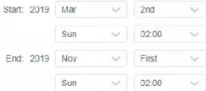
- Select the start time from the drop-down list in the Start fields.
- Select the end time from the drop-down list in the End fields.
- Click SAVE.
Note:
This setting will be used for some time-based functions such as firewall. You must specify your time zone once you log in to the router successfully; otherwise, time-based functions will not take effect.
4. 10. 9. Reboot
Some settings of the router will take effect only after rebooting, and the system will reboot automatically. You can also reboot the router to clear cache and enhance running performance.
- Visit http://tplinkwifi.net, and log in with the password you set for the router.
- Go to Advanced > System > Reboot, and you can restart your router.
• To reboot the router manually:
Click REBOOT, and wait a few minutes for the router to reboot.

• To set the router to reboot regularly:
- Tick the Enable box of Reboot Schedule.
- Specify the Reboot Time when the router reboots and Repeat to decide how often it reboots.
3. Click SAVE.

4. 10. 10. LED Control
The LED of the router indicates its activities and status. You can enable the Night Mode feature to specify a time period during which the LED is off.
- Visit http://tplinkwifi.net, and log in with the password you set for the router.
- Go to Advanced > System > LED Control.
- Enable Night Mode.

- Specify the LED off time, and the LED will be off during this period every day.
Note: The effective LED off time is based on the time of the router. You can go to Advanced > System > Time & Language to modify the time.
- Click SAVE.
Configure the Router in Access Point Mode
This chapter presents how to configure the various features of the router working as an access point.
It contains the following sections:
- Operation Mode
- Firmware Upgrade
- Backup & Restore
- Administration
- System Log
- Diagnostic
- Time Settings
- Reboot
- LED Control
5.1. Operation Mode
- Visit http://tplinkwifi.net, and log in with the password you set for the router.
- Go to System > Operation Mode.
- Select the working mode as needed and click SAVE.
Operation Mode
Select an operation mode according to your needs.

Router Mode (Current)
In this mode, the router can provide internet access for multiple wired and wireless devices. This mode is required most commonly.


Access Point Mode
In this mode, the router changes an existing wired network into a wireless one.


Range Extender Mode
In this mode, the router boosts the existing wireless coverage in your home.


5.2. Firmware Upgrade
TP-Link is dedicated to improving and enriching the product features, giving users a better network experience. We will release the latest firmware at TP-Link official website www.tp-link.com. You can download the latest firmware file from the Support page of our website and upgrade the firmware to the latest version.
- Download the latest firmware file for the router from our website www.tp-link.com.
- Visit http://tplinkwifi.net, and log in with the password you set for the router.
- Go to System > Firmware Upgrade.
- Click BROWSE to locate the downloaded firmware file, and click UPGRADE.

The configuration settings are stored as a configuration file in the router. You can backup the configuration file in your computer for future use and restore the router to the previous settings from the backup file when needed.
- Visit http://tplinkwifi.net, and log in with the password you set for the router.
- Go to System > Backup & Restore.
- To backup configuration settings:
Click BACK UP to save a copy of the current settings in your local computer. A ".bin" file of the current settings will be stored in your computer.

• To restore configuration settings:
- Click BROWSE to locate the backup configuration file stored in your computer, and click RESTORE.
- Wait a few minutes for the restoring and rebooting.

- To reset the router to factory default settings:
- Click FACTORY RESTORE to reset the router.
- Wait a few minutes for the restoring and rebooting.
Note:
- During the resetting process, do not turn off or reset the router. • We strongly recommend you backup the current configuration settings before resetting the router.
5.4. Administration
5.4.1. Change Password
- Visit http://tplinkwifi.net, and log in with the password you set for the router.
- Go to System > Administration, and focus on the Change Password section.
Change Password
Change the router's local management password.
Old Password
......
∅
New Password
∅
Confirm New Password
∅
- Enter the old password, then a new password twice (both case-sensitive). Click SAVE.
- Use the new password for future logins.
5.4.2. Local Management
- Visit http://tplinkwifi.net, and log in with the password you set for the router.
- Go to System > Administration, and focus on the Local Management section.
- Allow all LAN connected devices to manage the router:
Select All Devices for Local Managers.
Local Management
Access and manage the router from local network devices.
Local Managers
All Devices
√
- Allow specific devices to manage the router:
- Select Specified Devices for Local Managers and click SAVE.

- Click Add Device.

- Click VIEW CONNECTED DEVICES and select the device to manage the router from the Connected Devices list, or enter the MAC address of the device manually.
- Specify a Description for this entry.
- Click SAVE.
5.5. System Log
- Visit http://tplinkwifi.net, and log in with the password you set for the router.
- Go to System > System Log, and you can view the logs of the router.
![System Log. View a detailed record of system activities. Current Time: 19/11/2019 19:44:20. Search. Refresh. Clear All. 1 EXCEPTION exception message. 2 WARNING 0days, 00:00:01, [lan]Invalid lan mac, now start by default mac 00-19-66-CA-8B-07. 3 INFO 0days, 00:00:01, [lan]LAN: Attach mirror0 to stac…](/content/2026/06/1365494/images/71c66f6321da2925993b5751a88ede295962301a35110d05a1930287fe8b556d.jpg)
- Click SAVE TO LOCAL to save the system logs to a local disk.
5.6. Diagnostic
Diagnostic is used to test the connectivity between the router and the host or other network devices.
- Visit http://tplinkwifi.net, and log in with the password you set for the router.
- Go to System > Diagnostics.

- Enter the information:
1) Choose Ping or Tracert as the diagnostic tool to test the connectivity; - Ping is used to test the connectivity between the router and the tested host, and measure the round-trip time.
- Tracert is used to display the route (path) your router has passed to reach the tested host, and measure transit delays of packets across an Internet Protocol network. 2) Enter the IP Address or Domain Name of the tested host. 3) Modify the Ping Count number and the Ping Packet Size. It's recommended to keep the default value. 4) If you have chosen Tracert, you can modify the Traceroute Max TTL. It's recommended to keep the default value.
4. Click START to begin the diagnostics.
The figure below indicates the proper connection between the router and the Yahoo server (www.Yahoo.com) tested through Ping.
Finding host yahoo.com by DNS server (1 of 2).
Pinging yahoo.com [98.138.219.231] with 64 bytes of data:
Reply from 98.138.219.231: bytes=64 time=233ms TTL=48 (seq=0).
Reply from 98.138.219.231: bytes=64 time=233ms TTL=48 (seq=1).
Reply from 98.138.219.231: bytes=64 time=233ms TTL=48 (seq=2).
Reply from 98.138.219.231: bytes=64 time=233ms TTL=48 (seq=3).
Ping statistics for 98.138.219.231:
Packets: Sent = 4, Received = 4, Lost = 0 (0% loss).
Approximate round trip times in milli-seconds:
Minimum = 233ms, Maximum = 233ms, Average = 233ms
The figure below indicates the proper connection between the router and the Yahoo server (www.Yahoo.com) tested through Tracert.
Finding host yahoo.com by DNS server (1 of 2).
Tracing route to yahoo.com [72.30.35.10]
over a maximum of 20 hops:
1 1 ms 1 ms 1 ms 10.0.0.1
2 1 ms 1 ms 1 ms 116.24.64.1
3 1 ms 1 ms 1 ms 202.105.155.185
4 1 ms 1 ms 1 ms 183.56.65.2
5 * 1 ms * 202.97.94.150
6 16 ms 16 ms 16 ms 202.97.94.94
7 150 ms 150 ms 150 ms 202.97.27.242
8 166 ms 166 ms 166 ms 202.97.50.74
9 150 ms 150 ms 150 ms 4.53.210.145
5.7. Time Settings
This page allows you to set the time manually or to configure automatic time synchronization. The router can automatically update the time from an NTP server via the internet.
- Visit http://tplinkwifi.net, and log in with the password you set for the router.
- Go to System > Time.
- To set System Time:

- Select the way in which the router gets its time: Get from Internet, Get from Managing Device, Manually.
- Select your local Time Zone.
- Enter the address or domain of the NTP Server 1 or NTP Server 2.
- Click SAVE.
• To set up Daylight Saving Time:
1. Select Enable Daylight Saving.

- Select the start time from the drop-down list in the Start fields.
- Select the end time from the drop-down list in the End fields.
- Click SAVE.
Note:
This setting will be used for some time-based functions such as firewall. You must specify your time zone once you log in to the router successfully; otherwise, time-based functions will not take effect.
5.8. Reboot
Some settings of the router will take effect only after rebooting, and the system will reboot automatically. You can also reboot the router to clear cache and enhance running performance.
- Visit http://tplinkwifi.net, and log in with the password you set for the router.
- Go to System > Reboot, and you can restart your router.
• To reboot the router manually:
Click REBOOT, and wait a few minutes for the router to reboot.

- To set the router to reboot regularly:
- Tick the Enable box of Reboot Schedule.
- Specify the Reboot Time when the router reboots and Repeat to decide how often it reboots.
- Click SAVE.
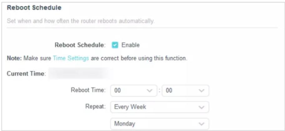
5.9. LED Control
The LED of the router indicates its activities and status. You can enable the Night Mode feature to specify a time period during which the LED is off.
- Visit http://tplinkwifi.net, and log in with the password you set for the router.
- Go to System > LED Control.
- Enable Night Mode.

- Specify the LED off time, and the LED will be off during this period every day.
Note: The effective LED off time is based on the time of the router. You can go to Advanced > System > Time & Language to modify the time.
- Click SAVE.
Configure the Router in Range Extender Mode
This chapter presents how to configure the various features of the router working as a range extender.
It contains the following sections:
- Operation Mode
- Firmware Upgrade
- Backup & Restore
- Administration
- System Log
- Time Settings
- Reboot
- LED Control
6. 1. Operation Mode
- Visit http://tplinkwifi.net, and log in with the password you set for the router.
- Go to System > Operation Mode.
- Select the working mode as needed and click SAVE.
Operation Mode
Select an operation mode according to your needs.
Router Mode (Current)
In this mode, the router can provide internet access for multiple wired and wireless devices. This mode is required most commonly.
![graph LR A[" globe "] --> B[" router "] B --> C[" mobile"]](/content/2026/06/1365494/images/a7c93cc0bf2bc29891cef951265d8a36e930b7c55cd4891c95fc3dbc276ff1e0.jpg)
Access Point Mode
In this mode, the router changes an existing wired network into a wireless one.
![graph LR A["Internet LAN"] --> B["Mobile Phone"] C["Internet LAN"] --> D["Mobile Phone"] style A fill:#f9f,stroke:#333 style B fill:#ccf,stroke:#333 style C fill:#cfc,stroke:#333 style D fill:#fcc,stroke:#333](/content/2026/06/1365494/images/ff65b1d94481109d0cf8be821d4a1a2f72092c8c6325377cbaedc74d11adfed2.jpg)
Range Extender Mode
In this mode, the router boosts the existing wireless coverage in your home.
![graph LR A[" globe "] --> B[" Internet LAN "] B --> C[" LAN "] C --> D[" wireless device "] D --> E[" mobile phone "]](/content/2026/06/1365494/images/930d0d8584de5e1e62b5fe97fc3c655fb46bb5237e9f1783e1e032d1979ddd22.jpg)
6.2. Firmware Upgrade
TP-Link is dedicated to improving and enriching the product features, giving users a better network experience. We will release the latest firmware at TP-Link official website www.tp-link.com. You can download the latest firmware file from the Support page of our website and upgrade the firmware to the latest version.
- Download the latest firmware file for the router from our website www.tp-link.com.
- Visit http://tplinkwifi.net, and log in with the password you set for the router.
- Go to System > Firmware Upgrade.
- Click BROWSE to locate the downloaded firmware file, and click UPGRADE.

The configuration settings are stored as a configuration file in the router. You can backup the configuration file in your computer for future use and restore the router to the previous settings from the backup file when needed.
- Visit http://tplinkwifi.net, and log in with the password you set for the router.
- Go to System > Backup & Restore.
- To backup configuration settings:
Click BACK UP to save a copy of the current settings in your local computer. A ".bin" file of the current settings will be stored in your computer.

• To restore configuration settings:
- Click BROWSE to locate the backup configuration file stored in your computer, and click RESTORE.
- Wait a few minutes for the restoring and rebooting.

- To reset the router to factory default settings:
- Click FACTORY RESTORE to reset the router.
- Wait a few minutes for the restoring and rebooting.
Note:
- During the resetting process, do not turn off or reset the router. • We strongly recommend you backup the current configuration settings before resetting the router.
6.4. Administration
6.4.1. Change Password
- Visit http://tplinkwifi.net, and log in with the password you set for the router.
- Go to System > Administration, and focus on the Change Password section.
Change Password
Change the router's local management password.
Old Password
......
∅
New Password
∅
Confirm New Password
- Enter the old password, then a new password twice (both case-sensitive). Click SAVE.
- Use the new password for future logins.
6.4.2. Local Management
- Visit http://tplinkwifi.net, and log in with the password you set for the router.
- Go to System > Administration, and focus on the Local Management section.
- Allow all LAN connected devices to manage the router:
Select All Devices for Local Managers.
Local Management
Access and manage the router from local network devices.
Local Managers
All Devices
V
- Allow specific devices to manage the router:
1. Select Specified Devices for Local Managers and click SAVE.

2. Click Add Device.

- Click VIEW CONNECTED DEVICES and select the device to manage the router from the Connected Devices list, or enter the MAC address of the device manually.
- Specify a Description for this entry.
- Click SAVE.
6.5. System Log
- Visit http://tplinkwifi.net, and log in with the password you set for the router.
- Go to System > System Log, and you can view the logs of the router.
![System Log View a detailed record of system activities. Current Time: 19/11/2019 19:44:20 Search Refresh Clear All 1 EXCEPTION exception message 2 WARNING 0days, 00:00:01, [lan]Invalid lan mac, now start by default mac 00-19-66- CA-8B-07. 3 INFO 0days, 00:00:01, [lan]LAN: Attach mirror0 to stack. 4…](/content/2026/06/1365494/images/4580ca03aabb366e671741ffa5cfea968da12f537778728fd300c97ee5b9222e.jpg)
- Click SAVE TO LOCAL to save the system logs to a local disk.
6.6. Time Settings
This page allows you to set the time manually or to configure automatic time synchronization. The router can automatically update the time from an NTP server via the internet.
- Visit http://tplinkwifi.net, and log in with the password you set for the router.
- Go to System > Time.
• To set System Time:

- Select the way in which the router gets its time: Get from Internet, Get from Managing Device, Manually.
- Select your local Time Zone.
- Enter the address or domain of the NTP Server 1 or NTP Server 2.
- Click SAVE.
• To set up Daylight Saving Time:
- Select Enable Daylight Saving.

- Select the start time from the drop-down list in the Start fields.
- Select the end time from the drop-down list in the End fields.
- Click SAVE.
Note:
This setting will be used for some time-based functions such as firewall. You must specify your time zone once you log in to the router successfully; otherwise, time-based functions will not take effect.
6.7. Reboot
Some settings of the router will take effect only after rebooting, and the system will reboot automatically. You can also reboot the router to clear cache and enhance running performance.
- Visit http://tplinkwifi.net, and log in with the password you set for the router.
- Go to System > Reboot, and you can restart your router.
To reboot the router manually:
Click REBOOT, and wait a few minutes for the router to reboot.

To set the router to reboot regularly:
- Tick the Enable box of Reboot Schedule.
- Specify the Reboot Time when the router reboots and Repeat to decide how often it reboots.
- Click SAVE.

6.8. LED Control
The LED of the router indicates its activities and status. You can enable the Night Mode feature to specify a time period during which the LED is off.
- Visit http://tplinkwifi.net, and log in with the password you set for the router.
- Go to System > LED Control.
- Enable Night Mode.
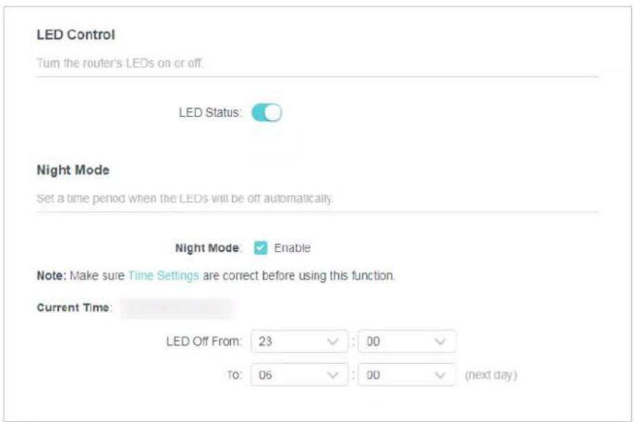
- Specify the LED off time, and the LED will be off during this period every day.
Note: The effective LED off time is based on the time of the router. You can go to Advanced > System > Time & Language to modify the time.
- Click SAVE.
FAQ
Q1. What should I do if I forget my wireless password?
The default wireless password is printed on the label of the router. If the password has been altered, please connect your computer to the router using an Ethernet cable and follow the steps below:
- Visit http://tplinkwifi.net, and log in with the password you set for the router.
- Go to Wireless or Advanced > Wireless > Wireless Settings to retrieve or reset your wireless password.
Q2. What should I do if I forget my login password of the web management page?
- Reset the router to its factory default settings.
- Visit http://tplinkwifi.net, and create a password for future login.
Note: You'll need to reconfigure the router to surf the Internet once the router is reset, and please mark down your new password for future use.
Q3. What should I do if I cannot log in to the router's web management page?
This can happen for a variety of reasons. Please try the methods below to log in again.
- Make sure your computer has connected to the router correctly and the corresponding LED light up.
- Make sure the IP address of your computer is configured as Obtain an IP address automatically and Obtain DNS server address automatically.
- Make sure you enter the correct IP address to log in: http://tplinkwifi.net or 192.168.0.1.
- Check your computer's settings:
1) Go to Start > Control Panel > Network and Internet, and click View network status and tasks. 2) Click Internet Options on the bottom left. 3) Click Connections and select Never dial a connection.

4) Click LAN settings and deselect the following three options, and click OK.

5) Go to Advanced > Restore advanced settings, and click OK.

- Use another web browser or computer to log in again.
- Reset the router to factory default settings and try again. If the login still fails, please contact technical support.
Note: You'll need to reconfigure the router to surf the internet once the router is reset.
Q4. What should I do if I cannot access the internet even though the configuration is finished?
- Visit http://tplinkwifi.net, and log in with the password you set for the router.
- Go to Advanced > Network > Status to check the Internet status:
If IP Address is a valid one, please try the methods below and try again:
- Your computer might not recognize any DNS server addresses, please manually configure DNS server.
1) Go to Advanced > Network > DHCP Server. 2) Enter 8.8.8.8 as Primary DNS, and click Save.
Tips: 8.8.8.8 is a safe and public DNS server operated by Google.

- Restart the modem and the router.
1) Power off your modem and the router, and leave them off for 1 minute. 2) Power on your modem first, and wait about 2 minutes. 3) Power on the router, and wait another 1 or 2 minutes and check the Internet access.
- Reset the router to factory default settings and reconfigure the router.
- Upgrade the firmware of the router.
- Check the TCP/IP settings on the particular device if all other devices can get internet from the router.
If the IP Address is 0.0.0.0, please try the methods below and try again:
- Make sure the physical connection between the router and the modem is proper.
- Clone the MAC address of your computer.
1) Visit http://tplinkwifi.net, and log in with the username and password you set for the router. 2) Go to Advanced > Network > Internet, select Clone Current Device MAC and click SAVE.

Tips:
- Some ISPs will register the MAC address of your computer when you access the Internet for the first time through their Cable modem. If you add a router to your network to share your Internet connection, the ISP will not accept it because the MAC address has changed. So we need to clone your computer's MAC address to the router.
- The MAC addresses of a computer in wired connection and wireless connection are different.
- Modify the LAN IP address of the router.
Note:
Most TP-Link routers use 192.168.0.1/192.168.1.1 as their default LAN IP address. It may conflict with the IP range of your existing ADSL modem/router. If so, the router is not able to communicate with your modem and you can't access the Internet. To resolve this problem, we need to change the LAN IP address of the router to avoid such conflict, for example, 192.168.2.1.
1) Visit http://tplinkwifi.net, and log in with the username and password you set for the router. 2) Go to Advanced > Network > LAN. 3) Modify the LAN IP address as the following picture shows. Here we take 192.168.2.1 as an example. 4) Click Save.

- Restart the modem and the router.
1) Power off your modem and the router, and leave them off for 1 minute. 2) Power on your modem first, and wait about 2 minutes. 3) Power on the router, and wait another 1 or 2 minutes and check the internet access.
- Double check the Internet Connection Type.
1) Confirm your Internet Connection Type, which can be learned from the ISP. 2) Visit http://tplinkwifi.net, and log in with the username and password you set for the router. 3) Go to Advanced > Network > WAN. 4) Select your Internet Connection Type and fill in other parameters. 5) Click SAVE.

6) Restart the modem and the router.
- Please upgrade the firmware of the router.
If you've tried every method above but cannot access the internet, please contact the technical support.
Q5. What should I do if I cannot find my wireless network or I cannot connect to the wireless network?
If you fail to find any wireless network, please follow the steps below:
- Make sure the wireless function of your device is enabled if you're using a laptop with a built-in wireless adapter. You can refer to the relevant document or contact the laptop manufacturer.
- Make sure the wireless adapter driver is installed successfully and the wireless adapter is enabled.
- On Windows 7
1) If you see the message No connections are available, it is usually because the wireless function is disabled or blocked somehow.
2) Clicking Troubleshoot and windows might be able to fix the problem by itself.
- On Windows XP
1) If you see the message Windows cannot configure this wireless connection, this is usually because windows configuration utility is disabled or you are running another wireless configuration tool to connect the wireless. 2) Exit the wireless configuration tool (the TP-Link Utility, for example). 3) Select and right click My Computer on Desktop, and select Manage to open Computer Management window. 4) Expand Services and Applications > Services, and find and locate Wireless Zero Configuration in the Services list on the right side. 5) Right click Wireless Zero Configuration, and then select Properties. 6) Change Startup type to Automatic, click Start and make sure the Service status is Started. And then click OK.
If you can find other wireless networks except your own, please follow the steps below:
- Make sure your computer/device is still in the range of your router/modem. Move closer if it is currently too far away.
If you can find your wireless network but fail to connect, please follow the steps below:
- Authenticating problem/password mismatch:
1) Sometimes you will be asked to type in a PIN number when you connect to the wireless network for the first time. This PIN number is different from the Wireless Password/Network Security Key. Usually you can only find it on the label of your router.
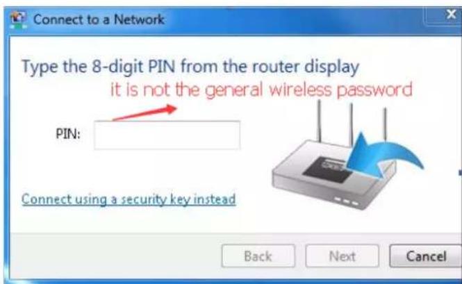
2) If you cannot find the PIN or PIN failed, you may choose Connecting using a security key instead, and then type in the Wireless Password/Network Security Key. 3) If it continues to show note of Network Security Key Mismatch, it is suggested to confirm the wireless password of your wireless router.
Note: Wireless Password/Network Security Key is case sensitive.
- Windows unable to connect to XXXX / Can not join this network / Taking longer than usual to connect to this network:
- Check the wireless signal strength of your network, if it is weak (1~3 bars), please move the router closer and try again.
- Change the wireless Channel of the router to 1, 6, or 11 to reduce interference from other networks.
- Re-install or update the driver for your wireless adapter of the computer.
COPYRIGHT & TRADEMARKS
Specifications are subject to change without notice. 📋 is a registered trademark of TP-Link Technologies Co., Ltd. Other brands and product names are trademarks or registered trademarks of their respective holders.
No part of the specifications may be reproduced in any form or by any means or used to make any derivative such as translation, transformation, or adaptation without permission from TP-Link Technologies Co., Ltd. Copyright © 2020 TP-Link Technologies Co., Ltd. All rights reserved.
FCC compliance information statement

Product Name: AC1200 Dual Band Wi-Fi Router
Model Number: Archer C54
Component Name Model
I.T.E. Power T090085-2B1
Responsible party:
TP-Link USA Corporation, d/b/a TP-Link North America, Inc.
Address: 145 South State College Blvd. Suite 400, Brea, CA 92821
Website: http://www.tp-link.com/us/
Tel: +1 626 333 0234
This equipment has been tested and found to comply with the limits for a Class B digital device, pursuant to part 15 of the FCC Rules. These limits are designed to provide reasonable protection against harmful interference in a residential installation. This equipment generates, uses and can radiate radio frequency energy and, if not installed and used in accordance with the instructions, may cause harmful interference to radio communications. However, there is no guarantee that interference will not occur in a particular installation. If this equipment does cause harmful interference to radio or television reception, which can be determined by turning the equipment off and on, the user is encouraged to try to correct the interference by one or more of the following measures:
- Reorient or relocate the receiving antenna.
- Increase the separation between the equipment and receiver.
- Connect the equipment into an outlet on a circuit different from that to which the receiver is connected.
- Consult the dealer or an experienced radio/ TV technician for help.
This device complies with part 15 of the FCC Rules. Operation is subject to the following two conditions:
- This device may not cause harmful interference.
- This device must accept any interference received, including interference that may cause undesired operation.
Any changes or modifications not expressly approved by the party responsible for compliance could void the user's authority to operate the equipment.
Note: The manufacturer is not responsible for any radio or TV interference caused by unauthorized modifications to this equipment. Such modifications could void the user's authority to operate the equipment.
FCC RF Radiation Exposure Statement
This equipment complies with FCC RF radiation exposure limits set forth for an uncontrolled environment. This device and its antenna must not be co-located or operating in conjunction with any other antenna or transmitter.
"To comply with FCC RF exposure compliance requirements, this grant is applicable to only Mobile Configurations. The antennas used for this transmitter must be installed to provide a separation distance of at least 20 cm from all persons and must not be co-located or operating in conjunction with any other antenna or transmitter."
We, TP-Link USA Corporation, have determined that the equipment shown above complies with the applicable technical standards, FCC Part 15. No unauthorized changes have been made to the equipment, and the equipment is properly maintained and operated.
Issue Date: 2020-06-28
FCC compliance information statement
Product Name: I.T.E. Power Supply
Model Number: T090085-2B1
Responsible party:
TP-Link USA Corporation, d/b/a TP-Link North America, Inc.
Address: 145 South State College Blvd. Suite 400, Brea, CA 92821
Website: http://www.tp-link.com/us/
Tel: +1 626 333 0234
This equipment has been tested and found to comply with the limits for a Class B digital device, pursuant to part 15 of the FCC Rules. These limits are designed to provide reasonable protection against harmful interference in a residential installation. This equipment generates, uses and can radiate radio frequency energy and, if not installed and used in accordance with the instructions, may cause harmful interference to radio communications. However, there is no guarantee that interference will not occur in a particular installation. If this equipment does cause harmful interference to radio or television reception, which can be determined by turning the equipment off and on, the user is encouraged to try to correct the interference by one or more of the following measures:
- Reorient or relocate the receiving antenna.
- Increase the separation between the equipment and receiver.
- Connect the equipment into an outlet on a circuit different from that to which the receiver is connected.
- Consult the dealer or an experienced radio/TV technician for help.
This device complies with part 15 of the FCC Rules. Operation is subject to the following two conditions:
- This device may not cause harmful interference.
- This device must accept any interference received, including interference that may cause undesired operation.
Any changes or modifications not expressly approved by the party responsible for compliance could void the user's authority to operate the equipment.
We, TP-Link USA Corporation, have determined that the equipment shown above complies with the applicable technical standards, FCC part 15. No unauthorized change has been made to the equipment, and the equipment is properly maintained and operated.
Issue Date: 2020-06-28
CE Mark Warning
CE
This is a class B product. In a domestic environment, this product may cause radio interference, in which case the user may be required to take adequate measures.
OPERATING FREQUENCY (the maximum transmitted power)
2400 MHz -2483.5 MHz (20dBm)
5150 MHz -5250 MHz(23dBm)
EU Declaration of Conformity
TP-Link hereby declares that the device is in compliance with the essential requirements and other relevant provisions of directives 2014/53/EU, 2009/125/EC, 2011/65/EU and (EU)2015/863.
The original EU declaration of conformity may be found at https://www.tp-link.com/en/ce
RF Exposure Information
This device meets the EU requirements (2014/53/EU Article 3.1a) on the limitation of exposure of the general public to electromagnetic fields by way of health protection.
The device complies with RF specifications when the device used at 20 cm from your body.
Industry Canada Statement
CAN ICES-3 (B)/NMB-3(B)
Korea Warning Statements:
National Restrictions
Attention: This device may only be used indoors in all EU member states and EFTA countries.
 | AT | BE | BG | CH | CY | CZ | DE | DK | ||
| EE | EL | ES | FI | FR | HR | HI | UE | |||
| IS | IT | LI | LT | LU | L | VMT | NL | |||
| NO | PL | PT | RO | SE | SI | SK | UK | |||
Canadian Compliance Statement
This device contains licence-exempt transmitter(s)/receiver(s) that comply with Innovation, Science and Economic Development Canada's licence-exempt RSS(s). Operation is subject to the following two conditions:
(1) This device may not cause interference.
(2) This device must accept any interference, including interference that may cause undesired operation of the device.
- The device for operation in the band 5150–5250 MHz is only for indoor use to reduce the potential for harmful interference to co-channel mobile satellite systems.
Warning:
Radiation Exposure Statement:
This equipment complies with IC radiation exposure limits set forth for an uncontrolled environment. This equipment should be installed and operated with minimum distance 20cm between the radiator & your body.
| 設備名稱: AC1200 Dual Band Wi-Fi Router Equipment name | 型號(型式): Archer C54Type designation (Type) | |||||
| 單元Unit | 限用物質及其化學符號Restricted substances and its chemical symbols | |||||
| 鉛Lead(Pb) | 汞Mercury(Hg) | 鎘 Cadmium(Cd) | 六價鉻Hexavalent chromium( Cr+6 ) | 多溴聯苯Polybrominated biphenyls(PBB) | 多溴二苯醚Polybrominated diphenyl ethers(PBDE) | |
| PCB○○○○○ | ||||||
| 外殼 | ○○○ | ○○○ | ||||
| 電源供應器 | —○○ | ○○○ | ||||
| 天線 | ○○○ | ○○○ | ||||
| 備考 1. “超出 0.1 wt %” 及 “超出 0.01 wt %” 係指限用物質之百分比含量超出百分比含量基準值Note 1: "Exceeding 0.1 wt %" and "exceeding 0.01 wt %" indicate that the percentage content of the restricted substance exceeds the reference percentage value of presence condition.備考 2. “o” 係指該項限用物質之百分比含量未超出百分比含量基準值。Note 2: "o" indicates that the percentage content of the restricted substance does not exceed the percentage of reference value of presence.備考 3. “—” 係指該項限用物質為排除項目。Note 3: The “-” indicates that the restricted substance corresponds to the exemption. | ||||||

- Keep the device away from water, fire, humidity or hot environments.
- Do not attempt to disassemble, repair, or modify the device. If you need service, please contact us.
- Do not use damaged charger or USB cable to charge the device.
- Do not use any other chargers than those recommended.
- Do not use the device where wireless devices are not allowed.
- Adapter shall be installed near the equipment and shall be easily accessible.
- Use only power supplies which are provided by manufacturer and in the original packing of this product. If you have any questions, please don't hesitate to contact us.
Please read and follow the above safety information when operating the device. We cannot guarantee that no accidents or damage will occur due to improper use of the device. Please use this product with care and operate at your own risk.
Explanations of the symbols on the product label
| Symbol Explanation | |
 | Alternating current |
 | DC voltage |
 | Class II equipment |
 | Polarity of d.c. power connector |
| [c7ZZ] | Energy efficiency Marking |
 | Indoor use only |
 | Operator's manual |
 | RECYCLINGThis product bears the selective sorting symbol for Waste electrical and electronic equipment (WEEE). This means that this product must be handled pursuant to European directive 2012/19/EU in order to be recycled or dismantled to minimize its impact on the environment.User has the choice to give his product to a competent recycling organization or to the retailer when he buys a new electrical or electronic equipment. |

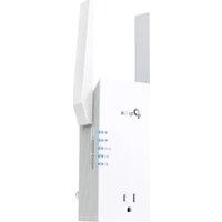
- CHAPTER 1. GET TO KNOW ABOUT YOUR ROUTER
- CHAPTER 2. CONNECT TO THE INTERNET
- CHAPTER 3. LOG IN TO THE ROUTER
- CHAPTER 4. CONFIGURE THE ROUTER IN WIRELESS ROUTER MODE
- CHAPTER 5. CONFIGURE THE ROUTER IN ACCESS POINT MODE
- CHAPTER 6. CONFIGURE THE ROUTER IN RANGE EXTENDER MODE
- ABOUT THIS GUIDE
- CONVENTIONS
- MORE INFO
- CHAPTER
- GET TO KNOW ABOUT YOUR ROUTER
- PRODUCT OVERVIEW
- APPEARANCE
- TOP PANEL
- LED EXPLANATION
- THE BACK PANEL
- BUTTON AND PORT EXPLANATION
- THE BOTTOM
- NOTE
- CONNECT TO THE INTERNET
- POSITION YOUR ROUTER
- WIRELESS ROUTER MODE
- FOLLOW THE STEPS BELOW TO CONNECT YOUR ROUTER
- CONNECT YOUR COMPUTER TO THE ROUTER
- METHOD 2: WIRELESS
- METHOD 3: USE THE WPS BUTTON
- RANGE EXTENDER MODE
- CREATE AN ADMINISTRATOR PASSWORD
- ACCESS POINT MODE
- LOG IN TO THE ROUTER
- CONFIGURE THE ROUTER IN WIRELESS ROUTER MODE
- OPERATION MODE
- ROUTER MODE (CURRENT)
- NETWORK
- STATUS
- INTERNET
- LAN
- DHCP SERVER
- DYNAMIC DNS
- DYNAMIC IP
- STATIC IP
- PPPOE
- L2TP
- PPTP
- MAC CLONE
- IPTV
- IPTV/VLAN
- TO SPECIFY THE IP ADDRESS THAT THE ROUTER ASSIGNS
- DHCP CLIENT LIST
- STATIC ROUTING
- I WANT TO
- HOW CAN I DO THAT
- WIRELESS
- WIRELESS SETTINGS
- GUEST NETWORK
- CUSTOMIZE GUEST NETWORK OPTIONS
- WIRELESS SCHEDULE
- WPS
- METHOD 1: USING A PIN
- CONNECTS VIA THE CLIENT'S PIN
- CONNECTS VIA THE ROUTER'S PIN
- METHOD 2: USING THE DEVICE'S WPS BUTTON
- METHOD 3: USING THE ROUTER'S WPS BUTTON
- ADDITIONAL WIRELESS SETTINGS
- NAT FORWARDING
- PORT FORWARDING
- CLICK SAVE
- DONE
- PORT TRIGGERING
- UPNP
- TIPS
- DMZ
- PARENTAL CONTROLS
- QOS
- SECURITY
- FIREWALL
- ACCESS CONTROL
- TO BLOCK SPECIFIC DEVICE(S)
- TO ALLOW SPECIFIC DEVICE(S)
- IP & MAC BINDING
- ALG (APPLICATION LAYER GATEWAY)
- IPV
- IPV6 STATUS
- IF YOU SELECT ROUTER
- NORMAL: THE DEFAULT CONNECTION TYPE
- CONFIGURE THE WAN SETTINGS
- CONFIGURE THE LAN SETTINGS. FILL IN THE ADDRESS PREFIX PROVIDED BY YOUR ISP
- SYSTEM
- FIRMWARE UPGRADE
- BACKUP & RESTORE
- TO BACKUP CONFIGURATION SETTINGS
- TO RESTORE CONFIGURATION SETTINGS
- TO RESET THE ROUTER TO FACTORY DEFAULT SETTINGS
- WAIT A FEW MINUTES FOR THE RESTORING AND REBOOTING
- CHANGE PASSWORD
- LOCAL MANAGEMENT
- CLICK ADD DEVICE
- REMOTE MANAGEMENT
- SYSTEM LOG
- DIAGNOSTIC
- GO TO ADVANCED > SYSTEM > DIAGNOSTICS
- ENTER THE INFORMATION
- CLICK START TO BEGIN THE DIAGNOSTICS
- TIME SETTINGS
- DAYLIGHT SAVING TIME
- REBOOT
- TO REBOOT THE ROUTER MANUALLY
- TO SET THE ROUTER TO REBOOT REGULARLY
- LED CONTROL
- CONFIGURE THE ROUTER IN ACCESS POINT MODE
- ADMINISTRATION
- ALLOW SPECIFIC DEVICES TO MANAGE THE ROUTER
- TO SET SYSTEM TIME
- TO SET UP DAYLIGHT SAVING TIME
- SELECT ENABLE DAYLIGHT SAVING
- CONFIGURE THE ROUTER IN RANGE EXTENDER MODE
- SELECT SPECIFIED DEVICES FOR LOCAL MANAGERS AND CLICK SAVE
- FAQ
- Q1. WHAT SHOULD I DO IF I FORGET MY WIRELESS PASSWORD
- Q2. WHAT SHOULD I DO IF I FORGET MY LOGIN PASSWORD OF THE WEB MANAGEMENT PAGE
- Q3. WHAT SHOULD I DO IF I CANNOT LOG IN TO THE ROUTER'S WEB MANAGEMENT PAGE
- Q4. WHAT SHOULD I DO IF I CANNOT ACCESS THE INTERNET EVEN THOUGH THE CONFIGURATION IS FINISHED
- Q5. WHAT SHOULD I DO IF I CANNOT FIND MY WIRELESS NETWORK OR I CANNOT CONNECT TO THE WIRELESS NETWORK
- COPYRIGHT & TRADEMARKS
- FCC COMPLIANCE INFORMATION STATEMENT
- RESPONSIBLE PARTY
- FCC RF RADIATION EXPOSURE STATEMENT
- CE MARK WARNING
- CE
- OPERATING FREQUENCY (THE MAXIMUM TRANSMITTED POWER)
- EU DECLARATION OF CONFORMITY
- RF EXPOSURE INFORMATION
- INDUSTRY CANADA STATEMENT
- KOREA WARNING STATEMENTS
- NATIONAL RESTRICTIONS
- CANADIAN COMPLIANCE STATEMENT
- WARNING
- RADIATION EXPOSURE STATEMENT
Brand : TP-LINK
Model : Archer C54
Category : Wi-Fi repeater