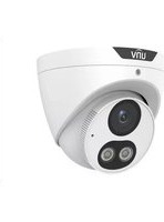
IPC3615SE-ADF28KM-WL-I0 - Surveillance Camera UniView - Free user manual and instructions
Find the device manual for free IPC3615SE-ADF28KM-WL-I0 UniView in PDF.


| Product Type | Surveillance Camera (IP) |
| Brand | UniView |
| Model | IPC3615SE-ADF28KM-WL-I0 |
| Resolution | 2 Megapixels (1920×1080) |
| Lens | 2.8mm fixed lens |
| Night Vision | Up to 30m IR range |
| Power Supply | DC 12V or PoE (802.3af) |
| Power Consumption | ≤ 5W |
| Dimensions (W×H×D) | 70 × 70 × 150 mm |
| Weight | 0.5 kg |
| Weatherproof Rating | IP67 |
| Operating Temperature | -30°C to 60°C |
| Video Compression | H.265+/H.265/H.264 |
| Motion Detection | Yes |
| Audio | Built-in microphone |
| Memory Slot | MicroSD card up to 128GB |
| Network Interface | 10/100 Mbps Ethernet |
| Mounting Type | Ceiling or wall mount |
| Cleaning | Wipe with a soft, dry cloth. Avoid harsh chemicals. |
| Safety | Supports HTTPS encryption and password protection. |
| Spare Parts | Available through UniView authorized dealers. |
| Warranty | 2 years |
| Included Accessories | Mounting kit, power adapter |
Frequently Asked Questions - IPC3615SE-ADF28KM-WL-I0 UniView
User questions about IPC3615SE-ADF28KM-WL-I0 UniView
0 question about this device. Answer the ones you know or ask your own.
Ask a new question about this device
Download the instructions for your Surveillance Camera in PDF format for free! Find your manual IPC3615SE-ADF28KM-WL-I0 - UniView and take your electronic device back in hand. On this page are published all the documents necessary for the use of your device. IPC3615SE-ADF28KM-WL-I0 by UniView.
USER MANUAL IPC3615SE-ADF28KM-WL-I0 UniView
Network Camera User Manual
Manual Version: V3.06
Thank you for your purchase. If you have any questions, please do not hesitate to contact your dealer.
Disclaimer
No part of this manual may be copied, reproduced, translated or distributed in any form or by any means without prior consent in writing from Zhejiang Uniview Technologies Co., Ltd (hereinafter referred to as Uniview or us).
The content in the manual is subject to change without prior notice due to product version upgrades or other reasons.
This manual is for reference only, and all statements, information, and recommendations in this manual are presented without warranty of any kind.
To the extent allowed by applicable law, in no event will Uniview be liable for any special, incidental, indirect, consequential damages, nor for any loss of profits, data, and documents.
Safety Instructions

CAUTION!
The default password is intended only for your first login. For security, we strongly recommend you set a strong password of at least 9 characters comprising digits, letters, and special characters.
Be sure to read this manual carefully before use and strictly comply with this manual during operation.
The illustrations in this manual are for reference only and may vary depending on the version or model. The screenshots in this manual may have been customized to meet specific requirements and user preferences. As a result, some of the examples and functions featured may differ from those displayed on your monitor.
- This manual is intended for multiple product models, and the photos, illustrations, descriptions, etc., in this manual may be different from the actual appearances, functions, features, etc., of the product.
- The mouse operations described in this manual are right-handed operations.
- Uniview reserves the right to change any information in this manual without any prior notice or indication.
- Due to uncertainties such as physical environment, discrepancy may exist between the actual values and reference values provided in this manual. The ultimate right to interpretation resides in our company.
- Users are fully responsible for the damages and losses that arise due to improper operations.
Environmental Protection
This product has been designed to comply with the requirements on environmental protection. For the proper storage, use and disposal of this product, national laws and regulations must be observed.
Safety Symbols
The symbols in the following table may be found in this manual. Carefully follow the instructions indicated by the symbols to avoid hazardous situations and use the product properly.
| Symbol | Description |
 WARNING! WARNING! | Indicates a hazardous situation which, if not avoided, could result in bodily injury or death. |
 CAUTION! CAUTION! | Indicates a situation which, if not avoided, could result in damage, data loss or malfunction to product. |
 NOTE! NOTE! | Indicates useful or supplemental information about the use of product. |
Contents
Disclaimer ...... i
Safety Instructions ...... i
Environmental Protection....i
Safety Symbols ...... i
1 Login 1
1.1 Preparation 1
1.2 Login 1
1.3 Global Search 3
2 Live View 3
2.1 Live View 3
2.1.1 Pixel Calculation 6
2.1.2 Digital Zoom 7
2.1.3 Capture 7
2.1.4 5ePTZ 8
2.2 PTZ Control 8
2.2.1 3D Positioning 9
2.2.2 Area Focus 10
2.2.3 Preset 10
2.2.4 Patrol 11
2.3 General Parameters 20
3 Playback....21
3.1 Playback Toolbar 21
3.2 Search and Playback 22
3.3 Recording Download 22
4 Photo 24
5 Setup 25
5.1 Local Parameters ...... 25
5.2 Network 27
5.2.1 Basic Config 27
5.2.2 Service Configuration 35
5.2.3 Platform Access 40
5.3 Video & Audio 47
5.3.1 Video 47
5.3.2 Snapshot 49
5.3.3 Audio 50
5.3.4 ROI....52
5.3.5 View Cropping....53
5.3.6 Media Stream 54
5.4 PTZ 55
5.4.1 Basic PTZ Settings....55
5.4.2 Auto Guard 56
5.4.3 Pan/Tilt Limit 57
5.4.4 Preset Snapshot and Patrol Resumption 58
5.4.5 Orientation 58
5.5 Image 59
5.5.1 Image....59
5.5.2 OSD 74
5.5.3 Privacy Mask 76
5.5.4 Quick Focus 77
5.6 Smart....78
5.6.1 Alarm-triggered Actions 79
5.6.2 Arming Schedule 81
5.6.3 Smart Service Switch 82
5.6.4 Cross Line Detection 84
5.6.5 Enter Area Detection 85
5.6.6 Leave Area Detection 87
5.6.7 Intrusion Detection 88
5.6.8 Object Removed Detection 90
5.6.9 Object Left Behind Detection 91
5.6.10 Defocus Detection 93
5.6.11 Scene Change Detection 93
5.6.12 Face Detection 93
5.6.13 Face Recognition 98
5.6.14 Human Body Detection 101
5.6.15 Multi-Target Detection 102
5.6.16 Traffic Monitoring /ANPR 106
5.6.17 Heat Map 112
5.6.18 People Flow Counting 114
5.6.19 Crowd Density Monitoring 116
5.6.20 Auto Tracking 118
5.6.21 Smoke and Fire Detection 118
5.6.22 Metadata Collection 122
5.6.23 Advanced Settings 123
5.6.24 Panoramic Linkage 124
5.7 Alarm 129
5.7.1 Thermal Imaging Alarm 129
5.7.2 Common Alarm 133
5.7.3 One-key Disarming 142
5.8 Storage 143
5.8.1 Memory Card 143
5.8.2 Network Disk 145
5.8.3 FTP 146
5.9 Security 148
5.9.1 User 148
5.9.2 HTTPS 151
5.9.3 Authentication 151
5.9.4 Registration Information 152
5.9.5 ARP Protection....152
5.9.6 IP Address Filtering 153
5.9.7 MAC Address Filtering 153
5.9.8 Access Policy....154
5.9.9 Certificate Management 155
5.9.10 Watermark 158
5.10 System 159
5.10.1 Time.... 159
5.10.2 DST 160
5.10.3 Device Information 160
5.10.4 Ports & External Devices 161
5.10.5 Maintenance 166
5.10.6 Logs 168
5.10.7 System 169
5.11 Other Configurations.... 170
1 Login
1.1 Preparation
Refer to the camera's quick guide to complete installation, and then connect the camera to power to start it up. You can log in to the camera's web interface to perform management or maintenance operations.
Windows 7, 8 or later is installed on the PC. The following takes Windows 7 as an example.
Check before login
- The camera runs normally.
- The PC has a network connection to the camera.
- You have permission to operate the PC.
- Google Chrome 105 or later is recommended on the PC.
- A 32-bit or 64-bit Web browser is required if you are using a 64-bit operating system. It is recommended to use a monitor with the highest resolution for better display.

NOTE!
Recommended PC configurations for 32MP live view: Intel® Core™ i7 8700 processor; GTX 1080 graphics card; DDR4 8GB or higher.
1.2 Login
The default static IP address of the camera is 192.168.1.13, and the default subnet mask is 255.255.255.0.
DHCP is enabled by default on the camera. If a DHCP server is deployed in the network, the camera may be assigned an IP address, and you need to use the assigned IP address to log in.
Follow the steps below to log in to the camera's web interface:
- Open Chrome, enter the IP address of your camera in the address bar and press Enter.
- At your first login, you need to follow the on-screen instructions to install a plug-in (close all browsers before installation), and then open the browser again to log in. To manually load the plug-in, type http://IP address/ActiveX/Setup.exe in the address bar and press Enter.

Please click here to Download and install the latest plug-in. Close your browser before installation.

NOTE!
When using a non-IE browser, you can log in without installing the plug-in. However, some functions in the Live View, Photo, and Setup pages may not work properly without the plug-in. Please refer to the actual interface.
-
Set whether to start live view automatically after login.
-
With Live View selected, live view will start automatically after login.
- With Live View not selected, you need to start live view manually.


NOTE!
◎: Click to display the password and release to hide. This operation is also applicable to all password entry boxes after login.
- Enter the username and password (admin/123456 by default) and click Login. To clear the Username and Password text boxes, click Reset.
- After first login, the Device Initialization page appears. Please complete the settings as needed.
(1) Read the privacy policy and select I have read and agree to the above policy. Click Next.
Device Initialization

Privacy Policy

Change Pass...

Country/Reg...

Connect to C...
Privacy Policy of Uniview Technologies
Introduction
Uniview Technologies highly emphasizes protection of users' personal information and privacy, and to this end we established this Privacy Policy to inform users how their information is collected, used, shared, stored, and protected. With this Privacy Policy, you will get to know the ways of processing your personal information by us. This Privacy Policy is closely related to the use of products and / services of Uniview Technologies by you, and you shall carefully read and fully understand this Privacy Policy, and make proper choices based on your judgment accordingly, before you use any products and/or services of Uniview Technologies. You should stop using any products and/or services of Uniview Technologies immediately if you disagree with any content in this Privacy Policy. The use of any product and/or service of Uniview Technologies by you will be considered that you agree and fully understand entire content of this Privacy Policy. ("Uniview Technologies" and "we/us" referred to hereinafter all represent "Zhejiang Uniview Technologies Co., Ltd.")
I. Scope of Information Collection
Personal information and non-personal information of the user, resident and yourself may be collected by us when products and/or services of Uniview Technologies are used by you.
Personal Information refers to any information that relates to certain natural person and that may be used to identify certain natural person when combined with other information, including but not limited to name, gender, date of birth, domicile, telephone number, E-mail address, mailing address, payment information, and personal video content.
□ I have read and agree to the above policy
Next
(2) Change the default password to a strong password and enter an email address for password reset or recovery. Click Next.

NOTE!
See User for more information.
If you forgot your password, click Forgot Password in the login page, then follow the on-screen instructions to reset your password.
(3) Select the region (default is none) and video standard (see Video Standard) as needed. Click Next.

(4) Select whether to enable EZCloud (see EZCloud), and then click Finish.
1.3 Global Search
Some devices allow for quick navigation to specific function pages by using the search button in the upper-right corner of the page.
Click and enter the function page name in the entry box. Click on the page name from the search results to go directly.


NOTE!
The - symbol indicates a sub-level menu. This function supports navigation to level-4 function pages, such as Basic Info, About, Local Parameters, and Wired Network pages.
2 Live View
2.1 Live View
After login, the Live View page appears, showing the live video from the camera. You may double-click the window to enter or exit full screen mode.
Live view page of dual-channel camera

Live view page of single-channel camera
![Proportional Scale Main Stream Sub Stream Third Stream 2022-04-13 17:53:14 Photo: 15:00:11 Image Zoom Focus View Preview Label 1 Print 1 2 Print 2 3 Print 3 4 Print 4 5 Print 5 6 Print 6 7 Print 7 8 Print 8 9 Print 9 10 Print 10 [25ps] [1.903bps] [250P=1440] [0.126] [0.00%]](/content/2026/06/1364534/images/7c1d04810dc3d05b254fb2d48ead458f2b49ce6dff07b10ae36c291940b9ab95.jpg)

NOTE!
Live view operations supported may vary with device model.
Live View Toolbar
| Item | Description | ||
 | Set the image display ratio in the window.• Scale: Displays 16:9 images.• Stretch: Displays images according to the window size (stretch images to fit the window).• Original: Displays images with original size. | ||
 | Set the image display mode in the window.• Single Channel: Displays live video of a single channel.• Left/Right Split: Displays live video in left/right split mode.• Top/Bottom Split: Displays live video in top/bottom split mode.• Picture in Picture: Opens a floating live view window on top of the current window.NOTE!This function is only available on dual-channel cameras. | ||
 | 1: Stop/start live view of the selected channel.2: Start local recording.3: Switch streams. | ||
| Main Stream | Sub Stream | Third Stream | Select a live video stream according to your camera. |
| Image | Set image parameters. | ||
 | Start/stop live view. | ||
 | Turn off/on sound. | ||
| Adjust the output volume for the media player on the PC.Range: 1 to 100. | |||
 | Adjust the microphone volume on the PC during audio communication between the PC and the camera.Range: 1 to 100. | ||
| [25fps][7:24Mbps][3840×2160][H:264][0.00%] | Frame rate/bit rate/resolution/packet loss rate. | ||
 | Enable/disable pixel calculation. | ||
| [54Y6] | Take a snapshot from the displayed live video.NOTE!SeeLocal Parametersfor the path of the saved snapshots. | ||
 | Start/stop local recording.NOTE!• SeeLocal Parametersfor the path of the saved local recordings.• VLC media player is recommended for playing local recordings of 4K cameras. | ||
 | Start/stop two-way audio. | ||
| Start/stop digital zoom. See Digital Zoom for details. | |||
 | Start/stop capturing. See Capture for details. | ||
| Full screen. | |||
 | Display/hide thePTZ Control, General Parameterstabs. | ||
| Distance for Optimum Multi-Sensor Splice(m) button, used to adjust the distance from the monitored object to the lens to get the optimal images. The value range is [2.0-100]m, the default is 10m. Distance for Optimum M... 10.0 Adjust the splicing distance to optimize the splicing effect of the left and right screens. Examples are shown below: • The distance is too small, causing double images. • The distance is appropriate. The image is displayed correctly. • The distance is too large. The image looks smaller than normal. NOTE! • This function is available on certain multi-sensor cameras. • You need to set the optimal splicing distance according to the actual scene. |
2.1.1 Pixel Calculation
- Click on the live view toolbar to enable pixel calculation.
![Proportional Scale Map Stream Sub Streams Third Stream 2022-06-28 10:57:59 PTZ Control General Para... Zoom Focus Mia Point Pencil 400px Height 300px 1 Preset 1 2 Preset 2 3 Preset 3 4 Preset 4 5 Preset 5 6 Preset 6 7 Preset 7 8 Preset 8 9 Preset 9 10 Preset 10 [25fps] (3.30Mbps) [F8/3×1000] (H.264) [0.00%]](/content/2026/06/1364534/images/d3cabe3d0ebe29d2e4aa6ae6b768534fbd94d65dbe28426403b18c2e7fcebdd2.jpg)
-
Adjust the position and size of the detection area. The pixel value changes with the size of the detection area.
-
To adjust the position of the detection area, point to a border of the area and drag it to the desired position.
- To adjust the size of the detection area, point to a handle of the box and drag to resize it.
-
To redraw the detection area, click on the image and drag to draw a new one.
-
To disable pixel calculation, click
2.1.2 Digital Zoom
- Click on the live view toolbar to enable digital zoom.
![Proportional Scale Main Stream Sub Stream Third Stream 2022-04-13 17:39:04 108:502 喜井 04.11 Image + - + - + - + - + - + - + - + - + - + - + - + - + - + - + - + - + - + - + - + - + - + - + - + - + - + - + - + - + - + - + - + - + - + - + - + - + - + - + - + - + - + - + - + - + - + - + - + - + - + - + + - + - + - + - + - + - + - + - + - + - + - + - + - + - + - + - + - + - + - + - + - + - + - + - + - + - + - + - + - + - + - + - + - + - + - + - + - + - + - + - + - + - + - + - + - + - + - + - + - + | +100(13.735.60)(12:40-14:40) (13.261)[13.30%] +100(13.735.60)(12:40-14:40) (13.261)[13.30%]](/content/2026/06/1364534/images/5e0b5287be59fad7fd0a42af715b3b1b242f74ed4dcfd8ce2d203375b8e22c42.jpg)
-
View the magnified area.
-
Click in the live view window and roll the wheel to zoom in or out on the image. Drag your mouse to view all the magnified area. To restore, right-click in the window.
-
Click in the live view window and drag your mouse to specify the area (rectangular area) to be magnified. Drag your mouse to view all the magnified area. To restore, right-click in the window.
-
To exit, click

2.1.3 Capture

NOTE!
This function is only available on certain models.
- Click on the live view toolbar to start capture.
![Proportional Scale Main Stream Sub Stream Third Stream Image + - + - + - + - + - + - + - + - + - + - + - + - + - + - + - + - + - + - + - + - + - + - + - + - + - + - + - + - + - + - + - + - + - + - + - + - + - + - + - + - + - + - + - + - + - + - + - + - + - + - + + - + - + - + - + - + - + - + - + - + - + - + - + - + - + - + - + - + - + - + - + - + - + - + - + - + - + - + - + - + - + - + - + - + - + - + - + - + - + - + - + - + - + - + - + - + - + - + - + - + -50p [14.15/8pm] [1506-1446] [1367] [9.00%] +50p [14.15/8pm] [1506-1446] [1367] [9.00%]](/content/2026/06/1364534/images/c4293c768467a5b9dc9c414e21935876af5ee5f015db99ecf64559a7d35c8528.jpg)
- View captured images.
- Click Open Image Folder to view the images captured from the live video on your PC. The images are saved in JPEG format.
You can change the storage location in Setup > Common > Local Parameters. If the disk has less than 100MB free space, you will be prompted to clear up the auto snapshot folder, and new snapshots will not be displayed in the live view page until the disk space is freed.
• To delete all captured images, click Clear All Records.
- To exit, click

2.1.4 5ePTZ
-
Click on the live view toolbar to enable 5ePTZ tracking.
-
Set the tracking area. In 5ePTZ tracking mode, the live view window is divided into 1 panoramic window and 5 small tracking windows. You may rest the cursor on a tracking box in the panoramic window or in a tracking window and use the scroll wheel to zoom in or out, and drag the tracking windows to relocate them.
-
Enable perimeter protection (see Smart), then the camera can automatically detect moving objects in the detection area, and simultaneously track and zoom in on 5 objects that have triggered the alarm rules until the objects disappear.
-
To exit, click

2.2 PTZ Control

NOTE!
• This function is only available on PTZ cameras or cameras installed on PT mounts.
- Some lens control functions are available on cameras equipped with motorized lenses.
• The PTZ control buttons may vary with camera model.
| Item | Description | |
 | Zoom in/out on images. | |
 | Focus far/near for sharp images at a distance/at close range. | |
 | Increase/reduce the amount of light that enters the camera for brighter/darker images. | |
 | Scene lock, used to lock pan/tilt and the lens to avoid changing the zoom ratio and scene by mistake.NOTE!After you lock the scene, the camera does not move, zoom and focus. | |
 | 3D positioning. | |
 | One-click focus. | |
 | Area focus. | |
 | Enable/disable wiper. | |
 | One-click auto guard.Set the current position as Preset 90 (preset ID: 90) and enableAutoGuard.Note:This function is available to devices that supportAuto Guardfunction. |
| Adjust the rotation speed of the camera. Drag up to increase the rotation speed, or drag down to decrease the rotation speed. | |
| Adjust the rotation direction of the camera or stop rotation. | |
 | Enable/disable IR. |
 | Enable/disable heater. |
 | Enable/disable light. |
 | Enable/disable snow removal. |
 | Adjust camera zoom. |
 | Auto back focus adjustment. |
 | Shortcut keys for PTZ control. After the mouse cursor changes to one of these shapes in live view, click and hold the left mouse button to operate the PTZ camera.NOTE!These buttons are unavailable when 3D positioning or digital zoom is enabled. |
 | Shortcut keys for zooming in or out in live view. Scroll the wheel forward to zoom in or backward to zoom out.NOTE!This function is only available on cameras with motorized lenses. |
2.2.1 3D Positioning

NOTE!
This function is only available to PTZ dome cameras and box cameras with motorized lens and pan/till capability.
- Click in the PTZ control panel to enable 3D positioning.
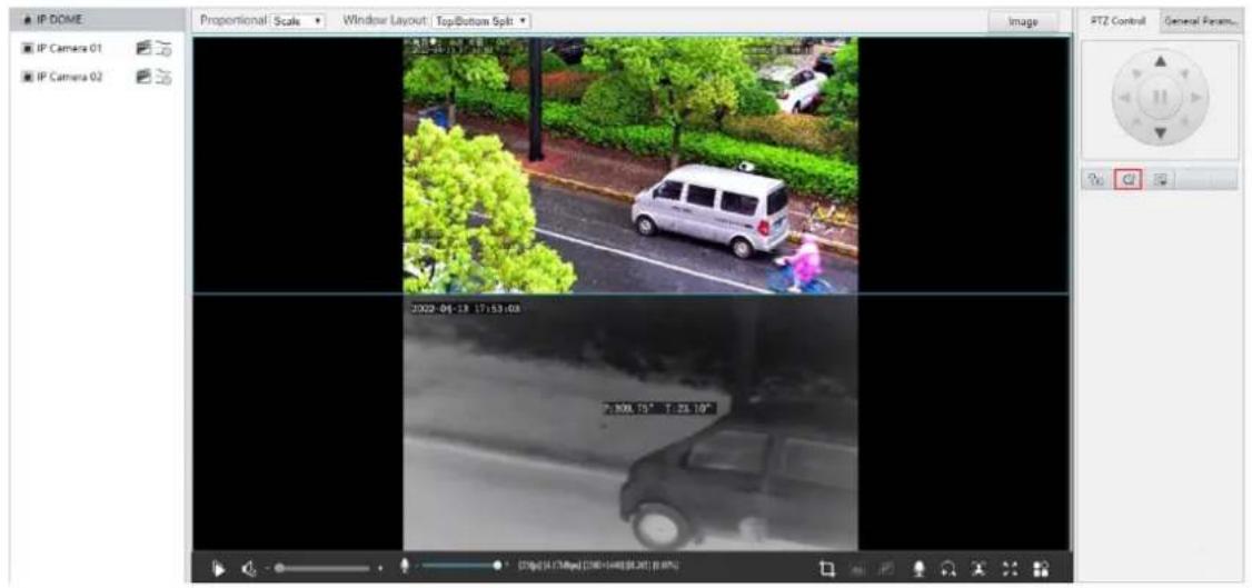
-
Click on the image and drag down/up to delineate a rectangular area to zoom in/out.
-
To exit, click

2.2.2 Area Focus
- Click in the PTZ control panel to enable area focus.
![Proportional Scale Main Stream Sub Stream Third Stream 20:22-04-13 17:33:04 Image Zoom Focus In Preset Preset 1 Preset 1 2 Preset 2 3 Preset 3 4 Preset 4 5 Preset 5 6 Preset 6 7 Preset 7 8 Preset 8 9 Preset 9 10 Preset 10 [25fps][4.108fps][2500=1410][H.265] [0.00%]](/content/2026/06/1364534/images/38b79ab5a664cb014f617a44a5546ef0e5b45b0b61d44bb76f5bbb2c723850ec.jpg)
-
Click on the image and drag to delineate a rectangular area to start auto focus in this area.
-
To exit, click
2.2.3 Preset
A preset position (preset for short) is a saved view used to quickly steer the PTZ camera to a specific position.
On the PTZ control panel, click Preset.
- Add a preset
-
Use the PTZ directional buttons to steer the camera to the desired position.
-
Select a preset not in use and click to edit the preset name.
-
Click to save.
- Call a preset
In the preset list, select the preset to call, and then click
- Delete a preset
In the preset list, select the preset to delete, and then click 📄
- Preset Sort
Click ☑ under the preset list. Then the configured presets will be displayed at the top of the list, sorted by preset ID in ascending order. When in sorting status, adding or deleting preset(s) will change the preset order immediately.

2.2.4 Patrol
Patrol is an action where a PTZ camera rotates between different types of actions. A patrol route consists of several actions.
Based on the different rotation tracks between two actions and the different route adding method, basic patrol are divided into 3 types: common patrol, scan patrol, and recorded patrol. Each PTZ camera can be configured with multiple patrol routes. To scan irregular areas, you can combine multiple basic patrol routes together.
1. Add a patrol route
Configure basic patrol route
- Add a common patrol route
In a common patrol route, the PTZ camera performs linear motion between presets.
- On the PTZ control panel, click Patrol.
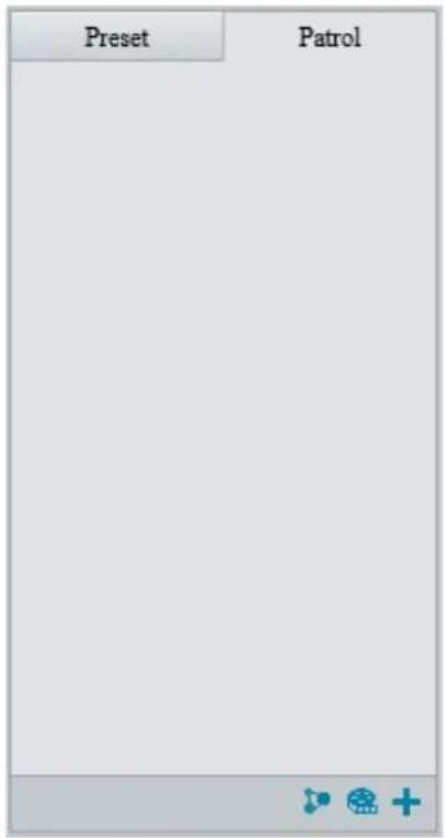
2. Click


- Set the route ID and name. On certain models, you may need to set the Patrol Type to Common Patrol.
- Click Add to add patrol actions.

5. Complete the action settings.
| Item | Description |
| Action Type | Supported action types includeMove Left, Move Right, Move Up, Move Down, Move Up Left, Move Up Right, Move Down Left, Move Down Right, Zoom, Goto Preset.Up to 64 actions are allowed. All action types exceptGoto Presetare recorded as 2 actions. You may use the up and down arrows to rearrange the patrol actions.NOTE!It is recommended to set the first action toGoto Preset. |
| Speed | Rotation speed.1-9 levels (from slow to fast).Preset Speed: Related to the preset speed level set inSetup > PTZ > Basic Parameters. The higher the preset speed level, the higher the preset speed. |
| Keep Rotating | When enabled, the camera keeps rotating and does not perform other actions. |
| Duration(ms)/Ratio | Set the duration/zoom ratio for the action. |
| Preset | Select the preset you want the camera to go to. |
| Stay Time | Set the dwell time after the camera performs an action.Range: 15s to 1800s.NOTE!The actual stay time supported may vary with camera. |
6. Click OK.
![Preset Patrol 1 [ceshi]](/content/2026/06/1364534/images/4b845c1ef15d61bf56c32a64cf116ef9df01dad29cd668492eed3de55fd89c31.jpg)
| Item | Description |
| Start patrol. | |
| Edit patrol route. | |
| Delete patrol route. |
- Add a scan patrol route
In a scan patrol route, the camera rotates from the start preset to the end preset in a specified gradient and direction.

NOTE!
This function is only available on certain models.
- Before adding a scan patrol route, set presets first. See Preset for details.
- On the PTZ control panel, click Patrol.

3. Click +
![Add Patrol Patrol Type Scan Patrol Route ID Route Name Start Preset End Preset Speed Tilt Gradient Initial Patrol Directi... [None] [None] 5 3.36 Clockwise OK Cancel](/content/2026/06/1364534/images/27867faf87ac2b8d0bd2733a214617ce7cadf61011dc4f78e4f230cf4274a966.jpg)
- Set the patrol type to Scan Patrol.
- Set the route ID and name.
- Set the patrol parameters.
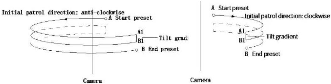
| Item | Description |
| Speed | Set how fast the camera rotate. 1 means the slowest, 9 means the fastest. |
| Tilt Gradient | The average division value of the vertical distance between the start and end presets.The greater the value, the shorter the patrol route. |
| Initial Patrol Direction | The direction of the first rotation from the start preset to the end preset. |
| Start/End Preset | Select a preset from the drop-down list as the start/end preset. The start and end presets must be different. |
- Record a patrol route
- On the PTZ control panel, click Patrol.
![Preset Patrol 1 [1]](/content/2026/06/1364534/images/b90ea7c0d5798e7ab22d46614ad82322175b17a0ee1c49fcba24b47c80f85fe6.jpg)
- Click ☐ to start recording. You can adjust the direction, rotation speed and zoom of the camera during recording. All movement data of the camera will be recorded.
- Click ■ to finish recording and the recording is saved as a patrol route automatically.
![Preset Patrol 1 [1] 2 [Mode Route]](/content/2026/06/1364534/images/999bf8b75751913e57ed4875254cb7c461f88c6b67bc984220c687f75924fbd7.jpg)
Configure composite route

CAUTION!
Please complete the configuration in Preset and Basic Patrol Route first.
For example: You want the camera to patrol the areas in the red box.

natural_image
Illustration of a mountain with a house and a small blue circle, no text or symbols present(1) Plan the patrol route, with common patrol and scan patrol as an example.
(2) Set presets.

natural_image
Illustration of a house with location pins and a mountain silhouette, no text or symbols present(3) Configure basic patrol routes.
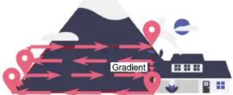
(4) Combine common patrol routes with scan patrol routes into a composite route.
(5) Call the configured composite patrol route.
- Go to Setup > PTZ > Patrol > Composite Routes.
![Select Channel Channel1 Route ID 1 Route Name 1 Add Delete Added 1/16 No. Action Type ID 1 Common Patrol [None] Zoom Focus Iris 20 Preset 20 21 Preset 21 22 Preset 22 23 Preset 23 On Off Save](/content/2026/06/1364534/images/af2a3e1d2c533ce26c9c908c614019b3818d54ddd106c0230af8c0e5022e44b3.jpg)
- Select a channel to configure and set the composite route ID and route name.
- Click Add to select the patrol route and ID.

NOTE!
- Up to 4 composite routes are allowed. Each composite route allows for up to 16 patrol routes.
• ✗ / ∧ / ∨ / ∨ : Select a route and click on the button to change the order.
- Click Save to save the settings.
- Click On to start patrol according to the composite route.
2. Call a patrol route
Manual calls take precedence over scheduled calls.
Auto tracking and trigger tracking is executed only within the duration that the camera stays at a position during common patrol.
Call basic patrol route manually
- On the PTZ control panel, click Patrol.
Select the patrol route to call and click to start patrol.
![Preset Patrol 1 [ceshi]](/content/2026/06/1364534/images/50c1f0db69a1e07e3ec734c20a522d786bb1db5a196e7db00f0538922f85aa95.jpg)
Call by schedule
- On the PTZ control panel, click Patrol.
![Preset Patrol 1 [1] 2 [Mode Route]](/content/2026/06/1364534/images/1d1c6afb4c565f0127f695458f67a9066d54f2fab101445c743467817fb0da0a.jpg)
- Click
![Enable Patrol Schedule Mon Tue Wed Thu Fri Sat Sun 00:00:00 ~ 23:59:30 Composite Routes 1[1] Please select Please select Please select Please select Please select Please select Please select Please select Please select Please select Please select Please select Please select Please select Copy To Select All Mon Tue Wed Thu Fri Sat Sun Copy Save](/content/2026/06/1364534/images/c9115de793db811c313dcc972b3a3f76305e9540d207f94a745208cfbe20d023.jpg)
- Select the Enable Patrol Plan checkbox.
- Select the patrol route to call and set a start time and an end time for it.
- Click OK.
2.3 General Parameters
Set general parameters to view image effects directly. On the live view page, click General Parameters.

3 Playback

NOTE!
- Edge recordings refer to video recorded on storage media of cameras; local recordings refer to video recorded on a local PC.
- Before you search for edge recordings, make sure that the camera has storage resources such as memory card, and the storage parameters in Storage are properly configured.
- Recording playback and download functions are only available on certain models.
- For dual-channel devices, you can set playback parameters for the channels separately.
On the home page, click Playback.
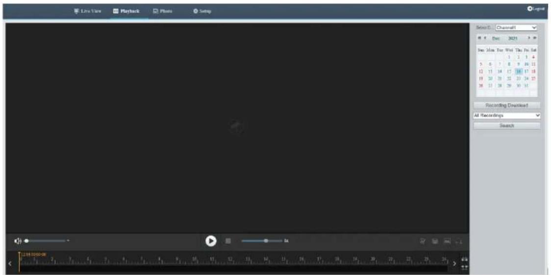
3.1 Playback Toolbar
| Button | Description |
| Adjust sound volume. Range: 1 to 100. | |
| Start playback. | |
| Pause playback. | |
| Stop playback. | |
| Clip video. | |
| Save. | |
| Adjust playback speed. The default speed is 1x. 2x plays faster, and 1/2x plays slower. - 2x rewinds fast. | |
| Take a snapshot. The snapshots are saved locally by default. You can change the storage location inLocal Parameters. | |
| Digital zoom. See Digital Zoom for details. | |
| Zoom in/out on the time scale. You can also use the scroll wheel to zoom. | |
| When the time scale is zoomed in, you can click to view the previous or next section of the video. | |
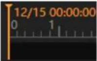 | Playhead. Drag the playhead to the desired point in the video. |
 | Playback timeline, including two colors:Blue: Normal recording.Red: Alarm recording. To view alarm recordings, you need to configure alarm-triggered recording. SeeAlarm-triggered Actionsfor details. |
3.2 Search and Playback

NOTE!
Certain cameras support simultaneous playback on two clients.
- For a multi-channel camera, select the channel first.
- Select the date on the calendar.
- Click All Recording in the list and then choose the recording type you want to search.
- Click Search. Search results are displayed.
- Double-click an item in the list to play the recording. The playback stops till it reaches the end of the
list or when you click to pause.

3.3 Recording Download
You can download videos or video clips in batches.
- Download recordings
- Click Recording Download.
- Choose the recording type, set a time range, and then click Search. Search results are displayed.
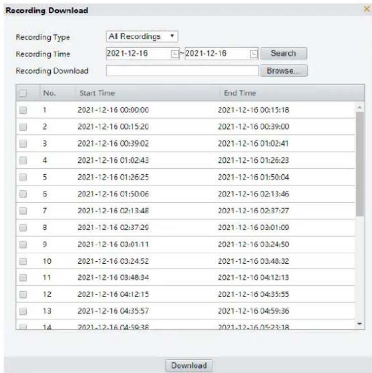
- Click Browse... and set the download destination.
- Select the checkboxes for the recordings you want to download and click Download.
- Download video clips
- Search for the video you want to clip. See Search and Playback.
- On the playback toolbar, click
- Click on the timeline to specify the clip by setting the start and end time.
- Click 📄. The clip turns cyan on the timeline.

- Click 📁. The Recording Download page appears.

NOTE!
Recording download functions supported may vary with device model. Please refer to the actual interface. The following diagrams are 2 typical examples.
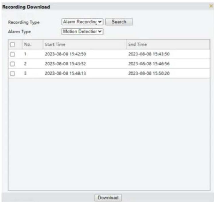

- Click Browse... and set the download destination.
- Select the checkbox for the clips you want to download and click Download.
4 Photo
View the photo storage status. See Storage for photo storage policy.

NOTE!
This function is only available on cameras with storage capabilities.
On the home page, click Photo.

| Item | Description |
| Refresh | Refresh the displayed content. |
| Export | Export the selected photos. |
| Delete | Delete the selected photos. |
| Export & Delete | Export the selected photos and delete them on the server. |
| Ascending Order | Arrange the items in chronological order. |
| Descending Order | Arrange the items in reverse chronological order. |
| Smart Server | Used to store smart snapshots. |
| Common Server | Used to store common snapshots. |

NOTE!
To allocate photo capacity, go to Setup > Storage > Storage.
5 Setup
5.1 Local Parameters
Set local parameters for your PC, including smart, video, recording and snapshot.

NOTE!
The local parameters displayed may vary with camera model.
- Go to Setup > Common > Local Parameters.
Smart
Intelligent Mark
On Off
Target Mark
√ Vehicle
√ Non-Motor Vehicle
Pedestrian
Object Metadata
On Off
Font Size
Small
Display Human Body Sn...
On Off
Note: When enabled, snapshots of human body will show in live view page. Only effective when face detection is enabled.
Video
Display Mode
Balanced
Protocol
TCP
Recording and Snapshot
Recording
Subsection By Time
Subsection Time (min)
30
When Storage Full
Overwrite Recording
Stop Recording
Total Capacity(GB)
10
Local Recording
MP4
Files Folder
C:\Users\d05019\WebPlugin_IPC\IPCUN\
Browse.
Open
Save
2. Set local parameters as needed.
| Item | Description | |
| Smart | Intelligent Mark | This function shall be used with Cross Line Detection, Intrusion Detection, Enter Area Detection, Leave Area Detection, Multi-Target Detection, and Face Detection. |
| Target Mark | When enabled, detection boxes will appear on the specified object type(s) on the live view page. | |
| Object Metadata | When this feature and snapshot are enabled (see Snapshot), snapshot thumbnails will show object metadata. | |
| Font Size | Set the font size of object metadata, including Large, Medium, and Small. | |
| Display Human Body Snapshot | When enabled, human body snapshots appear on the live view page.NOTE!Only effective when face detection is enabled. | |
| Video | Display Mode | Set the display mode according to the network status, including Min. Delay,Balanced, and Fluent (from low delay to high delay). You may also customize the display mode as needed. |
| Protocol | Set the protocol used to transmit media streams to be decoded by the PC, including TCP and UDP. | |
| Recording and Snapshot | Recording | Subsection By Time: Length of each local recording file. For example, 2 minutes.Subsection By Size: Size of each local recording file. For example, 10MB. |
| Subsection Time (min)/Subsection Size (MB) | Subsection Time (min): Available when Subsection By Time is selected. 1 to 60 minutes allowed.Subsection Size (MB): Available when Subsection By Size is selected. 10 to 1024MB allowed. | |
| When Storage Full | Overwrite Recording: When the local recording capacity is full, older recordings are overwritten automatically.Stop Recording: When the local recording capacity is full, recording stops automatically. | |
| Total Capacity (GB) | Allocate storage capacity for local recording.Range: 1 to 1024GB. | |
| Local Recording | Set the file format for saving local recordings, including TS and MP4. | |
| Files Folder | Set the location where snapshots and recordings are saved.ClickBrowse... to select the storage location.ClickOpento quickly open the folder.NOTE!The maximum length of the directory is 260 bytes. If the limit is exceeded, recording or snapshot during live view will fail. | |
3. Click Save.
5.2 Network
5.2.1 Basic Config
Complete the basic network configuration so the camera can communicate with other devices on the network.
1. Ethernet
- Go to Setup > Network > Basic Config.
- Configure Ethernet parameters.
- IPv4
Manual
(1) Select Manual from the Obtain IP Address drop-down list.
(2) Enter the IP address, subnet mask, and default gateway address. Make sure that the IP address of the camera is unique in the network.
(3) Click Save.

▶ PPPoE
Configure PPPoE to assign a dynamic IP address.
(1) Select PPPoE from the Obtain IP Address drop-down list.
(2) Enter the username and password provided by your ISP (Internet Service Provider).
(3) Click Save. The camera will be assigned an IP address.
Obtain Automatically(DHCP)
DHCP (Dynamic Host Configuration Protocol) is enabled by default. If a DHCP server is deployed in the network, the camera can automatically obtain an IP address from the DHCP server.
(1) Select Obtain Automatically(DHCP) from the Obtain IP Address drop-down list.
(2) Complete the settings as shown below.
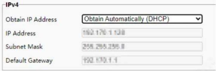
• IPv6
Obtain Automatically(DHCP)
The default mode is Obtain Automatically(DHCP). In this mode, the IP address is assigned by the DHCP server.
Manual

(1) Choose Manual.
(2) Enter the IPv6 address, prefix length and default gateway. Make sure that the IPv6 address is unique in the network.
-
Set the MTU value, port type and operating mode.
-
MTU: Maximum transmission unit. Input an appropriate value. The greater the value, the higher the transmission efficiency, and the higher the delay.
- Port Type: The default type is FE Port.
- Operating Mode: The default is Auto-negotiation.

-
Click Save.
-
Wi-Fi
Go to Setup > Network > Basic Config > Wi-Fi.
- Connecting to Wi-Fi
This status only appears in factory mode, indicating that the device has not been configured for any Wi-Fi mode yet. It disappears once a Wi-Fi mode has been configured and will reappear if the device is restored to factory defaults.
- Wi-Fi Mode
This mode appears when the device is connected to network through a Wi-Fi or the one-click pair function in NVR.
- Select Wi-Fi from the drop-down list. You can view the current network status.
| SSID | None |
| IP Address | 0.0.0.0 |
| Subnet Mask | 0.0.0.0 |
| Default Gateway | 0.0.0.0 |
| Strength |
- Choose the Wi-Fi network to connect to from the Wi-Fi network list. The list displays all Wi-Fi networks around the device. If needed, you can click Search to search for the surrounding Wi-Fi networks again.
| SSID | Channel | MAC Address | Authentication | Encryption | Strength | Strength(dBm) |
| IPCWiFi7E2952 | 6 | 30:1b:97:07:7d:38 | WPA-PSK WPA2-PSK | TKIP | -41 | |
| DZ1807112_08773 | 3 | b4:0F:3b 62:7f:61 | WPA-PSK WPA2-PSK | CCMP-TKIP | -43 | |
| DZ1710057_08687 | 1 | 48:7d:2e:7c:89:2e | WPA-PSK WPA2-PSK | CCMP | -47 | |
| zbbwiffient5 | 11 | 00:0a:f5 9f:82:84 | WPA-PSK WPA2-PSK | CCMP | -51 | |
| DZ1508019_00383 | 6 | 88:25:95:12:0a:5e | WPA-PSK WPA2-PSK | CCMP-TKIP | -56 | |
| IPCWiFi7F3988 | 6 | a0:9E:10 a9:34:14 | WPA-PSK WPA2-PSK | TKIP | -57 | |
| Uni_Warless | 1 | 4c:m:5:e4:83:f8:c0 | WPA-PSK WPA2-PSK | CCMP-TKIP | -58 |
- Set Wi-Fi parameters under Wi-Fi Configuration according to the Wi-Fi network to be connected.
| SSID | Xiaomi_923B |
| Authentication | WPA-PSK WPA2-PSK |
| Password | ●●●●●●●● |
| Confirm | ●●●●●●●● |
| Encryption | CCMP |
| Obtain IP Address | DHCP |
| MTU | 1500 |
You can configure parameters according to the following table.
| Item | Description |
| SSID | Automatically filled in after selecting a Wi-Fi network for connection. |
| Authentication | Select the authentication mode that is consistent with the Wi-Fi network to be connected.Supports OPEN, SHARED, WPA-PSK WPA2-PSK, and WPA2-enterprise mode.OPEN: No password is required.SHARED: Enter a password of 5, 13, or 16 characters, which can be plain digits, plain letters, common characters, or a combination of two or three types.WPA-PSK WPA2-PSK: Enter a password between 8 to 63 characters, which can be plain digits, plain letters, common characters, or a combination of two or three types.WPA2-enterprise: Commonly used in enterprise-level networks and needs to use with a Radius server. |
| Username | Required in WPA2-enterprise mode only. Enter the username registered in the Radius server. |
| Password | Enter the Wi-Fi password. When the authentication mode is WPA2-enterprise, enter the password registered in the Radium server. |
| Confirm | Enter the Wi-Fi password again to confirm. |
| Encryption | Select the same encryption type as the Wi-Fi network to be connected. |
| Obtain IP Address | Choose an IP obtain mode as needed: DHCP or Manual. |
| MTU | Set the maximum transmission unit (MTU). Default: 1500. The larger the MTU value, the more efficient the communication, but the greater the transmission delay. Please set an appropriate MTU value that balances both factors. |
• Wi-Fi Hotspot Mode
- Select Wi-Fi Hotspot from the drop-down list. In this case, IPC can be used as a hotspot for other devices to connect to.
- Set Wi-Fi hotspot configurations under Hotspot Settings.

You can configure parameters according to the following table.
| Item | Description |
| SSID | Set the name according to the rules on the interface. |
| Password | Set the password according to the rules on the interface. |
| Confirm | Enter the password again to confirm. |
| Channel | Select the appropriate channel according to your actual needs. |
| Gateway Address | Set a valid gateway address according to the rules on the interface.Note:When the device is connected to a wired network, the device's Wi-Fi hotspot function will be disabled and will be automatically enabled when disconnected from the wired network. |
- Off
Disable the configured Wi-Fi mode.
3. Mobile Network
- Go to Setup > Network > Basic Config > Mobile Network.

- Configure the mobile network parameters.
| Item | Description | ||
| APN | The Access Point Name (APN) is a network operator for a dedicated network and the name can be customized. Note: • A network access technology.• APN determines which access methods the device uses to access network. | ||
| Username | The username of the APN. | ||
| Password | The password of the APN | ||
| Confirm | Enter the password of the APN again to confirm. | ||
| Authentication Mode | Choose an authentication mode: None (default), PAP, CHAP, and Auto. | ||
| MTU | Maximum transmission unit. | ||
| Auto-Switch SIM Card | • If not selected, you can manually choose to use either the built-in or external card for mobile network connection;• When selected and dual SIM cards are in use, if SIM A fails to connect to the mobile network, the system will automatically switch to SIM B after 10 minutes. If the connection still fails after 3 switches, the device restarts. If SIM B remains disconnected after restart, the system will switch to SIM A once more. If the final attempt also fails (3 switches + 1 restart + 1 final switch), no further actions will be taken. Please check the SIM card status. 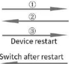 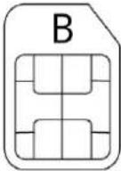 Note: • The built-in SIM card is integrated into the device and cannot be removed, while the external SIM card is removable. Note: • The built-in SIM card is integrated into the device and cannot be removed, while the external SIM card is removable. | ||
| • The device can only recognize only one SIM card at a time. | |||
3. Click Save.
4. DNS
The DNS service is a globally distributed service that translates human readable domain names into numeric IP addresses. To use the DNS service, you need to configure DNS server information.
- Go to Setup > Network > Basic Config > DNS.
- Set the preferred and alternate DNS server addresses. The default settings are as follows.
Preferred DNS Server
8.8.8.8
Alternate DNS Server
8.8.4.4
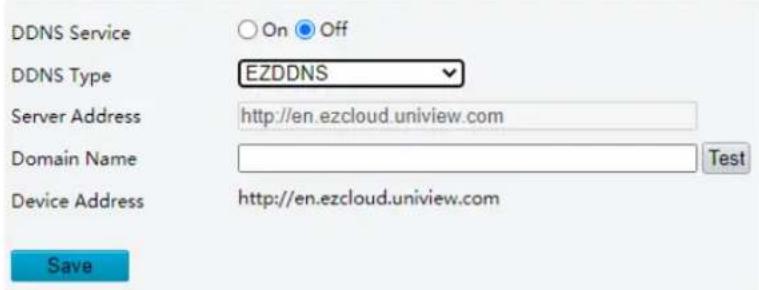
5. DDNS
DDNS (Dynamic Domain Name Server) can map the dynamic IP address of the camera to a fixed domain name and so users can access the camera using the easy-to-remember domain name.
- Go to Setup > Network > Basic Config > DDNS.
- Enable DDNS Service.
DDNS Service
On Off
DDNS Type
DynDNS
Server Address
www.dyndns.com
Domain Name
Username
Password
Confirm
Save
- Select the DDNS type.
DynDNS/NO-IP: Third-party DDNS service provider. Enter the server address and domain name provided by your DDNS service provider.
EZDDNS: Uniview DDNS service. Enter a domain name and then click Test to check its availability.
- Click Save.
6. Port
1. Go to Setup > Network > Basic Config > Port.
| HTTP Port | 80 |
| HTTPS Port | 443 |
| RTSP Port | 554 |
Note: Modifying the RTSP port number will cause the device to restart.
- You can use the default ports. If a port entered has been used for other services, you need to change the port to avoid conflict.

CAUTION!
- If the HTTP port number you entered is being used by another service, a message indicating port conflict will appear. Ports 23, 81, 82, 85, 3260, and 49152 are reserved for other purposes and cannot be used.
-
In addition to the above port numbers, the system can also dynamically detect other port numbers that are already in use.
-
HTTP/HTTPS Port: If you change the HTTP/HTTPS port number, then you need to add the new port number after the IP address when logging in. For example, if the HTTP port number is set to 88, you need to use http://192.168.1.13:88 to log in to the camera.
-
RTSP Port: Real-Time Streaming Protocol port, enter an available port number.
-
Click Save.
7. Port Mapping
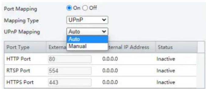
Configure port mapping so users can access your camera on the LAN from the Internet.
- Go to Setup > Network > Port > Port Mapping.
- Enable Port Mapping.
- Select the mapping type.
• UPnP
Save
Auto: When enabled, the camera will negotiate external ports with the router automatically. Make sure UPnP is enabled on the router.
Manual: In this mode, you need to enter external ports manually and make sure the ports entered are available; otherwise, port mapping does not take effect.
- Manual
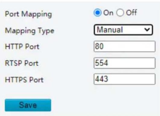
If your router does not support UPnP, you need to set the external port numbers manually. Make sure the entered ports are available; otherwise, port mapping does not take effect.
Inactive will be displayed in the Status column if the port number entered is already in use by another service.
4. Click Save.
8. 802.1x
802.1x enhances network security for your intranet by performing port-based authentication before allowing the device to access the LAN. Only successfully authenticated devices are allowed to access the LAN.
- Go to Setup > Network > Basic Config > 802.1x.
- Enable 802.1x.
- Choose a protocol type.
- EAP-MD5
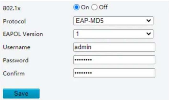
(1) Choose the EAPOL version according to the protocol version on the network switch.
(2) Enter the device username and password, confirm the password.
- EAP-TLS

(1) Choose the EAPOL version according to the protocol version on the network switch.
(2) Enter the device username.
(3) Click ▼ to choose a client certificate and a CA certificate (see Certificate Management for details)

NOTE!
You must use an imported client certificate and a CA certificate for the camera to pass authentication. The camera cannot pass authentication with a self-signed certificate and a default certificate.
4. Click Save.
5.2.2 Service Configuration
1. Email
Configure E-mail so that the camera can e-mail an alarm message to the specified email addresses when an alarm occurs.
1. Go to Setup > Network > Service Config > E-mail.


- Set the sender and recipient information.
| Item | Description |
| Sender Name | Enter the device name. |
| Sender Address | Enter the device IP. |
| SMTPServer/SMTP Port | Enter the IP address and port number of the sender's SMTP server.The default SMTP port number is 25. |
| TLS/SSL | When enabled, emails will be encrypted by TLS or SSL during transmission.NOTE!If SMTP supports TLS/SSL, it tries SSL first to establish a secure connection for email sending. |
| Snapshot Interval | Choose a snapshot interval: 2s, 3s, 4s, or 5s. |
| Attach Image | When enabled, an alarm e-mail with attached snapshots taken at set interval will be sent after an alarm occurs. For some alarm types, only one snapshot will be taken and there's no need to set snapshot interval.       [rk83] [rk83] 1. Select the Attach Image checkbox.2. Enable Snapshot and set the snapshot resolution as needed. There's no need to set snapshot schedule. 1. Select the Attach Image checkbox.2. Enable Snapshot and set the snapshot resolution as needed. There's no need to set snapshot schedule. |
| Server Authentication | Enable SMTP server authentication to secure e-mail transmission. |
| Username/Password | Enter the username and password of the SMTP server. NOTE!The email only shows the sender name. Username will not be displayed.217.2.1.196-ly 217.2.1.196-ly: Motion Detection 03-07 10:23 489 KBThe password allows special characters. |
| Recipient Name/Address | 1. Enter the recipient names and email addresses.2. Click Test to test the email sending function. |
3. Click Save.
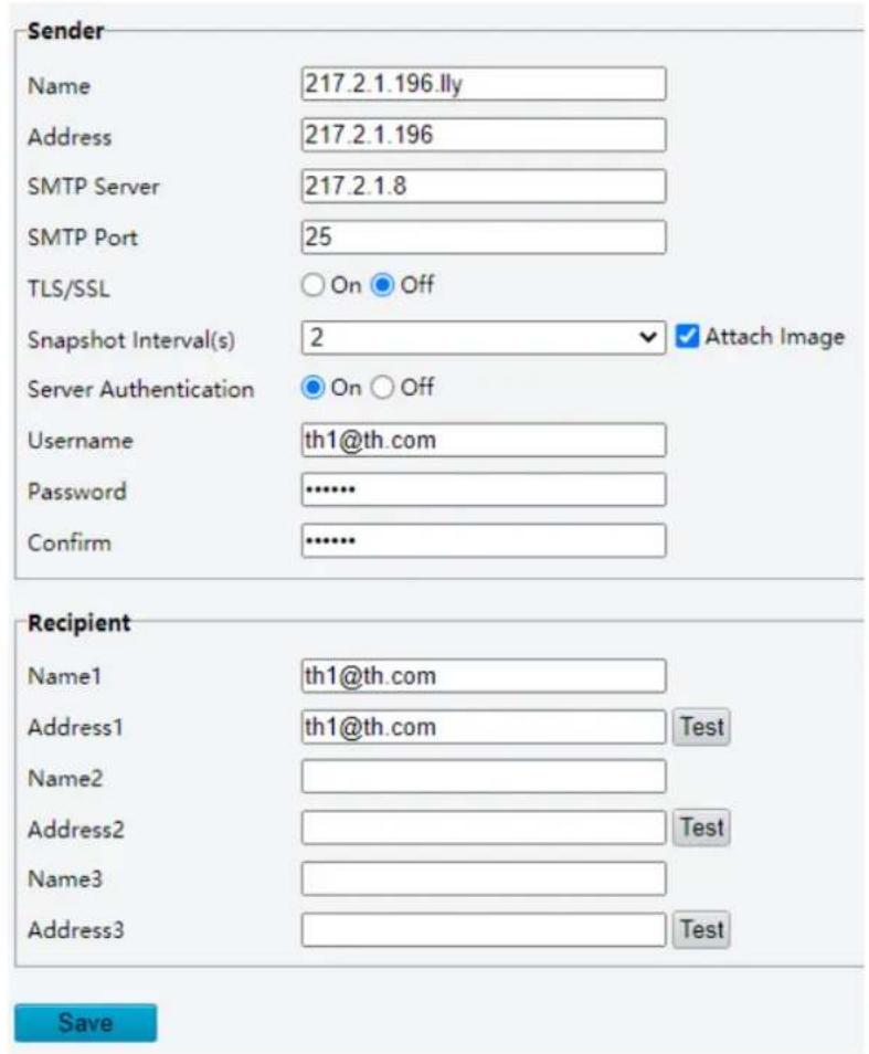
2. SNMP
The Simple Network Management Protocol (SNMP) allows the camera to be remotely managed by a management server. The camera can be configured to support SNMP and send messages to the management server for important events or status change.
- Go to Setup > Network > Service Config > SNMP.

- Click On to enable SNMP.

NOTE!
On certain device models, SNMP is enabled after an upgrade to the latest version. It is normal.
3. Set SNMP parameters.
- SNMPv3

NOTE!
Before you enable SNMPv3, make sure SNMPv3 is supported both on your camera and the server.

| Item | Description |
| SNMP Type | The default is SNMPv3. |
| Password | Set an authentication password. |
| Confirm | Confirm the authentication password by entering it again. |
| Password | Set an encryption password. |
| Confirm | Confirm the encryption password by entering it again. |
| Trap Server Address | It is filled in automatically after you complete management server configuration. |
| SNMP Port | The default is 161. You may change it as needed. |
- SNMPv2

| Item | Description |
| SNMP Type | A message will appear to remind you of potential risks and prompt for your confirmation after you choose SNMPv2. To choose SNMPv2 anyway, click OK to ignore the reminder. |
| Read Community | The default is public. You may change it as needed, but make sure you also change it on the server; otherwise, authentication will fail. |
| Trap Server Address | Go to Setup > Network > Platform Access > Management Server to configure the server address. |
| SNMP Port | The default is 161. You may change it as needed. |
- Click Save.
3. QoS
QoS (Quality of Service) can alleviate network delay and network congestion by prioritizing different services.
- Go to Setup > Network > Service Configuration > QoS.
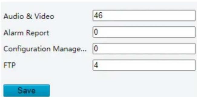
- Assign a priority level (0 to 63) for each service. The greater the value, the higher the priority. For example, the camera first ensures smooth audio and video in the case of network congestion.

NOTE!
The same QoS rules must also be configured on the router or network switch.
- Click Save.
4. RTSP
The real-time streaming protocol (RTSP) provides remote control over media streams, such as start, pause, fast-forward, and stop, but it does not transmit data itself.
- Go to Setup > Network > RTSP.
RTSP

Note: Enabling/disabling RTSP will restart the device.
Save
- Choose whether to enable RTSP. When disabled, video playing will be unavailable on the Live View page.
- Click Save.
5. ONVIF (ANR)
If the network connection between the camera and the stream receiving address is disconnected, the camera can store videos; and after the network connection is restored, the camera can retransfer the video stored during the interruption period to the stream receiving address.

5.2.3 Platform Access
1. Intelligent Platform
Configure intelligent platform to receive smart snapshots from the camera. A camera can be managed by two intelligent servers.
Local snapshot cannot be enabled when the number of subscriptions has reached the upper limit.
If local snapshot has been enabled, when the number of subscriptions reaches the upper limit, higher-priority subscriptions will take precedence, and local snapshot will be disabled.

NOTE!
- The number of subscriptions supported may vary with camera.
- Priority level of subscription from different platforms: Platform 1 > Platform 2 > LAPI subscription > WebSocket subscription.
• Video&Image Database
- Go to Setup > Network > Platform Access > Intelligent Platform.
- Select the Enable checkbox.
- Choose Video&Image Database as the protocol.

| Item | Description |
| Protocol Version | Choose the protocol version: VIID_2017, VIID_2018, VIID_2018 (multi-channel).Note:When choosing VIID_2018 (multi-channel), you need to enter the video channel ID for each channel. |
| Server IP | Enter the IP address of the platform. |
| Server Port | Use the default 5196. |
| Device ID | Input a valid ID according to on the instructions and keep it the same on the platform.The ID shall comply with VIID protocol. |
| Username | Enter the username for authentication, which must be the same as that configured on the platform. |
| Platform Access Code | Enter the password for authentication, which must be the same as that configured on the platform. |
| Confirm Platform Access Code | Input the password again for confirmation. |
| Coordinate Mode | Used to position structured information on the image, which must be in the same format as that on the platform, Percentage Mode, Pixel Mode, or Normalized Mode. |
| Connection Mode | Use the default: Short Connection. |
| Report Data Type | Choose the type(s) of data to be sent to the intelligent platform: Motor Vehicle, Non-Motor Vehicle, Person, and Face. |
| Status | Offline: The camera is disconnected from the platform.Online: The camera is connected to the platform. |
- UNV
- Go to Setup > Network > Platform Access > Intelligent Platform.
Enable
| Protocol | UNV |
| Server IP | 0.0.0.0 |
| Server Port | 5196 |
| Camera No. | HIC6642-IR@X22-VC |
| Device No. | EZIPC0 |
| Status | Offline |
- Select the Enable checkbox.
- Configure the parameters.
| Item | Description |
| Server IP | Enter the IP address of the platform. |
| Server Port | Use the default 5196. |
| Camera No. | Keep it the same as the device ID on the management platform. |
| Device No. | Custom device ID. |
| Status | Offline: The camera is disconnected from the platform.Online: The camera is connected to the platform. |
- Click Save.
- FTP
- Go to Setup > Network > Platform Access > Intelligent Platform.
- Select the Enable checkbox.
- Choose FTP as the protocol.
√ Enable
| Protocol | FTP | Configure FTP |
| Status | Online |
- Click Configure FTP. A page as shown below appears.
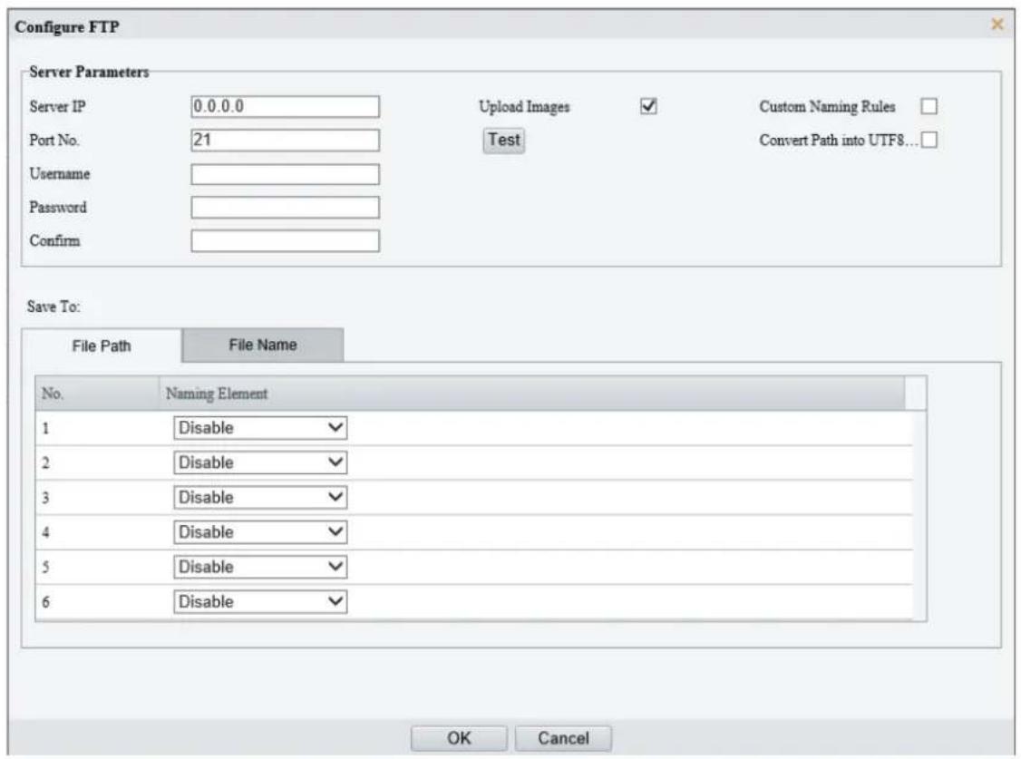
5. Set server parameters.
| Item | Description |
| Server IP | Enter the IP address of the FTP server. |
| Port No. | Use the default 21. |
| Username | Enter the username used for accessing the FTP server. |
| Password | Enter the password used for accessing the FTP server. |
| Test | Click to test the connection to the FTP server. |
| Upload Images | Select the checkbox to enable uploading smart snapshots.Overwrite Storage: After the number of photos in the lowest-level folder reaches the set threshold, new photos will overwrite older photos in the folder. For example, the storage path is “\IP\date”, the lowest-level folder is the level-2 folder named “date”. When the number of photos uploaded on Jan. 4, 2022 reaches 1000 (default value), new photos overwrite old photos in the 20220104 folder.NOTE!To choose Overwrite Storage, make sure the last naming element of the files is the image sequence number.Overwrite At (image): The default is 1,000, up to 100,000 is allowed. |
| Custom Naming Rule | Select the checkbox, and then you can customize the file naming rules as needed. For the naming rules, see File Path in step 6. |
| Covert Path into UTF8 | Select the checkbox, and the path will be converted into UTF8 format. |
6. Configure the image storage path.
| Item | Description |
| File Path | Six levels are allowed. If not set, the default path “\IP Date\Intelligent” will be used, where “Intelligent” means smart snapshots. |
| File Name | Naming element: Up to 20 fields are allowed. If not set, sequence numbers will be used as file names, for example, “1, 2, 3”, etc.Naming rule: Format string: prefix <(front string) front length % > suffix. |
7. Click Save.
2. EZCloud
Add the camera to EZCloud so you can access the camera anytime, anywhere from your mobile phone for live view, playback, camera configuration, etc.

NOTE!
- You can add the camera to EZCloud using UNV link or EZLive or through the EZCloud website.
- UNV link and EZLive are free apps that can be downloaded from app stores, including iOS and Android versions. You need to download and install the app on your mobile phone in order to access your camera from your mobile phone. The following takes UNV link as an example to describe the operations.
- You can add the camera to EZCloud with or without a cloud account. A cloud account is required if you want full functionalities on the app. Some functions, such as cloud upgrade, will not be available if the camera is added to EZCloud without a cloud account.
Go to Setup > Network > Platform Access > EZCloud. Check that EZCloud is enabled.

Option 1: Add cameras on the UNV-Link app
- Scan the QR code on the EZCloud page or search UNV-Link in the app stores to download and install the app.
- Register an account and log in to the app.
- Tap Add Device on the home screen.
- Scan the register code on the camera or on the Quick Guide, and then tap OK.
- Select a connection method according to the actual situation.
- Follow the on-screen instructions to add the device.

NOTE!
The actual operations may be slightly different, please follow the instructions in the app.
Option 2: Add cameras on the EZCloud website
- Visit en.ezcloud.uniview.com using a web browser.
- On the login page, click Sign Up and follow on-screen instructions to create an account.
3. Log in to the website.

4. Go to Device Management > My Cloud Devices and click Add.
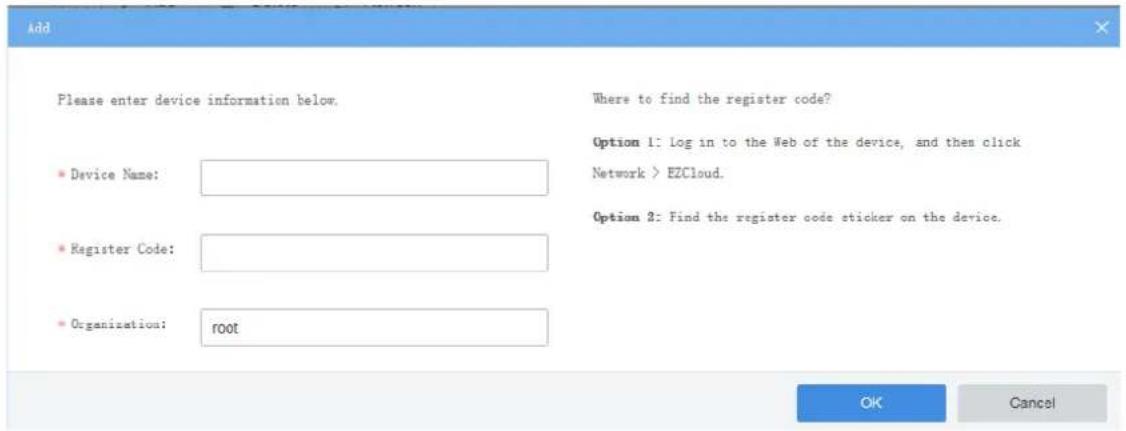
| Item | Description |
| Device Name | Enter the device name. |
| Register Code | Enter the register code. |
| Organization | Select an organization for your camera.By default, the root organization is selected. You may add or delete organizations under Organization Management > My Cloud Organizations. |
5. Click OK.
6. Click Save.
-
Check whether the camera is online.
-
EZCloud website: Go to Device Management > My Cloud Devices.
- Camera's web interface: Go to Setup > Network > EZCloud.
3. IoT Platform
1. Go to Setup > Network > Platform Access > IoT Platform.

- Enter the UDP platform IP and set the report interval. Use the default platform port (9892).
- Click Save.
4. WebSocket
WebSocket can connect your camera to a third-party platform and enable remote management of the camera from the third-party platform, including viewing device version and capabilities, control PTZ, and receive alarms.
1. Go to Setup > Network > Platform Access > WebSocket.
WebSocket
Destination IP

Destination Port

Device ID

Authentication Key

Confirm Authentication Key

Online Status
Offline
Save
2. Set the parameters.
| Item | Description |
| WebSocket | Select to enable or disable WebSocket. |
| Destination IP | Enter the IP address of the third-party platform. |
| Destination Port | Enter the listener port of the third-party platform. |
| Device ID | The default device ID is the device's serial number. You can set a device ID as needed. |
| Authentication Key | Enter the authentication key used to connect the camera to the third-party platform. Make sure the authentication keys configured on the camera and the third-party platform are the same.NOTE!If you first choose not to enable Authentication Key and then enable it after the camera is connected to the platform, authentication does not take effect immediately; it will take effect when the next time the camera is successfully connected to the platform. |
| Confirm Authentication Key | Confirm the authentication key by entering it again. |
| Online Status | Check whether the device is successfully connected to the third-party platform. |
3. Click Save.
5. Alarm Platform
The camera can automatically report alarms to a third-party server. You need to configure the third-party information such as server IP, server port, and protocol type first.
1. Go to Setup > Network > Platform Access > Alarm Platform.
Server IP

Port

Transfer Protocol Type

Device ID

Save
2. Select Enable.
-
Set the server IP and port, and then click Test to check if the server is available.
-
Choose a protocol type: HTTP or HTTPS.
- Enter the device ID (0-32 characters: letters, digits, underscores, etc.).

NOTE!
Third-party servers can distinguish between devices reporting alarm information using device ID. If you have multiple devices, ensure each is configured with a unique device ID.
- Click Save.
5.3 Video & Audio
For dual-channel devices, you can set video and audio parameters for the channels separately.
5.3.1 Video
1. Video
1. Go to Setup > Video & Audio > Video.

2. Select a capture mode for your camera.
The Extended Encoding function is available only when the capture mode is greater than 8MP.

After you change the capture mode, the encoding settings will be reset to defaults and some models of cameras will restart.
3. Set stream parameters.
The streams are independent of each other and can be set with different resolutions, frame rates, video compression formats, etc. Only the main stream supports full resolution.

NOTE!
- The fourth and fifth streams are only available on certain models.
- Before configuring the fifth stream, you need to enable the fourth stream first.

| Item | Description |
| Video Compression | Select a video compression standard for your camera: H.265, H.264 or MJPEG.NOTE!When H.265 or H.264 is selected, Image Quality is not available; When MJPEG is selected, Bit Rate, I Frame Interval, Smoothing, SVC and U-Code are not available.The bit rate restores to the default when you switch between H.264 and H.265. |
| Resolution | Select a video resolution for your camera. The higher the resolution, the clearer the image. |
| Frame Rate(fps) | Select the frame rate.NOTE!To ensure image quality, the frame rate shall not be greater than the reciprocal of the shutter speed. |
| Bit Rate(Kbps) | Set the bit rate. Range: 128 to 16384.NOTE!The bit rate range may vary with device model. |
| Bitrate Type | Select the bitrate type.CBR: The camera keeps a specific bit rate by varying the quality of video streams.VBR: The camera keeps the quality of video streams as constant as possible by varying the bit rate. |
| Image Quality | Configurable when Bitrate Type is set to VBR.The closer the slider is to Quality, the higher the bit rate, and the higher the image quality.The closer the slider is to Bit Rate, the lower the bit rate, and the image quality will be affected. |
| I Frame Interval | Set the number of frames between I-frames. A shorter interval presents better image quality but consumes more bandwidth and storage. |
| GOP | Group of Pictures, defines the basic pattern of the video stream encoded with I and P frames. |
| Smoothing | Set the smoothness of the video stream. Drag the slider to choose whether smoothness or clarity takes precedence.NOTE!Smoothing is recommended for fluent video in a poor network environment. |
| SVC | When enabled, Scalable Video Coding (SVC) can achieve temporal layers to extract partial bit streams and achieve fractional frame rates, reducing bandwidth consumption without compromising the video quality. |
| U-Code | Select the U-code mode.Basic Mode: Reduces the bit rate by about 25%.Advanced Mode: Reduces the bit rate by about 50%. |
-
Set the BNC output format, PAL or NTSC.
-
Click Save.
2. Adaptive Streams
The bit rate of the media stream is automatically adjusted according to the network conditions.

NOTE!
- This function is only available on certain models.
- This function is enabled by default on certain models.
- It's recommended to enable Adaptive Streams in a poor network environment.
-
To enable adaptive streams, you need to choose the TCP protocol at Setup > Commons > Local Parameters; otherwise, adaptive streams cannot be enabled.
-
Go to Setup > Video & Audio > Video > Adaptive Streams.
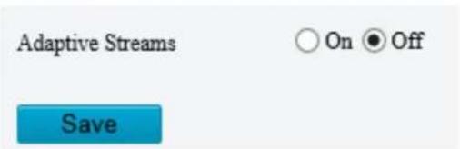
- Enable Adaptive Streams.
- Click Save.
5.3.2 Snapshot
Configure basic snapshot parameters and scheduled snapshot.
- Go to Setup > Video & Audio > Snapshot.

NOTE!
- For dual-channel devices, you can set snapshot parameters for the channels separately.
- When you configure e-mail and FTP, you only need to enable Snapshot and set the resolution and maximum size; it's unnecessary to configure the scheduled snapshot.

- Enable Snapshot, set the resolution and maximum size of snapshots.
- Set the snapshot mode.
Schedule: Set a snapshot time. For example, with Snapshot Interval set to 20s, Number to Snapshot set to 3, and snapshot time set to 16:00:00, the camera will take a snapshot at 16:00:00, 16:00:20 and 16:00:40. You can click +to add a snapshot time by choosing from the list or by adjusting based on a listed time.

To delete a snapshot time, click
Repeat: Set a snapshot interval. For example, with snapshot plan set to 16:00:00 to 20:00:00 on Monday, Repeat Interval set to 120s, Snapshot Interval set to 20s, and Number to
Snapshot set to 2, the camera will take a snapshot at 16:00:00, 16:00:20, 16:02:00 and 16:02:20.
a Select Repeat and set the repeat interval. A valid repeat interval is an integer within the range of 1 to 86400. The snapshot interval * number of snapshots to take cannot be greater than the interval (Snapshot Interval * Number of Snapshot cannot be greater than Interval).

b Select the Enable Snapshot Plan checkbox and set the snapshot plan. See Arming Schedule for details. A 24/7 snapshot plan is enabled by default.

NOTE!
• The time periods cannot overlap.
- Up to 4 time periods are allowed.
- Set the snapshot interval (unit: second) and number to snapshot (1, 2, or 3). For example, if the interval is set to 1s and the number to snapshot is set to 2, the camera will take 2 snapshots (take one first and then take another after 1 second).
- Click Save.
5.3.3 Audio
1. Audio
- Go to Setup > Video & Audio > Audio.
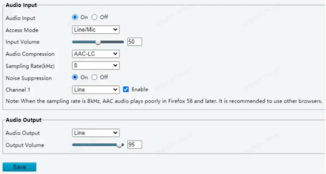
- Set audio input parameters.
| Item | Description |
| Audio Input | Enable/disable audio input.NOTE!If audio is not needed, it is recommended to turn it off to improve camera performance. |
| Access Mode | Choose the audio input mode; Line/Mic or RS485.NOTE!This function is not available on dual-channel cameras. |
| Input Volume | Drag the slider or input a value to set the input volume. |
| Audio Compression | Choose the audio compression format: G.711U or G.711A. |
| Sampling Rate(kHz) | Choose a sampling rate, 8kHz or 16kHz. The higher the sampling rate, the better the sound quality. |
| Noise Suppression | It can reduce noises and improve audio output quality. |
| Channel 1/Channel 2 | Select the Enable checkbox to enable audio input for Channel 1 or Channel 2 (if available). Only one channel can be enabled.Channel 1 supports Mic (default) and Line.Channel 2 is available on certain models only. |
3. Set audio output parameters.
| Item | Description |
| Audio Output | Choose an audio output mode,LineorSpeaker.·Line: A speaker or an earphone needs to be connected.·Speaker: Speaker mode.Note:The audio output modes supported may vary with device model. Please refer to the actual interface |
| Output Volume | Set the output volume using the slider. |
4. Click Save.
2. Audio File
- Go to Setup > Video & Audio > Audio.
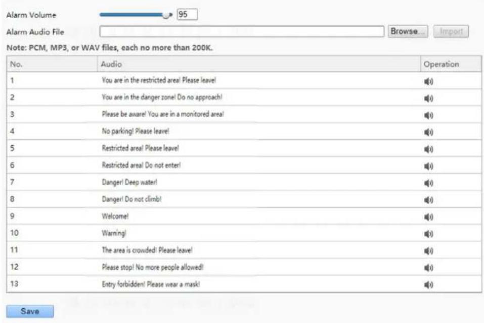
2. Set audio file parameters.
| Item | Description |
| Alarm Volume | Drag the slider or input a value to set alarm volume. |
| Alarm Audio File | ClickBrowse...to import audio files.To play an audio file, click.To edit audio contents, click.To delete an audio, click.NOTE!This function is available only on certain models. Up to 5 audio files are allowed.Built-in audio files may vary depending on the smart functions supported by the device.Certain models without smart functions provide built-in alarm audios and support user-imported audios. |
3. Click Save.
5.3.4 ROI
Region of Interest (ROI) ensures image quality of specified areas on the image at low bit rate.
- Go to Setup > Video & Audio > ROI.


2. Set ROI areas.
(1) Click + to add a ROI area. The area is a rectangle by default. Up to 8 areas are allowed.

(2) Adjust the position and size of the area or draw an area as needed.
Adjust the position and size of the area.
- Point to a border of the area and drag it to the desired position.
- Point to a handle of the area and drag to resize it.
Draw an area.
Click on the image and drag to draw an area.

NOTE!
When setting the ROI, you can click to lock the scene to prevent pan/tilt movement caused by triggered detection rules, and click to unlock the scene after finishing setting the ROI.
5.3.5 View Cropping
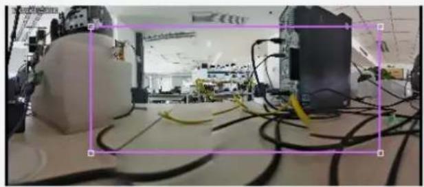
You can crop the live video to keep only the area of interest and transmit the cropped video by sub or third stream to save bandwidth and storage.
- Go to Setup > Video & Audio > View Crop.
- Select the Enable View Crop checkbox. A rectangular appears on the image. You may drag to resize or relocate the rectangular on the image.
√ Enable View Crop
natural_image
Interior view of a robotics lab with robotic arm and connected cables (no visible text or symbols)
Save
- Choose a cropping mode.
- Field of View Mode: The camera ensures the size of the specified area. Choose a stream type, set the cropping size and resolution.
Crop Mode
Field of View Mode
Output Stream Type
Sub Stream
Crop Size
20:9
Resolution
2880×1264
- Resolution Mode: The camera ensures the resolution of the specified area first. Choose a stream type, set the resolution.

- Click Save. The live and recorded video only show the specified area (rectangular) of the image.
5.3.6 Media Stream
1. Media Stream
You can configure a media stream for your camera so that media contents from the camera such as audio and video can be transmitted over the network and played immediately on a third-party client rather than being downloaded first.
- Go to Setup > Video & Audio > Media Stream.
| Stream Profile | Protocol | Destination IP | Destination Port | Persistent | Status | + |
- Click to add a media stream.
- Complete the media stream settings.
| Item | Description |
| Stream Profile | Select a stream type for the camera to transmit media contents to a third-party client. |
| Destination IP | Enter the IP address of the device receiving media streams. |
| Protocol | The camera transmits data to a third-party client through the specific protocol.The default protocol is RTMP. |
| Persistent | Set whether to automatically establish the configured media stream after the camera restarts. |
4. Click OK.
2. RTSP Multicast
RTSP multicast allows third-party players to request RTSP multicast media streams from the camera through the RTSP protocol.
- Go to Setup > Video & Audio > Media Stream > RTSP Multicast Address.
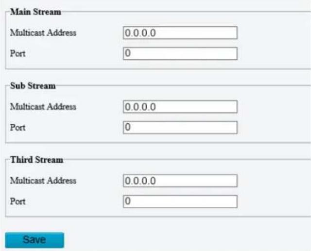
-
Set the multicast address and port number (multicast address range: 224.0.1.0 to 239.255.255.255, port number range: 0 to 65535).
-
Click Save.
5.4 PTZ
5.4.1 Basic PTZ Settings
Go to Setup > PTZ > Basic Settings.
1. Preset Image Freeze
After you enable Preset Image Freeze, as the camera moves from one preset to another, the live view window keeps displaying the image of the previous preset until the camera stops at the next preset.
Preset Image Freeze

2. Stop PTZ Control After Timeout
When controlling the PTZ manually, avoid communication loss that may cause continuous abnormal rotations of the PTZ. The PTZ will stop rotation when the predefined timeout period is reached.

3. PTZ Speed

- Speed Level between Presets: Set the rotation speed of the camera between presets.
- Manual Operation Speed Level Range: Set the speed level for manually controlling the PTZ on the live view page.

NOTE!
- The higher the manual operation speed level, the higher each PTZ speed level on the live view page.
- When both manual operation speed level and PTZ speed on the live view page are set to the maximum, the PTZ speed reaches the upper limit.
4. PTZ Rectification
Check for PTZ zero point offset and perform rectification.

- Rectify manually: Click Rectify to start rectification immediately.
- Rectify automatically: Select the Enable Auto Rectification checkbox and set the execute time. The camera automatically performs PTZ rectification at the set time.
5. Power Off Memory
When enabled, the system will record the last position of the PTZ and lens in case of power failure. This function is enabled by default.
Power Off Memory
On Off
5.4.2 Auto Guard
The PTZ camera can automatically operate as configured (e.g., go to a preset or start patrol) if no operation is made within a specified period.

NOTE!
Before use, you need to add a preset or a patrol route. See Preset and Add a patrol route for details.
1. Go to Setup > PTZ > Auto Guard.
![Auto Guard On Off Mode Preset ID [None] Idle State(s) 60](/content/2026/06/1364534/images/755de93f9397ea76203b9ef9030818a8000a11acfe76ecb2c53e7c636008207f.jpg)
Save
2. Enable Auto Guard and complete the settings.
| Item | Description |
| Mode | Select the Auto Guard mode, including Preset and Patrol. |
| ID | Select the desired preset or patrol route. |
| Idle State | Set the idle duration for the camera to start auto guard. |
3. Click Save.
5.4.3 Pan/Tilt Limit
You can filter out the undesired scenes by limiting the pan and tilt movements.
1. Go to Setup > PTZ > Limit.

2. Set the pan and tilt limits. Take the tilt limit configuration as an example:
(1) Use ▲ to move the camera to the desired upper tilt limit position.
(2) Click ✗ above the rectangle to set the position as the upper tilt limit.

(3) Use ▼ to move the camera to the desired lower tilt limit position.
(4) Click ✗ below the rectangle to set the position as the lower tilt limit.

| Item | Description |
| Rotate the camera to the limit. | |
| Delete the limit. |
- Click Save.
- Select the Enable PTZ Limit checkbox.
5.4.4 Preset Snapshot and Patrol Resumption
Go to Setup > PTZ > Patrol.
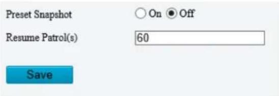
- Preset Snapshot
The camera takes a snapshot at each preset during patrol and uploads the snapshots to FTP.

NOTE!
Before use, please configure FTP and Snapshot first.
- Resume Patrol
In the event of a patrol interruption, the camera can automatically resume the patrol after a specified time period.
5.4.5 Orientation
1. North Calibration
Calibrate the north direction.
- Go to Setup > PTZ > Orientation.
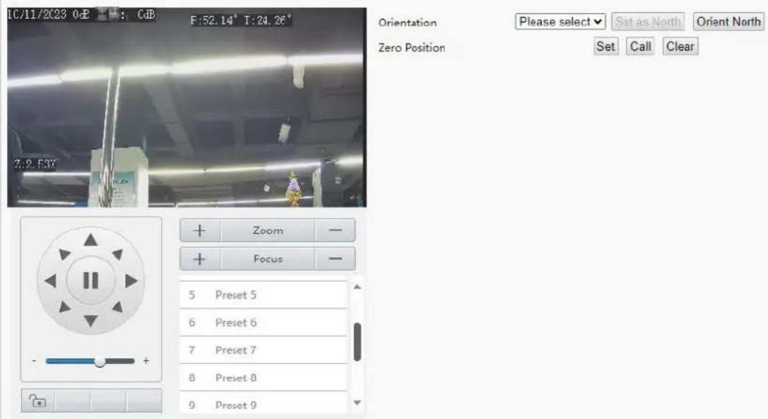
- Select the mode to calibrate the camera to north.
| Item | Description |
| Manual | Set the north direction manually.After calibration, you can click Orient North to rotate the camera to the calibrated north direction. |
2. Zero Position
Configure a zero position for the camera as the initial position for pan and tilt movement.
- Go to Setup > PTZ > Orientation.
- Move the camera to the desired position.
- Click Set to set the position as the home position.
| Item | Description |
| Call | Move the camera to the zero position. |
| Clear | Clear the zero position. |
5.5 Image
5.5.1 Image
For dual-channel devices, you can set image parameters for the two channels separately.
1. Scenes
A scene is a collection of image parameters preset in the camera for users to choose according to the actual scene.
- Go to Setup > Image > Image.
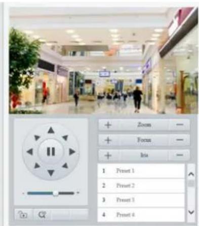

2. Click Scenes.
Scenes
| No. | Current | Image Scene Template | Image Scene Name | |
| 1 | ✓ | Scene1 | ||
| 2 | ○ | ✓ | Scene2 | |
| 3 | ○ | ✓ | Scene3 | |
| 4 | ○ | ✓ | Scene4 | |
| 5 | ○ | ✓ | Scene5 | |
Default
3. Set the parameters.
| Item | Description |
| Current | Shows the scene that is currently in use.NOTE!To apply a scene, click the corresponding radio button in the Current column. The scene is selected as the current scene, and the corresponding image parameters apply automatically. |
| Image Scene Template | The camera provides multiple scenes for you to choose according to the actual scene. After you select a scene, the corresponding image settings apply automatically (you may also fine-tune image settings as needed).Common: For outdoor scenes.Indoor: For indoor scenes.Road Highlight Compensation/Park Highlight Compensation: For capturing license plates in roads, parks, etc.WDR: For high-contrast situations.Custom: For customizing a scene.Test: For testing.Standard: For common scenes, indoor and outdoor.Vivid: Provides extra saturation based on the Standard scene.Bright: Provides extra brightness based on the Standard scene.Starlight: For lowlight environments.Face: For capturing faces in motion in complicated scenes.Person And Vehicle: For monitoring motor vehicles, non-motor vehicles, and pedestrians in road scenes.Intrusion Prevention: For perimeter protection scenes.VLOG: For outdoor scenes. In this scene, the face brightness is 50, the minimum duration is 5s, the white balance mode is outdoor, and auto exposure and face metering are also enabled. |
| Image Scene Name | Choose scene names corresponding to the scene templates. The scene names will be used in image scene switching (see Image Scene Switch). |
2. Image Enhancement
1. On the Image page, click Image Enhancement.
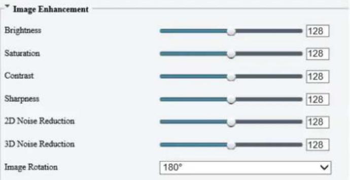
bar
| Image Enhancement | Value | | --------------------- | ----- | | Brightness | 128 | | Saturation | 128 | | Contrast | 128 | | Sharpness | 128 | | 2D Noise Reduction | 128 | | 3D Noise Reduction | 128 |2. Set the image enhancement parameters.
| Item | Description | |
| Brightness | The overall lightness or darkness of the image. | |
 |  | |
| Low brightness | High brightness | |
| Saturation | The intensity or vividness of colors in the image. | |
 |  | |
| Low saturation | High saturation | |
| Contrast | The difference between the lightest and darkest tones in the image. | |
 |  | |
| Low contrast | High contrast | |
| Sharpness | The definition of edges in the image. | |
 |  | |
| Low sharpness | High sharpness | |
| 2D Noise Reduction | Reduce noise by individually analyzing each frame, which may cause image blur. | |
| 3D Noise Reduction | Reduce noise by analyzing the difference between successive frames, which may cause image smearing or ghosting. | |
| Image Rotation | The rotation of the image. | |
 |  | |
| Normal | Flip vertical | |
 |  | |
| Flip horizontal | 180° | |
 |  | |
| 90° clockwise | 90° anti-clockwise | |
| Gain Adjustment Mode | Adjusts the image contrast.·Adaptive: Suitable for complex scenes with multiple objects or people.·Histogram: Highlights high-temperature object but may lose some details. Suitable for scenes requiring emphasis on high-temperature objects.·Linear: Suitable for scenes with large areas of homogeneous objects, such as forests or skies. Note:This function is only supported on certain thermal imaging devices. Please refer to the actual interface. | |
To restore defaults, click Default.
3. Exposure

NOTE!
- The exposure settings may vary with device model.
- The default settings are scene-adaptive. Use default settings unless modification is necessary.
1. On the Image page, click Exposure.

2. Set the exposure parameters.
| Item | Description |
| Exposure Mode | Select the exposure mode.Automatic: The camera automatically set the optimum shutter speed according to the scene.Custom: User can set exposure parameters as needed.Shutter Priority: The camera adjusts shutter as priority to adjust the image quality.Iris Priority: The camera adjusts iris as priority to adjust the image quality.Indoor 50Hz: Reduce stripes by adjusting the exposure time.NOTE!➢ Stripe effect: The high-contrast condition in an image caused by uneven light energy received by the sensor.➢ Using this mode in brighter environments aids in adjusting the stripe effect in the image with linear stripe suppression.Indoor 60Hz: Reduce stripes by adjusting the exposure time.NOTE!Using this mode in brighter environments aids in adjusting the stripe effect in the image with linear stripe suppression.Manual: Fine-tune image quality by setting shutter, gain and iris manually.Low Motion Blur: Control the minimum shutter to reduce motion blur in faces captured in motion. |
| Shutter(s) | Shutter is used to control the light that comes into the lens. A fast shutter speed is ideal for scenes in quick motion. A slow shutter speed is ideal for scenes that change slowly.NOTE!This parameter is configurable when Exposure Mode is set to Manual, Shutter Priority, or Custom.If Slow Shutter is disabled, the reciprocal of the shutter speed must be greater than the frame rate. |
| Gain | Control image signals so that the camera can output standard video signals in different light conditions.NOTE!This parameter is configurable when Exposure Mode is set to Manual or Custom. |
| Slow Shutter | Increase image brightness in low light conditions.NOTE!This parameter is configurable when Exposure Mode is not set to Iris Priority and Image Stabilization is disabled. |
| Slowest Shutter | Set the slowest shutter speed for exposure. |
| Compensation | Adjust the compensation value as required to achieve the desired image effect.NOTE!This parameter is configurable when Exposure Mode is not set to Manual. |
| Linear Stripe Suppression | Adjust the linear stripes in the image.Range: 1 to 9, the default is 5. The greater the value, the more obvious the linear stripe suppression effect is, but it may cause overexposure in the image. Please configure this according to the actual scene.NOTE!This parameter is configurable when Exposure Mode is set to Indoor 50Hz or Indoor 60Hz. |
| Restore Auto Exposure(min) | Set the duration for the camera to restore the automatic exposure status before iris adjustment. |
| Metering Control | Perform luminance statistics on the images captured by the device, automatically adjust the exposure value, and output properly exposed images with optimal brightness. The default is the Center-Weighted Average Metering, you may configure this according to the actual scene.Center-Weighted Average Metering: Measure light mainly in the central part of the image.Evaluative Metering: Measure light in the specified area of the image, suitable for scenes where the target and the background contrast widely.Spot Metering: Measure light in a small spot, smaller than evaluative metering, with more accurate light control. If used in brighter areas, the metered area will be properly exposed but darken other areas. If used in darker areas, the metered area will be properly exposed (unable to increase the brightness of the spot) and brighten other areas.Face Metering: Adjust image quality in poor lighting or back lighting conditions by controlling the brightness of captured faces in face scenes.NOTE!This parameter is configurable when Exposure Mode is not set to Manual. |
| Day/Night Mode | Automatic: The camera automatically switches between day mode and night mode according to the ambient lighting condition to output optimum images.Day: The camera outputs high-quality images in daylight conditions.Night: The camera outputs high-quality images in low-light conditions.Input Boolean: The camera switches between day mode and night mode according to the Boolean value input from a connected third-party device.NOTE!The Input Boolean option is only available on certain models. |
| Day/Night Sensitivity | Light threshold for switching between day mode and night mode. A higher sensitivity value means that the camera is more sensitive to the change of light and is therefore more easily to switch between day mode and night mode.NOTE!This parameter is configurable when Day/Night Mode is set to Automatic. |
| Day/Night Switching(s) | Set the length of time before the camera switches between day mode and night mode after the switching conditions are met.NOTE!This parameter is configurable when Day/Night Mode is set to Automatic. |
| WDR | Suitable for high-contrast scenes. WDR can balance the brightness in the bright area and dark area, and provide clear image with more details.On/Off: User needs to identify WDR scenes, and manually enable or disable WDR as needed.Smart/Automatic: The device can automatically identify typical WDR scenes, and then enable or disable WDR.Note:When WDR is enabled, some other functions may not be supported. Please refer to the actual interface. |
| WDR Level | Adjust the WDR level.NOTE!Level 7 or higher is recommended if there is a high contrast between the bright and dark areas in the scene. In the case of low contrast, it is recommended to disable WDR or use level 1 to 6. |
| WDR On/Off Sensitivity | When WDR is set to Automatic, adjust the parameter to change the WDR switching sensitivity. |
| Suppress WDR Stripes | Suppress the stripes in the image caused by the flickering light in WDR mode. When enabled, the camera automatically adjusts the shutter and frequency to minimize stripes. |
To restore defaults, click Default.
4. Smart Illumination
- On the Image page, click Smart Illumination.

- Enable Smart Illumination.
- Set the smart illumination parameters.
| Item | Description |
| Illumination Mode | Infrared: The camera uses infrared light illumination.White Light / Smart White Light: The camera uses white light illumination.Warm Light: The camera uses warm light illumination.Laser: The camera uses laser light illumination.Note:Before you select Warm Light, please set the Port Mode to Illumination (go to Setup > System > Ports & Devices > Serial Port).This parameter is configurable when Control Mode is set to Custom Level. Range: 0 to 100. 0 is the weakest, 100 is the strongest.WhenSmart Illuminationis enabled and illumination modeis set to Smart White Light:➢ Alarm-trigger enabled: when an alarm is triggered, during the daytime, the white light blinks; at night, the white light is on steadily, otherwise, the white light is on faintly.➢ Alarm-trigger N/A or disabled: when an alarm is triggered, during the daytime, the white light is off; at night, the white light is on steadily, otherwise, the white light is on faintly. |
| Control Mode | Global Mode: The camera automatically adjusts illumination and exposure to achieve the balanced image effect. Some areas might be overexposed if you select this option. This option is recommended if you focus on the monitoring range and image brightness.Overexposure Restrain: The camera automatically adjusts illumination and exposure to avoid regional overexposure. Some areas might be dark if you select this option. This option is recommended if you focus on the clarity of the monitoring center area.Preset-Road/ Preset Mode: This mode offers a strong overall illumination and is recommended for monitoring wide-range scenes, for example, road.Preset-Park: This mode offers a uniform illumination and is recommended for monitoring small-range scenes with many obstacles, for example, park.Preset-Spotlight Mode: This mode provides more concentrated illumination with a longer distance and is recommended for monitoring long-distance scenes.Custom Level: This mode allows you to manually control the intensity of illumination.Custom Level(Always On): In this mode, the illumination is always on.PTZ Control: In this mode, the module can notify the PTZ to turn on the illumination via a serial port protocol. The PTZ can control the intensity of illumination automatically.Note:The illuminator control modes supported may vary with device model. Please refer to the actual interface. |
| Illumination Level | Set the intensity of the illuminator. The greater the value, the higher the intensity. 0 is off.Near-illumination Level: Recommended for near focus scenes.Mid-illumination Level: Recommended for medium distance focus scenes.Far-illumination Level: Recommended for far focus scenes.Note:This parameter is configurable when Control Mode is set to Custom Level. |
To restore defaults, click Default.
5. Focus
- On the Image page, click Focus.
| Focus | |
| Focus Mode | One-Click Focus |
| Scene | Normal |
| Zoom Speed | 1 |
| Min. Focus Distance(cm) | 10 |
| Max. Zoom Ratio | 40 |
- Set the focus parameters.
| Item | Description |
| Focus Mode | Auto Focus: Automatic focus control based on the current light conditions.Manual Focus: Manual focus control.One-Click Focus: Automatic focus in the event of rotation, zoom, and preset call.One-Click Focus (IR): Recommended for low light scenes.One-click Focus (Locked): Recommended for road highlight scenes. |
| Advanced Settings | Automatic focusing is triggered when the PTZ rotates, significant temperature shifts occurs, or preset switches at night. You can configure advanced settings to prevent automatic focusing in specified scenarios when not required.3 scenarios (trigger sources) supported: PTZ Rotation, Temperature Drift, and Nighttime Preset. |
| Advanced SettingsShield Focus Tri... PTZ Rotation Temp. Drift Nighttime PresetOK Cancel | |
| Note:This function is only supported on certain device models and the trigger sources supported for focus shield supported may vary with device model. Please refer to the actual interface. | |
| Scene | Normal: Common monitoring scenes such as road, park, etc.Long Distance: Long-distance monitoring scenes |
| Zoom Speed | 1: Low zoom speed. Recommended for common scenes.2: High zoom speed. Recommended when Quick Focus is enabled. |
| Min. Focus Distance | Select the minimum focus distance. |
| Max. Zoom Ratio | Choose an upper limit for digital zoom: 22, 44, 88, 176, or 352. |
- To restore the default settings, click Default.
6. White Balance
White balance is used to eliminate unnatural color casts in images under different color temperatures for optimal color reproduction.
- On the Image page, click White Balance.

- Set the white balance parameters.
| Item | Description |
| White Balance | Adjust the red and blue gains of the image to remove unrealistic color casts.Auto/Auto 2: Automatically adjust the red and blue gains according to the lighting conditions. If there are still color casts in Auto mode, try Auto 2 mode.Fine Tune: Manually adjust the red and blue offsets.Sodium Lamp: Automatically adjust the red and blue gains for optimal color reproduction in sodium light sources.Outdoor: Recommended for outdoor scenes where the color temperature varies widely.Locked: Keep the current color temperature.Area White Balance: Suitable for large pure color scenes and complex color scenes. By customizing the white balance area, this mode improves the accuracy of white balance correction and reduces color casting.Note:If you chooseArea White Balance, you can adjust the size and location of the bounding box on the live view page manually.To prevent the selected location in the bounding box from changing due to pan/tilt movement, please click to enable scene lock before adjusting it. When finished, click to disable scene lock. |
| Red/Blue Offset | Set the red/blue offset.Note:This parameter is configurable whenWhite Balanceis set toFine Tune. |
To restore defaults, click Default.
7. Defog
Defog is used to improve image visibility in foggy, hazy and other low-visibility scenes.
- On the Image page, click Advanced.


NOTE!
This function is only available when WDR is disabled.
- Set the defog parameters.
| Item | Description |
| Defog | Select the defog mode, includingAutomatic, On, and Off.InAutomaticmode, the camera automatically adjusts the defog intensity according to the fog concentration for clear images. |
| Defog Intensity | Adjust the defog intensity.In a heavy-fog environment, the higher the defog level, the clearer the image; in a fog-free or light-fog environment, there is not much difference between levels 1 to 9.NOTE!Optical defog is available on certain models.To enable optical defog, selectOnand set the defog intensity to 6 or higher, or selectAutomatic.Optical defog is automatically turned on in thick fog, and the image changes from color to black and white. |
To restore defaults, click Default.
8. Heatwave Reduction
Adjust the heatwave reduction level to improve the image quality by eliminating the stripes in the image caused by heatwaves.

NOTE!
- Please set the heatwave reduction level according to the actual needs.
- For devices that support heatwave reduction, when in dual-channel mode, only channel 2 supports the heatwave reduction function.
Heatwave Reduction

9. Lens Info

NOTE!
- This function is only available on cameras with external lenses.
- When using a P-IRIS lens with Z/F function, connect the iris control cable to the Z/F port of the camera.
1. On the Image page, click Lens Info.

2. Set the lens parameters.
| Item | Description |
| Lens Type | Select the lens type, includingCommonand IR. |
| Lens Model | Select the lens model, includingLENS-DC-IRIS,LENS-DM0734P,etc.NOTE!The lens models supported may vary with device model. |
| Aperture Control | Select automatic or manual iris control.NOTE!This parameter is configurable whenLens Typeis P-IRIS. |
| F-Number | Set the f-number to adjust the iris opening manually. |
| Use Recommended Value | The camera optimizes the iris opening based on the current lighting conditions. |
To restore defaults, click Default.
10. Dewarping
Dewarping is used to correct distorted images caused by wide-angle lenses.
1. On the Image page, click Advanced.

2. Enable Dewarping and set the dewarping level as needed.
To restore defaults, click Default.
11. Image Stabilization
A camera mounted outdoors may be shaken by external forces (e.g., wind), causing image blur. In this case, you can enable image stabilization to ensure the image quality.
1. On the Image page, click Advanced.

2. Select On or Off to enable or disable image stabilization, and configure the parameters.
| Item | Description |
| Stabilization Intensity | Default: 5. The greater the value, the higher the stabilization capability.Caution:As the level increases, part of the images may be cropped. Please configure the level as needed. |
| Stabilization Accuracy Correction | Default: 0. Adjust the correction value to eliminate individual errors, making the displayed image more stable. Valid range: -100 to 100.Note:This function is only supported on certain device models. Please refer to the actual interface.The optimal correction value varies with device models. Please adjust the value as needed. |
To restore defaults, click Default.
12. Non-Uniformity Correction
Non-uniformity correction improves image quality by correcting the non-uniformity of pixels caused by different response rates of thermal units.
1. On the Image page, select Channel 2 and click Advanced.

2. Select the non-uniformity correction mode.
- Shutter Compensation: In this mode, the live video may be lost.
- Background Compensation: In this mode, scene change may occur during image collection.
13. Reduce Vertical Stripe Noise
This function helps remove vertical stripes in images caused by the sensor or external temperature.
1. On the Image page, select Channel 2 and click Advanced.

2. Drag the slider or enter a number to set the intensity. The greater the value, the blurrier the image.
natural_image
Black-and-white photo of two individuals wearing hooded garments, hands visible in foreground (no text or symbols)Before

natural_image
Person wearing a full-body medical gown, standing in front of another person's arm (no visible text or symbols)After
14. Thermal Imaging Palette
The camera offers a variety of color display options for thermal imaging. The rainbow palette has a strong contrast and a clear distinction between colors of different temperatures, ideal for pinpointing objects in environments with subtle temperature differences.
- On the Image page, select Channel 2 and click Advanced.
- Select the appropriate thermal imaging palette for your camera.
Common Palette "Rainbow 3"
Thermal Imaging Palette
Imaging Palette Example
Rainbow 3

Common Palette "White Hot"
Thermal Imaging Palette
Imaging Palette Example
White Hot

15. Image Scene Switch
Configure image scene switch so the camera can automatically switch image scenes according to the configured time schedules or linked presets.
- Go to Setup > Image > Image Scene Switch.

-
Choose a switch mode.
-
Timed Switch: Switch to a specified scene at a set time.
-
Preset Switch: Switch to a specified scene at a set time specified for a specified preset.
-
Configure the switch mode parameters.
- Timed Switch
| Item | Description | |||
| Auto Switching | When auto switch is enabled and switching conditions are met, the system switches scenes automatically. The list includes the default scene. | |||
| Schedule | The default scene (No.1) takes effect when the current time is not within the listed periods. You can add up to 5 periods and assign a scene for each period. The periods must not overlap. Click to set time. | |||
| No. | Auto Switching | Schedule | Image Scene Name | |
| 1 | Default Scene | 1 | ||
| 2 | ☐ | ~ | 2 | |
| 3 | ☐ | ~ | 3 | |
| 4 | ☐ | ~ | 4 | |
| 5 | ☐ | ~ | 5 | |
| Image Scene Name | Choose a scene for each period. The scenes are configured on theScenespage (see Scenes). | |||
| No. | Auto Switching | Schedule | Image Scene Name | |
| 1 | Default Scene | 1 | ||
| 2 | ☐ | ~ | 2 | |
| 3 | ☐ | ~ | 3 | |
| 4 | ☐ | ~ | 4 | |
| 5 | ☐ | ~ | 5 | |
- Preset switch
Choose linked presets for locations. You can set up to 4 locations and link them to different presets (which need to be configured in advance, see Preset), and configure 4 schedules for the locations, each schedule includes different periods and corresponding image scenes.
![Enable Auto Switch Switch Mode Preset Switch Link Preset Location1 [None] No. Auto Switching Schedule Image Scene Name 1 Default Scene 1 2 □ ~ 2 3 □ ~ 3 4 □ ~ 4 5 □ ~ 5 Save](/content/2026/06/1364534/images/3e88eb8381bb92cf20fe0dcc66821f437833098f12261326ef8644bad04325d4.jpg)
- (Optional) Select the Enable Auto Switch checkbox.
- Timed Switch
The camera switches to the linked image scene at the start time of a period.
The camera switches to the default scene at the end time of a period, or to the corresponding scene at the start time of the next period.
The camera switches image scene at once when Auto Switch is enabled.
- Preset Switch
The camera switches scenes when calling a linked preset.
The camera checks the current time when calling a preset:
- If the current time is within a listed period, the camera switches to the scene corresponding to the period.
- If no scene has been set for the period, the camera switches to the default scene.
-
If the current time is not within any listed periods, the camera switches to the default scene.
-
Click Save.
16. Engineering Parameters
During lens rotation, the camera may lose focus, causing unclear images. In this case, you can initialize the lens to refocus.
- Go to Setup > Image > Engineering.
- Reset lens.
• To reset manually, click Reset.
- To reset automatically, select the Enable Auto Initialization checkbox and set an execution time.
natural_image
Close-up of a dark, textured surface with light reflections, possibly industrial or mechanical components (no visible text or symbols)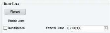


- Click Save.
17. Video Standard
Select the P/N standard for video capture to suppress the stripes in the image.
- Go to Setup > Image > Image.
- Click Video Standard.

- Select the P/N standard from the Video Standard drop-down list. Even if you switch the capture mode in Video, the P/N standard configured in this page still prevails.
5.5.2 OSD
On Screen Display (OSD) are characters displayed with video images, for example, camera name, date and time.

NOTE!
• This function may vary with device model.
- For dual-channel cameras, you can set OSD parameters for the channels separately.
Configure OSD displayed on the live video.
- Go to Setup > Image > OSD.

- Configure parameters in the OSD Toolbar

NOTE!
OSD operations supported may vary with device model.
| Item | Description |
| Enable | Select the checkboxes in the Enable column to overlay the corresponding OSD contents on live video.NOTE!Up to 10 OSDs are allowed. |
| Overlay OSD Content | Set OSD content you want to overlay. Point to the OSD content, click , select the OSD content from the drop-down list or customize it.NOTE!An OSD content takes effect only when the Enable checkbox is selected.Some models allow multiple OSD contents in one overlay area. |
| X-Axis/Y-Axis | Specify the exact position of the OSD by entering the X and Y coordinates.The top left corner of the image is the origin (0, 0), the horizontal axis is the X-axis, and the vertical axis is the Y-axis.NOTE!You can also drag an OSD to the desired position: point to the OSD box in the preview window, and drag when the cursor shape changes. |
| Upload Picture | This parameter is available only when the Overlay OSD Content is set to Picture Overlay.3. ClickBrowse...to select the picture you want to overlay.4. ClickUpload,then the picture is displayed on the live video. |
| ScrollOSD | This parameter is available only when the Overlay OSD Content is set to Picture Overlay.1.Enter the text you want to overlay.2.The text appears on the live video and scrolls from right to left. |
| Copy | After configuring the OSD for one channel,you can clickCopyto copy the OSD content and style of the channel to other channels. |
3. Overlay OSD Contents.
Custom: Customizes the OSD contents.
Date & Time: Displays the current date and time of the camera according to the set format (content style), for example, Friday, 25 March, 2022 14:25.
PTZ Coordinates: Specify the exact position of the PTZ camera. For example, P: 165.42°, T: 1.49°. P stands for horizontal coordinates, T stands for vertical coordinates.
➢ Zoom: Displays the zoom information of the PTZ, for example, Z: 1.00X.
➢ Preset: Displays current preset ID on live video, for example, Preset 1.
Serial Port: The IPC will receive and parse the serial port information in correct format and display the information in the live view window. Only some models support this function.
Direction: Displays the coordinates of the 8 directions of the PTZ camera, including the basic directions: East, South, West, North, and the intermediate directions: Northeast, Southeast, Northwest, and Southwest.
People Counting: Displays people flow information (number of people entering/leaving), crowd density information (number of people present), or face detection information (number of people entering/leaving) on live video. You need to enable and configure People Flow Counting, Crowd Density Monitoring, or Face Detection.
Time: Displays the current time of the device.
Date: Displays the current date of the device.
Picture Overlay: Displays locally imported pictures. You may set the picture transparency according to your need.
➢ ScrollOSD: The OSD text displays on the live video and scrolls from right to left.
Network Port: The IPC will receive and parse the network port information in correct format and display the information in the live view window.
Device Latitude and Longitude Coordinates: Displays the latitude and longitude coordinates of the device location.
➢ Motor Vehicle&Non-Motor Vehicle&Pedestrian Count: Displays motor vehicle/non-motor vehicle/pedestrian counting information on live video. You need to enable Multi-Target Detection and Motor Vehicle&Non-Motor Vehicle&Pedestrian Count first.

NOTE!
- To disable an OSD, clear the OSD content or clear the corresponding Enable checkbox.
• Some models allow multiple OSDs.
- Set the OSD display style.
| Item | Description |
| Effect | Choose a display effect: Background, Stroke, Hollow, or Normal. |
| Font Size | Choose a font size: X-large, Large, Medium, or Small. |
| Font Color | Click to choose a font color. |
| OSD Inverse | When enabled, the OSD content color is opposite to the live view color. |
| Min. Margin | Choose a minimum distance between the OSD area and the edge of image:None: Zero margin.Single: One-character margin.Double: Two-character margin. |
| Date Format | Choose a date format: dd/MM/yyyy, MM/dd/yyyy, etc. |
| Time Format | Choose a time format: HH:mm:ss, HH:mm:ss.aaa, hh:mm:ss tt, or hh:mm:ss.aaa tt. |
5.5.3 Privacy Mask
Privacy mask is used to cover certain areas on the image for privacy, for example, ATM keyboard.

NOTE!
• This function may vary with device model.
- For dual-channel devices, you can set privacy mask parameters for the channels separately.
- Go to Setup > Image > Privacy Mask.
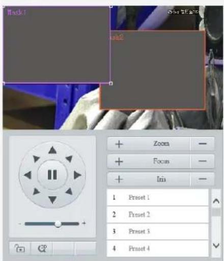

- Select the mask mode, Rectangle or Polygon.
- 2D-mask camera: For a PTZ camera, the privacy mask does not move and zoom with the camera.
- 3D-mask camera: For a PTZ camera, the privacy mask moves and zooms with the camera and the masked area is always covered.
- Add a privacy mask.
(1) Click Add. The privacy mask is a rectangle by default.

natural_image
Close-up of a textured surface with yellow and black lines, no visible text or symbols(2) Adjust the position and size of the mask or draw a mask as needed.
Adjust the position and size of the mask.
- Point to a border of the mask and drag it to the desired position.
- Point to a handle of the mask and drag to resize it.
Draw a mask.
- Polygon: Click on the image and drag to draw a line. Repeat the action to draw more lines to form an enclosed shape as needed. Up to 4 lines are allowed.
- Rectangle: Click on the image and drag to draw a rectangle.
- Set the privacy mask.
| Item | Description |
| Mask style | Select the mask style, Black or Mosaic.NOTE!This parameter is configurable when Mask Mode is set to Rectangle. By default, the mask style of polygon mask is black and cannot be modified.Mosaic is only available on certain models. |
| Max. Zoom (3D-mask camera) | Set the maximum zoom ratio to determine whether to show or hide the privacy mask.If the current lens zoom ratio is less than the maximum zoom ratio, the privacy mask is invalid. |
| Set As Max. (3D-mask camera) | Click to set the current lens zoom ratio as the maximum zoom ratio. |
| Preset (3D-mask camera) | Click to rotate the camera to the masked area (generally, the masked area is in the center of the live video). |
5.5.4 Quick Focus
Fast focus effectively saves focus time and avoids missing important information after the camera changes the scene, focus and zoom.

NOTE!
- This function is only available on certain models.
-
Set the zoom speed to 2 on the Image page when quick focus is enabled.
-
Go to Setup > Image > Quick Focus.
- Select the Enable Quick Focus checkbox to enable it.
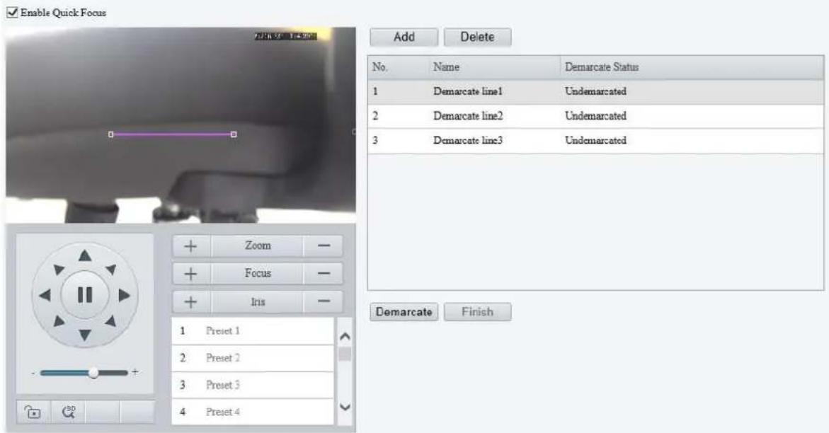
- Add a calibration line for the desired scene.
(1) Click Add. A line displays on the image.
(2) Adjust the position and length of the line or draw a line as needed.
Adjust the position and length of the line.
- Point to the line and drag it to the desired position.
- Point to a handle of the line and drag to resize it.
Draw a line.
Click on the image and drag to draw a line.
- Click Demarcate to start automatic zoom. After the auto zoom is completed, click Finish to complete calibration. If you click Finish during calibration, the calibration line is considered invalid.
- Repeat the above steps to calibrate more scenes. Up to 4 scenes are allowed.
5.6 Smart
On the Smart page, you can select the smart event to be monitored and click ✅ to configure relevant parameters.
The smart events supported by the device and the parameters supported by the events may vary with device model.
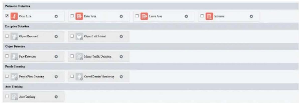
Common Button Description
| Button | Description |
| Create detection rules. Up to 4 detection rules are allowed for each smart event. | |
| Delete detection rules. |

NOTE!
- For dual-channel devices, you can set smart parameters for the channels separately.
- Some smart functions are mutually exclusive. When a smart function is enabled, the functions that are mutually exclusive with it are grayed out.
- For multi-sensor network dome cameras, each of the 4 fixed dome cameras function as independent channels.
➢ Inter-channel: Smart functions are not mutually exclusive.
Intra-channel: Some smart functions are mutually exclusive.
5.6.1 Alarm-triggered Actions
Configure linkage actions to be triggered when an alarm occurs.
Perimeter protection, exception detection, object detection, people flow counting, and auto tracking support alarm-triggered actions (also known as linkage actions).
| Conventional | Alarm Output | Storage |
| √ Alarm the Center□ Send E-mail□ Panoramic Linkage√ Upload Image(Original) | □ A → 1□ A → 2□ Alarm Sound | □ Recording Edge Storage□ Image Edge Storage□ FTP Video Storage |
- Conventional alarm-triggered actions
| Item | Description |
| Upload to FTP | The camera uploads snapshots to the specified FTP server when an alarm occurs.1. Configure FTP and Snapshot.2. Select the Upload to FTP checkbox to enable this function. |
| Send E-mail | The camera sends snapshots to the specified email addresses when an alarm occurs.1. Configure E-mail and Snapshot.2. Select the Send Email checkbox to enable this function. |
| Alarm the Center | The camera uploads alarm information to the surveillance center when an alarm occurs.Select the Alarm the Center checkbox to enable this function. |
| Report Data to Center | The camera uploads data to the server when an alarm occurs.1. Configure management platform.2. Select the Report Data to Center checkbox to enable this function. |
| Metadata Collection | The camera uploads the metadata information collected from the captured object to the server when an alarm occurs.1. Configure MetadataCollection.2. Select the Metadata Collection checkbox to enable this function. |
| Upload Image(Original) | The camera uploads the original snapshot and the cutout image of the captured object to the server when an alarm occurs.Select the Upload Image(Original) checkbox to enable this function.For dual-channel cameras, when this function is configured for channel 2 (thermal channel), it will trigger channel 1 (visible light channel) to capture an image and upload the original image with the cutout image of the captured object to the server. |
| Upload Image(Target) | The camera uploads the cutout image of the captured object to the server.Select the Upload Image(Target) checkbox to enable this function. |
2. Alarm output
| Item | Description |
| Alarm Output | Connect the external alarm output devices, such as alarm lights and alarm bells, etc., to the camera's ALARM OUT interfaces. The camera triggers alarm output devices when an event occurs.A->1: A refers to the ALARM OUT interface on the device, 1 means the first ALARM OUT interface. A->2 means the second ALARM OUT interface on the device, and so on. The number of ALARM OUT interfaces may vary with the device model. See the device datasheet for specifications. 1. Configure Alarm Output.2. Select the Alarm Output checkbox to enable this function. 1. Configure Alarm Output.2. Select the Alarm Output checkbox to enable this function. |
| Alarm Sound | The camera plays warning sounds when an alarm occurs.1. Select the Alarm Sound checkbox, and then click2. Set the arming schedule for audible alarms. See Arming Schedule for details.3. Set the alarm audio content and alarm times.·Audio: Set the audio content to be played when an alarm occurs. See Audio File.·Repeat: Set the number of times the audio to be played when an alarm occurs.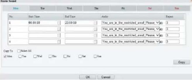 NOTE!This function may vary with device model. NOTE!This function may vary with device model. |
| Flashing Light | The light flashes for a certain period of time when an alarm occurs.1. Select the Flashing Light checkbox, and then click2. Set the flash duration.3. Set the arming schedule. See Arming Schedule for details.NOTE!This function may vary with device model. |
3. Alarm-triggered storage
| Item | Description |
| Recording Edge Storage | The camera saves alarm recordings to its memory card or NAS when an alarm occurs.1. Configure Memory Card or Network Disk.2. Select the Recording Edge Storage checkbox. |
| Image Edge Storage | The camera saves alarm snapshots to its memory card or NAS when an alarm occurs.1. Configure Memory Card or Network Disk.2. Select the Image Edge Storage checkbox. |
| FTP Video Storage | The camera uploads alarm recordings to the specified FTP server when an alarm occurs.1. Configure FTP.2. Select the FTP Video Storage checkbox. |
4. Alarm-triggered PTZ
| Item | Description |
| Trigger Tracking | The camera tracks and zooms on the object that triggered the alarm until the set tracking time is reached or the object disappears.1. Select the Trigger Tracking checkbox.2. Click Tracking to configure tracking parameters. See Tracking for details. |
| Link with Secondary Device | When an alarm is triggered, the secondary device will be linked to track the target.1. Select Link with Secondary Device and click Linkage Parameters.2. Complete the Panoramic Linkage settings. |
| Panoramic Linkage | The camera automatically tracks the object that triggered the alarm.1. Configure panoramic linkage. See Panoramic Linkage for details.2. Select the Panoramic Linkage checkbox. |
| Go to Preset | The camera automatically goes to a preset position when an alarm occurs.1. Select the Go to Preset checkbox.2. Choose the preset to be linked with motion detection alarm. See PTZ for details. |
5.6.2 Arming Schedule
You can set an arming schedule to determine when the camera performs detection.
- Draw a schedule
To set an armed period, click Armed, and then click or drag on the schedule to select the time cells you want to enable arming. To set a disarmed period, click Unarmed, and then click or drag on the schedule to select the time cells you want to disable arming.

- Edit a schedule
Click Edit, set the arming time, and then click OK.


NOTE!
- Up to 4 time periods are allowed per day. The time periods cannot overlap.
• To apply the same time settings to other days, select the desired day(s), and then click Copy.
5.6.3 Smart Service Switch
Configure smart service switch so the camera can automatically switch smart services according to time schedules or linked presets.
- Go to Setup > Smart> Smart Service Switch.

-
Click and choose a switch mode.
-
Timed Switch: Switch to a specified smart service at a set time.
-
Preset Switch: Switch to a specified smart service at a set time specified for a specified preset.
-
Configure the switch mode parameters.
- Timed Switch
| Item | Description |
| Auto Switching | When auto switch is enabled and switching conditions are met, the system switches to the corresponding smart service automatically. The list includes the default service. |
| Schedule | The default service (No.1, by default, unspecified) takes effect when the current time is not within the listed periods. You can add up to 5 periods and assign a smart service for each period. Clickto set time.For certain perimeter protection functions, you can configure overlapping periods, which means, multiple smart services may be effective during the same period.For mutually exclusively smart services which cannot be enabled at the same time, overlapping periods are not allowed, and on-screen messages will appear.When panoramic linkage has been enabled and a specified smart service is mutually exclusive with panoramic linkage, an on-screen message will also appear. |
| Smart Service | Clickto choose smart functions. All the functions on theSmart Servicepage except panoramic linkage are listed in the drop-down list.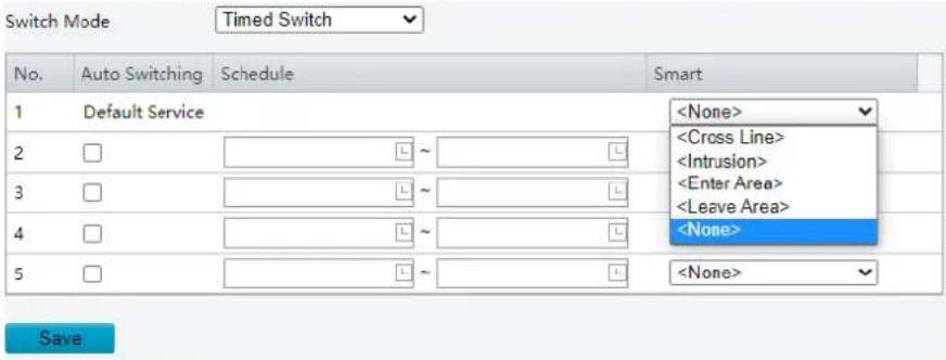 |
- Preset Switch
Click to choose a preset. You can set up to 4 locations and link a location to a preset (the linked presets must be configured in advance, see Preset). The steps for configuring a position are similar to that for configuring timed switch, that is, you can configure 4 locations and 4 corresponding schedules, each schedule includes periods and corresponding smart services.
![Select Channel Channel2 Enable Auto Switch Switch Mode Preset Switch Link Preset Location1 [None] No. Auto Switching Schedule Smart 1 Default Service 2 □ ~ 3 □ ~ 4 □ ~ 5 □ ~ Save](/content/2026/06/1364534/images/8e541d228e61bfb4af05ad34520961fa70e24a5abfd528433ead9cb0a799c850.jpg)
- (Optional) Select the Enable Auto Switch checkbox. After selecting the Enable Auto Switch checkbox, you may still configure or enable/disable smart services.
- Timed Switch
The camera switches to the linked smart service at the start time of a period.
The camera switches to the default service at the end time of a period, or switches to the corresponding smart service at the start time of the next period.
The camera switches smart service at once when Auto Switch is enabled.
- Preset Switch
The camera switches smart service only when calling a linked preset.
The camera checks time when calling a preset. If the current time is within a specified period, the camera switches to the smart service linked to the period.
The camera switches to the default smart service of the preset if the current time is not within any listed periods.
- Click Save.
5.6.4 Cross Line Detection
Cross line detection detects objects crossing a user-specified virtual line in a specified direction. The camera reports an alarm when the detection rule is triggered.
-
Go to Setup > Intelligent > Smart.
-
Select Cross Line and click ⚙ to configure it.
-
Add a detection rule.
(1) Click + to add a detection line. Up to 4 detection rules are allowed.
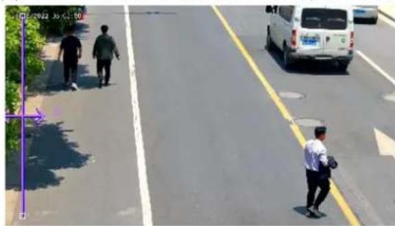
(2) Adjust the position and length of the line or draw a line as needed.
Adjust the position and length of the line.
- Point to the line and drag it to the desired position.
- Point to a handle of the line and drag to resize it.
Draw a line.
Click on the image and drag to draw a line.

NOTE!
When editing detection rules, you can click 🔒 to lock the scene to prevent pan/tilt movement caused by triggered detection rules, and click 🔒 to unlock the scene after you finish editing detection rules.
- Set the detection rule.
| Item | Description | ||
| Trigger Direction | Select the direction from which the object crosses the line to trigger an alarm.A->B: The camera reports a cross line alarm when it detects an object crossing the line from A to B.B->A: The camera reports a cross line alarm when it detects an object crossing the line from B to A.A<->B (default): The camera reports a cross line alarm when it detects an object crossing the line from A to B or from B to A. | ||
| Sensitivity | Set the detection sensitivity.The higher the sensitivity, the more likely cross line behaviors will be detected, and the more likely false alarms will occur. | ||
| Level | Select the priority of the detection rule, includingHigh, Medium, andLow.The camera detects the rule that is triggered first by default. If multiple rules are triggered at the same time, the camera detects the rule with higher priority. | ||
| Detection Object | Select the object to be detected, includingMotor Vehicle, Non-Motor Vehicle, and Pedestrian.Note:Some models only support configuring motor vehicle and pedestrian as the detection objects.The detection objects supported may vary with device model. Please refer to the actual interface. | ||
| Filter Type | After you select a detection object, you can set a filter rule for it.For example, if you have selectedMotor Vehicleas a detection object, selectMotor Vehiclefrom theFilter Typedrop-down list and set theMax. SizeorMin. Sizefor it, then motor vehicles larger than the Max. Size or smaller than the Min. Size will not be detected. | ||
| Max. Size/Min. Size | When enabled, a box appears on the image, you can point to a handle of the box and drag to resize it. The camera filters objects larger than the Max. Size or smaller than the Min. Size. The width and height of the maximum filter area must be greater than that of the minimum filter area.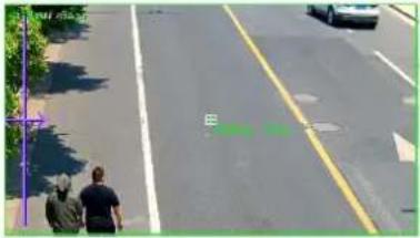  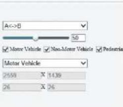 | ||
| Overlay | Bounding Box: SelectOnto add the bounding box ID within the code stream, which is suitable for viewing recordings with a bounding box on a third-party platform.Detection Rule: SelectOnto view the drawn detection rules in video streams. | ||
-
Set the alarm-triggered actions and arming schedule. See Alarm-triggered Actions and Arming Schedule for details.
-
Click Save.
5.6.5 Enter Area Detection
Enter area detection detects objects entering a user-specified area. The camera reports an alarm when the detection rule is triggered.
-
Go to Setup > Intelligent > Smart.
-
Select Enter Area and click ⚙ to configure it.
-
Add a detection rule.
(1) Click + to add a detection area. The detection area is a hexagon by default. Up to 4 detection rules are allowed.

natural_image
Aerial view of two people walking on a paved road lined with yellow painted lines and white pavement, no visible text or symbols.(2) Adjust the position and size of the area or draw an area as needed.
Adjust the position and size of the area.
- Point to a border of the area and drag it to the desired position.
- Point to a handle of the area and drag to resize it.
Draw an area.
Click on the image and drag to draw a line. Repeat the action to draw more lines to form an enclosed shape as needed. Up to 6 lines are allowed.

NOTE!
When editing detection rules, you can click to lock the scene to prevent pan/tilt movement caused by triggered detection rules, and click to unlock the scene after you finish editing detection rules.
- Set the detection rule.
| Item | Description | ||
| Sensitivity | Set the detection sensitivity.The higher the sensitivity, the more likely entry behaviors will be detected, and the more likely false alarms will occur. | ||
| Level | Select the priority of the detection rule, includingHigh, Medium, and Low.The camera detects the rule that is triggered first by default. If multiple rules are triggered at the same time, the camera detects the rule with higher priority. | ||
| Detection Object | Select the object to be detected, includingMotor Vehicle, Non-Motor Vehicle, and Pedestrian.Note:Some models only support configuring motor vehicle and pedestrian as the detection objects.The detection objects supported may vary with device model. Please refer to the actual interface. | ||
| Filter Type | After you select a detection object, you can set a filter rule for it.For example, if you have selectedMotor Vehicleas a detection object, selectMotor Vehicle from theFilter Typedrop-down list and set theMax. Size or Min. Sizefor it, then motor vehicles larger than the Max. Size or smaller than the Min. Size will not be detected. | ||
| Max. Size/Min. Size | When enabled, a box appears on the image, you can point to a handle of the box and drag to resize it. The camera filters objects larger than the Max. Size or smaller than the Min. Size. The width and height of the maximum filter area must be greater than that of the minimum filter area. | ||
 |  | 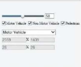 | |
| Overlay | Bounding Box: Select On to add the bounding box ID within the code stream, which is suitable for viewing recordings with a bounding box on a third-party platform.Detection Rule: Select On to view the drawn detection rules in video streams. | ||
-
Set the alarm-triggered actions and arming schedule. See Alarm-triggered Actions and Arming Schedule for details.
-
Click Save.
5.6.6 Leave Area Detection
Leave area detection detects objects leaving a user-specified area. The camera reports an alarm when the detection rule is triggered.
-
Go to Setup > Intelligent > Smart.
-
Select Leave Area and click ⚙ to configure it.
-
Add a detection rule.
(1) Click + to add a detection area. The detection area is a hexagon by default. Up to 4 detection rules are allowed.
(2) Adjust the position and size of the area or draw an area as needed.
Adjust the position and size of the area.
- Point to a border of the area and drag it to the desired position.
- Point to a handle of the area and drag to resize it.
Draw an area.
Click on the image and drag to draw a line. Repeat the action to draw more lines to form an enclosed shape as needed. Up to 6 lines are allowed.
When editing detection rules, you can click 🔒 to lock the scene to prevent pan/tilt movement caused by triggered detection rules, and click 🔒 to unlock the scene after you finish editing detection rules.
- Set the detection rule.
| Item | Description | ||
| Sensitivity | Set the detection sensitivity.The higher the sensitivity, the more likely cross line behaviors will be detected, and the more likely false alarms will occur. | ||
| Level | Select the priority of the detection rule, includingHigh, Medium, and Low.The camera detects the rule that is triggered first by default. If multiple rules are triggered at the same time, the camera detects the rule with higher priority. | ||
| Detection Object | Select the object to be detected, includingMotor Vehicle, Non-Motor Vehicle, and PedestrianNote:Some models only support configuring motor vehicle and pedestrian as the detection objects.The detection objects supported may vary with device model. Please refer to the actual interface. | ||
| Filter Type | After you select a detection object, you can set a filter rule for it.For example, if you have selectedMotor Vehicleas a detection object, selectMotor Vehiclefrom theFilter Typedrop-down list and set theMax. Size or Min. Sizefor it, then motor vehicles larger than the Max. Size or smaller than the Min. Size will not be detected. | ||
| Max. Size/Min. Size | When enabled, a box appears on the image, you can point to a handle of the box and drag to resize it. The camera filters objects larger than the Max. Size or smaller than the Min. Size. The width and height of the maximum filter area must be greater than that of the minimum filter area.   | ||
| Overlay | Bounding Box: SelectOnto add the bounding box ID within the code stream, which is suitable for viewing recordings with a bounding box on a third-party platform.Detection Rule: SelectOnto view the drawn detection rules in video streams. | ||
-
Set the alarm-triggered actions and arming schedule. See Alarm-triggered Actions and Arming Schedule for details.
-
Click Save.
5.6.7 Intrusion Detection
Intrusion detection detects objects entering a user-specified area and staying for a preset time. The camera reports an alarm when the detection rule is triggered.
-
Go to Setup > Intelligent > Smart.
-
Select Intrusion and click ⚙ to configure it.
-
Add a detection rule.
(1) Click + to add a detection area. The detection area is a hexagon by default. Up to 4 detection rules are allowed.
(2) Adjust the position and size of the area or draw an area as needed.
Adjust the position and size of the area.
- Point to a border of the area and drag it to the desired position.
- Point to a handle of the area and drag to resize it.
Draw an area.
Click on the image and drag to draw a line. Repeat the action to draw more lines to form an enclosed shape as needed. Up to 6 lines are allowed.

NOTE!
When editing detection rules, you can click to lock the scene to prevent pan/tilt movement caused by triggered detection rules, and click to unlock the scene after you finish editing detection rules.
- Set the detection rule.
| Item | Description | ||
| Time Threshold(s) | Set how long the object stays in the detection area to trigger an intrusion alarm.If an object stays in the detection area for the set time, an intrusion alarm will be triggered. | ||
| Sensitivity | Set the detection sensitivity.The higher the sensitivity, the more likely intrusion behaviors will be detected, and the more likely false alarms will occur. | ||
| Percentage | The percentage for the area an object occupies within the detection area. Objects smaller than the set percentage will not be detected or trigger an alarm. | ||
| Level | Select the priority of the detection rule.The camera detects the rule that is triggered first by default. If multiple rules are triggered at the same time, the camera detects the rule with higher priority. | ||
| Detection Object | Select the object to be detected, includingMotor Vehicle, Non-Motor Vehicle, and Pedestrian.Note:Some models only support configuring motor vehicle and pedestrian as the detection objects.The detection objects supported may vary with device model. Please refer to the actual interface. | ||
| Filter Type | After you select a detection object, you can set a filter rule for it.For example, if you have selectedMotor Vehicleas a detection object, selectMotor Vehiclefrom theFilter Typedrop-down list and set theMax. SizeorMin. Sizefor it, then motor vehicles larger than the Max. Size or smaller than the Min. Size will not be detected. | ||
| Max. Size/Min. Size | When enabled, a box appears on the image, you can point to a handle of the box and drag to resize it. The camera filters objects larger than the Max. Size or smaller than the Min. Size. The width and height of the maximum filter area must be greater than that of the minimum filter area. | ||
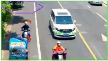 |  | 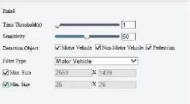 | |
| Overlay | · Bounding Box: Select On to add the bounding box ID within the code stream, which is suitable for viewing recordings with a bounding box on a third-party platform.· Detection Rule: Select On to view the drawn detection rules in video streams. | ||
-
Set the alarm-triggered actions and arming schedule. See Alarm-triggered Actions and Arming Schedule for details.
-
Click Save.
5.6.8 Object Removed Detection
Object removed detection detects objects removed from a user-specified area. The camera reports an alarm when the detection rule is triggered.
-
Go to Setup > Intelligent > Smart.
-
Select Object Removed and click 🔒 to configure it.
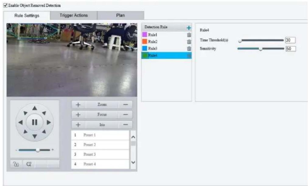
- Add a detection rule.
(1) Click + to add a detection area. The detection area is a hexagon by default. Up to 4 detection rules are allowed.

(2) Adjust the position and size of the area or draw an area as needed.
Adjust the position and size of the area.
- Point to a border of the area and drag it to the desired position.
- Point to a handle of the area and drag to resize it.
Draw an area.
Click on the image and drag to draw a line. Repeat the action to draw more lines to form an enclosed shape as needed. Up to 6 lines are allowed.

NOTE!
When editing detection rules, you can click to lock the scene to prevent pan/tilt movement caused by triggered detection rules, and click to unlock the scene after you finish editing detection rules.
- Set the detection rule.
| Item | Description |
| Time Threshold(s) | Set how long the object is removed from the detection area to trigger an alarm.If an object is removed from the detection area for the set time, an alarm will be triggered. |
| Sensitivity | Set the detection sensitivity.The higher the sensitivity, the more likely object removal behaviors will be detected, and the more likely false alarms will occur. |
-
Set the alarm-triggered actions and arming schedule. See Alarm-triggered Actions and Arming Schedule for details.
-
Click Save.
5.6.9 Object Left Behind Detection
Object left behind detection detects objects left behind in a user-specified area. The camera reports an alarm when the detection rule is triggered.
- Go to Setup > Intelligent > Smart.
- Select Object Left Behind and click ⚙ to configure it.

- Add a detection rule.
(1) Click + to add a detection area. The detection area is a hexagon by default. Up to 4 detection rules are allowed.
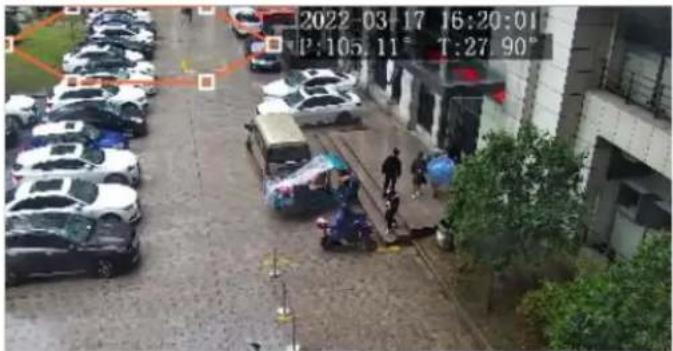
(2) Adjust the position and size of the area or draw an area as needed.
Adjust the position and size of the area.
- Point to a border of the area and drag it to the desired position.
- Point to a handle of the area and drag to resize it.
Draw an area.
Click on the image and drag to draw a line. Repeat the action to draw more lines to form an enclosed shape as needed. Up to 6 lines are allowed.

NOTE!
When editing detection rules, you can click 🔒 to lock the scene to prevent pan/tilt movement caused by triggered detection rules, and click 🔒 to unlock the scene after you finish editing detection rules.
- Set the detection rule.
| Item | Description |
| Time Threshold(s) | Set how long the object is left behind in the detection area to trigger an alarm.If an object is left behind in the detection area for the set time, an alarm will be triggered. |
| Sensitivity | Set the detection sensitivity.The higher the sensitivity, the more likely object left behind behaviors will be detected, and the more likely false alarms will occur. |
- Set the alarm-triggered actions and arming schedule. See Alarm-triggered Actions and Arming Schedule for details.
- Click Save.
5.6.10 Defocus Detection
Defocus detection detects lens defocus. The camera reports an alarm when the detection rule is triggered.
- Go to Setup > Intelligent > Smart.
- Select Defocus and click ⚙ to configure it.
√ Defocus Detection
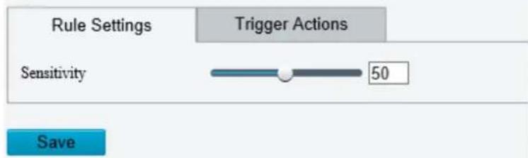
- Set the detection sensitivity. The higher the sensitivity, the more likely defocus will be detected, and the more likely false alarms will occur.
- Set the alarm-triggered actions. See Alarm-triggered Actions for details.
- Click Save.
5.6.11 Scene Change Detection
Scene change detection detects the change of surveillance scene caused by external factors such as intentional camera movement. The camera reports an alarm when the detection rule is triggered.
- Go to Setup > Intelligent > Smart.
- Select Scene Change and click ✅ to configure it.
√ Scene Change Detection

- Set the detection sensitivity. The higher the sensitivity, the more likely scene change behaviors will be detected, and the more likely false alarms will occur.
- Set the alarm-triggered actions and arming schedule. See Alarm-triggered Actions and Arming Schedule for details.
- Click Save.
5.6.12 Face Detection
Face detection detects and captures faces in a specified detection area.
-
Go to Setup > Intelligent > Smart.
-
Select Face Detection and click ⚙ to configure it.
- Set the face detection rule.
| Item | Description |
| Snapshot Area | Select the snapshot area.Full Screen: The camera detects and captures all faces in the live video.Specified Area: The camera only detects and captures faces in a specified area of live video.Select Specified Area and a detection box appears in the left preview window. Adjust the position and size of the area or draw an area as needed.- Adjust the position and size of the area. Point to a border of the area and drag it to the desired position. Point to a handle of the area and drag to resize it.- Draw an area. Click on the image and drag to draw a line. Repeat the action to draw more lines to form an enclosed shape as needed. Up to 6 lines are allowed.NOTE!When editing detection rules, you can clickto lock the scene to prevent pan/tilt movement caused by triggered detection rules, and clickto unlock the scene after you finish editing detection rules. Adjust the position and size of the area or draw an area as needed.- Adjust the position and size of the area. Point to a border of the area and drag it to the desired position. Point to a handle of the area and drag to resize it.- Draw an area. Click on the image and drag to draw a line. Repeat the action to draw more lines to form an enclosed shape as needed. Up to 6 lines are allowed.NOTE!When editing detection rules, you can clickto lock the scene to prevent pan/tilt movement caused by triggered detection rules, and clickto unlock the scene after you finish editing detection rules. |
| Snapshot Sensitivity | Set the snapshot sensitivity.The higher the sensitivity, the more likely a face will be detected. |
| Snapshot Mode | Set the snapshot mode.Intelligent Recognition: The camera continuously performs face detection.Alarm Input: The camera only performs face detection in the event of an alarm input. Before use, you need to enable alarm input and configure arming schedule for it. SeeAlarm Inputfor details. |
| Human Body Snapshot | Select to enable or disable human body snapshot. |
| Min. Pupillary Distance (px) | The minimum distance (unit: pixel) between two pupils. Faces with a pupillary distance smaller than the value will not be captured.To set the minimum pupillary distance, clickDraw, when the cursor shape changes, drag to change the distance; or type a value in the text box directly. |
| Static Object Detection | Choose whether to detect static objects. |
| Overlay | Bounding Box: SelectOnto add the bounding box ID within the code stream, which is suitable for viewing recordings with a bounding box on a third-party platform.Detection Rule: SelectOnto view the drawn detection rules in video streams. |
- Set the face selection rule.
| Item | Description |
| Selection Mode | Select the face selection mode.Effect Priority: The camera selects 1 to 3 snapshots with the best quality to report. You can specify the number of photos to select.Speed Priority: The camera selects certain number of snapshots from the moment that the face is detected tillSelection Timeoutis up. You can specify the number of photos to select.Periodic Selection: The camera selects a snapshot in every selection period. For example, ifSelection Periodis set to 500ms, the camera selects a face snapshot every 500ms, and ifUpload Original Imageis enabled, both the original snapshot containing the face and the face cutout will be uploaded. |
| Number of Selected Photos | Set the number of snapshots to be selected in the range of 1 to 3. This parameter is set to 1 by default and cannot be modified on certain models. |
| Filter by Angle | After you enableFilter by Angleand set the filtering rule, faces with unqualified angles (larger than the set angles) will be filtered during face detection.[IMAGE] |
| Face Deduplication | For scenarios where the face appears several times within the detection rule in a short period of time.ClickOnto enable face deduplication. When enabled, the camera extracts and filters the features from the captured face images, then selects the best quality face image.Deduplication Similarity Threshold: Determine if there is a duplicate face in deduplication library. If the face similarity is higher than the set threshold, the camera will consider there is a duplicate face and will not perform capture.Deduplication Library Quality Threshold: Determine if the face can enter the deduplication library.If the face quality score is higher than the set value, the face can enter the deduplication library.If there is a similar face in the deduplication library, and the face quality score is higher than the similar face quality score in the deduplication library, the similar face will be overwritten.If there is no similar face in the deduplication library, the face automatically enters the deduplication library.If the deduplication library is full, it deletes the earliest face.If the face quality score is equal or lower than the set value, the face cannot enter the deduplication library.Deduplication Library Update Interval(s): Determines if the face(s) in the deduplication library need to be deleted. If the actual retention of the face is higher than the set value, it is deleted automatically.Face DeduplicationOnOffDeduplication Similarity...80Deduplication Library Q...50Deduplication Library U...60 |
- Set the face recognition rule. See Face Recognition for details.

NOTE!
Face recognition cannot be enabled with human body snapshot and face deduplication at the same time.
- Mask undesired areas.
(1) Click + to add a masked area. The masked area is a hexagon by default. Up to 4 masked areas are allowed.


(2) Adjust the position and size of the area or draw an area as needed.
Adjust the position and size of the area.
- Point to a border of the area and drag it to the desired position.
- Point to a handle of the area and drag to resize it.
Draw an area.
Click on the image and drag to draw a line. Repeat the action to draw more lines to form an enclosed shape as needed. Up to 6 lines are allowed.

NOTE!
When editing detection rules, you can click to lock the scene to prevent pan/tilt movement caused by triggered detection rules, and click to unlock the scene after you finish editing detection rules.
7. Set the photo OSD.
Configure OSD that will overlay on images captured from live video.

- Use Live View OSD: Use the OSD that overlays on live video.
- Configure Separately: Configure photo OSD separately (different from live video OSD).
(1) Click behind Font Color and Background Color to set the font color and background color of each image.
(2) Set other parameters as needed.
| Item | Description |
| Overlay Position | Select the position of OSD on the photo.Inside: Overlay inside the image.External Top: Overlay on the top of the image, and the image will be bigger.External Bottom: Overlay on the bottom of the image, and the image will be bigger. |
| Font Size | Choose a font size:X-large, Large, Medium, or Small. You can select the size of the text on the snapshot as needed. This size is relative and will be adjusted automatically depending on the size of the picture. |
| Character Space | Set the distance between the OSD area and the edge of image.Range: 0 to 10px. |
| Show Configuration Item Name | Choose whether to show the configuration item name, such asDate & Time, Device ID, etc. |
| Time Format | Choose a time format: HH:mm:ss, HH:mm:ss.aaa, hh:mm:ss tt, or hh:mm:ss.aaa tt. |
| Date Format | Choose a date format:dd/MM/yyyy, MM/dd/yyyy, etc. |
(3) Set overlay type.
| Item | Description |
| Overlay Area | Customize the X and Y coordinates. Overlay information will be displayed in the corresponding position in the screen.The top left corner of the image is the origin (0, 0), the horizontal axis is the X-axis, and the vertical axis is the Y-axis.This parameter is available only when Overlay Position is set to Inside. |
| Overlay Type | Select the checkbox, the corresponding overlay information will be displayed on the photo. Up to 6 overlay information are allowed.Date&Time: Displays the current date of the device.Device ID: Displays device ID on the photo. The device ID can be set in Setup > System > Device Information.Intersection ID: Displays the intersection information of device's location.Custom 1/2/3: Displays customized contents on the photo. Up to 3 customized overlay information are allowed. |
| Customize Configuration Item Name | Customize the overlay type name. Up to 6 configuration item names can be customized. |
| Overlay Position | Click the drop-down list to select the position of OSD on photo.Select the overlay position, for example, Area 1. You may change the position of the area by entering X and Y coordinates. After saving, the overlay information of Area 1 will be displayed in the corresponding position.Change the overlay area. For example, when change Area 1 to Area 2, the display position of overlay information will also be changed from Area 1 to Area 2. |
| Space Count | Set the number of spaces after the OSD content. Range: 0 to 10. |
| Line Feed Count | Set whether and how to break line(s) for the subsequent configuration items.0: No line break.1: Display the subsequent contents in the second line in the same area.2/3: Display the subsequent contents in the third or fourth line in the same area.NOTE!In External Top or External Bottom mode, if the Line Feed Count is set to 2 or 3, the subsequent configuration items move to the next line.In External Top or External Bottom mode, up to 8 lines can be displayed. The larger the font size, the fewer lines are displayed; the smaller the font size, the more lines are displayed. |
 | Use the two buttons to rearrange the order of configuration items. |
| [HS6V] | Delete an unneeded configuration item. |
(4) Click Save.
- Set the alarm-triggered actions and arming schedule. See Alarm-triggered Actions and Arming Schedule for details.
- Click Save.
5.6.13 Face Recognition
Face recognition compares the faces captured in live view with the faces stored in face libraries, and uploads the comparison results to the server.
- Go to Setup > Intelligent > Smart.
- Select Face Detection and click ⚙️.
- Click the Face Library tab.
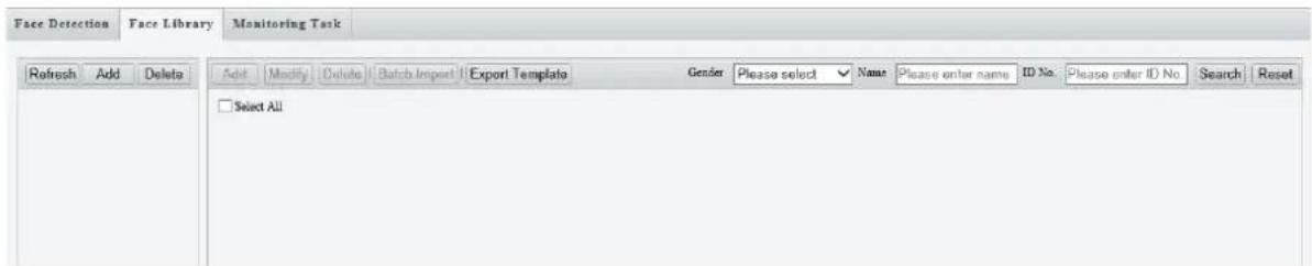
- Create face libraries.
Click Add in the left area, enter the library name, and click OK.
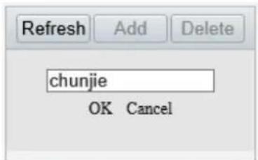
- Add face data.
| Item | Description |
| Add one by one | 1. Click Add.Add Modify Delete Batch Import Export Template Gender Please select Name Please enter name ID No. Please enter ID No. Search Reset2. Upload a face image and complete the required face information.ADD Face InfoNameGender Unidentified Male Female ID Type ID CardID NoFace Library Picture UploadedJPG only. Image size: 30K-300K.OK Cancel ID Type ID CardID NoFace Library Picture UploadedJPG only. Image size: 30K-300K.OK Cancel |
| Add in batches | 1. Click Export Template to export the CSV face template file to the PC.2. Complete the required face data in the template with reference to the import guide. Refer to the import guide to fill in the template with the required face data.3. Click Batch Import, select the CSV file you have edited, and click Upload. |
The imported face data are shown as below:

6. Add monitoring tasks.
Open the Monitoring Task tab.

(1) Click Add.

(2) Complete the monitoring task settings.
| Monitoring Type | Description |
| Monitoring Task | Select to enable or disable the monitoring task. |
| Monitoring Task Name | Enter a name for the monitoring task. |
| Cause of Monitoring | Enter the cause of the monitoring task. |
| Monitoring Type | Select the monitoring type.All: The camera reports an alarm and performs the set alarm-triggered actions once it detects a face.Match Alarm: The camera reports a match alarm and performs the set alarm-triggered actions when the similarity between a captured face and a face in the monitored face library reaches the confidence threshold.Not Match Alarm: The camera reports a not match alarm and performs the set alarm-triggered actions when the similarity between a captured face and a face in the monitored face library fails to reach the confidence threshold. |
| Confidence Threshold | By default, the confidence threshold is set to 80. A match alarm/not match alarm occurs when the similarity between a captured face and a face in the face library reaches/fails to reach the threshold.The higher the value, the more accurate the face recognition. |
(3) Select the face library to be monitored.
(4) Set the alarm-triggered actions and arming schedule. See Alarm-triggered Actions and Arming Schedule for details.
(5) Click OK.
- Click Save.
5.6.14 Human Body Detection
Human body detection detects humans in a specified area. The camera reports an alarm when the detection rule is triggered.
- Go to Setup > Intelligent > Smart.
- Select Human Body Detection and click ⚙ to configure it.
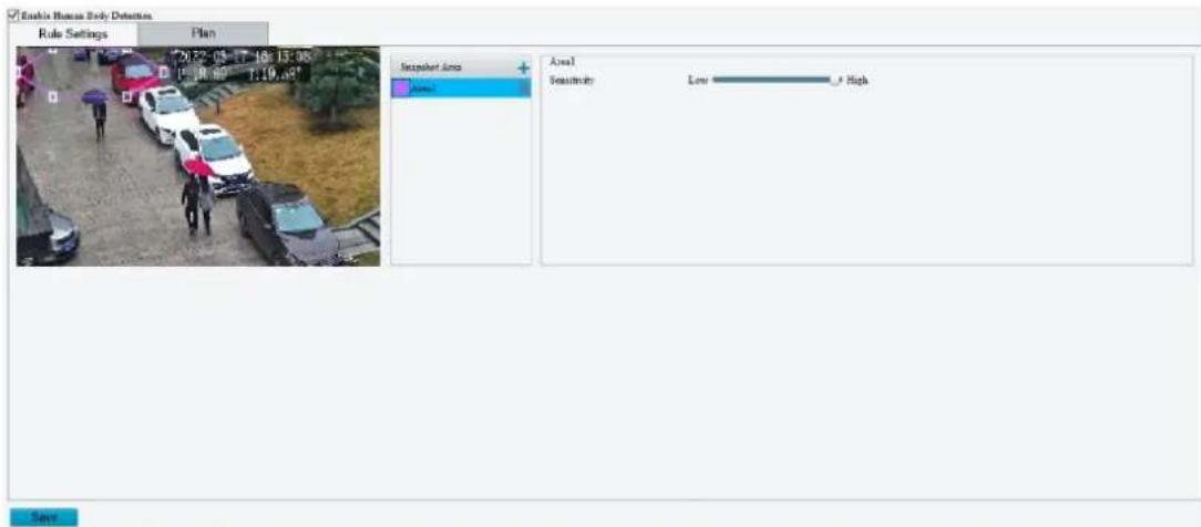
- Add a snapshot area.
(1) Click +. The snapshot area is a hexagon by default. Only one snapshot area is allowed.
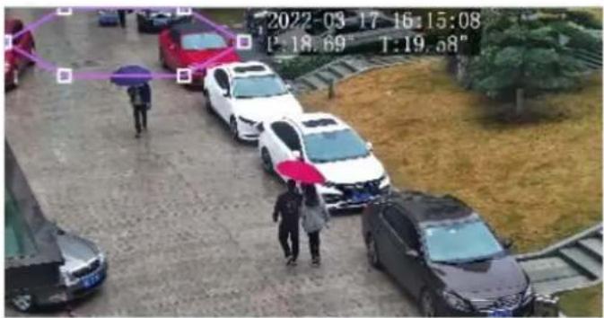
(2) Adjust the position and size of the area or draw an area as needed.
Adjust the position and size of the area.
Point to the area and drag it to the desired position. Drag the corners of the area to resize it.
Draw an area.
Click in the preview window to draw a polygonal area with up to 6 sides.

NOTE!
When editing detection rules, you can click 🔒 to lock the scene to prevent pan/tilt movement caused by triggered detection rules, and click 🔒 to unlock the scene after you finish editing detection rules.
- Set the detection sensitivity. The higher the sensitivity, the more likely humans will be detected, and the more likely false alarms will occur.
- Set the alarm-triggered actions and arming schedule. See Alarm-triggered Actions and Arming Schedule for details.
- Click Save.
5.6.15 Multi-Target Detection
Multi-Target detection detects and captures motor vehicles, non-motor vehicles, and pedestrians in a user-specified area. You can set a multi-target counting OSD to view real-time motor vehicle, non-motor vehicle and pedestrian statistics on the live video. See OSD for details.
- Go to Setup > Intelligent > Smart.
- Select Multi-Target Detection and click 🔍 to configure it.
√ Enable Multi-Target Detection
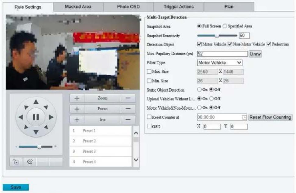
- Set the detection rule.
| Item | Description |
| Snapshot Area | Select the snapshot area.Full Screen: The camera detects and captures objects in the live video.Specified Area: The camera only detects and captures objects in a specified area of live video.Select Specified Area and a detection box appears in the left preview window.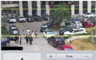 Adjust the position and size of the area or draw an area as needed.- Adjust the position and size of the area. Point to the area and drag it to the desired position. Drag the corners of the area to resize it.- Draw an area. Click in the preview window to draw a polygonal area with up to 6 sides. Select the area you want to monitor.NOTE!When editing detection rules, you can click to lock the scene to prevent pan/tilt movement caused by triggered detection rules, and click to unlock the scene after you finish editing detection rules. Adjust the position and size of the area or draw an area as needed.- Adjust the position and size of the area. Point to the area and drag it to the desired position. Drag the corners of the area to resize it.- Draw an area. Click in the preview window to draw a polygonal area with up to 6 sides. Select the area you want to monitor.NOTE!When editing detection rules, you can click to lock the scene to prevent pan/tilt movement caused by triggered detection rules, and click to unlock the scene after you finish editing detection rules. |
| Snapshot Sensitivity | Set the detection sensitivity.The higher the sensitivity, the more likely objects will be detected, and the more likely false alarms will occur. |
| Detection Object | Select the object to be detected, includingMotor Vehicle, Non-Motor Vehicle, and Pedestrian. |
| Min. Pupillary Distance(px) | The minimum pupillary distance between two pupils. The device will detect faces in live view according to this value. Faces with pupillary distance smaller than the value will not be captured.ClickDraw. Point to a handle of the line and drag it to adjust the length. |
| Filter Type | After you select a detection object, you can set a filter rule for it.For example, if you have selectedMotor Vehicleas a detection object, selectMotor Vehicle from theFilter Typedrop-down list and set theMax. SizeorMin. Sizefor it, then motor vehicles larger than the Max. Size or smaller than the Min. Size will not be detected. |
| Max. Size/Min. Size | When enabled, a box appears on the image, you can point to a handle of the box and drag to resize it. The camera filters objects larger than the Max. Size or smaller than the Min. Size. The width and height of the maximum filter area must be greater than that of the minimum filter area. 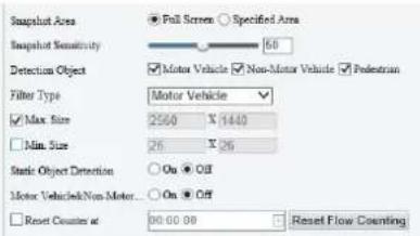 |
| Static Object Detection | Select whether to detect static objects. |
| Upload Vehicles Without License Plates | On: Supports uploading snapshots without license plate information.Off: Only snapshots with license plate information can be uploaded. |
| Motor Vehicle&Non-Motor Vehicle&Pedestrian Count | Select whether to count motor vehicles, non-motor vehicles and pedestrians. |
| Reset Counter at | You can set a time for the camera to clear the traffic statistics or clickReset Flow Counting to clear immediately. |
| OSD | Adjust the OSD position: Specify the exact position of the OSD by entering the X and Y coordinates. The top left corner of the image is the origin (0,0), the horizontal axis is the X-axis, and the vertical axis is the Y-axis.Note:Drag the overlay area on the live view window will change its X/Y value correspondingly. |
4. Mask undesired areas.
(1) Click + to add a masked area. The masked area is a hexagon by default. Up to 4 masked areas are allowed.


(2) Adjust the position and size of the area or draw an area as needed.
Adjust the position and size of the area.
Point to the area and drag it to the desired position. Drag the corners of the area to resize it.
Draw an area.
Click in the preview window to draw a polygonal area with up to 6 sides.

NOTE!
When editing detection rules, you can click to lock the scene to prevent pan/tilt movement caused by triggered detection rules, and click to unlock the scene after you finish editing detection rules.
5. Set photo OSD.
Go to the Photo OSD tab. Set the overlay information that will be displayed on the snapshots captured by the camera.

(1) Select the OSD configuration mode.
Use Live View OSD: Use the OSD that overlays on live video.
Configure Separately: Configure photo OSD separately (different from live view OSD).
(2) Set the overlay position.
Inside: Overlay inside the image.
External Top: Overlay on the top of the image, and the image will be bigger.
External Bottom: Overlay on the bottom of the image, and the image will be bigger.
(3) Set the target type and overlay parameters.
Target types include Motor Vehicle, Non-Motor Vehicle, Pedestrian, and Face. You can set overlay parameters for each target type separately.

NOTE!
Face refers to the face targets in Motor Vehicle, Non-Motor Vehicle, and Pedestrian scenes. For example: In Motor Vehicle scene, the faces of the driver and front passenger are targets.
| Item | Description |
| Specify the exact position of the OSD by entering the X and Y coordinates.The top left corner of the image is the origin (0, 0), the horizontal axis is the X-axis, and the vertical axis is the Y-axis.NOTE!You can also drag an OSD to the desired position: point to the OSD box in the preview window, and drag when the cursor shape changes. | |
| Overlay OSD content | Select the checkbox, and the corresponding overlay information will be displayed on the photo. Up to 14 overlay information are allowed.The overlay content options are based on the metadata collected (see Metadata Collection) for each target type. The options supported may vary with device model. Please refer to the actual interface.Examples of common overlay contents:Time: Displays the device time on the photo.Device No.: Displays device number on the photo.Intersection Info: Displays the intersection information of device's location.Custom 1/2/3: Displays customized contents on the photo. Up to 3 customized overlay information are allowed.Plate Type: Displays the license plate type on the photo.Note:Location, camera ID, device number, and intersection information can be retrieved in Setup > System > Device Info. See details in Device Information. |
| Custom Configuration Item Name | Enter a custom configuration item name, which can replace the display name of the overlay OSD content. |
| Area | Click the drop-down list to select the position of OSD.Select the overlay position, for example, Area 1. You may change the position of the area by entering X and Y coordinates. After saving, the overlay information of Area 1 will be displayed in the corresponding position.Change the overlay area. For example, when change Area 1 to Area 2, the display position of overlay information will also be changed from Area 1 to Area 2. |
| Space Count | Set the number of spaces after the OSD content. Range: 0 to 10. |
| Line Feed Count | Set whether and how to break line(s) for the subsequent configuration items. Range: 0 to 3.0: No line break.1: Displays the subsequent contents in the second line in the same area.2/3: Displays the subsequent contents in the third or fourth line in the same area.Note:In External Top or External Bottom mode, if the Line Feed Count is set to 2 or 3, the subsequent configuration items move to the next line.In External Top or External Bottom mode, up to 8 lines can be displayed. |
| Use the two buttons to rearrange the order of configuration items. | |
| Delete an unneeded configuration item. |
(4) Set the display style.
| Item | Description |
| Font Size | Choose a font size as needed:X-large, Large, Medium, or Small. The font size is relative and will be adjusted automatically depending on the size of the photo. |
| Character Space | Set the distance between the OSD area and the edge of image.Range: 0-10 px. |
| Font Color/Background Color | Click to choose a font color and background color. |
| Show Configuration Item Name | Choose whether to show the configuration item name, such as Date & Time, Device ID, etc.Take Date & Time as an example, if selected, Data & Time: yyyy-MM-dd will be displayed; if unselected, yyyy-MM-dd will be displayed. |
| Time Format | Choose a time format from the drop-down list:HH:mm:ss, HH:mm:ss.aaa, hh:mm:ss tt, or hh:mm:ss.aaa tt |
| Date Format | Choose a date format from the drop-down list: yyyy-MM-dd, Mm-dd-yyyy, yyyy-MM-dd, etc. |
(5) Click Save.
-
Set the alarm-triggered actions and arming schedule. See Alarm-triggered Actions and Arming Schedule for details.
-
Click Save.
5.6.16 Traffic Monitoring /ANPR
1. Traffic Monitoring
The traffic monitoring function can capture motor vehicles, motorcycles, non-motor vehicles, and pedestrians on the roads or in parks, and can identify and monitor specific vehicles, specific license plates, etc.

NOTE!
- Enabling or disabling the traffic monitoring function will restart the device.
-
The actual rule settings, trigger actions, and monitoring plan may vary with device model. Please refer to the actual interface.
-
Go to Setup > Intelligent > Smart.
- Select Enable Traffic Monitoring, and the device will restart.
- After the device restarts, re-enter the Smart page, and click to go to the Traffic Monitoring page.

- Select the number of lanes from the drop-down list. Up to 4 lanes are allowed.
- Select the Lane1/2/3/4 tab to draw the corresponding detection rules. Draw tripwires and lane lines as needed. The device takes a snapshot when the detected target crosses the tripwire.
(1) Click Draw Detection Rules.
(2) Click on the tripwire/lane line.
(3) Point to a handle of the tripwire/lane line and drag it to adjust the length and direction. Point to any position of the tripwire/lane line and drag it to the desired position.
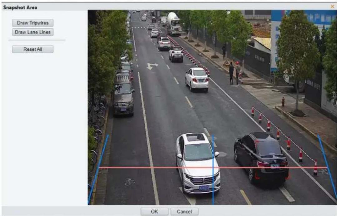
(4) (Optional) Click Reset All to clear all and draw again.
(5) Click OK.
- Set the traffic monitoring rules.
| Item | Description |
| High/Low Pole | Traffic monitoring needs to choose to install on the high/low pole according to the application scenarios. SelectHigh Pole/Low Polefrom the drop-down list as needed.High Pole: Mainly used in 3-6m scenes. Supports capturing motor vehicles, non-motor vehicles, and pedestrians.Low Pole: Mainly used in 1-3m scenes. Supports capturing vehicle license plates. |
| Upload Vehicles Without License Plates | On: Supports uploading snapshots without license plate information.Off: Only snapshots with license plate information can be uploaded. |
| Lane ID | Enter an integer in the range of 1 to 254. |
| Lane Description | Enter the lane description with 0-24 characters. |
| Vehicle Head Only | Set whether to capture vehicle head only. |
| Detection Type | Select the detection type(s) as needed: Motor Vehicle, Non-Motor Vehicle, and Pedestrian. |
| Clear Flow Statistics | Select theReset Counteratcheckbox and set a time for the camera to clear people counting statistics on the OSD.To clear now, clickClear. |
| OSD | Adjust the OSD position: Specify the exact position of the OSD by entering the X and Y coordinates. The top left corner of the image is the origin (0,0), the horizontal axis is the X-axis, and the vertical axis is the Y-axis.Note:Drag the overlay area on the live view window will change the X/Y value correspondingly. |
| Video Source | View live videos and snapshots.Local Video: SelectLocal Videoto view the live videos. You may clickPauseto pause the video as needed.Photo Directory: SelectPhoto Directoryto view the photo directory. ClickBrowseto select a path to view snapshots.ClickNextto view cached snapshots. |
- Set the arming schedule. See Arming Schedule for details.
- Click Save.
2. ANPR
The ANPR (Automatic Number Plate Recognition) function can capture motor vehicles, motorcycles, non-motor vehicles, and pedestrians on the roads or in parks, and can identify and monitor specific vehicles, specific license plates, etc.

NOTE!
- Enabling or disabling the ANPR function will restart the device.
-
The actual rule settings, trigger actions, and monitoring plan may vary with device model. Please refer to the actual interface.
-
Go to Setup > Intelligent > Smart.
- Select ANPR, and the device will restart.
- After the device restarts, re-enter the Smart page, and click 🔒 to go to ANPR page.

- Select the number of lanes from the drop-down list. Up to 4 lanes are allowed.
- Select the Lane1/2/3/4 tab to draw the corresponding detection rules. Draw tripwires and lane lines as needed. The device takes a snapshot when the detected target crosses the tripwire.
(1) Click Draw Detection Rules.
(2) Click on the tripwire/lane line.
(3) Point to a handle of the tripwire/lane line and drag it to adjust the length and direction. Point to any position of the tripwire/lane line and drag it to the desired position.
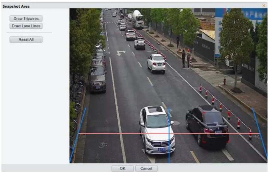
(4) (Optional) Click Reset All to clear all and draw again.
(5) Click OK to save the detection rules.
- Set the ANPR rules.
| Item | Description |
| High/Low Pole | ANPR function needs to choose to install the high/low pole according to the application scenarios. Select High Pole/Low Pole from the drop-down list as needed.High Pole: Mainly used in 3-6m scenes. Supports capturing motor vehicles, non-motor vehicles, and pedestrians.Low Pole: Mainly used in 1-3m scenes. Supports capturing vehicle license plates. |
| Upload Vehicles Without License Plates | On: Supports uploading snapshots without license plate information.Off: Only snapshots with license plate information can be uploaded. |
| Country/Region | Select ALL or a specific country or region to detect all license plate types (letters+digits) or plates of a certain country or region. |
| Lane ID | Enter an integer in the range of 1 to 254. |
| Lane Description | Enter the lane description with 0-24 characters. |
| Vehicle Head Only | Set whether to capture vehicle head only. |
| Detection Type | Select the detection type(s) as needed: Motor Vehicle, Motorcycle, Non-Motor Vehicle, and Pedestrian.Note:For some device models, ifMotorcycleis selected, the non-motor vehicles are processed as motor vehicle. |
| Clear Flow Statistics | Select theReset Counter atcheckbox and set a time for the camera to clear people counting statistics on the OSD.To clear now, clickClear. |
| OSD | Adjust the OSD position: Specify the exact position of the OSD by entering the X and Y coordinates. The top left corner of the image is the origin (0,0), the horizontal axis is the X-axis, and the vertical axis is the Y-axis.Note:Drag the overlay area on the live view window will change its X/Y value correspondingly. |
| Video Source | View live videos and snapshots.Local Video: SelectLocal Videoto view the live videos. You may clickPauseto pause the video as needed.Photo Directory: SelectPhoto Directoryto view the photo directory. ClickBrowseto select a path to view snapshots.ClickNextto view cached snapshots. |
-
Set the alarm-triggered actions and arming schedule. See Alarm-triggered Actions and Arming Schedule for details.
-
Click Save.
3. Snapshot Handling
Snapshot handling can process the captured snapshots, especially for motor vehicle close-up images.
- Go to Setup > Intelligent > Smart > Traffic Monitoring / ANPR > Snapshot Handling.
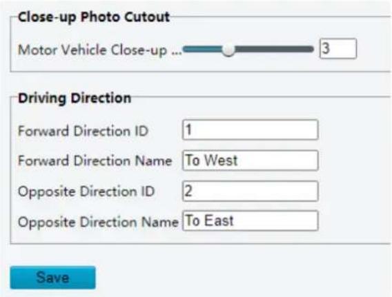
- Drag the slider to set the motor vehicle close-up photo cutout range. Range: 1-7. The larger the range, the smaller the motor vehicle in the close-up image.
- Set the driving direction, which can be displayed as a photo OSD on ANPR snapshots.
- (Optional) Devices support radar function can configure Vehicle Track to view the vehicle movement track in radar's Web interface.
- Click Save.
4. Photo OSD
On Screen Display (OSD) is the characters displayed on live videos and snapshots, for example, date, time, people counting statistics, and zoom.
- Go to Setup > Intelligent > Smart > ANPR > Photo OSD.
- Select the OSD configuration mode.
- Use Live View OSD: Use the OSD that overlays on live video.
- Configure Separately: Configure photo OSD separately (different from live view OSD).
- Click next to Font Color and Background Color to set the font color and background color of the overlay information on image.
- Set parameters for the single photo of passing.
| Item | Description |
| Overlay Position | Select the position of OSD on the photo.Inside: Overlay inside the image.External Top: Overlay on the top of the image, and the image will be bigger.External Bottom: Overlay on the bottom of the image, and the image will be bigger. |
| Font Size | Choose a font size as needed:X-large, Large, Medium, or Small. The font size is relative and will be adjusted automatically depending on the size of the photo. |
| Character Space | Set the distance between the OSD area and the edge of image.Range: 0-10 px. |
| Show Configuration Item Name | Choose whether to show the configuration item name, such as Date & Time, Device ID, etc. |
| Passing Close-up OSD | When select Passing Close-up OSD, the snapshot will be zoomed in. You can selecClose-up Photo OSDto configure the OSD to be overlaid on the close-up photo, e.g., Date & Time, Device ID, etc. |
| Close-up Photo OSD | Select the OSD overlay mode from the drop-down list.Selected OSD: Configure the close-up photo OSD separately.Copy Single Photo of Violation OSD: Use the OSD that overlays on the single photo of passing. |
| Time Format | Choose a time format from the drop-down list:HH:mm:ss, HH:mm:ss.aaa, hh:mm:ss tt, or hh:mm:ss.aaa tt |
| Date Format | Choose a date format from the drop-down list: yyyy-MM-dd, Mm-dd-yyyy, yyyy-MM-dd, etc. |
- Set the overlay type(s). Overlay items should be configured with corresponding intelligent service snapshot handling or metadata collection.
| Item | Description |
| Overlay Type | Select the checkbox, and the corresponding overlay information will be displayed on the photo. Up to 14 overlay information are allowed.Time: Displays the device time on the photo.Location: Displays the device location on the photo.Direction: Displays the lane direction on the photo. See details in Snapshot HandlingDevice No.: Displays device number on the photo.Lane: Displays the lane on the photo.Camera ID: Displays the camera ID on the photo.Plate Number: Displays the license plate number on the photo.Motor Vehicle/Non-Motor Vehicle/Pedestrian Flow: Displays the real-time motor vehicle/non-motor vehicle/pedestrian flow.Intersection Info: Displays the intersection information of device's location.Custom 1/2/3: Displays customized contents on the photo. Up to 3 customized overlay information are allowed.Plate Type: Displays the license plate type on the photo.Note:Location, camera ID, device number, and intersection information can be retrieved in Setup > System > Device Info. See details in Device Information. |
| CustomizeConfiguration Item Name | Customize the overlay type name. Up to 14 configuration item names can be customized. |
| Overlay Position | Click the drop-down list to select the position of OSD.Select the overlay position, for example, Area 1. You may change the position of the area by entering X and Y coordinates. After saving, the overlay information of Area 1 will be displayed in the corresponding position.Change the overlay area. For example, when change Area 1 to Area 2, the display position of overlay information will also be changed from Area 1 to Area 2. |
| Space Count | Set the number of spaces after the OSD content. Range: 0 to 10. |
| Line Feed Count | Set whether and how to break line(s) for the subsequent configuration items. Range: 0 to 3.0: No line break.1: Displays the subsequent contents in the second line in the same area.2/3: Displays the subsequent contents in the third or fourth line in the same area.Note:In External Top or External Bottom mode, if the Line Feed Count is set to 2 or 3, the subsequent configuration items move to the next line.In External Top or External Bottom mode, up to 8 lines can be displayed. |
| Use the two buttons to rearrange the order of configuration items. | |
| Delete an unneeded configuration item. |
- Click Save.
5.6.17 Heat Map
Detect the heat flow of people in different areas and integrate with the back-end platform to display the heat map in different colors.
NOTE!
- Only some device models support heat map configuration. This function is mainly used with the back-end platform. Please refer to the actual device.
- Depending on the device capability, the linkage method (report data to center) of the heat map will only be displayed to supported devices.
1. Go to Setup > Intelligent > Smart.
2. Select Heat Map and click 🔒. A page as shown below appears.
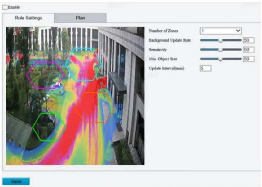
3. Set the detection rules.
| Item | Description |
| Number of Zones | Select the number of zones (1-4) from the drop-down list. The left live view page displays the default detection box. Adjust the position and size of the detection area as needed.To adjust the position of the detection area, point to a border of the area and drag it to the desired position.To adjust the size of the detection area, point to a handle of the box and drag to resize it.To redraw the detection area, click on the image and drag to draw a line. Repeat the action to draw more lines to form an enclosed shape as needed. 3-6 lines are allowed.Note:When editing detection rules, you can click [IMAGE] to lock the scene to prevent pan/tilt movement caused by triggered detection rules, and click [IMAGE] to unlock the scene after you finish editing detection rules. Adjust the position and size of the detection area as needed.To adjust the position of the detection area, point to a border of the area and drag it to the desired position.To adjust the size of the detection area, point to a handle of the box and drag to resize it.To redraw the detection area, click on the image and drag to draw a line. Repeat the action to draw more lines to form an enclosed shape as needed. 3-6 lines are allowed.Note:When editing detection rules, you can click [IMAGE] to lock the scene to prevent pan/tilt movement caused by triggered detection rules, and click [IMAGE] to unlock the scene after you finish editing detection rules. |
| Background Update Rate | Drag the slider to adjust the background update speed.The greater the value, the faster the background updates. |
| Sensitivity | Drag the slider to adjust the detection sensitivity.The higher the sensitivity, the more likely small motions will be detected, and the more likely false alarms will occur. Set based on the scene and your actual needs. |
| Min. Object Size | Drag the slider to adjust the minimum object size.The greater the value, the more small objects will be filtered. |
| Update Interval (min) | Set the update interval of the heat map. |
-
Set the arming schedule. See Arming Schedule for details.
-
Click Save.
5.6.18 People Flow Counting
People flow counting counts people passing a tripwire, including the number of people that have entered, left, and the total.
- Go to Setup > Intelligent > Smart.
- Select the People Flow Counting checkbox, and click 🔒 to configure it.
- A tripwire is displayed in the left preview window. Adjust the position and size of the tripwire as needed or draw a new one. Only one tripwire is allowed.
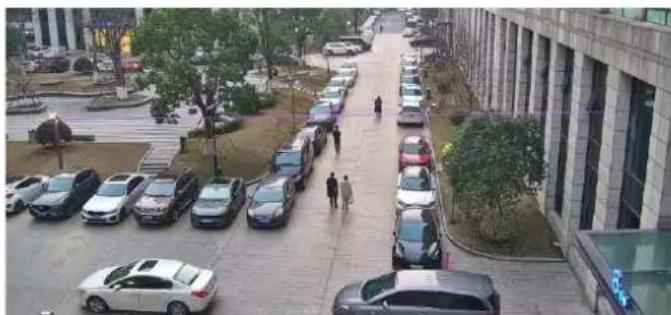
natural_image
Aerial view of a multi-lane residential street with parked cars and pedestrians, no visible text or signage.- Adjust the position and size of the tripwire, or draw a new tripwire:
Click the tripwire, point to an endpoint, and drag to change the length and direction.
Point to the tripwire and drag it to the desired position.
Click on the image and drag to draw a new tripwire.
- Draw a detection area on the image. The default detection area is the full screen. You can draw a polygon. Make sure the tripwire is inside the polygon; otherwise, counting will fail.
Point to a handle of the detection area and drag to change its size and direction.
Point to a border of the detection area and drag it to the desired position.
Click and drag on the image to draw a line. Repeat the action to draw more lines to form an enclosed shape as needed. Up to 6 lines are allowed.

NOTE!
When editing detection rules, you can click to lock the scene to prevent pan/tilt movement caused by triggered detection rules, and click to unlock the scene after you finish editing detection rules.

natural_image
Close-up of a white surface with purple measurement lines and arrows, no readable text or symbols present.- Set counting rules.
| Item | Description |
| Data Report Interval(s) | Set a time interval for the camera to send people flow statistics to the server. You need to configure a server to receive the statistics.Default: 60. Range: 1 to 60. |
| Reset Counter at | Select the Reset Counter at checkbox and set a time for the camera to clear people counting statistics on the OSD.To clear now, click Clear.NOTE!Only OSD statistics will be reset; it does not reset people flow statistics reported to the server. |
| Enter | Choose an entry direction:A- >B: From A to B.B- >A: From B to A. |
| Counting Type | Choose a counting type to display real-time statistics on live video.You need to configure a people counting OSD first. See OSD for details.Total: Displays the total number of people entering and leaving the area.People Entered: Displays the number of people entering the area.People Exited: Displays the number of people leaving the area. |
| People Present Alarm | Set thresholds for triggering people present minor/major/critical alarm. An alarm is triggered when the number of people present reaches a set threshold.Range: 1 to 180.Minor Alarm: Threshold for triggering a people present minor alarm.Major Alarm: Threshold for triggering a people present major alarm. The value must be greater than that of minor alarm.Critical Alarm: Threshold for triggering a people present critical alarm. The value must be greater than that of major alarm.NOTEThe range supported may vary with camera model. |
| Overlay | Bounding Box: Select On to add the bounding box ID within the code stream, which is suitable for viewing recordings with a bounding box on a third-party platform.Detection Rule: Select On to view the drawn detection rules in video streams. |
- Set the alarm-triggered actions and arming schedule. See Alarm-triggered Actions and Arming Schedule for details.
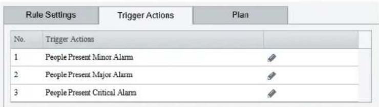
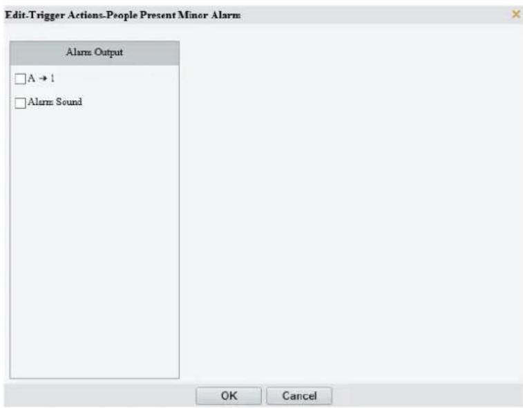
- Click Save.
5.6.19 Crowd Density Monitoring
Crowd density monitoring monitors the number of people in a specified area and triggers an alarm if the number exceeds the set alarm threshold.
- Go to Setup > Intelligent > Smart.
- Select Crowd Density Monitoring and click ⚙ to configure it.
- A detection box is displayed in the left preview window by default. You can adjust the position and size of it or draw an area as needed. Only one area is allowed.
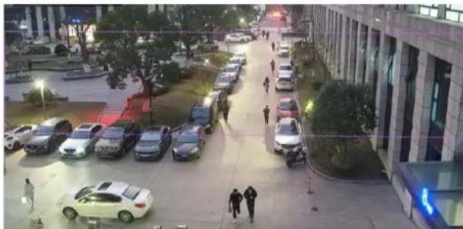
natural_image
Night street scene with parked cars and pedestrians, no visible text or signage- Adjust the position and size of the area.
Point to the area and drag it to the desired position. Drag the corners of the area to resize it.
- Draw an area.
Click in the preview window to draw a polygonal area with up to 6 sides.

NOTE!
When editing detection rules, you can click 📄 to lock the scene to prevent pan/tilt movement caused by triggered detection rules, and click 🔒 to unlock the scene after you finish editing detection rules.
- Set the crowd density monitoring rule.
| Item | Description |
| Report Interval(s) | Set the time interval for reporting crowd density statistics.Default: 60.Range: 1 to 60.For example, if the interval is set to 60, the camera will report crowd density statistics to the server every 60 seconds. |
| OSD | Adjust the OSD position: Specify the exact position of the OSD by entering the X and Y coordinates. The top left corner of the image is the origin (0,0), the horizontal axis is the X-axis, and the vertical axis is the Y-axis.Note:Drag the overlay area on the live view window will change its X/Y value correspondingly. |
| People Present Alarm | Set the crowd density alarm threshold. When the number of people in the specified area reaches a set threshold, an alarm is triggered.Minor Alarm: A minor alarm is triggered when the number of people in the specified area reaches the set value.Major Alarm: A major alarm is triggered when the number of people in the specified area reaches the set value. The value of major alarm must be greater than that of minor alarm.Critical Alarm: A critical alarm is triggered when the number of people in the specified area reaches the set value. The value of critical alarm must be greater than that of major alarm. |
| Overlay | Bounding Box: Select On to add the bounding box ID within the code stream, which is suitable for viewing recordings with a bounding box on a third-party platform.Detection Rule: Select On to view the drawn detection rules in video streams. |
- Set the alarm-triggered actions and arming schedule. See Alarm-triggered Actions and Arming Schedule for details.


NOTE!
The rules supported may vary with device model. Please refer to the actual interface.
- Click Save.
5.6.20 Auto Tracking
The camera can automatically track objects that trigger the predefined tracking rule.
- Go to Setup > Intelligent > Smart.
- Select Auto Tracking and click ⚙ to configure it.
- Set the tracking rule.
| Item | Description |
| Tracking Object | Select the object to be tracked, includingMotor Vehicle, Non-Motor Vehicle, and Pedestrian. Note:The objects supported may vary with device model. Please refer to the actual interface. |
| Filter Type | After you select a detection object, you can set a filter rule for it.For example, if you have selectedMotor Vehicleas a detection object, selectMotor Vehicle from theFilter Typedrop-down list and set theMax. Size or Min. Sizefor it, then motor vehicles larger than the Max. Size or smaller than the Min. Size will not be detected. |
| Max. Size/Min. Size | When enabled, a box appears on the image, you can point to a handle of the box and drag to resize it. The camera filters objects larger than the Max. Size or smaller than the Min. Size. The width and height of the maximum filter area must be greater than that of the minimum filter area. |
| Tracking | Click to set tracking parameters. SeeTrackingfor details. |
| Overlay | Bounding Box: SelectOnto add the bounding box ID within the code stream, which is suitable for viewing recordings with a bounding box on a third-party platform.Detection Rule: SelectOnto view the drawn detection rules in video streams. |
- Set the alarm-triggered actions and arming schedule. See Alarm-triggered Actions and Arming Schedule for details.
- Click Save.
5.6.21 Smoke and Fire Detection
Smoke and fire detection detects smoke and fire in the visible light channel and triggers an alarm. The camera uploads the original snapshots triggered by smoke and fire alarms by default.
- Go to Setup > Intelligent > Smart.
- Select Smoke and Fire Detection and click 🔗 to configure it.

-
Set the detection rule.
-
Bounding Box Overlay: A rectangular box is used to frame the object that triggers the detection rule for you to quickly locate it.
- Sensitivity: Set the detection sensitivity. The higher the sensitivity, the more likely smoke and fire will be detected, and the more likely false alarms will occur.
- Simulate Alarm: Simulate fire or fire and smoke to quickly trigger detection rules, improving the connection testing efficiency.
- Shield Area: Shield areas that may interfere with detection or trigger false alarms. A total of 64 shielding areas are allowed, with a maximum of 8 shielding areas per image.
(1) Move the camera to the desired position manually or using presets.
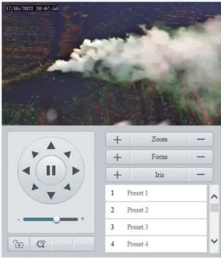
(2) Click Add.
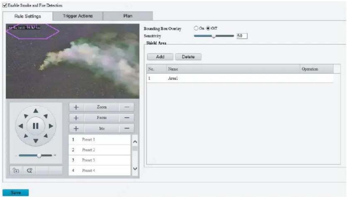
(3) Adjust the position and size of the area or draw an area as needed.
Adjust the position and size of the area. Point to the area and drag it to the desired position. Drag the corners of the area to resize it.
Draw an area. Click in the preview window to draw a polygonal area with up to 6 sides.
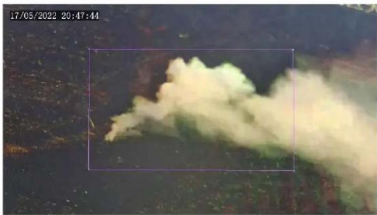
natural_image
Aerial view of a large smoke plume in a dark, forested area, captured at 20:47:44 on 17/05/2022 (no visible text or symbols)
NOTE!
When editing detection rules, you can click 🔒 to lock the scene to prevent pan/tilt movement caused by triggered detection rules, and click 🔒 to unlock the scene after you finish editing detection rules.
| Item | Description |
| Preset | Click to move the shielding area to the center of the image.For example:Area 1 in the figure below is set as a shielding area. |
 After you click Preset, the shielding area is moved to the center of the image. After you click Preset, the shielding area is moved to the center of the image. | |
 NOTE!The area box does not move with the shielding area. NOTE!The area box does not move with the shielding area. | |
| Delete | Delete the shielding area. |
-
Set the alarm-triggered actions and arming schedule. See Alarm-triggered Actions and Arming Schedule for details.
-
Click Save.
5.6.22 Metadata Collection
For dual-channel cameras, you can configure metadata collection parameters for the channels separately.
1. Collect Metadata
Configure metadata collection rules to collect desired metadata information of the monitored objects.
- Go to Setup > Intelligent > Metadata Collection.
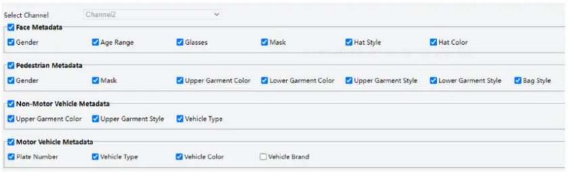
-
Select the metadata to be collected.
-
Click Save.
-
Monitor by Metadata
-
Go to Setup > Intelligent > Metadata Collection > Monitor by Metadata.
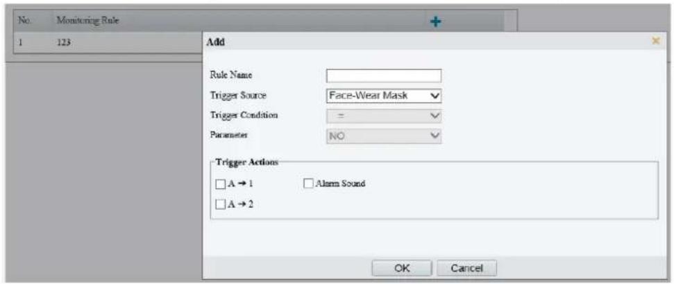
-
Click to add a monitoring rule.
-
Set the monitoring rule.
| Item | Description |
| Rule Name | Set a name for the rule. |
| Trigger Source | Choose the metadata to trigger monitoring:Face-Wear Mask or Face-Body Temperature. |
| Trigger Actions | SeeAlarm-triggered Actionsfor details. |
- Click OK.
5.6.23 Advanced Settings
Advanced settings include snapshot clarity and detection mode for smart functions.
1. Photo
- Go to Setup > Intelligent > Advanced Settings > Photo Parameters.
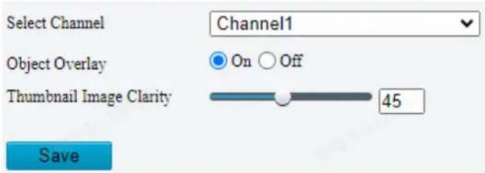
- Select a channel for configuration.
- Select to enable or disable object overlay on the image. When enabled, a bounding box will overlay on the object in the original image.
- Drag the slider or input a number to set the thumbnail image clarity. Please disable Face Detection before setting the photo parameters.
- Click Save.
2. Detection
-
Go to Setup > Intelligent > Advanced Settings > Detection Parameters.
-
Set the detection parameters.
| Item | Description |
| Sync Intelligent Mark with Video | When enabled, intelligent marks (bounding boxes) will follow the detected objects (motor vehicle/non-motor vehicle/pedestrian/face) on live video images.NOTE!Before you enable Sync Intelligent Mark with Video, you need to complete the configuration of Metadata Collection first (see Metadata Collection). |
- Click Save.
3. Tracking
- Go to Setup > Intelligent > Advanced Settings > Tracking.
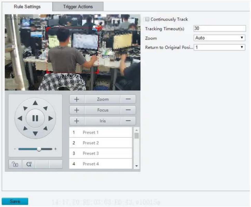
- Set the tracking parameters.
| Item | Description |
| Continuously Track | When enabled, the camera continuously tracks the object that triggers the tracking rule until the object disappears. |
| Tracking Timeout(s) | Set the tracking time. When the set time is reached, the camera stops tracking.NOTE!This parameter is not configurable when Continuously Track is enabled.If the object disappears within the set time, the actual tracking time is the time from the appearance to the disappearance of the object. |
| Zoom | Select the tracking zoom ratio.Auto: The camera automatically adjusts the zoom ratio according to the object distance during tracking.Current Zoom: The camera keeps the current zoom ratio during tracking. |
| Return to Original Position(s) | Set the return to original position time after the tracking target disappears. Range: 1s~10s, the default is 1s.For example, if the time is set to 5s, after the last tracking target disappears for 5s, the camera returns to the original position. |
5.6.24 Panoramic Linkage
Panoramic linkage includes drag-to-zoom, click-to-link, tracking, and face snapshot functions. You need to calibrate on the panoramic and closeup images first (see Calibration) and then configure linkage (see Configure Linkage).
1. Calibration
Calibrate in closeup image and panoramic image to ensure accurate panoramic linkage.
- Go to Setup > Intelligent > Panoramic Linkage.
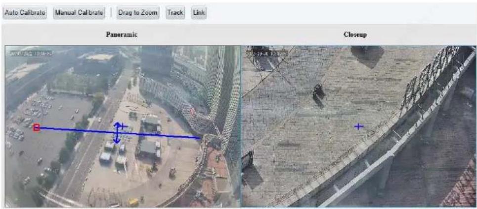

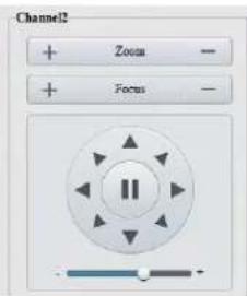
2. Choose a calibration mode.

NOTE!
- The calibration is valid in the current scene. After you switch the scene, you need to calibrate again.
- Multi-channel device supports Single Scene Calibration. To calibrate multiple scenes, select the corresponding lens number to operate in sequence.
Auto Calibration: The system automatically calibrates after user manually calibrates the center of panoramic image and closeup image.
Manual Calibration: User manually calibrates 5-12 times by choosing reference objects on the images.
You may also use manual calibration to fine-tune after an automatic calibration.

NOTE!
Before calibration, click to unlock the primary device. Then, you can adjust the primary device's position within a limited time.
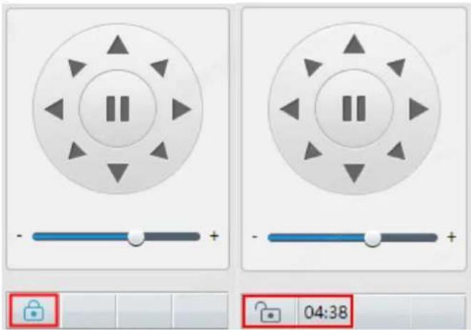
- Auto Calibrate
(1) Click Auto Calibrate.
(2) The system calibrates automatically.
| Item | Description |
| Auto Calibrate | 1. Calibrate image center manually: Click Auto Calibrate, click on the closeup image to move the crosshair + till it points to the same position as the crosshair + on the panoramic image, click Finish Calibration.2. Click Next, click One-Click Calibrate to start automatic calibration. |
| Exit | Click Exit to quit calibration. |
| Finish | Click Finish to finish calibration. After automatic calibration succeeded, the scene status shows green. |
| Re-calibrate | You can click Exit to calibrate again. The scene status shows red if the calibration failed. |

- Manual Calibrate
(1) Click Manual Calibrate.
(2) Calibrate manually.
| Item | Description |
| Exit | Quit calibration without saving the current calibration results; restore the previous calibration results. |
| Finish | Finish calibration and return to the Calibration page. |
| Add | Add a calibration point. |
| Delete | Delete a calibration point. |
| Edit | Edit a calibration point. |
| Clear | Clear all the calibration points on the current page. For certain devices, you need to clear calibration points page by page. |
(3) Calibration on a single calibration page is as follows:
a Click Add. On the left-side panoramic image, click on the target calibration area. A small white block appears as you click, and the area is magnified, allowing you to fine-tune the position of the calibration point. To calibrate on other areas on the image, click Exit to return to the panoramic image and calibrate again.
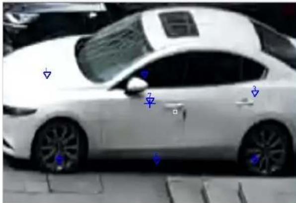
b On the closeup image, find the point that you have marked on the panoramic image, click till the zoom ratio reaches the maximum, adjust the position of the calibration point (small white block) on the panoramic image till it overlaps with the crosshair on the closeup image, and click Calibrate.
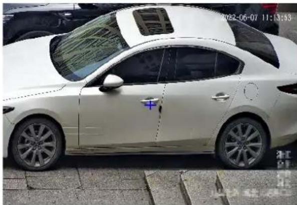
natural_image
Side view of a white sedan parked on a paved street, with no visible text or symbols on the car or background.c Repeat the above two steps to calibrate other points. Depending on the scene, you may need to calibrate 5-12 times. Click Finish when you complete. Certain devices may require multiple such calibration procedures.
2. Configure Linkage
- Drag to zoom
Draw a detection box on the panoramic image. The corresponding area will be magnified on the closeup image to show details.
(1) Go to Setup > Intelligent > Panoramic Linkage.
(2) Select Enable Panoramic Linkage.
(3) Click Save.
(4) Go to Setup > Intelligent > Panoramic Linkage.
(5) Click Drag to Zoom. A rectangle detection area appears on the left-side panoramic image.
(6) Adjust the position and size of the detection area or draw a new one as needed.
➢ Point to a handle (vertex) of the rectangle and drag to resize the detection area.
➢ Point to a border of the rectangle and drag the detection area to the desired position.
Click on the image and drag to draw a new detection area.
The right-side close-up image shows the magnified image of the detection area.

- Click to link
Click anywhere on the panoramic image, the closeup image shows the clicked point at the image center.
(1) Go to Setup > Intelligent > Panoramic Linkage.
(2) Select Enable Panoramic Linkage.
(3) Click Save.
(4) Go to Setup > Intelligent > Panoramic Linkage.
(5) Click Link. When you click anywhere on the panoramic image, the closeup image will zoom in on the clicked point at the center of the image. Click Cancel to deactivate this function.
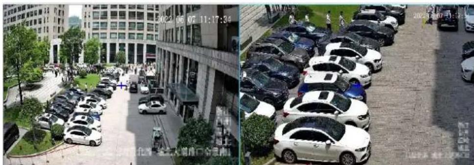
natural_image
Two aerial photos showing a commercial building and a row of parked cars in an urban plaza, with no visible text or signage.- Track mode
This feature is used with perimeter protection.
(1) Go to Setup > Intelligent > Panoramic Linkage.
(2) Select Enable Panoramic Linkage.
√ Enable Panoramic Linkage
Operating Mode
Mode
Track Mode ▼
PTZ Camera
Zoom Coefficient
5
Tracking
□ Continuously Track
Tracking Duration(s)
3
Save
(3) Set track parameters.
| Item | Description |
| Operating Mode | Choose Track Mode from the drop-down list. When an object triggers perimeter protection rules, the PTZ camera will be triggered to track the object and give a closeup of the tracked object till the set tracking duration expires or the object disappears. If the PTZ camera supports mixed traffic detection, you may configure track & snapshot. See Alarm-triggered Actions and Storage.·Auto Track: The camera chooses an object that triggered detection rules.·Manual Track: User chooses motor vehicles, non-motor vehicles, and pedestrians. After the camera detects an object, you can click Track on the Calibration page and choose a bounding box to zoom in on and track the selected object.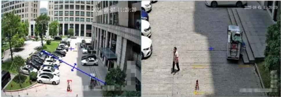 |
| PTZ Camera | ·PTZ Camera IP Address: IP address of the PTZ camera.·HTTP port: The default is 80.·Zoom Coefficient: Enter a coefficient. The greater the coefficient, the greater the zoom ratio of the PTZ camera.NOTE!For certain models it's unnecessary to configure PTZ Camera IP Address and HTTP Port. |
| Tracking | ·Select the Continuously Track checkbox.·Set tracking duration. The tracking stops when the set duration expires or when the object disappears. |
(4) Click Save.
5.7 Alarm
Configure the alarm function, so the camera can report alarms when an event occurs. Configure alarm linkage, so the camera can trigger other devices to perform specified actions when an event occurs.

NOTE!
The supported alarms and linkage actions (or trigger actions) may vary with camera model.
5.7.1 Thermal Imaging Alarm
1. Fire Detection
Fire detection detects fire or heat in the environment and triggers an alarm according to the configured policy.
- Go to Setup > Events > Thermal Alarm > Fire Detection. The page displayed may vary with device model.
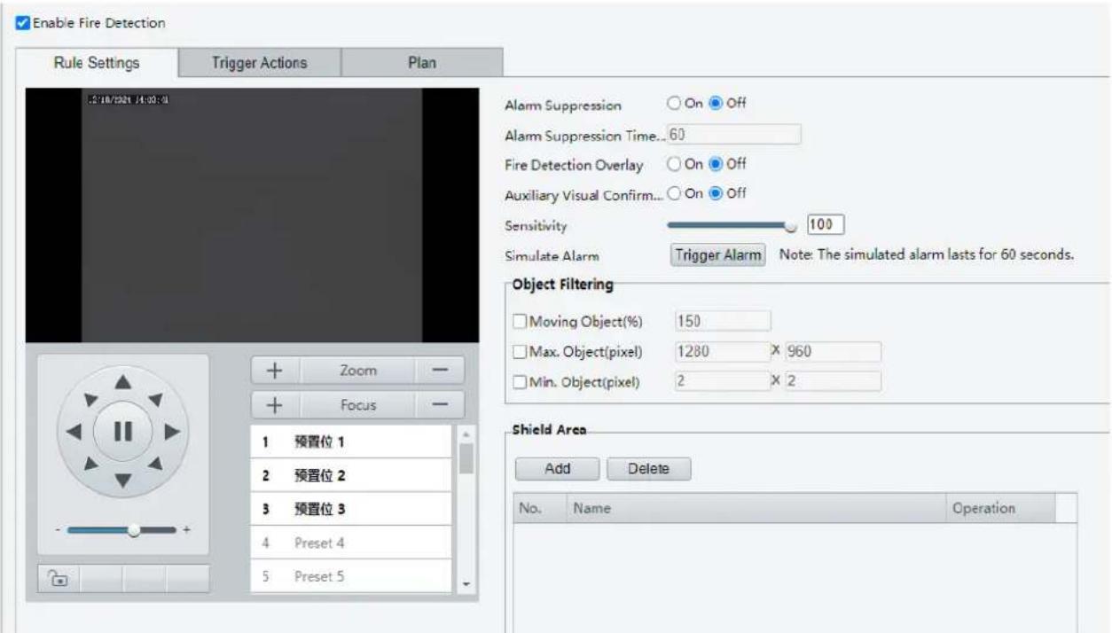
- Set detection rules.
| Item | Description | |
| Detection Mode | Choose a detection mode: Fire Detection or Smoking Detection. | |
| Fire Detection Overlay | When enabled, object bounding boxes will be added to video streams. This feature is applicable to viewing recorded videos showing object bounding boxes on a third-party platform. | |
| Auxiliary Visual Confirmation | When enabled, smoke and fire detection will assist in fire detection to make detection results more accurate. After fire detection detects a fire point, smoke and fire detection will detect smoke around the fire point. A fire alarm will be reported if smoke is detected.NOTE!When this feature is enabled, will other smart functions except smoke and fire detection will be unavailable.This feature is effective only in daytime. | |
| Sensitivity | Drag the slider to adjust detection sensitivity.The higher the sensitivity, the model likely fire and heat will be detected, and the more likely false alarms will occur. The specific value should be determined according to the actual scene or test. | |
| Simulate Alarm | Simulate fire or fire and smoke quickly trigger detection rules, improving the connection testing efficiency. | |
| Fire Alarm Suppression | When enabled, fire detection will not report the same fire point repeatedly within a certain length of time. | |
| Fire Alarm Suppression Time (min) | Enter an integer in the range of 00.NOTE!Fire detection will not report the detected fire point again within the set time. | |
| Object Filtering | Object filtering is intended to reduce false fire alarms by allowing user to specify the movement speed and the maximum and minimum sizes of detected fire points. This feature is disabled by default. To use this feature, select the checkboxes and input appropriate values.Object FilteringMoving Object(%)15Max. Object(pixel)125X2Min. Object(pixel)1X1 | |



natural_image
Blank white image with no visible content, text, or symbols

- Moving Object(%): Enter an integer in the range of 10-1000. The detected object will be filtered if the changed position of the object reaches the set value.
- Max. Object(pixel): The default value is the maximum size to detect. Objects whose size exceeds the set value will be filtered.
- Min. Object(pixel): The default is 2*2. Objects whose size is less than the set value will be filtered.
NOTE!
The camera may falsely detect car windows or static reflective objects as fire points due to their high temperatures caused by sunlight. For example, Moving Object is set to 150%, the object is a car that is 1m long. Fire detection detects fire once per second, totally 3 times. If the vehicle's movement distance is greater than or equal to 1.5 meters in any of the three detections, then the ratio of the car movement distance to the car length is greater than or equal to 150%, then the object will not be considered a fire point and will be filtered. See the diagram below.
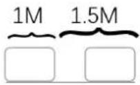
3. Set Shield Area.
Set shield areas to prevent false alarms caused by high-temperature objects in other areas on the image.and totally 64 are allowed on different images.
(1) Rotate the camera to the shield area. You may use presets to quickly rotate the camera to the intended direction.
(2) Click Add. A shield area appears in the upper left corner of the image.
(3) Drag it to the intended position or draw a new one. Repeat the step if necessary.
To adjust the size of the detection area, point to a handle of the box and drag to resize it. To adjust the position of the detection area, point to a border of the area and drag it to the desired position.
To redraw the detection area, click on the image and drag to draw a line. Repeat the action to draw more lines to form an enclosed shape as needed. 3-6 lines are allowed.
| Item | Description |
| Preset | Click the button, the camera will rotate to display the shield area at the center of the image. |
| Delete | Delete a shield area. |

NOTE!
When editing detection rules, you can click to lock the scene to prevent pan/tilt movement cause by triggered detection rules, and click to unlock the scene after you finish editing detection rules.
- Set alarm linkage and an arming schedule.
Go to the Trigger Actions page to set alarm linkage. Go to the Plan page to set an arming schedule. See Alarm-triggered Actions and Arming Schedule for more information.
- Click Save.
2. Temperature Detection
Temperature detection detects the temperature of objects in a specified area and triggers an alarm if the temperature exceeds the set alarm threshold. The camera reports an alarm according to the configured policy.

NOTE!
• This function is only available for thermal imaging cameras.
- The function may vary with camera models.
1. Go to Setup > Alarm > Thermal Alarm > Temperature Detection.

2. Select Enable Temperature Detection.
3. Set temperature parameters.
| Parameter | Description |
| Temperature Unit | Select the temperature unit, including Celsius(°C) and Fahrenheit(°F). |
| Show Temperature Gradient Bar | When enabled, the temperature gradient bar appears on right of the live video, and user can observe the temperature more intuitively. |
| Tracking Highest&Lowest Temperature | When enabled, the highest and lowest temperature will be shown as a red and blue spot respectively that moves with temperature changes. |
| Overlay Temperature on Video | When enabled, temperature information will overlay on the original video (including live videos and recordings). |
| Overlay Temperature on Snapshot | When enabled, temperature information will overlay on snapshots. |
| Temperature Position on Snapshot | Select the temperature position on snapshot, including Around Detection Area and Upper Left Corner of Image. |
4. Set the detection rule. Up to 12 detection rules are allowed.

NOTE!
The detection rule type cannot be changed after it is set.
(1) Click +, add a temperature detection rule. A detection area is displayed in the left preview window by default. To draw a detection point or a detection line, select Point or Line from the drop-down box.
(2) Adjust the detection area, point or line as needed.
(3) Set temperature detection parameters.
- Set the temperature comparison rule.

NOTE!
- Up to 6 temperature comparison rules are allowed.
• Hover over ⚙ to view the details of the set rule.
(1) Click


(2) Set the alarm rule.
Example: If the alarm threshold is set to 100^ C, with the measurement accuracy of 2^ C, and the duration of 3 seconds, the camera will take snapshots and report an alarm when the temperature exceeds 102^ C for 3 seconds.

NOTE!
Please set the alarm threshold within the valid temperature measurement range.
(3) Click OK.
- Set alarm linkage and an arming schedule. See Alarm-triggered Actions and Arming Schedule for details.
- Click Save.
5.7.2 Common Alarm
1. Motion Detection

NOTE!

-
The icon appears in the upper right corner of the image when a motion detection alarm occurs.
• The function may vary with device model. -
Go to Setup > Events > Common Alarm.
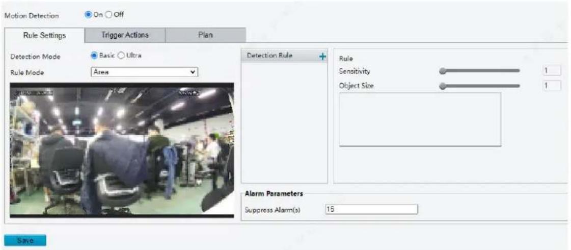
-
Choose the detection mode, including basic mode and ultra mode.
-
Basic: Only moving objects in the specified areas or grids will be detected.
- Ultra: Objects (motor vehicle, non-motor vehicle, and pedestrian) in the specified areas in the ultra mode and moving objects in the basic mode will both be detected.
Basic Mode
The camera detects motions in specified detection areas or grids on the image and will take snapshots and report an alarm when detection rules are triggered.
- Detection area
(1) To add a detection area, click +, then a rectangle appears on the image. Up to four detection areas are allowed.
natural_image
Street scene with parked cars and trees, no visible text or symbols(2) Adjust the position, size and shape of the rectangle detection area, or draw a new one.
Point to a border of the area and drag it to the desired position.
Point to a handle of the area and drag to resize it.
Click anywhere on the image, and then drag to draw a new area.
(3) Set detection rules.
| Item | • Description |
| Sensitivity | Drag the slider to adjust detection sensitivity.The higher the sensitivity level, the higher the detection rate of small motions, and the higher the false alarm rate. Set based on the scene and your actual needs. |
| Object size | Drag the slider to set object size.Object size: The ratio of the size of the detected object to the size of the detection area. An alarm is triggered when the ratio reaches the set value. To detect motion of small objects, you need to draw a small detection area separately.Motion detection results of the current detection area are shown below in real time. The red means motions that have triggered a motion detection alarm. The height of the lines indicates the extent of motion. The density of the line indicates the frequency of motion. The higher a line, the greater the extent. The denser the lines, the higher the frequency. |
(4) Set Suppress Alarm to avoid receiving the same alarms within a certain length of time (alarm suppression time). For example, alarm suppression time is set to 5s, after an alarm is reported:
If no motion is detected within the next 5s, new alarms can be reported after 5s when the alarm suppression time (5s) is over.
If motion is detected within the next 5s, the alarm suppression time recounts from the time of the last alarm, and new alarms can be reported when the alarm suppressions time (5s) is over.
- Grid detection

(1) Set grid detection areas (covered by grid).
(2) Edit detection areas as needed.
Click or drag on grid areas to erase grids.
➢ Click or drag on blank areas to draw grids.
(3) Drag the slider to adjust detection sensitivity.
The higher the sensitivity level, the higher the detection rate of small motions, and the higher the false alarm rate. Set based on the scene and your actual needs.
(4) Set Suppress Alarm to avoid receiving the same alarms within a certain length of time (alarm suppression time). For example, alarm suppression time is set to 5s, after an alarm is reported:
If no motion is detected within the next 5s, new alarms can be reported after 5s when the alarm suppression time (5s) is over. If motion is detected within the next 5s, the alarm suppression time recounts from the time of the last alarm, and new alarms can be reported when the alarm suppression time (5s) is over.
-
Set alarm linkage and an arming schedule. See Alarm-triggered Actions and Arming Schedule for details.
-
Click Save.
Ultra Mode
The camera detects motions of motor vehicles, non-motor vehicles and pedestrians in specified detection areas and will take snapshots and report an alarm when detection rules are triggered.

- Set detection rules.
(1) To add a detection area, click +, then a rectangle appears on the image. Up to four detection areas are allowed.
(2) Adjust the position, size and shape of the rectangle detection area, or draw a new one.
Point to a border of the area and drag it to the desired position.
Point to a handle of the area and drag to resize it.
Click anywhere on the image, and then drag to draw a new area.
(3) Drag the slider to adjust detection sensitivity.
The higher the sensitivity level, the higher the detection rate of small motions, and the higher the false alarm rate. Set based on the scene and your actual needs.
(4) Select the detection object.
- Set alarm linkage and an arming schedule. See Alarm-triggered Actions and Arming Schedule for details.
- Click Save.
2. Tampering Detection
The camera triggers a tampering alarm after the lens is blocked for a certain length of time.
- Go to Setup > Events > Common Alarm > Tampering Detection.
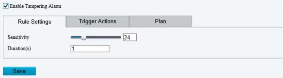
-
Select Enable Tampering Detection.
-
Set detection rules.
(1) Drag the slider to adjust detection sensitivity. The higher the sensitivity level, the higher the detection rate, and the higher the false alarm rate. Set based on the scene and your actual needs.
(2) Set the duration of lens blocking. The camera reports an alarm when the duration of lens blocking exceeds the set value. Set based on the scene and your actual needs.
- Set alarm linkage and an arming schedule. See Alarm-triggered Actions and Arming Schedule for details.
- Click Save.
3. Audio Detection
The camera monitors input audio signals and triggers an audio detection alarm when an exception is detected. Make sure an audio collection device (e.g. sound pickup) is connected, and audio detection is enabled (see Audio).
- When audio input mode is Line/Mic.
- Go to Setup > Events > Common Alarm > Audio Detection.

- Enable Audio Detection.
- Set audio detection rules.
| Item | Description |
| Detection Type | Sudden Rise: Detects sudden rising sound volume, and triggers an alarm when the rise of volume exceeds the difference.Sudden Fall: Detects sudden falling sound volume, and triggers an alarm when the fall of volume exceeds the difference.Sudden Change: Detects sudden rising and falling sound volume, and triggers an alarm when the rise or fall of volume exceeds the difference.Threshold: Triggers an alarm when the volume exceeds the threshold. |
| Difference/Threshold | Difference: The difference between two sound volumes. The camera triggers an alarm when the rise or fall of volume exceeds the difference (range: 0-400). This parameter is applicable when the detection type is Sudden Rise, Sudden Fall, or Sudden Change.Threshold: The camera triggers an alarm when the sound volume exceeds the threshold (range: 0-400). This parameter is applicable when the detection type is Threshold. |
| Diagram of relative audio intensity | Audio detection results are displayed and updated in real time. You can control the display progress by clicking the Start/Stop button.The scales are used to measure sound volume. Gray indicates relative sound intensity. Red means sound volume that has triggered alarms.  |
-
Set alarm linkage and an arming schedule. See Alarm-triggered Actions and Arming Schedule for details.
-
Click Save.
4. Alarm Input
The camera can receive alarms from external third-party devices such as infrared detectors, smoke detectors, etc. After alarm input is configured, the third-party device can send signals to the camera after an event occurs.
- Go to Setup > Events > Common Alarm > Alarm Input.
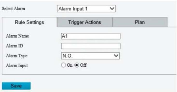
- Choose an alarm input from the drop-down list.
The number of alarm inputs available may vary with camera model. For example, if the camera has two alarm inputs on the tail cable, you can configure alarm input 1 and alarm input 2 separately.
- Configure alarm input.
| Item | Description |
| Alarm Name | The default name is the alarm input channel ID. You rename it as needed. |
| Alarm ID | Set an alarm ID as you need. |
| Alarm Type | Set the alarm type according to the alarm input device.If the alarm input device is normally open (N.O.), choose N.C..If the alarm input device is normally closed (N.C.), choose N.O.. |
| Alarm Input | Click On to enable Alarm Input. |
-
Set alarm linkage and an arming schedule. See Alarm-triggered Actions and Arming Schedule for details.
-
Click Save.
-
Alarm Output
The camera can output alarms to external third-party devices such as alarm bell, buzzer, etc. After alarm output is configured, the camera can output alarm signals when an alarm (such as motion detection alarm, tamping alarm) occurs and trigger the third-party device to perform certain actions.
- Go to Setup > Events > Common Alarm > Alarm Output.

-
Choose an alarm output from the drop-down list. The number of alarm outputs available may vary with camera model.
-
Configure alarm output parameters.
| Item | Description |
| Alarm Name | The default name is the alarm output channel ID. You can rename it as needed. |
| Default Status | Choose the default status. The default is N.O..If the external alarm device is normally open (N.O.), choose N.O..If the external alarm device is normally closed (N.C.), choose N.C.. |
| Delay(s) | The duration of alarm output after the alarm is triggered. Set it as needed. |
| Relay Mode | The default is Monostable.Monostable: The circuit can only remain in one stable state. When a trigger pulse is applied, the circuit switches to another state, and then automatically switches back to the original stable state. The circuit will repeat the same actions when the next trigger pulse arrives.Bistable: The circuit can remain in two stable states. When a trigger pulse is applied, the circuit switches to another state, and remains in this state after the trigger pulse is removed. When the next trigger pulse is applied, the circuit switches back to the other stable state and remains in that state.NOTE!Set relay mode to better adapt to third-party alarm devices such as alarm lights. Please set the relay mode according to the trigger mode of the third-party alarm device. |
- On the Output Schedule page, select Enable Plan, and then set when the camera can output alarms. -
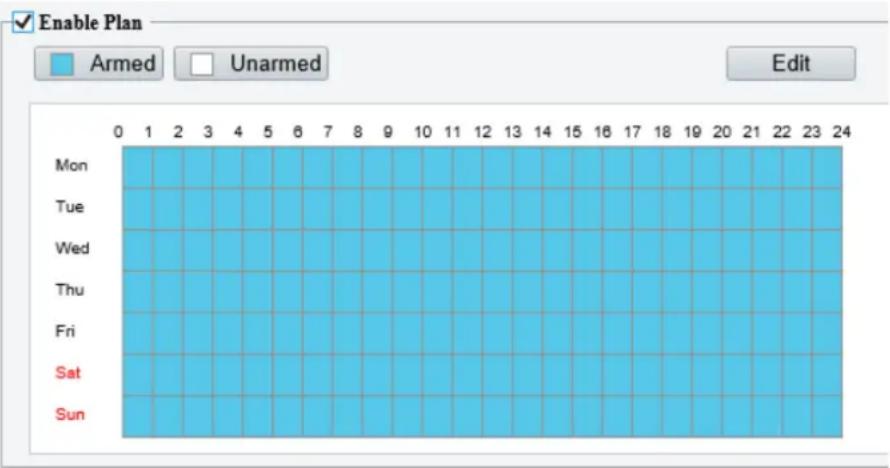
Two methods are available to make an arming schedule:
- Draw a schedule
Click Armed, and then drag on the calendar to set when the camera can output alarms. Click Unarmed, and then drag on the calendar to set when the camera cannot output alarms.
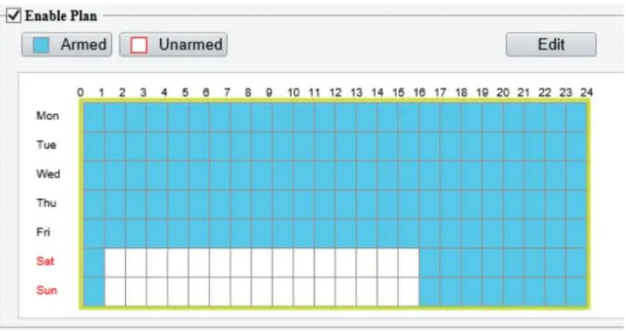
bar
| Day | Armed | Unarmed | |---|---|---| | Mon | 0 | 0 | | Tue | 1 | 0 | | Wed | 2 | 0 | | Thu | 3 | 0 | | Fri | 4 | 0 | | Sat | 5 | 0 | | Sun | 6 | 0 | Edit- Edit the schedule
Click Edit, set a refined schedule, click OK.


NOTE!
- Four periods are allowed each day. The periods must not overlap.
- To apply the current settings to other days, select the checkbox for the days one by one or select the Select All checkbox, and then click Copy.
5. Click Save.

CAUTION!
- Strictly follow the instructions below when powering on external alarm devices (e.g., alarm light) to avoid device damage.
- Check that Alarm Type is set to Normally Open (default) on the camera. Make sure the camera and the external alarm device are disconnected from power.
- After you connect the alarm device to the camera, connect the alarm device to power first, and then connect the camera to power.
6. Event Linkage
Configure event linkage rules on the IPC side so when a specified alarm occurs on a third-party platform, IPC can perform linkage actions such as taking snapshots and reporting alarm.
- Go to Setup > Alarm > Common Alarm > Event Linkage.

- Select an event type.
- Custom the event name and event code.
- Select On next to Event to enable event linkage. This option is disabled by default.
- Set the alarm-triggered actions and arming schedule. See Alarm-triggered Actions and Arming Schedule for details.
- Click Save.
5.7.3 One-key Disarming
The camera cannot trigger linked actions when disarmed.
- Go to Setup > Events > One-key Disarming.
- Choose a disarming mode.
-
Disarm by Schedule: Disarm according to a weekly schedule.
• Disarm Once: Disarm during a specified time period. -
Configure disarming schedule or time according to the disarming mode you chose. The disarming schedule or time applies to all the actions selected.
- Disarm by schedule: Click ⚙ to configure disarming time.

- Disarm Once: Set the disarming time.

-
Choose actions to be disarmed. The actual actions available, for example, for example, alarm light, alarm sound, email, alarm output, may vary with camera model and version.
-
Click Save.
5.8 Storage
Go to Setup > Storage > Storage.
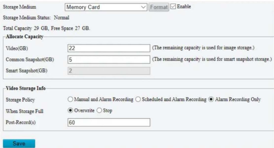
5.8.1 Memory Card

NOTE!
Before you use this function, make sure a memory card has been mounted on the camera.
Set Storage Media to Memory Card, and select Enable.
1. Storage Management
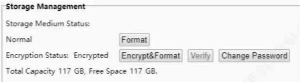

Caution!
To format a storage medium such as a memory card, stop using it first.
- Format: Format the storage medium without encryption.
- Encrypt&Format: Set an encryption password for the memory card, and then format it.
Example: When inserted an unencrypted memory card, to use the memory card encryption function, you must perform Encrypt&Format operation to encrypt the memory card. After encryption, insert the card into other device, if no encryption password is obtained or the password stored in the device is not consistent with the password of the memory card, then storage services such as recording storage, download, and search will not be available.
- Verify: Insert an encrypted memory card, if the password of the memory card is not consistent with the encryption password stored in the device, you can click Verify. When succeeded, you can normally use storage services, such as recording storage, download, and search.
- Change Password: You can change the encryption password if the memory card is encrypted.
• Storage Medium Status: Displays the health status of the memory card.

NOTE!
- This feature is only available to certain devices. Please refer to the actual interface.
- To monitor the memory card's health status, use a TF card that supports the health status monitoring function.
2. Allocate Capacity
Allocate storage space as needed.
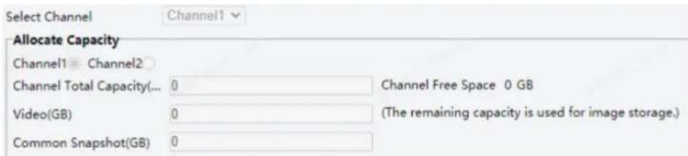
3. Storage Information.
Select a channel for storage information configuration first.
• To store manual recordings and alarm recordings
Choose Manual and Alarm Recording. By default, the main stream is stored.

| Item | Description |
| When Storage Full | Overwrite: When space is used up on the memory card, new data overwrites old data.Stop: When space is used up on the memory card, the camera stops saving new data. |
| Post-Record(s) | Sets the duration of alarm-triggered recording after the alarm ended. |
• To store scheduled recordings and alarm recordings
(1) Choose Scheduled and Alarm Recording.

(2) The default recording schedule is 24/7. To change the schedule, drag on the calendar or click Edit.

bar
| Day | Armed | Unarmed | |---|---|---| | Mon | 0 | 1 | | Tue | 1 | 2 | | Wed | 2 | 3 | | Thu | 3 | 4 | | Fri | 4 | 5 | | Sat | 5 | 6 | | Sun | 6 | 7 | | Mon (Edit) | 7 | 8 | | Tue (Edit) | 8 | 9 | | Wed (Edit) | 9 | 10 | | Thu (Edit) | 10 | 11 | | Fri (Edit) | 11 | 12 | | Sat (Edit) | 12 | 13 | | Sun (Edit) | 13 | 14 | | Mon (Edit) | 14 | 15 | | Tue (Edit) | 15 | 16 | | Wed (Edit) | 16 | 17 | | Thu (Edit) | 17 | 18 | | Fri (Edit) | 18 | 19 | | Sat (Edit) | 19 | 20 | | Sun (Edit) | 20 | 21 | | Mon (Edit) | 21 | 22 | | Tue (Edit) | 22 | 23 | | Wed (Edit) | 23 | 24 | | Thu (Edit) | 24 | 23 | | Fri (Edit) | 23 | 22 | | Sat (Edit) | 22 | 21 | | Sun (Edit) | 21 | 20 | | Mon (Edit) | 20 | 19 | | Tue (Edit) | 19 | 18 | | Wed (Edit) | 18 | 17 | | Thu (Edit) | 17 | 16 | | Fri (Edit) | 16 | 15 | | Sat (Edit) | 15 | 14 | | Sun (Edit) | 14 | 13 | | Mon (Edit) | 13 | 12 | | Tue (Edit) | 12 | 11 | | Wed (Edit) | 11 | 10 | | Thu (Edit) | 10 | 9 | | Fri (Edit) | 9 | 8 | | Sat (Edit) | 8 | 7 | | Sun (Edit) | 7 | 6 | | Mon (Edit) | 6 | 5 | | Tue (Edit) | 5 | 4 | | Wed (Edit) | 4 | 3 | | Thu (Edit) | 3 | 2 | | Fri (Edit) | 2 | 1 | | Sat (Edit) | 1 | 0 | | Sun (Edit) | 0 | -1 | | Mon (Edit) | -1 | -2 | | Tue (Edit) | -2 | -3 | | Wed (Edit) | -3 | -4 | | Thu (Edit) | -4 | -5 | | Fri (Edit) | -5 | -6 | | Sat (Edit) | -6 | -7 | | Sun (Edit) | -7 | -8 | | Mon (Edit) | -8 | -9 | | Tue (Edit) | -9 | -10 | | Wed (Edit) | -10 | -11 | | Thu (Edit) | -11 | -12 | | Fri (Edit) | -12 | -13 | | Sat (Edit) | -13 | -14 | | Sun (Edit) | -14 | -15 | | Mon (Edit) | -15 | -16 | | Tue (Edit) | -16 | -17 | | Wed (Edit) | -17 | -18 | | Thu (Edit) | -18 | -19 | | Fri (Edit) | -19 | -20 | | Sat (Edit) | -20 | -21 | | Sun (Edit) | -21 | -22 | | Mon (Edit) | -22 | -23 | | Tue (Edit) | -23 | -24 | | Wed (Edit) | -24 | -25 | | Thu (Edit) | -25 | -26 | | Fri (Edit) | -26 | -27 | | Sat (Edit) | -27 | -28 | | Sun (Edit) | -28 | -29 | | Mon (Edit) | -29 | -30 | | Tue (Edit) | -30 | -31 | | Wed (Edit) | -31 | -32 | | Thu (Edit) | -32 | -33 | | Fri (Edit) | -33 | -34 | | Sat (Edit) | -34 | -35 | | Sun (Edit) | -35 | -36 | | Mon (Edit) | -36 | -37 | | Tue (Edit) | -37 | -38 | | Wed (Edit) | -38 | -39 | | Thu (Edit) | -39 | -40 | | Fri (Edit) | -40 | -41 | | Sat (Edit) | -41 | -42 | | Sun (Edit) | -42 | -43 | | Mon (Edit) | -43 | -44 | | Tue (Edit) | -44 | -45 | | Wed (Edit) | -45 | -46 | | Thu (Edit) | -46 | -47 | | Fri (Edit) | -47 | -48 | | Sat (Edit) | -48 | -49 | | Sun (Edit) | -49 | -50 | | Mon (Edit) | -50 | -51 | | Tue (Edit) | -51 | -52 | | Wed (Edit) | -52 | -53 | | Thu (Edit) | -53 | -54 | | Fri (Edit) | -54 | -55 | | Sat (Edit) | -55 | -56 | | Sun (Edit) | -56 | -57 | | Mon (Edit) | -57 | -58 | | Tue (Edit) | -58 | -59 | | Wed (Edit) | -59 | -60 | | Thu (Edit) | -60 | -61 | | Fri (Edit) | -61 | -62 | | Sat (Edit) | -62 | -63 | | Sun (Edit) | -63 | -64 | | Mon (Edit) > Sun < Offs Mon (Edit)• To store alarm recordings only
Choose Alarm Recording Only.

5.8.2 Network Disk
Use a Network Attached Storage (NAS) server to store camera videos and snapshots.
- Set Storage Medium to NAS.
- Enter the server address.
- Enter the path to the destination folder on the NAS server. You can find the path by viewing the folder properties.
NOTE!
For dual-channel cameras, the server address and folder path are the same for the two channels. By default, the folder space is evenly shared by the two channels, among which, 85% space is used to store videos, and 15% is used to store common snapshots. You may change the Channel Total Capacity, video space, and common snapshot space as needed.


NOTE!
The path name may include the following: letters, digits, dots, spaces, and symbols / : , - _ @ = Other characters are not allowed and will cause failed NAS test.
4. After the test succeeded, click Save.

5.8.3 FTP
Upload images and videos to an FTP server for storage.
- Go to Setup > Storage > FTP.

2. Configure server parameters.
| Item | Description |
| Server IP | IP address of the FTP server. |
| Port No. | The default is 21. You can set a different port as needed. |
| Username | Username used to log in to the FTP server. |
| Password | Password used to log in to the FTP server. |
| Test | Test the connection to the FTP server. |
| Upload Images | Select the checkbox if you want to upload common (non-smart) snapshots. To configure an FTP server for smart snapshots, go to Setup > System > Server > Intelligent Server.Overwrite Storage: When the number of images in the folder of the lowest level reaches the threshold, the server continues to save new images by overwriting the existing images. For example, if the folder path is \IP\date, the level-2 folder “date” is the lowest. When the images uploaded on Jan. 4, 2022 exceeds 1,000, existing images in the 20220104 folder will be overwritten by new images.NOTE!If you select Overwrite Storage, make sure the last naming element of filename is Photo No..The default overwrite storage threshold is 1000 images, and the maximum is 100,000 images. |
| Upload Video | Select if you want to upload alarm-triggered recordings. |
| Convert Path into UTF8 Format | Select if you want to convert the path into UTF8 format. |
| Post-Record(s) | Fill in the number of seconds, which is the duration of the alarm-triggered recording after the alarm has ended. |
3. Configure the storage path.
| Item | Description |
| Photo | File path, up to 6 levels. If not specified, the default path “\IP\Data\Common” will be used. Common means common snapshots. |
| Filename, up to 20 fields are allowed. If not specified, the sequence number such as 1, 2, 3, ... will be used as the filename. | |
| Recording | File path, up to 6 levels. If no path is specified, the default path “\IP\Data.Common” will be used. |
| The default filename is “S+recording start time+E+recording end time”. For example, S20220104174903E20220104175002. |
4. Click Save.
5.9 Security
The security functions available may vary with camera model and version.
5.9.1 User
Go to Setup > Security > User to add, edit, or delete users.

- Add user
1. Click Add.
Common User
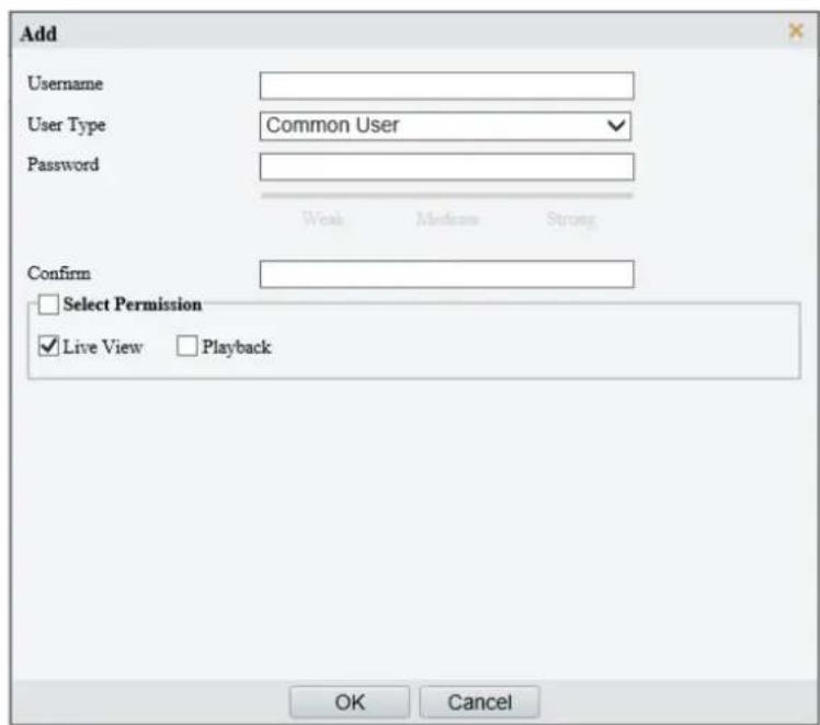
Operator
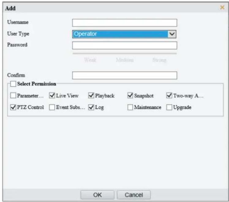
2. Configure the parameters.
| Item | Description |
| Username | Set the username that you prefer. |
| User Type | Choose Common User or Operator.NOTE!Up to 32 users are allowed, including admin (at least one), common users and operators (up to 31).Admin has all permissions in the system, including device operation and user management.Operator has higher privilege than common user and can configure in the web interface. |
| Password | Enter a password.NOTE!A strong password is required for new user. A strong password shall include 9-32 characters consisting of letters, digits, and special characters. |
| Confirm Password | Enter the password again. |
| Select Permission | Different user types have different permissions. Select permissions you want to assign to the new user.NOTE!You can select the Select Permission checkbox to select/deselect all permissions. |
3. Click OK.
- Edit user information
- Click the user.
- Click Edit.
Common User
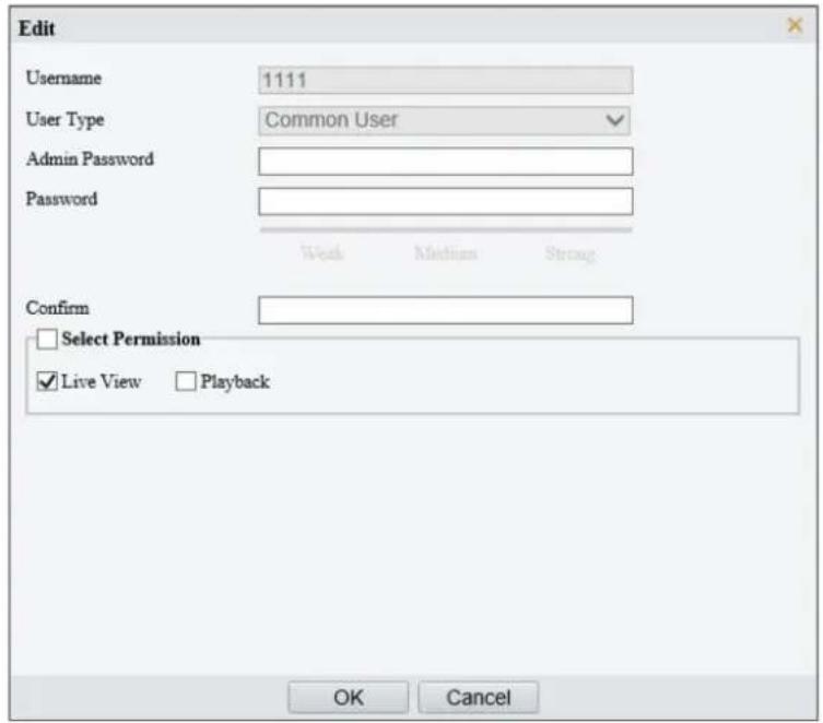
Admin
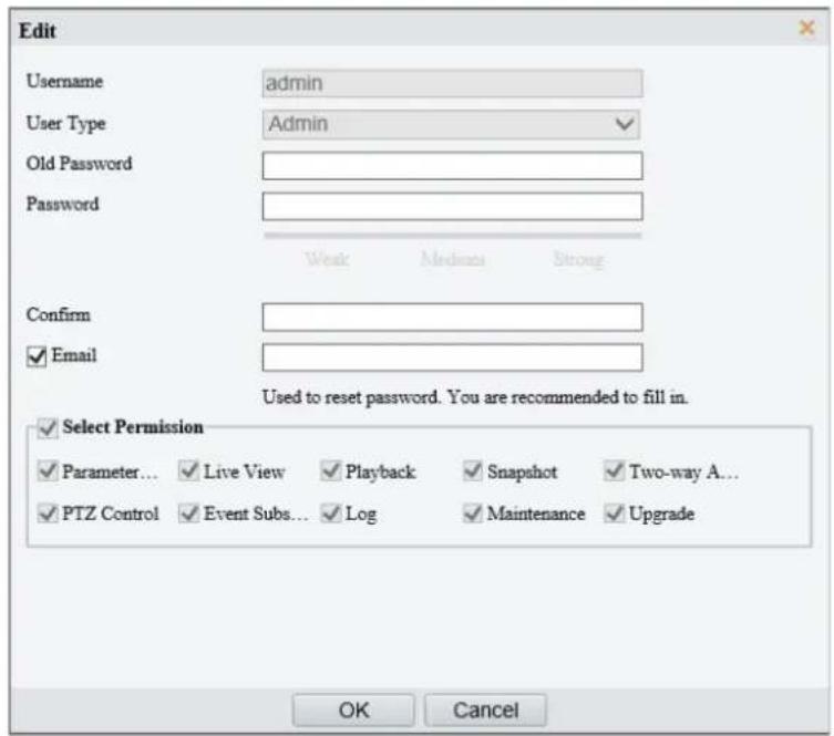
3. Configure the parameters.
| Item | Description |
| Admin Password | Password of administrator, not the user being editing. |
| Password | Enter a password that you prefer. |
| Confirm Password | Enter the password again. |
| Select Permission | Different user types have different permissions. Select permissions you want to assign to the new user.NoteYou can select the Select Permission checkbox to select/deselect all permissions. |
4. Click OK.

NOTE!
- Only admin can change the device password. The new password must be different from the old.
- Only admin can change the username and password of a new user. If the user is logged in, the user will log out automatically and must use the new username and password to log in.
- Delete a user
Click the user, click Delete, and then click OK to confirm.
5.9.2 HTTPS
Enable HTTPS to securely transmit video data of the camera.
- Go to Setup > Security > Network Security > HTTPS.

- Click On to enable HTTPS.
- (Optional) Click On to enable Auto Redirect to HTTPS. When enabled, you will be automatically redirected to the login page via the HTTPS protocol. After re-login, a secure information transmission channel is established.

NOTE!
- When disabled, you can use either HTTP or HTTPS protocol to log in.
-
The default HTTPS port is 443. To use a different port, go to Setup > Network > Port.
-
Click to choose a server certificate.
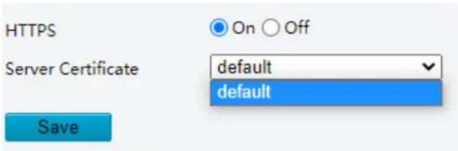
-
Use the default certificate
• A created certificate. See Certificate Management. -
Click Save.
5.9.3 Authentication
Configure RTSP authentication and HTTP authentication to improve the security of network transmission. Only after successful authentication can data such as videos, audios, text, and images be transferred on the network.
- Go to Setup > Security > Network Security > Authentication.
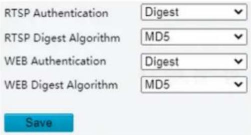
2. Choose an authentication mode.
| Item | Description |
| RTSP Authentication | Choose an authentication mode from the drop-down list. The default is Digest.Basic: Basic authentication. The username and password are encrypted by base 64, which imposes serious security risks.Digest: Digest authentication. Displays RTSP digest algorithm configuration. The default is MD5.➢ Digest MD5: Digest authentication, which uses MD5 to protect the username, password, and domain of the requester, not transferred on network in plaintext and provides higher security.➢ Digest SHA256: Digest authentication, which uses SHA256 for authentication and provides higher security than Digest MD5.➢ Digest MD5/ SHA256: Supports MD5 or SHA256 algorithm adaption.None: Transmit message without authenticating the RTSP address. |
| Web Authentication | Choose an authentication mode from the drop-down list. The default is Digest.Digest: Digest authentication. Displays Web digest algorithm configuration. The default is MD5.➢ Digest MD5: Digest authentication, which uses MD5 to protect the username, password, and domain of the requester, not transferred on network in plaintext and provides higher security.➢ Digest SHA256: Digest authentication, which uses SHA256 for authentication and provides higher security than Digest MD5.➢ Digest MD5/ SHA256: Supports MD5 or SHA256 algorithm adaption.None: Transmit message withoutenticating the Web address. |
3. Click Save.
5.9.4 Registration Information
You can set to hide vendor information of the camera from the server.
- Go to Setup > Security > Registration Information.
- Enable Hide Vendor Info. Vendor information will not be displayed on the management platform.
Hide Vendor Info
Save
3. Click Save.
5.9.5 ARP Protection
Configure ARP protection by binding the gateway's IP address with its MAC address to prevent ARP spoofing attacks.
- Go to Setup > Security > Network Security > ARP Protection.
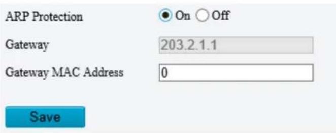
- Enable ARP Protection.
- Enter the gateway's MAC address.
- Click Save.
5.9.6 IP Address Filtering
Use IP address filtering to allow or forbid access from specified IP addresses.
- Go to Setup > Security > Network Security > IP Address Filtering.
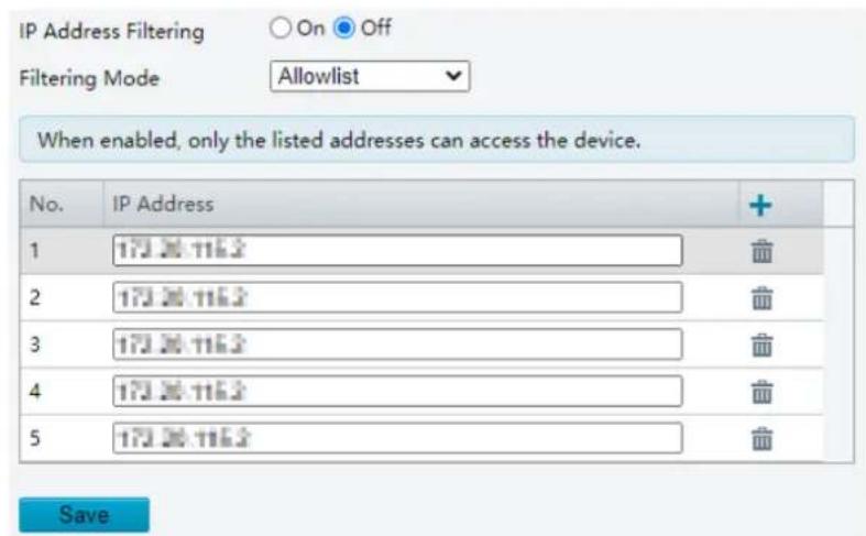
- Click On to enable IP Address Filtering.
- Choose Allowlist or Blocklist.
Allowlist: Only allows access from the added IP addresses.
Blocklist: Denies access from the added IP address.
- Click , enter IP addresses.
Up to 32 IP addresses can be added. Duplicate addresses are not allowed.
The first byte of the IP must be 1-233, and the fourth byte cannot be 0. Invalid IP addresses such as 0.0.0.0, 127.0.0.1, 255.255.255.255, and 224.0.0.1 are not allowed.
- Click Save.
5.9.7 MAC Address Filtering
Use MAC address filtering to allow or deny access to the device from specified MAC addresses.
- Go to Setup > Security > Network Security > MAC Address Filtering.

- Click On to enable MAC Address Filtering.
- Choose Allowlist or Blocklist.
Allowlist: Only allows access from the added MAC addresses.
Blocklist: Denies access from the added MAC address.
-
Click to add a new MAC address. Up to 32 addresses are allowed.
-
Click Save.
5.9.8 Access Policy
Access policies are used to prevent unauthorized access and operation from the network.
- Go to Setup > Security > Network Security > Access Policy.
- Illegal Access Lock


NOTE!
If illegal access lock is disabled, the camera will not lock the account no matter how many times an incorrect password is input.
| Item | Description |
| Illegal Access Lock | If the client IP address is not on the blocklist, the input username is correct, but the input password is wrong, it is an illegal access attempt.NOTE!When an account is locked, information including the username, IP address, etc, is logged by the system.The user can unlock the account by disconnecting power and rebooting the camera. |
| Access Login Limit | The maximum number of illegal access attempts allowed. The account is locked when the limit is reached. |
| Lock Time (min) | Integer within the range of 1-120. |
Example: User A tries to log in from the client IP address 192.168.1.33 and is locked. Then user A cannot log in within the lock time, but user B is not affected and can still log in from the same IP address.
- Session timeout
A session is the connection established between the client (Web browser) and the server (camera). When session timeout is enabled, if the client cannot obtain or save configurations within the set time, the user will automatically log out and go to the login page.

NOTE!
Only admin can enable or disable this feature.
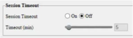
| Item | Description |
| Session Timeout | Sessions are counted as follows. Take one device as an example.If the session is established using one web browser from one client IP, there is one session.If sessions are established using one web browser from one client IP, there are two sessions.If sessions are established using two web browsers from two client IPs (two browsers from each IP), there are four sessions.NOTE!Up to 36 sessions are allowed at the same time. |
| Timeout (min) | Enter an integer within the range of 1-120.NOTE!The timer restarts when the session is re-established after a reboot. |
- WEB Service
When disabled, you will not be able to log in to the device's Web interface for device management. You can restore the WEB service to its default status (On) using EZTools.
WEB Service
2. Click Save.
- Friendly password
Users are not affected when friendly password is enabled. When friendly password is disabled, users who are already logged in with a weak password will be forced to set a strong password before the user can proceed with other actions in the web interface.

NOTE!
Friendly password is not available to all cameras.
5.9.9 Certificate Management
On the Certificate Management page, you can create and manage certificates, view certificate properties, etc.
1. Go to Setup > Security > Network Security > Certificate Management.

1. Certificate
- Create a self-signed certificate or import a certificate.
- Create a self-signed certificate for application scenarios with low-security requirements.

(1) Click Create Self-Signed Certificate.
(2) Complete the settings.
| Item | Description |
| Certificate Name | Set a name as needed. |
| Public Key | Choose a length for the public key: 2048 or 1024. Default: 2048. |
| Country | Enter the two-character country code, for example, CN for China. |
| Domain Name/IP | Enter the device's IP address or domain name. |
| Valid Period(day) | Enter the validity period of the certificate. |
| Province | Enter the complete province name. |
| City | Enter the complete city name. |
| Organization | Enter the organization name. |
| Organizational Unit | Enter the organizational unit name. |
| Enter a valid email address of the contact. |
(3) Click OK.
- Import a non-CA certificate.
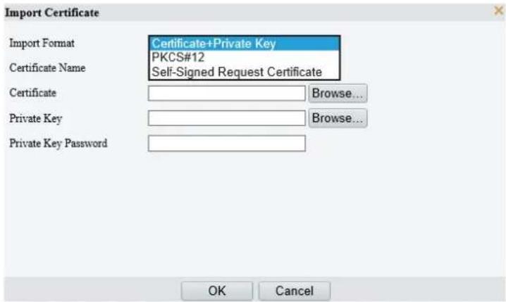
(1) Click Import Certificate.
(2) Complete the settings.
| Item | Description |
| Import Format | You may choose Certificate+Private Key, PKCS#12, or Self-Signed Request Certificate. |
| Certificate Name | Enter the certificate name. |
| Certificate | Click Browse and locate the certificate. |
| Private Key | Click Browse and locate the private key. |
| Private Key Password | Enter the private key password. |
(3) Click OK.
- (Optional) Create a certificate request to obtain a trusted signed certificate for application scenarios with high-security requirements.

(1) After creating or importing a certificate, select the certificate, click Create Certificate Request.
(2) Complete the settings.
(3) Click OK.
NOTE!
After the certificate request is created, export the certificate request file. After the certificate authority (CA) signs and issues a certificate in accordance with the request, import the certificate into the device.
- Export certificate.

Click Export Certificate to save the certificate to your computer.
- Delete certificate.
Select a certificate and delete it. A certificate that is in use cannot be deleted.
• View certificate properties.
Select a certificate to view its properties.
| Certificate Name | default | |
| Issued By | Domain Name/IP | 192.168.0.1 |
| Country | CN | |
| Province | ZJ | |
| City | HZ | |
| Organization | EmbeddedSoftware | |
| Organizational Unit | Uniview | |
| Issued To | Domain Name/IP | 192.168.0.1 |
| Country | CN | |
| Province | ZJ | |
| City | HZ | |
| Organization | EmbeddedSoftware | |
| Organizational Unit | Uniview | |
2. CA Certificate
A CA certificate is a certificate issued by a trusted certificate authority (CA) and thus is more secure and reliable.
- Click Import Certificate.
- Enter the certificate name, select the certificate.

- Click OK.
- Delete certificate.
Select a certificate and delete it. A certificate that is in use cannot be deleted.
• View certificate properties.
Select the certificate to view its properties.
5.9.10 Watermark
Use watermark to encrypt custom information in videos to prevent tampering.

NOTE!
• Watermarks can be verified using EZPlayer (available for download from Uniview website).
- For devices with two video channels, watermark parameters need to be configured for the channels separately.
1. Go to Setup > Security > Watermark.

- Enable Watermark.
- Set watermark contents, which may include uppercase letters, lowercase letters, and digits. Up to 16 characters are allowed.
- Click Save.
5.10 System

NOTE!
User operations in this module may vary with camera model.
5.10.1 Time
Set the device's system time manually or sync it with a server.
1. Go to Setup > System > Time.
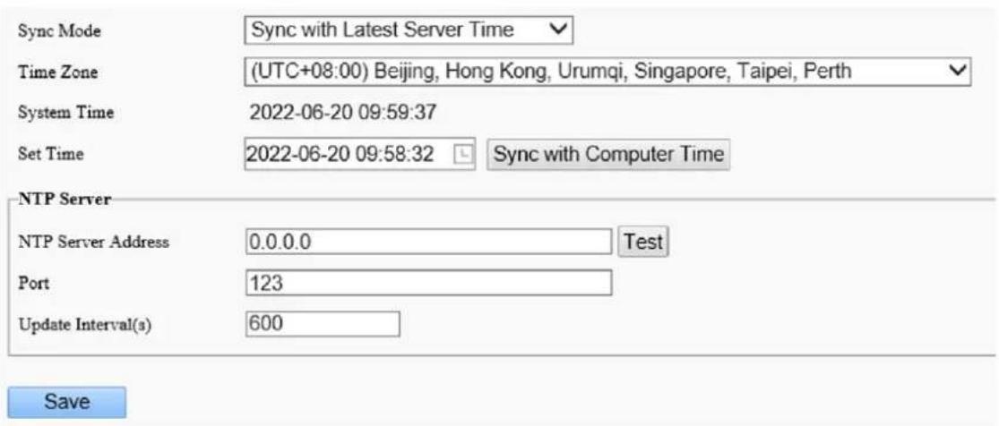
- Set the system time.
- Set manually in the Set Time field.

NOTE!
When setting the system time manually, you need to set Sync Mode to Sync with System Configuration; otherwise, the camera will still sync with other time sources after you set it manually.
- Sync time
| Item | Description |
| Sync with System Configuration | Default. Time provided by the system's built-in time module. |
| Sync with Latest Server Time | The camera regularly syncs time with all the connected servers. |
| Sync with Management Server(Non-ONVIF) | The camera regularly syncs time with the server that is not connected via Onvif. |
| Sync with Management Server(ONVIF) | The camera regularly syncs time with the server that is connected via Onvif. |
| Sync with NTP Server | The camera syncs time with the NTP server.You need to configure the server address, port, and update interval (range: 30s-86400s). You can click Test to test it. |
| Sync with Cloud Server | The camera syncs time with the cloud server once when it gets online. The camera does not sync again until it gets offline and online again. |
| BeiDou Module Auto Sync | The camera syncs time with BeiDou satellites through the BeiDou module (if equipped). |
| Sync with Computer Time | The camera syncs time with the client computer from which you log in to the camera. |
3. Click Save.
5.10.2 DST
- Go to Setup > System > Time > DST.

-
Enable DST, and set the start time, end time, and DST bias.
-
Click Save.
5.10.3 Device Information
1. Device Information
Set device information including device name, device id, mounting height, etc., which can be used in smart FTP, OSD, etc.
- Go to Setup > System > Product Info > Product Info.
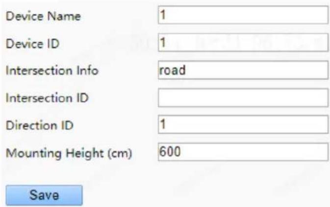
- Complete the information as needed.
- Click Save.
2. Geographic Position
Collects data such as the device's latitude and longitude, speed, and movement direction via the positioning function. The collected data can be displayed on the live view image using OSD and can also be reported to the data center by configuring a smart server.

NOTE!
This function is available to certain device models. Please refer to the actual interface.
1. Go to Setup > System > Device Info > Geographic Position.

2. Select a Latitude & Longitude Mode and set other parameters as needed.
| Item | Description |
| Automatic | The latitude and longitude information is grayed out and cannot be set manually. And the device will collect the information from the positioning module.Note:This function is available to certain device models. Please refer to the actual interface. |
| Manual | You can manually set the latitude and longitude information. |
- (Optional) By default, Report Data to Center is enabled by default. If reporting is not required, you can unselect this option. This function requires UDP platform configuration, which can be configured in Setup > Network > Platform Access > IoT Platform > UDP Platform.
- Click Save.
5.10.4 Ports & External Devices
The RS485 port is used for data transmission between the camera and external third-party devices for PTZ control, OSD, audio collection, illumination control, etc. The serial port parameters configured on the camera must match that of the connected external device.
- Go to Setup > System > Ports & Devices > Serial Port.
- Set Port Mode and configure the parameters.
| Item | Description |
| Baud Rate | Data transmission speed (unit: bits per second). The greater the value, the faster the transmission speed, and the shorter the transmission distance. Usually the default value is applicable. |
| Data Bit | The actual number of data bits in a group of data packets. Usually the default value is applicable. |
| Stop Bit | Indicates the end of transmission of a group of data. Usually the default value is applicable. |
| Parity Bit | Used to check whether the received data bits are erroneous. You can choose Odd-Parity Check or Even-Parity Check. |
| Flow Control | Used to control data transmission to prevent data loss. |
- PTZ control
To control the PTZ using a third-party device, set Port Mode to PTZ Control.
By sending PELCO-D instructions through the RS485, you can control PTZ without using the PTZ control panel.
(1) Set Port Mode to Local PTZ Control.
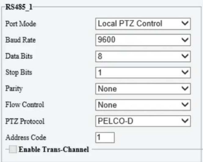
Save
(2) Configure the parameters.
| Item | Description |
| PTZ Protocol | Choose the correct PTZ protocol: PELCO-D, PELCO-P, INTERNAL-PTZ, ALEC, VISCA, ALEC_PELCO-D, ALEC_PELCO-P, MINKING_PELCO-D, MINKING_PELCO-P, YAAN, Private-KR.Some camera models support preset IDs from 1 to 1024 when the PTZ protocol is PELCO-D, and preset IDs from 1 to 255 when the PTZ protocol is other protocols. |
| Address Code | Set the PTZ address code.NOTE!This parameter is configurable only when Port Mode is set to PTZ Control and PTZ Protocol is set to Local PTZ Control. |
- Trans-channel
Used to transmit data between the RS485 port and the third-party device.

NOTE!
This feature is available only on certain camera models.
(3) Set Port Mode to Trans-Channel.

Save
(4) Enable Trans-Channel.
(5) Enter the destination address and port, that is, the IP address and port number of the third-party device to which the transparent channel is connected.
(6) Click Save.
- OSD
Receive serial port information from the third-party device through the RS485 port and then overlay the parsed information on the OSD.

NOTE!
In order for the camera to correctly parse the received serial port information, make sure the serial port information sent from the third-party device conforms to our data formats. Contact our technical support for more information.
(1) Set Port Mode to OSD.

Save
(2) Select Enable OSD Report, so OSD data will be uploaded to the platform.
(3) Click Save.
• Trans-Channel via ONVIF
Use the RS485 port for data transmission between the camera and third-party devices via Onvif.
(1) Set Port Mode to Trans-Channel via ONVIF.
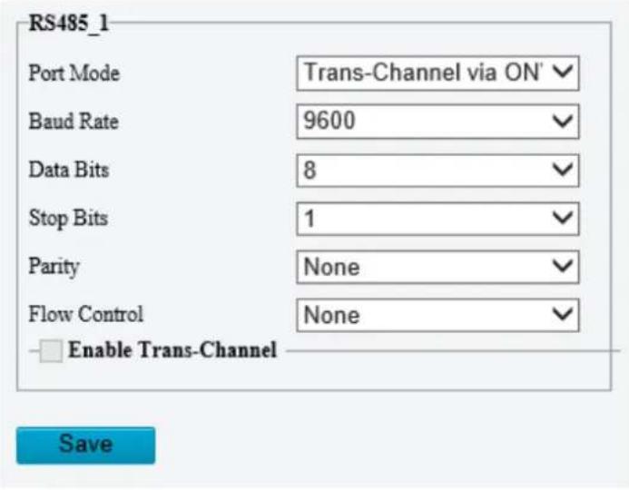
(2) Configure the parameters.
(3) Click Save.
- Illumination
Use the RS485 port to transmit data between the camera and the third-party illuminator.
(1) Set Port Mode to Illumination.

(2) Configure the parameters.
(3) Click Save.
NOTE!
The current module serial port protocols are UART and RS232. The PTZ control modes include Internal Control and External Control.
- Internal Control: The module controls the lens and the PTZ rotates.
• External Control: The PTZ rotates and controls the module lens.

- Wiper Control
Configure wiper parameters to control the wiper.
(1) Go to System > Ports & Devices > External Device.
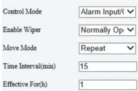
(2) Configure wiper parameters.
| Item | Item | Description |
| Control Mode | Serial Port | The wiper is controlled through PELCO-D instructions, so the PTZ protocol must be set to PELCO-D. See PTZ Protocol for more information. |
| Alarm Input/Output | Use alarm input and output to open or close the circuit and control the wiper. | |
| Enable Wiper | Normally Open/Normally Closed | Set according to the actual working status of the wiper. |
| Move Mode | One Time/Repeat/Automatic | One Time: The wiper works once every time you click the wiper icon on the PTZ control panel. |
| Repeat: You need to set the Effective For and Time Interval parameters. The Effective For parameter sets the duration of the Repeat mode (1 to 24 hours), and the Time Interval parameter sets the interval between two wiper movements (1 to 60 minutes).NOTE!If Time Interval is set to 60 minutes and Effective For is set to 1 hour, then the wiper works once at the last minute and then stops.Only integers are allowed. | ||
| Automatic: Use a rain sensor to detect rains and automatically activate the wiper when the threshold is reached. |
(3) Click Save.
5.10.5 Maintenance
1. Maintenance
System maintenance include software upgrade, system configuration, diagnosis information, power output, and heater settings.
Go to Setup > System > Maintenance.
- Software upgrade

NOTE!
- Make sure the version to be used matches the device; otherwise, exceptions may occur.
- The version file is a .zip file that includes all the upgrade files.
- Power must be connected throughout the upgrade.
Local upgrade
(1) Click Browse, locate the version. (If applicable) select Upgrade Boot Program to upgrade the boot program.
(2) Click Upgrade to start. The device will restart automatically after the upgrade is completed.
Component upgrade
Check for upgradable component such as pan/tilt unit, illuminator, etc., and available versions.
Cloud upgrade
Click Detect to check for new versions. You can perform a cloud upgrade if a new version is available on the cloud server.
- System configuration
You can export the current configurations of the camera to the client computer or an external storage device for backup, so when necessary, you can restore camera configurations by importing the backup file.

CAUTION!
- Restoring defaults will restore all settings to factory defaults except the administrator password, network interface settings, and system time.
- Before you import a configuration file, make sure the file matches the camera model; otherwise, unexpected results may occur.
- The camera will restart after importing the configuration file.
Import configurations

(1) Click Browse beside the Import button.
(2) Locate the configuration file, click Import. A dialog box appears.
(3) Enter the password and confirm.
(4) Click OK.
Export configurations
(1) Click Browse beside the Export button.
(2) Choose the destination folder, click Export. The File Encryption dialog box appears.
(3) Enter the password and confirm.

NOTE!
Some devices support modifying the name of the exported configuration file. After modifying its name, you can also import the modified configuration file to the device again.
Restore defaults
Click Default. The system will restore default settings except network settings and user settings. To restore all settings, select Restore all settings to defaults without keeping current network and user settings.
• Diagnosis information
Diagnosis information includes logs and system configurations and can be exported to your client computer.

(1) Click Browse and choose the destination.
(2) Click Export.

NOTE!
Diagnosis information is exported as a compressed file. You need to decompress it first (using decompression tools like WinRAR) and then open the file using a text editor (like Notepad).
- Power output
The camera can supply power to external devices with lower power consumption such as a sound pickup.
Power Output
12 VDC
- Restart device

CAUTION!
Restarting the camera will interrupt the ongoing service.
Restart
Restart device
Click Restart and then confirm to restart the device. You may set a schedule to reboot the camera automatically at the set time.
- Heater
Use the heater to eliminate water droplets on the lens in a high humidity environment.

(1) Enable Heater.
(2) Set Remaining Heating Time.
2. Network Diagnosis
Go to Setup > System > Maintenance > Network Diagnosis.

- Select NIC
NIC1 is the camera's IP address.
- IP/port filter
All: Capture all packets of the camera.
Specify: Capture packets of the specified port or IP.
Filter: Filter packets of the specified port or IP and capture other packets.
- Custom Rules
Select Custom Rules and set the rules.
Click Start Capture to start capturing packets. After packet capture is finished, save data and view the diagnosis.
• Test network delay and packet loss rate
Test network connectivity by sending test packets to a test address.

Test Address: Must be a valid IP address or domain name.
Packet Size (Bytes): Size of test packets to be sent. Range: [64-65507]. Sometimes a high delay may be caused by a large packet size. If the test failed, set a smaller packet size and then try again.
Test results include average delay and packet loss rate.
– Average delay: Average length of time from test packets are sent till responses are received.
- Packet loss rate: Ratio of lost packets to the sent packets.
5.10.6 Logs
Search camera operation logs and download to your computer.
Go to Setup > System > Log.
![Time 2022-06-09 00:00:00 2022-06-09 23:59:59 Main Type AlarmEvent Sub Type All Operation: Query Export No. Type Sub Type Data Time Username IP Result 1 Operator Login 2022-06-09 10:25:05 adults '✓✓✓✓ Succeeded 2 Operator Upgrade 2022-06-09 10:18:25 adults |||||| Succeeded 3 Operator Login 2022-06-09 10:05:29 adults E##LLLL Succeeded Total 3 < < [1] /1 >>](/content/2026/06/1364534/images/fc09422d6626e0f2b9189409fca504e0d98cb0cc95f4df37a201711dd6e08fdf.jpg)
- Set a time range and choose main and sub log types.
- Main type: Including system operation, alarm parameter configuration, network configuration, audio and video configuration, PTZ configuration, image configuration, smart configuration, system configuration, storage configuration, and alarm events.
- Sub type: You can choose up to 5 types or choose All.
- Click Search. Up to 100 logs can be displayed. The latest logs are displayed on the top.
- Click Export to save search results as a .csv file to the client computer.
5.10.7 System
For certain dual-channel cameras, you can switch between 1-channel and 2-channel output mode on the Live View page.
- Go to Setup > System > System.
Video Output Mode
○ 1-Channel ● 2-Channel
Note: The iris settings do not take effect when the zoom is less than 1x.
Save
-
Choose a video output mode.
-
2-Channel: Default mode. In this mode, two channels of live video are displayed, with channel 1 (upper) showing the fixed focal image, and channel 2 (lower) showing the varifocal image.
- 1-Channel: In this mode, two channels of live video are merged into one panoramic image by splicing images with adjusted zoom ratios.

CAUTION!
If you need to adjust iris in 1-channel mode, make sure the zoom ratio is greater than or equal to 1X; otherwise, the iris adjustment does not take effect.
- Click Save. A message appears, prompting you to switch the output mode and restart the camera.
- Click OK. The new settings take effect after the camera restarts automatically.
5.11 Other Configurations
Fisheye

NOTE!
This function is available to fisheye cameras only.
Choose to decode live videos by hardware decoding or software decoding.
1. Hardware Decoding
Hardware decoding is to decode the obtained live videos by the camera itself. On the Hardware tab, you can set the mount method and display mode, and configure the stream type for each channel.
Table 5-1 Mount Method
| Icon | Description | |
 | Ceiling Mount | |
 | Wall Mount | |
 | Desktop Placement | |
Table 5-2 Display Mode
| Icon | Description |
 | Fisheye. Displays the original image, fisheye stream, the raw image captured by the sensor. This mode uses a wide-angle view, close to the convex eye view of a fish, to produce a large curved image while distorting the perspective and angle of objects in the image. |
 | Fisheye+4PTZ. For PTZ streams, you can use the direction button on the screen to adjust the PTZ direction. |
 | Panoramic. Displays the panoramic view, converting the original image to a rectangular image by certain calibration methods.When the mount method isCeiling Mount() and the display mode isPanoramic, you can choose to split the image horizontally or vertically. Additionally, you can set the dewarping angle. Range: 0-90°.0° : Closest to the center of the fisheye, with the least distortion.90° : Furthest from the center of the fisheye, with the largest distortion.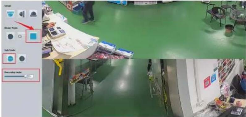 |
2. Software Decoding
Software decoding is to decode live videos using the PC where the browser is located. Its performance is depending on the decoding capability of the PC.
Click on the live view image to open/close the software decoding panel.
- When the mount method is Ceiling Mount, you can choose the following display methods: Original Image, 360°Panoramic+1PTZ, 180°Panoramic, Fisheye+3/4/8PTZ, and 360°Panoramic+6PTZ.
- When the mount method is Wall Mount, you can choose the following display methods: Original Image, Panoramic, and Panoramic+3/4/8PTZ.

NOTE!
When using the hardware decoding, you can switch to software decoding only when the display method is the original image.
Table 5-3 Display Method
| Icon | Description | |
 | Original image. | |
 | 360° pamoramic+1PTZ. Each block can be dragged to view and interact with each other.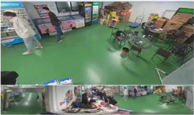 | |
| Icon | Description | ||
 | 180° panoramic view. Split the fisheye view into two windows. You can drag to view the image horizontally. | ||
 |  |  | Fisheye+3/4/8PTZ. Every block can be dragged to view, making it easy to locate locally and globally. |
 | 360° panoramic view+6PTZ.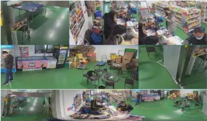 | ||
 |  |  | Panoramic view+3/4/8PTZ. |

CAUTION!
When the mount method of fisheye camera is Ceiling Mount or Desktop Placement, the panoramic image (double 180° image) is the dewarping image of the fisheye image (360° image). Please select the appropriate mounting angle according to the actual monitoring view requirements.
Example: If the device is mounted on the ceiling of a hall, and the angle between the tail cable hole (LOGO) on the bottom of the device and the target is approximately 135^ clockwise, the dected target can be displayed on the center top of the panoramic view.



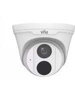

- Network Camera User Manual
- Disclaimer
- Safety Instructions
- CAUTION!
- Environmental Protection
- Safety Symbols
- Contents
- Disclaimer ...... i
- Safety Instructions ...... i
- Environmental Protection....i
- Safety Symbols ...... i
- Login 1
- Live View 3
- PTZ Control 8
- General Parameters 20
- Playback....21
- Photo 24
- Setup 25
- Video & Audio 47
- PTZ 55
- Image 59
- Smart....78
- Alarm 129
- Storage 143
- Security 148
- System 159
- Other Configurations.... 170
- Login
- Preparation
- Check before login
- NOTE!
- Login
- Privacy Policy of Uniview Technologies
- Introduction
- Scope of Information Collection
- Global Search
- Live View
- Live View
- Live view page of dual-channel camera
- Live view page of single-channel camera
- Pixel Calculation
- Digital Zoom
- Capture
- 5ePTZ
- PTZ Control
- 3D Positioning
- Area Focus
- Preset
- Patrol
- Add a patrol route
- Configure basic patrol route
- Click
- Complete the action settings.
- Click OK.
- Click +
- - Record a patrol route
- Configure composite route
- Call a patrol route
- Call basic patrol route manually
- Call by schedule
- General Parameters
- Playback
- Playback Toolbar
- Search and Playback
- Recording Download
- Photo
- Setup
- Local Parameters
- Smart
- Video
- Recording and Snapshot
- Set local parameters as needed.
- Click Save.
- Network
- Basic Config
- Ethernet
- Mobile Network
- DNS
- DDNS
- Port
- Go to Setup > Network > Basic Config > Port.
- Port Mapping
- Save
- Click Save.
- 802.1x
- Service Configuration
- Go to Setup > Network > Service Config > E-mail.
- SNMP
- Set SNMP parameters.
- - SNMPv3
- - SNMPv2
- QoS
- RTSP
- ONVIF (ANR)
- Platform Access
- Intelligent Platform
- - UNV
- Set server parameters.
- Configure the image storage path.
- Click Save.
- EZCloud
- Option 1: Add cameras on the UNV-Link app
- Option 2: Add cameras on the EZCloud website
- Log in to the website.
- Go to Device Management > My Cloud Devices and click Add.
- Click OK.
- Click Save.
- IoT Platform
- Go to Setup > Network > Platform Access > IoT Platform.
- WebSocket
- Go to Setup > Network > Platform Access > WebSocket.
- Set the parameters.
- Alarm Platform
- Go to Setup > Network > Platform Access > Alarm Platform.
- Select Enable.
- Video & Audio
- Video
- Video
- Go to Setup > Video & Audio > Video.
- Select a capture mode for your camera.
- Set stream parameters.
- Adaptive Streams
- Snapshot
- Audio
- Audio
- Set audio output parameters.
- Audio File
- Set audio file parameters.
- ROI
- Set ROI areas.
- View Cropping
- Media Stream
- Media Stream
- Click OK.
- RTSP Multicast
- PTZ
- Basic PTZ Settings
- Preset Image Freeze
- Stop PTZ Control After Timeout
- PTZ Speed
- PTZ Rectification
- Power Off Memory
- Auto Guard
- Go to Setup > PTZ > Auto Guard.
- Enable Auto Guard and complete the settings.
- Pan/Tilt Limit
- Go to Setup > PTZ > Limit.
- Set the pan and tilt limits. Take the tilt limit configuration as an example:
- Preset Snapshot and Patrol Resumption
- Orientation
- North Calibration
- Zero Position
- Image
- Image
- Scenes
- Click Scenes.
- Scenes
- Set the parameters.
- Image Enhancement
- On the Image page, click Image Enhancement.
- Set the image enhancement parameters.
- Exposure
- On the Image page, click Exposure.
- Set the exposure parameters.
- Smart Illumination
- Focus
- White Balance
- Defog
- Heatwave Reduction
- Lens Info
- On the Image page, click Lens Info.
- Set the lens parameters.
- Dewarping
- On the Image page, click Advanced.
- Enable Dewarping and set the dewarping level as needed.
- Image Stabilization
- Select On or Off to enable or disable image stabilization, and configure the parameters.
- Non-Uniformity Correction
- On the Image page, select Channel 2 and click Advanced.
- Select the non-uniformity correction mode.
- Reduce Vertical Stripe Noise
- Drag the slider or enter a number to set the intensity. The greater the value, the blurrier the image.
- Thermal Imaging Palette
- Image Scene Switch
- Engineering Parameters
- Video Standard
- OSD
- Overlay OSD Contents.
- Privacy Mask
- Quick Focus
- Smart
- Alarm-triggered Actions
- Alarm output
- Alarm-triggered storage
- Alarm-triggered PTZ
- Arming Schedule
- Smart Service Switch
- - Preset Switch
- Cross Line Detection
- Enter Area Detection
- Leave Area Detection
- Intrusion Detection
- Object Removed Detection
- Object Left Behind Detection
- Defocus Detection
- Scene Change Detection
- Face Detection
- Set the photo OSD.
- Click Save.
- Face Recognition
- The imported face data are shown as below:
- Add monitoring tasks.
- Human Body Detection
- Multi-Target Detection
- Mask undesired areas.
- Set photo OSD.
- Click Save.
- Traffic Monitoring /ANPR
- Traffic Monitoring
- ANPR
- Snapshot Handling
- Photo OSD
- Heat Map
- Go to Setup > Intelligent > Smart.
- Select Heat Map and click 🔒. A page as shown below appears.
- Set the detection rules.
- People Flow Counting
- Crowd Density Monitoring
- Auto Tracking
- Smoke and Fire Detection
- Metadata Collection
- Collect Metadata
- Advanced Settings
- Photo
- Detection
- Tracking
- Panoramic Linkage
- Calibration
- Choose a calibration mode.
- Configure Linkage
- Set track parameters.
- Alarm
- Thermal Imaging Alarm
- Fire Detection
- Set Shield Area.
- Temperature Detection
- Go to Setup > Alarm > Thermal Alarm > Temperature Detection.
- Select Enable Temperature Detection.
- Set temperature parameters.
- Set the detection rule. Up to 12 detection rules are allowed.
- Click
- Common Alarm
- Motion Detection
- Basic Mode
- Ultra Mode
- Tampering Detection
- Audio Detection
- Alarm Input
- Click Save.
- Event Linkage
- One-key Disarming
- Storage
- Memory Card
- Storage Management
- Allocate Capacity
- Storage Information.
- Network Disk
- After the test succeeded, click Save.
- FTP
- Configure server parameters.
- Configure the storage path.
- Security
- User
- - Add user
- Click Add.
- Common User
- Operator
- Configure the parameters.
- Click OK.
- Admin
- Configure the parameters.
- HTTPS
- Authentication
- Choose an authentication mode.
- Registration Information
- ARP Protection
- IP Address Filtering
- MAC Address Filtering
- Access Policy
- - Session timeout
- - WEB Service
- Click Save.
- - Friendly password
- Certificate Management
- Go to Setup > Security > Network Security > Certificate Management.
- Certificate
- CA Certificate
- Watermark
- Go to Setup > Security > Watermark.
- System
- Time
- Go to Setup > System > Time.
- DST
- Device Information
- Device Information
- Geographic Position
- Go to Setup > System > Device Info > Geographic Position.
- Select a Latitude & Longitude Mode and set other parameters as needed.
- Ports & External Devices
- Set Port Mode to Trans-Channel.
- Set Port Mode to OSD.
- Maintenance
- Maintenance
- Power Output
- Network Diagnosis
- Logs
- System
- Other Configurations
- Fisheye
- Hardware Decoding
- Software Decoding
Brand : UniView
Model : IPC3615SE-ADF28KM-WL-I0
Category : Surveillance Camera