
RS500 - Capteur de pluie sans fil Irritrol - Free user manual and instructions
Find the device manual for free RS500 Irritrol in PDF.


| Product Type | Irrigation Controller |
| Model | RS500 |
| Brand | Irritrol |
| Number of Zones | 4-6 zones (expandable) |
| Power Supply | 24 VAC, 50/60 Hz |
| Battery Backup | 9V battery (for scheduling) |
| Dimensions (H x W x D) | 7.5 x 5.5 x 2.5 in (19 x 14 x 6.4 cm) |
| Weight | 1.2 lbs (0.54 kg) |
| Main Functions | Programmable schedules, rain delay, manual override, seasonal adjustment |
| Programming | 3 independent programs, up to 4 start times per program |
| Display | LCD screen with backlight |
| Watering Duration | 1 minute to 99 minutes per zone |
| Rain Sensor Compatible | Yes (dry contact) |
| Protection Rating | IP54 (splash resistant) |
| Operating Temperature | 32°F to 140°F (0°C to 60°C) |
| Maintenance | Clean filter periodically; check valve solenoids |
| Safety | Low voltage (24 VAC) for indoor/outdoor use |
| Spare Parts Available | Transformer, solenoid, faceplate |
| Warranty | 2 years limited |
Frequently Asked Questions - RS500 Irritrol
User questions about RS500 Irritrol
0 question about this device. Answer the ones you know or ask your own.
Ask a new question about this device
Download the instructions for your Capteur de pluie sans fil in PDF format for free! Find your manual RS500 - Irritrol and take your electronic device back in hand. On this page are published all the documents necessary for the use of your device. RS500 by Irritrol.
USER MANUAL RS500 Irritrol
Quick Start Installation Instructions 3
Detailed Installation Instructions 4
- Mounting the Receiver 4
- Wiring the Receiver 4
• Control Wire Connection 4
• Power Wire Connection 6 - Initial Receiver Testing 6
Installing the Sensor / Transmitter 7
- Testing the Signal Strength 7
- Installation 7
- Freeze Sensor Installation 7
Wireless RainSensor Operation 8
• Normal Operation 8
- Smart Bypass 8
• Power Down 8
- Receiver Learn Mode 8
• Attention Required 8
Sensor Adjustment 9
Battery Replacement 9
Changing Sensor/Transmitter Code 9
Troubleshooting 10
Specifications 11
Electromagnetic Compatibility 12
Technical Support Numbers 12

natural_image
Line drawing of a Irritrol® mechanical device with no visible text or symbols on the body itselfSensor/Transmitter

Receiver
Introduction
Congratulations on your purchase of the Irritrol Systems Wireless RainSensor. The Wireless RainSensor components are designed for easy installation, so your sensor controlled irrigation system will be up and running in minutes.
Before attempting the installation, please read through these instructions in their entirety, and refer the installation instructions for your irrigation system controller/timer in regards to connecting a rain sensor or rain switch. The Wireless RainSensor is designed to work with either Normally Open or Normally Closed sensor circuits.

Important: Please note the following information regarding installation and use of the Wireless RainSensor components:
- The RainSensor Receiver Module is designed to operate with 24 VAC power only. Connecting the receiver wiring to 120/240 VAC power may result in severe equipment damage.
- Installation methods must comply with all applicable national and local building codes. If you are unsure about proper wiring practices, have a qualified contractor perform the installation for you.
- The Receiver cover should always be used when the Receiver is installed outdoors.
- The Sensor/Transmitter should never be submerged in water or installed inside a rain gutter.
Component Overview
Receiver (Figure 1)
1 - Weather-resistant Cover:
Slides upward to remove. Protects the receiver module when located outdoors. Keep the cover installed at all times other than when manually operating the receiver.
2 - Sensor Status Indicator:
Steady light - Sensor is active (either rain or freeze).
Blinking light - Indicates receiver has been bypassed for one rain cycle. Smart Bypass™ button pressed once. Press again to exit bypass mode.
3 - Smart Bypass™ Button:
Press to temporarily override the sensor when active.
Press and hold for 5–7 seconds to turn off the receiver.

4 - Power Indicator:
Steady light - 24 VAC power is connected.
Blinking light - Sensor/Transmitter battery power low, or other communication problem.
No light - Unit is off or is disconnected from 24 VAC.
5 - Signal Indicator: Indicates quality of last received signal.
Steady light - good signal.
Blinking light - fair signal.
No light - poor signal (relocate Sensor Transmitter).
6 - Multi-wire Cable - 20" (50 cm) color-coded wires provided for controller connections.
Sensor/Transmitter (Figure 2)
1- Spindle - Press down and hold to manually test transmitter operation.
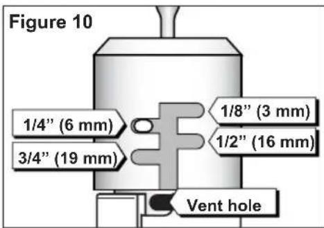
2- Rainfall Adjustment Cap - Adjusts the Sensor/Transmitter to signal the receiver when the accumulated rainfall reaches 1/8" (3 mm), 1/4" (6 mm), 1/2" (13 mm), 3/4" (19 mm) or 1" (26 mm).
3 - Vent Ring: Adjust "dry-out" rate.
4- Universal Mounting Bracket with Quick-Clip™ - Simplifies installation on rain gutter, or roof eaves, fences, etc. Sensor/Transmitter adjusts easily to the vertical position.
5 - Conduit Adapter: Alternate mounting option for conduit mount.
6- Antenna Wire - Straighten downward for maximum range.

Quick Start Installation Instructions
The following instructions are provided for the experienced installer.
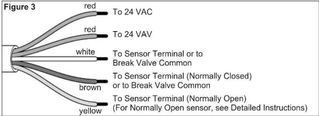
Refer to Figures 3–5 below.

When installing Sensor/Transmitter model RFS1000 for freeze detection, refer to additional freeze sensor installation information on page 8.
- Disconnect power to the irrigation system controller.
-
Always mount the Receiver FIRST, adjacent to the controller with either the provided stainless steel screws or double-sided foam tape.
-
Attach Receiver control wires to the sensor inputs OR to break the valve common:
-
Disconnect common valve wire and common pump/master valve wire (if present).
- Attach White wire to common wire(s) with a wire nut.
-
Attach Brown wire (only) to common terminal on controller.
-
Connect the Red wires to the controller's 24 VAC power source terminals.
-
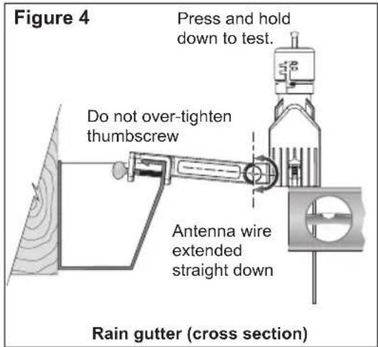
Straighten the Receiver antenna wire upward and the Sensor/Transmitter antenna wire downward.
-
While holding the Sensor/Transmitter at close range to the Receiver, press and hold the spindle to test the wiring. The Power, Signal and Sensor Status indicators should be ON.
-
Adjust the Rainfall Adjustment Cap to the desired rainfall activation amount.
-
Adjust the Vent Ring to the desired dry-out rate.
-
Mount the Sensor/Transmitter in an unobstructed location away from sprinklers.

Important: Reconfirm proper operation of the Sensor/Transmitter at the final mounting location.
flowchart
graph TD
    A["Central Component"] --> B["Red to 24 VAC"]
    A --> C["Red to 24 VAV"]
    A --> D["White to Sensor Terminal or to Break Valve Common"]
    A --> E["brown to Sensor Terminal (Normally Closed) or to Break Valve Common"]
    A --> F["yellow to Sensor Terminal (Normally Open) (For Normally Open sensor, see Detailed Instructions)"]

Detailed Installation Instructions
There are two main components of the Wireless RainSensor: the Receiver and the Sensor/Transmitter. The Receiver is installed adjacent to or within the cabinet of the irrigation system controller. The Sensor/Transmitter is installed outdoors where it is exposed to unobstructed rainfall.
Mounting the Receiver
- Always mount the Receiver FIRST, adjacent to the controller with either the provided stainless steel screws or double-sided foam tape. The connection wire cable is 20" (50 cm) long, so before attaching the Receiver, make sure the wires will easily reach the controller's connection terminals.
Wiring the Receiver
There are two parts involved in wiring the Receiver:
Part 1: Attach the Receiver control wires (similar to hard-wired sensors).
Part 2: Attach the low-voltage power wires to supply 24 VAC to the Receiver.
Part 1 - Control Wire Connection
The Receiver control wires are used to interrupt the common wire of the valves or they can be connected directly to the sensor input terminals of the controller (if provided).
-
Disconnect power to the controller.
-
Follow applicable wiring procedure A or B or C.

The following diagrams are representations only and do not depict actual controller layouts. Refer to the installation instructions provided with your controller for specific wire connection information.
A. Controllers with sensor inputs (with or without pump/master valve):
Refer to Figure 6. Find the controller sensor terminals (generally marked "Sensor", "SEN" or "S") and directly connect the White and Brown* wires to these terminals in any order. There may be a jumper wire or tab connecting the terminals that must be removed and/or a sensor bypass/control switch that must be activated.

4 Wireless RainSensor User's Guide
B. Controllers with no sensor inputs and no pump start or master valve:
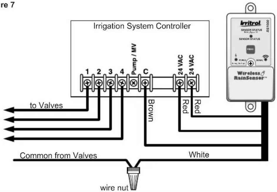
Refer to Figure 7. Disconnect the valve common wire from the controller's common terminal (generally marked "C", "Com", or "VC"). Join this wire to the White wire using a wire nut. Attach the Brown wire to the valve common terminal.

The yellow wire is not used in this application.
Figure 7
C. Controllers with pump start or master valve and no sensor inputs:
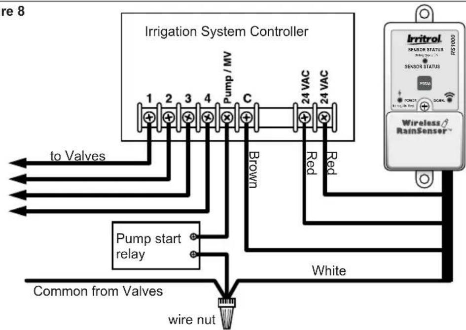
Refer to Figure 8. Disconnect all common control wires from the common terminal(s) of the controller (generally marked "C", "Com", or "VC"). Join these wires to the White wire using a wire nut. (Be sure to include the common wire from the Pump Start Relay in this connection). Attach the Brown wire to the common terminal.

The yellow wire is not used in this application.
Figure 8
flowchart
graph TD
    A["Irrigation System Controller"] --> B["1 2 3 4"]
    B --> C["Pump / MV"]
    C --> D["C"]
    D --> E["24 VAC"]
    E --> F["24 VAC"]
    G["Irritrol Sensor Status RS1000"] --> H["Power"]
    G --> I["Signal"]
    J["Wireless RainSensor"] --> K["Red"]
    J --> L["Brown"]
    M["Common from Valves"] --> N["Pump start relay"]
    N --> O["white"]
    P["wire nut"] --> Q["white"]
    R["to Valves"] --> S["1 2 3 4"]
    S --> T["Pump / MV"]
    T --> U["C"]
    U --> V["24 VAC"]
    V --> W["24 VAC"]
Part 2 - Power Wire Connection

The Receiver requires a nominal voltage of 24 VAC to operate. It should only be connected to an irrigation controller that uses a 24 VAC UL listed Class 2 transformer to supply power.

Caution: Do not connect the Receiver directly to 120/240 VAC power as this may result in irreversible damage. If you are in doubt, contact a qualified installer or electrician.
- Disconnect power to the controller.
- Follow applicable wiring procedure A or B.
A. Controllers with 24 VAC terminals:
Refer to Figure 8 (page 5). Terminals for 24 VAC power are present on the majority of controllers. Typical markings are "24 VAC", "24 and 24", "0 and 24" and "Hot Post and 24." Verify correct voltage, then simply attach the two Red power wires to these terminals leaving existing connections in place.
B. Controllers with no 24 VAC terminals:
Refer to Figure 9. On controllers that do not have 24 VAC terminals, connect the two Red power wires to the transformer's secondary 24 VAC power wires where they attach to the controller's circuit board.

This procedure will require a solder or wire-splice connection.
If you are unsure how to do this correctly, contact a qualified contractor or electrician for assistance.

Initial Receiver Testing
Reconnect power to the controller and verify the Receiver's Power Indicator is illuminated. Prior to mounting the Sensor/Transmitter, hold it at close range to the Receiver, then lightly press and hold the spindle. The Sensor Status indicator should illuminate and remain on until the spindle is released. The Signal Indicator should also illuminate during the test to verify good signal strength. If either indicator does not illuminate, recheck your wiring.
Verify that both antennas are fully extended and straight.
Installing the Sensor / Transmitter

If installing Wireless RainSensor model RFS1000 for freeze detection, please refer to additional instructions provided on page 8.
Testing Signal Strength at the Installation Site
The Receiver's Signal Indicator provides an indication of the strength of the last valid received signal. Prior to testing the Sensor/Transmitter in its final location, clear the Signal Indicator first so the test will represent the signal as received during the final check. To clear the Signal Indicator from previous tests, simply press the Smart Bypass button once, then once again to exit the bypass mode.
Prior to final placement, test the Sensor/Transmitter signal by lightly pressing and holding the spindle as described in "Initial Receiver Testing" on page 6.

If the location of the Sensor/Transmitter is not providing a valid signal to the Receiver, verify Sensor/Transmitter operation at close range and choose another mounting location. For additional information, refer to "Solving Reception Problems" on page 10.
Tip! If the Receiver is not visible to the installer, turn on a watering zone which is visible from the installation location and the activation of the
Sensor/Transmitter will shut off the "test" zone. Please note that the manual activation cycle of some controllers bypasses the sensor inputs.
You will need to run an automatic/timed watering program for these types of controllers.
Installation
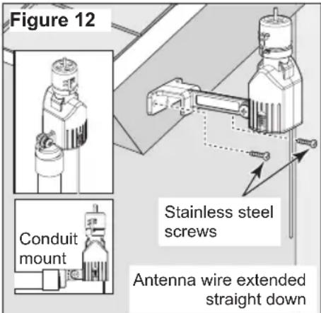
The Sensor/Transmitter should be mounted vertically with the antenna wire extending straight down. Avoid installations where the antenna wire would contact any metal object.
Mount the Sensor/Transmitter as close to the Receiver as possible to avoid interference of the wireless signal. The unit should be exposed to unobstructed rainfall, but not in contact with sprinkler spray or runoff from the roof.
Mounting to the outside edge of a rain gutter is simple with the Quick-Clip ^™ bracket.
See Figure 11.
The Sensor/Transmitter can also be mounted on any suitable solid structure using the supplied stainless steel screws. See Figure 12.
Wireless RainSensor with Freeze Sensor (model RFS1000)
Please follow the installation instructions for the basic Wireless RainSensor with the following considerations:
Install the Sensor/Transmitter as close to the controller and Receiver as possible. Although the Wireless RainSensor with Freeze option has a maximum range of 300', it is highly recommended that the units be installed no

greater than 100' apart. Install the unit in the coolest location of the controlled area, out of direct sunlight and avoiding direct southern exposure. A northeast to northwest shaded exposure works well.

Important: Avoid installation of the unit near a large heat storing object or heat producing device such as a dryer vent or chimney.

The installation and operation of a freeze sensor should be used in conjunction with frequent visual checks of your sprinkler system. While freeze sensors are designed to prevent inadvertent watering during near or below freezing conditions, there are instances in which manual intervention is required. Air temperatures may be above freezing while ground and vegetation temperatures remain below freezing. Operation of your sprinkler system during these conditions may cause icing. Very rapid air temperature changes may also result in inadvertent watering, should the timing of sprinkling coincide with rapid temperature changes.
The Sensor/Transmitter should be inspected for damage and manually tested regularly to ensure proper operation.

CAUTION: Visual checks and prudent manual watering suspension must be used in conjunction with any freeze sensor.
A freeze sensor should only be relied upon as an aid along with good watering practices including frequent visual checks. This device is not intended for farm/crop protection.
Wireless RainSensor Operation
Normal Operation
When the sensor activates due to sufficient rainfall or freezing temperatures (model RFS1000 only), the Sensor Status indicator will remain illuminated on the Receiver. After the rain sensor dries out, the controller will resume its normal watering schedule and the Sensor Status Indicator will turn off. The amount of rain required to activate the sensor can be set using the cap adjustment on the Sensor/Transmitter. Dry-out rates for the rain sensor vary dependent on ambient conditions such as temperature, sun exposure, humidity and wind – the same conditions your soil experiences.
Smart Bypass
Your Wireless RainSensor can be temporarily deactivated by using the built-in Smart Bypass button. Simply press this button once and the Sensor Status light will blink until the next time the Wireless RainSensor resets (dries out) - all automatically.
Pressing the Smart Bypass button again resumes the active state. Pressing the Smart Bypass button while the sensor is not active (dry or above freezing) will cause the sensor to ignore the next rain/freeze signal.
Power Down
In order to turn the Receiver OFF entirely, press and hold the Smart Bypass button until the Sensor Status indicator begins blinking rapidly (5–7 seconds). Release the Smart Bypass button and confirm the Power indicator goes out and flashes periodically. Simply press the Smart Bypass button once to turn the unit back on.
Receiver Learn Mode
If it becomes necessary to set the Receiver's address code to that of a new Sensor/Transmitter, press and hold the Smart Bypass button until the Status and Signal indicators blink in unison (7–10 seconds). Activate the corresponding Sensor/Transmitter at close range (by pressing down on the spindle) to change the existing Receiver code to that of the new Sensor/Transmitter. The indicators will stop blinking upon learning the new code. Pressing the Smart Bypass button again will exit the learn mode if no valid code is received.
Attention Required
When the Power indicator blinks, it indicates that one of the following conditions exists:
- The Sensor/Transmitter's battery is getting low and should be replaced when convenient. The Wireless RainSensor will function properly for some time after this indicator is present.
- If the batteries are good, a problem with communication is indicated. Relocating the Sensor/Transmitter may be necessary to provide a better signal.
Sensor Adjustment
Rainfall Adjustment
The Sensor/Transmitter can be adjusted to respond when it has detected nominal rainfall in the following amounts: 1/8" (3 mm), 1/4" (6 mm), 1/2" (13 mm), 3/4" (19 mm) or 1" (26 mm). Carefully rotate the Rainfall Adjustment Cap so the pins are positioned in the desired slots. Be sure to align the slots and pins properly, as this adjustment does not require excessive force. See Figure 10.
Vent Ring Adjustment
Closing the vent holes will slow the sensor dry-out rate. Uncovering the holes will accelerate the dry-out rate. For most installations, a fully-closed vent is appropriate.
Sensor/Transmitter Battery Replacement
- Remove the bottom cover of the Sensor/Transmitter by pressing down on the thumb-release lever on the side of the unit. Carefully slide the circuit board out. See Figure 13.
- Remove the battery cover and replace using two 3V CR2032 (or equivalent) batteries. Install with positive (+) side of the batteries facing up.
- Reassemble the unit in reverse order.
Changing the Sensor/Transmitter Code
The transmission code for the unit is identified by stickers on the Sensor/Transmitter and Receiver. Although, in most cases, even if two identical units are installed, unwanted activations would only occur if the two sensors are set for different rainfall amounts. However, the code may be manually changed as follows:
- Remove the bottom cover of the Sensor/Transmitter by pressing down on the thumb-release lever on the side of the unit. Carefully slide the circuit board out. See Figure 13.
- Identify the code wire loops (small black wire and white wire loops) and cut one or both loops using end-cutting pliers.
- Reassemble the Sensor/Transmitter and follow the procedures provided in "Receiver Learn Mode" above.

flowchart
graph TD
    A["Transmitter Code Wire Loops"] --> B["Device with Battery Cover"]
    B --> C["CR2032 Batteries"]
Troubleshooting
Signal Indicator (Installation Validation™)
The Signal Indicator provides instant signal strength feedback for the installer. The indicator always shows the strength of the last signal received. In order to clear this signal, simply press the Smart Bypass button once; pressing the button again will exit the bypass mode.
Improving Reception
The Wireless RainSensor operates under Part 15 of the FCC rules. This means that it has to comply with certain standards and is only allowed to transmit up to a certain power level. In rating transmitters of any form, typically a Line-of-Sight (LOS) value is used in order to show the relative effectiveness of a transmitter and allow a transmitter and receiver to be compared to one another using a fair (apples to apples) method. The Wireless RainSensor operates up to 300' (91.4 m) LOS - meaning in an open field, with no obstructions, the Sensor/Transmitter and Receiver pair will successfully communicate up to 300' (91.4 m) apart.
However, in almost all installations, there are obstacles between the Sensor/Transmitter and Receiver such as walls, floors, etc. The obstacles will all affect the transmitted signal and typically reduce the radiated power that will be read by the receiver. Different objects such as walls and floors affect the transmitted signal differently depending on the material composition, geometry, and thickness. Typically, most residential and light commercial construction materials do not reduce the effective transmitted signal enough to pose problems under normal installation conditions.
However there are some installations with very thick, dense walls, or that involve large amounts of radio frequency interference (electrical switching rooms etc.) where the effective range of the Wireless RainSensor may be greatly reduced.
Some helpful tips on mounting the Sensor/Transmitter and Receiver for the best Radio Frequency (RF) performance:
- Always try to keep the antennas straight and fully extended (straight up on the Receiver and straight down on the Sensor/Transmitter).
- Try to maintain a parallel orientation of one antenna to the other. Avoid installing either unit where the antennas are in close proximity to large metal objects.
- Attempt to mount the units as close together as possible to reduce the potential for interference or signal reduction. If the signal strength is not good in one location, try another location - even as little as a few feet of movement can change from a weak spot to a strong spot. Interior locations where cell phones or cordless phones have trouble with reception may indicate areas with poor RF signal transmission.
- If possible avoid an installation where the Sensor/Transmitter is located exactly above the Receiver. Move the Sensor/Transmitter slightly offset to one side. When the RF signal is passing through walls, keep in mind that it has less thickness to penetrate when it passes straight through the wall. In other words, passing diagonally through a wall increases its effective thickness. Because every installation is different, the ONLY guaranteed method to verify an installation is to physically TRY IT.
Specifications
Model Numbers:
RS1000 - Wireless RainSensor
RFS1000 - Wireless RainSensor + Freeze
Receiver Mounting Options:
Stainless steel screws and/or double-sided foam tape.
Sensor/Transmitter Mounting Options:
Quick-Clip ^™ rain gutter bracket and roof eaves/fascia mounting bracket with stainless steel screws.
Sensor/Transmitter Range:
Up to 300' (91.4 m) LOS (line-of-site).
Sensor Type:
Industry-standard hygroscopic disc stack with adjustable rainfall sensitivity.
Transmitter Battery Type:
(2) 3V cells - CR2032 (or equivalent).
Average Battery Life:
Five years
Operating Temperature Range:
-20°F to 120°F (-29°C to 49°C)
Receiver Power Input:
22–28 VAC/V dc, 100mA (from existing controller/timer with Class 2, UL-approved transformer).
Relay Contacts Output:
Normally Open (NO) and Normally Closed (NC) 3A at 24 VAC.
Receiver Controls:
Sensor Status Indicator, Signal Indicator, Smart Bypass Switch, Power Indicator with low battery/poor communication warning.
Radio Frequency Numbers:
RS1000 and RFS1000: 418 Mhz
RS1000-I and RFS1000-I: 433.92Mhz
RS1000 and RFS1000 Minimum Transmit Power: 0.0157 mW
Electromagnetic Compatibility
Domestic: This device complies with FCC rules Part 15. Operation is subject to the following two conditions: (1) This device may not cause harmful interference and (2) this device must accept any interference that may be received, including interference that may cause undesirable operation. This equipment generates and uses radio frequency energy and if not installed and used properly, that is, in strict accordance with the manufacturer's instructions, may cause interference to other devices or systems. It has been type tested and found to comply with the limits for a FCC Class B computing device in accordance with the specifications in Subpart J of Part 15 of FCC Rules, which are designed to provide reasonable protection against such interference in a residential installation. However, there is no guarantee that interference will not occur in a particular installation. To determine if your controller is functioning properly, verify that the controller is installed per the manufacturer's specifications and no inadvertent operational changes were made. If the problem persists, electromagnetic interference could be the problem. This can be determined by turning the equipment off and on and seeing if problems persist. The user is encouraged to try to correct the interference by one or more of the following measures:
Reposition or reorient the RainSensor with respect to the controller. Afterwards, reset by turning the device and host controller "ON/OFF" and allow the system to restart.
Plug the irrigation controller into a different outlet so that the irrigation controller and sensor are on different branch circuits.
If necessary, the user should consult the dealer or an experienced technician for additional suggestions. The user may find the following booklet prepared by the Federal Communications Commission helpful:
"How to Identify and Resolve Radio-TV Interference Problems". This booklet is available from the U.S. Government Printing Office, Washington, DC 20402. Stock No. 004-000-00345-4.
International: This is a CISPR 22 Class B product.
FCC ID: OF7WRS1
IC: 3575A-XXXXX

WARNING: Cancer and Reproductive harm – www.P65Warnings.ca.gov.
For more information, please visit www.toro.com/CAProp65.
Patent: www.ttcopats.com
Irritrol
5825 Jasmine Street
Riverside, CA 92504


- Introduction
- Component Overview
- Receiver (Figure 1)
- - Weather-resistant Cover:
- - Sensor Status Indicator:
- - Smart Bypass™ Button:
- - Power Indicator:
- - Signal Indicator: Indicates quality of last received signal.
- Sensor/Transmitter (Figure 2)
- Quick Start Installation Instructions
- Detailed Installation Instructions
- Mounting the Receiver
- Wiring the Receiver
- Part 1 - Control Wire Connection
- Controllers with sensor inputs (with or without pump/master valve):
- Controllers with no sensor inputs and no pump start or master valve:
- Controllers with pump start or master valve and no sensor inputs:
- Part 2 - Power Wire Connection
- Controllers with 24 VAC terminals:
- Controllers with no 24 VAC terminals:
- Initial Receiver Testing
- Installing the Sensor / Transmitter
- Testing Signal Strength at the Installation Site
- Installation
- Wireless RainSensor with Freeze Sensor (model RFS1000)
- Wireless RainSensor Operation
- Normal Operation
- Smart Bypass
- Power Down
- Receiver Learn Mode
- Attention Required
- Sensor Adjustment
- Rainfall Adjustment
- Vent Ring Adjustment
- Sensor/Transmitter Battery Replacement
- Changing the Sensor/Transmitter Code
- Troubleshooting
- Signal Indicator (Installation Validation™)
- Improving Reception
- Specifications
- Model Numbers:
- Receiver Mounting Options:
- Sensor/Transmitter Mounting Options:
- Sensor/Transmitter Range:
- Sensor Type:
- Transmitter Battery Type:
- Average Battery Life:
- Operating Temperature Range:
- Receiver Power Input:
- Relay Contacts Output:
- Receiver Controls:
- Radio Frequency Numbers:
- Electromagnetic Compatibility
Brand : Irritrol
Model : RS500
Category : Capteur de pluie sans fil