
RoboMaster EP - Educational robot DJI - Free user manual and instructions
Find the device manual for free RoboMaster EP DJI in PDF.


| Product Type | Educational Robot |
| Brand | DJI |
| Model | RoboMaster EP |
| Dimensions (unfolded) | 320 x 320 x 250 mm |
| Weight | Approx. 3.3 kg (with battery) |
| Power Source | Rechargeable Li-ion battery (6S 5200 mAh) |
| Charging Time | Approx. 90 minutes |
| Battery Life | Approx. 15 minutes of continuous operation |
| Main Functions | Modular design, programmable via Python and Scratch, AI vision, robotic arm, chassis movement, battle capabilities |
| Connectivity | Wi-Fi, Bluetooth, USB-C |
| Sensors | Camera, infrared, ultrasonic, gyroscope, accelerometer |
| Programming | Supports Scratch, Python, and RoboMaster app |
| Maintenance | Clean with dry cloth; avoid moisture; update firmware via app |
| Safety | Automatic shutdown on low battery, propeller guards, emergency stop |
| Spare Parts & Repairability | Individual components available (motors, sensors, wheels, battery); modular design for easy replacement |
| General Information | Designed for STEM education; supports RoboMaster SDK; includes built-in LED effects |
Frequently Asked Questions - RoboMaster EP DJI
User questions about RoboMaster EP DJI
0 question about this device. Answer the ones you know or ask your own.
Ask a new question about this device
Download the instructions for your Educational robot in PDF format for free! Find your manual RoboMaster EP - DJI and take your electronic device back in hand. On this page are published all the documents necessary for the use of your device. RoboMaster EP by DJI.
USER MANUAL RoboMaster EP DJI


Searching for Keywords
Search for keywords such as "battery" and "install" to find a topic. If you are using Adobe Acrobat Reader to read this document, press Ctrl+F on Windows or Command+F on Mac to begin a search.

Navigating to a Topic
View a complete list of topics in the table of contents. Click on a topic to navigate to that section.

Printing this Document
This document supports high resolution printing.
Using this User Manual
Legends

Warning Important Hints and Tips Reference

Before Use
The following tutorials and manuals have been produced to ensure you make full use of your ROBOMASTER ™ EP.
- Safety Guidelines and Disclaimer
- Quick Start Guide
- User Manual
Check to make sure all parts are included and prepare for assembly by reading the RoboMaster EP Quick Start Guide. Refer to this user manual for more information. Watch all tutorial videos and read the RoboMaster EP Safety Guidelines and Disclaimer before using for the first time.
Watching the Video Tutorials
Visit the official DJI website https://www.dji.com/robomaster-ep/video or go to the app and enter the Videos page to watch the tutorial videos for assembly and use. You can also assemble the EP according to the assembly guide in the RoboMaster EP Quick Start Guide.
Referring to the RoboMaster EP Programming Manual
The RoboMaster EP Lab offers hundreds of programming blocks that allow you to access features such as PID control. The RoboMaster EP Programming Manual provides instructions and examples to help users quickly learn programming techniques for controlling the EP.
Users can download the manual from the official DJI website https://www.dji.com/robomaster-ep/downloads.
Using an SDK
Open DJI SDK is available on the RoboMaster EP and includes multiple control interfaces for various embedded and extension modules as well as multiple output interfaces for video and audio streams. The EP supports USB, Wi-Fi, and UART connection and users are free to choose the method of connection based on the platform port.
Open DJI SDK greatly increases the expandability of the EP, offering the possibility to create customized functions. For more information, visit www.dji.com/robomaster-ep/downloads or robomaster-dev.rtfd.io.
Contents
Using this User Manual 3
Legends 3
Before Use 3
Watching the Video Tutorials 3
Referring to the RoboMaster EP Programming Manual 3
Using an SDK 3
Contents 4
Product Profile 6
Introduction 6
EP Diagram 6
Overview 9
Preparing 9
Modules and Functions 18
Using the RoboMaster App 18
Omnidirectional Chassis 22
Intelligent Controller 25
Camera 26
Speaker 26
Intelligent Battery 27
Robot LED Indicator Description 30
Gimbal 32
Blaster 34
Servo 36
Robotic Arm and Gripper 37
Power Connector Module 38
Infrared Distance Sensor (TOF) 41
Sensor Adapter 46
Straight Connecting Rod 49
Front Axle Extension Platform 50
Extension Building Block 50
EP and Third-Party Platforms 51
Gamepad (Not Included) 53
Operating Your EP 55
Checking Before Use 55
Powering on the Battery 55
Operating the Robot Using a Mobile Device 55
Gameplay 59
Solo Mode 59
Battle 61
Operating the Robot Using a Gamepad 64
Using a Computer and RoboMaster 65
Lab 66
Appendix 70
Specifications 70
Firmware Update 74
Calibrating the Robot 74
Setting the PWM Ports 75
Using the S-Bus Port 76
Programming Customizable UI 78
Product Profile
Introduction
The RoboMaster™ EP is an educational expansion set inspired by the DJI™ RoboMaster robot competition, which can be assembled into a Warrior or an Engineer form. The Warrior form offers comprehensive control and an immersive driving experience, thanks to the omnidirectional chassis, agile Mecanum wheels, flexible gimbal, and stable, low-latency image transmission in the first person view (FPV). Users can also target objects and compete against other robots using the blaster.
With the robotic arm, gripper, and SDK, the Engineer form provides comprehensive tutorials and practical scenarios for further learning, more varied competition, and more fun overall.
In addition, the RoboMaster EP provides power and communication ports for commonly used open source hardware platforms and multiple access points for sensors, so users can be even more creative with their educational expansion set.
EP Diagram
Warrior Form
- Chassis
- Right-Threaded Mecanum Wheel
- Chassis Front Armor (built-in Hit Detector)
- Left-Threaded Mecanum Wheel
- Chassis Left Armor (built-in Hit Detector)
- Chassis Rear Cover
- Gimbal
- Wide Infrared Unit
- Gimbal Armor (built-in Hit Detector)
- Pitch Motor
- Yaw Motor
- Intelligent Controller
- microSD Slot
- Infrared Distance Sensor
- Intelligent Controller
- Camera
- Blaster
- Launch Trajectory Light
- Narrow Infrared Unit
- Speaker
- Chassis Extension Platform
- Chassis Right Armor (built-in Hit Detector)
- Motion Controller

Engineer Form
- Chassis
- Right-Threaded Mecanum Wheel
- Chassis Front Armor (built-in Hit Detector)
- Left-Threaded Mecanum Wheel
- Chassis Left Armor (built-in Hit Detector)
- Chassis Extension Platform
- Servo
- Robotic Arm (1 of 2)
- Robotic Arm Connecting Rod #1
- Robotic Arm Connecting Rod #2
- Robotic Arm Connecting Rod #3
- Robotic Arm (2 of 2)
- Robotic Arm Endpoint Bracket
- Gripper
- Camera
- Intelligent Controller
- Intelligent Controller Antenna
- Rear Extension Platform

- Gel Bead Container
- Container Eject Button
- Chassis Rear Armor (built-in Hit Detector)
- Rear Armor Release Button
- Intelligent Battery
- Battery Eject Button

- Motion Controller
- Speaker
- Chassis Rear Armor (built-in Hit Detector)
- Rear Armor Release Button
- Intelligent Battery
- Battery Eject Button
Overview
The EP can be assembled into a Warrior or an Engineer form, both of which share the same omnidirectional chassis and Mecanum wheels. The EP offers comprehensive control and an immersive driving experience thanks to the omnidirectional chassis, agile Mecanum wheels, flexible gimbal, and stable, low-latency image transmission in first-person view (FPV).
The blaster of the Warrior provides high-level accuracy and stability thanks to the 2-axis gimbal while the launch trajectory light gives users a realistic and immersive experience. The Engineer uses a gripper and an agile robotic arm to grasp and move objects. The gripper and robotic arm are driven by two high-performance servos.
A customizable extension platform allows users to build and expand the EP any way they choose. The EP is also compatible with third-party building blocks, providing even more ways to learn and have fun.
Open DJI SDK is available on the RoboMaster EP and supports more than 50 programmable sensor ports. It is also compatible with third-party hardware, providing users with unlimited creative possibilities.
Preparing
Assembling the Robot
Refer to the RoboMaster EP Quick Start Guide.
Powering On the Robot
Follow the steps below to power on the robot:
- Press the rear armor release button to open the chassis rear armor.
- Install the intelligent battery into the battery compartment.
- Press and hold the power button to turn on the battery.
- Close the chassis rear armor.


2

Downloading the RoboMaster App
A. Search for the RoboMaster app in the App Store or on Google Play, or scan the QR code to download the app on your mobile device. B. Users can also download the RoboMaster software for Windows or Mac from the official DJI website to control the robot with a keyboard and mouse.
Windows: https://www.dji.com/robomaster_app
Mac: https://www.dji.com/robomaster_app


- Use your DJI account to log in to the RoboMaster app. • The RoboMaster app supports iOS 10.0.2 or later, or Android 5.0 or later. • The RoboMaster app supports Windows 7 64-bit or later, or macOS 10.13 or later.
- Before using the RoboMaster app with cellular mobile data, contact your mobile device data provider for the latest data information.
Connecting the Robot to the RoboMaster App
The robot must be connected to the RoboMaster app before use. Users can learn how to connect via Wi-Fi or via router on the Connection Mode page. Follow the prompts to connect to the app. Refer to the Connecting section for more information.

Initializing the Robot with the App
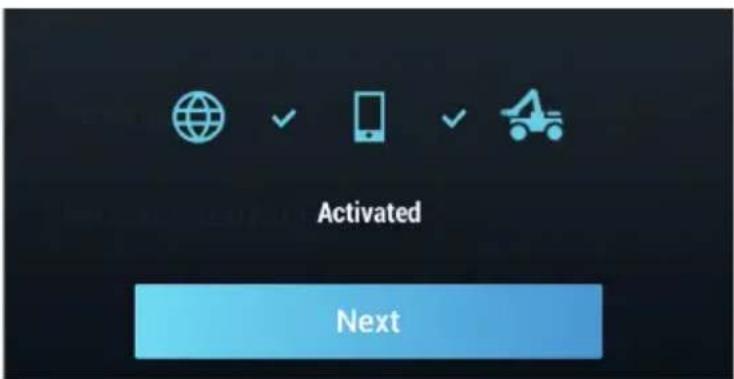
Activating the Robot
After connecting, use your DJI account to activate the robot in the RoboMaster app. Activation requires an internet connection.
- Start activation.

- Follow the prompts to complete activation.
Motor Addressing
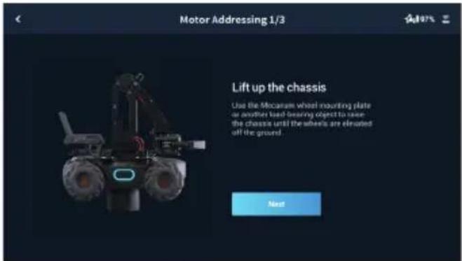
Motor addressing is required in the app before using for the first time. Follow the prompts to complete motor addressing.
- Start Motor Addressing.

- Lift the chassis and follow the prompts to rotate the Mecanum wheels in the order shown onscreen until all wheels have been rotated.

- Tap to test the Mecanum wheels one by one until all wheels have been tested.

- Motor addressing completed.
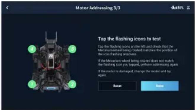

Motor addressing is required when a motor is replaced. Open the RoboMaster app, click Settings then System, and select Motor Addressing.
Armor Addressing
Armor addressing is required in the app when using the robot for the first time. Follow the prompts to complete armor addressing.
- Start Armor Addressing.
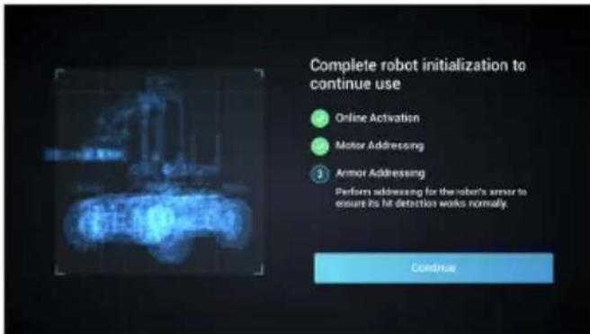
- Follow the prompts to tap on the armor plates in the order shown onscreen.

- Armor addressing completed.


Armor addressing is required when an armor module is replaced. Go to the RoboMaster app, click Settings, then System, and select Armor Addressing.
Robotic Arm Installation
The robotic arm must be installed in the app before using the Engineer form for the first time.
- Start Robotic Arm Installation.

- Follow the prompts to connect the left servo and right servo in turn.

- Calibrate the robotic arm.

Gripper Installation
The gripper must be installed before using the Engineer form for the first time.

Servo Installation
Make sure that the servos installed to the EP have different IDs and each ID ranges from 1 to 3. Otherwise, users must change the servo ID. Follow the prompts to complete servo installation.
- Start Servo Installation.

- Follow the prompts to connect the servos in turn.

- Follow the prompts to select module numbers for the servos until each servo has its unique number.


- Servos can be connected in series. • After removing the robotic arm, the two servos on the robotic arm can be controlled separately.
Infrared Distance Sensor Installation
Follow the prompts to complete infrared distance sensor installation. If more than one infrared distance sensor is installed on the robot, each sensor must be set with a different ID.
- Start Infrared Distance Sensor Installation.

- Follow the prompts to connect the infrared distance sensors in turn.

- Follow the prompts to select module numbers for the infrared distance sensors until each sensor has its unique number. The robot supports the installation of multiple infrared distance sensors and users can select the ID accordingly.

Sensor Adapter Installation
The preset number for each sensor adapter is 1. Make sure that the sensor adapters installed on the robot have different IDs. Otherwise, users must change the sensor adapter ID. Follow the prompts to complete sensor adapter installation.

Modules and Functions
Using the RoboMaster App
With the dedicated RoboMaster app, users can access rich educational resources and several gameplay modes. The app can be used with a touchscreen or a gamepad and is available on iOS, Android, Windows, and Mac. Users on different platforms can even play together at the same time. Users can also write programs easily and apply them or share with friends instantly using the RoboMaster app. This section uses the RoboMaster app on iOS as an example. The specific interface may vary depending on the device used.
RoboMaster App Main Page

1. Account
Tap to log in and log out of your account, modify your avatar, name, and gender information. An internet connection is required in order to log in.
Check your total driving distance, total driving time, written code, coding time, the number of completed courses in "Road to Mastery", and the highest points in Target Practice.
Tap MasterBoard to view the top 100 users for total driving distance, total driving time, total code written, total coding time, and target practice score.
2. Media Library
Tap to view videos and photos.
3. Guide
a. Product Support: Tap to enter the official DJI product support page.
b. Maintenance Support: Tap to enter the official DJI Repair Center page.
c. User Manuals: Tap to enter the official DJI user manual download page.
d. Vision Markers: Tap to enter the official Vision Marker download page.
e. Online Support: Tap to contact the official RoboMaster Series Online Assistance service.
f. Feedback: Tap to fill out a feedback form.
g. Videos: Tap to enter the official DJI tutorial video page.
h. Forum: Tap to enter the official DJI forum page.
4. Announcements
Announcements regarding topics such as RoboMaster products, competitions, and developer programs.
5. Connect
The EP must be connected with the app. Tap to see a guide on how to connect via Wi-Fi or router.
Connection via Wi-Fi
Users can enter both Solo and Battle mode when connecting via Wi-Fi.
Follow the steps below to connect:
(1). Slide the mode switch on the intelligent controller to the desired position and power on the robot.

(2). Run the RoboMaster app, go to Wi-Fi settings on the mobile device, select the Wi-Fi name (RMEP-XXXXXX) shown on the sticker on the body of the robot, and enter the password. The default password is 12341234.

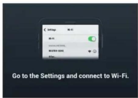
(3). Wait for the robot and the app to connect. The robot will emit a sound once connected.
Resetting the Password
Make sure the mode switch on the intelligent controller is slid to the Connection via Wi-Fi position, and press and hold the connect button for five seconds to reset the password.

Resetting the Password
Users can enter both Solo and Battle mode when connecting via router.
Follow the steps below to connect:
(1). Slide the mode switch on the intelligent controller to the desired position and power on the robot.
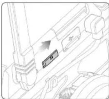
(2). Open the RoboMaster app, go to Wi-Fi settings on the mobile device, connect to a router, and input the Wi-Fi password of the router to generate a QR code.

(3). Press the connect button on the intelligent controller and use the camera of the robot to scan the QR code. The robot will connect to the router automatically.

6. Robot Model Selection
Select the robot model as RoboMaster S1 or RoboMaster EP.
7. Settings
Robot, Extension Module, Connect, Display, Control, and System can be found in the Settings page.
a. Robot
Users can check the status of each individual component of the robot. When a component is abnormal, the corresponding part will be displayed in red with more detailed information provided on the right side of the screen.
b. Extension Module
Users can install a robotic arm, gripper, servo, infrared distance sensor, or sensor adapter on the Extension Module screen. Users can also check the installation status of these modules.
c. Connect
Displays the connection status of the robot. When connected, users can also check the Channel Display, Wi-Fi Name, Wi-Fi Password, and also modify Wi-Fi information.
d. Display
Users can set the LED Display Color, FPV Hit Point Bar, FPV Screen Adaptation, FPV Gimbal Angle Readout, Video Resolution, Anti-Flickering, and 3D Quality.
e. Control
Users can set the Speed, Firing Mode, Sight Type, Sight Calibration, Control Mode, Control Sensitivity, Gimbal Gyro Control, Gyro Sensitivity, and Vibration. The Speed and Firing Mode settings only apply to the Warrior form.
f. System
The following actions can be performed under the system settings:
Power off the robot.
Enable programming sleep mode.
Check the app version and set the app language.
Set the voice language and the volume of the robot.
Perform a firmware update, check what firmware has been downloaded, and check the firmware version.
Perform armor addressing, motor addressing, and gimbal and chassis calibration.
Replay the beginner guide.
Check the remaining space on the SD card and format the SD card.
Enable GPS information, check the device information, and read about the terms of use and the DJI Product Improvement program.
8. Solo
Tap to enter Solo mode. Users can connect either via Wi-Fi or router. Refer to the Gameplay section for more information.
9. Battle
Tap to enter Battle mode. Users can connect either via Wi-Fi or router. When using multiple EPs, users must connect via the same router. Refer to the Gameplay section for more information.
10. Lab
Road to Mastery: Road to Mastery offers project-based courses that enhance users' understanding of programming languages, from robotics applications to AI technology, with
different projects for both beginners and experts.
DIY Programming: Both Scratch and Python are available for programming.
RoboAcademy: RoboAcademy offers a curriculum of videos and programming guides. In-depth videos introduce robotics in simple but fascinating ways, giving users insightful and relevant scientific knowledge. The RoboMaster EP Programming Manual offers detailed explanations of various blocks and modules, making it easier for users to understand the fundamentals of EP programming.
Omnidirectional Chassis
Introduction
The chassis is an omnidirectional motion platform based on Mecanum wheels, which can move forward, traverse, skew, rotate, or perform a combination of these movements simultaneously.
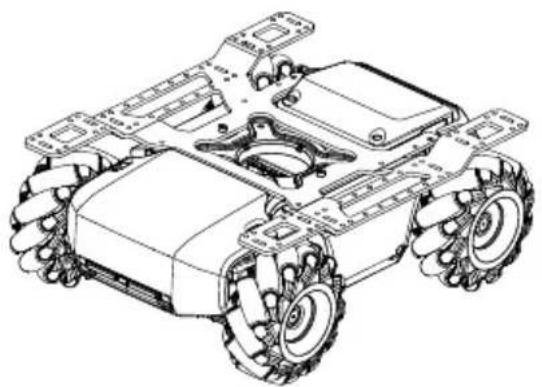

Avoid crashing into any objects at high speed.
Motion Controller
Overview
The motion controller is the core module for chassis movement, providing a rich external module interface for video transmission and connecting the gimbal, battery, armor, and motors. It also integrates an omnidirectional wheel motion control algorithm, power management system, motor management system, and a chassis management system.


1. CAN Bus Port
CAN Bus port used for armor module connection.
2. Power Port
Power port used for intelligent battery connection. Note that this interface contains the battery management system. Avoid unplugging the power port unless necessary.
3. M BUS Port
Motor port used for motor connection.
4. CAN BUS Port
Gimbal port used for gimbal connection.
5. Micro USB Port
Supports connection and communication in SDK USB RNDIS.
6. UART Port
UART port is an extension port, used for programming and supports SDK connection.
7. PWM Output Port
The motion controller enables the duty cycle to be set through the Scratch or Python program using the PWM output port.
8. S-Bus Port
Controls signal reception and is used to connect a remote controller receiver that supports SBUS protocol.
9. M0 Port
Used for servo and gripper connection.
10. LED indicator
Used to indicate the status of the motion controller.
| LED indicator Motion controller status | ||
| Blinks blue slowly | B...... | Working normally |
| Blinks yellow slowly | Y Running autonomous program | |
| Blinks green quickly | IMU calibration successful | |
| Blinks red quickly | R...... | IMU calibration failed |
| Solid yellow IMU is calibrating | ||
| Solid white Firmware updating | ||
| Blinks red, green,and blue alternatively | RG No-attitude information input | |
| Blinks red slowly | R...... | Stop Mode*Stop mode may occur in the following situations:a. Motion controller is disconnected from or cannot communicate with motor.b. EP cannot move due to the motor hardware abnormality.c. Motion controller cannot communicate with the gimbal.d. Motion controller cannot communicate with the remote controller.e. Abnormal motion controller attitude.f. Motion controller cannot communicate with the battery. |
* Stop mode warning prompts will display in the app. Go to Settings then System to check the corresponding error.

- Connect the black, orange, and red cables to the ports of the corresponding color.
- Make sure the motion controller is properly installed before use and the screws on the chassis rear cover are locked.
- After each reinstallation of the motion controller, calibrate the robot if prompted to do so in the RoboMaster app. Refer to the Calibrating the Robot section for more information.
- To avoid dislodging the motion controller when removing the rear chassis cover, lift the cover carefully before removing.
Mecanum Wheel
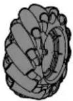
The Mecanum wheel is a commonly used robotic omnidirectional chassis moving solution, which is divided into two types: left-threaded and right-threaded. The four-wheeled chassis requires two pairs of Mecanum wheels.
 |  |  |  |
| Left-threaded Mark | Left-threaded Mecanum Wheel | Right-threaded Mark | Right-threaded Mecanum Wheel |
When installing, you can check the left-threaded mark or right-threaded mark on the bottom of the chassis, and install the left-threaded or right-threaded Mecanum wheel accordingly.

Motors and ESCs
RoboMaster EP features an M3508I brushless motor and ESC with a maximum speed of 1000 rpm for brushless motors.

- Make sure the connections between all motors and motion controller are stable.
- If the motor does not rotate freely, immediately power off the EP and check the motor.
- DO NOT touch or let your hands or body come into contact with the motors, motors mounting plate, or inside of Mecanum wheel immediately after powering off the robot.
Armor Modules
A total of four armored modules are installed on the four sides of the chassis, which protect the internal structure of the robot.
All armor is equipped with a hit detector, which is used to detect where the EP is struck by the gel beads and sends feedback to the intelligent controller to deduct hit points from the corresponding hit point bar.
Each hit detector module is represented by an LED light and is visible under the armor module.
Intelligent Controller
The intelligent controller is integrated with multiple systems including a video transmission system, game system, and Scratch programming system. It supports six smart modules, including line recognition, vision marker recognition, person recognition, clap recognition, gesture recognition, and EP robot recognition.
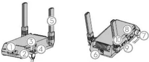
1. microSD Slot
Compatible with a microSD card that can read and write faster than 10 MB/s, supporting up to 64 GB.
2. Camera Port
Used to connect to the camera.
3. Speaker Port
Used to connect to the speaker.
4. Autonomous Program Button
Scratch programs written by the user can be set as autonomous programs, which can be loaded directly onto the EP. Press the Autonomous Program Button to run the program.
5. Antennas
For optimal Wi-Fi connection, set the intelligent controller antennas at 90°.
6. Secondary Camera Port
A reserved port used for switching to the second camera view.
7. CAN Bus Port
Used to connect to the gimbal.
8. Micro USB Port
Used to connect to the computer.
9. Connect Mode Switch
Used to switch between connecting via Wi-Fi or a router.
10. Connect Button
The connect button functions differently when connecting via Wi-Fi or router.
Connection to Wi-Fi: Once the Wi-Fi password is forgotten, press and hold this button for five seconds to reset the Wi-Fi password.
Connection to Router: When scanning the QR code with the EP to join a network, press this button first.

• DO NOT pull on the antenna.
- If the intelligent controller antenna is damaged, the performance of the EP will be affected. Contact DJI if the antenna is damaged.
Camera
The EP camera features a 1/4-inch sensor with 5 million pixels and a FOV of 120°, allowing users to control the robot from a first-person perspective.
Clean the lens regularly to avoid blurring or halos. Use a special lens cleaner to make sure that there is no foreign matter on the lens after cleaning and that it does not damage the lens.

- Camera Lens
- Microphone
- Camera Port
Used to connect the camera to the intelligent controller.

• DO NOT expose the camera to liquids or immerse in water.
• DO NOT store the camera in a humid place.
• DO NOT touch the lens.
• If the camera is wet, wipe it with a dry soft cloth.
Speaker
The EP speaker connects to the intelligent controller via a 2.5mm device with a power rating of 2 W.


Make sure the speaker is properly installed and does not obstruct gimbal movements.
Intelligent Battery
The EP intelligent battery has a capacity of 2400 mAh, a voltage of 10.8 V, and a variety of power management functions.
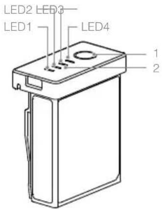
- Power Button
- Battery Level Indicator
Intelligent Battery Functions
- Battery Level Display: LEDs display the current battery level.
- Auto-Discharging Function: The battery automatically discharges to below 70% of total power when it is idle for more than 10 days to prevent swelling. To exit the idle state, press the power level button to check the battery level. It takes approximately one day to discharge the battery to 60%. It is normal to feel moderate heat emitting from the battery during the discharge process.
- Balancing Function: Automatically balances the voltage of each battery cell when charging.
- Overcharge Protection: Charging stops automatically when the battery is fully charged.
- Temperature Protection: The battery only charges when the temperature is 5 to 45°C (41 to 113°F).
- Overcurrent Protection: Battery stops charging when high amperage is detected.
- Over-Discharge Protection: To prevent serious damage to the battery, the current output will be cut off when the battery cell is discharged to 2.5 V and not in use. To extend operating times, overcharging protection is disabled as batteries discharge during usage. In this instance, a battery voltage below 1 V may cause a safety hazard such as a fire when charged. To prevent this, the battery will not be able to charge if the voltage of a single battery cell is below 1 V. Avoid using any batteries matching this description. Avoid over-discharging to prevent permanent battery damage.
- Short Circuit Protection: Automatically cuts the power supply when a short circuit is detected.
- Battery Cell Damage Protection: The RoboMaster app displays a warning message when a damaged battery cell is detected.
- Sleep Mode: Sleep mode is entered to save power when the battery is not in use. If the battery is turned on without being connected to the EP, the battery will turn off after five minutes. When the battery power is less than 5%, it will automatically enter sleep mode after six hours to prevent over-discharging. If this occurs, press the battery power button once, and the battery can be charged to wake up.
- Communication: Battery voltage, capacity, current, and other relevant information is provided to the gimbal.

Read the user manual, disclaimer, and descriptions on the battery before use. Users take full responsibility for all operations and usage.
Charging the Intelligent Battery
The battery charger is designed for charging batteries for the EP. Lift the battery charger cover and insert the intelligent battery. Connect the battery charger to a power outlet (100-240 V, 50/60 Hz).

Charging Time: Approx. 1 hour and 30 mins*
* The charging time was tested in a lab environment using a new intelligent battery, and should be taken as a reference only.

- Before using for the first time, charging is required to wake up the battery. • Make sure the battery is fully charged before each use.
- When the charger is not in use, keep the battery charger covered in order to prevent the metal terminals from being exposed.
Status LED Descriptions
| Battery Level Indicators while Charging (Battery) | ||||
| LED1 | LED2 | LED3 | 4 Battery Level | |
| 0%~50% | ||||
| 50%~75% | ||||
| 75%~100% | ||||
| Fully Charged | ||||
| Battery Level Indicators for Battery Protection | ||||
| LED1 | LED2 | LED3 | LED4 Blinking Pattern Battery Protection Item | |
| LED2 blinks twice per second Over current detected | ||||
| LED2 blinks three times per second Short circuit detected | ||||
| LED3 blinks twice per second Over charge detected | ||||
| LED3 blinks three times per second Over-voltage charger detected | ||||
| LED4 blinks twice per second Charging temperature is too low (<0°C) | ||||
| LED4 blinks three times per second Charging temperature is too high (>40°C) | ||||
After any of the protection issues are resolved, the battery level indicator will power off. Unplug the intelligent battery from the charger and plug it back in to resume charging. Note that you do not need to unplug and re-plug the charger in the event of a charging temperature error. Charging will resume when the temperature falls within the normal range.

DJI is not responsible for damage caused by third-party chargers.
Mounting the Intelligent Battery
When in use, open the rear armor cover and insert the battery into the battery compartment.


- Make sure the battery is securely installed. Otherwise, the battery may fall out or have insufficient contact, which can lead to loss of battery information.
- Make sure to press the battery eject button before removing the battery.
Using the Intelligent Battery
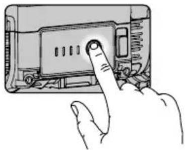
Checking the Battery Level
Press the battery level button once to check the battery level.

The battery level indicators will also show the current battery level during discharging. The indicators are defined below.
LED is on. LED is flashing. LED is off.
Battery Level
| LED1 LED2 LED3 LED4 Battery Level | ||||
| 88%~100% | ||||
| 75%~88% | ||||
| 63%~75% | ||||
| 50%~62.5% | ||||
| 38%~50% | ||||
| 25%~38% | ||||
| 13%~25% | ||||
| 0%~13% | ||||
Powering On/Off
Press and hold the power button for more than two seconds to power on or off.
Low-Temperature Notice
- The performance of the intelligent battery is significantly reduced at temperatures below 5°C (41°F). Make sure that the battery is fully charged and the cell voltage is at 4.2 V before use.
- In extremely cold weather, the battery temperature may not be high enough even after warming up. In these cases, insulate the battery as required.
- To ensure optimal performance, keep the core temperature of the Intelligent Battery above 20°C (68°F) when in use.
Robot LED Indicator Description
The robot features LED indicators on the four armor modules of the chassis body and on both sides of the gimbal, which indicate the current status of the robot.

- Gimbal LED indicator, eight on each side.
- Chassis LED indicator, one for each armor.
LED Indicator Description
Robot Status | Gimbal LED Indicator | Chassis LED Indicator
Battery Power
Power on Robot: Blinks cyan counterclockwise | Solid cyan
Power off Robot: Custom color powers off | Custom color powers off
Connect
Robot operating normally, not connected to app: Pulses white | Pulses white
Robot and app connecting: Blinks cyan | Blinks cyan
Robot and app connecting Blinks cyan Blinks cyan
Robot operating normally, connected to app
Solid custom color
Firmware update
Updating firmware: white bars indicating progress, solid white
Firmware update failed: solid red
Solid red
Firmware update successful
Solid cyan
Solid cyan
| Solo mode | ||
| Entering Solo mode | Custom color blinks counterclockwise and then solid default color | Solid custom color |
| Entering Follow mode | Custom color blinks counterclockwise continuously | Solid custom color |
| Battle mode | ||
| Entering Battle mode | Custom color blinks counterclockwise and then solid team color | Solid custom color |
| Hit detected Blinks red once Blinks red once | ||
| Defeated | Custom color blinks randomly and then powers off | Custom color blinks and then powers off |
| Revived | Custom color blinks randomly and then solid custom color | Custom color blinks and then solid custom color |
| Victory Solid custom color Solid custom color | ||
| Hit Point Bar fully restored | Custom color blinks counterclockwise and then solid custom color | Custom color blinks and then solid custom color |
| Used Mystery Bonus | Custom color blinks counterclockwise three times | Solid custom color |
| Hit by Mystery Bonus | Custom color blinks until Mystery Bonus effect ends | Custom color blinks until Mystery Bonus effect ends |
* The custom color is set under LED Display Color in the Display settings in the app. In Battle mode, the custom color is assigned automatically. The user who is the host is assigned purple.

When changing the custom color, the LEDs on both the chassis and the gimbal will change color.
Gimbal
Introduction
The Warrior form is equipped with a 2-axis gimbal to provide a stable platform for the blaster and the camera. When the Warrior form is in motion, the blaster remains stable and can launch gel beads or emit an infrared beam, and at the same time provides a smooth FPV experience for the user.

1. Yaw Motor
Controls the yaw of the gimbal and works in conjunction with the pitch motor to help the blaster aim at targets and achieve stabilization.
2. Pitch Motor
Controls the pitch of the gimbal and works in conjunction with the yaw motor to help the blaster aim at targets and achieve stabilization.
3. Gimbal Armor
Includes built-in LEDs, the color of which can be customized in the app.
4. Wide Infrared Unit
Emits wide-angle infrared beams and detects infrared beams emitted by other robots.
5. Gimbal Arm Shaft
Supports the blaster and the intelligent controller.
6. CAN BUS Port
Connected to the blaster.
7. CAN BUS Port
Connected to the intelligent controller.
8. CAN BUS Extension Port
Used to connect an infrared distance sensor.
Using the Gimbal
After powering on the robot, DO NOT cover or touch the gimbal and avoid moving the chassis so that the self-test can be completed smoothly. DO NOT apply external force to the gimbal after the gimbal is powered on.
The default mode of the robot is Chassis Lead mode. The user can control the angle of the gimbal on both the pitch and yaw axes. The pitch axis control range is -20° to +35° and the yaw axis control range is ±250°. The maximum rotation speed of the gimbal is 540°/s.
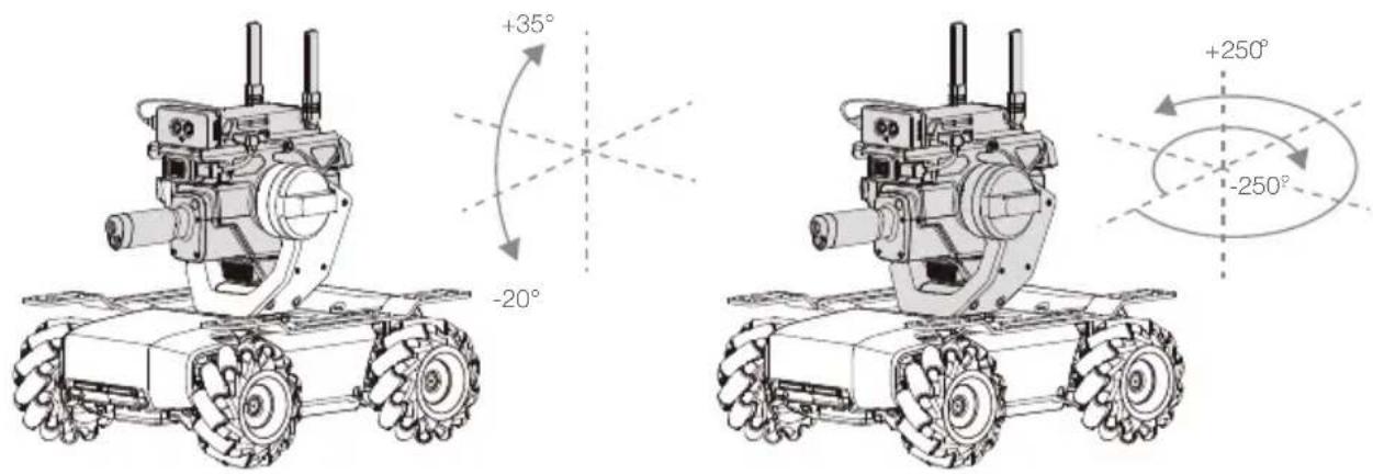

- The gimbal and gimbal connector are delicate. Handle with care and DO NOT touch the gimbal connector.
- When powering on the gimbal, DO NOT touch the gimbal to avoid being injured by the rotating shaft.
- When the gimbal is in use, DO NOT touch the metal parts on the inner side of the pitch motor as it may become hot.
- Make sure the unused port on the side of the gimbal arm shaft is covered. Otherwise, it may become filled with foreign objects and short-circuit.
Blaster
Introduction
Blaster applies to the Warrior form. Before using the blaster, make sure to wear the safety goggles provided by DJI.

The blaster must be mounted onto the gimbal and can be used in two applications:
- With a gel bead container to launch gel beads: The launch speed of the gel beads from the blaster is about 26 m/s, the controllable launch frequency is 1-8 rounds/s, and the maximum launch frequency is up to 10 rounds/s.
- The blaster integrates a narrow infrared unit with an effective range of up to 6 m indoor lighting: Within the effective range, the effective angle gradually decreases with increasing distance, and the effective shot width varies from 40° to 10°.

- Trajectory
- Launch Trajectory Light
- Narrow Infrared Unit
- Container Eject Button

• DO NOT aim the blaster at people or animals when launching the gel beads.
• DO NOT point the launch trajectory light at the eyes of people or animals.
Preparing the Gel Beads
The EP blaster can launch gel beads. The gel beads must be soaked in water in advance. Follow the steps below to soak the gel beads.
- Use the gel bead bottle cap to measure the number of gel beads. One gel bead bottle cap holds approximately 500 rounds.
- It is recommended to soak the gel beads in 1,000 ml of purified water for four hours at room temperature before use. The soaked gel beads have a diameter of 5.9-6.8 mm and a mass of 0.12-0.17 g.


The size of soaked gel beads may vary if water of different quality is used. Soak according to the specifications to avoid blocking the Blaster.
Loading the Gel Beads
Follow the steps below to load the gel beads. The loading capacity of the gel bead container is approximately 430 rounds. Load the required number of gel beads according to the usage.
![graph TD A["Step 1: Internal component"] --> B["Step 2: Internal component"] B --> C["Step 3: Internal component"] C --> D["Step 4: Internal component"] D --> E["Step 5: Internal component"]](/content/2026/06/1364284/images/3e54fd4ae0faaeb1402b31d3ecd0167505c59f2bcadcdd4ac876129561ff5786.jpg)

• After each use, make sure to clear the gel beads in the gel bead container to prevent accidental injury. • DO NOT swallow the gel beads. • Make sure to keep the gel beads out of reach of children and animals. - Do not freeze gel beads that have been soaked during use. Otherwise, the gel beads will harden and block the blaster or may cause injury.
Installing/Removing the Gel Bead Container
Follow the steps below to install or remove the gel bead container.


Press the container eject button before removing the gel bead container.
Servo
Introduction
As a propulsion driver for the RoboMaster EP, the servo supports customized control abilities through the programming interfaces of the EP. The servo ensures minimal gear backlash, high control accuracy, and large output torque. Other uses include powering the robotic arm and supporting the DC gear motor mode, which allows users to build lifting structures.
The servo uses RS485 bus mode and is compatible with PWM mode. When the servo is used to drive the robotic arm, the system switches to RS485 bus mode automatically. When used independently, the servo can operate in either RS485 bus mode or PWM mode. The system automatically switches according to the input signal.

Servo PWM Port
The port pin is shown below:


| 1 2 3 | 4 | ||
| 485A/PWM 485B VCC-12V GND | |||
The servo supports two control modes: angle mode and rate mode. The PWM signal has a frequency of 50 Hz and a duty cycle ranging from 2.5% to 12.5%.
Control Mode Duty Cycle Control Range
Angle Mode 2.5% to 12.5% 0° to 360°
| Rate Mode | 2.5% to 7.5% 49 to 0 rpm |
| 7.5% to 12.5% 0 to -49 rpm |
LED Indicator Description for Servo
The LED indicator is used to indicate the status of the servo. Details are as follows:
| LED Indicator Servo Status | ||
| Solid green |  | Working normally |
| Blinks red rapidly |  | Self-test error* |
| Blinks green and yellow alternatively |  | Overload protection** |
| Blinks red and yellow alternatively |  | Stalled*** |
| Blinks green rapidly |  | The servo is selected in the RoboMaster app |

- When in use, DO NOT touch the servo to avoid injury.
- DO NOT hit the servo. Otherwise, it may reduce the service life of the servo or even lead to permanent damage.
- When the servo overload warning prompts appear in the app multiple times, stop the operation immediately and check the operation and the structure of the robotic arm or servo.
- When mounting the servo onto the robotic arm, use the programming interface with caution to avoid affecting the limit structure of the robotic arm.
- When the servo is in PWM mode, its status cannot be displayed on a computer. The current status of the servo can be retrieved from the LED indicator.
Robotic Arm and Gripper
Introduction
The robotic arm of the EP supports precise FPV control and can be used with the gripper. Grab and move objects by controlling the robotic arm and gripper in first person view (FPV) in the RoboMaster app.

Use Instructions
DO NOT apply external force to the robotic arm or gripper when they are in use.
The movement range of the robotic arm and the grip distance of the gripper can be controlled. The horizontal movement range of the robotic arm is 0-0.22 m while the vertical range is 0-0.15 m. The grip distance of the gripper is 10 cm.

• To avoid injury, DO NOT touch the robotic arm or gripper when they are in use. - DO NOT hit or damage the robotic arm or gripper. Otherwise, the performance may be negatively affected or the servo may become abnormal. - Clean foreign objects like droplets and gel bead residue in a timely manner. Otherwise, the surface of the structure may corrode.
Gripper PWM Port
The port pin is shown below:

| 1 2 3 | 4 | ||
| 485A/PWM 485 | B VCC-12V GND |
The gripper supports torque control mode. The PWM signal has a frequency of 50 Hz and a duty cycle ranging from 2.5%-12.5%. 2.5%-7.5% corresponds to the gripper's closing force (Max-0), and 7.5%-12.5% to its opening force (0-Max).
Power Connector Module
Introduction
A power connector module can connect and power third-party hardware, offering multiple ports to connect hardware and create custom programs and applications.

- 12V Power Input Port
The input voltage is 9.6-12.6 V.
- CAN Bus Port
Connect with CAN bus cable.
- 5V/2A Power Output Port
The output voltage is 5 V and supports a current output of up to 2 A.

- 5V/4A Power Output Port
The output voltage is 5 V and supports a current output of up to 4 A.
- LED Indicator
Indicates the status of the power connector module.
- 12V Conducting Power Output Port
Conducts power along with the 12V power input port.

If both 5V power output ports are used, the module supports a current output of up to 4 A.
Mounting the Power Connector Module
- Unplug the power cable of the motion controller.
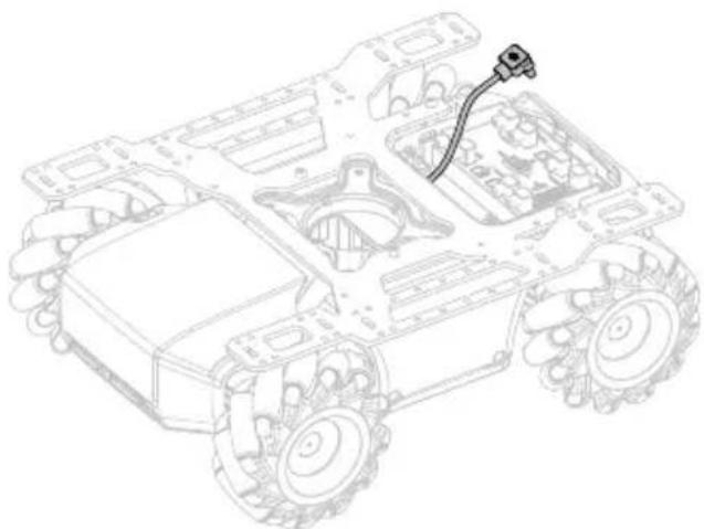
- Connect the power cable and a Y-cable.

- After connecting a Y-cable to the motion controller as shown below, place the power cable on the chassis and pull the XT30 power cable of a Y-cable through the chassis middle frame to the chassis cabin.

- As shown below, connect the A end of a 12cm data cable to the motion controller and pull the B end through the chassis middle frame to the chassis cabin.

- As shown below, connect the XT30 power cable in the chassis cabin to the 12V power input port and the B end of the 12cm data cable to the CAN bus port of the power connector module. Secure the module at the chassis cabin.
If the EP is in a Warrior form, two 12cm data cables of the gimbal need to connect to the CAN bus port of the power connector module.

LED Indicator Description for Power Connector Module
The LED indicator is used to indicate the status of the power connector module. Details are as follows:
| LED Indicator Power Connector Module Status | ||
| Solid white | W — | Normal power input and 5V output |
| Solid red | R — | Normal power input, but 5V output has an overcurrent or is short-circuited |
| Off Abnormal powerInput | ||
Infrared Distance Sensor (TOF)
Introduction
The infrared distance sensor calculates the distance between a sensor and an object by measuring the time it takes an infrared light to reach the object and return to the sensor. The infrared distance sensor consists of an illumination unit, optical receiver, and signal processing system. The illumination unit emits a beam of modulated near-infrared light. When the beam of light is reflected by an object, the reflected beam will be directed through the optical receiver and converted into a current. The receiver transmits the generated electric signal to the signal processing system for demodulation and distance calculation.
The infrared distance sensor has a field-of-view (FOV) of 20° and measures the distance of objects within the FOV. If there are multiple objects at different distances inside the FOV, the measured distance will be within the range of the nearest object and the farthest object. The actual measurement data is related to the size ratio and reflectivity of the object. Users can learn more about the infrared distance sensor through practice.
With a measurement range of 0.1-10 meters, the infrared distance sensor accurately measures within a margin of error of 5%. The addition of programmable modules in Scratch also provides reliable distance measurement information. This enables the EP to sense its environment and avoid obstacles, deepening users' understanding of advanced autonomous driving principles.


1. CAN Bus Port
Connect to the robot via a CAN bus cable.
2. Serial Port
a) The serial signal supports a level of 3.3 V. b) The input voltage is 5-12.6 V.
Mounting the Infrared Distance Sensor
In addition to the gimbal, the infrared distance sensor can also be mounted on the chassis extension platform with the use of the TOF mounting bracket. If mounted on the front of the extension platform, the bracket must first be fixed to the straight connecting rod.
If the infrared distance sensor is required to be mounted on the rear of the EP, users must design their own parts and rearrange the position of the intelligent controller and infrared distance sensor without affecting the installation or connection of other parts.
- To assemble a TOF module, use one M3-C screw to fix the infrared distance sensor to the TOF mounting bracket.

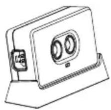
Left side:
- Use two M3-D screws to fix the TOF module to the left side of the extension platform, located above the chassis left armor.

- As shown below, connect the TOF module with the power connector module with a 14cm data cable.
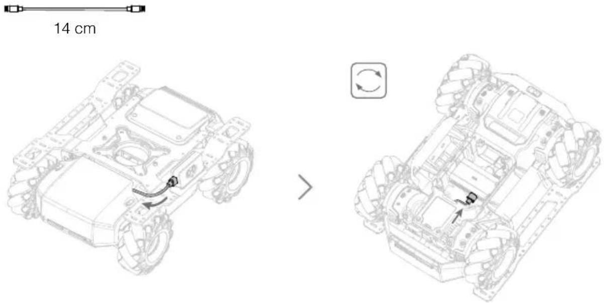
Right side:
- Use two M3-D screws to fix the TOF module to the right side of the extension platform, located above the chassis right armor.

- After removing the screws of the right armor, connect the TOF module with the right armor with a 12cm data cable.

- Arrange the data cable as shown below and remount the right armor.
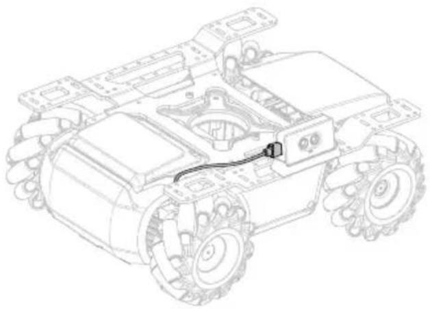
Front side:
- Use two M3-D screws to fix the TOF module to the straight connecting rod.

- Use two M3-C screws to fix the straight connecting rod to the front of the extension platform.

- As shown below, connect the TOF module with the power connector module with a 14cm data cable.

Serial Protocol Instruction
The infrared distance sensor supports CAN bus communication and plaintext serial protocol, enabling the sensor to be used on a third-party platform. Below shows the port configuration parameters:
| Property Parameter |
| Baud rate 115200 |
| Data bits 8 |
| Stop bit 1 |
| Parity bit / |
Communicate with the infrared distance sensor by sending a plaintext string via the serial. Below shows the control commands that the infrared distance sensor supports:
Description Control Command
Turn on the infrared distance sensor "ir_distance_sensor measure on"
Turn off the infrared distance sensor "ir_distance_sensor measure off"
After turning on the infrared distance sensor, the format of the returned data is shown below:
“ir distance: 100”, 100 (unit: mm) is a sample of measurement data that is produced by the sensor.
LED Indicator Description for Infrared Distance Sensor
The LED indicator is used to indicate the status of the infrared distance sensor. Details are as follows:
LED Indicator Infrared Distance Sensor Status
Solid cyan
Working normally
Blinks cyan rapidly

The infrared distance sensor is selected in the RoboMaster app
Using the Infrared Distance Sensor
The infrared distance sensor should not be interfered with or blocked and the lens should be clear and without stain when it is in use. It is not recommended to use the sensor in scenarios as shown below. Otherwise, the ranging precision may be reduced or the sensor may even be inoperable.
a. When using the sensor on mirrors or transparent objects.
b. When using the sensor on material of high absorbency such as matte black.
c. When using the sensor in rainy and foggy weather.
d. When using the sensor on a strong reflector such as a traffic sign or reflective strip.
e. When using the sensor in direct sunlight.
f. When using the sensor on an obstacle that is small or low.

- When mounted on the chassis extension platform, the TOF module is tilted upwards by 10 degrees and cannot detect the ground.
- When the TOF module is mounted on the gimbal, users can adjust the direction of detection and point towards the target object by controlling the gimbal. To avoid measuring unwanted data, it is not recommended to point the gimbal towards the ground or ceiling.
Sensor Adapter
Introduction
The RoboMaster EP is equipped with four sensor adapters, with IDs set to 1 by default. Each sensor adapter has two sensor ports and provides a power supply, making it convenient to connect and power third-party sensors that measure inputs such as temperature, pressure, and distance. Sensory data can even be used in Scratch, unlocking endless programming possibilities.

4
- CAN Bus Port
Connect with CAN bus cable.
- LED Indicator
Indicates the status of the sensor adapter.
- Addressing Button
Set the ID of the sensor adapter.
- Sensor Port
Supports the collection of switch and analog signals and has an input range of 0-3.3 V.
Mounting the Sensor Adapter
- Use eight M3-C screws to fix two sensor adapters to the specific positions on the rear of the extension platform as shown below.

- After removing the screws of the left armor and right armor, connect the respective sensor adapters with the armors using two 12cm data cables.
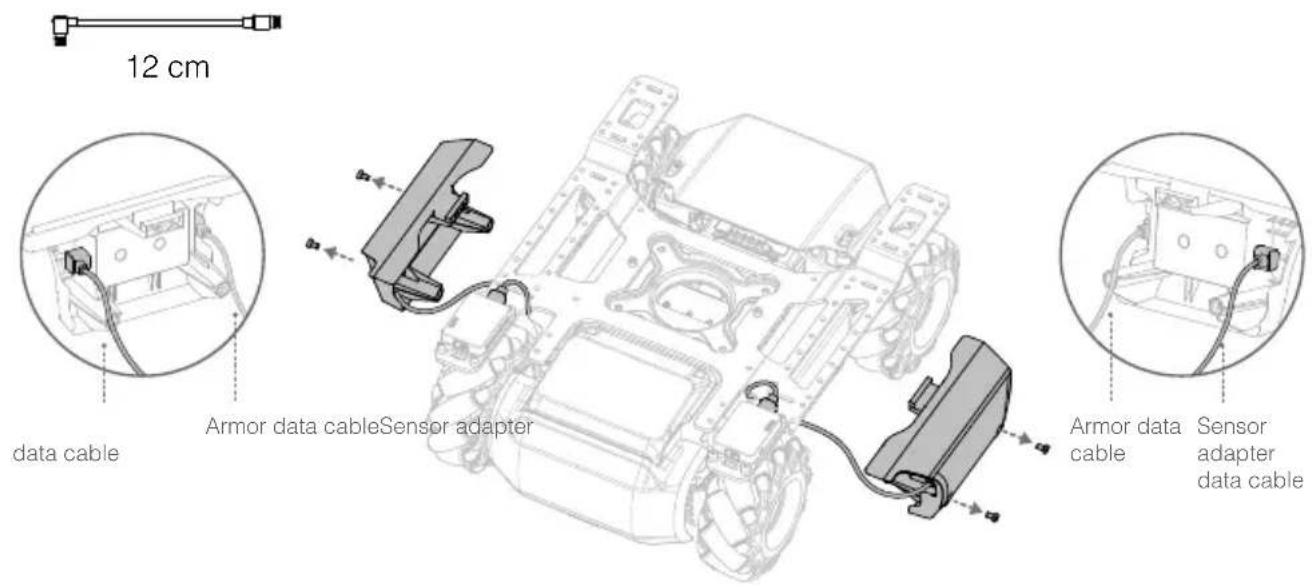
- Arrange the data cables as shown below and remount the armor.

- Use eight M3-C screws to fix two sensor adapters to the specific positions on the front side of the extension platform as shown below.

- As shown below, connect the sensor adapter with the power connector module using two 14cm data cables.
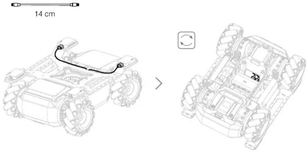
LED Indicator for Sensor Adapter
The LED indicator is used to indicate the status of the sensor adapter. Details are as follows:
| LED Indicator Sensor Adapter Status | ||
| Solid white | W — | Working normally |
| Blinks white rapidly | W ...... | The sensor adapter is under addressing or selected in the RoboMaster app |
Straight Connecting Rod
The straight connecting rod can be fixed to the chassis extension platform so that an infrared distance sensor or camera can be installed. Below shows the installation procedure for the camera.
- Use two M3-C screws to fix the camera to the specific position on the straight connecting rod as shown below.

- Use two M3-C screws to fix the straight connecting rod to the front of the chassis as shown below.

- Connect the camera with the intelligent controller using a camera extension cable.

Front Axle Extension Platform
The front axle extension platform can be fixed to the front of the chassis so that a gripper or sensor can be installed. Below shows the installation procedure for the gripper.
- Use four M3-C screws to fix the gripper to the specific position on the front axle extension platform as shown below.

- Use four M3-C screws to fix the front axle extension platform to the front of the chassis as shown below.

Extension Building Block
The RoboMaster EP is compatible with third-party building blocks. Below is an introduction on how to mount building rods to the RoboMaster EP.
As shown below, use four M3-B screws to fix the building rods to the chassis extension platform. More building blocks can then be added to the EP.

EP and Third-Party Platforms
The RoboMaster EP is compatible with third-party platforms. Third-party platforms are powered by the power connector module and communicate with the EP using the SDK protocol. For more information, visit robomaster-dev.rtfd.io.
There are two ways to connect the EP with third-party platforms:
a) UART Connection
The third-party platform Arduino™ connects with the power connector module and communicates with the EP via the UART port of the motion controller as shown below:
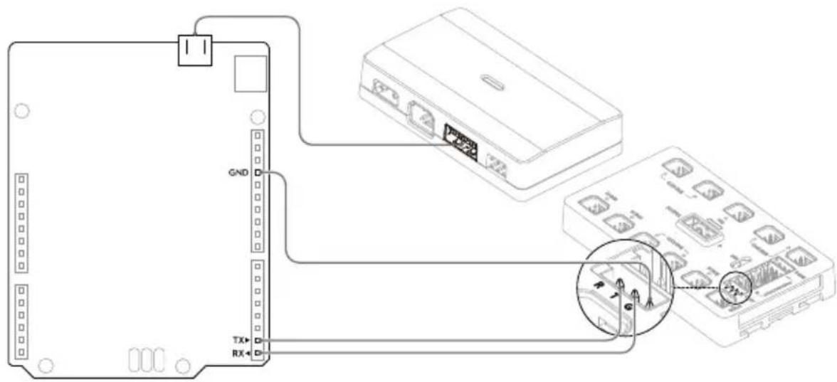
The third-party platform Micro:bit™ connects with the power connector module and communicates with the EP via the UART port of the motion controller as shown below:

b) USB Connection
The third-party platform Raspberry Pi™ connects with the power connector module and communicates with the EP via the USB port of the intelligent controller as shown below:

The third-party platform Jetson Nano™ connects with the power connector module and communicates with the EP via the USB port of the intelligent controller as shown below:


This product is not authorized, sponsored, or otherwise approved by the above brands, and the connection between this product and the above brands should be taken as a reference only.
Gamepad (Not Included)
Introduction
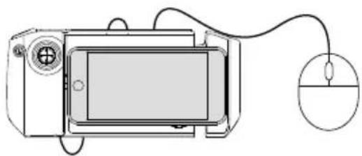
By connecting to a mobile device running the RoboMaster app, users can control the robot and perform multiple tasks with the gamepad and app. Additionally, a mouse can be connected to the gamepad for more precise control of the robot.
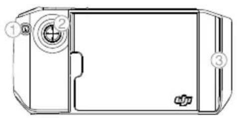
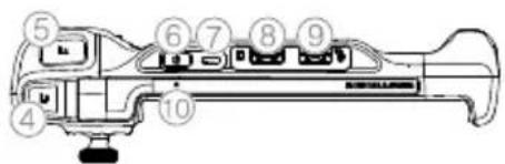

- Custom Skills Button
- Control Stick
- Mobile Device Clamp
- Cooldown Button
- Launch Button
- Power Button
- Charging Port (Micro USB)
- Mobile Device Port (USB)
- Mouse Port (USB)
- Status LED
- Gamepad Stand
- Mystery Bonus Button

Note that there are two USB ports available on the gamepad. The mobile device port cannot be used as the mouse port, and vice versa.
Charging the Gamepad
It is recommended to fully charge the gamepad before using for the first time.

It takes approximately two hours to fully charge a gamepad. The USB charger is not included in the package.
Firmware Update
The firmware of the gamepad can be updated using the RoboMaster app. When there is a firmware update available, the RoboMaster app will send a prompt after the gamepad is connected. Follow the prompts to update the firmware.

Internet
Make sure the mobile device is connected to the internet when downloading the firmware.
Status LED Description
The status LED indicates the working status and current battery level of the gamepad.
Status LED Description
Blinks green slowly: The gamepad is charging
Blinks red quickly: The gamepad's battery level is 0%
Solid red: The gamepad's battery level is between 1% to 29%
Solid yellow: The gamepad's battery level is between 30% to 69%
Solid green: The gamepad's battery level is between 70% to 100%
Solid blue: The gamepad is initializing
Specifications
Model GD0MA
Built-in Battery Type: 3.6 V, 2600 mAH, 1S1P
Working Hours*: Approx. 2 hours
USB Port: 500 mA / 5 V
Operation Temperature Range: -10° to 45° C (14° to 113° F)
Charging Temperature Range: 0° to 45° C (32° to 113° F)
Charging Hours*: Approx. 2 hours
* The working hours were tested using an Android device, and the charging hours were tested using a 10 W USB charger at a temperature of 25°C (77°F). Both the working hours and the charging hours were tested in a lab environment, and should be taken as a reference only.
Operating Your EP
Checking Before Use
Check the following each time you use the robot:
- Make sure the motion controller is properly installed, all cables are connected, and the screws on the chassis rear cover are tightened.
- Make sure the intelligent controller, blaster, camera, and speaker are connected.
- Make sure the microSD card is inserted.
- Make sure the intelligent battery is fully charged and properly inserted.
- For optimal Wi-Fi connection, set the intelligent controller antennas at 90°.
Powering on the Battery
Press and hold the power button for more than two seconds to power on or off.

Operating the Robot Using a Mobile Device
Connecting to the App
The robot must be connected to the RoboMaster app in order to use.
Selecting a Location
It is recommended to use the robot on flat surfaces such as wooden floors and carpets. Uneven surfaces such as sand or rocks may damage the wheels or motors.
Using Solo Mode
Enter Solo mode to see the page below.
Warrior Form
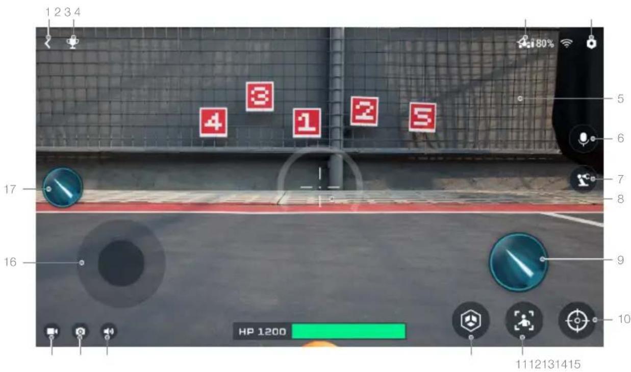
- Back button: Tap to return to the home page.
- Solo mode games button: Tap to enter Target Practice or Target Race.
- Connection status button: Tap to see how to connect the EP and the app.
- Settings button: Tap to enter the Settings page.
- Gimbal slider: Tap and slide on this area of the screen to control the rotation of the gimbal.
- Intercom button: Tap to record and play an audio.
- Robotic arm button: Tap to switch the FPV interface.
- Sight: Used to aim at targets.
- Launch button: Tap to launch gel beads or emit an infrared beam.
- Zoom button: Tap to zoom in or out 4x.
- Follow mode: Tap to enter Follow mode.
Note that the Follow mode will be affected in the following situations:
a. The person being followed is partly or completely obstructed. b. The person being followed suddenly changes their movement dramatically. c. The environment suddenly changes from light to dark, or vice versa. d. The color or pattern of the person being followed is similar to the environment.
- Custom skills button: Tap to perform preprogrammed custom skills.
- Mute button: Tap to mute or unmute the sound on the mobile device.
- Shutter button: Tap to capture a photo.
- Record button: Tap to record a video.
- Chassis control button: Tap to move the chassis.
- Launch button: Tap to launch gel beads or emit an infrared beam.
Engineer Form

- Back button: Tap to return to the home page.
- Solo mode games button: Tap to enter Target Practice or Target Race.
- Connection status button: Tap to see how to connect the EP and the app.
- Settings button: Tap to enter the Settings page.
- Robotic arm control slider: Tap to lift or lower the robotic arm.
- Intercom button: Tap to record and play an audio.
- Robotic arm button: Tap to switch the FPV interface.
- Gripper control slider: Tap to control the grip distance of gripper.
- Zoom button: Tap to zoom in or out 4x.
- Follow mode: Tap to enter Follow mode.
Note that the Follow mode will be affected in the following situations:
a. The person being followed is partly or completely obstructed. b. The person being followed suddenly changes their movement dramatically. c. The environment suddenly changes from light to dark, or vice versa. d. The color or pattern of the person being followed is similar to the environment.
- Custom skills button: Tap to perform preprogrammed custom skills.
- Sight: Used to aim at targets.
- Mute button: Tap to mute or unmute the sound on the mobile device.
- Shutter button: Tap to capture a photo.
- Record button: Tap to record a video.
- Chassis control button: Tap to move the chassis.
- Robotic arm control slider: Tap to fold or unfold the robotic arm.
Operating the Robot
The camera view is mainly used to control the chassis, gimbal, robotic arm, gripper, and blaster of the robot.
Controlling the Chassis
Tap the chassis control button to move the robot forward, backward, or sideward.
If the EP is assembled into a Warrior form, the launch button can be tapped at the same time to launch gel beads or emit infrared beams while moving the chassis.
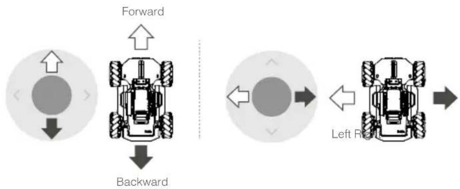
Controlling the Gimbal
If the EP is assembled into a Warrior form, tap on the right side of the screen to rotate the yaw and pitch of the gimbal. The launch button can be tapped at the same time to launch gel beads or emit infrared beams while rotating the gimbal.
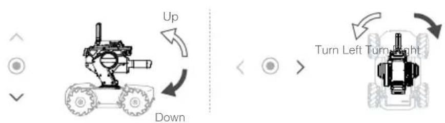

DO NOT aim the blaster at people or animals when launching the gel beads. DO NOT point the launch trajectory light at yours or other people's eyes.
Controlling the Robotic Arm
If the EP is assembled into an Engineer form, tap the robotic arm button to switch to the Engineer FPV interface. The robotic arm control sliders can be used to lift or lower and fold or unfold the robotic arm.
Controlling the Gripper
If the EP is assembled into an Engineer form, tap the robotic arm button to switch to the Engineer FPV interface. Use the gripper control slider on the bottom right to control the grip distance of the gripper.
Gameplay
Solo Mode
Introduction
In Solo mode, users can enter Follow mode and explore single-player Target Practice and Target Race. Users can enter the Solo mode games from the camera view. Users can also experience greater control with the robotic arm and gripper.
The intercom function is supported in the first person view. Audios can be recorded in real time and played via the EP. Recorded files in the RoboMaster app can also be played.
The app can only save 10 recorded files at a time and each recording can be no longer than 60 seconds.
Target Practice
In Target Practice, users hit the vision markers as fast as possible before the time expires. High scores can be compared with other users. Users can set the vision markers beforehand.
- Set up Vision Markers. Refer to the AI Modules section for more information about installing vision markers.

- Tap to enter Target Practice.


Tap in the upper right corner to read the game rules.
3. Start Target Practice.

Target Race
In Target Race, users race to vision markers and hit them as fast as possible before the time expires. High scores can be compared with other users. Users can set the vision markers beforehand. Target Race is available in Manual and Auto mode. In Manual mode, the user drives the robot manually. In Auto mode, the user creates a Line Recognition program to use in the race.
1. Set up Vision Markers.
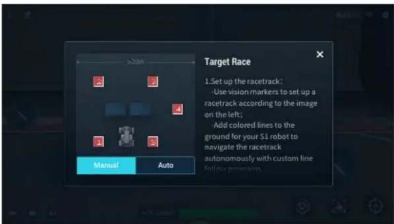
2. Tap to enter Target Race, then select the Firing Mode and the number of Vision Markers.
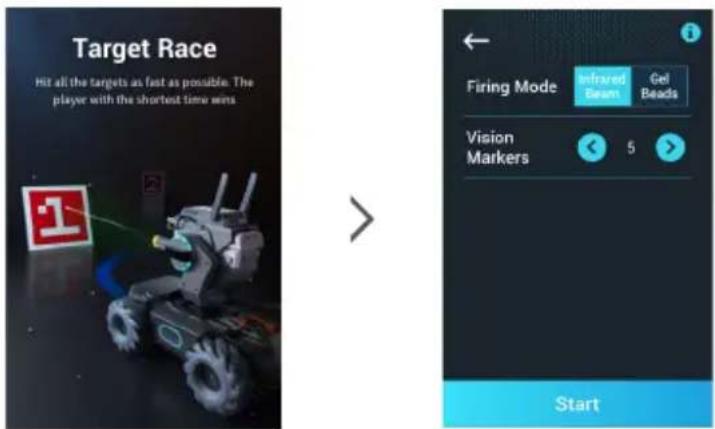

Tap on the upper right corner to read the game rules.
- Play Target Race.

Battle
Introduction
In Battle mode, users can experience a variety of multiplayer games, including Race, Free-For-All, and Conquest. Users can also experience greater control with the robotic arm and gripper. Refer to the Connect section for more information on how to enter Battle mode.
Race Mode
In Race mode, users arrange vision markers as checkpoints and scan them as fast as possible to win the game. The markers must be scanned in sequence to complete the race.

- Tap to read the game rules. Arrange vision markers as checkpoints according to the rules.
- Set the Laps, Checkpoints, and Speed.
- Tap to read the Mystery Bonus descriptions. Bonuses include Dizziness, Electromagnetic Interference, Extreme Speed, and Invincibility.
- Tap to start the game.
- Tap to enter FPV.
- All players in the game room.
- The host of the game room.

- All players are required to connect to the same game room through the same router. • To ensure fair play, all players are required to use the same firmware version.
Free-For-All Mode
In Free-For-All, users launch gel beads or emit infrared beams at opponent robots. If a robot is hit, the Hit Point Bar is reduced. If the Hit Point Bar of the robot is reduced to zero, the robot is defeated. Defeated robots can be revived by scanning 🤖 Users receive points by hitting or defeating opponent robots. At the end of the time limit, the user with the most points is the winner.

- Tap to read the game rules. Arrange vision markers as checkpoints according to the rules.
- Set the Firing Mode, Time, HP, and Speed.
- Tap to read the Mystery Bonus descriptions. Bonuses include Dizziness, Electromagnetic Interference, Extreme Speed, and Invincibility.
- Tap to start the game.
- Tap to enter FPV.
- All players in the game room.
- The host of the game room.

- All players are required to connect to the same game room through the same router. • To ensure fair play, all players are required to use the same firmware version.
Conquest Mode
Conquest mode is a game where users are divided into red and blue teams that compete to occupy the most bases and score the most points. Users launch gel beads and emit laser beams at opposition robot to help defeat the other team and win the game.
If a robot is hit, the Hit Point Bar is reduced. If the Hit Point Bar of the robot is reduced to zero, the robot is defeated. A defeated robot can be revived by scanning an active revive point or base occupied by their team. The blue team's revive point is marked with [1]+[1] and the red team [2]+[1] .
Points are gained by hitting or defeating opponent robot or occupying bases.

- The host of the game room.
- All players in the game room.
- Tap to read the game rules. Arrange vision markers as checkpoints according to the rules.
- Set the Firing Mode, Time, HP, and Speed.
- Tap to read the Mystery Bonus descriptions. Bonuses include Dizziness, Electromagnetic Interference, Extreme Speed, and Invincibility.
- Tap to set the active state of revive point and base.
- Tap to start the game.
- Tap to enter FPV.
The parameters of the firing mode, time, and active state of revive points and bases are set by the referee by default. Any player can serve as referee. If no player chooses to be referee, the parameters are set by the host of the game room.

- All players are required to connect to the same game room through the same router. • To ensure fair play, all players are required to use the same firmware version.
Mystery Bonus
In Battle mode, scan to receive a Mystery Bonus in the game. The bonuses include:
Dizziness: Target opponent robot, trigger the skill, and cause the robot to spin uncontrollably for 1.5 seconds.
Electromagnetic Interference: Trigger the skill and cause all opponent robots within a 3-meter radius to experience screen interference for 2.5 seconds.
Extreme Speed: Triggering this skill allows your robot to drive at a higher speed for 3 seconds.
Invincibility: Triggering this skill gives your robot a virtual shield that prevents it from being hit for 3 seconds.
Operating the Robot Using a Gamepad
Introduction
Users can connect the Gamepad to a mobile device to control the robot in the following ways:
- Using the gamepad connected to a mobile device.
- Using the gamepad connected to a mobile device with a mouse attached.
- Using the gamepad connected to a mobile device with a mouse and keyboard attached.
Connecting the Gamepad
- Connect the mobile device to the mobile device port on the gamepad using a micro USB cable (not included).
- Adjust the mobile device clamp to secure it to the gamepad. Make sure the mobile device is connected with the cable facing toward the control stick as shown in the figure below.
- Press the power button to power on the gamepad. Press and hold the power button to power off the gamepad.
Gamepad Basic Operation
- When the gamepad is connected to a mobile device, the control stick on the gamepad is used to move the robot forward, backward, and sideward. The app cannot be used to control the chassis.
- The buttons on the gamepad can be used to perform actions on the EP. Users can also continue to use the app to perform these actions.
Using the Gamepad
The control stick on the gamepad is used to control the chassis. The app is used to control the gimbal and blaster. When the gamepad is connected, it is not possible to move the chassis using the app.

| Control Stick Movement | Robot Movement | Control Stick Movement | Robot Movement |
 | Forward Backward Backward |  |  |
The control stick on the gamepad is used to move the robot forward, backward, and sideward.
Using the Gamepad and Mouse
After the gamepad is connected to a mobile device, a computer mouse can also be connected to the gamepad. The control stick on the gamepad is used to control the chassis. The mouse actions are listed below. The app can still be used to control the gimbal and gamepad, but the mouse is the primary controller.
| Mouse Action Robot Action |
| Left click Launches gel beads |
| Right click Zooms in |
| Scroll mouse wheel No action |
| Move mouse Adjusts gimbal angle |
Using the Gamepad, Mouse, and Keyboard
A wireless mouse and keyboard are required. After the gamepad is connected to a mobile device, attach the wireless connector of the mouse and keyboard to the gamepad. The control stick on the gamepad and the keyboard are used to control the chassis. The mouse actions are listed below. The app can still be used to control the gimbal and blaster, but the mouse is the primary controller.
The A, W, S, and D keys are used to control the chassis. The actions that can be performed with the mouse are listed below.

| Keyboard Keys Robot Action | |
| W Forward | |
| A Left | |
| S Backward | |
| D Right | |
| Shift / Space Accelerate | |
| Mouse Action Robot Action | |
| Left click Launches gel beads | |
| Right click Zooms in | |
| Scroll mouse wheel No action | |
| Move mouse Adjusts gimbal angle |
Most Logitech and Rapoo keyboard and mouse devices are supported. It is recommended to use the following models:
Rapoo: 8200P, 9300P, 1800, 8100M
Logitech: M310t, MK850
Using a Computer and RoboMaster
Install the Windows or Mac version of the RoboMaster app to a computer and control the EP directly via a mouse and keyboard.
Installing the Windows or Mac Version of RoboMaster
- Users can download the RoboMaster app for Windows or Mac from the official DJI website on a computer to control the robot with a keyboard and mouse.
Windows: https://www.dji.com/robomaster_app
Mac: https://www.dji.com/robomaster_app
- Run the installation and follow the prompts to complete the RoboMaster app installation.
- Run the RoboMaster app to enter the homepage. The Windows or Mac version of the RoboMaster app is similar to the version for iOS and Android.
Using a Mouse and Keyboard to Control the Robot
When using RoboMaster for Windows or Mac, the robot is controlled with a mouse and keyboard. The corresponding actions are shown below.

In the Engineer form, press and hold the space bar on the keyboard and use the A, W, S, and D keys to control the robotic arm and gripper.
Lab
The RoboMaster app Lab offers hundreds of programming blocks that allow you to access features such as PID control. The RoboMaster EP Programming Manual provides instructions and examples to help users quickly learn programming techniques for controlling the robot.
Users can study project-based courses in Road to Mastery to enhance their understanding of programming languages, from robotics applications to AI technology, with different projects for both beginners and experts.
Scratch Programming
In Lab, go to the Scratch page and then DIY Programming to write programs.
New Scratch programming blocks have been added to the Lab section of the RoboMaster app, which are designed to help users obtain and utilize sensory data. With these blocks, users can quickly access and control the sensor adapter, robotic arm, gripper, infrared launcher, infrared distance sensor, and third-party open-source hardware.
In the Scratch page, users can write their own Python programs, which can be set as Autonomous Programs or Custom Skills and run on the robot.
Refer to the RoboMaster EP Programming Manual for more information.

- Scratch page: Tap to view Scratch programs.
- Python page: Tap to view Python programs.
- Import DSP file: This function is available on Android, Windows, and Mac devices. DSP files can be imported to iOS devices by using AirDrop.
- Cloud space: Tap to view programs in the cloud space.
- Program name: Displays the name of the program.
- If the program is set as a general program, the program type is not displayed. The program type is only displayed if it is set as a custom skill or autonomous program.
- Program settings: Tap to select the program type, set the program as a custom skill, set the program as an autonomous program, backup on the cloud space, share with other users, and rename or delete the program.
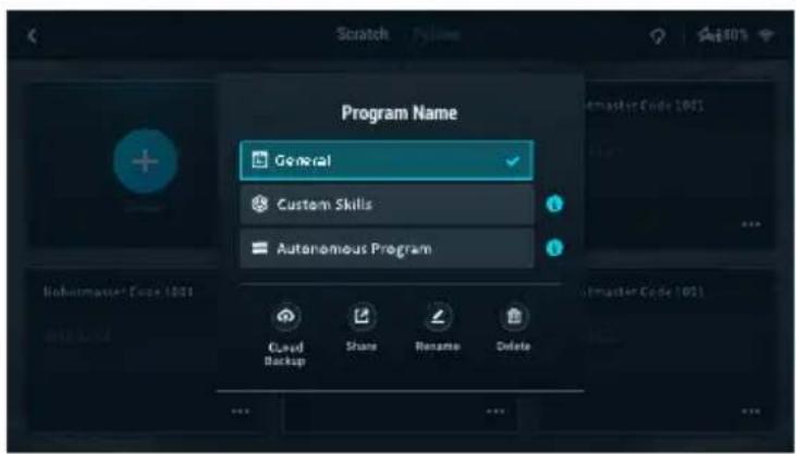
- Tap to create a new program.
A. Programming modules button: Tap the corresponding icon to program System, LED Effects, Chassis, Gimbal, Blaster, Smart, Armor, Mobile Device, Media, Commands, Operators, and Data Objects.
B. Programming window button: Drag programming blocks into the window to create a program.
C. Display button: Tap to turn the FPV on or off.
D. Switch button: Tap to switch to view the programming block as Python code.
E. Run button: Tap to run the program.
F. FPV window: See the current FPV.
G. Status information: View the current status information of the robot.
H. FPV button: Tap to enter the FPV in full screen

AI Modules
There are six AI modules that can be programmed by entering Lab then DIY Programming then Scratch. Refer to the Smart section of the RoboMaster EP Programming Manual for more programming examples.
Note that the AI module will be affected in the following situations:
a. The object is partly or completely obstructed. b. The environment is dark (less than 300 lux) or bright (greater than 10,000 lux). c. The environment suddenly changes from light to dark, or vice versa. d. The color or pattern of the object is similar to the environment.
Person Recognition
The robot is able to identify and track any individual selected in the FOV of the robot.
Line Recognition
When in Target Race, the user can program the robot to automatically follow a line on the ground. Line Recognition supports red, green, and blue lines. The robot cannot recognize lines of other colors.
Gesture Recognition
The user can program the robot to perform unique responses when identifying physical gestures.
Clapping Recognition
The user can program the robot to perform unique actions in response to clapping. Only claps within an effective distance of 2 meters can be identified. Identified clapping sequences include two consecutive claps and three consecutive claps.
Robot Recognition
The user can program the robot to perform unique responses when other robots are recognized.
Vision Marker Recognition
The user can program the robot to perform unique responses when identifying vision markers, which include numbers, letters, and special characters. Vision markers must be within an effective distance of three meters and only official vision markers can be identified. Refer to the instructions on the packaging of the vision markers for more information.
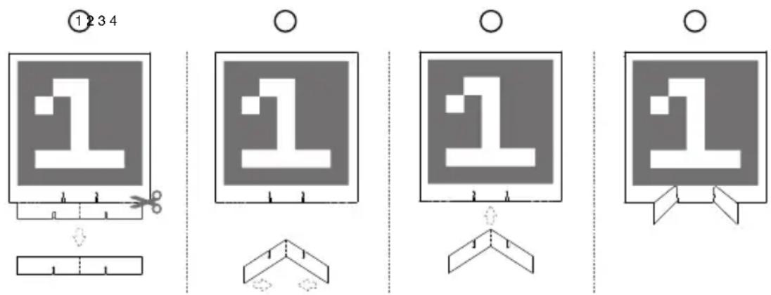

DO NOT block the color areas like red and blue. Otherwise, recognition will be affected.
If you need to use more vision markers, tap 📄 the app to enter the guide page. Select the vision markers you wish to download and print.

Vision Marker Recognition only supports red and blue markers. The robot cannot recognize vision markers of other colors.
Autonomous Program
A program can be set as an autonomous program and can be run independently on the robot.
- If the robot is not connected to the app, the program can be launched by pressing the autonomous program button on the intelligent controller. Press the button again to stop the program.

- If the robot is connected to the app, the autonomous program can only be launched in the following locations:
(1) App homepage (2) Solo mode FPV (3) Lab
Custom Skills
A program can be set as a custom skill, which can be used in the FPV in both Solo and Battle mode. Tap 📂 in the FPV to use a custom skill.
Python Programming
In Lab, go to the Python page then DIY Programming to write programs.
In the Python page, users can write their own Python program, which can be set as an Autonomous Program or a Custom Skill and run on the robot.
Users can also convert Scratch programs into Python code and use the source code display to help get started with programming with Python. Refer to the RoboMaster EP Programming Manual for more information.
With the addition of a multi-machine communication port, Python programming allows multiple EPs to communicate and interact with each other in real time. The RoboMaster EP supports customizable UI. Users can code virtual widgets with Python to design their own user interfaces and more.
Appendix
Specifications
| RoboMaster EP | |
| Dimensions (L×W×H) | Warrior form: 320×240×270 mmEngineer form: 410×240×330 mm |
| Weight | Warrior form: Approx. 3.4 kgEngineer form: Approx. 3.3 kg |
| Chassis Speed Range | 0-3.5 m/s (forward)0-2.5 m/s (backward)0-2.8 m/s (sideward) |
| Max Chassis Rotational Speed 600°/s | |
| M3508I Brushless Motor | |
| Max Rotational Speed 1000 rpm | |
| Max Torque 0.25 N·m | |
| Max Output Power 19 W | |
| Operating Temperature Range -10 to 40 °C (14 to 104 °F) | |
| Driver Field-oriented control (FOC) | |
| Control Method Closed-loop speed control | |
| Protection | Overvoltage protectionOverheating protectionSoft-starterShort-circuit protectionChip and sensor anomaly detection |
| Gimbal | |
| Controllable Range -20° to +35° (pitch); ±250° (yaw) | |
| Mechanical Range -24° to +41° (pitch); ±270° (yaw) | |
| Max Rotational Speed 540°/s | |
| Vibration Control Precision(on a flat surface, blaster idle) | ±0.02° |
| Blaster | |
| Controllable Launching Frequency 1-8/s | |
| Max Launching Frequency 10/s | |
| Initial Launching Speed Approx. 26 m/s | |
| Average Load Approx. 430 gel beads (soaked) | |
| Intelligent Controller | |
| Latency[1] | Connection via Wi-Fi: 80-100 msConnection via Router: 100-120 ms (unobstructed, free of interference) |
| Live View Quality 720p/30fps | |
| Max Live View Bitrate 6 Mbps | |
| Operating Frequency[2] | 2.4 GHz, 5.1 GHz, 5.8 GHz |
| Transmission Power (EIRP) | 2.400-2.4835 GHzFCC: ≤30 dBmSRRC: ≤20 dBmCE: ≤19 dBmMIC: ≤20 dBm5.150-5.250 GHzFCC: ≤30 dBmSRRC: ≤23 dBmCE: ≤20 dBmMIC: ≤23 dBm5.725-5.850 GHzFCC: ≤30 dBmSRRC: ≤30 dBmCE: ≤14 dBm |
| Operating Mode Connection via Wi-Fi, Connection via Router | |
| Max Transmission Distance[3] | Connection via Wi-Fi:FCC, 2.4 GHz 140 m, 5.8 GHz 90 mCE, 2.4 GHz 130 m, 5.8 GHz 70 mSRRC, 2.4 GHz 130 m, 5.8 GHz 130 mMIC, 2.4 GHz 130 mConnection via Router:FCC, 2.4 GHz 190 m, 5.8 GHz 300 mCE, 2.4 GHz 180 m, 5.1 GHz 70 mSRRC, 2.4 GHz 180 m, 5.8 GHz 300mMIC, 2.4 GHz 180 m |
| Transmission Standard IEEE802.11a/b/g/n | |
| Camera | |
| Sensor CMOS 1/4"; Effective pixels: 5MP | |
| FOV 120° | |
| Max Still Photo Resolution 2560×1440 pixels | |
| Max Video Resolution | FHD: 1080p/30fpsHD: 720p/30fps |
| Max Video Bitrate 16 Mbps | |
| Photo Format JPEG | |
| Video Format MP4 | |
| Supported SD Cards | Supports microSD cards with a capacity of up to 64 GB |
| Operating Temperature Range -10 to 40 °C (14 to 104 °F) | |
| Narrow Infrared Units | |
| Effective Range[4] | 6 m (in indoor lighting conditions) |
| Effective Area | Varies from 40° to 10° (effective area decreases as the distance from the target increases) |
| Wide Infrared Units | |
| Effective\ Range[4] | 3 m (in indoor lighting conditions) |
| Effective Width 360° (in indoor lighting conditions) | |
| Hit Detector | |
| Detection Requirements | For the hit detector to be activated, the following conditions must be met: Gel bead diameter ≥ 6 mm, launching speed ≥20 m/s, and the angle between the hit direction and hit detector plane is no less than 45°. |
| Maximum Detection Frequency 15 Hz | |
| Intelligent Battery | |
| Capacity 2400 mAh | |
| Maximum Charging Voltage 12.6 V | |
| Nominal Charging Voltage 10.8 V | |
| Battery Type LiPo 3S | |
| Energy 25.92 Wh | |
| Battery Life (in use) | 35 mins (measured at a constant speed of 2.0 m/s on a flat surface) |
| Battery Life (on standby) Approx. 100 mins | [5] |
| Weight 169 g | |
| Operating Temperature Range -10 to 40 °C (14 to 104 °F) | |
| Charging Temperature Range 5 to 40 °C (41 to 104 °F) | |
| Maximum Charging Power 29 W | |
| Charger | |
| Input 100-240 V, 50-60 Hz, 1 A | |
| Output Port: 12.6 V=0.8 A or 12.6 V=2.2 A | |
| Voltage 12.6 V | |
| Rated Voltage 28 W | |
| Gel Bead | |
| Diameter | 5.9- 6.8 mm[6] |
| Weight 0.12-0.17 g | [6] |
| App | |
| iOS | iOS 10.0.2 or later |
| Android | Android 5.0 or later |
| Others | |
| Recommended Routers | TP-Link TL-WDR8600; TP-Link TL-WDR5640 (China)TP-Link Archer C7; NETGEAR X6S (International) |
| Recommended outdoor power supply solution for routers | Portable laptop charger (with the same input power of the router) |
| Robotic Arm | |
| Movement Range 0-0.22 m (horizontal); 0-0.15 m (vertical) | |
| Axis Number 2 | |
| Gripper | |
| Grip Distance Approx. 10 cm | |
| Servo | |
| Weight Approx. 70 g | |
| Main Body Dimensions (L×W×H) 44.2×22.6×28.6 mm | |
| Transmission Ratio 512 | |
| Rated Torque 1.2 N*m | |
| Rated Rotational Speed 40±2 rpm | |
| Operating Mode Angle mode, rate mode | |
| Infrared Distance Sensor | |
| Detection Range 0.1-10 m | |
| Detection FOV 20° | |
| Measurement Accuracy 5% | [7] |
| Power Connector Module | |
| Communication Port CAN bus × 5 | |
| Input TX30 port: 12 V | |
| Output | USB Type-C port: 5 V, 2 APin header port: 5 V, 4 ATX30 port: 12 V, 5 A |
| Sensor Adapter | |
| Port Type IO input, AD output | |
| Port Number 2 | |
[1] Measured in an interference-free and unobstructed environment with a distance of approximately one meter between the mobile device, the router, and the EP. The iOS device used was an iPhone X. The results of testing with different Android device may be different. [2] Outdoor use of the 5.1 GHz and 5.8 GHz frequency bands is prohibited in some areas. Follow all local laws and regulations in your country or region. [3] Measured in an interference-free and unobstructed environment. For Connection via Wi-Fi, the mobile device used for testing was a sixth-generation iPad (released in 2018). For Connection via Router, several router models were used for testing. FCC: TP-Link Archer C9; SRRC: TP-Link WDR8600; CE: TP-Link Archer C7; MIC: WSR-1160DHP3. [4] Use of the infrared units will be affected in outdoor or infrared-intensive environment. [5] Tested in a lab environment using a new intelligent battery, and should be taken as a reference only. [6] The gel beads will swell to a usable size after being soaked in water for four hours. [7] Applied to an object surface whose reflectivity ranges from 10-90%.
Firmware Update
Check the robot firmware version in Settings, then System, and then Firmware Update. If there is a new firmware version, use the RoboMaster app to update the firmware of the robot.
- Make sure that all parts are connected, power on the robot, and check to make sure the battery level is above 50%.
- Tap App, then System, and then Firmware Update. Follow the onscreen instructions to update the firmware. Make sure the mobile device is connected to the internet when downloading the firmware.
- The robot tracks the progress of the update using audio prompts. Wait until the update is complete.


- The battery firmware is included in the robot firmware. Make sure to update the firmware of all batteries if you have several.
- Only start a firmware update if the battery level is above 50%.
- Note that while updating the firmware, the status indicators may blink abnormally (the gimbal may go limp if the EP is assembled into a Warrior form), and the robot may reboot.
- The robot and app may disconnect after updating. If this occurs, reconnect them.
- If you receive a prompt that newer firmware version is out of date, update and try again.
- When in Battle mode, make sure that all the robots are using the same firmware version.
Calibrating the Robot
If any of the following scenarios occur, recalibrate the robot in the RoboMaster app:
Warrior Form
a. The pitch angle is not horizontal after performing the gimbal self-test. b. The gimbal attitude cannot be controlled precisely. c. The pitch cannot rotate horizontally when the yaw is controlled separately. d. The gimbal drifts when there is no operation or when the operation is stopped. e. The robot moves involuntarily while rotating. f. The chassis is uncontrollable and the gimbal goes limp when warning prompts appear in the app. g. The motion controller has been installed or reinstalled.
Engineer Form
a. The robot moves involuntarily while rotating. b. The chassis cannot be controlled when warning prompts appear in the app. c. The motion controller has been installed or reinstalled.
The specific calibration steps are as below:
- Open the RoboMaster app, tap on Settings, then System, and select Calibration.
- Follow the steps in the app to calibrate.

Setting the PWM Ports
PWM (pulse width modulation) controls the duration of a high level of output during a certain period, and is broadly used to control LEDs, navigation gears, and more. The PWM port has a default duty cycle of 7.5% and a fundamental frequency of 50 Hz.
For LEDs, the PWM output rate ranges from 0% to 100%, with 0% corresponding to an LED's lowest brightness and 100% to its highest brightness. For navigation gears, the PWM output rate ranges from 2.5% to 12.5%.
You can set the navigation gear PWM output percentage based on the rotation angles you wish to control.
Pulse Width Servo Angle

Each time the custom program or Python program finishes running, the PWM port output signal will be set to its default setting, which is 50 Hz and the duty cycle is 7.5%.
Using the S-Bus Port
A remote controller that supports the S-Bus protocol can be used to control the robot by connecting to the S-Bus port of the motion controller. Users must prepare their own receiver and remote controller. It is recommended to use a Futaba R6303SB receiver.
Connection
Connect the S-Bus port of the motion controller to the S-Bus port of the receiver by using the 3-pin servo cable.
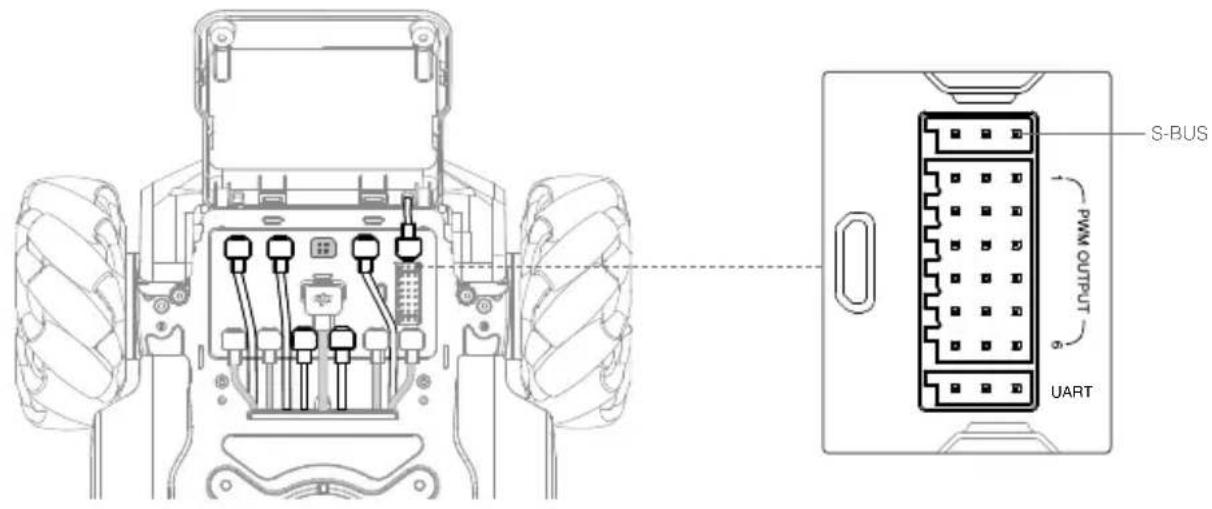
Usage
Make sure the remote controller has been linked with the receiver before use. Refer to the manual documents of the receiver for more information on linking methods.
The correspondence of control channels of the S-Bus port of the motion controller are shown below. Refer to the manual documents of the remote controller to complete the channel mapping between the receiver and remote controller.
| S-Bus Port Control Channels | Chassis Lead Mode | Free Mode | Recommended Remote Controller Channel | |||
| Remote Controller Channel | Offset Status | |||||
| Channel 1 | Move the chassis sideward | Move the chassis sideward | Control Stick Channel  |  | ||
| Channel 2 | Move the chassis forward and backward | Move the chassis forward and backward |  | |||
| Channel 3 | Control the pitch of the gimbal | / |  | |||
| Channel 4 | Control the yaw of the gimbal | Control the yaw of the chassis |  |  | ||
| Channel 5 | Control the movement speed of the chassis and there are three optional speeds:FastMediumSlow | 3-Position Switch Channel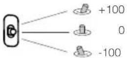 | Fast | |||
| Medium | ||||||
| Slow | ||||||
| Channel 6 | Switch the chassis mode and there are two optional modes:Chassis Lead modeFree mode | 2-Position Switch Channel | Chassis Lead mode | |||
| Free mode | ||||||
| Channel 7 | Control the release of the chassis and there are two statuses:Chassis is set when it produces output torqueChassis is released when it not producing output torque | 2-Position Switch Channel | Set | |||
| Release | ||||||
Programming Customizable UI
The customizable UI system expands the input and output modes of a program. Users can create UI widgets that are used to represent the input and output processing information of a program.
To code a Python program, call the related interfaces to generate a UI widget and bind the UI widget with an event callback. After coding and debugging in the Lab section of the RoboMaster app, users can save a program as a customizable skill and use it in Solo or Battle mode. For more information, visit www.dji.com/robomaster-ep/downloads or robomaster-dev.rtfd.io.
DJI Support
https://www.dji.com/support
This content is subject to change.
Download the latest version from
https://www.dji.com/robomaster-ep/downloads
If you have any questions about this document, please contact DJI by sending a message to DocSupport@dji.com.
Copyright © 2020 DJI All Rights Reserved.
- SEARCHING FOR KEYWORDS
- NAVIGATING TO A TOPIC
- PRINTING THIS DOCUMENT
- USING THIS USER MANUAL
- LEGENDS
- BEFORE USE
- WATCHING THE VIDEO TUTORIALS
- REFERRING TO THE ROBOMASTER EP PROGRAMMING MANUAL
- USING AN SDK
- CONTENTS
- PRODUCT PROFILE
- MODULES AND FUNCTIONS
- OPERATING YOUR EP
- GAMEPLAY
- APPENDIX
- INTRODUCTION
- EP DIAGRAM
- ENGINEER FORM
- OVERVIEW
- PREPARING
- ASSEMBLING THE ROBOT
- POWERING ON THE ROBOT
- DOWNLOADING THE ROBOMASTER APP
- CONNECTING THE ROBOT TO THE ROBOMASTER APP
- INITIALIZING THE ROBOT WITH THE APP
- ACTIVATING THE ROBOT
- MOTOR ADDRESSING
- ARMOR ADDRESSING
- ROBOTIC ARM INSTALLATION
- GRIPPER INSTALLATION
- SERVO INSTALLATION
- INFRARED DISTANCE SENSOR INSTALLATION
- SENSOR ADAPTER INSTALLATION
- USING THE ROBOMASTER APP
- ROBOMASTER APP MAIN PAGE
- ACCOUNT
- MEDIA LIBRARY
- GUIDE
- ANNOUNCEMENTS
- CONNECT
- CONNECTION VIA WI-FI
- RESETTING THE PASSWORD
- ROBOT MODEL SELECTION
- SETTINGS
- ROBOT
- EXTENSION MODULE
- DISPLAY
- CONTROL
- SYSTEM
- SOLO
- BATTLE
- LAB
- OMNIDIRECTIONAL CHASSIS
- MOTION CONTROLLER
- CAN BUS PORT
- POWER PORT
- M BUS PORT
- MICRO USB PORT
- UART PORT
- PWM OUTPUT PORT
- S-BUS PORT
- M0 PORT
- LED INDICATOR
- MECANUM WHEEL
- MOTORS AND ESCS
- ARMOR MODULES
- INTELLIGENT CONTROLLER
- MICROSD SLOT
- CAMERA PORT
- SPEAKER PORT
- AUTONOMOUS PROGRAM BUTTON
- ANTENNAS
- SECONDARY CAMERA PORT
- CONNECT MODE SWITCH
- CONNECT BUTTON
- CAMERA
- SPEAKER
- INTELLIGENT BATTERY
- INTELLIGENT BATTERY FUNCTIONS
- CHARGING THE INTELLIGENT BATTERY
- MOUNTING THE INTELLIGENT BATTERY
- USING THE INTELLIGENT BATTERY
- CHECKING THE BATTERY LEVEL
- POWERING ON/OFF
- LOW-TEMPERATURE NOTICE
- ROBOT LED INDICATOR DESCRIPTION
- LED INDICATOR DESCRIPTION
- GIMBAL
- YAW MOTOR
- PITCH MOTOR
- GIMBAL ARMOR
- WIDE INFRARED UNIT
- GIMBAL ARM SHAFT
- CAN BUS EXTENSION PORT
- USING THE GIMBAL
- BLASTER
- PREPARING THE GEL BEADS
- LOADING THE GEL BEADS
- INSTALLING/REMOVING THE GEL BEAD CONTAINER
- SERVO
- SERVO PWM PORT
- LED INDICATOR DESCRIPTION FOR SERVO
- ROBOTIC ARM AND GRIPPER
- USE INSTRUCTIONS
- GRIPPER PWM PORT
- POWER CONNECTOR MODULE
- MOUNTING THE POWER CONNECTOR MODULE
- LED INDICATOR DESCRIPTION FOR POWER CONNECTOR MODULE
- INFRARED DISTANCE SENSOR (TOF)
- SERIAL PORT
- MOUNTING THE INFRARED DISTANCE SENSOR
- LEFT SIDE
- RIGHT SIDE
- FRONT SIDE
- SERIAL PROTOCOL INSTRUCTION
- LED INDICATOR DESCRIPTION FOR INFRARED DISTANCE SENSOR
- USING THE INFRARED DISTANCE SENSOR
- SENSOR ADAPTER
- MOUNTING THE SENSOR ADAPTER
- LED INDICATOR FOR SENSOR ADAPTER
- STRAIGHT CONNECTING ROD
- FRONT AXLE EXTENSION PLATFORM
- EXTENSION BUILDING BLOCK
- EP AND THIRD-PARTY PLATFORMS
- USB CONNECTION
- GAMEPAD (NOT INCLUDED)
- CHARGING THE GAMEPAD
- FIRMWARE UPDATE
- STATUS LED DESCRIPTION
- SPECIFICATIONS
- MODEL GD0MA
- CHECKING BEFORE USE
- POWERING ON THE BATTERY
- OPERATING THE ROBOT USING A MOBILE DEVICE
- CONNECTING TO THE APP
- SELECTING A LOCATION
- USING SOLO MODE
- WARRIOR FORM
- OPERATING THE ROBOT
- CONTROLLING THE CHASSIS
- CONTROLLING THE GIMBAL
- CONTROLLING THE ROBOTIC ARM
- CONTROLLING THE GRIPPER
- SOLO MODE
- TARGET PRACTICE
- START TARGET PRACTICE
- TARGET RACE
- SET UP VISION MARKERS
- TAP TO ENTER TARGET RACE, THEN SELECT THE FIRING MODE AND THE NUMBER OF VISION MARKERS
- RACE MODE
- FREE-FOR-ALL MODE
- CONQUEST MODE
- MYSTERY BONUS
- OPERATING THE ROBOT USING A GAMEPAD
- CONNECTING THE GAMEPAD
- GAMEPAD BASIC OPERATION
- USING THE GAMEPAD
- USING THE GAMEPAD AND MOUSE
- USING THE GAMEPAD, MOUSE, AND KEYBOARD
- USING A COMPUTER AND ROBOMASTER
- INSTALLING THE WINDOWS OR MAC VERSION OF ROBOMASTER
- USING A MOUSE AND KEYBOARD TO CONTROL THE ROBOT
- SCRATCH PROGRAMMING
- AI MODULES
- PERSON RECOGNITION
- LINE RECOGNITION
- GESTURE RECOGNITION
- CLAPPING RECOGNITION
- ROBOT RECOGNITION
- VISION MARKER RECOGNITION
- AUTONOMOUS PROGRAM
- CUSTOM SKILLS
- PYTHON PROGRAMMING
- CALIBRATING THE ROBOT
- SETTING THE PWM PORTS
- USING THE S-BUS PORT
- CONNECTION
- USAGE
- PROGRAMMING CUSTOMIZABLE UI
Brand : DJI
Model : RoboMaster EP
Category : Educational robot