
LMD-DM20 - Monitor SONY - Free user manual and instructions
Find the device manual for free LMD-DM20 SONY in PDF.


| Product Type | Professional LCD Monitor |
| Screen Size | 20 inches (diagonal) |
| Resolution | 1920 x 1080 (Full HD) |
| Aspect Ratio | 16:9 |
| Brightness | 300 cd/m² (typical) |
| Contrast Ratio | 1000:1 |
| Viewing Angle | 178° horizontal / 178° vertical |
| Video Inputs | 3G/HD/SD-SDI (x2), HDMI, Composite |
| Video Outputs | 3G/HD/SD-SDI (x1), Composite |
| Audio | Built-in mono speaker, headphone jack |
| Power Consumption | Approx. 60 W |
| Power Requirements | AC 100-240 V, 50/60 Hz |
| Dimensions (W x H x D) | 476 x 366 x 97 mm (without stand) |
| Weight | Approx. 6.5 kg (without stand) |
| Mounting | VESA 100 x 100 mm |
| Operating Temperature | 0°C to 40°C |
| Key Features | Waveform monitor, vectorscope, time code display, focus assist, marker display |
| Cleaning | Use a soft dry cloth; avoid solvents |
| Safety | Indoor use only; do not expose to moisture |
| Repairability | Refer to qualified service personnel; use specified parts |
| General Information | Manufactured by Sony; model LMD-DM20 |
Frequently Asked Questions - LMD-DM20 SONY
User questions about LMD-DM20 SONY
0 question about this device. Answer the ones you know or ask your own.
Ask a new question about this device
Download the instructions for your Monitor in PDF format for free! Find your manual LMD-DM20 - SONY and take your electronic device back in hand. On this page are published all the documents necessary for the use of your device. LMD-DM20 by SONY.
USER MANUAL LMD-DM20 SONY
Instructions for Use
Before operating the unit, please read this manual thoroughly and retain it for future reference.
LMD-DM50
LMD-DM30
LMD-DM20
CE
Owner's Record
The model and serial numbers are located at the rear. Record these numbers in the spaces provided below. Refer to these numbers whenever you call upon your Sony dealer regarding this product.
Model No. ____
Serial No. ____
WARNING
To reduce the risk of fire or electric shock, do not expose this apparatus to rain or moisture.
To avoid electrical shock, do not open the cabinet. Refer servicing to qualified personnel only.
No modification of this apparatus is allowed.
WARNING THIS APPARATUS MUST BE EARTHED.
To disconnect the main power, unplug the AC plug.
WARNING
When installing the unit, incorporate a readily accessible disconnect device in the fixed wiring, or connect the power plug to an easily accessible socket-outlet near the unit. If a fault should occur during operation of the unit, operate the disconnect device to switch the power supply off, or disconnect the power plug.
WARNING
Make sure the surface is wide enough so that this apparatus's width and depth don't exceed the surface's edges.
If not, this apparatus may lean or fall over and cause an injury.
For the customers in the U.S.A.
This equipment has been tested and found to comply with the limits for a Class B digital device, pursuant to Part 15 of the FCC Rules. These limits are designed to provide reasonable protection against harmful interference in a residential installation. This equipment generates, uses, and can radiate radio frequency energy and, if not installed and used in accordance with the instructions, may cause harmful interference to radio communications. However, there is no guarantee that interference will not occur in a particular installation. If this equipment does cause harmful interference to radio or television reception, which can be determined by turning the equipment off and on, the user is encouraged to try to correct the interference by one or more of the following measures:
- Reorient or relocate the receiving antenna.
- Increase the separation between the equipment and receiver.
- Connect the equipment into an outlet on a circuit different from that to which the receiver is connected.
- Consult the dealer or an experienced radio/TV technician for help.
You are cautioned that any changes or modifications not expressly approved in this manual could void your authority to operate this equipment.
All interface cables used to connect peripherals must be shielded in order to comply with the limits for a digital device pursuant to Subpart B of Part 15 of FCC Rules.
If you have any questions about this product, you may call;
Sony Customer Information Service Center 1-800-222-7669 or http://www.sony.com/
Declaration of Conformity
Trade Name: SONY
Model: LMD-DM50/DM30/DM20
Responsible party: Sony Electronics Inc.
Address: 16530 Via Esprillo, San Diego, CA 92127 U.S.A.
Telephone Number: 858-942-2230
This device complies with part 15 of the FCC Rules. Operation is subject to the following two conditions: (1) this device may not cause harmful interference, and (2) this device must accept any interference received, including interference that may cause undesired operation.
WARNING:
Using this unit at a voltage other than 120 V may require the use of a different line cord or attachment plug, or both. To reduce the risk of fire or electric shock, refer servicing to qualified service personnel.
For the customers in Canada
This Class B digital apparatus complies with Canadian ICES-003.
For the customers in Canada
This unit has been certified according to Standard CSA C22.2 No.601.1.
For the customers in the U.S.A and Canada
When you use this product connected to 240 V single phase, be sure to connect this product to a center tapped circuit.
For the customers in Europe
This product has been manufactured by or on behalf of Sony Corporation, 1-7-1 Konan Minato-ku Tokyo, 108-0075 Japan. Inquiries related to product compliance based on European Union legislation shall be addressed to the authorized representative, Sony Deutschland GmbH, Hedelfinger Strasse 61, 70327 Stuttgart, Germany. For any service or guarantee matters, please refer to the addresses provided in the separate service or guarantee documents.
Important safeguards/notices for use in the medical environments
- All the equipments connected to this unit shall be certified according to Standard IEC60601-1, IEC60950-1, IEC60065 or other IEC/ISO Standards applicable to the equipments.
- Furthermore all configurations shall comply with the system standard IEC60601-1-1. Everybody who connects additional equipment to the signal input part or signal output part configures a medical system, and is therefore, responsible that the system complies with the requirements of the system standard IEC60601-1-1. If in doubt, consult the qualified service personnel.
- The leakage current could increase when connected to other equipment.
- For this particular equipment, all accessory equipment connected as noted above, must be connected to mains via an additional isolation transformer conforming with the construction requirements of IEC60601-1 and providing at least Basic Insulation.
- This equipment generates, uses, and can radiate radio frequency energy. If it is not installed and used in accordance with the instruction manual, it may cause interference to other equipment. If this unit causes interference (which can be determined by unplugging the power cord from the unit), try these measures: Relocate the unit with respect to the susceptible equipment. Plug this unit and the susceptible equipment into different branch circuit.
Consult your dealer. (According to standard EN60601-1-2 and CISPR11, Class B, Group 1)
Caution
When you dispose of the unit or accessories, you must obey the laws in the relative area or country and the regulations in the relative hospital.
For the customers in the USA
Lamp in this product contains mercury. Disposal of these materials may be regulated due to environmental considerations. For disposal or recycling information, please contact your local authorities or the
Telecommunications Industry Association (www.eiae.org).
WARNING on power connection
Use a proper power cord for your local power supply.
- Use the approved Power Cord (3-core mains lead) / Appliance Connector / Plug with earthing-contacts that conforms to the safety regulations of each country if applicable.
- Use the Power Cord (3-core mains lead) / Appliance Connector / Plug conforming to the proper ratings (Voltage, Ampere). If you have questions on the use of the above Power Cord / Appliance Connector / Plug, please consult a qualified service personnel.
WARNING on power connection for medical use
Please use the following power supply cord. With connectors (plug or female) and cord types other than those indicated in this table, use the power supply cord that is approved for use in your area.
| United States and Canada | |
| Plug Type HOSPITAL GRADE* | |
| Cord Type Min. Type SJ | TMin. 18 AWG |
| Minimum Rating for Plug and Appliance Couplers | 10A/125V |
| Safety Approval UL | Listed and CSA |
*Note: Grounding reliability can only be achieved when the equipment is connected to an equivalent receptacle marked 'Hospital Only' or 'Hospital Grade'.
Symbols on the unit

This symbol indicates the manufacturer, and appears next to the manufacturer's name and address.

Refer to the operating instructions
Follow the directions in the operating instructions for parts of the unit on which this mark appears.
Important EMC notices for use in the medical environments
- The LMD-DM50/DM30/DM20 needs special precautions regarding EMC and needs to be installed and put into service according to the EMC information provided in this instructions for use.
- The portable and mobile RF communications equipment such as cellular phones can affect the LMD-DM50/DM30/DM20.
Warning
The use of accessories and cables other than those specified, with the exception of replacement parts sold by Sony Corporation, may result in increased emissions or decreased immunity of the LMD-DM50/DM30/DM20.
| Guidance and manufacturer's declaration-electromagnetic emissions | ||
| The LMD-DM50/DM30/DM20 is intended for use in the electromagnetic environment specified below.The customer or the user of the LMD-DM50/DM30/DM20 should assure that it is used in such an environment. | ||
| Emission test Compliance Electromagnetic environment-guidance | ||
| RF emissionsCISPR 11 | Group 1 | The LMD-DM50/DM30/DM20 uses RF energy only for its internal function. Therefore, its RF emissions are very low and are not likely to cause any interference in nearby electronic equipment. |
| RF emissionsCISPR 11 | Class B | The LMD-DM50/DM30/DM20 is suitable for use in all establishments, including domestic establishments and those directly connected to the public low-voltage power supply network that supplies buildings used for domestic purposes. |
| Harmonic emissionsIEC 61000-3-2 | Class D | |
| Voltage fluctuations/flicker emissionsIEC 61000-3-3 | Complies | |
Warning
If the LMD-DM50/DM30/DM20 should be used adjacent to or stacked with other equipment, it should be observed to verify normal operation in the configuration in which it will be used.
| Guidance and manufacturer's declaration - electromagnetic immunity | |||
| The LMD-DM50/DM30/DM20 is intended for use in the electromagnetic environment specified below. The customer or the user of the LMD-DM50/DM30/DM20 should assure that it is used in such as environment. | |||
| Immunity test | IEC 60601 test level | Compliance level E | electromagnetic environment - guidance |
| Electrostatic discharge (ESD) | ±6 kV contact | ±6 kV contact | Floors should be wood, concrete or ceramic tile. If floors are covered with synthetic material, the relative humidity should be at least 30%. |
| ±8 kV air | ±8 kV air | ||
| IEC 61000-4-2 | |||
| Electrical fast transient/burst | ±2 kV for power supply lines | ±2 kV for power supply lines | Mains power quality should be that of a typical commercial or hospital environment. |
| IEC 61000-4-4 | ±1 kV for input/output lines | ±1 kV for input/output lines | |
| Surge | ±1 kV differential mode | ±1 kV differential mode | Mains power quality should be that of a typical commercial or hospital environment. |
| IEC 61000-4-5 | ±2 kV common mode | ±2 kV common mode | |
| Voltage dips, short interruptions and voltage variations on power supply input lines | < 5% UT(>95% dip in UT) for 0.5 cycle | < 5% UT(>95% dip in UT) for 0.5 cycle | Mains power quality should be that of a typical commercial or hospital environment. If the user of the LMD-DM50/DM30/DM20 requires continued operation during power mains interruptions, it is recommended that the LMD-DM50/DM30/DM20 be powered from an uninterruptible power supply or a battery. |
| 40% UT(60% dip in UT) for 5 cycles | 40% UT(60% dip in UT) for 5 cycles | ||
| IEC 61000-4-11 | 70% UT(30% dip in UT) for 25 cycles | 70% UT(30% dip in UT) for 25 cycles | |
| < 5% UT(>95% dip in UT) for 5 sec | < 5% UT(>95% dip in UT) for 5 sec | ||
| Power frequency (50/60Hz) magnetic field | 3 A/m 3 A/m Power frequency magnetic fields should be at least characteristic of a typical location in a typical commercial or hospital environment. | ||
| IEC 61000-4-8 | |||
| NOTE: UT is the a.c. mains voltage prior to application of the test level. | |||
| Immunity test | IEC 60601 test level | Compliance level E | Electromagnetic environment - guidance |
| Conducted RF | 3 Vrms | 3 Vrms | Portable and mobile RF communications equipment should be used no closer to any part of the LMD-DM50/DM30/DM20, including cables, than the recommended separation distance calculated from the equation appliance to the frequency of the transmitter. |
| IEC 61000-4-6 | 150 kHz to 80 MHz | Recommended separation distance d = 1.2 d = 1.2 80 MHz to 800 MHz d = 2.3 800 MHz to 2.5 GHz | |
| Radiated RF | 3 V/m | 3 V/m | Where P is the maximum output power rating of the transmitter in watts (W) according to the transmitter manufacturer and d is the recommended separation distance in meters (m).Field strengths from fixed RF transmitters, as determined by an electromagnetic site survey, a should be less than the compliance level in each frequency range. b Interference may occur in the vicinity of equipment marked with following symbol: |
| IEC 61000-4-3 | 80 MHz to 2.5 GHz | ||
| NOTE 1: At 80 MHz and 800 MHz, the higher frequency range applies.NOTE 2: These guidelines may not apply in all situations. Electromagnetic propagation is affected by absorption and reflection from structures, objects and people. | |||
| a Field strengths from fixed transmitters, such as base stations for radio (cellular/cordless) telephones and land mobile radios, amateur radio, AM and FM radio broadcast and TV broadcast cannot be predicted theoretically with accuracy. To assess the electromagnetic environment due to fixed RF transmitters, an electromagnetic site survey should be considered. If the measured field strength in the location in which the LMD-DM50/DM30/DM20 is used exceeds the applicable RF compliance level above, the LMD-DM50/DM30/DM20 should be observed to verify normal operation. If abnormal performance is observed, additional measures may be necessary, such as reorienting or relocating the LMD-DM50/DM30/DM20.b Over the frequency range 150 kHz to 80 MHz, field strengths should be less than 3 V/m.Recommended separation distances between portable and mobile RF communications equipment and the LMD-DM50/DM30/DM20 | |||
| The LMD-DM50/DM30/DM20 is intended for use in an electromagnetic environment in which radiated RF disturbances are controlled. The customer or the user of the LMD-DM50/DM30/DM20 can help prevent electromagnetic interference by maintaining a minimum distance between portable and mobile RF communications equipment (Transmitters) and the LMD-DM50/DM30/DM20 as recommended below, according to the maximum output power of the communications equipment. | |||
| Rated maximum output power of transmitter W | Separation distance according to frequency of transmitter m | ||
| 150 kHz to 80 MHz d = 1.2 | 80 MHz to 800 MHz d = 1.2 | 800 MHz to 2.5 GHz d = 2.3 | |
| 0.01 0.12 0.12 0.23 | |||
| 0.1 0.38 0.38 0.73 | |||
| 1 1.2 1.2 2.3 | |||
| 10 3.8 3.8 7.3 | |||
| 100 12 12 23 | |||
| For transmitters rated a maximum output power not listed above, the recommended separation distance d in meters (m) can be estimated using the equation applicable to the frequency of the transmitter, where P is the maximum output power rating of the transmitter in watts (W) according to the transmitter manufacturer.NOTE 1: At 80 MHz and 800 MHz, the separation distance for the higher frequency range applies.NOTE 2: These guidelines may not apply in all situations. Electromagnetic propagation is affected by absorption and reflection from structures, objects and people. | |||
Table of Contents
Precaution 9
On Safety 9
On Installation 9
About the LCD Panel 9
Protective Filter 9
On Burn-in 9
On Long Periods of Use 9
On Cleaning 10
Disposal of the Unit 10
Recommendation to Use More Than One Unit 10
On Repacking 10
On Moisture Condensation 10
Having the Unit Periodically Cleaned 10
About the Power On/Off 10
Features 11
Utility Software 12
Location and Function of Parts and
Controls 13
Front Panel 13
Rear Panel 14
Adjusting the Stand Height 15
Removing the Connector Cover 16
Connecting the Cables 16
Routing the Cables 17
Adjusting the LCD Panel Angle 18
Switching the LCD Panel Orientation ..... 18
Displaying the Information Screen 19
Changing the Display Setting 20
Fixing the Display Orientation 20
Switching the Display Mode 21
Switching the Input Source 22
Switching Configuration Data 23
Operating the Menu with No Image Input ..... 24
Using a USB Hub 25
Connector Pin Assignment 26
Troubleshooting 28
Attaching an Arm Stand 29
Anti-Theft Security Slot 30
Specifications 30
Dimensions 32
Precaution
On Safety
- Operate the unit only with a power source as specified in the “Specifications” section.
- A nameplate indicating operating voltage, etc., is located on the rear panel.
- Should any solid object or liquid fall into the cabinet, unplug the unit and have it checked by qualified personnel before operating it any further.
- Do not drop or place heavy objects on the power cord. If the power cord is damaged, turn off the power immediately. It is dangerous to use the unit with a damaged power cord.
- Unplug the unit from the wall outlet if it is not to be used for several days or more.
- Disconnect the power cord from the AC outlet by grasping the plug, not by pulling the cord.
- The socket-outlet shall be installed near the equipment and shall be easily accessible.
On Installation
- The LCD panel can be used in portrait or landscape orientation. Make the appropriate settings for display orientation on your computer.
- Prevent internal heat build-up by allowing adequate air circulation. Do not place the unit on surfaces (rugs, blankets, etc.) or near materials (curtains, draperies) that may block the ventilation holes.
- Do not install the unit near heat sources such as radiators or air ducts, or in a place subject to direct sunlight, excessive dust, mechanical vibration or shock.
- Do not place the unit near equipment which generates magnetism, such as a transformer or high voltage power lines.
About the LCD Panel
- The LCD panel fitted to this unit is manufactured with high precision technology, giving a functioning pixel ratio of at least 99.99%. Thus a very small proportion of pixels may be “stuck”, either always off (black), always on or flashing. In addition, over a long period of use, because of the physical characteristics of the liquid crystal display, such “stuck” pixels may appear spontaneously. This is not a malfunction.
- Do not leave the LCD screen facing the sun as it can damage the LCD screen. Take care when you place the unit by a window.
- Do not push or scratch the LCD screen. Do not place a heavy object on the LCD screen. This may cause the screen to lose uniformity.
- If the unit is used in a cold place, a residual image may appear on the screen. This is not a malfunction. When the unit becomes warm, the screen returns to normal.
- The screen and the cabinet become warm during operation. This is not a malfunction.
Even if it is used properly, the unit may cause harmful interference to radio or television reception. Try the following measures to correct it.
- Increase the distance between the unit and the radio/TV.
- Connect the unit to a different outlet from the one to which the radio/TV is connected.
Protective Filter
The LCD panel comes with an anti-reflection-coated protective filter. The surface is very delicate. Do not rub or hit with hard objects.
On Burn-in
Permanent burn-in may occur if still images are displayed in the same position on the LCD panel continuously, or repeatedly over extended periods.
Images that may cause burn-in
- Images that remain static for a long time
- Character or message displays that indicate settings or operating state
To reduce the risk of burn-in
- Turn on the screensaver function Turn on the screensaver or enable the standby mode to avoid permanent burn-in of an image displayed for an extended period on the LCD panel.
- Turn off the power when not in use Turn off the power if the unit is not to be used for an extended period of time.
On Long Periods of Use
Due to the characteristics of the LCD panel, displaying static images for extended periods, or using the unit repeatedly in high temperature/high humidity environments may cause image smearing, burn-in, areas of which brightness is permanently changed, lines, or a decrease in overall brightness.
In particular, continued display of an image smaller than the screen, such as in a different aspect ratio, may shorten the life of the unit.
Avoid displaying a still image for an extended period, or using the unit repeatedly in a high temperature/high humidity environment such as airtight room, or around the outlet of an air conditioner.
To prevent any of the above issues, we recommend turning off the power whenever the unit is not in use.
On Cleaning
- When cleaning the unit, remove the AC power cord from the unit and the wall outlet for your safety.
- Wipe off dust on the unit surface with a soft cloth. Dampen it lightly in mild soap solution to wipe off grease.
- Do not spray insecticides and other volatile solutions on the unit surface. Do not keep rubber or vinyl in contact with the cabinet for a long time. It could damage the unit surface and/or the coating could come off.
- The unit is made of plastic and coated metal plate. Never use solvents such as benzene or thinner, or acid, alkaline or abrasive detergent, or a chemical cleaning cloth for cleaning or disinfection, as they may damage the unit surface.
- Be careful when handling the LCD panel (protective filter). The surface is very delicate. Do not rub or hit with hard objects.
Disposal of the Unit
- Do not dispose of the unit with general waste. Do not include the unit with household waste.
- The fluorescent tube includes mercury. Dispose of the unit in accordance with the regulations of your local sanitation authority.
Recommendation to Use More Than One Unit
As problems can occasionally occur with the unit, if it is used for safety control of personnel, assets or stable picture, or for emergencies, we strongly recommend you use more than one unit, or have a spare unit available.
On Repacking
Do not throw away the carton and packing materials. They make an ideal container by which to transport the unit.
If you have any questions about this unit, contact your authorized Sony dealer.
On Moisture Condensation
If the unit is brought directly from a cold place to a warm place, or the unit is warm and the ambient temperature cools suddenly (by air-conditioning, for example), moisture may condense on the surface or inside of the unit.
This is called moisture condensation, and is not a malfunction of the product itself, although it may cause damage to the unit.
Leave the unit in a condensation free area. If moisture condensation has occurred, turn off the unit and do not use it until moisture condensation has evaporated.
Having the Unit Periodically Cleaned
If the unit is not cleaned for long periods, dust accumulation inside the unit may cause fire or electric shock.
Have an authorized Sony dealer clean the unit's interior at least once a year.
About the Power On/Off
Leave an interval of at least 10 seconds between turning the unit on/off.
About this manual
The instructions in this manual are for the following three models:
• LMD-DM50
• LMD-DM30
• LMD-DM20
The LMD-DM50 is used for illustrations.
Features
The LMD-DM50/LMD-DM30/LMD-DM20 has been developed to display images for a medical environment. The unit is suitable for displaying X-ray images.
Super-high resolution of independent sub pixels
A new technology, Independent Sub-pixel Drive* enables pixel pitch of one-third in the sub-pixel chain direction, providing superior, lossless image reproduction.
Pixels/pixel pitch
| LMD-DM50 | LMD-DM30 | LMD-DM20 | |
| Normal 5M pixels | 3M pixels | 2M pixels | |
| 165 μm pitch | 207 μm pitch | 270 μm pitch | |
| When using Independent Sub-pixel Drive function | 15M pixels | 9M pixels | 6M pixels |
| 55 μm pitch | 69 μm pitch | 90 μm pitch |
* Independent Sub-pixel Drive technology drives each sub-pixel value corresponding to detailed information recorded in an original image, achieving a super high-resolution display.
Note
To display images with the Independent Sub-pixel Drive technology, a license and a special viewer are required. For details, consult your Sony dealer.
DisplayPort
In addition to DVI input, the unit has a DisplayPort that supports 10-bit input, achieving a 1,024-step simultaneously displayable grayscale.
A DisplayPort cable is optional.
Ultra-high-definition monochrome LCD panel
The ultra-high-definition monochrome LCD panel provides a wide and clear image display.
Resolution
| LMD-DM50 | LMD-DM30 | LMD-DM20 | |
| Portrait 2048 × 2 | 560 1536 × 2048 | 1200 × 1600 | |
| Landscape 2560 | × 2048 2048 × | 1536 1600 × 1200 |
Note
To display the resolutions above, an appropriate graphics card is required.
For details, consult your Sony dealer.
High luminance, high contrast
High resolution images are displayed in high contrast with a wide viewing angle.
Panel specifications
| LMD-DM50 | LMD-DM30 | LMD-DM20 | |
| Max. luminance | 1,100 cd/m2 | 1,000 cd/m2 | 1,800 cd/m2 |
| Max. contrast 85° | 0:1 (typ) 900:1 | (typ) 700:1 (typ) | |
| Max. viewing angle* | 85°/85°/85°/85° | ||
* LMD-DM50: up/down/left/right, contrast ≥ 20:1 LMD-DM30/DM20: up/down/left/right, contrast ≥ 10:1
Dual-link support (LMD-DM50/DM30)
This unit has a dual-link DVI input port.
With a dual-link connection, the unit provides twice the display refresh rate as single-link, resulting in a fast, smooth and detailed display of motion pictures and still images.
Note
With the LMD-DM50/DM30, use the supplied DVI dual-link cable (below left figure).
DVI cable connector (male):

Dual- and single-link support Single-link only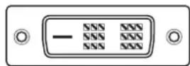
When using a single-link DVI cable, resolution loss (scan line gaps) may occur.
In this case, change the refresh rate to half, or use the supplied dual-link DVI cable.
Luminance equalizer - Digital Uniformity
The Luminance equalizer - Digital Uniformity feature is built in to achieve highly accurate luminance uniformity across the screen. Luminance unevenness is minimized in the final tune-up prior to shipping.
Switchable display mode
The display mode can be switched by menu operations. LMD-DM50: 15M-Independent Sub-pixel Drive or 5M-normal mode
LMD-DM30: 9M-Independent Sub-pixel Drive or 3M-normal mode
LMD-DM20: 6M-Independent Sub-pixel Drive or 2M-normal mode
The display mode can also be switched by optional utility software (Display Utility Software).
1,276-step simultaneously displayable grayscale
Up to 1,276 shades of gray are simultaneously displayable in Independent Sub-pixel Drive display mode using a special viewer. This enables smooth and accurate display of subtle differences in gray shades.
Calibration capability
With the optional calibration sensor and software, luminance and gamma can be corrected automatically. Use the optional LMD-KT10 calibration kit.
Hardware pivoting capability
The LCD panel can also be used in portrait orientation. Hardware-based pivoting is, unlike graphics card- or software-dependent pivoting, much faster with less noise.
Note
Portrait orientation requires a graphics card supporting the resolutions below.
LMD-DM50: 2048 × 2560
LMD-DM30: 1536 × 2048
LMD-DM20: 1200 × 1600
Interchangeable stand
The tilt stand is interchangeable with arm stands featuring a mount plate with 4 holes at 100 mm × 100 mm (4 inches × 4 inches), according to your needs and preferences (page 29).
Automatic detection of LCD panel orientation by gravitation sensor
A built-in gravitation sensor provides for automatic EDID setting, menu screen orientation change and image rotation at less than XGA (1024 × 768) resolution.
Utility Software
The optional calibration kit includes the optional utility software (Display Utility Software) to enhance and maintain the display quality and performance.
Location and Function of Parts and Controls
Front Panel

① (standby) switch
Press to turn on the power in standby mode. Press again to set the unit in standby mode.
Note
Wait at least 10 seconds between switch actions.
②LED indicator
Lights or blinks to indicate the unit status.
| LED | Power | Unit | status |
| Off | OFF | Power | off |
| Off ON Normal (luminance stabilized) | stabilizer on | ||
| Green | ON | Luminance | |
| Blinking green and amber alternately | ON Calibrating | ||
| Amber ON Standby | |||
| Blinking amber ON Advanced power save mode | |||
| Blinking amber twice | ON Error detected. Turn off the unit and consult your Sony dealer. | ||
| Blinking amber three times | ON Error detected. Turn off the unit and consult your Sony dealer. | ||
③LCD luminance sensor
Monitors the LCD luminance.
④ Ambient light sensor
Monitors the ambient light in the unit location.
Rear Panel

①+ (plus) button
Press to display the information (or present operating state) screen. (page 19)
②- (minus) button
Press to display the information (or present operating state) screen. (page 19)
③ DOWN (USB downstream) ports (×2)
Connect the calibration sensor supplied with the optional calibration kit.
When connecting multiple units, connect the UP port (4) of each connected unit. (page 25)
④ UP (USB upstream) port
When using the optional calibration kit, connect this port to the computer. Connect the supplied USB cable between this UP port and the computer's USB port. (page 25)
⑤ DIGITAL (DVI input) connector
Connect the supplied DVI cable. (page 16)
⑥DisplayPort connector
Connect a commercially available DisplayPort cable. (page 16)
⑦ AC IN socket
Connect the supplied AC power cord. (page 16)
⑧ I/O (power) switch
Switches the power on or off. Pressing I supplies power, and pressing O cuts off the power supply.
Adjusting the Stand Height
The tilt stand is locked at the factory. Follow the instructions below to adjust the stand height.
1 Press the tip of the metal rod tool until it clicks. The (spring-loaded) tip of the tool will pop out. 2 Take out the tool and insert it in the socket. 3 Flip the tool up towards "OPEN" to unlock.

4 Adjust the height of the tilt stand.
5 Flip the tool down towards "LOCK" to lock.
Note
For your safety, make sure the tilt stand is locked after adjusting the stand height.

6 Push the tool back in the storage hole (in the tilt stand) until it clicks into place.
The tool will be secured by a hook inside the tilt stand.
Notes
- Keep the tool in the storage hole, so as not to lose it.
- The orientation of the tool must be correct. Check the orientation of the tool when making adjustments and when replacing it in the storage hole. If you insert the wrong end of the tool, the tilt stand will not be locked.
Removing the Connector Cover
1 Unlock the slide latch on the connector cover. 2 Slide the connector cover to the side to remove.

Connecting the Cables
1 Turn off the computer. 2 Connect the supplied DVI cable between the unit's DIGITAL (DVI input) connector and the computer's DVI output connector.
Note
Use the supplied DVI cable only. Otherwise, resolution loss may occur.
When using a DisplayPort cable, connect the DisplayPort cable between the unit's DisplayPort connector and the computer's DisplayPort connector.
Note
The recommended cable length is 2 m (6.6 feet) or less. If you use a long cable, the display may become unstable and flicker.
3 Connect the supplied power cable between the AC IN socket and the wall outlet.
4 Turn on the unit and the computer.

Note
When using the optional calibration kit, connect the supplied USB cable between the unit's UP port and the computer's USB port. For details about connections, refer to the instruction manual for the calibration kit.
Routing the Cables
The cables can be stowed along the tilt stand under the cable cover.
1 Lift the hook at the top of the cable cover, then remove the cable cover from the tilt stand.

2 Secure the cables along the groove at the rear of the tilt stand, and put the cable cover back in place.
Follow steps 3 and 4 to attach the cable cover.

3 Hook the cable cover with two hooks located at the bottom of the tilt stand. (1)
4 Fit on the hook located on the top of the cable cover, and attach the cable cover. (2)

Adjusting the LCD Panel Angle
The LCD panel turns approx. 70° sideways, approx. 3° downward, and approx. 17° upward.
Hold the LCD panel with both hands and adjust the angle slowly.

Switching the LCD Panel Orientation
The LCD panel is locked in portrait orientation when packed at the factory.
Follow the instructions below to switch the LCD panel orientation.
1 Unlock the tilt stand.
For details how to unlock the tilt stand, see page 15.
2 Tilt the LCD panel upward.

3 Lift the LCD panel to the top.

4 Rotate the LCD panel 90°.

5 Lower the LCD panel to the desired height.

6 Lock the tilt stand.
For details how to lock the tilt stand, see page 15.
7 After switching the LCD panel orientation, restart the computer and reset the resolution for the display orientation.
Notes
- Be careful not to pinch your fingers when turning the LCD panel or adjusting its height.
- Turning the LCD panel with cables connected could damage the cables and cause fire or electric shock. Disconnect the power cable and other connected cables before turning the LCD panel.
Displaying the Information Screen
Press the + or - button on the rear panel of the unit so that the information screen appears.
Pressing either button repeatedly changes the display as follows: Information → present operating state → display off.
The information screen automatically turns off after about 15 seconds.
Information

Present operating state

Changing the Display Setting
From the on-screen menu, you can change the four settings below.
For detailed instructions on each setting, see the following pages.
SWITCHING EDID
"Fixing the Display Orientation" (page 20)
SWITCHING DISPLAY MODE
"Switching the Display Mode" (page 21)
SWITCHING INPUT SOURCE
"Switching the Input Source" (page 22)
SWITCHING CONFIGURATION
"Switching Configuration Data" (page 23)
Fixing the Display Orientation
The unit can be used in either portrait or landscape orientation by rotating the panel.
If you use the unit with the display orientation set regardless of the LCD panel orientation, switch the EDID setting on the SWITCHING DATA screen. The default setting is "Auto Selection."
Follow the instructions below to switch the EDID setting.
Switching EDID settings
1. Press either the + or - button on the rear panel once.
The information screen appears.

2. Press and hold the + and - buttons simultaneously for more than 2 seconds.
The SWITCHING EDID screen appears.

3. Press either the + or - button to move the ▶ (cursor), and select an EDID setting.
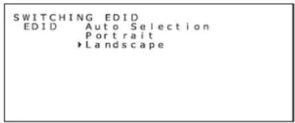
4. Press the + and - button simultaneously for more than 2 seconds.
The information screen appears.
Example when "Landscape" is fixed:
The EDID status switches to "Landscape."

The EDID setting switches to "Fixed."
Notes
- The configuration cannot be switched simply by moving the ▶ (cursor). In order to apply the change, press and hold the + and – buttons simultaneously for more than 2 seconds after moving the cursor.
- The setting change will be canceled if there is no menu operation for more than 15 seconds.
5 Press either the + or - button to close the information screen and exit the setting.
Switching the Display Mode
You can switch between the following display modes:
LMD-DM50
- 5M-normal mode (165 μm pixel pitch)
- ISD* mode (55 µm pixel pitch in the sub-pixel chain direction) developed by the Independent Sub-pixel Drive technology.
LMD-DM30
• 3M-normal mode (207 μm pixel pitch) - ISD* mode (69 µm pixel pitch in the sub-pixel chain direction) developed by the Independent Sub-pixel Drive technology.
LMD-DM20
• 2M-normal mode (270 μm pixel pitch) - ISD* mode (90 µm pixel pitch in the sub-pixel chain direction) developed by the Independent Sub-pixel Drive technology.
The default setting is the ISD* mode. If you use the normal mode, follow the instructions below to switch the display mode.
* ISD is the abbreviation of Independent Subpixel Drive.
1 Press either the + or - button on the rear panel once. The information screen appears.

2 Press and hold the + or - buttons simultaneously for more than 2 seconds.
The SWITCHING EDID screen appears.
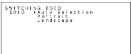
3 Press the ⏻ (standby) switch on the front panel of the unit.
The SWITCHING DISPLAY MODE screen appears.

Pressing the ⏻ (standby) switch repeatedly switches between the SWITCHING EDID and SWITCHING DISPLAY MODE screen.
4 Press either the + or - button to move the ▶ (cursor), and select a display mode.

5 Press and hold the + and - buttons simultaneously for more than 2 seconds.
The information screen appears.
Example when "Normal" is selected:
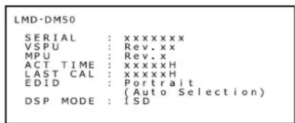
↓

The display mode switches to "Normal."
Notes
- The configuration cannot be switched simply by moving the ▶ (cursor). In order to apply the change, press and hold the + and - buttons simultaneously for more than 2 seconds after moving the cursor.
- The setting change will be canceled if there is no menu operation for more than 15 seconds.
6 Press either the + or - button to close the information screen and exit the setting.
To return to the Independent Sub-pixel Drive mode, follow the steps above and select "ISD" in step 4.
About the Independent Sub-pixel Drive technology license
To display images with the Independent Sub-pixel Drive technology, a license and a special viewer are required. When the license is not activated, the DSP MODE is set as Normal (*) or ISD (*).
When the license is activated, the DSP MODE is set as Normal or ISD.
For details, consult your Sony dealer.
Switching the Input Source
Follow the instructions below to switch the input source.
1 Press either the + or - button on the rear panel.
The information (or present operating state) screen appears.
Pressing either button repeatedly changes the display as follows: Information → present operating state → display off.
The information screen automatically turns off after about 15 seconds.

2 With the above screen displayed, press and hold the + and - buttons simultaneously for more than 2 seconds.
The SWITCHING INPUT SOURCE screen appears.

3 Press either the + or - button to move the ▶ (cursor), and select an input source.

4 Press and hold the + and - buttons simultaneously for more than 2 seconds.
The information (present operating state) screen appears.
Example when "DVI" is selected:

Notes
- The configuration cannot be switched simply by moving the ▶ (cursor). In order to apply the change, press and hold the + and - buttons simultaneously for more than 2 seconds after moving the cursor.
- The setting change will be canceled if there is no menu operation for more than 15 seconds.
5 Press either the + or - button to close the information screen and exit the setting.
Note
The unit automatically detects the input signals. Switch the input source after receiving the video signal from that source.
If the unit has one input source only, the unit always selects that input source regardless of the setting.
Digital input
The unit supports only digital signals. It is normal for noise to occur during startup, shutdown, and/or when switching resolutions. This is a result of the graphics card in the system switching resolution.
Also, when switching resolutions, a white area of 5 mm × 5 mm may appear near the front sensor. In either case, it is not a malfunction.
Note
Do not connect or disconnect the cable during operation, as this could damage the graphics card.
Turn off the system before connecting or disconnecting the cable.
Switching Configuration Data
The unit can save up to three sets of settings (luminance/gamma), which can be called up by selecting a configuration number on the SWITCHING CONFIGURATION screen.
The following three configurations are saved as the factory default. The default setting is “1.”
Follow the instructions below to switch the configuration data.
LMD-DM50/DM30
| Configuration number | Luminance (cd/m2) | Gamma | ||
| Max. | Min. | Ambient Light | ||
| 1 (default) | 410 | 0.8 | 0.0 DICOM | GSDF |
| 2 410 1.0 | 0.0 DICOM | GSDF | ||
| 3 500 0.8 | 0.0 DICOM | GSDF | ||
LMD-DM20
| Configuration number | Luminance (cd/m2) | Gamma | ||
| Max. | Min. | Ambient Light | ||
| 1 (default) | 410 | 0.8 | 0.0 DICOM | GSDF |
| 2 500 | 0.0 DICOM | GSDF | ||
| 3 410 | 0.0 Gamma | 2.2 | ||
Note
To set and save configurations other than above, the optional calibration kit is required.
Switching configuration data
1 Press either the + or - button on the rear panel.
The information (or present operating state) screen appears.
Pressing either button repeatedly changes the display as follows: Information → present operating state → display off.
The information screen automatically turns off after about 15 seconds.

2 With the above screen displayed, press and hold the + and - buttons simultaneously for more than 2 seconds.
The SWITCHING INPUT SOURCE screen appears.

3 Press the ⏻ (standby) switch on the front panel of the unit.
The SWITCHING CONFIGURATION screen appears.

Pressing the ⏻ (standby) switch repeatedly switches between the SWITCHING INPUT SOURCE and SWITCHING CONFIGURATION screen.
4 Press either the + or - button to move the ▶ (cursor), and select a configuration number.

5 Press and hold the + and - buttons simultaneously for more than 2 seconds.
The information (present state) screen appears.
Example when "2" is selected:

Configuration number 2 is selected.
Notes
- The configuration cannot be switched simply by moving the ▶ (cursor). In order to apply the change, press and hold the + and - buttons for more than 2 seconds after moving the cursor.
- The setting change will be canceled if there is no menu operation for more than 15 seconds.
6 Press either the + or - button to close the information screen and exit the setting.
Operating the Menu with No Image Input
If no signal is input, the unit usually enters the standby mode due to the power management function. Normal power can be temporarily restored for menu operations by the following method.
Displaying the menu screen
1 In the standby mode (the LED indicator of the ⏻ (standby) switch is lit in amber), press and hold the + or - buttons on the rear panel simultaneously for more than 2 seconds.

The LED indicator lights up in green and the information screen appears.

You can change the following settings from the menu.
SWITCHING EDID
"Fixing the Display Orientation" (page 20)
SWITCHING DISPLAY MODE
"Switching the Display Mode" (page 21)
SWITCHING INPUT SOURCE
"Switching the Input Source" (page 22)
SWITCHING CONFIGURATION
"Switching Configuration Data" (page 23)
Note
The power only turns on momentarily, then the standby mode is entered. If you happen to enter the standby mode during menu operation, perform step 1 again.
About the power management function
The unit enters standby mode if no signal input is detected to reduce power consumption.
To set the function
Use the screensaver function (equipped with a calibration kit) for use with Windows.
Using a USB Hub
The unit has a USB hub. Connect the supplied USB cable between the unit and the computer. You can also connect multiple units in a chain, or connect the calibration sensor to the unit directly.
Notes
- This USB hub is only for use with an LMD-DM series LCD Display and the optional calibration sensor.
- Proper operation of all USB devices connected to the USB hub is not guaranteed.
1 Connect the supplied DVI cable between the unit and computer, and turn on the computer (page 16).
2 Connect the supplied USB cable between the unit's UP (USB upstream) port and the computer's (or another USB hub's) USB down (USB downstream) port.
The USB function is automatically set up.

Connecting the supplied USB cable also enables the following:
- To calibrate the unit (An optional calibration kit is required.) • To calibrate multiple units in a chain
To calibrate the unit
Connect the supplied USB cable between the unit's UP (USB upstream) port and the computer's USB down (USB downstream) port.
For more information, refer to the instruction manual for the calibration kit.
To calibrate multiple units in a chain
Up to six units can be connected using the USB cables.
1 Connect the supplied USB cable between the 1st unit's UP (USB upstream) port and the computer's USB down (USB downstream) port. 2 Connect the supplied USB cable between the 1st unit's DOWN (USB downstream) port and the 2nd unit's UP (USB upstream) port. 3 Repeat step 2 to connect the 3rd, 4th, and 5th unit in the same way. 4 Connect the supplied USB cable between the 6th unit's UP (USB upstream) port and the computer's USB down (USB downstream) port.
![graph TD subgraph "1st unit2nd3rd" A["Computer"] --> B["4th5th6th"] B --> C["4th5th6th"] C --> D["4th5th6th"] D --> E["4th5th6th"] E --> F["4th5th6th"] F --> G["4th5th6th"] G --> H["4th5th6th"] H --> I["4th5th6th"] I --> J["4th5th6th"] J --> K["4th5th6th"] K --> L["4th5th6th"] L --> M["4th5th6th"] M…](/content/2026/06/1363466/images/d4a21d5c1836e23a1f5978882fc3c52c8539b0df7d437e18e16a1ee9d14b8927.jpg)
Note
Up to five units can be connected in a daisy chain.
Connector Pin Assignment
DIGITAL
DVI 24-pin (female) connector

| Pin number Functions | ||
| 1 | TMDS | Data |
| 2 | TMDS | Data |
| 3 TMDS Data 2/4 Shield | ||
| 4 | TMDS | Data |
| 5 | TMDS | Data |
| 6 | DDC | Clock |
| 7 DDC Data | ||
| 8 | (NC) | |
| 9 | T | M |
| 10 TMDS Data 1+ | ||
| 11 TMDS Data 1/3 Shield | ||
| 12 | TMDS Data 3-* | |
| 13 | TMDS Data 3+* | |
| 14 +5 V Power | ||
| 15 | GND | |
| 16 Hot Plug Detect | ||
| 17 | TMDS Data 0- | |
| 18 | TMDS Data 0+ | |
| 19 TMDS Data 0/5 Shield | ||
| 20 | TMDS Data 5-* | |
| 21 | TMDS Data 5+* | |
| 22 TMDS Clock Shield | ||
| 23 TMDS Clock+ | ||
| 24 | TMDS Clock- | |
* (NC) for LMD-DM20
DisplayPort
DisplayPort receptacle connector

| Pin number Functions | ||
| 1 ML_Lane 3(n) | ||
| 2 | GND | |
| 3 ML_Lane 3(p) | ||
| 4 | ML_Lane | 2(n) |
| 5 | GND | |
| 6 | ML_Lane | 2(p) |
| 7 ML_Lane 1(n) | ||
| 8 | GND | |
| 9 ML_Lane 1(p) | ||
| 10 ML_Lane 0(n) | ||
| 11 GND | ||
| 12 ML_Lane 0(p) | ||
| 13 CONFIG1 | ||
| 14 CONFIG2 | ||
| 15 AUX CH(p) | ||
| 16 | GND | |
| 17 AUX CH(n) | ||
| 18 Hot Plug Detect | ||
| 19 Return | ||
| 20 DP_PWR | ||
UP (USB)
USB B-type receptacle connector

| Pin number Functions | |
| 1 | VCC |
| 2 -DATA | |
| 3 +DATA | |
| 4 | GND |
DOWN (USB)
USB A-type receptacle connector

| Pin number Functions | |
| 1 | VCC |
| 2 -DATA | |
| 3 +DATA | |
| 4 | GND |
Available display resolution
| LMD-DM50 | LMD-DM30 | LMD-DM20 | |
| DSP MODE VGA to XGA (regardless) | |||
| Normal (pixel × pixel) | 2048 × 25602560 × 2048 | 1536 × 20482048 × 1536 | 1200 × 16001600 × 1200 |
| ISD (pixel × pixel) | 2048 × 7680(2560 × 3)7680 (2560 × 3) × 2048 | 1536 × 6144(2048 × 3)6144 (2048 × 3) × 1536 | 1200 × 4800(1600 × 3)4800 (1600 × 3) × 1200 |
| Fv=25 Hz/50Hz | Fv=30 Hz/60Hz | Fv=30 Hz/60Hz | |
"UNSUPPORTED_TIMING" appears on the menu screen if an unsupported signal is input.
Troubleshooting
Check the following chart before consulting your Sony dealer.
| Symptom Cause and Solution | |
| The unit will not turn on.(The LED indicator is off.) | Make sure the unit is plugged in (page 16).Check if the I/O (power) switch is turned on. |
| The power is turned off, but the LED indicator stays lit. | Even when the I/O (power) switch is turned off in the standby mode, the LED indicator stays lit for a few seconds. This is not a malfunction. |
| The screen does not come on. • Check if the cables are connected correctly.• Check if the computer is turned on.• If the LED indicator is lit in amber, the computer may be in the standby mode. Press any key on the keyboard to activate the computer.• The input signal frequency or display resolution may not be appropriate for the specifications of the unit. Refer to the computer instruction manual and adjust the frequency and/or resolution.• If the LED indicator blinks twice or three times, there may be an error occurring. Contact your Sony dealer. | |
| Images are not displayed properly. • The display resolution for a given input signal may not be appropriate for the specifications of the unit. Refer to the computer instruction manual and adjust resolution. | |
| When you turn off the unit while using the DisplayPort input, the display becomes unstable. | Data is sent by the DisplayPort while the computer is running. Do not turn off the unit while receiving a DisplayPort signal.Do not turn off the unit while the computer is running. Even if the unit is turned on again, the screen might become unstable. Turn on the computer after turning on the unit. |
| Images via the DisplayPort input are not displayed properly. | A DisplayPort input signal might not be displayed properly, depending on the combinations of graphics card, driver, OS, etc. For recommended graphics cards, consult your dealer. |
| Resolution loss (scan line gaps) occurs when using dual-link mode (LMD-DM50/DM30). | It can happen when a single-link DVI cable is used. Use the supplied dual-link DVI cable (page 11). |
| The mouse cursor does not move smoothly. • Check the refresh rate (Fv) of the display mode.The following setting will enable smooth movement:Fv = 50 Hz for LMD-DM50Fv = 60 Hz for LMD-DM30/DM20For details about the setting method, refer to the instruction manual for the graphics card. | |
Attaching an Arm Stand
The tilt stand is interchangeable with commercially available arms that feature the following:
Mount plate with 4 holes at 100 mm × 100 mm.
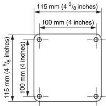
Load capacity should be at least equal to the total mass of the LCD panel (without stand) and connected cables.
For more information, ask the arm maker.
Notes
- Use the original screws to attach the LCD panel on its original tilt stand again.
- If the screws are too long, they could damage internal parts. If they are too short, the attachment may become loose and the LCD panel could fall off.
Choose the screw size carefully according to the plate thickness.
| Mounting plate thickness Screw size |
| 3.5 - 4.5 mm ISO M4 × 12 |
| 1.5 - 3.5 mm ISO M4 × 10 (Originally used) |
| Below 1.5 mm ISO M4 × 8 |
Sony is not liable for any damage or injury resulting from changing stands.
How to attach an arm stand
1. Place a soft cloth or cushioning material over a stable, even surface. 2. Put the LCD panel face down on the cushioning material.
3. Remove the 4 screws, using a cross-head screwdriver, then detach the tilt stand.

4. Attach the arm stand to the LCD panel, reversing the procedure above.
Do not try by yourself to attach the LCD panel to an arm that is already installed somewhere. Ask for assistance from another person. Tipping over or dropping the LCD panel could cause damage and/or injury.
Anti-Theft Security Slot
The unit is equipped with a security slot supported by MicroSaver Security Lock System by Kensington Technology Group. MicroSaver locks are available at PC supply stores.

Kensington is a registered trademark of Kensington Technology Group.
Specifications
Picture performance
Panel: a-Si TFT Active Matrix LCD
(Monochrome)
Picture size (diagonal)
LMD-DM50/DM20: 21 3/8 inches
LMD-DM30: 20 7/8 inches
Effective picture size (H × V)
LMD-DM50: 422.4 × 337.9 mm
(16 3/4 × 13 3/8 inches)
LMD-DM30: 423.9 × 318.0 mm
(16 3/4 × 12 5/8 inches)
LMD-DM20: 432.0 × 324.0 mm
(17 1/8 × 12 7/8 inches)
Resolution (H × V)
LMD-DM50:
Landscape 2560 × 2048 pixels
(QSXGA)
Portrait 2048 × 2560 pixels
LMD-DM30:
Landscape 2048 × 1536 pixels
(QXGA)
Portrait 1536 × 2048 pixels
LMD-DM20:
Landscape 1600 × 1200 pixels
(UXGA)
Portrait 1200 × 1600 pixels
Aspect LMD-DM50:
Landscape 5:4
Portrait 4:5
LMD-DM30/DM20:
Landscape 4:3
Portrait 3:4
Pixel efficiency 99.99%
Backlight CCFL
Standard luminance/panel specifications
| LMD-DM50 | LMD-DM30 | LMD-DM20 | |
| Max. luminance | 1,100 cd/m 2 | 1,000 cd/m 2 | 1,800 cd/m 2 |
| Max. contrast 85° | 0:1 (typ) 900:1 | (typ) 700:1 (typ) | |
| Max. viewing angle* | 85°/85°/85°/85° | ||
* LMD-DM50: up/down/left/right, contrast ≥ 20:1 LMD-DM30/DM20: up/down/left/right, contrast ≥ 10:1
Factory default (LMD-DM50/DM30)
| Configuration number | Luminance (cd/m2) | Gamma | ||
| Max. | Min. | Ambient Light | ||
| 1 (default) | 410 | 0.8 | 0.0 DICOM | GSDF |
| 2 410 1.0 | 0.0 DICOM | GSDF | ||
| 3 500 0.8 | 0.0 DICOM | GSDF | ||
Factory default (LMD-DM20)
| Configuration number | Luminance (cd/m2) | Gamma | ||
| Max. | Min. | Ambient Light | ||
| 1 (default) | 410 | 0.8 | 0.0 DICOM | GSDF |
| 2 500 | 0.0 DICOM | GSDF | ||
| 3 410 | 0.0 Gamma | 2.2 | ||
Input
DVI-D DVI-D (×1)
LMD-DM50/DM30: TMDS Dual link
LMD-DM20: TMDS Single link
DisplayPort DisplayPort connector (×1)
USB hub UP stream (×1)
DOWN stream (×2)
General
Power requirements
AC 100 V to 240 V, 50/60 Hz, 1.5 A to 0.6 A
Power consumption
LMD-DM50/DM30: Approx. 90 W typ
LMD-DM20: Approx. 85 W typ
Operating conditions
Temperature
5°C to 40°C (41°F to 104°F)
Recommended temperature
20°C to 30°C (68°F to 86°F)
Humidity 30% to 80% (no condensation)
Pressure 700 hPa to 1,060 hPa
Storage and transport conditions
Temperature
-20°C to +60°C (-4°F to +140°F)
Humidity 10% to 85% (no condensation)
Pressure 266 hPa to 1,060 hPa
Mass LMD-DM50: Approx. 12.3 kg (27 lb 1.9 oz)
LMD-DM30: Approx. 11.6 kg (25 lb 9.2 oz)
LMD-DM20: Approx. 12.0 kg (26 lb 7.3 oz)
(including tilt stand of approx. 4.2 kg (9 lb 4.2 oz))
Supplied accessories
AC power cord (1)
DVI cable (Dual link) (LMD-DM50/DM30) (1)
DVI cable (Single link) (LMD-DM20) (1)
USB cable (1)
CD-ROM (1)
Before Using this Unit (1)
Sales Companies Guide (1)
Optional accessories
Calibration Kit LMD-KT10
Display Network Manager LMD-SN10
Medical Specifications
Protection against electric shock:
Class I
Protection against harmful ingress of water: Ordinary
Degree of safety in the presence of a flammable anesthetic mixture with air or with oxygen or nitrous oxide:
Not suitable for use in the presence of a flammable anesthetic mixture with air or with oxygen or nitrous oxide
Mode of operation:
Continuous
Design and specifications are subject to change without notice.
Note
Always verify that the unit is operating properly before use. SONY WILL NOT BE LIABLE FOR DAMAGES OF ANY KIND INCLUDING, BUT NOT LIMITED TO, COMPENSATION OR REIMBURSEMENT ON ACCOUNT OF THE LOSS OF PRESENT OR PROSPECTIVE PROFITS DUE TO FAILURE OF THIS UNIT, EITHER DURING THE WARRANTY PERIOD OR AFTER EXPIRATION OF THE WARRANTY, OR FOR ANY OTHER REASON WHATSOEVER.
Dimensions
LMD-DM50
Front (portrait)

Side (portrait)

Front (landscape)

Side (landscape)

LMD-DM30/DM20
Front (portrait)

Side (portrait)

Front (landscape)
Side (landscape)
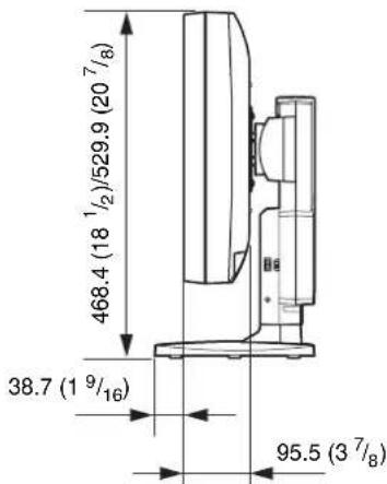
Unit: mm (inches)

- OWNER'S RECORD
- WARNING
- WARNING THIS APPARATUS MUST BE EARTHED
- FOR THE CUSTOMERS IN THE U.S.A
- DECLARATION OF CONFORMITY
- FOR THE CUSTOMERS IN CANADA
- FOR THE CUSTOMERS IN THE U.S.A AND CANADA
- FOR THE CUSTOMERS IN EUROPE
- IMPORTANT SAFEGUARDS/NOTICES FOR USE IN THE MEDICAL ENVIRONMENTS
- CAUTION
- FOR THE CUSTOMERS IN THE USA
- WARNING ON POWER CONNECTION
- WARNING ON POWER CONNECTION FOR MEDICAL USE
- SYMBOLS ON THE UNIT
- REFER TO THE OPERATING INSTRUCTIONS
- IMPORTANT EMC NOTICES FOR USE IN THE MEDICAL ENVIRONMENTS
- TABLE OF CONTENTS
- PRECAUTION
- FEATURES
- LOCATION AND FUNCTION OF PARTS AND
- CONTROLS
- ADJUSTING THE STAND HEIGHT
- ON SAFETY
- ON INSTALLATION
- ABOUT THE LCD PANEL
- PROTECTIVE FILTER
- ON BURN-IN
- TO REDUCE THE RISK OF BURN-IN
- ON LONG PERIODS OF USE
- ON CLEANING
- DISPOSAL OF THE UNIT
- RECOMMENDATION TO USE MORE THAN ONE UNIT
- ON REPACKING
- ON MOISTURE CONDENSATION
- HAVING THE UNIT PERIODICALLY CLEANED
- ABOUT THE POWER ON/OFF
- ABOUT THIS MANUAL
- SUPER-HIGH RESOLUTION OF INDEPENDENT SUB PIXELS
- NOTE
- DISPLAYPORT
- ULTRA-HIGH-DEFINITION MONOCHROME LCD PANEL
- HIGH LUMINANCE, HIGH CONTRAST
- DUAL-LINK SUPPORT (LMD-DM50/DM30)
- DVI CABLE CONNECTOR (MALE)
- LUMINANCE EQUALIZER - DIGITAL UNIFORMITY
- SWITCHABLE DISPLAY MODE
- STEP SIMULTANEOUSLY DISPLAYABLE GRAYSCALE
- CALIBRATION CAPABILITY
- HARDWARE PIVOTING CAPABILITY
- INTERCHANGEABLE STAND
- AUTOMATIC DETECTION OF LCD PANEL ORIENTATION BY GRAVITATION SENSOR
- UTILITY SOFTWARE
- LOCATION AND FUNCTION OF PARTS AND CONTROLS
- FRONT PANEL
- ① (STANDBY) SWITCH
- ②LED INDICATOR
- ③LCD LUMINANCE SENSOR
- ④ AMBIENT LIGHT SENSOR
- REAR PANEL
- NOTES
- REMOVING THE CONNECTOR COVER
- CONNECTING THE CABLES
- ROUTING THE CABLES
- ADJUSTING THE LCD PANEL ANGLE
- SWITCHING THE LCD PANEL ORIENTATION
- DISPLAYING THE INFORMATION SCREEN
- INFORMATION
- PRESENT OPERATING STATE
- CHANGING THE DISPLAY SETTING
- SWITCHING EDID
- SWITCHING DISPLAY MODE
- SWITCHING INPUT SOURCE
- SWITCHING CONFIGURATION
- FIXING THE DISPLAY ORIENTATION
- SWITCHING EDID SETTINGS
- SWITCHING THE DISPLAY MODE
- LMD-DM
- ABOUT THE INDEPENDENT SUB-PIXEL DRIVE TECHNOLOGY LICENSE
- SWITCHING THE INPUT SOURCE
- DIGITAL INPUT
- SWITCHING CONFIGURATION DATA
- OPERATING THE MENU WITH NO IMAGE INPUT
- DISPLAYING THE MENU SCREEN
- ABOUT THE POWER MANAGEMENT FUNCTION
- TO SET THE FUNCTION
- USING A USB HUB
- TO CALIBRATE THE UNIT
- TO CALIBRATE MULTIPLE UNITS IN A CHAIN
- CONNECTOR PIN ASSIGNMENT
- DIGITAL
- UP (USB)
- DOWN (USB)
- TROUBLESHOOTING
- ATTACHING AN ARM STAND
- LOAD CAPACITY SHOULD BE AT LEAST EQUAL TO THE TOTAL MASS OF THE LCD PANEL (WITHOUT STAND) AND CONNECTED CABLES
- HOW TO ATTACH AN ARM STAND
- ANTI-THEFT SECURITY SLOT
- SPECIFICATIONS
- PICTURE PERFORMANCE
- INPUT
- GENERAL
- MEDICAL SPECIFICATIONS
- DIMENSIONS
Brand : SONY
Model : LMD-DM20
Category : Monitor