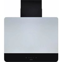
EXA60SI - Range hood CDA - Free user manual and instructions
Find the device manual for free EXA60SI CDA in PDF.


| Product Type | Under-cabinet range hood |
| Brand | CDA |
| Model | EXA60SI |
| Width | 60 cm |
| Depth | 50 cm |
| Height (min-max) | 10-40 cm (adjustable) |
| Weight | 12 kg |
| Power Supply | 220-240 V ~ 50 Hz |
| Total Power Consumption | 240 W |
| Motor Power | 200 W |
| Lighting | 2 x 3 W LED |
| Number of Speeds | 3 speeds + intensive boost |
| Max Airflow | 650 m³/h |
| Noise Level (max speed) | 65 dB(A) |
| Filter Type | Aluminum grease filter (dishwasher safe) |
| Controls | Touch-sensitive buttons |
| Material | Stainless steel |
| Installation Type | Wall-mounted or under cabinet |
| Venting Type | Ducted (recirculation possible with charcoal filter) |
| Air Duct Diameter | 150 mm |
| Energy Class | A+ |
| Grease Filter Efficiency Class | B |
| Fluid Dynamic Efficiency Class | A |
| Lighting Efficiency Class | A |
| Annual Energy Consumption | 50 kWh/year |
Frequently Asked Questions - EXA60SI CDA
User questions about EXA60SI CDA
0 question about this device. Answer the ones you know or ask your own.
Ask a new question about this device
Download the instructions for your Range hood in PDF format for free! Find your manual EXA60SI - CDA and take your electronic device back in hand. On this page are published all the documents necessary for the use of your device. EXA60SI by CDA.
USER MANUAL EXA60SI CDA
Installation, use and maintenance
Contents:
3 Important
4 Important information
6 Using your extractor
7 Care and maintenance
7 Removing the grease filter
8 Changing/fitting the charcoal filter(s)
9 Changing the light
10 - 17 Installation
10 Installation preparation - height
12 Ducting and ventilation
14 Mounting the extractor
16 Alternative to the chimney sections
16 Using the 'T-piece' for recirculation
17 Securing the chimney sections
18 Mains electricity connection
20 Electrical information
21 Troubleshooting
23 Energy Efficiency Information
Important
The CDA Group Ltd cannot be held responsible for injuries or losses caused by incorrect use or installation of this product. Please note that CDA reserve the right to invalidate the guarantee supplied with this product following incorrect installation or misuse of the appliance or use in a commercial environment.
This appliance is not designed to be used by people (including children) with reduced physical, sensorial or mental capacity, or who lack experience or knowledge about it, unless they have had supervision or instructions on how to use the appliance by someone who is responsible for their safety.
Under no circumstances should any external covers be removed for servicing or maintenance except by suitably qualified personnel.
Appliance information:
Please enter the details on the appliance rating plate below for reference, to assist CDA Customer Care in the event of a fault with your appliance and to register your appliance for guarantee purposes.
| Appliance Model |
| Serial Number |
EU Declarations of Conformity:
This appliance has been designed, constructed and marketed in compliance with safety requirements of EU Directive 2014/35/EU (LVD)
and requirements of EU Directive 2014/30/EU (EMC).
IMPORTANT INFORMATION FOR CORRECT DISPOSAL OF THE PRODUCT IN ACCORDANCE WITH EC DIRECTIVE 2012/19/EU.
At the end of its working life, the product must be taken to a special local authority waste collection centre or to a dealer providing appliance recycling services.
Disposing of a household appliance separately avoids possible negative consequences for the environment and health. It also enables the constituent materials to be recovered, saving both energy and resources. As a reminder of the need to dispose of household appliances separately, the product is marked with a crossed-out wheeled dustbin. ✗
Please note:
- Under no circumstances should the extractor be connected to any gas ventilation system, flue system or hot air ducting system.
- Do not vent the extractor into an attic or loft space.
- Only house the extractor in rooms with adequate ventilation. Remember that the extractor is powerful and whatever air is extracted needs to be replaced.
- Do not tile the extractor in. It should be removable for service or maintenance.
- Do not use silicone sealant to secure the hood to the wall.
-
You must be able to isolate the extractor from the mains electrical supply after installation.
-
This extractor has been designed to be used in a room with a volume of less than 36m^3 .
- Steam cleaners must not be used when cleaning this appliance.
- The performance of your extractor will vary depending on a number of factors. These include: type of extraction, length of ducting, room volume, ventilation available and cleanliness of the filters.
Using your extractor
For best performance, you should switch on the extractor 15 minutes before starting to cook and leave it to run for approximately 15 minutes after the end of cooking.

Control Panel (Fig. 1)
A - Light key
B - Speed decrease key
C - Speed increase key
D - Timer key
To switch the extractor light on or off
- Press the light key (A).
To switch on the extractor or to change the speed
- Press the speed increase key to switch the unit on. Adjust the speed as necessary using keys B and C. The circular indicators will illuminate progressively for the first, second, third or intensive speed levels to indicate which is active.
- Press the timer key (D) to activate a 10 minute timer for that speed. The selected speed's indicator should flash whilst the timer is active. Touch the same sensor to cancel the timer. Please note that the intensive speed automatically switches to speed 3 after 6 minutes (see page 21 for more information).
To switch the extractor off
- Use the speed decrease key until no speed indicators are on.
Care and maintenance
IMPORTANT: DO NOT PERFORM MAINTENANCE OR CLEANING OF THE EXTRACTOR WITHOUT FIRST SWITCHING OFF THE ELECTRICITY SUPPLY.
Cleaning
You should use a non-abrasive cleaner. Any abrasive cleaner (including Cif) will scratch the surface and could erase the control panel markings.
You can clean your extractor effectively by simply using a dilute solution of water and mild detergent and drying to a shine with a clean cloth.
IMPORTANT:
Always protect surfaces immediately beneath the extractor (such as a hob) with clean, dry towels or similar cushioning items before carrying out any cleaning or maintenance in case of falling parts/items.
Removing and cleaning the grease filter
The grease filter should be kept clean to minimise the risk of fire. At least once a month you should remove and clean the grease filter with hot soapy water. You can also wash the grease filter in a dishwasher, ensuring that you place it in an upright position to prevent damage from other items in the dishwasher. After rinsing and drying, replace the filter. Cleaning the grease filter in the dishwasher may lead to discolouration. This is normal and does not constitute a fault with the appliance.
Please note: After 30 hours of usage all speed indicators will flash to signal that the filter needs to be cleaned. Press the timer key to reset after cleaning.
To remove the grease filter, lift open the extractor cover and then release the catch on the handle on the grease filter. It will release at the handle side. Lift it towards you slightly and then lower the grease filter to remove it completely. To replace the grease filter, repeat the steps in reverse.
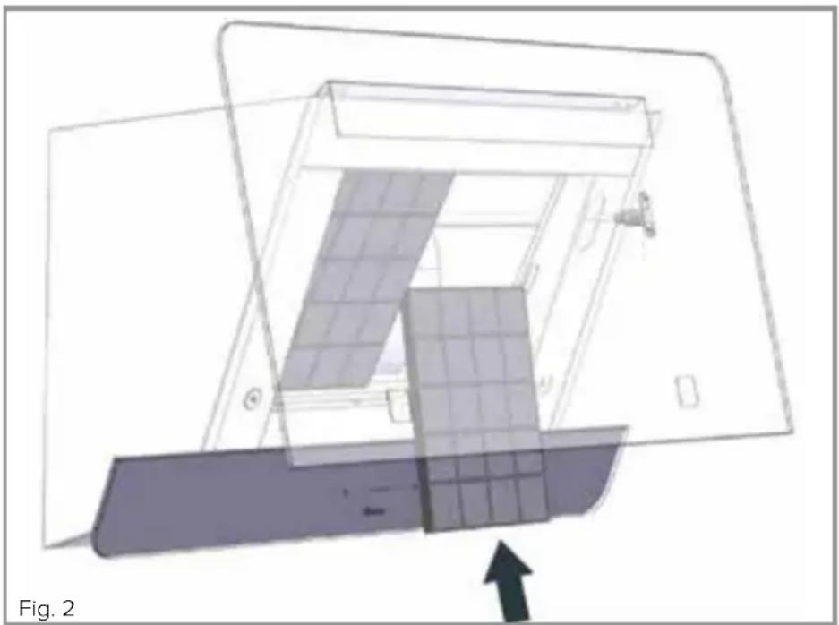
Changing the charcoal filter (re-circulating only) - Fig. 2
To ensure best performance of your extractor, you should replace the charcoal filter every four to six months, depending on use. To attach a new charcoal filter, first remove the grease filter as described above. Remove any old charcoal filters that are in place. Take a new charcoal filter and fit it into position behind where the grease filter sits. Use the structural screws in the filter aperture to hold the charcoal filter in place. Repeat this process with the remaining side and then re-fit the grease filter.
natural_image
Diagram of a solar panel installation with an arrow indicating direction (no text or symbols)Changing the light
This appliance is fitted with energy saving LED lighting that has a considerably longer life expectancy than traditional filament bulbs. These are not user-replaceable. In the unlikely event of a failure please contact CDA Customer Care using the details on page 22.
Do not touch bulbs or adjacent areas during or straight after prolonged use of the lights.
The light is designed for use during cooking and not for general room illumination.
Extended use of the light can reduce the life span.
Installation
When installing this product we recommend you seek the help of another individual. This product may have some sharp edges. Please take care and wear adequate PPE when handling.
Installation preparation - height
When the extractor is to be installed above an electric hob, the minimum distance between the hob and the bottom edge of the extractor must exceed 495mm.
When the extractor is to be installed above a gas hob, the minimum distance between the bottom edge of the extractor and hob must exceed 495mm.
If the instructions provided with your gas hob state that the required distance between the hob and extractor must be greater than our measurement, then that is the distance that should be observed; this is a legal requirement and may lead to your hob being disconnected from the gas supply and the installation being reported under RIDDOR (the height should be measured from the top of the burners).
IN THE ABSENCE OF ANY INSTRUCTIONS SUPPLIED WITH THE GAS HOB, THE MINIMUM DISTANCE BETWEEN THE HOB AND EXTRACTOR MUST BE AT LEAST 760mm. The width of any hob must not be greater than the width of the extractor installed above it.
There are images showing the extractor dimensions for both models below (Fig. 3). This is intended to help with preparation for installing the extractor.
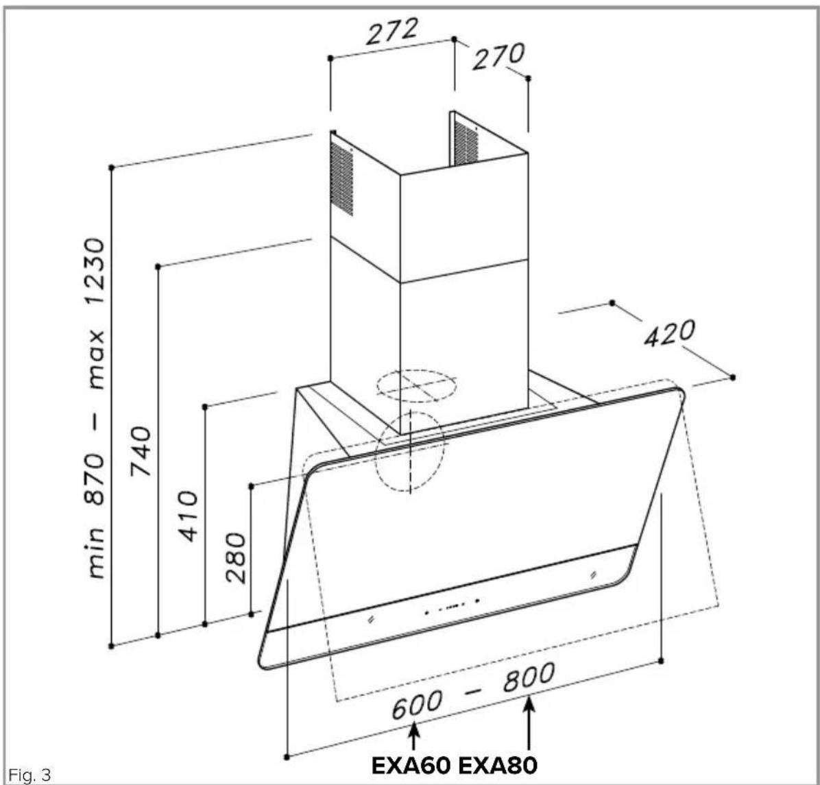
Taking into account the extractor dimensions, and the advice regarding installation height as per page 10, roughly mark the centre line for the extractor.
Use the supplied template to finalise the extractor's position before using a pencil or similar to mark the mounting bracket and screw hole positions (denoted by ∅8mm hole markings on the template).
Ducting and ventilation
For best performance and lowest noise output, we recommend the use of 150mm ducting. You can also use smaller diameter ducting but this will reduce performance and potentially increase the noise level of the extractor whilst in use. In general, the less ducting you use (i.e. distance and bends) the more efficient your extractor will be.
This extractor offers two options for ducting out - through a wall and through the ceiling. The factory setup is for ducting through the ceiling but the motor can be easily rotated to minimise on bends in ducting and therefore maximise efficiency. To swap the motor for horizontal (through a wall) ducting, follow the steps below:
Whilst supporting the motor group, remove all screws shown in Fig. 4. Ensure that there is no power being supplied to the appliance during the installation process.
Flip the motor and motor plate and re-fit the screws (Fig. 5). If you need to access the inside of the appliance at this stage, use a small flathead screwdriver or similar tool to pop the collar out/off the knuckle of the hydraulic strut holding the extractor cover in place. The knuckle will then be easily removable. Ensure that someone is helping you who can hold the cover open for you. Remember to re-fit and secure the hydraulic strut knuckle and collar.
With the desired motor orientation, prepare the ducting outlet area. You may wish to fit the chimney installation bracket and screws first.
Before cutting/drilling through any surfaces, ensure that adequate measures have been taken to ensure no electrical cables or similar lie behind.

natural_image
Technical diagram of a mechanical assembly with directional arrows indicating motion or force, no readable text or symbols present.
natural_image
Technical illustration of a mechanical component with a circular opening and mounting brackets (no text or symbols)Mounting the extractor
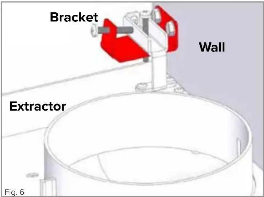
Once you are content with the prepared area, drill out the holes indicated by ∅8mm markings on the template and insert wall plugs. The two pairs of holes in the upper half of the supplied template are where the fixing brackets will go. Fit these brackets now (but do not mount the extractor yet). These should be fitted to the wall as per Fig. 6. They will act as support hooks for the extractor body.
When both brackets have been firmly secured to the wall, manoeuvre the extractor body onto the brackets as per Fig. 6. Take care not to lift the extractor by the front lid/cover.
Tighten the screw marked ‘A’ in Fig. 7 on both sides.
If the extractor is not sitting level, use screws marked as 'B' in Fig. 7 and adjust as necessary to achieve the desired seating.

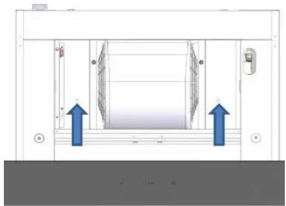
Next, secure the extractor body to the wall via the pre-drilled holes on the extractor's interior. You may need to disengage the hydraulic strut to do this, use a small flathead screwdriver or similar tool to pop the collar out/off the knuckle of the hydraulic strut. The knuckle will then be easily removable. Ensure that someone is helping you who can hold the cover open for you. Remove the grease filter and fit two screws, with one each side as per Fig. 8.
natural_image
Technical diagram of a mechanical or electrical enclosure with two blue arrows indicating directional movement (no text or symbols present)Fig. 8
Please note, when preparing for connecting the extractor to the mains power supply, that the electrical connection to the extractor should not be located inside the boundaries of the chimney. This is especially important if the extractor is to be used in recirculation mode. There must be an isolation switch, which is easily accessible after installation, so that the extractor can be disconnected from the mains electrical supply.
Alternative to chimney sections
If you are re-circulating the extracted air through charcoal filters, or if you have flipped the motor to extract horizontally through a wall, then you do not need to fit the chimney sections (though you can still fit them as per page 17 should you wish). If you decide not to use the chimney sections, fit the outlet grid, as shown in Fig. 9.

natural_image
Diagram showing a device being lowered into a housing, with a red arrow indicating the process (no text or symbols present)IMPORTANT: If the motor outlet is still positioned vertically (pages 12 and 13), you must remove the non-return flaps from the motor outlet before fitting the outlet grid.
These are pictured to the right in Fig. 10. Keep the flaps, and the spring that holds them in position, safe in case they are needed in the future.

natural_image
Top-down view of a black circular device with red arrows pointing to its central vertical structure, labeled 'Fig. 10' (no text or symbols on the device itself)Securing the chimney sections
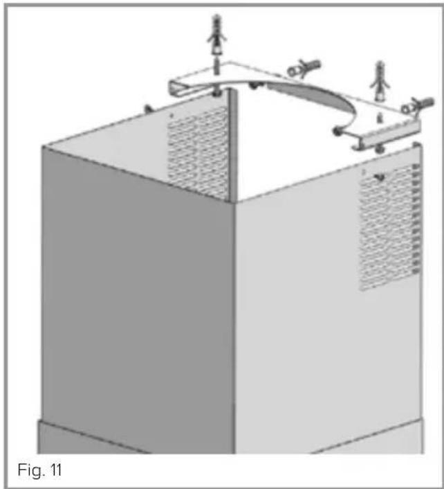
If you are ducting the extracted air outside and/or fitting the chimney sections, place the chimney securing bracket (Fig. 11) at the appropriate height. Mark the holes for the screws with which the bracket will be secured to the wall (or ceiling - the bracket also offers this option). Drill out the holes and fit wall plugs. Secure the bracket to the wall or ceiling and then raise the inner chimney piece to the required height. Secure the inner chimney piece to the chimney bracket using two small screws (Fig. 11).
natural_image
3D diagram of a mechanical assembly with two vertical components and mounting brackets, labeled Fig. 11 (no text or symbols on the diagram itself)Using the ‘T-piece’ for recirculation
If you are using the chimney sections but re-circulating the extracted air through charcoal filters, then you will need to purchase and fit the 'T-piece' as per Fig. 12. This is available from the CDA Sales team under code RTP01.
If re-circulating, ensure that the charcoal filters are fitted as per page 8.
You can then fit the chimneysections as per the above.

natural_image
3D diagram of a mechanical assembly with a component being lifted, showing a cylindrical part inside a housing (no text or symbols)Mains electricity connection
THIS APPLIANCE COMES FITTED WITH A 3 PIN PLUG, CONTAINING A 3A FUSE, BUT CAN BE CONNECTED TO THE MAINS SUPPLY BY A COMPETENT PERSON, USING FIXED WIRING VIA A DOUBLE POLE SWITCHED FUSED SPUR OUTLET
AND PROTECTED BY A 3A FUSE.
If hard-wiring, we recommend that the appliance is connected by a qualified electrician, who is a member of the N.I.C.E.I.C. and who will comply with the I.E.E. and local regulations.
The wires in the mains lead of this appliance are coloured in accordance with the following code:

BLUE = NEUTRAL, BROWN = LIVE, GREEN+YELLOW = EARTH
As the colours of the wires in the mains lead for the appliance may not correspond with the coloured markings identifying the terminals connecting to the fused spur, proceed as follows:
- The wire which is coloured blue must be connected to the terminal marked N (Neutral), or coloured black.
- The wire which is coloured brown must be connected to the terminal marked L (Live), or coloured red.
- The wire coloured green and yellow must be connected to the terminal marked E (Earth) or coloured green or green and yellow.
Assembly and electrical connection should be carried out by competent personnel.
The mains lead of this appliance has been fitted with a BS 1363A 3A fused plug. To change a fuse in this type of plug, follow the steps below:
- Remove the fuse cover and fuse.
- Fit replacement 3A fuse, ASTA approved to BS 1362 type, into the fuse cover.
- Replace fuse cover.
Important: do not use the appliance without the fuse cover in position.
How to connect an alternative plug
If the fitted plug is not suitable for your socket outlet, then it should be cut off and disposed of safely to avoid possible shock hazard. A suitable alternative plug of 3 Amp rating to BS 1363 should be used.
As the colours of the wires in the mains lead of this appliance may not correspond with the coloured markings identifying the terminals in your plug, proceed as follows:-
- The wire which is coloured GREEN and YELLOW must be connected to the terminal which is marked with letter (E) or by the Earth symbol
± or coloured GREEN and YELLOW.
- The wire which is coloured BLUE must be connected to the terminal which is marked with the letter (N) or coloured BLACK.
- The wire which is coloured BROWN must be connected to the terminal which is marked with the letter (L) or coloured RED.
If in doubt regarding the electrical connection of this appliance, consult a qualified electrician. Do not shorten the supply cable, the appliance may require removal for servicing.
Do not mount the plug or the isolation switch behind the chimney section. It is a requirement that you must be able to isolate the extractor from the mains electrical supply after installation.
Electrical information
Mains electrical voltage: 220 – 240Vac.
Total rated power consumption: 282W
Troubleshooting
If your extractor is not working:
- Check that the mains supply has not been switched off.
- Check that the fuse in the spur has not blown.
- Check that the red power switch on the panel next to the motor has not been turned off.
If your lights are not working:
- Check that the mains supply has not been switched off.
- Check whether the extractor still extracts on any speed. If not, check the fuse and power switch, as above. If the lights still do not work, contact CDA Customer Care:
If the performance is not matching the demands of cooking:
Increase the speed if possible and open the extractor cover as far as the hydraulic strut allows to see if this helps. If not, try opening a window or similar means of ventilation provided it is safe to do so.
If you notice speed 4 reverting to speed 3 after approximately 6 minutes:
This is not a fault. Regulations issued by the European Commission in January 2015 dictate that internal motor extractors with a maximum air capacity higher than 650m^3/h must be equipped with a timer device that automatically switches the speed from ‘4th’, or intensive, to 3rd after 6 minutes of operation.
If the keys are (temporarily) responding incorrectly or not at all:
If the power supply to the extractor is cut and then restored, the appliance will run an approximately 15 second diagnostic programme. During this time the controls may not function properly.
If the speed indicators are flashing:
This is not a fault. After 30 hours of usage all speed indicators will flash to signal that the grease filter needs to be cleaned. Press the timer key to reset after cleaning.
If any of the potential resolutions in this guide do not resolve your issue, please contact CDA Customer Care using the contact details below.
Contact CDA Customer Care
A: Customer Care Department, The CDA Group Ltd, Harby Road, Langar, Nottinghamshire, NG13 9HY
T: 01949 862 012 F: 01949 862 003
E: customer.care@cda.eu W: www.cda.eu
| Energy Efficiency Information | ||||
| Attribute Symbol Units | Symbol | Value | Units | |
| EXA80EXA6 | 0noitacifi | |||
| Annual Energy Consumption AEC | Hood | 46 47.1 kWh | ||
| Time increase factor f | 0.8 | 0.8 | ||
| Fluid Dynamic Efficiency | FDEHood | 34.4 | 34.2 | |
| Energy Efficiency Index | EEIHood | 47.6 | 47.8 | |
| Measured airflow at Best Efficiency Point | QBEP | 381.2 | 381.4 | m3/h |
| Measured Pressure at Best Efficiency Point | PBEP | 459 | 469 | Pa |
| Maximum airflow | QMAX | 748 | 750 | m3/h |
| Measured electric power at Best Efficiency Point | WBEP | 141.4 | 145 | W |
| Nominal lighting power | WL | 6.5 | 6.5 | W |
| Average illumination of the lighting system on the cooking surface | EMiddle | 172 | 172 | Lux |
| Measured power consumption in standby | PS | 0.49 | 0.49 | W |
| Measured power consumption off mode | PO | 0.0 | 0.0 | W |
| Sound power level | LWA | 65 | 69 | dBA |
| Grease Filter Efficiency | GFEHood | 77.7 (C) | 77.7 (C) | % |
| Lamp efficiency | LEHood | 26.5 (B) | 26.5 (B) | lux/W |
E & O E. All instructions, dimensions and illustrations are provided for guidance only. CDA reserve the right to change specifications without prior notice.

natural_image
Woman in red apron holding a tray of food inside a modern kitchen with large oven and 2-year decoration (no visible text or symbols)
|C|D|A|
Built for your life
For service or queries relating to your product please contact:
The Customer Care Department on 01949 862 012 or email customer.care@cda.eu
For more information please contact:
The Sales Department on 01949 862 010 or email sales@cda.eu
Customer Care Department. The CDA Group Ltd, Harby Road, Langar, Nottinghamshire, NG13 9HY
T: 01949 862 012 F: 01949 862 003 E: customer.care@cda.eu



- Contents:
- Important
- Appliance information:
- EU Declarations of Conformity:
- IMPORTANT INFORMATION FOR CORRECT DISPOSAL OF THE PRODUCT IN ACCORDANCE WITH EC DIRECTIVE 2012/19/EU.
- Please note:
- Using your extractor
- Control Panel (Fig. 1)
- To switch the extractor light on or off
- To switch on the extractor or to change the speed
- To switch the extractor off
- Care and maintenance
- IMPORTANT: DO NOT PERFORM MAINTENANCE OR CLEANING OF THE EXTRACTOR WITHOUT FIRST SWITCHING OFF THE ELECTRICITY SUPPLY.
- Cleaning
- IMPORTANT:
- Removing and cleaning the grease filter
- Changing the charcoal filter (re-circulating only) - Fig. 2
- Changing the light
- Installation
- Installation preparation - height
- Ducting and ventilation
- Mounting the extractor
- Alternative to chimney sections
- Securing the chimney sections
- Using the ‘T-piece’ for recirculation
- Mains electricity connection
- AND PROTECTED BY A 3A FUSE.
- BLUE = NEUTRAL, BROWN = LIVE, GREEN+YELLOW = EARTH
- Important: do not use the appliance without the fuse cover in position.
- How to connect an alternative plug
- Electrical information
- Troubleshooting
- If your extractor is not working:
- If your lights are not working:
- If the performance is not matching the demands of cooking:
- If you notice speed 4 reverting to speed 3 after approximately 6 minutes:
- If the keys are (temporarily) responding incorrectly or not at all:
- If the speed indicators are flashing:
- Contact CDA Customer Care
Brand : CDA
Model : EXA60SI
Category : Range hood