
BB100 - Audio Mixer SOUNDCRAFT - Free user manual and instructions
Find the device manual for free BB100 SOUNDCRAFT in PDF.


| Product Type | Mixing Console |
| Brand | Soundcraft |
| Model | BB100 |
| Number of Channels | 8 |
| Dimensions (W x D x H) | 320 x 200 x 80 mm |
| Weight | 2.5 kg |
| Power Supply | External 12V DC adapter |
| Frequency Response | 20 Hz - 20 kHz |
| Input Impedance | 10 kΩ |
| Output Impedance | 100 Ω |
| Power Consumption | 15 W |
| Main Functions | 3-band EQ, built-in effects, stereo output |
| Maintenance and Cleaning | Clean with a soft dry cloth |
| Safety | Do not expose to moisture or liquids |
| Spare Parts and Repairability | Modular design; spare parts available via authorized service |
Frequently Asked Questions - BB100 SOUNDCRAFT
User questions about BB100 SOUNDCRAFT
0 question about this device. Answer the ones you know or ask your own.
Ask a new question about this device
Download the instructions for your Audio Mixer in PDF format for free! Find your manual BB100 - SOUNDCRAFT and take your electronic device back in hand. On this page are published all the documents necessary for the use of your device. BB100 by SOUNDCRAFT.
USER MANUAL BB100 SOUNDCRAFT
For convenience, write your serial number in the box above and keep this manual in a safe place. The number can be found on the rear of the product.
This number MUST be quoted in all communications in order to obtain technical support and spare parts from either the factory or your dealer.
Technical Manual
©HarmanInternationalIndustriesLtd. 1998,2005
Allrightsreserved.
Partsofthedesignofthisproductmaybeprotectedbyworldwidepatents. SoundcraftisatradingdivisionofHarmanInternationalIndustriesLtd.
Informationcontainedinthismanualissubjecttochangewithoutnoticeand doesnotrepresentacommitmentonthepartofthevendor.Soundcraftshall notbelieableforanylossordamagewhatsoeverarisingfromtheuseof informationoranyerrorcontainedinthismanualorthroughanymis-operation orfaultinhardwareorsoftwarecontainedintheproduct.
Nopartofthismanualmaybereproduced,storedinaretrievalsystem, transmittedinanyformorbyanymeans,electronic,electrical,mechanical, optical,chemical,includingphotocopyingandrecording,foranypurpose whatsoeverwithouttheexpresswrittenpermissionofSoundcraft.
It is recommended that all maintenance and service on the product should be carried out by Soundcraftorit's authorised agents. Soundcraft cannot accept any liability whatsoever for any loss or damage caused by service, maintenance or repair by unauthorised personnel.
Part No. ZMA0006-02
Harman International Industries Limited
Cranborne House
Cranborne Road
Potters Bar
Hertfordshire
EN6 3JN
UK

Tel +44 (0)1707 665000
Fax +44 (0)1707 660742
http://www.soundcraft.com
Contents
I Introduction
2 Installation
3 Power Supplies & Cabling
4 Connectors
5 Modules
6 System Architecture
7 Maintenance
8 Specification
9 Schematics
Introduction
1
BB100
Precautions and Safety Instructions
Caution
For your own safety and to avoid invalidation of warranty, all text marked with these Warning Symbols should be read carefully!
Please keep this information!

Important information.
Read this before proceeding.

Hazard or unsafe practice which can result in severe personal injury or death.

Cautionary Advice
Important

Please read this manual carefully before connecting the power supplies to the mains for the first time!
Obey all safety instructions in this manual where marked with any of the above symbols. Read and understand these instructions before operating the product, doing any troubleshooting, testing, adjustments or repairs. Failure to comply with the safety instructions may result in personal injury.

Warning
To avoid the risk of fire, do not expose this unit to rain or moisture. Unplug this apparatus during storms or when unused for long periods of time.

Caution
The apparatus will operate as a free standing unit without requiring any special cooling arrangement but should not be allowed to be accidentally or deliberately covered in any way. Do not obstruct the ventilation slots in the upper and lower surfaces.
-
Soundcraft is a trading division of Harman International Industries Ltd. End User means the person who first puts the equipment into regular operation.
Dealer means the person other than Soundcraft (if any) from whom the End User purchased the equipment, provided such a person is authorised for this purpose by Soundcraft or it's accredited Distributor.
Equipment means the equipment supplied with this manual. -
If within the period of twelve months from the date of delivery of the Equipment to the End User it shall prove defective by reason only of faulty materials and/or workmanship to such an extent that the effectiveness and/or usability thereof is materially affected, the Equipment or the defective component should be returned to the Dealer or to Soundcraft and subject to the following conditions, the Dealer or Soundcraft will repair or replace the defective components. Any components replaced will become the property of Soundcraft.
-
Any Equipment or component returned will be at the risk of the End User whilst in transit (both to and from the Dealer or Soundcraft) and postage/shipping must be prepaid.
-
This warranty shall only be available if:
a) The Equipment has been properly installed in accordance with instructions contained in Soundcraft's manual; and
b) The End User has notified Soundcraft or the Dealer within 14 days of the defect appearing; and
c) No persons other than the authorised representatives of Soundcraft or the Dealer have effected any replacement of parts, maintenance adjustments or repairs to the Equipment; and
d) The End User has used the Equipment only for such purposes as Soundcraft recommends, with only such operating supplies as meet Soundcraft's specifications and otherwise in all respects in accordance with Soundcraft's recommendations.
- Defects arising as a result of the following are not covered by this Warranty:
Faulty or negligent handling, chemical or electro-chemical or electrical influences, accidental damage, Acts of God, neglect, deficiency in electrical power, air-conditioning or humidity control.
-
The benefit of this Warranty may not be assigned by the End User.
-
End Users who are consumers should note their rights under this Warranty are in addition to and do not affect any other rights to which they may be entitled against the seller of the Equipment.
Introduction
BB100 Hardware
The BB100 Series is a range of compact, high quality audio consoles designed for broadcast professionals. Although it has been designed primarily for broadcast use, the BB100 will find numerous applications in other areas where a cost-effective and flexible audio mixer is required that does not compromise build quality or performance in the least.
The console is available in 4 frame sizes and can be supplied as drop through or desktop style chassis. Standard features include conductive plastic faders, 28 segment light meters, Cleanfeeds and Fader Starts. The professional standard interface provides electronically balanced inputs together with Stereo, Auxiliary, Cleanfeed and Group Outputs.
Console Size
| BB100 Series – 14 Position Console |
| BB100 Series – 22 Position Console |
| BB100 Series – 30 Position Console |
| BB100 Series – 38 Position Console |
Main console features include:
□Mono Input modules
□ Stereo Input modules
☐ Up to 4 Cleanfeeds with 4 Cleanfeed Outputs
☐ Up to 4 Stereo Group Returns
□ Up to 8 Audio Groups
8 Auxiliary Sends
□ Comprehensive Monitoring
□ Comprehensive Metering
Soft Mutes
Installation
2
Contents
Installation 2 - 3
Power Supplies 2 - 3
EMC Precautions 2 - 7
BB100 Chassis Dimensions 2-10
Installation

Before disposing of the packaging, check that all expected items are present and correct. Refer to the enclosed packing list!
Power Supplies

Three different types of power supply unit may be used with BB100 consoles. The type supplied depends on the console size and the date it was built. The PSU 300 and the MPS 20 are switch mode supplies whilst the MPS 5 is a linear supply.
Note: - Always use the Power Supply which is supplied with the Console.

Positioning the Power Supply Unit(s)
All the PSU are designed for installation in a 19" rack unit. Adequate ventilation should be provided for the PSU with an unrestricted air flow through the unit. The air intake and the outflow holes must be inspected regularly and cleaned if necessary to maintain good airflow through the unit. This will be particularly important if the unit is used in a dusty environment. The PSU300 draws air through the top of the unit and is expelled through the left and right sides. The MPS 5 draws air through the rear of the unit and is expelled through the front panel. The MPS20 draws air through the rear of the unit and is expelled through the left side.
All power units should be placed close enough to the console to use the standard 8 metre DC power cables. Avoid placing the units close to other sensitive audio equipment to reduce the risk of hum pickup from external stray magnetic fields e.g. mains transformers.
Checking and connecting the power units
BEFORE connecting any power units to the chassis, follow the procedure below:
WARNING:
THIS APPARATUS MUST BE EARTHED.

Use the terminal provided on the rear of the chassis if necessary and connect it to the technical ground for the installation. DO NOT disconnect the safety earth from the AC mains cords.

☐ Make sure the AC operating voltage settings are correct for the local mains supply.
(Refer to the power supply section of this manual if necessary).
☐ Use the moulded IEC power cords provided with the console or by the distributor.
☐ Connect all power units to the local mains supply. DO NOT connect the DC cables to the chassis at this point.
☐ Switch each unit ON in turn and check that all the power rail LEDs on the front panels illuminate properly.
STOP IMMEDIATELY if any LEDs fail, TURN OFF the power unit and refer to the power supply section of this manual. DO NOT attempt to use this power unit until the fault has been rectified.
☐ If ALL power unit LEDs illuminate correctly, TURN OFF all power units and connect the DC cables between the power units and the chassis.
☐ TURN ON all power units again and check that the power supply LEDs illuminate properly and that the VU lamps are ON. STOP IMMEDIATELY if any LEDs or lamps fail, TURN OFF the power units and rectify the fault before proceeding further.
If all above steps are healthy the console can be safely powered up.

WARNING:
Always switch off the Power Supply Unit OFF before connecting or disconnecting the Console.
NEVER remove modules while the PSU is ON

Avoid using the console close to magnetic fields such as video monitors and power supply units as this will cause degradation of the audio performance of the console.

Mounting
Diagrams showing sizes of the consoles are shown at the end of this Chapter.
The design of the BB100 console is based on long established audio principles but uses the latest technology to produce its outstanding performance. Only when the console is carefully installed in accordance with our recommendations, will you obtain the best results. EMC precautions are described at the end of this chapter.
Earthing

The most reliable earthing system is to have only one point to which all equipment is earthed. It is essential for safety that all mains powered equipment in the system has a mains (safety) earth connected. This is especially important on computers with an internal power supply. Connecting a non earthed computer to the console can cause serious damage.
Clean Earth

The console has an external M4 stud, for a clean or 'technical' earth to be connected. This stud is located on the rear panel of the console. The incoming technical earth should be connected to this star point; the incoming cable should be terminated in an M4 eyelet. In the best installations, a clean earth is provided from a specially constructed earth rod system. Use of the console's earth terminal is preferred whenever possible, but if there is no clean technical earth, an adequate earth can sometimes be provided by the console's power supplies. These have a limited earth via a resistor/capacitor network. The lack of a clean earth is especially likely to cause noise problems.
Earth loops

Earth loops occur whenever a piece of equipment has two connections to earth. This can happen if there is an earth through the mains lead and a second one through a cable screen to another piece of earthed equipment. This may cause hum and other problems. Always avoid earth loops in the system wiring. If you have earth loops in your installation, they must never be ‘solved’ by removing safety earth connections.
Microphone Cables

All microphone and line level connections in the control room and studio should be wired using a high quality twin screened cable. The screens of the cables should be connected to one ground only. With microphone inputs this is not difficult as microphones do not normally have any ground connection other than the one through the cable. It is therefore correct and essential that the microphone cables have the screen connected at both ends.
Wiring Conventions

Soundcraft uses the standard XLR wiring convention on all consoles. Not all equipment uses this convention so check your wiring to prevent any phase reversals. See Table below for wiring convention.
| Pins |
| Pin 2 HIGH (HOT) + |
| Pin 3 LOW (COLD) - |
| Pin 1 SCREEN (GROUND) |
| Pins 1⁄4 Inch Jack Plug | |
| Tip HIGH (HOT) + | |
| Ring LOW (COLD) - | |
| Screen SCREEN (GROUND) |
Signal Levels
The BB100 has been designed to operate with a wide range of studio equipment. All input and output levels are therefore suitable to match +4dBu systems and the meters are calibrated to read "0" for output levels of +4dBu. The meter trim controls can allow the meters to be adjusted to read "0" for output levels of +6dBu.
Refer to Chapter 8 (Specifications) for details of input / output levels.
Module Removal

Never remove or insert modules or any system parts when the power are switched ON.
Maintenance

All maintenance and repair work should be carried out by a qualified and trained technician. Failure to do so may invalidate the product warranty. Refer to the warranty information in Section 1 of this manual.
EMC Precautions
Introduction

EMC (electromagnetic Compatibility) is the ability of equipment to function correctly in locations where electromagnetic interference is present. Examples of electromagnetic interference are Radiated Interference e.g. from local broadcast transmitters, mobile phones Conducted interference. This can be introduced into console signal, mains, or dc power cables when they are located close to cables for electrical plant which contain “spikes”
Electrostatic discharge. e.g. the shock you can get when touching a piece of equipment after walking on a nylon carpet. EMC precautions are common-sense measures, which should be carried out, in any quality audio installation. For good EMC performance, the console must be installed in accordance with our recommendations.
Giving some thought to EMC at the planning stage can provide protection, which costs very little.. Interference field strength diminishes with distance, so locate audio equipment far from strong emitters such as fixed radio, TV or radio transmitters and industrial equipment such as welders, RF furnaces

Console shipping and storage
During shipping, and if the console is stored before installation, it must be kept dry. Corrosion on metal parts can drastically reduce EMC performance.
EMC Environment
The console is designed to be installed in a “Commercial / Light Industrial” environment.

Mains supplies
The console is designed to be used in an environment, which is protected against mains-borne transients, and no console cabling should be routed in the vicinity of power cables carrying switched high current loads. Supply mains power for the studio equipment from separate phases or better still from different distribution transformers.

RF immunity
When exposed to a field of 3 volts / metre (European Standard), a loss of performance may be noticeable. Typical field strength from mobile phones or nearby communications transmitters is usually substantially less than this level. Field strengths of up to 10 V/m can be encountered within 20m of amateur radio transmitter and performance degradation may be noticeable in these conditions. If the console is to be sited close to strong radio frequency sources, such as a broadcast transmitter, please contact the factory.

Static and furnishings
The degree of inconvenience caused by a ‘click’ is very subjective, in many cases, a single transient can be ignored. If there are any circumstances where this is not acceptable, the first step should be to remove the possibility of static generation by selection of furniture and flooring materials, humidity control and other anti-static procedures. In low humidity climates, extra static precautions may be required.
Do-it-yourself testing
You can do a simple check of the local electromagnetic environment using a radio or television, or, better, an all-wave ham radio or scanner.
Antennas and receivers for wireless microphones

The antenna of the receiver for a wireless microphone is very sensitive to rf. Because the frequency bands allocated to wireless microphones differ greatly among CENELEC countries, it is not possible just to specify very low emission limits over a particular frequency range. Nor is it economic to design equipment to have very low emissions over the whole range required for all CENELEC states (31,6 to 1000 MHz). Care must therefore be taken with the location of the antennas and receivers.
Installation cables - type and location
Soundcraft consoles are designed to have good EMC performance, but a poor installation can easily negate this.
Type of cable

For best EMC performance, audio circuits should all be wired in twisted-pair screened cable. Twisted pair cables should have a tight twist (20 twists per metre or better). The screen of audio cables should have good coverage. We recommend a double lapped screen with lapping in opposing directions. Copper screens are preferred over conducted plastic because they provide effective screening over a wider frequency range. If AC magnetic fields are likely, use star-quad cable, and route them as far as away as possible from the fields to minimise hum pickup.
Location of Cable

Audio cables should be routed in metal ducts where possible. This is especially important in an environment, which contains high RF fields. Pickup of RF fields can be reduced by routing cables so that they “cling to” large ground plane areas such as equipment racks or steel-reinforced concrete floors. Separate trunking should be used for (a) Console signal cables (b) Mains for the console, and (c) Power cables carrying switched high current loads. Don’t use cables longer than necessary. Coiling of excess length is a bad idea.
Connectors - type and termination of cables

Mating connectors should have a metal body and the cable screen should be connected to the connector body.
Termination

When terminating cables, the hot, cold and screen wires must be kept as short as possible inside the connector. 'Pigtails' should not be used for the cable screen connection.
High RF fields

Cable screens should normally be terminated at one end only. However, if a high RF field is present in the installation, try connecting the screen at the tied back end via a high quality 0.01uF capacitor. In extreme cases, you may need to parallel several capacitors of different values, this is to compensate for resonance in the capacitor.
Jackfield cords
These should be less than I'm long
Connecting unbalanced equipment

Equipment with unbalanced audio ports should be avoided or used with one of the many "unbalanced-to-balanced" interface boxes" available. If it is unavoidable to use unbalanced equipment, it must be wired in twin-screened cable. In this case, unbalanced inputs are worse than unbalanced outputs.
EMC precautions during Maintenance
Mixer panelling

To maintain good immunity to an electrostatic discharge or rf field, metal panels should be kept on the console at all times. All screws should be fitted and should be kept tight.
Service staff should be made aware of this.
Modifications by the console's owner

Modifications to the console can easily reduce the effectiveness of the console's EMC.
If any changes are made, the person who made them becomes the “owner” of, and therefore responsible for, the console’s EMC performance.
BB100 Chassis Dimensions
BB100 Chassis Dimensions


Power Supplies & Cabling
3
Contents
Power Supplies & Cabling 3-3
Mains Lead Connections. 3 - 3
Supply types & Description 3-4
Technical Specifications 3 - 7
Connector Pinouts. 3 - 9
Output Voltage Adjustments - PSU 300 ..... 3-10
Output Voltage Adjustments - MPS 5 . . . . . . . . . . . . . . . . . . 3-11
Output Voltage Adjustments - MPS 20 3-12
Power Supplies & Cabling

WARNING:
THIS APPARATUS MUST BE EARTHED.

WARNING:
It is important that a console is never left connected to a defective PSU. This may cause serious damage to the console.

WARNING:
The power cord must be disconnected before removing cover plates. The power supply MUST be earthed. Under no circumstances should the mains earth be disconnected from the power supply unit. Lethal voltages are present on the printed circuit boards. Do not operate the unit with the top cover removed.
Mains Lead Connections
FOR UK USER ONLY
All mains leads must have the green/yellow wire connected to mains earth. The cores of the lead are colour coded:
Brown = LIVE
Blue = NEUTRAL
Green / Yellow = EARTH
As the colours of the wires in the mains lead may not correspond with the coloured markings identifying the terminals in your plug, proceed as follows.
☐ The wire which is coloured Green and Yellow must be connected to the terminal in the plug which is marked with the letter E or by the Earth symbol.
☐ The wire which is coloured Blue must be connected to the terminal in the plug which is marked with the letter N or coloured Black.
☐ The wire which is coloured Brown must be connected to the terminal in the plug which is marked with the letter L or coloured Red.

Never remove any green/yellow earth connections. If you have earth loops in your installation, they must never be 'solved' by removing safety earth connections. The IEC connector is supplied, moulded to the mains lead and should not be rewired.
Supply types & Description
Three different types of power supply unit may be used with BB100 consoles. The type supplied depends on the console size and date it was built. The PSU 300 and the MPS 20 are switch mode supplies whilst the MPS 5 is a linear supply.

There are no user serviceable parts in the units. In the event of failure for any reason, the switched mode module should be replaced with a spare and the faulty module returned to Soundcraft for repair or replacement subject to current warranty conditions. All switched mode modules must be fitted by qualified and approved technicians.
| Console Size PSUs Supplied | |
| BB100 – 14 Position Console | PSU 300 / MPS 5 |
| BB100 – 22 Position Console | PSU 300 / MPS 5 |
| BB100 – 30 Position Console | MPS 20 (MPS15 - See Separate Manual) |
| BB100 – 38 Position Console | MPS 20 (MPS15 - See Separate Manual) |
Main Voltage Selection
PSU 300 / MPS 20
The MPS 20 and the PSU 300 are auto-ranging units and do not require any adjustment for the mains input. The supply ranges for the correct operation are 90v – 254v AC @ 47 – 63 Hz.
MPS 5

Do not change the voltage setting without first turning the unit off and removing the mains lead.

The MPS 5 mains input has to be selected for the level of local mains voltage supply. The supply may be preset at the factory for your mains voltage but this must be verified before switching on or serious damage may result. Soundcraft cannot accept responsibility for failures caused by wrongly adjusted power supplies. Voltage selection is achieved by positioning the fuse carrier so that the required voltage appears next to the arrow which is moulded in the connector. In this way the unit is set up for operation at one of the following ranges of mains supply.

| Nominal Voltage | Operating Voltage Range |
| (+10/-15%) | |
| Vrms AC Vrms AC | |
| 230 196 - 253 | |
| 115 98 - 126 | |
| 100 85 - 110 | |
| 85 73 - 93 |
Replacing Mains Fuse – PSU 300 / MPS 5

WARNING:
To avoid risk of fire use the correct value fuse as indicated on the units.

Switch the ON/OFF switch to the OFF position. Remove the mains lead from the connector. Use a small screwdriver to prise the fuse carrier from its location in the connector. Check the fuse and replace if necessary. In the event of repeated failure of the mains fuse consult the Soundcraft dealer from where the unit was purchased.
Note: The MPS 20 is not fitted with an external fuse, each switched mode module is locally protected.

Location and Cooling air
All the PSU are designed for installation in a 19" rack unit Adequate ventilation should be provided for the PSU with an unrestricted air flow through the unit. The air intake and the outflow holes must be inspected regularly and cleaned if necessary to maintain good airflow through the unit. This will be particularly important if the unit is used in a dusty environment.
The PSU 300 draws air through the top of the unit and is expelled through the left and right sides.
The MPS 5 draws air through the rear of the unit and is expelled through the front panel.
The MPS 20 draws air through the rear of the unit and is expelled through the left side.

Magnetic fields
Magnetic fields are radiated from all power supplies and this provides a further reason to allow space above and below the PSU. Care should be taken not to place items of equipment, which are sensitive to magnetic fields close to the console power supply.
DC Cables
Consoles are supplied with eight metre DC connection cables. Every effort should be made to site the power supply within this distance from the console as extending PSU cables is not recommended. If a longer cable must be substituted please bear in mind the following factors.

The cable must be of at least 5mm2 cross section for each conductor and under no circumstances should the length exceed 12 metres. Console performance may be unaffected by extended PSU cables but it should be noted that the specification is only guaranteed when the cables supplied with the console are used.

Earthing
The most reliable earthing system is to have only one point to which all equipment is earthed. It is essential for safety that all mains powered equipment in the system has a mains (safety) earth connected. This is especially important on computers with an internal power supply. Connecting a non earthed computer to the console can cause serious damage.
Clean Earth
The console has an external M4 stud, for a clean or 'technical' earth to be connected. This stud is located on the rear panel of the console. The incoming technical earth should be connected to this star point; the incoming cable should be terminated in an M4 eyelet.

In the best installations, a clean earth is provided from a specially constructed earth rod system. Use of the console's earth terminal is preferred whenever possible, but if there is no clean technical earth, an adequate earth can sometimes be provided by the console's power supplies. These have a limited earth via a resistor/capacitor network. The lack of a clean earth is especially likely to cause noise problems.
Earth loops
Earth loops occur whenever a piece of equipment has more than ONE connection to earth. This can happen if there is an earth through the mains lead and a second one through a cable screen to another piece of earthed equipment.

This may cause hum and other problems. Always avoid earth loops in the system wiring. If you have earth loops in your installation NEVER resolve them by removing safety earth connections.
Technical Specifications
| Mains Input Voltage Range | |
| PSU 300 | 90v – 254V AC @ 47 – 63 Hz |
| MPS 5 | 85/100/115/230V AC @ 50 – 60 Hz |
| MPS 20 | 90v – 254V AC @ 47 – 63 Hz |
| Rated Input Power | |
| PSU 300 380 watts | |
| MPS 5 450 watts | |
| MPS 20 700 watts | |
| Mains Fuse Rating | |
| PSU 300 | Use T8A/250V (slow-blow) for 90 - 132V |
| Use T8A/250V (slow-blow) for 180 - 254V | |
| MPS 5 | Use T3.15A/250V (slow-blow) for 230V |
| Use T6.3A/250V (slow-blow) for 85/100/115V | |
| MPS 20 | N/A No External Fuse Fitted |
| Output Capacity | |
| PSU 300 ±17.5v @6.5 | Amps |
| 48v @ 0.35 Amps | |
| MPS 5 ±17.5v @5.25 | Amps |
| 48v @ 0.3Amps | |
| MPS 20 ±17.5v @15 | Amps |
| 48v @ 0.5 Amps | |
| Operating Temperature Range (Ambient) | |
| PSU 300 -10 to +40C. | |
| MPS 5 -10 to +40C. | |
| MPS 20 -10 to +40C. | |
| Overall Dimensions | ||
| PSU 300 | Height. (exc. Feet) | 133.50mm (3U) |
| Width 482.60mm | ||
| Depth. (exc. Connectors) | 103.50mm | |
| MPS 5 | Height. (exc. Feet) | 88.10mm (2U) |
| Width 482.60mm | ||
| Depth. (exc. Connectors) | 350.50mm | |
| MPS 20 | Height. (exc. Feet) | 133.50mm (3U) |
| Width 482.60mm | ||
| Depth. (exc. Connectors) | 400.00mm | |
| Weight (Exc. Packing) | |
| PSU 300 5Kg | |
| MPS 5 11Kg | |
| MPS 20 15Kg | |
Note: All Voltage and Current measurements are taken at the console end of the power supply cable.
Connector Pinouts
| Pin VoltagePSU 300 | |
| Pin I 0v | |
| Pin 2 +17.5V DC | |
| Pin 3 -17.5V DC | |
| Pin 4 48V DC | |
| MPS 5 | |
| Pin A AGND (0V) | |
| Pin B AGND (0V) | |
| Pin C +17.5V DC | |
| Pin D -17.5V DC | |
| Pin E +5V DC | |
| Pin F +48V DC | |
| Pin G DGND | |
| Pin H Chassis GND | |
| MPS 20 | |
| A +48V DC | |
| B 0v (±17V & 48V DC) AGND | |
| C 0v (±17V & 48V DC) AGND | |
| D +17.5V DC | |
| E +17.5V DC | |
| F -17.5V DC | |
| G -17.5V DC | |
| H CGND (±15VGND) | |
| J +15V DC | |
| K -15V DC | |
| L DGND | |
| M | DGND |
| N | DGND |
| P DGND Sense | |
| R +5V DC | |
| S | +5V DC |
| T +5V DC | |
| U +5V DC | Sense |
| V N.C. | |
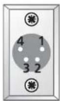
Output Connector
Viewed From OUTSIDE The PSU
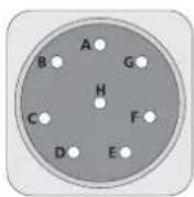
Output Connector
Viewed From OUTSIDE The PSU

Output Connector
Viewed From OUTSIDE The PSU
Output Voltage Adjustments

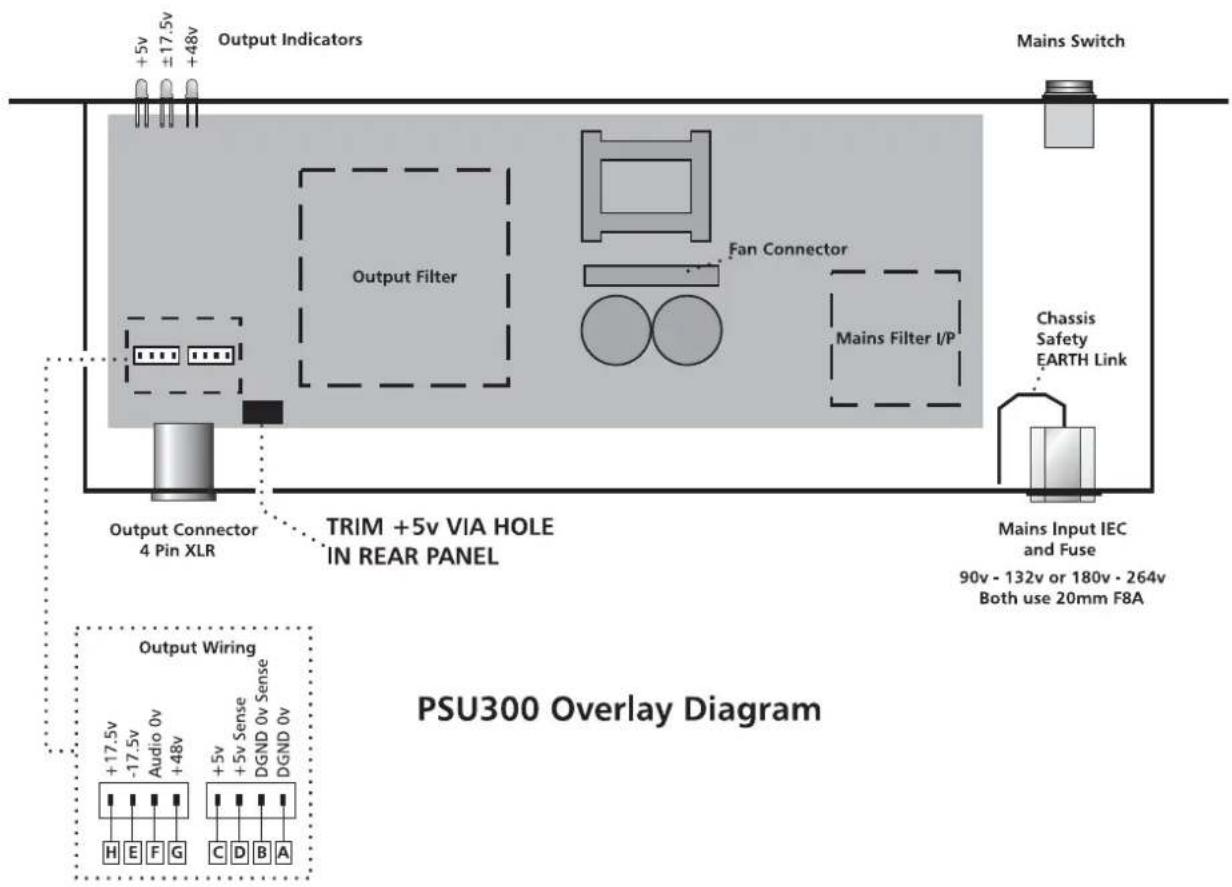
The voltage adjustment presets are adjusted during manufacture and should not need resetting unless major repairs have been done to the units. The adjustment trimmers for each PSU are shown in the following diagrams. Any adjustment should be checked with the unit on load.

Note: Only an insulated trimmer tool should be used before making any adjustment.
Note: There are no user trimmable controls on the PSU 300 except for a for a voltage adjustment on the 5v output. This is accessed through a small hole in the rear panel.
Note: The BB100 does not use the 5V rail on the PSU 300.
Output Voltage Adjustments - MPS 5

Output Voltage Adjustments - MPS 20

Connectors
4
Contents
Connections. 4 - 3
Back Panel Layout 4 Group 4-4
Back Panel Layout 8 Group 4-5
Fader Starts / Monitor Logic / Remote Mutes ..... 4-6
56 Way I/O EDAC Connections 4-7
Power Supplies 4 - 8
Connections
All the main audio inputs and outputs are located on the back panel of the console. The Mic inputs are balanced and are via 3 pin female XLR connectors.
Inputs and Outputs are electronically balanced excluding the send, which is Ground Compensated. The headphone output is located at the front of the console and is via a stereo 1/4 inch jack socket.
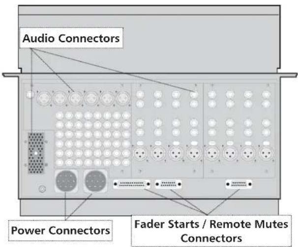
Rear view of console (14 Position)
Wiring Conventions

Soundcraft uses the standard XLR wiring convention on all consoles. Not all equipment uses this convention so check your wiring to prevent any phase reversals. See table below for wiring convention.
| Pin XLR | |
| Pin 2 HIGH (HOT) + | |
| Pin 3 LOW (COLD) - | |
| Pin 1 SCREEN (GROUND) |
| Pin 1⁄4 Inch Jack Plug | |
| Tip HIGH (HOT) + | |
| Ring LOW (COLD) - | |
| Screen SCREEN (GROUND) |
Back Panel Layout 4 Group
BB100 4 Group Back Panel
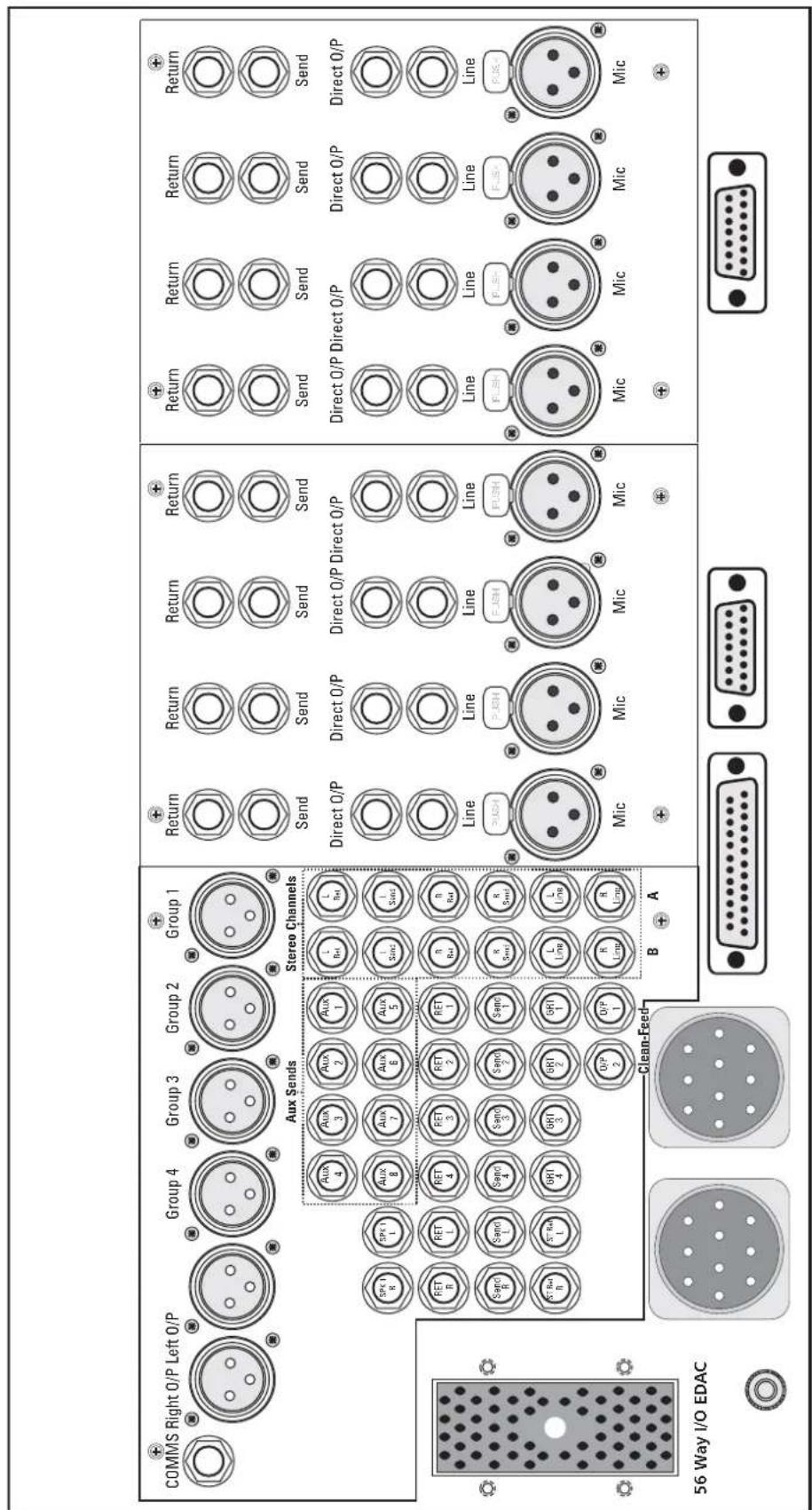
Fader Starts
Remote Mutes
15 Way Female D Type
Fader Starts
Remote Mutes
15 Way Female D Type
Fader Starts
Monitor Logic
Power Input Connectors
EARTH Post
Back Panel Layout 8 Group
BB100 8 Group Back Panel
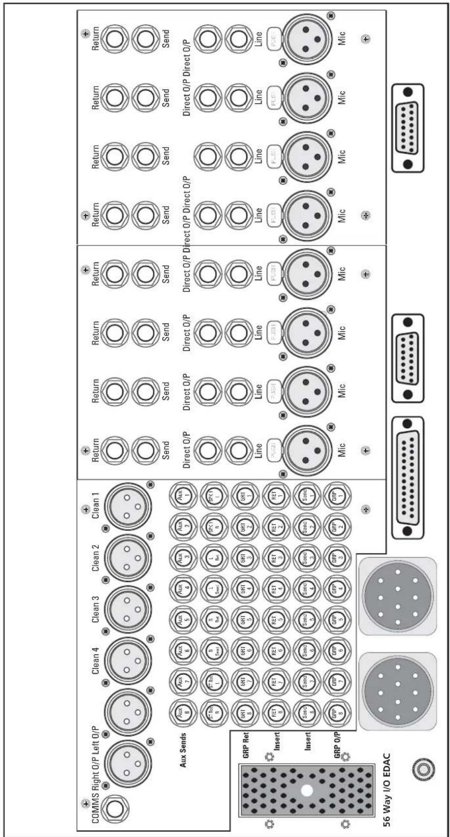
Fader Starts Remote Mutes 15 Way Female D Type
Fader Starts Fader Starts Monitor Logic Remote Mutes 25 Way Female D Type 15 Way Female D Type
Power Input Connectors
EARTH Post
Fader Starts / Monitor Logic / Remote Mutes
Fader Start
The Fader Start switch allows tape recorders or similar equipment to be remote started. The connection is designed for use with 5 volt (TTL/CMOS type) logic systems and is controlled by an active low. Internal module jumpers select whether or not the TALLY Led can be controlled internally or externally. The TALLY Led when set to external is controlled by applying an active low to a pin on the D Type connector located on the rear panel. If the internal Tally as been selected then the LED is directly driven of the fader start system.
Monitor Logic / Remote Mutes
The Monitor Logic and the Remote Mutes are controlled by applying an active low to a pin on the D Type connectors located on the rear panel.
Fader Starts
Monitor Logic
25 Way Female D Type

Viewed From OUTSIDE The Console
Note: All controls are activated by an active LOW
Pin 1: Chassis Ground
Pin 2: User Switch O/P
Pin 3: External Talkback Control
Pin 4: Group Mute Control (GRP3) (Option)
Pin 5: Group Mute Control (GRP1) (Option)
Pin 6: Remote Mute Control (Pos 13)
Pin 7: Remote Mute Control (Pos 11)
Pin 8: Remote Mute Control (Pos 9)
Pin 9: External Fader Start (Pos 12)
Pin 10: External Fader Start (Pos 11)
Pin 11: External Fader Start (Pos 10)
Pin 12: External Fader Start (Pos 9)
Pin 13: A Ground
Pin 14: User Tally Control
Pin 15: Remote User In
Pin 16: Group Mute Control (GRP 4) (Option):
Pin 17: Group Mute Control (GRP 2) (Option)
Pin 18: Studio Remote Cut
Pin 19: Remote Mute Control 12
Pin 20: Remote Mute Control 10
Pin 21: Remote External Tally Control 12
Pin 22: Remote External Tally Control 11
Pin 23: Remote External Tally Control 10
Pin 24: Remote External Tally Control 9
Pin 25: Analogue Ground
Fader Starts
Remote Mutes
15 Way Female D Type

Viewed From OUTSIDE The Console
Note: All controls are activated by an active LOW
Pin 1: Chassis Ground
Pin 2: Remote Channel Mute (Pos 3)
Pin 3: Remote Channel Mute (Pos 1)
Pin 4: External Fader Start (Pos 4)
Pin 5: External Fader Start (Pos 3)
Pin 6: External Fader Start (Pos 2)
Pin 7: External Fader Start (Pos 1)
Pin 8: A Ground
Pin 9: Remote Channel Mute (Pos 4)
Pin 10: Remote Channel Mute (Pos 2)
Pin 11: Remote External Tally Control (Pos 4)
Pin 12: Remote External Tally Control (Pos 3)
Pin 13: Remote External Tally Control (Pos 2)
Pin 14: Remote External Tally Control (Pos 1)
Pin 15: A Ground
56 Way I/O EDAC Connections
Input and Output Connections
I/O connections are supplied via a 56 way EDAC located on the rear panel.
56 Way I/O EDAC

| A Chassis Ground | R Tape 3R-Hi | e Tape 1L-Hi | v Monitor SPK2R-Lo | KK Chassis Ground |
| B Tape 4R-Hi | S Tape 3R-Lo | f PPM-R | W Chassis Ground | LL Monitor RET2-Hi |
| C Tape 4R-Lo | T Chassis Ground | h Tape 1L-Lo | X Monitor RET4-Hi | MM Monitor RET2-Lo |
| D Chassis Ground | U Tape 2R-Hi | j A Ground | y Monitor RET4-Lo | NN Chassis Ground |
| E PPM-L | V Tape 2R-Lo | k Chassis Ground | z Chassis Ground | |
| F A Ground | W Tape 2L-Hi | l Chassis Ground | AA Monitor SPK2L-Hi | |
| H Chassis Ground | X Tape 2L-Lo | m Chassis Ground | BB Monitor SPK2L-Lo | |
| J Tape 4L-Hi | Y Tape 1R-Hi | n Chassis Ground | CC Chassis Ground | |
| K Tape 4L-Lo | Z Tape 1R-Lo | p SPK2R-Hi | DD Monitor RET3-Hi | |
| L Chassis Ground | a Chassis Ground | r SPK2R-Lo | EE Monitor RET3-Lo | |
| M Tape 3L-Hi | b Chassis Ground | s SPK2L-Hi | FF Chassis Ground | |
| N Tape 3L-Lo | c Chassis Ground | t SPK2L-Lo | HH Monitor RET1-Hi | |
| P Chassis Ground | d Chassis Ground | u Monitor SPK2R-Hi | JJ Monitor RET1-Lo |
Viewed From OUTSIDE The Console
Power Supplies
DC Input Connector Pin Out - PSU300

Viewed From OUTSIDE The Console
DC Input Connector Pin Out - MPS5
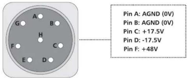
Viewed From OUTSIDE The Console
DC Input Connector Pin Out - MPS20
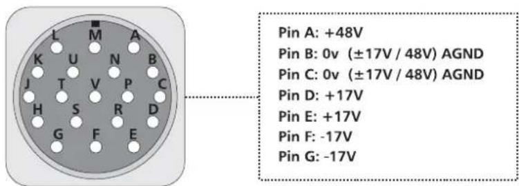
Viewed From OUTSIDE The Console
Modules
5
Contents
LBI The Mono Input Module. 5-3
LBS The Stereo Input Module ..... 5-5
LB2 The Dual Group Module 5-7
LB6 The Auxiliary Master Module ..... 5-9
LB4 The Stereo Master Module ..... 5-10
Metering 5-11
BB100 Jumper and Switch Options. 5-12
14 Position Motherboard 5-12
LBI Mono Input Module Options 5-15
LBS Stereo Input Module Options 5-17
LB2 Dual Group Module Options 5-19
LB4 Master Module Options 5-21
LB6 Aux Master Comms Module Options 5-24

LBIMonoInputModule
TheLBIMonolInputisprovidedwithXLRand/4jackconnectors,eitherof whichmaybeusedforanylevelofinputsignal.
The channel is provided with insert points using a Ground Compensated Send and a Balanced Return at an nominal level of +4 dBulocated on therear panel.
I. The48Vswitchapplies48vphantompowertotheMicInputXLR.
Note: Undernocircumstancespressthe48vswitchifanunbalanced sourceisconnectedtotheXLR.
2. The Pad attenuates the MicInput by -15 dBu and allow high level signal to be used. Maximum input level + 7 dBu.
3. TheLineswitchselectstheLineAmpinsteadoftheMicAmp.
4. The (Phase) switch reverse the phase of the Mic Input or the Line Input. Theswitch should normally be released.
5. The Gain control adjuststhesensitivity of both the XLRandjack inputs. The Micrangeis + 10dButo + 70dBu. The Linerangeis ± 20dBu.
Equaliser
-
The EQ section has four bands. The HF and LF sections have an shelving response with selectable frequencies. The two MID sections have a bell response at a variable frequency.
-
TheHFcontrolgives I8dBofcutorboostswitchableatfrequencies 6kHzor I2kHz.
- TheLFcontrolgives18dBofcutorboost. Thefrequencyswitchselects between40Hz and 80Hz. Using the X3 switch multiplies these selected frequencies by three giving a selection of 120Hz or 240Hz.
- TheHMFcutandboostcontrolgivesarangeof±14dB.TheHMF frequencycontrolgivesavariablefrequencyrangeof300Hzto6kHz. UsingtheX3switchmultipliestheselectedfrequenciesby3givinga rangeof900Hzto18kHz.UsingtheQswitchselectseither0.7or 1.3QFactor.
-
TheLMFcutandboostcontrolgivesarangeof ± 14dB. TheLMF frequencycontrolgivesavariablefrequencyrangeof40Hz to 800Hz. Using the X3 switch multiplies the selected frequencies by three giving arangeof 120Hz to 2.4kHz. Using the Qswitch select either 0.7 or 1.3QFactor.
-
The HP switch inserts a HI-PASS filter into the signal path. The -3dB point is fixed at 80 Hz at 18 dB per octave.
- The EQIN switch insertstheequaliser into the signal path.

AuxiliarySends
-
SignalissenttotheAux1-8busesviatheeightLEVELcontrols. All the Auxshaveunitygainwhenthecontrolsarefullyclockwiseandareswitched preorpostinpairsbythePREswitches.
-
Aux s l & 2 h a s a n internalswitchoptiontoconfiguretheAuxtoaStereo level/panarrangement.
Routing
II. The Pancontrol feedsthesignal to the Stereomix and the groups. Panning left pan stothe odd groups and Stereole left, panning right pan sto the even groups and Stereoright. In the centre position there is a drop of 3 dB.
12. TheGroupDisableswitchwhenselecteddisablespanningacrossthe groups.
13. The Muteswitchcutsoffalloutputfromthechannelandutilisesasoft
muteforclickfreeswitching.
14. The PFL switch provides a preface design to the monitors speakers replacing these selected sources. There is an internal switched option, which allows the PFL to become after Fadelisten.
15. The Faderisthemainlevelcontrolforthechannel.lthas l0dBofgainat thetopoftravel.
16. The Group switches assign the signal in pairwise group buses. The source signal can be preor post pan as selected by the Group Disable switch. Groups are available only if the appropriate amount of group modules is fitted.
17. The StereoswitchassignsthesignaltotheStereobus.
18. ThefoursegmentPFLmeterdisplaysthechannelpre-fadelevel. ThemetermonitorsthesignalpreandpostEQsimultaneously. TheO/Lledilluminateswhenthesignalreaches + 18dB.
19.AGroundCompensatedDirectOutputisprovidedwhichisnormally feedfromthepostfadesignal(FactoryPre-set)butcanbeselectedtobeprefade/postmuteorpreEQbyinternaljumpers. TheDirectOutputsarefedtojacksontherearpanel.

LBSStereoInputModule
TheLBSStereoInputModuleisprovidedwith1/4jackconnectorsontherear panel.
ThechannelisprovidedwithStereoinsertpointsusingGroundCompensatedSendsandBalancedReturnsatanominallevelof+4dBulocatedontherear panel.Theinsertpointshaveaninternaloptiontomovethepointspostpan.
I. The MonoLeftswitchappliesthelefthandsignaltotheleftandrightofthe module.
2. The MonoRightswitchappliestherighthandsignaltotheleftandright handsideofthemodule.Ifbothswitchesarepressedtogethertheleftand rightsignalsappearonbothsidesofthemodule@-6dB.
3. The (Phase) switch reverse the phase of the right hands sides, signal only. Theswitch should normally bereleased.
4. The Gain controls adjust the sensitivity of both the left and right jack inputs. The Linerangeis ± 20 dBu.
Equaliser
- The EQsection has three bands. The HF and LF sections have an shelving response with selectable frequencies. The MID sections have a bell response at a variable frequency.
• TheHFcontrolgives18dBofcutorboostswitchableatfrequencies 6kHzor12kHz.
- TheLFcontrolgives18dBofcutorboost. Thefrequencyswitchselects between40Hz and 80Hz. Using the X3 switch multiplies these selected frequencies by three giving a selection of 120Hz or 240Hz.
- TheMFcutandboostcontrolgivesarangeof±14dB. TheHMF frequencycontrolgivesavariablefrequencyrangeof80Hzto5kHz. UsingtheX3switchmultipliesetheselectedfrequenciesby3givinga rangeof240Hzto15kHz. UsingtheQswitchselectseither0.7or1.3 QFactor.
-
The HP switchinsertsaHI-PASSfilterintothesignalpath. The -3dBpoint is fixed at 80Hz at 18dB per octave.
-
The EQ switch insertstheequaliser into the signal path.

AuxiliarySends
Note: The preand postsignals are the sum of the left and right signals except A u x I & 2 which has an internal switch option to configure it to a Stereo level/pan arrangement i.e. Aux I will be fed by the left only and Aux 2 will be fed from the right only.
- SignalissenttotheAux I -8busesviatheeightLEVELcontrols. AlltheAuxshaveunitygainwhenthecontrolsarefullyclockwise andareswitchedpreorpostinpairsbythePREswitches.
Routing
-
The PancontrolfeedsthesignaltotheStereomixandthegroups. PanningleftpanstotheoddgroupsandStereoleft, panningrightpansto theevengroupsandStereoright. In the centreposition there is a drop of -3dB.
-
The Stereo Muteswitchcutsoffalloutputfromthechannelandutilises asoftmuteforclickfreeswitching.
II. The PFL switch provides a preface designaltothemonitors speakers replacing these selected source. There is an internal switched option, which allows the PFL to become a postfadesignal-thissignalisaderived postpan.
-
The Stereo Faderisthemainlevelcontrolforthechannel.Ithas I0dBof gainatthetopoftravel.
-
The Group switches assign the signal in pairwise to the group buses. Thesources signals all ways postpan. Groups are available only if the appropriate amount of group modules are fitted.
-
The StereoswitchassignsthesignaltotheStereobus.
-
ThefoursegmentPFLmeterdisplaysthechannelpre-fadelevel. Themetermonitorsthesignalpremute,leftandrightsimultaneously. TheO/Lledilluminateswhenthesignalreaches + 18dB.

LB2DualGroupModule
TheDualGroupModuleisprovidedwithXLRsona4groupconsoleand1/4jacksona8groupconsole,insertsendandreturns.Cleanfeedoutputs areprovidedonXLRsonan8groupconsoleandjacksona4groupconsole.
I. SignalissenttoAux I -4busesviathefourlevelcontrols. TheAuxshave unitygainwhenthecontrolsarefullyclockwise. Thesourcesignalisfed frompreorpostgroupfaders. Thepreorpostswitchoperatesonallfour Auxs.
-
The other four Auxiliaries are fed from the other group (Right) fader. Each Dual Group module contains one clean-feed master therefore the amount of clean-feed buses is dependent on the amount of Dual Group modules fitted.
-
The Level control adjusts the level of the balanced Clean-Feed output which is fed from these selected clean-feed input module. Jumpers make the clean-feed bus selection of which positions are used to source on the 14 position motherboard. Therefore if the signal is inserted into the first of the input modules (clean-feed I) it will then be removed from the clean-feed output on the group module.
-
The Talk Enable switch provides signal from the Comms system to be fed to the clean-feed outputs when the Commssystem is activated.
-
The clean-feed Muteswitch cut soff the signal to the clean-feed outputs.
-
The clean-feed AFL switch provides the post-level signal to the monitoring speakers replacing these selected sources.
-
Signal is sent to the Aux 1 & 2 bus via the Aux Level control (optionallyAux 3 & 4 usingtheinternaljumpers).AlltheAuxshaveunity gainwhenthecontrolsarefullyclockwiseandareswitchedpreorpostin pairsbythePREswitches.ThesourceisfedfromtheGroupReturn.
-
The StereoReturnLevelcontroladjuststhelevelofthereturnsignal. Gainof+10dBofgainisprovidedwhenthecontrolisfullyclockwise.
-
The ST/MixGroup switch determines whether the output can be sent to the StereoBus or the associated pair of groups.
-
The PancontrolfeedsthesignaltotheStereomixorthegroups. Inthecentrethereisadropof-3dB.
-
The Return Mute switch cuts of the signal from the Stereo bus or the groupbus.AlsomutesthePFLandauxpreandpost.
-
The Return PFL switch provides Pre Fade signal to the monitor speakers replacing these selected source.
-
TheSTAAssignswitchassignsthesignaltotheStereobus. Thesourcesignalisfromthegroupoutputfader.
-
The PancontrolfeedsthesignaltotheStereobusandtotheStereoAFL bus. In the centrethereisadropof-3dB.
-
The Muteswitchcutsoffalloutputfromthechannelandutilisesasoft muteforclickfreeswitching.

- The AFL switch provides a postfadesignal to the monitors speakers replacing these selected source.
- The STAssignswitchassignsthesignaltotheStereobus.
- The PancontrolfeedsthesignaltotheStereobusandtotheStereoAFL bus. In the centrethereisadropof-3dB.
- The Muteswitchcutsoffalloutputfromthechannelandutilisesasoft muteforclickfreeswitching.
- The AFL switch provides a postfadesignal to the monitors speakers replacing these selected source.
- The FadersarethemainlevelcontrolfortheDualGroupmodule. They have 10dBofgainatthetopoftravel.
Metering
The group output meters signal is derived postfade and supply the group meter in the meter hood. A trimmer supply for calibration. (Factory Preset).
Theclean-feednulltrimisusedtooptimisecleanfeedattenuation. (FactoryPreset).
Each Dual Group has a pre-fade insert point (located on the back panel) using a Ground Compensated Send and Balanced Return at an nominal level of -2 dBu.

LB6AuxiliaryMasterModule
TheAuxMastermoduleisprovidedwithjackconnectorsfortheoutputs
Comms
TheTalkbacksystemprovidescommunicationtotheGroupsandAuxoutputs andspeakeroutputs.
- The3pinXLRconnectorprovidesabalancedtalkbackinputforalocal microphoneorgooseneckmic. Thesensitivityofthemicinputisvariable between +10dBuand +70dBu.
- The Talk switch can be momentary or latching depending on the length of timepressed. Destinationofthetalkbacksourcesareselectedby4 switches.Slateassignsthecommssystemtothegroupbuses1-8and/or theStereoBus.Aux5-6assignsthecommssystemtoaux5,6,7,8. Aux1-4assignsthecommssystemtoaux1,2,3,4.Speakerassignsthe commssystemtoMonitor2speakeroutputsand/orthecommsoutput connectorlocatedonthebackpanel.
- A User switch at the top of the module can activate ON-AIR mode. When theOn-Airmodeisenablednoaccesstotheslatebusisavailablefromboth thecommsortheoscillator.TheoscillatorisdisabledfromtheAuxbuses andthecommsoutputbuttheCommsSystemstillhasaccess.TheUser switchautomaticallymutestheMon2speakers.
- The Auxiliary Master level controlset the output level of the Aux send mixes. With the controls fully clockwise 10 dB of gain is provided. The Aux outputs are fully balanced and terminate via jack connectors on therear panel.
- The AFL switch provides a postfadesignal to the monitors speakers replacing these selected source.
- The Muteswitch cut soffall output from the Aux masters
Oscillator
-
A Trimmer is provided for the calibration of the oscillator. (Factory Preset@ +4dB).
-
Athreefrequencyoscillatorisselectedbytwoswitches. The 1kHzswitch provides a kHzsinewave. The 10kHzswitchprovides a 10kHzsinewave. Pressingbothswitchesprovides 100Hz. When not in use both buttons should be released to prevent leakage from the oscillator onto the console outputs. The oscillator utilises the same four assignment switches as the commssystem to enable access to the same output, aux sends and speaker outputs.
9.AHeadphoneoutputisprovidedwhichcanbefedfromtheControlRoom MonitorsoroptionallyMon2,selectedbyinternaljumpers.Thephones outputsocketisa¼inchjack.Itshouldnotbeusedwithheadphonesof lessthan200ohmsimpedance.Asecondheadphonesjackisprovidedon theconsolechassis.

LB4StereoMasterModule
-
Signal is sent to the Aux 1-4 buses via the four Level/Pan controls. TheupperfouraresourcedfromtheleftStereobusandthelowerfour fromtherightStereobus.Theyareswitchedpreorpostingroupsoffour bythePREswitches.InternaljumperscanconfiguretheAuxcontrolsas alevel/leveloption. A furtheroptionallowsthesourcesignaltobederivedfromthemonitor returninputsinsteadoftheStereobus,viainternaljumpers. TheAuxsendscanalternativelybeClean-Feedsendsagainviainternal jumpers.
-
TheSTReturnLevelcontroladjuststhelevelofthereturnsignal. Thelevelrangeis-20dBto+10dB.
-
The MuteswitchcutsoffalloutputfromtheReturntotheStereobus.
-
The PFL switch provides a preface designaltothemonitors speakers replacing these selected source.
-
The VU/PEAK switch provides switching between VU and PEAK characteristics for the LED bargraphmeters. The VU settings show the average level of the program. The PEAK setting will show transients levels within the program.
-
The PFL/AFLLevelcontroladjuststhelevelofthesolobustothemonitor speakers. The level control is unity gain when fully clockwise. The PFL/AFL Led indicates an activesolosystem.
-
The Monitor 2 Level control adjusts the level of the Monitor 2 speakers or Headphone output. There is a power on mute for click freepowerups.
8.STMix/CRMONswitch.WhentheswitchisreleasedtheStereoBuswill befedtotheMonitor2output.Whentheswitchisdepressed (nowCRMON)Monitor2willfollowtheCRMONsourceselection.
-
STReturnswitch. Whentheswitchisdepresseditoverridesthe STMix/CRMONswitchmakingtheSTReturnthesourcetotheMON2 output.
-
There are four 2 Track Return inputs, electronically balanced, which are fedfroma56wayEDACconnectorontherearpanel. Tape I has an internaljumperselection, which allow sthesensitivity of the input to beset at +4dBuor-6dBu. All other monitor inputs operate at an nominal level of +4dBu.
-
TheSTReturnswitchselectstheSTReturnsignaltobefedtotheMonitor outputspeakers.InternaljumperscanreconfiguretheSTReturnswitchtoalternativelysourcetheAuxsends.
-
The STMix switch selects the Stereo Bustobefed to the Monitor outputs.
-
The Level control adjust the level to the Monitor outputs (Control Room) and/or headphone outputs.
-
The SPK2 switch provides the ST monitor output to be fed to an alternative pair of speakers. Monitor outputs are provided with a Ground Compensated output at an nominal level of +4dB to a 1/4-inch jack on the rear panel. SPK2 outputs are provided on a 56 way EDAC on therear panel.

- The MuteswitchcutsoffalloutputfromtheconsoletotheMonitor speakers.
- The FadersarethemainlevelcontrolfortheStereoMaster. Theyhave I0dBofgainatthetopoftravel.
- The Mix Muteswitch cut soff the output from the Stereo Bus.
Metering
Levelindicationismonitoredby28segmentLEDbargraphmetersandVU meters,whicharelocatedinthemeterhood.ThemetersreadGroupOutput, Stereo Mix or 2 Track Returns or the PFL/AFL bus.
ThebargraphmeterscanbesettoreadVUorPEAKbytheswitchonthe StereoMastermoduleLB4.
Themetersourceselectswitch, CRMon/PFL, enable the VU metersto monitor the Control Room outputs or the PFL bus.
MetertrimsareprovidedforthefineadjustmentoftheVUmeters. (FactoryPre-set).
BB100JumperandSwitchOptions
I4PositionMotherboard-GL1850
Jumpers PI to P10 are the Cleanfeed options and will be set depending on the operationandconfigurationoftheconsole.
![graph TD A["14 POSITION MOTHERBOARD CLIMB"] --> B["14 POSITION MOTHERBOARD"] B --> C["P1"] C --> D["P5"] D --> E["P6"] E --> F["P7"] F --> G["P8"] G --> H["P9"] H --> I["P10"] I --> J["14 POSITION MOTHERBOARD"] K["INPUT"] --> L["P11"] L --> M["P12"] N["LW/2V"] --> O["14 POSITION MOTHERBOARD"] P["INL…](/content/2026/06/1362747/images/447f6e02d20dae24a54315b70ca58015c249071719cc472b200980379d90f6a2.jpg)
PI/P5
CleanfeedPosition5
Toenablethemoduleinposition5tobethecleanfeed inputlinkpins 1 - 2. ThiscanonlybeappliedtoaMonochannelortheright inputforaStereochannel.
Note:-P5shouldbeinthedisabledpositionifaMono channelisfitted.IfaStereochannelisfittedJumperP5will besetasPIandappliestotheleftinputfortheStereo channel.


P2/P6
Cleanfeed Position 6
To enable the module in position 6 to be the cleanfeed input link pins 1 - 2. This can only be applied to a Mono channel or the right input for a Stereo channel.
Note: - P6 should be in the disabled position if a Mono channel is fitted. If a Stereo channel is fitted Jumper P6 will be set as P2 and applies to the left input for the Stereo channel.


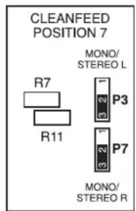
P3/P7
Cleanfeed Position 7
To enable the module in position 7 to be the cleanfeed input link pins 1 - 2. This can only be applied to a Mono channel or the right input for a Stereo channel.
Note: - P7 should be in the disabled position if a Mono channel is fitted. If a Stereo channel is fitted Jumper P7 will be set as P3 and applies to the left input for the Stereo channel.
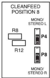
P4/P8
Cleanfeed Position 8
To enable the module in position 8 to be the cleanfeed input link pins 1 - 2. This can only be applied to a Mono channel or the right input for a Stereo channel.
Note: - P8 should be in the disabled position if a Mono channel is fitted. If a Stereo channel is fitted Jumper P8 will be set as P4 and applies to the left input for the Stereo channel.
P9
Cleanfeed position 9
If position 9 has a Group module fitted P9 must be in the disabled position. If a Stereo module is fitted and it is to be used as a Cleanfeed input P9 has to be enabled. To enable link pins 1 – 2.

PIO
Cleanfeed position 10
If position 10 has a Group module fitted P10 must be in the disabled position.
If a Stereo module is fitted and it is to be used as a Cleanfeed input P10 has to be enabled.
To enable link pins 1 - 2.


Jumpers P11 and P12 are the Virtual Earth Disable options and will be set depending on the operation and configuration of the console.
PII
Virtual Earth Disable options
Cleanfeed Jumpers. In an eight group console no jumpers are fitted. In a four group console jumpers are fitted to disable the unused Cleanfeed buses 3 and 4. To disable link pins 5 - 6 and 7 - 8.
If the Cleanfeed buses 3 and 4 are unused link pins 1 - 2 and 3 - 4.
When Group modules 5 to 8 are omitted the relevant virtual earth buses are grounded. To disable the Groups 5 to 8 link pins 9 – 10, 11 – 12, 13 – 14 and 15 – 16.

PI2
When Group modules 5 to 8 are omitted the relevant virtual earth buses are grounded. To disable the Groups 5 to 8, link pins 1 - 2, 3 - 4, 5 - 6 and 7 - 8.
LBIMonoInputModule JumperandSwitchOptions-GLI864

PI
SignalisationSelect
Toenabletheremotemutefacilityonthechannel,linkpins 4-6(FactoryPre-set).Applyinganactivelowtoapinon the l5wayDTypeconnectorcontrolstheremotemute. Thisislocatedonthebackpanel.Todisabletheremote muteandenabletheoptionalVCA,linkpins 2-4. ToenabletheexternalTallyindicator,linkpins 3-5.
Note:-TheTallyLEDindicatorwhensettoexternalis controlledbyapplyinganactivelowtoapinonthe15way DTypeconnector, Thisislocatedonthebackpanel. IftheinternalTallyhasbeenselectedbylinkingpins 1 - 3 (FactoryPre-set)theLEDisdrivendirectlyoffthefaderstartsystem.

P2
DirectSource
Givestheoptionofselectingthesourcesignalforthe Directoutput. ToselectthesourcesignaltobePreEq,link pins 1 - 2. To selectthesourcesignaltobePostFader,link pins 3 - 4 (FactoryPre-set). Toselectthesourcesignalto bePreFader,PostMutelinkpins 5 - 6.

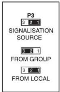
P3.
SignalisationSource.
ToenabletheLocalmodelinkpins 1 - 2 (FactoryPre-set). ToenabletheGroup/Mastermodelinkpins 2 - 3 . Localmode,iftheMic/LineswitchisselectedtoLineand thechannelfaderisopen,anactivelowissenttothe15 wayDTypeconnector. Thisislocatedonthebackpanel. IftheMicisselectedandthefaderisopentheStudio outputswillmute.Nosignalissenttothebackpanel. TheGroup/Mastermodeoperationisasabove,excepta GrouponMasterfaderhastobeopentotriggerthesignal signalisation.
S31
PFL / AFL Select Switch.
When the switch is out (Factory Pre-set), pre fade listen is sent to the Monitor outputs when any SOLO switch is pressed. When the switch is pressed in, stereo after fade listen is sent to the Monitor outputs when any SOLO switch is pressed.

S32.
Aux I & 2 Mono Stereo Switch.
When the switch is out, Aux 1 & 2 acts as a level / level arrangement (Factory Pre-set). When the switch is pressed in, Aux 1 & 2 are converted to a level / pan arrangement.

LBSStereoInputModule JumperandSwitchOptions-GL1865

PI
SignalisationSelect
Toenabletheremotemutefacility, linkpins 4 – 6 (FactoryPre-set). Applyinganactivelowtoapinonthe 25/15wayDTypeconnectorcontrolstheremotemute. Thisislocatedonthebackpanel. (25wayforGroupposition, 15wayforInputposition). TodisabletheremotemuteandenabletheoptionalVCA controllinkpins 2 – 4. Toenabletheexternaltallyindicator, linkpins 3 – 5.
Note:-TheTallyLEDindicatorwhensettoexternal,is controlledbyapplyinganactivelowtoapinonthe25/15 wayDTypeconnector. Thisislocatedonthebackpanel (25wayforGroupposition, 15wayforInputposition). IftheinternalTallyhasbeenselectedbylinkingpins 1 - 3 (FactoryPre-set), theLEDisdrivendirectlyoffthefaderstartsystem.

P2.
StereoInsertPositionSelect.
ToselectstereoinsertpositiontobePostEq,linkpins 1-2,3-5,4-6,7-8,9-11 and 10-12 (FactoryPre-set). ToselectthestereoinsertpositiontobePostFaderand PostPan,linkpins 1-3,2-4,5-6,7-9,8-10 and 11-12.

P3
SignalisationSource
ToenabletheLocalmode, linkpins 1 - 2 (FactoryPre-set). To enable the Group / Master mode, link pins 2 - 3. Local mode, if the channelfader is open an a activ e low is sent to the 15 way DType connector. This is located on the back panel. The Group/Master mode operation is as above except a Groupon Master fader hast o be opent o trigger the signals signalisation.

S27
PFL / AFL Select Switch
When the switch is out (Factory Pre-set), stereo pre fade listen is sent to the Monitor outputs when any SOLO switch is pressed.
When the switch is pressed in, stereo after fade listen is sent to the Monitor outputs when any SOLO switch is pressed.

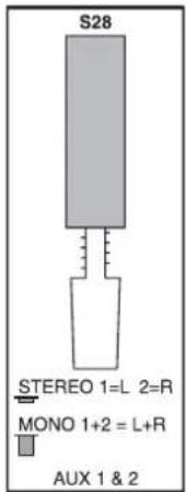
S28
A u x l & 2 Mono Stereo Switch
When the switch is out, Aux 1 & 2 is fed by a mono mix of left and right (Factory Pre-set).
When the switch is pressed in, Aux 1 & 2 are sourced in stereo so Aux 1 is left only and Aux 2 is right only.
LB2DualGroupModule JumperandSwitchOptions-JP1866
![graph TD A["P1"] --> B["S16"] C["P2"] --> B B --> D["P4"] B --> E["P5"] B --> F["P6"] D --> G["J3"] E --> H["J4"] F --> I["J5"] G --> J["DUAL GROUP MODULE JP 1866"] H --> J I --> J J --> K["J7"]](/content/2026/06/1362747/images/e69dd914635831712ace067b36aef5ecd143d5bfa082ec143bb1f02131edf5c4.jpg)
PI
CleanfeedOffGroupSource
ToroutethesignalfromtheAuxPre/Postswitchchandsend ittotheCleanfeedoutput,linkpins 3 - 5 and 4 - 6 . E.g.If themoduleisGroups I & 2 , G r o u p s I & 2 willbesentto CleanfeedI.Todisablesthefunction,linkpins I - 3 and 2 - 4 (FactoryPre-set).

P2
CleanfeedJumper
Linkingpins 3 – 5 (FactoryPre-set) enable the chosen Cleanfeed bust be connected to the Cleanfeed mixamp. Linkingpins 1 – 3 disconnects Cleanfeed bus from the Cleanfeed mixamp. Linkingpins 4 – 6 (FactoryPre-set) sends the Cleanfeed cancellations signal to the Cleanfeed mixamp. This signal is out of phase and will cancel out any identical signal on these selected Cleanfeed bus. Linkingpins 2 – 4 disable the Cleanfeed cancellations signal.

P4
CleanfeedBusSelection
ThisallowsyoutoselecttheappropriateCleanfeedbuses. ToconnectCleanfeedbus1tothemoduleinthefirst groupposition,linkpins 7 - 8 .
ToconnectCleanfeedbus2tothemoduleinthesecond groupposition;linkpins 5 - 6 .
ToconnectCleanfeedbus3tothemoduleinthethird groupposition,linkpins 3 - 4 .
ToconnectCleanfeedbus4tothemoduleinthefourth grouppositionlinkpins 1 - 2 .

Note:-InafourGroupconsoleCleanfeedbuses3and4 will be used for Cleanfeed outputs 1 & 2. Only link one bus per modules.
P5
Return Aux Send Bus Select
To select Aux buses 1 & 2, link pins 4 - 6 and 3 - 5 (Factory Pre-set).
To select Aux buses 3 & 4, link pins 1 - 3 and 2 - 4.

P6
Group Bus Select
These jumpers should be set for the appropriate Group buses.
To select Groups 1 & 2, link pins 1 - 2 and 3 - 4.
To select Groups 3 & 4, link pins 5 - 6 and 7 - 8.
To select Groups 5 & 6, link pins 9 - 10 and 11 - 12.
To select Groups 7 & 8, link pins 13 - 14 and 15 - 16.
Note: - Only link one pair of buses per module.

P7
Remote Mute / VCA Control Select
To enable the remote mute facility on the Group module, link pins 1 - 2 (Factory Pre-set).
Applying an active low to a pin on the 25 way D Type connector controls the remote mute. This is located on the back panel. To disables the remote mute and enables the optional VCA control, link pins 2 – 3.

P8
Signalisation Select
To disable the Group fader start switch; link pins 1 - 2 (Factory Pre-set).
To enable the Group fader start switch; link pins 2 - 3.

S16
Group Sends Aux
When the switch is pressed in, the Group sends are Aux sends 1 to 4 (Factory Pre-set).
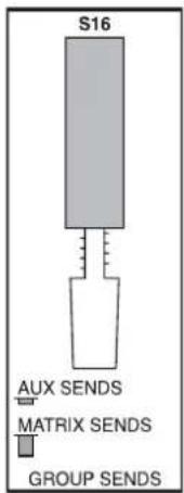
LB4MasterModule JumperandSwitchOptions-GL1867
![graph TD P1["Sensor P1"] --> P2["Sensor P2"] P2 --> P3["Sensor P3"] P3 --> P4["Sensor P4"] P4 --> P5["Sensor P5"] P5 --> P6["Sensor P6"] P8["Sensor P8"] --> P9["Sensor P9"] P9 --> P10["Sensor P10"] P10 --> P11["Stereo Monitor Module"] P11 --> P12["Stereo Monitor Module"] P12 --> P13["Stereo Monitor…](/content/2026/06/1362747/images/2ef1b28bdf6e3e3e615c9b15cfefe34effbaae85502596a4e1317511b7b3d9da.jpg)
P1,P2,P8,andP9
MonitorAuxSendMono/StereoSelect
StereobusleftandrighthasfoursetsofAuxsends.
Thesecanbeconfiguredasastereo/levelpan arrangementormonolevel/levelarrangementinpairs.
P9operatesofftheStereobusleftforAux1and2.
P8operatesofftheStereobusleftforAux3and4.
P2operatesofftheStereobusrightforAux1and2.
PI operatesofftheStereobusrightforAux3and4.
ToconfigureasStereo.(FactoryPre-set),linkpins 3 - 5, 4 - 6, 9 - 11 and 10 - 12.
ToconfigureasMono,linkpins 1-3,2-4,7-9 and 8-10.

P3andP5
Auxsends/ReturnLevelDestinationSelect
ConfiguresthedestinationoftheAuxlevelcontrols.
ToselectAuxbuses1,2,3,and4,linkpins13-14 and15-16onbothjumpers(FactoryPre-set).
ToselecttheMatrixbuses, linkpins 9 - 10 and 11 - 12 on bothjumpers.
ToselecttheStereobus, linkpins17–18 and 19–20 on bothjumpers.
ToselectControlRoomMonitor, linkpins 1 - 2 and 3 - 4 on both jumpers.
TosourcetheCleanfeedbusesofftheStereoBusPre,link pins 5-6 and 7-8 (FactoryPre-set).
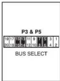
P7andP10
Auxsends/Returnlevelsourceselect
ThisconfiguresthesourcefortheAuxsendlevelcontrols.
TosourcetheStereobus, linkpins 1 - 3 and 2 - 4 (FactoryPre-set). TosourcetheMonitorReturns I to4, link pins 3 - 5 and 4 - 6. P10 configures the left hand side oftheStereobusandMonitorReturns I and2.P7 configurestherighthandsideoftheStereobusand MonitorReturns3and4.

P4 and P6
Monitor Return Bus Select
The Monitor Return outputs can be configured to feed the Aux sends.
To disable the Monitor Returns (Factory Pre-set), link pins 1 – 2 and 7 – 8 on both jumpers.
To feed the Aux buses, link pins 3 – 4 and 9 – 10 on both jumpers.
P6 configures the Monitor Returns 1 and 2.
P4 configures the Monitor Returns 3 and 4.
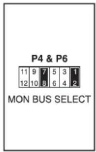
PII
Stereo Return Switch Source
To define the source for the Stereo Return switch to be the stereo return signal, link pins 1 - 3, 2 - 4, 5 - 7 and 6 - 8 (Factory Pre-set).
To convert the Stereo Return switch to a Monitor Mix switch, which sends the Stereo Bus or the Monitor Returns 1 to 4 to the Control Room speakers, link pins 3 – 5, 4 – 6, 7 – 9 and 8 – 10.

PI2
Monitor 2 Cut Disable / Enable
To enable the external Monitor cut to be active, link pins 2 - 3 (Factory Pre-set).
To disable the function, link pins 1 - 2.
Applying an active low to pins on the 25 way D Type connector controls it.
This is located on the back panel.

PI3
Tape I Sensitivity Adjust Switch
To increase the sensitivity of the Tape I input to -6dBu, link pins 1-2, 3-4, 5-6 and 7-8.
To select unity gain fit no jumpers (Factory Pre-set).

PI4
Headphones Source Select
The source for the Headphones output can follow the Control Monitors or Monitor 2.
To select the Control Monitors (Factory Pre-set), link pins 3-5 and 4-6.
To select Monitor 2, link pins 1 - 3 and 2 - 4.

P15
Remote Mute / VCA Control Select
To enable the remote mute facility for the Control Room Monitors, link pins 3 - 4. (Factory Pre-set).
Applying an active low to a pin on the 25 way D Type connector controls the remote mute.
This is located on the back panel.
To enable Stereo Bus to be cut externally, link pins 5 – 6. To enable Monitor 2 to be cut externally, link pins 1 – 2.
Note:- If fitted with optional VCAs, link pins 7 – 8 to provide external control.

P16
Control Room Monitor Dim Select
To enable the Dim control (Factory Pre-set), link pins 2 - 3. The attenuation level is set at -20dB.
To disable the Dim control, link pins 1 - 2.

PI7
Fader Start Select
To enable the fader start link, pins 2 - 3.
To disable the function, link pins 1 - 2 (Factory Pre-set).

LB6AuxMasterCommsModule JumperandSwitchOptions-GL1868

PI UserTally/OnAirSelect
ToselecttheinternalUserTallyindicator, linkpins 1 - 3 (FactoryPre-set). ToselecttheexternalUserTally, linkpins 3 - 5. Applyinganactivelowtoapinonthe25wayDType connectorcontrolstheexternalUserTally. Thisislocatedonthebackpanel. ToactivateOnAirMode, linkpins 4 - 6 (FactoryPre-set). Todisableit, linkpins 2 - 4.

P2 SlateDestinationSelect
ToenabletheoscillatortoslatetotheStereoBus,linkpins 1–3(FactoryPre-set). ToenableittoslatetotheGroupBuses,linkpins 2 – 4 (FactoryPre-set). TodisableslatetotheStereoBus,linkpins 3 – 5. TodisabletheslatetotheGroupBuses,linkpins 4 – 6.

P3 CommsOutput/CommstoMonitor2
ToenablethecommsignaltoroutetotheCommsoutput, linkpins 3 - 5 (FactoryPre-set). FortheoscillatorotortoroutetotheCommsoutputlinkpins 1 - 3. ToenablethecommsignaltoroutetotheMonitor2 output, linkpins 4 - 6 . TodisablethecommstoMonitor2, linkpins 2 - 4 (FactoryPre-set).

System Architecture
6
Contents
BB100 Meterhood Layouts....6-3
Power and Ribbon Harness Locations 6-4
BB100 Meterhood Layouts

BB100 22 Position Meterhood

BB100 30 Position Meterhood

BB100 30 Position Meterhood

BB100 38 Position Meterhood

BB100 38 Position Meterhood

Power and Ribbon Harness Locations
To gain access to the power and ribbon harnesses remove the underside panel. See the following diagrams for the location and function of the harnesses.
Power Distribution Diagram
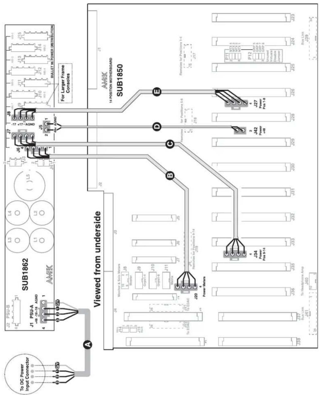
4 Core DC Power Cable to 4 Way Power Molex 1.8 Meters

[Non-Text]
-
CABHARNBB100-02
4 Way Power Molex 345mm

CABHARNBB100-02
4 Way Power Molex 345mm
[Non-Text]
CABHARNBB100-01
2 Way Power Molex 155mm
(1)
CABHARNBB100-02
4 Way Power Molex 345mm


Motherboard Harness Locations

Power Distribution and Harness Location (1851)
Viewed from underside
![graph TD A["AMEK"] --> B["J1"] B --> C["J2"] C --> D["Sub1851 8 Position Motherboard"] D --> E["To Back Panel SUB 1859 J2"] D --> F["To Sub 1862 Power Distribution J9 - J15"] D --> G["To Back Panel SUB 1859 J2"] E --> H["16 J4 Remotes for Positions 5-8"] F --> I["16 J3 Remotes for Positions 1-4"] G…](/content/2026/06/1362747/images/29e606d864589e256a4ccc34aa5ac120ddf76c9fcc9e851efd8d2c4c18ce0745.jpg)

CABHARNF16-235
16 Way Transition Header to Female Header

CABHARNBB100
4 Way Power Molex

CABHARNF16-235
16 Way Transition Header to Female Header

BUS LINK HARNESS
34 Way Female IDC Headers

BUS LINK HARNESS
34 Way Female IDC Headers
Maintenance
7
Contents
Maintenance....7-3
Removing the Modules 7 - 3
Audio and Level Alignment 7-3
Moving Coil Meter Alignment 7-3
Oscillator Level 7 - 3
Clean-Feed Trim. 7 - 4
Maintenance

There are no user serviceable parts in the console, all maintenance work should be carried out by Soundcraft or the authorised dealer.
The unit should be cleaned with a soft brush around the controls. DO NOT use solvent cleaners under any circumstances.

Removing the Modules
Modules are taken out by removing the fixing screws at the top and bottom ends. The modules are removed by pulling them directly upward. Never remove or refit the modules with the power on.
Audio and Level Alignment
Bargraph meter calibration
The console bargraph meters are calibrated during factory testing to read '0' for output levels of +4dBu. Level indication is by 28 segment LED bargraph meters, which are located in the meterhood.
The meters read Group Output, Stereo Mix or 2 Track Returns.
Where fitted, the two far right meters read the PFL/AFL bus.
The meters can be set to read VU or PEAK by the switch on the Stereo Master module LB4.
The trim adjustments for each Group meter are accessed through the top faceplate of each Group module (LB2).
The trim adjustments for the Clean-feed output meters (optional extras) are accessed through the top faceplate of each Group module (LB2).
The trim adjustments for the Monitor output meters are accessed through the top faceplate of the Stereo Master module (LB4).
The trim adjustments for the PFL/AFL meters are accessed through the top faceplate of the Stereo Master module (LB4).
Moving Coil meter Alignment
The console VU meters are calibrated during factory testing to read '0' for output levels of +4dBu. The fine trim adjustments are located on the front of the meterpanel.
Oscillator Level
The trim adjustment for the Oscillator is accessed through the top faceplate of the Auxiliary Master module (LB6).
(Factory Pre-set @ +4dB).
Clean-Feed Trim
The clean-feed null trim is used to optimise clean feed attenuation. (Factory Preset).
The trim adjustment for the null is accessed through the top faceplate of the Dual Group module (LB2).
The null trim is used to cancel the pre stereo bus signal with the chosen clean-feed input modules direct output.
The result in cancellation appears on the clean-feed output.
Power and Ribbon Harness Location
To gain access to the power and ribbon harnesses remove the underside access panel. See Chapter 6 for location and function of harnesses.
Specifications

Contents
Technical Specification 8 - 3
Console Types 8 - 3
Technical Specification
Console Types
All specifications for the BB100 console apply to consoles that are installed completely in accordance with Soundcraft's recommendations. This includes recommendations on power supply cables and grounding.
The figures in this specification are typical figures measured on a console, immediately after completing normal production tests.
Figures will therefore vary slightly from console to console and the results here should not be regarded as ‘guaranteed minimum performance’. They should be taken only as indicative of the results that might be obtained.
| Noise | ||
| Microphone equivalent input noise | Measured at the channel insert point, 22Hz – 22kHz band, RMS.Input terminated with 200 ohm source. Gain +70 dB. | Typically -127 dBu |
| One Line Input to Stereo Bus | Measured at the Stereo Bus output, 22Hz – 22kHz band, RMS. Gain unity | Typically -89 dBu (14 position frame) |
| Total harmonic distortion | ||
| Mic input to Main output | Measured at the Stereo Bus output with 10K or 600 ohm load. Test signal -30 dBu @ 1 kHz, Gain 40 dB. 22Hz – 22kHz band, RMS. | <0.03% |
| Line input to Main output | Measured at the Stereo Bus output with 10K or 600 ohm load. Test signal +20 dBu @ 1 kHz, Gain unity. 22Hz – 22kHz band, RMS. | <0.01% |
| Frequency response | ||
| Mic input to Main output | All Filters & EQ out. Measured at the Stereo Bus output with 10K load. Test signal -40 dBu, Gain 60 dB. | +/- 0.5dBu (20Hz – 20kHz) |
| Line input to Main output | All Filters & EQ out. Measured at the Stereo Bus output with 10K load. Test signal +20 dBu, Unity gain. | +/- 0.5dBu (20Hz – 20kHz) |
| X-Talk | ||
| Channel breakthrough | Channel I to Subgroup I, Channel 4 to Subgroup 4. Test signal +20 dBu to Channel I, Unity gain, 200 ohm load to Channel 4. Measured @ Subgroup output 4. | Better than -90dB (40Hz – 15kHz) |
| Channel Pan cut-off | Channel I to Subgroup 4, Pan hard right, Test signal +20 dBu to Channel I, Unity gain, Measured @ Subgroup output 3. | Better than -65dB @ 1kHz |
| Headroom | ||
| Mic input Measured at the channel insert point. Gain 10 dB. PAD in. | >+25dBu | |
| Line input Measured at the channel insert point. Gain unity. | >+25dBu | |
| Subgroup & Stereo Bus output | Measured at the Stereo Bus output with 600 ohm load. Gain unity. | >+25dBu |
| Impedance | ||
| Mic input Measured using Audio Precision System One protocol | >1k2 @ 1kHz | |
| Line input Measured using Audio Precision System One protocol | >15k @ 1kHz | |
| Outputs Measured using Audio Precision System One protocol | <70 ohm @ 1kHz | |
| Equaliser & Filter | ||
| LBI Mono Input Channel | ||
| HF The HF control gives 18dB of cut or boost switchable at frequencies 6kHz or 12kHz. | ||
| LF The LF control gives 18dB of cut or boost. The frequency switch selects between 40 Hz and 80Hz. Using the X3 switch multiplies the selected frequencies by three giving a selection of 120Hz or 240Hz. | ||
| HMF The HMF cut and boost control gives a range of ± 14dB. The HMF frequency control gives a variable frequency range of 300Hz to 6kHz. Using the X3 switch multiplies the selected frequencies by 3 giving a range of 900Hz to 18kHz. Using the Q switch selects either 0.7 or 1.3 Q Factor. | ||
| LMF | The LMF cut and boost control gives a range of ± 14dB. The LMF frequency control gives a variable frequency range of 40Hz to 800Hz. Using the X3 switch multiplies the selected frequencies by three giving a range of 120Hz to 2.4kHz. Using the Q switch selects either 0.7 or 1.3 Q Factor. | |
| HI-PASS Filter | The HP switch inserts a HI-PASS filter into the signal path. The -3dB point is fixed at 80Hz at 18dB per octave. | |
LBS Stereo Input Channel
| HF The HF control gives 18dB of cut | or boost switchable at frequencies 6kHz or 12kHz. |
| LF The LF control gives 18dB of cut | or boost. The frequency switch selects between 40 Hz and 80Hz.Using the X3 switch multiplies the selected frequencies by three giving a selection of 120Hz or 240Hz. |
| MF The MF cut and boost control gives | a range of ± 14dB. The HMF frequency control gives a variable frequency range of 80Hz to 5kHz. Using the X3 switch multiplies the selected frequencies by 3 giving a range of 240Hz to 15kHz.Using the Q switch selects either 0.7 or 1.3 Q Factor. |
| HI-PASS Filter | The HP switch inserts a HI-PASS filter into the signal path.The -3dB point is fixed at 80Hz at 18dB per octave. |
Power Consumption
| 10-4-2 BB100 Console 0.5kVA | ||
| 32-8-2 BB100 Console 1.2kVA |
Notes:-
- 0dBu = 0.775 Volts.
- Published specifications apply to standard consoles.
- All measurements taken using the Audio Precision System One test set.
- Where no load impedance is specified, the equipment should be loaded with 10K ohms or greater.
- These figures are typical of performance in a normal electromagnetic environment. Performance may be degraded in severe conditions.
- Soundcraft has an established policy of seeking improvements to designs, specifications and manufacture of its products. Alterations take place continually, often without notice outside the company. Soundcraft's literature must not be taken as an infallible guide to the specifications available despite a considerable effort to produce up to date information.
BB100
Schematics
9
Contents
| Description PCB Circuit Diagram | ||
| BB100 Modules | ||
| System Block Diagram N/A N/A | ||
| LB1 Mono Input Module 1864B2 B100/3/001 | ||
| LBS Stereo Input Module 1865-2 B100/3/002 | ||
| LB2 Dual Group Module 1866B B100/3/014 | ||
| LB4 Stereo Master/Monitor Module 1867B B100/3/016 | ||
| LB6 Aux Master/Comms Module 1868B2 B100/3/003 | ||
| System Boards | ||
| 14 Position Motherboard 1850B B100/3/015 | ||
| 8 Position Motherboard (Expansion) 1851 B100/3/019 | ||
| Mono Connector Card 1852 B100/3/006 | ||
| Stereo Connector Card 1853 B100/3/020 | ||
| Main Connector EMC Card | 1854 | B100/3/007 |
| Main Connector Card 8 Group | 1855 | B100/3/017 |
| Main Connector Card 4 Group | 1856 | B100/3/012 |
| I/O 56 Way EDAC EMC Sub Card | 1857 | B100/3/013 |
| I/O 56 Way EDAC Connector Card | 1858 | B100/3/005 |
| Channel Remote Interface | 1859 B100/3/009 | |
| Master Remote Interface | 1860 B100/3/010 | |
| Stereo Headphone Amplifier | 1861 B100/3/008 | |
| Power Distribution Card | 1862 B100/3/004 | |
| 28 Segment Meter Card (4 Bars) | 1863 | B100/3/011 |
| Meter Switch Card | 1869 B100/3/018 | |
All Circuit Diagrams and Overlays are arranged in numerical order.
© 1998 Soundcraft - A division of Harman International Industries Ltd.
H A Harman International Company
- CONTENTS
- INTRODUCTION
- 1
- PRECAUTIONS AND SAFETY INSTRUCTIONS
- CAUTION
- IMPORTANT
- WARNING
- BB100 HARDWARE
- MAIN CONSOLE FEATURES INCLUDE
- INSTALLATION
- 2
- POWER SUPPLIES
- POSITIONING THE POWER SUPPLY UNIT(S)
- CHECKING AND CONNECTING THE POWER UNITS
- THIS APPARATUS MUST BE EARTHED
- MOUNTING
- EARTHING
- CLEAN EARTH
- EARTH LOOPS
- MICROPHONE CABLES
- WIRING CONVENTIONS
- SIGNAL LEVELS
- MODULE REMOVAL
- MAINTENANCE
- EMC PRECAUTIONS
- CONSOLE SHIPPING AND STORAGE
- EMC ENVIRONMENT
- MAINS SUPPLIES
- RF IMMUNITY
- STATIC AND FURNISHINGS
- DO-IT-YOURSELF TESTING
- ANTENNAS AND RECEIVERS FOR WIRELESS MICROPHONES
- INSTALLATION CABLES - TYPE AND LOCATION
- TYPE OF CABLE
- LOCATION OF CABLE
- CONNECTORS - TYPE AND TERMINATION OF CABLES
- TERMINATION
- HIGH RF FIELDS
- JACKFIELD CORDS
- CONNECTING UNBALANCED EQUIPMENT
- EMC PRECAUTIONS DURING MAINTENANCE
- MIXER PANELLING
- MODIFICATIONS BY THE CONSOLE'S OWNER
- BB100 CHASSIS DIMENSIONS
- POWER SUPPLIES & CABLING
- 3
- POWER SUPPLIES & CABLING 3-3
- MAINS LEAD CONNECTIONS
- FOR UK USER ONLY
- SUPPLY TYPES & DESCRIPTION
- MAIN VOLTAGE SELECTION
- MPS 5
- REPLACING MAINS FUSE – PSU 300 / MPS 5
- LOCATION AND COOLING AIR
- MAGNETIC FIELDS
- DC CABLES
- TECHNICAL SPECIFICATIONS
- CONNECTOR PINOUTS
- OUTPUT VOLTAGE ADJUSTMENTS
- OUTPUT VOLTAGE ADJUSTMENTS - MPS 5
- OUTPUT VOLTAGE ADJUSTMENTS - MPS 20
- CONNECTORS
- 4
- CONNECTIONS. 4 - 3
- CONNECTIONS
- BACK PANEL LAYOUT 4 GROUP
- BACK PANEL LAYOUT 8 GROUP
- FADER STARTS / MONITOR LOGIC / REMOTE MUTES
- FADER START
- MONITOR LOGIC / REMOTE MUTES
- FADER STARTS
- MONITOR LOGIC
- 25 WAY FEMALE D TYPE
- REMOTE MUTES
- 15 WAY FEMALE D TYPE
- 56 WAY I/O EDAC CONNECTIONS
- INPUT AND OUTPUT CONNECTIONS
- MODULES
- 5
- LBIMONOINPUTMODULE
- EQUALISER
- AUXILIARYSENDS
- ROUTING
- LBSSTEREOINPUTMODULE
- LB2DUALGROUPMODULE
- METERING
- LB6AUXILIARYMASTERMODULE
- COMMS
- OSCILLATOR
- LB4STEREOMASTERMODULE
- BB100JUMPERANDSWITCHOPTIONS
- I4POSITIONMOTHERBOARD-GL1850
- PI/P5
- CLEANFEEDPOSITION5
- P2/P6
- CLEANFEED POSITION 6
- P3/P7
- CLEANFEED POSITION 7
- P4/P8
- CLEANFEED POSITION 8
- P9
- CLEANFEED POSITION 9
- PIO
- CLEANFEED POSITION 10
- PII
- VIRTUAL EARTH DISABLE OPTIONS
- PI2
- LBIMONOINPUTMODULE JUMPERANDSWITCHOPTIONS-GLI864
- PI
- SIGNALISATIONSELECT
- P2
- DIRECTSOURCE
- P3
- SIGNALISATIONSOURCE
- S31
- PFL / AFL SELECT SWITCH
- S32
- AUX I & 2 MONO STEREO SWITCH
- LBSSTEREOINPUTMODULE JUMPERANDSWITCHOPTIONS-GL1865
- STEREOINSERTPOSITIONSELECT
- S27
- S28
- A U X L & 2 MONO STEREO SWITCH
- LB2DUALGROUPMODULE JUMPERANDSWITCHOPTIONS-JP1866
- CLEANFEEDOFFGROUPSOURCE
- CLEANFEEDJUMPER
- P4
- CLEANFEEDBUSSELECTION
- P5
- RETURN AUX SEND BUS SELECT
- P6
- GROUP BUS SELECT
- P7
- REMOTE MUTE / VCA CONTROL SELECT
- P8
- SIGNALISATION SELECT
- S16
- GROUP SENDS AUX
- LB4MASTERMODULE JUMPERANDSWITCHOPTIONS-GL1867
- P1,P2,P8,ANDP9
- MONITORAUXSENDMONO/STEREOSELECT
- P3ANDP5
- AUXSENDS/RETURNLEVELDESTINATIONSELECT
- P7ANDP10
- AUXSENDS/RETURNLEVELSOURCESELECT
- P4 AND P6
- MONITOR RETURN BUS SELECT
- STEREO RETURN SWITCH SOURCE
- MONITOR 2 CUT DISABLE / ENABLE
- PI3
- TAPE I SENSITIVITY ADJUST SWITCH
- PI4
- HEADPHONES SOURCE SELECT
- P15
- P16
- CONTROL ROOM MONITOR DIM SELECT
- PI7
- FADER START SELECT
- LB6AUXMASTERCOMMSMODULE JUMPERANDSWITCHOPTIONS-GL1868
- PI USERTALLY/ONAIRSELECT
- P2 SLATEDESTINATIONSELECT
- P3 COMMSOUTPUT/COMMSTOMONITOR2
- SYSTEM ARCHITECTURE
- BB100 METERHOOD LAYOUTS
- POWER AND RIBBON HARNESS LOCATIONS
- POWER DISTRIBUTION AND HARNESS LOCATION (1851)
- 7
- REMOVING THE MODULES
- AUDIO AND LEVEL ALIGNMENT
- BARGRAPH METER CALIBRATION
- MOVING COIL METER ALIGNMENT
- OSCILLATOR LEVEL
- CLEAN-FEED TRIM
- POWER AND RIBBON HARNESS LOCATION
- SPECIFICATIONS
- TECHNICAL SPECIFICATION
- CONSOLE TYPES
- NOTES
- SCHEMATICS
- 9
Brand : SOUNDCRAFT
Model : BB100
Category : Audio Mixer