MPR-47S-D - Analyseur réseau électrique ENTES - Free user manual and instructions
Find the device manual for free MPR-47S-D ENTES in PDF.


| Product Type | Multifunction Power Protection Relay |
| Model | MPR-47S-D |
| Brand | ENTES |
| Dimensions (WxHxD) | 96 x 96 x 70 mm (panel cutout 92x92 mm) |
| Weight | Approx. 0.5 kg |
| Power Supply | 100-240 V AC/DC (50/60 Hz) |
| Measured Parameters | Voltage (L-N, L-L), Current, Frequency, Power Factor, Active/Reactive/Apparent Power, Energy |
| Display | Backlit LCD, 4 lines x 20 characters |
| Communication | RS485 Modbus RTU (optional) |
| Protection Functions | Overvoltage, Undervoltage, Overcurrent, Undercurrent, Overfrequency, Underfrequency, Phase Sequence, Phase Imbalance |
| Input Voltage Range | 50-300 V AC (L-N) / 100-520 V AC (L-L) |
| Input Current Range | Via external CT: 1A or 5A secondary |
| Mounting | Panel mount (flush) |
| Ambient Temperature | -10°C to +55°C |
| Ingress Protection | IP54 (front panel) |
| Safety Standards | IEC 61010-1, IEC 61557-12 |
| Certifications | CE, RoHS |
| Cleaning | Wipe with a dry, soft cloth. Do not use solvents. |
| Spare Parts & Repairability | Contact ENTES service center for genuine parts; device is not user-serviceable. |
| Manual Languages | English (default), other languages available via translation request |
Frequently Asked Questions - MPR-47S-D ENTES
User questions about MPR-47S-D ENTES
0 question about this device. Answer the ones you know or ask your own.
Ask a new question about this device
Download the instructions for your Analyseur réseau électrique in PDF format for free! Find your manual MPR-47S-D - ENTES and take your electronic device back in hand. On this page are published all the documents necessary for the use of your device. MPR-47S-D by ENTES.
USER MANUAL MPR-47S-D ENTES
INDEX
1. SAFETY AND WARNINGS.... 3
Warning ....3
Safety....3
Warranty 3
2. OPERATING CONDITIONS 4
3. INTRODUCTION 5
3.1 General Features....5
3.2 Applications....6
3.3 MPR-4X Series Product....6
3.4 Overview and Interface....7
3.4.1 Terminals 7
3.4.1.1. MPR-4X Series Rear Panel....7
3.4.1.2. MPR-4X-OG/OGT Series Rear Panel 8
3.4.1.3. MPR-4X-PM Series Rear Panel 8
3.4.2. Screen 9
3.4.3. Button Functions....10
3.5 Terminal Structure....11
4. CONNECTION 12
4.1. 3P4W (Three Phase Four Wires) Connection....12
4.2. 3P3W (3 Phase 3 Wires) Connection....12
4.3. Aron without Neutral Connection ....13
4.4. 3P4W BLN (3 Phase Balanced with Neutral) Connection....13
4.5. 3P3W BLN (3 Phase Balanced without Neutral) Connection ....13
4.6. Connection Test....14
5. OPERATING INSTRUCTIONS.... 15
5.1 Measurement Screens....15
5.1.1 Current, Voltage and Frequency Screens....15
5.1.2 Power and Power Factor Screens 17
5.1.3 Energy and Time Screen 18
5.1.4. THD and Harmonics Screens (MPR-46X, MPR-47X ve MPR-42-OGT)....21
5.1.5. Minimum, Maximum and Demand Screens 22
5.1.6. Ethernet Parameter Displaying Screens (MPR-4XSE)....27
5.2 Setup Screen....30
5.2.1 Device Installation Settings....30
5.2.2. Display Settings....35
5.2.3.Time Settings 36
5.2.4.RS-485 Communication Settings....38
5.2.5 Ethernet Communication Systems 40
5.2.6 Input Parameter Settings....43
5.2.7 Output Parameter Settings 45
5.2.8. Recording Settings 46
5.2.9. Selecting Parameter to Be Recorded 46
5.2.10. Pulse Input Settings 49
5.2.11. Pulse Output Settings ....51
5.2.12. Operating Hours Settings ....53
5.2.13. Alarm Settings....54
5.2.14. Tariff Settings....57
5.2.15. Reset Settings 58
5.2.16. System Settings....61
5.2.17.Analog Output Settings....64
5.3. Reporting Screen 68
6. TECHNICAL FEATURES AND APPENDIX 69
Warning
Installation of this device on the panel should be carried out only by authorized personnel. The manufacturer cannot be held responsible in any way for any errors that may occur if the instructions set out in this document are not followed. Please read the safety information and warnings carefully before installation.
- Disconnect the power on the line that will come to the device on the panel beforeconnecting the device. If it is not done, there is a risk of fatal injury and a risk of device failure.
- Before connecting, check the back panel of the device to make sure that the correct terminals are properly connected.
- Device should not be connected to network if it has any damage.
- Please do not open front panel or inside of the device if it is still connected to network.
- Do not attempt to clean the device with a solvent or another similar material. Use only a dry piece of cloth.
- Secondary side of current transformers shall not be kept open while primary side of them is still energized. It may cause damage on device, fire and some serious injury.
- Please fix the connection of current transformers with using washer or cable lug in order to protect against mechanical pulling.
- Please always use appropriate supply voltage for the device.
- Contact your authorized seller in case of any problems with your device.
• Device is only for panel mounting. - F Type fuse must be used and its current limit must be 1 A.
Safety
Read the entire user manual before using the device.
- A switch or circuit breaker must be connected between the network and the auxiliary supply of the device.
- Connected switch or circuit breaker must be in close proximity to the device.
- Connected switch or circuit breaker must be marked as the disconnecting device for the equipment
Warranty
Device has a 2 (two) year warranty. Any repairs on the device must be done only by the manufacturer. Otherwise, the device warranty will be invalid.
2. OPERATING CONDITIONS
| Operating Conditions Range | |
| Supply Voltage 50 ~ 270 VAC/DC ± %10 | 24~60 VAC/DC(Just for MPR-4X-D and MPR-4X-OG-D series) |
| Supply Frequency 50 / 60 ± %10 Hz | |
| Maximum Measuring Current 5,5 A | |
| Maximum Measuring Voltage 300 VAC (VLN) / | 480 VAC (VLL) |
| Operating Temperature - 10 ~ +70 oC | |
| Storing Temperature - 20 ~ +80 oC | |
| Maximum Ambient Humidity % 95 | |
| Baud Rate 2400 ~ 115200 bps | |
3.1 General Features
- Wide supply voltage range
- Custom STN display with backlight
• 4 voltage measuring inputs
• 4 current measuring inputs
• 4 languages options
• 16MB internal memory
• Real time clock - Alarm
• Hour counters (Operating hour and total hour) - Communication via RS-485 Modbus RTU
- Ethernet interface and Modbus TCP communication
- Module input
- MM-OG-26 big box module:
- 2 Digital Inputs
• 2 Digital Outputs
- 2 Relay Outputs
- 5A/250VAC; NO
- 2 Analog Outputs
• 0-20mA, 0-24mA, 4-20mA
- 0-10V, 0-5V, 5\~+5V,-10\~+10V
- Measured parameters: Current, Voltage, Power, Energy, THDI and THDV, Power factor and cosφ
- 96 x 96 panel mount
• Event records storage and management - User password
- Changing primary and secondary values of current and voltage transformers
• Measure on 3 Phase with Neutral, 3 Phase without Neutral, Aron connected systems - Contrast setting
- Demand time setting
• Daylight savings time switching - Tariff settings
3.2 Applications
MPR-4 Series devices are microprocessor-based devices which are designed to measure all parameters of an electrical network, calculate the consumption values and display these on its LCD screen. Measured parameters will be recorded in real-time thanks to internal flash memory and Real Time Clock chip. It can be read and monitored remotely with Modbus RTU protocol via RS-485 line and Modbus TCP protocol via Ethernet interface in models with Ethernet.
3.3 MPR-4X Series Product
| Product Code | Boyutlar | Basic Parameter* | Active Energy Class 0.5 | Active Energy Class 1 | Netural Current Input | % THD V/I | Sag/Swell | Individual Harmonics | RS-485 | Ethernet | Digital Input/Output | Analog Output | Relay Output (Alarm Contact) | RTC | Sampling Rate | Memory (MB) | Current / Voltage Unbalance | Pulse Counter | Run Hour / Alarm / Event Log | Log Recording | X/5, X/1 | X/333mV | Plug & meter | 24-60 VAC/DC | 50-270 VAC/DC | Pcs. / Carton |
| 50-270 VAC/DC Supply | ||||||||||||||||||||||||||
| MPR-45 | 96x96 | ● | ● | ● | *** | ● | 128 | * | ● | ● | ● | 24 | ||||||||||||||
| MPR-45S | 96x96 | ● | ● | ● | ● | *** | ● | 128 16 | * | ● | ● | ● | ● | 24 | ||||||||||||
| MPR-46 | 96x96 | ● | ● | ● | ● | *** | ● | 128 | * | ● | ● | ● | 24 | |||||||||||||
| MPR-46S | 96x96 | ● | ● | ● | ● | ● | *** | ● | 128 16 | * | ● | ● | ● | ● | 24 | |||||||||||
| MPR-46S-PM | 96x96 | ● | ● | ● | ● | *** | ● | 128 16 | * | ● | ● | ● | ● | ● | 24 | |||||||||||
| MPR-47S | 96x96 | ● | ● | ● | ● | ● | 51 | ● | *** | ● | 128 16 | ● | * | ● | ● | ● | ● | 24 | ||||||||
| MPR-47S-0,5 | 96x96 | ● | ● | ● | ● | ● | 51 | ● | *** | ● | 128 16 | ● | * | ● | ● | ● | ● | 24 | ||||||||
| MPR-47S-PM | 96x96 | ● | ● | ● | ● | 51 | ● | *** | ● | 128 16 | ● | * | ● | ● | ● | ● | ● | 24 | ||||||||
| MPR-47SE | 96x96 | ● | ● | ● | ● | ● | 51 | ● | ● | *** | ● | 128 16 | ● | * | ● | ● | ● | ● | 24 | |||||||
| MPR-47SE-0,5 | 96x96 | ● | ● | ● | ● | 51 | ● | ● | *** | ● | 128 16 | ● | * | ● | ● | ● | ● | 24 | ||||||||
| 24-60 VAC/DC Supply | ||||||||||||||||||||||||||
| MPR-47S-D | 96x96 | ● | ● | ● | ● | ● | 51 | ● | *** | ● | 128 16 | ● | * | ● | ● | ● | ● | 24 | ||||||||
| MPR-47S-D-0,5 | 96x96 | ● | ● | ● | ● | ● | 51 | ● | *** | ● | 128 16 | ● | * | ● | ● | ● | ● | 24 | ||||||||
| OG Serisi (Fixed Current Terminals) | ||||||||||||||||||||||||||
| MPR-42-OGT-26 | 96x96 | ● | ● | ● | 31 2/20 | 2 | 2 | ● | 128 16 24 | ● | ● | ● | ● | ● | ||||||||||||
| MPR-42-OGT-26-0,5 | 96x96 | ● | ● | ● | 31 2/20 | 2 | 2 | ● | 128 16 24 | ● | ● | ● | ● | ● | ||||||||||||
| MPR-47S-OG | 96x96 | ● | ● | ● | ● | 51 | ● | *** | ● | 128 16 | ● | * | ● | ● | ● | ● | 24 | |||||||||
| MPR-47S-OG-D | 96x96 | ● | ● | ● | ● | 51 | ● | *** | ● | 128 16 | ● | * | ● | ● | ● | ● | 24 | |||||||||
| MPR-47S-OG-D-0,5 | 96x96 | ● | ● | ● | ● | 51 | ● | *** | ● | 128 16 | ● | * | ● | ● | ● | ● | 24 | |||||||||
3.4 Overview and Interface

3.4.1 Terminals
3.4.1.1. MPR-4X Series Rear Panel
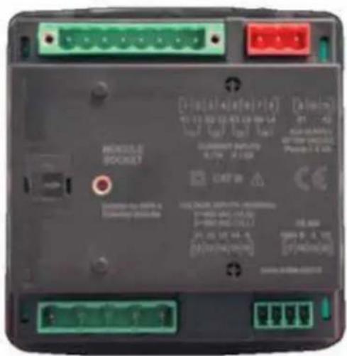
3.4.1.2. MPR-4X-OG/OGT Series Rear Panel
![MODULE SOCKET Suitable for HPVR-4 Extension Module [1] [2] [3] [4] [6] [8] R7 L7 R2 L2 R3 L3 [1] [2] [3] [4] [6] [8] CURRENT INPUTS X/1A X/1A CAT III VOLTAGE INPUTS (N/R/M/D) 8~80 V/D (V/V) 8~600 V/D (V/L) V1 V2 V3 V4 V5 [12] [13] [14] [15] [16] [17] [18] [19] [20] [1] [2] [3] [4] [6] [8] [1] [2] [3] [4] [6] [8] [1] [2] [3] [4] [6] [8] [1] [2] [3] [4] [6] [8] [17] [18] [19] [20]](/content/2026/06/1362324/images/a30eddc540a0206e1bb9e2bbb449244171a93622a21ea40ded3cdfa19abe4d4b.jpg)
3.4.1.3. MPR-4X-PM Series Rear Panel
![K3 L3 K2 L2 K1 L1 8 1 1 1 A0 2 1 L1 11 3 1 M0 4 1 K2 5 1 L3 12 6 1 M0 7 1 K3 13 8 1 L4 13 VOLTAGE INPUTS (50/62Hz) 8 - 400 VAC ( VLA) 5 - 490 VAC ( VLL) V1 V2 V3 VE N. 12 13 14 15 16 A1 A0 AN SUPPLY 40-30VAC DC CAT ID RIS 485 GRID BI-3 AI+1 TR [17] 18 19:20](/content/2026/06/1362324/images/2221a0954fea7cb246c10b67519977d2d844d32971b993a3a65b7d0c4a907544.jpg)
3.4.2. Screen

1- Indicates on which quadrant the network is operating.
2- Indicates that the corresponding screen is one of THD, MIN, Maximum or DEMAND screens.
3- Indicates the total value. (I.e. ΣTHD)
4- Indicates the percent values.
5- Indicates for which tariff the energy measurement is.
6- Indicates negative value.
7- Indicates L1, L2, L3 and L1-2, L2-3 and L3-1 measurements.
8- Indicates energy value or time.
14- Indicates the unit of the energy value
15- Indicates measurement results of related screen.
16- Indicates the unit of the measured values.
17- Indicates the value is cos∅ or power factor.
18- Indicates whether the alarm is active.
19- Indicates a warning.
20- Indicates whether a connection failure.
21- Indicates that the alarm clock is active.
22- Indicates that the device is locked.
23- Indicates which pulse output is active.
24- Indicates which digital output is active.
25- Indicates which digital input is active.
26- Indicates the measurement is inductive or reactive.
3.4.3. Button Functions
In addition to their main functions, the 5 buttons on the front panel can be used as shortcut buttons for easily reaching screens. Button functions descriptions below.
ESC button (9) : It has 3 main functions:
- Exiting from any menu is done by pressing ESC button
- While on measuring screen: As seen on the symbols (V I F) above the button, it is used to monitor between voltage, current and frequency measurement screens.
- As seen on the symbols (Event) below the button, event screen is reached when pressed for 3 seconds
BACK Button (10) : It has 3 main functions:
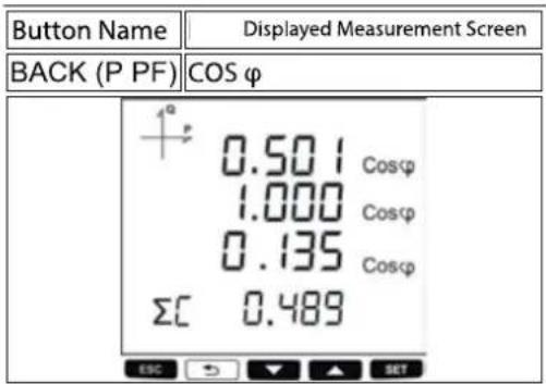
- While on measuring screen: As seen on the symbols (P PF) above the button, it is used to navigate between active power, reactive power, apparent power, power factor and Cos φ measurement screens.
- It is used to select the previous digit while entering a numerical value in the menu or to return to the previous menu level.
- As seen on the symbols (Test) below the button, connection control is reached when pressed for 3 seconds.
Down Button (11): It has 2 main functions:
- While on measuring screen: As seen on the symbols (E Clock) above the button, it is used to navigate between import/export active energy consumption, reactive energy consumption, tariff and time information screens.
- While on menu screens: It is used to navigate between menu options and to decrease a value to be adjusted.
Up Button (12) : It has 2 main functions:
- While on measuring screen: As seen on the symbols (THD H) above the button, it is used to navigate between THDV, THDI and individual harmonic measurement screens.
- While on menu screens: It is used to navigate between menu options and to increase a value to be adjusted.
SET Button (13) : It has 3 main functions:
- It enables access to menu screens when pressed for 3 seconds. When the PIN is active, a password is asked before entering the menu. After the correct password is entered, access to menu is allowed.
- It is used to reach the desired adjustment screen and to save the changed settings. Pressing the button is enough for this operation.
- While on measuring screen: It is used to navigate between Min, Max, Demand and Maximum Demand screens.
3.5 Terminal Structure
1) 50-270 VAC Supply Voltage 3 terminal connections (2 pins)
2) Current measuring input terminal block (6 pin): L1 L2 L3
3) Voltage measuring input terminal block (5 pins): L1 L2 L3 VE (Ground) and N
4) RS-485 terminal block (4 pins)
5) Module input:
MM -MV -26 big box module:
2 digital inputs
| 2 | digital | outputs |
| 2 | relay | outputs |
| 5A/250VAC; | NO |
2 analog outputs
| 0-20mA, | 0-24mA, | 4-20mA | |
| 0-10V, | 0-5V, | ± 5V, | ±10V |
4. CONNECTION
Device has 5 different connection configurations. These configurations are explained with diagrams below:
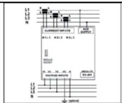
4.1. 3P4W (Three Phase Four Wires) Connection
In this connection type, four voltage and four current connections are made, including the neutral line.

MPR-4X PR-4X-OG/OGT
M

MPR-4X-PM
Note: Neutral current transformer which connected to K4 and L4 is optional in MPR-4X.
4.2. 3P3W (3 Phase 3 Wires) Connection
For this configuration, three voltage connections and four current connections are used.

MPR-4X MPR-4X-OQ

MPR-4X-PM

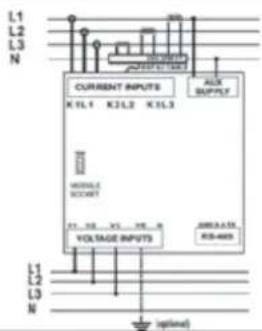
Note: Neutral current transformer which connected to K4 and L4 is optional in MPR-4X.
4.3. Aron without Neutral Connection
Three voltages, two current connection is made in this connection type.

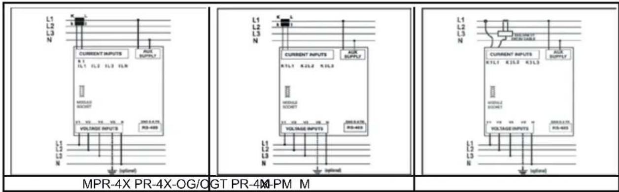
4.4. 3P4W BLN (3 Phase Balanced with Neutral) Connection
For this configuration, four voltage connections and one current connection is used. The device shows the same current value, which is measured from the first phase, for the rest phases.
4.5. 3P3W BLN (3 Phase Balanced without Neutral) Connection
For this configuration, three voltage connections and one current connection is used. The device shows the same current value, which is measured from the first phase, for the rest phases.

4.6. Connection Test
After finishing device connections, you can check the connection that you've done by using the automatic test function.
When you press the BACK button for 3 seconds, it switches to test mode. The following conditions must be applied for proper operating test mode:
- At least 20% of nominal voltage must be applied to the voltage measurement inputs.
- At least 10% of the nominal current must be applied to the current measurement inputs.
- The angle difference between current and voltage inputs must be less than 30 degrees (cosφ value should be between inductive 0,87 and capacitive 0,87.)
During connection test, the device controls the connections and it can correct them internally or it can leave the physical correction to the user.
If there's an error between voltage inputs, it can only be corrected by changing physical connections.
If you encounter Error 12, make sure that all connections are done and make sure that the test conditions stated above are applied.
At the following table, possible connection errors that may be encountered during connection test and their corresponding error codes that are displayed on the device screen.
| Test Error Code | Test Code Description |
| 0 All connections are correct | |
| 1 Phase-1 | current direction is reversed |
| 2 Phase-2 | current direction is reversed |
| 3 Phase-3 | current direction is reversed |
| 4 Phase-1 | and Phase-2 voltage connections are reversed |
| 5 Phase-1 | and Phase-3 voltage connections are reversed |
| 6 Phase-2 | and Phase-3 voltage connections are reversed |
| 7 Voltage connection phase sequence will be changed L1, L2, L3 to L3, L1, L2 | |
| 8 Voltage connection phase sequence will be changed L3, L2, L1 to L3, L1, L2 | |
| 9 CT-1, CT-2 will be swapped. | |
| 10 CT-1, CT-3 will be swapped. | |
| 11 CT-2, CT-3 will be swapped. | |
| 12 Test conditions are not met. | |
5. OPERATING INSTRUCTIONS
5.1 Measurement Screens
In this section, the screens to be displayed in order according to the buttons used when the device is in measurement mode are shown.
5.1.1 Current, Voltage and Frequency Screens
In this screen you can display measured Phase-Neutral values for each phases.
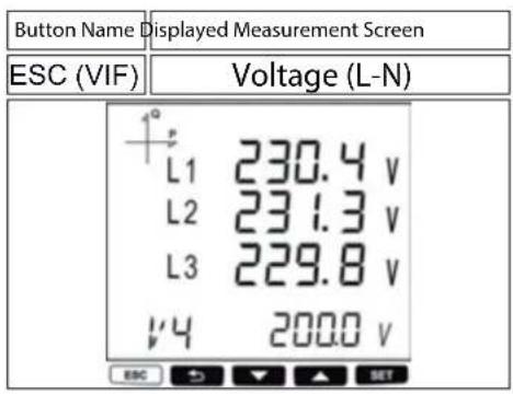
In this screen you can display Phase-Phase Voltage Values. Measured frequency value stands at the last row.

In this screen you can display measured Current and neutral Current values for each phase.
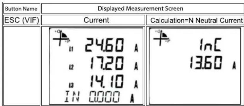
In this screen you can display measured Voltage Unbalance.

In this screen you can display Current Unbalance.

In this screen you can display Run Hour Counter.

Bu In this screen you can display how long the device has been operated.

5.1.2 Power and Power Factor Screens
In this menu you can view Total Power (sum of active, reactive and apparent power).
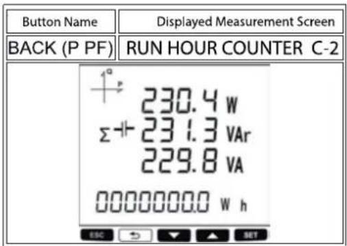
In this screen you can display Active power values for each phases. Sum of all active power values stand at the last row.
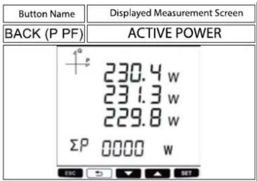
In this screen you can display Reactive Power values for each phases. Sum of all reactive power values stand at the last row.

In this screen you can display Apparent Power values for each phases. Sum of all apparent power values stand at the last row.

In this screen you can display Power Factor values for each phases. Sum of Power Factor values stand at the last row.

In this screen you can display COS values for each phases. Sum of COS values stand at the last row.
5.1.3 Energy and Time Screen
In this screen you can display Import Active Energy Value.

In this screen you can display Export Active Energy value.

In this screen you can display Import Reactive Energy Value.

In this screen you can display Export Reactive Energy value.
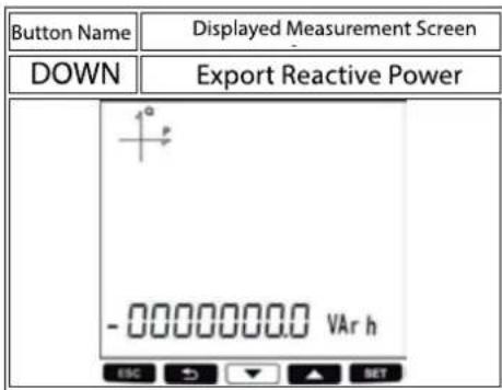
In this screen you can display Apparent Energy value.
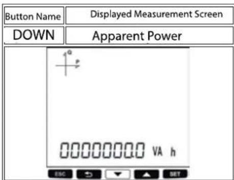
In this screen you can display Total Tariff Active Energy value.

In this screen you can display Active Tariff's Active Energy value. You can see that active tariff symbol is blinking.

In this screen you can display Energy Values belongs to adjusted tariffs.
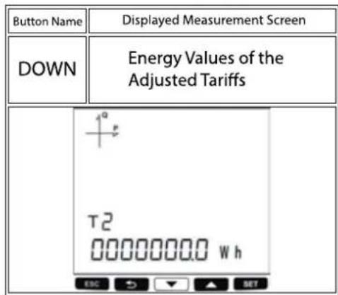
In this screen you can display the device's time.

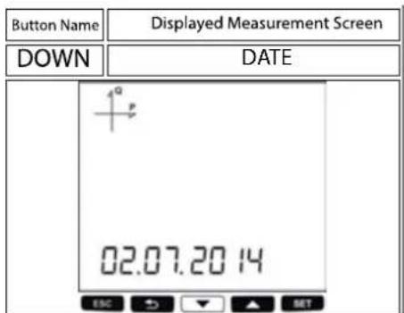
In this screen you can display the device's date.
5.1.4. THD and Harmonics Screens (MPR-46X, MPR-47X ve MPR-42-OGT)
For models with THD, only current THD and voltage THD screens will be displayed. For models with harmonics, individual harmonics for current and voltage can be displayed also.
When you press VIF button Phase-Neutral or Phase-Phase Voltage screens will be opened and in this case if you press THD H(up) button following screens will be displayed.
In this screen you can display Phase – Neutral or Phase – Phase Voltage Harmonic Distortion values for each phase.

In this screen you can or each phase measured Phase-Neutral or Phase – Phase Voltages with detailed Total Harmonic Distortion until 51. Harmonics.
You can display Voltage Harmonic values.

When you press VIF button current screen will display and after that if you press THD H button following screen will be displayed.
In this screen you can display measured Total Current Harmonic Distortion for each phase.

In this screen you can display measured Total Harmonic Distortion with Current detailed up to 51. harmonic for each phase.

5.1.5. Minimum, Maximum and Demand Screens
In this screen you can display measured Maximum Phase- Neutral Voltage values for each phase. At the last row you can see the Maximum frequency value.

In this screen you can display measured Minimum Phase- Neutral Voltage values for each phase. At the last row you can see the minimum frequency value.

In this screen you can display measured Maximum Phase- Phase Voltage values for each phase.
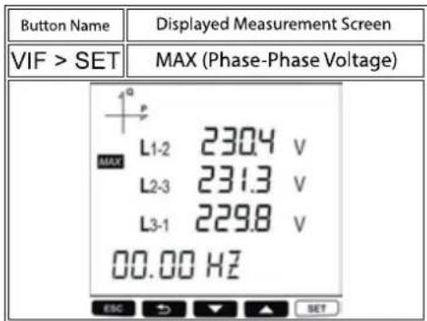
In this screen you can display measured Minimum Phase- Phase Voltage values for each phase.

In this screen you can display measured Maximum Current values for each phase
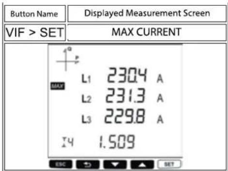
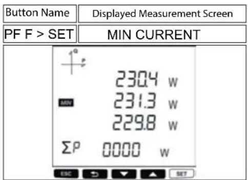
In this screen you can display measured Minimum Current values for each phase.

To see the minimum, maximum and demand values of power parameters, first select the relevant screen with "P PF" button. Afterwards, you can display the following screens with MAX/MIN DEMAND.
In this screen you can display Active Power Maximum Demand values for each phase. At the last row you can see the Total Active Power Maximum Demand value.

In this screen you can display Active Power Demand values for each phase. At the last row you can see the Total Active Power Demand value.
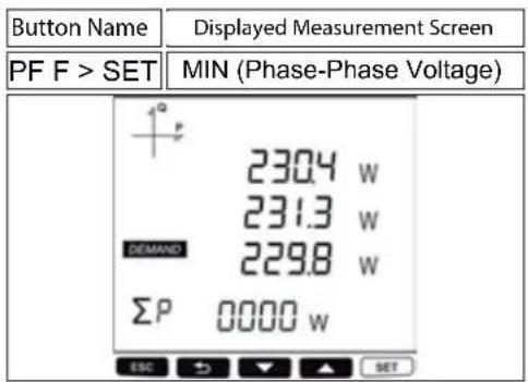
In this screen you can display Maximum Active Power values for each phase. At the last row you can see the Total Maximum Active Power value.

In this screen you can display Minimum Active Power values for each phase. At the last row you can see the Total Minimum Active Power value.
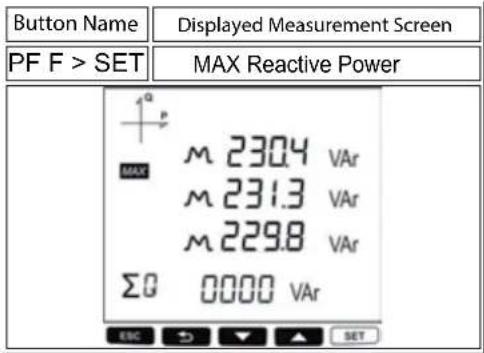
In this screen you can display Maximum Reactive Power (inductive/ capacitive) values for each phase. At the last row you can se the Total Maximum Reactive Power value.
In this screen you can display Minimum Reactive Power (inductive/ capacitive) values for each phase. At the last row you can see the Total Minimum Reactive Power value.

In this screen you can display Apparent Power Demand values for each phase. At the last row you can see the Total Apparent Power Demand value.
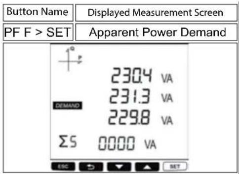
In this screen you can display Apparent Power Maximum Demand values for each phase. At the last row you can see the Total Apparent Power Maximum Demand value.

In this screen you can display Maximum Apparent Power values for each phase. At the last row you can see the Total Maximum Apparent Power value.

In this screen you can display Minimum Apparent Power values for each phase. At the last row you can see the Total Minimum Apparent Power.

5.1.6. Ethernet Parameter Displaying Screens (MPR-4XSE)
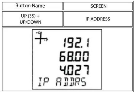
In the monitoring screen if you press Up button for 3 seconds, shortcut will be activated. Ethernet parameters screen is displayed.
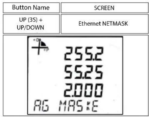
In the following screens between the screens below with UP / DOWN buttons Ethernet Connection Information can be seen.
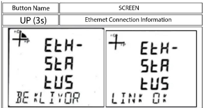
STARTING: This is the message that appears when the device is first turned on. Indicates that the Ethernet module is performing startup operations.
CONNECTED: If the device is in server mode, it indicates that a connection has been made to the device. If the device is in client mode, it indicates that a connection is made to the set server.
WAITING: If the device is in server mode, it indicates that the IP acquisition is successful and a connection is awaited from the server.
IP WAIT: Indicates that IP is expected to be issued via DHCP
HW ERROR: Indicates that there is a communication error between ethernet module and main processor.
NO CONNECTION: Indicates that Ethernet connection is not available.
DHCP ERROR: Indicates that acquisitioning IP via DHCP server was failed. This problem occurs when DHCP server is not operating properly or there is no DHCP server at the network that device connected.
IP CAKIS: Indicates that there is another device with the same IP as the device in the network to which the device is connected.
DNS ERROR: Occurs when the device is operating in client mode and the server address set cannot be resolved via the DNS server. This occurs when there is no set server address in the set DNS server address pool or there is no DNS server in the network to which the device is connected. This error does not occur when the device server address is set as IP.
SNC ERROR: This error occurs when the server that is set up does not accept connection requests while the device is running in client mode.
TKRR DEN: This message occurs when the first connection request of the server which has been set while the device is in the client mode fails and tries to connect again.
Ethernet IP address shows the IP address that the device will use for the ethernet connection when DHCP is not enabled.
The subnet mask address shows the network address which the device is connected.
The gateway address shows the address of the modem or gateway that the device is connected to the internet.

The MAC address screen shows the MAC address of the device. This value cannot be set. It can only be seen with shortcut.
| Button Name EKRAN SCREEN | |
| YUKARb(3s) +UP/DOWN | Ethernet ModuleMAC ADRESS |
 | |
5.2 Setup Screen
Accesing the Programming Menu
When the SET button of the device is pressed for 3 seconds with PIN feature activated, entry screen is displayed. When the password is entered correctly, programming menu is reached.
If PIN feature is not activated, programming menu is reached directly. Password for the device is 1234 as factory default.
5.2.1 Device Installation Settings
In order for the device to become operational, information of current and voltage transformers on the system and the connection type must be entered to the device. When the device is energized for the first time, it will require the user to enter this information. Adjust the following settings accordingly by using SET and UP/DOWN buttons.
5.2.1.1 Language Setting

Messages on the device screen can be viewed in four languages:
- Turkish
- English
- German
4.French
Note: Please contact your Sales Representative for models in Scandinavian languages (Norwegian, Finnish, Swedish) that can be requested optionally.
After selecting your language with UP/DOWN buttons, Press the SET button and go to the next step.
5.2.1.2 Connection Type Setting

- By using UP/DOWN buttons, select your network connection type as 3P4W, 3P3W, ARON, 3P4W Balanced or 3P3W Balanced.
- For unbalanced systems, 3P4W or 3P3W should be selected.
- In balanced connections, the current information of the three phases is taken from the current transformer connected to the 1st phase. These connection types are used in systems where 3 phases are balanced.
- Press the SET button and go to the next step.
5.2.1.3. Voltage Transformer Usage
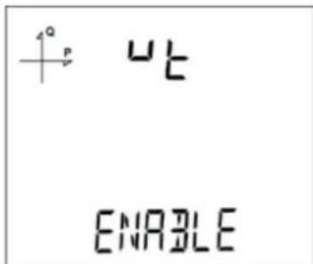
- By using UP/DOWN buttons, select Enable or Disable indicating whether you use a voltage transformer on your system.
- If Passive option is selected, the steps where Secondary and Primary values are entered will be skipped.
- Press the SET button and go to the next step.
5.2.1.4. VT Secondary Value

- Enter the secondary value of your VT by using SET and UP/DOWN buttons.
- You can approve a digit value by pressing the SET button.
- After entering the necessary value, Press the SET button and go to the next step.
5.2.1.5. VT Primary Value
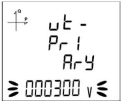
- Enter the primary value of your VT by using SET and UP/DOWN buttons.
- You can approve a digit value by pressing the SET button.
- After entering the necessary value, Press the SET button and go to the next step.
5.2.1.6. CT Secondary Value Selection

- By using UP/DOWN buttons, select your CT secondary value type as 1A or 5A.
- After selecting the necessary value, Press the SET button and go to the next step.
5.2.1.7. CT Primary Value

- Enter the primary value of your CT between 1 and 9999 A by using SET and UP/DOWN buttons.
- You can approve a digit value by pressing the SET button.
- After entering the necessary value, Press the SET button and go to the next step.
5.2.1.8. 5.2.1.8. Nominal Frequency Value Selection

- By using UP/DOWN buttons, select your nominal network frequency as 50Hz or 60Hz.
- After selecting the necessary value, Press the SET button and go to the next step.
5.2.1.9. Nominal Operating Voltage Value

-
Enter the nominal operating voltage value between 25 and 300 V by using SET and UP/DOWN buttons.
-
You can approve a digit value by pressing the SET button.
-
After entering the necessary value, Press the SET button and go to the next step
5.2.1.10. Time Zone Setting

- By using UP/DOWN buttons, you can select the time zone information about the device location between -12:00 and +12:00 in 30 minute intervals.
- After selecting the necessary value, Press the SET button and go to the next step.
5.2.1.11. Date Setting

- Enter the date by using SET and UP/DOWN buttons.
- You can approve a digit value by pressing the SET button.
- After entering the correct date, Press the SET button and go to the next step.
5.2.1.12. Hour Setting

- Enter the time by using SET and UP/DOWN buttons.
- After entering the correct date, Press the SET button and go to the next step.
5.2.1.13 ENTBUS Mode
This setting option is available on devices with an Ethernet connection.

- Press the SET button while on the Ethernet Entbus screen.
- Press the SET button while on the Entbus screen. Set the desired ON and OFF options by using the UP and DOWN buttons and confirm with the SET button.
- Do not forget to save your settings when you exit the menu with the BACK button.
NOTE: If the Entbus mode is set to OFF, the device will operate in server mode by accepting connection requests over TCP port.
If Entbus mode is set to ON, in client mode, the server will connect to the set server via TCP port.
5.2.2. Display Settings
Language settings, display contrast and backlight settings are located from the Display Setting section.
5.2.2.1. Language Setting

Messages on the device screen can be viewed in four languages:
- Turkish
- English
3.German
4.French
Note: Please contact your Sales Representative for models in Scandinavian languages (Norwegian, Finnish, Swedish) that can be requested optionally.
5.2.2.2. Backlight Setting

There are three settings for the backlight of the device:
- Always ON
- Always OFF
- Automatic.
When "Automatic" option is selected, the backlight turns on after a button is pressed and turns off after no button is pressed for 3 minutes.
5.2.2.3. Display Contrast Setting
Display contrast of the device can be selected between 0 and 15. The factory default value is 3.
- Select Contrast option from the Settings/Display and press SET button.
• Current contrast option will start blinking. Select one of the options and press SET button. - When exiting from the menu with the BACK or ESC button, don't forget to save the changes.

5.2.3. Time Settings
5.2.3.1. Hour Setting
The time of the device's RTC module can be set in hours, minutes and seconds.
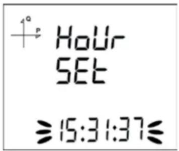
To set the time, follow these steps:
- Press the SET button while on Setup Clock screen.
- Press the SET button on the Hour Set screen, which is the first option.
- While on Hour Set screen, Press the SET button and select the hour part.
- Hour value will start to blink
- Adjust the hour by using UP/DOWN buttons.
- Press the SET button to switch to the minute value. Repeat these steps for minutes and seconds parts.
7 Press the SET button to switch to the minute value. Repeat these steps for minutes and seconds parts
5.2.3.2. 5.2.3.2. Date Setting

To set the date, follow these steps:
- Press the SET button on the Date Set screen.
- Press the SET button. Adjust the day with UP/DOWN buttons
- Press the SET button. Adjust the month with UP/DOWN buttons.
- Press the SET button. Adjust the year with UP/DOWN buttons.
5 When exiting from the menu with the BACK or ESC button, don't forget to save the changes.
5.2.3.3. Time Zone Setting

- Press the SET button while "Clock Time Zone" is displayed
- Selected Time Zone screen is displayed.
- Enter the menu by pressing the SET button
- Select your time zone in 30 minutes increments by using UP/DOWN buttons.
- Press the SET button after you're finished with selection.
- When exiting from the menu with the BACK or ESC button, don't forget to save the changes.
5.2.3.4. DST Mode Setting

- Press the SET button while Clock DST Mode screen is displayed.
- Daylight Save screen is displayed.
- Press the SET button and select one of EUROPE, USA, MANUEL and DISABLE options.
- If you select MANUEL option; you will have to enter month, week, day and hour for the start of DST in that order.
- After finishing the DST Start settings; you will have to enter month, week, day and hour for the end of DST in that order.
- After selecting your DST setting, press the SET menu and exit from this menu.
- When exiting from the menu with the BACK or ESC button, don't forget to save the changes.
5.2.4. RS-485 Communication Settings
5.2.4.1. RS-485 Address Setting


- Select Address option from the Settings/RS-485 and press SET button.
- Current address option will start blinking. You can browse between digits with SET and BACK buttons. Select an address between 1 and 247 and press SET button.
- When exiting from the menu with the BACK or ESC button, don't forget to save the changes.
5.2.4.2. RS-485 Baud Rate Setting

RS-485 communication speed of the device can be set to one of the following options:
- 2400 bps
- 4800 bps
- 9600 bps
- 19200 bps
- 38400 bps
- 57600 bps
-
115200 bps
-
Press the SET button while on RS-485 baud rate screen.
- Press the SET button to start selecting the baud rate value.
- Select your communication speed by using UP/DOWN buttons.
- When exiting from the menu with the BACK button, don't forget to save the changes.
5.2.4.3. RS-485 Parity Setting

Communication parity of the device can be set as Odd, Even or None. Factory default setting for parity is NONE.
- Press the SET button while on RS-485 parity screen.
- Press the SET button to start selecting the parity option.
- Select your parity by using UP/DOWN buttons.
- When exiting from the menu with the BACK button, don't forget to save the changes.
5.2.5 Ethernet Communication Systems
5.2.5.1. DHCP Mode


DHCP mode indicates that your device will get its IP address via a DHCP server for the ethernet connection.
Set the DHCP mode to ON or OFF according to the network infrastructure to which the analyzer is connected. If DHCP is set to ON, the device will receive the IP address automatically determined by the network server. If DHCP is set to OFF, the device will try to get the IP entered in the 5.2.4.2. Ethernet IP Address setting screen from the network server.
- While on the Setup Ethernet screen, press the SET button.
- Press the SET button while on the Ethernet DHCP MOD screen, which is the first page.
- Press the SET button while on the DHCP screen. Set the desired ON and OFF options by using the UP and DOWN buttons and confirm with the SET button.
- not forget to save your settings when exiting the menu with the BACK button.
5.2.5.2. Ethernet IP Address
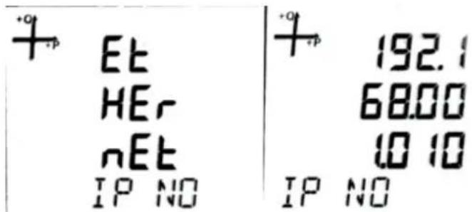
Ethernet IP address shows the IP address that the device will use for the ethernet connection when DHCP is not enabled. If DHCP Mode is set to Off, Static IP must be entered on this screen. The device will try to get the IP entered on this screen from the network server.
The entered IP address appears on the monitoring screen with the IP shortcut on the device.
- While on the Ethernet IP NO screen, press the SET button.
- In the IP NO screen, use the UP and DOWN button to enter the desired value and confirm with the SET button.
- Do not forget to save your settings when exiting the menu with the BACK button.
5.2.5.3. Subnet Mask Address


The subnet mask address shows the network address which the device is connected.
- While on the Ethernet SUBNET M screen, press the SET button.
- On the SUB MASK screen, use the UP and DOWN buttons to enter the desired value and confirm with the SET button.
- Do not forget to save your settings when exiting the menu with the BACK button.
5.2.5.4. Gateway Address


The gateway address shows the address of the modem or gateway that the device is connected to the internet.
- Press the SET button while on the Ethernet Gateway screen.
- On the Gateway screen, use the UP and DOWN buttons to enter the desired value and confirm with the SET button.
- Do not forget to save your settings when exiting the menu with the BACK button.
5.2.5.5. DNS (DNS-1) Address

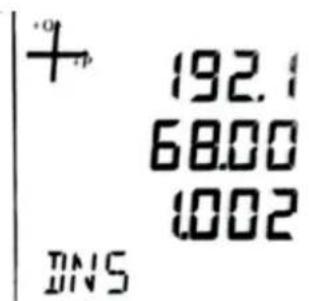
DNS-1 address is the address of the DNS (Domain Name System) server to be used to resolve the server address to be connected when the device is in client mode.
- While on the Ethernet DNS 1 screen, press the SET button.
- On the DNS screen, use the UP and DOWN button to enter the desired value and confirm with the SET button.
- Do not forget to save your settings when exiting the menu with the BACK button.
5.2.5.6. Alternate DNS (DNS-2) Address

DNS-2 address is the address of the backup (alternative) DNS server to be used to resolve the server address to be connected when the device is in client mode.
-
Press the SET button while on the Ethernet DNS 2 screen.
-
Enter the desired value by using the UP and DOWN buttons on the DNS-ALTR screen and confirm with the SET button.
-
Do not forget to save your settings when exiting the menu with the BACK button.
5.2.5.7. Ethernet Port Number

Ethernet port address refers to the port number to be used for Modbus TCP in server mode.
- While on the Ethernet Port No screen, press the SET button.
While on the TCP Port No screen, use the UP and DOWN button to enter the desired value and confirm with the SET button.
- Do not forget to save your settings when exiting the menu with the BACK button.
5.2.5.8. Timeout

If the device is operating in server mode, the connection of the device to the relevant socket will be closed if there is no data exchange.
If the device is operating in client mode, the device will reconnect to the set server in case of no data exchange.
- Press the SET button while on the Ethernet Timeout screen.
- On the Timeout screen, use the UP and DOWN buttons to enter the desired value and confirm with the SET button.
- Do not forget to save your settings when exiting the menu with the BACK button.
5.2.5.9. Entbus Mode

If the Entbus mode is set to OFF, the device will operate in server mode by accepting connection requests over TCP port.
If the Entbus mode is set to ON, in client mode, the server will connect to the set server via TCP port.
-
While on the Ethernet Entbus screen, press the SET button.
-
Press the SET button while on the Entbus screen. Set the desired ON and OFF options by using the UP and DOWN buttons and confirm with the SET button.
-
Do not forget to save your settings when exiting the menu with the BACK button.
5.2.5.10 Server Address
It is the server address that was set when the device was operating in client mode. This setting can only be made via communication.
5.2.5.11 Server TCP Port
It is the port number to connect to the server address set when the device is operating in client mode. This setting can only be made via communication.
5.2.6 Input Parameter Settings
When an Analog Input or Digital Input module is connected to the device, these menus become active.
The number of appearing menus depends on how many inputs are available on the connected module.
- Digital Input: When this option is selected, the device detects the logic level on the input.

- Generator Input: When this option is selected, the device records the energy to the generator register depending on the input state.
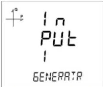
- Pulse Input: When this option is selected, the device can count the pulses that occur on the input. It can display the pulse count on monitoring screens under "Pulse Cntr C-1" section.
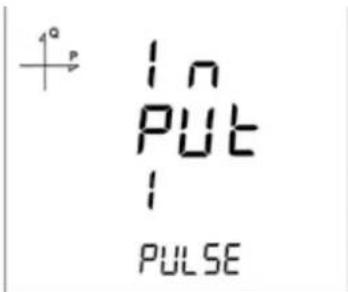
a. Pulse Width Setting

For devices with pulse counting feature, the minimum time necessary for the pulse counting can be selected from following options:
• 40 milliseconds
- 60 milliseconds
• 200 milliseconds
- 80 milliseconds
- 300 milliseconds
• 100 milliseconds
• 400 milliseconds
• 150 milliseconds
- 500 milliseconds
5.2.7 Output Parameter Settings
When an output or input/output module is connected to the device, the purpose of the output is selected from this menu.
The number of appearing menus depends on how many outputs are available on the connected module.
Digital output of the device can be used for one of the following applications:
- Output as Pulse: When this option is selected, the device creates output pulses depending on selected value of active or reactive energy consumption.

- Output as Alarm: When this option is selected, the output changes from logic-1 to logic-0 if the selected parameter exceeds or is below the limit value.
When the alarm condition is resolved, output returns to logic-1.

- Output as Remote Control: When this option is selected, the user can change the output of the device from logic-1 to logic-0 remotely via RS-485 communication.
The remote output can be changed with the corresponding Modbus register address 0x0A. In this way, its output can be used to remotely switch a circuit on and off.

5.2.8. Recording Settings
The following parameters can be recorded to the internal memory of the device in adjustable time intervals. Afterwards, the recorded values can be remotely viewed:
- Load Profile 4. Powers
- Voltages 5. THD values
- Currents
5.2.9. Selecting Parameter to Be Recorded
The parameter to be recorded to the internal memory is selected as following:
5.2.9.1 Load Profile Settings

- Press the SET button while Log Setup-Load Profile is displayed.
- Current option is displayed. Press the SET button again.
- Finish the selection by pressing the SET button.
- When exiting from the menu with the BACK or ESC button, don't forget to save the changes.
5.2.9.2 Voltage Settings

- Press the SET button while Log Setup-Voltages is displayed.
- Current option is displayed. Press the SET button again.
- Select Active or Passive with UP/DOWN buttons. Press the SET button.
- Finish the selection by pressing the SET button.
- When exiting from the menu with the BACK or ESC button, don't forget to save the changes.
5.2.9.3 Current Settings

- Press the SET button while Log Setup-Currents is displayed.
- Current option is displayed. Press the SET button again.
- Select Active or Passive with UP/DOWN buttons. Press the SET button.
- Finish the selection by pressing the SET button.
- When exiting from the menu with the BACK or ESC button, don't forget to save the changes.
- Press the SET button while Log Setup-Currents is displayed.
- Current option is displayed. Press the SET button again.
- Select Active or Passive with UP/DOWN buttons. Press the SET button.
- If you select Active option, recording time interval selection will be active.
- The recording interval appears as 60 seconds.
- Finish the selection by pressing the SET button.
- When exiting from the menu with the BACK or ESC button, don't forget to save the changes.
5.2.9.5 THD Settings

- Press the SET button while Log Setup-THD is displayed.
- Current option is displayed. Press the SET button again.
- Select Active or Passive with UP/DOWN buttons. Press the SET button.
- If you select Active option, recording time interval selection will be active.
- At this stage, press the SET button again. The recording interval appears as 60 seconds.
- Finish the selection by pressing the SET button.
- When exiting from the menu with the BACK or ESC button, don't forget to save the changes.
5.2.9.6 Activating Recording Function

To activate the recording function for any of the settings, select "ACTIVE" for any setting. At this point, recording interval will be selected. It can be selected as one of the following options:
- 60 seconds
2.300 seconds
3.600 seconds - 900 seconds
- 1200 seconds
- 1800 seconds
- 3600 seconds
5.2.9.7. Reading the Records via Modbus
There are two options for accessing the records via Modbus.
5.2.9.8. Accesing the records according to time
For this method, the date of the record to be accessed is entered in UNIX time format to the Modbus addresses starting from 21100. There are 5 address fields. These addresses are for Load Profile, Voltage, Current, Power and THD in that order. The device finds the record closest to the entered date and writes the index belonging to this record to the related index registers. When the user writes this index to the index register at the bottom of the tables at register addresses 23000, 24000, 25000 etc., the details of the entered register will be accessible on the same tables.
5.2.9.9. 5.2.9.9. Accesing the records according to index
For this method, the user writes the record index number to the index register at the bottom of the tables at register addresses 23000, 24000, 25000 etc., the details of the entered register will be accessible on the same tables.
5.2.10. Pulse Input Settings
5.2.10.1. Activating Pulse-1 Input
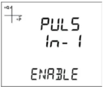
- Press the SET button while SETUP-PULSE IN is displayed.
- Select the input that you want to activate with UP/DOWN buttons and press the SET button.
- Select ENABLE or DISABLE with UP/DOWN buttons and press the SET button.
- When exiting from the menu with the BACK or ESC button, don't forget to save the changes.
5.2.10.2. Activating Pulse-2 Input

- Press the SET button while SETUP-PULSE IN is displayed.
- Select the second input with UP/DOWN buttons and press the SET button.
- Select ENABLE or DISABLE with UP/DOWN buttons and press the SET button.
- When exiting from the menu with the BACK or ESC button, don't forget to save the changes.
5.2.10.3. Selecting Pulse-1 Ratio

- Press UP button while PULSE IN-1 Enable is displayed.
- This value indicates for how many incoming pulses the device will increase the pulse counter. Select this value as displayed above.
- Exit from the menu when selection is complete.
- When exiting from the menu with the BACK or ESC button, don't forget to save the changes.
5.2.10.4. Selecting Pulse-2 Ratio

- Press UP button while PULSE IN-2 Enable is displayed.
- This value indicates for how many incoming pulses the device will increase the pulse counter. Select this value as displayed above.
- Exit from the menu when selection is complete.
- When exiting from the menu with the BACK or ESC button, don't forget to save the changes.
5.2.11. Pulse Output Settings
5.2.11.1. Pulse Output According to Active Energy


When Pulse Output is selected, the device can create pulses for import or export active energy according to the increments listed below.
Import or export energy can be selected as the source.
- 1 Wh • 10 kWh
- 10 Wh • 100 kWh
- 100 Wh • 1 MWh.
- 1 kWh
5.2.11.2. Pulse Output According to Reactive Energy

![1° PULS OUT1 PAR-A [+ER Q1]](/content/2026/06/1362324/images/6d2307cc00bd852849dad4866e5029d273dec93da3be7fac82905a34610b361c.jpg)

![PUL5 OUT1 PAR-A [-ER Q3]](/content/2026/06/1362324/images/1246f0df672828771e68e9f15110a0c9995b888eba5536a53008c7a861ffbdb2.jpg)

When Pulse Output is selected, the device can create pulses for import or export reactive energy according to the increments listed below.
Reactive energy values from Q1, Q2, Q3 and Q4 quadrants can be used as source.
- 1 VArh 8. 1 kVArh 11. 1 MVArh
- 10 VArh 9. 10 kVArh
- 100 VArh 10. 100 kVArh
5.2.11.3. Pulse Output Duration Settings
The duration during the pulse stays at logic-1 level is entered here.
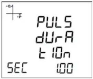
5.2.11.4. Pulse Output Inactive Time Setting
The duration during the pulse stays at logic-0 level is entered here.

5.2.12. Operating Hours Settings
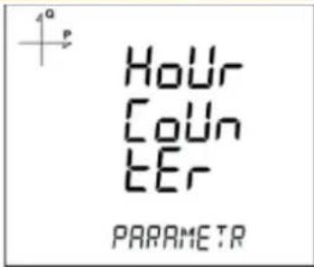
Parameter is selected from the Hour Counter menu. If you select VLN for example, display changes as following

Afterwards, the limit value is selected. When the parameter exceeds this limit value, hour counter will start.
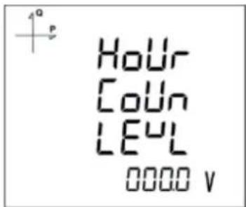
Exit from the menu when selection is complete.
When exiting from the menu with the BACK or ESC button, don't forget to save the changes.
5.2.13. Alarm Settings
Different parameters can be assigned to the 4 alarms that the device has. Following operations are described for a single alarm but they are the same for the other 3 alarms.
5.2.13.1. Activating alarm

Alarm is activated by following these steps:
- Press the SET button while Setup Alarm is displayed.
- While Alarm Enable is displayed, Press the SET button and select ENABLE or DISABLE with UP/DOWN buttons.
- Press the SET button after completing your selection.
- When exiting from the menu with the BACK or ESC button, don't forget to save the changes.
5.2.13.2. Alarm Parameter Selection
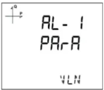
- Press the SET button while Alarm Setup is displayed.
- Find Alarm Parameter by pressing UP/DOWN buttons.
- Enter Alarm Parameter menu by pressing the SET button.
- Select one of the following parameters with UP/DOWN buttons:
a. Phase currents
b. Total Current
c. Current Demand
d. Total Current Demand
e. Active Power
f. Reactive Power
g. Apparent Power
h. Total Active Power
i. Total Reactive Power
j. Total Apparent Power
k. Active Power Demand
I. Apparent Power Demand
m. Total Active Power Demand
n. Total Apparent Power Demand
o. Cos Phi
p. Total Cos Phi
q. Frequency
r. THDV
s. THDU
t. THDI
u. Hour Counter
v. Digital Input
w. Tariffs
x. Phase-Neutral Voltage
y. Phase-Phase Voltage
- Press the SET button after completing your selection.
5.2.13.3. Alarm Operation Type Selection
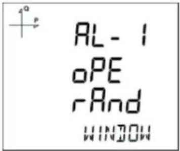
- Press the SET button to select the alarm operation type.
- Select one of the following options:
a. In window
b. Out window
c. Lower than
d. Higher than
- When "In window" or "Out window" options are selected, high and low limit values are entered.
- When "Higher than" option is selected, a high limit value is entered. When "Lower than" option is selected, a low limit value is entered.
- When exiting from the menu with the BACK or ESC button, don't forget to save the changes.
5.2.13.4. High Alarm Limit Setting
A high limit for the alarm is entered in this menu.
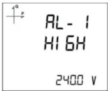
- While Alarm Enable is selected, find Alarm High menu with UP/DOWN buttons
- Press the SET button. Enter the high alarm limit with UP/DOWN buttons.
- Press the SET button after completing your selection.
- Alarm parameters can be saved for 4 different alarms separately.
- When exiting from the menu with the BACK or ESC button, don't forget to save the changes.
5.2.13.5. Low Alarm Limit Settings
A low limit for the alarm is entered in this menu.

- While Alarm Enable is selected, find Alarm Low menu with UP/DOWN buttons.
- Press the SET button. Enter the low alarm limit with UP/DOWN buttons.
- Press the SET button after completing your selection.
- Alarm parameters can be saved for 4 different alarms separately.
- When exiting from the menu with the BACK or ESC button, don't forget to save the changes.
5.2.13.6. Alarm Hysteresis Setting
A hysteresis value for the alarm is entered in this menu.
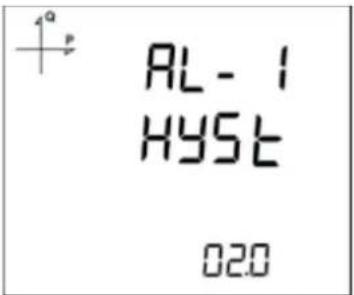
- While Alarm Enable is selected, find Alarm Hyst menu with UP/DOWN buttons.
- Press the SET button. Enter the hysteresis value for the alarm as % with UP/DOWN buttons.
- Press the SET button after completing your selection.
- Alarm parameters can be saved for 4 different alarms separately.
- When exiting from the menu with the BACK button, don't forget to save the changes.
5.2.13.7. Alarm Delay Times Setting
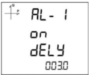
- Alarm activation delay is determined by pressing the SET button after the alarm hysteresis screen.
- The delay time in seconds is adjusted by pressing the UP and DOWN buttons and switching between digits with the SET button.
- ALARM is generated when the alarm source specified in the above items exceeds the limit for the time set at this stage.
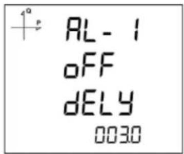
- By pressing the DOWN button, the alarm off time is also determined on the next screen.
- The minimum time to clear the alarm is selected on the off delay screen that appears when the SET button is pressed.
- Set the desired value in seconds with the UP and DOWN buttons.
5.2.14. Tariff Settings
5.2.14.1. Activating Tariffs
Press the SET button when Tariffs, under the Setup Menu is displayed. The following screen will be displayed:

You can activate tariff function of the device by pressing the SET button again and using DOWN button.

Do not forget to save the changes while leaving the menu with BACK or ESC button. Time settings of the Tariffs are entered with serial communication, according to Modbus Table.
5.2.15. Reset Settings
Users can reset the minimum, maximum, demand and log records that the device has stored.
5.2.15.1. Resetting Maximum Values

-
Select Maximum from the Reset menu and press the SET button.
-
Press the SET button while "Reset High" is displayed and select YES option with UP/DOWN buttons.
-
Complete the entry with the SET button.
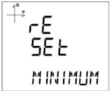
5.2.15.2. Resetting Minimum Values
-
Select Minimum from the Reset menu and press the SET button.
-
Press the SET button while "Reset Low" is displayed and select YES option with UP/DOWN buttons.
-
Complete the entry with the SET button.
5.2.15.3. Resetting Demand Values

- Select Demand records from the Reset menu and press the SET button.
- In the Reset High section that appears on the screen, select the Yes option for the reset process by using the up/down buttons.
- Complete the entry with the SET button.
5.2.15.4. Resetting Maximum Demand Values

- Select Maximum Demand from the Reset menu and press the SET button.
- Press the SET button while "Reset DE" is displayed and select YES option with UP/DOWN buttons.
- Complete the entry with the SET button.
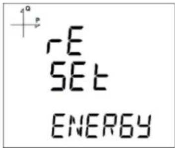
5.2.15.5. Resetting Energy Values
-
Select Energy recordings from the Reset menu and press the SET button.
-
In the Reset Energy section that appears on the screen, select the Yes option for the reset process by using the UP/DOWN buttons.
-
Complete the entry with the SET button.
5.2.15.6. Resetting Generator Energy

-
Select Gen Enrg recordings from the Reset menu and press the SET button.
-
In the Reset GenE section that appears on the screen, select the Yes option for the reset process by using the UP/DOWN buttons.
-
Complete the entry with the SET button.
5.2.15.7. Resetting Tariff Energy Values
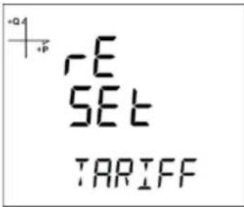
- Select Tariff from the Reset menu and press the SET button.
-
Press the SET button while "Reset Tariff" is displayed and select YES option with UP/DOWN buttons
-
Complete the entry with the SET button.
5.2.15.8. Resetting Pulse Counter Values
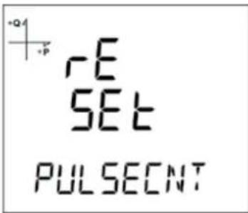
- Select PULSE CNT recordings from the Reset menu and press the SET button.
- In the Reset PULS section that appears on the screen, select the Yes option for the reset process by using the UP/DOWN buttons.
- Complete the entry with the SET button.
5.2.15.9. Resetting Hour Counter Values

- Select HourCntr recordings from the Reset menu and press the SET button.
-
In the Reset HoUr section that appears on the screen, select the Yes option for the reset process by using the UP/DOWN buttons.
-
Complete the entry with the SET button.
5.2.16. System Settings
5.2.16.1. PIN Code Activation
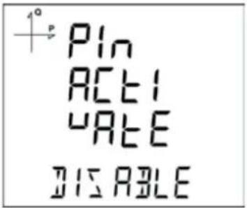
Whether or not a password is required to enter the settings menu is provided by the settings made in this section.
- Press the SET button on the Pin Act screen in the system menu.
- When you press the SET button while "Pin Acivate" is displayed, you will have to enter the 4 digit factory default pin.
- Select the default pin digits with UP/DOWN buttons and confirm the digit with SET button.
- After entering the correct default pin, you can change Disable option to Enable. Press the SET button after selecting Enable.
- Factory default setting PIN is 1234.
5.2.16.2. Changing the PIN Code

- Press the SET button on the Pin Chng screen in the system menu.
- While "PIN CHAnGE" is displayed, press the SET button.
- Enter the old PIN digit by digit with UP/DOWN buttons.
- If you enter the old pin incorrectly, "ERROR" will be displayed.
- If "ERROR" is displayed, press the SET button and enter the pin again correctly.
- If you enter the old pin correctly, "PIN CHnGnE" will be displayed.
- Enter your new 4 digit PIN and press the SET button.
- Enter your new 4 digit pin again and press the SET button.
- After entering the new pin correctly twice, "PIN CHAnGE CHANGED" will be displayed.
- You can use your new PIN next time you enter the Setup Menu.
5.2.16.3. Resetting to Factory Settings

- To reset the device to factory settings, press the SET button while "SYSTEM FACT RST" is displayed.
- While "FACtorY rSET" is displayed, pin code must be entered when the SET button is pressed.
- Enter your PIN code with UP/DOWN buttons. Press the SET button.
- If the PIN is entered correctly, "No" will be displayed at the bottom of the screen.
- Press the SET button and change the "No" option to "Yes" with UP/DOWN buttons.
- When exiting from the menu with the BACK button, don't forget to save the changes.
- After exiting the Menu device will restart itself and turn back to the default settings. All log records and setting data as a result of measurements are deleted. After the restarting process device version will be displayed and device installation process will start.
- After completing the settings, voltage measurement screen will be displayed.
5.2.16.4. Displaying Module Information

You can access the information of the module installed in the system from this screen. When the SET button is pressed on the screen shown above, the information about the module appears as in the screen below

5.2.16.5. Displaying Software and Hardware Version


To learn the software and hardware version of the system, follow the steps below:
- Press the SET button while the system is on the Soft VER screen.
- The software version of the system appears on the bottom line of the screen.
- When the SET button is pressed again, the hardware version of the system is displayed with the phrase Hhard VerSlon.
5.2.16.6. Displaying Serial Number of the Device

- In the system menu, press the SET button while on the Serial N screen.
- The serial number of the device appears on the screen as 8 digits with the expression SERIAL no.
5.2.17. Analog Output Settings
When an analog output module is connected to the device, the purpose of the output is selected from this menu.
5.2.17.1. Analog Output-1 Type Settings


- Press the SET button while Analog O-1 Type is displayed.
-
The selected option starts to blink.
-
Select one of 0-5V, 0-10V, -5 \~ 5V and -10 \~ 10V 0-20mA, 0-24mA ve 4-20mA options with UP/DOWN buttons.
-
After completing your selection, press the SET button.
-
When exiting from the menu with the BACK or ESC button, don't forget to save the changes.
5.2.17.2. Analog Output-1 Parameter Settings

While there is Analog O-1 Parameter on the screen, press the SET button.
- The selected option starts to blink.
- Select one of the following options with the Up/Down buttons.
a. VLN1,
b. VLN2,
c. VLN3,
d. VLN4,
e. VLL1,
f. VLL2,
g. VLL3,
h. IL1,
i. IL2,
j. IL3,
k. IL4,
I. IN,
m. IL1 DEMAND
n. IL2 DEMAND,
o. IL3 DEMAND,
p. IL4 DEMAND,
q. IN DEMAND,
r. P1,
s. P2,
t. P3,
u. Q1,
v. Q2,
w. Q3,
x. S1,
y. S2,
z. S3,
aa. Total P,
ab. Total Q,
ac. Total S,
ad. Cos Phi-1,
ae. Cos Phi-2,
af. Cos Phi-3,
ag. Total Cos Phi,
ah. Frekans,
ai. VLN4,
aj. IL4,
ak. Total I,
al. Total I Demand,
am. Total P Demand,
an. Total S Demand,
ao. Total VLN,
ap. Total VLL.
- After completing your selection, press the SET button.
- Do not forget to save the changes, when you exit from the menu with BACK or ESC button.
5.2.17.3. Analog Output-1 High Value Settings

- Press the SET button while Analog O-1 High is displayed.
- The selected option starts to blink.
- Enter your high value with UP/DOWN buttons.
- After entering your value, press the SET button.
- When exiting from the menu with the BACK or ESC button, don't forget to save the changes.
5.2.17.4. Analog Output-1 Low Value Settings

- Press the SET button while Analog O-1 LOV is displayed.
- The selected option starts to blink.
- Enter your low value with UP/DOWN buttons.
- After entering your value, press the SET button.
- When exiting from the menu with the BACK or ESC button, don't forget to save the changes.
Example
By going to the settings menu of the device, the following settings should be made in order.
Type: 0-20 mA
Parametre: VLN1
Low (Low value): 90 V High (High Value): 300 V
According to the settings above, analog output will be 0 mA when VL1 value is 90 V or lower and it will be 20 mA when VL1 value is 300 V or larger.
When VL1 value is 200 V;
$$ I _ {\text { cikis }} = \frac {(2 0 - 0) \times (2 2 0 - 9 0)}{(3 0 0 - 9 0)} = 1 2, 3 8 m A $$
the output value is calculated as seen above
5.2.17.5. Analog Output-2 Type Settings
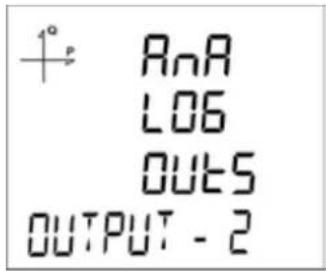
- Press the SET button while Analog O-2 Type is displayed.
-
The selected option starts to blink.
-
Select one of 0-5V, 0-10V, -5 \~ 5V, -10 \~ 10V, 0-20mA, 0-24mA ve 4-20mA options with UP/DOWN buttons
- After completing your selection, press the SET button.
- When exiting from the menu with the BACK or ESC button, don't forget to save the changes.
5.2.17.6. Analog Output-2 Parameter Settings
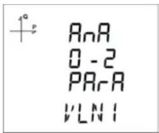
-
Press the SET button while Analog O-2 PArA is displayed.
-
The selected option starts to blink.
- Select one of the following parameters with UP/DOWN buttons.
a. VLN1,
b. VLN2,
c. VLN3,
d. VLN4,
e. VLL1,
f. VLL2,
g. VLL3,
h. IL1,
i. IL2,
j. IL3,
k. IL4,
I. IN,
m. IL1 DEMAND
n. IL2 DEMAND,
o. IL3 DEMAND,
p. IL4 DEMAND,
q. IN DEMAND,
r. P1,
s. P2,
t. P3,
u. Q1,
v. Q2,
w. Q3,
x. S1,
y. S2,
z. S3,
aa. Total P,
bb. Total Q,
cc. Total S,
dd. Cos Phi-1,
ee. Cos Phi-2,
ff. Cos Phi-3,
gg. Total Cos Phi,
hh. Frekans,
ii. VLN4,
jj. IL4,
kk. Total I,
II. Total I Demand, mm)
mm. Total P Demand,
nn. Total S Demand,
oo. Total VLN,
pp. Total VLL
- After completing your selection, press the SET button.
- When exiting from the men with the BACK or ESC button, do not forget to save the changes.
5.2.17.7. Analog Output-2 High Value Settings

- Press the SET button while Analog O-2 HIGH is displayed.
- The selected option starts to blink.
- Enter your high value with UP/DOWN buttons.
- After entering your value, press the SET button.
- When exiting from the menu with the BACK or ESC button, don't forget to save the changes.
5.2.17.8. Analog Output-2 Low Value Settings

- Press the SET button while Analog O-LOV is displayed.
- The selected option starts to blink.
- Enter your low values with UP/DOWN buttons.
- After entering your value, press the SET button.
- When exiting from the menu with BACK or ESC button.
5.3. Reporting Screen
When the ESC button of the device is pressed for 3 seconds, reports of recorded events are displayed on the screen.
255 events can be recorded on the device.
Recorded event types are: Initial energization, short interruption (<3s), long interruption, alarm, setting change, time change and reset.
You can switch between the recorded events with the UP/DOWN buttons

Events are listed in order of occurrence.
Record 1 is listed as the newest report, and record 255 as the oldest report.

After pressing the SET button, details of the event can be displayed in the following order;
-
Starting date,
-
Starting time,
-
Ending date,
-
Ending time,
-
Duration,
-
Parameter,
-
Source of the event,
-
Value that caused the event.
If no button is pressed for 60 seconds, the device returns to measuring screen.
6. TECHNICAL FEATURES AND APPENDIX
| Operating Voltage (Un) | 50 - 270 ± %10 VAC/DC (24-60 VAC/DC for MPR-4X-D) |
| Operating Frequency (f) | 50-60 Hz |
| Supply Input Burden | <6 VA (with Module <10VA) |
| Measuring Input Burden | <0,5 VA |
| Measuring Voltage Input (Vin) | 5 - 300 VAC 45-65 Hz (L-N)5 - 480 VAC (L-L) |
| Measuring Current Input (lin) | 0,05 - 5,5 AAC (MPR-4X and MPR-4X-OG/OGT)100-500 mV (MPR-4X-PM) |
| Measuring Power Range 0...9999 MW | |
| Measuring Energy Range | 9999999.9 k/M (Wh, VArh) |
| Measuring Accuracy Classes | |
| Voltage | %0,5 (%0,2 for MPR-4X-0,5) |
| Current | %0.5 (%0,2 for MPR-4X-0,5) |
| Frequency | %0.1 |
| cosφ | %0.2 |
| Active Power and Active Energy | %1 (%0,5 for MPR-4X-0,5) |
| Reactive Power and Reactive Energy | %2 (%1 for MPR-4X-0,5) |
| Sampling Frequency | 128 sample / period |
| Current Transformer Maximum Primer Value | 9999 A |
| Voltage Transformer Maximum Primer Value | 999.9 kV |
| Demand Period | 1-60 dk. adjustable |
| Communication (Isolated) | RS-485 Modbus RTUEthermet Modbus TCP (for MPR-4XSE) |
| Baud Rate | 2400 - 115200 bps |
| Address | 1 - 247 |
| Parity | None,Even, Odd |
| Stop Bit | 1 |
| Max. Communication Distance | 1200 m (RS-485 with Modbus signal strengthening) |
| Internal Memory | 16 MB |
| Relay Outputs (with module) | 2 NO, 5 A/1250 VA |
| Pulse Outputs (with module) | 5-30 VAC/DC |
| Pulse Width (interval) | t-ON = ≥ 30 ms |
| Time between two pulse | t-OFF = ≥ 30 ms |
| Transition Duration | t-T = ≤ 5 ms |
| Digital Inputs | 5-30 VAC/DC |
| Analog Voltage Outputs (2 pcs, with module) | 0-10 V, 0-5 V, ±5 V, ±10 V |
| Analog Current Outputs (2 pcs, with module) | 0-20 mA, 0-24 mA, 4-20 mA |
| Connection Type | 3F4T, 3F3T, ARON, 3F4T balanced, 3F3T balanced |
| Detailed Harmonic Measurement | 2 - 51. Harmonics (for MPR-47S-X)2. - 31. Harmonics (for MPR-42-OGT) |
| Operating Temperature | -10...+70°C |
| Storage Temperature | -20...+80°C |
| Humidity | Maximum %90 |
| Display | 3,5" Illuminated STN Custom segment LCD |
| Data Logging | Available |
| Data/ Parameter Record | Available (models with internal memory) |
| Real Time Clock (RTC) | Available |
| Tariffs number | 8+1 (generator) |
| Dimensions | 96x96x45 mm (modül ile 96x96x65 mm) |
| Device Protection Class | Double Insulation |
| Front Panel Protection Class | IP51 (IP54 optionel) |
| Terminals Protection Class | IP20 |
| Enclosure Material | Nonflammable, UL94 V-0 type plastic |
| Mounting | Front Panel Mounting |
| Cable Thickness For Voltage Connection | max. 2.5 mm^2 |
| Cable Thickness For Current Connection | max. 2.5 mm^2 |
| Cable Thickness For RS-485 Connection | max. 1.5 mm^2 |
ENTES Elektronik Cihazlar Imalat ve Ticaret A.S.
Adr: Dudullu OSB; 1. Cadde; No:23 34776
Ümraniye - İSTANBUL / TÜRKİYE
Tel: +90 216 313 01 10 Faks: +90 216 314 16 15
E-mail: iletisim@entes.com.tr Web: www.entes.com.tr
- INDEX
- SAFETY AND WARNINGS.... 3
- OPERATING CONDITIONS 4
- INTRODUCTION 5
- CONNECTION 12
- OPERATING INSTRUCTIONS.... 15
- TECHNICAL FEATURES AND APPENDIX 69
- Warning
- Safety
- Warranty
- OPERATING CONDITIONS
- General Features
- Applications
- MPR-4X Series Product
- Overview and Interface
- Terminals
- MPR-4X Series Rear Panel
- MPR-4X-OG/OGT Series Rear Panel
- MPR-4X-PM Series Rear Panel
- Screen
- Button Functions
- ESC button (9) : It has 3 main functions:
- BACK Button (10) : It has 3 main functions:
- Down Button (11): It has 2 main functions:
- Up Button (12) : It has 2 main functions:
- SET Button (13) : It has 3 main functions:
- Terminal Structure
- CONNECTION
- 3P4W (Three Phase Four Wires) Connection
- 3P3W (3 Phase 3 Wires) Connection
- Aron without Neutral Connection
- 3P4W BLN (3 Phase Balanced with Neutral) Connection
- 3P3W BLN (3 Phase Balanced without Neutral) Connection
- Connection Test
- OPERATING INSTRUCTIONS
- Measurement Screens
- Current, Voltage and Frequency Screens
- Power and Power Factor Screens
- Energy and Time Screen
- THD and Harmonics Screens (MPR-46X, MPR-47X ve MPR-42-OGT)
- Minimum, Maximum and Demand Screens
- Ethernet Parameter Displaying Screens (MPR-4XSE)
- Setup Screen
- Accesing the Programming Menu
- Device Installation Settings
- Language Setting
- Connection Type Setting
- Voltage Transformer Usage
- VT Secondary Value
- VT Primary Value
- CT Secondary Value Selection
- CT Primary Value
- 5.2.1.8. Nominal Frequency Value Selection
- Nominal Operating Voltage Value
- Time Zone Setting
- Date Setting
- Hour Setting
- ENTBUS Mode
- Display Settings
- Language Setting
- Backlight Setting
- Display Contrast Setting
- Time Settings
- Hour Setting
- 5.2.3.2. Date Setting
- Time Zone Setting
- DST Mode Setting
- RS-485 Communication Settings
- RS-485 Address Setting
- RS-485 Baud Rate Setting
- RS-485 Parity Setting
- Ethernet Communication Systems
- DHCP Mode
- Ethernet IP Address
- Subnet Mask Address
- Gateway Address
- DNS (DNS-1) Address
- Alternate DNS (DNS-2) Address
- Ethernet Port Number
- Timeout
- Entbus Mode
- Server Address
- Server TCP Port
- Input Parameter Settings
- Output Parameter Settings
- Recording Settings
- Selecting Parameter to Be Recorded
- Load Profile Settings
- Voltage Settings
- Current Settings
- THD Settings
- Activating Recording Function
- Reading the Records via Modbus
- Accesing the records according to time
- 5.2.9.9. Accesing the records according to index
- Pulse Input Settings
- Activating Pulse-1 Input
- Activating Pulse-2 Input
- Selecting Pulse-1 Ratio
- Selecting Pulse-2 Ratio
- Pulse Output Settings
- Pulse Output According to Active Energy
- Pulse Output According to Reactive Energy
- Pulse Output Duration Settings
- Pulse Output Inactive Time Setting
- Operating Hours Settings
- Alarm Settings
- Activating alarm
- Alarm Parameter Selection
- Alarm Operation Type Selection
- High Alarm Limit Setting
- Low Alarm Limit Settings
- Alarm Hysteresis Setting
- Alarm Delay Times Setting
- Tariff Settings
- Activating Tariffs
- Reset Settings
- Resetting Maximum Values
- Resetting Minimum Values
- Resetting Demand Values
- Resetting Maximum Demand Values
- Resetting Energy Values
- Resetting Generator Energy
- Resetting Tariff Energy Values
- Resetting Pulse Counter Values
- Resetting Hour Counter Values
- System Settings
- PIN Code Activation
- Changing the PIN Code
- Resetting to Factory Settings
- Displaying Module Information
- Displaying Software and Hardware Version
- Displaying Serial Number of the Device
- Analog Output Settings
- Analog Output-1 Type Settings
- Analog Output-1 Parameter Settings
- Analog Output-1 High Value Settings
- Analog Output-1 Low Value Settings
- Example
- Analog Output-2 Type Settings
- Analog Output-2 Parameter Settings
- Analog Output-2 High Value Settings
- Analog Output-2 Low Value Settings
- Reporting Screen
- TECHNICAL FEATURES AND APPENDIX
Brand : ENTES
Model : MPR-47S-D
Category : Analyseur réseau électrique