
MH4 - Audio Mixer SOUNDCRAFT - Free user manual and instructions
Find the device manual for free MH4 SOUNDCRAFT in PDF.


| Product type | Analog mixing console |
| Model | Soundcraft MH4 |
| Number of input channels | 32 mono (mic/line) + 4 stereo line inputs |
| Output busses | 4 subgroups, L/R stereo mix, 4 aux sends |
| Frequency response | 20 Hz – 20 kHz ±0.5 dB |
| Equalization | 4-band EQ with sweepable mid frequencies |
| Phantom power | +48 V global switch |
| Dimensions (W x D x H) | 48.5 x 21.7 x 5.7 inches (123.2 x 55.1 x 14.5 cm) |
| Weight | 75 lbs (34 kg) |
| Power consumption | 200 VA typical |
| Power supply | Internal, 100-240 VAC, 50-60 Hz |
| Input impedance (mic) | 1.5 kΩ |
| Input impedance (line) | 10 kΩ |
| Output impedance | 75 Ω |
| Maximum output level | +22 dBu |
| Maintenance and cleaning | Use dry cloth; avoid solvents; vacuum vents regularly |
| Safety | Ensure proper ventilation; do not expose to moisture; use grounded outlets |
| Spare parts and repairability | Available from authorized Soundcraft service centers; modules can be replaced individually |
Frequently Asked Questions - MH4 SOUNDCRAFT
User questions about MH4 SOUNDCRAFT
0 question about this device. Answer the ones you know or ask your own.
Ask a new question about this device
Download the instructions for your Audio Mixer in PDF format for free! Find your manual MH4 - SOUNDCRAFT and take your electronic device back in hand. On this page are published all the documents necessary for the use of your device. MH4 by SOUNDCRAFT.
USER MANUAL MH4 SOUNDCRAFT
This equipment complies
with the EMC directive
89/336/EEC Environment E1-E4.
93/68/EEC
and LVD 73/23/EEC
For further details contact:
Harman International Industries Ltd.
Cranborne House, Cranborne Road
Potters Bar, Hertfordshire, EN6 3JN, UK
Tel:
Fax
e-mail:
+44 (0) 1707 665000
+44 (0) 1707 660742
info@soundcraft.com
© Harman International Industries Limited., 2020
All rights reserved
Parts of the design of this product may be protected by worldwide patents.
Part No. ZM0257
Issue 5
Soundcraft is a trading division of Harman International Industries Ltd. Information in this manual is subject to change without notice and does not represent a commitment on the part of the vendor. Soundcraft shall not be liable for any loss or damage whatsoever arising from the use of information or any error contained in this manual, or through any mis-operation or fault in hardware contained in the product.
No part of this manual may be reproduced, stored in a retrieval system, or transmitted, in any form or by any means, electronic, electrical, mechanical, optical, chemical, including photocopying and recording, for any purpose without the express written permission of Soundcraft.
It is recommended that all maintenance and service on the product should be carried out by Soundcraft or its authorised agents. Soundcraft cannot accept any liability whatsoever for any loss or damage caused by service, maintenance or repair by unauthorised personnel.

Harman International Industries Ltd.
Cranborne House
Cranborne Industrial Estate
Cranborne Road
Potters Bar
Herts.
EN6 3JN
England
Tel: 01707 665000
Fax: 01707 660742
CPS800
The MH4 mixer must only be connected through the power supply supplied (CPS800).
WARNING: THIS UNIT MUST BE EARTHED
Under no circumstances should the mains earth be disconnected from the mains lead.
The wires in the mains lead are coloured in accordance with the following code:
Earth: Green and Yellow (Green/Yellow - US)
Neutral:Blue (White - US)
Live:Brown (Black - US)
As the colours of the wires in the mains lead may not correspond with the coloured markings identifying the terminals in your plug, proceed as follows:
- The wire which is coloured Green and Yellow must be connected to the terminal in the plug which is marked with the letter E or by the earth symbol.
- The wire which is coloured Blue must be connected to the terminal in the plug which is marked with the letter N.
- The wire which is coloured Brown must be connected to the terminal in the plug which is marked
Ensure that these colour codings are followed carefully in the event of the plug being changed.
This unit is capable of operating over a range of mains voltages by means of a 4-position mains input fuse carrier. It is important to ensure that the correct voltage setting is selected for the level of local mains voltage supply, for safe, uninterrupted operation. Use a small screwdriver to prise the fuse carrier from its location in the connector.
To avoid the risk of fire, replace the mains fuse only with the correct value fuse, as marked on the rear panel.
The unit contains no user serviceable parts. Refer all servicing to a qualified service engineer, through the appropriate Soundcraft dealer.
CPS800
Safety Precautions iii
Dimensions and Configurations 2 - 2
Precautions and Safety Instructions 2 - 3
Mains Installation 2 - 4
Connections 2 - 7
Block Diagrams 3 - 1
Mono Input 3 - 2
Stereo Input 3 - 3
Metering, Monitoring & Console Linking 3 - 4
Mono Aux/Matrix Output 3 - 5
Group/Stereo Aux Output 3 - 6
Mix & Mono (C) Outputs 3 - 7
TalkBack 3 - 8
Console Operation 4 - 1
Mono Input Module 4 - 2
Stereo Input Module 4 - 9
Output Section - Overview 4 - 15
Dual Aux Output Module 4 - 16
Dual Aux Output Module 4 - 18
Stereo Group Output Module 4 - 20
VCA Main Fader Panel & Assigning VCA Groups 4 - 25
Main Modules & Fader Panel 4 - 26
Solo System 4 - 31
VU Meterbridge 4 - 35
Automation 5 - 1
Automation CPU Panel 5 - 2
Rear Panel 5 - 3
Mute Groups 5 - 4
Scene Control Section 5 - 5
User Modes 5 - 7
Power Down Settings 5 - 9
Resetting the CPU 5 - 10
Dumping and Reloading the Internal Memory 5 - 11
Console Linking 5 - 12
Specifications 6 - 1
Appendix 1: MIDI Implementation Appendix 1 - 1
Appendix 2: Mark-up Sheets Appendix 2 - 1
Introduction
The MH4 is a new mid-range PA console that will be the first to incorporate a new 'dual purpose' design philosophy. This is intended to allow the console to work equally well in either Front of House or Stage Monitor applications, and as a result represents an attractive proposition to budget-conscious PA companies who need to have the maximum flexibility from their equipment inventory.
The key features of the MH4 are:
- 24+4, 32+4, 40+4, 48+4 and d 56+4 Ch frames
-
New frame with separate fader tray and integral meterbridge
-
New mic amp with 50dB control range plus -20dB level shift (max 60dB gain)
- Sweep high-pass filter and EQ (4 band sweep with fully parametric mids)
- 8 Group busses and 12 Aux busses in FOH mode
- 16 Monitor busses (8 mono, 4 stereo) in Monitor mode.
• LCR Panning on inputs-mix
• 8 VCAs and 8 Mute Groups. VCAs have snapshottable assignments
• Stereo Input with Mic Capability (4 fitted as standard) - 20x8 Matrix built-in
•Alternate Stereo Output on 100mm faders - Stereo Aux outputs have stereo semi-parametric EQ for In-Ear Monitoring
• Output EQ can be flipped to bus inputs for use as FX returns
• Groups, Aux Mains all fader-controlled
•Balanced Inserts on all output channels
- Audio and logic linking capability built-in (allows two MH4s to be connected)
•VU output meterbridge (standard)
• Built-in snapshot Automation, including all Mutes and input VCA assignments
- MIDI specification includes dump & restore of snapshot memories, program change transmit/receive, note on/off transmit/receive from channel mutes.
1 Soundcraft is a trading division of Harman International Industries Ltd.
End User means the person who first puts the equipment into regular operation.
Dealer means the person other than Soundcraft (if any) from whom the End User purchased the Equipment, provided such a person is authorised for this purpose by Soundcraft or its accredited Distributor.
Equipment means the equipment supplied with this manual.
2 If within the period of twelve months from the date of delivery of the Equipment to the End User it shall prove defective by reason only of faulty materials and/or workmanship to such an extent that the effectiveness and/or usability thereof is materially affected the Equipment or the defective component should be returned to the Dealer or to Soundcraft and subject to the following conditions the Dealer or Soundcraft will repair or replace the defective components. Any components replaced will become the property of Soundcraft.
3 Any Equipment or component returned will be at the risk of the End User whilst in transit (both to and from the Dealer or Soundcraft) and postage must be prepaid.
4 This warranty shall only be available if:
a) the Equipment has been properly installed in accordance with instructions contained in Soundcraft's manual; and
b) the End User has notified Soundcraft or the Dealer within 14 days of the defect appearing; and
c) no persons other than authorised representatives of Soundcraft or the Dealer have effected any replacement of parts maintenance adjustments or repairs to the Equipment; and
d) the End User has used the Equipment only for such purposes as Soundcraft recommends, with only such operating supplies as meet Soundcraft's specifications and otherwise in all respects in accordance Soundcraft's recommendations.
5 Defects arising as a result of the following are not covered by this Warranty: faulty or negligent handling, chemical or electro-chemical or electrical influences, accidental damage, Acts of God, neglect, deficiency in electrical power, air-conditioning or humidity control.
-
The benefit of this Warranty may not be assigned by the End User.
-
End Users who are consumers should note their rights under this Warranty are in addition to and do not affect any other rights to which they may be entitled against the seller of the Equipment.
Installation

| CONSOLE | OVERALL WIDTH |
| 24CH | 1445.411mm (56.91") |
| 32CH | 1714.411mm (67.50") |
| 40CH | 1968.411mm (77.50") |
| 48CH | 2222.411mm (87.50") |
General Precautions
Avoid storing or using the mixing console in conditions of excessive heat or cold, or in positions where it is likely to be subject to vibration, dust or moisture. Do not use any liquids to clean the fascia of the unit: a soft dry brush is ideal. Use only water or ethyl alcohol to clean the trim and scribble strips. Other solvents may cause damage to paint or plastic parts.
Avoid using the console close to strong sources of electromagnetic radiation (e.g. video monitors, high-power electric cabling): this may cause degradation of the audio quality due to induced voltages in connecting leads and chassis. For the same reason, always site the power supply away from the unit.
CAUTION! IN ALL CASES, REFER SERVICING TO QUALIFIED PERSONNEL.
Handling and Transport
The console is supplied in a strong carton. If it is necessary to move it any distance after installation it is recommended that this packing is used to protect it. Be sure to disconnect all cabling before moving. If the console is to be regularly moved we recommend that it is installed in a foam lined flightcase. At all times avoid applying excessive force to any knobs, switches or connectors.
Power Supplies & Cables
Always use the power supply and cable supplied with the mixer: the use of alternative supplies may cause damage and voids the warranty; the extension of power cables may result in malfunction of the mixing console.
Warning! Always switch the power supply off before connecting or disconnecting the mixer power cable, removing or installing modules, and servicing. In the event of an electrical storm, or large mains voltage fluctuations, immediately switch off the PSU and unplug from the mains.
W A R N I N G ! ALWAYS ENSURE THAT YOU USE THE CORRECT PSU (CPS800) FOR YOUR MIXER.
Signal Levels
It is important to supply the correct input levels to the console, otherwise signal to noise ratio or distortion performance may be degraded; and in extreme cases, damage to the internal) circuitry may result. Likewise, on all balanced inputs avoid sources with large common mode DC, AC or RF voltages, as these will reduce the available signal range on the inputs. Note that OdBu = 0.775V RMS.
Refer to the Specifications section for details of input and output levels.
General Wiring Procedures
To take full advantage of the excellent signal to noise ratio and low distortion of Soundcraft consoles, care must be taken to ensure that incorrect installation and wiring does not degrade the performance of the desk. Hum, buzz, instability and Radio Frequency interference can usually be traced to earth loops and inferior earthing systems. In some areas, especially heavily industrial areas, the incoming mains earth will not be adequate and a separate technical earth for all the audio equipment must be supplied. However, check with your local electricity supply company to ensure that safety regulations are not infringed or negated.
The successful, hum free, installation of a system requires forethought, and the establishment of a set of ground rules, which must be consistently adhered to at all stages of installation.
Initial Wiring Considerations
- For optimum performance, it is essential for the earthing system to be clean and noise free, as all signals are referenced to this earth. A central point should be decided on for the main earth point system, and all earths should be 'star fed' from this point. It is common electrical practice to 'daisy chain' the earths to all electrical outlets but this method is unsuitable for audio installations. The preferred method is to run an individual earth wire from each outlet, back to the system star point to provide a safety earth screen reference for each piece of equipment.
A separate earth wire should also be run from each equipment rack and area, to the star point. This may or may not be used depending on circumstances, but it is easier to install in the first place, than later when problems arise.
The location of the star point should be a convenient, easily accessible place, preferably at the rear of the console or in the main equipment rack.
- Install separate 'clean' and 'dirty' mains outlets, wired individually back to the incoming mains distribution box. Use the 'clean' supply for all audio equipment and the 'dirty' supply for all lighting, etc. Never mix the two systems.
- If necessary, to provide sufficient isolation from mains borne interference, install an isolating transformer. This should be provided with a Faraday Shield which must be connected with earth.
- Never locate the incoming mains distribution box near audio equipment, especially tape recorders, which are very sensitive to electro-magnetic fields.
- Ensure that all equipment racks are connected to earth, via a separate wire back to the star point.
- Equipment which has unbalanced inputs and outputs may need to be isolated from the rack to prevent earth loops.
Audio Wiring
Having provided all equipment with power and earthing connections, consideration must be given to the method of providing audio interconnection and adequate screening of those interconnections. This must be done in a logical sequence to avoid problems and assist in the localisation of problem equipment.
- Connect the FOH or Monitor system to the console and check for any
hum, buzz, or RFI. Only when you are satisfied with the quietness of the console and the PA system should you proceed with the next step.
- Connect stereo or multitracktape recorders, FX and foldback sends one at a time, checking and isolating any connection which degrades performance.
- Connect all other peripheral devices.
- Connect all microphone lines.
By following this sequence much time and future trouble will be saved, and the result will be a quiet, stable system.
Shielding
Audio equipment is supplied with a variety of input and output configurations, which must be taken into consideration when deciding where the screen connections should be made. There are three sources of unwanted signal being impressed on the screen, which are as follows:
- Extraneous electrostatic or electromagnetic fields.
- Noise and interference on the earth line.
- Capacitive coupling between the screen and signal wires.
To minimise the adverse affects of the unwanted coupling to the signal wires, it is important that the screen is connected at one end only, i.e. the screen must not carry any signal) current. Any signal) on the wires within the screen will be capacitively coupled to the screen. This current will ultimately be returned to the source of the signal, either directly, if the screen is connected at the signal source end, or indirectly via the earthing system, if the signal is connected at the signal destination end. The indirect connection will cause an increase in high frequency cross-talk, and should be avoided wherever possible.
Therefore, in general, always connect the shield only at the signal source end. In high RF areas, the screen can also be connected to earth via a 0.01 µ F capacitor. This will present a short circuit at RF frequencies, thus lowering the effective shield impedance to ground. However, at low audio frequencies the reactance of the capacitor will be sufficiently high not to cause an earth loop problem.
Points to Remember
- In all cases, use good quality twin screened audio cable. Check for instability at the output.
- Always connect both conductors at both ends, and ensure that the screen is only connected at one end.
- Do not disconnect the mains earth from each piece of equipment. This is needed to provide both safety and screen returns to the system star point.
- Equipment which has balanced inputs and outputs may need to be electrically isolated from the equipment rack and/or other equipment, to avoid earth loops.
It is important to remember that all equipment which is connected to the mains is a potential source of hum and interference and may radiate both electrostatic or electromagnetic radiation. In addition, the mains will also act as a carrier for many forms of RF interference generated by electric motors, air-conditioning units, thyristor light dimmers etc. Unless the earth system is clean, all attempts to improve hum noise levels will be futile. In extreme cases there will be no alternative but to provide a completely separate and independent ‘technical earth’ to replace the incoming ’noisy earth’. However, always consult your local electricity supply authority to ensure that safety regulations are not being infringed.
Audio Connectors
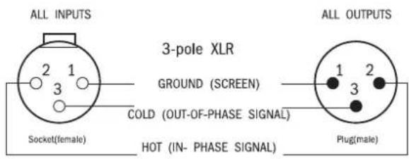
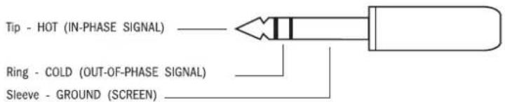
1/4" Stereo Jack Plug used as balanced Input/Output:
All Jacks Except Headphones
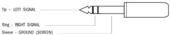
1/4" Stereo Jack Plug used For Headphones
Lamp Connectors

MIDI Connectors
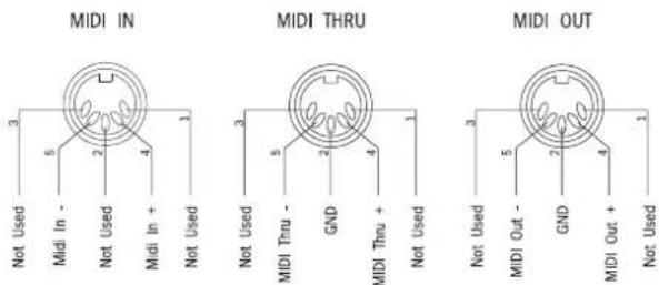
The MIDI IN signal is buffered by an opto-isolator.
Block Diagrams
Mono Input

![graph TD A["Input & Insert"] --> B["VCA SUM, MUTE & SOLO"] B --> C["SOLO"] C --> D["FADER"] D --> E["SOLO"] E --> F["PRE_R"] F --> G["PRE_L"] G --> H["AUX MUTE & BUFFERS"] H --> I["SNO_L"] I --> J["PRE_L"] J --> K["AUX_PST > 0dBu"] K --> L["RIGHT HAND PRE-AMP FILTER INSERT & EQ."] L --> M["AUX9_10_1…](/content/2026/06/1361911/images/b3363189a7d57e9b25219336927d4e16bc0d39a6a49d85a8f996e984f6a1418b.jpg)
![graph TD A["MASTER OUT"] --> B["FROM CPU"] B --> C["VCA BUSSES"] C --> D["VU 1-8"] D --> E["METER SOURCE SELECT"] E --> F["AUX1-8 AUX9-16/GRP1-8 MATRIX1-8"] F --> G["AUX AUX/GRP SOURCE SELECT"] G --> H["2TRK LEVEL"] H --> I["+10"] I --> J["MIX"] J --> K["SOLO BUS SWITCHING"] K --> L["FROM CPU"] L --…](/content/2026/06/1361911/images/a3fc85b18ca41ef0cecec39b0e4cd45200a165af8a4bb3cedec7fe7fd745cc02.jpg)
![graph TD A["AUX1:3.5:7"] --> B["AUX2:4.6:8"] C["AUX9:11:13,15 GRP1:3.5:7"] --> D["AUX10:12:14,16 GRP2:4.6:8"] E["LEFT"] --> F["CENTRE"] G["RIGHT"] --> H["SOLO PST"] I["SOLO PRE"] --> J["OP/AFL"] K["OP/AFL"] --> L["MATRIX 1:3.5:7"] L --> M["MATRIX 2:4.6:8"] N["TB/OSC"] --> O["TB"] P["AUX SUM"] --> Q[…](/content/2026/06/1361911/images/60074a4003671c51f380a5da7efba85a4230157242d3333c2091843fbf5ae8e8.jpg)
![graph TD A["AUX13.5.7 AUX24.6.8"] --> B["GRP/AUX SUM"] C["AUX91.13.15 GRP13.5.7 AUX1012.14.16 GRP24.6.8"] --> D["GRP/AUX AFL"] E["AUX17.18.19.20"] --> F["GRP/AUX SUM"] G["LEFT"] --> H["SOLO PST"] I["RIGHT"] --> J["SOLO PRE"] K["OP AFL"] --> L["MATRIX 13.5.7"] M["MATRIX 24.6.8"] --> N["TB/OSC"] O["AU…](/content/2026/06/1361911/images/5bb9a5249aff4ad020dcbf8cea1b87d1c0759bd4ef98697a82c3060253cd9760.jpg)
![graph TD A["AUX1 3.5.7"] --> B["LEFT CENTRE RIGHT"] C["AUX2 4.6.8"] --> D["SOLLO PRE OP AFL"] E["AUX9 11.13 15 GRP1 3.5.7"] --> F["MIX L MATRIX SENDS"] G["AUX10 12.14 16 GRP2 4.6.8"] --> H["MIX L SUM"] I["AUX17 18.19 20"] --> J["CHASS"] K["LEFT SOLO PRE OP AFL"] --> L["TRI"] M["SOLO PRE OP AFL"] -->…](/content/2026/06/1361911/images/bcd83286ef4ffc2d84f0666f3816a2c5f03a8e6f19a07d031e933ffafe2c4f76.jpg)

Console Operation

GAIN
GAIN adjusts the sensitivity of the electronically balanced XLR input. XLR input gain: +15dBu to +60dBu, with -20dB gain change switch.
The Split Output XLR carries a parallel passive split from the signal connected to the input XLR, for output to a FOH console if the MH4 is being used in Monitor mode. The pin 1 of this XLR can be disconnected from chassis using the Pin1 Lift switch adjacent to the XLR.
Phantom Power
The 48V switch (illuminated) applies 48V phantom power to the input XLR. The switch illumination is controlled by detecting the presence of phantom power on the XLR socket, and so the switch will also illuminate if phantom power is applied via the other end of a multicore. There is a 48V repeater LED on the rear panel, which is in parallel with the switch LED, and gives a useful indication of the presence of phantom power when patching at the rear of the console.
Note that the switch illumination and repeater LED will remain on for several seconds after phantom power is removed or switched off: this is due to the discharge time of the blocking capacitors on the input, it does not mean there is a fault.
-20dB
The - 20 switch reduces the input sensitivity by 20dB, to allow line or high-level mic signals to be connected via the XLR.
Peak LED
The Peak LED is intended to give a more convenient indication of overload conditions whilst adjusting the input gain control. It is driven by a three-point peak detector circuit, this monitors the signal post input amp, post-EQ and post-fader. The LED illuminates when the internal signal reaches +18dBu.
PHASE
PHASE reverses the polarity of the selected signal, immediately after the input stage.
HI-PASS
The HI-PASS rotary control controls the second order variable high-pass filter. The frequency is variable from 30-400Hz. The filter is switched in using the IN switch.
EQ
The EQ section is four band, with shelving sweep high and low frequency sections, and fully parametric high-mid and low-mid bands.
The HF section has cut or boost of 15dB (upper dual-concentric knob) and the frequency is variable between 1.2kHz and 20kHz (lower dual-concentric knob.)

The slope of the shelving response is steeper than previous designs; this creates a more focussed EQ which affects the high frequencies without boosting harsh upper mids.
The HIGH MID section has maximum cut or boost of 15dB (upper dual-concentric knob) and the frequency is variable between 750Hz and 12kHz (lower dual-concentric knob.)
The Q control varies the Q from 0.5 to 3.
The LOW MID section has maximum cut or boost of 15dB (upper dual-concentric knob) and the frequency is variable between 75Hz and 1.2kHz (lower dual-concentric knob). The Q control varies the Q from 0.5 to 3.
The LF section has cut or boost of 15dB (upper dual-concentric knob) and the frequency is variable between 35Hz and 550Hz (lower dual-concentric knob). The circuit has a shelving type response using a new design which gives a slight gain dip above the turnover frequency in boost mode and the reverse in cut mode.
The EQ section is switched in by the EQ switch.
Insert Point
The module insert point provides a balanced send and return, at a nominal level of 0dBu. The signal is accessible via separate 1/4" jacks on the rear connector panel. The insert point may be set pre-or post-EQ by an internal switch (SW50).
INS Switch
The INS switch switches the insert return into the signal path. The insert send is always active, even when INS is not on.
Mono Aux Sends
There are 8 mono Aux sends, these are intended as FX sends in FOH use, or mono mixes for monitoring. Each send has 5db of gain at maximum.
PRE switches
Each pair of mono Auxes can be switched Pre or Post fader by the adjacent PRE switch.
The default Pre-fade signal for all Auxes is Post-EQ but can be changed to Pre-EQ by changing solder links on the pcb. (both feeds follow the channel mute)
DIR switch
The DIR switch allows the Aux 8 send pot to control the level sent to the Direct Output from the channel, instead of the Aux 8 bus.
When DIR is pressed, the source of the Aux 8 pot is normally Pre-EQ, but it can be changed to Post-EQ by changing solder links on the pcb.
Direct Output
A Direct Output is available from the channel via a balanced XLR on the rear panel.

The default source is post-fader, but can be changed to Pre-EQ by changing solder links on the pcb. If the DIR switch is pressed (see above) this source is replaced by the Aux 8 pot.
Groups and Stereo Aux sends
The dual-purpose FOH/Monitor capability of the MH4 comes from the way in which the lower Aux sends and Group routing switches can function differently depending on the required application. This is determined for each pair of busses by the setting of the GRP global mode switch. (There are four of these switches, each located on one of the Stereo Group modules).
Global GRP mode NOT SELECTED ('Monitor' Mode)
If the GRP mode switches are not selected, the console is in 'Monitor' mode on those busses. In this mode the four dual concentric sends function as Stereo Aux sends, numbered A9-10, A11-12, A13-14, A15-16, ideal for use as In-Ear or stereo wedge sends. The top knob controls level, with gain of 5dB at max. The lower knob controls Pan, with 3dB centre drop.
In this mode, the adjacent routing switches 1-2, 3-4, 5-6 and 7-8 will not function. Even if they are pressed in they will not illuminate or route signal.
The adjacent PRE switches allow the source for each pair of stereo sends to be switched Pre or Post fader.
The default Pre-fade signal for all Auxes (including the mono sends) is post-EQ but can be changed to Pre-EQ by changing solder links on the pcb. (both feeds follow the channel mute)
Global GRP mode SELECTED ('FOH' Mode)
If the GRP mode switches are pressed on the Stereo Group modules, the console is in FOH mode. In this mode the busses which are used in Monitor mode for Stereo Auxes 9-16, now become Subgroup busses, with fixed routing via the 1-2, 3-4, 5-6, 7-8 switches. Note that, unlike a conventional FOH console, the panning to these Groups does not follow the main channel Pan pot, but each pair has its own Pan, using the bottom of the adjacent dual concentric pot. This arrangement is designed to give more flexibility in routing, as even though the Group busses are routed in pairs, it is possible to route to any individual bus without tying up the main mix bus pan pot (this would allow up to 8 separate mono subgroups).
Alternatively, up to 4 stereo subgroups could be created, each with its own pan settings from the inputs.
As a bonus in FOH mode, the top knobs of the dual concentric pots are not wasted -these become an additional 4 mono Aux sends, numbered A17, 18, 19 and 20. These can be used for additional FX sends, and can be switched pre or post fader by the PRE switches. The mains for these sends are rotary controls located on the four Stereo Group modules.
Note that these 4 outputs do not function when the console is in Monitor mode.

Routing To Mix Busses
The signal is sent to two stereo mix busses and the mono bus using the MIX and C switches (illuminated).
The PAN control, which gives 3dB centre drop, operates on the STE bus signal.
The Mono bus is always fed directly with the post-fader signal, unless LCR panning is engaged.
LCR Panning
The LCR switch changes the mode of the Pan pot from normal left -right panning with a 3dB centre drop, to 3-way LCR panning, requiring both the mono bus and stereo mix bus to be routed, and the pan pot panning from left to mono, mono to right. When the pot is physically centred, there is no output from the left and right Pan pot outputs.

Fader
The fader is a long-throw 100mm type, with an expanded scale around the unity gain position.
MUTE
The MUTE switch mutes the signal to all busses, including pre-fade Aux sends. The mute circuit can also be activated by the mute group system, a SIP mute signal, a VCA mute signal or internal snapshot control from the scene computer. When the module is muted by any of these remote sources, the MUTE switch illuminates and will flash in the case of a SIP or VCA mute. The MUTE switch can be toggled in the Preview state to edit a group and will not affect the audio. (see SAFE/PREV LED below).
SAFE/PREV
The SAFE/PREV LED is used to indicate the Mute safe status of the channel or Preview mute status, if the console is in Preview mode. The channel is toggled in or out of SAFE mode using the MUTE switch, after first engaging EDIT SAFES mode on the main cpu panel. Steady illumination of the LED indicates a mute safe condition. Preview status is indicated by flashing illumination, upon entering Preview mode from the main module, if the Mute is present in the previewed mute group or scene.
Meter
A 12-segment LED bar-graph meter next to the fader meters the signal at the input amplifier (this can be changed to post-fade using solder links on the input module pcb). The input gain should be adjusted so that the signal is using as much as possible of the headroom displayed by the meter. The actual clipping point of the channel is +21dBu.
VCA Assign LEDS
The module is assigned to the 8 VCA Groups using the SOLO button on each channel, in conjunction with the VCA Main SOLO switches. The whole console has to be switched into VCA Assign Mode (press the "VCA Assign Mode" switch located at the top of the main cpu panel) in order for the SOLO switch functions to be changed in this way. The current VCA assignments are indicated on the 8 VCA Assign LEDs adjacent to the fader.
SOLO
The electronically latching SOLO switch feeds a mono pre-fade signal to the monitor wedge and phones outputs, and the solo bus output.
If INPUT PRIORITY is selected on the main fader panel, this signal will replace any soloed Group, Aux or Matrix signals.
If AUTO CANCEL mode is active on the main fader panel, then any previously active input or output SOLOs will be cancelled, unless INPUT PRIORITY is also active, in which case only other input SOLOs will be cancelled.
The SOLO can be remotely cleared either by the SOLO CLEAR button on the main section, or by any other input or output SOLO if AUTO CANCEL is active (unless IP Priority active -then only other input SOLOs will clear it).
Solder Link Options
The MH4 contains some optional links which allow certain internal signal feeds to be changed to suit user preference. For maximum reliability these are solder links, rather than push-on jumpers, in most cases.
Each link has its function identified by text on the pcb.
To change the default setting it is necessary to remove a surface-mount resistor which sets the default routing, and then create a solder bridge between the relevant pair of solder pads. Once the resistor is removed it can be discarded. A second pair of solder pads adjacent to the resistor allows the default setting to be restored if required.
| Function Options Default | (set by) | |
| Insert Point * pre or post-EQ pre EQ (*) | ||
| Input meter source preamp out or post fader | preamp out (R225) | |
| Aux PRE source muted pre or post-EQ muted post EQ (R226) | ||
| Aux 8-Direct source Pre-EQ or post-EQ, (non-muted) | Pre-EQ (non-muted) (R227) | |
| Direct source (DIR switch UP) | Pre-EQ or Post-Fade Post-Fade (R228) | |
* controlled by switch SW50 on pcb, not solder link.
Input and Output Levels
| INPUT | |
| gain +15dBu to +60dBu (-5dBu to +40dBu with -20 switch) | |
| maximum input level +26dBu | |
| input impedance 2kohms | |
| INSERT SEND | |
| nominal level 0dBu | |
| maximum output level +21dBu into 2kohms | |
| output impedance <75ohms | |
| INSERT RETURN | |
| sensitivity 0dBu | |
| maximum input level | +21dBu |
| input impedance >10kohms | |
| DIR OUTPUT | |
| nominal level | 0dBu |
| maximum output level | +21dBu into 2kohms |
| output impedance <75ohms | |

Rear Connectors
INPUT (3 pin female XLR)
Pin 1 Ground
Pin 2 Signal Hot
Pin 3 Signal Cold
SPLIT O/P (3-pin male XLR)
Pin1 Ground
Pin2 Signal Hot
Pin3 Signal Cold
INSERT SEND (1/4" TSR Jack)
Tip Signal Hot
Ring Signal Cold
Sleeve Ground
INSERT RETURN (1/4" TSR Jack)
Tip Signal Hot
Ring Signal Cold
Sleeve Ground
DIR O/P (3-pin male XLR)
Pin1 Ground
Pin2 Signal Hot
Pin3 Signal Cold
The SPLIT 0/P is a passive parallel split from the input XLR, intended for feeding to the FOH multicore if the console is being used in the monitor position.
The GND LIFT switch disconnects pin 1 of the XLR from chassis ground. This affects the split output only.

Four stereo input modules are fitted as standard to all frame sizes, but more can be added in by replacing mono channels. The integral backpanel and common fader panel mean that individual stereo inputs can be fitted anywhere within the input section of the console.
GAIN
GAIN adjusts the sensitivity of left and right inputs together. Both inputs are available on XLRs and are electronically balanced.
XLR input gain: +15dBu to +60dBu, with -20dB gain change switch.
Phantom Power
The 48V switch (illuminated) applies 48V phantom power to the input XLR. The switch illumination is controlled by detecting the presence of phantom power on the XLR socket, and so the switch will also illuminate if phantom power is applied via the other end of a multicore. There is a 48V repeater LED on the rear panel, which is in parallel with the switch LED, and gives a useful indication of the presence of phantom power when patching at the rear of the console.
Note that the switch illumination and repeater LED will remain on for several seconds after phantom power is removed or switched off: this is due to the discharge time of the blocking capacitors on the input, it does not mean there is a fault.
-20dB
The -20 switch reduces the input sensitivity of both left and right channels by 20dB, to allow line level signals to be connected via the XLR.
Peak LED
The Peak LED is intended to give a more convenient indication of overload conditions whilst adjusting the input gain control. It is driven by a four-point peak detector circuit, this monitors the signal post input amp and post-EQ on both left and right channels. The LED illuminates when the internal signal reaches +18dBu. The Peak LED responds to whichever is the highest of the left or right signals.
PHASE
PHASE reverses the polarity of the left channel, immediately after the input stage.
MONO L
The MONO L switch cuts the right input signal, and feeds the left signal to both left and right module paths.
MONO R
The MONO R switch cuts the left input signal and feeds the right input to both left and right module paths.
If both the above switches are pressed at the same time, a sum of left and right inputs is fed to both paths of the module.

High-Pass Filter
The HI-PASS IN switch switches in a second order filter with turnover at 80Hz.
EQ
The EQ section is a stereo 4 band, with sweepable frequencies on all bands.
The HF section has cut or boost of 15dB (upper dual-concentric knob) and the frequency is variable between 1.2kHz and 20kHz (lower dual-concentric knob.) The section has a shelving response.
The HIGH MID section has maximum cut or boost of 15dB (upper dual-concentric knob) and the frequency is variable between 750Hz and 12kHz (lower dual-concentric knob.) The Q is fixed at 1.3.
The LOW MID section has maximum cut or boost of 15dB (upper dual-concentric knob) and the frequency is variable between 75Hz and 1.2kHz (lower dual-concentric knob). The Q is fixed at 1.3.
The LF section has cut or boost of 15dB (upper dual-concentric knob) and the frequency is variable between 35Hz and 550Hz (lower dual-concentric knob.) The section has a shelving response.
The EQ section is switched in by the EQ switch.
Insert Point
The left and right insert points provide a balanced send and return, at a nominal level of 0dBu. The signal is accessible via separate 1/4" jacks on the rear connector panel. The insert points are fixed as pre-EQ.
The insert return signals (both left and right) from the rear panel jack are enabled by pressing the INSERT IN switch. The insert send signals are always available at the rear panel, regardless of this switch setting.
Mono Aux Sends
There are 8 mono Aux sends, these are intended as FX sends in FOH use, or mono mixes for monitoring. Each send has 5dB of gain at maximum. Each send is fed from a mono sum of the module L and R signals.
PRE switches
Each pair of mono Auxes can be switched Pre or Post fader by the adjacent PRE switch. The Pre-fade signal is also a mono sum of the left and right channels.
The default Pre-fade signal for all Auxes is Post-EQ but can be changed to Pre-EQ by changing solder links on the pcb. (both feeds follow the channel mute).
Groups and Stereo Aux sends
The dual-purpose FOH/Monitor capability of the MH4 comes from the way in which the lower Aux sends and Group routing switches can function differently depending on the required application. This is determined for each pair of busses by the setting of the GRP global mode switch. (There are four of these switches, each located on one of the Stereo Group modules).

Global GRP mode NOT SELECTED ('Monitor' Mode)
If the GRP mode switches are not selected, the console is in 'Monitor' mode on those busses. In this mode the bottom four sends function as Stereo Aux sends, numbered A9-10, A11-12, A13-14, A15-16, ideal for use as In-Ear or stereo wedge sends. The module left side is sent to the odd-numbered busses, and the right to even, with gain of 5dB at max. The L-R balance to the bus pairs is controlled by the main channel balance control.
In this mode, the adjacent routing switches 1-2, 3-4, 5-6 and 7-8 will not function. Even if they are pressed in they will not illuminate or route signal.
The adjacent PRE switches allow the source for each pair of stereo sends to be switched Pre or Post fader.
The default Pre-fade signal for all Auxes (including the mono sends) is post-EQ but can be changed to Pre-EQ by changing solder links on the pcb. (both feeds follow the channel mute)
Global GRP mode SELECTED ('FOH' Mode)
If the GRP mode switches are pressed on the Stereo Group modules, the console is in FOH mode. In this mode the busses which are used in Monitor mode for Stereo Auxes 9-16, now become Subgroup busses, with fixed routing via the 1-2, 3-4, 5-6, 7-8 switches. The left module signal is fed to the odd-numbered busses, and the right to even. The L-R balance to the bus pairs is controlled by the main channel balance control.
As a bonus in FOH mode, the send pots used for stereo Auxes in Monitor mode are not wasted -these now become an additional 4 mono Aux sends, numbered A17, 18, 19 and 20. These are fed with a mono sum of the module signal, and can be switched pre or post fader by the associated PRE switches. The mains for these sends are rotary controls located on the four Stereo Group modules.
Note that these 4 outputs do not function when the console is in Monitor mode.
Routing To Mix Busses
The signal is sent to the stereo mix bus and the mono bus using the MIX and C switches (illuminated).
Balance
The BAL control allows the left signal to be faded down to zero level when turned fully clockwise, and vice versa for the right signal. In the centre position, both channels are fed at unity gain to the Mix bus. The balance control also affects the signal balance to the stereo Aux sends or group busses, as described above.
The C bus is always fed directly with a mono sum of the stereo post-fader signal.
The relative contribution of left and right signals to the mono sum, used for mono auxes and centre bus feed, is also controlled by the balance control.

Fader
Post-fader signal level is controlled via the left and right VCAs by a 100mm VCA fader.
SOLO
The electronically latching SOLO switch feeds a stereo pre-fade signal to the monitor and phones output, and the solo bus outputs.
If INPUT PRIORITY is selected on the main module, this signal will replace any soloed group signals.
If AUTO CANCEL mode is active on the main, then any previously active input or output SOLOs will be cancelled, unless INPUT PRIORITY is also active, in which case only other input SOLOs will be cancelled.
The SOLO can be remotely cleared either by the SOLO CLEAR button on the main section, or by any other input or output SOLO if AUTO CANCEL is active (unless IP Priority active -then only other input SOLOs will clear it).
MUTE
The MUTE switch mutes the signal to all busses, including pre-fade Aux sends. The mute circuit can also be activated by the mute group system, a SIP mute signal, a VCA mute signal or internal snapshot control from the scene computer. When the module is muted by any of these remote sources, the MUTE switch illuminates and will flash in the case of a SIP or VCA mute. The MUTE switch can be toggled in the Preview state to edit a group and will not affect the audio. (see SAFE/PREV LED below).
SAFE/PREV
The SAFE/PREV LED is used to indicate the Mute safe status of the channel or Preview mute status, if the console is in Preview mode. The channel is toggled in or out of safe mode using the MUTE switch, after first engaging EDIT SAFES mode on the main cpu panel. Steady illumination of the LED indicates a mute safe condition. Preview status is indicated by flashing illumination, upon entering Preview mode from the main module, if the Mute is present in the previewed mute group or scene.
VCA Assign LEDs
The module is assigned to the 8 VCA Groups using the SOLO button on each channel, in conjunction with the VCA Main SOLO switches, when the console is in VCA Assign mode. This mode is engaged by pressing the "VCA Assign Mode" switch on the main cpu panel. The current VCA assignments are indicated on the 8 VCA Assign LEDs adjacent to the fader. The left and right VCAs in the module are automatically assigned as a pair to the required VCA group.
Meter
A 12-segment LED bar-graph meter next to the fader meters the stereo signal and displays the highest of left or right, at the input amplifier (this can be changed to be post-fade using solder links on the input module pcb).
Note:
The stereo fader electronics is identical to that of the mono; only the knob colour is different. Therefore, stereo modules can be moved or fitted anywhere in the console without changing the fader section. Conversely, mono inputs could also be fitted in place of the four standard stereo modules to the left of the main section.
Solderlink Options
The MH4 contains some optional links which allow certain internal signal feeds to be changed to suit user preference. For maximum reliability these are solder links, rather than push-on jumpers, in most cases.
Each link has its function identified by text on the pcb.
To change the default setting it is necessary to remove a surface-mount resistor which sets the default routing, and then create a solder bridge between the relevant pair of solder pads. Once the resistor is removed it can be discarded. A second pair of solder pads adjacent to the resistor allows the default setting to be restored if required.
| Function Options Default (set by) | ||
| Input meter source preamp out or post fader | preamp out (R242 & R247) | |
| Aux PRE source L muted | pre or post-EQ muted post-EQ (R178) | |
| Aux PRE source R muted | pre or post-EQ muted post-EQ (R185) | |
Input and Output Levels
| L, R INPUTS | |
| gain +15dBu to +60dBu, (-5 to +40dBu with -20 switch pressed) | |
| maximum input level +26dBu | |
| input impedance 2kohms | |
| INSERT SENDS | |
| nominal level 0dBu | |
| maximum output level +21dBu into 2kohms | |
| output impedance <75ohms | |
| INSERT RETURNS(electronically balanced) | |
| sensitivity 0dBu | |
| maximum i/p level +21dBu | |
| input impedance >10kohms balanced | |

Rear Connectors
LEFT, RIGHT INPUTS (3-pin female XLR)
Pin 1 Ground
Pin 2 Signal Hot
Pin 3 Signal Cold
LEFT, RIGHT INSERT SEND (1/4" TSR Jack)
Tip Signal Hot
Ring signal Cold
Sleeve Ground
LEFT, RIGHT INSERT RETURN (1/4" TSR Jack)
Tip Signal Hot
Ring Signal Cold
Sleeve Ground
Output Section - Overview
Dual Aux

Stereo Group

The Output Section is made up of eight 2-wy Output modules, giving control of the 16 output busses plus the additional 4 Aux busses which are only available in GRP mode. The fader panel below these output modules contains the 8 VCA main faders. The first four 2-way modules (Dual Aux) control the 8 mono Aux outputs, plus the 8 Matrix main controls.
The second four 2-way modules (Stereo Group) control the 8 dual-function Grp/Aux outputs, and have stereo 4-band EQ, for in-ear Monitor applications, instead of the Matrix outputs.
The upper section of both types of module contain sends to the 8 Matrix outputs.

The first half of the output section is made up of four 2-wy Aux-only output modules, handling the outputs from the full-time Aux sends 1-8 on the input modules.
Aux Insert Point (on rear panel)
The Aux Insert point provides send and return on separate 1/4" jack sockets on the rear panel. The nominal level is OdBu.
The insert point is pre the Aux output fader.
External Input
The Aux External input from 1/4" jacks on the rearcon are electronically balanced inputs at OdBu, which are then summed directly onto the Aux busses, to allow linking of a secondaryconsole or other source. The level can be varied from off to +10dB, using the EXT IN rotary control. The input is enabled with the ON switch. The arrow switch allows the external input to be used by the matrix section, see later.
Fader
The 60mm output fader controls the level of the signal from the Aux bus fed to the Aux output, with 10dB of gain at maximum.
The Aux output itself is electronically balanced at OdBu, on a male XLR on the rearcon.
MUTE
The main output MUTE switch mutes the signal to the Aux output and MIX and C busses (if routed). The Mute switch is controlled by the mute group and snapshot automation systems, but not the solo-in-place system. The MUTE switch can be toggled if Preview mode is enabled on the console, to edit a mute group or scene, and will not affect the audio.
SAFE/PREV LED
The SAFE/PREV LED is used to indicate the Mute safe status of the console or Preview mute status, if the console is in preview mode. The group/aux is toggled in or out of safe mode using the MUTE switch, after first engaging EDIT SAFES mode on the main cpu panel. Preview status is indicated by flashing illumination, upon entering Preview mode from the main cpu panel, if the Mute is present in the previewed mute group or scene.

AFL
The AFL switch feeds the post fade output signal to the stereo AFL busses. The AFL signal is actually derived from the Output Pan control -this allows a stereo AFL signal to be generated which is likely to be appropriate to the application. EG: If using as stereo auxes, the pan pots can be turned hard left and right on adjacent outputs and this will generate a stereo AFL, if both adjacent AFL buttons are pressed. Adjacent AFL switches can be linked so that pressing one will automatically select both; to do this, press and hold the first AFL switch, then press the second. To un-link the switches, repeat the process. If using separate mono auxes, the pan pots can be centred to give mono image from each AFL button.
If a pair of adjacent AFL switches have been linked, they act as one switch as far as Autocancel is concerned.
If INPUT PRIORITY is enabled on the main fader panel then any active input SOLOs will replace the output AFL signal, and the output will not be heard until the inputs are un-SOLOed.
Pressing an AFL switch will also send a MIDI message to an attached BSS varicurve or dbx DriveRack system, instructing them to select the appropriate channel of EQ for control on the BSS/dbx remote unit.
Routing To The Mix
The Aux to mix MIX and C switches route the post-fade, post mute output signal to the stereo Mix L, R and C busses respectively.
The feed to the stereo mix bus is taken via the PAN control which has a 3dB centre drop.
The PAN control also affects the AFL image, as described above.
TB/OSC
The latching TB/OSC switch feeds the signal from the talkback mic or oscillator (located on the main module) to the Aux output and is injected onto the bus with no dimming of the Aux signal. The TALK or OSCILLATOR INT buttons on the main module must also be switched on to enable this operation.
Meters
The Group/Aux output level is metered by one of 8 VU meters in the overbridge. Three bank select switches on the main module determine whether the 8 Stereo Aux/Groups, 8 Auxes or the 8 Matrix outputs are fed to the meters.
Matrix Sends
The matrix send pots feed the odd-numbered Aux output signal (left-hand column of knobs) or the even-numbered Aux output (right-hand column of knobs) to the Matrix output M1-8.
The PRE switch sources this feed pre the AUX main fader. The pre-fade feed is post-insert.

Matrix Section
Each 2-wy Aux-only Output module contains two of the eight Matrix Output sections, together with sends from each of the two Aux outputs on the module, into the 8 matrix outputs. The 8 Group/Aux output sections also have sends into the 8 matrix outputs. Together with an external input to each matrix, (shared with the Aux bus input) and the matrix sends on the main module from Mix and C, this gives a matrix configuration of 20x8.
The feed from each Grp/Aux or Aux section to the matrix send section can be sourced pre or post the Grp/Aux fader, using the PRE switch (The pre-fade feed is post-insert).
Sends
The 8 Matrix Send pots feed the pre-or post fade Aux Output to the 8 matrix mix busses.
In the Matrix Main section, the appropriate buss is fed to a summing amp and then to the Matrix insert send.
Matrix Main Fader
The Matrix Main rotary fader controls the level sent to the electronically balanced output stage. It has 10dB of gain at maximum.
The balanced signal is fed to the matrix output connector (male XLR) on the rear con.
Matrix Insert Point
The Matrix Insert point is pre-fade and uses a balanced send and return, at a nominal level of OdBu. The insert SEND and RETURN are accessible via separate 1/4" jacks on the rear connector panel.
Mute
The MUTE switch mutes the Matrix output signal. The mute is controlled by the mute group and snapshot system, but not by the solo-in-place system. The MUTE switch can be toggled in the Preview state to edit a group and will not affect the audio.
SAFE/PREV LED
The SAFE/PREV LED is used to indicate the Mute safe status of the console or Preview mute status, if the console is in preview mode. The group/aux is toggled in or out of safe mode using the MUTE switch, after first engaging EDIT SAFES mode on the main cpu panel. Preview status is indicated by flashing illumination, upon entering Preview mode from the main cpu panel, if the Mute is present in the previewed mute group or scene.

The External Input
Each Matrix section can steal the external input from the Aux bus external input socket by pressing the EXT to MTX (arrow) switch below each matrix main section. This allows the external input to be mixed in, via its existing level control and ON switch, to the matrix output. When this switch is pressed, it is obviously not possible to use the external input to the Aux bus.

The second half of the output section consists of four dual-function Group/Aux modules, which handle the outputs from either 4 stereo Aux sends, or 8 Groups, plus the 4 additional mono Aux sends 17-20.
Group/Aux Insert Point (on rear panel)
The Group/Aux Insert point provides send and return on separate 1/4" jack sockets on the rear panel. The nominal level is OdBu.
The insert point is pre the Grp/Aux output fader.
External Input
The Grp/Aux External inputs from 1/4" jacks on the rearcon are electronically balanced inputs at 0dBu, which are then summed directly onto the Grp/Aux busses, to allow linking of a secondaryconsole or other source. These inputs are treated as a stereo pair and the level can be varied from off to +10dB, using the stereo EXT IN rotary control. The pair of inputs is enabled with the ON switch.
MIX Switch
The External input can be routed to the Mix L&R buses, instead of the local Group/Aux busses, by pressing the MIX switch.
EQ
The stereo Equaliser is either in line with the output signal or can be flipped into the external input path using the FLIP (arrow) switch. The circuit and control functions are identical to the EQ on the stereo input module. The stereo EQ is switched in by the EQ switch.
Fader
The 60mm output fader controls the level of the signal from the Group/Aux bus fed to the Group/Aux output, with 10dB of gain at maximum.
The Group/Aux output itself is electronically balanced at OdBu, on a male XLR on the rearcon.
MUTE
The main output MUTE switch mutes the signal to the Group/Aux output and MIX and C busses (if routed). The Mute switch is controlled by the mute group and snapshot automation systems, but not the solo-in-place system. The MUTE switch can be toggled in the Preview state to edit a mute group or scene, and will not affect the audio.
SAFE/PREV LED
The SAFE/PREV LED is used to indicate Mute safe mode or Preview mode. The group/aux is toggled in or out of safe mode using the MUTE switch, after first engaging EDIT SAFES mode on the main cpu panel. Preview status is indicated by flashing illumination, upon entering Preview mode from the main cpu panel, if the Mute is present in the previewed mute group or scene.

AFL
The AFL switch feeds the post fade output signal to the stereo AFL busses. The AFL signal is actually derived from the Output Pan control -this allows a stereo AFL signal to be generated which is likely to be appropriate to the application. EG: If using as stereo groups or Auxes, the pan pots can be turned hard left and right on adjacent outputs and this will generate a stereo AFL, if both adjacent AFL buttons are pressed. Adjacent AFL switches can be linked so that pressing one will automatically select both; to do this, press and hold the first AFL switch, then press the second. To un-link the switches, repeat the process.
If using separate mono groups, the pan pots can be centred to give mono image from each AFL button.
If a pair of adjacent AFL switches have been linked, they act as one switch as far as Autocancel is concerned.
If INPUT PRIORITY is enabled on the main fader panel then any active input SOLOs will replace the output AFL signal, and the output will not be heard until the inputs are un-SOLOed.
Pressing an AFL switch will also send a MIDI message to an attached BSS varicurve or dbx DriveRack system, instructing them to select the appropriate channel of EQ for control on the BSS/dbx remote unit.
Routing To The Mix
The Group/Aux to mix MIX and C switches route the post-fade, post mute output signal to the stereo Mix and C busses respectively.
The feed to the stereo mix bus is taken via the PAN control which has a 3dB centre drop when in normal L-R mode. This PAN control also affects the AFL image, as described above.
TB/OSC
The latching TB/OSC switch feeds the signal from the talkback mic or oscillator (located on the main module) to the Group/Aux output and is injected directly onto the bus with no dimming of the Group/Aux signal. The TALK or OSCILLATOR INTINNitions on the main module must be switched on to enable this operation.
Meters
The Group/Aux output level is metered by one of 8 VU meters in the overbridge -three bank select switches on the main module determines whether the 8 Stereo Aux/Groups, 8 Auxes or the 8 Matrix outputs are fed to the meters.
Aux Main Aux 9-12 Outputs
Each of the four 'extra' aux send outputs are only available when the corresponding output module is set to global GRP mode, and receives signal from the top knobs of the input dual concentric send pots via 4 additional dedicated busses. An output rotary fader is provided, with 10dB gain, plus an AFL button. The balanced output is available on the rear panel.

Global Switching
The Global Grp/Aux mode switch sends a logic voltage to the input modules to reconfigure the busses and routing switches for either FOH or Monitor applications. This switch has no effect on any functions within the output module itself; all facilities are available in either mode, e.g. the stereo EQ is always available, whether the output is configured as a Stereo Aux or a Group.
There is one global mode switch on each of the four Stereo Group Output modules, i.e. one for each pair of outputs.
Matrix Sends
The matrix send pots feed the odd-numbered Grp/Aux output signal (left-hand column of knobs) or the even-numbered Grp/Aux output (right-hand column of knobs) to the Matrix output M1-8.
The PRE switch sources this feed pre the GRP/AUX main fader. The pre-fade feed is post-insert.
Input and Output Levels
| INSERT SENDS | |
| nominal level 0dBu | |
| maximum output level +21dBu into 2kohms | |
| output impedance <75ohms | |
| GROUP/AUX/MTX OUTPUTS | |
| nominal level 0dBu | |
| maximum output level +21dBu into 2kohms | |
| output impedance <75ohms | |
| INSERT RETURNS, EXTERNAL INPUTS | |
| sensitivity 0dBu | |
| maximum i/p level +21dBu | |
| input impedance >10k balanced | |
Rear Connectors
INSERT RETURN, GRP/AUX/MTX EXTERNAL INPUTS (1/4" TSR Jack)
Tip Signal Hot
Ring Signal Cold
Sleeve Ground
INSERT SEND (1/4" TSR Jack)
Tip Signal Hot
Ring Signal Cold
Sleeve Ground
GROUP/AUX/MTX OUTPUTS (3 pin male XLR)
Pin 1 Ground
Pin 2 Signal Hot
Pin 3 Signal Cold


The fader panel below the Stereo Group and Dual Aux output modules contains the main faders and Mute and SOLO switches for the 8 VCA groups. The SOLO switches are also used for programming VCA assignments, when the console is in VCA Assign mode.
VCA Main Fader
The 100mm VCA main fader controls the levels of any channel VCAs assigned to that group. The control is performed by hardwired control busses, although the assignments are done by software control.
VCA MUTE
The VCA MUTE switch triggers a Mute condition on any input channels assigned to that VCA group. The Mute switch LED on the inputs will flash, to differentiate VCA mute from Mute Group or Scene mutes. The VCA mute is not stored with mute scenes or mute groups.
VCA SOLO & Assigning VCAs
The VCA SOLO switch acts as a remote control for the SOLO switches on any input channels that are assigned to the VCA. However, whereas the normal solo mode for inputs is PFL, soloing from a VCA main will automatically change this to a stereo AFL solo. If SIP is activated via the main, the soloing the VCA main generates a normal SIP solo from the inputs assigned to that group (i.e.: all other inputs are muted).
The VCA SOLO switch is also used to assign inputs to VCA groups. The VCA ASSIGN mode switch is first pressed on the main fader panel. The VCA SOLO switch is then pressed on the one or more VCA mains to which it is necessary to assign inputs. When the SOLO switches on input modules are now pressed, those inputs will be assigned to the chosen VCA main(s), and their VCA Assign LEDs will display this assignment. Note: if the input was already assigned to the chosen VCA, doing this will de-assign it.
To clear all assignments on a particular input channel, all VCA main SOLO buttons are turned off, and when the input SOLO buttons are pressed, the assignments are cleared.
To clear an individual assignment, repeat the process for assigning the VCA: the input SOLO switches act as toggles, and can de-assign as well as assign.

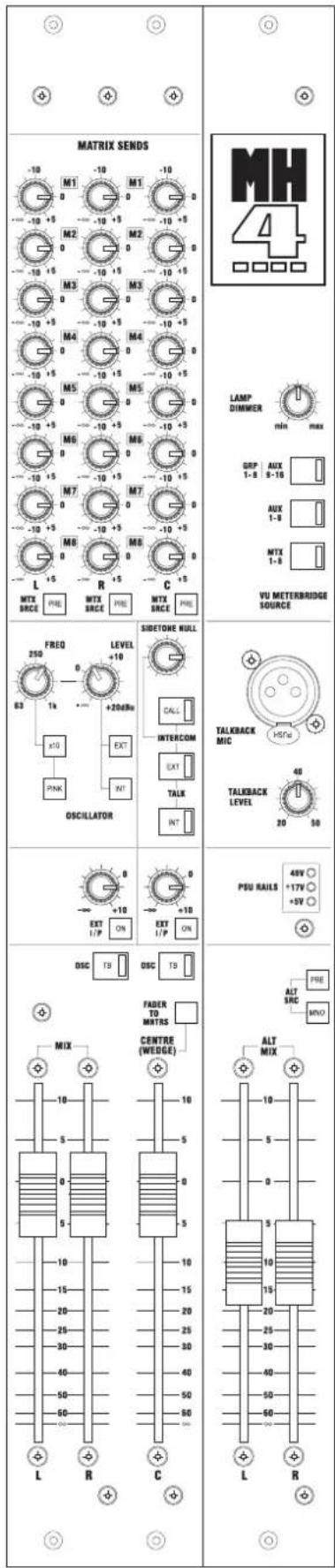
The main facilities are split between two modules situated immediately to the right of the last Stereo Group Output module. This section contains the stereo mix output, alternate stereo mix output, mono (C) mix output, a noise or sine wave test oscillator, and internal/external talkback functions. The associated section of the fader panel below the main section contains the monitor and headphone outputs, 2-Track return and monitor source controls, plus the controls for the Solo System.
Main Outputs
Faders
The Stereo Mix Left and Right and Centre Mix signals are controlled by the MIX L and R and C Faders. There is 10dB of gain at the top of the faders. The left, right and centre outputs are balanced and appear on male XLR connectors on the rear panel.
Fader To Monitors
The Fader to Mntrs switch allows the Centre fader to take control of the Monitor Outputs, normally controlled by the Monitor level rotary control on the main fader panel. Pressing this switch effectively turns the Centre Fader into a stereo wedge fader, for use in a stage monitor application.
Insert Points
The Mix L and R and Centre insert points are pre-fade using a balanced send and return, at a nominal level of 0dBu. The send and returns appear on separate 1/4" jacks on the rear panel.
TB/OSC
The TB/OSC switch arms the Mix L and R and/or Centre outputs to receive talkback or oscillator from the main section. The TALK or OSCILLATOR INT switches must also be pressed.
ALT MIX Output
The ALT MIX output is an additional stereo output derived from the Mix outputs, and controlled by the ALT MIX L and R faders. The outputs appear on balanced male XLRs on the rear panel.
PRE
The PRE switch sources the ALT signal from pre the MIX main faders.
MNO
The MNO switch sends a mono sum of the MIX L and R signals to the ALT L and R outputs. This effectively gives two separately controllable mono outputs.

External Inputs
The Mix and Centre External inputs from 1/4" jacks on the rearcon are balanced inputs at OdBu, which are then summed directly onto the corresponding busses, to allow linking of a secondaryconsole or other source. The level can be varied from off to +10dB, using the EXT IN rotary controls. The inputs are switched in with their respective ON switch.
Matrix Sends
The Matrix Send pots feed the Mix left, Mix right and Centre Outputs to the 8 matrix mix busses, with 8 pots in each case.
PRE
The PRE switches determine whether the feed to all the matrix sends is pre or post the output fader, for each of the main outputs. The pre-fade feed is post insert-point.
Talkback
The talkback system allows communication by the operator to the all group, aux (not aux 17-20), matrix, stereo and mono outputs, and to and from an external console, using either the Soundcraft proprietary system or Clearcom-compatible 3-wire intercom interface.
The talkback switches (CALL, EXT, INT) are above the C Fader.
The TALKBACK pot controls the level of the talkback input, from the 3-pin TALKBACK MIC XLR on the main module front panel. The sensitivity of the input is variable between -20dBu and -50dBu.
48V phantom power can be applied to the mic socket if required, using an internal jumper (default setting =48V OFF). The jumper is located on the pcb: just behind the talkback mic XLR.
INT
The INT switch switches the talkback signal from the mic amp onto the internal TB/OSC bus, which is fed to all the output modules and the main output section of the main module.
The signal then passes through the individual latching TB/OSC switches on the output sections, which serve to arm the desired outputs to receive talkback (or oscillator, see next page).
EXT
The EXT switch initiates talkback to the remote console using the Soundcraft proprietary system.
The talkback mic signal is switched to the electronically balanced TALKBACK OUT XLR, with a +15v DC common-mode voltage to signal the remote console that talkback is occurring. An internal jumper disables the common-mode DC voltage, to allow use with non-Soundcraft desks. The action of pressing EXT also switches the TB mic signal onto the Clearcom signal line (connected to CLEARCOM IN or THRU), and any talkback signal being received on the Clearcom line is switched to the 'phones, dimming the program by 15dB. The amount of sidetone from the TB mic to the phones is set by the SIDETONE NULL control on the front panel.
If a 15V common-mode voltage is detected on the TB IN XLR, indicating Soundcraft talkback from the remote console, then the TB IN signal is switched to the 'phones output, dimming the existing signal by 15dB. The EXT switch LED also illuminates. In this case the switching is automatic, it is not necessary to press the EXT switch.
CALL
The CALL switch is only used for Clearcom talkback, and is a non-latching switch used to switch 10Vdc onto the intercom line. This is used to attract the attention of the remote station and get them to switch on their own 'Talk' switch. (The 'Talk' switch function on the console is provided by the EXT switch).
Additionally, an incoming 10V call signal will cause the console gooseneck lamps to flash. Note: pressing the console CALL switch will also cause the lamps to flash, this is normal.
Oscillator
The oscillator produces a sine wave with frequency variable between 63Hz and 1kHz by the FREQ pot.
The X10X10ton increases the frequency limits up to 630Hz and 10kHz.
The PINKRON switches the signal from sine wave to pink noise.
The oscillator signal is enabled to the TB/OSC bus and local enable switches by the OSC/INTOSC/INT and to its own rear panel output with the OSC/EXTOSC/EXT. The oscillator output is balanced at a nominal level of 0dBu, on a male XLR connector on the rear connector panel.
The LEVEL pot adjusts the level from off to +20dBu.
PSU Status Indicators
The three PSU Status Indicator LEDs (red) show that the PSU rails +48v, and +/-17v (both sets of rails) and 5V logic rail are working.
Lamp Dimmer
The LAMP DIMMER control adjusts the brightness of the gooseneck lamps connected to the rear of the console. The lamp sockets are designed for 12V 5W gooseneck lamps.
The flashing of lamps in response to a Clearcom call signal will operate regardless of the setting of the dimmer.
Monitor and Headphones Outputs
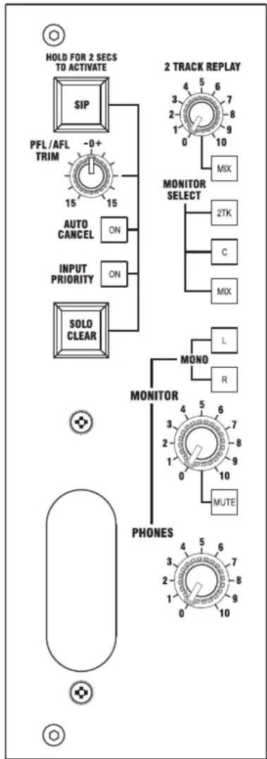
The Monitor Outputs and Headphones output share a common signal source and are controlled by the Monitor and Phones level controls respectively.
If the Fader to Mntr switch adjacent to the Centre O/P fader is pressed, the Centre O/P fader will take control of the Monitor level, becoming in effect a 'Wedge' fader for monitor applications. The Monitor pot will be disabled in this mode, and the Centre Output signal will be set to unity gain.
The Monitor Outputs are via Left and Right balanced XLRs on the rear panel.
MUTE
The MUTE switch mutes both left and right monitor outputs, but does not affect the phones.
MNO L & R
The MNO L and R switches allow either left only or right only monitor signals to be fed to both outputs. If both switches are pressed simultaneously, this sums both left and right channels together and feeds them to both outputs. These switches also affect the phones signal.
Phones Socket
The phones output socket is a stereo 1/4" jack, mounted in a recessed socket in the fascia.
Signal sources
The signal source for these outputs is selected using three monitor select switches.
- The MIXMIXSwitch routes the post-fade stereo mix signal to the monitor/phones outputs.
- The C C switch routes the post-fade Centre mix signal to both left and right monitor outputs.
- The 2TK2 switch routes a stereo line input from the balanced 1/4" jack 2Track Replay rear panel inputs, to the monitor/phones outputs. These three signals can be summed by simultaneous selection if required. (If MIX and C are both pressed for example, this would allow headphone monitoring of an LCR-panned input or group signal with approximately constant volume).
- Any PFL/AFL operation will override all of the above signals.
- If none of MIX, C or 2TK are selected, the monitors will still be able to receive PFL/AFL signals, but will otherwise be silent.
- The output of the automatic PFL/AFL switching is also used to feed the Left and Right VU meters in the overbridge. Note that the MIX switch must be pressed in order to meter the Mix signal on these VUs.
2 Track Replay
Input
The 2TRACK REPLAY rotary control adjusts the sensitivity of the stereo line input from the balanced 1/4" jack 2TK Replay rear panel inputs.
The MIXMwitch routes the 2TK Replay signal to the stereo mix.

Output
The REC Output is a stereo pair of RCA/phono outputs which are fed by a copy of the main MIX signal, level-reduced to -10dBV, for feeding to a cassette or minidisc recorder or similar.
The +CENTRE-sENTREadds the Centre Output signal to the left and right record outputs, to allow the recording to pick up the centre feed.


Introduction
The solo system works in one of three modes:
•mono/stereo PFL
• stereo AFL
- SIP (Solo-in-Place).
The selected mode applies to the whole console.
PFL & AFL
PFL and AFL are non-destructive modes, where the soloed signal is switched onto a stereo solo bus, and the monitor/phones and main meters are automatically switched over to receive the signal from this bus when a logic signal is detected from the soloed module. (The normal monitor source -Mix/C/2TK - is overridden).
Inputs normally solo as mono PFL, (with stereo inputs giving a stereo PFL) and Outputs as stereo AFL, but inputs can alternatively be soloed as stereo AFL, if they are members of a VCA group, by using the VCA main solo buttons.
Solo In Place
Solo-in-Place is a destructive mode, where the soloed channel sends a data signal to the CPU which then mutes all other channels, thus leaving only the soloed channel in whichever of the main outputs it has been routed to. There is no switching over of the monitor/phones outputs -they continue to monitor the stereo mix bus (unless an output is soloed -see next paragraph). Soloing another channel or switching it into mute safe mode, will unmute that channel.
SIP is only applicable from inputs -so any Group, Aux or Matrix output which is soloed while the console is in SIP mode will appear as an AFL as usual, switching over the monitor/phones output accordingly.
SIP
Solo-in-Place mode is selected by pressing the protected SIP switch on the CPU fader panel. This has to be held in for 2 seconds in order to activate it, but can then be cancelled by a single press.
PFL/AFL TRIM
The PFL/AFL trim control gives +/-15dB of gain adjustment to the PFL or AFL signals fed to the Monitor/phones outputs. The trim does not affect the solo level displayed on the main VU meters.
Solo Clear
The SOLO CLEAR button lights when any solo or AFL switch on the console is active; pressing it will cancel any solo/AFL switch active on the console regardless of the current solo mode.
Auto Cancel
When AUTO CANCEL is activated by its ON button, any solo/AFL switch will cancel any currently active solo, so only one channel can be active at once (except if Input Priority is enabled, see below).
Input Priority
If INPUT PRIORITY is activated by the ON button, an input solo will not clear an output AFL (even if autocancel is selected) but will cause the output solo audio signal to be replaced by the input solo audio for the duration of the input solo. When the input solo is deselected, the output solo will be heard again.
If Input Priority and Auto Cancel are selected at the same time, inputs will cancel other inputs, outputs will cancel other outputs, and the audio from input solos will temporarily replace that from the current output solo.
VCA Solo
When the solo button is pressed on a VCA main fader, the effect is as if the solo buttons on all inputs assigned to that VCA subgroup had been pressed, but instead of generating a PFL signal, the inputs generate an AFL signal. This is the only way in which AFL is possible from inputs.
If SIP mode is engaged, the VCA solo will trigger a solo-in-place solo as if all member channels' SIP switches had been pressed.
Console Linking
SOLO L,R Bus Inputs are provided for linking in a secondaryconsole: either another MH4 or any other console with solo bus outputs. These signals are from balanced 1/4" jacks on the rear panel, and are added directly to the busses, at unity gain.
SOLO L,R Bus Outputs are also provided, for use when linking consoles: these are balanced on male XLRs and are fed from the output of the summing amps.
See page 5 - 12 for full details of console linking.

Output/Input Levels
| MIX, ALT L/R, CENTRE, OSC, EXT TB, MNTR L/R, SOLO L,R OUTPUTS | |
| Nominal level: 0dBu | |
| Maximum output level: +21dBu into 2k ohms | |
| Output Impedance: <75 ohms | |
| EXT TB OUTPUT (Electronically Balanced, with 15V common mode dc voltage) | |
| Nominal level: 0dBu | |
| Maximum output level: +21dBu into 2k ohms | |
| Output Impedance: <75 ohms | |
| EXT TB, 2TK L,R INPUTS, BUS INPUTS: MIX L,R, CENTRE, SOLO L,R | |
| Nominal level: 0dBu | |
| Maximum Input level +21dBu | |
| Input impedance >10k ohms | |
| MIX L/R, CENTRE INSERT SENDS | |
| Nominal level: 0dBu | |
| Maximum output level: +21dBu into 2k ohms | |
| Output Impedance: <75 ohms | |
| MIX L/R, CENTRE INSERT RETURNS | |
| Nominal level: 0dBu | |
| Maximum Input level +21dBu | |
| Input impedance >10Kohms | |
| PHONES OUTPUT | |
| Output Impedance 50 ohms | |
| Max Output +20dBu into 400 ohms, +14dBu into 50 ohms | |
Rear Connectors
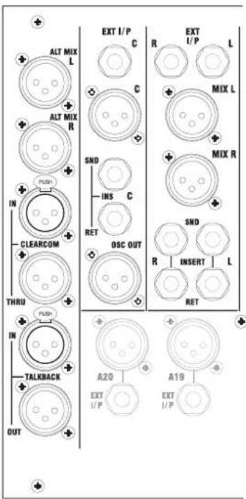
MIX, ALT L/R, Centre, Osc, Ext TB, Mntr L/R outputs, SOLO L,R Outputs (3 pin male XLR)
Pin 1 Ground
Pin 2 Signal Hot
Pin 3 Signal Cold
CLEARCOM IN (3 pin female XLR) & CLEARCOM THRU( 3 pin male XLR)
Pin 1 Intercom Ground
Pin 2 Intercom Power (Not used)
Pin 3 Intercom Signal
MIX L/R and Centre Insert Sends, Insert Returns, SOLO L,R Inputs, 2TK
L,R Inputs, MIX L,R and Centre Bus Inputs (1/4" TSR jack)
Tip Signal Hot
Ring Signal Cold
Sleeve Ground
EXT TB Input, TB Mic Input (3 pin female XLR)
Tip Signal Hot
Ring Signal Cold
Sleeve Ground
Phones Output (1/4" TSR jack)
Tip Left
Ring Right
Sleeve Ground

The Meterbridge is not designed to be removable from the console.
Meters
Three large VU meters with integral Peak LEDs meter the Mix left, right and Centre output signals. The left and right meters are sourced from the monitor section of the main modules, and they will automatically switch over to read PFL/AFL signals.
Note that the MIX switch on the monitor fader panel must be pressed in order to monitor the main mix on these meters.
The third meter permanently reads the Centre output signal, post main fader.
A bank of 8 medium-size VU meters are switched to meter one of three banks of sources, using a bank of three MTR SRCE switches located on the upper right of the Alt Main module:
- The GRP/STE AUX switch selects the Group 1-8 or Stereo AUX 9/10 - 15/16 signals (depending on the Global Mode of each pair) to be fed to the 8 meters.
- The AUX switch selects the Aux 1-8 signals to be fed to the 8 meters.
- The MTX switch selects the Matrix 1-8 signals to be fed to the 8 meters.
The three switches are interlocked.
Illumination
All the VU meters are back-illuminated using LEDs, which eliminates the inevitable periodic replacement necessary with filament bulbs.
Recalibration
The meters are factory set but, should any adjustment be necessary, the trim controls can be accessed as follows:
- Remove the meter pod end mouldings by removing the screws from their rear securing brackets, and then pulling outwards to disengage the plastic retaining clips from the meterpod sides.
- Slide the clear acrylic window sideways out of its retaining grooves in the meterpod extrusion.
- Remove the four M3 screws (2 at each end: these are the 2 black screws nearest the front edge of the end plates) which secure the front fascia to the end plates.
- Pull the front fascia forward to remove it.
- The adjustment trimmers will now be accessible below the meters.
- Reverse the procedure to re-assemble.
Automation

The automation computer section occupies the fader panel area between the VCA Main faders and the Main Monitor/Phones controls.
The functions of this section are:
- MuteSceneAutomation
128 Mute Scenes with MIDI Program Change, Insert, Store, Recall, Next, Up/Down, 7-segment display with Preview Edit. Scenes also store VCA assignments.
• 8MuteGroupswithPreviewEdit
• 8VCAGroupswithMainMutes&VCASolo
- Solo System AFL/PFL control, SIP, Solo Clear, Input Priority, Auto-cancel
- Safe System Safe from Scenes, Mute Groups, VCA Main Mutes, MIDI Mutes & SIP Mutes
-Preview System Allows preview & edit of Scenes and Mute Groups
- MIDI System Mute control via Note On/Offs. Scene control via Program Change. System Exclusive Dumps. 'BSS Varicurve MIDI loop' support. dbx 'Driverack 480' Output AFL sysex protocol support.
•Cascade System Linking 2 consoles automation & solo logic via RS232
- Miscellaneous User modes for Recall VCA assignments in scenes, Recall mutes in scenes, Transmit Program Changes on/off, Mute Groups as scene shortcuts, Auto increment on scene recall, MIDI automation Note Mode, Hard Reset
Assignment controls
VCA ASSIGN
The VCA ASSN switch selects VCA Assign mode. To assign channels to VCAs, first press the VCA Assign Mode switch, then the SOLO buttons on one or more VCA main faders -these SOLO buttons start flashing. Then press the SOLO buttons of any channels required to be part of those groups. The VCA Assign LEDs on the channels illuminate to indicate the assignment. The assignments can be deselected by a second press on the channel SOLO button -this then acts like a toggle for assigning and de-assigning. When finished, press the VCA Assign mode switch again to turn off the flashing and lock the assignments.
To deselect any individual assignment, repeat the procedure for assigning to the VCA is question: pressing the channel SOLO switch on a channel which already is assigned to the selected VCA, will de-assign it.
To clear all assignments from a particular channel, enter VCA ASSN mode, but do not select any VCA main solos. Pressing input Solos in this condition will clear all the assignments from those inputs.
Note: VCA assignments are stored in scenes, but recall is disabled by default, to avoid accidental changes to the programmed assignments. To enable scene recall of these, see the section on "User Modes" later in this manual.

EDIT SAFES
EDIT SAFES mode allows the MUTE buttons on inputs and outputs to be used to set those channels into SAFE mode. This means that their mutes will not be affected by any mute group, scene mute or solo in place mute, but can still be manually muted. The SAFE/PREVIEW LED adjacent to the MUTE switches will illuminate steadily to show that the mute is in SAFE mode. Putting a channel into Mute Safe will also unmute the channel, if it is muted as a result of anything except a manual press.
MUTE PREVIEW
MUTE PREVIEW mode allows checking of the mute contents of a scene or mute group, in the following way. When Preview mode is active, recalling a scene or mute group will display the muted status of that scene or mute group by flashing the SAFE/PREVIEW LED, instead of actually muting the channel or output. In addition, pressing the MUTE switches can be used to edit the recalled scene or mute group, and it can then be re-stored or overwritten to the current scene, or another scene. Pressing the Mute Preview switch will toggle in and out of preview mode.
Note that the mute safe status of channels cannot be seen whilst Mute Preview mode is active because the same LED is used.
No MIDI control to or from the console is possible when Preview Mode is active.
Rear Panel
MIDI In, Out & Thru
Console link, on 15-pin D-type. For console linking via a proprietary cable


Mute Group Main switches
Up to 8 Mute Groups can be created and controlled from the 8 Mute Main switches.
In a special mode (accessible using User Modes -see later) the function of the Mute Mains can be changed so that they become 'Instant Recall' or 'Shortcut' keys for any of the 128 mute scenes. In this mode, Mute Groups are not available.
The Mute Group Main switches are used to select or change 'User Modes' whilst the console is powering up -see later on User Modes.
Mute Group Mains in Mute Groups Mode (default mode)
To store a Mute Group, first switch on the Channel or Output Mutes required, then hold down the STORE switch immediately above the Mute Main switches and press the desired Mute Main switch.
Mute Groups can be set up, edited and tested in Preview mode, the procedure is the same, the only difference is that pressing the Mute switches will not actually mute the channels, and the Mute status will be shown on the flashing preview LEDs, rather than the switches themselves.
The following notes apply to Mute Groups:
- Channels or outputs will not mute if they are Safe.
- They will not unmute if they are also Muted as the result of another active Mute Group or VCA Group (inputs only), or if they have been manually muted.
- A Mute Group Main will not activate if no channels have been assigned to it or all its members are safed.
- An active Mute Group will be automatically deactivated if at any point all its members are made safe, if all its members are unmuted, or if it is made to have no members
Mute Group Mains as Scene 'Shortcuts' (User Mode 1 - Mute Group Mains as scene shortcuts - active)
Normally, User Mode 1 is not active and the Mute Mains function as Mute Groups.
If User Mode 1 (Mute Group Mains as scene shortcuts) is active, pressing a Mute Group Main will recall the scene assigned to that Mute Group. If in preview mode, pressing a Mute Group Main will preview-recall the scene assigned to that Mute Group
To assign a scene to a shortcut key, first select and recall the required scene number using the Up/Dwn and Recall switches, then hold down the Store switch above the Mute Mains, and press the required Mute Main switch. The console is supplied by default to have Scenes 1-8 assigned to Mute Mains 1-8.

Scene Automation
7-Segment Display
The 3 digit display with decimal points normally shows the scene number. The display also shows the software version number on power up, scene store prompts, and error messages.
The three decimal points all flash if the current mute settings (if User Mode 4 is inactive) or VCA assignment settings (if User Mode 3 is active) do not match last recalled scene. In preview mode, the three decimal points all flash if the current preview-mute status (if User Mode 4 is inactive) does not match last preview-recalled scene.
YES/ NO (↑/↓) Switches
Used to scroll through the scenes. Holding down the keys will gradually scroll faster (auto-scroll). Pressing ↑/↓ while Recall is being held down will scroll the scene and recall it, but not if the display is auto-scrolling. The YES/NO facility is used to confirm or cancel Store or Insert actions.
The switch LEDs light alternately with Store & Insert switches during a Store or Insert
Recall Switch
Used to recall the scene number displayed. If held down, the ↑/↓ keys can be used to scroll through & recall scenes.
The switch LED lights when the current displayed scene is not the last recalled scene (and in Preview mode if current displayed scene is not the last preview recalled scene).
This LED lights at half-brightness when not depressed/lit, to aid location in the dark.
Next Switch
Used to recall the currently displayed scene plus 1. It does not work with ↑/↓ keys as per the Recall switch, but instead allows automatic sequential recall of scenes when repeatedly pressed.
This LED lights at half-brightness when not depressed.
Store Switch
Used to store the current mute settings and VCA assignments over the scene number displayed. When pressed the display will show
The LED in the switch lights at half-brightness when not flashing/lit.

Insert Switch
Used to store the current mute settings at the scene number displayed and shuffling all the higher number scenes up by one. Note that this means that any scene data stored in scene 128 will be lost! When pressed the display will show
The switch LED lights at half-brightness when not flashing.

There are 6 special User Modes that allow the functionality of the console to be customised according to user requirements. These are designed to be things that don't need to be changed very often. Once set, the User Modes are memorised on subsequent power down, so only have to be set once.
The current status of the User Modes for the console is displayed for approx. 2 seconds by illumination of the Mute Group Main LEDs during power up.
If an LED is lit during power-up, that mode is active.
To toggle a user mode on/off, hold the relevant switch(es) down during power-up, until its internal LED changes state. The modes are as follows:
Mode Function Factory Default
1 Not enabledMute Group Mains as scene 'shortcuts'
2 MIDI Note Mode:
enabled = sequencer,
not enabled = sampler Not enabled
3 Not enabled Scene Recall VCA Assign On
4 Not enabled Scene Recall Mute update Off
5 Not enabled Scene Recall MIDI Tx Program Change Off
6 Scene RECALL auto-increment On Not enabled
Application Notes:
Mute Group Mains as Scene Shortcuts On/Off
Normally the Mute Mains function as Mute Groups, and much of the time in Rock and Roll type production the Mute Groups will be used exclusively, with little use of the Scene automation.
However, if more intensive use of scene-based automation is required, it can be convenient to have short-cut keys to jump to key scenes, instead of mute groups.
Midi Note Mode - Sequencer/Sampler
The most likely application of the midi control from mute switches will be triggering of sound effects via a sampler, so this mode is enabled by default. If it is required to dynamically automate the mutes, this can be done by recording the mute presses to a midi sequencer-in this case Sequencer mode must be selected.
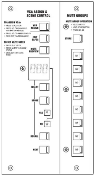
Snapshot VCA Recall On/Off
This is disabled by default as it is a potentially dangerous mode, particularly for normal rock and roll type applications, where the scene automation is not being used. Accidental pressing of the Recall or Next switches could then result in the current VCA assignments being unassigned during a performance, so this function is disabled. For theatrical applications it can be useful to have VCAs change their assignments with scene changes -if this is required VCA Recall can be enabled.
Snapshot Recall Mute Update On/Off
Normally, recalling scenes automatically recalls the stored mute settings, as well as sending out a midi program change message. However, there may be times when you want to send the midi program changes but NOT have the mutes continually being reset. Switching off the mute recall allows the scene control section to be used as a remote control for MIDI FX, without affecting console mutes.
Mute Groups remain fully operational when scene mute recall has been disabled.
Scene Recall MIDI Tx Program Change On/Off
In some circumstances it may be necessary to inhibit the sending of MIDI program changes when recalling scenes -for example, if program changes are not being used to recall patches on FX units, but channel mutes are being used to trigger sound FX samples, the program change may disrupt the operation of the sampler.
The following settings are saved to EPROM on power down and will be restored when the console is powered back up:
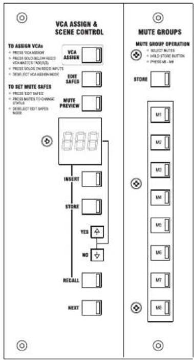
Active mutes
Manual mute status
Active Mute Groups (if User Mode 1 inactive)
Active VCA Groups
VCA Assign Membership
Active safes
Mute Group Shortcuts (if User Mode 1 active)
Output AFL 'pairing'
Last Recalled Scene
User Settings

CPU Reset
In order to change User Modes without powering the console down, or in the unlikely event of a CPU crash, it can be re-booted whilst the power is switched on. The scene, mute group and VCA assign memories will be unaffected by this procedure.
Press & hold EDIT SAFES + YES + NOEDIT SAFES + YES + NO
The CPU will be reset, and will follow the same boot-up sequence as when the console is powered up.
In the event of a serious CPU malfunction, it is possible to force the CPU to reboot by pressing an internal switch on the CPU pcb itself. This is accessible in an emergency by removing the screws holding the CPU fascia to the console, and carefully lifting the CPU assembly out of the console until the large CPU pcb, which lies flat at the bottom of the assembly, can be reached. The reset switch is visible on the top side of the board, towards the centre of the front edge of the pcb.
Hard Reset
Note: Before performing a Hard Reset, ensure that the scene memory has been backed up using a MIDI dump, as all saved data will be erased.
Press Store + RecallStorpowerperform a Hard Reset.
A hard reset clears out all saved data, restoring the 'factory defaults'. All scenes will be 'empty' (i.e. no mutes/VCA assignments), all mute groups will be 'empty', all User modes reset, all mutes/safes reset etc.

The console uses standard MIDI Sys-Ex protocol to allow saving and reloading of the scene memory to any MIDI device which can receive, save and transmit Sys-Ex data.
Transmitting a SysEx Dump
A Dump Out can be generated either by pressing, all at the same time YES, NO and Recall on the main panel, or by requesting a dump with a Dump Out Request Sys-Ex message.
During the Dump Out, the display will flash '_do'. 128 scene packets followed by a Mute Group Assignments packet will be transmitted.
Notes:
A Dump out can only be initialized when in normal mode (i.e. not scrolling/in Store/Insert modes), and will not be initialized if currently dumping in.
During Dump Out all scene/mode automation is disabled. On completing the dump, the console will return to normal operation, displaying the current scene as usual.
During a dump out, no MIDI mute messages will be transmitted, and any incoming MIDI messages will be ignored.
Receiving a SysEx Dump
For simplicity of operation, the console will automatically accept a dump in, when it receives valid data in the form of one of its own midi dumps. It will not respond to any other type of Sys-Ex dump.
On receiving a valid sysex packet, the MIDI Dump In will be carried out. The display will flash '_di' during the dump.
Each packet is received, decoded & checked, and if there are no checksum or other errors the data will be written to EEPROM. If there are problems an error message will be displayed.
The console will revert to normal operation if no further sysex message is received 1 second after receiving the previous sysex message.
During a dump in, no MIDI mute messages will be transmitted.
Notes:
Any packets can be received in any order.
On receiving a valid Dump Sysex Packet the console will enter Dump In mode.
Dump In mode won't be entered for a Dump Request SysEx.
A Dump In will be ignored if in Preview/SIP Active modes, or if currently dumping out.
The console has full linking capability with both audio and logic interfaces provided for connecting a second 'secondary' console when more input channels are required. (Note that only one additional console can be connected).
Audio Linking
Audio linking is accomplished by simply connecting the main outputs (group, aux, mix, solo etc) of the secondary console to the corresponding bus inputs of the primary console, using a female XLR to 1/4" jack multicore.
A 25-way multicore is required. The bus inputs are described earlier in the manual, in the description for the Dual Aux, Stereo Group and Main modules.
Logic Linking -VCAs, Mute Groups and Solos
A 15-way proprietary link cable is used to link the VCAs and other facilities.
This is not compatible with any previous Soundcraft consoles.
Linking of the VCAs is done using a parallel interface with VCA bus inputs on the TO PRIMARY connector, and outputs on the TO SECONDARY connector.
Primary/secondary designation will depend on which way the cable is connected:
i.e., connect TO PRIMARY of the secondary console to TO SECONDARY on the primary console.
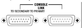
The Mute Groups, Solos and automation of two consoles are linked by means of an RS232 serial connection within the 15-wy proprietary link (referred to below as the 'Cascade Cable'), joining the internal CPUs of both consoles.
The consoles must be linked at boot up. The console checks for the presence of a cascade cable at its cascade port at boot-up. From this it determines whether it is a 'Primary standalone', 'Primary Cascadable', or 'Secondary Cascadable' console.
A link is automatically established when two consoles linked with a cascade cable are booted up. When the link is established the secondary console inherits the primary console's settings. The synced display will flash 'SLA' until synchronization with the primary console is (automatically) achieved.
Once linked, all Automation operation from the secondary console is disabled*, except for SIP, Auto Cancel, IP Priority & Solo Clear, which function mutually inclusively with the respective primary console controls. This means that solo control is global and can be activated from either the primary or secondary console. Automation behaviour is identical over cascaded consoles as for a standalone console.
*The one exception to this is for initiating a MIDI Dump Out - If UP, DN and Recall are pressed simultaneously on the secondary console, a (local) MIDI Dump Out will be initiated.
A link will not be established unless the primary console is in normal mode (i.e. not in Edit Safes/Preview/VCA Assign/SIP Active/Dump In/Dump Out mode). All active solos will be cleared on both consoles on establishing a link.
Link established: Synchronizing Console Settings
The secondary console now updates the seven-segment display to the same as the primary console. Any relevant mutes are activated for members of any active VCA Main Mutes (flashing), plus any relevant mutes are activated for members of any active Mute Groups.
The primary and secondary console are now fully synchronized, and are in Normal State, ready for operation.
The linked consoles now remain in a linked configuration with a hello call-reply handshake every 10s. If the handshake times-out, all solos will be cleared on both consoles, and the secondary console will return to normal mode (i.e. Edit Safes/Preview/VCA Assign will be exited). The secondary console will revert to displaying 'SLA', waiting for the link to be re-established. During this time, only mute and solo automation is available on the secondary console.
If a link is re-established, the secondary console once again inherits the primary console's settings as above, and cascaded console operation continues once again. If a link is not re-established within 30s, both consoles will revert to being an independent primary console with full automation independently per console. This is to allow access to all automation functions on each console in the case of emergency where the link has been permanently severed. A link can now not be re-established without re-booting both consoles and re-establishing a link.
Cascaded Operation
Once a link is established, all Scene, Mode, Mute Group and VCA Main Mute automation is carried out from the primary console. The following switches/LEDs on the secondary console will be unused at all times; i.e. depressing the switches will have no effect whatsoever, LEDs always half-brightness (except for initiating a MIDI Dump Out):
Edit Safes, VCA Assign, Preview
Insert, Store, Next, *UP, *DN, *Recall
MG Store, MG Mains 1-8
VCA Main Mutes, VCA Main Solos, VCA Main Levels
(*Exception: Pressing UP, DN and Recall simultaneously on the secondary console initiates a local MIDI Dump Out).
The 7 segment display on the secondary console always follows the primary console, except during MIDI Dumps, where the dumping console displays '_di 'or '_do', and the remote console displays '--'.
The solo automation controls, that is:
SIP, Auto Cancel, IP Priority, Solo Clear
are still active on both primary and secondary consoles. These features will function globally over both consoles, allowing solo control to be activated from either console. The solo automation controls hence are always kept consistent with each other over both consoles, i.e. activating the SIP switch on the primary console will also invoke the secondary console to enter relevant SIP mode and to light it's SIP LED etc.
User Modes over cascaded consoles
User modes can be configured independently per console. However, inherently, User Modes 1 (Mute Groups Recall Scenes), 5 (Program Change Tx OFF) and 6 (Recall Auto Increment) will have no affect on the secondary console.
Solo Modes over cascaded consoles
The solo mode (Normal, Input Priority, Input Priority + Auto Cancel, Auto Cancel) functions globally over both consoles. For instance, when Auto Cancel + Input Priority is On, Activating an input solo on the secondary console will cancel any other input solos on the secondary console plus cancel any input solos on the primary console.
Mute Group Operation over cascaded consoles
All Mute Group automation is carried out from the primary console. Relevant messages are automatically sent to the secondary console invoking the secondary console to update its settings to maintain synchronicity with the primary console.
The Mute Group Main switches on the secondary console are disabled.
VCA Main Mute/Solo over cascaded consoles
All VCA Main automation is carried out from the primary console. Relevant messages are automatically sent to the secondary console invoking the secondary console to update its settings to maintain synchronicity with the primary console.
The VCA Main switches on the secondary console are disabled.
Scene Automation over cascaded consoles
All Scene automation (Scene UP, DN, Recall, Next, Store, Insert) is carried out from the primary console. Relevant messages are automatically sent to the secondary console invoking the secondary console to update its settings to maintain synchronicity with the primary console.
Mode Switching over cascaded consoles
All mode switching (Edit Safes, Preview, VCA Assign) is carried out from the primary console. Relevant messages are automatically sent to the secondary console invoking the secondary console to update its settings to maintain synchronicity with the primary console.
MIDI Dumping over cascaded consoles
MIDI Dump
MIDI Dump (In/Out) will function locally for each console, ie the memory of each console remains separate, and both must be backed up separately.
When a console (primary or secondary) enters a MIDI dump (In/Out), a message is automatically sent to the other console, invoking it to enter MIDI Suspend state. In this state, all scene/mode automation is disabled plus the display shows '---'. When the console finishes dumping, a message is automatically sent to the other console, invoking it to exit MIDI Suspend state, returning to normal console operation.
MIDI Implementation over cascaded consoles
MIDI Mutes
The MIDI Mute implementation functions locally for each console.
Any MIDI mutes received at the console's MIDI In port will locally activate/deactivate mutes as usual.
All MIDI mutes associated with manual mute activation/deactivation will be transmitted via the local MIDI Out port as usual.
Scene Program Changes
The MIDI Program Change implementation functions only on the primary console.
Any MIDI program changes received at the primary console's MIDI In port will recall scenes as usual.
Any MIDI program changes associated with scene recall (unless User Mode 5 active) will be transmitted by the primary console's MIDI Out port.
Any MIDI program changes received at the secondary console's MIDI In port will by ignored.
No MIDI program changes associated with scene recall will ever be transmitted by the secondary console.
Dbx Driverack 480 AFL Protocol Solos
The Dbx Driverack 480 AFL implementation functions locally for each console.
Any MIDI solo messages received at the console's MIDI In port will locally activate/deactivate AFL solos as usual.
All MIDI solo messages associated with manual solo activation/deactivation will be transmitted via the local MIDI Out port as usual.
BSS Varicurve MIDI Loop Mode
The BSS MIDI Loop AFL implementation functions locally for each console.
Specifications
| MH4 Specification | |
| Frequency Response | XLR input to any output: +0/-0.5dB, 20Hz - 20kHz |
| T.H.D. and Noise | All measurements at +10dBu.XLR In to Direct Out <0.015% @ 1kHz<0.02% @ 10kHzXLR In to Mix Out <0.015% @ 1kHz<0.02% @ 10kHz |
| Mic Input E.I.N. | 22Hz - 22kHz bandwidth, unweighted: < -128 dBu (150Ω source) |
| Residual Noise | Mix Output; no inputs routed, Mix fader @ 0dB: -90dBu |
| Bus Noise | Mix Output; 48 channels routed, input faders @ -∞ , Mix fader 0dB: < -84dBuGrp Output; 48 channels routed, input faders @ -∞ , Grp fader 0dB: < -84dBuAux Output; 48 channels routed, input sends @ -∞ , Grp fader 0dB: < -85dBu |
| Crosstalk | 1kHz, +20dBu input signalsInput Channel muting: >100dBInput fader cutoff: >100dBInput pan pot isolation: >70dBMix routing isolation: >100dBGroup routing isolation: >88dBGroup-group crosstalk: < -90dBGroup-Mix crosstalk: < -100 dBMix-group crosstalk: < -95 DBAux send off: < -88 dB |
| CMRR | Mono Input -85 dB @ 1kHz |
| Oscillator | 63Hz to 10kHz/Pink Noise, variable level. |
| HP Filter (Mono Input) | 30-400Hz, 12dB/octave. |
| EQ (Mono Input) | HF: 1.2k-20kHz, +/-15dB, shelvingHi-Mid: 750 - 12kHz, +/-15dB, Q = 0.5 - 3.0Lo-Mid: 75 - 1.2kHz, +/-15dB, Q = 0.5 - 3.0LF: 35 - 550Hz, +/-15dB, shelving |
| Metering | Overbridge: 8 VU Meters monitoring Group/Aux/Matrix+ 3 VU Meters monitoring Left Mix/AFL/PFL, Right Mix/AFL/PFL & Mono (centre) MixEach meter has a peak LED set to 6db below clipping.Mono & Stereo Inputs: 12-LED bargraph + Peak LED |
| Power Consumption | Mains Power: 56ch - 600VA max, 24ch: 300VA max48 Ch Console: each 17V rail takes 6.5 A (nominal)(measured without Littlites connected)the 8V rail takes 0.5 A (nominal). |
| Weight | 24 Ch -76kg (168 lb), 32 Ch - 89kg (196 lb), 40 Ch - 102kg (225 lb),48Ch - 115kg (254 lb), 56Ch - 128kg (282 lb). |
| Operating ConditionsTemperature RangeRelative Humidity | -10°C to +30°C0% to 80% |
| MH4 Specification | |||||||
| Module | Signal | Conn. | Pin | Nom Level | Max Level | Impedance | |
| Inputs | Mono Input | Input (A & B) | Female XLR | Pin 1 - Ground Pin 2 - Signal Hot Pin 3 - Signal Cold | -50 to -15dBu -30 to +5dBu (switched range) | +26dBu | 2kΩ |
| Stereo Input | STE IN (Left & Right) | Female XLR | -50 to -15dBu -30 to +5dBu (switched range) | +26dBu | >2kΩ | ||
| Matrix & Bus linking Inputs | Ext. In | TRS (1/4" Jack) | Tip - Signal Hot Ring - Signal Cold Sleeve - Ground | 0dBu | +21dBu | >10kΩ | |
| Master | TB Mic I/P | Female XLR | Pin 1 - Ground Pin 2 - Signal Hot Pin 3 - Signal Cold | -50 to 0dBu | 0dBu | 2kΩ | |
| EXT TB I/P | Female XLR | Pin 1 - Ground Pin 2 - Signal Hot Pin 3 - Signal Cold | +0dBu | +21dBu | >10kΩ | ||
| 2-TK Returns (L & R) | Female XLR | Pin 1 - Ground Pin 2 - Signal Hot Pin 3 - Signal Cold | 0dBu | +26dBu/+12dBV | >10kΩ | ||
| Insert points | Mono Input | Channel Snd & Ret | TRS (1/4" Jack) | Tip - Signal Hot Ring - Signal Cold Sleeve - Ground | Send 0dBu Return 0dBu | +21dBu (into 2kΩ) +21dBu | Send <75Ω Return >15kΩ |
| Stereo Input (L&R) | Channel Snd & Ret | Send <75Ω Return >15kΩ | |||||
| Matrix | Matrix Snd & Ret | Send 0dBu Return 0dBu | +21dBu +21dBu | Send <75 Return >15k | |||
| Group/Aux Master | Group/Aux Snd & Ret | Send 0dBu Return 0dBu | +21dBu (into 2kΩ) +21dBu | Send <75Ω Return >15kΩ | |||
| Output Master | Main Mono, L & R Snd & Ret | Send <75Ω Return >15kΩ | |||||
| Outputs | Mono Input | Direct Output | Male XLR | Pin 1 - Ground Pin 2 - Signal Hot Pin 3 - Signal Cold | 0dBu | +21dBu (into 2kΩ) | <75Ω |
| Matrix | Matrix Output | Male XLR | 0dBu | +21dBu (into 2kΩ) | <75Ω | ||
| Group/Aux Master | Group/Aux Output | Male XLR | +0dBu | +21dBu (into 2kΩ) | <75Ω | ||
| L/R/Mono/ Alt L&R Outputs | Male XLR | 0dBu | +21dBu (into 2kΩ) | <75Ω | |||
| Output Master | Ext TB Output | Male XLR | 0dBu | +21dBu (into 2kΩ) | <75Ω | ||
| Oscillator Output | Male XLR | 0dBu | +21dBu (into 2kΩ) | <75Ω | |||
| Headphones Output | TRS (1/4" Jack) | Tip - Left Ring - Right Sleeve - Ground | 0dBu | +20dBu (into 600Ω) 0dBu (into 8Ω) | 50Ω | ||
| Monitor Outputs L & R | Male XLR | Pin 1 - Ground Pin 2 - Signal Hot Pin 3 - Signal Cold | 0dBu | +21dBu (into 2kΩ) | <75Ω | ||
| Record Outputs L & R | RCA Phono | Inner - Signal Hot Outer - Ground | -10dBV | +21dBu (into 2kΩ) | <75Ω | ||
| Solo Outputs L & R | Male XLR | Pin 1 - Ground Pin 2 - Signal Hot Pin 3 - Signal Cold | 0dBu | +21dBu (into 2kΩ) | <75Ω | ||
Appendix 1: MIDI Implementation
Because of special MIDI merge functionality required for interfacing to a BSS Varicurve, on booting up, the console will check if it is installed as part of a BSS Varicurve MIDI loop. It will determine this by checking for the BSS Varicurve sysex request message, which is transmitted every 200ms from the BSS Varicurve unit:
If it detects this message on boot up, it will enter BSS Varicurve MIDI loop mode. If it does not detect this message on boot up, it will enter Normal MIDI mode. Normal MIDI mode is usually therefore the default mode.
BSS Varicurve MIDI Loop Mode
If a BSS Varicurve is detected, the console switches to this mode. The object is to enable the console AFL switches on output modules to remotely change the EQ page on the Varicurve remote, so as to ensure the correct EQ is always being viewed/adjusted and listened to.
When in this mode, no MIDI messages associated with automation are transmitted/responded to, plus MIDI dump in/out is disabled. ALL data that is received by the console will be throughput straight to the MIDI output port, EXCEPT the BSS sysex request:
which will be REPLACED with the message
F0 00 20 18 7F 20 AFL F7
where AFL = last output AFL soloed (0x000x1C for output solos 128)
or = 0x7F if no output has been solod since the last BSS sysex request was serviced.
This allows the BSS Varicurve unit to update its display to show the last solod AFL. Attempting to install the console into a BSS Varicurve MIDI loop after the console has booted will not work the console must detect the presence of a BSS Varicurve MIDI loop on boot up.
Normal MIDI Mode
If a BSS Varicurve MIDI loop is not detected on boot up, it will process/transmit MIDI automation data as normal.
The MIDI Channel for Transmit & Receive is fixed at channel 16. Running status is also supported for Rx. There are two modes: Sampler (default) & Sequencer Mode. This can be set by User Mode 2 on Boot-up.
MUTES
A MIDI mute On message will be transmitted on manually muting any channel A MIDI Mute Off message will be transmitted on manually unmuting a channel
MIDI Mute RxMIDI Mute Rx
A received MIDI mute On message will mute a channel IF the channel was previously unmuted AND the channel is not safed. A received MIDI mute Off message will unmute a channel IF the channel was previously muted due to a scene or MIDI mute only.
Sampler ModeSampler Mode
This is called sampler mode because the Note format allows Samplers to play samples triggered by the Mute going Off. These events are NOT easily viewed recorded into a sequencer. The transmit & Receive message format is:
Pressing Mute switches transmit Note On (for Mute Off) or Note Off (for Mute On) messages, whose velocity determines the Mute state. The message format is:
where
| <Console Channel> = 00H-07H | Mono Input 1 - 8 |
| = 08H-0FH | Mono Input 9 - 16 |
| = 10H-17H | Mono Input 17 - 24 |
| = 18H-1FH | Mono Input 25 - 32 |
| = 20H-27H | Mono Input 33 - 40 |
| = 28H-2FH | Mono Input 41 - 48 |
| = 30H-37H | Mono Input 49 - 56 |
| = 38H-3FH | Aux 1 - 8 |
| = 48H-4FH | Groups 1 - 8 |
| = 48H-4FH | Matrix Main 1 - 8 Stereo |
| = 50H-57H | Input 1-4, unused |
| <Velocity> = | 7F |
The velocity is ignored on Rx i.e. any velocity will trigger the mute.
Sequencer Mode Sequencer Mode
This is called sequencer mode because the Note format allows the events to be viewed more easily when recorded into a sequencer. Pressing Mute switches transmits Note On messages whose velocity determines the Mute state. MIDI messages always transmitted when a mute is pressed. The transmit & Receive message format is:
where
| <Note On> = 9FH (i.e. Note On, MIDI Channel 16) |
| <Console Channel> = (see above) |
| <Velocity> = 3F if Mute is OFF= 7F if Mute is ON |
For Rx, any velocity less than 3F is interpreted as a Mute OFF. Any velocity higher than 3F is interpreted as a Mute ON.
Mute Groups
Activating/deactivating a Mute Group transmits no MIDI mute data for any associated changes in mute status.
VCA Main Mutes
Activating/deactivating a VCA Main Mute transmits no MIDI mute data for any associated changes in mute status.
Safe On/Off
Activating/deactivating Safe On/Off transmits no MIDI mute data for any associated changes in mute status.
Scene Associated MutesScene Associated Mutes
Recalling a scene transmits no MIDI mute data for any associated changes in mute status.
SIP Associated Mutes SIP Associated Mutes
Activating/deactivating a SIP Mute transmits no MIDI mute data.
SOLOs
MIDI Solo RxMIDI Solo Rx
On reception of the message (from a dbx Driverack 480 unit)
F0 39 04 7F 20 AFL F7
where
AFL = output AFL (0x000x1C for output solos 128)
or
= 0x7F (Solo Clear)
the relevant AFL solo/Solo Clear will be activated.
MIDI Solo TxMIDI Solo Tx
When an output solo is pressed, a sysex message directed to a dbx Driverack 480 unit is transmitted. This is transmitted in the form:
F0 00 01 1E 7F 7F 20 AFL F7
where
AFL=output AFL solod (0x000x1C for output solos 128),
or
= 0x7F if last remaining solod output solo is unsolod
No message is transmitted on pressing an input solo/VCA solo. A message will not be transmitted if the solo was activated via an incoming Driverack message.
SCENES
Recalling a Scene will transmit a Program Change Message, unless User Setting 5 (Snapshot Recall MIDI Tx Program Change Off) is active. The message format is:
where
i.e. Snapshot numbers 1 to 128 are mapped to Program Change numbers 0–127. Reception of these MIDI messages will recall the relevant internal scenes.
A secondary console never responds to/transmits Program Changes. This is all controlled by the primary console in a cascaded configuration.
A program change message will not be transmitted if the scene recall occurred on reception of a program change message.
SYS-EX DUMPS
For backup purposes the contents of the scene memory plus current VCA assignments can be dumped and reloaded via midi sys-ex bulk dumps.
The general SysEx format is as follows:
F0 <header> <data payload><checksum> F7
<header> consists of
<Soundcraft ID> 39h
<Product ID> 04h S3 console ID
<Version Maj> i.e. the 2 in V2.01 Build 009
<Version Min> i.e. the 0 in V2.01 Build 009
<Version Min L> i.e. the 1 in V2.01 Build 009
<Packet ID LSB> 00h 7Fh See Table
<Packet ID MSB> 00h 01h See Table
This consists of a 7-bitised form of the Scene or Mute Groups data held in EEPROM. There is no data payload if the packet ID is a Dump Request.
| Description | ||
| 00h 00-7Fh Scenes 1-128 | ||
| 01h | 00h | Mute Groups |
| 01h Dump Request | ||
Appendix2: Mark-up Sheets
To assist you in restoring the console to a previous setting you may copy these sheets as many times as you like, and use the copies to make a note of your control settings.
Mono Inputs
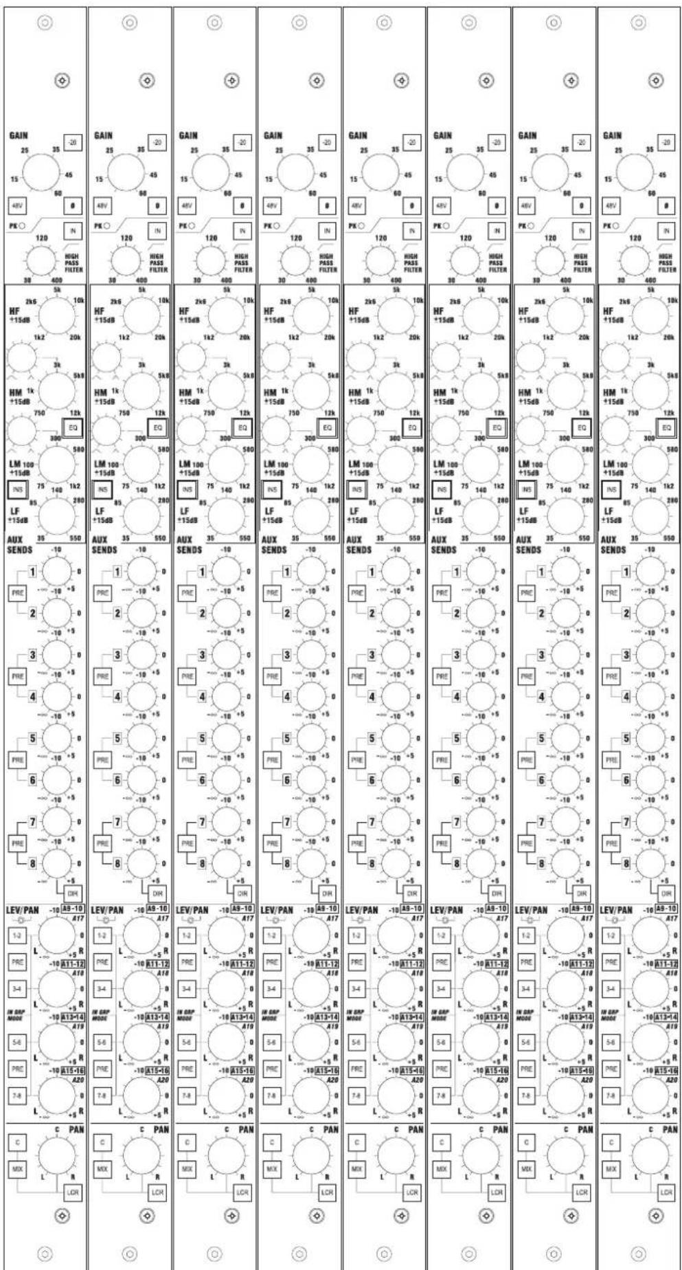
Mono Input Faders

Stereo Inputs


Outputs
| MATRIX SENDS-10M1-10M2-10M3-10M4-10M5-10M6-10M7-10M8-10M9-10M10-10M11-10M12-10M13-10M14-10M15-10M16-10M17-10M18-10M19-10M20-10M21-10M22-10M23-10M24-10M25-10M26-10M27-10M28-10M29-10M30-10M31-10M32-10M33-10M34-10M35-10M36-10M37-10M38-10M39-10M40-10M41-10M42-10M43-10M44-10M45-10M46-10M47-10M48-10M49-10M50-10M51-10M52-10M53-10M54-10M55-10M56-10M57-10M58-10M59-10M60-10M61-10M62-10M63-10M64-10M65-10M66-10M67-10M68-10M69-10M70-10M71-10M72-10M73-10M74-10M75-10M76-10M77-10M78-10M79-10M80-10M81-10M82-10M83-10M84-10M85-10M86-10M87-10M88-10M89-10M90-10M91-10M92-10M93-10M94-10M95-10M96-10M97-10M98-10M99-10M100-10M101-10M102-10M103-10M104-10M105-10M106-10M107-10M108-10M109-10M110-10M111-10M112-10M113-10M114-10M115-10M116-10M117-10M118-10M119-10M120-10M121-10M122-10M123-10M124-10M125-10M126-10M127-10M128-10M129-10M130-10M131-10M132-10M133-10M134-10M135-10M136-10M137-10M138-10M139-10M140-10M141-10M142-10M143-10M144-10M145-10M146-10M147-10M148-10M149-10M150-10M151-10M152-10M153-10M154-10M155-10M156-10M157-10M158-10M159-10M160-10M161-10M162-10M163-10M164-10M165-10M166-10M167-10M168-10M169-10M170-10M171-10M172-10M173-10M174-10M175-10M176-10M177-10M178-10M179-10M180-10M181-10M182-10M183-10M184-10M185-10M186-10M187-10M188-10M189-10M190-10M191-10M192-10M193-10M194-10M195-10M196-10M197-10M198-10M199-10M200-10M201-10M202-10M203-10M204-10M205-10M206-10M207-10M208-10M209-10M210-10M211-10M212-10M213-10M214-10M215-10M216-10M217-10M218-10M219-10M220-10M221-10M222-10M223-10M224-10M225-10M226-10M227-10M228-10M229-10M230-10M231-10M232-10M233-10M234-10M235-10M236-10M237-10M238-10M239-10M240-10M241-10M242-10M243-10M244-10M245-10M246-10M247-10M248-10M249-10M250-10M251-10M252-10M253-10M254-10M255-10M256-10M257-10M258-10M259-10M260-10M261-10M262-10M263-10M264-10M265-10M266-10M267-10M268-10M269-10M270-10M271-10M272-10M273-10M274-10M275-10M276-10M277-10M278-10M279-10M280-10M281-10M282-10M283-10M284-10M285-10M286-10M287-10M288-10M289-10M290-10M291-10M292-10M293-10M294-10M295-10M296-10M297-10M298-10M299-10M300-10M301-10M302-10M303-10M304-10M305-10M306-10M307-10M308-10M309-10M310-10M311-10M312-10M313-10M314-10M315-10M316-10M317-10M318-10M319-10M320-10M321-10M322-10M323-10M324-10M325-10M326-10M327-10M328-10M329-10M330-10M331-10M332-10M333-10M334-10M335-10M336-10M337-10M338-10M339-10M340-10M341-10M342-10M343-10M344-10M345-10M346-10M347-10M348-10M349-10M350-10M351-10M352-10M353-10M354-10M355-10M356-10M357-10M358-10M359-10M360-10M361-10M362-10M363-10M364-10M365-10M366-10M367-10M368-10M369-10M370-10M371-10M372-10M373-10M374-10M375-10M376-10M377-10M378-10M379-10M380-10M381-10M382-10M383-10M384-10M385-10M386-10M387-10M388-10M389-10M390-10M391-10M392-10M393-10M394-10M395-10M396-10M397-10M398-10M399-10M400-10M401-10M402-10M403-10M404-10M405-10M406-10M407-10M408-10M409-10M410-10M411-10M412-10M413-10M414-10M415-10M416-10M417-10M418-10M419-10M420-10M421-10M422-10M423-10M424-10M425-10M426-10M427-10M428-10M429-10M430-10M431-10M432-10M433-10M434-10M435-10M436-10M437-10M438-10M439-10M440-10M441-10M442-10M443-10M444-10M445-10M446-10M447-10M448-10M449-10M450-10M451-10M452-10M453-10M454-10M455-10M456-10M457-10M458-10M459-10M460-10M461-10M462-10M463-10M464-10M465-10M466-10M467-10M468-10M469-10M470-10M471-10M472-10M473-10M474-10M475-10M476-10M477-10M478-10M479-10M480-10M481-10M482-10M483-10M484-10M485-10M486-10M487-10M488-10M489-10M490-10M491-10M492-10M493-10M494-10M495-10M496-10M497-10M498-10M499-10M500-10M501-10M502-10M503-10M504-10M505-10M506-10M507-10M508-10M509-10M510-10M511-10M512-10M513-10M514-10M515-10M516-10M517-10M518-10M519-10M520-10M521-10M522-10M523-10M524-10M525-10M526-10M527-10M528-10M529-10M530-10M531-10M532-10M533-10M534-10M535-10M536-10M537-10M538-10M539-10M540-10M541-10M542-10M543-10M544-10M545-10M546-10M547-10M548-10M549-10M550-10M551-10M552-10M553-10M554-10M555-10M556-10M557-10M558-10M559-10M560-10M561-10M562-10M563-10M564-10M565-10M566-10M567-10M568-10M569-10M570-10M571-10M572-10M573-10M574-10M575-10M576-10M577-10M578-10M579-10M580-10M581-10M582-10M583-10M584-10M585-10M586-10M587-10M588-10M589-10M590-10M591-10M592-10M593-10M594-10M595-10M596-10M597-10M598-10M599-10M600-10M601-10M602-10M603-10M604-10M605-10M606-10M607-10M608-10M609-10M610-10M611-10M612-10M613-10M614-10M615-10M616-10M617-10M618-10M619-10M620-10M621-10M622-10M623-10M624-10M625-10M626-10M627-10M628-10M629-10M630-10M631-10M632-10M633-10M634-10M635-10M636-10M637-10M638-10M639-10M640-10M641-10M642-10M643-10M644-10M645-10M646-10M647-10M648-10M649-10M650-10M651-10M652-10M653-10M654-10M655-10M656-10M657-10M658-10M659-10M660-10M661-10M662-10M663-10M664-10M665-10M666-10M667-10M668-10M669-10M670-10M671-10M672-10M673-10M674-10M675-10M676-10M677-10M678-10M679-10M680-10M681-10M682-10M683-10M684-10M685-10M686-10M687-10M688-10M689-10M690-10M691-10M692-10M693-10M694-10M695-10M696-10M697-10M698-10M699-10M700-10M701-10M702-10M703-10M704-10M705-10M706-10M707-10M708-10M709-10M710-10M711-10M712-10M713-10M714-10M715-10M716-10M717-10M718-10M719-10M720-10M721-10M722-10M723-10M724-10M725-10M726-10M727-10M728-10M729-10M730-10M731-10M732-10M733-10M734-10M735-10M736-10M737-10M738-10M739-10M740-10M741-10M742-10M743-10M744-10M745-10M746-10M747-10M748-10M749-10M750-10M751-10M752-10M753-10M754-10M755-10M756-10M757-10M758-10M759-10M760-10M761-10M762-10M763-10M764-10M765-10M766-10M767-10M768-10M769-10M770-10M771-10M772-10M773-10M774-10M775-10M776-10M777-10M778-10M779-10M780-10M781-10M782-10M783-10M784-10M785-10M786-10M787-10M788-10M789-10M790-10M791-10M792-10M793-10M794-10M795-10M796-10M797-10M798-10M799-10M800-10M801-10M802-10M803-10M804-10M805-10M806-10M807-10M808-10M809-10M810-10M811-10M812-10M813-10M814-10M815-10M816-10M817-10M818-10M819-10M820-10M821-10M822-10M823-10M824-10M825-10M826-10M827-10M828-10M829-10M830-10M831-10M832-10M833-10M834-10M835-10M836-10M837-10M838-10M839-10M840-10M841-10M842-10M843-10M844-10M845-10M846-10M847-10M848-10M849-10M850-10M851-10M852-10M853-10M854-10M855-10M856-10M857-10M858-10M859-10M860-10M861-10M862-10M863-10M864-10M865-10M866-10M867-10M868-10M869-10M870-10M871-10M872-10M873-10M874-10M875-10M876-10M877-10M878-10M879-10M880-10M881-10M882-10M883-10M884-10M885-10M886-10M887-10M888-10M889-10M890-10M891-10M892-10M893-10M894-10M895-10M896 |
Main

VCA Main Faders

- CPS800
- BLOCK DIAGRAMS 3 - 1
- CONSOLE OPERATION 4 - 1
- AUTOMATION 5 - 1
- SPECIFICATIONS 6 - 1
- INTRODUCTION
- THE KEY FEATURES OF THE MH4 ARE
- INSTALLATION
- GENERAL PRECAUTIONS
- HANDLING AND TRANSPORT
- POWER SUPPLIES & CABLES
- SIGNAL LEVELS
- GENERAL WIRING PROCEDURES
- INITIAL WIRING CONSIDERATIONS
- AUDIO WIRING
- SHIELDING
- POINTS TO REMEMBER
- BLOCK DIAGRAMS
- MONO INPUT
- CONSOLE OPERATION
- GAIN
- PHANTOM POWER
- 20DB
- PEAK LED
- PHASE
- HI-PASS
- EQ
- INSERT POINT
- INS SWITCH
- MONO AUX SENDS
- PRE SWITCHES
- DIR SWITCH
- DIRECT OUTPUT
- GROUPS AND STEREO AUX SENDS
- GLOBAL GRP MODE NOT SELECTED ('MONITOR' MODE)
- GLOBAL GRP MODE SELECTED ('FOH' MODE)
- ROUTING TO MIX BUSSES
- LCR PANNING
- FADER
- MUTE
- SAFE/PREV
- METER
- VCA ASSIGN LEDS
- SOLO
- SOLDER LINK OPTIONS
- REAR CONNECTORS
- MONO L
- MONO R
- HIGH-PASS FILTER
- BALANCE
- NOTE
- SOLDERLINK OPTIONS
- OUTPUT SECTION - OVERVIEW
- AUX INSERT POINT (ON REAR PANEL)
- EXTERNAL INPUT
- SAFE/PREV LED
- AFL
- ROUTING TO THE MIX
- TB/OSC
- METERS
- MATRIX SENDS
- MATRIX SECTION
- SENDS
- MATRIX MAIN FADER
- MATRIX INSERT POINT
- THE EXTERNAL INPUT
- GROUP/AUX INSERT POINT (ON REAR PANEL)
- MIX SWITCH
- AUX MAIN AUX 9-12 OUTPUTS
- GLOBAL SWITCHING
- VCA MAIN FADER
- VCA MUTE
- VCA SOLO & ASSIGNING VCAS
- MAIN OUTPUTS
- FADERS
- FADER TO MONITORS
- INSERT POINTS
- ALT MIX OUTPUT
- PRE
- MNO
- EXTERNAL INPUTS
- TALKBACK
- INT
- EXT
- CALL
- OSCILLATOR
- PSU STATUS INDICATORS
- LAMP DIMMER
- MONITOR AND HEADPHONES OUTPUTS
- MNO L & R
- PHONES SOCKET
- SIGNAL SOURCES
- 2 TRACK REPLAY
- INPUT
- OUTPUT
- PFL & AFL
- SOLO IN PLACE
- SIP
- PFL/AFL TRIM
- SOLO CLEAR
- AUTO CANCEL
- INPUT PRIORITY
- VCA SOLO
- CONSOLE LINKING
- ILLUMINATION
- RECALIBRATION
- AUTOMATION
- ASSIGNMENT CONTROLS
- VCA ASSIGN
- EDIT SAFES
- MUTE PREVIEW
- REAR PANEL
- MUTE GROUP MAIN SWITCHES
- MUTE GROUP MAINS IN MUTE GROUPS MODE (DEFAULT MODE)
- MUTE GROUP MAINS AS SCENE 'SHORTCUTS' (USER MODE 1 - MUTE GROUP MAINS AS SCENE SHORTCUTS - ACTIVE)
- SCENE AUTOMATION
- 7-SEGMENT DISPLAY
- YES/ NO (↑/↓) SWITCHES
- RECALL SWITCH
- NEXT SWITCH
- STORE SWITCH
- INSERT SWITCH
- MODE FUNCTION FACTORY DEFAULT
- APPLICATION NOTES
- MUTE GROUP MAINS AS SCENE SHORTCUTS ON/OFF
- MIDI NOTE MODE - SEQUENCER/SAMPLER
- SNAPSHOT VCA RECALL ON/OFF
- SNAPSHOT RECALL MUTE UPDATE ON/OFF
- SCENE RECALL MIDI TX PROGRAM CHANGE ON/OFF
- CPU RESET
- HARD RESET
- TRANSMITTING A SYSEX DUMP
- NOTES
- RECEIVING A SYSEX DUMP
- AUDIO LINKING
- LOGIC LINKING -VCAS, MUTE GROUPS AND SOLOS
- LINK ESTABLISHED: SYNCHRONIZING CONSOLE SETTINGS
- CASCADED OPERATION
- USER MODES OVER CASCADED CONSOLES
- SOLO MODES OVER CASCADED CONSOLES
- MUTE GROUP OPERATION OVER CASCADED CONSOLES
- VCA MAIN MUTE/SOLO OVER CASCADED CONSOLES
- SCENE AUTOMATION OVER CASCADED CONSOLES
- MODE SWITCHING OVER CASCADED CONSOLES
- MIDI DUMPING OVER CASCADED CONSOLES
- MIDI DUMP
- MIDI IMPLEMENTATION OVER CASCADED CONSOLES
- MIDI MUTES
- SCENE PROGRAM CHANGES
- DBX DRIVERACK 480 AFL PROTOCOL SOLOS
- BSS VARICURVE MIDI LOOP MODE
- SPECIFICATIONS
- APPENDIX 1: MIDI IMPLEMENTATION
- NORMAL MIDI MODE
- MUTES
- SAMPLER MODESAMPLER MODE
- SEQUENCER MODE SEQUENCER MODE
- MUTE GROUPS
- VCA MAIN MUTES
- SOLOS
- SCENES
- SYS-EX DUMPS
- APPENDIX2: MARK-UP SHEETS
- MONO INPUT FADERS
- STEREO INPUTS
- VCA MAIN FADERS
Brand : SOUNDCRAFT
Model : MH4
Category : Audio Mixer