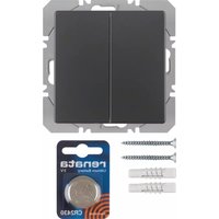
85656226 - Interrupteur mural radio HAGER - Free user manual and instructions
Find the device manual for free 85656226 HAGER in PDF.


| Product Type | Electrical Component (Modular Device) |
| Brand | Hager |
| Model | 85656226 |
| Dimensions (H x W x D) | Approx. 80 x 18 x 70 mm (modular) |
| Weight | Approx. 100 g |
| Rated Voltage | 230/400 V AC |
| Rated Current | 16 A (typical for modular devices) |
| Frequency | 50/60 Hz |
| Number of Modules (DIN) | 1 module (18 mm) |
| Main Functions | Overcurrent protection, short-circuit protection, isolation |
| Installation | Snap-on mounting on DIN rail EN 60715 |
| Terminal Capacity | Up to 16 mm² |
| Tripping Characteristics | B or C curve (typical) |
| Operating Temperature | -5°C to +40°C |
| Degree of Protection | IP20 |
| Mechanical Endurance | 20,000 cycles minimum |
| Electrical Endurance | 10,000 cycles minimum |
| Maintenance | No regular maintenance required; check operation periodically |
| Safety | Complies with IEC 60898 |
| Spare Parts & Repairability | Non-repairable, replace unit if faulty |
| Certifications | CE, VDE, UKCA (typical) |
| Country of Origin | Germany (typical for Hager) |
Frequently Asked Questions - 85656226 HAGER
User questions about 85656226 HAGER
0 question about this device. Answer the ones you know or ask your own.
Ask a new question about this device
Download the instructions for your Interrupteur mural radio in PDF format for free! Find your manual 85656226 - HAGER and take your electronic device back in hand. On this page are published all the documents necessary for the use of your device. 85656226 by HAGER.
USER MANUAL 85656226 HAGER
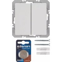
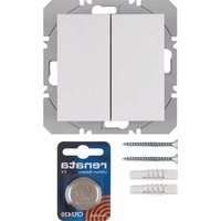
KNX radio wall-transmitter 1gang/2gang flat quicklink
Order no.: 8565 x2 xx
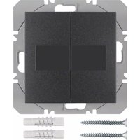
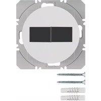
KNX radio wall-transmitter 1gang/2gang flat solar quicklink
Order no.: 8565 x1 xx
Operating instructions
1. Safety instructions
Electrical equipment may only be installed and assembled by a qualified electrician in accordance with the relevant installation standards, guidelines, regulations, directives, safety and accident prevention regulations of the country.
Failure to comply with these instructions may result in damage to the device, fire or other hazards.
Button cells do not belong in children's hands! If button cells are swallowed, seek immediate medical assistance.
Danger of explosion! Do not throw batteries in fire.
Danger of explosion! Do not recharge batteries.
The radio transmission is not suitable for safety or alarm applications.
These instructions are an integral component of the product and must be retained by the end user.
2. Design and layout of the device
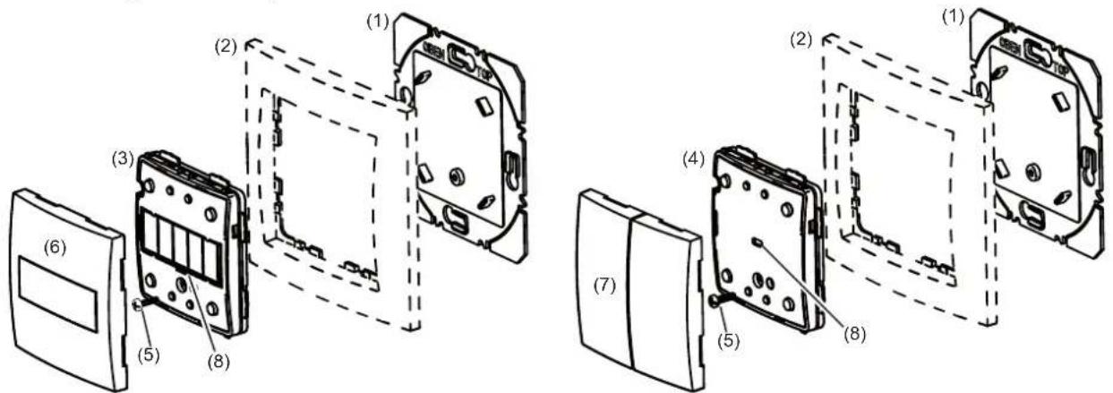
Figure 1: Design and layout of the device
(1) Supporting plate
(2) Frame (not within scope of delivery)
(3) Exemplarily Radio wall-transmitter 1gang flat solar quicklink
(4) Exemplarily Radio wall-transmitter 2gang flat quicklink
(5) Screw for dismantling protection
(6) Button design cover 1gang
(7) Button design cover 2gang
(8) Transmission status LED
3. Function
System information
This device is a product of the quicklink system, in which installation devices communicate via radio signals.
Quicklink stands for a configuration mode in which the function-related connection between transmitters and receivers is set on the device through buttons and displays without further tools.
All devices configurable by quicklink can be operated together in one system.
This device complies with the R&TTE directive 1999/5/EG. The declaration of conformity and further system information can be found on our internet site www.berker.de.
The device may be operated in all EU and EFTA states.
Correct use
– Flat surface installation and extension of combinations.
- Only suitable for use in indoor areas with no drip and no spray water.
- The device has been laid out for smaller applications in which a maximum 20 devices are allocated.
Product characteristics
– Functions for remote control, scenes, control switches via radio signals.
- Transmission status LED as display of radio reception; as required, when battery is too weak or a configuration is absent.
4. Operation
Allotting of channels to inputs of wall-transmitter
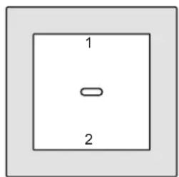
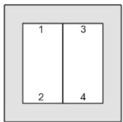
Figure 2: Allotting of channels to inputs
Transmit radio command
The push-button operation areas are freely configurable; operation is dependent on the configuration (Table 3).
■ Press a push-button operation area, e.g. 1, to send a radio command.
The transmission status LED (8) lights up to confirm.
Transmission status LED display
After operation, the transmission status LED on the 1gang wall-transmitter lights up through a lens and on the 1gang wall-transmitter and on the 2gang wall-transmitter, through the gap between the two push-buttons.
| Transmission status LED Severity | |
| Blinking orange Button not configured | |
| Blinking green / blinking green Radio command sent / radio command received | |
| 1 x blinking green Radio command sent to timer | |
| 1 x blinking green / 1 x blinking red | Radio command sent / radio command not received (with at least 1 device) |
| Red, flickering for 2 seconds Battery weak; replace | |
Table 1
5. Information for electricians
Overview of the operating elements beneath the design cover

Figure 3: Wall-transmitter with battery

Figure 4: Wall-transmitter solar
(9) Press-activation point of the push-button operation area
(10) cfg input with cfg LED or transmission status LED
(11) Solar cells
5.1 Installation
Selecting installation location
An average daily brightness of approx. 300 lux for 6 hours at the operation site is to be guaranteed for the wall-transmitter solar.
If the recommended brightness may not be guaranteed over a long period, subject product to light for a while. Press any button then to restore device to normal mode.
A minimum distance between the transmitter and corresponding receiver of about 1 m must be maintained.
A minimum distance to electronic devices which emit high frequency signals such as computers, electronic transformers or microwave devices of approx. 0.5 m must be maintained.
Mounting on or close to metal surfaces may cause impairment of the function.
Take material penetration into account. The range of the system can be optimised by selecting the best possible installation site:
| Material penetration | |
| Wood, plaster, plasterboard, uncoated glass approx. 90 % | |
| Brick, press boards approx. 70 % | |
| Reinforced concrete, underfloor heating approx. 30 % | |
| Metal, metal grids, aluminium laminates, coated glass approx. | 10 % |
| Rain, snow approx. 1 ... 40 % |
Table 2: Material penetration
Assembly of the device (Figure 1)
Glue or screw supporting plate (1) to an even surface or screw to a wall box. Thereby the labelling Top/Up must be on top.
■ For battery-operated wall-transmitters, insert batteries (see figure 3)
■ Place wall-transmitter (3 or 4) together with frame (2) on the supporting plate (1) and establish dismantling protection with screw (5).
■ After the configuration, click design cover (6 or 7) into place on wall-transmitter (3 or 4).
WARNING!
Danger of chemical burns.
Batteries can burst and leak out.
Insertion of battery

natural_image
Hand holding a small circular component with visible markings, no text or symbols presentFigure 3: Insertion of battery
- Insert battery on the plus contact of the battery holder and press to click into place. Thereby pay attention to the polarity: the positive terminal of the battery should be upwards.
Changing battery
■ Unscrew dismantling protection and remove device (see Assembly of device).

Figure 4: Remove battery
■ Carefully lever out the empty battery with a screwdriver.
■ Insert new battery on the plus contact of the battery holder and press to click into place. Thereby pay attention to the polarity: the positive terminal of the battery should be upwards.
i Only replace empty batteries with an identical or equivalent type.
Keep battery and battery holder contacts clean and free of grease.
Radio confi guration quicklink
The radio configuration sets the functional connection between commanding (transmitters) and function-executing (receivers) radio components. In so far wireless e.g. central unit, group, extension unit and time controls can be realised.
The following can be configured:
– Radio commands to control other receivers
- Functions which are executed when the radio commands are received
The top and bottom push-button operation area can be configured differently.
For configuration by means of Hager connection device TX100 or ETS, additional functions are available (see operating instructions for TX100 or application description for ETS).
Wall-transmitter radio commands
The radio wall-transmitter can activate the following functions on receivers (table 3). The details of the function can vary depending on the receiver being used:
| Confi gurable functions Function resulting from transmitter operation, notes | ||
| ▲ | Move UP, stop | Short-press < 0.4 s: slat adjustment/stopLong-press > 0.4 s: move UP, self-retaining= 2 min. |
| ▼ | Move DOWN, stop | Short-press < 0.4 s: slat adjustment/stopLong-press > 0.4 s: move DOWN, self-retaining= 2 min. |
| 24 | Memory function Long-press > 5 s: Activates execution of the memory function Short-press: Deactivates execution of the memory function Recording cannot be activated by radio command. | |
| on off | ON/OFF single-surface operation | Short-press: switch on/off |
| on | ON Short-press: switch-on | |
| off | OFF | Short-press: switch-off |
| → | NO contact(contact duration) | Switching on for the duration of the actuation (push-button functionality) |
| ON/OFF, dimming UP/DOWN single-surface operation | Short-press: < 0.4 s: switch-on with switch-on brightness-level / switch-offLong-press > 0.4 s: alternating dimming to maximum or minimum | |
| + | Dimming ON, UP Short | t-press: < 0.4 s: switch-on with switch-on brightness-levelLong-press > 0.4 s: dimming to maximum brightness level |
| - | Dimming OFF, DOWN | Short-press: < 0.4 s: switch-offLong-press > 0.4 s: dimming to minimum brightness-level |
| 1 | Scene 1 Short-press < | 0.4 s: activate sceneKeep pressed > 5 s: save scene |
| 2 | Scene 2 | |
| Timer Short-press: switch on for the time set on the receiver | ||
Table 3: Configurable functions
Configuration of radio wall-transmitter
As an example, down below there is a description of confi guring the radio wall-transmitter with receivers for which the cfg LED and fct LED provide the supported displays (table 4). Differing confi guration displays, such as for receivers with display, are to be taken from the receiver operating instructions.
i Configurations of scenes, time settings and delition of configuration are to be taken from the receiver operating instructions.
| Handling step Result | |
| Start confi guration | |
Briefl y press thecfginput on the radio wall-transmitter. i If there is no further operation, the confi guration is automatically ended after 10 minutes. i If there is no further operation, the confi guration is automatically ended after 10 minutes. | ThecfgLEDs on the wall-transmitter and the receivers within radio range light up in red colour. |
| Select transmitter button | |
Press the button of the push-button operation area for which a command should be confi gured. | ThecfgLED on the radio wall-transmitter blinks for 1 second. Afterwards the radio wall-transmitter and receiver are in confi guration mode and thecfgLEDs light up.If already confi gured, thefctLED of the receiver indicates the current function confi gured with the button. |
| Select function at receiver | |
Press thefctinput on the receiver again briefl y to select the desired function (see the receiver operating instructions). | After each actuation, thefctLED indicates a function.i If the button of the push-button operation area is already confi gured with a function in a different receiver and/or the confi gured function is part of a group control, this function needs to be confi gured only. To change a function, the existing confi guration needs to be deleted and the new one confi gured. |
| Confirming function on receiver | |
| To save the allocation of command and function, hold thefctinput on the receiver pressed longer than 2 seconds. | ThecfgLED blinks. After a successful saving, thefctLED signals the saved function.1A quick blinking of thecfgLED indicates a combination that is not possible or an error. |
| Finish configuration | |
Briefly press thecfginput on the radio wall-transmitter.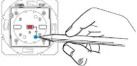 | ThecfgLEDs on the radio wall-transmitter and all receivers within radio range are extinguished. The radio command for the radio wall-transmitter has been configured. |
Table 4: Configuration of the radio wall-transmitter as a transmitter
6. Appendix
Immediately remove empty batteries and dispose of in an environmentally acceptable manner. Do not throw away batteries in household waste. The local authorities provide information about environmentally-friendly disposal. According to statutory requirements, the end consumer is obliged to return used batteries.
6.1 Technical data
Radio frequency 868.3 MHz
Radio protocol KNX radio
quicklink logic functions max. 20 transmitters/
receivers
Receiver category 2
Transmitter duty cycle < 1%
Radio transmission range (free field) 100 m
Transmission power < 10 mW
Degree of protection IP 20
Relative humidity 0 ... 65 %
(no condensation)
Ambient temperature
-5 ... +45 °C
Storage/transport temperature
-20 ... +60 °C
Assembling height
14 mm
Radio wall-transmitter flat quicklink
Rated voltage
3 V=
Battery type
1 x Lithium CR2430
Battery service life
approx. 5 years
The Declaration of Conformity can be taken from our Internet site.
6.2 Warranty
We reserve the right to realise technical and formal changes to the product in the interest of technical progress.
Our products are under guarantee within the scope of the statutory provisions.
If you have a warranty claim, please contact the point of sale.
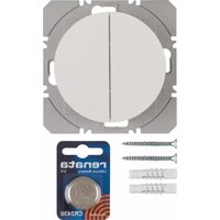
- KNX radio wall-transmitter 1gang/2gang flat quicklink
- KNX radio wall-transmitter 1gang/2gang flat solar quicklink
- Operating instructions
- Safety instructions
- Design and layout of the device
- Function
- System information
- Correct use
- Product characteristics
- Operation
- Allotting of channels to inputs of wall-transmitter
- Transmit radio command
- Transmission status LED display
- Information for electricians
- Installation
- Selecting installation location
- Assembly of the device (Figure 1)
- WARNING!
- Insertion of battery
- Changing battery
- Radio confi guration quicklink
- Wall-transmitter radio commands
- Configuration of radio wall-transmitter
- Appendix
- Technical data
- Radio wall-transmitter flat quicklink
- Warranty
Brand : HAGER
Model : 85656226
Category : Interrupteur mural radio