
SX3204 - Audio Mixer SOUNDCRAFT - Free user manual and instructions
Find the device manual for free SX3204 SOUNDCRAFT in PDF.


| Product Type | Analog Audio Mixer |
| Model | SX3204 |
| Brand | Soundcraft |
| Number of Channels | 32 Mono Inputs, 4 Stereo Returns |
| Equalization | 4-band EQ (High, Hi-mid, Lo-mid, Low) with sweepable mid |
| Main Outputs | Stereo Main L/R, Mono Sum, 4 Group Buses, 6 Aux Sends |
| Built-in Effects | Yes, 16 digital effects with dedicated send/return |
| Power Supply | AC 100-240V, 50/60Hz, internal power supply |
| Power Consumption | 60W |
| Dimensions (W x D x H) | 1040 mm x 500 mm x 180 mm |
| Weight | 22 kg (approx.) |
| Chassis Material | Steel with metal knobs |
| Main Functions | Mixing, routing, monitoring, recording, live sound reinforcement |
| Cleaning Instructions | Use a dry soft cloth; avoid solvents and water ingress |
| Safety Features | Power switch, internal fuse, ground lift switch on outputs |
| Spare Parts Availability | Repairable by authorized service centers; spare knobs, faders, power supplies available |
| General Information | Professional analog mixer for stage and studio, compatible with standard XLR and TRS cables |
| Inputs | 32 XLR/TRS combi jacks with phantom power, 4 stereo TRS returns |
| Outputs | XLR main outputs, TRS group/aux outputs, TRS monitor output |
| Phantom Power | +48V switchable per channel (in banks) |
Frequently Asked Questions - SX3204 SOUNDCRAFT
User questions about SX3204 SOUNDCRAFT
0 question about this device. Answer the ones you know or ask your own.
Ask a new question about this device
Download the instructions for your Audio Mixer in PDF format for free! Find your manual SX3204 - SOUNDCRAFT and take your electronic device back in hand. On this page are published all the documents necessary for the use of your device. SX3204 by SOUNDCRAFT.
USER MANUAL SX3204 SOUNDCRAFT
Please read this manual carefully before using your mixer for the first time.
Soundcraft by HARMAN
Soundcraft is a trading division of Harman International Industries Ltd. Information in this manual is subject to change without notice and does not represent a commitment on the part of the vendor. Soundcraft shall not be liable for any loss or damage whatsoever arising from the use of information or any error contained in this manual.
No part of this manual may be reproduced, stored in a retrieval system, or transmitted, in any form or by any means, electronic, electrical, mechanical, optical, chemical, including photocopying and recording, for any purpose without the express written permission of Soundcraft.
Harman International Industries Limited Cranborne House, Cranborne Road, POTTERS BAR, Hertfordshire, EN6 3JN, UK
Tel: +44 (0)1707 665000
Fax:+44 (0)1707 660742
http://www.soundcraft.com
IMPORTANT SAFETY INSTRUCTIONS ....4
SAFETY SYMBOL GUIDE ....5
- INTRODUCTION....6
1.1 KEY FEATURES....6
1.2 ADVICE FOR THOSE WHO PUSH THE BOUNDARIES....6
-
HOOKUP DIAGRAM....7
-
SX SERIES CONTROLS....8
3.1 OVERVIEW....8
3.2 FRONT PANEL 9
3.3 REAR PANEL....12
-
USB PLAYER....15
-
WIRING UP ....16
-
BLOCK DIAGRAM....18
-
SPECIFICATIONS....19
-
SPECIFICATIONS....20
-
WARRANTY ....21
Read these instructions.
Keep these instructions.
Heed all warnings.
Follow all instructions.
Do not use this apparatus near water.
Clean only with a dry cloth.
Do not block any ventilation openings. Install in accordance with the manufacturer's instructions.
Do not install near any heat sources such as radiators, heat registers, stoves, or other apparatus (including amplifiers) that produce heat.
Do not defeat the safety purpose of a polarised or grounding type plug. A polarised plug has two blades with one wider than the other. A grounding type plug has two blades and a third grounding prong. The wide blade or the third prong are provided for your safety. If the provided plug does not fit into your outlet, consult an electrician for replacement of the obsolete outlet.
Protect the power cord from being walked on or pinched particularly at plugs, convenience receptacles and the point where they exit from the apparatus.
Only use attachments/accessories specified by the manufacturer.

Use only with the cart, stand, tripod, bracket or table specified by the manufacturer, or sold with the apparatus. When a cart is used, use caution when moving the cart/apparatus combination to avoid injury from tip-over.
Unplug this apparatus during lightning storms or when unused for long periods of time.
Refer all servicing to qualified service personnel. Servicing is required when the apparatus has been damaged in any way, such as power-supply cord or plug is damaged, liquid has been spilled or objects fallen into the apparatus, the apparatus has been exposed to rain or moisture, does not operate normally, or has been dropped.

NOTE: It is recommended that all maintenance and service on the product should be carried out by Soundcraft or its authorised agents. Soundcraft cannot accept any liability whatsoever for any loss or damage caused by service, maintenance or repair by unauthorised personnel.

WARNING: To reduce the risk of fire or electric shock, do not expose this apparatus to rain or moisture. Do not expose the apparatus to dripping or splashing and do not place objects filled with liquids, such as vases, on the apparatus. No naked flame sources, such as lighted candles, should be placed on the apparatus.
Ventilation should not be impeded by covering the ventilation openings with items such as newspapers, table cloths, curtains etc.
THIS APPARATUS MUST BE EARTHED. Under no circumstances should the safety earth be disconnected from the mains lead.
The mains supply disconnect device is the mains plug. It must remain accessible so as to be readily operable when the apparatus is in use.
If any part of the mains cord set is damaged, the complete cord set should be replaced. The following information is for reference only.
The wires in the mains lead are coloured in accordance with the following code:
Earth (Ground): Green and Yellow (US - Green/Yellow)
Neutral: Blue (US - White)
Live (Hot): Brown (US - Black)
IMPORTANT SAFETY INSTRUCTIONS
As the colours of the wires in the mains lead may not correspond with the coloured markings identifying the terminals in your plug, proceed as follows:
- The wire which is coloured Green and Yellow must be connected to the terminal in the plug which is marked with the letter E or by the earth symbol.
- The wire which is coloured Blue must be connected to the terminal in the plug which is marked with the letter N.
- The wire which is coloured Brown must be connected to the terminal in the plug which is marked with the letter L.
- Ensure that these colour codes are followed carefully in the event of the plug being changed.
This unit is capable of operating over a range of mains voltages as marked on the rear panel.
FOR YOUR OWN SAFETY AND TO AVOID INVALIDATION OF THE WARRANTY PLEASE READ THIS SECTION CAREFULLY.
SAFETY SYMBOL GUIDE
For your own safety and to avoid invalidation of the warranty all text marked with these symbols should be read carefully.
WARNINGS

The lightning flash with arrowhead symbol, is intended to alert the user to the presence of un-insulated “dangerous voltage” within the product’s enclosure that may be of sufficient magnitude to constitute a risk of electric shock to persons.
CAUTIONS

The exclamation point within an equilateral triangle is intended to alert the user to the presence of important operating and maintenance (servicing) instructions in the literature accompanying the appliance.
NOTES

Contain important information and useful tips on the operation of your equipment.
HEADPHONES SAFETY WARNING

Contain important information and useful tips on headphone outputs and monitoring levels.
1. INTRODUCTION
Thank you for purchasing the SX Series mixing console. SX2404/SX3204 are available for 24/32 channels. Your SX Series is a remarkable compact mixer that doesn't find many equals in the market today, with 18/26 MIC and 6 Stereo Line-level inputs for serious live performances. There is a 2-band fixed and 2-band sweep EQ on mono channels, 4-band fixed EQ on stereo channels. It can be used for large gigs and fixed PA installations.
Enjoy your SX Series and make sure to read this manual carefully before operation!

NOTE: The packaging, in which your console arrived, forms part of the product and must be retained for future use.
1.1 KEY FEATURES
The SX series includes many unique technological and operational qualities which include:
• 18/26 MIC inputs with gold plated XLR and balanced LINE inputs
- 6 Stereo input channels with balanced TRS jacks
- Ultra-low noise discrete MIC preamps with +48 V Phantom Power
- Extremely high headroom offering more dynamic range
• Each input channel with Mute, SOLO function, overload LEDs & low cut filters
- MIC channel with LOW CUT filters and PHASE
- 6 AUX sends per channel, AUX1-2/AUX3-4/AUX5-6 with PRE/POST faders switchable
• 2-bands fixed and 2-bands sweep EQ on mono channels
• 4-band fixed EQ on stereo channels
- SUB1-2,SUB3-4,MAIN L-R,CENTER signal assignment switch
• 100mm high precision faders
- Channel inserts and direct outputs on each mono channel plus main mix insert for flexible connection of outboard equipment
• MATRIX A & B for (SUB1-SUB2)(SUB3-SUB4)(L-R)(CENTER)
• Control room/phones matrix
- 2-TRACK IN assignable to main mix, control room/headphone outputs
• Fully assignable Talkback sections
- With USB port, record from SUB1-2 or MAIN OUT and play to CH23-24 MAIN BUS
1.2 ADVICE FOR THOSE WHO PUSH THE BOUNDARIES

Although your new console will not output any sound until you feed it signals, it has the capability to produce sounds which, when monitored through an amplifier or headphones, can damage hearing over time.
Please take care when working with your audio — if you are manipulating controls which you don't understand (which we all do when we are learning), make sure your monitors are turned down.
Most importantly — don't be afraid to experiment to find out how each parameter affects the sound — this will extend your creativity and help you to get the best from your mixer and the most respect from your artists and audience.
![graph TD A["HEADPHONE"] --> B["STAGEMONITOR"] B --> C["CDPLAYER"] C --> D["D/IBOX"] D --> E["GUITAR"] E --> F["BASS"] F --> G["DRUMMACHINE"] G --> H["WIRELESS MICROPHONE2"] G --> I["WIRELESS MICROPHONE 1"] G --> J["MIC 4"] G --> K["MIC 3 MIC2"] G --> L["MIC 1"] M["ACTIVESPEAKERS"] --> N["ACTIVESPEAK…](/content/2026/06/1359297/images/9660e6b36d04f73d23f4a572f7085443fb6737b1a4078c82f04514070929c371.jpg)
3. SX SERIES CONTROLS
3.1 OVERVIEW



3. SX SERIES CONTROLS
3.2 FRONT PANEL

1- PHASE SWITCH(EXCEPT FOR CH21/22, 23/24)
This switch allows the user to invert by 180 the signal. This switch is very useful in a lot of circumstances, in particular when several microphones are very close (e.g. Drum kit, brasses, chorus, etc.) And the sound engineers notices interferences between microphones that can not be solved moving the microphones.
2- LOW-CUT BUTTON
By pressing this button, you will activate a 75Hz low frequency filter with a slope of 18 dB per octave. You can use this facility to reduce the hum noise infected by the mains power supply, or the stage rumble while using a microphone.
3- GAIN
The GAIN control is applied in the mono MIC and stereo input channels. It provides with 2 different indications: One is for the MIC and the other for LINE levels. When you use a microphone, you shall read the MIC ring (0\~50 for mono MIC input, 0\~40 for stereo channels); when you use a line level instrument, you shall read the LINE ring (+15\~-35 dB for mono MIC input, +20\~-20 dB for stereo channels). For optimum operation, you shall set this control in a way that the PEAK LED(15) blinks only occasionally in order to avoid distortion on the input channel.
4- LEVEL SET LED
This LED will help you to detect the input level immediately. In this case, the research of the fault will become much faster!
5- LINE/MP3 BUTTON(CH 21/22)
By pressing this button, it will switch to the MP3 mode, the MP3 signal can be sent to this channel. By releasing this button, the LINE IN inputs signal will send to the input channel.
6- LINE/USB BUTTON(CH 23/24)
By pressing this button, it will switch to the USB mode, then the USB signal can be sent to this channel; by releasing this button, the LINE IN inputs signal will send to the input channels.
EQUALISER
There are 2-band fixed and 2-band sweep EQ on mono channels: HI, MID-HI, MID-LOW and LOW. There are 4-band fixed EQ on the stereo channel HI, HI-MID, MID-LOW and LOW band.
7-HIGH
If you turn this control up, you will boost all the frequencies above 12 kHz (shelving filter). You will add transparency to vocals and guitar and also make cymbals crispier. Turn the control down to cut all frequencies above 12 kHz. In such way, you can reduce sibilance of human voice or reduce the hiss of a Tape player.
8- MID-HI(0.5-12K) & MID-LOW(80-2K)
This is a peaking filter and it will boost/cut frequencies from 100 Hz to 8 kHz depending on the position of the MID freq control. This control will affect especially upper male and lower female vocal ranges and also the harmonics of most musical instruments.
9-HI-MID
This control gives you up to 15 dB boost or cut at 3 kHz. It is useful for controlling voice. It can accurately polish your performance via adjusting this knob.

3. SX SERIES CONTROLS

10- MID-LOW
This control gives you up to 15 dB boost or cut at 500 Hz.
11-LOW
If you turn this control up, you will boost all frequencies below 80 Hz. You will give more punch to bass drum and bass guitar and make the vocalist more "macho". Turn it down, you will cut all the frequencies below 80 Hz. In this way, you can avoid low frequency vibrations and resonance thus preserving the life of your woofers.
12- EQ SWITCH
This switch allows the user to use the EQ Section in signal path. Of course it can be used to make A/B comparisons between equalized signal and not equalized signal. It also can be used to apply equalization at a certain point of the show, excluding it when it's not necessary.
These six controls are used to adjust the level of the respective signal sent to AUX bus, AUX-1,AUX2, AUX3,AUX4,AUX5,AUX6 can be switched to PRE/POST-FADER via the PRE/POST button, so, generally, they can be used for monitor application and effects & sound processors input. In this typical compact unit, excluding sending out the signal directly to the external effect or processor equipment, AUX SEND 5&6 can also be assigned to the internal onboard effect module.
14-PAN CONTROL
Abbreviation of PANORAMA control for mono channels, or the stereo channels, always says, BALANCE control. Keep this control in center position, then the signal will be positioned in the middle of stage.
15-PEAK LED
Inside your SX series, the audio signal is monitored in several different stages and then sent to the PEAK LED. When the LED is red illuminated, it warns you that you are reaching signal saturation and possible distortion, then you should reduce the input level for avoiding distortion.
16-MUTE BUTTON & LED
Each channel is equipped with a MUTE button. Pressing this button is equal to turning the fader down, which can mute the corresponding channel output except for the channel INSERT send and SOLO (in PFL mode). And the MUTE LED will illuminate.
17-FADER
This fader will adjust the overall level of this channel and set the amount of signal send to the main output.
18-ASSIGNMENT Controls
Each channel provides four push-buttons: SUB1-2, SUB3-4, MAIN L-R, CENTER and SOLO. Pressing the SOLO button, the corresponding SOLO LED will illuminate and the SOLO signal will replace other signals send to the Headphone/Control Room and Meters. Usually use the SOLO function in live work to preview channels before they are let into the mix.
It is useful to set an instrument's input level and EQ, and you can also solo any channel that you want to. The SOLO switch never affects any mix other than the Control Room. The other three buttons can be considered as signal assignment switches.
Pressing the SUB1-2 will assign the channel signal to Subgroup1/2, you can depend on the PAN switch to adjust the amount of channel signal sent to the SUB1 versus SUB2, when turns the PAN to completely left, then the signal can be only controlled by Subgroup1 and vice versa. In the same way, pressing the SUB3-4 or MAIN L/R will assign the channel signal to Subgroup 3/4 or MAIN MIX L/R, and will also be affected by PAN.
3. SX SERIES CONTROLS

19- MASTER AUX SENDS CONTROLS
These six controls are used to determine the master AUX SEND levels, which can be varied from -∞ to +15 dB. When the external effect units which have no input gain control were connected to mixer, you can get a further +15 dB gain available from these AUX Send outputs.
20- SOLO Button
The function of these SOLO buttons are the same as the channel SOLO button, they can also be affected by the SOLO MODE switch. Press the SOLO button, the corresponding AUX send will be routed to the Control Room/Phones outputs and Meters display.
21- MASTER STEREO AUX RETURNS CONTROLS
These four controls set the level of effects that received from the stereo AUX RETURN connectors, which can be varied from -∞ to +15 dB. They are used to provide the further gain for low level effects.
22- TO AUX SEND1/2
The both rotary knobs assign the AUX RETURN signals to their respective AUX SEND outputs: The "TO AUX SEND1" assign the signal from AUX RETURN1 to AUX SEND1 bus, and "TO AUX SEND2" assign the signal from AUX RETURN2 to AUX SEND2 bus. The adjustable range goes from -∞ to +15 dB.
23- SUB1-2/SUB3-4/MAIN L-R/CENTER BUTTONS
These two groups of buttons are configured for AUX RETURN3/4, they can be regarded as the signal assignment switches. For example, When engaging the SUB1-2, the stereo signal from AUX RETURN3 will be assigned to Sub-group1/2; In the same way, SUB3-4 for Subgroup3/4, MAIN L-R for MAIN L-R buses.
24- MATRIX A&B
These controls will allow the sound engineer to address SOURCES SIGNAL to SUB1, SUB2, SUB3, SUB4, MAIN L, MAIN R, CENTER.
By rotate the knobs, you can adjust the stereo signals level of 2TK input and engaging the switch allows you to combine the 2-Track output with the Main Mix. In other words, feeds the 2-Track In signals into Main L/R output.
26- SUBGROUPS ASSIGN TO MAIN MIX
Through these switches, you can operate the subgroup faders as a master control for assigning the subgroups to MAIN MIX.
27- POWER LED
The LED indicates when the power is ON.
28- LED METER
The stereo 16-segment LED Meter will indicate the signal level send to the Control Room and Phones outputs.
29- SOLO ACTIVE
This LED indicates that the one or more SOLO button have been activated. When this LED is on, the METERS indicates the level of the signal of the selected channel or mixer section in AFL mode.
3. SX SERIES CONTROLS
30- SOLO MODE BUTTON
This button provides two modes: up for PFL (Pre-Fader-Listen) mode, down for AFL (After-Fader-Listen) mode. Engage the button, the soloed signal will output after the Level control, otherwise, release the button will output the soloed signal before the Level control.

NOTE: The SOLO function can never affect the mix at main recording output, and also can't be affected by channel's MUTE switch.
31- PHONES/CTRL ROOM CONTROL
Rotate this knob to adjust the stereo level of CTRL ROOM & PHONES outputs separately, which can be varied from - to MAX.
32- CONTROL ROOM SOURCE
You can choose to monitor any combination of MAIN L-R, SUB1-2, SUB 3-4 and CENTER via these Matrix switches. Engaging these switches, the stereo signals will be delivered to the Phones, Control Room and Meters display.

NOTE: When any SOLO switch was engaged, the SOLO signal will replace other signals, and also be sent to the Control Room, Phones and Meters.
33- SUBGROUPS FADER
These faders are used to control the levels of the signal send to the SUB-GROUPS OUT, the adjustable range goes from - to +10 dB. Any channel that is assigned to the subgroups, not muted and not turned down will be assigned to the SUB OUTS.
This fader sets the amount of signal send either to the Main Mix Output or to the Tape Output.
35- TALKBACK LEVEL
This is the main level control for the talkback section.
36- TALKBACK SWITCH
This switch activates and sends the talkback signal to its selected outputs.
37- TALKBACK SIGNAL ASSIGNMENT SWITCHES
AUX1-2,AUX3-4,AUX5-6 switches will allow the sound engineer to address the SOURCES signal to Auxiliaries. In this way you can send, e.g.,The Talkback signal to all stage monitors to communicate directly with performers while audience will hear
SUB1-2, SUB3-4, MAIN L-R, CENTER switches allow the sound engineer to assign the talkback signal to the audio path he wants to. The odd/even numbered switches are used to send the signal to subgroups (then you can send their signal to L/R outs) while L/R switch sends the signal directly to Main Mix.
![graph TD A["+10"] --> B["QIN"] B --> C["SJK12"] B --> D["SJK14"] C --> E["MOS L18"] D --> F["CB/TEN"] E --> G["ALU11 2"] F --> H["ALU13 4"] G --> I["ALU15 5"] H --> J["35"] I --> K["36"] J --> L["37"]](/content/2026/06/1359297/images/9ce6dec0de0fda71f61dfa30a255d36c63e391ceb9bbbb351059f03014188b71.jpg)
3.3 REAR PANEL
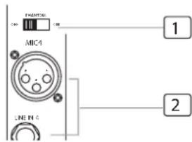
1- +48 V PHANTOM POWER SWITCH
It is available only to the XLR MIC sockets. Never plug in a microphone when phantom power is already on. Before turning phantom power on, make sure that all faders are totally down. In this way, you will protect your stage monitors and main loudspeakers.
3. SX SERIES CONTROLS
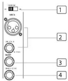

NOTE: this phantom power switch will control the adjacent four MIC channels, such as from CH1-CH4.
2- MONO MIC/LINE CHANNELS
Your SX series is equipped with 18/26 low-noise microphone pre-amplifier with optional phantom power, 50 dB of Gain and over 115 dB of S/N ratio. You can connect almost any type of microphone. Dynamic microphones do not need phantom power. Use phantom power only with condenser microphones but make sure that the phantom power button is disengaged before connecting the microphone. Phantom power may damage your dynamic microphones, so make sure to read the MIC instructions manual before engaging phantom power. Use switch (1) to activate/deactivate phantom power. These channels are also equipped with 1/4" TRS balanced/unbalanced LINE-IN plugs to connect line-level instruments such as keyboards, drum machines and effect devices.

3- MONO CHANNEL INSERT
This is where you connect external sound processors such as compressor-limiter, equalizers, etc.. MONO channel inserts are available for mono channels 1-12 for SX2404 (mono channels 1-12 and 25-32 for SX3204)
4- DIRECT OUTS
Each Mono MIC/LINE Channel is equipped with the 1/4" phone jack for directing output. These jacks are used to send the signal from the channel path to external device for recording function etc..
5- STEREO INPUTS
These are channels 13 to 24. They are organised in stereo pair & provided with XLR sockets and 1/4" TRS phone jacks. If you connect only the left jack, the input will operate in mono mode, that is the mono signal will appear on both input channels. You can use these inputs with a stereo keyboard, drum machine, etc.
6-2-TRACK (TAPE IN)
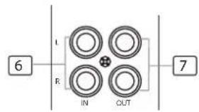
Use the tape input if you wish to listen to your mix from a Tape Recorder or DAT.
7-2-TRACK (TAPE OUT)
These RCA jacks will route the main mix into a tape recorder.
8-USB PORT
This USB port is used to connect the unit to PC with a transmission line. When it is in RECORD mode, it can connect with the SUB1-2 or MAIN MIX output when in the PLAYBACK mode, it can connect with CH23/24 or MAIN MIX.

You can select SUB1/2 or MAIN MIX track to input the record signal to PC.
10- USB PLAYBACK SWITCH
You can select Ch23/24 or MAIN MIX track to output audio signal from PC.
11- AUX RETURNS JACKS
Use these stereo 1/4" phone jacks to return the stereo signal of an effect unit to the Main Mix. Alternatively you can also use them as an extra auxiliary input via using the AUX RETURN level control as volume control. The signal will be sent directly to MAIN MIX control.
3. SX SERIES CONTROLS

12- AUX SENDS
These 1/4" phone jacks are sued to send out the signal from the AUX Bus to external devices such as effect units and/or stage monitors.
13- SUBGROUPS OUT JACKS
These 1/4" phone jacks are used to connect the inputs of deck or secondary in a complicated PA live sound system. You will find it is the best tool when you operate the SUBGROUPS OUT.
14- SUBGROUPS INSERTS
These 1/4" phone jacks are insert points. They are used to connect processors, such as compressor, limiter, EQ, etc. When insert external processor into these jacks, the subgroup stereo signal will be taken out, then returned to before subgroups fader. Of course, these used jacks must be stereo (Tip Send/Ring Return)
15- MAIN INSERT
These two 1/4" phone jacks are stereo insert points and used to connect processors such as compressors, equalisers etc. When insert an external processor into the jack, the Main stereo signal will be taken out after the EQ and returned into the MAIN MIX output before the MAIN MIX fader.
16- MAIN MIX OUTPUT
These stereo outputs are supplied with both the XLR and 1/4" phone jacks and it is controlled by the Main Mix level.
17- CTRL OUT JACKS
These 1/4" phone jacks will be used to send the Control Room signal to the studio monitor speakers or a second set of PA.
18- PHONES JACKS
This jack will be used to send the signal to a pair of headphone or to powered studio monitors.
19- TALKBACK INPUT
This input is for a talkback microphone, that will be managed by TALKBACK Section.
20- POWER SWITCH
This switch is used to turn the main power on and off.
21- AC INLET with FUSE HOLDER.
Use it to connect your SX series to the main AC with the supplied AC cord. Please check voltage available in your country and how the voltage for your SX series is configured before attempting to connect to main AC.
22-CENTER JACK
This 1/4" phone jack is used to send out the signal from CENTER Bus to Main MIX, and it is controlled by CENTER Fader.
23- MATRIX JACKS
These two balanced TRS jacks are for MATRIX A & B output.
4. USB PLAYER
The file system of USB memory for USB players is FAT16 and FAT32, and these players can only decode Mp3. It has 7 rank subordinate folders at most.
![graph TD A["USB PLAYER"] --> B["TAC-MP3-T"] B --> C["Power (Flush & Hold)"] C --> D["USB"] D --> E["2134"] E --> F["8"] B --> G["567"]](/content/2026/06/1359297/images/a2ee1ce1022b9ef3145cbe8b0e952ff9e7feac0399aab31a4215c0f453a1f964.jpg)
1- USB port: For connecting with USB memory equipment.
2- PRE: In pause state, press this key, it will go to previous track and keep in pause state. In play state, press this key, it will go to the previous track and start playing.
3- NEXT: In pause state, press this key, it will go to next track and keep in pause state. In play state, press this key, it will go to the next track and start playing.
4- RPT: Press this key, the player will change between the following four modes:
REP ALL means to repeat all tracks in the memory, mark on the screen is
REP1 means to repeat one track, the mark on the screen is
Play in order means to play the tracks according to the order, the mark on the screen is blank.
Random play means to play the tracks at random, the mark on the screen is A.
5- PLAY/PAUSE: In play state, press PLAY/PAUSE key to pause the player. In pause state, press PLAY/PAUSE key to start playing.
6- STOP: In play state, press this key to stop playing and all the songs in USB memory will appear on the display; In stop state, press STOP/ PRE/ NEXT keys again to go to first song and the player will keep in pause state, then press PLAY/PAUSE key to play the song.
7- POWER (Push and Hold): When the unit is off, press this key and hold for about 2 or 3 seconds to turn on the power supply of player. Repeat the above operation, you can turn off the power supply of the player.
8- DISPLAY: All MP3 player information are monitored via this sexy & magic display.

NOTE: basic interface instruction

When the player isn't connected to a USB memory equipment, the interface is as left shown:

When the player is searching for USB tracks, the interface is as left shown:

When the player is in pause state, the interface is as left shown:
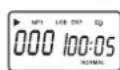
When the player is in use, the interface is as left shown:
5. WIRING UP
OK, you have got to this point and you are now in the position to successfully operate your SX series. However, we advise you to read the following section carefully to be the real master of your own mix.
Not paying enough attention to the input signal level, the routing of the signal and the assignment of the signal will result in unwanted distortion, a corrupted signal or no sound at all. So you should follow this procedure for every single channel:
- Turn down all Input and output gain controls.
- Connect phantom powered microphones before switching on the +48 Volt phantom power switch.
- Set the output level of your SX series mixer or the connected power amplifier at no more than 75%.
- Now, set the CONTROL ROOM/PHONES level at no more than 50%. In this way, you will be able to hear later what you are doing connecting a pair of headphones or a pair of powered studio monitor speakers.
- Position EQ controls on middle position.
- Position panoramic (PAN/BAL) control on center position.
- With a pair of headphone or studio monitor speakers are connected, apply a Line Level input signal so that the PEAK LED does not light up.
- Increase the input gain properly for maintaining the good headroom and ideal dynamic range.
- Depending on the actual application, turn slowly the input and output level controls for obtaining the maximum gain before distortion.
- Now repeat the same sequence for all input channels. The main LED meter could move up into the red section. In this case you can adjust the overall output level through the main mix control.
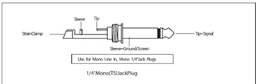
Audio Connections
You can connect unbalanced equipment to balanced inputs and outputs. Simply follow these schematics.



![graph TD A["MP1 CH2"] --> B["USB BOARD"] C["MP1A MCH"] --> D["USB BOARD"] E["STEREO AUX RTN"] --> F["DHP BOARD"] G["LEMON"] --> H["USB BOARD"] I["LEMON"] --> J["USB BOARD"] K["LEMON"] --> L["USB BOARD"] M["LEMON"] --> N["USB BOARD"] O["LEMON"] --> P["USB BOARD"] Q["LEMON"] --> R["USB BOARD"] S["LEMO…](/content/2026/06/1359297/images/fde47790a4e105a6019e3730cedf16df8f92e32361a56474816e142ded1d7db8.jpg)
7. SPECIFICATIONS
Input
| Input impedance MIC 2 k ohm Balanced |
| Line 10kohm Balanced |
| Input gain MIC continuously variable from 0dB to +50dB |
| Line-Mono Channel continuously variable from -15dBto+35dB |
| Line-Stereo Channel continuously variable from -20dB to+20dB |
| Maximum input level MIC +22dBu |
| Line(Mono Channel)+22dBu |
| Line(Stereo Channel)+22dBu |
| Insert send impedance 120 ohm Unbalanced |
| Insert send level/Max -10dBu/+22dBu |
| Insert return impedance 10 k ohm Unbalanced |
| Insert return level/Max. -10dBu/+22dBu |
| CMR at 1 kHz Line(20Hz-20kHz) >60dB |
| Frequency Response MIC to Mix 20Hz-20kHz +/-3dB |
| Signal/Noise Ratio(20Hz-20kHz) MIC EIN ref.150ohms - 117dBu |
System Noise(20Hz-20kHz)
| Summing noise -90dBu(24channels routed with faders down) | |
| Line to Mix Noise -86dBu(24 channels routed at 0dB, pan center) | |
| Distortion at 1 kHz MIC to insert(+30dB unity gain, +20dBu output)<0.009% | |
| Mix to Mix(+30dB unity gain, +20dBu output)Typ 0.03% | |
| Crosstalk at 1 kHz | Channel to channel >-80dB |
| Mix to Mix >-80dB | |
| Channel to Mix >-80dB | |
| Fader Attenuation | >100dB |
Output(nominal signal level mic-50dBu to 0dBu -Line 0dBu)
| Output impedance | All line outputs 120 ohm Balanced |
| Insert send impedance 120 ohm Unbalanced | |
| Insert send level/Max +22dBu | |
| Insert return impedance 10 k ohm Unbalanced | |
| Insert return level/Max | +22dBu |
| Maximum output level master outputs on XLR | +28dBu |
| All outputs on 1/4" jacks | +22dBu |
| Headphones | +22dBu/600 ohm |
Main Mix Section
| HI-shelving | +/-15dB @12 kHz |
| MID HI-bell(STEREO) | +/-12dB @3 kHz |
| MID-bell(MONO) | +/-12dB frequency range 100Hz - 8KHz |
| MID LOW-bell(STEREO) +/-12dB @ 500hz | |
| Bass-shelving | +/-15dB @ 80Hz |
| Hi Pass Filter Slope | -18dB/Oct. @75Hz |
Power Supply
| Power Supply | 100-240V~50/60Hz |
7. SPECIFICATIONS
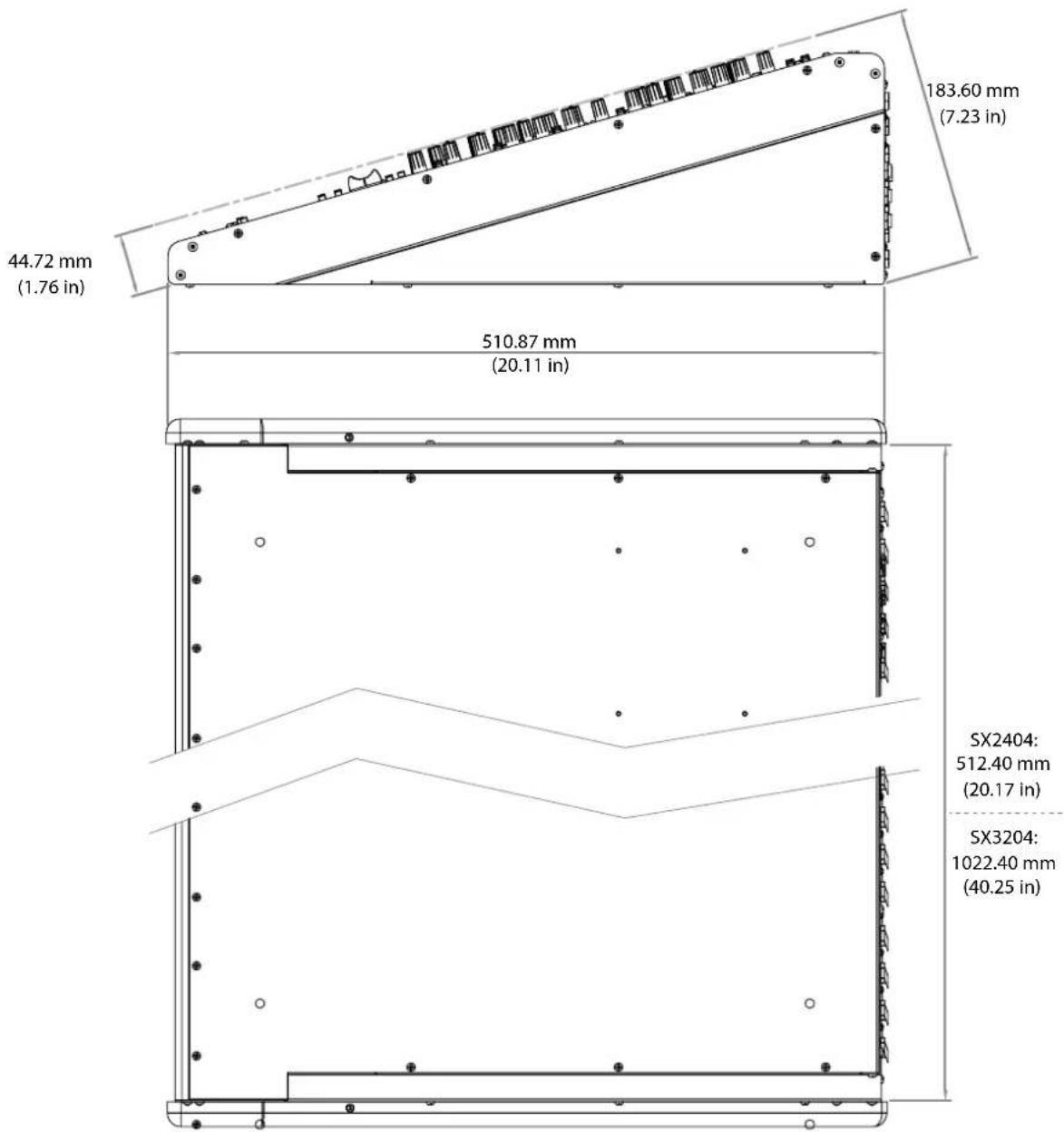
Weights and Dimensions
SX2404 14.1Kg/31.1Lbs
SX3204 18.5Kg/40.8Lbs
8. WARRANTY
- Soundcraft is a trading division of Harman International Industries Ltd. End User means the person who first puts the equipment into regular operation. Dealer means the person other than Soundcraft (if any) from whom the End User purchased the Equipment, provided such a person is authorised for this purpose by Soundcraft or its accredited Distributor. Equipment means the equipment supplied with this manual.
- If within the period of twelve months from the date of delivery of the Equipment to the End User it shall prove defective by reason only of faulty materials and/or workmanship to such an extent that the effectiveness and/or usability thereof is materially affected the Equipment or the defective component should be returned to the Dealer or to Soundcraft and subject to the following conditions the Dealer or Soundcraft will repair or replace the defective components. Any components replaced will become the property of Soundcraft.
- Any Equipment or component returned will be at the risk of the End User whilst in transit (both to and from the Dealer or Soundcraft) and postage must be prepaid.
- This warranty shall only be available if:
a). The Equipment has been properly installed in accordance with instructions contained in Soundcraft's manual.
b). The End User has notified Soundcraft or the Dealer within 14 days of the defect appearing.
c). No persons other than authorised representatives of Soundcraft or the Dealer have effected any replacement of parts maintenance adjustments or repairs to the Equipment.
d). The End User has used the Equipment only for such purposes as Soundcraft recommends, with only such operating supplies as meet Soundcraft's specifications and otherwise in all respects in accordance Soundcraft's recommendations. - Defects arising as a result of the following are not covered by this Warranty: faulty or negligent handling, chemical or electro-chemical or electrical influences, accidental damage, Acts of God, neglect, deficiency in electrical power, air-conditioning or humidity control.
- The benefit of this Warranty may not be assigned by the End User.
- End Users who are consumers should note their rights under this Warranty are in addition to and do not affect any other rights to which they may be entitled against the seller of the Equipment
Soundcraft® by HARMAN
Soundcraft
Harman International Industries Ltd
Cranborne House
Cranborne Road
Potters Bar
Herts. EN6 3JN
United Kingdom
+44 (0)1707 665000
www.soundcraft.com
- PLEASE READ THIS MANUAL CAREFULLY BEFORE USING YOUR MIXER FOR THE FIRST TIME
- IMPORTANT SAFETY INSTRUCTIONS
- SAFETY SYMBOL GUIDE
- WARNINGS
- CAUTIONS
- NOTES
- HEADPHONES SAFETY WARNING
- INTRODUCTION
- 1.1 KEY FEATURES
- 1.2 ADVICE FOR THOSE WHO PUSH THE BOUNDARIES
- SX SERIES CONTROLS
- 3.2 FRONT PANEL
- PHASE SWITCH(EXCEPT FOR CH21/22, 23/24)
- LOW-CUT BUTTON
- GAIN
- LEVEL SET LED
- LINE/MP3 BUTTON(CH 21/22)
- LINE/USB BUTTON(CH 23/24)
- EQUALISER
- 7-HIGH
- MID-HI(0.5-12K) & MID-LOW(80-2K)
- 9-HI-MID
- MID-LOW
- 11-LOW
- EQ SWITCH
- 14-PAN CONTROL
- 15-PEAK LED
- 16-MUTE BUTTON & LED
- 17-FADER
- 18-ASSIGNMENT CONTROLS
- MASTER AUX SENDS CONTROLS
- SOLO BUTTON
- MASTER STEREO AUX RETURNS CONTROLS
- TO AUX SEND1/2
- SUB1-2/SUB3-4/MAIN L-R/CENTER BUTTONS
- MATRIX A&B
- SUBGROUPS ASSIGN TO MAIN MIX
- POWER LED
- LED METER
- SOLO ACTIVE
- SOLO MODE BUTTON
- PHONES/CTRL ROOM CONTROL
- CONTROL ROOM SOURCE
- SUBGROUPS FADER
- TALKBACK LEVEL
- TALKBACK SWITCH
- TALKBACK SIGNAL ASSIGNMENT SWITCHES
- 3.3 REAR PANEL
- 48 V PHANTOM POWER SWITCH
- MONO MIC/LINE CHANNELS
- MONO CHANNEL INSERT
- DIRECT OUTS
- STEREO INPUTS
- 6-2-TRACK (TAPE IN)
- 7-2-TRACK (TAPE OUT)
- 8-USB PORT
- USB PLAYBACK SWITCH
- AUX RETURNS JACKS
- AUX SENDS
- SUBGROUPS OUT JACKS
- SUBGROUPS INSERTS
- MAIN INSERT
- MAIN MIX OUTPUT
- CTRL OUT JACKS
- PHONES JACKS
- TALKBACK INPUT
- POWER SWITCH
- AC INLET WITH FUSE HOLDER
- 22-CENTER JACK
- MATRIX JACKS
- USB PLAYER
- NOTE: BASIC INTERFACE INSTRUCTION
- WIRING UP
- AUDIO CONNECTIONS
- SPECIFICATIONS
- WARRANTY
- SOUNDCRAFT® BY HARMAN
Brand : SOUNDCRAFT
Model : SX3204
Category : Audio Mixer