
LC4H - Measuring equipment PANASONIC - Free user manual and instructions
Find the device manual for free LC4H PANASONIC in PDF.


| Product Type | Digital Counter/Timer |
| Model | LC4H |
| Brand | Panasonic |
| Display | 4-digit LED, red |
| Digit Height | 7.6 mm |
| Power Supply | 100–240 VAC, 50/60 Hz or 12–24 VDC |
| Power Consumption | Approx. 4.5 VA (AC) / 2.5 W (DC) |
| Operating Temperature | -10°C to +55°C |
| Storage Temperature | -25°C to +70°C |
| Dimensions (W×H×D) | 48 mm × 48 mm × 83 mm |
| Panel Cutout | 45 mm × 45 mm |
| Weight | Approx. 100 g |
| Input Types | NPN/PNP open collector, voltage pulse |
| Counting Speed | 30 Hz (max) |
| Operating Modes | Up/Down counting, timer, frequency measurement |
| Preset Output | Relay (1c) or transistor (NPN/PNP) |
| Protection Class | IP66 (front panel) |
| Maintenance | Wipe with soft dry cloth; do not use solvents |
| Safety Standards | UL, CE, RoHS compliant |
| Spare Parts Availability | Replacement units and accessories available through Panasonic distributors |
Frequently Asked Questions - LC4H PANASONIC
User questions about LC4H PANASONIC
0 question about this device. Answer the ones you know or ask your own.
Ask a new question about this device
Download the instructions for your Measuring equipment in PDF format for free! Find your manual LC4H - PANASONIC and take your electronic device back in hand. On this page are published all the documents necessary for the use of your device. LC4H by PANASONIC.
USER MANUAL LC4H PANASONIC
R6/T6 systems (6-digit display)

Pin type / Screw terminal type
FEATURES
1. Bright and Easy-to-Read Display
A brand new bright 2-color backlight LCD display. The easy-to-read screen in any location makes checking and setting procedures a cinch.
2. Simple Operation
Seesaw buttons make operating the unit even easier than before.
3. Short Body of only 64.5 mm (2.539 inches)
inch (screw type) or 70.1 mm (2.760 inches) (pin type)
With a short body, it easily installs in even narrow control panels.
4. Conforms to IP66's Weather
Resistant Standards
The water-proof panel keeps out water and dirt for reliable operation even in poor environments.
5. Screw terminal and Pin Type are Both Standard Options
The two terminal types are standard options to support either front panel installation or embedded installation.
6. Changeable Panel Cover
Also offers a black panel cover to meet your design considerations.
7. 4-digit or 6-digit display
Two sizes of displays are offered for you to choose the one that suits your needs.
8. Conforms With EMC and Low Voltage Directives
Conforms with EMC directives
(EN50081-2/EN50082-2) and low-voltage directives (VDE0435/Part 2021) for CE certification vital for use in Europe.
PRODUCT TYPES
| Digit | Count speed | Output mode | Output | Operation voltage | Power down insurance | Terminal | Part No. |
| 4 | 30 Hz (cps)/5 KHz (Kcps) switchable | Maintain output/hold countMaintain output/over count IMaintain output/over count IIOne shot/over countOne shot/recount IOne shot/recount IIOne shot/hold count(7 modes) | Relay(1c) | 100-240 V AC | Available | 8 pin | LC4H8-R4-AC240V |
| 11 pin | LC4H-R4-AC240V | ||||||
| 24 V AC / 24 V DC | Screw | LC4H-R4-AC240VS | |||||
| 8 pin | LC4H8-R4-AC24V | ||||||
| 11 pin | LC4H-R4-AC24V | ||||||
| 12-24 V DC | Screw | LC4H-R4-AC24VS | |||||
| 8 pin | LC4H8-R4-DC24V | ||||||
| 11 pin | LC4H-R4-DC24V | ||||||
| Transistor(1a) | 100-240 V AC | Screw | LC4H-R4-DC24VS | ||||
| 24 V AC / 24 V DC | 8 pin | LC4H8-T4-AC240V | |||||
| 11 pin | LC4H-T4-AC240V | ||||||
| 12-24 V DC | Screw | LC4H-T4-AC240VS | |||||
| 8 pin | LC4H8-T4-AC24V | ||||||
| 11 pin | LC4H-T4-AC24V | ||||||
| Screw | LC4H-T4-AC24VS | ||||||
| 8 pin | LC4H8-T4-DC24V | ||||||
| 11 pin | LC4H-T4-DC24V | ||||||
| Relay(1c) | 100-240 V AC | Screw | LC4H-T4-DC24VS | ||||
| 8 pin | LC4H8-R6-AC240V | ||||||
| 11 pin | LC4H-R6-AC240V | ||||||
| 24 V AC / 24 V DC | Screw | LC4H-R6-AC240VS | |||||
| 8 pin | LC4H8-R6-AC24V | ||||||
| 11 pin | LC4H-R6-AC24V | ||||||
| Screw | LC4H-R6-AC24VS | ||||||
| 12-24 V DC | 8 pin | LC4H8-R6-DC24V | |||||
| 11 pin | LC4H-R6-DC24V | ||||||
| Transistor(1a) | 100-240 V AC | Screw | LC4H-R6-DC24VS | ||||
| 8 pin | LC4H8-T6-AC240V | ||||||
| 11 pin | LC4H-T6-AC240V | ||||||
| Screw | LC4H-T6-AC240VS | ||||||
| 24 V AC / 24 V DC | 8 pin | LC4H8-T6-AC24V | |||||
| 11 pin | LC4H-T6-AC24V | ||||||
| Screw | LC4H-T6-AC24VS | ||||||
| 12-24 V DC | 8 pin | LC4H8-T6-DC24V | |||||
| 11 pin | LC4H-T6-DC24V | ||||||
| Screw | LC4H-T6-DC24VS |
* A rubber gasket (ATC18002) and a mounting frame (AT8-DA4) are included.
PART NAMES


SPECIFICATIONS
| Item | Ralay output type | Transistor output type | ||||
| AC type | DC type | AC type DC type | ||||
| Rating | Rated operating voltage | 100 to 240 V AC, 24 V AC1) | 12 to 24 V DC | 100 to 240 V AC, 24 V AC1) | 12 to 24 V DC | |
| Rated frequency | 50/60 Hz common | — | 50/60 Hz common | — | ||
| Power consumption | Max. 10 V A | Max. 3 W | Max. 10 V A | Max. 3 W | ||
| Control output | 1 Form C: 5 A, 250 V AC (resistive) | 1 Form A: 100 mA, 30 V DC Open collector output (Max.) | ||||
| Input mode | Addition (UP)/Subtraction (DOWN)/Direction (DIR)/Individuality (IND)/Phase (PHASE)5 modes selectable by DIP switch | |||||
| Counting speed | 30 Hz/5 kHz (selectable by DIP switch) | |||||
| Min. counting input time | 16.7 ms at 30 Hz/0.1 ms at 5 kHz ON time: OFF time = 1:1 | |||||
| Reset input method | Signal reset/Push-key switch, Min. input time 1 ms, 20 ms (selected by DIP switch) | |||||
| Lock input | Min. input signal width: 20 ms | |||||
| Input signal | Contact or Open collector input/Input impedance: 1 kΩ or less, Input residual voltage: 2 V or less,Open impedance: 100 kΩ or more, Max. energized voltage: 40 V DC | |||||
| Output mode | HOLD-A/HOLD-B/HOLD-C/SHOT-A/SHOT-B/SHOT-C/SHOT-D, 7 modes selectable by DIP switch | |||||
| One shot output time | Approx. 1 s | |||||
| Indication | 7-segment LCD, Counter value (backlight red LED), Setting value (backlight yellow LED) | |||||
| Digit | 4-digit display type -999 to 9999 (-3 digits to +4 digits) (0 to 9999 for setting)6-digit display type -99999 to 999999 (-5 digits to 6 digits) (0 to 999999 for setting) | |||||
| Memory | EEP-ROM (Overwriting times: 10° ope. or more) | |||||
| Contact | Contact arrangement | 1 Form C | 1 Form A (Open collector) | |||
| Initial contact resistance | 100 mΩ(at 1 A 6 V DC) | — | ||||
| Contact material | Ag alloy/Au flush | — | ||||
| Life | Mechanical | 2.0 ×10⁷ ope. (Except for switch operation parts) | — | |||
| Electrical | 1.0 ×10⁻⁵ ope. (At rated control voltage) | 1.0 ×10⁻⁷ ope. (At rated control voltage) | ||||
| Electrical | Operating voltage range | 85 to 110 % of rated operating voltage | ||||
| Initial withstand voltage | Between live and dead metal parts: 2,000 Vrms for 1 min (11-pin type)Between input and output: 2,000 Vrms for 1 minBetween open contacts: 1,000 Vrms for 1 min | Between live and dead metal parts: 2,000 Vrms for 1 min (11-pin type)Between input and output: 2,000 V AC for 1 min | ||||
| Initial insulation resistance(At 500 V DC) | Between live and dead metal parts: Min. 100 MΩ(11-pin type)Between input and output: Min. 100 MΩBetween open contact: Min. 100 MΩ | Between live and dead metal parts: Min. 100 MΩ(11-pin type)Between input and output: Min. 100 MΩ | ||||
| Temperature rise | Max. 65°C (under the flow of nominal operating current at nominal voltage) | |||||
| Mechanical | Vibration resistance | Functional | 10 to 55 Hz (1 cycle/min), single amplitude: 0.35 mm .014 inch (10 min on 3 axes) | |||
| Destructive | 10 to 55 Hz (1 cycle/min), single amplitude: 0.75 mm .030 inch (1 h on 3 axes) | |||||
| Shock resistance | Functional | Min. 98 m 321.522 ft./s2 (4 times on 3 axes) | ||||
| Destructive | Min. 294 m 964.567 ft./s2 (5 times on 3 axes) | |||||
| Operating conditions | Ambient temperature | -10°C to 55°C +14°F to +131°F | ||||
| Ambient humidity | Max. 85% RH | |||||
| Air pressure | 860 to 1,060 h Pa | |||||
| Ripple rate | — | 20% or less — 20% or less | ||||
| Connection | 8-pin/11-pin/screw terminal | |||||
| Protective construction | IP66 (front panel with a rubber gasket) | |||||
Note: 1) the 24 V AC type can be operated also with 24 V DC.
DIMENSIONS (units: mm inch)
• LC4H electrical counter Screw-down terminal type (embedded installation) Pin type (embedded installation/front panel installation)
- Dimensions for embedded installation (with adapter installed)
Screw-down terminal type Pin type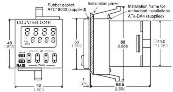

- Dimensions for front panel installations

( ) Dimensions for 8-pin type.
• Installation panel cut-out dimensions
The standard panel cut-out dimensions are shown below. Use the installation frame (AT8-DA4) and rubber gasket (ATC18002).

- For connected installations

Note 1: The installation panel thickness should be between 1 and 5 mm (.039 and .197 inch). Note 2: For connected installations, the waterproofing ability between the unit and installation panel is lost.
TERMINAL LAYOUT AND WIRING
- 8 pin type


- 11 pin type
Relay output type Transistor output type Relay output type Transistor output type


- Screw-down terminal type

Note: For connecting the output leads of the transistor output type, refer to 6) Transistor output on page 99.
SETTING THE OPERATION MODE AND COUNTER
Setting procedure 1) Setting the operation mode (input mode and output mode)
Set the input and output modes with the DIP switches on the side of the unit.
DIP switches
The new settings are valid after power OFF → ON
| Item | DIP switch | ||
| ONOFF | |||
| 1 | Operation mode Refer to table 1 | ||
| 2 | |||
| 3 | |||
| 4 | Minimum reset input signal width | 20 ms 1 ms | |
| 5 | Maximum counter setting 30 Hz 5 kHz | ||
| 6 | Input mode Refer to table 2 | ||
| 7 | |||
| 8 | |||
Table 1: Setting the output mode
| DIP switch No. | Output mode | ||
| 1 2 3 | |||
| ON ON ON SHOT-A | |||
| OFF OFF OFF SHOT-B | |||
| ON OFF OFF SHOT-C | |||
| OFF ON OFF SHOT-D | |||
| ON ON OFF HOLD-A | |||
| OFF OFF ON HOLD-B | |||
| ON OFF ON HOLD-C | |||
| OFF ON ON — | |||
See note 1

Table 2: Setting the input mode
| DIP switch No. | Input mode | ||
| 6 7 8 | |||
| ON ON ON Addition input | |||
| OFF OFF OFF Subtraction input | |||
| ON OFF OFF Directive input | |||
| OFF ON OFF Independent input | |||
| ON ON OFF Phase input | |||
| OFF OFF ON — | |||
| ON OFF ON — | |||
| OFF ON ON — | |||
See note 1
See note 1
See note 1
Note 1: The counter and set value displays will display DIP Err.
Note 2: Set the DIP switches before installing the unit.
Setting procedure 2) Setting the set value
Set the set value with the keys on the front of the unit.
Front display section
① Counter display ② Set value display ③ Controlled output indicator ④ Reset indicator ⑤ Lock indicator ⑥ UP keys
[Changes the corresponding digit of the set value in the addition direction (upwards)]

① Counter display ② Set value display ③ Controlled output indicator ④ Reset indicator ⑤ Lock indicator

⑦ DOWN keys Changes the corresponding digit of the set value in the subtraction direction (downwards) ⑧ RESET switch Resets the set value and the output ⑨ LOCK switch Locks the operation of all keys on the unit ⑥ UP keys Changes the corresponding digit of the set value in the addition direction (upwards) ⑦ RESET switch Resets the set value and the output ⑧ LOCK switch Locks the operation of all keys on the unit
- Changing the set value
- It is possible to change the set value with the up and down keys (4-digit type only) even during counting. However, be aware of the following points.
1) If the set value is changed to less than the count value with counting set to the addition direction, counting will continue until it reaches full scale (9999 with the 4-digit type and 999999 with the 6-digit type), returns to zero, and then reaches the new set value. If the set value is changed to a value above the count value, counting will continue until the count value reaches the new set value.
2) If counting is set to the subtraction direction, counting will continue until full scale (-999 with the 4-digit type and -99999 with the 6-digit type) regardless of the new set value, and then the display will change to ••••• with the 4-digit type and ••••••• with the 6-digit type.
- If the set value is changed to "0," the unit will not complete count-up. However, be aware of the following points.
1) When counting is set to the addition direction, counting will continue until full scale is reached (9999 with the 4-digit
type and 999999 with the 6-digit type), return to zero, and then complete count-up.
2) When counting is set to the subtraction direction, counting will continue until full scale is reached (-999 with the 4-digit type and -99999 with the 6-digit type), and then the display will change to • • • • • with the 4-digit type and • • • • • • with the 6-digit type. 3) For directive, independent, and phase input, when the counter value increases or decreases from the value "0" and then returns back to the value "0," count-up is completed.
OPERATION MODE
1. Input mode
For the input mode, you can choose one of the following five modes
- Addition
- Subtraction
- Directive
- Independent
- Phase UP DOWN DIR IND PHASE
| Input mode | Operation *Minimum input | signal width 30 Hz: 16.7 ms; 5 kHz: 0.1 ms |
| AdditionUP | IN1 or IN2 works as an input block (gate) for the other input. | Example where IN1 is the count input and IN2 is the input block (gate). Example where IN2 is the count input and IN1 is the input block (gate). Example where IN2 is the count input and IN1 is the input block (gate). * “A” must be more than the minimum input signal width. * “A” must be more than the minimum input signal width. |
| SubtractionDOWN | ||
| DirectiveDIR | IN1 is the count input and IN2 is the addition or subtraction directive input. IN2 adds at L level and subtracts at H level. |  * “A” must be more than the minimum input signal width. * “A” must be more than the minimum input signal width. |
| IndependentIND | IN1 is addition input and IN2 is subtraction input. |  * IN1 and IN2 are completely independent, so there is no restriction on signal timing. * IN1 and IN2 are completely independent, so there is no restriction on signal timing. |
| PhasePHASE | Addition when the IN1 phase advances beyond IN2, and subtraction when the IN2 phase advances beyond IN1. | 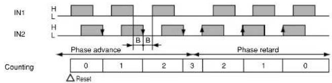 * “B” must be more than the minimum input signal width. * “B” must be more than the minimum input signal width. |
2. Output mode
For the operation mode, you can choose one of the following seven modes
- Maintain output/hold count HOLD-A
- Maintain output/over count I HOLD-B
- Maintain output/over count II HOLD-C
- One shot/over count SHOT-A
- One shot/recount I SHOT-B • One shot/recount II SHOT-C • One shot/hold count SHOT-D
| Output mode | Operation (Example when input mode is either addition or subtraction) | |
| Maintain outputHold countHOLD-A | Output control is maintained after count-up completion and until resetting. During that time, the count display does not change from that at count-up completion. | Counting (addition)---- n-3 n-2 n-1 n 3 2 1 0 Able UnableOFF ON* n: Set value |
| Counting (subtraction)---- 3 2 1 0 Counting able/unable Able UnableOFF ON* n: Set value | ||
| Maintain outputOver count IHOLD-B | Output control is maintained after count-up completion and until resetting. However, counting is possible despite completion of count-up. | Counting (addition)---- n-2 n-1 n+2n+1 2 1 0 - 2---- -1 Counting (subtraction)---- 2 1 0 - 2---- -1 Counting able/unable AbleOFF ON* n: Set value |
| Maintain outputOver count IIHOLD-C | Output control is maintained after count-up completion and until the next signal enters. However, counting is possible despite completion of count-up. | Counting (addition)---- n-2 n-1 n+2n+1 2 1 0 - 2---- -1 Counting (subtraction)---- 2 1 0 - 2---- -1 Counting able/unable AbleOFF ON* n: Set value |
| Counting (subtraction)---- 2 1 0 - 2---- -1 Counting able/unable AbleOFF ON* n: Set value | ||
| One shotOver countSHOT-A | Output control is maintained after count-up completion for a fixed time (approx. 1 sec). Counting is possible despite completion of count-up. | Counting (addition)---- n-2 n-1 n+2n+1 2 1 0 - 2---- -1 Counting (subtraction)---- 2 1 0 - 2---- -1 Counting able/unable AbleOFF ON* n: Set value |
| Counting (subtraction)---- 2 1 0 - 2---- -1 Counting able/unable AbleOFF ON* n: Set value | ||
| One shotRecount ISHOT-B | Output control is maintained after count-up completion for a fixed time (approx. 1 sec). Counting is possible despite completion of count-up. However, reset occurs simultaneous with completion of count-up. While output is being maintained, restarting of the count is not possible. | Counting (addition)---- 1n-2 n-1 0 2 1 n 2 n-1 n-2 ...Reset (automatic)AbleOFF ON* n: Set value |
| Counting (subtraction)---- 2 1 n n-1 n-2 ...Reset (automatic)AbleOFF ON* n: Set value | ||
| One shotRecount IISHOT-C | Output control is maintained after count-up completion for a fixed time (approx. 1 sec). Counting is possible despite completion of count-up. However, reset occurs simultaneous with output OFF. | Counting (addition)---- n-1 n 0 n+1 1 1 1 1 1 1 1 1 1 1 1 1 1 1 1 1 1 1 1 1 1 1 1 1 1 1 1 1 1 1 1 1 1 1 1 1 1 1 1 1 1 1 1 1 1 1 1 1 1 1 |
| Counting (subtraction)---- 1 0 n -1 n-1 1 1 1 1 1 1 1 1 1 1 1 1 1 1 1 1 1 1 1 1 1 1 1 1 1 1 1 1 1 1 1 1 1 1 1 1 1 1 1 1 1 1 1 1 1 1 1 1 1. | ||
| One shotHold countSHOT-D | Output control is maintained after count-up completion for a fixed time (approx. 1 sec). During that time, the count display does not change from that at count-up completion. Reset occurs simultaneous with output OFF. | Counting (addition)---- n-1 n 0 0 1 ----Counting (subtraction)---- 1 0 n n-1 n-1 1 1 1 1 1 1 1 1 1 1 1 1 1 1 1 1 1 1 1 1 1 1 1 1 1 1 1 1 1 1 1 1 1 1 1 1 1 1 1 1 1 1 1 1 1 1 1 2 |
| Counting able/unable Able UNable AbleOFF ON Approx. 1 s | ||
| Output control ONOFF* n: Set value | ||
PRECAUTIONS DURING USAGE
1. Terminal wiring
1) When wiring the terminals, refer to the terminal layout and wiring diagrams and be sure to perform the wiring properly without errors. 2) For embedded installation applications, the screw-down terminal type is recommended.
Use either the rear terminal block (AT8-RR) or the 8P cap (AD8-RC) for the 8-pin type, and the 11P cap (AT8-DP11) for the 11-pin type. Avoid soldering directly to the round pins on the unit. For front panel installation applications, use the 11-pin type DIN rail terminal block (ATC18004).
3) After turning the unit off, make sure that any resulting induced voltage or residual voltage is not applied to power supply terminals ② through ⑦ (8-pin type), ② through ⑩ (11-pin type) or ① and ⑬ (crew-down terminal type). (If the power supply wire is wired parallel to the high voltage wire or power wire, an induced voltage may be generated between the power supply terminals.) 4) Have the power supply voltage pass through a switch or relay so that it is applied at one time. If the power supply is applied gradually, the counting may malfunction regardless of the settings, the power supply reset may not function, or other such unpredictable occurrence may result.
2. Input connections
The power circuit has no transformer. When an input signal is fed to two or more counters at once, do not arrange the power circuit in an independent way. If the counter is powered on and off independently as shown in Fig. A, the counter's internal circuitry may get damaged. Be careful never to allow such circuitry. (Figs. A, B and C show the circuitry for the 11-pin type.)

If independent power circuitry must be used, keep the input contacts or transistors separate from each other, as shown in Fig. B. When power circuitry is not independent,

one input signal can be fed to two or more counters at once, as shown in Fig. C.
3. Input and output

1) Signal input type (1) Contact point input
Use highly reliable metal plated contacts. Since the contact point's bounce time leads directly to error in the count value, use contacts with as short a bounce time as possible. In general, select Input 1 and Input 2 to have a maximum counting speed of 30 Hz and to be reset with a minimum input signal width of 20 ms.
(2) Non-contact point input

Note: The LC4H-W does not have the lock input ④ ⑦
Connect with an open collector. Use transistors whose characteristics satisfy the criteria given below.
VCEO = 20 V min.
Ic=20\ mA\ min.
ICBO = 6µA .
Also, use transistors with a residual volt-
age of less than 2 V when the transistor is on. * The short-circuit impedance should be
![graph TD A["Reset input"] --> B["Input 1"] A --> C["Input 2"] A --> D["Lock input"] B --> E["8-pin type"] C --> F["11-pin type"] D --> G["Screw terminal type"] E --> H["①-543"] F --> I["③-567"] G --> J["678910"] H --> K["○"] I --> L["○"] J --> M["□"] K --> N["○"] L --> O["□"]](/content/2026/06/1359128/images/eac9d4d0c81173cb274da6cb014a44889227e62e1f0fd8fa8944d369225ed549.jpg)
Note: The LC4H-W does not have the lock input.
less than 1 kΩ.
[When the impedance is 0 Ω, the current coming from the input 1 and input 2 terminals is approximately 12 mA, and from the reset input and lock input terminals is approximately 1.5 mA.]
Also, the open-circuit impedance should be more than 100 kΩ.
* As shown in the diagram below, from a non-contact point circuit (proximity switches, photoelectric switches, etc.) with a power supply voltage of between 12 and 40 V, the signal can be input without using an open collector transistor. In the case of the diagram below, when the non-contact point transistor Q switches from off to on (when the signal voltage goes from high to low), the signal is input. 2) The input mode and output mode

(The above example is for reset input)
change depending on the DIP switch settings. Therefore, before making any connections, be sure to confirm the operation mode and operation conditions currently set.
3) For the power supply of the input
device, use a single-phase or double-phase insulated power transformer. The second-phase side must not be grounded.
4) Since the power supply circuitry does
![graph TD A["LC4H counter"] --> B["Input terminals"] B --> C["Circuit"] C --> D["Rectifier circuits"] D --> E["Power supply"] F["Insulated transformer is necessary"] --> D style A fill:#f9f,stroke:#333 style B fill:#ccf,stroke:#333 style C fill:#cfc,stroke:#333 style D fill:#fcc,stroke:#333 style E f…](/content/2026/06/1359128/images/c66514b2ef1bd91c56379a304415ad449a8aaeb00a1732e1e692fb0bae1b0750.jpg)
not contain a transformer, be aware that it is not possible for simultaneous input from an input contact point or transistor to a LC4H counter with independent power supply operation.
5) The input signal is applied by the shorting of each input terminal with the common terminal (terminal 1 for 8-pin type, terminal 3 for 11-pin type and terminal 6 for screw-down terminal types). Never connect other terminals or voltages higher than DC 40 V, because it may destroy the internal circuitry.
6) Transistor output
(1) Since the transistor output is insulated from the internal circuitry by a photo-coupler, it can be used as an NPN output or PNP (equal value) output. (The above example is 11-pin type) (2) Use the diode connected to the out-

Load's power supply

Load's power supply
Note: With the LC4H 8-pin type and the LC4H-W, there is no diode between points ⑧ and ⑨.
Put the transistor's collector for absorbing the reverse voltage from induced loads. (LC4H only)
7) When wiring, use shielded wires or

metallic wire tubes, and keep the wire lengths as short as possible.
4. Output mode setting
The output mode can be set with the DIP switches on the side of the counter. Make the DIP switch settings before installing the counter on the panel.
5. Conditions of usage
1) Avoid locations subject to flammable or corrosive gases, excessive dust, oil, vibrations, or excessive shocks. 2) Since the cover of the unit is made of polycarbonate resin, avoid contact with or use in environments containing methyl alcohol, benzene, thinners, and other organic solvents; and ammonia, caustic sodas, and other alkaline substances. 3) If power supply surges exceed the values given below, the internal circuits may become damaged. Be sure to use surge absorbing element to prevent this from happening.
| Operating voltage | Surge voltage (peak value) |
| AC type 6,000V | |
| DC type24V AC type | 1,000V |
- Surge wave form
[± (1.2 ×50) ms uni-polar full wave voltage]

4) Regarding external noise, the values below are considered the noise-resistant voltages. If voltages rise above these values, malfunctions or damage to the internal circuitry may result, so take the necessary precautions.
| Power supply terminals | Input terminals | ||
| AC type | DC type24V AC type | ||
| Noise voltage | 1,500V 1,000V 600V | ||
Noise wave form (noise simulator)
Rise time: 1 ns
Pulse width: 1 μs, 50 ns
Polarity: ±
Cycle: 100 cycles/second
5) When connecting the operation power supply, make sure that no leakage current enters the counter. For example, when performing contact protection, if set up like that of diagram A, leaking current will pass through C and R, enter the unit, and cause incorrect operation.
Diagram B shows the correct setup.
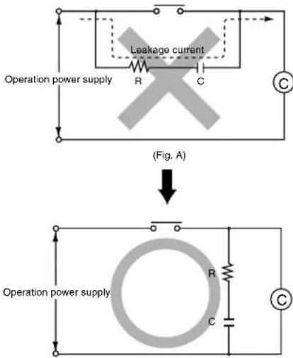
(Fig. B)
6) Long periods of continuous operation in the count-up completed condition (one month or more) will result in the weakening of the internal electrical components from the generated heat and, therefore, should be avoided. If you do plan to use the unit for such continuous operation, use in conjunction with a relay as shown in the circuit in the diagram below.

6. Self-diagnosis function
If a malfunction occurs, one of the following displays will appear.
| Display Contents | Output condition Restoration procedure Preset values after restoration | |||
| Minimum value went below -999 or -99999. See note 1. | No change | Enter reset or RESET key. | No change | |
| Incorrect DIP switch setting. | Restart unit (correct DIP switch settings) | |||
| Malfunctioning CPU. | OFF | Enter reset, RESET key, or restart unit. | The values at start-up before the CPU malfunction occurred. | |
| Malfunctioning memory. See note 2. | 0 | |||
Note 1: When the counter value goes below the minimum value during any of the subtraction, directive, independent, or phase input modes. Note 2: Includes the possibility that the EEPROM's life has expired.
7. CE Marking Certification
1) EMC directive (89/336/EEC) As a counter unit, the LC4H series conforms to EMC directives. Applicable standards are EN50081-2 and EN50082-2. 2) Low voltage directive (73/23/EEC) In order to satisfy VDE0435/Part 2021, be sure to adhere to the following installation conditions and precautions. (1) The counter uses a non-transformer power supply and the power supply and input signal terminals are not insulated. - When a sensor is connected to the
input circuit, install double insulation on the sensor side.
- With contact-point inputting, use double-insulated relays, etc. (2) Always connect loads insulated with basic insulation specifications to the output contact points. The counter unit is also insulated with basic insulation specifications. The combination of the two satisfies VDE, which calls for double insulation. (3) For the applied power supply, use one protected by an over-current protec-
tion device that conforms with EN/IEC standards (e.g. 250 V, 1 A fuse).
(4) During installation, always use a terminal block or the appropriate sockets.
Do not touch the terminals or any other part of the counter unit while it is on. Before installing or removing the unit, first verify that no voltage is applied to any of the terminals.
(5) Do not use the counter in a safety circuit. When the unit is used in a circuit such as a heater circuit, install a protection circuit on the machine side.
- FEATURES
- BRIGHT AND EASY-TO-READ DISPLAY
- SIMPLE OPERATION
- SHORT BODY OF ONLY 64.5 MM (2.539 INCHES)
- CONFORMS TO IP66'S WEATHER
- RESISTANT STANDARDS
- SCREW TERMINAL AND PIN TYPE ARE BOTH STANDARD OPTIONS
- CHANGEABLE PANEL COVER
- DIGIT OR 6-DIGIT DISPLAY
- CONFORMS WITH EMC AND LOW VOLTAGE DIRECTIVES
- DIMENSIONS (UNITS: MM INCH)
- DIMENSIONS FOR EMBEDDED INSTALLATION (WITH ADAPTER INSTALLED)
- INSTALLATION PANEL CUT-OUT DIMENSIONS
- TERMINAL LAYOUT AND WIRING
- PIN TYPE
- SCREW-DOWN TERMINAL TYPE
- SETTING THE OPERATION MODE AND COUNTER
- SETTING PROCEDURE 2) SETTING THE SET VALUE
- FRONT DISPLAY SECTION
- CHANGING THE SET VALUE
- OPERATION MODE
- INPUT MODE
- OUTPUT MODE
- PRECAUTIONS DURING USAGE
- TERMINAL WIRING
- INPUT CONNECTIONS
- INPUT AND OUTPUT
- OUTPUT MODE SETTING
- CONDITIONS OF USAGE
- SURGE WAVE FORM
- SELF-DIAGNOSIS FUNCTION
- CE MARKING CERTIFICATION
Brand : PANASONIC
Model : LC4H
Category : Measuring equipment