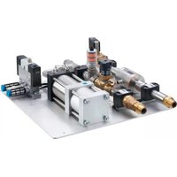
ZZ0432 - Temperature regulator IFM - Free user manual and instructions
Find the device manual for free ZZ0432 IFM in PDF.


| Product Type | Industrial Sensor / Controller |
| Model | ZZ0432 |
| Brand | IFM |
| Dimensions (approx.) | 80 mm x 50 mm x 30 mm |
| Weight | 120 g |
| Power Supply | 24 V DC |
| Power Consumption | 2 W |
| Protection Class | IP67 |
| Operating Temperature | -25°C to +70°C |
| Output Type | PNP/NPN programmable |
| Main Functions | Detection, monitoring, switching signal |
| Display | 2-line LED, 4-digit |
| Connection | M12 connector, 4-pin |
| Housing Material | Stainless steel / PBT |
| Maintenance | Periodic cleaning with dry cloth |
| Cleaning | Use mild detergent, no solvents |
| Safety | CE marked, RoHS compliant |
| Spare Parts | Available from IFM distributors |
| Repairability | Factory repair only; no user-serviceable parts |
| General Information | Refer to user manual for detailed installation |
Frequently Asked Questions - ZZ0432 IFM
User questions about ZZ0432 IFM
0 question about this device. Answer the ones you know or ask your own.
Ask a new question about this device
Download the instructions for your Temperature regulator in PDF format for free! Find your manual ZZ0432 - IFM and take your electronic device back in hand. On this page are published all the documents necessary for the use of your device. ZZ0432 by IFM.
USER MANUAL ZZ0432 IFM
Operating instructions
Cooling water control panel
ZZ0432
Contents
1 Preliminary note 3
1.1 Symbols used 3
2 Safety instructions 4
2.1 Cybersecurity.... 4
3 Transport, handling and storage 5
4 Intended use 6
5 Function 7
5.1 Flow rate monitoring (flow meter) 8
5.2 Failure detection (pressure sensor) 9
6 Installation 10
7 Electrical connection 11
8 Parameter setting.... 12
8.1 Flow monitoring 12
8.2 Pressure monitoring 14
9 Factory setting 15
1 Preliminary note
You will find instructions, technical data, approvals and further information using the QR code on the unit / packaging or at → documentation.ifm.com.
1.1 Symbols used
√ Requirement
Instruction
Reaction, result
bold Designation of keys, buttons or indications
→ Cross reference without link ("See")
Link in document or link to the internet
Important note Non-compliance may result in malfunction or interference
Information Supplementary note
2 Safety instructions
- The unit described is a subcomponent for integration into a system.
– The system architect is responsible for the safety of the system.
– The system architect undertakes to perform a risk assessment and to create documentation in accordance with legal and normative requirements to be provided to the operator and user of the system. This documentation must contain all necessary information and safety instructions for the operator, the user and, if applicable, for any service personnel authorised by the architect of the system. - Read this document before setting up the product and keep it during the entire service life.
- The product must be suitable for the corresponding applications and environmental conditions without any restrictions.
- Only use the product for its intended purpose (→ Intended use).
- Only use the product for permissible media.
- If the operating instructions or the technical data are not adhered to, personal injury and/or damage to property may occur.
- The manufacturer assumes no liability or warranty for any consequences caused by tampering with the product or incorrect use by the operator.
- Installation, electrical connection, set-up, operation and maintenance of the product must be carried out by qualified personnel authorised by the machine operator.
- Protect units and cables against damage.
2.1 Cybersecurity
Installation
The device is suitable for operation in a secure environment according to IEC 62443-1-1.
The device was designed for operation behind a firewall.
Carry out a risk assessment of the system according to IEC 62443-1-1.
▶ Take measures to ensure physical security.
Operation
▶ Observe the security functions described in the product documentation and the recommendations for their use.
Maintenance
Back up system configuration and system data in accordance with your company's change management processes.
Decommissioning
▶ Ensure that no sensitive information can fall into unauthorised hands.
▶ Always reset the system settings to the factory settings before decommissioning the device.
3 Transport, handling and storage
▶ Store the device in its original packaging.
When the device is to be stored again, use the original packaging.
▶ Otherwise, provide unused connections with either a mating connector or a protective cap and pack the device in suitable packaging.
▶ Observe the permissible ambient conditions for the device during storage (→ Technical data).
4 Intended use
The cooling water control panel (Cooling water control panel) is used to monitor and regulate cooling water systems.
The system can also detect flow disturbances, leakages or loss of a welding cap, for example when used in spot welding robots.
The sensors on the cooling water control panel detect the process variables flow and media temperature in the supply line and system pressure in the return line and transmit these process values to the controller.

Pressure Equipment Directive (PED):
The cooling water control panel complies with the Pressure Equipment Directive and is designed and manufactured for group 2 fluids in accordance with the sound engineering practice. Use of media from group 1 fluids on request.
5 Function

Fig. 1: System structure
| Component Function | ||
| 1: SM6000 flow meter Monitoring | and display of temperature, volume flow and consumed quantity (totaliser function) of cooling water.The sensor detects the following deviations from normal operation:Excess flow (leakage / burst pipe / lost cap)Low flow (clogged / damaged pipes)Temperature in the supply line | |
| 2: | Water stop valve Stops the water inflow in case of failure or maintenance. Leakage of cooling water in the supply line is prevented.Open during normal operation. | |
| 3: | Non-return valve Stops the water outflow in case of failure or maintenance (e.g. lost cap and burst pipe). Leakage of cooling water in the return line is prevented. | |
| 4: | Line regulator valve Continuous regulation of the flow rate | |
| 5: | Pressure sensor PK6524 Monitoring of the operating pressure. The sensor detects an abrupt pressure drop (lost cap) with a very fast response time. | |
| 6: | Expansion cylinder Active suction of water in case of failure or maintenance (e.g. cap replacement). No pressure is applied to the system and the water stop valves are closed during this process. | |
| 7: | 5/2-way valve Controls the expansion cylinder in case of failure or maintenance. | |
| 8: | Tube connection Diameter 8 mm. | |
Operating principle:
The cooling water circulates through the cooling water control panel and the robot or production machine in a closed circuit and is transported via pumps.
The sensors monitor the flow of the cooling water in the supply line as well as the operating pressure of the cooling water in the return line. The process values of the sensors are transmitted to the controller.
5.1 Flow rate monitoring (flow meter)
The required flow rate (acceptable range) is set using the line regulator valve. For this purpose, the value is read from the display of the flow meter.
The flow meter uses the window function (acceptable range) to monitor the flow in the supply line and signals deviations from the set acceptable range (excess flow or low flow) via its two hardware outputs.
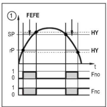
line
| Time | Value | |------|-------| | t | 0 | | Fno | 1 | | Fnc | 1 |1: Process value
t: Time
SP: Upper limit value
rP: Lower limit value
HY: Hysteresis
Fno: Window function NO (normally open)
Fnc: Window function NC (normally closed)
Fig. 2: Window function

The flow depends on the water supply and the design of the welding gun.
Setting of the SP1 and SP2 setpoints and of the rP1 and rP2 reset points must be adapted to the specific conditions of the system.

Setpoint and reset point configuration: Flow monitoring [→ 12].
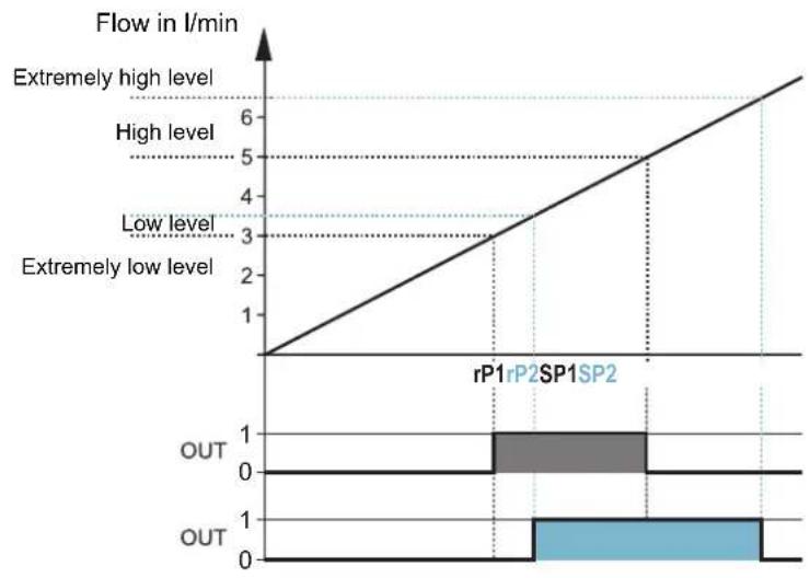
line
| Flow in l/min | Value | | ------------- | ----- | | Extremely high level | 6 | | High level | 5 | | Low level | 4 | | Extremely low level | 3 | | rP1rP2SP1SP2 | 1 | | OUT | 1 | | OUT | 0 |Fig. 3: Operating principle of the flow monitoring (example).
5.2 Failure detection (pressure sensor)
The pressure sensor monitors the operating pressure of the cooling water in the return line.
In the event of a failure (e.g. a lost cap or burst pipe), any interruption in the cooling water circuit is signalled by the pressure sensor with a very fast response time to the controller.
- The switch point is to be set to a value just below the operating pressure to achieve the shortest possible response time. Ensure that pressure fluctuations due to the system do not trigger a switching operation.
- Outputs OUT1 and OUT2 complement each other: In case of increasing pressure, OUT1 closes / OUT2 opens when the set Set value is reached. In case of decreasing pressure, OUT1 opens / OUT2 closes when the set Reset value is reached.
The controller causes the water stop valve to close and the 5/2-way valve to control the expansion cylinder. The expansion cylinder actively sucks the remaining cooling water from the robot's pipes.

The pressure conditions in the return line depend on the water supply.
Setting of the Set setpoint and of the Reset reset point must be adapted to the specific conditions of the system.

Setpoint and reset point configuration: Pressure monitoring [→ 14].
6 Installation
▶ Screw the cooling water control panel to a flat surface, a panel, a frame (Frame mounted solution) or to the robot base using the drill holes in the mounting plate.
▶ Connect the 4 process connections of the cooling water control panel to the cooling water circuit.
▶ Adhere to the flow direction during installation (black arrow mark).
7 Electrical connection

The devices must be connected by a qualified electrician.
▶ Observe the national and international regulations for the installation of electrical equipment.
▶ Adhere to the instructions enclosed to the individual devices.
▶ Disconnect power.
▶ Connect the sensors, the water stop valve and the 5/2-way valve to the controller via M12 connectors.
8 Parameter setting
8.1 Flow monitoring
The parameters of the flow meter can be set via the IO-Link interface or by using the keys on the device.
Code for the robot software:
| Code Explanation | |
| REAL W_ZEIT_EX_ZUW_Z1=2.0 Monitoring time in seconds for extremely low water level | |
| REAL W_ZEIT_ZUW_Z1=10.0 Monitoring time in seconds for low water level | |
| REAL W_ZEIT_EX_ZUV_Z1=1.0 Monitoring time in seconds for extremely high water level | |
| REAL W_ZEIT_ZUV_Z1=10.0 Monitoring time in seconds for high water level | |
| REAL W_ZEIT_EX_ZUW_ST_Z1=5.0 Extremely low water level when the water starts to flow | |
| REAL W_ZEIT_ZUW_ST_Z1=20.0 Low water level in seconds when the water starts to flow | |
| REAL W_ZEIT_DRUCK_Z1=1.0 Monitoring time in seconds – pressure fault | |
| REAL W_ZEIT_DRUCK_ST_Z1=2.0 Pressure fault when the water starts to flow | |
Setting the flow on the line regulator valve:
▶ Set the required flow rate by slowly turning the line regulator valve (acceptable range).
▶ Read the value on the flow meter display.

The valve position is indicated on the front of the handwheel by a scale ranging from 0.0 (closed) to 4.85 (fully open), in increments of 0.05.
To reduce the flow: Turn the valve clockwise.
To increase the flow: Turn the valve anticlockwise.
Configuring switch points on the flow meter:
▶ Use the device keys [→ 12] or the IO-Link interface [→ 13] to set the upper threshold (SP) and the lower threshold (rP) of the acceptable range.
8.1.1 Configuring the flow meter using the device keys
Parameter setting process in general:
| Intention Action | |
| Change from the process value display to the main menu Mode/Enter | |
| Change to the submenu EF | Use Mode/Enter to navigate to EF, then Set |
| Select the required parameter Mode/Enter | |
| Change to the setting mode | Set > 5 seconds |
| Modify the parameter value• Incrementally by pressing once• Continuously by keeping the button pressed• To reduce the value: let the display move to the maximum setting value. Then the cycle starts again at the minimum setting value. | Set |
| Apply the set parameter | Mode/Enter |
| Return from the EF submenu to the main menu | Mode/Enter |
| Return from the main menu to the process display Mode/Enter | |
| Return to the process value display > 30 seconds (timeout) |
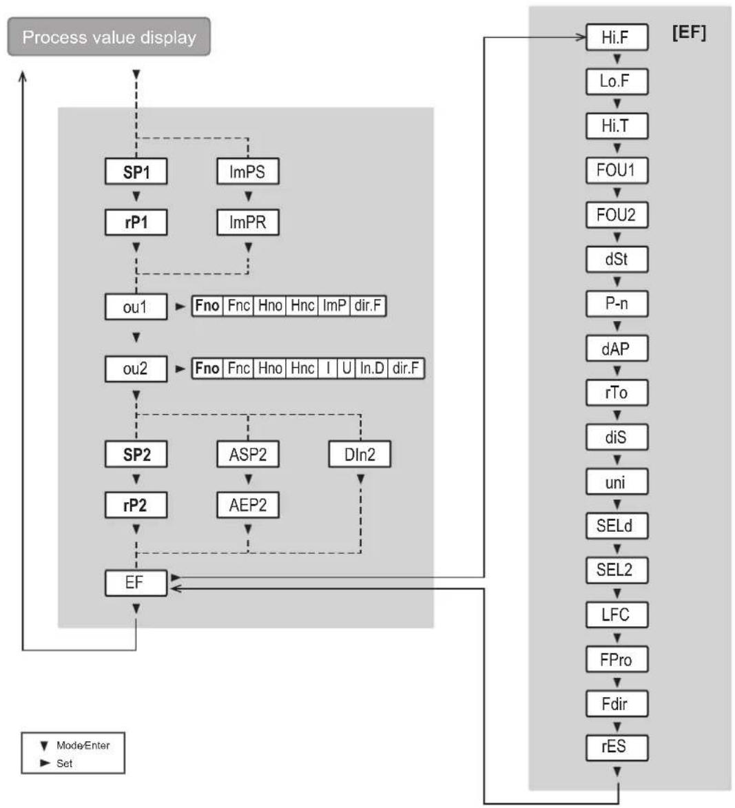
flowchart
graph TD
    A["Process value display"] --> B["SP1"]
    A --> C["ImPS"]
    B --> D["rP1"]
    C --> E["ImPR"]
    D --> F["ou1"]
    E --> F
    F --> G["ou2"]
    G --> H["SP2"]
    G --> I["ASP2"]
    G --> J["DIn2"]
    H --> K["rP2"]
    I --> L["AEP2"]
    J --> M["EF"]
    M --> N["EF"]
    N --> O["Hi.F"]
    O --> P["Lo.F"]
    P --> Q["Hi.T"]
    Q --> R["FOU1"]
    R --> S["FOU2"]
    S --> T["dSt"]
    T --> U["P-n"]
    U --> V["dAP"]
    V --> W["rTo"]
    W --> X["diS"]
    X --> Y["uni"]
    Y --> Z["SELd"]
    Z --> AA["SEL2"]
    AA --> AB["LFC"]
    AB --> AC["FPro"]
    AC --> AD["Fdir"]
    AD --> AE["rES"]
    AE --> AF["[EF"]]
    style AF fill:#f9f,stroke:#333,stroke-width:2px
    note right of AF
        Mode/Enter
        Set
    end
Fig. 4: Menu structure for configuration via the device keys
8.1.2 Configuring the flow meter via IO-Link
The device parameters can be set via the IO-Link interface in the following ways, for example:
- Parameter setting via a suitable parameter setting software, e.g. ifm moneo|configure
- Parameter setting via a PLC
- Parameter setting via an IIoT application
Requirements for parameter setting via the IO-Link interface:
√ The Input Output Device Description (IODD) for the device in case of parameter setting via a parameter setting software, see ➕ documentation.ifm.com
√ The IO-Link interface description (PDF) for the device in case of parameter setting via a PLC or IIoT application, see ➕ documentation.ifm.com
√ An IO-Link master
Connect the IO-Link master to the parameter setting software, the PLC or the IIoT application.
Connect the device to a suitable free port of the IO-Link master.
▶ Set the port of the IO-Link master to the IO-Link operating mode.
The device changes to the IO-Link mode.
▶ Change the parameter settings in the software.
▶ Write the parameter settings to the device.

Support for system integration and parameter setting via IO-Link:
→ Manual of the parameter setting software (e.g. moneo)
Explanations and startup packages at ifm.com/cnt/io-link-system-integration.
8.2 Pressure monitoring
The pressure sensor is configured using the setting rings on the device.

Fig. 5: Setting the switch points of the pressure sensor
▶ Release the locking ring (1).
▶ Set the setpoint using the setting ring Set (2).
▶ Set the reset point using the setting ring Reset (3).
▶ Close the locking ring (1).
9 Factory setting
Flow meter:
| Parameter Factory setting | |
| SP1 5.0 | |
| rP1 3.0 | |
| ImPS 0.05 | |
| ImPR YES | |
| ou1 Fno | |
| ou2 Fno | |
| SP2 (FLOW) 6.5 | |
| rP2 (FLOW) 3.5 | |
| SP2 (TEMP) 20.0 | |
| rP2 (TEMP) 19.6 | |
| ASP (FLOW) 0.00 | |
| AEP (FLOW) 25.00 | |
| ASP (TEMP) -20.0 | |
| AEP (TEMP) 80.0 | |
| DIn2 +EDG | |
| FOU1 | OFF |
| FOU2 | OFF |
| dSt | 0 |
| P-n PnP | |
| dAP | 0.6 |
| rTo | OFF |
| diS | d2 |
| Uni | Lmin |
| SELd FLOW | |
| SEL2 FLOW |
Pressure sensor:
| Parameter Factory setting | |
| SP1 2.0 | |
| rP1 1.5 |
- Contents
- Preliminary note
- Symbols used
- Safety instructions
- Cybersecurity
- Installation
- Operation
- Maintenance
- Decommissioning
- Transport, handling and storage
- Intended use
- Function
- Operating principle:
- Flow rate monitoring (flow meter)
- Failure detection (pressure sensor)
- Installation
- Electrical connection
- Parameter setting
- Flow monitoring
- Setting the flow on the line regulator valve:
- Configuring switch points on the flow meter:
- Configuring the flow meter using the device keys
- Configuring the flow meter via IO-Link
- Pressure monitoring
- Factory setting
Brand : IFM
Model : ZZ0432
Category : Temperature regulator