
WV-ASM300W - Software license and extension PANASONIC - Free user manual and instructions
Find the device manual for free WV-ASM300W PANASONIC in PDF.


| Product Type | Software License and Extension |
| Brand | Panasonic |
| Model | WV-ASM300W |
| Compatibility | Panasonic WV-ASM300 series security management system |
| License Type | Per server (individual license) |
| Number of Licenses | 1 license per unit |
| Software Version | Latest version as of purchase |
| Language Support | English, French, German, Spanish, Italian, Japanese, Chinese (Simplified) |
| System Requirements | Windows 10 Pro/Enterprise (64-bit), 8 GB RAM, 500 GB HDD, Intel Core i5 or equivalent |
| Installation Method | Digital download with product key |
| Updates | Free updates for 1 year from purchase date |
| Technical Support | Email and phone support during business hours |
| License Activation | Online activation via Panasonic portal |
| License Transfer | Transferable once to another server upon deactivation |
| Usage Rights | Single server installation, up to 5 client connections |
Frequently Asked Questions - WV-ASM300W PANASONIC
User questions about WV-ASM300W PANASONIC
0 question about this device. Answer the ones you know or ask your own.
Ask a new question about this device
Download the instructions for your Software license and extension in PDF format for free! Find your manual WV-ASM300W - PANASONIC and take your electronic device back in hand. On this page are published all the documents necessary for the use of your device. WV-ASM300W by PANASONIC.
USER MANUAL WV-ASM300W PANASONIC
Operating Instructions
Video Surveillance Software
Model No. WV-ASM300, WV-ASM300W
Extension Software
Model No. WV-ASE202, WV-ASE203
WV-ASE204, WV-ASE205
WV-ASE231, WV-ASE306
WV-ASE202W, WV-ASE203W
WV-ASE204W, WV-ASE205W
WV-ASE231W, WV-ASE306W
Concurrent User License Kit
Model No. WJ-NXC05W
CONTENTS
1. Preface 4
1.1. About the user manual ....4
1.2. Preface 4
1.3. System configuration diagram 4
1.4. System specifications 5
1.5. Compatible devices 6
1.6. Features 12
1.7. Standard accessories 13
1.8. System requirements 13
1.9. Recommended camera settings when monitoring MPEG-4, H.264 or H.265 images 15
1.10. Restriction when using Smart Coding 17
1.11. About use of open source software 18
1.12. License 21
1.13. Trademarks and registered trademarks 21
1.14. Abbreviations 21
1.15. Precautions for use 22
1.16. Document convention 22
2. Preparation 29
2.1. From installation to start operation 29
2.2. Installation/uninstallation 32
2.3. Launching and terminating this software 34
2.4. Upgrade this software 44
2.5. ASM300 main screen description 45
2.6. Operation window description 52
3. Setup Instructions 82
3.1. Setup window description 82
3.2. Settings relating to the system 85
3.3. Settings relating to the device management 105
3.4. Settings relating to the user management 222
3.5. Settings relating to folder 239
3.6. Settings relating to group 248
3.7. Settings relating to sequence 260
3.8. Settings relating to the default screen 270
3.9. Settings relating to map 273
3.10. Settings relating to the face search 282
3.11. Settings relating to the event action 293
3.12. Settings relating to the communication 304
3.13. Settings relating to the controller 306
3.14. Settings relating to maintenance 313
3.15. Settings relating to the license registration 335
3.16. Exceptional settings of Windows Firewall 338
3.17. Set the installation method of fisheye cameras 342
4. Operating Instructions 347
4.1. Use the operation window 347
4.2. Use the SD log display/playback window 402
4.3. Use the live window 408
4.4. Use the map window 416
4.5. Use the search window 427 4.6. Use the visibility enhancement function 446 4.7. Use the face search monitor 462 4.8. Use the heat map display function 517 4.9. Control a decoder 531 4.10. Use the download function 536 4.11. Use the viewer software 553 4.12. Alarm/event notification 559
- System controller (WV-CU950) 567
5.1. Set a system controller 568 5.2. Operation using the system controller 570
- Concurrent User License Kit (WJ-NXC05W) 573
6.1. Precautions 573 6.2. Setting relating to the license recorder 575 6.3. Login to this software with Concurrent User License 587
- Troubleshooting 589
- Displayed messages and solutions 597
8.1. When this software is launched 597 8.2. When the [OK] button on the login window is clicked 597 8.3. When the [OK] button on the "Change password" window is clicked 597 8.4. When the [Go to date] button on the "Quick playback" panel is clicked 598 8.5. When the [Download] button on the "Download" panel is clicked 598 8.6. When the [OK] button is clicked on the "Select folder" window 598 8.7. When the [Audio transmission] button is clicked 599 8.8. When an error occurred 599 8.9. When the [Image display] button on the VMD search tab is clicked 599 8.10. When the [List/Play] button of the [SD] tab page is clicked or when [Event] ([Alarm], [Manual/Schedule]) on the playback window is selected.... 600
8.11. When the [Set] button is clicked 600 8.12. When the [Delete] button is clicked 602 8.13. When downloading the device information 602 8.14. When the live image source is selected on the "Camera setup" window 604 8.15. When the [OK] button on the camera setup page is clicked 604 8.16. When dragging and dropping the icon on the map creation window 605 8.17. When the [Download] button on the "Recorder log" window is clicked 605 8.18. When the [Save] button on the "Save As" window is clicked 605 8.19. When determined the entered number on the setting pages of "Controller" 605 8.20. When using File conversion 606
Preface 1.
About the user manual 1.1.
- This document refers to WVASE202 and WVASE202W as WVASE202, WVASE203 and WVASE203W as WVASE203, WVASE204 and WVASE204W as WVASE204, WVASE205 and WVASE205W as WVASE205, WVASE231 and WVASE231W as WVASE231, WVASE306 and WVASE306W as WVASE306.
- The descriptions in the following pages are based on the assumption that Microsoft® Windows® 10 Professional runs on a PC. Operation windows may not be the same as those appearing on the pages when a different OS is used or different settings are applied. When using other OS, refer to the operating instructions of the respective OS.
This manual explains using this software outside Japan. When using this software in Japan, please read the instruction manual for Japan.
Video Surveillance Software WV-ASM300 series (hereinafter, this software) is designed for integrated management of multiple devices (Refer to "System specifications" for the maximum number of registration of each device.) of Panasonic network disk recorders and digital disk recorders (hereinafter, recorder(s)), network interface units (hereinafter, encoder(s)), network cameras (hereinafter, camera(s)) connected to a LAN (Local Area Network, hereinafter, network), and runs on Microsoft Windows operating system. Refer to "Compatible devices" for the devices compatible with this software.
By using this software on a personal computer (hereinafter PC) via a network, it is possible to display live images of the cameras on monitors, to play audio from microphones on a PC, to play images and audio stored on the recorder, and to download image files to the hard disk drive of the PC.
*1 When a system that is surrounded by the dash-lines in the above diagram is configured, it is possible to directly monitor images from cameras that are connected to recorders without processing through recorders. In this case, check and set the following items.
directly monitor images from cameras that is connected to recorders without processing through recorders. In this case, check and set the following items.
- Register cameras in the recorder.
- The recorder should be used with a single port.
*2 A system controller is to be purchased separately.
Important:
- Do not use cross cables to connect the PC and each device.
- When connecting multiple system controllers, operation of this software is not guaranteed.
• Number of recorder registration: Up to 100 recorders • Number of encoder registration: Up to 64 encoders • Number of camera registration: Up to 256 cameras • Number of microphone registration: Up to 256 microphones • Number of user registration: Up to 32 users • Number of user levels: 6 levels • Number of group registration: - Number of sequence registration: Up to 20 sequences (Up to 64 steps can be registered per sequence) - Number of map registration: Up to 100 maps (Up to 128 camera icons can be assigned on a map, up to 20 registered map icons can be used. The file size shall be less than 10 MB. Available file types are JPEG, BMP and PNG.) • Number of the alarm logs that can be stored (Number that can be displayed): Up to 30000 logs (Up to 1000 logs) • Number of the device error logs that can be stored (Number that can be displayed): Up to 1000 logs (Up to 1000 logs) • Number of the network error logs that can be stored (Number that can be displayed): Up to 1000 logs (Up to 1000 logs) • Number of the system logs that can be stored (Number that can be displayed): Up to 1000 logs (Up to 1000 logs) • Number of the operation logs that can be stored (Number that can be displayed): Up to 100000 logs (Up to 1000 logs) • Number of search results: Up to 1000 results (Up to 200 results for VMD search)
Note:
- The number of PCs that can concurrently access a single recorder differs depending on whether the "Live window" is used and the model of the device in use.
- However, when "Timeline display" is set to "On", the number of connectible PCs will be one less than the number in the table below. Refer to "System" - "Timeline" for further information about the "Timeline".
- When using the download function, the number of connectible PCs will be one less than the number in the table below. Refer to "Use the download function" for further information about the download function.
- The table below shows the number of PCs that can access a single recorder when using a single "Live window". The PC(s) can be connected if the total number of operation windows and live windows is less than the maximum number of connected PCs when the live window is not used.
| Device | Use of live window | |
| Use Not use | ||
| ND300 4 6 | ||
| ND200 2 4 | ||
| HD300 (*3) 2(*1) 3 (*2) | ||
| ND400 8 16 | ||
| HD600 4 8 | ||
| NV200 1 1 | ||
| NV300 4 8 | ||
| NX200 (*4) | 8 | 16 |
| NX300 (*4) 8 16 | ||
| NX400 (*4) 8 16 | ||
| Video Insight Server (*5) (*5) | ||
*1 When displaying images on a 16-screen or 9-screen, only a single PC can access. *2 When displaying images on a 16-screen, 2 PCs can access. *3 Under the following conditions, connection to the recorder may be interrupted and a black screen may be displayed.
- When event recording and sequence are being operated • The total live rate for each HD300 is 15 ips or more
*4 In the case of NX-series recorder, selecting "Camera" for "Live image source" does not include the live window in the number of users even when using the live window. *5 Note that it varies depending on the system configuration in use.
- When exceeding the maximum number of concurrent access due to an increase in the number of accesses using web browsers or FTP accesses, connection to the recorder may be interrupted and a black screen may be displayed.
- By adding the license for the Extension Software WV-ASE203 (option), it will become possible to expand the maximum numbers of registered recorders, encoders, cameras and microphones to 100, 64, 256 and 256 respectively. This license can be used for up to 4 registrations.
Compatible devices 1.5.
The following devices are compatible with this software.
Important:
- Some functions may not work depending on the firmware version of the compatible device. Refer to the Panasonic support website for further information. https://security.panasonic.com/support/
Note:
- Refer to the operating instructions of the recorder in use for the cameras and microphones that can be connected to the recorder in use.
- Recorders that support use of microphones are NV300 series, NV250 series, ND400, NX400 (version 2.0 or later), NX300 and NX200 (version 1.1 or later). The available functions vary depending on the firmware version of the recorder. Refer to the operating instructions of the recorder for further information.
- For cameras that can be interlocked with the microphone, please read the owner's manual of your camera.
Compatible recorders 1.5.1.
| Model Appears in this document as | Version Compression | ||
| WJ-ND300, WJ-ND300A | ND300 | 5.20 or later | MPEG-4, M-JPEG, H.264 |
| WJ-ND200 | ND200 | 3.35 or later | MPEG-4, M-JPEG, H.264 |
| WJ-HD309A, WJ-HD316A | HD300 | 3.45 or later | Model-specific |
| WJ-ND400, WJ-ND400K | ND400 | 5.50 or later | MPEG-4, M-JPEG, H.264 |
| WJ-HD616K, WJ-HD716K | HD600 | 2.70 or later | H.264 |
| DG-NV200 series | NV200 | 2.60 or later | MPEG-4, M-JPEG, H.264 |
| WJ-NV300 series | NV300 | 1.70 or later | M-JPEG, H.264 |
| WJ-NX200 series | NX200 | 1.00 or later | M-JPEG, H.264, H.265 |
| WJ-NX300 series | NX300 | 1.00 or later | M-JPEG, H.264, H.265 |
| WJ-NX400 series | NX400 | 1.01 or later | M-JPEG, H.264, H.265 |
| Video Insight Server | Video Insight Server | 6.xx.xx | H.264 |
Compatible encoder 1.5.2.
| Model Appears in | Version Compression | ||
| WJ-NT304 | NT304 | 1.32 or later | MPEG-4, M-JPEG |
| WJ-NT314 | NT314 | 1.32 or later | MPEG-4, M-JPEG |
| WJ-GXE500 | GXE500 | 2.41 or later | H.264, MPEG-4, M-JPEG |
| WJ-GXE100 | GXE100 | 2.40 or later | H.264, M-JPEG |
Compatible cameras 1.5.3.
| Model | Version |
| RP-NP244 (*1) | 1.81 or later |
| RP-NP1000/RP-NP1004 (*1) | 1.25 or later |
| WV-NS202 (*1) | 1.11 or later |
| WV-NS202A (*1) | 2.74 or later |
| WV-NF282 (*1) | 1.61 or later |
| WV-NW484 (*1) | 1.64 or later |
| WV-NS950 (*1) | 1.64 or later |
| WV-NW960 (*1) | 1.64 or later |
| WV-NP304 (*1) | 1.61 or later |
| WV-NF302 (*1) | 1.61 or later |
| WV-NP502 | 2.41 or later |
| WV-NW502S | 2.44 or later |
| WV-SP302 | 2.44 or later |
| WV-SP305 | 2.42 or later |
| WV-SP306 | 2.44 or later |
| WV-SF332 | 2.44 or later |
| WV-SF335 | 2.42 or later |
| WV-SF336 | 2.42 or later |
| WV-SP102 | 2.50 or later |
| WV-SP105 | 2.50 or later |
| WV-SC385 | 2.42 or later |
| WV-SW395 | 2.50 or later |
| WV-SF342 | 2.44 or later |
| WV-SF346 | 2.44 or later |
| WV-SC384 | 2.44 or later |
| WV-SW352 | 2.44 or later |
| WV-SW355 | 2.41 or later |
| WV-SW559 | 2.43 or later |
| WV-SW558 | 2.48 or later |
| WV-SW396/WV-SW396A | 2.41 or later |
| WV-SW316/ WV-SW316L | 2.41 or later |
| WV-SW314 | 2.41 or later |
| WV-SP509 | 2.43 or later |
| WV-SP508 | 2.48 or later |
| WV-SC386 | 2.41 or later |
| WV-SW152 | 2.50 or later |
| WV-SW155/WV-SW155MA | 2.41 or later |
| WV-SF135 | 2.41 or later |
| WV-SF132 | 2.41 or later |
| WV-ST165 | 4.62 or later |
| WV-ST162 | 4.62 or later |
| WV-SW175 | 4.62 or later |
| WV-SW174W | 4.62 or later |
| WV-SW172 | 4.62 or later |
| WV-SF549 | 2.48 or later |
| WV-SF548 | 2.48 or later |
| WV-SF539 | 2.48 or later |
| WV-SF538 | 2.48 or later |
| WV-SW458/ WV-SW458MA | 2.43 or later |
| WV-SF438 | 2.43 or later |
| WV-SF448E | 2.43 or later |
| WV-SW598/WV-SW598A | 2.43 or later |
| WV-SC588/WV-SC588A | 2.43 or later |
| WV-SF138 | 2.43 or later |
| WV-SW158 | 2.43 or later |
| WV-SFV631L/WV-SFV631LT | 2.52 or later |
| WV-SFV611L | 2.52 or later |
| WV-SFN631L | 2.52 or later |
| WV-SFN611L | 2.52 or later |
| WV-SFR631L | 4.00 or later |
| WV-SFR611L | 4.00 or later |
| WV-SW115 | 2.50 or later |
| WV-ST165A | 4.62 or later |
| WV-ST162A | 4.62 or later |
| WV-SPN631 | 2.52 or later |
| WV-SPN611 | 2.52 or later |
| WV-SFN311/WV-SFN311L | 2.52 or later |
| WV-SFN310/WV-SFN310A | 2.52 or later |
| WV-SPW631L/WV-SPW631LT | 2.52 or later |
| WV-SPW611L/WV-SPW611 | 2.52 or later |
| WV-SPN531 | 2.52 or later |
| WV-SPN311 | 2.52 or later |
| WV-SPN310V | 2.52 or later |
| WV-SFN480 | 2.52 or later |
| WV-SFV481 | 2.52 or later |
| WV-SFV781L | 2.52 or later |
| WV-SPV781L | 2.52 or later |
| WV-SFN531 | 2.52 or later |
| WV-SFV531 | 2.52 or later |
| WV-SFR531 | 4.00 or later |
| WV-SW397/WV-SW397A/WV-SW397B | 2.43 or later |
| WV-SC387/WV-SC387A | 2.43 or later |
| WV-SPN531A | 2.52 or later |
| WV-SPN311A | 2.52 or later |
| WV-SPN310/WV-SPN310A | 2.52 or later |
| WV-SPW311AL | 2.52 or later |
| WV-SPW312L | 4.00 or later |
| WV-SPW531AL | 4.00 or later |
| WV-SPW532L | 4.00 or later |
| WV-SFV311/WV-SFV311A | 2.52 or later |
| WV-SFV310/WV-SFV310A | 4.00 or later |
| WV-SFR311/WV-SFR311A | 4.00 or later |
| WV-SFR310/WV-SFR310A | 4.00 or later |
| WV-SFN311A | 2.52 or later |
| WV-SFN130 | 2.53 or later |
| WV-SFV130(M) | 2.53 or later |
| WV-SFN110 | 2.53 or later |
| WV-SFV110(M) | 2.53 or later |
| WV-SUD638 | 2.50 or later |
| WV-S1110V | 1.00 or later |
| WV-S1111 | 1.20 or later |
| WV-S1112 | 1.20 or later |
| WV-S1131 | 1.20 or later |
| WV-S1132 | 1.20 or later |
| WV-S1511LN | 1.20 or later |
| WV-S1531LN/ WV-S1531LTN/ WV-S1531LNS | 1.20 or later |
| WV-S2110 | 1.20 or later |
| WV-S2111L | 1.20 or later |
| WV-S2130 | 1.20 or later |
| WV-S2131 | 1.20 or later |
| WV-S2131L | 1.20 or later |
| WV-S2211L | 1.20 or later |
| WV-S2231L | 1.20 or later |
| WV-S2511LN | 1.20 or later |
| WV-S2531LN/ WV-S2531LTN | 1.20 or later |
| WV-X6511N | 1.22 or later |
| WV-X6531N/ WV-X6531NS | 1.22 or later |
| WV-S6110 | 1.35 or later |
| WV-S6111 | 1.13 or later |
| WV-S6130 | 1.35 or later |
| WV-S6131 | 1.13 or later |
| WV-S6530N | 1.35 or later |
| WV-S4150 | 1.00 or later |
| WV-S4550L(M) | 1.00 or later |
| WV-V1330LK | 1.00 or later |
| WV-V1330L1 | 1.00 or later |
| WV-V2530LK | 1.00 or later |
| WV-V2530L1 | 1.00 or later |
| WV-V1170 | 1.00 or later |
| WV-V6430L | 1.00 or later |
| WV-X4170 | 1.30 or later |
| WV-X4171 | 1.30 or later |
| WV-X4571L(M) | 1.30 or later |
| WV-X8570N | 1.10 or later |
| WV-S8530N | 1.10 or later |
| WV-S1550L | 1.02 or later |
| WV-S2250L | 1.02 or later |
| WV-S2550L | 1.02 or later |
| WV-S3111L | 4.01 or later |
| WV-S3131L | 4.01 or later |
| WV-S3511L | 4.01 or later |
| WV-S3531L | 4.01 or later |
| WV-S3512LM | 4.01 or later |
| WV-S3532LM | 4.01 or later |
| WV-S1570L | 1.00 or later |
| WV-S2270L | 1.00 or later |
| WV-S2570L | 1.00 or later |
| WV-S6532LN | 1.00 or later |
| WV-X6533LN | 1.00 or later |
(*1) Depending on a recorder registered camera, MPEG-4 images cannot be received regardless of the live image source. MPEG-4 images can be received only when registered as an independent camera.
Compatible microphones 1.5.4.
| Model | Appears in this document as | Version |
| WV-SMR10 | SMR10 | 2.50 or later |
Compatible decoder (The license for the 1.5.5. WV-ASE204 is required)
| Model | Appears in this document as | Version | Compression |
| WJ-GXD400 | GXD400 | 2.21 or later | H.264, MPEG-4, M-JPEG |
Features 1.6.
Important:
- To use the "Face search monitor" functions, it is necessary to add the license for the Extension Software (WV-ASE231 (option)).
- To use the "Image Enhancement" functions, it is necessary to add the license for the Extension Software (WV-ASE205 (option)).
- To use the "Heat map" functions, it is necessary to add the license for the optional extension for Video Analytics (option).
Remote operation of devices
It is possible to operate the recorder, encoder, cameras and microphones via a network using this software. Displaying live images, playback of recorded images, camera operation, microphone operation, status indication, searching, etc. are available.
Refer to "Monitor images from the selected camera", "Operate the cameras", "Operate the microphones", "Play", "Status bar", and "Use the search window" for further information.
Download function
It is possible to download recorded images by designating the time range and the target recorders or cameras.
Refer to "Use the download function" for further information.
Alarm/event notification and management of logs
- Pop-up notification The alarm description will be displayed in a pop-up window (alarm notification window) on the operation window when an alarm occurrence is notified from the recorder. The alarm description will also be displayed as a log in the alarm log panel.
- Event notification
The error description will be displayed in a pop-up window (error notification window) on the operation window upon a recorder error occurrence or upon a network error occurrence.
The error description will also be displayed as a log in the device error log panel or in the network error log panel.
- Management of logs
Each time an alarm or an error occurred, a log will be filed automatically.
When a log displayed in the log panel is clicked, playback of the respective recorded images will start.
Refer to "Management of logs" for further information.
Security function
It is possible to enhance security by using the user authentication function (requires entering a user name and password).
This software manages the administrator (who can administrate this software) and the registered users (who can operate this software except configurations). It is also possible to restrict operable functions by applying the user level to each registered user. Refer to "User level setup" for further information.
Important:
- Check if the model in use is compatible with each function. • Refer to the Panasonic support website for further information. https://security.panasonic.com/support/
Standard accessories 1.7.
DVD-ROM ....1 pc.
Installation guide ....1 pc.
Activation Key Card....1 pc.
Important:
- The provided DVD-ROM contains the installer of this software, the operating instructions (this document), and the Readme.txt.
- Prior to installation, read the "Readme".
- Registration of the license is required before using this software. • After installing the software on the PC in use, register the license.
System requirements 1.8.
Important: * Please be mindful of the following when preparing a PC.
- If a 2-byte character (an em character) is used for a user account of a PC to use, files required to install this software may not be installed and a normal operation cannot be expected.
- Use alphanumeric characters for the user account.
This software can be installed on a PC that meets the following system requirements:
| OS (*1) Microsoft | ® Windows ® 10 Pro 32-bit (*2)Microsoft ® Windows ® 10 Pro 64-bit (*2)(*3)(*11)(*13)Microsoft ® Windows ® 8.1 Pro 32-bit (*2)Microsoft ® Windows ® 8.1 Pro 64-bit (*2)(*3)(*11)(*13)Microsoft ® Windows ® 7 Professional SP1 32-bit (*2) (*7)Microsoft ® Windows ® 7 Professional SP1 64-bit (*2)(*3)(*7)(*13) |
| OS language | English, French, Spanish, German, Italian, Russian, Chinese (Simplified Chinese) |
| Computer | IBM PC/AT Compatible |
| CPU Intel | ® Core i5-7500 or more, Intel ® Core i7-7700 or moreWhen displaying with 64-screen, when using a 9M Fisheye camera, when using the visibility enhancement function, when using a 7-series camera (3840x2160 or more), when using an H.265 camera:Intel ® Core i7-7700 or more is recommended |
| Memory | 4GB or more (*15)When using a 9M Fisheye camera:4GB (2GBx2) or more(*16)When using a 7-series camera (3840x2160 or more), when using H.265 format:8GB (4GBx2) or more(*16) |
| Graphics accelerator | VRAM 512 MB or more (256 MB minimum), compatible with DirectX ® 9.0cWhen using a Live window: NVIDIA NVS 510 or NVIDIA Quadro P1000 (*10)When using the visibility enhancement function: GeForce GTX 660 or more or NVIDIA Quadro P1000 (*8)(*9)When using the visibility enhancement function (2048x1536 or more): NVIDIA GeForce GTX 770 or more or NVIDIA Quadro P1000(The version GeForce 332.21 or later is recommended for the driver software.)When using 4K monitor: NVS510 or NVIDIA Quadro P1000 (using a display port cable) (*12) (*14) |
| DVD-ROM drive | Necessary to install this software |
| Required hard disk space | Required approx.3 GB(*4) |
| Window | 1280x800 pixels or more(1920x1080 pixels recommended for live window), 24-bit True color or better (Full color recommended) |
| Interface | Must have a 100/1000 Mbps network port (*5) |
| Web browser | Windows® Internet Explorer® 8.0、9.0、10.0、11.0 (*6) |
*1 This software is designed based on the default style or the font size of Microsoft® Windows® 7, Microsoft® Windows® 8.1 and Microsoft® Windows® 10.
Caution is required when changing the style or font size.
If using a convertible tablet PC (a PC equipped with both functions of tablet's and PC's) whose default font size is "Normal", change it to "Smaller".
Also, if a vulnerability is found in the OS, update the OS as needed.
*2 When using Microsoft® Windows® 7, Microsoft® Windows® 8.1 or Microsoft® Windows® 10, refer to "Readme.txt" for further information about the system requirements, precautions, etc.
*3 Operates in WOW64 (32-bit mode).
*4 It is necessary to prepare other disk space exclusively as storage for database and files downloaded from the recorder in addition to the required disk space for installation of this software.
*5 The network settings on the PC must meet those of the network environment where the PC is connected. Operation of this software on a PC with multiple network ports is not guaranteed.
*6 Supported versions of the web browser and restrictions will vary depending on the connected devices. Refer to the operating instructions of the devices for further information.
*7 "Windows Classic" cannot be selected as a theme that can be set for customization of desktop. Select "Windows 7 Basic" when using Windows 7.
*8 When using the visibility enhancement function, prepare and use a power supply unit compatible with the graphics card in use.
*9 When using the visibility enhancement function, do not use two or more graphics cards.
*10 When not using the Live window or the visibility enhancement function, use the PC onboard graphics.
*11 When using 7-series cameras, using Microsoft® Windows® 8.1 Pro 64-bit or Microsoft® Windows® 10 Pro 64-bit is recommended.
*12 When using a display port cable, due to the nature of the cable, the monitor may not be recognized temporarily when the power of the monitor is turned on/off. Occurrence of this phenomenon can vary position of the operation window and the live window.
*13 When using H.265 format, using Microsoft® Windows® 7 Pro 64-bit, Microsoft® Windows® 8.1 Pro 64-bit or Microsoft® Windows® 10 Pro 64-bit is recommended.
*14 When using QSV, make sure that Intel HD Graphics version is 21.20.15.4528 or later. When using hardware decoder (H.265), make sure that Intel HD Graphics version is 21.20.15.4528 or later. The latest version of the driver can be downloaded from the following URL. Download a driver corresponding to the CPU in use and install it on the PC.
URL: https://downloadcenter.intel.com
*15 It is recommended to use a memory of the same performance on a dual channel compatible PC in pairs. The display performance improves if you use it with two memory than when using it with one memory.
*16 It is necessary to use memory of the same performance on a dual channel compatible PC in pairs.
Important:
- This software must be installed by the administrator. Otherwise, any problems will not be covered by the warranty. • Operation of this software on remote desktop is not guaranteed.
- While running this software, do not log out of the PC nor shut down the PC. Otherwise, operation of this software may become unstable.
- If multiple applications are simultaneously operated together with this software, operation may become unstable due to a shortage of resources such as memory and CPU. Do not use at the same time as the heavy load applications.
- When no sound card is installed, the buzzer will not sound at an alarm/error occurrence. The audio transmission/reception function is also unavailable.
- It is not compatible with Windows XP mode for Microsoft® Windows® 7.
- When the OS is updated from Windows 7 or Windows 8.1 to Windows 10 with this software installed, the program of this software will not run normally.
- Use alphanumeric characters for the user account.
Recommended camera settings when monitoring MPEG-4, H.264 or H.265 images 1.9.1. Recommended camera setup
Set the "Max bit rate (per 1 client)" setting of the camera as below according to the PC in use. If a higher bit rate than the specified value is set, operation of this software may not be operated correctly, for example, the mouse cursor remains as hourglass and became inoperable. In this case, please terminate this software forcibly, and then set an appropriate bit rate. The recommended bit rate differs for each camera. For details, please read the instruction manual of your camera.
■ When monitoring MPEG-4 images
| CPU | Resolution | Recommended bit rate |
| Intel® CoreTM i5-7500/Intel® CoreTM i7-7700 | VGA 2048 kbps (30 fps) |
■ When monitoring H.264 images
| CPU | Resolution | Recommended bit rate |
| Intel® CoreTM i7-7700 | 2992×2992 | 14336 kbps (15 fps) |
| 4000×3000/3840×2160 | 14336 kbps (15 fps/30 fps) * | |
| Intel® CoreTM i5-7500/Intel® CoreTM i7-7700 | 1920×1080 | 4 Mbps (30 fps) |
| 1280×720 | 3 Mbps (30 fps) | |
| VGA | 1 Mbps (30 fps) | |
| QVGA | 768 kbps (30 fps) |
■ When monitoring H.265 images
| CPU | Resolution | Recommended bit rate |
| Intel® CoreTM i5-7500/Intel® CoreTM i7-7700 | 1920×1080 | 3 Mbps (30 fps) |
| 1280×720 | 2 Mbps (30 fps) | |
| VGA | 768 kbps (30 fps) | |
| QVGA | 512 kbps (30 fps) |
* When "4K" (Drawing and audio setup) is selected for "PC diagnosis (4K camera)". When "Normal" is selected, recommended bit rate is "8Mbps(30fps)".
■ When adding the license for WV-ASE202 and displaying images on a 64-screen
When displaying images in 64-screen, set the image capture size of the camera to QVGA and use.
Restrictions 1.9.2.
There are following restrictions for each function when MPEG-4, H.264 or H.265 images are used with this software. Read the following before operating this software.
(1) When displaying live images
- Black screen may be displayed for the first few seconds (*) when the following operations are performed while displaying live images in MPEG-4, H.264 or H.265 format.
When trying to display live images in MPEG-4, H.264 or H.265 format.
(By switching camera channel, etc.)
When MPEG-4, H.264 or H.265 image is enlarged
Example: When "3 seconds" is selected for the refresh interval on the camera, MPEG-4 or H.264 images will be refreshed in 3-second intervals.
- When selecting a screen having more than 6-/9-/16-screen areas and also displaying SXVGA or higher images on a small image size area of any of 3A-screen, 3B-screen, 5-screen, 6A-screen, 7-screen, 7A-screen, 10-screen, and 13-screen, images will be displayed at an interval (*) of the refresh cycle. (All images will be kept displayed for several seconds from the moment when the images are displayed.)
- When displaying FULL HD or higher images on 1-/2A-/2B-/3C-screen or on an area other than the large area of 3B-/5-/7A-screen or on a screen that has more areas than these screens, FULL HD images will be displayed at an interval (*) of the refresh cycle. (All images will be kept displayed for several seconds from the moment when the images are displayed.)
- Depending on the camera, if the frame rate is set to 60 ips, audio may be interrupted or the frame rate may be lowered.
(2) When playing recorded images
- Displayed playback time may be fast for several seconds (*) when the following operations are performed while playing recorded MPEG-4, H.264, or H.265 images.
When trying to display playback images in MPEG-4, H.264, or H.265 format.
(By switching camera channel, etc.)
When MPEG-4, H.264, or H.265 image is enlarged
(When operating to enlarge a paused image, an image of several seconds later than the paused image may be enlarged.)
When the [PLAY] button is clicked again while playing MPEG-4, H.264, or H.265 images
- When playing images using the following special playback functions, images will be played at several-second intervals (*) from the camera.
REV PLAY
Fast playback/Fast reverse playback
PREV IMAGE
Example: When "3 seconds" is selected for the refresh interval on the camera, MPEG-4 or H.264 images will be played in 3-second intervals.
- When two records are played sequentially, the last few frames of the former record and the first few frames of the next record may be displayed overlapped.
- When the [SKIP] button or the [REV SKIP] button is clicked, a skipped point may be a few seconds later (*) from a point to be skipped with the selected amount of time. Sometimes, playback may start from the beginning of the next record.
- When a black screen is being displayed, the following operations are inoperable.
Playback/Reverse playback
Fast playback/Fast reverse playback
Frame playback/Reverse frame playback
Skipping to the next/previous recorded image SKIP/REV SKIP
PAUSE
- When playing images by designating time & date, playback may start from a point several seconds (*) after the designated time & date. Sometimes, playback may start from the beginning of the next record. • The ON/OFF setting of AVMD information will be applied from the next image.
- When selecting a screen having areas more than 6-/9-/16-screen and also displaying SXVGA or higher images on a small image size area of any of 3A-screen, 3B-screen, 5-screen, 6A-screen, 7-screen, 7A-screen, 10-screen and 13-screen, images will be displayed at an interval (*) of the refresh cycle. (All images will be kept displayed for several seconds from the moment when the images are displayed.)
- When displaying FULL HD or higher images on 1-/2A-/2B-/3C-screen or on an area other than the large area of 3B-/5-/7A-screen or on a screen that has many areas than these screen, FULL HD images will be displayed at an interval (*) of the refresh cycle.
(All images will be kept displayed for several seconds from the moment when the images are displayed.)
- Depending on the camera, if you set the recording frame rate to 60 ips, audio may be interrupted or the recording frame rate may be lowered.
(3) Download function
Download of recorded images may start from a point several seconds (*) after the designated start time.
Set the time range for download longer than the refresh interval set on the camera.
Important:
- Time (seconds) and intervals with an asterisk (*) differ depending on the refresh interval set on the camera. (Valid entry range: Differs depending on the model number of the camera.) • To shorten time lag, set the refresh interval on the camera shorter. • Refer to the operating instructions of the camera for how to configure the refresh interval.
- When a removable HDD formatted on the 32-bit OS is connected to a PC whose OS is the 64-bit edition, it may fail to designate the removable HDD as a saving destination.
Restriction when using Smart Coding 1.10.
There are following restrictions when "Smart Coding mode" is set to "ON" in the "Transmission priority" setting of the camera. Read the following before operating this software.
(1) When displaying live images
• It may take 8 seconds at maximum for images to be displayed. - In the sequence operation, the subsequent sequence may start without displaying video of the current sequence depending on the set interval.
(2) When playing recorded images
- For playback operations such as date playback, jump, and skip, it may take time for images to be displayed. (8 seconds at maximum)
- Display intervals during the fast forward playback may become longer if compared with operation without using the smart coding.
(For example, images will be forwarded 32 seconds at maximum in Step 2.)
- The images may be seen stopped for 8 seconds at maximum in the frame playback or reverse frame playback.
• In the alarm playback, alarm images may not be displayed during pre- or post-playback.
The display speed may be delayed by up to 24 seconds during visibility enhancement.
About use of open source software 1.11.
This product uses open source software.
| Software name | Copyright | License name |
| OpenCV Intel Corporation Willow | Garage Inc. | License Agreement For Open Source Computer Vision Library (BSD License) |
| Dynamic Json | neuecc | Ms-PL |
| Extended WPF Toolkit | Xceed Software Inc. | Ms-PL |
| System.Data.SQLite | System.Data.SQLite | Ms-PL |
| libjpeg | Thomas G .Lane | IJG |
| MahApps.Metro | Mahapps | MIT License (MIT) |
| MahApps.Metro.IconPacks | Mahapps | MIT License (MIT) |
| ControlzEx Jan Karger, | Bastian Schmidt | MIT License (MIT) |
| MaterialDesignThemes James Willock, | MulhollandSoftware and Contributors | MIT License (MIT) |
| MaterialDesignThemes.MahApps James Willock, | MulhollandSoftware and Contributors | MIT License (MIT) |
| MaterialDesignColors James Willock, | MulhollandSoftware and Contributors | MIT License (MIT) |
| Dragablz James Willock, Mulholland | Software and Contributors | MIT License (MIT) |
The following are the entire text of the license agreements to be applied.
License Agreement For Open Source Computer Vision Library (BSD License)
IMPORTANT: READ BEFORE DOWNLOADING, COPYING, INSTALLING OR USING.
By downloading, copying, installing or using the software you agree to this license.
If you do not agree to this license, do not download, install, copy or use the software.
License Agreement
For Open Source Computer Vision Library
Copyright (C) 2000-2008, Intel Corporation, all rights reserved.
Copyright (C) 2008-2010, Willow Garage Inc., all rights reserved.
Third party copyrights are property of their respective owners.
Redistribution and use in source and binary forms, with or without modification, are permitted provided that the following conditions are met:
* Redistributions of source code must retain the above copyright notice, this list of conditions and the following disclaimer.
Redistributions in binary form must reproduce the above copyright notice, this list of conditions and the
following disclaimer in the documentation and/or other materials provided with the distribution.
The name of the copyright holders may not be used to endorse or promote products derived from this software without specific prior written permission.
This software is provided by the copyright holders and contributors "as is" and any express or implied warranties, including, but not limited to, the implied warranties of merchantability and fitness for a particular purpose are disclaimed.
In no event shall the Intel Corporation or contributors be liable for any direct, indirect, incidental, special, exemplary, or consequential damages (including, but not limited to, procurement of substitute goods or services; loss of use, data, or profits; or business interruption) however caused and on any theory of liability, whether in contract, strict liability, or tort (including negligence or otherwise) arising in any way out of the use of this software, even if advised of the possibility of such damage.
Microsoft Public License (Ms-PL)
This license governs use of the accompanying software. If you use the software, you accept this license. If you do not accept the license, do not use the software.
1. Definitions
The terms "reproduce," "reproduction," "derivative works," and "distribution" have the same meaning here as under U.S. copyright law.
A "contribution" is the original software, or any additions or changes to the software. A "contributor" is any person that distributes its contribution under this license.
"Licensed patents" are a contributor's patent claims that read directly on its contribution.
2. Grant of Rights
- Copyright Grant - Subject to the terms of this license, including the license conditions and limitations in section 3, each contributor grants you a non-exclusive, worldwide, royalty-free copyright license to reproduce its contribution, prepare derivative works of its contribution, and distribute its contribution or any derivative works that you create.
- Patent Grant - Subject to the terms of this license, including the license conditions and limitations in section 3, each contributor grants you a non-exclusive, worldwide, royalty-free license under its licensed patents to make, have made, use, sell, offer for sale, import, and/or otherwise dispose of its contribution in the software or derivative works of the contribution in the software.
3. Conditions and Limitations
A) No Trademark License - This license does not grant you rights to use any contributors' name, logo, or trademarks. B) If you bring a patent claim against any contributor over patents that you claim are infringed by the software, your patent license from such contributor to the software ends automatically. C) If you distribute any portion of the software, you must retain all copyright, patent, trademark, and
attribution notices that are present in the software.
D) If you distribute any portion of the software in source code form, you may do so only under this license by including a complete copy of this license with your distribution. If you distribute any portion of the software in compiled or object code form, you may only do so under a license that complies with this license. E) The software is licensed "as-is." You bear the risk of using it. The contributors give no express warranties, guarantees or conditions. You may have additional consumer rights under your local laws which this license cannot change. To the extent permitted under your local laws, the contributors exclude the implied warranties of merchantability, fitness for a particular purpose and non-infringement.
The Independent JPEG Group's License (IJG)
This software is based in part on the work of the Independent JPEG Group.
MIT License (MIT)
Copyright (c) 2016 MahApps
Unless indicated otherwise on a per-file basis, all source and documentation herein is licensed under the MIT license. Some included code is licensed under MS-PL, which is compatible with the terms of MIT.
Permission is hereby granted, free of charge, to any person obtaining a copy of this software and associated documentation files (the "Software"), to deal in the Software without restriction, including without limitation the rights to use, copy, modify, merge, publish, distribute, sublicense, and/or sell copies of the Software, and to permit persons to whom the Software is furnished to do so, subject to the following conditions:
The above copyright notice and this permission notice shall be included in all copies or substantial portions of the Software.
THE SOFTWARE IS PROVIDED "AS IS", WITHOUT WARRANTY OF ANY KIND, EXPRESS OR IMPLIED, INCLUDING BUT NOT LIMITED TO THE WARRANTIES OF MERCHANTABILITY, FITNESS FOR A PARTICULAR PURPOSE AND NONINFRINGEMENT. IN NO EVENT SHALL THE AUTHORS OR COPYRIGHT HOLDERS BE LIABLE FOR ANY CLAIM, DAMAGES OR OTHER LIABILITY, WHETHER IN AN ACTION OF CONTRACT, TORT OR OTHERWISE, ARISING FROM, OUT OF OR IN CONNECTION WITH THE SOFTWARE OR THE USE OR OTHER DEALINGS IN THE SOFTWARE.
The MIT License (MIT)
Copyright (c) James Willock, Mulholland Software and Contributors
Permission is hereby granted, free of charge, to any person obtaining a copy of this software and associated documentation files (the "Software"), to deal in the Software without restriction, including without limitation the rights to use, copy, modify, merge, publish, distribute, sublicense, and/or sell copies of the Software, and to permit persons to whom the Software is furnished to do so, subject to the following conditions:
The above copyright notice and this permission notice shall be included in all copies or substantial portions of the Software.
THE SOFTWARE IS PROVIDED "AS IS", WITHOUT WARRANTY OF ANY KIND, EXPRESS OR IMPLIED, INCLUDING BUT NOT LIMITED TO THE WARRANTIES OF MERCHANTABILITY, FITNESS FOR A PARTICULAR PURPOSE AND NONINFRINGEMENT. IN NO EVENT SHALL THE AUTHORS OR COPYRIGHT HOLDERS BE LIABLE FOR ANY CLAIM, DAMAGES OR OTHER LIABILITY, WHETHER IN AN ACTION OF CONTRACT, TORT OR OTHERWISE, ARISING FROM, OUT OF OR IN CONNECTION WITH THE SOFTWARE OR THE USE OR OTHER DEALINGS IN THE SOFTWARE.
License 1.12.
[Notice1]
This product is granted the license based on “VC-1 Patent Portfolio License”. However, it will not be granted anyone other than persons who involved in the following actions and also use for non-profit purposes.
(i) ENCODE VIDEO IN COMPLIANCE WITH THE VC-1 STANDARD ("VC-1 VIDEO") AND/OR; (ii) DECODE VC-1 VIDEO THAT WAS ENCODED BY A CONSUMER ENGAGED IN A PERSONAL AND NON-COMMERCIAL ACTIVITY AND/OR WAS OBTAINED FROM A VIDEO PROVIDER LICENSED TO PROVIDE VC-1 VIDEO. NO LICENSE IS GRANTED OR SHALL BE IMPLIED FOR ANY OTHER USE.
For further information, refer to the home page of MPEG LA, LLC.
http://www.mpegla.com
[Notice2]
This product is protected by certain intellectual property rights of Microsoft Corporation and third parties. Use or distribution of such technology outside of this products is prohibited without a license from Microsoft or an authorized Microsoft subsidiary and third parties.
1.13. Trademarks and registered trademarks
Adobe, Acrobat Reader and Reader are either registered trademarks or trademarks of Adobe Systems Incorporated in the United States and/or other countries.
Microsoft, Windows, Internet Explorer, Active X and DirectX are either registered trademarks or trademarks of Microsoft Corporation in the United States and/or other countries.
Microsoft product screen shot(s) reprinted with permission from Microsoft Corporation.
Intel and Intel Core are trademarks or registered trademarks of Intel Corporation in the United States and other countries.
All other trademarks identified herein are the property of their respective owners.
Abbreviations 1.14.
The following abbreviations are used in this document.
Microsoft® Windows® 7 Professional SP1 (32-bit) and Microsoft® Windows® 7 Professional SP1 (64-bit) are described as Windows 7.
Microsoft® Windows® 8.1 Pro (32-bit) and Microsoft® Windows® 8.1 Pro (64-bit) are described as Windows 8.1.
Microsoft® Windows® 10 Pro (32-bit) and Microsoft® Windows® 10 Pro (64-bit) are described as Windows 10.
Precautions for use 1.15. Transfer/disposal 1.15.1.
- Transfer this software according to the “Software License Agreement” to be displayed on the installation screen.
- When disposing of a PC on which this software has been installed, be sure to initialize the settings and uninstall this software. If this software is uninstalled without initializing the settings, there is a risk of information leakage due to the setting information being remained inside the PC. Even in the case of transfer or repair, carry out the above procedure as necessary.
- If the PC on which this software is installed or the storage device connected to the PC is to be passed to someone for transfer, disposal, repair and other reasons, pay careful attention to the data handled there, and it is your responsibility to transfer, dispose, and repair. When abandoning the storage media, it is recommended to destroy data physically after deleting it.
Document convention 1.16.
These are descriptions of the basic terms used in these operating instructions.
■ Administrator
Indicates a person responsible for management and operation of this software.
■ User
Indicates a person who operates this software. Each user should be defined as an administrator or a registered user in this software.
Only a user who is registered as an administrator can configure and maintain this software.
■ Local user
Indicates a user registered locally.
■ LDAP user
Indicates users registered to ASM300 after searching users managed by the Active Directory.
■ LDAP group
Indicates users registered to ASM300 after searching groups which contains users managed by the Active Directory.
■ FTP (File Transfer Protocol)
Indicates a typical protocol used when transferring files over a network.
■ DHCP (Dynamic Host Configuration Protocol)
Indicates a protocol for automatically acquiring the information necessary for the PC to connect to the network from the server.
■ NTP (Network Time Protocol)
Indicates a protocol that correctly adjusts the internal clock of the equipment connected to the network.
■ Primary server
Indicates the server of the main system when two or more servers are prepared.
■ Secondary server
Indicates a sub system server when two or more servers are prepared. We will take over the process when trouble happens to the server of the main line (primary).
- Recorder
Indicates Panasonic network disk recorders or digital disk recorders.
Refer to "Compatible recorders" for the devices compatible with this software.
■ Encoder
Indicates Panasonic network interface unit.
Refer to "Compatible encoder" for the devices compatible with this software.
■ Fixed camera
Indicates cameras without the panning and tilting functions.
Refer to "Compatible cameras" for the devices compatible with this software.
■ PTZ camera
Indicates cameras featuring the panning, tilting and zooming functions.
Refer to "Compatible cameras" for the devices compatible with this software.
■ Fisheye camera
Indicates Panasonic Fisheye network cameras.
Refer to "Compatible cameras" for the devices compatible with this software.
■ Network microphone
Indicates Panasonic network microphones.
Refer to "Compatible microphones" for the devices compatible with this software.
■ Linked camera
Indicates fisheye cameras to which the microphone linkage setting is applied.
■ 7-series camera
It represents the following models: WV-SFV781L, WV-SPV781L
■ 6-series camera
It represents the following models: WV-SPN611, WV-SPN631, WV-SFN611L, WV-SFN631L, WV-SFV611L, WV-SFV631L, WV-SFV631LT, WV-SPW631LT, WV-SPW631L
■ New 5-series camera
It represents the following models: WV-SFV531, WV-SFN531, WV-SPN531, WV-SPN531A
■ New 3-series camera
It represents the following models: WV-SPN311, WV-SPN310V, WV-SFN311, WV-SFV311, WV-SFN310, WV-SPW310, WV-SPN311A, WV-SPN310AV, WV-SPW311AL, WV-SFV311A, WV-SFN311A, WV-SFN310A
■ V-series camera
It represents the following models: WV-V1330LK, WV-V1330L1, WV-V2530LK, WV-V2530L1, WV-V1170, WV-V6430L
■ Multi-sensor camera
It is Panasonic network camera with four camera units (sensors) mounted on one camera.
■ 3M Fisheye cameras
It is Panasonic fisheye network camera which can provide image capture size of 3M (2048×1536).
■ 5M Fisheye cameras
It is Panasonic fisheye network camera which can provide image capture size of 5M (2192x2192).
■ 9M Fisheye cameras
It is Panasonic fisheye network camera which can provide image capture size of 9M (2992×2992).
■ Fisheye image display change
This is a function that changes fisheye images captured by our fisheye camera to a desired format and display them.
- Decoder
Indicates Panasonic network video decoders. Refer to "Compatible decoder (The license for the WV-ASE204 is required)" for the devices compatible with this software.
■ NX-series recorder
It represents the following models: WJ-NX400 series, WJ-NX300 series, WJ-NX200 series.
■ Live image
Indicates live images from the camera.
■ Smart Coding (GOP control)
This is a control method of the camera that reduces the amount of data to be delivered by lengthening the image refresh interval when there is little movement in the image.
■ Independent camera
Indicates cameras registered independently in this software.
■ Direct image reception
Indicates that image reception directly from a camera registered in the network disk recorder, not through the recorder.
■ Group display
Images from cameras can be registered as a group and displayed by groups.
■ Sequence
Images of each registered group can be displayed sequentially in the order determined in advance. The sequence function of this software is available only for live image display.
EL-zoom
Indicates the zoom function available when displaying live or recorded images. While the camera's zoom function enlarges images using the camera's zoom lens, the EL-zoom function enlarges images by processing images on this software. Clicking a point in the EL-zoomed image moves the displayed EL-zoomed image by positioning the clicked point as the center point.
■ Camera operation
Indicates the operations of the connected camera, such as panning/tilting, zooming, focusing, starting the preset function (move to the preset position), starting the selected auto mode function, brightness adjustment, preset registration, and AUX control.
- Click centering
It is a function to change the camera direction so that the clicked point in the displayed camera image becomes the center of the display.
- Drag zooming
It is a function to change the camera direction so that the area selected by dragging the mouse in the displayed camera image becomes the center of the display. In this case, the zoom ratio will be adjusted automatically.
■ Mouse wheel zooming
It is a function to adjust the zoom ratio by operating the mouse wheel in the displayed camera image.
■ Network playback
Recorded images on the recorder can be played via a network.
Timeline
Indicates the function that can display recording/event information of devices such as recorders along a time axis.
■ Manual recording
Indicates recording that is performed by clicking the [REC START] button and the [REC STOP] button.
■ Download
Indicates file (recorded image on the recorder) transfer from the recorder to a PC using the FTP function.
■ AVMD/i-VMD information
AVMD/i-VMD information is information of alarm relating to the motion detection or the removal and left behind detection. When "ON" is selected for "Display AVMD information", frame borders or traces will
be displayed on the image upon the alarm detection. Check if the device in use is compatible with this software. For further information about AVMD/i-VMD, refer to the operating instructions of the model compatible with this function.
■ Image file
Indicates downloaded recorded image from the recorder.
■ File playback
Indicates playback of image files using the viewer software.
■ Notification function using the Panasonic alarm protocol
Indicates the function that uses alarm/event notification transmitted from the device using Panasonic alarm protocol.
■ Application log
Indicates logs filed each time when this software obtains information about an alarm or a device error occurrence from the recorder, or when an operation of this software is made, etc. The application log includes the following types.
Alarm log, Device error log, Network error log, System log, Operation log
- Recorder log
Indicates logs filed each time when a recorder error or a network error occurred in the recorder. The recorder logs are generated in the recorder. The recorder log includes the following types: Error log, Access log, Event log, Network log
■ M-JPEG
Indicates a video codec that compresses video fields from the camera into independent JPEG images sequentially. Network load will be reduced comparing with the method that obtains JPEG images independently from the camera. However, the transmission rate will fluctuate depending on the state of the camera. Some cameras phrase this video codec as just "JPEG".
■ H.264
Indicates one of compression methods of video data.
■ H.265
Indicates one of the compression methods of video data and has a higher video compression ratio than H.264.
■ REC event
Indicates the reason (an event or an operation) why the recording started. The recording event will be described as follows.
Manual, schedule, emergency, site alarm, terminal alarm, command alarm, VMD, video loss, SD memory backup
■ SD memory data (SD memory recording)
Indicates the function featured in some Panasonic's cameras that transfers images saved on the SD memory card on the camera to the recorder. "SD memory data" indicates image data transferred by the
SD memory recording. The recording time of SD memory data will be displayed based on the clock of the camera.
■ Operation window
Indicates the window used to operate all functions except for configurations of this software.
■ Live window
Indicates the window used only for the group or sequence display of live images.
■ Map window
Indicates the window that displays a map with the registered camera icons. It is possible to display live images from the desired camera by clicking the respective camera icon on the map.
■ SD memory download
Indicates the function featured in some Panasonic's cameras that transfers H.264 or H.265 video files (mp4 files) saved on the SD memory card equipped with the camera to a PC using the FTP function.
■ High-speed playback smooth mode
Indicates the mode that can play back all the frames without skipping during fast play back of Step 2 and Step 3.
■ License
Registration is surely required before using this software. Refer to the provided "Activation Key Card" to obtain and register the "Registration Key". The obtained "Registration Key" can be used only on the PC in which the software is installed.
■ Demo edition
It is possible to use all the functions of the designated software for 90 days by registering the license for the demo edition.
■ Face search monitor
This window is used to perform operation relating to the face search. The real time alarm display, face/alarm search, people search and age/gender report will be executed on this window.
■ Registered face detection mode
It is an operation mode in which an alarm will be issued when a person registered by the face search monitor is detected by a camera.
(Selectable with WV-ASF950 version 2.00 or later)
■ Registered face/unregistered face detection mode
It is an operation mode that enables selecting per area whether to issue an alarm when a registered person is detected or when an unregistered person is detected by a camera.
(Selectable with WV-ASF950 version 2.00 or later)
■ Image Enhancement
This function removes snowfall or rainfall from images to make them easily viewable.
■ Heat map
This function visualizes the passing and loitering density of people.
■ Hardware decoder (QSV)
This is a function that is built into the Intel® Core processor and the formal name is Intel® Quick Sync Video. This function is used to process high-resolution H.264 video. Refer to "https://www.intel.com/content/www/us/en/architecture-and-technology/quick-sync-video/quick-sync-video-general.html" for further information.
■ Hardware decoder (H.265)
This function can perform H.265 image processing at high-speed.
■ Cropping
This is a function that makes images easy to see by cropping a part or 5 parts on a panorama image.
■ Failover
This is a function of the recorder. Even when an error occurs in the recorder during operation, recording will continue by switching to a recorder in the standby mode.
Preparation 2.
2.1. From installation to start operation
![graph TD A["1 Installation of this software"] --> B["2 Launching of ASM300"] B --> C["3 Obtain the license (Registration Key)"] C --> D["4 Register the license (Registration Key)"] D --> E["5 Register the administrator"] E --> F["6 Login"]](/content/2026/06/1353903/images/8558a504b55d46f46d73f795563a4612b44a2afa6cffd6105b6f63550d0e1db9.jpg)
Setting
7
System setting
Device setting
User management setting
Folder setting
Group
Sequence
Map setting
Default screen setting
Face search setting
Event action setting
Communication setting
Controller setting
Maintenance setting

Registration of license

8
Exceptional settings of Windows Firewall
Refer to "Settings relating to the system".
Refer to "Settings relating to the device management".
Refer to "Settings relating to the user management".
Refer to "Settings relating to folder".
Refer to "Settings relating to group".
Refer to "Settings relating to sequence".
Refer to "Settings relating to map".
Refer to "Settings relating to the default screen".
Refer to "Settings relating to the face search".
Refer to "Settings relating to the event action".
Refer to "Settings relating to the communication".
Refer to "Settings relating to the controller".
Refer to "Settings relating to maintenance".
Refer to "Settings relating to the license registration".
When using the download function or the Panasonic alarm protocol function (alarm notification, event notification), configure the exceptional settings of Windows Firewall. Refer to "Exceptional settings of Windows Firewall".
Operation
9
![graph TD A["Operation window"] --> B["Live window"] B --> C["Map window"] C --> D["Search window"] D --> E["Visibility Enhancement"] E --> F["Face search monitor"] F --> G["Heat map"] G --> H["Download"] H --> I["Alarm/event notification"] I --> J["Logout"] J --> K["End"]](/content/2026/06/1353903/images/71c3d84a4eecf2b7f96f908456adc6aa467ba2050a7ea141ef913ad5bf9eebdb.jpg)
Refer to "Use the operation window".
Refer to "Use the live window".
Refer to "Use the map window".
Refer to "Use the search window".
Refer to "Use the visibility enhancement function".
Refer to "Use the face search monitor".
Refer to "Use the heat map display function".
Refer to "Use the download function".
Refer to "Alarm/event notification".
Refer to "Log out (Switch to another user)".
Note:
- For frequent users, it is unnecessary to log in at start-up of the software when using the auto login function.
- Only an administrator can configure the settings for the auto login function.
Exit
Refer to "Terminating this software".
Installation/uninstallation 2.2. Installation 2.2.1.
Install this software.
Important:
- Before installing this software, it is necessary to uninstall WV-AS65, DG-ASM100 series, DG-ASM200 series, WV-ASM200 series, DG-ASM10, DG-ASM20, and WV-ASM20. The warranty will not be applied if being operated in the state that this software and any of WV-AS65, DG-ASM100 series, DG-ASM200 series, WV-ASM200 series, DG-ASM10, DG-ASM20 and WV-ASM20 are installed on the same PC.
- When reinstallation is necessary, uninstall the existing software before starting the reinstallation. An overwrite installation may cause unstable operations. When the setup data is necessary, save the setup data before uninstalling this software.
Step 1
Insert the provided DVD-ROM into the DVD-ROM drive on the PC.
Step 2
Double-click "setup.exe" in the folder "1 Video Surveillance Software".
When Microsoft®.NET Framework 4.6.x is not installed on a PC on which this software is installed, the installation of it will start automatically. Please wait until the installation is complete. Then, the installer of "Video Surveillance Software" will be launched. Install the software by following the instructions displayed on the monitor.
When installing in a standard setting, the executable files, etc. will be copied on a newly created folder "C:¥Program Files¥Panasonic¥ASM300" for 32-bit OS, and "C:¥Program Files(x86)¥Panasonic¥ASM300" for 64-bit OS.
Caution
- When Microsoft® .NET Framework 4.6.x is not installed on the PC in use, the installer of Microsoft® .NET Framework 4.6.2 will automatically be launched. Install the software by following the instructions displayed on the monitor. After installation is complete, the PC will be rebooted automatically. • After rebooting, the installer of "Video Surveillance Software" will be launched automatically.
- Microsoft® .NET Framework recommends that you regularly upgrade and install updates for security reasons.
Step 3
Configure the firewall exception setting. Refer to "Exceptional settings of Windows Firewall" for further information.
Step 4
Reboot the PC. When completing steps 1 - 4, reboot the PC to complete the installation.
Important:
- Before starting operation, set the required information such as user registration, device registration, etc. on the setup window.
2.2.2. Uninstallation
Important:
- When this software is uninstalled, the setup data (database) will not be deleted.
- The data downloaded from the recorder and camera will not be deleted even when this software is uninstalled.
- Microsoft® .NET Framework 4.6.x will not be deleted even when this software is uninstalled. When it is necessary to uninstall them after uninstalling this software, uninstall them in the following order.
- If a message window is displayed to ask you to exit other applications when uninstalling this software, click the [Cancel] button to cancel the uninstallation. Then, terminate the corresponding services and try to uninstall this software again. Refer to the manuals of the operating system separately in use for how to stop the services.
Step 1
Open "Uninstall a program" or "Programs and Features" in "Control Panel".
Step 2
Select "WV-ASM300 Series" from the presently installed programs and click the [Uninstall] button.
→ The uninstall program will be launched and the wizard will be displayed.
Step 3
Uninstall the program by following the displayed instructions.
2.3. Launching and terminating this software 2.3.1. Launch this software
Important:
- Registration of the license is required before using this software. This software will not work if the license is not registered. • Register the license for the software after confirming that the network adapter of the PC is enabled. • The setup window can be started up only by a user who is registered as an administrator.
Select "Operation Software" from "Start" menu ("All apps" - "Panasonic" - "Operation Software") or double-click the "Operation Software" icon on the desktop to launch this software.

→ When launching the first time after the installation, the explanation window for registration will be displayed.
Refer to "Registration of license when launching the first time".
→ When the registration of license and administrator account is already completed, the log-in window will be displayed.
Refer to "Log in".
2.3.1.1. Registration of license when launching the first time
When launching the first time after the installation, the explanation window for registration will be displayed. Follow the instructions displayed on the monitor and register the license.
Step 1
After reading the message on the explanation window, click the [Proceed to the registration screen.] button.
![Registration descriptions. Thank you for purchasing a Panasonic product. The Registration Key needs to be registered to use this product. The Registration Key can be acquired from the Key Management System. Refer to the Activation Key Card for further information. Click the [Registration] button to…](/content/2026/06/1353903/images/3987b25a0a6586dafa6030c48377a50918ce2b63bbd0fae84933496b8b1183ff.jpg)
Step 2
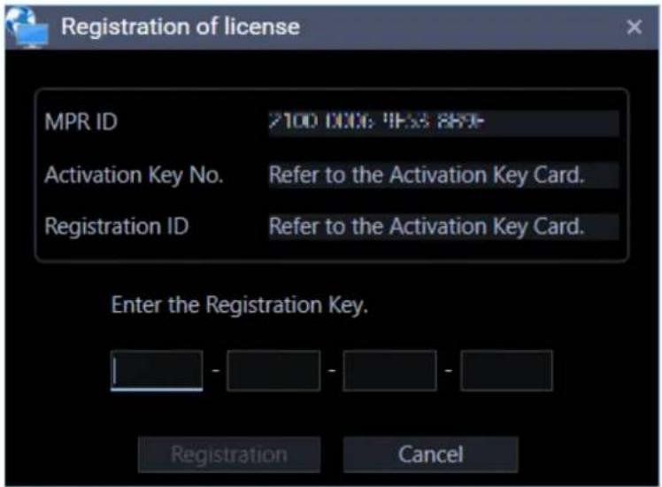
Enter the "Registration Key" obtained from the Key Management System.
Important:
- The Registration Key can be used only on a PC that displays MPR ID (used to obtain the key) on its screen.
- It cannot be used on other PCs.
Step 3
Click the [Registration] button.
→ The registration completion window will be displayed.

Important:
- It is impossible to register the "Registration Key" of the extension software (option).
- Be sure to perform the registration procedure on the PC in use.
Step 4
Click the [OK] button.

→ The license registration will be completed. The registration window for the administrator account will be displayed.
Refer to ☑ Registration of the administrator account when launching the first time.
2.3.1.2. Registration of the administrator account when launching the first time
If no administrator account is registered, register an account that has administrator authority.
Step 1
Enter a user name (administrator name) and a password, then click the [OK] button.
→ The registration completion window will be displayed.
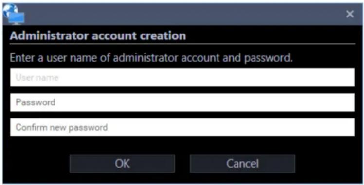
■ User name
Enter a user name to be registered for the administrator account.
Enter 4 - 32 alphanumeric characters for the administrator name.
Symbols and special characters cannot be used. The administrator name already in use cannot be used.
■ Password
Enter a password to be registered for the administrator account.
Enter 8 - 32 alphanumeric characters and special characters for the password.
The entered password will be displayed as "●".
Important:
- Set a password that includes three of the following four character types.
▶ Upper-case alphabet character, Lower-case alphabet character, Number, Special character (!#\$%')-=^\~¥|@`[]{}+*,<>/?_)
• "&: and a space is unavailable.
- A password consisting of the same character string as "user name" is unavailable.
■ Confirmation entry for password
Enter a password to be registered for the administrator account.
Check the typing error for password.
The entered password will be displayed as "●".
■ [OK] button
Click this button to apply and save the new password. (The window will close.)
The [OK] button cannot be clicked unless all entries are completed.
■ [Cancel] button
Click this button to cancel the entries. (The window will close.)
Step 2
Click the [OK] button.

→ The registration of the administrator account will be completed.
Login/Logout 2.3.2. 2.3.2.1. Log in
Step 1
Enter the registered "user name" and "password".

Important:
• It is recommended to change the password for the administrator periodically.
Note:
- It is possible to register a user as the auto login user when the same user name is used each time to log in to the software. Also, login by Single Sign-On function is available based on information of a Windows user who logged on to the domain in association with the Active Directory Server. The default setting of "User authentication" is "ON" (Not log in automatically). Change of the "User authentication" setting is made on the setup window by an administrator. • Refer to "Basic setup" for further information. • If Single Sign-On failed, the usual authentication window will be displayed after the error message.
Step 2
Click the [OK] button.
→ The operation window including the operation screen will be displayed.

Note:
- Unless otherwise mentioned, the screenshots of the operation window in this document are in the state that the license for the Extension Software WV-ASE202 is not being added.
- For the icon display of the tool bar of the operation window in case that the license of the Extension Software is added, refer to "Tool bar".
Validation period of password
An administrator can set the expiration date (31days/92days/184days) of the password.
When trying to log in after the set period passed, the message window saying "Please change the password." will be displayed.
Change the password by following the instructions displayed in the window.

■ Old password
Enter the current password. The entered password will be displayed as "●".
■ New password
Enter the new password. The entered password will be displayed as "●".
Enter 8 - 32 alphanumeric characters and special characters.
■ Enter the new password again to confirm.
Enter the new password. Check for typing errors in the password.
The entered password will be displayed as "●".
■ [OK] button
Change the password according to the entered content and return to the operation screen.
The [OK] button cannot be clicked unless all entries are completed.
■ [Cancel] button
Click this button to cancel the entries and return to the login window.
Important:
- Set the password using characters that follow the selected password policy. • "&:; and a space are unavailable. • A password consisting of the same character string as the "user name" is unavailable. • The same password as the old password cannot be set as a new password.
Note:
- It is impossible to log in using an expired password.
2.3.2.2. Change the password
Step 1
After entering "User name" and "Password" on the login window, check the "Change password" check box and click the [OK] button.
→ The "Change password" window will be displayed.
Step 2
Change the password by following the instructions displayed in the window.

■ Old password
Enter the current password. The entered password will be displayed as "●".
■ New password
Enter the new password. The entered password will be displayed as "●".
Enter 8 - 32 alphanumeric characters and special characters.
■ Enter the new password again to confirm.
Enter the new password. Check for typing errors in the password.
The entered password will be displayed as "●".
■ [OK] button
Change the password by following the entered content and shift to the operation screen.
The [OK] button cannot be clicked unless all entries are completed.
■ [Cancel] button
Click this button to cancel the password change and shift to the operation screen.
Important:
- Set the password using the characters following the selected password policy. • "&: and a space is unavailable.
- A password consisting of the same character string as "user name" is unavailable. • The same password as the old password cannot be set as a new password.
Step 3
Click the [OK] button.

→ The password change will be completed.
2.3.2.3. Log out (Switch to another user)
After logged out, by logging in using a different user name, it is possible to switch to another user.
Step 1
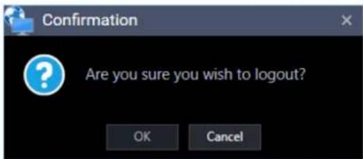
Select the "Logout" on the menu.

Step 2
Click the [OK] button.
Step 3
The login window will be displayed. To exit, click the [Cancel] button. To log in as another user, continue the operation by following the instructions below.
Enter the registered "user name" and "password".

Step 4
Click the [OK] button.
→ The operation window including the operation screen will be displayed.

2.3.3. Terminating this software
Step 1
Select "Exit" on the menu or click the [×] button at the top right of the operation window.
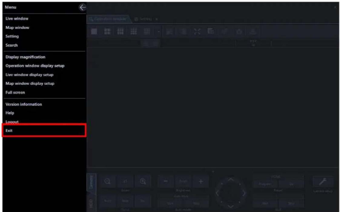
→ The completion window will be displayed.
Step 2
Click the [OK] button.
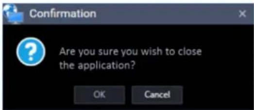
→ This software will be terminated.
2.4. Upgrading this software
Important:
- Check regularly the Panasonic support website and update to the latest version.
- When upgrading, contact the dealer and follow its instructions. • After upgrading, it is impossible to restore the previous version.
Step 1
Contact the dealer and download the latest installer of this software from the following URL.
URL: https://security.panasonic.com/download/
Step 2
Save the configuration data of this software to a folder following the procedure described in "Save the setup data as a backup".
Step 3
Uninstall this software following the procedure described in "Uninstallation".
Step 4
Double-click the downloaded "setup.exe" file. The installer of Video Surveillance Software will be launched. Install the software by following the instructions displayed on the monitor.
Step 5
Reboot the PC. When completing steps 1 - 3, reboot the PC to complete the installation.
2.5. ASM300 main screen description
The following are descriptions about the main screens of ASM300.

■ Title bar
Displays the shortcut icons of screens that can be displayed by the menu items and the tabs. Refer to "Title bar" for further information.
Tab
Displays the tabs of "operation window", "live window", "map window", "setup window" and "search window" to be used on this software.
Display order of the tabs can be changed and each tab can be opened separately from ASM300 as an independent window.
Refer to "Tab and Window" for further information.
Title bar 2.5.1.

The following are the descriptions of icons located from the left to the right.

The menu items are located on the menu bar. Refer to "Menu" for further information.

Displays the Live window. Refer to "Use the live window" for further information.
■ [Map window] icon
![PANASONIC WV-ASM300W - ■ [Map window] icon - 1](/content/2026/06/1353903/images/00d2efd377936789456a782dc12a9c7049dd038913e389e7530c3679826a427f.jpg)
Displays the Map window. Refer to "Use the map window" for further information.
■ [Setting] icon ( )
Displays the Setting window. Refer to "Setup Instructions" for further information.
■ [Search] icon ( )
Click this button to display the "Search" window. Refer to "Use the search window" for further information.
2.5.1.1. Menu

■ [Close] button ()
Closes the menu.
■ Live window
Displays the Live window. Refer to "Use the live window" for further information.
■ Map window
Displays the Map window. Refer to "Use the map window" for further information.
■ Setting
Displays the Setting window. Refer to "Setup Instructions" for further information.
■ Search
Click this button to display the "Search" window. Refer to "Use the search window" for further information.
■ Display magnification
Set the size of the operation window. Refer to "Set the display magnification" for further information.
■ Operation window display setup
It is possible to display/hide the function panel, operation panel, camera / time & date, sound collection position, cropping frame, face frame, and AVMD information display of the operation window.
Note:
- Face frame and AVMD information functions will become available after the license for the WV-ASE231 is added. • Face frame and AVMD information functions are supported by some models only. • Face frame and AVMD information will be displayed only when displaying images on a 1-screen.
- When "Frame display (only after determination)" is selected, the AVMD frame (red frame) will be displayed after the AVMD alarm is confirmed.
- When displaying images (MPEG-4) via ND300 or ND200, AVMD information will not be displayed. • i-VMD information of the camera will also be displayed.
- When displaying images via ND300, ND200, NV200, or NV300, i-VMD information will not be displayed.
- To display i-VMD information while displaying images via ND400, it is necessary to update the firmware of ND400 to V3.40 or later.
- The sound collection position will be displayed only when a network microphone is used. If this function is displayed, the sound collection position will also be displayed except when setting up the microphone. If this function is disabled, the sound collection position will be displayed only when setting up the microphone.
■ Live window display setup
It is possible to switch to display or hide the function panel of the operation window.
■ Map window display setup
It is possible to switch to display or hide the function panel of the map window.
■ Full screen
Display the image currently being displayed on a full screen.
Refer to "Monitor images on a full screen" for further information.
■ Version information
Displays the version information.
■ Help
Displays the operating instructions (help file).
- Logout
Enables logout, and displays the login window.
Refer to "Log out (Switch to another user)" for further information.
■ Exit
This software will be terminated.
Tab and Window 2.5.2.
Display order of the tabs of "live window", "map window", "search window" and "setup window" can be changed and each tab can be opened as an independent window.
2.5.2.1. Open the tab/Close the tab
■ Open the tab
To display "Live window", "map window", "setup window" and "search window" as a tab page, click a shortcut icon on the title bar or select a corresponding item from the menu. Refer to "Title bar" and "Menu" for further information.
■ Close the tab
A tab can be closed by clicking the [×] button next to a tab title.
2.5.2.2. Change display order of tabs
The display order of tabs on the window can be changed by dragging a tab onto the next tab. However, the "operation window" tab cannot be moved.
![graph TD A["Operation window"] --> B["Live window 1"] B --> C["Search"] C --> D["Settings"] E["Performance"] --> F["Timeline"] F --> G["Directory Service"] G --> H["Text display setting"] I["Basic setup"] --> J["Drawing setup"] J --> K["GUI display setup"] K --> L["Layout setup"] M["ENGLISH"] --> N[…](/content/2026/06/1353903/images/0ab7ef24c0c6655fa98ea4461386a1c1351409b1767f6368d3cdb2028f404bd0.jpg)
2.5.2.3. Separate a tab/Combine a tab with the window
- Separate a tab
It is possible to separate a tab from the window by dragging and moving the tab.
However, the "operation window" tab and the "setup window" cannot be separated from the window. The tabs can be set inseparable in the system setup. Refer to "Basic setup" for further information.


■ Combine a tab with the window
It is possible to combine a separated tab with the window by dragging the tab onto the window in which the tab was originally located.


Note:
- A state whether the tab is separated or combined will be held until the next time this software is launched.
Set the display magnification 2.5.3.
Set the display size of each window.
Step 1
Click the [Menu] icon on the title bar.
The menu will be displayed.

Step 2
Select the [Display magnification] from the menu.
The display magnification menu will be displayed.

Step 3
■ [Display magnification] menu
Adjust the display magnification by moving the slider. The display magnification ratio can be selected from 75%, 100%, 125%, 150%, 175%, or 200%.
+: Increases the display magnification. -: Reduces the display magnification. ←: Closes the "Display magnification" menu.

Note:
- The minimum size when "75%" is selected for "Display magnification" is 960×600. The minimum size when "100%" is selected for "Display magnification" is 1280×800. The minimum size when "125%" is selected for "Display magnification" is 1600×1000. The minimum size when "150%" is selected for "Display magnification" is 1920×1200. The minimum size when "175%" is selected for "Display magnification" is 2240×1400. The minimum size when "200%" is selected for "Display magnification" is 2560×1600. - "200%" is suited for a monitor screen resolution of 4K (3840×2160). When using a monitor whose resolution is less than 4K, it is recommended to set to "100%". Regardless of the selected ratio for the display magnification setting, a breakage of the screen layout may occur depending on the settings of Windows. Check if the settings of Windows are set as follows.
■ For Microsoft® Windows® 7
- Click [Control Panel] - [Appearance and Personalization] - [Display] in order.
- Select "Smaller-100%" in the [Make it Easier to read what's on your screen] section.
- Click the [Apply] button.
- Restart the PC, or log in again after logging off once.
■ For Microsoft® Windows® 8.1
- Click [Control Panel] - [Appearance and Personalization] - [Display] in order.
- Check the check box of [Let me choose one scaling level for all my displays].
- Select "Smaller - 100%" in the [Change the size of all items] section.
- Click the [Apply] button.
- Restart the PC or sign in once after signing out.
■ For Microsoft® Windows® 10
- Click [Settings] - [System] - [Display].
- Set [Change the size of text, apps, and other items] to [100%].
- Click the [Apply] button.
- Restart the PC or sign in once after signing out.
- The face matching monitor (available when the license for WV-ASE231 is applied), the heat map window (available when the extension option for image analysis is applied), the standard format conversion window, the visibility enhancement control (available when the license for WV-ASE205 is applied), the text information window, and the viewer software are not applicable.
- This function is not applicable to the title bar at the top of the window, software name, minimize and maximize buttons, exit button, message windows, and other Windows-specific windows.
- The thickness of the borders of the image selection frame border, screen parting border, AVMD/i-VMD information, face frame, sound collection position, cropping frame, drag & zoom frame, and VMD search frame may vary depending on the display magnification.
- Depending on display magnification, some Windows desktop items (display magnification is 100%) may look different from the screen when displaying with "Normal". However, there is no difference in functions.
Operation window description 2.6.
The following are descriptions about each item displayed on the operation window.
Note:
- The operation window display size can be changed between the range of 960×600 (smallest) and 3840×3840 (largest) with the mouse operation. Refer to "Set the display magnification" for further information.
The minimum size in case when "75%" is selected for "Display magnification" is 960×600.
The minimum size in case when "100%" is selected for "Display magnification" is 1280×800.
The minimum size in case when "125%" is selected for "Display magnification" is 1600×1000.
The minimum size in case when "150%" is selected for "Display magnification" is 1920×1200.
The minimum size in case when "175%" is selected for "Display magnification" is 2240×1400.
The minimum size in case when "200%" is selected for "Display magnification" is 2560×1600.
- The function panel and the image display area will become smaller/larger in accordance with the change of the operation window display size. • Image distortion may occur during the change of the operation window display size.

■ Tool bar
Displays the shortcut icons of each function.
Refer to "Tool bar" for further information.
■ Status bar
Displays a display status of images currently being displayed, playback speed, recorder name (encoder name), camera name, a status of recorder, status of alarm/error occurrence, presence or absence of SD memory data, and time and date.
Refer to "Status bar" for further information.
■ Function panel
The function panel is provided on the left of the operation window. When the desired function bar on the function panel is clicked, the respective function panel will be displayed.
Refer to "Function panel" for further information.
■ Image display area
Displays images on 1-/2A-/2B-/3A-/3B-/3C-/4-/4A-/4B-/4C-/4D-/4E-/5-/6-/6A-/7-/7A-/9-/10-/13-/16-/25-/36-/49-/64-screen. (25-/36-/49-/64-screen will become available by adding licenses of WV-ASE202. The screen type can be changed simply by clicking the buttons displayed on "Tool bar".)
When right-clicking on this area, the pop-up menu will be displayed. However, each function can be selected only when displaying images on 1-screen.
Refer to "Pop-up menu" for further information.
The descriptions of the alarm/error will be displayed in a pop-up window (notification window) on the operation window upon an alarm/error occurrence.
Refer to "Alarm/event notification message" for further information.
■ Information display area
Displays recording status of images, camera title, and time & date.
Refer to "Information display area" for further information.
■ Operation panel
The cameras and recorders are operable with this panel. Refer to "Operation panel" for further information.
Tool bar 2.6.1.

The following are the descriptions of icons located from the left to the right.
■ [Screen layout] icon
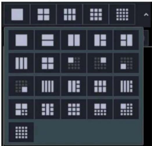
Selectable from the pull-down menu and the image display area can be changed.
Refer to "Switch the pattern of the screen" for further information.
An icon to be displayed at the top line of the pull-down menu can be set on the setup window.
Refer to "Layout setup" for further information.

It may be displayed depending on the state of the shortcut icon.
An icon will slide to the left by clicking 📄. An icon will slide to the right by clicking 📄.
■ [5 Cropping] icon ( )
Click this icon to display the image display area with 5 cropping areas.
Note:
• The available screen pattern is 1-screen. - This function is available only with the cameras (=> Use cropping function) activating the cropping function. - It is impossible to select [5 Cropping] icon only from the system controller WV-CU950.
■ [1 Cropping] icon ( )
Click this icon to display the image display area with 1 cropping areas.
Note:
• The available screen pattern is 1-screen. - This function is available only with the cameras (Use cropping function) activating the cropping function. - It is impossible to select [1 Cropping] icon only from the system controller WV-CU950.
■ [Full screen] icon ( )
Display the image currently being displayed on a full screen.
Refer to "Monitor images on a full screen" for further information.
■ [Image Enhancement] icon (Available after the license for the WV-ASE205 is added) ( )
The image enhancement window will be displayed.
Refer to "Use the visibility enhancement function" for further information.
■ [Face search] icon (Available after the license for the WV-ASE231 is added) (
Click this icon to launch the face search monitor.
Refer to "Use the face search monitor" for further information.
■ [Heat map] icon (Available after the optional extension for Video Analytics is registered) ( ) Launch the Map window.
Refer to "Use the heat map display function" for further information.
■ [File conversion] icon (
The screen to be used to convert n3r files to playable files on the media player, etc. will be displayed. Refer to "Convert a file to the standard format" for further information.
■ [Fisheye Control] icon (
When displaying fisheye images in the single PTZ or quad PTZ format, a number icon appears on the fisheye control screen to indicate the position where images are being displayed on the operation window. Refer to "Use the fisheye control" for further information.
Note:
- This is applied only to images on 1-screen, 2A-screen, 2B-screen, 4-screen, on left area of 3A-screen, on right area of 3B-screen, and on large areas of 7-/10-/13-screen.
- When [Fisheye] is selected for [Fisheye display menu], it is impossible to select [Fisheye Control]. • This function is available only for cameras that support the fisheye image display change function.
- Depending on the position of the number icon of [Fisheye Control], it may not be located at the center of displayed images.
- It is impossible to select [Fisheye Control] only from the system controller WV-CU950.
■ [Decoder control] icon (
Click this icon to display the "Decoder control" window.
Refer to the descriptions about the "Control a decoder" for further information.
■ [Save a still picture] icon (
Select this to save the image currently being displayed as a JPEG or BMP file. Refer to "Save a still picture" for further information.
■ [Print] icon ( )
Select this to print the image currently being displayed. Refer to "→ Print" for further information.
Status bar 2.6.2.

Important:
- Check if the model in use is compatible with each function.
■ Recorder title/camera title
Source (recorder (encoder) title and the camera title) of the image currently being displayed will be displayed in this area.
■ [ALM] button
Indicates that an emergency recording is being performed or an event occurred. When the button is clicked, the alarm action will be cancelled.
Note:
• In case of ND300 (Version 4.69 or earlier) or HD300, the error action also will be cancelled. - In case of ND300 or HD300, nothing will change even when an emergency recording is being performed. • This button will not be displayed when using Video Insight Server.
■ [ERR] button
Indicates that an error occurred. When the button is clicked, the error action will be cancelled.
Note:
• In case of ND300 (Version 4.69 or earlier) or HD300, the alarm action also will be cancelled. - In case of HD300, the error action will not be cancelled even when the button is clicked. In this case, refer to the operating instructions of the recorder in use for how to cancel an error action.
■ [SD] button (Button to obtain the SD memory data)
Indicates that the SD memory card in the camera connected to the recorder contains recorded images. When the button is clicked, the recorded images on the SD memory card will be transferred to the recorder.
Important:
- When the recording rate for the SD memory recording is not set, the SD memory data obtain button will not be displayed. Refer to the operating instructions of the recorder in use for how to set the recording rate for the SD memory recording.
- When using NX-series recorder or the recorder that does not support obtain of SD memory data manually, the SD memory data obtain button will not be displayed.
- The SD memory data cannot be obtained during the emergency recording. Refer to the operating instructions of the recorder in use for further information about the emergency recording.
- Depending on the recorder in use, all login users will be forcibly logged out when obtainment of the SD memory data starts. In addition, all cameras currently being performed will stop.
Note:
- The [SD memory data acquisition (letters "SD" in blue)] button will be displayed when there is no recorded image in the SD memory card.
- When the [SD memory data acquisition (letters "SD" in blue)] button is clicked, checking if there is recorded image in the SD memory card or not will start. When there is, the letters "SD" will change to red. Images saved on the SD memory card will be transmitted to the recorder depending on the model of the recorder in use.
- When the [SD memory data acquisition (letters "SD" in red)] button is clicked, recorded images on the SD memory card will be transferred to the recorder.
■ [Mic input] button
Click this button to turn on/off the audio reception (from camera to PC). When this button is clicked, the button will turn into 📄 and audio from the camera will not be heard.
Note:
- When right-clicked on the button, a pop-up menu will be displayed. Volume of audio reception can be adjusted by selecting Strong/Middle/Weak from this pop-up menu.
- When displaying images on a multi-screen, audio will be output from the camera which is the source of images displayed in the upper-left area of the multi-screen. When another area is selected, audio associated with images displayed in the upper-left area of the multi-screen will still be heard, though this button will disappear.
- When audio is being transmitted to the same camera by another user, this button will turn to 📄 and become invalid. In addition, audio from cameras will not be heard for some cameras. • This button will not be displayed when using Video Insight Server.
■ [Audio output] button
Click this button to turn on/off the audio transmission (from PC to camera). When this button is clicked, the button will turn to 📄 and audio from the PC will not be sent.
Note:
• Volume level of audio transmission cannot be changed. (Depending on the camera in use, volume level of audio transmission can be adjusted by configuring the settings of the camera.) - When displaying images on a multi-screen, audio will be transmitted to the camera which is the source of images displayed in the upper-left area of the multi-screen. When another area is selected, audio will still be transmitted to the camera which is the source of images displayed in the upper-left area, though this button will disappear. - When audio is being transmitted to the same camera by another user, this button will turn to 📄 and become invalid. In addition, the audio from the PC will not be sent. - It is possible to transmit audio up to 5 minutes per transmission. When 5 minutes elapsed, the audio reception will be turned on automatically. To transmit audio again, click the [Audio transmission] button. - In the case of a camera that receives images via the recorder, there is no sending function, so the [Audio output] button is not displayed.
■ [LIVE]/[PLAY]/[SD PLAY]
Indicates the type (live/playback/SD memory data playback) of the images currently being displayed.
■ [Step 1] - [Step 7]
Indicates the playback speed. Values in the brackets () is in the high-speed playback smooth mode.
[Step 1]: Normal playback speed
[Step 2]: Approx.4x playback speed (Approx.2x playback speed)
[Step 3]: Approx.8x playback speed (Approx.4x playback speed)
[Step 4]: Approx.16x playback speed (Approx.8x playback speed)
[Step 5]: Approx.32x playback speed (Approx.16x playback speed)
[Step 6]: Approx. 48x playback speed (Approx. 32x playback speed)
[Step 7]: Approx. 96x playback speed (Approx. 64x playback speed)
Note:
- Video Insight Server plays recorded images in the high-speed playback smooth mode. The maximum playback speed using Video Insight Server is [Step 5].
- When the image capture size and the frame rate of the recorded image are high, when the processing load is too heavy on the recorder or on the PC, or when the network traffic is heavy, the playback speed of the high-speed playback may become lower than the described value.
■ REC lamp
This indicator will light red when the recording of the images currently selected is being performed.
Note:
This button will not be displayed when using Video Insight Server.
■ [COPY]/[DELETE]
[COPY]: Indicates that copying of image data is being performed. [DELETE]: Indicates that deletion of image data is being performed.
■ Time & date
When displaying live images, the time & date of the selected device will be displayed. (For some devices, Time & date will not be displayed when displaying images from camera that is not registered in the recorder or when images are directly being received.) When displaying recorded images, the recording time & date will be displayed. In case of 24h display, [AM]/[PM] will not be displayed.
The time & date will be followed by an asterisk "*" when the daylight saving time is applied.
Function panel 2.6.3.
Operations such as live view, playback, search, download, alarm, and error information can be performed using the function panels on the left side of the operation window.
Each panel can be opened or closed by clicking its title bar. However, it is not possible to open two or more panels simultaneously.

Note:
- Refer to the following for descriptions of how to operate each function panel. Name search: "Search for registered device name, folder name, group name, and sequence name" Device tree panel: "Confirm the registered devices" Group panel: "Display images from the cameras registered as a group (group display)"
Sequence panel: "Switch groups automatically and display images from each group sequentially (sequence)"
Quick playback panel: "Play images using the 'Quick playback' panel"
Search panel: "Play recorded images using the 'Search' panel"
Download panel: "Download recorded images"
Alarm log panel: "Alarm log panel"
Device error log panel: "Device error log panel"
Network error log panel: "Network error log panel"
- As for the device tree panel, in the case of HD300 and HD600, all channels of the camera will be displayed in the tree regardless of the camera connection status.
- The device tree display can be changed to display sorted by group in each folder. The device tree on the search panel and the download panel will also change in the same manner. However, in the case of the search panel and the download panel, only cameras registered in the recorder will be displayed.
Refer to "Drawing and audio setup" for the setting to sort by group in each folder.
- When "ON" is selected for "Display the panel open/close button", the panel open/close button will be displayed at the side of the menu panel. Displaying/hiding of the menu panel can be operated by clicking the icon [Δ] on the panel open/close button.
Refer to "Display/Hide the function panel and the operation panel" for further information.
Refer to the "GUI display setup" for information about "Display the panel open/close button".
Pop-up menu 2.6.4.
When right-clicking on the image display area, the pop-up menu will be displayed.
* 1 Selecting is available only when displaying images on a 1-screen.

■ Save a still picture*
If the license of WV-ASE231 is not registered, select this to save the currently displayed image as a JPEG file.
If the license of WV-ASE231 is registered, select this to save the currently displayed image as a BMP file. Resolution of images to be saved can be changed on the setup window. Refer to "Drawing and audio setup" for further information.
Note:
- "Save a still picture" on the pop-up menu will not be displayed when the user is restricted by the user level determined by the administrator to save an image as a still picture.
■ Print*
Select this to print the image currently being displayed.
Note:
- "Print" on the pop-up menu will not be displayed when the user is restricted by the user level determined by the administrator to print images.
■ Register this face (Available after the license for the WV-ASE231 is added)
It is possible to newly/additionally register face thumbnail images from playback images on the recorder. Refer to "Register from recorded images" and "Additionally register from recorded images" for further information.
■ Set to Face Search 1/Set to Face Search 2 (Available after the license for the WV-ASE231 is added.)
Playback images from the recorder can be set to "Faces" of "Face search". Refer to "Search face" for further information.
EL-zoom*
Select this to enlarge the image currently being displayed. Zoom factor can be selected from "x1", "x2", "x4", and "x8".

Note:
- A black screen may sometimes be displayed when keeping on clicking around the edge of the screen to enlarge MPEG-4, H.264 or H.265 images using the EL-zoom function. • The [EL-zoom] button will not be displayed during playback of recorded images. • The [EL-zoom] button will not be displayed when using Video Insight Server.
- For the cameras that can use this function, refer to "Camera image zoom operation".
Stream
Either of streams of live images or playback images in the selected area can be selected. It can be selected from Stream 1/Stream 2/Stream 3/Stream 4/Reset to the previous setup.
Stream 1: Selects "Stream1"
Stream 2: Selects "Stream2"
Stream 3: Selects "Stream3" (Not be displayed in case of a recorder or a camera with 2 streams)
Stream 4: Selects "Stream4" (Not be displayed in case of a recorder or a camera with 2 streams)
Return to the previous setup: Returns to the stream previously set in "Device setup" on the setup window.

Note:
- Selection of live image stream is available only when directly receiving from a camera. When live images are being obtained via a recorder, it is impossible to select for "Stream".
- Playback stream of images recorded in a recorder can be selected only when NX-series is in use. When a recorder other than NX-series is being used, it is impossible to select for "Stream". • If failed to receive the selected stream images, a black screen will be displayed.
- After changing the display stream in [Stream], if you perform the following operation, the changed stream will return to the previous setting. • Clear the currently displayed image
- Change display camera
- Change image display area
- Stop during recording playback
- A change of stream by "Stream" is temporary and will not be saved.
Configure the setting of stream on the setup window.
■ Download*
The download panel will open and display information (recorder/camera/time & date) of the recorded image currently being played.
Refer to "Use the download function" for further information.
Note:
- "Download" on the pop-up menu will not be displayed when the user is restricted by the user level determined by the administrator to download recorded images.
- When displaying live images, it is impossible to select "Download" on the pop-up menu.
■ Quick download
Download of images currently being played in the selected area will start.
Refer to "Use the quick download" for further information.
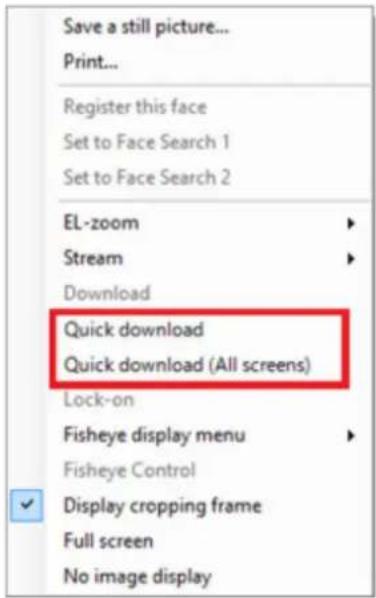
Note:
- "Quick download" on the pop-up menu will not be displayed when the user is restricted by the user level determined by the administrator to download recorded images.
- When displaying live images, it is impossible to select "Quick download" on the pop-up menu.
- The downloaded file will be saved on the desktop.
■ Quick download (All screens)
Download of images currently being played in all areas will start. Refer to "Use the quick download" for further information.
Note:
- "Quick download (All screens)" on the pop-up menu will not be displayed when the user is restricted by the user level determined by the administrator to download recorded images.
- When displaying live images, it is impossible to select "Quick download (All screens)" on the pop-up menu.
- The downloaded file will be saved on the desktop.
■ Lock-on*
Select this to start auto track for the object on the clicked point only when "Camera" is selected for "Live image source". Depending on the target object or surrounding environment, this function may not work correctly.
Note:
- This function is available only when the camera in use is WV-SC386, WV-SW396/WV-SW396A, WV-SC588/WV-SC588A, WV-SW598/WV-SW598A, WV-SW397/WV-SW397A/WV-SW397B, WV-SC387/WV-SC387A, WV-X6533LN or WV-S6532LN.
- This function is disabled when WV-X6533LN/WV-S6532LN is set into the "Insert/Remove SD memory card" mode.
■ Fisheye display menu
Change the display format of fisheye images.
The display format is selectable from Fisheye, Single PTZ, Quad PTZ, Panorama and Double Panorama.

Note:
- This is applied only to images on 1-screen, 2A-screen, 2B-screen, 4-screen, on left area of 3A-screen, on right area of 3B-screen, and on large areas of 7-/10-/13-screen.
- This function is available only for live images or recorder playback images. SD playback images are not supported. • This function is available only for cameras that support the fisheye image display change function.
- It is impossible to select [Fisheye display menu] only from the system controller WV-CU950.
■ Fisheye Control
When displaying fisheye images in the single PTZ or quad PTZ format, a number icon appears on the fisheye control screen to indicate the position where images are being displayed on the operation window.
Note:
- This is applied only to images on 1-screen, 2A-screen, 2B-screen, 4-screen, on left area of 3A-screen, on right area of 3B-screen, and on large areas of 7-/10-/13-screen.
- When [Fisheye] is selected for [Fisheye display menu], it is impossible to select [Fisheye Control]. • This function is available only for cameras that support the fisheye image display change function.
- Depending on the position of the number icon of [Fisheye Control], it may not be located at the center of displayed images.
- It is impossible to select [Fisheye Control] only from the system controller WV-CU950.
- When "Recorder" is selected for "Live image source" of a fisheye camera registered in the recorder, images from the preset position of a camera in the default state will be displayed.
- When "Single PTZ" or "Quad PTZ" is selected for "Fisheye display menu", "Auto pan", "Preset sequence" and "Preset position registration" will not be supported. As for recorded images, "Brightness" will not be supported.
- It is impossible to select [Fisheye display menu] only from the system controller WV-CU950.
■ Display cropping frame
Determine whether or not to display the cropping frame.
■ Full screen
Display the image currently being displayed on a full screen.
Refer to "Monitor images on a full screen" for further information.
■ Image rotation
Adjust the display position when displaying fisheye images in the panorama or double panorama format.
- 30° clockwise: Rotates the display position 30° clockwise. • 1° clockwise: Rotates the display position 1° clockwise. • 30° counterclockwise: Rotates the display position 30° counterclockwise. • 1° counterclockwise: Rotates the display position 1° counterclockwise.
- Reset to the initial value: Reset the initial display position to the previous position before rotation.
- 0° (Off): The image will not be rotated.
- 180° (Upside down): The image will be flipped upside down.
Note:
- This item is selectable only when a fisheye image is displayed in the panorama format or the double panorama format. In other cases, this item will not be displayed.
■ No image display
Clear the currently displayed image.
Information display area 2.6.5.
Information of the images currently displayed, such as time & date, camera title and the recording status, will be displayed in this area.
camera1
Jun/21/2011 04:19:19 PM
■ REC indicator/Mark of recorder in communication
This indicator will light when a recording of images is being performed.
Note:
• It may take time to play depending on the operating environment of the recorder. - Turn the disks other than the disk currently being accessed and its peripheral disks to the stand-by control mode (hibernation) to achieve life prolongation of the disks of NX400 (version 2.0 or later) and NX300. (Refer to the operating instructions of the recorder for further information about the HDD stand-by control mode.) When the inactive disk is accessed at the time of playback of recorded images, the mark 📁 indicating that the recorder is in communication will be displayed in the information display section instead of the REC indicator until the disk responds.
■ Camera name
Indicates the camera name.
■ Time & date
Time and date of images will be displayed. For some devices, time & date will not be displayed when displaying images from a camera that is not registered in the recorder or when images are directly being received.
Operation panel 2.6.6. 2.6.6.1. Camera operation panel

Important:
- Check if the model in use is compatible with each function. • To operate the newly registered camera, restart this software before starting operation.
Note:
• Operation of the camera operation panel works only for the camera respective the selected image. - The camera operation panel will not be displayed when the user is restricted by the user level determined by the administrator to operate the cameras.
■ Zoom
Zooming can be adjusted by clicking the [-] (wide) button or the [+] (tele) button.
When clicking the [x1] button, the zoom ratio will be reset.
Note:
- Zooming is available operating the mouse wheel on the camera image.
- For the cameras that can use this function, refer to "Camera image zoom operation".
■ Focus
When the [Auto] button (auto focus) is clicked, the focus will automatically be adjusted.
Focusing can be manually adjusted by clicking the [Near] button or the [Far] button.
■ Auto mode
Select the auto function from the following.
• Auto track: The camera automatically tracks motion of the subject displayed in the image display area. • The camera automatically moves from the start point to the end point set in advance. - Preset sequence: The camera automatically moves to the preset positions in numerical order of the preset position numbers. - Sort: The camera automatically moves to the closest preset position from the current position. - Patrol1 - Patrol4: Manual operation of the camera that recorded in advance will automatically be executed.
Clicking the [Start] button performs restart.
Clicking the [Exit] button performs restart.
Note:
- "Auto mode" are available only when the camera in use has these functions. Refer to the operating instructions of the camera in use for further information about the auto function of the camera. When executing the auto mode with a fisheye camera on which "Quad PTZ" is selected for the image capture mode, images displayed in the upper left area of 4-screen will be operated.
- This function is disabled when WV-X6533LN/WV-S6532LN is set into the "Insert/Remove SD memory card" mode.
- When performing the auto mode while "Cropping" is selected for the image capture mode of 7-series cameras, only CH1 among CH1 - CH4 will work.
- When acquiring images from the recorder, the operation of patrol differs depending on the recorder model. When using the network recorder, only patrol 1 works.
■ Control pad
Clicking the buttons around the control pad can move (pan/tilt) a camera in the clicked direction. Clicking inside the control pad also can adjust the vertical/horizontal position (pan/tilt) of the displayed live images. Panning/tilting speed will be faster if a clicked point gets farther from the center point of the control pad.
Note:
- Panning and tilting are available only when the camera in use is a PTZ camera.
- For the cameras that can use this function, refer to "Camera image pan/tilt operation".
■ Brightness
By clicking the [-] (darker) button or the [+] (brighter) button to adjust the lens iris. It is possible to reset the set brightness by clicking the [Standard] button.
■ Preset
Select a preset number from the following.
Default: HOME/1 - 256
When the [Move] button is clicked, the camera will move to the selected preset position.
When the [Registration] button is clicked, the current position will be registered as the preset position of the selected preset position number.
Note:
- Preset position function is available only when the camera in use is a PTZ camera.
- Registration is unavailable when [HOME] is selected.
- It is possible to register the preset position only when the user is not restricted by the user level determined by the administrator to operate the cameras.
- Refer to the operating instructions of the recorder and the camera in use for further information about the available preset position numbers.
- When executing the preset registration using a fisheye camera with the image capture size of "Quad PTZ", different action may be taken depending on the model of camera. Refer to the operating instructions of the devices for further information. When a 3M fisheye camera is used, the position of the camera from which images are displayed on the upper left screen of 4-screen will be registered. When a 5M fisheye camera or 9M fisheye camera is used, all of positions of the cameras from which images are displayed on 4-screen will be registered. The preset numbers will be handled in increments of 4. (Example) When an action is registered in preset number 2 (same action for preset number 1, 3 and 4), the action will be registered as the preset action of 1-4 (in order from the upper left screen).
- When performing the preset registration while "Cropping" is selected for the image capture mode of 7-series cameras, the position displayed on CH1 will be registered regardless of the currently displayed channel (among CH1 - CH4). Display images on CH1 when performing the preset registration.
- The preset position name (Preset No.) can be changed to a desired one. For details, refer to "Set
the preset position name".
■ AUX
Select an AUX connector from the following.
Default: 1/2/3
When the [Open] button is clicked, the selected AUX connector will be opened.
When the [Close] button is clicked, the selected AUX connector will be closed.
Note:
- AUX terminal name (Terminal No.) can be changed to a desired one. For details, refer to "Set the AUX terminal name".
■ Camera setup
Moves to the panel on which each setting of camera can be configured. Refer to "Camera setup panel" for further information.
■ Mic setup
Moves to the panel on which each setting of microphone can be configured. Refer to "Mic setup panel" for further information.
Note:
• This button will be displayed when a linked camera is in use.
2.6.6.2. Playback operation panel

Important:
- Check if the model in use is compatible with each function.
Note:
- The playback operation panel will not be displayed when the user is restricted by the user level determined by the administrator to play recorded images.
- The playback operation panel will not be displayed when displaying images from a camera that is not registered in the recorder.
- When displaying images on a multi-screen, images displayed in all areas of a multi-screen will be controlled simultaneously using the playback operation panel.
■ [PREV RECORD] button
Playback will start after skipping to the previous recorded image.
Note:
• This function is not supported by Video Insight Server.
■ [REW] button
Playback speed for fast reverse playback will be changed in the following order each time this button is clicked: Step 2 (Approx. 4x) → Step 3 (Approx. 8x) → Step 4 (Approx. 16x) → Step 5 (Approx. 32x) → Step 6 (Approx. 48x) → Step 7 (Approx. 96x)
Note:
- When fast reverse playback is performed while playing images on HD600, the step of playback speed above will start from "Step1 (1x)".
- When the image capture size and the frame rate of the recorded image are high, when the processing load is too heavy on the recorder or on the PC, or when the network traffic is heavy, the playback speed of the fast reverse playback may become lower than the described value.
■ [REV PLAY] button
Reverse playback of a recorded image will be performed. When this button is clicked during fast playback or fast reverse playback, reverse playback at normal speed will start.
Note:
- When playing MPEG-4, H.264 or H.265 images, some frames of recorded images may not be displayed. Reverse playback will be performed with the set refresh interval of the camera.
■ [PLAY] button
Playback of a recorded image will be performed. When this button is clicked during fast playback or fast reverse playback, playback at normal speed will start.
■ [FF] button
Playback speed will be changed in the following order each time this button is clicked: Step 2 (Approx. 4x) → Step 3 (Approx. 8x) → Step 4 (Approx. 16x) → Step 5 (Approx. 32x) → Step 6 (Approx. 48x) → Step 7 (Approx. 96x)
Note:
- In the high-speed playback smooth mode, playback speed will be changed in the following order: Step 2 (Approx. 2x) → Step 3 (Approx. 4x) → Step 4 (Approx. 8x) → Step 5 (Approx. 16x) → Step 6 (Approx. 32x) → Step 7 (Approx. 64x)
- The high-speed playback smooth mode is available only when NX-series and the firmware of the ND400 is Version 2.5 or later. When the firmware of ND400 is use is 2.3 or earlier, or another recorder is used, frames will be skipped even in the high-speed playback smooth mode.
- When using Video Insight Server, the maximum playback speed is [Step 5].
- When the image capture size and the frame rate of the recorded image are high, when the processing load is too heavy on the recorder or on the PC, or when the network traffic is heavy, the playback speed of the high-speed playback may become lower than the described value.
■ [NEXT RECORD] button
Playback will start after skipping to the next recorded image.
When there is no next/previous recorded image to be skipped to, the current playback will continue.
Note:
• This function is not supported by Video Insight Server.
■ [REV SKIP] button
Playback will start after skipping to the point of the set amount of time backward.
Note:
- This button will not work when the playback point is at the start point or the end point of the recorded images.
- When clicking this button while playing MPEG-4, H.264 or H.265 images, a skipped point may be a few seconds later from a point to be skipped with the selected amount of time.
■ [PREV IMAGE] button
The previous frame will be displayed when this button is clicked during pausing.
Note:
- When playing MPEG-4, H.264 or H.265 images, some frames of recorded images may not be displayed. Reverse frame by frame playback will be performed with the set refresh interval of the camera.
■ [PAUSE] button
Playback will stop when this button is clicked during playback. Playback will resume when this button is clicked during pausing.
■ [STOP] button
Playback will stop and live images will be displayed.
■ [NEXT IMAGE] button
The next frame will be displayed when this button is clicked during pausing.
■ [SKIP] button
Playback will start after skipping to the point of the set amount of time.
Note:
- This button will not work when the playback point is at the start point or the end point of the recorded images.
- When clicking this button while playing MPEG-4, H.264 or H.265 images, a skipped point may be a few seconds later from a point to be skipped with the selected amount of time.
■ SKIP TIME
Select an amount of time to skip from the following.
Click the [-] button or the [+] button while displaying playback recorded images on the WJ-HD300 on a
1-screen to adjust the image refresh intervals of playback images. When the [-] button is clicked, the image refresh intervals will become longer. When the [+] button is clicked, the image refresh intervals will become shorter.
When playing recorded images on a 1-screen, text information can be added. The "Edit text" window will be displayed when this button is clicked during pausing playback.
When playing recorded images on a 1-screen, text information can be added. The "Edit text" window will be displayed when this button is clicked during pausing playback.
Note:
• This function is available only when the recorder in use is HD300, ND300 or ND200.
■ [REC START]/[REC STOP] button
Manual recording will start or stop.
Note:
• This function is not supported by NV200, NV300 and NX-series.
■ [Mic setup] button
Moves to the panel on which each setting of microphone can be configured. Refer to "Mic setup panel" for further information.
Note:
• This button will be displayed when a linked camera is in use.
2.6.6.3. Timeline playback operation panel
Important:
• The timeline function is not available on HD300 and the cameras not registered in the recorder.
Note:
- The timeline playback operation panel will be displayed when "ON" is selected for "Timeline display" on the setup window. Refer to "→ Timeline" for further information.
- Timeline will not be displayed if it is out of the period specified on "Number of acquired days" on the setup window.
- Make sure that "Master" is set for "Timeline DB" on the setup window on the PC in use. When "Slave" is set for "Timeline DB", make sure that an address is specified in "Master Address".
- The timeline playback operation panel will not be displayed when the user is restricted by the user level determined by the administrator to play recorded images.
- Images from cameras for which the timeline can be displayed are up to 16 areas on the upper left side of the multi-screen.
- On the timeline playback operation panel, the speed buttons (− and +) and the TEXT button will not be displayed. When operation of the buttons above is needed, select "OFF" for "Timeline display" on the setup window first and then operate the playback operation panel again. • Face matching alarm can be displayed on the timeline of only the PC that has received the alarm.
- Depending on the status of the recorder, the timeline may have cut line even the recorded images exist. The timeline bar is just an indication and is not completely in accord with the recorded images. • The display interval of the timeline may be different depending on the model of the recorder.

■ Time & date
Time and date indicated by timeline will be displayed. The calendar will be displayed by clicking When time and date are selected, timeline of the designated time and date will be displayed.

■ Change time axis button (◀) (▶)
Timeline of the past will be displayed by clicking
<. Timeline of the future will be displayed by clicking >
■ Change time axis scale slider
Perform enlargement display or reduction display of the time axis by operating position of the slider. When the slider is moved to the [+] direction, the time axis display will be enlarged in order. When the slider is moved to the [-] direction, the time axis display will be reduced in order.
■ [24H] button
By clicking this button, the time axis will be displayed in 24-hour format.
■ Timeline bar
Camera title and recording/event information of the camera from which images are currently being displayed will be displayed. When double-clicked on the designated timeline, playback will start from the clicked point. Color coding of the timeline bar is as follows:
 | Site alarm |
 | Terminal alarm, command alarm, VMD, video loss, emergency |
 | Manual recording |
 | Schedule recording |
 | Face matching alarm, Unregistered face detection alarm |
| No color No recording/event data | |
Note:
• VMD event of V-series camera will not be displayed.
■ Timeline display change button (☐) (☐)
By clicking ↗ or ↘, it is possible to change the camera for which timeline is to be displayed.
■ Timeline seek bar
By operating the seek bar, it is possible to start playback from a desired time. The seek bar will automatically be updated during playback according to the status.
■ REV PLAY button

Reverse playback of a recorded image will be performed. When this button is clicked during fast playback or fast reverse playback, reverse playback at normal speed will start.
Note:
- When playing MPEG-4, H.264 or H.265 images, some frames of recorded images may not be displayed. Reverse playback will be performed with the set refresh interval of the camera.
■ STOP button (

Playback will stop and live images will be displayed.
■ PLAY button (

Starts playback from the point designated by the timeline seek bar.
■ PREV RECORD button (

Playback will start after skipping to the previous recorded image.
■ REW button

Playback speed for fast reverse playback will be changed in the following order each time this button is clicked: Step 2 (Approx. 4x) → Step 3 (Approx. 8x) → Step 4 (Approx. 16x) → Step 5 (Approx. 32x) → Step 6 (Approx. 48x) → Step 7 (Approx. 96x)
Note:
- When fast reverse playback is performed while playing images on HD600, the step of playback speed above will start from "Step1 (1x)".
- When the image capture size and the frame rate of the recorded image are high, when the processing load is too heavy on the recorder or on the PC, or when the network traffic is heavy, the playback speed of the fast reverse playback may become lower than the described value.
■ FF button (

Playback speed will be changed in the following order each time this button is clicked: Step 2 (Approx. 4x) → Step 3 (Approx. 8x) → Step 4 (Approx. 16x) → Step 5 (Approx. 32x) → Step 6 (Approx. 48x) → Step 7 (Approx. 96x)
Note:
- In the high-speed playback smooth mode, playback speed will be changed in the following order: Step 2 (Approx. 2x) → Step 3 (Approx. 4x) → Step 4 (Approx. 8x) → Step 5 (Approx. 16x) → Step 6 (Approx. 32x) → Step 7 (Approx. 64x)
- The high-speed playback smooth mode is available only when NX-series and the firmware of the ND400 is Version 2.5 or later. When the firmware of ND400 is use is 2.3 or earlier, or another recorder is used, frames will be skipped even in the high-speed playback smooth mode.
- When the image capture size and the frame rate of the recorded image are high, when the processing load is too heavy on the recorder or on the PC, or when the network traffic is heavy, the playback speed of the high-speed playback may become lower than the described value.
■ NEXT RECORD button ( )
Playback will start after skipping to the next recorded image. When there is no next/previous recorded image to be skipped to, the current playback will continue.
■ PREV IMAGE button ()
The previous frame will be displayed when this button is clicked during pausing.
Note:
- When playing MPEG-4, H.264 or H.265 images, some frames of recorded images may not be displayed. Reverse frame by frame playback will be performed with the set refresh interval of the camera.
■ PAUSE button ( ) II
Playback will stop when this button is clicked during playback. Playback will resume when this button is clicked during pausing.
■ NEXT IMAGE button ()
The next frame will be displayed when this button is clicked during pausing.
■ PREV RECORD button
Playback will start after skipping to the previous recorded image.
■ SKIP button
Playback will start after skipping to the point of the set amount of time.
Note:
- This button will not work when the playback point is at the start point or the end point of the recorded images.
- When clicking this button while playing MPEG-4, H.264 or H.265 images, a skipped point may be a few seconds later from a point to be skipped with the selected amount of time.
■ SKIP TIME
Select an amount of time to skip from the following.
Manual recording will start or stop.
Note:
• This function is not supported by NV200, NV300 and NX-series.
■ Mic setup button

Moves to the panel on which each setting of microphone can be configured. Refer to "Mic setup panel" for further information.
Note:
• This button will be displayed when a linked camera is in use.
2.6.6.4. Camera setup panel

Important:
- Check if the model in use is compatible with each function. • To operate the newly registered camera, restart this software before starting operation.
- When the SSL communication is used between a camera other than H.265 compatible camera and the PC, or when the SSL communication is used between a fisheye camera and the PC, the “camera setup” is unavailable.
■ Super Dynamic
Select whether to use the Super Dynamic function of the camera or not.
ON: Use the Super Dynamic function.
OFF: Stop the Super Dynamic function.
Note:
- Cameras that have the Super Dynamic function or the Wide Dynamic Range function support the Super Dynamic function. The mode set for each camera is different.
- The Super Dynamic function is supported only when the camera direct reception is selected at the time of recorder registration.
■ Auto back focus
When the [Execute] button is clicked, the auto back focus function of the camera will be activated to automatically adjust the back focus against a photographic subject at the center of the screen.
Note:
• The auto back focus function supports cameras having the auto back focus function. - The auto back focus function is supported only when the camera direct reception is selected at the time of registration of recorder.
■ Fog compensation
Select "ON" or "OFF" to determine whether to use the fog compensation function of the camera or not.
ON: Use the fog compensation function of the camera.
OFF: Stop the fog compensation function of the camera.
+/-: Adjust the fog compensation level. When moved in the "+" direction, the compensation level will become stronger. When moved in the "-" direction, the compensation level will become weaker.
Reset: Reset the fog compensation level to the default.
Note:
- Cameras supporting the fog compensation function are compatible with this setting.
- The fog compensation function is supported only when the camera direct reception is selected at the time of registration of recorder.
- When the fog compensation function is not effective, download the camera information again.
- This software sets this function in 128 levels. The strength of the compensation level to be set depends on cameras. Example) H.265 compatible cameras divide the 128 levels into 9 levels and set.
- Depending on the setting condition of the camera, the fog compensation function may not be effective on some models. Refer to the operation manual of the camera.
■ Privacy
Privacy mode allows you to protect your privacy by hiding the lens inside the camera, preventing camera images from being seen.
ON: Use the privacy mode.
OFF: Not use the privacy mode.
Note:
• The privacy mode is available only when using WV-SF448. - The privacy mode is supported only when the camera direct reception is selected for the recorder registration.
■ Wiper
Controls the washer and wiper of WV-SUD638.
Continuous: High: Wipes the front cover at a fast interval.
Continuous: Low: Wipes the front cover at a slow interval.
1shot: Wipes the front cover a certain number of times.
Washer: Applies a preset action of the washer/wiper. Refer to the operating instructions of WV-SUD638 for further information.
When the [Start] button is clicked, the selected action will start.
When the [Stop] button is clicked, the action will stop.
Note:
• This item will be displayed only when WV-SUD638 is in use. • The following operations are not available while the washer is in action: the start and stop operations of the wiper; pan/tilt/zoom/focus control; the start operation of "Auto mode"; the move operation [Go] of "Preset". • The washer action needs to be set by the camera. Refer to the operating instructions of WV-SUD638 for further information.
■ [Close] button
![PANASONIC WV-ASM300W - ■ [Close] button - 1](/content/2026/06/1353903/images/6f63a1ae3f42336350d8d44b46682994ef7c510d49daf37f783ffe5d6ec768ca.jpg)
Click this button to close the camera setup panel.
2.6.6.5. Mic setup panel

Important:
• The mic setup panel can be displayed only when the displayed camera is the linked camera. • To operate the newly registered camera, restart this software before starting operation.
■ Mic volume
Changes the volume of the microphone.
+: Increases the audio volume. -: Decreases the audio volume.
Note:
• The greater volume has lower audio quality. Set the volume as low as possible. - If audio volume is too small or its quality is low, the audio sensitivity of the network microphone may not be set appropriately. Check and change the setting as required.
■ Sound collection position 1, Sound collection position 2
Sets up where to pick up the sound (sound collection position).
ON: Enables sound collection position setting.
OFF: Disables sound collection position setting.
When "ON" is selected, the sound collection position marker will be displayed and audio will be collected in the direction of the marker.
It is possible to move the sound collection position by dragging the sound collection position marker.
■ Noise reduction
Selects the noise reduction level for the microphone.
High: High level noise reduction. Low: Regular noise reduction. OFF: Disables noise reduction.
Note:
- When "High" is selected, the noise will be reduced comparing to "Low". However the audibility may drop due to sound strain. Select the level according to the audibility.
■ Voice clearness
Selects the audio compensation level for the microphone in order to make better sound.
High: High level compensation. Low: Regular compensation. OFF: Disables compensation.
■ [Close] button ( )
![PANASONIC WV-ASM300W - ■ [Close] button ( ) - 1](/content/2026/06/1353903/images/92e861886226ca533111edd473e30f4d9cec0109f53b56a7caa8497b932c6440.jpg)
The microphone setting panel will close.
2.6.6.6. SD operation panel

Note:
• The SD operation panel will not be displayed if displaying images from an encoder. - If logs in as a user who does not have authority to operate the SD memory card, the SD operation panel will not be displayed. - The SD operation panel will not be displayed when displaying images from a camera that is registered in the recorder. - The SD operation panel will not be displayed when displaying images from WV-NP244, WV-NP1000/NP1004, WV-NS202, WV-NS202A, WV-NF284, WV-NW484, WV-NS950/NS954, WV-NW960/NW964, WV-NP304, WV-NF302. • The playback of recorded images are not available with WV-NP502 and WV-NW502.
■ PREV RECORD button
Playback will start after skipping to the previous recorded image.
■ [PLAY] button
Playback of a recorded image will be performed. When this button is clicked during fast playback, playback at normal speed will start.
■ [FF] button
Each time the button is clicked, the playback speed will change.
Note:
• The maximum speed of fast playback varies depending on the "Bit rate" setting of SD memory card. - Playback images during fast playback may not be displayed smoothly depending on the photographic subject or the settings. - When "ON" is selected for [Smooth display (buffering)] under [System] - [Drawing and audio setup], the high-speed playback is unavailable.
■ [NEXT RECORD] button
Playback will start after skipping to the next recorded image. When there is no next/previous recorded image to be skipped to, the current playback will continue.
■ [REV SKIP] button
Playback will start after skipping to the point of the set amount of time backward.
■ [PAUSE] button
Playback will stop when this button is clicked during playback.
■ [STOP] button
Playback will stop and live images will be displayed.
■ [SKIP] button
Playback will start after skipping to the point of the set amount of time.
Note:
- This button will not work when the playback point is at the start point or the end point of the recorded images.
- A skipped point may be a few seconds later from a point to be skipped with the selected amount of time.
■ SKIP TIME
Select an amount of time to skip from the following. 30s/ 1min/ 5min/ 10min/ 30min/ 60min
■ [REC START]/[REC STOP] button
Manual recording onto the SD memory card will start or stop.
Note:
- This button is operable only when "Manual" is selected for "Save trigger" under "JPEG/H.264" of "SD memory card".
■ [List/Play] button
When the [List/Play] button is clicked, the SD log display/playback window will be displayed in a newly opened window.

Set the display condition ("SD memory card", "Recording stream", "Event", "Recording time") in the "SD log display/playback" window, and click the [Search] button.
display/playback" window, and click the [Search] button.
An event list matching the conditions will be displayed in the list.
- When "SD log display/playback" window is displayed, the event lists "Alarm" and "Manual/Schedule" will be displayed.
- When the "SD log display/playback" window is displayed, the event lists "Alarm" and "Manual/Schedule" will be shown.
- For how to download and play images recorded in the SD memory card, refer to "Use the SD log display/playback window".
2.6.7. Display/Hide the function panel and the operation panel
When the operation panel or the menu panel is hidden by operating the menu, the panel open/close button will also be hidden.
When the operation panel or the menu panel is hidden by operating the menu, the panel open/close button will also be hidden.
Displaying/hiding of the operation panel or the menu panel can be operated by clicking the icon [Δ] on the panel open/close button.
Refer to "Menu" for further information about the menu.
■ With the operation panel and the function panel

■ Without the operation panel

■ Without the function panel

■ Without the operation panel and the function panel
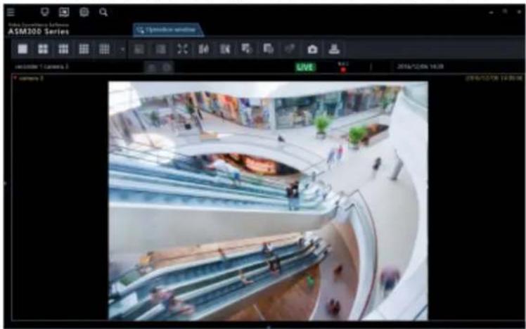
2.6.8. Alarm/event notification message
A pop-up window (notification window) will be displayed when an alarm or an error occurred. Refer to "Alarm/event notification message" for further information.
■ Alarm notification message
Notifies of an alarm occurrence.
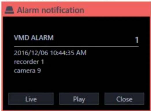
■ Event notification message
Notifies of a device error occurrence or a network error occurrence.

2.6.9. License registration message
■ License registration message
Notifies that the license for this software has not been registered.

Failover notification message 2.6.10.
Refer to the operating instructions of the failover function for further information.
■ Failover execution notification message
Sends a notification that the failover function of the recorder is executed.
The slave recorder will be switched over the stopped master recorder and work as the master recorder.

■ Alternate recorder switching notification message
Notifies that the master recorder started recording. Operation will become available by acquiring the device information of the master recorder again.

Setup Instructions 3. Setup window description 3.1.
The setup window will be launched when the [Setup] icon on the title bar of the ASM300 main page is clicked or when [Setup] is selected from the menu.
Refer to "Title bar" and "Menu" for further information about the title bar and the menu of the ASM300 main page.
Important:
- The setting window can be launched only by an administrator or a registered user who has authority. When logged in as a user other than these, the [Setting] icon on the title bar and [Setting] of the menu will not be displayed.
- Only administrators and LV0 users can configure the settings. However, LV0 users are not allowed to configure "Basic setup" on the "User mng." screen and the settings on the "Administrator setup" and "License regist." screens.
The following are descriptions about the setup window.

■ Menu buttons
When a menu button is clicked, each of the setup windows will be displayed.
■ Each setup window
A setup window of the setup menu corresponding to the clicked menu button will be displayed. When a page consists of multiple tabs, click each tab.
Important:
- To save the contents set on each setup window, it is necessary to click the [Set] button. When the [Set] button is not clicked, the edited settings will not be saved and applied.
- When the edited setting is invalid, the setup item for which the invalid setting is entered/selected will be displayed in red. When there is any setup item displayed in red, correct the invalid setting.
- Some setup items will be displayed after purchasing the Extension Software WV-ASE202, WV-ASE205, WV-ASE231 and adding the license.
- For the following setup window, restart this software after clicking the [Set] button. After restarting the software, the setting contents are reflected on the window.
- [System] - [Basic setup]
- [Device setup] ● [Face Search] - [Server registration] (It is displayed after license addition of WV-ASE231.) ● [Face Search] - [Behavior setting] (It is displayed after license addition of WV-ASE231.) ● [Face Search] - [Category setting] (It is displayed after license addition of WV-ASE231.)
- [Event] - [Alarm] • [Event] - [Alarm action]
- [Event] - [Error] ● [Communication] - [Basic setup]
- [Controller] ● [Maintenance] - [Auto delete]
The following are descriptions about each setup window.
■ System
Contains settings required for basic operation of this software.
Refer to "Settings relating to the system" for further information.
■ Device setting
Contains settings required to display live images or play recorded images, such as information of the recorders, the encoders, the cameras and the microphones.
Refer to "Settings relating to the device management" for further information.
■ User management
Contains settings relating to the user management.
Refer to "Settings relating to the user management" for further information.
■ Folder
Contains settings relating to the camera folder.
Refer to "Settings relating to folder" for further information.
■ Group
Contains settings relating to the camera group.
Refer to "Settings relating to group" for further information.
■ Sequence
Contains settings relating to the camera sequence can be configured.
Refer to "Settings relating to sequence" for further information.
■ Default screen
Contains settings relating to status of the operation window and the live window at the time of launching this software.
Refer to "Settings relating to the default screen" for further information.
■ Map
Contains settings relating to the map window.
Refer to "Settings relating to map" for further information.
■ Face Search
Contains settings relating to the face search monitor. (It is displayed after license addition of WV-ASE231.)
Refer to "Settings relating to the face search" for further information.
■ Event
Contains settings relating to the event action such as displaying of the alarm notification window, sounding the buzzer, the alarm camera direct window function, displaying of the error notification window together with sounding the buzzer, etc.
Refer to "Settings relating to the event action" for further information.
■ Communication
Contains the settings relating to the communication and the alarm notification using the Panasonic alarm protocol.
Refer to "Settings relating to the communication" for further information.
■ Controller
Configures the camera number, group number, sequence number, all of which are used when controlling through the system controller.
Refer to "Settings relating to the controller" for further information.
■ Maintenance
Displaying of the version of this software and management of the logs/the setup data are available. Refer to "Settings relating to maintenance" for further information.
■ Registration of license
Registers the license to use this software and to add extension options.
Refer to "Settings relating to the license registration" for further information.
3.2. Settings relating to the system
Configure the settings of language to use, display format of time & date, maximum number of areas, audio and image display method.
Basic setup 3.2.1.
Click the [System] button, and then click the [Basic setup] tab to display the "Basic setup" page.
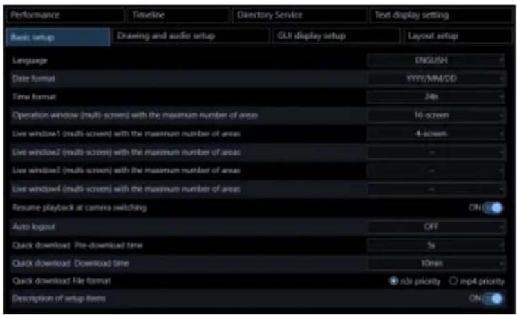
■ Language
Select the operating language.
JAPANESE
ENGLISH
FRANÇAIS
ESPAÑOL
DEUTSCH
ITALIANO
RUSSIAN
CHINESE
THAI
Default: JAPANESE
■ Date format
Select a date format from the following.
Example: In case of April 1, 2011
YYYY/MM/DD: 2011/04/01
MM/DD/YYYY: 04/01/2011
Mmm/DD/YYYY: Apr/01/2011
DD/MM/YYYY: 01/04/2011
DD/Mmm/YYYY: 01/Apr/2011
Default: YYYY/MM/DD
■ Time format
Select a time format from the following.
Example: 3 o'clock in the afternoon
12 h: 3:00:00 PM
24 h: 15:00:00
Default: 12 h
Note:
- The date format and time format will be applied in the following cases. Refer to "Operating Instructions" for each part. Status bar, information display area, alarm notification message screen, event notification message screen, each log list. • "Mmm" in "Date display format" may be replaced with "MM" for some functions such as calendar.
■ Operation window (multi-screen) with the maximum number of areas
Select a multi-screen pattern of the operation window from the following.
1-screen/ 2-screen/ 3-screen/ 4-screen/ 5-screen/ 6-screen/ 7-screen/ 9-screen/ 10-screen/ 13-screen/ 16-screen
Default: 16-screen
After the license for the Extension Software WV-ASE202 is added, select a setting value from the following.
1-screen/ 2-screen/ 3-screen/ 4-screen/ 5-screen/ 6-screen/ 7-screen/ 9-screen/ 10-screen/ 13-screen/ 16-screen/ 25-screen/ 36-screen/ 49-screen/ 64-screen
■ Maximum number of areas of live window (Available when the license for the WV-ASE202 is not added)
Select a multi-screen pattern of the live window from the following.
--/ 1-screen/ 2-screen/ 3-screen/ 4-screen/ 5-screen/ 6-screen/ 7-screen/ 9-screen/ 10-screen/ 13-screen/ 16-screen
Default: 4-screen
Note:
- When not using the live window, select "--".
- When the license of WV-ASE202 is not added, up to 20 areas as a total number of areas of the operation window and live window can be set.
- When the license of WV-ASE202 is added, up to 68 areas as a total number of areas of the operation window and live window can be set.
■ Live window1 (Available after the licenses for the WV-ASE202 are added)
Select a maximum number of areas (multi-screen pattern) of Live window 1 from the following.
--/ 1-screen/ 2-screen/ 3-screen/ 4-screen/ 5-screen/ 6-screen/ 7-screen/ 9-screen/ 10-screen/ 13-screen/ 16-screen/ 25-screen/ 36-screen/ 49-screen/ 64-screen
Default: 4-screen
■ Live window2 (Available after the licenses for the WV-ASE202 are added)
Select a maximum number of areas (multi-screen pattern) of Live window 2 from the following.
--/ 1-screen/ 2-screen/ 3-screen/ 4-screen/ 5-screen/ 6-screen/ 7-screen/ 9-screen/ 10-screen/ 13-screen/ 16-screen/ 25-screen/ 36-screen/ 49-screen/ 64-screen
Default: --
■ Live window3 (Available after the licenses for the WV-ASE202 are added)
Select a maximum number of areas (multi-screen pattern) of Live window 3 from the following.
--/ 1-screen/ 2-screen/ 3-screen/ 4-screen/ 5-screen/ 6-screen/ 7-screen/ 9-screen/ 10-screen/ 13-screen/ 16-screen/ 25-screen/ 36-screen/ 49-screen/ 64-screen
Default: --
■ Live window4 (Available after the licenses for the WV-ASE202 are added)
Select a maximum number of areas (multi-screen pattern) of Live window 4 from the following.
--/ 1-screen/ 2-screen/ 3-screen/ 4-screen/ 5-screen/ 6-screen/ 7-screen/ 9-screen/ 10-screen/ 13-screen/ 16-screen/ 25-screen/ 36-screen/ 49-screen/ 64-screen
Default: --
■ Resume playback at camera switching
Determine whether to continue playback or not when the camera is switched to the other camera during displaying playback images recorded on the recorder on the operation window.
For restrictions on "Resume playback at camera switching", refer to "Restrictions during playback continuation".
ON: Display playback images from a newly selected camera.
OFF: Display live images from a newly selected camera.
Default: ON
■ Auto logout
When a login user is inactive for a certain period of time, this software automatically terminates this session. This is called as the auto log out.
Select a time period until the auto log out is triggered from the following. When "OFF" is selected, the auto log out function will be deactivated.
■ n3r file download method (NX series)
Select a method to download the n3r-format images recorded in the NX series recorder to the PC.
Refer to "Download recorded images" about n3r file download.
Standard: Standard download method common in all recorders. Up to 1.9 GB file size is supported.
Extension: Dedicated download method for NX series. A file size exceeding 1.9 GB is supported.
Default: Standard
Note:
- The standard method uses FTP. If the file size exceeds 1.9 GB during download, the download will stop at that point.
- The extension method uses HTTP. The file will be automatically divided if the file size exceeds 1.9 GB. The available download method may differ depending on the recorder model or version.
| recorder | version | n3r file download method |
| NX200, NX300, NX400 | 2.50 or later | Extension |
| Standard | ||
| Below 2.50 | Standard | |
| NX100 | 1.10 or later | Extension |
| Below 1.10 | Standard | |
| ND200, ND300, ND400, HD300, HD600, NV200, NV250, NV300 | - Standard |
- If the recorder does not support the extension method, the standard download will be executed even if “Extension” is selected.
- In the case of the extension method, the user connection is maintained until the download is completed. When the number of users exceeds the limit, the connection with the recorder drops and the download will be cancelled at that point.
■ Quick download Pre-download time
Select a pre-download time from the following to determine how many seconds before the pre-download starts before starting a quick download.
Refer to "→ Use the quick download" for the quick download.
0s/ 5s/ 10s/ 15s
Default: 5s
■ Quick download Download time
Select a download time from the following to determine the download time of the quick download.
Refer to "Use the quick download" for the quick download.
Select the file format of the image to be downloaded by the quick download from the following.
Refer to "Use the quick download" for the quick download.
n3r priority: Downloads an image file in n3r format.
mp4 priority: Downloads an image file in mp4 format. If download of an image file in mp4 format is unavailable, an image in n3r format will be downloaded.
Default: n3r priority
Important:
- Download of image files in mp4 format is available if using NX400 (version 2.0 or later), NX300 and NX200 (version 1.1 or later). If using another model or a firmware version that is not supported to use this function, image files in n3r format will be downloaded even if "mp4 priority" is selected. The available functions vary depending on the firmware version of the recorder. Refer to the operating
instructions of the recorder for further information.
- In the same manner, if download of an image in the specified format is unavailable, the image will be downloaded in a format supported by the recorder in use.
■ Description of setup items
Determine whether to display the description of the item using the tool tip when the cursor is moved over the buttons on "Basic setup", "Drawing and audio setup", or "GUI display setup".
ON: Displays the description using the tool tip.
OFF: Does not display the description using the tool tip.
Default: ON
- Separate a tab
Determine the tab separation availability for the live monitor, map monitor, and search screen.
Enable: The tab can be separated into a different window.
Disable: The tab cannot be separated into a different window.
Default: Enable
Note:
- When this software is restarted while the tab is separated and "Disable" is selected, the tab will be combined with the window. At that time, the order of the tabs is "Operation", "Setup" (displayed before exiting the software), "Live window", "Map window", and "Search window" from the left.
■ [Set] button
The configured settings will be saved.
Important:
• After clicking the [Set] button, restart this software to apply the settings.
3.2.2. Drawing and audio setup
Click the [System] button, and then click the [Drawing and audio setup] tab to display the "Drawing and audio setup" page.

■ Image display method
Select how to display the image area.
- Aspect ratio: The aspect ratio of images will be maintained. • Scaling: The displayed images will be enlarged/reduced to fit in the whole of the image area.
- Pixel by Pixel: The images will be displayed in the original size without enlargement/reduction.
- Aspect ratio (type 2): The aspect ratio of images will be maintained. This is the function improved version that improved the image display area assignment method. Display of images with a larger size is available, although the CPU load will increase.
Default: Aspect ratio (type 2)
Note:
- When receiving images from Video Insight Server, "Aspect ratio" will automatically be applied to display images in the image display area even if selecting "Scaling" or "Pixel by Pixel".
■ Fisheye display mode (Fisheye camera)
Select a display mode to determine how to display images captured by a fisheye camera whose image capture mode is "Fisheye" when receiving them.
Fisheye: Display images without any change.
Single PTZ: Fisheye images will be displayed in the Single PTZ format.
Quad PTZ: Fisheye images will be displayed in the Quad PTZ format.
Panorama: Fisheye images will be displayed in the Panorama format.
Double Panorama: Fisheye images will be displayed in the Double Panorama format.
Default: Fisheye
Note:
- It may be possible that "Fisheye" is applied even though another parameter is selected for [Fisheye display mode (Fisheye camera)] depending on the live window in use. The selected parameter will be correctly applied only when displaying on the following monitor.
- When an option of WV-ASE202 is not added: Operation window/Live window
- When an option of WV-ASE202 is added: Operation window/Live window 1
- It may be possible that “Fisheye” is applied even though another parameter is selected for [Fisheye display mode (Fisheye camera)] depending on the number of areas on a multi-screen in use. The selected parameter will be correctly applied only when displaying on 1-screen, 2A-screen, 2B-screen, 4-screen, on left area of 3A-screen, on right area of 3B-screen, and on large area of 7-/10-/13-screen.
- [Fisheye image format (Fisheye)] is available only for live images or playback of recorded images. SD playback images are not supported.
- When the display format is changed on [Fisheye display menu] of the operation window, the changed display format will be applied to images after the change.
- Even when [Single PTZ], [Quad PTZ], [Panorama] or [Double Panorama] is selected, depending on the network device environment or the PC in use, fisheye images may be displayed for a moment when displaying images from the camera.
- When [Single PTZ] or [Quad PTZ] is selected, the display position of images from the camera may be momentarily different from the previous display position at the time of displaying images from the camera.
■ Single PTZ/Quad PTZ display format for fisheye image (3M fisheye camera)
Select a correction method for when displaying fisheye images received from 3M fisheye camera in the single PTZ display or in the quad PTZ display.
Entire image correction: Method that averagely corrects distortion of an entire image.
Center part correction: Method that mitigates distortion especially around the center of an image.
Peripheral edges of image will be displayed distorted when compared with the entire image correction.
Default: Entire image correction
■ High-speed playback smooth mode
Select whether or not to use the high-speed playback smooth mode.
ON: Use
OFF: Not use
Default: OFF
■ Smooth display (Buffering)
Select whether or not to use the buffer for images.
ON: Images will temporarily be stored in the PC for smooth display.
OFF: Images will not be stored in the PC and be displayed in real time.
Default: OFF
Note:
• The setting will be validated only when using the operation window in 1-/4-/9-/16-screen. - When "ON" is selected, image display delay may occur. - When "ON" is selected, a large amount of memory will be required. When using on a 32-bit OS, it is recommended to set this setting to off.
■ Halftone (Anti-aliasing)
Determine whether to display images while reducing jaggies (stair-like lines that often appear on a diagonal or a curved line) or not when displaying images.
ON: Display images while reducing jaggies.
OFF: Display images without any processing.
Default: OFF
Note:
• The setting will be validated only when using the operation window in 1-/4-/9-/16-screen. - When "ON" is selected, CPU load may become high. Images may be displayed with delay or not be displayed depending on the operating environment. - When "ON" is selected, contour of images may sometimes be blurred.
■ Contrast enhanced display (RGB:0-255)
Determine whether or not to enhance the contrast of images to display.
ON: Displays images by expanding RGB signal range from "16-235" to "0-255".
OFF: Displays images with RGB signal range of "16-235".
Default: OFF
Note:
• The setting will be validated only when "H.264" or "H.265" is set for the image format. • Depending on a subject to display, blown-out highlights may appear in high bright areas.
■ Audio
Determine whether to use or not use the audio function.
ON: Use the audio transmission/reception function.
OFF: Not use the audio transmission/reception function.
Default: OFF
Note:
- When displaying images on a multi-screen, audio will be output from the camera displayed in the upper-left area of the multi-screen.
■ Volume level boost during sound collection (Network microphone)
Select the volume compensation level for the network microphone when the sound collection position is enabled.
OFF: Disables compensation.
Low: Slightly boosts the volume.
High: Greatly boosts the volume.
Default: OFF
■ Drawing method
Select the image drawing method.
GDI: A common method for Windows OS.
Direct2D: Reduces non-smooth movement and provides fast drawing.
Default: GDI
Important:
- Use "Direct2D" on a PC with the latest graphic driver.
- Use "Direct2D" after setting "ON" to "Smooth display (Buffering)".
- "Direct2D" is available for up to 16-screen of the operation window. For 25-screen and more or for the live window, use "GDI".
Note:
• This setting cannot be configured on Windows Vista or Windows 7. GDI is the only option.
■ PC diagnosis (4K camera)
Diagnose whether the PC in use is suitable to display H.264 images in 4K resolution transmitted from the camera and set according to the result. When the [Diag.] button is clicked and the diagnosis ends, a pop-up window will appear and display the diagnosis result.
The setting can be changed only when the following conditions are met:
The OS of the PC in use is Microsoft® Windows® 8.1 or later. The OS of the PC in use is 64-bit. The memory of the PC in use is more than 8 GB. The PC in use supports Hardware decoder (QSV).
• Normal: Supports display of images with up to 9M (2992×2992).
• 4K: Supports display of images with up to 12M (4000×3000).
Default: Normal
Note:
• This diagnosis function checks only the availability of the above functions on the PC in use. Even when
the diagnosis conditions are fulfilled, it does not mean that display ability of 4K images is guaranteed.
- When displaying images whose image capture size is larger than 9M (2992x2992) in the "Normal" mode, image quality may become lower than the actual image quality since the image capture size is reduced.
- If a pop-up screen saying "Hardware decoder (QSV) is not available." is displayed, check the following items.
The CPU is Core i7 7700 or faster. The version of Intel HD Graphics is 15.36.21.64.4222 or later. The latest version of the driver can be downloaded from the following: URL: https://downloadcenter.intel.com/ Download a driver corresponding to the CPU in use and install it on the PC.
- "Graphic function built-in the PC (built-in video)" is enabled on the BIOS setting.
The name of the BIOS setting differs depending on the PC in use.
• Even if "4K" is selected, H.264 images will be decoded by software.
Set "Decoding method (H.265)" for the H.264 image decoding method.
- This setting will not be included when performing "Save as a backup" and "Load the setup file" on the "Maintenance" screen. Refer to "Settings relating to maintenance" for the maintenance.
■ Decoding method (H.265)
Diagnose whether the PC in use supports the hardware decoding of H.265 images transmitted from the camera and set according to the result.
Turn off all images on the live window and the operation window and then click the [Diag] button. A pop-up window will appear and display diagnosis result.
The OS of the PC in use is Microsoft® Windows® 10 or later. The PC in use shall support the hardware decoder (for H.265).
- Software: Decodes H.265 images using software. Supports display of images with up to 9M (2992×2992).
- Hardware: Decodes H.265 images using hardware. Supports display of images with up to 12M (4000×3000).
Default: Device tree
Important:
- In order to use this function, you need to connect at least one of the internal display output of the PC to the display. This function can not be used when the display is output only from the video card.
- In this case, connect the display to the built-in video output of the PC and restart this software and then click the [Diag] button again.
Note:
- This diagnosis function checks only availability of the above functions on the PC in use. Even when the diagnosis conditions are fulfilled, it does not mean that display ability of H.265 images is guaranteed.
- If a pop-up screen saying "The CPU may be a model that does not support the hardware decoder (for H.265)." is displayed, check the following items.
The CPU shall be the 7th generation Intel® Core processor or later. The version of Intel HD Graphics is 22.20.16.4574 or later. The latest version of the driver can be downloaded from the following: URL: https://downloadcenter.intel.com/ ➢ Download a driver corresponding to the CPU in use and install it on the PC.
• If a pop-up screen saying "The built-in display output of the PC may not be connected with the display." is displayed, check the following items.
display." is displayed, check the following items.
To use this function, it is necessary to connect at least one of the built-in display outputs of the PC to a display. If outputting to the display only from the video card, this function is unavailable.
- "Graphic function built-in the PC (built-in video)" is enabled on the BIOS setting.
The name of the BIOS setting differs depending on the PC in use.
- This setting will not be included when performing "Save as a backup" and "Load the setup file" on the "Maintenance" screen. Refer to "Settings relating to maintenance" for the maintenance.
The following two tree display formats are available.
The following two tree display formats are available.
Folder tree: Display cameras in folder tree format.
Folder tree: Display cameras in folder tree format.
Refer to "Settings relating to folder" for editing of folders and cameras displayed in folder tree form.
Refer to “Settings relating to folder” for editing of folders and cameras displayed in folder tree form.
■ Display format when selecting camera
Select a live image display method in case that a camera icon in the device tree or the map is clicked.
1-screen display: Display live images on 1-screen.
Display images on the selected area: Display live images on the area with the selection frame.
Default: Display on the selected area
■ Save a still picture
Select a resolution of still image to be saved.
Display resolution: Save with the resolution at the time when the image was being displayed on the live window or the operation window.
Original resolution: Save with the resolution at the time when the image was transferred from the camera.
Default: Display resolution
Note:
- When the license of WV-ASE231 is being added, it will automatically be changed to "Original resolution".
- When [Display resolution] is selected, a still image will be saved as a JPEG image.
- When [Original resolution] is selected, a still image will be saved as a BMP image.
- Even if "Original resolution" is selected, a still image with resolution larger than 9M (2992 x 2992) will be saved with reduced resolution when "Standard" is selected for "PC compatibility diagnosis (4K)". When "4K" is selected for "PC compatibility diagnosis (4K)", a still image with resolution larger than 9M (2992 x 2992) will be saved without reducing the resolution.
■ Stream (NX series) in multi-display
Selects the recording stream for displaying images recorded with NX-series in multiple display.
Stream 1: Plays with "Stream 1".
Stream 2: Plays with "Stream 2".
Default: Stream 1
Note:
- When displaying on 1-screen, "Stream 1" will be selected.
■ Display video information
Select whether to display the information of the image displayed on the live window or operation window.
When "ON" is selected, the image information from the top will be displayed.
Received bit rate: Indicates the bit rate when the image distributed from the device is received by this software.
Received frame rate: Indicates the frame rate when the image distributed from the device is received by this software.
Displayed frame rate: Indicates the frame rate of the image displayed with this software.
Note:
- The image information to be displayed is for reference. The actual value may be different depending on the network status.
■ Text color of video information
Select the text color to display the information of the image displayed on the live window or operation window.
■ [Set] button
The configured settings will be saved.
GUI display setup 3.2.3.
Click the [System] button, and then click the [GUI display setup] tab to display the "GUI display setup" page.

■ Full screen display when opening the operation window
Select whether or not to automatically provide full screen display of the operation window immediately after logging in. This item is enabled when a group is set as a default screen.
ON: Full screen display enabled
OFF: Full screen display disabled
Default: OFF
■ Panasonic logo
Determine whether to display the Panasonic logo on the application title or not.
ON: Display the logo
OFF: Not display the logo
Default: ON
■ Display the panel open/close button
Determine whether to display or hide the panel open/close button on each of the operation window and live window.
ON: The open/close button will be displayed. Displaying/hiding of the menu panel and the operation panel of the operation window and the live window can be operated by this open/close button.
OFF: The open/close button will be hidden.
Default: ON
■ Alarm log display
Determine whether to display or hide the alarm log panel of the operation window.
ON: Display the alarm log panel.
OFF: Hide the alarm log panel.
Default: ON
Note:
- When "OFF" is selected for "Alarm log display", the panel name will be changed from [Alarm log] to [Buzzer] and only the [Buzzer stop] button will be displayed.
■ Device error log display
Determine whether to display or hide the device error log panel of the operation window.
ON: Display the device error log panel.
OFF: Hide the device error log panel.
Default: ON
■ Network error log display
Determine whether to display or hide the network error log panel of the operation window.
ON: Display the network error log panel.
OFF: Hide the network error log panel.
Default: ON
■ Display of icon name on map
Determine whether to display a name of an icon placed on a map of the map window and map setup window under the icon or not.
ON: Display an icon name.
OFF: Not display an icon name.
Default: ON
■ Map window preview image display
Determine whether to display preview images of a camera or not when the mouse cursor is moved onto the camera icon arranged on the map of the map monitor window.
ON: Display a preview image
OFF: Not display a preview image
Default: ON
■ Icon frame display on the map setting window
Determine whether to display a frame border around the camera icon arranged on the map of the map monitor window or not.
ON: Displays a frame border around the camera icon.
OFF: Does not display a frame border around the camera icon.
Default: OFF
■ [Set] button
The configured settings will be saved.
Layout setup 3.2.4.
Click the [System] button, and then click the [Layout setup] tab to display the "Layout setup" page.

■ Page layout icon
Select 5 or less icons on the top line of the pull-down menu of the page layout icon to display them on the tool bar of the operation window.
| Icon | Description | Icon | Description |
 | Display images on 1-screen. |  | Display images on 2A-screen. |
 | Display images on 2B-screen. |  | Display images on 3A-screen. |
 | Display images on 3B-screen. |  | Display images on 3C-screen. |
 | Display images on 4-screen. |  | Display images on 4E-screen. |
 | Display images on 5-screen. |  | Display images on 6-screen. |
 | Display images on 6A-screen. |  | Display images on 7-screen. |
 | Display images on 7A-screen. |  | Display images on 9-screen. |
 | Display images on 10-screen. |  | Display images on 13-screen. |
| Display images on 16-screen. | |||
The following are available after the license for the WV-ASE202 is added.
| Icon | Description | Icon | Description | |
 | Display images on 25-screen. |  | Display images on 36-screen. | |
 | Display images on 49-screen. |  | Display images on 64-screen. | |
Selectable layout varies depending on the setting for [Operation window (multi-screen) with the maximum number of areas] of [Basic setup] under [System setup].
- In case that the maximum number of areas of the operation window is 1-screen 1-screen
Default: 1
- In case that the maximum number of areas of the operation window is 2-screen 1-screen/ 2A-screen/ 2B-screen
Default: 1-screen/ 2A-screen/ 2B-screen
- In case that the maximum number of areas of the operation window is 3-screen 1-screen/ 2A-screen/ 2B-screen/ 3A-screen/ 3B-screen/ 3C-screen
Default: 1-screen/ 2A-screen/ 3A-screen/ 3B-screen/ 3C-screen
• In case that the maximum number of areas of the operation window is 4-screen 1-screen/2A-screen/2B-screen/3A-screen/3B-screen/3C-screen/4-screen/4E-screen
Default: 1-screen/ 2A-screen/ 2B-screen/ 4-screen/ 4E-screen
• In case that the maximum number of areas of the operation window is 5-screen 1-screen/ 2A-screen/ 2B-screen/ 3A-screen/ 3B-screen/ 3C-screen/ 4-screen/ 4E-screen/ 5-screen
Default: 1-screen/ 2A-screen/ 2B-screen/ 4-screen/ 5-screen
- In case that the maximum number of areas of the operation window is 6-screen 1-screen/ 2A-screen/ 2B-screen/ 3A-screen/ 3B-screen/ 3C-screen/ 4-screen/ 4E-screen/ 5-screen/ 6-screen/ 6A-screen
Default: 1-screen/ 2A-screen/ 4-screen/ 6-screen/ 6A-screen
- In case that the maximum number of areas of the operation window is 7-screen 1-screen/ 2A-screen/ 2B-screen/ 3A-screen/ 3B-screen/ 3C-screen/ 4-screen/ 4E-screen/ 5-screen/ 6-screen/ 6A-screen/ 7-screen/ 7A-screen
Default: 1-screen/ 4-screen/ 6-screen/ 7-screen/ 7A-screen
- In case that the maximum number of areas of the operation window is 9-screen 1-screen/ 2A-screen/ 2B-screen/ 3A-screen/ 3B-screen/ 3C-screen/ 4-screen/ 4E-screen/ 5-screen/ 6-screen/ 6A-screen/ 7-screen/ 7A-screen/ 9-screen
Default: 1-screen/ 2A-screen/ 4-screen/ 6-screen/ 9-screen
- In case that the maximum number of areas of the operation window is 10-screen 1-screen/ 2A-screen/ 2B-screen/ 3A-screen/ 3B-screen/ 3C-screen/ 4-screen/ 4E-screen/ 5-screen/ 6-screen/ 6A-screen/ 7-screen/ 7A-screen/ 9-screen/ 10-screen
Default: 1-screen/ 4-screen/ 6-screen/ 9-screen/ 10-screen
- In case that the maximum number of areas of the operation window is 13-screen 1-screen/ 2A-screen/ 2B-screen/ 3A-screen/ 3B-screen/ 3C-screen/ 4-screen/ 4E-screen/ 5-screen/ 6-screen/ 6A-screen/ 7-screen/ 7A-screen/ 9-screen/ 10-screen/ 13-screen Default: 1-screen/ 4-screen/ 6-screen/ 9-screen/ 13-screen
- In case that the maximum number of areas of the operation window is 16-screen
1-screen/ 2A-screen/ 2B-screen/ 3A-screen/ 3B-screen/ 3C-screen/ 4-screen/ 4A-screen/ 4B-screen/
4C-screen/ 4D-screen/ 4E-screen/ 5-screen/ 6-screen/ 6A-screen/ 7-screen/ 7A-screen/ 9-screen/
10-screen/ 13-screen/ 16-screen
Default: 1-screen/ 4-screen/ 6-screen/ 9-screen/ 16-screen
- When the maximum number of areas of the operation window is 25-screen (Available when the license for the WV-ASE202 is added)
1-screen/ 2A-screen/ 2B-screen/ 3A-screen/ 3B-screen/ 3C-screen/ 4-screen/ 4A-screen/ 4B-screen/
4C-screen/ 4D-screen/ 4E-screen/ 5-screen/ 6-screen/ 6A-screen/ 7-screen/ 7A-screen/ 9-screen/
10-screen/ 13-screen/ 16-screen/ 25-screen
Default: 1-screen/ 4-screen/ 9-screen/ 16-screen/ 25-screen
- When the maximum number of areas of the operation window is 36-screen (Available when the license for the WV-ASE202 is added)
1-screen/ 2A-screen/ 2B-screen/ 3A-screen/ 3B-screen/ 3C-screen/ 4-screen/ 4A-screen/ 4B-screen/
4C-screen/ 4D-screen/ 4E-screen/ 5-screen/ 6-screen/ 6A-screen/ 7-screen/ 7A-screen/ 9-screen/
10-screen/ 13-screen/ 16-screen/ 25-screen/ 36-screen
Default: 1-screen/ 4-screen/ 9-screen/ 16-screen/ 36-screen
- When the maximum number of areas of the operation window is 49-screen (Available when the license for the WV-ASE202 is added)
1-screen/ 2A-screen/ 2B-screen/ 3A-screen/ 3B-screen/ 3C-screen/ 4-screen/ 4A-screen/ 4B-screen/
4C-screen/ 4D-screen/ 4E-screen/ 5-screen/ 6-screen/ 6A-screen/ 7-screen/ 7A-screen/ 9-screen/
10-screen/ 13-screen/ 16-screen/ 25-screen/ 36-screen/ 49-screen
Default: 1-screen/ 4-screen/ 9-screen/ 16-screen/ 49-screen
- When the maximum number of areas of the operation window is 64-screen (Available when the license for the WV-ASE202 is added)
1-screen/ 2A-screen/ 2B-screen/ 3A-screen/ 3B-screen/ 3C-screen/ 4-screen/ 4A-screen/ 4B-screen/
4C-screen/ 4D-screen/ 4E-screen/ 5-screen/ 6-screen/ 6A-screen/ 7-screen/ 7A-screen/ 9-screen/
10-screen/ 13-screen/ 16-screen/ 25-screen/ 36-screen/ 49-screen/ 64-screen
Default: 1-screen/ 4-screen/ 9-screen/ 16-screen/ 64-screen
Note:
- When the setting for [Operation window (multi-screen) with the maximum number of areas] is changed, [Page layout icon] will automatically be changed to the default in accordance with the maximum number of areas.
- 4M-screen is not displayed on the screen layout of the toolbar of the operation monitor because it is a layout dedicated to group display where only the multi-sensor camera can be placed.
■ [Set] button
The configured settings will be saved.
Performance 3.2.5.
Click the [System] button, and then click the [Performance] tab to display the "Performance setup" page.
Enter a number of images to be refreshed per second.

Note:
- Change the setting value for the maximum refresh interval of JPEG/VGA (live/playback) according to your operation environment.
Intel ® Core TM i5: 240 ips
Intel ® Core TM i7: 300 ips
(For reference) Intel ® CoreTM 2 Duo 2.66GHz: 160 ips
- The maximum refresh interval per screen is calculated by dividing the maximum refresh interval by the number of screens of VGA conversion.
Ex. 1) When displaying VGA (640×480) image while "60 ips" is set for "Maximum refresh interval", the maximum refresh interval per area will be 60 ips when displaying in 1-screen, and 15 ips when displaying in 4-screen. Ex. 2) When displaying SXVGA (1280×960, 4VGA conversion) image while "120 ips" is set for "Maximum refresh interval", the maximum refresh interval per area will be 30 ips when displaying in 1-screen, and 7.5 ips when displaying in 4-screen.
- In a similar manner, the maximum refresh interval of "JPEG/VGA (Live/Playback)" will be x1/21, x1/19, x1/16, x1/10, x1/4, x2/3, and x4 of the set value respectively when the resolution is 9M (2992×2992), 8M (2816×2816), 5M (2560×1920), QXGA (2048×1536), SXVGA (1280×960), SVGA (800×600), QVGA (320×240).
*1 When "Partial" is selected for the scan mode of NP100x, the resolution will be 960x720.
- When displaying images directly from the cameras, the smallest value among the refresh intervals set on the "Camera setup" window will be the maximum refresh interval per area.
- The actual refresh interval may become slower than the set refresh interval depending on the network environment, the settings of the camera and the maximum refresh interval set on the "System" page.
- The maximum refresh interval of MPEG-4, H.264 or H.265 images cannot be controlled with this software. • Refer to "Recommended camera setup" for further information.
- When a program of the recorder changed the recording rate, images sometimes may not be refreshed exactly at the set refresh interval.
- Select a value that is 15 ips or less for the live rate per HD300 (Number of ASM300 x HD300 (Live)).
■ JPEG/VGA (Live/Playback)
Enter a number among the following for the maximum refresh interval of 1 second for the whole system when displaying JPEG images of VGA size (640x480).
1 ips - 500 ips
Default: 200 ips
Note:
- When receiving images from Video Insight Server, images will be displayed at the image refresh rate of the camera or the recorder.
■ HD300 (Live)
Enter a number among the following for the maximum refresh interval of 1 second for the whole system when displaying JPEG images of VGA size (640x480).
1 ips - 15 ips
Default: 5 ips
■ [Set] button
The configured settings will be saved.
Timeline 3.2.6.
Click the [System] button, and then click the [Timeline] tab to display the Timeline setup window.
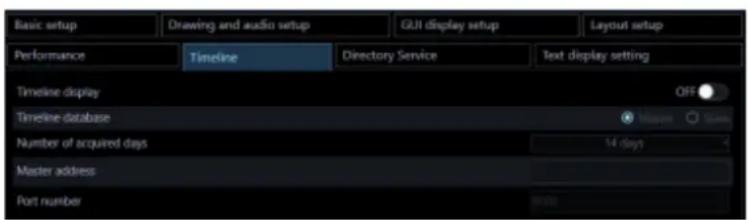
Note:
- When the timeline setting is changed, it may become inoperable for several minutes due to the pause of the service.
- When setting the timeline, first synchronize the PC clock with the recorder. When the clocks are not synchronized, or when the PC clock has been changed, the timeline will not be displayed correctly. If this happened, initialize the timeline after synchronizing the PC clock with the recorder. Refer to “Save/load/initialize the timeline data” for how to initialize the timeline.
■ Timeline display
Select to determine whether or not to display timeline on the playback operation panel of the operation window.
ON: Displays the timeline playback operation panel.
OFF: Displays the playback operation panel.
Default: OFF
■ Timeline database
Determine whether the PC in which this software is installed is to be used as the master PC that manages the timeline database or not.
Master: Use as the master PC.
Slave: Use as the slave PC.
Default: Master
Note:
- When using a plurality of this software, set only a single one as "Master".
- The maximum number of slave PCs that can be connected simultaneously to the Master is limited to 16 PCs.
■ Number of acquired days
Set number of days to acquire recording information from the recorder.
Selection of number of days to acquire recording information will become available by setting "Master" for "Timeline database".
3 days: Acquire recording information of the last 3 days. 7 days: Acquire recording information of the last 7 days. 14 days: Acquire recording information of the last 14 days. 30 days: Acquire recording information of the last 30 days. 90 days: Acquire recording information of the last 90 days.
Default: 14 days
Note:
- Depending on number of the registered recorder or number of the recording event, it may sometimes be impossible to acquire recording information due to the limitation of storage capacity.
■ Master address
Set the master destination address. Enter an address using up to 255 alphanumeric characters including "." (period) and "-" (hyphen). Setting of the master address will become available by setting "Slave" for "Timeline database".
Note:
- It is impossible to connect the master address via WAN. Make connection via LAN.
■ Port number
Enter a number among the following for the port number.
1 - 65535
Default: 8080
■ [Set] button
The configured settings will be saved.
Directory Service 3.2.7.
User management can be performed associated with Windows Server 2012 Active Directory function.
Click the [System] button, and then click the [Directory Service] tab to display the "Directory Service" page.
Important:
- Register the group to which one user belongs to the LDAP Server within 1000 or less.

■ Directory Service
Select to determine whether to use the Directory Service.
ON: Use
OFF: Not use
Default: OFF
■ LDAP Server Address
Enter the address of Windows Server on which Active Directory is running (IP address or the host name in FQDN format) using 255 characters at maximum.
■ LDAP Server Port
Enter the port number for the Active Directory Service.
Default: 389
■ LDAP Schema
Select LDAP Schema. Currently only "Active Directory" can be selected.
■ LDAP Base DN
Enter the domain name of the Active Directory Server by LDAP DN (512 characters at maximum).
Multiple LDAP relative distinguished names are listed in the comma delimited format.
Example: In the case of a fictitious domain "panasonic.com"
DC=panasonic, DC=com
■ LDAP Binding DN
Enter the user name to be connected to the Active Directory Server by LDAP DN (512 characters at maximum).
Example: In the case of "Panasonic User" that belongs to a user group registered in the fictitious domain "panasonic.com"
CN=Panasonic User, CN=Users, DC=panasonic, DC=com
■ LDAP Password
Enter the password of the user to be connected to the Active Directory Server.
The entered password will be displayed with asterisks (*). Enter 1 - 128 characters for the password.
Note:
- Regarding Active Directory and LDAP, it is necessary to understand the functions of Windows Server 2012. Set up the Directory Service properly according to your environment.
- Microsoft® Windows® Server 2012 Standard, Microsoft® Windows® Server 2012 R2 Standard are supported.
- When accessing the Active Directory, "Windows Server 2012 CAL" is required.
■ [Set] button
The configured settings will be saved.
Important:
• After clicking the [Set] button, restart this software to apply the settings.
Text display setting 3.2.8.
This setting will be displayed when the license for the extension software (WV-ASE205) is added. Click the [System] button, and then click the [Text display setting] tab to display the "Text display setting" page.

■ Visibility Enhancement Text Display
Select ON or OFF to determine whether to display the text indicating that the visibility enhancement is on.
ON: Display
OFF: Not display
Default: ON
Note:
- This "text" indicates "This image is enhanced." displayed in image.
■ Display position
Select a position of the text indicating that the visibility enhancement is on.
Upper left: The text will be displayed at the upper left of the image.
Upper middle: The text will be displayed at the upper middle of the image.
Upper right: The text will be displayed at the upper right of the image.
Lower left: The text will be displayed at the lower left of the image.
Lower middle: The text will be displayed at the lower middle of the image.
Lower right: The text will be displayed at the lower right of the image.
Default: Upper left
■ [Set] button
The configured settings will be saved.
Important:
• After clicking the [Set] button, restart this software to apply the settings.
3.3. Settings relating to the device management
Adds/ corrects/ deletes devices. Automatically detect devices connected to the same network as this software and set the device from this software.
There are the following types of device setup.
| Setting window | Description |
| Initial setup | Use when setting devices that are in the initial state. Sets an IP address and administrator information of a camera or recorder that is in the initial state. Also automatically associates a camera with a recorder and registers in this software. |
| Advanced setup | Use when setting devices in more detail. Associates a camera with a recorder, changes settings of a device and registers a microphone or a stand-alone camera in this software. |
| Device registration | Use when registering devices already set up in advance to this software. |
| External device connection | Register an external device that can be registered by an optional license to this software. |
The items that can be set on each screen are as follows.
○: Settable, ×: Unsettable
| Setting function | Initial setup | Advanced setup | Device registration |
| Auto device detection | ○ ○ ○ | ||
| Registration of recorders and devices that are registered in the recorder to this software | ○ ○ ○ | ||
| Registration/deletion of cameras and encoders to/from a recorder | ○ ○ × | ||
| Batch setup of administrator information of cameras or recorders that are in the initial state | ○ ○ × | ||
| Batch setup of IP addresses of cameras or recorders that are in the initial state | ○ × × | ||
| Registration of a camera alone to this software | × ○ ○ | ||
| Registration of an encoder alone to this software | × ○ ○ | ||
| Deletion of device information from this software | × ○ ○ | ||
| Interlocking registration of a camera and a network microphone | × ○ ○ | ||
| Setup of a device that is not detected by the auto detection | × ○ ○ | ||
| Individual setup of IP address of device | × ○ × | ||
| Recording setup of recorder | × ○ × | ||
| Change of setting information of devices | × ○ × |
Restriction when setting device 3.3.1.
There are following restrictions for each function when configuring device with this software.
Read the following before operating this software.
(1) Corresponding function of recorder
The supported recorders for the automatic detection function (automatically detect the device connected to the same network as this software) and the setting transmission function (the function to set the device from this software) are as follows.
○ : Supported, × : Not supported
| Automatic detection | Setting transmission | Recorder model |
| ○ ○ | NV300, NX200, NX300, NX400 | |
| ○ × | NV200 | |
| × ○ | ND400 | |
| × × | ND200, ND300, HD600, HD300, Video Insight Server |
When using NV200, NV300, NX200, NX300 or NX400, connect to the "Camera/PC port". If connected to the "PC port", detection will not be performed. Refer to the operating instructions of each recorder for further information about the network port.
(2) Supported functions of devices other than recorder
The following are devices (other than recorder) that support the auto detection function and the setting transmission function.
| Device type Model | |
| Encoder | GXE100 |
| GXE500 | |
| Camera | i-Pro camera (*Excluding some models.) |
| Microphone SMR10 |
*Multi-sensor camera cannot change setting from this software.
(3) Other notes
- To add a device not compatible with the automatic detection function, use Off-line addition (Refer to "Manually add a device")
- Cannot detect devices connected wirelessly.
- When using other tools (Panasonic Security System Configuration Tool, Easy IP Setup Tool etc.) with automatic detection function at the same time, the detection function of this software can not be used. Do not start other tools when detecting devices.
- In the setting window, input items not supported by each device may be displayed. For the corresponding function of each device, please refer to the owner's manual of your device.
- Depending on the communication environment and the state of the target device, device connection may fail.
- If the setting made by this software is inconsistent on the device side, that setting will not be reflected on the device.
- When using a V-series camera, changing the settings is unavailable except for some items. To change the camera settings, use the camera's browser or the recorder in use.
- When using a V-series camera, it may take several minutes for the change to be reflected on the camera after changing "Compression". During that time, even if the setting is correct, "Image reception error" etc. may occur.
- If user authentication with a V-series camera fails four times, login to the camera will become unavailable temporarily. In this case, retry to log in after waiting for a while or log in after rebooting the camera. Refer to the operating instructions of the camera for further information.
- The authentication method for devices registered in this software will not be updated by re-acquiring the device information. Therefore, when changing the authentication method, be sure to change it manually.
- To enhance network security, it is recommended to set the authentication method with the device to "Digest" authentication and the communication method to "SSL/HTTPS".
Initial setup 3.3.2.
Set the device in the initial state. Sets an IP address and administrator information of a camera or recorder that is in the initial state. Also automatically associates a camera with a recorder and registers it in this software.
Important:
- To register independent cameras or network microphones in this software, do so from "Advanced setup" or "Device setup".
- When SSL communication is used between the recorder and the PC, configuration of the device setting using the "Initial setup" is unavailable. In this case, configure the setting from "Advanced setup" or "Device setup" in the same way.
- When changing a device, re-acquire device information from the "Device registration" window. Refer to "Replace a device" for further information.
Click the [Device setup] button and then click the [Initial setup] button.

Since the start confirmation message of "Initial setup" is displayed, click the [OK] button.
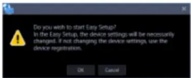
The detection progress window will be displayed and detection of devices connected to the network will start.

When the device detection is completed, the detection progress window will close.
→ “Step1 Device detection” will be displayed.
Important:
- When using NV200, NV300 or NX-series, connect to the "Camera/PC port". If connected to the "PC port", detection will not be performed. • Refer to the operating instructions of each recorder for further information about the network port.
3.3.2.1. Step1 Device detection
When the "Step1 Device detection" window is displayed, information of devices connected to the network will automatically be acquired and be displayed in list form.
Enter the user name and password for device to be registered to "User name" and "Password" of "Device list" respectively and then click the [Next] button.
→ Shifts to "Step2 Camera registration".

The details of the window are as follows.
■ Device list
Information of devices connected to the network will be displayed in list form.
| Item | Description |
| Icon | Registration status of administrators will be displayed with icons.+: Administrator information is already set in device+: Administrator information is not yet set in device (Device requires initial registration of administrator): Device that is in condition of being uniquely unable to identify the administrator status (Device outside the network segment) |
| Device type | Device type will be displayed.One of camera/ recorder/ microphone/ encoder will be displayed. |
| Address | Address of a device will be displayed. |
| Port number | A Port number of a device will be displayed. |
| (Recorder icon) | When the failover function of the recorder registered in this software is enabled, the following icons are displayed. It indicates that a recorder having the failover function is monitoring an error. It indicates that a recorder having the failover function is monitoring an error. It indicates that a recorder having the failover function is executing a failover. It indicates that a recorder having the failover function is executing a failover. |
| Model no. | A model number of a device will be displayed. |
| Result | (A blank for “Step1 Device detection”) |
| Device title | A title of a device will be displayed. |
| MAC address | A MAC address of a device will be displayed. |
| User name | Enter the administrator name registered in the device.When nothing is entered (blank), the cell will be displayed in red.Default: (When it is unregistered, nothing (blank) is displayed. When it is registered, a user name will be displayed.) |
| Password | Enter the password for the administrator registered in the device.When nothing is entered (blank), the cell will be displayed in red.Default: (When it is unregistered, nothing (blank) is displayed. When it is registered, the password will be displayed in “●.”) |
| Authentication | Select the user authentication method. It is not available if the device is not compatible with the recorder or the Digest authentication. Also, the selected authentication method is to be used for software connection, and it does not affect the device settings. When the recorder authentication method is “Digest or Basic” and the authentication method of the camera registered in the recorder is “Digest”, set the authentication method of this software to “Digest”.• Digest: Uses “Digest” authentication.• Basic: Uses “Basic” authentication. |
Note:
- When entering "User name" and "Password" in the first line of the "Device list", the same value will be automatically entered for the devices after the second line.
- When the mouse is moved onto "Device list", the tool tip will appear and display the number of the registered devices.

■ Preview
A preview image from the camera selected from the "Device list" will be displayed.
Important:
• A preview image can be displayed only in the following cases: ● When receiving live images from a camera that is not registered in a recorder - When directly receiving live images from a camera registered in a recorder, not through the recorder ● When acquiring live images via ND400 or NX-series
- When using a recorder other than ND400 and NX-series and selecting [Recorder] for [Live image source], the preview display is unavailable.
- If the camera does not support this software (“Compatible cameras”), such as the ONVIF connection camera, the preview image will not be displayed.
- In the case of a Fisheye camera, the preview image becomes fish-eye display irrespective of the setting.
■ Detection time
Enter a number for the detection time (in seconds) per device.
5 - 30
Default: 5 (s)
■ Network adapter
Select the network adapter to be used for connecting with the device.
■ MAC address
A MAC address of the PC in use will be displayed.
■ [Back] button
The "Initial setup" window will be closed.
■ [Detection] button
Re-detection of devices connected to the network will be executed and detected devices will be displayed in the device list.
■ [Next] button
Shifts to the "Step2 Camera registration" window.
When there is a device for which the initial settings are not yet configured, “Easy IP Setup window” will be displayed.
Easy IP Setup window 3.3.2.1.1.
If there is a device for which the initial settings are not yet configured at the moment when the [Next] button is clicked on "Step1 Device detection", the Easy IP Setup window will be displayed. The initial settings for all the corresponding cameras and recorders will be set by batch.
Important:
- If the same network segment is set for “Camera/PC port” and “Maintenance port” of a recorder when setting an IP address of the recorder, connection to the recorder from this software will become impossible. Set an IP address of a different network segment from the one that is set for “Maintenance port” of the recorder. Refer to the operating instructions of the recorder in use for “Camera/PC port” and “Maintenance port”.

The details of the window are as follows.
■ User name
Enter a user name of a device for which the initial settings are not yet configured.
Enter 1 - 32 alphanumeric characters for the user name.
Note:
- The same user name will be set to all the devices for which the initial settings are not yet configured by batch. • It is impossible to set different user names to each device.
■ Password
Enter a password of a device for which the initial settings are not yet configured.
The entered password will be displayed as "●".
• Enter 8 - 32 characters for the password. • It is required to set a password that includes three or more of the following four character types. ● Upper-case alphabet character ● Lower-case alphabet character - Number - Special character (!#\$%')-=^\~|@`[]{}+*,<>/?_;;)
- The full-sized characters and half-sized marks of “(double quotes) & (and) and space (blank) are unavailable. • The password it contains the same string as the user name cannot be set.
Note:
- The same password will be set to all the devices for which the initial settings are not yet configured by batch. • It is impossible to set different passwords to each device.
■ Password (re-entry)
Enter a new password to be registered. Check the typing error for password.
The entered password will be displayed as "●".
■ Start IP address
The same IP address will automatically be given to all the devices for which IP address settings are not yet configured by batch.
Enter the first IP address to be given automatically.
■ Ascending/Descending order selection
Select the ascending order or the descending order to be applied to IP addresses starting from "Start IP address" when automatically giving sequential IP addresses.
Note:
- When automatically giving IP addresses, in case that a given IP address is duplicated with an IP address that is already set to other device, this duplicated IP address will be skipped and unused subsequent IP addresses will be given.
- The Port number of the device will automatically be set to "80".
■ [Skip] button
Shifts to the “Step2 Camera registration” window without automatically giving IP addresses to devices.
■ [OK] button
Shifts to the “Step2 Camera registration” window after automatically giving IP addresses to devices.
3.3.2.2. Step2 Camera registration
Automatically associates the cameras detected on the “Step1 Device detection” window with recorders and displays them.
If necessary, edit the contents and click the [Next] button.
→ Shifts to “Step3 Setup transmission”.

The details of the window are as follows.
■ Camera list
Cameras that can be registered in a recorder will be displayed in list form.
■ Device list
Recorders, registered cameras, and cameras that can be registered in a recorder will be displayed in tree format. Click to select the device to register.

Note:
- Cameras that are already registered will be displayed with a blue background.
- Cameras in the "Camera list" will be associated with available channels of recorders in the "Device list" in order and will be displayed. • If the same camera is already registered in a recorder, association will not be executed. • It is possible to register the same camera in multiple recorders.
- If there is no available channel on all recorders (reached the recorder registration limit), association will not be executed.
- When right-clicking on a recorder in the device list, the pop-up menu [Delete all] will be displayed. When [Delete all] is selected, all cameras associated with the right-clicked recorder will be deleted from the device list.
- When right-clicking on a camera in the device list, the pop-up menu [Delete] will be displayed. When [Delete] is selected, the right-clicked camera will be deleted from the device list.

- When dragging a camera in the camera list and dropping it onto a recorder in the device list, the camera will be associated with the first available channel of the recorder.


- When Fisheye camera is set to "4 stream mode", link each camera channel one by one.
- When Multi-sensor camera, link each camera one by one.
- Cameras set to "Cropping mode" can only register CH1.
■ Preview
A preview image from the camera selected from the "Camera list" will be displayed.
Important:
• A preview image can be displayed only in the following cases: - When receiving live images from a camera that is not registered in a recorder. - When directly receiving live images from a camera registered in a recorder, not through the recorder. - When acquiring live images via ND400 or NX-series. - When using a recorder other than ND400 and NX-series and selecting [Recorder] for [Live image source], the preview display is unavailable. - If the camera does not support this software (see “Compatible cameras”), such as an ONVIF connection camera, the preview image will not be displayed. - In the case of a Fisheye camera, the preview image becomes fish-eye display irrespective of the setting.
■ [Back] button
Shifts to the "Step1 Device detection" window.
■ [Next] button
Shifts to the "Step3 Setup transmission" window.
3.3.2.3. Step3 Setup transmission
Transmits the setting values to a device. Put a check mark on the check box of a device to which the setting values are to be transmitted from the device list and click the [Setup transmission] button. When applying the settings to this software without transmitting the setting values to the device, click the [Save] button.
| Model | Address | Port number | MAC address | Device title | Version | Result |
| NX200 | 172.18.101.21 | 80 | BC-C3-42-54-AD-C9 | NX200 | 1.01 | |
| NV300 | 172.18.101.20 | 80 | 08-90-23-3B-A2-FF | NV300 | 1.70 | |
| WJ-ND400 | 172.18.0.184 | 80 | 00-90-45-53-F0-2E | ND400 | 5.60 | |
| WJ-NX400 | 172.18.0.112 | 80 | BC-C3-42-3C-4F-C2 | NX400 | 1.02 |
The process progress window will be displayed and transmission of the setting values of the device information will start.
When the transmission is completed, the setting result will be displayed in list form.
| Model | Address | Port number | MAC address | Device title | Version | Result | |
| ✓ | NX200 | 172.18.101.21 | 80 | BC-C3-42-54-AD-C9 | NX200 | 1.01 | |
| ✓ | NV300 | 172.18.101.20 | 80 | 06-00-23-38-AD-FF | NV300 | 1.70 | |
| ✓ | WJ-ND400 | 172.18.0.184 | 80 | 00-80-45-53-F0-2E | ND400 | 5.60 | |
| ✓ | WJ-NX800 | 172.18.0.112 | 80 | BC-C3-42-3C-4F-C2 | NX800 | 1.02 | Failed to set the camera to the recorder. |
The details of the window are as follows.
■ Transmission result list
Information of devices for which the setup was made will be displayed in list form.
| Item | Description |
| Icon | Result of transmission of setting values will be displayed with icons.✅ : Transmission successful❌ : Transmission failed |
| Check box | Select a transmission target device.Default: (All items check) |
| Model | A device model will be displayed. |
| Address | Address of a device will be displayed. |
| Port number | A Port number of a device will be displayed. |
| MAC address A MAC | address of a device will be displayed. |
| Device title | A title of a device will be displayed. |
| Version | Firmware version of a device will be displayed. |
| Result | If failed to transmit the setting values, the transmission result will be displayed. |
■ [Back] button
Shifts to the "Step2 Camera registration" window.
■ [Setup transmission] button
Transmits the setting values to a device and saves the settings to this software.
Advanced setup 3.3.3.
Detects/adds/edits/deletes devices, sets IP addresses, and checks connections.
Associates a camera with a recorder, changes settings of a device, and registers a microphone or a stand-alone camera in this software.
Important:
- When changing a device, re-acquire device information from the "Device registration" window. Refer to "Replace a device" for further information.
Click the [Device setup] button and then click the [Advanced setup] button.

→ "Step1 Device detection" will be displayed.
When there is a device for which the initial settings are not yet configured, go to "Default setting of administrator".
When you press the [Re-detection] button, the information on the devices connected to the network is automatically acquired and displayed as a list.
Important:
- When using NV200, NV300, or NX-series, connect to the "Camera/PC port". If connected to the "PC port", detection will not be performed. • Refer to the operating instructions of each recorder for further information about the network port.
3.3.3.1. Step1 Device detection
When the "Step1 Device detection" window is displayed, the registered devices are displayed in list form. When there is a device for which the initial settings are not yet configured, go to "Default setting of administrator".
When you press the [Re-detection] button, the information on the devices connected to the network is automatically acquired and displayed as a list.
Put a check mark for a device to be set in the device list and enter information and then click the [Next] button.
→ Shifts to "Step2 Camera registration".

The details of the window are as follows.
■ Device list
Information of devices connected to the network will be displayed in list form.
The setting values of some items can be changed. The display contents are as follows.
| Item | Description |
| Check box | Select an operation target device.Default: (Checked) |
| Icon | Registration status of administrators will be displayed with icons.√: Administrator information is already set in device✗: Administrator information is not yet set in device(Device requires initial registration of administrator)◇: Device that is in condition of being uniquely unable to identify the administrator status(Device outside the network segment) |
| Device type | Device type will be displayed.One of camera/ recorder/ microphone/ encoder will be displayed. |
| Address | Address of a device will be displayed. |
| Port number | A port number of a device will be displayed. |
| (Recorder icon) | When the failover function of the recorder registered in this software is enabled, the following icons are displayed. It indicates that a recorder having the failover function is monitoring an error. It indicates that a recorder having the failover function is monitoring an error. It indicates that a recorder having the failover function is executing a failover. It indicates that a recorder having the failover function is executing a failover. |
| Model no. | A model number of a device will be displayed. |
| Result | If an error occurred during “Connection check” or “Setup transmission”, an error message will be displayed. |
| Time synchronization master | This will be displayed only when the device is a recorder.Select and determine which recorder is to be used as a master to synchronize the time with when registering multiple recorders. |
| Device title | A title of a device will be displayed. |
| MAC address | A MAC address of a device will be displayed. |
| Version | Firmware version of a device will be displayed after completing “Connection check”. |
| Serial number | A serial number of a device will be displayed after completing “Connection check”. |
| User name | Enter the administrator name registered in the device.When nothing is entered (blank), the cell will be displayed in red.Default: (When it is unregistered, nothing (blank) is displayed. When it is registered, a user name will be displayed.) |
| Password | Enter the password for the administrator registered in the device.When nothing is entered (blank), the cell will be displayed in red.Default: (When it is unregistered, nothing (blank) is displayed. When it is registered, the password will be displayed in “●”.) |
| FTP port number | An FTP port number of a device will be displayed. |
| Authentication Select | the user authentication method. It is not available if the device is not compatible with the recorder or the Digest authentication. Also, the selected authentication method is to be used for software connection, and it does not affect the device settings.• Digest: Uses “Digest” authentication.• Basic: Uses “Basic” authentication. |
Note:
- When entering "User name" and "Password" in the first line of the "Device list", the same value will be automatically entered for the devices selected by the check box after the second line.
- When the mouse is moved onto "Device list", the tool tip will appear and display the number of the registered devices.

■ Preview
A preview image from the device selected from the "Device list" will be displayed.
Important:
• A preview image can be displayed only in the following cases. - In case of receiving live images from a camera that is not registered in a recorder - In case of directly receiving live images from a camera registered in a recorder, not through the recorder ● In case of acquiring live images via ND400 or NX-series - When using a recorder other than ND400 and NX-series and selecting [Recorder] for [Live image source], the preview display is unavailable. - If the camera does not support this software (“Compatible cameras”), such as the ONVIF connection camera, the preview image will not be displayed. - In the case of Fisheye camera, the preview image becomes fish-eye display irrespective of the setting.
■ Detection time
Enter a number for the detection time (seconds) per device.
5 - 30
Default: 5 (s)
■ [Off-line addition] menu
Manually adds a device that is not connected to the network or not detected by the auto detection to "Device list".
Refer to "Manually add a device" for further information.
■ [Edit] menu
Edits registration information of a device displayed in the "Device list". To add a device, it is necessary to enter a user name and password of the device on the device edit screen.
Refer to "Edit the device information" for further information.
■ [Delete] menu
Deletes a device displayed in the "Device list".
Refer to "Delete a device" for further information.
■ [IP address individual setup] menu
Sets IP addresses of devices displayed in the "Device list" individually.
Refer to "Set an IP address of a device (IP address individual setup)" for further information.
Note:
• [IP address individual setup] can be set only for cameras and NX-series recorder.
■ [Re-detection] button
Re-detection of devices connected to the network will be executed and detected devices will be displayed in the device list.
Important:
- When using NV200, NV300 or NX-series, connect the camera to the "Camera/PC port". If connected to the "PC port", detection will not be performed. • Refer to the operating instructions of each recorder for further information about the network port.
■ [Connection check] button
Checks if the device whose check box in the "Device list" is checked is connected to the network or not. Refer to "Connection check of a device" for further information.
Note:
- If a device that is not connected to the network is added, the operation window is unavailable until "Connection check" is completed and device information is acquired.
■ Network adapter
Select the network adapter to be used for connecting with the device.
■ MAC address
A MAC address of a PC in use will be displayed.
■ [Back] button
The "Advanced setup" window will be closed.
■ [Next] button
Shifts to the "Step2 Camera registration" window.
Note:
- When a camera title on the recorder side is changed on the recorder registered in this software at the time of shifting to the “Step 2. Camera registration” window, the change confirmation window will be displayed.

When the [OK] button is clicked, the camera title that was set on the recorder side will be overwritten by the camera title that was set by this software and then the acquisition of the device information will be completed. If the following characters are used for the camera title on the recorder, they will be replaced with spaces.
! % ^ lt; = gt; @ [] ^ _ |
When the [Cancel] button is clicked, the device information will be completed without changing the camera title.
3.3.3.1.1. Default setting of administrator
If there is a device for which the initial settings are not yet configured, the initial setup window for administrator will be displayed.
The initial settings for all the corresponding devices will be set by batch.
Important:
- Before setting the user name and password for a device in the initial state, set the IP address first in advance. The administrator setting will become unavailable.
- Strictly manage the set user name and password to not to forget.

The details of the window are as follows.
■ User name
Enter a user name of a camera for which the initial settings are not yet configured.
Enter 1 - 32 alphanumeric characters for the user name.
■ Password
Enter a password of a camera for which the initial settings are not yet configured.
The entered password will be displayed as "●".
• Enter 8 - 32 characters for the password. - It is required to set a password that includes three or more of the following four character types. ● Upper-case alphabet character ● Lower-case alphabet character - Number - Special character (!#\$%'()*=^\~|@`[]{}+*,<>/?_;:)
- The full-sized characters and half-sized marks of “(double quotes) & (and) and space (blank) are unavailable.
• The password it contains the same string as the user name cannot be set.
■ Password (re-entry)
Enter a new password to be registered. Check the typing error for password.
The entered password will be displayed as "●".
■ User name
Enter a user name of a recorder for which the initial settings are not yet configured.
Enter 5 - 8 alphanumeric characters for the user name.
■ Password
Enter a password for a recorder for which the initial settings have not yet been configured.
The entered password will be displayed as "●".
• Enter 8 to 32 characters for the password. • It is required to set a password that includes three or more of the following four character types: ● Upper-case alphabet character ● Lower-case alphabet character - Number - Special character (!#\$%'()*=^\~|@`[]{}+*,<>/?_;;) - The full-sized characters and half-sized marks of "(double quotes) & (and) and space (blank) are unavailable. • The password cannot contain the same string as the user name.
■ Password (re-entry)
Enter a new password to be registered. Check for typing errors in the password.
The entered password will be displayed as "●".
■ [Transmission] button
Registers the set contents in a device and closes the initial setup window for administrator.
■ [Cancel] button
Cancels the registration of the set contents in a device and closes the initial setup window for administrator.
Note:
- The same user name and password will be set to all the cameras and recorders for which the initial settings have not yet been configured, in batch. It is impossible to set different user names and passwords for each camera or recorder.
3.3.3.1.2. Synchronize the time of recorder
Adjust the time of multiple recorders displayed in the "Device list" with a recorder.
Step 1
Click the [Device setup] button and then click the [Advanced setup] button to display "Step1 Device detection".
Step 2
Click the [Re-detection] button to display a list of the devices connected to the network.
Step 3
Put a check mark on [Time synchronization master] of a recorder to be used as a master of time synchronization from the device list.

Step 4
Select a recorder to be time-synchronized with the recorder selected in Step 3 and proceed to "Step4 Setup transmission" and then transmit the settings to the recorder.
→ The time of all other recorders is automatically synchronized to the recorder selected for [Time synchronization master].
Important:
- When "Time synchronization master" is selected, the NTP time synchronization setting for recorders other than the selected recorder will become valid and the NTP primary server address will be set as the address of "Time synchronization master". Refer to the operating instructions of the recorder in use for NTP.
• Time synchronization of devices other than recorder is unavailable.
Manually add a device 3.3.3.1.3.
Manually adds a device. Use this function to register a device when a device is not detected by the auto detection or when a device is located in a different segment.
Important:
- The devices added with this setting cannot be used with this software until saving or transmitting settings after checking the connection. For details on the connection check, refer to "Connection check of a device". For details on the setup transmission, refer to "Step4 Setup transmission".
Step 1
Click the [Device setup] button and then click the [Advanced setup] button to display "Step1 Device detection".
Step 2
Click and select [Off-line addition] from the pull-down menu at the lower right of the window.

→ The "Off-line addition" window will be displayed.

The details of the window are as follows.
■ Device type
Select a device type from the following.
Camera/ Recorder/ Microphone/ Encoder
■ Model no.
Select a model number of a device.
■ Address (Entry type)
Select an entry type of address of a device.
Enter IP address: Specify a device to be registered using IP address.
Enter host name: Specify a device to be registered using FQDN type host name.
Default: IP address entry

■ Address (Entry field)
< When the entry type is "Enter IP address">
Set an IP address range of a device. The entered IP address range will be added with serial numbers.
Enter the first IP address and the last IP address.

Note:
• If only the first IP address is entered, only this IP address will be added. • It is impossible to use IP addresses that are already added.
Enter an FQDN type host name for the device address. Entry shall be up to 255 alphanumeric characters (including hyphens (-) and periods (.)).

Note:
- Entering "http://" is not necessary if the host name is entered.
■ Device title
Enter up to 60 characters for the device title.
■ User name
Enter a user name of a device. Enter 1 - 32 alphanumeric characters for user name.
■ Password
Enter a password of a device. The entered password will be displayed with black dots (●). Enter 1 - 32 alphanumeric characters for the password. The following characters, space (blank) and 2-byte characters are unavailable.
" &
Note:
- The "User name" and "Password" that can be registered depend on the device. Refer to the instruction manual of device.
■ Authentication
Select the user authentication method. It is not available if the device is not compatible with the recorder or the Digest authentication. Also, the selected authentication method is to be used for software connection, and it does not affect the device settings.
Digest: Uses "Digest" authentication.
Basic: Uses "Basic" authentication.
Default: Basic
■ Port number
Enter a number among the following for the port number. To turn on "SSL", set port number to 443.
1 - 65535
Default: 80
Note:
- The default HTTP port number set for Video Insight Server is "4011". When using without changing the default, change to "4011" from "80".
■ Use a proxy server
Determine whether to use or not use a proxy server to connect with devices.
ON: Use a proxy server
OFF: Not use a proxy server
Default: OFF
Important:
- When displaying images directly from cameras, live images will be received without using a proxy server.
■ FTP port number
Enter a number among the following for the FTP port number.
1 - 65535
Default: 21
Note:
• This setting is effective only when "Recorder" is selected for "Device type".
■ Internet mode
Select this item when receiving H.264, H.265 or MPEG-4 images via the Internet.
It is possible to transmit H.264, H.265 or MPEG-4 images while maintaining the same setting of the broadband router without changing the setting used for JPEG image transmission.
ON: Receive H.264, H.265 or MPEG-4 images with audio using the HTTP port.
OFF: Receive H.264, H.265 or MPEG-4 images with audio using the UDP port.
Default: OFF
■ SSL
Select "ON" or "OFF" to determine whether to execute the SSL communication.
ON: Execute the SSL communication.
OFF: Not execute the SSL communication.
Default: OFF
Note:
• This setting is valid only when the camera or NX-series is selected as the device type. • This setting is invalid when a recorder other than NX-series is selected as the device type. - To turn on SSL, set "port number" to 443.
■ [OK] button
Adds the set contents to "Registered device" and closes the off-line addition window.
■ [Cancel] button
Cancels adding the set contents to "Registered device" and closes the off-line addition window.
Step 3
Enter information and click the [OK] button.
→ The off-line addition window will close and the contents set to "Device list" will be displayed.
Edit the device information 3.3.3.1.4.
Edits registration information of a device displayed in the "Registered device".
Important:
- The setting information entered in this setting is a setting to be used when this software executes the connection authentication with devices. Note that the settings are not to be sent to devices. • Use a web browser of a device and edit the user name, password, etc. of the device.
Step 1
Click the [Device setup] button and then click the [Advanced setup] button to display "Step1 Device detection".
Step 2
Click the [Re-detection] button to display a list of the devices connected to the network.
Step 3
Put a check mark on the check box of a device whose registration information is to be edited.
Step 4
Click and select [Edit] from the pull-down menu at the lower right of the window.

→ The device edit window will be displayed.

The details of the window are as follows.
■ Device type
Device type will be displayed.
One of camera/ recorder/ microphone/ encoder will be displayed.
■ Address (Entry type)
Select an entry type of address of a device.
Enter IP address: Specify a device to be registered using IP address.
Enter host name: Specify a device to be registered using FQDN type host name.
Default: IP address enter

■ Address (Entry field)
< When the entry type is "Enter IP address">
Set an IP address range of a device. The entered IP address range will be added with serial numbers. Enter the first IP address and the last IP address.

Note:
• It is impossible to use IP addresses that are already added. • The entered address cannot be changed after the device connection check is executed.
Enter an FQDN type host name for the device address. Entry shall be up to 255 alphanumeric characters (including hyphens (-) and periods (.)).

Note:
- Entering "http://" is not necessary if the host name is entered.
■ Device title
Enter up to 60 characters for the device title.
■ Version information
Firmware version of a device will be displayed. If “Connection check” is not yet executed, the field will be displayed in blank.
■ User name
Enter a user name of a device. Enter 1 - 32 alphanumeric characters for user name.
■ Password
Enter a password of a device. The entered password will be displayed with black dots (●). Enter 1 - 32 alphanumeric characters for the password. The following characters, space (blank) and 2-byte characters are unavailable.
" &
Note:
- The "User name" and "Password" that can be registered depend on the device. Refer to the instruction manual of device.
■ Authentication
Select the user authentication method. It is not available if the device is not compatible with the recorder or the Digest authentication. Also, the selected authentication method is to be used for software connection, and it does not affect the device settings.
Digest: Uses "Digest" authentication.
Basic: Uses "Basic" authentication.
Default: Basic
■ Port number
Enter a number among the following for the port number. To turn on "SSL", set port number to 443. 1 - 65535
Default: 80
Note:
- The default HTTP port number set for Video Insight Server is "4011". When using without changing the default, change to "4011" from "80".
■ Use a proxy server
Determine whether to use or not use a proxy server to connect with devices.
ON: Use a proxy server
OFF: Not use a proxy server
Default: OFF
Important:
- When displaying images directly from cameras, live images will be received without using a proxy server.
■ FTP port number
Enter a number among the following for the FTP port number.
1 - 65535
Default: 21
Note:
• This setting is effective only when "Recorder" is selected for "Device type".
■ Internet mode
Select this item when receiving H.264, H.265 or MPEG-4 images via the Internet.
It is possible to transmit H.264, H.265 or MPEG-4 images while maintaining the same setting of the broadband router without changing the setting used for JPEG image transmission.
ON: Receive H.264, H.265 or MPEG-4 images with audio using the HTTP port.
OFF: Receive H.264, H.265 or MPEG-4 images with audio using the UDP port.
Default: OFF
■ SSL
Select "ON" or "OFF" to determine whether to execute the SSL communication.
ON: Execute the SSL communication.
OFF: Not execute the SSL communication.
Default: OFF
Note:
• This setting is valid only when the camera or NX-series is selected as the device type. • This setting is invalid when a recorder other than NX-series is selected as the device type. - To turn on SSL, set "port number" to 443.
■ [Back] button
Shifts to an item above the currently selected item among the items whose check box is checked in the "Registered device".
■ [Next] button
Shifts to an item below the currently selected item among the items whose check box is checked in the "Registered device".
Note:
- If the entered setting value is illegal, it is impossible to shift to items even by clicking the [Back] button and the [Next] button.
■ [OK] button
Saves the edited contents and displays them in the “Registered device”, and then closes the device edit window.
■ [Cancel] button
Cancels to save the set contents and closes the device edit window.
Step 5
Enter information and click the [OK] button.
→ The device edit window will close and the contents set to "Registered device" will be displayed.
Delete a device 3.3.3.1.5.
Deletes a device displayed in the "Registered device".
Step 1
Click the [Device setup] button and then click the [Advanced setup] button to display "Step1 Device detection".
Step 2
Put a check mark on the check box of a device whose information is to be deleted.
Step 3
Click and select [Delete] from the pull-down menu at the lower right of the window.
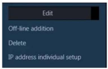
→ The deletion confirmation window will be displayed.

Step 4
Click the [OK] button.
The device information will be deleted.
3.3.3.1.6. Set an IP address of a device (IP address individual setup)
Sets IP addresses of devices displayed in the "Registered device" individually.
Important:
- If the same network segment is set for "Camera/PC port" and "Maintenance port" of a recorder when setting an IP address of the recorder, connection to the recorder from this software will become impossible. Set an IP address of a different network segment from the one that is set for "Maintenance port" of the recorder. Refer to the operating instructions of the recorder in use for "Camera/PC port" and "Maintenance port". • The IP address of the device registered using the host name cannot be changed.
Note:
- [IP address individual setup] can be set only for NX-series and cameras whose validation period set by "Easy IP Setup" is not expired.
- Refer to the operating instructions of the camera in use for the validation period set by "Easy IP Setup".
- To set the IP address of a device not registered in this software, input the "User name" and "Password" of the device on the device edit window in advance. Refer to "Edit the device information".
Step 1
Click the [Device setup] button and then click the [Advanced setup] button to display "Step1 Device detection".
Step 2
Put a check mark on the check box of a device whose IP address is to be set.
Step 3
Click and select [IP address individual setup] from the pull-down menu at the lower right of the window.

The IP address individual setup window will be displayed.
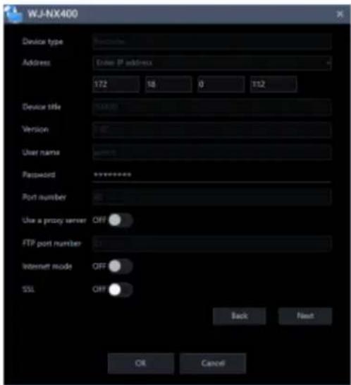
The details of the window are as follows.
■ Device type
Device type will be displayed.
One of camera/ recorder/ microphone/ encoder will be displayed.
■ IP address
When not using the DHCP function, enter an IP address of a device.
Do not enter an IP address that is already set for a PC or other network cameras.
Note:
• Even when using the DHCP function, it is impossible to use multiple IP addresses. - Contact the network administrator for how to configure the DHCP server.
■ Device title
Device title will be displayed.
■ Version information
Firmware version of a device will be displayed. If "Connection check" is not yet executed, the field will be displayed in blank.
■ User name
User name of a device will be displayed.
■ Password
The device password will be displayed with black dots (●).
■ Port number
A port number will be displayed.
■ Use a proxy server
Indicates whether to use a proxy server to connect with devices.
■ FTP port number
An FTP port number will be displayed.
■ Internet mode
Internet mode will be displayed.
■ SSL
Select "ON" or "OFF" to determine whether to execute SSL communication.
ON: Execute SSL communication.
OFF: Do not execute SSL communication.
Default: OFF
Note:
• This setting is valid only when the camera or NX-series is selected as the device type. • This setting is invalid when a recorder other than NX-series is selected as the device type.
■ [Back] button
Shifts to an item above the currently selected item among the items whose check box is checked in the "Registered device".
■ [Next] button
Shifts to an item below the currently selected item among the items whose check box is checked in the "Registered device".
■ [OK] button
Saves the edited contents and displays them in the “Registered device”, and then closes the IP address individual setup window.
■ [Cancel] button
Cancels to save the edited contents and displays them in the "Registered device", and then closes the IP address individual setup window.
Step 4
Click the [OK] button after editing the information.
→ The IP address individual setup window will close.
Important:
- After clicking the [OK] button, it takes about 2 minutes to reflect the IP address on the device. Please do not operate the device during that time. • If you changed the IP address of the device registered in this software, please register the device again.
3.3.3.1.7. Connection check of a device
Checks if the device whose check box in the "Device list" is checked is connected to the network or not, and performs device user authentication.
Also updates the setting values of the "Device list" to the values acquired from devices.
The [Connection check] button is only available when an unregistered device is selected.
Important:
- Note that the settings such as the registration setup will be reset when the setting values are acquired.
- Depending on the communication environment and the state of the target device, device connection may fail.
Step 1
Click the [Device setup] button and then click the [Advanced setup] button to display "Step1 Device detection".
Step 2
Put a check mark on the check box of a device that "Connection check" is to be executed.
Step 3
Click the [Connection check] button.
→ The acquisition progress window will be displayed and acquisition of information of the connected device will start.
If the [Connection check] button is clicked with an already registered device selected, the following warning window will be displayed.

Step 4
When the device information acquisition is completed, the acquisition progress window will close. The update of the setting values of the device will start. Click the [Next] button and shift to “Step2 Camera registration”.
3.3.3.2. Step2 Camera registration
Associates the cameras, microphones and encoders detected on the "Step1 Device detection" window with recorders.
Enter information and click the [Next] button.
→ Shifts to "Step3 Recording setup".

The details of the window are as follows.
■ Search field
Searches for a device title from the camera list.
■ Camera list
Cameras that can be registered in a recorder will be displayed in list form.
Drag a device to be registered and drop onto "Device list".
■ Device list
Recorders, registered cameras and cameras that can be registered in a recorder will be displayed in tree format.
The details of the icons are as follows.

: Device folder → Camera and recorder will be displayed in tree format.
: Recorder folder → Recorder will be displayed in tree format.
: Independent camera folder → Independent cameras will be displayed in tree format.


Note:
- Cameras that are already registered will be displayed with blue background. • It is possible to register the same camera in multiple recorders.
- If there is no available channel on all recorders (reached the recorder registration limit), association will not be executed.
- When right-clicking on a recorder in the device list, the pop-up menu [Delete all] will be displayed. When [Delete all] is selected, all cameras associated with the right-clicked recorder will be deleted from the device list.
- When right-clicking on a camera in the device list, the pop-up menu [Delete] will be displayed. When [Delete] is selected, the right-clicked camera will be deleted from the device list.
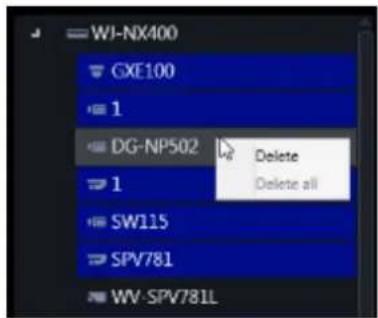
- When dragging a camera in the camera list and dripping onto a recorder in the device list, the camera will be associated with the first available channel of the recorder.


- When dragging a camera in the camera list and dripping onto "Independent camera folder" in the device list, the camera will be registered as an independent camera.


- When Fisheye camera is set to "4 stream mode", link each camera channel one by one.
- When Multi-sensor camera, link each camera one by one.
- Cameras set to "Cropping mode" can only register CH1.
■ Preview
A preview image from the camera selected from the "Camera list" or "Device list" will be displayed.
Important:
• A preview image can be displayed only in the following cases.
● In case of receiving live images from a camera that is not registered in a recorder - In case of directly receiving live images from a camera registered in a recorder, not through the recorder ● In case of acquiring live images via ND400 or NX-series
- When using a recorder other than ND400 and NX-series and selecting [Recorder] for [Live image source], the preview display is unavailable.
- If the camera does not support this software (“Compatible cameras”), such as the ONVIF connection camera, the preview image will not be displayed.
- In the case of Fisheye camera, the preview image becomes fish-eye display irrespective of the setting.
■ [Camera detail setup] button
Configure the detail settings of the camera selected from [Device list]. Refer to "Camera detail setup window" for further information.
■ [Back] button
Shifts to the "Step1 Device detection" window.
■ [Next] button
Shifts to the “Step3 Recording setup” window to configure the recording settings of the item selected from [Device list].
3.3.3.2.1. Camera detail setup window
Configure the detail settings of a camera.
Important:
• Depending on the device, setting functions not supported may be displayed. • Refer to the operating instructions of the device for further information about each setting item. - Items that cannot be set from this software are displayed in blank. - Settings that cause inconsistency on the device side are not reflected on the device. - When using V-series camera, change of the settings is unavailable. - Since the multi-sensor camera is not compatible with the setting change function of this software, some items are grayed out.
Step 1
Select a camera to be edited from [Device list] of "Step2 Camera registration".

Step 2
Click the [Camera detail setup] button.
→ The "Camera detail setup" window will be displayed.

The details of the window are as follows.
■ Check box
Select an operation target camera.
- Address
Address of a camera will be displayed.
■ Port number
A Port number of a camera will be displayed.
■ Model no.
Model number of a camera will be displayed in this area.
■ Camera title
Enter the camera title. The entered camera title will be displayed on the multi-screen window.
Available number of characters: 0 - 20 characters
Unavailable characters: " &
■ Character display in screen
Select "ON" or "OFF" to determine whether to display the character string set by "In-screen character" on the screen or not.
When "ON" is selected, the character string entered for "In-screen character" will be displayed at the position selected in [Display position].
Default: ON
■ In-screen character
Enter a character string to be displayed in the screen.
Available number of characters: 0 - 16 characters
Available characters: Depends on device. Refer to the instruction manual of device.
Default: None (blank)
Note:
- Both a semi-sonant mark and a sonant mark of kana characters will be handled as 1 individual character.
■ Date display
Select a date display format from 24h/12h/OFF.
To not display date and time, select "OFF".
Default: 24h
■ In-screen character position
Select a display position where date and time and the character string are to be displayed in the screen where live images are being displayed.
Upper left: They will be displayed at the upper left of the screen.
Lower left: They will be displayed at the lower left of the screen.
Upper center: They will be displayed at the upper center of the screen.
Lower center: They will be displayed at the lower center of the screen.
Upper right: They will be displayed at the upper right of the screen.
Upper right: They will be displayed at the lower right of the screen.
Default: Upper left
Important:
- When using a camera that does not support "Upper center" and "Lower center" for "In-screen character position", setting at "Upper center" and "Lower center" is unavailable.
■ Image capture mode
Set an image capture mode.
Important:
- For cameras that have been registered with this software or recorder, this setting cannot be selected.
- Image capture mode can be selected only for Fisheye cameras or 4K cameras. For other cameras it will be blank.
- After changing the “Image capture mode”, the changed camera moves from the “Device list” to the “Camera list”.
< In case of Fisheye camera >
Double Panorama
Panorama
Quad PTZ
Single PTZ
Fisheye
Fisheye+Double Panorama (In case of 3M fisheye camera, it will be hidden)
Fisheye+Panorama (In case of 3M fisheye camera, it will be hidden)
Fisheye+Quad PTZ
Quad streams
< In case of 4K camera >
Cropping
OFF
Note:
- 4-Stream mode is a function that corrects distortions in images at 4 points of a fisheye image and cuts out 4 images from them and then displays these 4 of 4:3 images as H.264 and H.265 images by assigning them to each stream number. To activate this mode, it is necessary to select "Quad streams" for the image capture mode of the camera in use.
- The "Cropping mode" is the function to display four cropping images out of panorama image in the ratio of 16:9, and allocate them to each stream number to display in the H.264, H.265 or JPEG format. To activate this mode, it is necessary to select "Cropping 16:9 " for the image capture mode of the camera in use.
■ Stream (1)/(2)/(3)/(4) resolution
Set the resolution of H.264, H.265 or MPEG-4 image of each stream from the following.
Selectable resolution varies depending on the camera and the compression method.
160x120[4:3] / 320x240[4:3] / 400x300[4:3] / 640x480[4:3] / 800x600[4:3] / 1280x960[4:3] /
2048x1536[4:3] / 2560x1920[4:3] / 4000x3000[4:3] / 160x90[16:9] / 320x180[16:9] / 640x360[16:9] / 1280x720[16:9] / 1920x1080[16:9] / 2560x1440[16:9] / 3840x2160[16:9] / 320x320[1:1] / 640x640[1:1] / 1280x1280[1:1] / 2048x2048[1:1] / 2192x2192[1:1] / 2816x2816[1:1] / 2992x2992[1:1] / 360x640[9:16] / 720x1280[9:16] / 1080x1920[9:16] / 1440x2560[9:16] / 2160x3840[9:16]
Important:
- When connection of a camera to be set is already checked, for the image capture size of each stream, the value set by camera will be displayed as default.
- Only the initial value can be selected for “Stream (2)/(3)/(4) resolution” until “Stream (1) resolution” is changed.
- When “Stream (1) resolution” is changed, only the resolution in the same image capture mode as the selected resolution for “Stream (1) resolution” can be selected for “Stream (2)/(3)/(4) resolution”.
- Depending on the camera's model number, resolution and compression method, it may be impossible to change the resolution.
- In the case of a camera with a recorder registered, the recorder may change the resolution of the camera, so a value different from the resolution selected in this setting may be set.
■ Stream (1)/(2)/(3)/(4) distribution mode
Select an H.264/H.265 image transmission mode from the following.
Constant bit rate
Frame rate
Best effort
Advanced variable bit rate
Variable bit rate
Default: Frame rate
Important:
- For H.265 compatible cameras, "Advanced variable bit rate" can not be selected.
■ Stream (1)/(2)/(3)/(4) maximum bit rate (at the time of a burst)
Select an acceptable level from the following for H.264/H.265 bit rate to exceed "Bit rate per client".
High/ Middle/ Low
Default: Low
■ Stream (1)/(2)/(3)/(4) control period (variable bit rate)
Select a period of time to control H.264/H.265 bit rate from the following. Stream will be transmitted while making an average of transmission amount in the selected period is equivalent to the bit rate set in "Bit rate per client".
1h/ 6h/ 24h/ 1week
Default: 24h
■ Stream (1)/(2)/(3)/(4) bit rate per client
Select an H.264/H.265 bit rate per client from the following.
64kbps*/ 128kbps*/ 256kbps*/ 384kbps*/ 512kbps*/ 768kbps*/ 1024kbps*/ 1536kbps*/ 2048kbps*/
3072kbps*/ 4096kbps*/ 6144kbps*/ 8192kbps*/ 10240kbps*/ 12288kbps*/ 14336kbps*/ 16384kbps*
Default: 1024kbps*
* Available range of bit rate varies depending on the set resolution.
In case of QVGA, VGA, 320×180, 640×360: 64kbps - 4096kbps*
In case of 800×600: 128kbps* - 4096kbps*
In case of 1280×960, 1280×720: 256kbps* - 8192kbps*
In case of 1920×1080: 512kbps* - 14336kbps*
In case of 1280×720, 2048×1536: 1024kbps* - 16384kbps*
Important:
• Depending on camera settings, the bit rate may not be displayed.
■ Refresh interval
Select a refresh interval (I-frame interval: 0.2 - 3 seconds) of H.264/H.265 images from the following. If frequently errors occur in the network environment, image disturbance can be reduced by setting the refresh interval shorter.
However, image refresh speed may become slower.
0.2s/ 0.5s/ 1s/ 2s/ 3s
Default: 1s
Important:
- When the setting transmission is performed from this software, all "Refresh interval" of stream 1 - 4 of the camera will become the same.
■ Upside-down
Set the installation method of a camera.
Off (ceiling) / On (desktop) / Wall
Default: Off (ceiling)
Important:
- For H.265 compatible cameras and fisheye cameras with the "Image rotation" function, this setting cannot be selected.
- Upside down may be reversed in some models.
■ Image rotation
Set whether or not to rotate the image (JPEG, H.265, or H.264).
0° (Off): Does not rotate the image.
90°: Rotates the image by 90 degrees.
180° (Upside-down): Turns the image upside down.
270°: Rotates the image by 270 degrees.
Default: 0° (Off)
Important:
- If the camera in use does not have the "Image rotation" function, this setting cannot be selected.
- When the aspect ratio of the resolution selected for "Stream (1) resolution" is "4:3" or "16:9", "90°" and "270°" are unavailable.
- When the aspect ratio of the resolution selected for "Stream (1) resolution" is "9:16", "0° (OFF)" and "180° (Upside-down)" are unavailable.
■ Pan/tilt-flip
Adjust (pan/tilt) the horizontal/vertical position of images by clicking the pad and the buttons.
Select "ON" or "OFF" to determine whether to automatically turn images upside down when the tilt angle reaches a certain degree.
(Digital flip function)
ON: Enable the digital flip function.
OFF: Disable the digital flip function.
Default: OFF
Important:
- This setting can be selected only when the camera is BB-SC364, BB-SW374, BB-SC382, BB-SC384.
■ Super Dynamic (Wide dynamic range)
Select "ON" or "OFF" to determine whether to activate the Super Dynamic function.
ON(High): Activate the Super Dynamic function. When "ON (High)", the contrast is emphasized and the gradation is corrected.
ON(Normal): Activate the Super Dynamic function. When "ON (Normal)", sensitivity is emphasized and gradation is corrected.
OFF: Stop the Super Dynamic function.
Default: OFF
Note:
- Cameras that have the Super Dynamic function or the Wide Dynamic Range function support the Super Dynamic function. The mode set for each camera is different.
- The Super Dynamic function is supported only when the camera direct reception is selected at the time of recorder registration.
■ Adaptive black stretch
Select "ON" or "OFF" to determine whether to activate the dark area correction function.
If "ON" is selected for "Super Dynamic", this setting will become unavailable.
When the dark area correction function is activated, it is possible to make dark areas brighter by the digital image processing.
ON: Activate the dark area correction function.
OFF: Deactivate the dark area correction function.
Default: OFF
Important:
• This setting cannot be set with some H.265 compatible cameras.
■ Indicator
Select how to light on/off the LINK indicator, the ACCESS indicator and the STATUS indicator.
Light (all the time): All indicators will light according to the status.
Light (access): Only the STATUS indicator will light when images are being monitored.
OFF: All indicators will go off.
Default: ON (all the time)
■ Back light compensation (BLC)
Select "On" or "OFF" to determine whether to activate the back light compensation function.
If "ON" is selected for "Super Dynamic", this setting will become unavailable.
The back light compensation function compensates back light by setting a brighter area in images as a mask area.
ON: Mask area will automatically be set.
OFF: Mask area will not automatically be set. It is necessary to set mask area manually.
Default: OFF
■ Light control mode
Select a light amount control mode from the following.
Outdoor: Control light amount using the electronic shutter and the auto focus function depending on the brightness (illuminance). Select this when capturing a bright object outdoor. Note that flickers may sometimes occur under fluorescent lamps.
Flickerless (50Hz) / Flickerless (60Hz): Flickers caused by fluorescent lamps will automatically be corrected properly be used between 50Hz and 60Hz according to the area.
Default: Outdoor
■ Auto slow shutter (Maximum shutter)
The auto slow shutter adjusts the storage time of the sensor and boosts the electronic sensitivity. The available values are as follows.
OFF (1/30s) / Max. 2/30s / Max. 4/30s / Max. 6/30s / Max. 10/30s / Max. 16/30s
Default: OFF (1/30s)
Important:
- When the slow shutter is set, the frame rate will become lower. Also, noises and white dots (scratch) may sometimes be displayed on the screen.
Note:
- When "Max. 16/30s" is selected, the sensitivity will automatically be increased up to x16.
- If "OFF" is selected for "Gain", this setting will become unavailable.
■ Day & Night (IR / electrical)
Select a method to switch between black/white images and color images from the following.
OFF: Color images will be selected.
ON: Black & white images will be selected.
Auto1 (Normal): Images will automatically be switched between BW images and color images depending on the brightness (illuminance) of images.
Automatically switch to color images when a light source is bright and to BW images when a light source is dark.
Auto2 (IR Light): Select this when using an IR light source at night.
Auto3 (Super Chroma Compensation (SCC)): Select this to keep color images even when a light source is dark. If compared with Auto 1, color images will be kept even under low illuminance because of the Super Chroma Compensation (SCC) function.
Default: Auto1 (Normal)
Note:
• Operation sound may be heard at the time of BW switch, but this is not caused by abnormality. - Since the setting of "Auto 3" uses the color compensation technology, color may be displayed different from the actual object depending on the peripheral light condition.
■ VMD alarm
When motion is detected in the set VMD area, the alarm action will be performed.
VMD stands for "Video Motion Detection".
ON: When motion is detected, alarm action is performed.
OFF: Even if motion is detected, alarm action is not performed.
Default: OFF
Important:
- For the PTZ camera, VMD area is set to "except the preset positions". If you set the VMD area to the preset position in the camera browser last time, it cannot be set correctly from this software. Set it from the camera browser.
- In the case of the Fisheye camera, setting values on the camera side may not be displayed correctly. If necessary, set it from the camera browser.
- When "Function type" of "VMD alarm" is set to "i-VMD" in the camera browser, VMD alarm is invalid regardless of this setting. To enable VMD alarm effectively, be sure to set "Function type" of "VMD alarm" is set to "VMD" in the camera browser. For details, please read the operation manual of the camera.
- If the motion detection area is not set using the camera browser in advance, the area will be set to the entire camera image when this setting is set to "ON" and also the setting transmission is performed. If the motion detection area is already set, the area will not be changed.
■ Detection sensitivity
Set the sensitivity to detect a motion in the area. Sensitivity can be set to each area individually.
The larger the value is, the higher the detection sensitivity becomes. The available values are as follows.
1 (low) - 15 (high)
Default: 8
■ Microphone sensitivity
Set the microphone sensitivity. The smaller the value is, the higher the microphone sensitivity becomes.
The available values are as follows.
0 (high sensitivity) - 5 (low sensitivity)
Default: 3
Step 3
Enter information and click the [OK] button.
→ Close the "Camera setup" window.
3.3.3.3. Step3 Recording setup
Configure the recording settings of cameras and recorders, as well as the detailed settings of recorders.
Enter the information and click the [Next] button.
→ Moves to "Step4 Setup transmission".

The details of the window are as follows.
- Recorder list
Recorders and cameras associated with a recorder are displayed in a tree format.
■ Recording setup list
The independent camera selected from the "Recorder list" or the recording information of the recorder is displayed in a list format.
It is also possible to set recording conditions for each camera.
Refer to "Configure the recording settings" for more information.
■ Schedule/Event
Set recording conditions for schedule recording and event recording.
Refer to "Set recording schedule/event" for more information.
■ [Recorder detail setup] button
Configure the detailed settings of the recorder selected from the [Recorder list].
Refer to "Recorder detail setup" for further information.
- Secure mode
Select "ON" or "OFF" to determine whether to operate the recorder selected from "Recorder list" in the secure mode or not.
ON: Operate in secure mode.
OFF: Not operate in secure mode.
Default: OFF
Note:
- This setting is available only for NX-series registered the secure extension license. Refer to the operating instructions of the recorder. • The "CH" model is not covered by this setting.
■ [Back] button
Shifts to the "Step2 Camera registration" window.
■ [Next] button
Shifts to the “Step4 Setup transmission” window.
3.3.3.3.1. Configure the recording settings
Configure the recording conditions of each recorder.
Important:
• Depending on the device, setting functions not supported may be displayed. • Refer to the operating instructions of the device for further information about each setting item. - When using V-series camera, change of the settings other than “ASM300 camera title”, “Camera type”, “Live image source”, “Compression method”, “Bit rate”, “Stream type”, “Image quality” and “Audio” is unavailable. - Since the multi-sensor camera is not compatible with the setting change function of this software, some items are grayed out. For the cameras registered on the recorder, make settings from "Recorder detailed setup".
Note:
- When entering to the setting item of the first line of "Recording setup list", the same value will be automatically entered for the devices selected by the check box after the second line.
Step 1
Select a device to be configured from "Recorder list" of "Step3 Recording setup".

→ Cameras registered in the selected recorder will be displayed in "Recording setup list" in list form.
| ☐ | Address | Port number | Model no. | Camera title | Camera title for recorder setup | ASM3 |
| 80 | ||||||
| ☒ | 172.18.0.199 | 80 | **-SFN480(1) | SFN480 | 1 SFN480 | 1 SP |
| ☒ | 172.18.0.90 | 80 | **-NP502-1 | NP502 | NP502 | NP5C |
| ☐ | 172.18.13.180 | 80 | **-X6511-1 | X6511 | X6511 | X651 |
The details of "Recording setup list" are as follows.
- Check box
Select an operation target camera.
■ IP address
An IP address of a camera will be displayed.
■ Port number
A Port number of a camera will be displayed.
■ Model no.
Model number of a camera will be displayed in this area.
■ Camera title
Camera title for camera setup will be displayed.
■ Camera title for recorder setup
When using NV200, NV300 or NX-series, enter up to 14 characters for camera title for recorder setup. When using ND400, enter up to 16 characters. Default: Name of the camera registered in the recorder
■ ASM300 camera title
Enter up to 60 characters for camera title for ASM300. Default: Device title in "Device list" of "Step1 Device detection"
Note:
- In the initial state, the device name acquired from the recorder is displayed. The displayed name can be changed.
- If the following characters are used for the camera title on the recorder, they will be replaced with spaces.
! % ^ lt; = gt; @ [] ^ _ |
■ Camera type
Camera type and an icon corresponding to the type will be displayed.
There are 21 types of dome camera 1 - 13, fixed camera 1 - 4, fisheye camera 1 - 3 and aero PTZ camera. Default: Fixed camera 1
Important:
- If the camera type is changed, operation method of the camera and the electronic zoom will be adapted to the newly selected camera type. Please note that there may be possibility that operation of the camera and the electronic zoom don't work correctly.
- When acquiring the camera type from the recorder, some models of cameras may be inoperable if using the RS485 terminal. In this case, change the camera type to "Dome camera 1".
- When an aero PTZ camera is registered in ND400, manually set the camera type to "AeroPTZCamera".
■ Live image source
Select a live image/audio source.
- Recorder:
- It is possible to monitor live images/audio through a recorder.
- It is possible to connect without reducing the number of users who can connect to the camera.
- If the connection of the camera from which the image is being displayed is disconnected, it may take several minutes to detect the disconnection.
- Camera:
- It is possible to monitor live images directly from the camera.
- It is possible to monitor live images even when "OFF" is selected for "LIVE VIDEO" in the setup menu of the recorder.
Since the camera transmits images to both the recorder and the PC, the network load will increase more than when setting "Recorder" for "Live image source".
- Since the camera transmits images to both the recorder and the PC, the network load will increase more than when setting "Recorder" for "Live image source".
- If the connection of the camera from which the image is being displayed is disconnected, it may take several seconds to detect the disconnection.
Default: Camera
Note:
- The "Live image source" setting of all the linked cameras will be changed to "Recorder".
■ Compression
Select a compression method for each camera. The compression method can be selected only when using a camera that supports H.264/H.265 or MPEG-4 and "Camera" is selected for "Live image source".
M-JPEG: Live images will be displayed in the M-JPEG format.
MPEG-4: Live images will be displayed in the MPEG-4 format.
H.264: Live images will be displayed in the H.264 format.
H.265: Live images will be displayed in the H.265 format.
Default: Indicates the setting configured on the recorder.
Refer to the operating instructions of the recorder in use for how to configure the compression type of the camera on the recorder.
Note:
- Multi-sensor camera cannot select M-JPEG even when the live image source is "Camera".
■ Resolution
Resolution of the camera will be displayed. If there are multiple streams, the resolution of "stream 1" is displayed.
■ Smart Coding (Advanced)
Set to determine whether to use the GOP control or not. This is available only when “Frame rate” is set for “Distribution mode” and also “H.265” is set for “Compression”.
ON: The GOP control will not be used.
OFF: It is possible to decrease data volume when motions in the screen are few.
Default: OFF
Important:
- This setting can be set only when the camera in use supports the smart coding function. Refer to operating instructions of the camera for further information.
- The pre-recording function of the recorder will become unavailable for a camera if the smart coding is enabled on the camera.
■ Rate
Select a frame rate of a camera from the following.
1fps/ 3fps/ 5fps/ 10fps/ 15fps/ 30fps/ 60fps
Important:
- When the setting transmission is performed from this software, all "Frame rate" of stream 1 - 4 of the camera will become the same.
Note:
- When "Distribution mode" of "Camera detail setup" is set to "Constant bit rate" or "Best effort", this setting is not reflected to the device.
- When an unavailable frame rate is selected by a batch change, the currently set value will be held.
■ Acquisition resolution (JPEG)
Set a resolution when acquiring images from a camera from this software.
The resolution can be set only when "Camera" is selected for "Live image source" and "M-JPEG" is selected for "Compression".
- AUTO (*1) (*2): When displaying images on 1-/3-/4-/6-screen or the large areas of 7-/10-/13-screen, it is possible to monitor VGA images (640x480) fitting to the display size of each screen pattern.
- When displaying images on a screen other than the above, it is possible to monitor QVGA (320x240) images fitting to the display size of each screen pattern.
- 160×120/160×90: It is possible to monitor images whose resolution is 160×120 (160×90 in the 16:9 mode) fitting to the display size of each screen pattern.
- QVGA: It is possible to monitor images whose resolution is QVGA (320x240) fitting to the display size of each screen pattern.
- QVGA/320x180: It is possible to monitor images whose resolution is QVGA (320x240, 320x180 in the 16:9 mode) fitting to the display size of each screen pattern.
- QVGA/320x180/320x320: It is possible to monitor images whose resolution is QVGA (320x240, 320x180 in the 16:9 mode, 320x320 in the 1:1 mode) fitting to the display size of each screen pattern.
- 400x300: It is possible to monitor images whose resolution is 400x300 fitting to the display size of each screen pattern.
- VGA: Images whose resolution is VGA (640x480) will automatically be fit into the area regardless of the screen pattern.
- VGA/640x360: It is possible to monitor images whose resolution is VGA (640x480, 640x360 in the 16:9 mode) fitting to the display size of each area.
- VGA/640×360/800×600: It is possible to monitor images whose resolution is VGA (640×480, 640×360 in the 16:9 mode, 800×600 in the 4:3 (800×600) mode) fitting to the display size of each area.
- VGA/640×360/640×640: It is possible to monitor images whose resolution is VGA (640×480, 640×360 in the 16:9 mode, 640×640 in the 1:1 mode) fitting to the display size of each area.
- 800x600: It is possible to monitor images whose resolution is 800x600 fitting to the display size of each area.
- 1280×960 (*3): It is possible to monitor images whose resolution is 1280×960 fitting to the display size of each screen pattern.
- 1280×960/1280×720: It is possible to monitor images whose resolution is 1280×960 (1280×720 in the 16:9 mode) fitting to the display size of each screen pattern.
- 1280×960/1280×720/1280×1280: It is possible to monitor images whose resolution is 1280×960 (1280×720 in the 16:9 mode, 1280×1280 in the 1:1 mode) fitting to the display size of each screen pattern.
- 1600x1200: It is possible to monitor images whose resolution is 1600x1200 fitting to the display size of each screen pattern.
- 1920×1080 (4*): It is possible to monitor images whose resolution is 1920×1080 fitting to the display size of each screen pattern.
- 2048×1536 (5*) (7*): It is possible to monitor images whose resolution is 2048×1536 fitting to the display size of each screen pattern.
- 2048×1536/2048×2048: It is possible to monitor images whose resolution is 2048×1536 (2048×2048 in the 1:1 mode) fitting to the display size of each screen pattern. • 2192x2192: It is possible to monitor images whose resolution is 2192x2192 fitting to the display size of each screen pattern.
each screen pattern.
- 2560×1920/2560×1440: It is possible to monitor images whose resolution is 2560×1920 (2560×1440 in the 16:9 mode) fitting to the display size of each screen pattern.
- 3072x2304/3072x1728: It is possible to monitor images whose resolution is 3072x2304 (3072x1728 in the 16:9 mode) fitting to the display size of each screen pattern.
- 2816x2816: It is possible to monitor images whose resolution is 2816x2816 fitting to the display size of each screen pattern.
- 2992x2992: It is possible to monitor images whose resolution is 2992x2992 fitting to the display size of each screen pattern.
- 3840x2160: It is possible to monitor images whose resolution is 3840x2160 fitting to the display size of each screen pattern.
- 4000x3000: It is possible to monitor images whose resolution is 4000x3000 fitting to the display size of each screen pattern.
*1: When the image capture mode is 2 or 3 mega-pixels, images whose resolution is VGA will be displayed regardless of the screen pattern.
*2: When using a fisheye camera, the display size varies depending on the image capture mode.
- 1-screen/ left area of 3A-screen/ right area of 3B-screen
| Image capture mode Display size | |
| 9M Fisheye 2992×2992 | |
| 8M Fisheye 2816×2816 | |
| 5M Fisheye | 2192×2192 |
| 4M Fisheye 2048×2048 | |
| 3M Fisheye 2048×1536 | |
| 1.3M Fisheye 1280×960 |
- The large area of 2A-screen/ 2B-screen/ 3C-screen/ 4E-screen/ 4-screen/ 5-screen/ 6A-screen/ 7-screen/ 7A-screen/ 10-screen/ 13-screen
| Image capture mode | Display size |
| 9M Fisheye | 1280×1280 |
| 8M Fisheye | 1280×1280 |
| 5M Fisheye | 1280×1280 |
| 4M Fisheye | 1280×1280 |
| 3M Fisheye | 2048×1536 |
| 1.3M Fisheye | 1280×960 |
- Multi-screen other than the above
| Image capture mode Display size | |
| 9M Fisheye 320×320 | |
| 8M Fisheye 320×320 | |
| 5M Fisheye 320×320 | |
| 4M Fisheye 320×320 | |
| 3M Fisheye 2048×1536 | |
| 1.3M Fisheye 320×240 |
*3: When "Partial" is selected for the scan mode of NP100*, the resolution will be set to 960x720. *4: When the image capture mode is other than 2 mega-pixels (16:9), 3 mega-pixels (16:9), 2M Double Panorama (16:9) and 2M Panorama (16:9), images will be displayed in a different resolution from the set resolution or an error may occur. *5: When the image capture mode is other than 3 mega-pixels (4:3) and 3M Fisheye (4:3), images will be displayed in a different resolution from the set resolution or an error may occur. *6: If selected when "3 mega pixel" is set for "Image capture mode" of NP502 or NW502, an error will occur. *7: If selected when "1.3 mega pixel" is set for "Image capture mode" of NP502 or NW502, an error will occur.
Default: "Auto" when "Camera" is selected for "Live image source" and "M-JPEG" is selected for "Compression". In other case it cannot be selected.
Note:
- In the case of a camera with three JPEG distribution resolutions, if an unavailable image capture size for JPEG (1) - (3) of a camera is set, the image capture size set for JPEG (1) will be applied for images.
- In the case of a camera with two JPEG distribution resolutions, if an image capture size that is not available for JPEG (1) or JPEG (2) is set, the one set for JPEG (1) (if JPEG (1) is not available, JPEG (2)) will be applied for images.
■ Acquisition refresh speed (JPEG)
Determine the refresh interval of the camera (number of images to be refreshed per second). The acquisition refresh speed can be set only when "Camera" is selected for "Live image source" and "M-JPEG" is selected for "Compression".
Auto/0.1 ips/0.2 ips/0.3 ips/0.5 ips/1 ips/2 ips/3 ips/ 5 ips/10 ips/15 ips/ALL
When "Auto" is selected, an appropriate value will be applied according to the maximum refresh speed set on the "Performance" page.
When "ALL" is selected, the refresh speed will be set to "30 ips".
Default: "Auto" when "Camera" is selected for "Live image source" and "M-JPEG" is selected for "Compression". In other case it cannot be selected.
Note:
- The actual refresh interval may become slower than the set refresh interval depending on the network environment, the settings of the camera, and the set maximum refresh interval on the "Performance" page.
■ Stream type
Select the stream type to be acquired from the camera from the following.
The stream type can be set only when "Camera" is selected for "Live image source" and "H.264", "H.265" or "MPEG-4" is selected for "Compression".
- AUTO: For 1-screen/2A-screen/2B-screen/3c-screen, and the large area of 3A-screen/3B-screen/5-screen/7-screen, stream 1 will be used. For screens other than the above, stream 2 will be used. When any of 6-series cameras, new 3-series cameras, WV-SPN531, new 5-series cameras, 7-series cameras (4 mega pixel mode), WV-SFN110,
WV-SFV110, WV-SFN130 and WV-SFV130 is used, streams will be used as follows
Stream 2 for 4-/4E-screen and the large areas of 6A-/7-/10-/13-screen
Stream 3 for 6-/9-/16-/25-screen (WV-ASE202 is required) and the small areas of 3A-/3B-/7-/10-/13-screen
Stream 4 for 36-/49-/64-screen (WV-ASE202 is required)
- Stream 1: Stream 1 will always be used.
- Stream 2: Stream 2 will always be used. • Stream 3 (*): Stream 3 will always be used.
- Stream 4 (*): Stream 4 will always be used.
Default: Stream 1
*This setting item will be displayed only when the camera in use is supported.
Important:
- When "Setup transmission" is done from this software to the recorder, all recording streams will be "Stream 1" regardless of the setting of the recorder.
- In this setting, the recorder's recording stream cannot be set. Set the recording stream in the recorder browser after registering the recorder in this software.
Note:
- Refer to the operating instructions of the camera in use for how to configure the settings of each stream.
- When "AUTO" is selected, it is possible to reduce the network bandwidth usage and decrease the CPU load of the PC by configuring the transmission setting for 1-screen in case of "Stream 1" or by configuring the transmission setting for multi-screen in case of "Stream 2", "Stream 3" and "Stream 4".
- Select "Stream 1" when "Quad stream" is selected for the image capture mode of the fisheye camera. When "AUTO" is selected, the video may not be displayed.
■ Authentication
Select the user authentication method. When "Camera" is selected for "Live image source", set the authentication method for this software and the camera. It is not available if the device is not compatible with the Digest authentication. Also, the selected authentication method is to be used for software connection, and it does not affect the device settings. When the recorder authentication method is "Digest or Basic" and the authentication method of the camera registered in the recorder is "Digest", set the authentication method of this software to "Digest".
Digest: Uses "Digest" authentication.
Basic: Uses "Basic" authentication.
Default: Basic
Select "ON" or "OFF" to determine whether to use the HTTP port or the UDP port when receiving H.264/H.265 and MPEG-4 images or audio in case that "Camera" is selected for "Live image source".
ON: Receive H.264, H.265 or MPEG-4 images with audio using the HTTP port.
OFF: Receive H.264, H.265 or MPEG-4 images with audio using the UDP port.
Default: "OFF" when "Camera" is selected for "Live image source"; otherwise, it cannot be selected.
Note:
- This mode is unavailable when a camera in use is RP-NP244, DG-NP244, RP-NP1000, DG-NP1000, RP-NP1004, DG-NP1004, DG-NS202, DG-NS202A, DG-NF282, DG-NW484,
DG-NS950, DG-NW960, DG-NP304, DG-NF302, DG-NT304, or DG-NT314.
- When Internet mode is being used, select "ON" for "Internet mode (over HTTP)" in the camera settings.
■ SSL
Select "ON" or "OFF" to determine whether to execute SSL communication.
ON: Execute SSL communication.
OFF: Do not execute SSL communication.
Default: OFF
Note:
- When a recorder other than the NX-series is designated as the image acquisition destination, this setting becomes invalid.
- When receiving images directly from the cameras, this setting becomes valid.
■ Auto track
Select "ON" or "OFF" to determine whether to use a camera as a target of auto track when "Camera" is selected for "Live image source".
ON: Use as a target of the auto track.
OFF: Not use as a target of the auto track.
Default: --
Note:
- This mode is available only when the camera in use is DG-SC386, DG-SW396/ WV-SW396J, DG-SW396A/ WV-SW396AJ, WV-SC588/ WV-SC588A, WV-SW598J/ WV-SW598AJ, WV-SW397/ WV-SW397A/ WV-SW397J/ WV-SW397NJ/ WV-SW397BJ, WV-SC387/ WV-SC387A, BB-SW374, BB-SC364, WV-X6533LN or WV-S6532LN.
- This mode is disabled when WV-X6533LN/WV-S6532LN is set into the "Insert/Remove SD memory card" mode.
- When "ON" is selected for "Auto track", the "+" mark will be displayed while panning/tilting is being controlled using the WV-CU950 and the lock-on function will work by pressing the [TOP] button. • Auto track is unavailable while panning/tilting is being controlled.
■ Image quality
Select a recording image quality from the following.
NQ/FQ/SF/XF
Default: NQ
Note:
• This setting cannot be selected for devices not subject to setting, such as independent cameras.
■ Audio
Select "ON" or "OFF" to determine whether to simultaneously record audio or not.
ON: Record audio simultaneously.
OFF: Do not record audio simultaneously.
Note:
• This setting cannot be selected for devices not subject to setting, such as independent cameras. - When selecting a network microphone, please select Fisheye camera to be linked with the microphone.
■ AV Time Alignment
Select "ON" or "OFF" to determine whether or not to adjust timing of video and audio when a microphone is used.
ON: The AV time alignment will be executed.
OFF: The AV time alignment will not be executed.
Default: ON
Step 2
Enter information in "Recording setup list" and click the [Next] button.
→ The recording setup will be completed and the display will shift to "Step 4 Setup transmission".
Set recording schedule/event 3.3.3.3.2.
Set recording conditions for the schedule recording and the event recording of each recorder.
Important:
- In this screen, only the setting equivalent to timetable 1 of schedule 1 is displayed, among the recording schedules of the recorder.
- When recording settings using a schedule other than timetable 1 of schedule 1 are performed, they cannot be set from this screen.
- To set the recording settings for timetable 2, schedule 2 or later, please go to "Recorder detail setup".
Step 1
Select a recorder to be configured from the "Recorder list" in "Step 3 Recording setup".

Step 2
Enter information in "Schedule/Event".

The details of the window are as follows.
■ Day to record
Select the days of the week when recording is to be executed. Put check marks on the days of the week when recording is to be executed.
■ Event recording
• Event recording duration:
Select a recording duration when an event recording is activated.
• Pre-event recording duration:
The pre-event recording is a function that records images before an event occurrence.
Select a pre-event recording duration when an event recording is activated.
■ Total bit rate
A total bit rate of images to be recorded in a recorder will be displayed.
■ Schedule to record

- Schedule recording:
The schedule recording is a function that automatically starts/ends recording of images/audio in the time zone set in advance. Up to 3 time zones can be set for recording.
- Event recording:
The event recording is a function that automatically starts recording of images/audio at an event occurrence. Up to 3 time zones can be set for event recording.

Up to 6 time zones for recording can be set.
Determine whether to perform the schedule recording or event recording for each time zone.
[Schedule recording]
Determine whether to perform the schedule recording in the selected time zone.
ON: Performs the schedule recording.
OFF: Does not perform the schedule recording.
[Event recording]
Determine whether to perform the event recording in the selected time zone.
Recording will not be performed in the not-selected time zone even at an alarm occurrence.
ON: Performs the event recording.
OFF: Does not perform the event recording.
■ [Recorder detail setup] button
Display the "Recorder setup" page. Refer to "→ Recorder detail setup" for further information.
Step 3
Click the [Next] button.
→ The recording schedule/event setup will be completed and the display will shift to "Step 4 Setup transmission".
Recorder detail setup 3.3.3.3.3.
Configure the detail settings of a recorder.
Important:
- The "Recorder detail setup" window can be displayed only NV300, ND400 and NX-series recorder whose "Connection check" was taken. • Depending on the device, setting functions not supported may be displayed.
- Even if the settings for a camera having no license and the business intelligence setting is specified, they will not be applied to the device. • Camera settings exceeding the number of licenses are not set on the device. • Refer to the operating instructions of the device for further information about each setting item.
Step 1
Click a recorder to be configured from "Recorder list" of "Step 3 Recording setup".
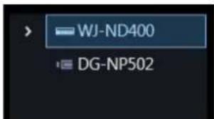
Step 2
Click the [Recorder detail setup] button.
→ The "Configure Recorders" window will be displayed.

Important:
• Refer to the operating instructions of the device for further information about each setting item.
Step 3
Enter information and click the [×] button of the window.
→ The confirmation window will be displayed.

Step 4
Click the [Yes] button.
→ The set contents will be saved and the confirmation window will close.
Note:
- Note that the contents displayed on the recording setup window and on the recorder setup window are different.
- Note that "Schedule recording" and "Event recording" will be displayed in items of the following programs 1 - 3 in case of the recorder setup of ND400. Program 1: Schedule recording individual section Program 2: Event recording individual section Program 3: Schedule/Event recording combined section Program 1: Schedule recording individual section Program 2: Event recording individual section Program 3: Schedule/Event recording combined section
Example case:
"Recording setup" window of ASM300
< Schedule recording > ① 9:00AM - 5:00PM < Event recording > ① 12:00PM - 1:00PM ② 5:00PM - 12:00AM ③ 12:00AM - 9:00AM

< Time only for schedule recording >
9:00AM - 12:00PM/1:00PM - 5:00PM
< Time only for event recording >
5:00PM - 12:00AM/12:00AM - 9:00AM
< Time for both of schedule/event >
12:00PM - 1:00PM

"Recorder setup" window (Recorder browser)
Program 1: 9:00AM - 12:00PM/1:00PM - 5:00PM Program 2: 5:00AM - 12:00AM/12:00PM - 9:00PM Program 3: 12:00PM - 1:00PM
3.3.3.4. Step4 Setup transmission
Save the setting information or transmit it to a device.
| ☐ | Model | Address | Port number | MAC address | Device title | Version | Result |
| ✓ | ND200 | 172.18.101.21 | 80 | BC-C3-42-54-AD-C9 | ND200 | 1.01 | |
| ✓ | NV300 | 172.18.101.20 | 80 | 08-00-23-38-AD-FF | NV300 | 1.70 | |
| ✓ | WJ-ND400 | 172.18.0.184 | 80 | 00-80-45-33-F0-2E | ND400 | 5.60 | |
| ✓ | WJ-ND400 | 172.18.0.112 | 80 | BC-C3-42-3C-4F-C2 | ND400 | 1.02 |
Step 1
Put a check mark on the check box of a device, to which the setting values are to be transmitted, in the device list and click the [Setup transmission] button.
The process progress window will be displayed and transmission of the setting values will start.
When applying the settings to this software without transmitting the setting values to the device, click the [Save] button.
Step 2
When the transmission is completed, the process progress window will close.
The search result will be displayed in list form.

The details of the window are as follows.
■ Transmission result list
Information of devices for which the setup was made will be displayed in list form.
| Item | Description |
| Icon | Result of transmission of setting values will be displayed with icons.It will not be displayed when the [Save] button is clicked.✓ : Transmission successful✗ : Transmission failed |
| Check box | Select a transmission target device.Default: (All items check) |
| Model | A device model will be displayed. |
| Address | Address of a device can be set.Default: IP address of a detected device |
| Port number | An Port number of a device will be displayed. |
| MAC address | A MAC address of a device will be displayed. |
| Device title | A title of a device will be displayed. |
| Version | Firmware version of a device will be displayed. |
| Result | If failed to transmit the setting values, the transmission result will be displayed. |
■ [Back] button
Shifts to the "Step3 Recording setup" window.
■ [Save] button
The settings will be applied to this software without transmitting the setting values to the device.
Important:
- To transmit the setting data created by "Offline-addition" to the device, press the [Setup transmission] button.
■ [Setup transmission] button
Transmits the setting values to a device and saves the settings to this software.
3.3.3.5. Register network microphone
A network microphone and a linked camera will be associated and registered in this software.
Important:
- When using the audio function, set "Audio" of [System] - [Drawing and audio setup] to ON in advance.
- For cameras that can be interlocked with the microphone, please read the owner's manual of your camera.
Step 1
Click the [Device setup] button and then click the [Advanced setup] button to display "Step1 Device detection".
Step 2
Click the [Re-detection] button to display a list of the devices connected to the network.
Step 3
Enter the user name and password for the microphone to be registered and the linked camera on "Device list".
The user name and password can be entered from the edit screen. Refer to "Edit the device information" for further information.
Step 4
Check the check box of the device to be registered, and then click the [Connection check] button. Refer to "Connection check of a device" for further information about the connection check.
Step 5
Click the [Next] button.
→ Shifts to "Step2 Camera registration" window.
Step 6
Drag the microphone displayed in "Camera list" and the linked camera and drop them onto "Device list". When registering the microphone and camera as an independent camera, drop them under the camera folder.
When registering the microphone and camera in the recorder, drop them under the desired recorder.
Important:
- Recorders that support use of microphones are NV300 series, NV250 series, ND400, NX400 (version 2.0 or later), NX300 and NX200 (version 1.1 or later). The available functions vary depending on the firmware version of the recorder. Refer to the operating instructions of the recorder for further information.

Step 7
Click the [Camera detail setup] button.
→ Camera detail setup window will be displayed. Refer to "Camera detail setup window" for further
information about the camera detail setup.
Step 8
On the camera detail setup window, set "Microphone sensitivity" of the microphone to be registered to an appropriate value and then click the [OK] button.
→ Camera detail setup window will close.

Step 9
Click the [Next] button.
→ Shifts to "Step3 Recording setup" window.
Step 10
Select the microphone to be registered from "Recorder list".
→ The selected microphone will be displayed in "Recording setup list".
Refer to "Configure the recording settings" for further information about "Recording setup list".
Step 11
Select a camera linked with the microphone for "Audio" of the microphone displayed in "Recording setup list".

Step 12
Set an appropriate value to "AV Time Alignment" of the microphone displayed in "Recording setup list".

Step 13
When recording the microphone audio in the recorder, select a camera that is linked with the microphone from "Recorder list".
→ The selected camera will be displayed in "Recording setup list". → When the microphone is to be linked with an independent camera, proceed to step 15.
Step 14
Set "Audio" of the camera displayed in "Recording setup list" to "ON".

Step 15
Click the [Next] button.
→ Shifts to the “Step4 Setup transmission” window.
Step 16
Click the [Setup transmission] button.
→ Transmits the setting values to a device and saves the setting to this software.
3.3.3.6. Create setting information in off-line environment and send it to device
It is possible to create device setting information in advance in an offline environment.
By sending the created setting information to the device in an online environment, it reflects the setting on the device so that it can be used with this software.
![graph LR A["Off-line environment"] --> B["Online environment"] B --> C["Device"]](/content/2026/06/1353903/images/c5e013754e424971012f05638fb7419418bdff61d8475b82841da09730585456.jpg)
Important:
- The setting information entered in this setting is a setting to be used when this software executes the connection authentication with devices. Note that the settings are not to be sent to devices. • Use a web browser of a device and edit the user name, password, etc. of the device. • Operation when setting other than the procedure described in this manual is not guaranteed.
- The devices added with this setting cannot be used with this software until "Connection check" or "Setup transmission" is performed.
For details on the connection check, refer to "Connection check of a device".
For details on the setup transmission, refer to "Step4 Setup transmission".
Step 1
Click the [Device setup] button and then click the [Advanced setup] button to display "Step1 Device detection".
Step 2
Click and select [Off-line addition] from the pull-down menu at the lower right of the window.

→ The "Off-line addition" window will be displayed.
Step 3
Enter information of the device to be registered and click the [OK] button.
→ The off-line addition window will close and the contents set to "Device list" will be displayed.
Important:
- Input setting information such as model number and address of device accurately. If there is an error in the input, the device setting will fail.
Step 4
Click the [Next] button.
→ Shifts to “Step2 Camera registration” window.
Important:
- Please do not click the [Connection check] button.
- Refer to the “Connection check of a device” for further information about the connection check.
Step 5
Drag the device to be registered from "Camera list" to "Device list" and move.
Also, enter the device settings from the camera detail setup window.
Refer to "Camera detail setup window" for further information about the camera detail setup.
Refer to "Step2 Camera registration" for associating with the recorder and registration as an independent camera.
Step 6
Click the [Next] button.
→ Shifts to “Step3 Recording setup” window.
Step 7
Click the [Next] button.
→ Shifts to the “Step4 Setup transmission” window.
Step 8
Click the [Save] button.
→ Save the setting information entered from STEP1 to STEP7 in this software and complete the creation of the setting information.
Step 9
Move to the environment (online environment) where this software can connect with the device.
Step 10
Click the [Device setup] button and then click the [Advanced setup] button to display "Step1 Device detection".
→ The device added in STEP3 will be displayed. However, the device associated with the recorder will not be displayed.
Step 11
Click the [Next] button.
→ Shifts to “Step2 Camera registration” window.
Important:
- Please do not click the [Connection check] button. After checking the connection, the setting information created will be overwritten with the setting value of the current device.
- Refer to the “Connection check of a device” for further information about the connection check.
Step 12
Drag the device to be registered from "Camera list" to "Device list" and move.
Step 13
Click the [Next] button.
→ Shifts to "Step3 Recording setup" window.
Step 14
Click the [Next] button.
→ Shifts to the “Step4 Setup transmission” window.
Step 15
Click the [Setup transmission] button.
→ Transmits the setting values to a device and saves the setting to this software.
Device setup 3.3.4.
Set up this software and register device.
Important:
- When changing a device, re-acquire device information. Refer to "Replace a device" for further information.
Click the [Device setup] button, and then click the [Device setup] button.

→ The "Device setup" window will be displayed.
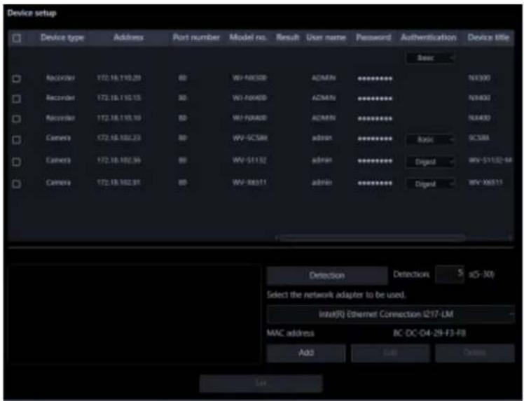
The details of the window are as follows.
■ Device list
Information of devices connected to the network will be displayed in list form.
The setting values of some items can be changed. The display contents are as follows.
| Item | Description |
| Check box | Select an operation target device.Default: (No checked) |
| Icon | Registration status of administrators will be displayed with icons.[SOXO]: Administrator information is already set in device[TAZW]: Administrator information is not yet set in device(Device requires initial registration of administrator)[CVAZ]: Device that is in condition of being uniquely unable to identify the administrator status(Device outside the network segment)* Icons are not displayed for devices registered in this software |
| Device type | Device type will be displayed.One of camera/ recorder/ microphone/ encoder will be displayed. |
| Address | Address of a device will be displayed. |
| Port number | A port number of a device will be displayed. |
| (Recorder icon) | When the failover function of the recorder registered in this software is enabled, the following icons are displayed. It indicates that a recorder having the failover function is monitoring an error. It indicates that a recorder having the failover function is monitoring an error. It indicates that a recorder having the failover function is executing a failover. It indicates that a recorder having the failover function is executing a failover. |
| Model no. | A model number of a device will be displayed. |
| Result | If an error occurred during “Connection check” or “Setup transmission”, an error message will be displayed. |
| User name | Enter the administrator name registered in the device.When nothing is entered (blank), the cell will be displayed in red.Default: (When it is unregistered, nothing (blank) is displayed. When it is registered, a user name will be displayed.) |
| Password | Enter the password for the administrator registered in the device.When nothing is entered (blank), the cell will be displayed in red.Default: (When it is unregistered, nothing (blank) is displayed. When it is registered, the password will be displayed in “●”.) |
| Device title | Enter the title of the device to display with this software 1 - 16 characters. |
| MAC address | A MAC address of a device will be displayed. |
| Version | Firmware version of a device will be displayed after downloading device information. |
| Authentication Select | the user authentication method. It is not available if the device is not compatible with the recorder or the Digest authentication. Also, the selected authentication method is to be used for software connection, and it does not affect the device settings. When the recorder authentication method is “Digest or Basic” and the authentication method of the camera registered in the recorder is “Digest”, set the authentication method of this software to “Digest”.Digest: Uses “Digest” authentication.Basic: Uses “Basic” authentication. |
Note:
- When entering "User name" and "Password" in the first line of the "Device list", the same value will be automatically entered for the devices selected by the check box after the second line.
- When the mouse is moved onto "Device list", the tool tip will appear and display the number of the registered devices.

■ Preview
A preview image from the device selected from the "Device list" will be displayed.
Important:
• A preview image can be displayed only in the following cases. - In case of receiving live images from a camera that is not registered in a recorder - In case of directly receiving live images from a camera registered in a recorder, not through the recorder ● In case of acquiring live images via ND400 or NX-series - When using a recorder other than ND400 and NX-series and selecting [Recorder] for [Live image source], the preview display is unavailable. - If the camera does not support this software (☐ “Compatible cameras”), such as the ONVIF connection camera, the preview image will not be displayed. - In the case of Fisheye camera, the preview image becomes fish-eye display irrespective of the setting.
■ [Detection] button
Detection of devices connected to the network will be executed and detected devices will be displayed in the device list.
Important:
- When using NV200, NV300 or NX-series, connect the camera to the "Camera/PC port". If connected to the "PC port", detection will not be performed. • Refer to the operating instructions of each recorder for further information about the network port.
■ Detection time
Enter a number for the detection time (second) per device.
5 - 30
Default: 5 (s)
■ Network adapter
Select the network adapter to be used for connecting with the device.
■ MAC address
A MAC address of a PC in use will be displayed.
■ [Add] button
The "Device registration" window will be displayed.
Refer to "Register a device individually" for further information.
■ [Edit] button
The "Device registration" window of the device selected in the device list will be displayed.
Refer to "Edit the registered device information" for further information.
■ [Delete] button
The device selected in the device list will be deleted.
Refer to "Delete the registered device information" for further information.
■ [Set] button
The device information of the device selected from the device list will be acquired and the content of the settings will be saved.
3.3.4.1. Detect and register device
Detect devices connected to the network and register them to this software.
When registering a device that is not automatically detected and a device that exists on the different segment, read “Register a device individually”.
Step 1
Click the [Device setup] button and then click the [Device setup] button to display "Device setup" window.

Step 2
Click the [Detection] button.
→ The detection progress window will be displayed and detection of devices connected to the network will start.

When the device detection is completed, the detection progress window will close and the detection results are listed in the device list.

Step 3
Put a check mark on the check box of a device to register.
Step 4
Enter the "User name", "Password" and "Device title" of the checked device.
Step 5
Click the [Set] button.
→ The downloading status window will be displayed. To cancel downloading the device information, click the [Cancel] button on the displayed downloading status window.

Step 6
Click the [OK] button.
→ The settings are saved.

3.3.4.2. Register a device individually
Add a device independently by specifying an address or an HTTP port number.
3.3.4.2.1. Register a recorder individually
Step 1
Click the [Device setup] button and then click the [Device setup] button to display "Device setup" window.

Step 2
Click the [Add] button.
→ The "Device registration" window will be displayed.
Step 3
Click and select [Recorder] from the "Device Type" pull-down menu.
→ The "Device registration" window of the recorder will be displayed.

The details of the window are as follows.
■ Address (Entry type)
Select an entry type of address of a device.
Enter IP address: Specify a device to be registered using IP address.
Enter host name: Specify a device to be registered using FQDN type host name.
Default: IP address enter

■ Address (Entry field)
< When the entry type is "Enter IP address">
Enter the IP address of the device.

Note:
• It is impossible to use IP addresses that are already added.
Enter an FQDN type host name for the device address. Entry shall be up to 255 alphanumeric characters (including hyphens (-) and periods (.)).

Note:
- Entering "http://" is not necessary if the host name is entered.
■ User name
Enter a user name of a device. Enter 1 - 32 alphanumeric characters for user name.
■ Password
Enter a password of a device. The entered password will be displayed with black dots (●). Enter 1 - 32 alphanumeric characters for the password.
Note:
- The "User name" and "Password" that can be registered depend on the device. Refer to the instruction manual of device.
■ Port number
Enter a number among the following for the port number. To turn on "SSL", set port number to 443. 1 - 65535
Default: 80
Note:
- The default HTTP port number set for Video Insight Server is "4011". When using without changing the default, change to "4011" from "80".
■ Use a proxy server
Determine whether to use or not use a proxy server to connect with devices.
ON: Use a proxy server
OFF: Do not use a proxy server
Default: OFF
Important:
- When displaying images directly from cameras, live images will be received without using a proxy server.
■ SSL
Select "ON" or "OFF" to determine whether to execute SSL communication.
ON: Execute SSL communication.
OFF: Do not execute SSL communication.
Default: OFF
Note:
- To turn on SSL, set "port number" to 443.
■ [Download of device information] button
Device information will be downloaded based on entered settings.
■ Model no.
The model number contained in the downloaded device information will be displayed. "Unknown" will be displayed when device information is not downloaded yet.
■ Device title
Enter 1 - 60 characters for the device title.
■ FTP port number
Enter a number among the following for the FTP port number. 1 - 65535 Default: 21
■ Internet mode
Select this item when receiving H.264, H.265 or MPEG-4 images via the Internet. It is possible to transmit H.264, H.265 or MPEG-4 images while maintaining the same setting of the broadband router without changing the setting used for JPEG image transmission. ON: Receive H.264, H.265 or MPEG-4 images with audio using the HTTP port. OFF: Receive H.264, H.265 or MPEG-4 images with audio using the UDP port. Default: OFF
■ [Setup] button
The "Camera setup" window will be displayed. The [Setup] button will be unavailable until recorder information is downloaded.
■ [Set] button
The edited settings will be saved and applied.
■ [Cancel] button
The edited settings are not saved and are discarded.
Step 4
Enter the "Address", "User name", "Password", "Port number", "Use a proxy server" and "SSL".
Step 5
Click the [Download of device information] button.
Important:
- Before acquiring device information, the camera and the microphone (when it is to be used) must be registered according to the operating instructions of the recorder. When the recorder is not configured correctly, downloading of the recorder information may be impossible.
- When the settings of the setup menu of the recorder are edited, download the recorder information
again.
• The camera and the microphone to be linked to each other must be registered in the same recorder. - When connecting with the NX series recorder, SSL communication will be performed at the time of device information acquisition. Assign both the HTTPS port number (default: 443) and the HTTP port number (default: 80) to the recorder and perform the port forwarding setting on the router.
Step 6
Click the [OK] button.

→ The downloading status window will be displayed. To cancel downloading the device information, click the [Cancel] button on the displayed downloading status window.

Step 7
The message window will be displayed when the download process ends.
- When a camera title on the recorder side is changed on the recorder registered in this software, the change confirmation window will be displayed.

→ When the [OK] button is clicked, the camera title that was set on the recorder side will be overwritten by the camera title that was set by this software and then the acquisition of the device information will be completed.
Note:
- If the following characters are used for the camera title on the recorder, they will be replaced with spaces.
→ When the [Cancel] button is clicked, the device information will be completed without changing the camera title.
- When the acquisition completion window is displayed, click the [OK] button.
→ The confirmation window will close.

- Go to step 8.
The error message window will be displayed.
- Confirm the content of the message indicated in the window.
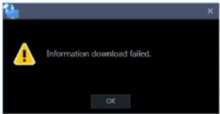
Note:
- Check if the entered device information is correct. When the information has been edited correctly, the connected device or the version of the connected device may not be compatible with this software.
- Click the [OK] button.
→ The error window will close.
- When the device registration will be displayed again, confirm the settings.
- Then, download the device information again.
Step 8
Enter the "Device title", "FTP port number" and "Internet mode".
Step 9
Click the [Setup] button.
→ The "Camera setup" window will be displayed.
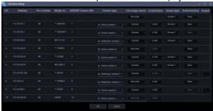
The details of the window are as follows.
Important:
- When using V-series camera, change of the settings other than “Address”, “Port No.”, “ASM300 camera title”, “Live image source”, “Compression method” and “Stream type” is unavailable.
■ CH
The camera channel numbers will be displayed.
■ Address
Address of a device will be displayed.
■ Port number
Port number of a device will be displayed.
■ Model no.
Model number of a device will be displayed.
■ ASM300 Camera title
Enter the device title. The entered device title will be displayed on the multi-screen window. Available number of characters: 0 - 60 characters
Note:
- In the initial state, the device name acquired from the recorder is displayed. The displayed name can be changed.
- If the following characters are used for the camera title on the recorder, they will be replaced with spaces.
! % ^ lt; = gt; @ [] ^ _ |
■ Camera type
Camera type and an icon corresponding to the type will be displayed.
There are 21 types of dome camera 1 - 13, fixed camera 1 - 4, fisheye camera 1 - 3 and aero PTZ camera.
Default: Fixed camera 1
Important:
- If the camera type is changed, operation method of the camera and the electronic zoom will be adapted to the newly selected camera type. Please note that there may be possibility that operation of the camera and the electronic zoom don't work correctly.
- When acquired the camera type from the recorder, some models of cameras may be inoperable if using the RS485 terminal. In this case, change the camera type to "Dome camera 1".
- When an aero PTZ camera is registered in ND400, manually set the camera type to "AeroPTZCamera".
■ Live image source
Select a live image/audio source.
- Recorder:
- It is possible to monitor live images/audio through a recorder.
- It is possible to connect without reducing the number of users who can connect to the camera.
- If the connection of the camera from which the image is being displayed is disconnected, it may take several minutes to detect the disconnection.
- Camera:
- It is possible to monitor live images directly from the camera.
- It is possible to monitor live images even when "OFF" is selected for "LIVE VIDEO" in the setup menu of the recorder.
- Since the camera transmits images to both the recorder and the PC, the network load will increase more than when setting "Recorder" for "Live image source".
- If the connection of the camera from which the image is being displayed is disconnected, it may take several seconds to detect the disconnection.
Default: Camera
Note:
- The "Live image source" setting of all linked cameras will be changed to "Recorder".
■ Compression
Select a compression method for each camera. The compression method can be selected only when using a camera that supports H.264/H.265 or MPEG-4 and "Camera" is selected for "Live image source".
M-JPEG: Live images will be displayed in the M-JPEG format.
MPEG-4: Live images will be displayed in the MPEG-4 format.
H.264: Live images will be displayed in the H.264 format.
H.265: Live images will be displayed in the H.265 format.
Default: Indicates the setting configured on the recorder.
Refer to the operating instructions of the recorder in use for how to configure the compression type of the camera on the recorder.
Note:
• Multi-sensor camera cannot select M-JPEG even when the live image source is "Camera".
■ Stream type
Select the stream type to be acquired from the camera from the following.
The stream type can be set only when "Camera" is selected for "Live image source" and "H.264", "H.265" or "MPEG-4" is selected for "Compression".
• AUTO: For 1-screen/2A-screen/2B-screen/3c-screen, and the large area of
3A-screen/3B-screen/5-screen/7-screen, stream 1 will be used.
For screens other than the above, stream 2 will be used. When any of 6-series cameras, new 3-series cameras, WV-SPN531, new 5-series cameras, 7-series cameras (4 mega pixel mode), WV-SFN110, WV-SFV110, WV-SFN130 and WV-SFV130 is used, streams will be used as follows
Stream 2 for 4-/4E-screen and the large areas of 6A-/7-/10-/13-screen
Stream 3 for 6-/9-/16-/25-screen (WV-ASE202 is required) and the small areas of 3A-/3B-/7-/10-/13-screen
Stream 4 for 36-/49-/64-screen (WV-ASE202 is required)
- Stream 1: Stream 1 will always be used.
- Stream 2: Stream 2 will always be used.
- Stream 3 (*): Stream 3 will always be used.
- Stream 4 (*): Stream 4 will always be used.
Default: Stream 1
*This setting item will be displayed only when the camera in use is supported.
Important:
- In this setting, the recorder's recording stream cannot be set. Set the recording stream in the recorder browser after registering the recorder in this software.
Note:
- Refer to the operating instructions of the camera in use for how to configure the settings of each stream.
- When "AUTO" is selected, it is possible to reduce the network bandwidth usage and decrease the CPU load of the PC by configuring the transmission setting for 1-screen in case of "Stream 1" or by configuring the transmission setting for multi-screen in case of "Stream 2", "Stream 3" and "Stream 4".
■ Authentication
Select the user authentication method. It is not available if the device is not compatible with the recorder or the Digest authentication. Also, the selected authentication method is to be used for software connection, and it does not affect the device settings.
Digest: Uses "Digest" authentication.
Basic: Uses "Basic" authentication.
Default: Basic
■ Acquisition resolution (JPEG)
Set a resolution when acquiring images from a camera from this software.
The resolution can be set only when "Camera" is selected for "Live image source" and "M-JPEG" is selected for "Compression".
- AUTO (*1) (*2): When displaying images on 1-/3-/4-/6-screen or the large areas of 7-/10-/13-screen, it is possible to monitor VGA images (640x480) fitting to the display size of each screen pattern.
- When displaying images on a screen other than the above, it is possible to monitor QVGA (320x240) images fitting to the display size of each screen pattern.
- 160×120/160×90: It is possible to monitor images whose resolution is 160×120 (160×90 in the 16:9 mode) fitting to the display size of each screen pattern.
- QVGA: It is possible to monitor images whose resolution is QVGA (320x240) fitting to the display size of each screen pattern.
- QVGA/320x180: It is possible to monitor images whose resolution is QVGA (320x240, 320x180 in the 16:9 mode) fitting to the display size of each screen pattern.
- QVGA/320x180/320x320: It is possible to monitor images whose resolution is QVGA (320x240, 320x180 in the 16:9 mode, 320×320 in the 1:1 mode) fitting to the display size of each screen pattern.
- 400x300: It is possible to monitor images whose resolution is 400x300 fitting to the display size of each screen pattern.
- VGA: Images whose resolution is VGA (640x480) will automatically be fit into the area regardless of the screen pattern.
- VGA/640x360: It is possible to monitor images whose resolution is VGA (640x480, 640x360 in the 16:9 mode) fitting to the display size of each area.
- VGA/640×360/800×600: It is possible to monitor images whose resolution is VGA (640×480, 640×360 in the 16:9 mode, 800×600 in the 4:3 (800×600) mode) fitting to the display size of each area.
- VGA/640×360/640×640: It is possible to monitor images whose resolution is VGA (640×480, 640×360 in the 16:9 mode, 640×640 in the 1:1 mode) fitting to the display size of each area.
- 800x600: It is possible to monitor images whose resolution is 800x600 fitting to the display size of each area.
- 1280×960 (*3): It is possible to monitor images whose resolution is 1280×960 fitting to the display size of each screen pattern.
- 1280×960/1280×720: It is possible to monitor images whose resolution is 1280×960 (1280×720 in the 16:9 mode) fitting to the display size of each screen pattern.
- 1280×960/1280×720/1280×1280: It is possible to monitor images whose resolution is 1280×960 (1280×720 in the 16:9 mode, 1280×1280 in the 1:1 mode) fitting to the display size of each
screen pattern.
- 1600x1200: It is possible to monitor images whose resolution is 1600x1200 fitting to the display size of each screen pattern.
- 1920×1080 (4*): It is possible to monitor images whose resolution is 1920×1080 fitting to the display size of each screen pattern.
- 2048×1536 (5*) (7*): It is possible to monitor images whose resolution is 2048×1536 fitting to the display size of each screen pattern.
- 2048×1536/2048×2048: It is possible to monitor images whose resolution is 2048×1536 (2048×2048 in the 1:1 mode) fitting to the display size of each screen pattern.
- 2192x2192: It is possible to monitor images whose resolution is 2192x2192 fitting to the display size of each screen pattern.
- 2560×1920/2560×1440: It is possible to monitor images whose resolution is 2560×1920 (2560×1440 in the 16:9 mode) fitting to the display size of each screen pattern.
- 3072x2304/3072x1728: It is possible to monitor images whose resolution is 3072x2304 (3072x1728 in the 16:9 mode) fitting to the display size of each screen pattern.
- 2816x2816: It is possible to monitor images whose resolution is 2816x2816, fitting to the display size of each screen pattern.
- 2992x2992: It is possible to monitor images whose resolution is 2992x2992, fitting to the display size of each screen pattern.
- 3840x2160: It is possible to monitor images whose resolution is 3840x2160, fitting to the display size of each screen pattern.
- 4000x3000: It is possible to monitor images whose resolution is 4000x3000, fitting to the display size of each screen pattern.
*1: When the image capture mode is 2 or 3 mega-pixels, images whose resolution is VGA will be displayed regardless of the screen pattern.
*2: When using a fisheye camera, the display size varies depending on the image capture mode.
- 1-screen/ left area of 3A-screen/ right area of 3B-screen
| Image capture mode | Display size |
| 9M Fisheye | 2992×2992 |
| 8M Fisheye | 2816×2816 |
| 5M Fisheye | 2192×2192 |
| 4M Fisheye | 2048×2048 |
| 3M Fisheye | 2048×1536 |
| 1.3M Fisheye | 1280×960 |
- The large area of 2A-screen/ 2B-screen/ 3C-screen/ 4E-screen/ 4-screen/ 5-screen/ 6A-screen/ 7-screen/ 7A-screen/ 10-screen/ 13-screen
| Image capture mode | Display size |
| 9M Fisheye | 1280×1280 |
| 8M Fisheye | 1280×1280 |
| 5M Fisheye | 1280×1280 |
| 4M Fisheye | 1280×1280 |
| 3M Fisheye | 2048×1536 |
| 1.3M Fisheye | 1280×960 |
- Multi-screen other than the above
| Image capture mode | Display size |
| 9M Fisheye | 320×320 |
| 8M Fisheye | 320×320 |
| 5M Fisheye | 320×320 |
| 4M Fisheye | 320×320 |
| 3M Fisheye | 2048×1536 |
| 1.3M Fisheye | 320×240 |
*3: When "Partial" is selected for the scan mode of NP100*, the resolution will be set to 960x720.
*4: When the image capture mode is other than 2 mega-pixels (16:9), 3 mega-pixels (16:9), 2M Double Panorama (16:9) and 2M Panorama (16:9), images will be displayed in a different resolution from the set resolution or an error may occur.
*5: When the image capture mode is other than 3 mega-pixels (4:3) and 3M Fisheye (4:3), images will be displayed in a different resolution from the set resolution or an error may occur.
*6: If selected when "3 mega pixel" is set for "Image capture mode" of NP502 or NW502, an error will occur.
*7: If selected when "1.3 mega pixel" is set for "Image capture mode" of NP502 or NW502, an error will occur.
Default: "Auto" when "Camera" is selected for "Live image source" and "M-JPEG" is selected for "Compression". In other cases, it cannot be selected.
Note:
- In the case of a camera with three JPEG distribution resolutions, if an unavailable image capture size for JPEG (1) - (3) of a camera is set, the image capture size set for JPEG (1) will be applied for images.
- In the case of a camera with two JPEG distribution resolutions, if an image capture size that is not available for JPEG (1) or JPEG (2) is set, the one set for JPEG (1) (if JPEG (1) is not available, JPEG (2)) will be applied for images.
■ Acquisition refresh speed (JPEG)
Determine the refresh interval of the camera (number of images to be refreshed per second). The acquisition refresh speed can be set only when "Camera" is selected for "Live image source" and "M-JPEG" is selected for "Compression".
Auto/0.1 ips/0.2 ips/0.3 ips/0.5 ips/1 ips/2 ips/3 ips/ 5 ips/10 ips/15 ips/ALL
When "Auto" is selected, an appropriate value will be applied according to the maximum refresh speed set on the "Performance" page.
When "ALL" is selected, the refresh speed will be set to "30 ips".
Default: "Auto" when "Camera" is selected for "Live image source" and "M-JPEG" is selected for "Compression". In other case it cannot be selected.
Note:
- The actual refresh interval may become slower than the set refresh interval depending on the network environment, the settings of the camera and the set maximum refresh interval on the "Performance" page.
Select "ON" or "OFF" to determine whether to use the HTTP port or the UDP port when receiving
H.264/H.265 and MPEG-4 images or audio in case that "Camera" is selected for "Live image source".
ON: Receive H.264, H.265 or MPEG-4 images with audio using the HTTP port.
OFF: Receive H.264, H.265 or MPEG-4 images with audio using the UDP port.
Default: "OFF" when "Camera" is selected for "Live image source"; otherwise, it cannot be selected.
Note:
- This mode is unavailable when a camera in use is RP-NP244, DG-NP244, RP-NP1000, DG-NP1000, RP-NP1004, DG-NP1004, DG-NS202, DG-NS202A, DG-NF282, DG-NW484, DG-NS950, DG-NW960, DG-NP304, DG-NF302, DG-NT304, or DG-NT314.
- When using Internet mode, select "ON" for "Internet mode (over HTTP)" in the camera settings.
■ SSL
Select "ON" or "OFF" to determine whether to execute SSL communication.
ON: Execute SSL communication.
OFF: Do not execute SSL communication.
Default: OFF
Note:
- When a recorder other than NX-series is designated as the image acquisition destination, this setting becomes invalid.
- When receiving images directly from the cameras, this setting becomes valid.
■ Auto track
Select "ON" or "OFF" to determine whether to use a camera as a target of the auto track when "Camera" is selected for "Live image source".
ON: Use as a target of the auto track.
OFF: Not used as a target of the auto track.
Default: --
Note:
- This mode is available only when the camera in use is DG-SC386, DG-SW396/ WV-SW396J, DG-SW396A/ WV-SW396AJ, WV-SC588/ WV-SC588A, WV-SW598J/ WV-SW598AJ, WV-SW397/ WV-SW397A/ WV-SW397J/ WV-SW397NJ/ WV-SW397BJ, WV-SC387/ WV-SC387A, BB-SW374, BB-SC364, WV-X6533LN or WV-S6532LN.
- This mode is disabled when WV-X6533LN/WV-S6532LN is set into the "Insert/Remove SD memory card" mode.
- When "ON" is selected for "Auto track", the "+" mark will be displayed while panning/tilting is being controlled using the WV-CU950 and the lock-on function will work by pressing the [TOP] button. • Auto track is unavailable while panning/tilting is being controlled.
■ Linked camera
When a microphone is used, a channel number of the linked camera contained in the information obtained from the recorder will be displayed.
■ AV Time Alignment
Select "ON" or "OFF" to determine whether or not to adjust timing of video and audio when a microphone is used.
ON: The AV time alignment will be executed.
OFF: The AV time alignment will not be executed.
Default: ON
■ [OK] button
The edited settings will be saved and close the "Camera setup" window.
■ [Cancel] button
The edited settings are not saved and the "Camera setup" window closes.
Step 10
Click the [OK] button after completing the settings.
→ The "Camera setup" window closes.
Note:
- The edited settings will not be saved or applied even when the "Camera setup" window is closed by clicking the [OK] button. To save and apply the settings, click the [Set] button on the "Device registration" window after closing the "Camera setup" window.
Step 11
Click the [Set] button on the "Device registration" window.
→ The "Device registration" window closes and the settings are saved and applied. The registered recorder is displayed in the device list.
3.3.4.2.2. Register a camera individually
Step 1
Click the [Device setup] button and then click the [Device setup] button to display the "Device setup" window.

Step 2
Click the [Add] button.
→ The “Device registration” window will be displayed.
Step 3
Click and select [Camera] from the "Device Type" pull-down menu.
→ The “Device registration” window of the camera will be displayed.
![Device registration Be sure to enter the required information first before clicking the [Download of device information] button. When using a proxy server, configure the "Basic setup" setting under "Communication". Device type Camera Address Enter IP address User name Password Authentication Digest…](/content/2026/06/1353903/images/4b3fc77e368c8e7880d5c60f321a7da1ad84549e48e813340abee472032d4465.jpg)
The details of the window are as follows.
■ Address (Entry type)
Select an entry type of address of a device.
Enter IP address: Specify a device to be registered using IP address.
Enter host name: Specify a device to be registered using FQDN type host name.
Default: IP address enter

■ Address (Entry field)
< When the entry type is "Enter IP address">
Enter the IP address of the device.

Note:
• It is impossible to use IP addresses that are already added.
Enter an FQDN type host name for the device address. Entry shall be up to 255 alphanumeric characters (including hyphens (-) and periods (.)).

Note:
- Entering "http://" is not necessary if the host name is entered.
■ User name
Enter a user name of a device. Enter 1 - 32 alphanumeric characters for user name.
■ Password
Enter a password of a device. The entered password will be displayed with black dots (●). Enter 1 - 32 alphanumeric characters for the password.
Note:
- The "User name" and "Password" that can be registered depend on the device. Refer to the instruction manual of device.
■ Authentication
Select the user authentication method. It is not available if the device is not compatible with the Digest authentication. Also, the selected authentication method is to be used for software connection, and it does not affect the device settings.
Digest: Uses "Digest" authentication.
Basic: Uses "Basic" authentication.
Default: Basic
■ Port number
Enter a number among the following for the port number. To turn on "SSL", set port number to 443. 1 - 65535
Default: 80
■ Use a proxy server
Determine whether to use or not use a proxy server to connect with devices.
ON: Use a proxy server
OFF: Not use a proxy server
Default: OFF
■ SSL
Select "ON" or "OFF" to determine whether to execute the SSL communication.
ON: Execute the SSL communication.
OFF: Not execute the SSL communication.
Default: OFF
Note:
- To turn on SSL, set "port number" to 443.
■ [Download of device information] button
Device information will be downloaded based on entered settings.
■ Model no.
The model number contained in the downloaded device information will be displayed. "Unknown" will be displayed when device information is not downloaded yet.
■ Device title
Enter 1 - 60 characters for the device title.
■ Internet mode
Select this item when receiving H.264, H.265 or MPEG-4 images via the Internet. It is possible to transmit H.264, H.265 or MPEG-4 images while maintaining the same setting of the broadband router without changing the setting used for JPEG image transmission. ON: Receive H.264, H.265 or MPEG-4 images with audio using the HTTP port. OFF: Receive H.264, H.265 or MPEG-4 images with audio using the UDP port. Default: OFF
■ [Setup] button
The "Camera setup" window will be displayed. The [Setup] button will be unavailable until recorder information is downloaded.
■ [Set] button
The edited settings will be saved and applied.
■ [Cancel] button
The edited settings are not saved and are discarded.
Step 4
Enter the "Address", "User name", "Password", "Port number", "Use a proxy server" and "SSL".
Step 5
Click the [Download of device information] button.
Important:
- When the settings of the setup menu of the camera are edited, download the camera information again.
Step 6
Click the [OK] button.

→ The downloading status window will be displayed. To cancel downloading the device information, click the [Cancel] button on the displayed downloading status window.

Step 7
The message window will be displayed when download process ended.
The confirmation window will be displayed.
- Click the [OK] button.
→ The confirmation window will close.

- Go to step 8.
The error message window will be displayed.
- Confirm the content of the message indicated in the window.

Note:
- Check if the entered device information is correct. When the information has been edited correctly, the connected device or the version of the connected device may not be compatible with this software.
- Click the [OK] button.
→ The error window will close.
- When the device registration will be displayed again, confirm the settings.
- Then, download the device information again.
Step 8
Enter the "Device title" and "Internet mode".
Step 9
Click the [Setup] button.
→ When the information has been downloaded from a Fixed camera or a PTZ camera, proceed to Step 10-1. When the information has been downloaded from a Fisheye camera or the camera that support cropping mode, proceed to Step 10-2. When the information has been downloaded from a Multi-sensor camera, proceed to Step 10-3.
Step 10-1
The "Camera setup" window of the Fixed camera or the PTZ camera will be displayed.

The details of the window are as follows.
Important:
- When using V-series camera, change of the settings other than “Camera type”, “Compression method”, and “Stream type” is unavailable.
■ Camera type
Camera type and an icon corresponding to the type will be displayed.
There are 21 types of dome camera 1 - 13, fixed camera 1 - 4, fisheye camera 1 - 3 and aero PTZ camera.
Default: Fixed camera 1
Important:
- If the camera type is changed, operation method of the camera and the electronic zoom will be adapted to the newly selected camera type. Please note that there may be possibility that operation of the camera and the electronic zoom don't work correctly.
■ Compression
Select a compression method for each camera. The compression method can be selected only when using a camera that supports H.264/H.265 or MPEG-4.
M-JPEG: Live images will be displayed in the M-JPEG format.
MPEG-4: Live images will be displayed in the MPEG-4 format.
H.264: Live images will be displayed in the H.264 format.
H.265: Live images will be displayed in the H.265 format.
Default: "H.265" when the camera in use supports the H.265 format. "H.264" when the camera in use supports the H.264 format. When the camera in use is an MPEG-4 camera, the default is "MPEG-4". When the camera in use is not an MPEG-4, H.264 or H.265 camera, the default is "M-JPEG".
■ Stream type
Select the stream type to be acquired from the camera from the following.
The stream type can be set only when "H.264", "H.265" or "MPEG-4" is selected for "Compression".
• AUTO: For 1-screen/2A-screen/2B-screen/3c-screen, and the large area of
3A-screen/3B-screen/5-screen/7-screen, stream 1 will be used.
For screens other than the above, stream 2 will be used. When any of 6-series cameras, new 3-series cameras, WV-SPN531, new 5-series cameras, 7-series cameras (4 mega pixel mode), WV-SFN110, WV-SFV110, WV-SFN130 and WV-SFV130 is used, streams will be used as follows
Stream 2 for 4-/4E-screen and the large areas of 6A-/7-/10-/13-screen
Stream 3 for 6-/9-/16-/25-screen (WV-ASE202 is required) and the small areas of
3A-/3B-/7-/10-/13-screen
Stream 4 for 36-/49-/64-screen (WV-ASE202 is required)
- Stream 1: Stream 1 will always be used.
- Stream 2: Stream 2 will always be used.
- Stream 3 (*): Stream 3 will always be used.
- Stream 4 (*): Stream 4 will always be used.
Default: Stream 1
*This setting item will be displayed only when the camera in use is supported.
Note:
- Refer to the operating instructions of the camera in use for how to configure the settings of each stream.
- When "AUTO" is selected, it is possible to reduce the use of network bandwidth and decrease the CPU load of the PC by configuring the transmission setting for 1-screen in case of "Stream 1" or by configuring the transmission setting for multi-screen in case of "Stream 2", "Stream 3" and "Stream 4".
■ Acquisition resolution (JPEG)
It is the same as the camera setup of the recorder. Refer to "Register a recorder individually".
■ Acquisition refresh speed (JPEG)
Determine the refresh interval of the camera (number of images to be refreshed per second). The acquisition refresh speed can be set only when "M-JPEG" is selected for "Compression".
Auto/0.1 ips/0.2 ips/0.3 ips/0.5 ips/1 ips/2 ips/3 ips/5 ips/10 ips/15 ips/ALL
When "Auto" is selected, an appropriate value will be applied according to the maximum refresh speed set on the "Performance" page.
When "ALL" is selected, the refresh speed will be set to "30 ips".
Default: "Auto" when "Camera" is selected for "Live image source" and "M-JPEG" is selected for
"Compression". In other cases it cannot be selected.
Note:
- The actual refresh interval may become slower than the set refresh interval depending on the network environment, the settings of the camera and the set maximum refresh interval on the "Performance" page.
■ Auto track
Select "ON" or "OFF" to determine whether to use a camera as a target of the auto track when "Camera" is selected for "Live image source".
ON: Use as a target of the auto track.
OFF: Not use as a target of the auto track.
Default: --
Note:
- This mode is available only when the camera in use is DG-SC386, DG-SW396/ WV-SW396J, DG-SW396A/ WV-SW396AJ, WV-SC588/ WV-SC588A, WV-SW598J/ WV-SW598AJ, WV-SW397/ WV-SW397A/ WV-SW397J/ WV-SW397NJ/ WV-SW397BJ, WV-SC387/ WV-SC387A, BB-SW374, BB-SC364, WV-X6533LN or WV-S6532LN.
- This mode is disabled when WV-X6533LN/WV-S6532LN is set into the "Insert/Remove SD memory card" mode.
- When "ON" is selected for "Auto track", the "+" mark will be displayed while panning/tilting is being controlled using the WV-CU950 and the lock-on function will work by pressing the [TOP] button. • Auto track is unavailable while panning/tilting is being controlled.
■ [OK] button
The edited settings will be saved and close the "Camera setup" window.
■ [Cancel] button
The edited settings are not saved and close the "Camera setup" window.
Step 10-2
The "Camera setup" window of the Fisheye camera or the camera that supports cropping mode will be displayed.
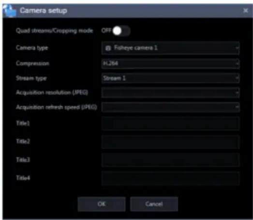
The details of the window are as follows.
Important:
- When using V-series camera, change of the settings other than “Camera type”, “Compression method”, and “Stream type” is unavailable.
■ Quad streams/Cropping mode
Determine whether to use the quad streams or cropping mode.
Quad streams:
4-Stream mode is a function that corrects distortions in images at 4 points of a fisheye image and cuts out 4 images from them and then displays these 4 of 4:3 images as H.264 and H.265 images by assigning them to each stream number. To activate this mode, it is necessary to select "Quad streams" for the image capture mode of the camera in use.
ON: Use the "Quad streams".
OFF: Not to use the "Quad streams".
Cropping mode:
The "Cropping mode" is the function to display four cropping images out of panorama image in the ratio of 16:9, and allocate them to each stream number to display in the H.264 format, H.265 format or JPEG format. To activate this mode, it is necessary to select "Cropping" for the image capture mode of the camera in use.
ON: Use the "Cropping mode".
OFF: Not to use the "Cropping mode".
Default: OFF
■ Camera type
Camera type and an icon corresponding to the type will be displayed.
There are 21 types of dome camera 1 - 13, fixed camera 1 - 4, fisheye camera 1 - 3 and aero PTZ camera.
Default: Fixed camera 1
Important:
- If the camera type is changed, operation method of the camera and the electronic zoom will be adapted to the newly selected camera type. Please note that there may be possibility that operation of the camera and the electronic zoom don't work correctly.
■ Compression
Select a compression method for each camera. The compression method can be selected only when using a camera that supports H.264/H.265 or MPEG-4.
M-JPEG: Live images will be displayed in the M-JPEG format.
MPEG-4: Live images will be displayed in the MPEG-4 format.
H.264: Live images will be displayed in the H.264 format.
H.265: Live images will be displayed in the H.265 format.
Default: "H.265" when the camera in use supports the H.265 format. "H.264" when the camera in use supports the H.264 format. When the camera in use is an MPEG-4 camera, the default is "MPEG-4". When the camera in use is not an MPEG-4, H.264 or H.265 camera, the default is "M-JPEG".
■ Stream type
Select the stream type to be acquired from the camera from the following.
The stream type can be set only when "H.264", "H.265" or "MPEG-4" is selected for "Compression".
• AUTO: For 1-screen/2A-screen/2B-screen/3c-screen, and the large area of 3A-screen/3B-screen/5-screen/7-screen, stream 1 will be used. For screens other than the above, stream 2 will be used. When any of 6-series cameras, new 3-series cameras, WV-SPN531, new 5-series cameras, 7-series cameras (4 mega pixel mode), WV-SFN110, WV-SFV110, WV-SFN130 and WV-SFV130 is used, streams will be used as follows: Stream 2 for 4-/4E-screen and the large areas of 6A-/7-/10-/13-screen; Stream 3 for 6-/9-/16-/25-screen (WV-ASE202 is required) and the small areas of 3A-/3B-/7-/10-/13-screen; Stream 4 for 36-/49-/64-screen (WV-ASE202 is required).
- Stream 1: Stream 1 will always be used. • Stream 2: Stream 2 will always be used.
- Stream 3 (*): Stream 3 will always be used.
- Stream 4 (*): Stream 4 will always be used.
Default: Stream 1
*This setting item will be displayed only when the camera in use is supported.
Note:
- Refer to the operating instructions of the camera in use for how to configure the settings of each stream.
- When "AUTO" is selected, it is possible to reduce the use network bandwidth and decrease the CPU load of the PC by configuring the transmission setting for 1-screen in case of "Stream 1" or by configuring the transmission setting for multi-screen in case of "Stream 2", "Stream 3" and "Stream 4".
■ Acquisition resolution (JPEG)
It is the same as the camera setup of the recorder. Refer to “Register a recorder individually”
■ Acquisition refresh speed (JPEG)
Determine the refresh interval of the camera (number of images to be refreshed per second). The acquisition refresh speed can be set only when "M-JPEG" is selected for "Compression".
Auto/0.1 ips/0.2 ips/0.3 ips/0.5 ips/1 ips/2 ips/3 ips/ 5 ips/10 ips/15 ips/ALL
When "Auto" is selected, an appropriate value will be applied according to the maximum refresh speed set on the "Performance" page.
When "ALL" is selected, the refresh speed will be set to "30 ips".
Default: "Auto" when "Camera" is selected for "Live image source" and "M-JPEG" is selected for "Compression". In other cases, it cannot be selected.
Note:
- The actual refresh interval may become slower than the set refresh interval depending on the network environment, the settings of the camera, and the set maximum refresh interval on the "Performance" page.
■ Title1 - 4
Enter the channel title of each camera. The channel title setting can be changed only when "ON" is selected for "Quad streams/Cropping mode". When editing the channel title, enter 1 - 60 characters.
Default: Channel number
■ [OK] button
The edited settings will be saved and the "Camera setup" window will close.
■ [Cancel] button
The edited settings will not be saved and the "Camera setup" window will close.
Step 10-3
The "Camera setup" window of the multi-sensor camera will be displayed.

The details of the window are as follows.
■ Camera type
Camera type and an icon corresponding to the type will be displayed.
There are 21 types of dome camera 1 - 13, fixed camera 1 - 4, fisheye camera 1 - 3 and aero PTZ camera.
Default: Dome camera 12(Fixed)
Important:
- If the camera type is changed, operation method of the camera and the electronic zoom will be adapted to the newly selected camera type. Please note that there may be possibility that operation of the camera and the electronic zoom don't work correctly.
■ Compression
Select a compression method for each camera. The compression method can be selected only when using a camera that supports H.264/H.265 or MPEG-4.
M-JPEG: Live images will be displayed in the M-JPEG format.
H.264: Live images will be displayed in the H.264 format.
H.265: Live images will be displayed in the H.265 format.
Default: H.265
■ Acquisition resolution (JPEG)
It is the same as the camera setup of the recorder. Refer to "Register a recorder individually"
■ Acquisition refresh speed (JPEG)
Determine the refresh interval of the camera (number of images to be refreshed per second). The acquisition refresh speed can be set only when "M-JPEG" is selected for "Compression".
Auto/0.1 ips/0.2 ips/0.3 ips/0.5 ips/1 ips/2 ips/3 ips/5 ips/10 ips/15 ips/ALL
When "Auto" is selected, an appropriate value will be applied according to the maximum refresh speed set on the "Performance" page.
When "ALL" is selected, the refresh speed will be set to "30 ips".
Default: "Auto" when "Camera" is selected for "Live image source" and "M-JPEG" is selected for
"Compression". In other cases, it cannot be selected.
Note:
- The actual refresh interval may become slower than the set refresh interval depending on the network environment, the settings of the camera, and the set maximum refresh interval on the "Performance" page.
■ Camera 1 – 4 title
Enter the title of camera 1 – camera 4. When editing the camera title, enter 1 - 60 characters.
Default: Channel number
■ Camera 1 – 4 stream type
Select the stream type to be acquired from the camera from the following.
The stream type can be set only when "H.264", "H.265" or "MPEG-4" is selected for "Compression".
- AUTO: For 1-screen/2A-screen/2B-screen/3c-screen, and the large area of 3A-screen/3B-screen/5-screen/7-screen, stream 1 will be used. Stream 2 for 4-/4E-screen and the large areas of 6A-/7-/10-/13-screen. Stream 3 for other areas.
• Stream 1: Stream 1 will always be used.
- Stream 2: Stream 2 will always be used.
Default: Stream 1
Note:
- Refer to the operating instructions of the camera in use for how to configure the settings of each stream.
- When "AUTO" is selected, it is possible to reduce the use of network bandwidth and decrease the CPU load of the PC by configuring the transmission setting for 1-screen in case of "Stream 1" or by configuring the transmission setting for multi-screen in case of "Stream 2" and "Stream 3".
■ [OK] button
The edited settings will be saved and the "Camera setup" window will close.
■ [Cancel] button
The edited settings will not be saved and the "Camera setup" window will close.
Step 11
Click the [OK] button after completing the settings.
→ The "Camera setup" window will close.
Note:
- The edited settings will not be saved and applied even when the "Camera setup" window is closed by clicking the [OK] button. To save and apply the settings, click the [Set] button on the "Device registration" window after closing the "Camera setup" window.
Step 12
Click the [Set] button on the "Device registration" window.
→ The "Device registration" window will close and the settings will be saved and applied. The registered camera will be displayed in the device list.
3.3.4.2.3. Register a microphone individually
Step 1
Click the [Device setup] button and then click the [Device setup] button to display "Device setup" window.

Step 2
Click the [Add] button.
→ The "Device registration" window will be displayed.
Step 3
Click and select [Microphone] from the "Device Type" pull-down menu.
→ The "Device registration" window of the microphone will be displayed.
![Device registration Be sure to enter the required information first before clicking the [Download of device information] button. When using a proxy server, configure the "Basic setup" setting under "Communication". Device type: Microphone Address: Enter IP address User name: Password: Authentication…](/content/2026/06/1353903/images/84f33fe4a06d7033f0c042747f162a87c9256f31b1b8d6f788067262578436cd.jpg)
The details of the window are as follows.
■ Address (Entry type)
Select an entry type of address of a device.
Enter IP address: Specify a device to be registered using IP address.
Enter host name: Specify a device to be registered using FQDN type host name.
Default: IP address enter

■ Address (Entry field)
< When the entry type is "Enter IP address">
Enter the IP address of the device.

Note:
• It is impossible to use IP addresses that are already added.
Enter an FQDN type host name for the device address. Entry shall be up to 255 alphanumeric characters (including hyphens (-) and periods (.)).

Note:
- Entering "http://" is not necessary if the host name is entered.
■ User name
Enter a user name of a device. Enter 1 - 32 alphanumeric characters for user name.
■ Password
Enter a password of a device. The entered password will be displayed with black dots (●). Enter 1 - 32 alphanumeric characters for the password.
Note:
- The "User name" and "Password" that can be registered depend on the device. Refer to the instruction manual of the device.
■ Authentication
Select the user authentication method. It is not available if the device is not compatible with Digest authentication. Also, the selected authentication method is to be used for software connection, and it does not affect the device settings.
Digest: Uses "Digest" authentication.
Basic: Uses "Basic" authentication.
Default: Basic
■ Port number
Enter a number among the following for the port number. To turn on "SSL", set port number to 443. 1 - 65535
Default: 80
■ Use a proxy server
Determine whether to use or not use a proxy server to connect with devices.
ON: Use a proxy server
OFF: Not use a proxy server
Default: OFF
■ SSL
Select "ON" or "OFF" to determine whether to execute the SSL communication.
ON: Execute the SSL communication.
OFF: Not execute the SSL communication.
Default: OFF
Note:
• To turn on SSL, set "port number" to 443.
■ [Download of device information] button
Device information will be downloaded based on entered settings.
■ Model no.
The model number contained in the downloaded device information will be displayed. "Unknown" will be displayed when device information is not downloaded yet.
■ Device title
Enter 1 - 60 characters for the device title.
■ Internet mode
Select HTTP port or UDP port to use for audio reception.
ON: Receive H.264, H.265 or MPEG-4 images with audio using the HTTP port.
OFF: Receive H.264, H.265 or MPEG-4 images with audio using the UDP port.
Default: OFF
■ Linked camera
The title of the linked camera contained in the device information downloaded from the microphone will be displayed. "Not set" will be displayed when device information is not downloaded yet. When the linked camera is to be changed, select a device from the list.
Important:
- For cameras that can be interlocked with the microphone, please read the owner's manual of your camera.
■ AV Time Alignment
Select to determine whether or not to use the AV time alignment.
ON: Use the AV time alignment.
OFF: Not use the AV time alignment.
Default: ON
■ [Setup] button
The "Camera setup" window will be displayed.
The [Setup] button will be unavailable until recorder information is downloaded.
■ [Set] button
The edited settings will be saved and applied.
■ [Cancel] button
The edited settings are not saved and are discarded.
Step 4
Enter the "Address", "User name", "Password", "Port number", "Use a proxy server" and "SSL".
Step 5
Click the [Download of device information] button.
Important:
- When the settings of the setup menu of the microphone are edited, download the microphone information again.
Step 6
Click the [OK] button.

→ The downloading status window will be displayed. To cancel downloading the device information, click the [Cancel] button on the displayed downloading status window.

Step 7
The message window will be displayed when download process ended.
The confirmation window will be displayed.
- Click the [OK] button.
→ The confirmation window will close.

- Go to step 8.
The error message window will be displayed.
- Confirm the content of the message indicated in the window.

Note:
- Check if the entered device information is correct. When the information has been edited correctly, the connected device or the version of the connected device may not be compatible with this software.
- Click the [OK] button.
→ The error window will close.
- When the device registration will be displayed again, confirm the settings.
- Then, download the device information again.
Step 8
Click the [Set] button after editing the information.
→ The "Device registration" window will close and the settings will be saved and applied. The registered microphone will be displayed in the list of the registered devices.
Note:
- When the camera and the microphone are configured to be linked, audio from the microphone will be used. When they are not to be linked, audio from the camera will be used.
- When the camera set as the linked camera is deleted, the setting of the linked camera will automatically return to "Not set". Register the camera again, and then download the microphone information again.
- When "ON" is selected for "Quad streams/Cropping mode" of the linked camera, the linkage setting will automatically be deleted.
3.3.4.2.4. Register an encoder individually
Step 1
Click the [Device setup] button and then click the [Device setup] button to display "Device setup" window.
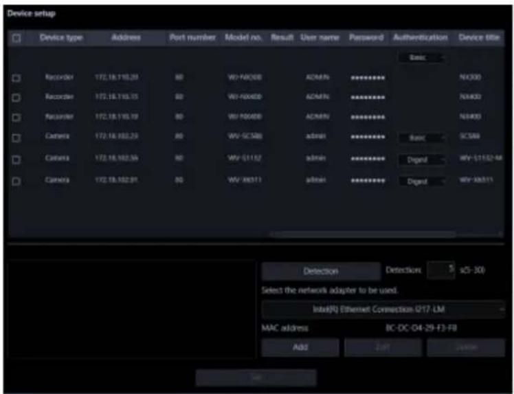
Step 2
Click the [Add] button.
→ The "Device registration" window will be displayed.
Step 3
Click and select [Encoder] from the "Device Type" pull-down menu.
→ The "Device registration" window of the encoder will be displayed.
![Device registration Be sure to enter the required information first before clicking the [Download of device information] button. When using a proxy server, configure the "Basic setup" setting under "Communication". Device type: Encoder Address: Enter IP address User name: Password: Authentication: D…](/content/2026/06/1353903/images/8283bf289280a80ff1053bdc3b616e89cfef022c6b3ec2be561311d4ea666f85.jpg)
The details of the window are as follows.
■ Address (Entry type)
Select an entry type of address of a device.
Enter IP address: Specify a device to be registered using IP address.
Enter host name: Specify a device to be registered using FQDN type host name.
Default: IP address enter

■ Address (Entry field)
< When the entry type is "Enter IP address">
Enter the IP address of the device.

Note:
• It is impossible to use IP addresses that are already added.
Enter an FQDN type host name for the device address. Entry shall be up to 255 alphanumeric characters (including hyphens (-) and periods (.)).

Note:
- Entering "http://" is not necessary if the host name is entered.
■ User name
Enter a user name of a device. Enter 1 - 32 alphanumeric characters for user name.
■ Password
Enter a password of a device. The entered password will be displayed with black dots (●). Enter 1 - 32 alphanumeric characters for the password.
Note:
- The "User name" and "Password" that can be registered depend on the device. Refer to the instruction manual of device.
■ Authentication
Select the user authentication method. It is not available if the device is not compatible with the Digest authentication. Also, the selected authentication method is to be used for software connection, and it does not affect the device settings.
Digest: Uses "Digest" authentication.
Basic: Uses "Basic" authentication.
Default: Basic
■ Port number
Enter a number among the following for the port number. To turn on "SSL", set port number to 443.
1 - 65535
Default: 80
■ Use a proxy server
Determine whether to use or not use a proxy server to connect with devices.
ON: Use a proxy server
OFF: Not use a proxy server
Default: OFF
■ [Download of device information] button
Device information will be downloaded based on entered settings.
■ Device title
Enter 1 - 60 characters for the device title.
■ Internet mode
Select this item when receiving H.264, H.265 or MPEG-4 images via the Internet.
It is possible to transmit H.264, H.265 or MPEG-4 images while maintaining the same setting of the broadband router without changing the setting used for JPEG image transmission.
ON: Receive H.264, H.265 or MPEG-4 images with audio using the HTTP port.
OFF: Receive H.264, H.265 or MPEG-4 images with audio using the UDP port.
Default: OFF
■ [Setup] button
The "Camera setup" window will be displayed.
The [Setup] button will be unavailable until recorder information is downloaded.
■ [Set] button
The edited settings will be saved and applied.
■ [Cancel] button
The edited settings are not saved and are discarded.
Step 4
Enter the "Address", "User name", "Password", "Port number" and "Use a proxy server".
Step 5
Click the [Download of device information] button.
Important:
- When the settings of the setup menu of the encoder are edited, download the encoder information again.
Step 6
Click the [OK] button.

→ The downloading status window will be displayed. To cancel downloading the device information, click the [Cancel] button on the displayed downloading status window.

Step 7
The message window will be displayed when the download process ends.
The confirmation window will be displayed.
- Click the [OK] button.
→ The confirmation window will close.

- Go to step 8.
The error message window will be displayed.
- Confirm the content of the message indicated in the window.

Note:
- Check if the entered device information is correct. When the information has been edited correctly, the connected device or the version of the connected device may not be compatible with this software.
- Click the [OK] button.
→ The error window will close.
- When the device registration will be displayed again, confirm the settings.
- Then, download the device information again.
Step 8
Enter the "Device title" and "Internet mode".
Step 9
Click the [Setup] button.
→ The "Camera setup" window will be displayed.
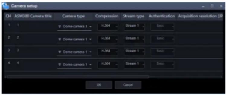
The details of the window are as follows.
■ CH
The camera channel numbers will be displayed.
■ ASM300 Camera title
Enter the device title. The entered device title will be displayed on the multi-screen window. Available number of characters: 1 - 60 characters
■ Camera type
Camera type and an icon corresponding to the type will be displayed.
There are 21 types of dome camera 1 - 13, fixed camera 1 - 4, fisheye camera 1 - 3 and aero PTZ camera.
Default: Fixed camera 1
Important:
- If the camera type is changed, operation method of the camera and the electronic zoom will be adapted to the newly selected camera type. Please note that there may be possibility that operation of the camera and the electronic zoom don't work correctly.
- When acquiring the camera type from the recorder, some models of cameras may be inoperable if using the RS485 terminal. In this case, change the camera type to "Dome camera 1".
- When an aero PTZ camera is registered in ND400, manually set the camera type to "AeroPTZCamera".
■ Compression
Select a compression method for each camera. The compression method can be selected only when using a camera that supports H.264/H.265 or MPEG-4 and "Camera" is selected for "Live image source".
M-JPEG: Live images will be displayed in the M-JPEG format.
MPEG-4: Live images will be displayed in the MPEG-4 format.
H.264: Live images will be displayed in the H.264 format.
Default: "H.264" when the encoder in use supports the H.264 format, "MPEG-4" when the encoder in use does not support the H.264 format.
■ Stream type
Select the stream type to be acquired from the camera from the following.
The stream type can be set only when "Camera" is selected for "Live image source" and "H.264", "H.265" or "MPEG-4" is selected for "Compression".
- AUTO: For 1-screen/2A-screen/2B-screen/3c-screen, and the large area of 3A-screen/3B-screen/5-screen/7-screen, stream 1 will be used. For screens other than the above, stream 2 will be used. When any of 6-series cameras, new 3-series cameras, WV-SPN531, new 5-series cameras, 7-series cameras (4 mega pixel mode), WV-SFN110, WV-SFV110, WV-SFN130 and WV-SFV130 is used, streams will be used as follows: Stream 2 for 4-/4E-screen and the large areas of 6A-/7-/10-/13-screen; Stream 3 for 6-/9-/16-/25-screen (WV-ASE202 is required) and the small areas of 3A-/3B-/7-/10-/13-screen; Stream 4 for 36-/49-/64-screen (WV-ASE202 is required)
- Stream 1: Stream 1 will always be used.
- Stream 2: Stream 2 will always be used.
- Stream 3 (*): Stream 3 will always be used.
- Stream 4 (*): Stream 4 will always be used.
Default: Stream 1
*This setting item will be displayed only when the camera in use is supported.
Note:
- Refer to the operating instructions of the camera in use for how to configure the settings of each stream.
- When "AUTO" is selected, it is possible to reduce the use network bandwidth and decrease the CPU load of the PC by configuring the transmission setting for 1-screen in case of "Stream 1" or by configuring the transmission setting for multi-screen in case of "Stream 2", "Stream 3" and "Stream 4".
■ Acquisition resolution (JPEG)
Set a resolution when acquiring images from a camera from this software.
The resolution can be set only when "M-JPEG" is selected for "Compression".
- AUTO (*1) (*2): When displaying images on 1-/3-/4-/6-screen or the large areas of 7-/10-/13-screen, it is possible to monitor VGA images (640x480) fitting to the display size of each screen pattern.
- When displaying images on a screen other than the above, it is possible to monitor QVGA (320x240) images fitting to the display size of each screen pattern.
- 160×120/160×90: It is possible to monitor images whose resolution is 160×120 (160×90 in the 16:9 mode) fitting to the display size of each screen pattern.
- QVGA: It is possible to monitor images whose resolution is QVGA (320x240) fitting to the display size of each screen pattern.
- QVGA/320x180: It is possible to monitor images whose resolution is QVGA (320x240, 320x180 in the 16:9 mode) fitting to the display size of each screen pattern.
- QVGA/320x180/320x320: It is possible to monitor images whose resolution is QVGA(320x240, 320x180 in the 16:9 mode, 320×320 in the 1:1 mode) fitting to the display size of each screen pattern.
- 400x300: It is possible to monitor images whose resolution is 400x300, fitting to the display size of each screen pattern.
- VGA: Images whose resolution is VGA (640x480) will automatically be fit into the area regardless of the screen pattern.
- VGA/640x360: It is possible to monitor images whose resolution is VGA (640x480, 640x360 in the 16:9 mode), fitting to the display size of each area.
- VGA/640×360/800×600: It is possible to monitor images whose resolution is VGA (640×480, 640×360 in the 16:9 mode, 800×600 in the 4:3 (800×600) mode), fitting to the display size of each area.
- VGA/640×360/640×640: It is possible to monitor images whose resolution is VGA (640×480, 640×360 in the 16:9 mode, 640×640 in the 1:1 mode), fitting to the display size of each area.
- 800x600: It is possible to monitor images whose resolution is 800x600, fitting to the display size of each area.
- 1280×960 (*3): It is possible to monitor images whose resolution is 1280×960, fitting to the display size of each screen pattern.
- 1280×960/1280×720: It is possible to monitor images whose resolution is 1280×960 (1280×720 in the 16:9 mode), fitting to the display size of each screen pattern.
- 1280×960/1280×720/1280×1280: It is possible to monitor images whose resolution is 1280×960 (1280×720 in the 16:9 mode, 1280×1280 in the 1:1 mode), fitting to the display size of each screen pattern.
- 1600x1200: It is possible to monitor images whose resolution is 1600x1200, fitting to the display size of each screen pattern.
- 1920×1080 (4*): It is possible to monitor images whose resolution is 1920×1080, fitting to the display size of each screen pattern.
- 2048×1536 (5*) (7*): It is possible to monitor images whose resolution is 2048×1536, fitting to the display size of each screen pattern.
- 2048×1536/2048×2048: It is possible to monitor images whose resolution is 2048×1536 (2048×2048 in the 1:1 mode), fitting to the display size of each screen pattern.
- 2192x2192: It is possible to monitor images whose resolution is 2192x2192, fitting to the display size of each screen pattern.
- 2560×1920/2560×1440: It is possible to monitor images whose resolution is 2560×1920 (2560×1440 in the 16:9 mode), fitting to the display size of each screen pattern.
- 2816x2816: It is possible to monitor images whose resolution is 2816x2816 fitting to the display size of each screen pattern.
- 2992x2992: It is possible to monitor images whose resolution is 2992x2992 fitting to the display size of each screen pattern.
- 3840x2160: It is possible to monitor images whose resolution is 3840x2160 fitting to the display size of each screen pattern.
- 4000x3000: It is possible to monitor images whose resolution is 4000x3000 fitting to the display size of each screen pattern.
*1: When the image capture mode is 2 or 3 mega-pixels, images whose resolution is VGA will be displayed regardless of the screen pattern.
*2: When using a fisheye camera, the display size varies depending on the image capture mode.
- 1-screen/ left area of 3A-screen/ right area of 3B-screen
| Image capture mode | Display size |
| 9M Fisheye | 2992×2992 |
| 8M Fisheye | 2816×2816 |
| 5M Fisheye | 2192×2192 |
| 4M Fisheye | 2048×2048 |
| 3M Fisheye | 2048×1536 |
| 1.3M Fisheye | 1280×960 |
- The large area of 2A-screen/ 2B-screen/ 3C-screen/ 4E-screen/ 4-screen/ 5-screen/ 6A-screen/ 7-screen/ 7A-screen/ 10-screen/ 13-screen
| Image capture mode | Display size |
| 9M Fisheye | 1280×1280 |
| 8M Fisheye | 1280×1280 |
| 5M Fisheye | 1280×1280 |
| 4M Fisheye | 1280×1280 |
| 3M Fisheye | 2048×1536 |
| 1.3M Fisheye | 1280×960 |
- Multi-screen other than the above
| Image capture mode | Display size |
| 9M Fisheye | 320×320 |
| 8M Fisheye | 320×320 |
| 5M Fisheye | 320×320 |
| 4M Fisheye | 320×320 |
| 3M Fisheye | 2048×1536 |
| 1.3M Fisheye | 320×240 |
*3: When "Partial" is selected for the scan mode of NP100*, the resolution will be set to 960x720. *4: When the image capture mode is other than 2 mega-pixels (16:9), 3 mega-pixels (16:9), 2M Double Panorama (16:9) and 2M Panorama (16:9), images will be displayed in a different resolution from the set resolution or an error may occur. *5: When the image capture mode is other than 3 mega-pixels (4:3) and 3M Fisheye (4:3), images will be displayed in a different resolution from the set resolution or an error may occur. *6: If selected when "3 mega pixel" is set for "Image capture mode" of NP502 or NW502, an error will occur. *7: If selected when "1.3 mega pixel" is set for "Image capture mode" of NP502 or NW502, an error will occur.
Default: "Auto" when "Camera" is selected for "Live image source" and "M-JPEG" is selected for "Compression". In other case it cannot be selected.
Note:
- For 6-series cameras, new 3-series cameras, WV-SPN531, and new 5-series cameras, if an unavailable image capture size for JPEG (1) - (3) of a camera is set, the image capture size set for JPEG (1) will be applied for images.
- For 9M Fisheye cameras and 7-series cameras, if an image capture size that is not available for JPEG (1) or JPEG (2) is set, the one set for JPEG (1) (if JPEG (1) is not available, JPEG (2)) will be applied for images.
■ Acquisition refresh speed (JPEG)
Determine the refresh interval of the camera (number of images to be refreshed per second). The acquisition refresh speed can be set only when "M-JPEG" is selected for "Compression".
Auto/0.1 ips/0.2 ips/0.3 ips/0.5 ips/1 ips/2 ips/3 ips/ 5 ips/10 ips/15 ips/ALL
When "Auto" is selected, an appropriate value will be applied according to the maximum refresh speed set on the "Performance" page.
When "ALL" is selected, the refresh speed will be set to "30 ips".
Default: "Auto" when "Camera" is selected for "Live image source" and "M-JPEG" is selected for "Compression". In other case it cannot be selected.
Note:
- The actual refresh interval may become slower than the set refresh interval depending on the network environment, the settings of the camera and the set maximum refresh interval on the "Performance" page.
■ [OK] button
The edited settings will be saved and close the "Camera setup" window.
■ [Cancel] button
The edited settings are not saved and close the "Camera setup" window.
Step 10
Click the [OK] button after completing the settings.
→ The "Camera setup" window will close.
Note:
- The edited settings will not be saved and applied even when the "Camera setup" window is closed by clicking the [OK] button. To save and apply the settings, click the [Set] button on the "Device registration" window after closing the "Camera setup" window.
Step 11
Click the [Set] button on the "Device registration" window.
→ The "Device registration" window will close and the settings will be saved and applied. The registered encoder will be displayed in the device list.
3.3.4.3. Edit the registered device information
Edit the device information displayed in "Device List".
Step 1
Click the [Device setup] button and then click the [Device setup] button to display "Device setup" window.

Step 2
Click the [Edit] button.
→ The “Device registration” window will be displayed. It is also possible to display the device registration window by double-clicking a device to be edited.
Step 3
Click the [Set] button after editing the information.
→ The "Device registration" window will close and the settings will be saved and applied.
3.3.4.4. Perform a batch update of device information
When the settings are changed on the device side, the device information will be collectively acquired and the registration information will be updated.
Important:
- When a setting including the address of the device, port number, user name or password is changed, update of the registration information in the following procedure is unavailable. In this case, update the registration information by following the procedure described in “Edit the registered device information”.
Step 1
Click the [Device setup] button and then click the [Device setup] button to display "Device setup" window.

Step 2
Put a check mark on the check box of the device whose registration information is to be updated.
Step 3
Click the [Set] button.
→ The downloading status window will be displayed. To cancel downloading the device information, click the [Cancel] button on the displayed downloading status window.

Step 4
When a camera title on the recorder side is changed on the recorder registered in this software, the change confirmation window will be displayed.
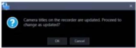
→ When the [OK] button is clicked, the camera title that was set on the recorder side will be overwritten by the camera title that was set by this software. When multiple recorders are selected in step 2, a batch update of the camera titles on the selected recorders will be applied.
Note:
- If the following characters are used for the camera title on the recorder, they will be replaced with spaces.
When the [Cancel] button is clicked, the device information will be completed without changing the camera title.
Step 5
Click the [OK] button.
The settings are saved.

3.3.4.5. Delete the registered device information
Delete the device information displayed in "Device List".
Step 1
Click the [Device setup] button and then click the [Device setup] button to display "Device setup" window.

Step 2
Put a check mark on the check box of a device whose information is to be deleted.
Step 3
Click the [Delete] button.
The confirmation window will be displayed.

Step 4
Click the [OK] button.
→ The device information will be deleted.
3.3.4.6. Replace a device
Change the registered information of an already registered recorder, camera, microphone, or encoder to the information of a device with the same model number and same address. When changing the model number, register data after deleting the registered data. Refer to "Delete a device" for further information.
Step 1
Click the [Device setup] button and then the [Device registration] button to display the "Device registration" window.

Step 2
Select a device to be edited from the device list, and then click the [Edit] button.
→ The "Device registration" window will be displayed.
It is also possible to display the device registration window by double-clicking a device to be edited.
Step 3
Click the [Download of device information] button.
→ The confirmation window will be displayed.

Step 4
Click the [OK] button.
The confirmation window will be displayed if the Model No. and the address of the device to be registered are already registered to this software and the MAC address does not match.
![The information of the device registered to this software has been changed. To overwrite the information, select [OK] and save the setting.](/content/2026/06/1353903/images/ea07664959a779027f0bb8396f20b7c9df750a9b6bed34dfa2c7dc0b2f008130.jpg)
Step 5
Click the [Download of device information] button.
The confirmation window will be displayed.
Step 6
Click the [Set] button after editing the information.
Refer to the "Add a device individually" section for further information about each item.
The "Device registration" window will close and the settings will be saved and applied.
Important:
- Even when the confirmation window is closed by clicking the [OK] button in STEP 5, the settings will not be saved. Click the [Set] button on the "Device registration" window after closing the confirmation window.
- If the channel information is changed or a camera is deleted before or after replacement of a recorder, the folder, group, sequence or map's camera information will be deleted.
3.3.5. External device connection
Click the [Device setup] button and then click the [External device] button to display "External device setup" window.
Configure the settings in order to connect to an external device.
Important:
- The submenu [External device] will not be displayed unless the license of the extension software WV-ASE204 is registered.

3.3.5.1. System Integration
This setting will be displayed only when the license of the extension software WV-ASE204 is added.
Click the [System Integration] tab to display the system integration window.
Configure the settings relating to the integration between this software and other system.
Add a decoder 3.3.5.1.1.
Step 1
Click the [Decoder] tab to display the registered device window.

The details of the window are as follows.
■ Registered device
Titles, model numbers and addresses of the registered decoders will be displayed in list form.
■ Number of registration
Number of the registered decoders will be displayed.
■ [Add] button
Displays the "Device registration" window.
■ [Edit] button
Displays the "Device registration" window of the decoder selected from the device list.
■ [Delete] button
The decoder selected from the list will be deleted.
Step 2
Click the [Add] button.
→ The "Device registration" window will be displayed.

The details of the window are as follows.
■ Address
Enter the IP address of the decoder. Enter an address using up to 255 alphanumeric characters including “.” (period) and “-” (hyphen)
■ Port number
Enter a number among the following for the Port number.
1 - 65535
Default: 80
■ Use a proxy server
Determine whether to use a proxy server to connect the decoder or not.
ON: Use a proxy server
OFF: Not use a proxy server
Default: OFF
Note:
- The proxy server address can be set on [Basic setup] of the "Communication" page.
■ Administrator name
Enter the administrator name registered in the decoder. Enter 1 - 32 alphanumeric characters for the administrator name.
■ Password
Enter the administrator password registered in the decoder. The entered password will be displayed as "*". Enter 4 - 32 alphanumeric characters for the password.
■ [Download] button
Device information will be downloaded based on the settings of "Address", "Port number" and "Use a proxy server".
■ Model
The model number of the decoder contained in the device information downloaded from the decoder will be displayed.
"Unknown" will be displayed when device information is not downloaded yet.
■ Store Title
Enter the name of the face search server. Enter up to 16 characters for the device title. The following characters are unavailable.
! % ^ lt; = gt; @ [] ^ _ |
■ [Set] button
The configured settings will be saved.
Step 3
Complete the settings of "Address", "Port number", "Use a proxy server", "Administrator name" and "Password".
Step 4
Click the [Download] button.
Important:
- When the settings of the setup menu of the decoder are edited, download the decoder information again.
Step 5
Click the [OK] button.
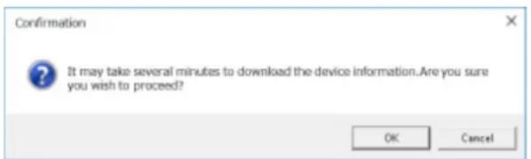
→ The downloading status window will be displayed.

To cancel downloading device information, click the [Cancel] button on the displayed status notification window.
Step 6
Confirm the displayed messages and proceed to the next step.
- Click the [OK] button.

→ The confirmation window will close.
- Go to step 8.
- Confirm the message indicated in the window.

Note:
- Check if the entered device information is correct. If the information has been edited correctly, it indicates that the connected device or the version of the connected device may not be compatible with this software.
- Refer to "Compatible devices" for further information.
- Click the [OK] button.
→ The error window will close.
- Go back to the "Device registration" window, and check the settings.
- Then, download the device information again.
Step 7
Enter for "Device title".

Step 8
Click the [Set] button.
→ The "Device registration" window will close and the settings will be saved and applied. The registered decoder will be added to the device list.
Edit a decoder 3.3.5.1.2.
Step 1
Display the "Registered device" window of the decoder.

Step 2
Select the decoder whose information is to be edited from the list of the registered devices, and then click the [Edit] button.
→ The "Device registration" window will be displayed.

Step 3
Click the [Set] button after editing the information.
→ The "Device registration" window will close and the settings will be saved and applied.
Delete a decoder 3.3.5.1.3.
Step 1
Display the "Registered device" window of the decoder.

Step 2
Select the decoder to be deleted from the list of the registered devices.
Step 3
Click the [Delete] button.
→ The deletion confirmation window will be displayed.

Step 4
Click the [OK] button.
The device information will be deleted.
3.4. Settings relating to the user management
The settings relating to the user management such as, the user authentication setting, addition of a user, edit/deletion of user information, the user level setting, etc. can be configured.
Basic setup 3.4.1.
Click the [User management] button, and then click the [Basic setup] tab to display the "Basic setup" page. Determine whether to use the auto login function for login and whether to set a validation period for password. When setting a validation period, set the password's validation period.

■ User authentication
Select ON or OFF to determine whether or not to execute the user authentication.
When you cancel login, this software will be automatically terminated. To log in again, start this software.
User authentication ON: Require the user authentication for login
User authentication OFF (Auto log-in): Not require the user authentication for login
Single Sign-On: Logs in automatically by a domain user who logged on to Windows.
Default: ON
Note:
- Single Sign-On function is not available for the local Windows user. Log on to the domain by a LDAP user, or by a user who belongs to a LDAP group after registering a LDAP user or a LDAP group.
■ Auto login user
When "User authentication OFF" is selected, select which user shall automatically log in. This setting is available only when "User authentication OFF (auto login)" is set for "User authentication".
Auto log-in user can be selected from already registered local users and the administrators. When the user registered as the auto login user is deleted, the administrator will automatically be set as the auto login user.
■ Time-limited password
Determine whether to set the password's validation period or not. When the set validation period has passed, the password change request window will be displayed each time trying to log in to this software.
ON: Set the validation period for the password.
OFF: Not set the validation period for the password.
Default: ON
■ Password's validation period
Select the validation period for the password from the following. This setting is available only when "ON" is selected for "Time-limited password".
31 days/ 92 days/ 184 days
Default: 92 days
■ Number limit of login authentication
Select ON or OFF to determine whether or not to cancel the login when failed in the login authentication for a number of times.
ON: Number of times for login authentication is limited
OFF: Number of times for login authentication is not limited
Default: ON
■ Number of Login authentication failure
Select a number limit of login authentication from the following. This setting is available only when "ON" is selected for "Number limit of login authentication".
Once/ twice/ 3 times/ 4 times/ 5 times/ 6 times/ 7 times/ 8 times/ 9 times/ 10 times
Default: 10 times
■ Password policy
Set the requirement for the password policy (complexity).
- Policy 1: If selecting “Policy 1”, it is required to set a password that includes three or more of the following four character types.
● Upper-case alphabet character ● Lower-case alphabet character - Number
- Special character (!#\$%'()*=^\~|@`[]}{+*,<>/?_)
- Policy 2: If selecting “Policy 2”, it is required to set a password that includes two or more of the following three character types. This policy applies to the newly set password.
● Upper- and lower-case alphabet character - Number - Special character (!#\$%'()*=^\~|@`[]}{+*,<>/?_)
Default: Policy 1
Note:
• The selected password policy will be applied from the next password change or when adding a user.
■ [Set] button
The configured settings will be saved.
Administrator setup 3.4.2.
Click the [User management] button, and then click the [Administrator setup] tab to display the "Basic setup" page.
Set an administrator name and password here.
Important:
- If the administrator cannot log in to this software due to forgotten authentication information such as a user name or password, the authentication information cannot be reset. Save the user authentication information in such a way that it is kept out of the hands of third parties. • Note that if multiple users share one account, the operator cannot be identified.
- Do not set a common password for multiple users. • To enhance the security, change the password periodically.

■ Administrator name
Enter an administrator name. Enter 4 - 32 alphanumeric characters for the administrator name. The administrator name already in use cannot be used.
■ Password
Enter the password. Enter 8 - 32 alphanumeric characters and special character for the password following the password policy. The entered password will be displayed as "●".
Note:
• "&:; and a space is unavailable. • The same character string as "User name" is unavailable. - Refer to " Basic setup" for further information about the password policy.
■ Retype password
Enter a new password to be registered. Check the typing error for password. The entered password will be displayed as "*".
Level
The user level will be displayed. Level change is not available for the administrator. Always be displayed as "Administrator".
■ Operable camera
The administrator can display images from all the registered cameras and "All camera display" will be displayed. Level change is not available for the administrator.
User level setup 3.4.3.
Click the [User management] button, and then click the [User level setup] tab to display the user level setup window.
Set a level of a login user here. LV0 - LV5 are available for the user level.
- LV0 users are allowed to perform all operations except "Basic setup" of "User mng.", "Administrator setup" and "License regist.". • LV1 users are allowed to perform all operations except setting change and license registration.
- LV2 - LV5 users can perform only the operations set by the administrator. All the setting operations are not allowed.
Important:
• The user level for LV0 - LV1 cannot be changed. - Set the user level appropriately only for the required functions.

Step 1
Select operable functions for each level.
→ Functions without check mark on the check boxes are inoperable. Refer to the "Functions that can be restricted" section (+ page 54) for the functions that can be restricted.
Step 2
Click the [Set] button after determining the operable functions for each user level.
→ The settings will be saved and applied.
Functions that can be restricted
| Function | Description |
| Display the current settings | The set contents can be checked on the setup window. |
| Alarm reset/error reset | It is possible to cancel the alarm status and the error status of the recorder. |
| Print/Save as a still picture | It is possible to print/save the displayed live image or recorded image. |
| File conversion | It is possible to convert an n3r file downloaded from the recorder into an mp4 file. |
| Download | It is possible to manually download recorded images. |
| Manual recording | It is possible to start/stop recording manually. |
| Recorder control | It is possible to operate the recorder including searching, playing recorded images on the recorder. |
| Preset position registration | It is possible to register the preset positions. |
| Operation of SD memory card | It is possible to operate the SD memory card in the camera. |
| Camera control | It is possible to control cameras. |
| Preset position name setup | It is possible to set the preset position name. |
| AUX terminal name setup | It is possible to set the AUX terminal name. |
| Mic setting | It is possible to operate the microphone audio collection. |
| Audio (Transmission) | It is possible to transmit audio (from the PC to the camera). |
| Display the alarm log | It is possible to display the alarm logs. |
| Display the device error log | It is possible to display the device error logs. |
| Display the network error log | It is possible to display the network error logs. |
| Face registration (*1) | Person information can be registered. |
| Display alarm/Display face search result (*1) | Alarm can be checked. Face search can be performed. |
| Delete a face alarm (*1) | Face matching alarm and unregistered face detection alarm can be deleted in the face search monitor. |
| Output a face alarm search list /Output a face search list (*1) | The alarm search result and the face search result can be output as a HTML in the face search monitor. |
| Area setting in face alarm (*1) | Area information setting can be performed in the face search monitor. |
| People Search (*2) | People Search can be performed. |
| Output People Search result (*2) | People search result can be output in HTML on the face search monitor. |
| Visibility Enhancement parameter setting (*2) | The detailed parameters for “Visibility Enhancement” can be set. |
Important:
- Only "LV0" and "LV1" can be set for "Display the current settings".
- When "Camera control" is set to non-selected state, "Preset position registration" and "Operation of SD memory card" will automatically turn to non-selected state.
- When "Recorder control" is set to non-selected state, "Manual recording" will automatically turn to non-selected state.
- When "Camera control" and "Recorder control" are set to non-selected state, "Mic setting" will automatically turn to non-selected state.
- When "Mic setting" is selected, "Camera control" and "Recorder control" will automatically turn to selected state.
- When "Output a face alarm search list" is selected, "Display alarm/Display face search result" will be selected automatically.
- When "People Search" is selected, "Display alarm/Display face search result" will be selected automatically.
- When "Output People Search result in HTML file" is selected, "Display alarm/Display face search result" and "People Search" will be selected automatically.
Default:
| Item | LV0 | LV1 | LV2 | LV3 | LV4 | LV5 |
| Display the current settings | ○ ○ | |||||
| Alarm reset/error reset | ○ ○ | |||||
| Print/Save as a still picture | ○ ○ | ○ | ||||
| File conversion | ○ ○ | ○ | ||||
| Download | ○ ○ | ○ | ||||
| Manual recording | ○ ○ | |||||
| Recorder control | ○ ○ | ○ ○ | ||||
| Preset position registration | ○ | ○ | ○ | ○ | ○ | |
| Operation of SD memory card | ○ ○ | ○ | ||||
| Camera control | ○ | ○ | ○ | ○ | ○ | |
| Preset position name setup | ○ ○ | ○ | ||||
| AUX terminal name setup | ○ ○ | ○ | ||||
| Mic setting | ○ | ○ | ○ | ○ | ○ | |
| Audio (Transmission) | ○ | ○ | ○ | ○ | ○ | |
| Display the alarm log | ○ | ○ | ○ | ○ | ○ | |
| Display the device error log | ○ | ○ | ○ | ○ | ○ | |
| Display the network error log | ○ | ○ | ○ | ○ | ○ | |
| Face registration (*1) | ○ ○ | |||||
| Display alarm/Display face search result (*1) | ○ ○ | ○ ○ | ||||
| Delete a face alarm (*1) | ○ ○ | ○ | ||||
| Output a face alarm search list /Output a face search list (*1) | ○ ○ | ○ | ||||
| Area setting in face alarm (*1) | ○ ○ | ○ | ||||
| People Search (*2) | ○ ○ | ○ ○ | ||||
| Output People Search result (*2) | ○ ○ | ○ | ||||
| Visibility Enhancement parameter setting (*3) | ○ ○ |
*1 It will become available after the license for the WV-ASE231 is added. *2 It will become available after the license for the WV-ASE231 is added and the people search server exists. *3 It will become available after the license for the WV-ASE205 is added.
User setup 3.4.4.
It is possible to add/edit/delete a user who can operate this software and set the display items.
Up to 32 users can be registered in total of local user, LDAP user, and LDAP group.
Important:
• Note that if multiple users share one account, the operator cannot be identified. - Do not set a common password for multiple users. • To enhance the security, change the password periodically.
3.4.4.1. Register a user
Add a local user 3.4.4.1.1.
Step 1
Click the [User management] button, and then click the [User setup] tab to display the "User setup" page.

The details of the window are as follows.
■ User list
Names of the registered users will be displayed in list form.
When clicking a user name, the "Setup" item of the selected user will be displayed.
■ Search field
Searches for a registered user from "User list".
■ [Add] button
Creates a new user and displays the "Setup" item.
■ [Delete] button
Deletes the user selected from "User list".
■ [LDAP search] button
Displays "User/Group selection".
Note:
- This button is disabled when "OFF" is set for "Directory Service".
■ Number of registration
Displays "Current number of registration"/"Maximum number of registration".
Step 2
Click the [Add] button.
→ The "Setup" item of a user to be added newly will be displayed.

Note:
- The [Add] button will become unavailable when reached the maximum number of the user registration (32 users).
The details of the window are as follows.
■ User name
Enter a user name. Enter 4 - 32 alphanumeric characters for the user name.
Symbols, special characters can not be used. The user name already in use cannot be entered.
■ Password
Enter the password. Enter 8 - 32 alphanumeric characters and special character for the password following the password policy. The entered password will be displayed as "●".
Note:
• "&:;" and a space are unavailable. • The same character string as "User name" is unavailable. - Refer to "Basic setup" for further information about the password policy.
■ Retype password
Enter a new password to be registered. Check the typing error for password.
The entered password will be displayed as "*".
■ Level
Select the user level to be applied to the selected user from the following.
■ Displayable camera selection
When the [Select] button is clicked, "Set a displayable camera" will be displayed.
■ Displayable group selection
When the [Select] button is clicked, "Set a displayable group" will be displayed.
■ Displayable sequence selection
When the [Select] button is clicked, "Set a displayable sequence" will be displayed.
■ Displayable map selection
When the [Select] button is clicked, "Set a displayable map" will be displayed.
■ Operation window (multi-screen) with the maximum number of areas
Select a multi-screen pattern of the operation window from the following.
1-screen/ 2-screen/ 3-screen/ 4-screen/ 5-screen/ 6-screen/ 7-screen/ 9-screen/ 10-screen/ 13-screen/ 16-screen
After the license for the Extension Software WV-ASE202 is added, select a setting value from the following.
1-screen/ 2-screen/ 3-screen/ 4-screen/ 5-screen/ 6-screen/ 7-screen/ 9-screen/ 10-screen/ 13-screen/ 16-screen/ 25-screen/ 36-screen/ 49-screen/ 64-screen
■ Live window (multi-screen) with the maximum number of areas
Select a multi-screen pattern of the live window from the following.
--/ 1-screen/ 2-screen/ 3-screen/ 4-screen/ 5-screen/ 6-screen/ 7-screen/ 9-screen/ 10-screen/ 13-screen/ 16-screen
Note:
- When not using the live window, select "--".
■ Live window1 (Available after the licenses for the WV-ASE202 are added)
Select a maximum number of areas (multi-screen pattern) of Live window 1 from the following.
--/ 1-screen/ 2-screen/ 3-screen/ 4-screen/ 5-screen/ 6-screen/ 7-screen/ 9-screen/ 10-screen/ 13-screen/ 16-screen/ 25-screen/ 36-screen/ 49-screen/ 64-screen
■ Live window2 (Available after the licenses for the WV-ASE202 are added)
Select a maximum number of areas (multi-screen pattern) of Live window 2 from the following.
--/ 1-screen/ 2-screen/ 3-screen/ 4-screen/ 5-screen/ 6-screen/ 7-screen/ 9-screen/ 10-screen/ 13-screen/ 16-screen/ 25-screen/ 36-screen/ 49-screen/ 64-screen
■ Live window3 (Available after the licenses for the WV-ASE202 are added)
Select a maximum number of areas (multi-screen pattern) of Live window 3 from the following.
--/ 1-screen/ 2-screen/ 3-screen/ 4-screen/ 5-screen/ 6-screen/ 7-screen/ 9-screen/ 10-screen/ 13-screen/ 16-screen/ 25-screen/ 36-screen/ 49-screen/ 64-screen
■ Live window4 (Available after the licenses for the WV-ASE202 are added)
Select a maximum number of areas (multi-screen pattern) of Live window 4 from the following.
--/ 1-screen/ 2-screen/ 3-screen/ 4-screen/ 5-screen/ 6-screen/ 7-screen/ 9-screen/ 10-screen/ 13-screen/ 16-screen/ 25-screen/ 36-screen/ 49-screen/ 64-screen
■ [Set] button
The configured settings will be saved.
Step 3
Click the [Set] button after editing the information.
→ The settings will be saved.
Note:
• For registration, a same name is not allowed among local user, LDAP user, and LDAP group. - If a user in a LDAP group has a same name with a local user or a LDAP user, the priority is given to the user level of the local user or LDAP user.
3.4.4.1.2. Add an LDAP user or an LDAP group
Step 1
Display the "User setup" page.
Step 2
Click the [LDAP search] button.
→ "User/Group selection" will be displayed.

Note:
- The [LDAP search] button will become unavailable when the maximum number of user registrations (32 users) is reached.
The details of the window are as follows.
■ Search for a user name
Enter a character string for searching. Wild cards can be used.
■ [Search] button
Start searching for a specific character string in the Active Directory.
Note:
- When the "Search for a user name" field is blank, the button is disabled.
If the search is not performed over Active Directory, the following screen will be displayed.

If the screen is displayed, check the following:
The Active Directory is correctly set up.
The Active Directory is running.
Network is connected.
When no result is obtained after searching, the following screen will be displayed.

■ User list
Displays the searched users in a list.
■ Group list
Displays the searched groups in a list.
Step 3
Select a user or a group to be registered and click the [Select] button.
→ The "Setup" item will be displayed.

Step 4
Click the [Set] button after editing the information.
→ The settings will be saved.
Note:
• For registration, a same name is not allowed among local user, LDAP user, and LDAP group. - Once a LDAP group is registered, login of all users included in the group by a same user level will become available. - If a user in a LDAP group has a same name with a local user or a LDAP user, the priority is given to the user level of the local user or LDAP user.
3.4.4.2. Edit the user information
Step 1
Display the "User setup" page.
Step 2
Select a user to be edited from "User list".
→ The "Setup" item will be displayed.
Refer to the descriptions of step 2 of "Add a local user" for each item.
Step 3
Click the [Set] button after editing the information.
→ The settings will be saved.
3.4.4.3. Delete the user
Step 1
Display the "User setup" page.
Step 2
Select a user to be deleted from "User list".
Step 3
Click the [Delete] button.
→ The deletion confirmation window will be displayed.
Step 4
Click the [OK] button.
→ The user information will be deleted.
Important:
- When user information of the user registered as the auto login user is deleted, the administrator will automatically be set as the auto login user.
3.4.4.4. Set a displayable camera
The administrator can determine operable cameras depending on the users.
Step 1
Display the "User setup" page.
Step 2
To add a user, click the [Add] button. To edit a user, select a user name from [User list].
→ The "Setup" item will be displayed.
Step 3
Click the [Select] button of the "Displayable camera".
→ "Displayable camera setup" will be displayed.

The details of the window are as follows.
■ [Camera] tab
The registered devices will be displayed in "Camera selection list" in the tree format.
■ [Folder] tab
Cameras will be displayed in "Camera selection list" in the folder tree format.
■ Search field
Searches for a registered device name or a folder name from "Camera selection list".
■ Camera selection list
Displays the device tree or the folder tree.
Selects a device from which images are to be displayed when a user logged in to this software.
Devices whose check box is not checked will not be displayed.
All devices are selected by default.
■ [Select All] button
Selects all the listed devices.
Step 4
Click the [Set] button after editing the information.
→ The settings will be saved.
Important:
- Live images directly from the camera can be displayed even if "--" is selected for "Camera partitioning" on the setup menu of the recorder (not allowing live images to be monitored) when the camera is selected as an operable camera with this software.
3.4.4.5. Set a displayable group
A displayable group can be set for each user.
Step 1
Display the "User setup" page.
Step 2
To add a user, click the [Add] button. To edit a user, select a user name from [User list].
The "Setup" item will be displayed.
Step 3
Click the [Select] button of the "Displayable group".
The "Displayable group setup" window will be displayed.

The details of the window are as follows.
■ Search field
Searches for a registered group name from the "Group selection list".
■ Group selection list
The registered groups will be displayed in list form.
Selects a displayable group when a user logs in to this software.
When there is no mark on the check box, no image will be displayed after login.
All groups are selected by default.
■ [All select] button
Selects all groups listed in the "Group selection list".
Step 4
Click the [Set] button after editing the information.
→ The settings will be saved.
3.4.4.6. Set a displayable sequence
Displayable sequence can be set for each user.
Step 1
Display the "User setup" page.
Step 2
To add a user, click the [Add] button. To edit a user, select a user name from [User list].
→ The "Setup" item will be displayed.
Step 3
Click the [Select] button of the "Displayable sequence".
→ "Displayable sequence setup" will be displayed.

The details of the window are as follows.
■ Search field
Searches for a registered sequence name from "Sequence selection list".
■ Sequence selection list
The registered sequences will be displayed in list form.
Select a displayable sequence when a user logged in to this software.
When there is no mark on the check box, no image will be displayed after login.
All sequences are selected at the default.
■ [All select] button
Selects all sequences listed in "Sequence selection list".
Step 4
Click the [Set] button after editing the information.
→ The settings will be saved.
3.4.4.7. Set a displayable map
Displayable map can be set for each user.
Step 1
Display the "User setup" page.
Step 2
To add a user, click the [Add] button. To edit a user, select a user name from [User list].
→ The "Setup" item will be displayed.
Step 3
Click the [Select] button of the "Displayable map".
→ "Displayable map setup" will be displayed.

The details of the window are as follows.
■ Search field
Searches for a registered map name from "Map selection list".
■ Map selection list
The registered maps will be displayed in list form.
Selects a displayable map when a user logged in to this software.
When there is no mark on the check box, no image will be displayed after login.
All maps are selected at the default.
■ [All select] button
Selects all maps listed in "Map selection list".
Step 4
Click the [Set] button after editing the information.
→ The settings will be saved.
Settings relating to folder 3.5.
The folder tree displayed when “Folder tree” is selected for “Camera tree Type” in “Tree display” (Drawing and audio setup) can be edited.
Add a folder 3.5.1.
Step 1
Click the [Folder] button to display the folder setup window.

The details of the window are as follows.
■ Search field
Searches for a registered device name from "Camera selection list".
■ Camera selection list
The registered devices will be displayed in the tree view.
■ Folder list
The registered camera names will be displayed in folder form.
■ Ascending sort button (▼)
Sort the folder list in ascending order.
For how to sort, refer to "Change the order of the folder list".
■ Descending sort button (☐)
Sort the folder list in descending order.
For how to sort, refer to "Change the order of the folder list".
■ [New folder] button
Create a new folder.
■ [Edit] button
Edits a folder name of an existing folder.
■ [Delete] button
Delete an existing folder or an added camera.
■ Preview
A preview image from the camera selected from the "Camera selection list" will be displayed.
Important:
• A preview image can be displayed only in the following cases: - When receiving live images from a camera that is not registered in a recorder. - When directly receiving live images from a camera registered in a recorder, not through the recorder. ● When acquiring live images via ND400 or NX-series: - When using a recorder other than ND400 and NX-series and selecting [Recorder] for [Live image source], the preview display is unavailable. - If the camera does not support this software ("Compatible cameras"), such as an ONVIF connection camera, the preview image will not be displayed. - In the case of a Fisheye camera, the preview image becomes fish-eye display irrespective of the setting.
■ Device title
A name of the camera selected from the camera selection list will be displayed.
■ [Set] button
The configured settings will be saved.
■ [Cancel] button
Cancels the edited contents and resets the contents to the state before editing.
Step 2
In "Folder creation", click a position where a folder is to be added.
Step 3
Click the [New folder] button.
→ A new folder will be created.

Note:
- A folder can also be added from the right-click menu displayed by a right-click in "Folder tree".
Step 4
Click the [Edit] button and enter a folder name.
Note:
• Enter up to 16 characters for the folder name. The following characters are unavailable: \ ! % ^ ' < = > @ [ ¥ ] ^ _ ' { | } ~. Up to 1000 folders can be added. It is also possible to add a folder within a folder. A folder hierarchy of up to 10 levels can be created. The created folder can be moved by dragging and dropping anywhere in the "Folder list". It is also possible to move the folder into another folder. When a folder with the same name exists in the destination folder, a serial number such as (2), (3), ... will automatically be added.
Step 5
Click the [Set] button.
→ The settings will be saved.
Edit a folder 3.5.2.
3.5.2.1. Edit the registered folder name
Step 1
Display the folder setup window.
Step 2
In "Folder list", click a folder name to be edited.

Step 3
Click the [Edit] button and edit the folder name.

Note:
- A folder name can also be edited from the right-click menu displayed by a right-click in "Folder list".
Step 4
Click the [Set] button.
→ The settings will be saved.
3.5.2.2. Add a camera into a folder
Step 1
Display the folder setup window.
Step 2
Drag and drop a camera in "Camera selection list" to be added into "Folder list".
Or double-click a camera in "Camera selection list" to be added.
→ The camera will be added.
The camera will be added to the camera on which it is dropped.

The camera will be added to the end of the list in the folder on which it is dropped.

Step 3
Click the [Set] button.
→ The settings will be saved.
Note:
- It is also possible to collectively add cameras in the recorder or in the encoder by dragging and dropping a recorder or an encoder. • It is possible to register the same camera in different folders.
- Up to 32000 cameras can be registered in "Folder creation".
3.5.2.3. Delete a camera in a folder
Step 1
Display the folder setup window.
Step 2
Select a camera to be deleted in "Folder creation".

Step 3
Click the [Delete] button.
→ The deletion confirmation window will be displayed.

Note:
- A camera can also be deleted from the right-click menu displayed by a right-click in "Folder list".
Step 4
Click the [OK] button.
→ The camera will be deleted.
Step 5
Click the [Set] button.
→ The settings will be saved.
Delete a folder 3.5.3.
Step 1
Display the folder setup window.
Step 2
Select a folder to be deleted from "Folder list".
Step 3
Click the [Delete] button.
→ The deletion confirmation window will be displayed.

Note:
- A folder can also be deleted from the right-click menu displayed by a right-click in "Folder list".
Step 4
Click the [OK] button.
→ The folder will be deleted.
Step 5
Click the [Set] button.
→ The settings will be saved.
3.5.4. Change the order of the folder list
The following are descriptions about how to change the order of the folders and the cameras in the list.
■ Drag and drop
The order of the folders and the cameras in the folder list can be changed.
Drag a folder and place the mouse cursor at the upper part of the other folder and drop.
→The folder will be moved above the folder you placed the cursor on.

Drag a folder and place the mouse cursor at the lower part of the other folder and drop.
→The folder will be moved below the folder you placed the cursor on.


Drag a folder and place the mouse cursor at the center of the other folder, then drop.


Drag a camera downward and drop it on another camera.
→The camera will be moved below the camera you placed the cursor on.


Drag a camera upward and drop it on another camera.
→The camera will be moved above the camera you placed the cursor on.


Drag a camera and drop it on a folder.
Refer to "Add a camera into a folder" for further information.

The order of the folders and the cameras in the folder list can be sorted in ascending or descending order.
Note:
- Sorting can be performed per folder or camera. • The following describes the selecting points in the folder list.
Unselected: The folder and the camera at the uppermost layer.
Folder: The folders and cameras directly under the selected folder.
Camera: The folders and the cameras in the layer same as the selected layer.
< Click the pop-up menu>
The order of the folders and the cameras in the folder list can be sorted at once in ascending or descending order.
When right-clicking on the folder list, the pop-up menu [Sort all (ascending order)] and [Sort all (descending order)] will be displayed.
| New folder |
| Edit |
| Delete |
| Sort all (ascending order) |
| Sort all (desending order) |
Note:
- Sorting can be performed per folder or camera. • The folders and cameras in the lower layer can be sorted as well.
3.6. Settings relating to group
A combination of the screen pattern and the cameras can be registered as a group.
Up to 16 cameras can be registered in a group (up to 64 cameras when the license for the extension software WV-ASE202 is added). Up to 400 groups can be registered.
Register a group 3.6.1.
Step 1
Click the [Group] button to display the group setup window.

The details of the window are as follows.
■ Search field (group list)
Searches for a registered group name from "Group list".
■ Registered group
The registered group names will be displayed in folder form.
■ Ascending sort button (↓)
Sort the group list in ascending order.
For how to sort, refer to "Change the order of the group list".
■ Descending sort button (↑)
Sort the group list in descending order.
For how to sort, refer to "Change the order of the group list".
■ [New group] button
Creates a new group.
■ [New folder] button
Create a new folder.
■ [Delete] button
Deletes the group or the folder selected from the group list.
■ Number of group
Number of the registered groups will be displayed.
Note:
- Up to 400 groups can be registered.
■ Number of folders
The number of registered folders will be displayed.
Note:
- Up to 1000 folders can be created.
Name
Enter a group name. Enter up to 16 characters for the group title.
The following characters are unavailable.
! \$ % '<=> @ [¥] ^ _ ` {|} \~ The group title already in use cannot be entered.
■ Detail
Enter details of the group. Enter up to 64 characters for details.
The following characters are unavailable.
! % ^ lt; = gt; @ [] ^ _ |
■ [Camera] tab
The registered devices will be displayed in "Camera selection list" in the tree format.
■ [Folder] tab
Cameras will be displayed in "Camera selection list" in the folder tree format.
■ Search field (camera selection list)
Searches for a registered device name or a folder name from "Camera selection list".
■ Camera selection list
Displays the device tree or the folder tree.
■ Number of camera
Select the screen pattern to determine the number of cameras.
The icons indicate the screen pattern used for the group display as follows.
| Icon Description | |
 | Display images on 1-screen. |
 | Display images on 2A-screen. |
 | Display images on 2B-screen. |
 | Display images on 3A-screen. |
 | Display images on 3B-screen. |
 | Display images on 3C-screen. |
 | Display images on 4-screen. |
 | Display images on 4E-screen. |
 | Display images on 5-screen. |
 | Display images on 6-screen. |
 | Display images on 6A-screen. |
 | Display images on 7-screen. |
 | Display images on 7A-screen. |
 | Display images on 9-screen. |
 | Display images on 10-screen. |
 | Display images on 13-screen. |
 | Display images on 16-screen. |
 | Display images on 4M-screen. 4M-screen can be set only for multi-sensor camera. Cameras other than multi-sensor cameras cannot be placed. |
The following are available after the license for the WV-ASE202 is added.
| Icon Description | |
 | Display images on 25-screen. |
 | Display images on 36-screen. |
 | Display images on 49-screen. |
 | Display images on 64-screen. |
■ Group layout
A preview image from the camera to be registered in a group will be displayed. Drag and drop one of a recorder icon, an encoder icon, a camera icon or a folder icon from "Camera selection list" to arrange a camera.
Note:
- When the group layout area is right-clicked, the "Delete" menu will be displayed.
- By selecting the "Delete" menu, the settings of the area can be deleted.
■ Preview
A preview image from the camera selected in the "Group layout" will be displayed.
Important:
• A preview image can be displayed only in the following cases: - When receiving live images from a camera that is not registered in a recorder - When directly receiving live images from a camera registered in a recorder, not through the recorder - When acquiring live images via ND400 or NX-series - When using a recorder other than ND400 and NX-series and selecting [Recorder] for [Live image source], the preview display is unavailable. - If the camera does not support this software ("Compatible cameras"), such as an ONVIF connection camera, the preview image will not be displayed. - In the case of a Fisheye camera, the preview image becomes fish-eye display irrespective of the setting.
■ Device title
The camera name selected in "Group layout" will be displayed.
■ [Set] button
The configured settings will be saved.
■ [Cancel] button
Cancels the edited contents and resets the contents to the state before editing.
Step 2
Click the [New group] button.
→ A new group will be added.

Note:
- The [New group] button will become unavailable when the maximum number of group registrations (400 groups) is reached.
Step 3
Enter a group name for "Name" and details of group for "Detail".
Step 4
Select an icon from "Number of camera selection" to determine the number of cameras to be displayed in "Group layout".
Step 5
By dragging a device icon from "Camera selection list" and dropping it to arrange it in "Group layout", and then click the [Set] button.
→ The settings will be saved and the group will be added to the group list.

Important:
• The camera already registered in the group cannot be added to the same group.
Edit group information 3.6.2.
Step 1
Display the "Group" page.
Step 2
Select a group to be edited from "Group list".
→ Information of the selected group will be displayed.
Step 3
Click the [Set] button after editing the information.
Refer to descriptions after step 2 of "Register a group" for each item.
→ The settings will be saved.
Delete a group 3.6.3.
Step 1
Display the "Group" page.
Step 2
Select a group to be deleted from "Group list".
Step 3
Click the [Delete] button.
→ The deletion confirmation window will be displayed.
Step 4
Click the [OK] button.
→ The group information will be deleted.
Note:
- When a group set as the default screen is deleted, "--" will be displayed on the "Administrator setup" page, on the "User regist." window, and for "Default screen" on the "Live window" page.
- On the operation window, a black screen will be displayed.
Manage groups with folders 3.6.4.
It is possible to manage the created groups using folders. The following are descriptions of how to manage the created groups with folders.
3.6.4.1. Register a folder
Step 1
Display the "Group" page.
Step 2
In "Group list", click a position where a folder is to be added.
Step 3
Click the [New folder] button.
→ When a new folder will be created, enter a folder name.

Note:
- A folder can also be added from the right-click menu displayed by a right-click in "Folder list".
- Enter up to 16 characters for folder name. The following characters are unavailable.
- Up to 1000 folders can be added. It is also possible to add a folder in a folder. Folder hierarchy of up to 10 levels can be created.
- The created folder can be moved by dragging and dropping anywhere in "Group list". It is also possible to move the folder into other folder. When a folder having the same name exists in the destination folder, a serial number such as (2), (3), ... will automatically be added.
Step 4
Click the [Set] button.
→ The settings will be saved.
3.6.4.2. Edit a folder
3.6.4.2.1. Edit the registered folder name
Step 1
Display the "Group" page.
Step 2
In "Group list", click a folder name to be edited.
Step 3
Edit the folder name
Step 4
Click the [Set] button.
→ The settings will be saved.
Add a group in a folder 3.6.4.2.2.
Step 1
Display the "Group" page.
Step 2
Drag a group in "Group list" and drop onto a folder.
→ The group will be added.
The group will be added to the group on which it is dropped.
The camera will be added to the end of the list in the folder on which it is dropped.
Step 3
Click the [Set] button.
→ The settings will be saved.
Delete a group in a folder 3.6.4.2.3.
Step 1
Display the "Group" page.
Step 2
Select a group to be deleted from "Group list".
Step 3
Click the [Delete] button.
→ The deletion confirmation window will be displayed.
Step 4
Click the [OK] button.
→ The group will be deleted.
3.6.4.3. Delete a folder
Step 1
Display the "Group" page.
Step 2
Select a folder to be deleted from "Group list".
Step 3
Click the [Delete] button.
The deletion confirmation window will be displayed.
Step 4
Click the [OK] button.
The folder will be deleted.
Note:
- When a group set as the default screen is deleted, "--" will be displayed on the "Administrator setup" page, on the "User regist." window and for "Default screen" on the "Live window" page.
- On the operation window, a black screen will be displayed.
Change the order of the group list 3.6.5.
The following are descriptions about how to change the order of the folders and the groups in the list.
■ Drag and drop
The order of the folders and the groups in the folder list can be changed.
Drag a folder and place the mouse cursor at the upper part of the other folder and drop.
The folder will be moved above the folder you placed the cursor on.

Drag a folder and place the mouse cursor at the lower part of the other folder and drop.
The folder will be moved below the folder you placed the cursor on.


Drag a folder and place the mouse cursor at the center of the other folder and drop.


Drag a group downward and drop on the other group.
The group will be moved below the group you placed the cursor on.


Drag a group upward and drop on the other group.
The group will be moved above the group you placed the cursor on.

Drag a group and drop on a folder.
Refer to "Add a group in a folder" for further information.
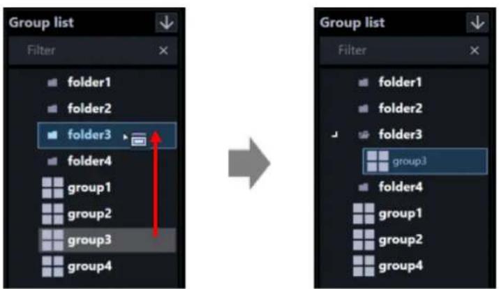
The order of the folders and the groups in the group list can be sorted in ascending or descending order.
Note:
- Sorting can be performed per folder or group. The following describes the selecting points in the group list.
Unselected: The folder and the group at the uppermost layer.
Folder: The folders and groups directly under the selected folder.
Group: The folders and the groups in the layer same as the selected layer.
< Click the pop-up menu>
The order of the folders and the groups in the group list can be sorted at once in ascending or descending order.
When the group list is right-clicked, the pop-up menu [Sort all (ascending order)] and [Sort all (descending order)] will be displayed.
| New folder |
| Sort all (ascending order) |
| Sort all (decending order) |
Note:
- Sorting can be performed per folder or group. • The folders and groups in the lower layer can be sorted as well.
3.7. Settings relating to sequence
Groups with 16 or fewer screen divisions can be registered in a sequence. Up to 64 groups can be registered in a sequence. Up to 20 sequences can be registered.
Register a sequence 3.7.1.
Step 1
Click the [Sequence] button to display the sequence setup window.

The details of the window are as follows.
■ Search field (sequence list) Searches for a registered sequence name from "Registered sequence".
■ Registered sequence
The registered sequence names will be displayed in folder form.
■ Ascending sort button (▼)
Sort the sequence list in ascending order.
For how to sort, refer to "Change the order of the sequence list".
■ Descending sort button (☐)
Sort the sequence list in descending order.
For how to sort, refer to "Change the order of the sequence list".
■ [New sequence] button
Creates a new sequence.
■ [New folder] button
Create a new folder.
■ [Delete] button
Deletes the sequence or the folder selected from the sequence list.
■ Number of sequence
Number of the registered sequences will be displayed.
Note:
- Up to 20 sequences can be registered.
■ Number of folder
Number of the registered folders will be displayed.
Note:
- Up to 1000 folders can be created.
Name
Enter a sequence name. Enter up to 16 characters for the sequence name.
The following characters are unavailable.
! \$ % '<=> @ [¥] ^ _ ` {|} \~ The sequence name already in use cannot be entered.
■ Detail
Enter details of sequence. Enter up to 64 characters for details.
The following characters are unavailable.
! % ^ lt; = gt; @ [] ^ _ I
■ Search field (group selection list)
Searches for a registered group name or folder name from "Group selection list".
■ Group selection list
The registered groups will be displayed in list form.
■ Step list
The groups registered in sequence will be displayed in list form.
Note:
- When an item of the step list is right-clicked, the "Delete" menu will be displayed.
- By selecting the "Delete" menu, the settings of the area can be deleted.
- It is possible to change the order of items of the step list by dragging and dropping them.
- Groups with 25 or more screen divisions cannot be registered in the sequence.
■ Step no.
The numbers of the groups registered in the step list will be displayed in list form.
■ Preview
A preview image of the group selected from "Group selection list" will be displayed.
Important:
• A preview image can be displayed only in the following cases: - When receiving live images from a camera that is not registered in a recorder - When directly receiving live images from a camera registered in a recorder, not through the recorder - When acquiring live images via ND400 or NX-series
- When using a recorder other than ND400 and NX-series and selecting [Recorder] for [Live image source], the preview display is unavailable.
- If the camera does not support this software ("Compatible cameras"), such as an ONVIF connection camera, the preview image will not be displayed.
- In the case of Fisheye camera, the preview image becomes fish-eye display irrespective of the setting.
Name
A name of the group selected from "Group selection list" will be displayed.
■ Detail
Details of the group selected from "Group selection list" will be displayed.
■ [Set] button
The configured settings will be saved.
■ [Cancel] button
Cancels the edited contents and resets the contents to the state before editing.
Step 2
Click the [New sequence] button.
→ A new sequence will be added.

Note:
- The [New sequence] button will become unavailable when reached the maximum number of the sequence registration (20 sequences).
Step 3
Enter a sequence name for "Name" and details of sequence for "Detail"
Step 4
By dragging a group from "Group selection list" and dropping it to arrange it in "Step list", and then click the [Set] button.
→ The settings will be saved and the sequence will be added to the sequence list.

Note:
- The group already registered in the sequence can be registered to the same sequence again as a different step.
- When reached the maximum number of the group registration (64 groups), it is impossible to add a group.
- It is possible to change the order of groups registered in "Step list" by dragging and dropping them.
- Groups with 25 or more screen divisions can not be registered in a sequence.
Edit a sequence 3.7.2.
Step 1
Display the "Sequence" page.
Step 2
Select a sequence to be edited from "Sequence list".
→ Information of the selected sequence will be displayed.
Step 3
Click the [Set] button after editing the information.
Refer to the descriptions after step 2 of "Register a sequence" for each item.
→ The settings will be saved.
3.7.3 Delete a sequence
Step 1
Display the "Sequence" page.
Step 2
Select a sequence to be deleted from the "Sequence list".
Step 3
Click the [Delete] button.
→ The deletion confirmation window will be displayed.
Step 4
Click the [OK] button.
→ Information of the selected sequence will be deleted.
Note:
- When a sequence set as the default screen is deleted, "--" will be displayed on the "Administrator setup" page, on the "User regist." window and for "Default screen" on the "Live window" page.
- On the operation window, a black screen will be displayed.
Manage sequences with folders 3.7.4.
It is possible to manage the created sequences using folders. The following are descriptions of how to manage the created sequences with folders.
3.7.4.1. Register a folder
Step 1
Display the "Sequence" page.
Step 2
In "Registered sequence", click a position where a folder is to be added.
Step 3
Click the [New folder] button.
→ When a new folder will be created, enter a folder name.

Note:
- A folder can also be added from the right-click menu displayed by a right-click in "Registered sequence".
- Enter up to 16 characters for folder name. The following characters are unavailable: ! $ % ' < = > @ [ ] ^ _ ' { | } ~
- Up to 1000 folders can be added. It is also possible to add a folder inside a folder. Folder hierarchy of up to 10 levels can be created.
- The created folder can be moved by dragging and dropping anywhere in "Registered sequence". It is also possible to move the folder into another folder. When a folder having the same name exists in the destination folder, a serial number such as (2), (3), ... will automatically be added.
Step 4
Click the [Set] button.
→ The settings will be saved.
3.7.4.2. Edit a folder
3.7.4.2.1. Edit the registered folder name
Step 1
Display the "Sequence" page.
Step 2
In "Registered sequence", click a folder name to be edited.
Step 3
Edit the folder name
Step 4
Click the [Set] button.
→ The settings will be saved.
3.7.4.2.2. Add a sequence in a folder
Step 1
Display the "Sequence" page.
Step 2
Drag a sequence in "Registered sequence" and drop onto a folder.
→ The sequence will be added.
The sequence will be added to the sequence on which it is dropped.
The camera will be added to the end of the list in the folder on which it is dropped.
Step 3
Click the [Set] button.
→ The settings will be saved.
3.7.4.2.3. Delete a sequence in a folder
Step 1
Display the "Sequence" page.
Step 2
Select a sequence to be deleted from "Registered sequence".
Step 3
Click the [Delete] button.
→ The deletion confirmation window will be displayed.
Step 4
Click the [OK] button.
→ The sequence will be deleted.
3.7.4.3. Delete a folder
Step 1
Display the "Sequence" page.
Step 2
Select a folder to be deleted from "Registered sequence".
Step 3
Click the [Delete] button.
→ The deletion confirmation window will be displayed.
Step 4
Click the [OK] button.
→ The folder will be deleted.
Note:
- When a sequence set as the default screen is deleted, "--" will be displayed on the "Administrator setup" page, on the "User regist." window and for "Default screen" on the "Live window" page. • On the operation window, a black screen will be displayed.
3.7.5. Change the order of the sequence list
The following are descriptions about how to change the order of the folders and the sequences in the list.
■ Drag and drop
The order of the folders and the sequences in the sequence list can be changed.
Drag a folder and place the mouse cursor at the upper part of the other folder and drop. →The folder will be moved above the folder you placed the cursor on.

Drag a folder and place the mouse cursor at the lower part of the other folder and drop. →The folder will be moved below the folder you placed the cursor on.

Drag a folder and place the mouse cursor at the center of the other folder and drop.


Drag a sequence downward and drop on the other sequence.
The sequence will be moved below the group you placed the cursor on.

Drag a sequence upward and drop it on another sequence.
The sequence will be moved above the group you placed the cursor on.

Drag a sequence and drop it on a folder.
Refer to "Add a sequence in a folder" for further information.

The order of the folders and the sequences in the sequence list can be sorted in ascending or descending order.
Note:
- Sorting can be performed per folder or sequence. The following describes the selecting points in the folder list.
Unselected: The folder and the sequence at the uppermost layer.
Folder: The folders and sequences directly under the selected folder.
Sequence: The folders and the sequences in the layer same as the selected layer.
< Click the pop-up menu>
The order of the folders and the sequences in the sequence list can be sorted at once in ascending or descending order.
When the sequence list is right-clicked, the pop-up menu [Sort all (ascending order)] and [Sort all (descending order)] will be displayed.
| New folder |
| Sort all (ascending order) |
| Sort all (decending order) |
Note:
- Sorting can be performed per folder or camera. • The folders and cameras in the lower layer can be sorted as well.
3.8. Settings relating to the default screen
Contains settings relating to status of the operation window and the live window at the time of launching this software.
3.8.1. Operation window
Set a display type of live images to be displayed, just after logged in, on the operation window for each user.
Step 1
Click the [Default screen] button, and then click the [Operation window] tab to display the "Operation window" page.

The details of the window are as follows.
■ User list
Names of the registered users will be displayed in list form.
When clicking a user name, the "Setup" item of the selected user will be displayed.
■ Search field
Searches for a registered user from "User list".
■ Number of registration
Displays “Current number of registration”/“Maximum number of registration”.
Note:
- Since 1 administrator and 32 users can be registered, the actual maximum number of “Number of registration” is 33.
Step 2
In "User list", click a user to be set.
→ The “Setup” item will be displayed.

The details of the window are as follows.
■ Default screen
Set a display type of live images to be displayed, just after logged in, on the operation window.
Group: The group display will start to display live images just after login.
Sequence: The sequence display will start to display live images just after login.
Default: Group
■ Default screen selection
Select a group or a sequence to be displayed just after the log-in.
It is possible to select the group registered in "Settings relating to group". When no group is registered, only "--" will be displayed. On the operation window, a black screen will be displayed.
Default: --
It is possible to select the sequence registered in "Settings relating to sequence". When no sequence is registered, only "--" will be displayed. On the operation window, a black screen will be displayed.
Default: --
Note:
• The sequence dwell time will function with the value set on the operation software.
Step 3
Click the [Set] button after editing the information.
→ The settings will be saved.
Live window 3.8.2.
Set a display type of live images to be displayed on the live window just after displaying the live window.
Step 1
Click the [Default screen] button, and then click the [Live window] tab to display the "Live window" page.

The details of the window are as follows.
■ Default screen
Set a display type of live images to be displayed on the live window just after displaying the live window.
Group: The group display will start to display live images just after login.
Sequence: The sequence display will start to display live images just after login.
Default: Group
■ Default screen selection
Select a group or a sequence to be displayed just after the log-in.
It is possible to select the group registered in "Settings relating to group". When no group is registered, only "--" will be displayed. On the operation window, a black screen will be displayed.
Default: --
It is possible to select the sequence registered in "Settings relating to sequence". When no sequence is registered, only "--" will be displayed. On the operation window, a black screen will be displayed.
Default: --
Note:
- After the license for the WV-ASE202 is added, it will become possible to set the default screen for each of the live windows from No .1 to No. 4.
■ Sequence dwell time
Select a sequence dwell time from the following. This setting can be set only when "Sequence" is selected for "Default screen".
3s/ 5s/ 10s/ 15s/ 20s/ 25s/ 30s/ 35s/ 40s/ 45s/ 50s/ 55s/ 1min
Default: 3s
■ [Set] button
The configured settings will be saved.
Step 2
Click the [Set] button after editing the information.
→ The settings will be saved.
Settings relating to map 3.9.
Register a map in advance to use the map window. Up to 100 maps can be registered. The following are descriptions of how to register/edit/delete the maps.
Register a map 3.9.1.
Step 1
Click the [Map] button to display the map setup window.

The details of the window are as follows.
■ Search field (map list)
Searches for a registered map name from "Map list".
■ Map list
Displays the registered map names in folder form.
■ Ascending sort button (↓)
Sort the map list in ascending order.
For how to sort, refer to "Change the order of the map list".
■ Descending sort button (↑)
Sort the map list in descending order.
For how to sort, refer to "Change the order of the map list".
■ [New map] button
Creates a new map.
■ [Delete] button
Deletes the map selected from the list.
■ Number of map
Number of the registered maps will be displayed.
Note:
• Up to 100 maps can be registered.
■ [Camera] tab
The registered devices will be displayed in "Camera/Map selection list" in the tree format.
■ [Folder] tab
Cameras will be displayed in "Camera/Map selection list" in the folder tree format.
■ [Map] tab
The registered maps will be displayed in "Camera/Map selection list" in the tree format.
■ Search field (camera/map selection list)
Searches for a registered camera name or map name from "Camera/Map selection list".
■ Camera/Map selection list
Displays the device tree, the folder tree or the map tree.
Name
Enter a map name. Enter up to 16 characters for the map name.
The following characters are unavailable.
! \$ % '<=> @ [¥] ^ _ ` {|} \~ The map title already in use cannot be entered.
■ Detail
Enter details of map. Enter up to 64 characters for details.
The following characters are unavailable.
■ [Map image] button
The map selection window will be displayed. Select an image file to be registered in a map.
■ Map display area
The image file will be displayed.
■ Preview
A preview image from the camera selected from "Map display area" will be displayed.
Important:
• A preview image can be displayed only in the following cases. - In case of receiving live images from a camera that is not registered in a recorder - In case of directly receiving live images from a camera registered in a recorder, not through the recorder ● In case of acquiring live images via ND400 or NX-series - When using a recorder other than ND400 and NX-series and selecting [Recorder] for [Live image source], the preview display is unavailable. - If the camera does not support this software (“Compatible cameras”), such as the ONVIF connection camera, the preview image will not be displayed. - In the case of Fisheye camera, the preview image becomes fish-eye display irrespective of the setting.
■ Set list
A camera name or a map name of an icon registered in "Map display area" will be displayed.
■ Number of registration
Number of camera icons and map icons registered in "Map display area" will be displayed.
Note:
- Up to 128 camera icons per map and up to 20 maps per map can be registered.
■ [Set] button
The configured settings will be saved.
■ [Cancel] button
Cancels the edited contents and resets the contents to the state before editing.
Step 2
Click the [New map] button.
→ A new map will be added.

Note:
- The [New map] button will become unavailable when reached the maximum number of the map registration (100 maps).
Step 3
Enter a map name for "Name" and details of map for "Detail".
Step 4
Click the [Map image] button.
→ The map selection window will be displayed.
Step 5
Select the desired image file and click the [Open] button.
→ The selected image file will be displayed in the map display area.

Step 6
Drag a camera icon or a map icon from "Camera/Map selection list" and drop it in "Map display area" to arrange it.

Note:
- When right-clicking on a camera icon, the pop-up menu will be displayed and adjustment of camera will become available. Refer to "Change the settings for the camera icon" for further information.
- When "GUI display setup" - "Display of icon name on map" is set to "ON", name of icon will be displayed under icons.
- When "GUI display setup" - "Icon frame display on the map setting window" is set to "ON", a frame border will be displayed around the camera icons.
- When right-clicking on a map image, a pop-up menu will be displayed and size of a camera icon can be adjusted from this pop-up menu.
- When 128 camera icons are already registered, it is impossible to drag and drop the camera icon onto the map display area.
- When 20 map icons are already registered, it is impossible to drag and drop the camera icon onto the map display area.
- Do not place the same camera icon in multiple maps.
Step 7
Click the [Set] button after editing the information.
→ The settings will be saved.
Edit the map 3.9.2.
Step 1
Display the "Map window" page.
Step 2
Select a map to be edited from the map list.
→ Information of the selected map will be displayed.
Step 3
Click the [Set] button after editing the information.
Refer to "Register a map" for each item.
→ The settings will be saved.
Delete the map 3.9.3.
Step 1
Display the "Map window" page.
Step 2
Select the map to be deleted, and then click the [Delete] button.
Step 3
Click the [Delete] button.
→ The deletion confirmation window will be displayed.
Step 4
Click the [OK] button.
→ The selected map will be deleted.
Important:
- When the map icon of the map to be deleted is registered in the other map, the map icon on the other map will be deleted when the [OK] button is clicked.
3.9.4. Change the order of the map list
The following are descriptions about how to change the order of the maps in the list.
■ Drag and drop
The order of the maps in the map list can be changed.
Drag a map downward and place the mouse cursor at the other map and drop.
→ The map will be moved below the map you placed the cursor on.

Drag a map upward and place the mouse cursor at the other map and drop.
The map will be moved below the map you placed the cursor on.

The order of the maps in the map list can be sorted in ascending or descending order.
3.9.5. Change the settings for the camera icon
It is possible to adjust the direction of an icon registered in a map, or to change an icon provided by this software with an icon prepared by a user, or to delete it. The size of the camera icon can be changed for each map.
When right-clicking on the registered camera icon, the pop-up menu including [Change camera icon], [Select a camera icon] and [Delete] will be displayed.

■ Change camera icon
When right-clicking on the selected camera icon and selecting one of the following directions by moving a cursor to [Change camera icon] from the pop-up menu, the camera icon can be rotated to the selected direction.
• Up: The camera icon will be rotated to indicate that the shooting direction is upward. • Down: The camera icon will be rotated to indicate that the shooting direction is downward. • Left: The camera icon will be rotated to indicate that the shooting direction is leftward. • Right: The camera icon will be rotated to indicate that the shooting direction is rightward. • Upper left: The camera icon will be rotated to indicate that the shooting direction is at the upper left. • Upper right: The camera icon will be rotated to indicate that the shooting direction is at the upper right. • Lower left: The camera icon will be rotated to indicate that the shooting direction is at the lower left. • Lower right: The camera icon will be rotated to indicate that the shooting direction is at the lower right.
Note:
- When an icon is changed with an icon prepared by a user, it is impossible to change the direction of the icon.
■ Select a camera icon
When right-clicking on the selected camera icon and selecting [Select a camera icon] from the pop-up menu, the default camera icons can be changed to desired icons prepared by a user.
Step 1
Select "Select a camera icon".
→ The "Open" window will be displayed.
Step 2
Select the icon file to be changed, and then click the [Open] button. → The camera icons on the map display area will be changed.
Note:
• The available file type for the new icons is PNG (.png). - Icon files which are smaller than 16x16 pixels or larger than 128x128 pixels cannot be loaded. - At an alarm or error occurrence, the display status of the icons on the map will differ from the default camera icons. - The changed camera icons cannot be restored to the former ones. Delete them once and arrange the camera icons again.
■ Delete
When right-clicking on the selected camera icon and selecting [Delete] from the pop-up menu, the selected camera icon can be deleted.
Note:
- By selecting [Map icon deletion] from the pop-up menu on the selected map icon, the selected map icon can be deleted.
< When right-clicked on a map image>
When right-clicking on the selected map image, the pop-up menu [Icon size] will be displayed.

■ Icon size
When moving the cursor onto the pop-up menu [Icon size] and selecting the size below, the size of the icon will change.
• 100%: The display size of the camera icon on the selected map will change to 100%.
• 90%: The display size of the camera icon on the selected map will change to 90%. • 80%: The display size of the camera icon on the selected map will change to 80%. • 70%: The display size of the camera icon on the selected map will change to 70%. • 60%: The display size of the camera icon on the selected map will change to 60%. • 50%: The display size of the camera icon on the selected map will change to 50%. • 45%: The display size of the camera icon on the selected map will change to 45%. • 40%: The display size of the camera icon on the selected map will change to 40%. • 35%: The display size of the camera icon on the selected map will change to 35%. • 30%: The display size of the camera icon on the selected map will change to 30%. • 25%: The display size of the camera icon on the selected map will change to 25%.
Default: 100%
Note:
- The icon size is common in each map. It is impossible to change the size of each icon differently on the same map. • Size change of only camera icons is available. Size change of map icons is unavailable.
3.9.6. Change the map image display magnification
The display magnification of the map image on the map setup window can be changed.
When right-clicking on the selected map image, the pop-up menu [Map setup display magnification] will be displayed.

■ Map setup display magnification
When moving the cursor onto the pop-up menu [Map setup display magnification] and selecting the size below, the display magnification of the map will be changed.
• 100%: Change the display of the map image to 100% magnification. Scaling down and displaying the full image of the map in the display area is defined as 100% magnification. • 200%: Change the display of the map image to 200% magnification. • 300%: Change the display of the map image to 300% magnification.
Default: 100%
Note:
- The display magnification will not be saved. Therefore, when the window is switched or when the window is closed and re-opened, the display magnification will return to 100%.
- The map image on the map monitor will not be changed.
3.10. Settings relating to the face search
Important:
• It is necessary to register the license for the Extension Software WV-ASE231.
Add a face search server 3.10.1.
Preliminary preparation
Before adding a face search server, prepare and configure the following.
- Register a camera to be used for the face search in ASM300. When playing recorded images from the search result, register a camera to be connected in a recorder and register the recorder to ASM300. - Register cameras to the face server to be connected. When registering, register GUID of the camera in the following format.
GUID format: "00000000-0000-0000-0000-[12 digits of IP address of the camera]" (Example) When the IP address of the camera to be registered is "192.168.0.10", GUID to be registered is "00000000-0000-0000-0000-192168000010".
- If you are using the data encryption function of the face search server, obtain the encryption key set in advance on the server. (Data encryption function is supported only for WV-ASF950.)
- Run the face search server.
Step 1
Click the [Face search] button.
→ The "Registered device" window will be displayed.

Step 2
Click the [Server registration] tab.
→ The "Registered device" window of the face search server will be displayed.
The details are as follows.
■ Registered device
Titles, model numbers, addresses, operation mode, and version of the registered face search server will be displayed in list form.
- Registered face detection: It is an operation mode in which an alarm will be issued when a person registered by the face search monitor is detected by a camera.
- Registered face/unregistered face detection: It is an operation mode that enables selecting per area whether to issue an alarm when a registered person is detected or when an unregistered person is detected by a camera.
Note:
- “-” (hyphen) will be displayed in the operation mode and the version when using WV-ASF900 or WV-ASF950 (version less than 2.00).
■ Number of registration
Number of the registered face search servers will be displayed.
■ [Add] button
Displays the "Device registration" window.
■ [Edit] button
Displays the "Device registration" window of the face search server selected from the list of "Registered devices".
■ [Delete] button
Deletes the face search server selected from the list of "Registered device".
Step 3
Click the [Add] button.
The "Device registration" window will be displayed.

Note:
• The [Add] button will become unavailable when the maximum number of device registrations is reached.
The details of the window are as follows.
■ Address
Enter the IP address of the face search server. Enter an address using up to 255 alphanumeric characters including “.” (period) and “-” (hyphen).
■ Port number
Enter a number among the following for the Port number.
1 - 65535
Default: 80
Note:
- When the WV-ASF950 secure communication setting ([Secure Settings] - [Secure Communication]) is "SSL ON", set the port number to 443.
■ [Download] button
Device information will be downloaded based on the settings of "Address" and "Port number".
■ Model
The model number of the face search server contained in the device information downloaded from the face search server will be displayed. "Unknown" will be displayed when device information is not downloaded yet.
■ Operation mode
The operation mode of the face search server obtained at the time of downloading device information is displayed. "Unknown" will be displayed when device information is not downloaded yet.
- Registered face detection: It is an operation mode in which an alarm will be issued when a person registered by the face search monitor is detected by a camera.
- Registered face/unregistered face detection: It is an operation mode that enables selecting per area whether to issue an alarm when a registered person is detected or when an unregistered person is detected by a camera.
Note:
- “-” (hyphen) will be displayed in the operation mode when using WV-ASF900 or WV-ASF950 (version less than 2.00).
■ Version
The version of the face search server obtained at the time of downloading device information is displayed. "Unknown" will be displayed when device information is not downloaded yet.
Note:
- “-” (hyphen) will be displayed in the version when using WV-ASF900 or WV-ASF950 (version less than 2.00).
■ Device title
Enter the name of the face search server. Enter up to 16 characters for the device title.
The following characters are unavailable.
! % ^ lt; = gt; @ [] ^ _ ^ |
■ Name of people search
Set the server name for people search.
Note:
- After device information is obtained, the name of the people search will be displayed only if the people search server exists.
■ [Display] button
The information window of the downloaded camera settings will be displayed. The [Setup] button will be unavailable until camera information is downloaded.
■ Encryption key (If the data encryption function is enabled on the WV-ASF950, it will be displayed after downloading the device information)
If you are using the data encryption function of the face search server, enter the encryption key. The entered key is displayed with "●". If you click the confirmation button (☐) on the right side of the entry field, you can check the entered key while clicking.
■ [Set] button
The configured settings will be saved.
Step 4
Enter the IP address and the Port number for "Address" and "Port number" respectively.
Step 5
Click the [Download] button.
Important:
- Make sure that the settings on the "NW Camera Setup" page of the setup menu of the face search server are completed before downloading the device information. When the face search server is not configured correctly, downloading of the face search server information may be impossible.
- When the settings of the setup menu of the face search server are edited, download the device information again.
Step 6
Click the [OK] button.
→ The downloading status window will be displayed.
To cancel downloading device information, click the [Cancel] button on the displayed status notification window.
Step 7
Confirm the displayed messages and proceed to the next step.
Click the [OK] button.

→ The confirmation window will close.
Go to step 8.
Confirm the message indicated in the window.
Note:
- Check if the entered device information is correct. If the information has been edited correctly, it indicates that the connected device or the version of the connected device may not be compatible with this software.
- Refer to "When downloading the device information" for further information about the displayed messages and solutions.
Click the [OK] button.
→ The error window will close.
Go back to the "Device registration" window, and check the settings.
Then, download the device information again.
Step 8
Enter for "Device title".

Step 9
Click the [Display] button.
→ The "Camera setup" window will be displayed.

The details are as follows.
■ Child server tab
Information will be switched for each child server. The IP address of the child server will be displayed on this tab.
■ CH
The camera channel numbers will be displayed.
■ Title
The camera name to be used by the face search server will be displayed. The device name set as "Video image source" will be displayed. The displayed titles cannot be edited.
■ Model
The model number of the camera to be used by the face search server will be displayed. The model number of the device set as "Video image source" will be displayed. The displayed titles cannot be edited.
■ Type
The type of the camera and the icon to be used by the face search server will be displayed. The type of the device set as "Video image source" will be displayed. The displayed icon cannot be edited.
■ Video image source
Link the cameras whose information is downloaded from the face search server to the cameras or the recorders registered in ASM300. Devices can be selected from the list of the devices that matches with the camera IP address information downloaded from the face search server. It is necessary to register devices in advance according to the setting procedures of the cameras and recorders used with ASM300. To play recorded images by operating the face search monitor, select the cameras registered in the recorder by configuring this setting.
■ Address
The address of the camera whose information is downloaded from the face search server will be displayed.
Step 10
Enter the data encryption key of the face search server in the input field of the encryption key.

Step 11
Click the [Set] button.
→ The "Device registration" window will close and the settings will be saved and applied. The registered face search server will be displayed in the list of the registered devices.

Important:
• After clicking the [Set] button, restart this software to apply the settings.
Confirm the content of the message indicated in the window.
Note:
- Refer to "When the [Set] button is clicked" for further information about the displayed messages and solutions.
Click the [OK] button.
→ The confirmation window will close.
3.10.2. Correct the face search server
Step 1
Display the "Registered device" window of the face search server.
Step 2
Select a face search server to be edited from the "Registered device", and then click the [Edit] button.
→ The "Device registration" window will be displayed.
Step 3
Click the [Set] button after editing the information.
Refer to " Add a face search server" for each item.
→ The "Device registration" window will close and the settings will be saved and applied.
Important:
• After clicking the [Set] button, restart this software to apply the settings.
3.10.3. Delete the face search server
Step 1
Display the "Registered device" window of the face search server.
Step 2
Select a face search server to be deleted from "Registered device".
Step 3
Click the [Delete] button.
→ The deletion confirmation window will be displayed.
Step 4
Click the [OK] button.
→ The device information will be deleted.
Important:
• After clicking the [Set] button, restart this software to apply the settings.
Configure the behavior setting of the face 3.10.4.
search
Step 1
Click the [Face search] button.
The "Registered device" window will be displayed.
Step 2
Click the [Behavior setting] tab.
→ The "Behavior setting" page of the face search monitor will be displayed.

The details are as follows.
■ Initial screen of the Face Search Monitor
Select the initial screen to be displayed just after starting the face search monitor.
Alarm: The "Alarm" window will be displayed as the initial screen.
Alarm search: The "Alarm search" window will be displayed as the initial screen.
Face search: The "Face search" window will be displayed as the initial screen.
People Search: The "People Search" window will be displayed as the initial screen.
Age and Gender: The "Age/Gender" window will be displayed as the initial screen.
Default: Face search
■ Automatic start of the Face Search Monitor
Select whether or not to launch the face search monitor automatically when an alarm is received from the face search server while the face search monitor is not being displayed.
ON: Automatically launch the face search window
OFF: Not launch the face search window automatically
Default: ON
■ Age and Gender tab
Select whether or not to display statistical graphs shown by age and gender brackets and by head count brackets.
ON: Display
OFF: Not display
Default: OFF
■ List of high profile persons
Select "ON" or "OFF" to determine whether to display the face image to which "Constant display" is set on the alarm notification window of the face search monitor.
ON: Display
OFF: Not display
Default: OFF
■ Face alarm deletion confirmation window
Select whether to display the confirmation window when deleting a face alarm.
ON: Display the confirmation window.
OFF: Not display the confirmation window.
Default: ON
Note:
- This function will be automatically set off when "This message won't be indicated from now on." is check-marked.
■ [Set] button
The configured settings will be saved.
Important:
• After clicking the [Set] button, restart this software to apply the settings.
Register a category name 3.10.5.
Step 1
Click the [Face search] button.
→ The "Registered device" window will be displayed.
Step 2
Click the [Category setting] tab.
→ The "Category name list" window will be displayed.

The details are as follows.
■ Category name list
The number of the registered category name, "Category name", and "Category color" will be displayed in list form.
■ Number of registration
Number of the registered category will be displayed. Up to 10 categories can be registered.
■ [Add] button
Displays the "Category name registration" window.
■ [Edit] button
Displays the category name selected from the "Category name list" on the "Category name registration" window.
■ [Delete] button
Deletes the category name selected from the "Category name list".
Step 3
Click the [Add] button.
→ The "Category name registration" window will be displayed.
Note:
- The [Add] button will become unavailable when the maximum number of category registrations is reached.
Step 4
Enter a category name.
Note:
• Up to 16 characters can be entered for a category name.
Step 5
To set a color for the category, click the [Color selection] button. → The "Color" window will be displayed.

Select the desired basic color or add a color, and then click the [OK] button.
→ The "Category name registration" page will be displayed again. The selected color will be displayed next to the [Color selection] button.

Step 6
Click the [OK] button.
→ The entered name will be saved and the "Category name registration" window will close. The category name will be added to the "Category name list".

Important:
• After clicking the [Set] button, restart this software to apply the settings.
Edit the registered category name 3.10.6. information
Step 1
Display the "Category name list" window.
Step 2
Select the category name to be edited from the "Category name list", and then click the [Edit] button.
→ The "Category name registration" window will be displayed.
Step 3
Edit the category name and click the [OK] button.
→ The edited information will be saved and the "Category name registration" window will close.
The edited category name will be displayed in the "Category name list".
Important:
• After clicking the [Set] button, restart this software to apply the settings.
3.10.7. Delete the registered category name
Step 1
Display the "Category name list" window.
Step 2
Select the category name to be deleted from the "Category name list", and then click the [Delete] button.
→ The deletion confirmation window will be displayed.
Step 3
Click the [OK] button.
→ The selected category name will be deleted.
Important:
• After clicking the [Set] button, restart this software to apply the settings.
3.11. Settings relating to the event action
Configure the settings of the event action that is to be taken upon an alarm/error occurrence. Refer to "Alarm setting" for errors during monitoring.
Refer to "Alarm action" for how to set the linkage function triggered by an alarm occurrence.
Refer to the "Error" for further information about a device error (of recorder, encoder, camera or microphone) and a network error.
Alarm setting 3.11.1.
When an alarm occurred, the event action will be taken. There are 3 event actions; displaying a message, sounding the buzzer and displaying live images from the camera in which the alarm occurred.
Note:
- Configure the settings of "Panasonic alarm protocol reception" when receiving alarm notifications from a device.
- Refer to “Panasonic alarm protocol reception” and the operating instructions of the device in use for further information.
Click the [Event] button, and then click the [Alarm] tab to display the "Alarm" page.

■ Pop-up notification
Determine whether to display the pop-up notification window at an alarm occurrence or not.
ON: Display an error message.
OFF: Not display an error message.
Default: ON
■ Buzzer
Determine whether to sound the buzzer at an alarm occurrence or not.
OFF: The buzzer will not sound when an alarm occurs.
Once: The buzzer will sound once when an alarm occurs.
Succession: The buzzer will sound continuously when an alarm occurs.
Default: Once
Note:
- The duration of the buzzer sound cannot be specified.
■ Alarm camera direct live window
Determines whether to automatically display live images from the camera where an alarm occurred in the live window.
ON: Live images will be displayed automatically.
OFF: Live images will not be displayed automatically.
Default: OFF
Note:
- When "ON" is selected for "Alarm camera direct live window", set "Live window (multi-screen) with the maximum number of areas" to a value other than "--". Refer to "Basic setup" for more information about these settings.
■ Maximum number of areas
Selects the screen pattern used to display images from the camera where an alarm occurred when "ON" is selected for "Alarm camera direct live window". This setting is available only when "ON" is selected for "Alarm camera direct live window".
1-screen/ 2A-screen/ 2B-screen/ 3A-screen/ 3B-screen/ 3C-screen/ 4-screen/ 4E-screen/ 5-screen/ 6-screen/ 6A-screen/ 7-screen/ 7A-screen/ 9-screen/ 10-screen/ 13-screen/ 16-screen
After the license for the Extension Software WV-ASE202 is added, select a setting value from the following.
1-screen/ 2A-screen/ 2B-screen/ 3A-screen/ 3B-screen/ 3C-screen/ 4-screen/ 4E-screen/ 5-screen/ 6-screen/ 6A-screen/ 7-screen/ 7A-screen/ 9-screen/ 10-screen/ 13-screen/ 16-screen/ 25-screen/ 36-screen/ 49-screen/ 64-screen
Default: 4-screen
■ Auto reset wait time
Select the wait time to reset the alarm and return to the previously displayed images before switching to live images from the camera in which an alarm occurred.
OFF/ 10s/ 20s/ 30s/ 1min/ 5min
Default: 20s
Note:
- When "OFF" is selected, the alarm will not automatically be reset. Refer to "Reset the alarm mode" for how to reset.
■ Auto change of map
Determine whether to automatically change the display to the map that has registered the camera in which an alarm occurred or not.
ON: Enable auto change of map
OFF: Disable auto change of map
Default: OFF
Note:
- When alarms occurred sequentially (within less than 1 second), the map will not be changed even if "ON" is selected for "Auto change of map".
■ [Set] button
The configured settings will be saved.
Important:
• After clicking the [Set] button, restart this software to apply the settings.
Alarm action 3.11.2.
It is possible to set the linkage function triggered when received an alarm notification.
3.11.2.1. Add an alarm action
Step 1
Click the [Event] button, and then click the [Alarm action] tab to display the "Alarm action" page.
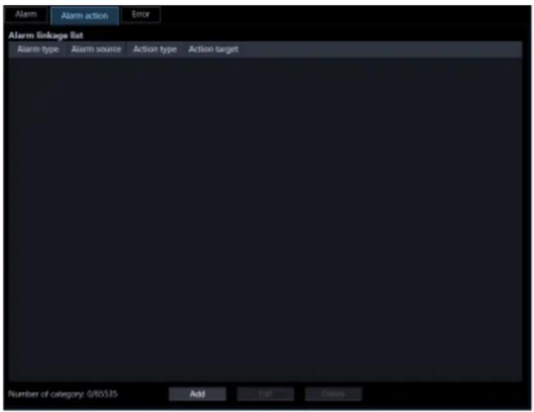
The details are as follows.
■ Alarm linkage list
The registered alarm linkage list will be displayed in list form.
■ Number of registration
Number of the registered alarm actions will be displayed.
■ [Add] button
Displays the "Alarm linkage registration" window.
■ [Edit] button
Displays the "Alarm linkage registration" window of the alarm action selected from the alarm linkage list.
■ [Delete] button
Deletes the alarm action selected from the alarm linkage list.
Step 2
Click the [Add] button.
→ The alarm linkage registration window will be displayed.

Note:
- The [Add] button will become unavailable when reached the maximum number of the alarm linkage registration (65535 alarm linkages).
The details of the window are as follows.
■ Alarm type
Select an alarm type that the alarm linkage registration is to be executed from the list.
| Item | Description |
| CAMERA SITE (Camera site alarm) | An event when an alarm (camera terminal alarm, etc.) is detected by a camera registered by recorder. |
| SCENE CHANGE DETECTION (Disturbance detection alarm) | An alarm for notifying the recorder from the camera when the orientation of the camera is changed or when the lens is covered. |
| TERMINAL ALARM | An alarm when an alarm input signal is supplied from an external device such as a door sensor to the alarm input terminal of the camera or recorder. |
| COMMAND ALARM | An alarm when receiving an alarm from a PC, etc. via a network. |
| EMERGENCY REC (Emergency recording input alarm) | An alarm notifying that emergency recording has been started manually by using an externally installed switch in the state of emergency. |
| VMD ALARM | An alarm when motion is detected in the image of the VMD area set by independent camera. |
| FACE MATCHING (Face matching alarm) | An alarm notifying that the person registered by the face search monitor was detected by the camera. |
| FACE ALARM (*1) (Unregistered face detection alarm) | An alarm notifying that the person unregistered by the face search monitor was detected by the camera in the “registered face/unregistered face detection” mode. |
*1 In the case of WV-ASF950 version 2.00 or later
Note:
- When a camera terminal alarm or VMD alarm generated by the camera is received through the recorder, it is detected as a camera site alarm (CAMERA SITE).
■ Alarm source
A name of the device selected from the alarm source list will be displayed.
■ [Camera] tab
A list of the registered devices will be displayed in "Alarm source selection list" in the tree format.
■ [Folder] tab
Cameras will be displayed in "Alarm source selection list" in the folder tree format.
■ Search field
Searches for a registered device name or a folder name from "Alarm source selection list".
■ Alarm source selection list
Displays the device tree or the folder tree.
Click to select 1 device that the alarm linkage registration is to be executed.
Note:
- If no device other than recorders can be selected from "Alarm source selection list", the [Camera] tab and the [Folder] tab are hidden.
■ Action type
Select an action at an alarm occurrence from the following.
Group display/PTZ preset/Buzzer sound
■ [Set] button
The configured settings will be saved.
Step 3
Select "Alarm type" from the list.

Step 4
Click to select 1 device that the alarm linkage registration is to be executed from "Alarm source selection list".
→ The name of the selected device will be displayed in "Alarm source".
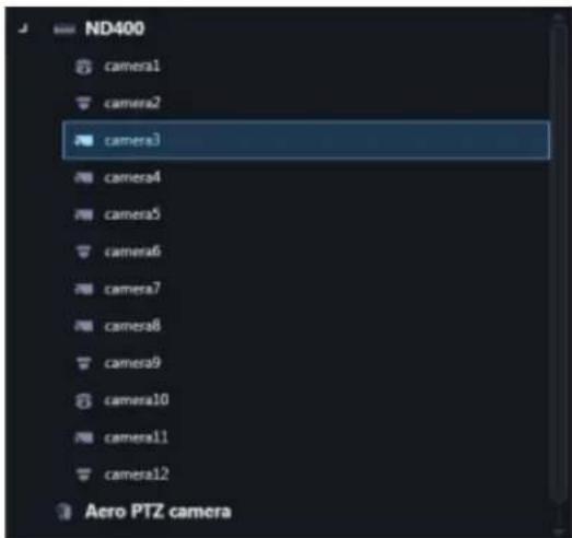
Step 5
Select "Action type" from the list.

→ The "Setup" item will be displayed.
When the Live window is active and "ON" is selected for "Alarm camera direct live window" of "Alarm setup", the live window will be switched into the alarm mode and display live images from the camera in which the alarm occurred when receiving an alarm notification. At the default, live images from the channel in which the alarm occurred, but it is possible to display images from multiple cameras that are set as a group on live window 1 by configuring the alarm action setting described below.

■ Display group
Select a display group that the alarm linkage registration is to be executed from the list. A group can be selected from the group list registered by the group setup. It is necessary to register in advance by the group setup.
■ Preview
A preview image of the group selected from "Display group" will be displayed.
Important:
• A preview image can be displayed only in the following cases. ● In case of receiving live images from a camera that is not registered in a recorder - In case of directly receiving live images from a camera registered in a recorder, not through the recorder ● In case of acquiring live images via ND400 or NX-series - When using a recorder other than ND400 and NX-series and selecting [Recorder] for [Live image source], the preview display is unavailable. - If the camera does not support this software (“Compatible cameras”), such as the ONVIF connection camera, the preview image will not be displayed. - In the case of Fisheye camera, the preview image becomes fish-eye display irrespective of the setting.
Note:
- The group setup cannot be made on this window. Only the content check of the selected group is available. • Refer to "Alarm mode display of the live window" for the alarm display to the live window.
- When the number of multi-screen areas of the group display that is set for the group linkage setting is more than the maximum number of areas for Live window 1, the alarm action display will not be performed. Make sure to select a group having areas fewer than the maximum number of areas of Live window 1 as a display group.
It is possible to display a preset position of the designated PTZ camera when received an alarm notification.
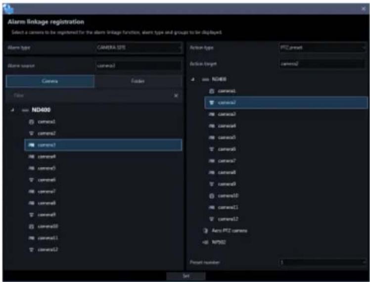
■ Action target
A name of the camera selected from "Action target selection list" will be displayed.
■ Action target selection list
Displays the device tree or the folder tree.
Click to select 1 camera whose preset position is to be displayed at an alarm occurrence.
■ Preset number
Select a preset number of the camera selected from "Action target selection list" to be displayed at an alarm occurrence from the following.
Default: 1 - 64
Note:
- The preset position name (Preset No.) can be changed to a desired one. For details, refer to "Set the preset position name".
It is possible to set the buzzer sound to be played when an alarm notification is received.

■ Action target
When the [Select] button is clicked, the file selection window will be displayed. Select an audio file to be played at an alarm occurrence.
■ Audio confirmation
When the [Play] button is clicked, the audio file selected in "Action target" will be played.
Note:
- When the alarm type [FACE ALARM] is selected in Step 3, an area is displayed in the "Alarm source selection list". At that time, "-" (hyphen), which means all areas, is displayed at the top of the selection list. Refer to "Set area" about the area.
Step 6
Enter information for the setup items and click the [Set] button.
→ The settings will be saved and the alarm linkage registration window will close.
Important:
• After clicking the [Set] button, restart this software to apply the settings.
3.11.2.2. Edit an alarm action
Step 1
Displays the alarm linkage registration window.

Step 2
Select an alarm action to be edited from the alarm linkage list, and then click the [Edit] button.
→ The alarm linkage registration window will be displayed.
Step 3
Click the [Set] button after editing the information.
Refer to " Add an alarm action" for each item.
→ The settings will be saved and the alarm linkage registration window will close.
Important:
• After clicking the [Set] button, restart this software to apply the settings.
3.11.2.3. Delete an alarm action
Step 1
Displays the alarm linkage registration window.

Step 2
Select an alarm action to be deleted from the alarm linkage list.
Step 3
Click the [Delete] button.
→ The deletion confirmation window will be displayed.

Step 4
Click the [OK] button.
→ The alarm action information will be deleted.
Important:
• After clicking the [Set] button, restart this software to apply the settings.
Error 3.11.3.
Configure the settings of the event action that is to be taken upon a recorder error/network error occurrence.
There are 2 event actions; displaying a message and sounding the buzzer.
Note:
- It is necessary to configure the "Panasonic alarm protocol reception" setting to receive device error notifications.
- Refer to “Panasonic alarm protocol reception” and the operating instructions of the device in use for further information.
Click the [Event] button, and then click the [Error] tab to display the "Error" page.

■ Pop-up notification
Determine whether to display an error message at an error occurrence or not.
ON: Display an error message.
OFF: Not display an error message.
Default: ON
■ Buzzer
Determine whether to sound the buzzer at an error occurrence or not.
OFF: The buzzer will not sound at an alarm occurrence.
Once: The buzzer will sound once at an alarm occurrence.
Succession: The buzzer will sound continuously at an alarm occurrence.
Default: Once
Note:
- Buzzer sounding duration cannot be specified.
■ [Set] button
The configured settings will be saved.
Important:
• After clicking the [Set] button, restart this software to apply the settings.
3.12. Settings relating to the communication
Configure the settings relating to the communication required to use this software.
Basic setup 3.12.1.
Click the [Communication] button, and then click the [Basic setup] tab to display the "Basic setup" page. Configure the settings of "Proxy address", "Proxy port number" and "FTP mode".

■ Proxy address
Enter the IP address of the proxy server. Enter an address using up to 255 alphanumeric characters including “.” (period) and “-” (hyphen)
■ Proxy port number
Enter the port number of the proxy server. Enter a number from 1 to 65535.
■ FTP mode
Select "Active" or "Passive" for the FTP mode.
Default: Active
■ [Set] button
The configured settings will be saved.
Important:
• After clicking the [Set] button, restart this software to apply the settings.
Note:
- Communication will not be established even when "ON" is selected for "Proxy server" on the device registration window if no value is entered for "Proxy address" and "Proxy port number" on this window.
- When using the proxy server, use an HTTP proxy server. Download function via an HTTP proxy server is available through this software normally uses the FTP function of the recorder.
3.12.2. Panasonic alarm protocol reception
Click the [Communication] button, and then click the [Panasonic alarm protocol reception] tab to display the Panasonic alarm protocol reception page.
Configure the settings of "Alarm notification (Panasonic alarm protocol notification)" and "Port number".

■ Alarm notification (Panasonic alarm protocol notification)
Determine whether to receive an alarm/error notification from the device or not.
ON: An alarm/event notification from the device will be received.
OFF: An alarm/event notification from the device will not be received.
Default: ON
■ Port number
Enter the port number used to receive Panasonic alarm protocol. Enter a number from 1 to 65535.
Default: 1818
Important:
- It is necessary to make the port number selected in "Port number" available when "Windows Firewall" of Windows 7 is on. Configure the exceptional settings of Windows Firewall by following the procedure of "Exceptional settings of Windows Firewall".
■ [Set] button
The configured settings will be saved.
3.13. Settings relating to the controller
When a camera, a group, and a sequence are selected from the system controller, assignment of a number to the camera, group, and sequence to be used is required before their selections.
Set a camera number 3.13.1.
Assign camera numbers to the registered camera names*.
* When "On" is selected for "Quad streams/Cropping mode" of the camera setup, "CH title" will be displayed instead of "Camera title".
3.13.1.1. Manually set a camera number
Step 1
Click the [Controller] button.
→ The "Camera number" page will be displayed.

The details of the window are as follows.
■ [Auto numbering] button
Assigns camera numbers automatically in order of the displayed list.
■ [Clear all] button
Clears all the camera numbers displayed on the list.
■ [File export] button
Saves the displayed list as a file in CSV format.
■ [Set] button
The configured settings will be saved.
Step 2
Click the desired camera title, and then click the camera number column respective to the clicked camera title.
→ The clicked column will become editable.

Step 3
Enter the desired camera number. Enter a number from 1 to 99999.
Step 4
Click the [Set] button.
Step 5
Restart this software to apply the settings.
3.13.1.2. Automatically set a camera number
Step 1
Display the "Camera number" page.
Step 2
Click the [Auto numbering] button.
→ The "Camera number automatic assignment" window will be displayed.

Step 3
Click the [OK] button.
→ Camera numbers will automatically be assigned in order of the displayed list.

Step 4
Click the [Set] button.
Step 5
Restart this software to apply the settings.
3.13.1.3. Export the camera number list as a file
Step 1
Display the "Camera number" page.
Step 2
Click the [File export] button.
→ The "Save As" window will be displayed.
Step 3
Click the [Save] button after designating the destination folder.
→ The camera number list will be saved in CSV format.
3.13.2. Set a group number
Assign group numbers to the registered group names.
3.13.2.1. Manually set a group number
Step 1
Click the [Controller] button.
→ The "Camera number" page will be displayed.
Step 2
Click the [Group number] tab.
→ The "Group number" page will be displayed.
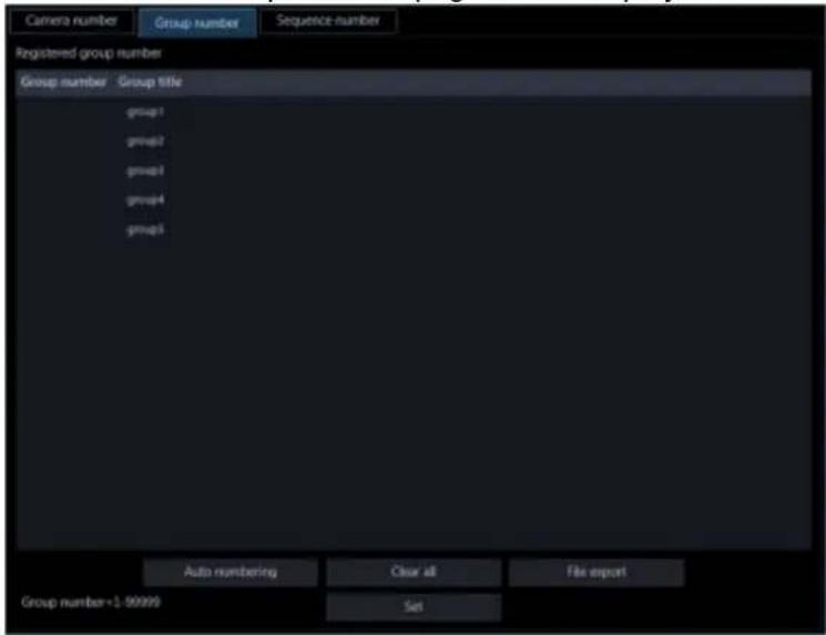
The details of the window are as follows.
■ [Auto numbering] button
Assigns group numbers automatically in order of the displayed list.
■ [Clear all] button
Clears all the group numbers displayed on the list.
■ [File export] button
Saves the displayed list as a file in CSV format.
■ [Set] button
The configured settings will be saved.
Step 3
Click the desired group title, and then click the group number column respective to the clicked group title.
→ The clicked column will become editable.
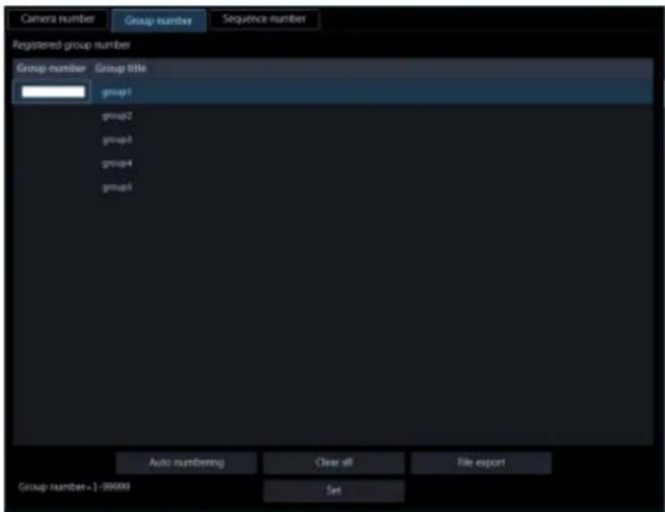
Step 4
Enter the desired group number.
Enter a number from 1 to 99999.
Step 5
Click the [Set] button.
Step 6
Restart this software to apply the settings.
3.13.2.2. Automatically set a group number
Step 1
Display the "Group number" page.
Step 2
Click the [Auto numbering] button.
→ The group number automatic assignment window will be displayed.
Step 3
Click the [OK] button.
→ Group numbers will automatically be assigned in order of the displayed list.
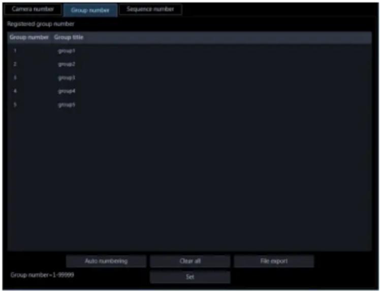
Step 4
Click the [Set] button.
Step 5
Restart this software to apply the settings.
3.13.2.3. Export the group number list as a file
Step 1
Display the "Group number" page.
Step 2
Click the [File export] button.
→ The "Save As" window will be displayed.
Step 3
Click the [Save] button after designating the destination folder.
→ The group number list will be saved in CSV format.
Set a sequence number 3.13.3.
Assign sequence numbers to the registered sequence names.
3.13.3.1. Manually set a sequence number
Step 1
Click the [Controller] button.
→ The "Camera number" page will be displayed.
Step 2
Click the [Sequence number] tab.
→ The sequence number setup window will be displayed.

The details of the window are as follows.
■ [Auto numbering] button
Assigns serial sequence numbers automatically in order of the displayed list starting from 1.
■ [Clear all] button
Clears all the sequence numbers displayed on the list.
■ [File export] button
Saves the displayed list as a file in CSV format.
■ [Set] button
The configured settings will be saved.
Step 3
Click the desired sequence title, and then click the sequence number column respective to the clicked sequence title.
→ The clicked column will become editable.

Step 4
Enter the desired sequence number. Enter a number from 1 to 99999.
Step 5
Click the [Set] button.
Step 6
Restart this software to apply the settings.
3.13.3.2. Automatically set a sequence number
Step 1
Display the "Sequence number" page.
Step 2
Click the [Auto numbering] button.
→ The sequence number automatic assignment window will be displayed.
Step 3
Click the [OK] button.
→ Sequence numbers will automatically be assigned in order of the displayed list.

Step 4
Click the [Set] button.
Step 5
Restart this software to apply the settings.
3.13.3.3. Export the Sequence number list as a file
Step 1
Display the "Sequence number" page.
Step 2
Click the [File export] button.
→ The "Save As" window will be displayed.
Step 3
Click the [Save] button after designating the destination folder.
→ The sequence number list will be saved in CSV format.
3.14. Settings relating to maintenance
The following are descriptions of how to display/save the application logs and of how to save/load/initialize the settings on the setup window.
3.14.1. Display version information
Click the [Maintenance] button, and then click the [Version information] tab to display the "Version information" window.

■ Software version
The version of this software will be displayed.
3.14.2. Display/save an application log
It is possible to search the logs filed in this software and display/save them. The displayed contents will vary depending on the selected log type. Refer to the "Descriptions of the application log list" for descriptions about the log list window that displays logs and major content of logs to be filed. The displayable log type and contents to be filed are as follows.
Alarm log: Alarm information history transmitted using Panasonic alarm protocol from devices
Device error log: Device error information history transmitted using Panasonic alarm protocol from devices
Network error log: Network error history between this software and devices
System log: System information history of this software
Operation log: Operation history of this software
Note:
- The application logs will be kept on being filed until reaching their maximum number of logs that can be stored. After reaching the maximum number, the older logs will be overwritten in order. Refer to "Descriptions of the application log list" for the maximum number of registration of logs that can be filed in this software.
3.14.2.1. Display an application log
To display logs of each type, select the log type from the drop-down list.
Step 1
Click the [Maintenance] button.
Step 2
Click the [Application log] tab.
→ The application log window will be displayed.

The details of the window are as follows.
■ Select log type
Select the log type from the following.
Alarm log/Device error log/Network error log/System log/Operation log
Default: Alarm log
■ Period designation
Determine whether to designate a period when logs have been filed.
ON: Designate a period.
OFF: Not designate a period.
Default: OFF
■ Start Time
Select the start time of a period.
■ End Time
Select the end time of a period.
■ [Display] button
Searches for logs in the designated period and displays the search result in the log list.
■ [All] button
Saves all logs of the selected log type as a file in the CSV format.
■ [Designated period] button
Saves logs of the selected log type that were filed only in the designated period as a file in the CSV format.
■ [Listed] button
Saves the logs displayed in the log list as a file in the CSV format.
■ Log
Content of the log will be displayed. Up to 1000 logs can be displayed.
Note:
• Descriptions of the listed logs differ depending on the log type. - Refer to "Descriptions of the application log list" for further information.
■ Total
Number of logs matched with the search conditions will be displayed.
■ Number of the listed logs
Number of the logs currently displayed in the log list display area.
Step 3
Select the reference period of application log and click the [Display] button.
→ Logs filed in the designated period will be displayed in the log list display area.

3.14.2.2. Save an application log
The logs displayed in the log list display area can be saved in a designated folder as a file in the CSV format.
The saving method is as follows.
Save all: All logs will be saved.
Save logs in the designate period: Logs in the designated period will be saved.
Save the listed logs: Only the logs displayed in the log list will be saved.
Step 1
Display the "Application log" page.

Step 2
Select the reference period of application log and click the [Display] button. Refer to "B" Display an application log" for each item.
→ Logs filed in the designated period will be displayed in the log list display area.

Step 3
Click the desired button ([All] button/[Designated period] button/[Listed] button) according to the desired saving method of logs.
The "Save As" window will be displayed.

Note:
- If the number of logs to be saved is large, it may take up to 1 minute to display the save screen with a name. In that case, please wait as it is without operating the screen.
Step 4
Click the [Save] button after designating the destination folder.
The application log information saving progress window will be displayed.
When the saving of the file is completed, the application log saving progress window will automatically close and the application log window will be displayed.
Note:
- When the number of logs to be saved as a file is more than 10000, the file to be saved will automatically be divided into several files.
3.14.2.3. Descriptions of the application log list Alarm log 3.14.2.3.1.
The alarm log will be filed each time an alarm occurred.
Up to 30000 system logs can be stored and up to 1000 system logs can be displayed.

■ Time & date
Time & date when the alarm occurred will be displayed.
Content
Descriptions of the alarm will be displayed.
Sender
The title of the device in which the alarm occurred will be displayed.
Note:
- When an alarm occurred in a camera that is not registered in the recorder, "--" will be displayed.
■ Camera
The title of the camera in which the alarm occurred will be displayed.
Note:
- When an alarm occurred in a device for which "On" is selected for "Quad streams/Cropping mode" of the camera setup, "CH title" will be displayed instead of "Camera title".
Device error log 3.14.2.3.2.
The device error log will be filed each time an error occurred in the device.
Up to 1000 system logs can be stored and up to 1000 system logs can be displayed.
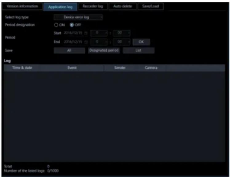
■ Time & date
Time & date when the device error occurred will be displayed.
■ Content
Descriptions of the error occurred in the device will be displayed.
■ Sender
The title of the device in which the error occurred will be displayed.
Note:
- When a device error occurred in a camera is not registered in the recorder, "--" will be displayed.
■ Camera
The title of the camera in which the error occurred will be displayed.
Note:
- When a device error occurred in a device for which "On" is selected for "Quad streams/Cropping mode" of the camera setup, "CH title" will be displayed instead of "Camera title".
3.14.2.3.3. Network error log
The network error log will be filed each time a network error occurred.
Up to 1000 system logs can be stored and up to 1000 system logs can be displayed.

■ Time & date
Time and date of the network error occurrence will be displayed.
■ Content
Descriptions of the network error will be displayed.
Sender
The title of the device in which the network error occurred will be displayed.
Note:
- When a network error occurred in a camera that is not registered in the recorder, "--" will be displayed.
■ Camera
The title of the camera in which the network error occurred will be displayed.
Note:
- When a network error occurred in a device for which "On" is selected for "Quad streams/Cropping mode" of the camera setup, "CH title" will be displayed instead of "Camera title".
The following are the network error logs to be filed.
| Log | Description |
| Recorder communication recovered. | Filed when the connection to the recorder was recovered. |
| Recorder communication error. | Filed when failed to connect to the recorder. |
| Undefined reply. (from the recorder) | Filed when received an undefined reply from the recorder. |
| Recorder user authentication error | Filed when failed to authenticate the user to connect to the recorder. |
| Maximum concurrent access. | Filed when failed to connect to the recorder due to the concurrent access limit. |
| Host authentication error. | Filed when failed to authenticate the host to connect to the recorder. |
| Encoder communication recovered. | Filed when the communication with the encoder recovered. |
| Encoder communication error | Filed when failed to connect to the encoder. |
| Camera communication recovered. | Filed when the connection to the camera was recovered. |
| Camera communication error. | Filed when failed to connect to the camera. |
| Undefined reply. (from the camera) | Filed when received an undefined reply from the camera or the encoder. |
| Camera user authentication error. | Filed when failed to authenticate the user to connect to the camera or the encoder. |
| Camera authentication method error | For details of changing the position name, refer to “Set the preset position name”. |
| Microphone connection error | Filed when failed to connect to the microphone. |
| Microphone connection recovery | Filed when the connection to the microphone was recovered. |
| Port number duplication. Filed when port numbers are redundant. When a port number is manually assigned to each camera in the unicast mode, use caution not to assign the same number to different cameras. Refer to the operating instructions of the camera in use for settings relating to the port number. | |
System log 3.14.2.3.4.
The system log will be filed each time the status of the system changed.
Up to 1000 system logs can be stored and up to 1000 system logs can be displayed.

■ Time & date
Operation time and date will be displayed.
■ Content
Descriptions of the status will be displayed.
■ User
The name of the user who operated this software will be displayed.
■ Sender
The title of the device which has been operated by the user will be displayed.
Note:
- When the device in operation is a camera that is not registered in the recorder, "--" will be displayed.
■ Camera
The title of the camera which has been operated by the user will be displayed.
Note:
- When "On" is selected for "Quad streams/Cropping mode" of the camera setup of the camera in operation, "CH title" will be displayed instead of "Camera title".
The following are the system logs to be filed.
| Log | Description |
| ASM300 started | Filed when this software is started. |
| ASM300 ended | Filed when this software is ended. |
| ASM300 user login | Filed when a user logged in this software. |
| ASM300 logout | Filed when a user logged out of this software. |
| Received a Panasonic alarm protocol from an unsupported device. | Filed when received Panasonic alarm protocol from an unsupported device. |
| Received a Panasonic alarm protocol from an unregistered device. | Filed when received Panasonic alarm protocol from an unregistered device. |
| An error occurred on Panasonic alarm protocol reception. | Filed when an error occurred in the reception of Panasonic alarm protocol. |
| An error occurred on Panasonic alarm protocol processing. | Filed when failed to implement the Panasonic alarm protocol received from the device. |
| FACE alarm reception error (operation mode inconsistency) | Filed when the operation mode (registered face detection mode) of the server registered in this software does not match when receiving "FACE ALARM". |
| Failed to delete the operation log file. | Filed when failed to delete the operation logs automatically. |
| Restart this software due to an unexpected error occurrence | Filed when an unexpected error occurred and this software is restarted. |
| Live window started. | Filed when the live window is started. |
| Live window ended. | Filed when the live window is ended. |
| ASM300 user login error | Filed when failed to read out the user information and the user failed to log in to this software. |
| A Panasonic alarm protocol reception start error. | Filed when an error occurred at the start of the reception of Panasonic alarm protocol. |
| Received an illegal Panasonic alarm protocol (Unsupported category) | Filed when the category of Panasonic alarm protocol is illegal. |
| Received an illegal Panasonic alarm protocol. (Unknown message ID) | Filed when the message ID of Panasonic alarm protocol is illegal. |
| Setup window started | Filed when the setup window is started. |
| Setup window ended | Filed when the setup window is started. |
| The setup window restarted due to an unexpected error occurrence | Filed when an unexpected error occurred and the setup window is restarted. |
| Setup window user login failed | Filed when failed to read out the user information and the user failed to log in to the setup window. |
| An unexpected error has occurred. The live software has been restarted to continue monitoring. | Filed when an unexpected error occurred and the live software was restarted. |
| Download failed (FTP connection error) | Filed when download of the file failed due to the error in the FTP access to the recorder. In this case, the following are possible causes.The FTP access is blocked by the firewall.The FTP port cannot be opened because the user name and password set at the time of device registration do not match with the administrator name and password of the recorder.It is impossible to open the FTP port since it exceeds the maximum number of connections of the recorder. |
| Download failed (FTP login error) | Filed when the FTP login to the recorder failed.In this case, the following are possible causes.The FTP login is unavailable because the user name and password set at the time of device registration do not match with the administrator name and password of the recorder. |
| Download failed (excessive FTP connections) | Filed when download of the file failed due to the concurrent FTP access limit of the recorder. |
| Download failed (other FTP errors) | Filed when an error occurred during the FTP access to the recorder. |
| Download failed (recorder unsupported version) | Filed when downloading failed since the recorder does not support the n3r-format file downloading (extension method). |
Operation log 3.14.2.3.5.
The application log will be filed each time a user operates this software.
Up to 100000 system logs can be stored and up to 1000 system logs can be displayed.

■ Time & date
Time and date when a user operated this software will be displayed.
■ User
The name of the user who operated this software will be displayed.
■ Window
The window type of this software that the user operated will be displayed.
Content
Descriptions of the operation will be displayed.
■ Sender
The title of the device which has been operated by the user will be displayed.
Note:
- When the device in operation is a camera that is not registered in the recorder, "--" will be displayed.
■ Camera
The title of the camera which has been operated by the user will be displayed.
Note:
- When "On" is selected for "Quad streams/Cropping mode" of the camera setup of the camera in operation, "CH title" will be displayed instead of "Camera title".
Recorder log 3.14.3.
It is possible to download the recorder logs filed in each recorder and display/save them.
The displayable log type and contents to be filed are as follows.
Error log: Error history of the recorder
Access log: Access history to the recorder
Event log: Event occurrence history of the recorder
Network log: Network error history of the recorder
3.14.3.1. Download a recorder log
Step 1
Click the [Maintenance] button.
→ The version information window will be displayed.

Step 2
Click the [Recorder log] tab.
The recorder log window will be displayed.

The details of the window are as follows.
- Recorder
Select the recorder from which the recorder log is to be downloaded.
■ [Download] button
Downloads the recorder log filed in the selected recorder.
Log
Descriptions of the log will be displayed.
"No.", "Time & date" and "Contents" will be displayed for every log.
Note:
- "Protocol" will also be displayed for "Network log".
■ Each log tab
Tabs of each log type will be displayed. Tab of "Error log", "Access log", "Event log" or "Network log" can be selected.
■ [Save] button
Saves the recorder log by type.
Step 3
Select the recorder and click the [Download] button.
→ The cursor will turn into an hourglass. When the download is completed, the log list will be displayed.

3.14.3.2. Save a recorder log
The designated recorder log will be saved.
Step 1
Display the "Recorder log" page.
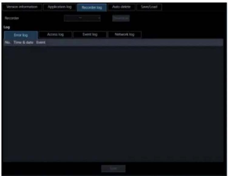
Step 2
Select the recorder and click the [Download] button.
→ The cursor will turn into an hourglass.

When the download is completed, the log list will be displayed.
Step 3
Click a tab whose log is to be saved, and the click the [Save...] button.
→ The "Save As" window will be displayed.

Step 4
Click the [Save] button after designating the destination folder.
→ The recorder log information saving progress window will be displayed.
When the saving is completed, the recorder log information saving progress window will automatically close and the recorder log window will be displayed.
3.14.3.3. Descriptions of the recorder log list
The recorder log will be filed each time an error including a network error occurred in the login recorder or in the camera connected the login recorder. Time and date when the error occurred and its descriptions will be displayed for each log.
The maximum number of logs that can be stored differs depending on the log type as follows.
Error log: Up to 100 logs (1000 logs when the recorder in use is the NV200, NV300 or NX-series)
Access log: Up to 100 logs
Event log: Up to 750 logs
Network log: Up to 1000 logs (100 logs when the recorder in use is the NV200, NV300 or the NX-series)

No.
The log number will be displayed. The younger number is given to the newer log.
■ Time & date
Time and date when the log has been filed will be displayed.
■ Protocol
The protocol type will be displayed.
■ Content
Descriptions of the occurrence (operation) will be displayed.
3.14.4. Automatically delete operation logs
Determine whether to automatically delete the filed operation logs or not. When deleting the operation logs, set the retention period of the logs. The operation logs will automatically be deleted when the set retention period has passed.
Important:
- When the PC is not started, the operation log will not be deleted even when the set retention period has been passed.
Note:
- Refer to "Descriptions of the application log list" for the maximum number of registration of logs that can be filed in this software.
Click the [Maintenance] button, and then click the [Auto delete] tab to display the "Auto delete" page.

■ Operation log auto deletion
Determine whether to automatically delete the operation log or not.
ON: The operation log will be automatically deleted.
OFF: The operation log will not be automatically deleted.
Default: ON
■ File retention period
Select the file retention period from the following. This setting can be configured only when "ON" is selected for "Operation log auto deletion".
31 days/ 92 days/ 184 days/ 366 days
Default: 92 days
■ [Set] button
The configured settings will be saved.
Important:
• After clicking the [Set] button, restart this software to apply the settings.
Save/load/initialize the setup data and 3.14.5. initialize logs
The setup data can be saved/loaded/initialized and the application logs can also be initialized.
Note:
• The following settings are not subject to setting save / load / initialization.
● [System] - [Drawing and audio setup] - [PC diagnosis (4K camera)] / [Decoding method (H.265)] ● [Maintenance] - [Recorder log] • [Registration of license]
3.14.5.1. Save the setup data as a backup
Important:
- Back up the setup data periodically by copying it onto an external hard disk drive or other storage medium. When the hard disk drive on the PC in use is damaged, it may be impossible to recover the setup data. • If the setup data is saved, all the application logs will also be saved.
Step 1
Click the [Maintenance] button.
→ The version information window will be displayed.

Step 2
Click the [Save/Load] tab.
→ The "Save/Load" page will be displayed.
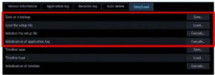
The details of the window are as follows.
■ [Save] button
Displays the "Save As" window.
■ [Load] button
Displays the [Open] window.
■ [Execute] button (Initialization of the setup file)
Displays the setup data initialization start confirmation window.
■ [Execute] button (Initialization of application log)
The initialization start confirmation window for the application logs will be displayed.
Step 3
Click the [Save] button of "Save the setup file".
→ The "Save As" window will be displayed.

Step 4
Click the [Save] button after designating the destination folder.
→ Saving of the setup data will start.
Step 5
Click the [OK] button on the confirmation window.
→ The "Save/Load" page will be displayed again.
3.14.5.2. Load the setup file
Important:
- When loading of the setup file starts, all the setup data of this software will be overwritten.
- When loading of the setup file is completed, this software will restart. • If the setup data is loaded, all the saved application logs will also be overwritten.
- The setup data is unable to be loaded if it is stored in the network drive. Save the setup data on the hard disk of the PC in advance. * If the saved application logs are older, the data will be overwritten with the older one.
Step 1
Display the "Save/Load" page.
Step 2
Click the [Load] button of "Load the setup file".
→ The "Open" window will be displayed.
Step 3
Select the setup file to be loaded, and then click the [Open] button.
→ The loading start confirmation window will be displayed.
Step 4
Click the [OK] button on the confirmation window.
→ Loading of the setup file will start.
Step 5
Click the [OK] button on the confirmation window.
→ This software will be automatically restarted.
3.14.5.3. Initialize the setup data
Important:
- When initialization of the setup file starts, all the setup data of this software will be initialized. It is recommended to back up the setup file before initializing the setup file.
- When initialization of the setup file is completed, this software will restart.
Step 1
Display the "Save/Load" page.
Step 2
Click the [Execute] button of "Initialize the setup file".
→ The initialization start confirmation window will be displayed.
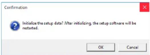
Step 3
Click the [OK] button.
→ Initialization of the setup file will start.
Step 4
Click the [OK] button on the confirmation window.
→ This software will be automatically restarted.
3.14.5.4. Initialize the application logs
Step 1
Display the "Save/Load" page.
Step 2
Click the [Execute] button of "Initialize application log".
→ The initialization start confirmation window will be displayed.

Step 3
Click the [OK] button.
→ Initialization will start.
Step 4
Click the [OK] button on the confirmation window.
Save/load/initialize the timeline data 3.14.6.
Save, load, initialize the timeline data obtained by this software.
3.14.6.1. Save the timeline
Important:
- Back up the timeline data along with setup data periodically by copying it onto an external hard disk drive or other storage medium. • This function is available only when "Master" is selected for "Timeline database".
Step 1
Display the "Save/Load" page.
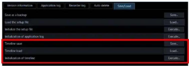
The details are as follows.
■ [Save] button
Displays the "Save As" window.
■ [Load] button
Displays the "Open a file" window.
■ [Execute] button
Displays the confirmation window for starting initialization of timeline data.
Step 2
Click the [Save] button of "Timeline save".
→ The "Save As" window will be displayed.
Step 3
Click the [Save] button after designating the destination folder.
→ Saving of the setup data will start.
Step 4
Click the [OK] button on the confirmation window.
→ The "Save/Load" page will be displayed again.
3.14.6.2. Load the timeline
Important:
- When loading of the timeline data is started, all the timeline data will be overwritten. * If the saved application logs are older, the setup data will also be overwritten with the older one.
Step 1
Display the "Save/Load" page.
Step 2
Click the [Load] button of "Timeline load".
→ The "Open" window will be displayed.
Step 3
Select the setup file to be loaded, and then click the [Open] button.
→ The loading start confirmation window will be displayed.
Step 4
Click the [OK] button on the confirmation window.
→ Loading of the setup file will start.
Step 5
Click the [OK] button on the confirmation window.
→ This software will be automatically restarted.
3.14.6.3. Initialize the timeline (Clear)
Recording information collected in the PC by the timeline database will be initialized (cleared).
Step 1
Display the "Save/Load" page.
Step 2
Click the [Execute] button of "Initialize the timeline".
→ The initialization start confirmation window will be displayed.

Step 3
Click the [OK] button.
→ Initialization will start.
Step 4
Click the [OK] button on the confirmation window.
3.15. Settings relating to the license registration
As well as registering the authentic license to use this software, the license to add the extension software (option) will be registered. To register these licenses, it is necessary to enter the "Registration Key" obtained from the Key Management System. Refer to the provided "Activation Key Card" to obtain the "Registration Key" of this software. Refer to the provided "Activation Key Card" provided with the extension software to obtain the "Registration Key" of the extension software.
Important:
- To activate the license to register, it is necessary to click the [Registration] button. For the registration of the license, this software will be automatically restarted.
- Be sure to perform the registration procedure for this software on the PC in use.
Add a license 3.15.1.
The "Registration Key" to use this software and add the extension software (option) will be registered.
Note:
- To use the demo edition (90 days) of the Extension Software, register the "Registration Key" of the demo edition listed in the Readme.txt on the provided DVD-ROM.
Step 1
Click the [Registration of license] button.
→ The "Registration of license" window will be displayed.
The details of the window are as follows.

■ Entry information of the key management system
This is the ID number required to obtain the "Registration Key". The Activation Key Card provided with this software describes how to access the key management system.
■ MPR ID
This is the ID number to identify the PC in which the software is installed. The number will be required when obtaining the "Registration Key" from the Key Management System.
■ Activation Key No.
The number will be required when obtaining the "Registration Key" from the Key Management System. The Activation Key Card provided with the software describes the number.
■ Registration ID
The number will be required when obtaining the "Registration Key" from the Key Management System. The Activation Key Card provided with the software describes the number.
■ Registration of license
The entered "Registration Key" and information of the already registered license will be displayed in list form.
■ [Add] button
Displays the "Entry of Registration Key" window.
■ [Edit] button
Displays the "Registration Key" selected from the list of the registration of license.
Note:
• It is impossible to modify the content of the license already registered.
■ [Delete] button
Deletes the "Registration Key" selected from the list of the registration of license.
Note:
- It is impossible to delete the content of the license already registered.
■ [Registration] button
Executes the license registration.
Step 2
Click the [Add] button.
→ The "Entry of Registration Key" window will be displayed.

The details of the window are as follows.
■ Registration Key
Enter the "Registration Key" obtained from the Key Management System.
■ [Input saving] button
Saves the entered "Registration Key" temporarily for registration.
Important:
- Registration of the license will not be completed just by saving the entered "Registration key". Be sure to click the [Registration] button on the "Registration of license" window.
Step 3
Enter the "Registration Key". Enter the "Registration Key" obtained from the Key Management System.

Step 4
Click the [Input saving] button.
Step 5
Click the [Registration] button after confirming the information of the entered "Registration Key".
Note:
- The entered "Registration Key" will be deleted if changed to another window without clicking the [Registration] button or if the setup window is closed.
Step 6
Click the [OK] button. To cancel registration, click the [Cancel] button.
![Registration check: Would you like to register the entered Registration Key? * Write the registered Registration Key on the Activation Key Card and keep the Card in a safe place. * The Registration Key once registered cannot be canceled. * Clicking the [OK] button performs restart. OK Cancel](/content/2026/06/1353903/images/98b9869b134a8dae1752da72c0bfb1c5d8f80308b472065ea12b353e232bf57c.jpg)
Important:
- It is impossible to deactivate the "Registration Key" once registered. Confirm that registration is correct.
- When the [OK] button is clicked, this software will be automatically restarted.
3.16. Exceptional settings of Windows Firewall
When displaying live images, using the download function or the Panasonic alarm protocol function (alarm notification, event notification), configure the exceptional settings of Windows Firewall. This document provides procedures on Windows 10 as example.
Step 1
Click [System and Security] on the "Control Panel".

→ The "System and Security" window will be displayed.
Step 2
Click [Windows Firewall] - [Allow an apps through Windows Firewall].
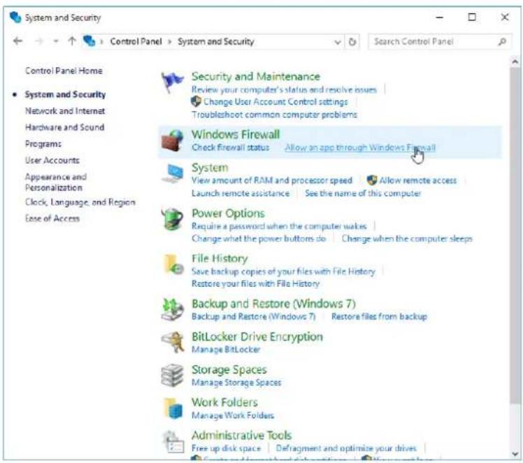
→ The "Allowed apps" window will be displayed.
Step 3
Click the [Change settings] button.

→ “Allowed apps and features:” will be displayed.
Step 4
Click the [Allow another apps...] button.

→ The "Add an app" window will be displayed.
Step 5
Click the [Browse...] button.

→ The "Browse" window will be displayed.
Step 6
Select "asm300ope.exe" and click the [Open] button.
Note:
- When installed with the ALL option in a PC on which 32-bit OS is running, the executable files, etc. will be saved on the following folder. C:¥Program Files¥Panasonic¥asm300
- When installed in a PC on which 64-bit OS is running, "Program Files" will actually be displayed as "Program Files (x86)".
Step 7
Select "asm300ope.exe", and click the [Add] button.

Step 8
Execute steps 4 - 7 in the same manner to add "asm300liveIP.exe", "asm300srv.exe", "asm300tlsrv.exe", "ASMDownloadQueue.exe", "ASDBService.exe" and "File and Printer Sharing".
Note:
- When installed with the ALL option in a PC on which 32-bit OS is running, the executable files, etc. will be saved on the following folder. asm300liveIP.exe: C:¥Program Files¥Panasonic¥asm300 asm300srv.exe: C:¥Program Files¥Panasonic¥asm300 asm300tlsrv.exe: C:¥Program Files¥Panasonic¥asm300 ASMDownloadQueue.exe C:¥Program Files¥Panasonic¥asm300 ASDBService.exe C:¥Program Files¥Panasonic¥ASM300
- When installed in a PC on which 64-bit OS is running, "Program Files" will actually be displayed as "Program Files (x86)".
Step 9
Click the [OK] button.
Set the installation method of fisheye 3.17.
cameras
Set the installation method of a camera. Configure the settings on a browser of the camera to be used, not on this software. Refer to operating instructions of the camera for how to operate.
Note:
• The following procedures are explained by taking a 3M Fisheye camera as an example. - If the installation method is changed, it is necessary to execute the preset registration again with the reconfigured installation method. - When the angle of view is changed by panning/tilting operation, images from the preset position may look be deviated since information of the angle of view is being held. To check the registered preset position, select a camera from the device tree and move the camera by selecting "HOME" of the preset position to check the angle of view by monitoring the displayed images.
When installing on a ceiling 3.17.1.
Step 1
Display the setup window of the browser of the camera to be installed on a ceiling.
Step 2
Shift to [Camera] - [JPEG/H.264] - [Image capture mode] - [ 1.3M QuadPTZ[4:3]] or [ 1.3M SinglePTZ [4:3]], and click the [Setup] button.
2M Double Panorama [16:9]
1M Double Panorama [16:9]
1.3M Quad PTZ [4:3]
1.3M Single PTZ [4:3]
Double Panorama + Quad PTZ
Double Panorama + Single PTZ
Select the following image capture mode for WV-SFN480 or WV-SFV481.
Double Panorama
Quad PTZ
Single PTZ
Select the following image capture mode for WV-S4150, WV-S4550L(M), WV-X4170, WV-X4171 or WV-X4571L(M).
Double Panorama
Quad PTZ
Single PTZ
Step 3
Select [Off] for [Upside down] under [Basic], and then click the [Setup] button.
Upside-down

On

Off
Step 4
To use the angle of view that is set on the camera, execute the preset registration here.
For how to execute the preset registration, refer to the operating instructions of the camera in use.
Step 5
Select [3M Fisheye [4:3]] or [1.3M Fisheye [4:3]] for [Image capture mode], and then click the [Setup] button.
3M Fisheye [4:3]
1.3M Fisheye [4:3]
Select the following image capture mode for WV-SFN480 or WV-SFV481.
9M Fisheye
4M Fisheye
Select the following image capture mode for WV-S4150, WV-S4550L(M), WV-X4170, WV-X4171 or WV-X4571L(M).
Fisheye
When installing on a table 3.17.2.
Step 1
Display the setup window of the browser of the camera to be installed on a table.
Step 2
Shift to [Camera] - [JPEG/H.264] - [Image capture mode] - [ 1.3M QuadPTZ[4:3]] or [ 1.3M SinglePTZ [4:3]], and click the [Setup] button.
2M Double Panorama [16:9]
1M Double Panorama [16:9]
1.3M Quad PTZ [4:3]
1.3M Single PTZ [4:3]
Double Panorama + Quad PTZ
Double Panorama + Single PTZ
Select the following image capture mode for WV-SFN480 or WV-SFV481.
Double Panorama
Quad PTZ
Single PTZ
Select the following image capture mode for WV-S4150, WV-S4550L(M), WV-X4170, WV-X4171 or WV-X4571L(M).
Double Panorama
Quad PTZ
Single PTZ
Step 3
Select [On] for [Upside down] under [Basic], and then click the [Setup] button.
Upside-down


Step 4
To use the angle of view that is set on the camera, execute the preset registration here.
For how to execute the preset registration, refer to the operating instructions of the camera in use.
Step 5
Select [3M Fisheye [4:3]] or [1.3M Fisheye [4:3]] for [Image capture mode], and then click the [Setup] button.
3M Fisheye [4:3]
1.3M Fisheye [4:3]
Select the following image capture mode for WV-SFN480 or WV-SFV481.
9M Fisheye
4M Fisheye
Select the following image capture mode for WV-S4150, WV-S4550L(M), WV-X4170, WV-X4171 or WV-X4571L(M).
Fisheye
When installing on a wall 3.17.3.
Step 1
Display the setup window of the browser of the camera to be installed on a wall.
Step 2
Shift to [Camera] - [JPEG/H.264] - [Image capture mode] - [ 1.3M QuadPTZ[4:3]] or [ 1.3M SinglePTZ [4:3]], and click the [Setup] button.
2M Panorama [16:9]
1M Panorama [16:9]
1.3M Quad PTZ [4:3]
1.3M Single PTZ [4:3]
Panorama + Quad PTZ
Panorama + Single PTZ
Select the following image capture mode for WV-SFN480 or WV-SFV481.
Panorama
Quad PTZ
Single PTZ
Select the following image capture mode for WV-S4150, WV-S4550L(M), WV-X4170, WV-X4171 or WV-X4571L(M).
Panorama
Quad PTZ
Single PTZ
Step 3
To use the angle of view that is set on the camera, execute the preset registration here. For how to execute the preset registration, refer to the operating instructions of the camera in use.
Step 4
Select [3M Fisheye [4:3]] or [1.3M Fisheye [4:3]] for [Image capture mode], and then click the [Setup] button.
3M Fisheye [4:3]
1.3M Fisheye [4:3]
Select the following image capture mode for WV-SFN480 or WV-SFV481.
9M Fisheye
4M Fisheye
Select the following image capture mode for WV-S4150, WV-S4550L(M), WV-X4170, WV-X4171 or WV-X4571L(M).
Fisheye
Operating Instructions 4. Use the operation window 4.1.
With this software, it is possible to display images on the operation window from up to 16 cameras simultaneously (up to 64 cameras by adding license of WV-ASE202). It is not only possible to display live images from cameras connected to the same recorder, but also from cameras connected to different recorders.
When the images are displayed through the recorder, the top page of the recorder is displayed. It is possible to display live images from encoders or cameras that are not registered in the recorder.
Important:
- Refer to " Compatible devices" for supported models and versions.

Note:
- Speed of image load may become slow when the processing load is too heavy on the devices or on the PC (such when many cameras are connected, when displaying live images from many cameras, etc.) or when the network traffic is heavy. • Audio and images may sometimes become out of synchronization.
- When using the live window, it is possible to display images from up to 20 cameras simultaneously (up to 68 cameras by adding license of WV-ASE202). Refer to "Use the live window" for further information.
- When network disconnection occurs while displaying live images, the images may sometimes not be displayed correctly soon after recovery.
- When the settings of the setup menu of the camera are edited while displaying live images, select the camera again.
- It is also possible to change the device tree display to the folder tree display. Refer to "Drawing and audio setup" for further information about the folder tree form display.
Search for registered device name, folder 4.1.1. name, group name and sequence name
It is possible to search for device name, folder name, group name and sequence name that is registered in this software.
Step 1
Enter a desired device name, a folder name, a group name, or a sequence name in the search field at the upper part of the function panel.

Note:
• The maximum number of characters that can be entered is 16. - Search will be executed with partial match of a name, and en space, em space, upper-case and lower-case will not be distinguished. - The operation window will become inoperable during a screen on which the search is being executed is being displayed.
→ When the search is ended, the panel including items that match the name entered in the search field will turn to orange color.

Step 2
When the panel colored in orange is clicked and opened, the search result will be displayed.
Note:
• The search result shows only items that partially matched with the name entered in the search field. • The other items will not be displayed.
Step 3
When the name entered in the search field is deleted, it returns to the previous state before the search.

Note:
- It is possible to delete the name entered in the search field by clicking the [×] button on the right side of the search field.
Confirm the registered devices 4.1.2.
The devices registered in this software can be confirmed as follows.
Step 1
Click the "Device tree" bar on the function panel.

→ The "Device tree" panel will be displayed. The registered devices will be displayed in the tree view.

When no device is registered, no device will be displayed. Only an administrator can register devices.
Step 2
Click any of a recorder icon, an encoder icon and a folder icon in the device tree.
→ The icons of the cameras registered in the recorder, the encoder or the folder will be displayed.

Note:
- Refer to " Settings relating to the device management" for the device registration.
4.1.2.1. Icons in the device tree
The following are descriptions of the icons displayed in the device tree.
| Icon Description | ||
 | Indicates NV300Indicates also a state in connection with this recorder. | |
 | Indicates NV200Indicates also a state in connection with this recorder. | |
 | Indicates HD300Indicates also a state in connection with this recorder. | |
 | Indicates ND400Indicates also a state in connection with this recorder. | |
 | Indicates HD600Indicates also a state in connection with this recorder. | |
 | NV200, NV300, NX200 or NX300Indicates also a state in connection with this recorder. | |
 | Indicates NX400Indicates also a state in connection with this recorder. | |
 | It indicates that a recorder having the failover function is monitoring an error. | |
 | It indicates that a recorder having the failover function is executing a failover. | |
 | Indicates an encoderIndicates also a state in connection with this encoder. | |
 | Indicates Video Insight ServerIndicates also a state in connection with this server. | |
 | Indicates GXE100Indicates also a state in connection with this encoder. | |
 | Indicates dome camera 1Indicates also a state in connection with this camera. | |
 | Indicates dome camera 2Indicates also a state in connection with this camera. | |
 | Indicates dome camera 3Indicates also a state in connection with this camera. | |
 | Indicates dome camera 4Indicates also a state in connection with this camera. | |
 | Indicates dome camera 5Indicates also a state in connection with this camera. | |
 | Indicates dome camera 6Indicates also a state in connection with this camera. | |
 | Indicates dome camera 7Indicates also a state in connection with this camera. | |
 | Indicates dome camera 8Indicates also a state in connection with this camera. | |
 | Indicates dome camera 9Indicates also a state in connection with this camera. | |
 | Indicates dome camera 10Indicates also a state in connection with this camera. | |
 | Indicates dome camera 11Indicates also a state in connection with this camera. | |
 | Indicates dome camera 12There are 2 types of fixed type and PTZ type.Indicates also a state in connection with this camera. | |
 | Indicates dome camera 13Indicates also a state in connection with this camera. | |
 | Indicates fixed camera 1Indicates also a state in connection with this camera. | |
 | Indicates fixed camera 2Indicates also a state in connection with this camera. | |
 | Indicates fixed camera 3Indicates also a state in connection with this camera. | |
 | Indicates fixed camera 4Indicates also a state in connection with this camera. | |
 | Indicates fisheye camera 1Indicates also a state in connection with this camera. | |
 | Indicates fisheye camera 2Indicates also a state in connection with this camera. | |
 | Indicates fisheye camera 3Indicates also a state in connection with this camera or a microphone. | |
 | Indicates an aero PTZ cameraIndicates also a state in connection with this camera. | |
 | Indicates also a state in disconnection with a recorder. | |
 | Indicates also a state in disconnection with an encoder. | |
| Icon Description | |
 | Indicates a state in disconnection with a camera or a microphone. When right-clicking on an icon, a pop-up menu will be displayed. When "Return to regular icons." is selected, it will change to the connection status display. |
 | Indicates a folder. |
*1 Sometimes, live images may not be displayed even when the camera icon indicates that it is online. In this case, the following are possible causes.
- The Panasonic alarm protocol is not ready for reception. (The Panasonic alarm protocol notification function is not active on the recorder, encoder and/or this software.)
- The recorder is currently being configured or the SD memory recording is currently being executed.
*2 If it is unable to receive the Panasonic alarm protocol notification from the recorder, the state of the camera icon will not correctly be displayed even when the camera registered in the recorder is disconnected.
4.1.2.2. Pop-up menus over the icons in the device tree
When right-clicking on the camera icon, the pop-up menu will be displayed.


■ Browser start, Camera browser start, Microphone browser start
Start the web browser to display the top page of a desired device.
When the camera icon connected to the recorder is selected, the device to be displayed differs according to the method of video acquisition.
When the images are displayed through the recorder, the top page of the recorder is displayed. When the images are displayed through the camera, the top page of the camera will be displayed.
When a linked camera is in use, the top page of the camera or the top page of the microphone will be displayed by selecting [Camera browser start] or [Microphone browser start] respectively.
Note:
- These menus will be displayed only when logged in as an administrator or a user whose user level is "LV0" or "LV1".
- Depending on the settings of the web browser, the top page may sometimes not be displayed due to the pop-up blocker. In this case, cancel the pop-up blocker on the following window.

4.1.3. Monitor images from the selected camera
When clicking a desired camera icon, images from the selected camera will be displayed. Images from the camera can be displayed in various ways; display on a 1-screen, display in the desired area, display on a full screen, etc.
Important:
- In the case of the independent camera with "Data encryption" turned on in the setting on the camera side, it is necessary to input "Encryption password" when displaying the camera image. For details on "Data encryption", read the operation manual of the camera.

- If the data encrypted camera is registered in the recorder, the encryption password input screen will not be displayed unless the "Encryption password" of the camera is changed. If you change the "Encryption password", the input screen will be displayed until you reacquire the recorder's device information on the device setup screen.
- The images of data encrypted camera can be displayed only in 1-screen, in the case of multi-screen, in the leftmost image area. When it is placed in the other area, black screen will be displayed.
• Images from encrypted cameras cannot be displayed on the live window.
- When the Video Insight Server's checkbox "Enable Security" is marked ([Administrations] - [Servers] - [Server Setup] - [Advanced] - [Server Options]), the images from Video Insight Server cannot be displayed.
4.1.3.1. Monitor images on a 1-screen
Step 1
Click the [1-screen] icon on the tool bar.
Step 2
When 1-screen display is selected, click a camera icon from which you desired to monitor images.
→ Images from the selected camera will be displayed on a 1-screen.

- When right-clicking on the displayed image, the pop-up menu will be displayed and "Save as JPEG file", "Print" and "EL-zoom" are available.
When “Quad PTZ” is selected for the image capture mode of the fisheye camera in use, it is possible to display images on 4-screen.

- It is also possible to display images from a desired camera by dragging and dropping the corresponding camera icon onto the image display area.
- When displaying images on a multi-screen, it is possible to switch from the multi-screen and display images on 1-screen by clicking the selected area on the multi-screen. However, the camera image cannot be double-clicked while the sound collection position of the microphone is displayed or the microphone setting panel is displayed.
4.1.3.2. Specify the area to display images
Step 1
Set to [Display format when selecting camera] for [Setup screen] - [Drawing and audio setup] - [Display format when selecting camera].
Step 2
Set to any of 2A-screen, 2B-screen, 3A-screen, 3B-screen, 3C-screen, 4-screen, 4A-screen, 4B-screen, 4C-screen, 4D-screen, 4E-screen, 5-screen, 6-screen, 6A-screen, 7-screen, 7A-screen, 9-screen, 10-screen, 13-screen, 16-screen, 25-screen, 36-screen, 49-screen and 64-screen display (25-/36-/49-/64-screen will become available when WV-ASE202 license is added. Refer to “Switch the pattern of the screen” for further information) and click a desired area to monitor.
→ The frame will be displayed around the selected area to indicate the current selection.
Step 3
Click a camera icon from which you desired to monitor images.
→ Image from the selected camera will be displayed in the selected area.

Note:
- It is also possible to display images from a desired camera by dragging and dropping the corresponding camera icon onto the image display area.
- It is also possible to change the area to the other by dragging and dropping the image currently being displayed onto a desired area. However, it is impossible to drag images from the camera while the sound collection position of the microphone or the microphone setting panel is being displayed.
- It is also possible to switch the display area by dragging and dropping the icons of "recorder", "encoder" and "folder" onto the image display area. • The whole images will be redrawn after the drag and drop operation.
4.1.3.3. Switch the pattern of the screen
Switch the image display area to a multi-screen (1/4/9/16/25/36/49/64) and display live images from cameras or recorded images on a recorder.
Note:
• It is necessary add a license of Extension Software WV-ASE202 to display in 25-screen or more.
Step 1
Click the [1] - [64] icon on the tool bar.

→ The images will be displayed on the selected screen pattern.
The details of the icon are as follows.
| Icon Description | |
 | Display images on 1-screen. |
 | Display images on 2A-screen. |
 | Display images on 2B-screen. |
 | Display images on 3A-screen. |
 | Display images on 3B-screen. |
 | Display images on 3C-screen. |
 | Display images on 4-screen. |
 | Display images on 4A-screen. |
 | Display images on 4B-screen. |
 | Display images on 4C-screen. |
 | Display images on 4D-screen. |
 | Display images on 4E-screen. |
 | Display images on 5-screen. |
 | Display images on 6-screen. |
 | Display images on 6A-screen. |
 | Display images on 7-screen. |
 | Display images on 7A-screen. |
 | Display images on 9-screen. |
 | Display images on 10-screen. |
 | Display images on 13-screen. |
 | Display images on 16-screen. |
The following are available after the license for the WV-ASE202 is added.
| Icon Description | |
 | Display images on 25-screen. |
 | Display images on 36-screen. |
 | Display images on 49-screen. |
 | Display images on 64-screen. |
Note:
- When displaying images on a multi-screen, it is possible to switch from the multi-screen and display images on 1-screen by clicking the selected area on the multi-screen. However, the camera image cannot be double-clicked while the sound collection position of the microphone is displayed or the microphone setting panel is displayed.
- 4M-screen is not displayed on the screen layout of the toolbar of the operation monitor because it is a layout dedicated to group display where only the multi-sensor camera can be placed.
4.1.3.4. Display magnified images
When the screen pattern is switched from 16-screen to 4A-screen, 4B-screen, 4C-screen or 4D-screen, images to be displayed will be as follows.
Group display on 16-screen
| 1 | 2 | 3 | 4 |
| 5 | 6 | 7 | 8 |
| 9 | 10 | 11 | 12 |
| 13 | 14 | 15 | 16 |

Group display on 4-screen
| 1 | 2 |
| 5 | 6 |
Group display on 16-screen
| 1 | 2 | 3 | 4 |
| 5 | 6 | 7 | 8 |
| 9 | 10 | 11 | 12 |
| 13 | 14 | 15 | 16 |

Group display on 4-screen
| 3 | 4 |
| 7 | 8 |
Group display on 16-screen
| 1 | 2 | 3 | 4 |
| 5 | 6 | 7 | 8 |
| 9 | 10 | 11 | 12 |
| 13 | 14 | 15 | 16 |

Group display on 4-screen
| 9 | 10 |
| 13 | 14 |
Group display on 16-screen
| 1 | 2 | 3 | 4 |
| 5 | 6 | 7 | 8 |
| 9 | 10 | 11 | 12 |
| 13 | 14 | 15 | 16 |

Group display on 4-screen
| 11 | 12 |
| 15 | 16 |
When the screen pattern is switched from 64-screen to 4A-screen, 4B-screen, 4C-screen or 4D-screen, images to be displayed will be as follows.
Group display on 64-screen
| 1 | 2 | 3 | 4 | 5 | 6 | 7 | 8 |
| 9 | 10 | 11 | 12 | 13 | 14 | 15 | 16 |
| 17 | 18 | 19 | 20 | 21 | 22 | 23 | 24 |
| 25 | 26 | 27 | 28 | 29 | 30 | 31 | 32 |
| 33 | 34 | 35 | 36 | 37 | 38 | 39 | 40 |
| 41 | 42 | 43 | 44 | 45 | 46 | 47 | 48 |
| 49 | 50 | 51 | 52 | 53 | 54 | 55 | 56 |
| 57 | 58 | 59 | 60 | 61 | 62 | 63 | 64 |
Group display on 4-screen
| 1 | 2 |
| 9 | 10 |
Group display on 64-screen
| 1 | 2 | 3 | 4 | 5 | 6 | 7 | 8 |
| 9 | 10 | 11 | 12 | 13 | 14 | 15 | 16 |
| 17 | 18 | 19 | 20 | 21 | 22 | 23 | 24 |
| 25 | 26 | 27 | 28 | 29 | 30 | 31 | 32 |
| 33 | 34 | 35 | 36 | 37 | 38 | 39 | 40 |
| 41 | 42 | 43 | 44 | 45 | 46 | 47 | 48 |
| 49 | 50 | 51 | 52 | 53 | 54 | 55 | 56 |
| 57 | 58 | 59 | 60 | 61 | 62 | 63 | 64 |

Group display on 4-screen
| 3 | 4 |
| 11 | 12 |
Group display on 64-screen
| 1 | 2 | 3 | 4 | 5 | 6 | 7 | 8 |
| 9 | 10 | 11 | 12 | 13 | 14 | 15 | 16 |
| 17 | 18 | 19 | 20 | 21 | 22 | 23 | 24 |
| 25 | 26 | 27 | 28 | 29 | 30 | 31 | 32 |
| 33 | 34 | 35 | 36 | 37 | 38 | 39 | 40 |
| 41 | 42 | 43 | 44 | 45 | 46 | 47 | 48 |
| 49 | 50 | 51 | 52 | 53 | 54 | 55 | 56 |
| 57 | 58 | 59 | 60 | 61 | 62 | 63 | 64 |

Group display on 4-screen
| 17 | 18 |
| 25 | 26 |
Group display on 64-screen
| 1 | 2 | 3 | 4 | 5 | 6 | 7 | 8 |
| 9 | 10 | 11 | 12 | 13 | 14 | 15 | 16 |
| 17 | 18 | 19 | 20 | 21 | 22 | 23 | 24 |
| 25 | 26 | 27 | 28 | 29 | 30 | 31 | 32 |
| 33 | 34 | 35 | 36 | 37 | 38 | 39 | 40 |
| 41 | 42 | 43 | 44 | 45 | 46 | 47 | 48 |
| 49 | 50 | 51 | 52 | 53 | 54 | 55 | 56 |
| 57 | 58 | 59 | 60 | 61 | 62 | 63 | 64 |

Group display on 4-screen
| 19 | 20 |
| 27 | 28 |
4.1.3.5. Image display method
It is possible to select how to display the image display area on the setup window. Refer to "Drawing and audio setup" for further information.
■ "Aspect ratio" mode
Images will be displayed in the selected area while keeping its aspect ratio and outside the displayed image will be displayed as black bands.
The following are the examples when the aspect ratio of displayed images is 4:3.

■ "Aspect ratio (type 2)" mode
Images will be displayed in the selected area while keeping their aspect ratio, and the area outside the displayed image
will be displayed as black bands.
It is possible to display images with a size larger than the aspect ratio, but this increases the CPU load.
Note:
• Images from the HD300 will be enlarged/reduced even in the aspect ratio mode. - As for the aspect ratio, the setting descriptions are the same as "Aspect ratio" and "Aspect ratio (type 2)" of "Image display method". • Images from the Video Insight Server will be enlarged/reduced even in the aspect ratio mode.
■ "Scaling" mode
Display enlarged/reduced images in the whole screen of the selected area.
■ "Pixel by Pixel" mode
Images will be displayed in the same image capture size specified on the camera. Adjustment will be required between the resolution of the images from the camera and the display window size. See the following example.
When the display window size is larger than the image from the camera

When the display window size is smaller than the image from the camera

Note:
- When the display window size is smaller than the image from the camera, the area of the image that is not displayed can be moved to the center of the display area by click operation on the display area. In this case, panning/tilting operation will be performed together with this operation when using the PTZ camera or the fisheye camera with Single PTZ/Quad PTZ display.
- An image to be saved as a still picture or an image to be printed will be output with the display window size.
- An image to be saved as a BMP image will be saved in the resolution that is used to transmit from the camera.
- This operation is available on 1-/4-/9-/16-screen. When operating on 25-/36-/49-/64-screen, the aspect ratio will be applied.
- When using in the same size display mode, the [Mic setup] button and the microphone setting panel will not be displayed and sound collection will also not be performed.
- The image selection frame border in the area will not be displayed when images are being displayed in "Quad PTZ".
- Images will be displayed in the actual size when displaying images on 1-screen, the left of 3A-screen or the right of 3B-screen. Depending on the image capture size of images to display on a screen pattern other than above, image quality may become lower than the actual image quality since the image capture size is reduced.
4.1.3.6. Monitor images on a full screen
Step 1
Images from the camera will be displayed in this area.
→ Refer to "Monitor images from the selected camera" for how to display images.
Step 2
When 1-screen display is selected, click a camera icon from which you desired to monitor images.
→ Images from the selected camera will be displayed on a 1-screen.
Note:
- It is also possible to display recorded images on a full screen. Playback on a full screen is available only at normal playback speed (1x) and reverse playback is unavailable.
Step 3
Click the [Full screen display] icon on the tool bar or select [Full screen display] on the menu, or select [Full screen display] from the right-click menu.

→ When it is in progress of shifting to the full screen display, the "shifting mark" will be displayed. When shifting to the full screen display is completed, the image arrangement area and the information display section will be displayed over the entire display screen.


Step 4
When [Return] is selected from the right-click menu, the screen size will return to the normal size after displaying the "shifting mark".
Note:
- When load to the devices and the PC is heavy (such as when many cameras are connected or when number of live image display screens is many) or depending on the network environment, screen shifting speed may become slow.
Use the fisheye image display change 4.1.4. function
Live images or recorder playback images can be displayed in any of Single PTZ, Quad PTZ, Panorama and Double panorama format.
Note:
• The display change function will be valid only when the following settings are applied to the camera.
| Fisheye camera | Image capture mode | Resolution |
| 9M Fisheye cameras | 9M Fisheye8M Fisheye4M Fisheye | Fisheye/2992×2992Fisheye/2816×2816Fisheye/2192×2192Fisheye/2048×2048Fisheye/1280×1280 |
| 5M Fisheye cameras | 5M Fisheye | Fisheye/2192×2192Fisheye/1280×1280 |
| 3M Fisheye cameras | 3M Fisheye [4:3]1.3M Fisheye [4:3] | Fisheye/2048×1536(Unavailable for H.264)Fisheye/1280×960 |
• Refer to the operating instructions of the camera in use for how to configure the settings. • This function is available when the camera in use is the fisheye camera. • This function is available with the following monitor:
- When an option of WV-ASE202 is not added: Operation window/Live window
- When an option of WV-ASE202 is added: Operation window/Live window 1
- The number of screen divisions that can use this function is 1-screen, 2A-screen, 2B-screen, 4-screen, on left area of 3A-screen, on right area of 3B-screen, and on large area of 7-/10-/13-screen.
- With the following versions of fisheye cameras, this function is not available with the SD recorded images. This function is available only for live images or recorder playback images.
● 3M fisheye camera: All version ● WV-SFN480, WV-SFV481: Below Ver. 2.52
- When images are being displayed in any of Single PTZ, Quad PTZ, Panorama and Double panorama format, the [Microphone setup] button, the microphone setup panel and the sound collection position will not be displayed. Audio will be played according to the microphone setting for "Fisheye".
- When displaying a 2048x2048 or larger fisheye image in the panorama or double panorama format, a frame rate lower than the value set on the camera may be displayed.
- When a fisheye image of 2992x2992 size is being received at 30 fps, a frame rate lower than the set value at the camera side will be displayed.
- When this function is in use, a face frame and AVMD information will be displayed on the fisheye image before conversion.
4.1.4.1. Display fisheye images in the Single PTZ or Quad PTZ format
Step 1
Images from the camera will be displayed in this area.
→ Refer to "Monitor images from the selected camera" for how to display images.
Step 2
Display a pop-up window by right-clicking on received images on the selected area.
Select a display format by moving the cursor onto [Fisheye display menu].
The following are examples of how to use this function.
Distortion correction is applied to one point of a fisheye image, and the corrected image is displayed as a 4:3 image with the angle of view registered in preset 1.
You can move the image so that a desired point becomes the center by clicking on that point. (Click centering)
You can also change the display position on the screen by displaying and operating the fisheye control screen.
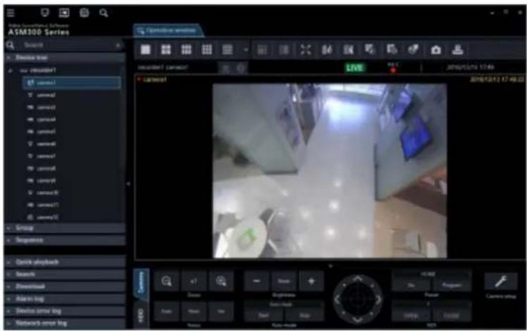
Distortion correction is applied to four points of a fisheye image, and the corrected images are displayed with the angles of view registered in presets 1 through 4.
You can move the image so that a desired point becomes the center by clicking on that point. (Click centering)
You can also change the display position on the screen by displaying and operating the fisheye control screen.

Note:
- When "Recorder" is selected for the "Live source" setting of the fisheye camera registered in the recorder, the preset positions are displayed as shown in the diagram below. You can change the position displayed on the screen using the fisheye control.

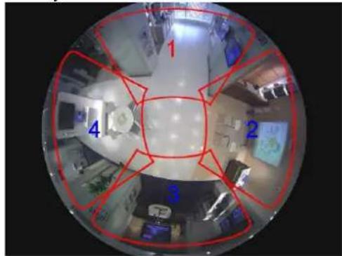
- When "Single PTZ" or "Quad PTZ" is selected for "Fisheye display menu", "Auto pan", "Preset sequence", and "Preset position registration" are not supported. For recorded images, "Brightness" is not supported.
- When the drag zoom function is in use, the drag zoom operation may sometimes become slow due to processing load.
4.1.4.2. Display fisheye images in the Panorama format
Step 1
Images from the camera are displayed in this area.
→ Refer to "Monitor images from the selected camera" for instructions on how to display images.
Step 2
Display a pop-up window by right-clicking on received images on the selected area.
Select a display format by moving the cursor onto [Fisheye display menu].
The following are the examples when using this function.
The distortion correction will be applied to an image at the center of a fisheye image and the corrected image displayed in the panorama format.

Note:
- When "Image rotation" of the right-click menu is selected on a received image of the selection area, the display position of panorama image can finely be adjusted.
- When the drag zoom function is in use, the drag zoom operation may sometimes become slow due to processing load.
4.1.4.3. Display fisheye images in the Double Panorama format
Step 1
Images from the camera will be displayed in this area.
→ Refer to "Monitor images from the selected camera" for how to display images.
Step 2
Display a pop-up window by right-clicking on received images on the selected area.
Select a display format by moving the cursor onto [Fisheye display menu].
The following are examples of using this function.
The distortion correction is applied to each of the 180° images that are halves of the fisheye image, and the corrected image is displayed in panorama format. It is possible to move an image with a desired point as the center by clicking a point to be positioned as the center of the image (click centering). At this time, both the upper and lower panorama images will simultaneously move in the horizontal direction.

Note:
- When "Image rotation" in the right-click menu is selected on a received image in the selection area, a double panorama image can be flipped upside down.
- When the drag zoom function is in use, the drag zoom operation may sometimes become slow due to processing load.
4.1.4.4. Use the fisheye control
Step 1
Display a pop-up window by selecting [Fisheye Control] from the right-click menu displayed when right-clicking on received images in the selected area, or select [Fisheye Control] on the toolbar.
The following are examples of using the cropping function.


On this screen, it is possible to change the display position using the correction function.
By dragging and dropping a number icon of a screen whose display position is to be changed, that position will become the center of display.
Note:
- Depending on the position of the number icon, it may not be exactly the center of the images to be displayed. • The refresh interval of fisheye control images is 1 second.
Use cropping function 4.1.5.
Cropping is a function that makes images easier to see by cropping a part or 5 parts on a panorama image. The live images or playback images can be displayed with "5 cropping" or "1 cropping" image.
Note:
• This function is available with 7-series cameras (Version 1.06 or later). - The following cameras support this function:
| Camera | Image capture mode | Resolution |
| 7-series cameras (Version 1.06 or later) | 8M/30 fps | 4000×3000 |
| 8M/15 fps | 2560×1920 | |
| 12M | 2048×1536 | |
| 5M | 3840×2160 | |
| 4M | 2560×1440 | |
| 1920×1080 | ||
| V-series cameras | 4000x3000 | 4000×3000 |
| 5M | 2560×1920 | |
| 3M | 2048×1536 | |
| 3840x2160 | 3840×2160 | |
| 1080P | 1920×1080 | |
| Multi-sensor cameras 4:3 mode | 3840x2160 | |
| 2560x1440 | ||
| 1920x1080 | ||
| WV-S1550L | 4:3 mode | 3072x2304 |
| WV-S2250L | 16:9 mode | 2560x1920 |
| WV-S2550L | 3072x1728 | |
| 2560x1440 | ||
| 1920x1080 | ||
| WV-S1570L | 16:9 mode | 3840x2160 |
| WV-S2270L | 2560x1440 | |
| WV-S2570L | 1920x1080 | |
| 2160x3840 | ||
• Refer to the operating instructions of the camera in use for how to configure the settings.
4.1.5.1. Display with 5 cropping/1 cropping areas
Step 1
Images from the camera will be displayed in this area.
→ Refer to "Monitor images from the selected camera" for how to display images.
Note:
• The playback images can also be displayed with "5 cropping" or "1 cropping" image.
Step 2
Click the [5 Cropping] icon or the [1 Cropping] icon on the tool bar.
Note:
• It is disabled during visibility enhancement is processed. - It is disabled in the same size display mode.
The following are the examples when using the cropping function.
When "5 Cropping" is selected
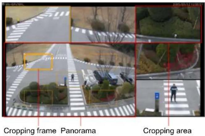
When "1 Cropping" is selected

- Operation on the panorama image The position or size to be displayed in the cropping area can be changed by drag-and-drop of the displayed cropping frame into a desired place.
- Operation on the cropping area When a point in the selected cropping area is clicked, the display position will move to locate the clicked point as the center point. Zooming out/in of the displayed image is available by scrolling the mouse wheel.
Note:
• The cropping function is available only in the operation window. - The position of the cropping area will be maintained until the next time when the same camera is selected and images from it are displayed. However, the default may be restored when the camera setting is changed.
- The display format of panorama is subject to the settings of "Image display method" ("Aspect ratio", "Scaling") of the setup window. • The cropping function displays images at 15 fps at maximum.
- When the functions of saving still picture or printing is used, the images will be output in the cropping frame.
- When an operation to zoom out/in an image is performed at an edge of the cropping area, the center point of the image being displayed in the cropping frame may deviate from the exact center point.
- When connecting multiple displays, if the operation window is placed on the left or upper display relative to the main display, the mouse wheel zooming of the cropping area will not work.
The following is the Windows display settings in which the mouse wheel zooming does not work:
Example 1: When setting the operation window at display [2] on the left side of the main display [1].

Example 2: When setting the operation window at display [2] on the upper side of the main display [1].

Display images from the cameras registered 4.1.6. as a group (group display)
By registering frequently monitored cameras as a group, images from the cameras can be displayed by unit of the registered group.
Step 1
Click the "Group" bar on the function panel.

→ The "Group" panel will be displayed.
The name of the registered group and the group icon that indicates the selected multi-screen will be displayed.
■ Registered group
The registered groups will be displayed in list form. Only groups available for the login user will be displayed. Only an administrator can register the cameras as groups. Refer to "Set a displayable group" for further information.
■ Group icon (Group name)
The group icon indicates the number of areas and the group name indicates the name of the corresponding group. When clicking the icon, images from the selected group will be displayed in the image display area.
| Icon Description | |
 | Display images on 1-screen. |
 | Display images on 2A-screen. |
 | Display images on 2B-screen. |
 | Display images on 3A-screen. |
 | Display images on 3B-screen. |
 | Display images on 3C-screen. |
 | Display images on 4-screen. |
 | Display images on 4E-screen. |
 | Display images on 5-screen. |
 | Display images on 6-screen. |
 | Display images on 6A-screen. |
 | Display images on 7-screen. |
 | Display images on 7A-screen. |
 | Display images on 9-screen. |
 | Display images on 10-screen. |
 | Display images on 13-screen. |
 | Display images on 16-screen. |
 | Display images on 4M-screen. 4M-screen can be set only for multi-sensor camera. Cameras other than multi-sensor cameras cannot be placed. |
The following are available after the license for the WV-ASE202 is added.
| Icon Description | |
 | Display images on 25-screen. |
 | Display images on 36-screen. |
 | Display images on 49-screen. |
 | Display images on 64-screen. |
Step 2
Click the desired group icon.
→ Live images from the cameras registered in the group will be displayed in the image display area.
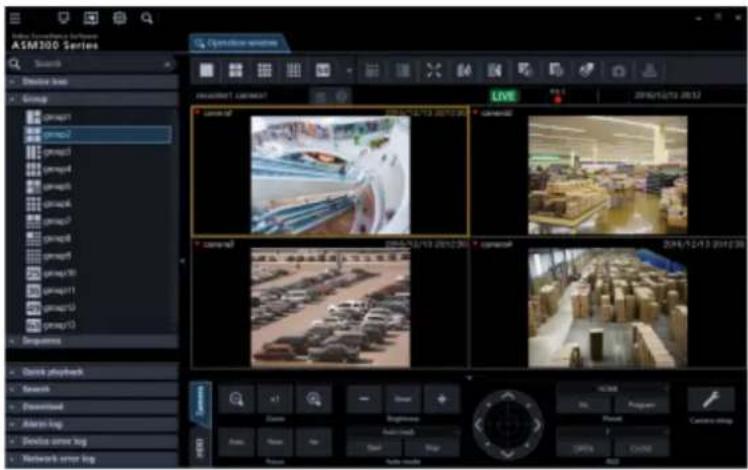
Note:
- During the 4M group display, the name of the camera in the area with the selection frame is displayed in the information display area. Also, the border dividing each area will be hidden.
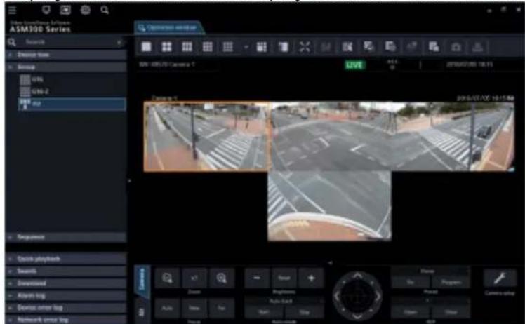
Switch groups automatically and display 4.1.7. images from each group sequentially (sequence)
Images from the registered groups can be displayed on a full screen in an automatic sequential manner. It is possible to set the dwell time (sequence interval) for the sequence display.
Note:
- Actual dwell time may become longer than the set dwell time when the processing load is too heavy on the devices or on the PC (such as when many cameras are connected, when displaying live images from many cameras, etc.) or when the network traffic is heavy.
- Images may sometimes not be displayed during the sequence display depending on the network environment.
- It is recommended to use less than 10 recorders when using the sequence display. • Display with "5 Cropping" or "1 Cropping" is unavailable during the sequence display.
Step 1
Click the "Sequence" bar on the function panel.
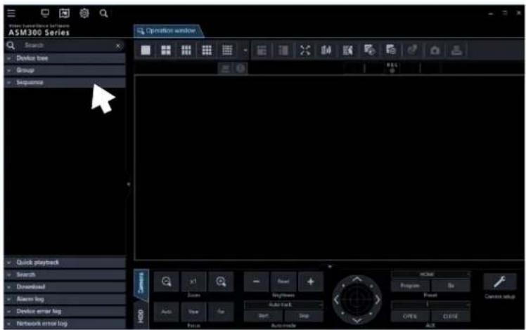
→ The "Sequence" panel will be displayed.

■ Sequence dwell time
Select a sequence dwell time from the following.
3s/ 5s/ 10s/ 15s/ 20s/ 25s/ 30s/ 35s/ 40s/ 45s/ 50s/ 55s/ 1min
Default: 3s
Note:
- "Sequence dwell time" is the duration from the moment when completing displaying of all images from the cameras registered as a group till the moment when starting displaying images of the next group.
■ Registered sequence
The registered sequences will be displayed in list form.
When a desired sequence is selected, the sequence display will start with the selected dwell time.
The registration sequence is created on the setup window by an administrator.
Refer to "Set a displayable sequence" for further information.
Step 2
Set the sequence dwell time and select [Sequence].
→ The window will switch to full screen and the sequence display will start.

Step 3
To stop the sequence display, right-click and select [Back] from the right-click menu. When the sequence display is stopped, the full screen will return to the normal window size and live image display will start.
Device operation 4.1.8.
Important:
- Check if the model in use is compatible with each function.
- To operate the newly registered camera and microphone, restart this software before starting operation.
4.1.8.1. Operate the cameras
It is possible to execute camera operations such as display position adjustment, zoom, and focus adjustment during live image display. It may be impossible to operate the camera depending on the model of the connected camera.
Refer to "Compatible devices" for the supported cameras.
This software can operate the following.
- Panning/tilting (*1): Adjusts the horizontal/vertical position of images from the camera.
- Zoom (*3): Zooms in/out the displayed image. • Focus: Adjusts the focal point of images from the camera. • Brightness: Adjusts the lens iris.
- Preset function (*1) (*4): Moves the camera to the preset position registered in advance. Registration of the preset positions is also available.
• Auto mode (*1) (*2): Executes the selected auto mode function. - AUX (*2): Turns the device connected to the AUX terminal to the open state or the close state.
*1 Available for PTZ cameras and fisheye cameras. Also, this function is disabled when WV-X6533LN/WV-S6532LN is set into the "Insert/Remove SD memory card" mode.
*2 When using Video Insight Server, this function is unavailable regardless of the camera model.
*3 When using Video Insight Server, [x1] button is not available.
*4 When using Video Insight Server, [Go] button and [Program] button for the preset position "Home" are not available.
Note:
- Some functions may be unavailable depending on the model of the camera. Contact your dealer for further information.
- When using a camera registered for camera categories of NV200 and NV300 with this software, some operations may be restricted depending on the model of the camera. When using NV200 or NV300, register the camera on "Easy start".
Step 1
Display live images.
→ Refer to "Monitor images from the selected camera" for the live image display.
When displaying images on a multi-screen, click the desired area to select the camera to be operated.
The selected area will be displayed with the frame in orange.
Step 2
Click the [Camera] tab.
The camera operation panel will be displayed.

Step 3
Operate the camera using the buttons on the camera operation panel.
Refer to "Camera operation panel" for descriptions about the buttons.
Note:
• It is possible to pan/tilt the camera by clicking a point on the screen. Zooming is available using the wheel on the wheel mouse. By specifying an area to display desired images by dragging on the screen, the camera will move to the position making the specified area as the center and the zoom ratio will be automatically adjusted. (Drag & zoom function)
4.1.8.2. Operate the microphones
It is possible to configure the settings for sound collection position or compensation for the microphone while displaying live images from a linked camera or playback images of the recorder.
It may be impossible to operate the microphone depending on the model of the connected microphone. Refer to "Compatible devices" for the supported microphones.
This software can operate the following.
• Sound collection position: Sets a position from where the sound is picked up. Noise reduction: Reduces noise contained in the audio from microphones. Voice clearness: Selects the audio compensation level for the microphone in order to make better sound.
Note:
• The sound collection position can be set per devices displayed in the device tree. - The setting of the sound collection position is available per groups. However, the setting will be switched to each device, if a device is selected in the device tree, a camera is selected, the number
of screen setting is changed, or full screen display is performed.
- In the following cases, the [Mic setup] button will not be displayed. Audio collection will also not be performed. The sound collection position will not be displayed in the following cases even if the display setting of the sound collection position setting is "ON".
- When the fisheye camera and the microphone are not linked
- When the microphone is disabled
- When the image capture mode of the fisheye camera is not set to "Fisheye" nor "Panorama"
- When “OFF” is selected for “Audio” of “Drawing and audio setting” under “System” on the setup window
- When displaying images in more than 25-screen
- When a microphone is set on a screen other than the upper left
- When operated by a user who is not authenticated to configure the microphone setting
- When the image display method is the same size display
- When "ON" is selected for "Quad streams" on the setting of the fisheye camera
- In the following cases, the sound collection position will not be displayed even if the display setting of the sound collection position setting is "ON".
- When the EL-zoom ratio is other than x1
- When the sequential display is enabled
Step 1
Display images from a linked camera.
→ Refer to "Monitor images from the selected camera" for the live image display. → Refer to "Play" for how to display images on the recorder.
Step 2
Press the [Mic setup] button.
→ The microphone setting panel will be displayed.

Step 3
Operate the microphone using the buttons on the microphone setting panel.
Refer to "Camera operation panel" for descriptions about the buttons.
Camera image pan/tilt operation 4.1.9.
Adjust the horizontal/vertical position of the displayed camera image.
- The pan/tilt of the PTZ camera is operable regardless of the number of screens. Also, this function is disabled when WV-X6533LN/WV-S6532LN is set into the "Insert/Remove SD memory card" mode.
- The operable number of screens in the fisheye camera pan/tilt operation differs depending on the fisheye display mode.
- When clicking on an image that is being zoomed or being displayed in the pixel by pixel mode, the image will be displayed while locating the clicked point at the center of the screen. However, when clicking on an image from a PTZ camera or a fisheye camera that is being displayed on [Single PTZ], the image will not be positioned with the clicked point as the center of the screen since the pan/tilt
The function will be performed by clicking under the above condition.
The following is the availability of the pan/tilt operation per camera: (○: available / ×: not available)
| Camera type | Operation panel (*1) | Click centering |
| Fixed camera | × × | |
| PTZ camera | ○ ○ |
| Image capture mode | Fisheye display mode | Operation panel (*1) | Click centering |
| Fisheye camera | Fisheye × × | ||
| Single PTZ ○ ○ | |||
| Quad PTZ ○ ○ | |||
| Panorama × × | |||
| Double Panorama × ○ | |||
| Single PTZ ○ ○ | |||
| Quad PTZ ○ ○ | |||
| Panorama × × | |||
| Double Panorama × × | |||
| Quad streams | × × | ||
(*1): Pan/tilt operation from [Camera operation panel] - [Control pad] (Camera operation panel).
4.1.10. Camera image zoom operation
Zoom in/out the displayed image.
- The zooming operation using the operation panel of the PTZ camera and using a mouse wheel are available regardless of the number of screens. The drag-zooming and EL-zooming from the pop-up menu are available only for 1-screen display. • The zooming operation of the fixed camera and fisheye camera are all EL-zooming.
- The EL-zooming of the fixed camera is available only for 1-screen display. The operable number of screens in the EL-zooming of the fisheye camera differs depending on the fisheye display mode.
The following is the availability of the zoom operation per camera: (○: available / ×: not available)
| Camera type | Operation panel (*1) | Drag zoom | Mouse wheel zooming | Pop-up menu (*2) |
| Fixed camera | × | ○ / × (*3) | ○ / × (*3) | × |
| PTZ camera | ○ | ○ / × (*3) | ○ | ○ |
| Image capturemode | Fisheye displaymode | Operation panel(*1) | Drag zoom | Mouse wheelzooming | Pop-up menu(*2) |
| Fisheye camera | Fisheye × × × ○ | ||||
| Single PTZ | ○ | ○ / × (*3) | ○ | × | |
| Quad PTZ | ○ | ○ | ○ | × | |
| Panorama × ○ ○ | × | ||||
| Double Panorama × | ○ ○ × | ||||
| Single PTZ | ○ | ○ / × (*3) (*4) | ○ ○ | ||
| Quad PTZ | ○ | ○ / × (*3) (*4) | ○ × | ||
| Panorama | × × × ○ | ||||
| Double Panorama | × × × ○ | ||||
| Quad streams | × × × ○ | ||||
(*1): Zooming operation from [Camera operation panel] - [Zoom] (→Camera operation panel). (*2): Zooming operation using the pop-up menu [EL-zoom] to be displayed by right-clicking on the image display area of the operation monitor (Pop-up menu). (*3): It is not supported in the "Pixel by Pixel" mode. It corresponds only for the "Aspect ratio" mode and "Scaling" mode. (*4): It is not available when "Live image source" is recorder. It is available only when the camera direct reception is selected or registered as a stand-alone camera.
4.1.11. Set the preset position name
Set the preset position name of the camera.
Note:
- The position name cannot be set if logged in by the user without authority to set the preset position name.
- The names of the preset position and AUX terminal set with this software will be used only within this software and not applied to the settings of the camera side. • Position [HOME] cannot change the name.
- With the camera where the recorder is already registered, the preset position name and the AUX terminal name will be initialized, if the device information is obtained after changing the registered channel of the recorder.
Step 1
Display the camera image whose position name is to be set.
→ Refer to "Monitor images from the selected camera" for the live image display.
Step 2
Select a position whose name is to be changed from the [Preset] pull-down menu in the camera operation panel.
→ The pull-down menu is closed and the selected position is displayed.

Step 3
Right-click on the [Preset] pull-down menu in the camera operation panel, and select [Edit].

→ The Preset ID editing window will be displayed.

Step 4
Edit the position name.
Note:
• Enter 1 - 20 characters for the position name.
Step 5
Click the [OK] button.
The setting is saved and the Preset ID editing window closes.
4.1.12. Set the AUX terminal name
Set the AUX terminal name of the camera.
Note:
- The AUX terminal name cannot be set if logged in by a user without authority to set the terminal name.
- The names of the preset position and AUX terminal set with this software will be used only within this software and not applied to the settings on the camera side.
- With a camera where the recorder is already registered, the preset position name and the AUX terminal name will be initialized if the device information is obtained after changing the registered channel of the recorder.
Step 1
Display the camera image whose terminal name is to be set.
→ Refer to "Monitor images from the selected camera" for the live image display.
Step 2
Select a terminal whose name is to be changed from the [AUX] pull-down menu in the camera operation panel.
→ The pull-down menu closes and the selected terminal is displayed.

Step 3
Right-click on the [AUX] pull-down menu in the camera operation panel, and select [Edit].

The terminal name editing window will be displayed.

Step 4
Edit the terminal name.
Note:
• Enter 1 - 20 characters for the terminal name.
Step 5
Click the [OK] button.
The setting is saved and the terminal name editing window will be closed.
Record/Play using a recorder 4.1.13.
4.1.13.1. Play
It is possible to play recorded images stored on the recorder using the operation window of this software.
Note:
- Speed of image load may become slow when the processing load is too heavy on the recorder or on the PC (such as when many cameras are connected, when displaying many recorded images, etc.) or when the network traffic is heavy.
- When playing recorded images on a multi-screen, sometimes the recording time synchronization of the displayed recorded images may not be performed.
- Recorded audio can be played depending on recorder model. • Audio will be output only when playing images forward at 1x speed. • Audio may be interrupted depending on the network environment. • Audio and images may sometimes become out of synchronization.
- When there is no image recorded by the selected camera, a black screen will be displayed.
- When displaying and playing images from a camera that is not registered in the recorder, a black screen will be displayed.
- Even after the license for the WV-ASE202 is added and while live images are being displayed on a 25-screen or more, the maximum number of areas (multi-screen pattern) will become 16-screen after recorded images are displayed.
- When audio of the network microphone is not played, check if the "Mic input" or "Interactive(Full-duplex)" is selected for the "Audio transmission/reception" of the linked camera.
- When the camera selection is changed during playback while "ON" is selected for "Resume playback at camera switching", the playback of images from the newly selected camera will start from a point at the same playback time of the playback of images from the previously selected camera when the camera is switched since the playback time is taken over even though the camera is switched. When "OFF" is selected, live images from the newly selected camera will be displayed. Refer to "Basic setup" for further information about the settings.
- When playing recorded images using Video Insight Server, due to image buffering, the image refresh interval may become 1 second or playback may pause regardless of the frame rate specified for recording.
- When the Video Insight Server's checkbox "Enable Security" is marked ([Administrations] - [Servers] - [Server Setup] - [Advanced] - [Server Options]), the images from Video Insight Server cannot be displayed.
Step 1
Display live images.
→ Refer to "Monitor images from the selected camera" for the live image display.
Step 2
Click the [HDD] tab.
→ The playback operation panel will be displayed.

Step 3
Click the [PLAY] button.

Live images will be switched to playback images. The live indication displayed in the information display area will turn to the playback indication.
Note:
- Playback will start from the latest recorded image.
Step 4
To stop playback, click the [STOP] button.
Live images will be displayed in the image display area where playback images are being displayed. The playback indication displayed in the information display area will turn to the live indication.
Note:
- Operate the playback images using the buttons on the playback operation panel.
- Refer to "Playback operation panel" for descriptions about the buttons.
Restrictions during playback 4.1.13.1.1.
continuation
The following restrictions will be applied to the "Resume playback at camera switching" function. Please use this function after understanding the content. Refer to "Basic setup" for further information about the settings.
- Before changing to playback, live images will be displayed temporarily. At this time, a black screen may be displayed due to the disconnection of the camera with the recorder or the exceeding number of users. Though this momentary live image display may not occur when displaying images on a multi-screen, the [Status] icon on the information display area may change to [Live] for a moment.
users. Though this momentary live image display may not occur when displaying images on a multi-screen, the [Status] icon on the information display area may change to [Live] for a moment.
- If recording of images from the newly selected camera is not performed in the same period when recording of images from the previously selected camera, images recorded at a totally different time may be played or a paused image may be displayed at the end of playback.
- When the newly selected camera is not connected with the recorder, a black screen will appear.
- The "Resume playback at camera switching" function remains valid even when the camera is changed by the following operations. When a camera not connected with a recorder is included among the selected camera or group, a black screen will be displayed.
- Change the camera by clicking a device tree icon • Change the camera by clicking an icon on the map • Change the camera by clicking a group icon • Change the camera using a system controller (WV-CU950)
4.1.13.2. Play images using the "Quick playback" panel
Search and playback of recorded images can be easily performed when using the quick playback panel. There are three ways to play recorded images as follows.
• Search by designating a recording time and date and play • Search by designating a recording time and date of SD memory data and play - Play the latest recorded image
Note:
- When displaying images on a multi-screen, playback images will be displayed in all areas. • It is impossible to play SD memory data on a multi-screen.
- When the SD memory data is played, playback may sometimes not be performed in a normal manner (display a black screen or takes time to refresh images) if the number of images recorded in a recording event is large. In this case, display the image with frame playback/reverse frame playback.
Step 1
Display live images from the recorder to be searched.
→ Refer to "Monitor images from the selected camera" for the live image display.
Step 2
Click the "Quick playback" bar on the function panel.

→ The "Quick playback" panel will be displayed.

The details of the window are as follows.
■ Calendar/time
Select time of period to be searched from "2005/1/1" - "2034/12/31". Select a number for hour from "0" - "23". Select a number for minute (1 minute step).
■ SD memory rec.
Check this checkbox to search for recorded images from the SD memory data.
Note:
- When displaying images on a multi-screen, it is impossible to check the checkbox.
■ [Go to date] button
Displays images recorded during the period of time selected by "Calendar/Hour"
■ [Go to last] button
Click this button to start playback of the latest recorded images.
Step 3
Select the desired time & date.
Note:
- It is unnecessary to designate the time and date when playing the latest recorded image. The latest recorded image to be played is determined according to the setting of the recorder. Refer to the operating instructions of the recorder in use for further information.
Step 4
Click the [Go to date] button or the [Go to last] button.
→ Images recorded at the selected time and date or the latest recorded image will be played in the image displayed area.

Note:
- When playing MPEG-4, H.264 or H.265 images, playback may start from a point several seconds after the designated time and date. Sometimes, playback may start from the beginning of the next record.
- When playback cannot be performed correctly even when designating the time and date of the SD memory data to be searched, it may be possible that there is no image recorded by the SD memory recording.
4.1.13.3. Play using the timeline playback operation panel
Note:
- When playing images from cameras connected to multiple recorders, synchronization of the timeline seek bar may sometimes not be correct. • The timeline to be displayed is only the range obtained by the timeline service.
Even for the recorded data, if it exceeds the recording data acquiring range, the timeline will not be displayed. Also, the timeline may not be displayed in the range where data acquisition, such as latest time, cannot be completed.
At this time, only the timeline seek bar will be displayed during playback.
- For the recorder in which "Hour meter warning" is occurred, the timeline may not be displayed due to data acquisition failure in the timeline service.
- When the firewall is enabled, the timeline may not be displayed due to data acquisition failure in the timeline service. Configure the exceptional settings of Windows Firewall by following the procedure of "Exceptional settings of Windows Firewall".
Step 1
Display live images from the recorder for which the timeline is to be displayed.
→ Refer to "Monitor images from the selected camera" for the live image display.
Step 2
Click the [HDD] tab.
→ The timeline playback operation panel will be displayed.

Refer to "Timeline playback operation panel" for descriptions about images.
Note:
- The timeline playback operation panel will be displayed when "ON" is selected for "Timeline display" on the setup window. Refer to "Timeline" for further information.
Step 3
Select desired date to start playback.

→ The timeline of the selected date will be displayed.
Note:
- Timeline will not be displayed if it is out of the period specified on "Number of acquired days" on the setup window. Refer to "Timeline" for further information.
Step 4
Adjust time to a desired point while performing the enlargement/reduction display using the time axis scale change slider.

Step 5
Double-click on a desired time to start playback on the timeline.
→ Playback of the recorded images of the selected time will start.
Note:
- When playing MPEG-4, H.264 or H.265 images, playback may start from a point several seconds after the designated time & date. Sometimes, playback may start from the beginning of the next record.
4.1.13.4. Start/stop recording manually
Note:
- To perform manual recording, login by the user with the level of manual recording and playing authorization is required. • Manual recording is not available for NV200, NV300 and NX-series. • Manual recording is not available when using Video Insight Server.
Step 1
Display live images from the recorder to be used for recording.
→ Refer to "Monitor images from the selected camera" for the live image display.
Step 2
Click the [HDD] tab.
→ The playback operation panel will be displayed.

Step 3
Click the scroll buttons [▲]/[▼] in the "REC" box.
→ The [REC START] button and the [REC STOP] button will be displayed.

Step 4
Click the [REC START] button.
→ Recording will start. The REC indicator of the camera channel used for recording will light red.
Step 5
To stop recording, click the [REC STOP] button.
→ The REC indicator will go off.
Note:
- When another recording such as by an alarm occurrence is being performed, the REC indicator will not go off and only the manual recording will stop. • Refer to the operating instructions of the recorder in use for further information about the recording.
Management of logs 4.1.14.
4.1.14.1. "Alarm log" panel
When an alarm occurred, the description of the alarm will be filed as a log in the "Alarm log" panel. Up to 1000 logs will be displayed in the alarm log panel.

■ [Buzzer stop] button
The buzzer sounding to announce an alarm or error will be stopped.
■ Alarm log list
Descriptions of the notified alarms will be displayed in list form. Up to 1000 descriptions will be displayed.
Note:
- It is possible to make alarm logs hidden on the setup window. Refer to "GUI display setup" for further information.
- When "OFF" is selected for "Alarm log display", the panel name will be changed from [Alarm log] to [Buzzer] and only the [Buzzer stop] button will be displayed.

■ Play icon
Recorded images relating to a log can be played when this icon is displayed next to a log.
■ Time & date
Time & date when the alarm occurred will be displayed.
■ Content
Description of the alarm will be displayed.
■ Sender
The title of the device in which the alarm occurred will be displayed.
Note:
- When the device in which an alarm occurred is a camera, "--" will be displayed.
■ Camera
The title of the camera in which the alarm occurred will be displayed.
Note:
- When a log in the alarm log list is clicked, playback of recorded images will start on 1-screen. Playback will not start when the [Play] icon is not displayed next to the alarm log. • The alarm log list will be kept updated.
4.1.14.1.1. Playback from the alarm log list
When the desired alarm log is clicked, recorded images from the camera connected to the recorder in which the alarm occurred will be played on a 1-screen.

Note:
- Playback from the alarm log list will start from a point 5 seconds before the alarm occurrence time.
- Depending on the settings of the recorder, playback may not start from the point of 5 seconds before the alarm occurrence.
- When playing back images from the alarm log list with Video Insight Server, the recorded image may not be displayed right after the alarm is notified because the data has not being stored. • The [Play] icon will not be displayed in the following cases.
The login user is not allowed to access the camera.
The login user is not allowed to play recorded images.
The listed recorder or camera is removed from the system.
An alarm notification is provided from an encoder or a camera that is not registered in the recorder.
4.1.14.2. "Device error log" panel
When a device error occurs, the description of the error is logged in the "Device error log" panel.
Up to 1000 logs are displayed in the device error log panel.

Note:
- The device error log list is kept updated.
■ [Buzzer stop] button
Stops the buzzer that sounds to announce an alarm or error.
■ Device error log list
Descriptions of the notified errors are displayed in list form.
Up to 1000 descriptions are displayed.
Note:
- It is possible to hide device error logs in the setup window.
- Refer to "GUI display setup" for further information.
■ Time & date
Displays the time and date when the device error occurred.
■ Content
Description of the device error will be displayed.
Sender
The device name in which the error occurred will be displayed.
Note:
- When the device in which a device error occurred is a camera, "--" will be displayed.
■ Camera
The title of the camera in which the device error occurred will be displayed.
4.1.14.3. "Network error log" panel
When a network error occurred, a message content of the error will be filed in the network error log list. Up to 1000 logs will be displayed in the network error log panel.

Note:
- The network error log list will be kept updated.
■ [Buzzer stop] button
The buzzer sounding to announce an alarm or error will be stopped.
■ Network error log list
Contents of the notification about the network error will be displayed in list form. Up to 1000 descriptions will be displayed.
Note:
• It is possible to make network error logs hidden on the setup window. - Refer to "GUI display setup" for further information.
■ Time & date
Time & date when the network error occurred will be displayed.
■ Content
Description of the network error will be displayed.
■ Sender
The device name in which the network error occurred will be displayed.
Note:
- When the device in which a network error occurred is a camera, "--" will be displayed.
■ Camera
The title of the camera in which the network error occurred will be displayed.
Save a still picture 4.1.15.
If a license of WV-ASE231 is not registered, live images or playback images will be saved as a JPEG file at default.
If the license of WV-ASE231 is registered, live images or playback images will be saved as a BMP file by default.
It is possible to change the file format (resolution) of a still image on the setup window. Refer to "Drawing and audio setup" for further information.
Step 1
Display the image to be saved.
→ Refer to "Monitor images from the selected camera" or "Play" for the display method.
Note:
• It is possible to save as a still image only when displaying images on 1-screen.
Step 2
Click the [Save a still picture] icon on the tool bar.

→ The "Save As" window will be displayed.

Note:
- It is also possible to save a still picture by selecting "Save a still picture" from the right-click menu displayed by right-clicking on the image display area.
The details are as follows.
■ Saving destination
Specify a folder in which the still image is to be saved.
■ File name
Enter the name of the file to be saved. When saving an image as a JPEG file, the default name will be as follows.
Example: 20061008110340.jpg
(time and date when the file is saved)
Note:
- When time & date are not displayed on the status bar, the time & date part of the default file name will be the current time of the PC.
- When saving an image in a BMP file, the extension of the file will be "BMP".
■ [Save] button
The image will be saved in the selected folder and the window will be closed.
■ [Cancel] button
The "Save As" window will close without saving.
Step 3
Click the [Save] button after specifying a destination folder and the file name.
→ The image will be saved with the specified name and stored in the specified folder.
Note:
- The resolution applied in step 2 will be applied to the image saved as a JPEG file, instead of the resolution applied at the time of transmission from the camera.
- For an image saved as a BMP file, the resolution applied at the time of transmission from the camera is used.
Print 4.1.16.
It is possible to print an image from live images or recorded images.
Step 1
Display the image to be printed.
→ Refer to "Monitor images from the selected camera" or "Play" for the display method.
Note:
• Printing is available only when displaying images on a single screen.
Step 2
Click the [Print] icon on the toolbar.

→ The "Print preview" window will be displayed.

Note:
- "Print" is available from the pop-up menu that is displayed when right-clicking on the image display area.
The details are as follows.
■ [Print] button
The print setup window will be displayed.
■ Time & date
Time & date when the file is printed will be displayed.
Note:
- When the time & date are not displayed on the status bar, the current time of the PC will be printed.
■ Recorder/encoder
The recorder title will be displayed.
Note:
- When displaying an image from a camera that is not registered in the recorder, "--" will be displayed.
- When displaying an image from an encoder that is not registered in the recorder, the encoder title will be displayed.
■ Camera
A camera name as the source of the image to be printed will be displayed.
Step 3
Click the [Print out] button.
The print setup window will be displayed.

Step 4
Configure the print settings, and then click the [OK] button.
Printing of the image currently being displayed will start.
Note:
The image to be printed is the image displayed in step 2.
Display/edit text information 4.1.17.
It is possible to attach text information to the recorded images. Up to 200 characters (up to 10 lines) can be entered.
Note:
This function is available only when the recorder in use is HD300, ND300 or ND200. Displaying/editing of text information is available only when displaying images on a 1-screen. When displaying images on a multi-screen, the [TEXT] button will not be displayed.
Step 1
Play recorded images on a 1-screen.
Refer to "Play" for how to play recorded images.
Step 2
Pause the playback by clicking the [PAUSE] button.
Step 3
Click the [TEXT] button on the playback operation panel.
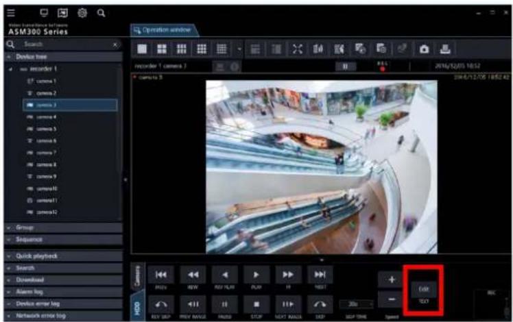
→ Text information of the recorded images will be displayed.

Step 4
Edit the text information.
Note:
• The following alphanumeric characters, half em numbers and marks are available.
ABCDEFGHIJKLMNOPQRSTUVWXYZ
abcdefghijklmnopqrstuvwxyz0123456789!"
# \$ % & ' ( ) * + , - . / : ; <= > ? @ [ ¥ ] ^ _ ` { | } \~ (space)
Step 5
Click the [OK] button.
→ The text registration confirmation window will be displayed.
Step 6
Click the [OK] button.
The edited text will be registered, and the confirmation window and the "Edit text" window will close.
4.2. Use the SD log display/playback window
Important:
- Check if the model in use is compatible with each function.
4.2.1. Download recorded images
While displaying live images, download H.264 or H.265 video files (mp4 files) from the SD memory card in the registered camera onto the PC.
Note:
- When two or more alarms occurred in the same file, they will be displayed on different log lists, but the same file will be downloaded. Video data will be saved as files and each file size is approx. 20 MB or 2 MB. When data which exceeds the size of file (20 MB or 2 MB), two or more files will be downloaded for an item of the list.
- Regarding log display and download for video, the available functions differ according to the camera model or versions. Descriptions are categorised into some groups. Read the following after confirming the group number in the table below according to the model and the version of the camera in use. For all cameras except Groups 1 and Groups 2, all functions described in this chapter can be used.
| Model (camera) | Version | Group number |
| 7-series camera | 1.05 or later | Group 1 |
| New 5-series camera(Except WV-SPN531 and WV-SPN531A) | 1.85 or later | |
| WV-SC385, WV-SW395J/WV-SW395AJ, WV-SW355,WV-SW352, WV-SW155, WV-SW152, WV-SW316LJ,WV-SW316J, WV-SW314J, WV-SW314,WV-SW396J/WV-SW396AJ, WV-SW396/WV-SW396A,WV-SC386, WV-SC384, WV-SW175, WV-SW172,WV-ST165, WV-ST162, BB-SW175A, BB-SW172A,BB-ST165A, BB-ST162A, BB-SC384A | All Group 2 |
- When "20MB" is selected for "Image saving interval" with the cameras of Group2, the recorded data may not be downloaded successfully. In that case, select "2MB" for "Image saving interval".
- If a brake is included in the recording of the camera of Group 2, "NG" may be displayed during download. However, downloading will not be affected and continued as long as data exists.
- When the overwriting of SD memory card is started with the cameras of Group 2, "NG" may be displayed for some list during download. As long as data exists, download will be continued.
- If the 6-series camera of version 1.83 is used, the H.264 video files stored in the SD memory card that is inserted in the slot 2 cannot be downloaded. Use the 6-series camera of version 1.85 or later. Also, in this case, the version of this software needs to be 3.40 or later.
- Log display and download with the camera of Group 2 with FTP connection. When the SSL communication is used between the camera of Group 2 and the PC, the log display and the download function are unavailable.
Step 1
Click the [List/Play] button on the SD operation panel of the operation window.
Refer to "SD operation panel" for the SD operation panel.
→ The SD log display/playback window will open.
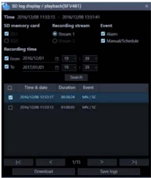
The details of the window are as follows.
■ Duration
Displays the recording time saved in the SD memory card.
Note:
- It is not available with the cameras of Group 2.
■ SD memory card
Selects the SD memory card for which log display to be enabled.
SD1: Displays logs saved in the SD memory card inserted in Slot 1.
SD2: Displays logs saved in the SD memory card inserted in Slot 2.
Note:
- It is not available with the cameras of Group 1 and 2.
• It is not available with a camera that is not equipped with two slots.
■ Recording stream
Selects the recording stream for which log display is to be enabled.
Stream 1: Displays logs saved in "Recording stream 1".
Stream 2: Displays logs saved in "Recording stream 2".
Note:
- It is not available with the cameras of Group 2.
- It is not available with a camera that does not support "Recording stream 2".
- If "Stream 2" is selected when "Recording stream 2" on the camera side is off, regardless of the presence or absence of recorded data, the error message "The device may be disconnected or no SD is inserted or SD is invalid." will be displayed. If the recorded data of "Recording stream 2" exists, click the [OK] button to close the error message and execute the search.
■ Event
Selects a type of logs to be displayed in the log list.
Alarm: Displays the log of alarm occurrence.
Manual/Schedule: Displays the log of manual saving and schedule saving.
■ Recording time
Set a period to specify logs to be displayed in the log list.
From: Set the start point for the log display.
To: Set the end point for the log display.
Note:
- When the checkbox "From" is unchecked, the logs will be displayed from the top. When the checkbox "To" is unchecked, the logs will be displayed to the end.
■ [Search] button
When this button is clicked, log search will start with the filters set by [Event] and [Recording time].
Search result will be displayed in the log list.
■ [I<] button
Click this button to display the log listed at the top.
■ [<] button
Click this button to display the previous page of the log list.
■ [>] button
Click this button to display the next page of the log list.
■ [>l] button
Click this button to display the log listed at the bottom.
■ Time & date
Indicates the time and date on which the logs were filed.
■ Duration
Displays the period of time in which data has been saved in the SD memory card.
Note:
• It is not available with the cameras of Group 1 and 2.
■ Event
Indicates the cause of the alarm occurrence.
When logs are obtained using HTTP function
MN/SC: Manual/Schedule
TRM: Terminal alarm
TRM1: Terminal alarm 1
TRM2: Terminal alarm 2
TRM3: Terminal alarm 3
VMD: VMD alarm
COM: Command alarm
AUD: Audio detection alarm
SCD: AVMD alarm (Scene change)
INT: iVMD alarm (Intruder)
LOI: iVMD alarm (Loitering)
DIR: iVMD alarm (Direction)
OBJ: iVMD alarm (Removal and left behind)
CLD: iVMD alarm (Cross line)
FTP: FTP error recording
NWLST: Network disconnection
When logs are obtained using FTP function
Terminal: Alarm by alarm input to Terminal 1
Terminal2: Alarm by alarm input to Terminal 2
Terminal3: Alarm by alarm input to Terminal 3
VMD: Alarm by VMD alarm
Command: Alarm by command alarm
Note:
• The supported events vary depending on the camera in use. • Refer to the operating instructions of the camera in use for further information.
■ [Download] button
The folder selection window will be displayed.
■ [Save logs] button
Saves the log list onto the PC.
Step 2
Select the list to download from the log list. Multiple selection of the list is available.
Step 3
Click the [Download] button.
→ The window for a folder designation will be displayed.

The details are as follows.
■ Destination folder
Specify a folder as the destination of downloaded files.
■ [Make New Folder(N)] button
Create a new folder in the folder currently selected.
■ [OK] button
The folder browse window will close and the download will start.
■ [Cancel] button
The window for a folder destination will close and the download will be canceled.
Note:
- The overwrite warning window will be displayed when a file of the same name already exists in the folder. If you do not wish to overwrite the existing file, cancel download and select another folder.
- It is impossible to click the [Download] button when no list is selected.
- When a removable HDD formatted on the 32-bit OS is connected to a PC whose OS is the 64-bit edition, it may fail to designate the removable HDD as a saving destination.
Step 4
Click the [OK] button after specifying a folder.
→ Download will start and the "Download" window will be displayed. Refer to "Use the download window" for the "Download" window.
Downloaded files will be stored in the specified folder.
Step 5
When the download is completed, click the [Quit] button.
The download window will close.
Note:
- When trying to exit this software or log out of the software during download, the download will be automatically cancelled.
4.2.1.1. About the downloaded files
It is possible to play video data saved on the PC using such an application as Windows Media® Player.
However, we are not liable for performance relating to these applications.
For information on playing back H.265 video data, refer to the following Panasonic website below.
https://security.panasonic.com/support/info/
Playback of images recorded on the SD 4.2.2. memory card
It is possible to play H.264 or H.265 video file saved on the SD memory card on the camera using the operation window.
Note:
- Files saved in JPEG format cannot be played.
- Image files recorded with a compression method different from the compression method set with the camera cannot be played.
- Only a single user can perform playback. When playback is being performed by another user, playback is unavailable.
- Playback will not end at the end point of the file. Playback of the next file will automatically start.
- When many images are saved on the SD memory card, it may take time to display images on the operation window.
- Only files saved on the camera that is registered as an independent camera can be played.
- When using this product in a country utilizing Summer Time (Daylight Saving Time), select "Auto" for the "Summer time (daylight saving)" setting of the camera in use. In this case, make sure that the "Start time & date" and "End time & date" settings are correctly set. When "Auto" is not selected for "Summer time (daylight saving)" or the "Start time & date" and "End time & date" settings are not correctly set, playback time may become incorrect or a black screen may be displayed.
- The playback is not available if the recorded time with the pre-event recording crosses the summer time switching zone. • The audio cannot be played if the audio is simultaneously recorded with the video.
Step 1
Display live images.
→ Refer to "Monitor images from the selected camera" for the live image display.
Step 2
Display the SD log display/playback window from the SD operation panel.
→ Refer to "Download recorded images" for descriptions about the window.

Step 3
Click an item to be played in the log list.
→ Images displayed on the operation window will be switched to playback of recorded images. The [Status] icon in the information display area will turn to [SD playback] from [Live].

Note:
- When the checkbox is checked, playback will not start.
- Playback will start from the time displayed in the list.
- When "ON" is selected for [Smooth display (buffering)] under [System] - [Drawing and audio setup], high-speed playback is unavailable.
Step 4
To stop playback, click the [STOP] button.
→ Live images will be displayed in the image display area where playback images are being displayed. The [Status] icon displayed in the information display area will change from [SD playback] to [Live].

Use the live window 4.3. How to launch the live window 4.3.1.
The live window will be launched when the [Live window] icon on the title bar of the ASM300 main page is clicked or when [Live window] is selected from the menu.
Refer to "Title bar" and "Menu" for further information about the title bar and the menu of the ASM300 main page.
Important:
- Images from data-encrypted cameras cannot be displayed on the live window. For details on "Data encryption", read the operation manual of the camera.
- When the Video Insight Server's checkbox "Enable Security" is marked ([Administrations] - [Servers] - [Server Setup] - [Advanced] - [Server Options]), images from Video Insight Server cannot be displayed.

Note:
- When a license of WV-ASE202 is added, up to 4 live windows can be displayed.
- When displaying images on more than one live window (it is necessary to add the license for the WV-ASE202), the display order will be Live window (1) → Live window (2) → Live window (3) → Live window (4). If the live window display is canceled on the way, display of images will start from a live window with the smallest number among the live monitors on which images were not displayed by the cancellation next time.
- When displaying images on more than one live window (it is necessary to add the license for the WV-ASE202) or when the maximum number of areas for the live window is set to 25 screens or more, it may take some time until the live windows are displayed.
- When displaying images on more than one live window (it is necessary to add the license for the WV-ASE202) by using two video cards, run on Windows 7 and turn off the Aero feature. When running on an operating system of Windows 8 or later, this function is not guaranteed since the Aero feature cannot be turned off.
4.3.2 Live window description
The following are descriptions about each item displayed on the live window. It is possible to open a new window by operating tabs of the live window. Refer to "Tab and Window" for further information.

■ Function panel
The function panel is provided on the left of the operation window. When the desired function bar on the function panel is clicked, the respective function panel will be displayed. Refer to "Function panel of the live window" for further information.
■ Group information display area
Status of the sequence and the group title will be displayed.
Refer to "Group information display area" for further information.
■ Camera information display area
Status of recording, alarm occurrence and the camera title will be displayed.
Refer to "Camera information display area" for further information.
■ Live image display area
Live images by the group display or the sequence display will be displayed.
It is also possible to automatically display live images from the camera in which an alarm occurred.
Refer to "Alarm action" for further information about the settings.
4.3.2.1. Function panel of the live window
Operate the live window using the function panel on the left side of the live window.
Each panel can be opened/closed by clicking the bar of the panel.
However, it is impossible to simultaneously open two panels or more.

Note:
• Refer to the following about the descriptions of how to operate each function panel.
Name search "Search for group name/sequence name"
The group panel can be operated in a similar manner as the operation window.
Refer to "Display images from the cameras registered as a group (group display)" for further information.
The sequence panel can be operated in a similar manner as the operation window.
Refer to "Switch groups automatically and display images from each group sequentially (sequence)" for further information.
- When "ON" is for "Display the panel open/close button", the panel open/close button will be
displayed next to the function panel. When the [Δ] icon on the panel open/close button is clicked, the function panel can be displayed or hidden. Refer to "Display/hide the function panel" for further information.
Refer to the " GUI display setup" for information about "Display the panel open/close button".
4.3.2.1.1. Display/hide the function panel
On the live window, displaying/hiding of the menu panel can be switched by operating the panel open/close button or the menu. When the menu panel is hidden by operating the menu, the panel open/close button will also be hidden. Displaying/hiding of the menu panel can be operated by clicking the icon [Δ] on the panel open/close button.
Refer to "Menu" for further information about the menu.
■ Display the function panel

■ Without the function panel

Note:
- It is also possible to switch between display/hide the function panel by selecting [Function panel] from the right-click menu displayed by right-clicking on the live image display area.
4.3.2.2. Group information display area
Note:
- When the setting is configured to automatically display live images from the camera in which an alarm occurred, the group information display area will not be displayed while displaying live images from this camera.
SEQ group 1-1
■ [SEQ]
Indicates that the sequence display is being performed currently. SEQ will be displayed when the sequence operation is in progress and SEQ will be displayed when the sequence operation is being paused.
This indication will not be displayed when the group display is being performed.
■ Group name
The group title will be displayed.
4.3.2.3. Camera information display area
camera1
Jun/21/2011 04:19:19 PM
■ REC indicator/Alarm mark
These indicators will light when the images currently being displayed are being recorded.
When the setting is configured to automatically display live images from the camera in which an alarm occurred, the REC indicator will turn to the alarm indicator.
■ Camera name
Indicates the camera name.
■ Descriptions of the time & date/alarm
Time & date will be displayed. When this software is configured to display live images directly from the camera in which an alarm occurred at an alarm occurrence, descriptions of the alarm will be displayed instead of time & date. The time & date will be followed by an asterisk "*" when the daylight saving time is applied.
4.3.2.4. Pop-up menu
When right-clicking on this area, the pop-up menu will be displayed.
There are two types of the pop-up menus as follows.
During the group display or the sequence display
During the live image display at an alarm occurrence
| Group | ▶ |
| Sequence | ▶ |
| Pause sequence | |
| Display camera/group title | ▶ |
| Function panel | |
| Frame display with face | |
| Display AVMD information | ▶ |
| Full screen | |
| No image display on all areas |
| Function panel |
| Frame display with face |
| Alarm mode reset |
| Full screen |
■ Group
Select a group to be displayed in the live image display area from the submenu.
■ Sequence
Select a sequence to be displayed in the live image display area from the submenu.
■ Pause sequence/Resume sequence
Select to pause or resume the sequence display. "Pause sequence" will be displayed when the sequence display is in progress and "Resume sequence" will be displayed when the sequence display is being paused. This cannot be selected when the group display is being performed.
■ Display camera/group title
It is possible to switch between display/hide the group information display area and the camera information display area from the submenu.
■ Function panel
It is possible to switch between display/hide the function panel of the live window.
■ Frame display with face
It is possible to display/hide the border frame displayed around a face when detected.
Important:
• It is possible to select after the license for the WV-ASE231 is added. - This function will be valid only when a camera having the face search function is connected to ASM300 and the face search function is ON.
■ Display AVMD information
It is possible to display/hide frame borders and traces using the submenu.
Note:
• The AVMD information function will become available after the license for the WV-ASE231 is added. • The AVMD information function is supported by some models only. • AVMD information will be displayed only when displaying images on 1-screen. - When displaying images (MPEG-4) via ND300 or ND200, AVMD information will not be displayed. • i-VMD information of the camera will also be displayed - When displaying images via ND300, ND200, NV200, or NV300, i-VMD information will not be displayed.
- To display i-VMD information while displaying images via ND400, it is necessary to update the firmware of ND400 to V3.40 or later.
- When "Frame display (only after determination)" is selected, AVMD frame will be displayed after AVMD alarm is confirmed.
■ Alarm mode reset
The alarm mode will be canceled and it returns to the state before the alarm occurrence.
■ Full screen
The live image display area, the group information display area and the camera information display area will be displayed on a full screen.
■ No image display on all areas
Clear the images displayed on all the areas.
Display images from cameras registered as a 4.3.3 group using the function panel/Display images while switching groups automatically
The group display/sequence display from the function panel can be operated in a similar manner as the operation window.
Refer to the following descriptions for further information.
Group panel "Display images from the cameras registered as a group (group display)"
Sequence panel "Switch groups automatically and display images from each group sequentially (sequence)"
Note:
- When a sequence operation is started on the live window, the screen will not automatically change to the full screen. To display images on the full screen, select "Full screen" from the pop-up menu.
4.3.4. Search for group name/sequence name
It is possible to search for a registered group/sequence name.
Step 1
Enter a desired group/sequence name in the search field at the upper part of the function panel of the live window.

Note:
• The maximum number of characters that can be entered is 16. - Search will be executed with partial match of a name, and en space, em space, upper-case and lower-case will not be distinguished. - The live window will become inoperable during a screen on which the search is being executed is being displayed.
→ When the search is ended, the panel including items that match the name entered in the search field will turn to orange color.

Step 2
When the panel colored in orange is clicked and opened, the search result will be displayed.
Note:
• The search result shows only items that partially matched with the name entered in the search field. • The other items will not be displayed.
Step 3
When the name entered in the search field is deleted, it returns to the previous state before the search.

Note:
- It is possible to delete the name entered in the search field by clicking the [×] button on the right side of the search field.
Use the map window 4.4. How to launch the map window 4.4.1.
The map window will be launched when the [Map window] icon on the title bar of the ASM300 main page is clicked or when [Map window] is selected from the menu.
Refer to "Title bar" and "Menu" for further information about the title bar and the menu of the ASM300 main page.

The following are descriptions about each item displayed on the map window. It is possible to open a new window by operating tabs of the map window. Refer to "Tab and Window" for further information.
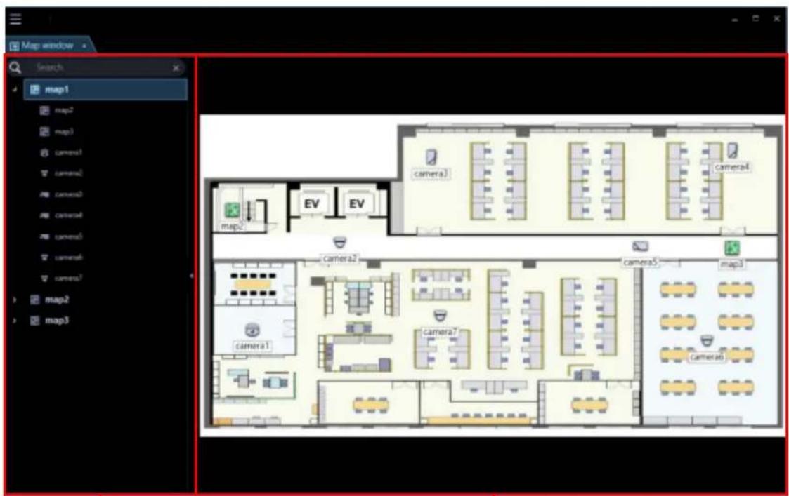
The registered map names and camera names will be displayed in list form.
Refer to "Function panel of the map window" for further information.
■ Map display area
The selected map will be displayed. The camera icons and the map icons will be displayed on the map.
■ Icon title
Display titles of icons on the map. It is possible to determine whether to display or hide the icon title on the setup window. Refer to "GUI display setup" for further information.
4.4.2.1. Function panel of the map window
It is possible to switch maps and search for a camera icon on a map using the function panel on the left side of the map window.

• Refer to the following descriptions of how to operate the function panel.
Name search "Search for a map/camera name"
Refer to "Map icon ➕ Switch maps" for further information.
Refer to "Camera icon Search for a camera icon on a map" for further information.
4.4.2.1.1. Display/hide the function panel
It is possible to switch between display/hide the function panel by operating the panel open/close button or menu on the map window. When the function panel is set to be hidden, the panel open/close button will also not be displayed. When the [Δ] icon on the panel open/close button is clicked, the function panel can be displayed or hidden.
Refer to "Menu" for further information about the menu.
■ Display the function panel

■ Without the function panel
Note:
- It is also possible to switch between display/hide the function panel by selecting [Function panel] from the right-click menu displayed by right-clicking on the map display area.
4.4.2.2. Pop-up menu
When right-clicking on a camera icon displayed on a map, a pop-up menu will be displayed.
Note:
- If the AUX terminal number is changed to a desired name, the renamed one will be displayed in AUX1, AUX2, and AUX3.
For details on changing the terminal name, refer to "Set the AUX terminal name".

■ AUX1
It is possible to switch the state of the device connected to the AUX1 terminal between open/close from the submenu.
Note:
- When using Video Insight Server, AUX1 is not available.
■ AUX2
It is possible to switch the state of the device connected to the AUX2 terminal between open/close from the submenu.
Note:
- When using Video Insight Server, AUX2 is not available.
■ AUX3
It is possible to switch the state of the device connected to the AUX3 terminal between open/close from the submenu.
Note:
- When using Video Insight Server, AUX3 is not available.
■ Return to regular icons.
The icon can be restored to the regular icon.
It is enabled when the camera connection is disconnected.
When right-clicking on the image display area, the following items will be displayed on a pop-up menu.
If you right-click on the map display area or map icon, the following items are displayed in the pop-up menu.
■ Function panel
It is possible to switch between display/hide the function panel of the map window.
4.4.2.3. Icons on the map
The following are the descriptions of the icons displayed on the map.
Note:
• A preview image will be displayed by placing the mouse cursor on a camera icon on a map.

- When the camera icon on the map is clicked, live images from the selected camera will be displayed in the selected area on the operation window.
- When right-clicking on the camera icon displayed on the map, the pop-up menu will be displayed. It is possible to switch the state of the device connected to the AUX terminal between open/close from the submenu.
- When a map icon displayed on the map is clicked, the respective map will be displayed on the map window. • It is also possible to set to display titles of each icon under icons on a map.
Refer to " GUI display setup" for further information.
Important:
• A preview image can be displayed only in the following cases.
● In case of receiving live images from a camera that is not registered in a recorder - In case of directly receiving live images from a camera registered in a recorder, not through the recorder ● In case of acquiring live images via ND400 or NX-series
- When using a recorder other than ND400 and NX-series and selecting [Recorder] for [Live image source], the preview display is unavailable.
- If the camera does not support this software (“Compatible cameras”), such as the ONVIF connection camera, the preview image will not be displayed.
- In the case of Fisheye camera, the preview image becomes fish-eye display irrespective of the setting.
| Icon | Description |
 | Indicates dome camera 1Indicates also a state in connection with this camera. |
 | Indicates dome camera 2Indicates also a state in connection with this camera. |
 | Indicates dome camera 3Indicates also a state in connection with this camera. |
 | Indicates dome camera 4Indicates also a state in connection with this camera. |
 | Indicates dome camera 5Indicates also a state in connection with this camera. |
 | Indicates dome camera 6Indicates also a state in connection with this camera. |
 | Indicates dome camera 7Indicates also a state in connection with this camera. |
 | Indicates dome camera 8Indicates also a state in connection with this camera. |
 | Indicates dome camera 9Indicates also a state in connection with this camera. |
 | Indicates dome camera 10Indicates also a state in connection with this camera. |
 | Indicates dome camera 11Indicates also a state in connection with this camera. |
| [4GKS] | Indicates dome camera 12There are 2 types of fixed type and PTZ type.Indicates also a state in connection with this camera. |
 | Indicates dome camera 13Indicates also a state in connection with this camera. |
 | Indicates fixed camera 1Indicates also a state in connection with this camera. |
 | Indicates fixed camera 2Indicates also a state in connection with this camera. |
 | Indicates fixed camera 3Indicates also a state in connection with this camera. |
 | Indicates fixed camera 4Indicates also a state in connection with this camera. |
 | Indicates fisheye camera 1Indicates also a state in connection with this camera. |
 | Indicates fisheye camera 2Indicates also a state in connection with this camera. |
 | Indicates fisheye camera 3Indicates also a state in connection with this camera or an microphone. |
 | Indicates an aero PTZ cameraIndicates also a state in connection with this camera. |
 | Indicates a state in disconnection with a camera or an microphone.When right-clicking on the camera icon, the pop-up menu will be displayed. When "Return to regular icons." is selected, the camera icon will indicate that the camera is online. |
 | |
 | Indicates also that a camera or a microphone is in an alarm state. The icon will blink for 10 seconds after receiving an alarm. When the icon is clicked, the icon will indicate that the camera is online. |
 | Indicates a map. |
4.4.3. Display live images from the map window
Click a desired camera icon on a map.

→ Live images from the selected camera will be displayed on the image display area of the operation
window.
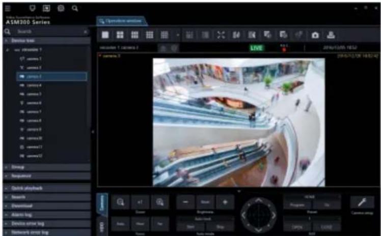
Switch maps 4.4.4.
When a map name of the function panel is clicked, the clicked map will be displayed in the map display area.

- It is also possible to switch maps by clicking a map icon on the map.
4.4.5. Search for a camera icon on a map
When a camera icon on the function panel is clicked, a map in which the corresponding camera icon is registered will be displayed in the map display area and a circle frame surrounding the camera icon will appear and will blink for 3 seconds.
![graph TD A["Map window"] --> B["Search"] B --> C["map1"] C --> D["map2"] D --> E["map3"] E --> F["map2"] F --> G["map3"] H["Map window"] --> I["Search"] I --> J["map1"] J --> K["map2"] K --> L["map3"] L --> M["map2"] M --> N["map3"] style A fill:#f9f,stroke:#333 style H fill:#ccf,stroke:#333 style I…](/content/2026/06/1353903/images/452194af188bbecf7c9224894d5ed7eff7d7fe1a8fab8865c314c8f4af6981dd.jpg)
4.4.6. Search for a map/camera name
It is possible to search for a registered map/camera name.
Step 1
Enter a desired map/camera name in the search field at the upper part of the function panel.

• The maximum number of characters that can be entered is 16. Search will be executed with partial match of a name, and en space, em space, upper-case and lower-case will not be distinguished. The map window will become inoperable during a screen on which the search is being executed is being displayed.
→ When the search is ended, items that partially matched with the name entered in the search field will be displayed.

• The search result shows only items that partially matched with the name entered in the search field. The other items will not be displayed.
Step 2
When the name entered in the search field is deleted, it returns to the previous state before the search.
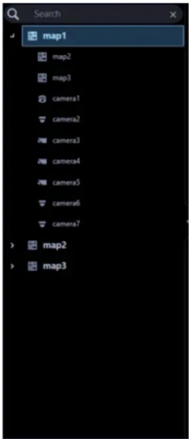
- It is possible to delete the name entered in the search field by clicking the [×] button on the right side of the search field.
Use the search window 4.5.
On the search window, it is possible to search for a desired image from recorded images in a recorder.
It is possible to open a new window by operating tabs of the search window.
Refer to "Tab and Window" for further information.
The search window consists of the following 3 tabs.
■ REC event search
Searches for recording events by units of recorders, groups and maps.
Refer to "REC event search" for further information.
■ VMD search
Searches for the time and date when motion was detected in images from recorded images.
Refer to "VMD search" for further information.
■ Thumbnail search
Searches for a thumbnail by camera units from recorded images in a recorder.
Refer to "Thumbnail search" for further information.
REC event search 4.5.1.
4.5.1.1. REC event search tab description
This tab searches images from the recorded images of the recorder by specifying search criteria such as a REC event.

■ Search by
Select the search target from the following.
- Recorder
Searches for images by recorder units. When "Recorder" is selected, the device tree will be displayed in the search target list box. Select a recorder and a camera to be searched from the device tree.
- Group
Searches by units of groups. When "Group" is selected, the group list will be displayed in the search target list box. Select a group to be searched from the group list.
- Map
Searches by units of maps. When "Map" is selected, the map list will be displayed in the search target list box. Select a map to be searched from the map list.
■ REC event
Select a recording event to be searched.
- Manual: Select to search for images recorded by manual recording.
- Schedule: Select to search for images recorded by the schedule recording. • Emergency: Select to search for images recorded by the emergency recording.
- Site alarm: Select to search for images recorded upon the site alarm occurrence. • Terminal alarm: Select to search for images recorded upon the terminal alarm occurrence. • Command alarm: Select to search for images recorded upon the command alarm occurrence. • VMD: Select to search for images recorded by the video motion detection. • Video loss: Select to search for images recorded upon the video signal loss.
- SD memory rec.: Select to search for SD memory data.
Note:
- "SD memory rec." is unavailable to select together with other recording event types. To search for the SD memory data, select "SD memory" alone.
■ i-VMD
Select the i-VMD type to be searched.
• Terminal alarm: Select to search for images recorded upon the terminal alarm occurrence. - Removal and left behind: Select to search for images recorded upon the detection relating to removal and left behind. • Direction: Select to search for images recorded upon the detection relating to direction. - Scene change: Select to search for images recorded upon the detection relating to scene change. • Motion: Select to search for images recorded upon the detection relating to motion. - Loitering: Select to search for images recorded upon the detection relating to loitering.
Note:
- i-VMD search is available only when HD600 is selected for the search target.
■ Text
It is possible to search for recorded images only with or without text information. Select "Added" or "None". When "--" is selected, images will be searched regardless of with or without text information.
Stream
Select a stream.
- Stream 1: Selects stream 1.
- Stream 2: Selects stream 2.
- ALL: Selects both stream 1 and stream 2.
Note:
• Selection of stream is available only when NX-series is selected as a search target.
■ Start Time
Select the start time of period to be searched from "2005/1/1" - "2034/12/31".
Select a number for hour from "0" - "23". Select a number for minute (1 minute step).
■ End Time
Select the end time of period to be searched from "2005/1/1" - "2034/12/31".
Select a number for hour from "0" - "23". Select a number for minute (1 minute step).
■ [OK] button
Starts the search.
■ [Cancel] button
Cancels the selected search conditions and closes the search window. Then, returns to the operation window.
■ Number of search results
Search result number will be displayed.
■ Search result list
Search result will be displayed in list form. When a search result is clicked, playback will start on 1-screen on the operation window.
When playback of the selected result starts, the descriptions of the selected result will be displayed in the search panel of the operation window.
Note:
- No image will be displayed when search result number is "0".
4.5.1.2. Search for a recording event (REC event search)
Search for a recording event as follows.
It is possible to search for the following recording events by designating the search target; recorders, groups and maps.
- Manual
- Schedule
- Emergency
- Site alarm
- Terminal alarm
- Command alarm • VMD
- Video loss
- SD memory rec.
i-VMD
- Terminal alarm • Removal and left behind
- Direction
- Scene change
- Motion
- Loitering
Note:
- It is impossible to execute the SD memory data search together with other recording event simultaneously.
- Up to 1000 search results will be displayed. When more than 1000 search results are found, the latest 1000 search results will be displayed in the search result list. When searching in multiple recorders, number of search results per a recorder will be (1000/number of recorders).
- i-VMD search is available only when HD600 is selected for the search target. Search for images by designating time & date, camera channel and recording event type as the search conditions. (REC event search)
4.5.1.2.1. Set a search condition
Search for images by designating time & date, camera channel and recording event type. (REC event search)
Step 1
Click the [Search] icon on the title bar or select [Search] from the menu.
→ The "Search" window will be displayed.
Step 2
Set up the search conditions.
- Select [Recorder] of [Search by]. → The registered recorders will be displayed in the tree view. The subsequent operations are executed on the following window.

- Select the recorders and the cameras to be searched.
- Select a recording event to be searched from [REC event].
- Designate the time range to be searched by setting the start time and the end time.
- Determine whether to search for recorded images with text information or without it.
- Select [Group] of [Search by].
→ The registered groups will be displayed in list form. The subsequent operations are executed on the following window.

- Select a group to be searched from the search target list.
- Select a recording event to be searched from [REC event].
- Designate the time range to be searched by setting the start time and the end time.
- Determine whether to search for recorded images with text information or without it.
- Select [Map] of [Search by].
→ The registered maps will be displayed in list form. The subsequent operations are executed on the following window.

- Select a map to be searched from the search target list.
- Select a recording event to be searched from [REC event].
- Designate the time range to be searched by setting the start time and the end time.
- Determine whether to search for recorded images with text information or without it.
Step 3
Click the [OK] button.
→ Search will start and the window with the progress bar will be displayed.

Note:
- When playback is being performed on the operation window, playback will stop and live images will be displayed.
- Search results will continue to be added to the search result list while the window with the progress bar is displayed. If the [Cancel] button is clicked while the window with the progress bar is displayed, search results added to the search result list up to that point will not be deleted.
- It is impossible to operate other windows while the screen on which the search is being executed is displayed.
→ When the search is complete, the "Search result" window will be displayed.

Note:
- If [HDD stand-by control mode] of the recorder is valid, set the search period to less than 120 minutes. If the search period is set to 120 minutes or more, the total number of items will be "1" and the search results will not be displayed correctly. Also, if the search period is less than 120 minutes, only the total number may not be displayed correctly.
Refer to the operating instructions of the recorder in use for further information about the "HDD stand-by control mode".
Step 4
Click the [Close] button.
→ The confirmation window will close.
Note:
- The search results will be displayed in the following order: time & date, recorder name, camera name, recording event name, and text.
- When a search result is clicked, the search window will close and playback on 1-screen will start. At the same time, the search panel of the operation window will open and content of the selected result list will be displayed. Refer to "Play recorded images using the "Search" panel" for the search panel.
- Once a playback is performed from the search results, the search result will not be deleted until a new search is performed or until the user logged out or exit the software.
4.5.1.3. Play from the search results
Play recorded images from the search 4.5.1.3.1.
result list
It is possible to play images displayed in the search result list.
Step 1
Click the desired result displayed in the search result list.

→ Live images of the selected group will be displayed on the registered multi-screen.

Note:
- Playback of the search result is also available by clicking a desired result displayed in the "Search" panel. Refer to "Play recorded images using the "Search" panel" for how to use the search panel.
Play recorded images using the "Search" 4.5.1.
panel
The description of the search results displayed in the search result list will be displayed in the "Search" panel in list form.
Select a desired image from the search result lit and start playback.
Step 1
Click the "Search" bar on the function panel.
→ The "Search" panel will be displayed.

The details of the window are as follows.
■ [Search]/[Re-search] button
Click this button to display the "Search" window. If no search has been executed before, the [Search] button will be displayed. If contents are displayed in the search result list, the [Re-search] button will be displayed.
■ Search result list
The search results will be displayed with the following information: time & date, recorder title, camera title, recording event type, with or without text.
Step 2
Click a desired image to play in the search result list.
→ Live images of the selected group will be displayed on the registered multi-screen.
Note:
- When clicking a result displayed in the search result list, recorded images of the respective result will be displayed on a 1-screen. When playback is started, all images displayed in the image display areas will be cleared.
- When right-clicking on the search result list, the pop-up menu will be displayed. Playback of recorded images of the specific group is available by selecting the desired group from the group list displayed on the submenu of the right-click pop-up menu. However, if "SD memory backup" is selected as a search target in "Recording event", the group playback will become unavailable.
- When playing back images from the search list with Video insight Server, the recorded image may not be displayed right after the recording is started because the data has not been stored.
VMD search 4.5.2.
4.5.2.1. VMD search tab description
Searches for time and date when a motion was detected in images from recorded images.
This function is available only with ND400, HD600, NV200, NV300 or NX-series.
If ND400, HD600, NV200, NV300 or NX-series is registered, the [VMD search] tab will be displayed.

■ Search by
Select a recorder and a camera to be searched.
■ Start Time
Select the start time of period to be searched from "2005/1/1" - "2034/12/31".
Select a number for hour from "0" - "23". Select a number for minute (1 minute step).
■ End Time
Select the end time of period to be searched from "2005/1/1" - "2034/12/31".
Select a number for hour from "0" - "23". Select a number for minute (1 minute step).
■ [Image display] button
Import the image of the start time & date from the recorder.
■ Image area
Display the images obtained from the recorder.
The areas to be searched for are specified by dragging in the image area. Up to 4 areas can be specified.
■ [All areas] button
Select all the areas to be searched for.
■ [Delete] button
Delete the same colored areas.
■ Sensitivity
Select the sensitivity for each area from the following.
- Off: Does not detect the motion in this area.
- Low: Low sensitivity • Mid: Standard sensitivity • High: High sensitivity
Note:
• Selection of sensitivity is available only when HD600 is selected for the search target.
■ Mask duration
Select the duration to mask detection in the same area from the following.
- When HD600 is in use: 1s/ 1min/ 60min/ 24h
- When any of NV200, NV300 and NX-series is in use: 1s/ 5s/ 10s/ 30s/ 1min/ 5min/ 10min
Note:
- Selection of mask duration is available only when HD600, NV200, NV300 or NX-series is selected as the search target.
■ [OK] button
Starts the search.
■ [Cancel] button
Cancels the designated search conditions and closes the search window. Then, returns to the operation window.
■ Number of search results
Search result number will be displayed.
■ Search result list
Search result will be displayed in list form. When a search result is clicked, playback will start on 1-screen on the operation window.
When playback of the selected result starts, the descriptions of the selected result will be displayed in the search panel of the operation window.
Note:
• No image will be displayed when search result number is "0".
4.5.2.2. Search for time and date when a motion is detected in images (VMD search)
Searches for time and date when a motion was detected in images from recorded images.
Note:
• This function is available only with ND400, HD600, NV200, NV300 or NX-series. - If ND400, HD600, NV200, NV250, NV300 or NX-series is registered, the [VMD search] tab will be displayed. - When using V-series camera, this function is unavailable. - Up to 200 search results will be displayed.
4.5.2.2.1. Determine the search conditions
The time & date, camera channel, and motion detection area are specified to perform searching. (VMD search)
Step 1
Click the [Search] icon on the title bar or select [Search] from the menu.
Step 2
Click the [VMD search] tab on the search window.
→ The "VMD search" window will be displayed.
Step 3
Set up the search conditions.

- Select a recorder and a camera to be searched for from the search target list. Only 1 recorder or 1 camera can be selected.
- Designate the time range to be searched by setting the start time and the end time.
- Click the [Image display] button. The image of the camera to be searched for is displayed.

Note:
- The image on the operation window will be cleared.
- Specify areas by dragging on the image area. Up to 4 areas can be specified.
Note:
- When the recorder to be searched is the HD600 and the image of the camera is specified for the detection area from the top to bottom, search will be unavailable (The area whose search will be available is the same as that configured on the HD600.).
Step 4
Click the [OK] button.
Search will start and the window with the progress bar will be displayed.

When the search is complete, the "Search result" window will be displayed.

Refer to "Play recorded images from the search result list" for how to play from the search result list.
4.5.2.3. Play from the search results
Play recorded images from the search 4.5.2.3.1.
result list
It is possible to play images displayed in the search result list.
Step 1
Click the desired result displayed in the search result list.

→ Live images of the selected group will be displayed on the registered multi-screen.

Note:
- Playback of the search result is also available by clicking a desired result displayed in the "Search" panel. Refer to "Play recorded images using the "Search" panel" for how to use the search panel.
Play recorded images using the "Search" 4.5.2.
panel
The description of the search results displayed in the search result list will be displayed in the "Search" panel in list form.
Select a desired image from the search result lit and start playback.
Step 1
Click the "Search" bar on the function panel.
→ The "Search" panel will be displayed.

The details of the window are as follows.
■ [Search]/[Re-search] button
Click this button to display the "Search" window. If no search is executed before, the [Search] button will be
displayed. If contents are displayed in the search result list, the [Re-search] button will be displayed.
■ Search result list
The search results will be displayed with the following information: time & date, recorder title, camera title, recording event type, and whether text is present.
Step 2
Click a desired image to play in the search result list.
→ Live images of the selected group will be displayed on the registered multi-screen.
Note:
- When clicking a result displayed in the search result list, recorded images of the respective result will be displayed on a 1-screen. When playback is started, all images displayed in the image display areas will be cleared.
- When right-clicking on the search result list, the pop-up menu will be displayed. Playback of recorded images of the specific group is available by selecting the desired group from the group list displayed on the submenu of the right-click pop-up menu.
- When playing back images from the search list with Video Insight Server, the recorded image may not be displayed right after the recording is started because the data has not been stored yet.
Thumbnail search 4.5.3.
4.5.3.1. Thumbnail search tab description
Searches for a thumbnail by units of cameras from recorded images in a recorder.
This function is available only with NX-series. If NX-series is registered, the thumbnail search tab will be displayed.
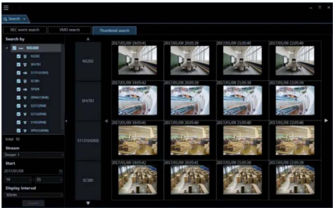
Function panel 4.5.3.1.1.
It is possible to designate search conditions on the function panel on the left side of the thumbnail search tab and start a search.
Note:
- The panel open/close button will be displayed at the side of the menu panel. Displaying/hiding of the menu panel can be operated by clicking the icon [Δ] on the panel open/close button.

■ Search by
Select a recorder to be searched.
■ Total
Number of the selected cameras as the search target.
Stream
Select a stream. Select either of "Stream 1" and "Stream 2".
■ Start Time
Select the start date of period to be searched from "2005/1/1" - "2034/12/31".
Select a number for hour from "0" - "23". Select a number for minute (1 minute step).
■ Display interval
Select a thumbnail display interval of from the following.
■ [Search] button
Starts the search.
Thumbnail display area 4.5.3.1.2.

| CAM1 | 2017/01/09 13:05:41 | 2017/01/09 20:05:39 | 2017/01/09 21:05:40 | 2017/01/09 22:05:40 |
| CAM2 | 2017/01/09 13:05:42 | 2017/01/09 26:05:39 | 2017/01/09 21:05:39 | 2017/01/09 22:05:39 |
| CAM3 | 2017/01/09 13:05:41 | 2017/01/09 20:05:40 | 2017/01/09 21:05:40 | 2017/01/09 22:05:40 |
| CAM4 | 2017/01/09 13:05:42 | 2017/01/09 20:05:41 | 2017/01/09 21:05:39 | 2017/01/09 22:05:39 |
■ Camera name
The camera name selected as the search target will be displayed.
■ Thumbnail
A mapped thumbnail image of the search result will be displayed on the plane made by two axes of "time" and "camera".
When a desired thumbnail image is clicked, it will be in the selected state and be surrounded by a frame in orange. When a thumbnail is double-clicked, playback will start on 1-screen on the operation window.
Note:
- If no recording data is found at "Start time", thumbnails will be displayed for the period of time set by "Display interval" starting from "Start time". • No image will be displayed when search result number is "0".
■ Change time axis button (✗() ▶
When ◀ is clicked, thumbnails of the past will be displayed.
When ▶ is clicked, thumbnails of the future will be displayed.
■ Thumbnail display camera switch buttons (▲) (▼)
When ▲ or ▼ is clicked, a camera for which a thumbnail is to be displayed will be changed.
4.5.3.2. Search for a thumbnail (Thumbnail search)
4.5.3.2.1. Set a search condition
Search by specifying time & date, camera channel, stream type and thumbnail display interval. (Thumbnail search)
Step 1
Click the [Search] icon on the title bar or select [Search] from the menu.
→ The "Search" window will be displayed.
Step 2
Click the [Thumbnail search] tab of the search window.
→ The thumbnail search window will be displayed.
Step 3
Designate search conditions.

- Select cameras to be searched from the search target list. Up to 128 cameras can be selected at a time.
- Select a stream.
- Select a start time.
- Select a display interval.
Step 4
Click the [Search] button.
→ Search will start and the window with the progress bar will be displayed.

Note:
- The image on the operation window will be cleared.
- While the search result window is being displayed, thumbnail images will be kept on being displayed as the search results. Even when the [Cancel] button is clicked to cancel the search, thumbnails will be displayed as the search results before the [Cancel] button was clicked.
- It is impossible to operate other windows during a screen on which the search is being executing is being displayed.
→ When the search is completed, thumbnails will be displayed as the search results.
16 thumbnails will be displayed in order from left to right and from top to bottom starting from the top left as the start time.

4 thumbnails per camera will be displayed in order from left as the start time to right.

Note:
• The display time of thumbnails may be at a few seconds before or after the specified time. - If there is no recorded image at the specified date and time, the thumbnail image different from the input date and time is displayed.
4.5.3.3. Play from the thumbnail search results
Thumbnail images will be displayed as the search results.
Step 1
Double-click a desired thumbnail to play.

→ Live images of the selected group will be displayed on the registered multi-screen.
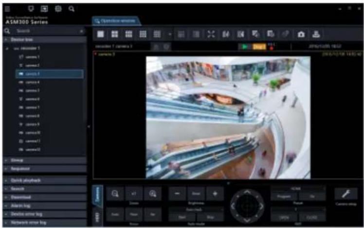
Note:
- When a thumbnail in the search results is double-clicked, playback of images recorded at that time will start on 1-screen. When playback is started, all images displayed in the image display areas will be cleared.
4.6. Use the visibility enhancement function Enhance images 4.6.1.
4.6.1.1. Precautions
Important:
- To use the visibility enhancement function, it is necessary to purchase the extension software WV-ASE205 separately. • To use the visibility enhancement function, your use requirements shall be met with the recommended operating environment for the extension software WV-ASE205.
Recommended operating environment
| Item | Details |
| CPU | Core i7 7700 or better |
| GPU (Graphic card) | GeForce GTX660 or more or NVIDIA Quadro P1000 *1 *2GeForce GTX770 or more or NVIDIA Quadro P1000 (for image capture size of 2048x1536 or more)*1 *2(The version GeForce 332.21 or later is recommended for the driver software.) |
*1: When using the visibility enhancement function, prepare and use a power supply unit compatible with the graphics card in use. *2: When using the visibility enhancement function, do not use two or more graphics cards.
Note:
- The visibility enhancement function is not supported by Video Insight Server and HD300. However, live images can be enhanced only when the "camera" is selected for the "live image source" on the "Camera setup" of Video Insight Server.
- When using the image enhancement function, displaying images on multi-screen of the operation window is not available.
- When using the image enhancement function, the sequence display of the operation window is not available.
- When the operation window is switched to image display on multi-screen while using the image enhancement function, the image enhancement function will be invalidated.
- When the operation window is switched to a sequence display while using the visibility enhancement function, the visibility enhancement function will be invalidated.
- When any of the following operations are performed while using the image enhancement function, the image enhancement function will be invalidated.
REV PLAY FF REW PREV IMAGE PAUSE
- When any of the following operations are performed while using the image enhancement function, snowfall or rainfall may temporarily be displayed.
- When the connected device or the PC is under heavy load, the image refresh rate or the switching speed of the visibility enhancement function may become slower depending on the network environment.
- The recommended frame rate is 5 - 30 fps. When capturing fast-moving objects or noisy objects, set the frame rate to 10 fps or more.
• The bit rate shall be set to a higher value according to the resolution.
- When displaying images whose contrast is very low, images may sometimes not be enhanced.
• The higher the resolution is set, the sharper details of images will be.
- Depending on the image quality or the frame rate of input images, an expected effect may not be obtained.
- Set the image quality and the frame rate of input images as high as possible.
- When input images are greatly changed by a PTZ operation, an expected effect may not be obtained.
- Images to be displayed may sometimes be delayed when other function of ASM300 such as the live window is used.
• An after-image or a noise may be emphasized under a low illumination environment.
- When images are displayed with "5 Cropping" or "1 Cropping", the "Visibility Enhancement" function is unavailable.
• To use the "Visibility Enhancement" function, set the monitor resolution to lower than FULL HD.
- When using a camera with the image capture size of more than 4000 x 3000 while setting the correction mode to "Snowfall and Rainfall", set the frame rate of the camera to "5 fps".
- When setting the image capture size of more than 3840 x 2160 using a camera, set "4K" to "PC diagnosis (4K camera)" of the setup window. Refer to "Drawing and audio setup" for further information.
4.6.1.2. Remove snowfall and rainfall
Snowfall or rainfall will be removed from images.
Step 1
Click the [Visibility Enhancement] icon on the operation window.
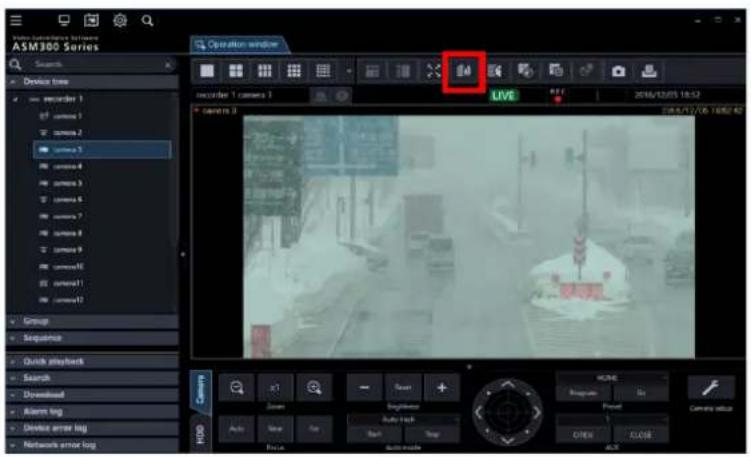
Step 2
Select "Snowfall and Rainfall" in the "Correction mode" section on the "Visibility Enhancement" window.
Step 3
Adjust the correction level using the slider bar in the "Correction level adjustment" section on the "Visibility Enhancement" window.

Step 4
The settings will be saved by clicking the [Close] button on the visibility enhancement window.
4.6.1.3. Remove fog or mist
Fog or mist will be removed from images.
Step 1
Click the [Visibility Enhancement] icon on the operation window.

Step 2
Select "Fog and Mist" in the "Correction mode" section on the visibility enhancement window.
Step 3
Adjust the correction level using the slider bar in the "Correction level adjustment" section on the "Visibility Enhancement" window.

Step 4
The settings will be saved by clicking the [Close] button on the visibility enhancement window.
4.6.1.4. Improve backlight images
It is possible to improve backlight images.
Step 1
Click the [Visibility Enhancement] icon on the operation window.

Step 2
Select "Backlight" in the "Correction mode" section on the visibility enhancement window.
Step 3
Adjust the correction level using the slider bar in the "Correction level adjustment" section on the "Visibility Enhancement" window.

Step 4
The settings will be saved by clicking the [Close] button on the visibility enhancement window.
4.6.1.5. Make a dark area brighter
It is possible to make a dark area brighter.
Step 1
Click the [Visibility Enhancement] icon on the operation window.

Step 2
Select "Dark area" in the "Correction mode" section on the visibility enhancement window.
Step 3
Adjust the correction level using the slider bar in the "Correction level adjustment" section on the "Visibility Enhancement" window.

Step 4
The settings will be saved by clicking the [Close] button on the visibility enhancement window.
4.6.1.6. Enhance images using user settings
Images can be enhanced by configuring user settings.
Note:
• Level 4 for "Snowfall and Rainfall" is set as the default for each user setting. • The default names of the user settings are [User setting 1] – [User setting 4].
Step 1
Click the [Visibility Enhancement] icon on the operation window.

Step 2
Select any of "User setting 1" - "User setting 4" in the "Correction mode" section on the visibility enhancement window.
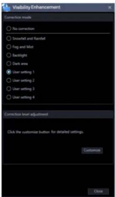
Customize the user settings 4.6.2. 4.6.2.1. Adjust the parameters
All the parameters for the visibility enhancement function can be adjusted.
Step 1
Click the [Visibility Enhancement] icon on the operation window.

Step 2
Select any of "User setting 1" - "User setting 4" in the "Correction mode" section on the visibility enhancement window.
Step 3
Click the [Customize] button in the "Parameter adjustment" section on the visibility enhancement window.

Step 4
Select a setting to be used as the basis of adjustment on the "Template" section on the visibility enhancement setting window.
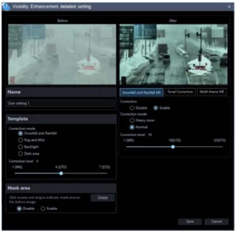
Step 5
Adjust the parameters on each tab page of "Snowfall and Rainfall NR", "Spatial Tonal Correction" and "Multi-frame NR" of the visibility enhancement setting window. Descriptions about each parameter are provided on "Parameter list table".
Step 6
The settings will be saved by clicking the [Save] button on the visibility enhancement detailed setting window.
Parameter list table
| Snowfall and Rainfall Noise Reduction | Correction | "Snowfall and Rainfall NR" can be turned on and off by selecting "Enable" or "Disable".It is not possible to enable only "Snowfall and Rainfall NR" and "Multi-frame NR". |
| Correction mode | Available setting value: Normal, Heavy snowThe following correction modes can be selected for "Snowfall and Rainfall NR".Normal: Correction level can be adjusted by setting "Correction level" below.Heavy snow: The maximum correction level will be applied. | |
| Correction level | Available setting value: 1 - 32Correction level for "Snowfall and Rainfall NR" can be adjusted. When a larger value is set, size of snow flakes that can be deleted will become larger. When a larger value is set, an after-image of a moving object will be reduced. | |
| Spatial Tonal Correction | CorrectionCorrection mode | "Spatial Tonal Correction" can be turned on and off by selecting "Enable" or "Disable".Available setting value: Contrast, Dark area, Bright area, Backlight The following correction modes can be selected for "Spatial Tonal Correction".Contrast: Improve visibility of low contrast images.Dark area: Improve visibility of very dark areas.Bright area: Improve contrast of very bright areas.Backlight: Improve visibility of images where extremely bright and dark areas are mixed. |
| Correction level | Available setting value: 0 - 255Correction level for "Spatial Tonal Correction" can be adjusted. | |
| Brightness | Available setting value: 0 - 255Brightness can be adjusted. | |
| Color tone strength | Available setting value: 0 - 255Colors can be enhanced. | |
| Correction radius | Available setting value: 0 - 255When a larger value is set, correction will be applied to a whole image with well balance.When a smaller value is set, a local contrast can be emphasized. When a smaller value is set, processing load will be increased and it may cause delay of images. | |
| Multi-frame NR | Correction | "Multi-frame NR" can be turned on and off by selecting "Enable" or "Disable".It is not possible to enable only "Snowfall and Rainfall NR" and "Multi-frame NR". |
| Correction level | Available setting value: 0 - 36Correction level for "Spatial Tonal Correction" can be adjusted. | |
| Motion type | Available setting value: Fixed, Pan, Pan/Tilt, Pan/Tilt/Zoom, Free Select a motion type of frame to align frame position. When many frame motion type are used, processing load will become heavier and it may cause video delay.Fixed: Select this when frames do not have any motion (Such as a fixed camera)Pan: Select this when frames move horizontally onlyPan/Tilt: Select this when frames move horizontally and verticallyPan/Tilt/Zoom: Select this when frames move horizontally and vertically, and also zoom in and out (Such as a PTZ camera)Free: Select this when frames move horizontally and vertically, zoom in and out, and also rotate (Such as a wearable camera) | |
| Accuracy | Available setting value: 1 - 16Accuracy of position alignment between frames can be adjusted. | |
| Range | Available setting value: 1 - 16Range of position alignment between frames can be adjusted. | |
| Detection mode | Available setting value: Normal, FastDetects a moving object. | |
| When “Fast” is selected, only the pixel level detection will be performed. | ||
| Detection level | Available setting value: 0 - 15 Moving object detection level can be adjusted. |
4.6.2.2. Edit the name
Name of the selected user setting can be edited. Enter up to 16 characters for a name.
Step 1
Click the [Visibility Enhancement] icon on the operation window.

Step 2
Select any of "User setting 1" - "User setting 4" in the "Correction mode" section on the visibility enhancement window.
Step 3
Click the [Customize] button in the "Parameter adjustment" section on the visibility enhancement window.
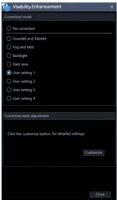
Step 4
Enter a name for the setting in the [Name] field of the visibility enhancement detailed setting window.

Step 5
The settings will be saved by clicking the [Save] button on the visibility enhancement detailed setting window.
4.6.2.3. Set a mask area
Areas to which the image enhancement function is not to be applied can be set.
Step 1
Click the [Visibility Enhancement] icon on the operation window.

Step 2
Select any of "User setting 1" - "User setting 4" in the "Correction mode" section on the visibility
enhancement window.
Step 3
Click the [Customize] button in the "Parameter adjustment" section on the visibility enhancement window.

Step 4
Check the "Enable" checkbox of [Mask area] on the visibility enhancement detailed setting window.

Step 5
Specify a mask area by dragging the mouse in [Image before correction] on the visibility enhancement detailed setting window.
Step 6
The settings will be saved by clicking the [Save] button on the visibility enhancement detailed setting window.
4.6.2.4. Delete a mask area
Delete a mask area.
Step 1
Click the [Visibility Enhancement] icon on the operation window.

Step 2
Select any of "User setting 1" - "User setting 4" in the "Correction mode" section on the visibility enhancement window.
Step 3
Click the [Customize] button in the "Parameter adjustment" section on the visibility enhancement window.

Step 4
Click the [Delete] button in [Mask area] on the visibility enhancement detailed setting window.

Step 5
The settings will be saved by clicking the [Save] button on the visibility enhancement detailed setting window.
In the following cases 4.6.3. 4.6.3.1. Need to remove snowfall and rainfall more
Enable "Snowfall and Rainfall NR".
Select "Heavy snow" for "Correction mode" of "Snowfall and Rainfall NR".
When "Normal" is selected for "Correction mode" of "Snowfall and Rainfall NR", adjust the correction level higher.
Note:
- Appearance of after-image of a moving object or disappearance of moving object itself may sometimes occur as a result of removing snowfall and rainfall.
4.6.3.2. Need to remove fog and mist more
Enable "Spatial Tonal Correction".
Select "Contrast" for "Correction mode" of "Spatial Tonal Correction".
Set a smaller value for "Correction radius" of "Spatial Tonal Correction".
Note:
• Outline in images may sometimes be excessively emphasized as a result of removing fog and mist.
4.6.3.3. Need to make a dark area more brighter
Enable "Spatial Tonal Correction".
Select "Dark area" for "Correction mode" of "Spatial Tonal Correction".
Set a larger value for "Brightness" of "Spatial Tonal Correction".
4.6.3.4. Need to improve backlight images more better
Enable "Spatial Tonal Correction".
Select "Backlight" for "Correction mode" of "Spatial Tonal Correction".
4.6.3.5. Images are too noisy
Enable "Multi-frame NR".
Set a larger value for "Correction level" of "Multi-frame NR".
Note:
- Appearance of trajectories of moving objects or disappearance of moving object may sometimes occur as a result of setting a larger value for "Correction mode" of "Multi-frame NR".
4.6.3.6. Appearance of trajectories of moving objects or disappearance of moving object occurred
Disable "Multi-frame NR".
Set a smaller value for "Correction level" of "Multi-frame NR".
Select "Normal" for "Detection mode" of "Multi-frame NR".
Disable "Snowfall and Rainfall NR".
Select "Normal" for "Correction mode" of "Snowfall and Rainfall NR".
Set a smaller value for "Correction level" of "Snowfall and Rainfall NR".
4.6.3.7. Need to hide the text "This image is enhanced." displayed on images during "Visibility Enhancement"
Set "Visibility Enhancement Text Display" to "OFF" on the setup window.
Refer to "Text display setting" for further information.
Use the face search monitor 4.7.
Note:
- The logo on the face search monitor is displayed as follows according to the version and operation mode of the face search server.
< In the case of WV-ASF900 or WV-ASF950 version less than 2.00>

Face Search
< In the case of WV-ASF950 version 2.00 or later (registered face detection mode)>

Face Search
< In the case of WV-ASF950 version 2.00 or later (registered face/unregistered face detection mode)>

Face Search
Search face 4.7.1. 4.7.1.1. Search by time and date
Perform the face search by designating time and date.
Important:
- To use the face search function, it is necessary to purchase WV-ASF950 or WV-ASF900, and the extension software WV-ASE231.
Step 1
Click the [Face Search] tab on the face search monitor.

Step 2
Select the start time and the end time of [Time & date].

■ Start Time
Select the start time of period to be searched.
Select a number for hour from "0" - "23". Select a number for minute (1 minute step).
■ End Time
Select the end time of period to be searched.
Select a number for hour from "0" - "23". Select a number for minute (1 minute step).
Step 3
Click the [Search] button.
The search result window will be displayed.
4.7.1.2. Search by face
Perform the face search by designating face features.
Step 1
Click the [Face Search] tab on the face search monitor.
Step 2
Designate a face image.

■ Person icon
The face image setting can be configured as follows.
- Display the "List of registered faces" window by left-clicking the person icon, and then select a face image.
- Drag and drop the face image of the search result onto the person icon. • Right-click on the person icon, and then select from the following menu.
[Select from list of registered faces.]
[Select face image from the snapshot]
- Right-click on a face image on a paused playback image displayed on the ASM300 operation window, and then select [Set to Face Search 1] or [Set to Face Search 2] from the displayed menu. (* This operation is available only when the [Face Search] tab page is being displayed.)
■ Similarity
The search can be filtered by specifying the similarity. Only the images above the specified similarity level will be displayed as search result.
■ [Clear] button
Clear both the images of filter 1 and filter 2. It will also restore the default setting of "Similarity".
Designate the person (face image) to be searched
- Select from the registered images
Right-click on a person icon of [Faces] on the [Face Search] tab page and select [Select from the registered face image list] from the menu.
→ The "List of registered faces" window will be displayed.

■ Search result
To register a face image from the search result face thumbnail, right-click on the face thumbnail and select [This face set as filter.] from the menu.
To register a face image from the search result face thumbnail in filter 1, right-click on the face thumbnail and select [Set to Face Search 1] from the menu. To register in filter 2, right-click on the face thumbnail and select [Set to Face Search 2] from the menu.
■ [OK] button
Closes the "List of registered faces" window and applies to the search condition.
■ [Cancel] button
Closes the "List of registered faces" window and cancels to apply to the search condition.
- Select face image from the snapshot
Right-click on a person icon in [Faces] on the [Face Search] tab page and select [Select face image from the snapshot] from the right-click menu.
→ The "Select face image from the snapshot" window will be displayed.
■ [Ref.] button
Select an image file to be read in the "Select face image from the snapshot" window.
Note:
• The available file formats are JPEG, PNG, and BMP.
■ Snapshot display area
When an image file is read, the face detection process will be carried out and a white border frame will be displayed around each face.
The detected faces will be displayed above the image.

■ Image display area for setting the search condition
The selected face image will be displayed.
■ [OK] button
Close the registration window and apply the search condition.
■ [Cancel] button
Close the registration window and cancel the search condition.
- Pause the playback at the point when the target person is displayed in playback images. Then, right-click on the face image and select [Set to Face Search 1] or [Set to Face Search 2].
→ The "Face thumbnail list" will be displayed in the playback window.
Note:
• The searching image can be changed from the "Face thumbnail list".
Designate the camera to be searched
Check the checkbox of the camera to be searched.
< In the case of WV-ASF900 or WV-ASF950 (version less than 2.00) or WV-ASF950 [version 2.00 or later (registered face detection mode)]>

Note:
- The cameras obtained by "Face search - server registration" of the setup window will be displayed in the tree.
- When the checkbox of "Parent node (server)" is checked, the checkboxes of all the child nodes will be checked automatically.
- When the checkbox of "Parent node (server)" is unchecked, the checkboxes of all the child nodes will be unchecked automatically.

Note:
- The area set in the "Area management" window and the cameras registered in the selected server among the cameras registered in the area will be displayed in the tree. Refer to "Set area" about the area.
Step 3
Click the [Search] button.
→ The search result window will be displayed.
4.7.1.3. Play recorded image in search result

Click the [Search] button.
→ The search result window will be displayed.
There are two ways of how to display the search result; [Timeline] and [List].
Click the [Timeline] tab.
A mapped thumbnail image of the search result will be displayed on the plane made by two axes of "timeline" and "location".

Click the [List] tab. The search result will be displayed with thumbnail images in list form.
When "Face image" is set for the search condition, the search result will be listed in order of the highest score of similarity.
When "Face image" is not set for the search condition, the search result will be listed in order of the detection time.

Note:
• In the timeline view, 2560 faces are searched from the end time, and up to 512 faces are displayed. - In the list view, it is searched in a range of 24 hours from the end time, and up to 512 items are displayed.
■ Number of search, page information
Total number of search result and the page number of the currently displayed page will be displayed as shown below.
The buttons to turn pages will be displayed as shown below.

■ Attribute information
In the search result, the face image and the additional information of "Similarity" and "Time & date" (when image is captured) will be displayed. In addition, in case of a listed location, "Year/Month/Day" (when image is captured) will also be displayed.


■ Face image display size
The size of the image to be displayed can be changed by operating the bar.
The image size can be selected from 5 different sizes.
1 (Small): 72×72, 2: 90×90, 3: 120×120, 4: 140×140, 5 (Large): 180×180

This function is available only when displayed by "Timeline" or "List" of the face search result window, or when displayed
by "Location/List" of "Search by time and date".
■ Original size display
The face image can be displayed in its original size.
If the cursor is moved over a thumbnail image, 📁 will be displayed at the bottom right of the image.

When is clicked, the face image will be displayed in its original size in the another window.
Note:
- The original size image can also be displayed by right-clicking on the thumbnail to show the pop-up menu. Select [Display the original size of this face image]. • More than two images cannot be displayed.
- Click the [×] button to close the window.
Operation from thumbnail image of search result
The following operations are available using the thumbnail image of a search result.
- People search
Right-click on the thumbnail image and select [People search] from the menu.
→ The people search for the selected face image will be automatically started.
- Apply to search condition of the people search
Right-click on a thumbnail image and select [Set to People Search 1] or [Set to People Search 2] from the right-click menu.
→ The selected image will be displayed in the section of "Faces" of the "People Search" window.
- Apply to filter of the face search
Right-click on a thumbnail image and select [Set to Face Search 1] or [Set to Face Search 2] from the right-click menu.
→ The selected image will be displayed in the section of "Faces" of the search display window.
- Register as a person (face) of whom alarm is to be notified
Right-click on the thumbnail image and select "Register this face" from the right-click menu.
→ The "Select and register face image from file" window will be displayed.
(To "Register from a face thumbnail image")
• Additional registration of a person (face) to the existing registrations of alarm notification
Right-click on the thumbnail image and select "Additionally register this face image" from the right-click menu.
→ The list window of registered face images will be displayed.
(To "Register 2 or more face images of a same person")
- Right-click on a recorded image on the playback thumbnail image and select "Play the video" from the right-click menu.
→ Image recorded at the alarm occurrence time will be played. Recorded images will be played on the operation window.
Note:
- When the operation window is used with a multi-screen, it will be switched to 1-screen.
- It is also possible to play recorded images by double-clicking a thumbnail image.
- The [People search], [Set to People Search 1], and [Set to People Search 2] menus will be displayed only if the people search server exists.
4.7.1.4. Output face search result in HTML
The face search result can be output in a HTML file.
Step 1
Click the [List] tab of the [Face search] page, and then click the

Output the list
button.
→ The window for specifying the destination folder of the saving file will be displayed.
Step 2
Specify the destination folder of the saving file, name the file, and then click the [OK] button.
→ The window to show the output progress will be displayed.

A dated folder will be automatically created in the specified folder, and a file will be saved there with the specified name.
Step 3
When the file saving process is complete, a confirmation window for displaying the result will be displayed.
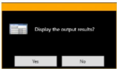
Click [OK] button to open the output HTML file in the browser.
Note:
If an HTML tag is entered in "Remarks" on the face image registration screen, the layout of the output HTML file may be affected.
Check the alarm notification 4.7.2.
Alarm notifications for face search include face matching alarm notifications and unregistered face detection alarm notifications.
The face matching alarm notification message will be displayed in a pop-up window (alarm notification window) on the operation window in the following cases.
- When using WV-ASF900 or WV-ASF950 (version less than 2.00) and a person registered with the face search monitor is detected by the camera.
- When the operation mode of the face search server is "registered face detection" mode, and a person registered on the face search monitor is detected by the camera.
- When the operation mode of the face search server is "registered face/unregistered face detection" mode, and a person registered on the face search monitor is detected by the camera as a registered face.
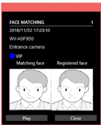
■ Face matching alarm notification message
Alarm information, number of alarms, time and date of the alarm occurrence, device name in which an alarm has occurred (face search server name), the title of the camera, category color, category name, matching face, and registered face will be displayed.
Also, the content of "Remarks" set during face registration will be displayed in the tooltip when the mouse cursor is placed on the alarm notification message window.
The unregistered face detection alarm notification message will be displayed in a pop-up window (alarm notification window) on the operation window in the following cases.
- When the operation mode of the face search server is "registered face/unregistered face detection" mode and a person not registered on the face search monitor is detected by the camera.
- When the operation mode of the face search server is "registered face/unregistered face detection" mode and a person registered on the face search monitor is detected by the camera as an unregistered face.

■ Unregistered face detection alarm notification message
Alarm information, number of alarms, date and time of the alarm occurrence, device name in which an alarm has occurred (face search server name), area name and the title of the camera, matching face, and registered face will be displayed.
Note:
- The unregistered face detection alarm notification message window will be popped up when using WV-ASF950 version 2.00 or later.
- The following image will be displayed as a registered face image on the unregistered face detection alarm notification message window.

4.7.2.1. Display the alarm notification window
When a face search alarm notification or an unregistered face detection alarm is received, the contents of the alarm will be displayed in list form.
Step 1
Click the [Alarm] tab on the face search monitor.

The details are as follows.
■ Display the face image to be registered
In the face image registration, the representative face image for which "Constant display" is set will be displayed per category.
(It is available when "ON" is selected for "List of high profile persons" of the setup window.) If alarm is constantly displayed, it is enclosed with a red frame. The red frame will be canceled if it is clicked.
Category
Category name that is set when registering face image
Note:
- When received an unregistered face detection alarm notification, it will be blank.
■ Time & date
Time and date when the face search alarm or the unregistered face detection alarm is occurred
■ Camera
Name of the camera that notified of the face search alarm or the unregistered face detection alarm
■ Matching face
Indicates the thumbnail image verified by the face search server
■ Registered face
Indicates the matched face image by the face search in the registered face thumbnail images
Note:
- The following image will be displayed as a registered face image on the unregistered face detection alarm notification message window.

Name
Indicates name of registered person
Note:
- When received an unregistered face detection alarm notification, it will be blank.
■ Remarks
Additional information relating to the registered person (face), etc.
Note:
- When received an unregistered face detection alarm notification, it will be blank.
■ Similarity
Similarity between the face registered in advance and the detected face
Note:
- When a window (such as the alarm search window, face search window, or the age and gender window) other than the [Alarm] tab page on the face search window is displayed, the displayed window will not automatically be switched to the [Alarm] tab page even if an alarm notification is received.
- The list is displayed in two rows. The upper row of the list displays the three most recent alarms. The lower row of the list can be scrolled.
- When displaying the [Alarm] page for the first time, or when re-opening the "Face search monitor" window, the latest 100 alarms will be displayed on the screen.
- When another user deletes an alarm (Delete occurred alarms from the list), the corresponding alarm will be deleted from the list.
- When an unregistered face detection alarm notification is received, it will be blank.
4.7.2.2. Play images recorded by the alarm recording
Play images recorded at the time of the alarm occurrence from the recorder.
Step 1
Right-click on a line of the person to be checked in the video from the notification list on the [Alarm] tab page, and then select [Play the video] from the right-click menu.
→ Recorded images will be played on the operation window.
Note:
- When the operation window is used with a multi-screen, it will be switched to 1-screen. • It is also possible to play recorded images by double-clicking a list item.
4.7.2.3. Delete occurred alarms from the list
Unnecessary alarms can be deleted from the alarm list.
Step 1
Click the button on the line of the image you want to delete in the list of the [Alarm] tab.
→ The deletion confirmation window will be displayed.
< In the case of WV-ASF900 or WV-ASF950 (version less than 2.00) or WV-ASF950 [version 2.00 or later (registered face detection mode)]>
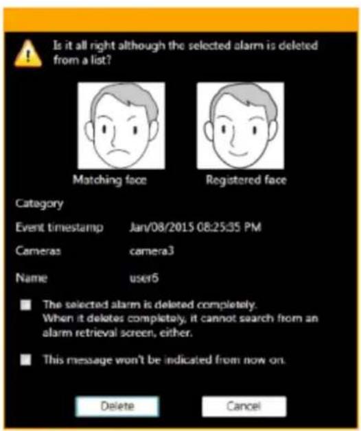
Matching face, registered face, category, date & time of alarm occurrence, the title of the camera, and name will be displayed.

Matching face, registered face, date & time of alarm occurrence, area name, and the title of the camera will be displayed.
Note:
- When an unregistered face detection alarm notification is received, the following image will be displayed as a registered face image.

Step 2
Click the [Delete] button.
→ The selected alarm will be deleted and the [Alarm] page will be restored.
Note:
- Normally, the deletion only deletes data from the list. The face search server still keeps the data. If the check mark of "The selected alarm is deleted completely." is removed, data will completely be deleted from the face search server and it will become impossible to search from the alarm search window after this. - When the checkbox of "This message won't be indicated from now on." is checked, the deletion confirmation window will not be displayed for subsequent deletions and alarms will immediately be deleted from the list. To display the delete confirmation window again, set "ON" for "Face alarm deletion confirmation window" of the setup software.
Refer to "Configure the behavior setting of the face search" for further information.
- The ▲ button will not be displayed if the user is not authorized for deletion of alarms.
- When failed to connect with the face search server upon the startup of the face search monitor, the [Delete] button will not be displayed even after the connection with the face search server is established. To display the [Delete] button, restart the face search monitor.
Search the alarm notification 4.7.3.
4.7.3.1. Search by time and date
Perform the alarm notification search by designating time and date.
Step 1
Click the [Alarm search] tab on the face search window.

Step 2
Select the start time and the end time of [Time & date].

■ Start Time
Select the start time of period to be searched.
Select a number for hour from "0" - "23". Select a number for minute (1 minute step).
■ End Time
Select the end time of period to be searched.
Select a number for hour from "0" - "23". Select a number for minute (1 minute step).
Note:
- If the "Deleted alarm is included" checkbox is checked and searched, the deleted alarm images will also be included as search targets. However, completely deleted images will not be displayed. • For the deleted alarm images, 📄 will be displayed.

Step 3
Click the [Search] button.
→ The search result window will be displayed.
4.7.3.2. Search by person (face)
Perform the face search by designating face features.
Step 1
Click the [Alarm search] tab on the face search window.
Step 2
Designate a face image.

■ Person icon
The face image setting can be configured as follows.
- Display the "List of registered faces" window by left-clicking the person icon, and then select a face image. • Right-click on the person icon, and then select from the following menu.
[Select from list of registered faces.]
- Drag and drop the face image of the search result onto the person icon.
- Alarm search condition (In the case of WV-ASF950 version 2.00 or later (registered face/unregistered face detection mode))
Select the alarm to search for.
- Registered face detection: Search for the face matching alarm notifying that the person registered was detected by the camera.
- Unregistered face detection: Search for the unregistered face detection alarm notifying that the person unregistered was detected by the camera.
Default: Select both
Note:
- When the face image is set to the person icon while both are selected, the selection of unregistered face detection alarm will be cleared automatically.
- When face image is set to the person icon, registered face detection alarm is selected automatically. In this state, when deselecting the registered face detection alarm, the face image will be cleared automatically.
- When a face image is set for the person icon and an unregistered face detection alarm is selected, the face image will be cleared automatically.
■ [Clear] button
Clear the search condition.
Designate the person (face image) to be searched
- Select from the registered images
Right-click on a person icon of [Faces] on the [Alarm Search] tab page and select [Select from list of registered faces.] from the right-click menu.
→ The "List of registered faces" window will be displayed.

■ List item
Select a person to be searched from the "List of registered faces" displayed on the right side.
■ [OK] button
Closes the "List of registered faces" window and applies to the search condition.
■ [Cancel] button
Closes the "List of registered faces" window and cancels to apply to the search condition.
Designate the camera to be searched
Check the checkbox of the camera to be searched.
< In the case of WV-ASF900 or WV-ASF950 (version less than 2.00) or WV-ASF950 [version 2.00 or later (registered face detection mode)]>

Note:
- The cameras obtained by "Face search - server registration" of the setup window will be displayed in the tree.
- When the checkbox of "Parent node (server)" is checked, the checkboxes of all the child nodes will be checked automatically.
- When the checkbox of "Parent node (server)" is unchecked, the checkboxes of all the child nodes will be unchecked automatically.

Note:
- The area set in the "Area management" window and the cameras registered in the area (camera registered in the selected server) will be displayed in the tree. Refer to "Set area" about the area.
Step 3
Click the [Search] button.
→ The search result window will be displayed.
4.7.3.3. Play recorded image in search result
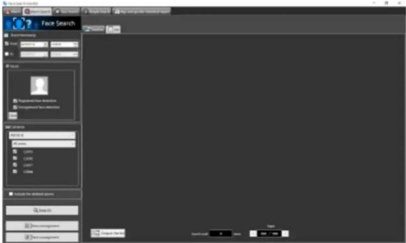
Click the [Search] button.
→ The search result window will be displayed.
There are two types of displaying the search result; [Timeline] and [List].
Click the [Timeline] tab.
A mapped thumbnail image of the search result will be displayed on the plane made by two axes of "timeline" and "location".

Click the [List] tab. Search result will be displayed in list form.

Note:
- When received an unregistered face detection alarm notification, the following image will be displayed as a registered face image.

■ Number of the search result, page information
Total number of search result and the page number of the currently displayed page will be displayed as shown below.
The buttons to turn pages will be displayed as shown below.

Operation from thumbnail image of search result
The following operations are available using the thumbnail image of a search result.
- Apply to face search filter Right-click on a thumbnail image and select [Set to Face Search 1] or [Set to Face Search 2] from the right-click menu.
→ The selected image will be displayed in the "Faces" section of the search display window.
- Register as a person (face) for alarm notification Right-click on the thumbnail image and select "Register this face" from the right-click menu.
→ The "Select and register face image from file" window will be displayed. (See "Register from a face thumbnail image")
- Additional registration of a person (face) to existing alarm notification registrations Right-click on the thumbnail image and select "Additionally register this face image" from the right-click menu.
→ The list window of registered face images will be displayed. (See "Register 2 or more face images of the same person")
- Apply to alarm search filter Right-click on a thumbnail image and select [Set to alarm search] from the right-click menu.
→ The selected image will be displayed in the "Faces" section of the alarm search display window.
- Playback of recorded images Right-click on a thumbnail image and select [Play from a recorded time & date] from the right-click
menu.
→ The image recorded at the alarm occurrence time will be played. Recorded images will be played in the operation window.
Note:
- When the operation window is used with a multi-screen, it will be switched to 1-screen. • It is also possible to play recorded images by double-clicking a thumbnail image.
4.7.3.4. Output alarm search result in HTML
The alarm search result can be output in an HTML file.
Step 1
Click the [List] tab of the [Alarm search] page, and then click the Output the list button. The window for specifying the destination folder of the saving file will be displayed.
Step 2
Specify the destination folder of the saving file, name the file, and then click the [OK] button. The window to show the output progress will be displayed.

A dated folder will be automatically created in the specified folder, and a file will be saved there with the specified name.
Step 3
When the file saving process is complete, a confirmation window for displaying the result will be displayed.

Click [OK] button to open the output HTML file in the browser.
Note:
- The Output the list button will not be displayed if the user is not authorized for output of a list of searched face alarms.
- When HTML tag is entered in "Remarks" on the face image registration screen, the layout of the output HTML file may be affected.

Set area 4.7.4.
It is possible to select an operation to notify an alarm when a registered person is detected by the camera and an operation to notify an alarm when an unregistered person is detected by the camera for each area. The cameras can be set in the area to detect a person.
Note:
- Area setting is possible when using WV-ASF950 version 2.00 or later (registered face/unregistered face detection mode). • The camera always belongs to one of the areas.
4.7.4.1. Add area
Step 1
Click the [Area management] button in one of the following tabs, [Alarm], [Alarm search] or [Face search].

→ The "Area management" window will be displayed.
Note:
- If a user without authorization of "Area setting in face alarm" is logged in, the [Area management] button will not be displayed. For information on the user rights, refer to "User level setup".

The details of the window are as follows.
■ Camera list
Display all cameras registered on the face search server.
By entering characters in the camera name search field, only the relevant camera will be displayed.
Note:
- Cameras in the camera list can be added by dragging and dropping anywhere in "Area tree". At this time, you can select multiple cameras.
■ Detection mode display
Display the detection mode for each area.

Indicate that registered face detection is set.

Indicate that unregistered face detection is set.
■ Area tree
Displays cameras registered in the area in a tree format.
By entering part of the area name or part of the camera name in the search field, the relevant area or relevant camera will be searched for.
Default: There is a default area, and all cameras are registered in the default area.
Note:
• The cameras can be moved between areas by dragging and dropping cameras in "Area tree". - The display order of areas can be changed by dragging and dropping areas in the area tree. The display order for the camera can be also changed as well.
■ [Add] button
Add a new area.
Note:
- Up to 100 areas can be registered.
■ [Edit] button
Edit the area name and the detection mode.
■ [Delete] button
Delete the created area.
■ [Save] button
Save the set content.
■ [Cancel] button
Cancel the edited contents and resets the contents to the state before editing.
■ Registered number of areas
Number of the registered areas will be displayed.
Step 2
Click the [Add] button.
→ The "Add/Edit area" window will be displayed.

■ Area name
Enter the area name within 20 characters. Symbols except full-width symbols can not be entered.
■ Detection mode
Select whether to detect registered faces in the area or unregistered faces in the area.
Refer to "Register a face for the alarm notification" for area selection at face registration.
- Registered face detection: Detects a person registered in the "Registered face detection" area and issues an alarm.
- Unregistered face detection: Detects a person not registered in the "Unregistered face detection" area and issues an alarm.
Initial state: Unregistered face detection
■ [OK] button
Complete the settings and close the window.
■ [Cancel] button
Cancel the edited contents and close the window.
Step 3
After setting the area information, click the [OK] button.
→ Area registration is completed and the window returns to the "Area management" window.
Step 4
Drag and drop the cameras in the camera list to the area in the area tree.
→ The camera will be added to the registered area.
Note:
- To move cameras at once, select multiple cameras by mouse operation and drag and drop them.
- When you add a camera to an area tree and drag and drop the same camera from the camera list to a different area, that camera will move automatically in the area tree.
Step 5
Click the [Save] button.
→The settings will be saved. If not registering, click the [Cancel] button.
Important:
- After clicking the [Save] button, restart this software on this PC and other PCs connected to face search servers to reflect the settings.
4.7.4.2. Edit area
Step 1
Click the [Area management] button in one of the following tabs, [Alarm], [Alarm search] or [Face search].

→ The "Area management" window will be displayed.
Note:
- If a user without authorization of "Area setting in face alarm" is logged in, the [Area management] button will not be displayed. For information on the user rights, refer to "User level setup".
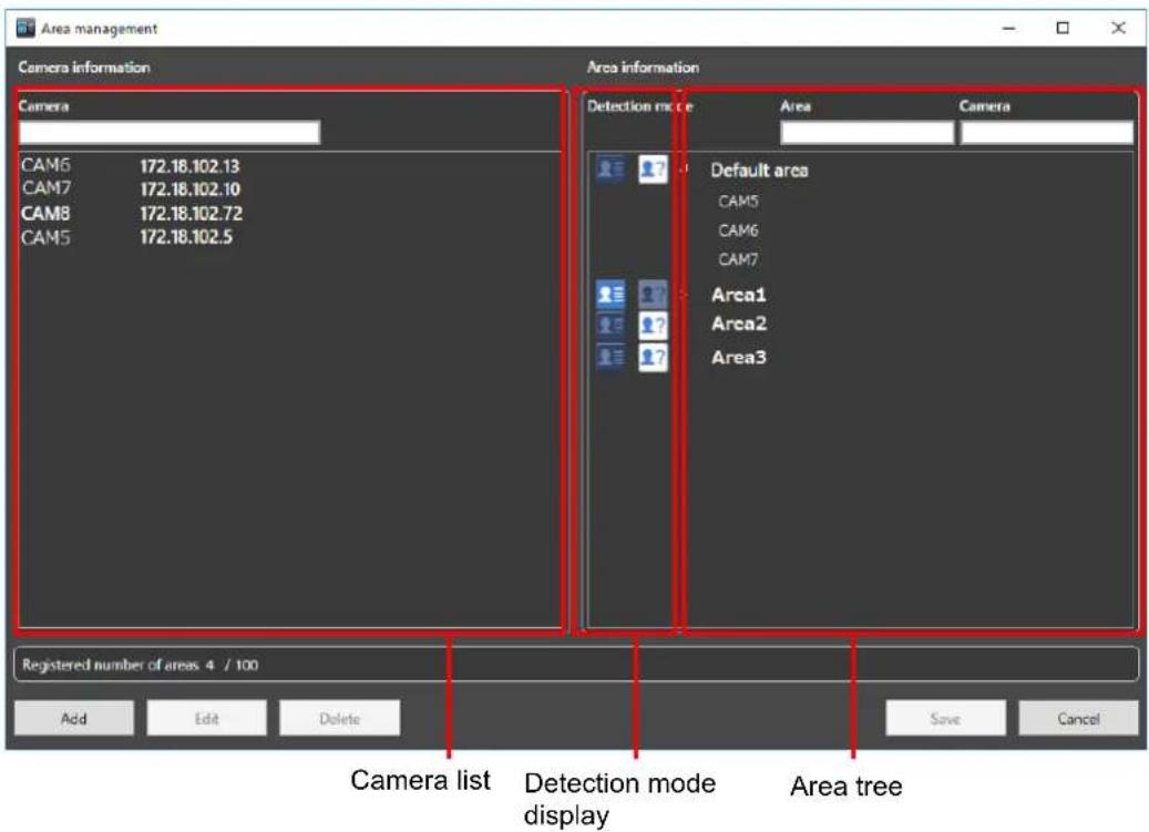
Step 2
After selecting the area to be edited, click the [Edit] button.
→ The "Add/Edit area" window will be displayed.

Step 3
Edit the area name. If you change the face detection type of the area, edit the detection mode.
Step 4
Click the [OK] button.
→ Area registration is completed and the window returns to the "Area management" window.
Step 5
Click the [Save] button.
→ The settings will be saved. If not registering, click the [Cancel] button.
Important:
• After clicking the [Save] button, restart this software on this PC and other PCs connected to face search servers to reflect the settings.
4.7.4.3. Delete area
Step 1
Click the [Area management] button in one of the following tabs, [Alarm], [Alarm search] or [Face search].

→ The "Area management" window will be displayed.
Note:
- If a user without authorization of "Area setting in face alarm" is logged in, the [Area management] button will not be displayed. For information on the user rights, refer to "User level setup".

Step 2
After selecting the area to be deleted, click the [Delete] button.
→ The deletion confirmation window is displayed.

Step 3
Click the [OK] button.
→ Area registration is completed and the window returns to the "Area management" window.
Note:
- When a camera is registered in the selected area, the area can not be deleted. After moving the camera to another area, delete the area.
- The default area can not be deleted.
Step 4
After deleting the area, click the [Save] button.
Important:
- After clicking the [Save] button, restart this software on this PC and other PCs connected to face search servers to reflect the settings.
4.7.5. Search for designated people 4.7.5.1. Search by face
Perform the face search by designating the face.
Important:
- To use the people search function, it is necessary to purchase WV-ASF900 and the extension software WV-ASE231. Also, the people search server needs to be connected.
Step 1
Click the [People Search] tab on the face search monitor.

Step 2
Designate a face image.

■ Person icon
The face image setting can be configured as follows.
- Display the "Select face image from snapshot" window by left-clicking the person icon, and then select a face image. For details, refer to "How to set up a face image from snapshot". • Right-click on the person icon, and then select from the following menu.
[Select face image from the snapshot]
[Select from list of registered faces]
- Select a face image from the displayed "List of registered faces".
- Right-click on a face image of paused playback image of ASM200 operation software, and then select [Set to People Search 1] or [Set to People Search 2] from the displayed right-click menu. (The "Face thumbnail list" will be displayed in the playback window.)
- Right-click on the result display of the "Alarm" page, "Alarm search" page, or "Face Search" page, and then select [Set to People Search 1] or [Set to People Search 2] from the menu.
■ [Clear] button
Clear both the images of filter 1 and filter 2.
4.7.5.2. How to set up a face image from snapshot
Left-click on a person icon on the "Faces" of the "People Search" page.
→ The "Select face image from snapshot" window will be displayed.
■ [Ref.] button
Select an image file to be read on the "Select face image from snapshot" window.
Note:
• The available file formats are JPEG, PNG and BMP.
■ Snapshot display area
When an image file is read out, the face detection process will be carried out and white border frame will be displayed around each face.
The detected faces will be displayed above the image.
■ Image display area for setting the search condition
The selected face image will be displayed.
■ [OK] button
Close the registration window and apply the search condition.
■ [Cancel] button
Click this button to quit the registration window. The search condition will not be updated.
Step 1
Click the [Search] button.
→ The search result will be displayed.
Note:
The search result will be listed in order of the highest score of similarity.
Up to 100 search results will be displayed.
The search can be filtered by "Name", "Gender", "Group", or "ID".
The filter items "Name", "Gender", "Group", or "ID" may not be displayed depending on the settings of the people search server.
Right-click on the target person and select [Set to Face Search 1] or [Set to Face Search 2] from the right-click menu.
→ The selected image will be displayed in the section of "Faces" of the search display window.
Search by ID
Perform the face search by designating ID.
Step 1
Click the [People Search] tab on the face search monitor.

Step 2
Enter the ID.

Step 3
Click the [Search] button.
→ The search result will be displayed.
Note:
• The front part matching is available for search by ID (full number does not need to be entered). • The "ID" may not be displayed depending on the settings of the people search server.
4.7.5.4. Search by name
Perform the people search by designating the name.
Step 1
Click the [People Search] tab on the face search monitor.

Step 2
Enter the name.

Step 3
Click the [Search] button.
→ The search result will be displayed.
Note:
• The front part matching is available for search by name (full name does not need to be entered). • There may be multiple fields to enter for the last name and for the first name. Fill the required fields. • The "Name" may not be displayed depending on the settings of the people search server.
4.7.5.5. Quick search from recorded video
Quick search by designating a face during playback of the recorded images can be performed.
Step 1
Play recorded images while displaying the operation window with 1-screen.
Step 2
Pause the playback when the person to be searched appeared.
→ When detection of the face image succeeded, square frames will be displayed around all the detected faces.
Step 3
Right-click on the face image for people search, and select [People search] from the menu.
The people search for the selected face image will be automatically started. After searching, detected faces will be listed.
Note:
- The top listed server on the face search monitor in the "People Search" page will be selected as the search target.
Step 4
The "Face thumbnail list" will be displayed in the playback window as well as the automatic search result.

The detected face images will be checked and verified, and the face image with the highest score will
automatically be checked.
To execute people search by designating a face image, click the [People search] button. Also, when the [Set to People Search 1] button or [Set to People Search 2] button is clicked after selecting a face image, the selected image will be displayed in "Faces" of "People Search" window.
Note:
- Also, quick people search can be executed if right-clicked on the result display of the "Alarm" page, "Alarm search" page, or "Face Search" page and [People search] is selected from the menu.
4.7.6. Check the details of people search 4.7.6.1. Check the details of people search window
Display the details of people search.
Select and double-click a person you wish to check the details for from the list displayed in the "People Search" page.
→ The "Details of person" window will be displayed.

4.7.6.2. Output details of people search in HTML file
The people search result can be output in an HTML file.
Step 1
Click the [Export to HTML file] button in the "Details of person" window.
→ The window for specifying the destination folder of the saving file will be displayed.
Step 2
Specify the destination folder of the saving file, name the file, and then click the [Save] button.
→ The window to show the output progress will be displayed.

A dated folder will be automatically created in the specified folder, and a file will be saved there with the specified name.
Step 3
When the file saving process is complete, a confirmation window for displaying the result will be displayed.

Click [Yes] button to open the output HTML file in the browser.
Note:
- The [Export to HTML file] button will not be displayed if the data of the person is not accumulated enough for output.
- Also, HTML output can be executed by right-clicking the target person on the "People search" window and selecting [Export to HTML file] from the pop-up menu.
4.7.7. Register a face for the alarm notification
Note:
- In the "registered face/unregistered face detection" mode, it is necessary to set "Select area" for each registered person.
- In the area where "Detection mode" on the add/edit area window is registered face detection, an alarm is notified when a person registered in the area is detected. In the area where "Detection mode" on the add/edit area window is unregistered face detection, an alarm is notified when a person not registered in the area is detected.
4.7.7.1. Register from a face thumbnail image
It is possible to register from the search result of "Search face" or "Search by person (face)" of "Search the alarm notification".
Step 1
On the search result window of "Search by person (face)", right-click on a face thumbnail image and select "Register this face" from the right-click menu.
→ For WV-ASF950 go to STEP 2-1
→ For WV-ASF900 go to STEP 2-2
Step 2-1
The "Face image Evaluation" window will be displayed.
Check and confirm the face image to be registered by following the displayed instructions, and then click the [OK] button.
→ Go to STEP 3

When any of the following check points are recognized, consider to register other image. Otherwise, it may cause performance deterioration of the face detection function.
(Check item 1)
The message "Please consider to register other face image." is displayed on the screen.
(Check item 2)
The face frame protrudes from the face image area and is displayed.
Example (Applicable/Not applicable) of the detected eye position
Example1 (Applicable): The face frame is correctly displayed within the face image area.

Example2 (Not applicable): The face frame protrudes from the face image area and is displayed.

Step 2-2
The "Face image Evaluation" window will be displayed.
Check and confirm the face image to be registered by following the displayed instructions, and then click the [OK] button.
→ Go to STEP 3

When any of the following check points are recognized, consider registering another image. Otherwise, it may cause performance deterioration of the face detection function.
(Check item 1)
The message "Please consider to register other face image." is displayed on the screen.
(Check item 2)
In the face image, the detected eye positions (red dots) are not positioned on the eyes, or the center position of the upper lip (yellow dot) is largely misaligned from the center of the upper lip.
Example (Applicable/Not applicable) of the detected eye position
Example1 (Applicable): The position of both eyes and the center position of the upper lip are displayed correctly.

Example2 (Not applicable): The position of one of the eyes is incorrect.

Example3 (Not applicable): The position of both eyes is incorrect.

Example4 (Not applicable): The position of the upper lip is incorrect.

Note:
- It is applicable if each position of both eyes (red dots) and the center position of the upper lip (yellow dot) is displayed approximately at an expected position. There is no problem if the red dot is partially misaligned from the eye or the yellow dot is partially misaligned from the upper lip or the face image.
Step 3
The "Select and register face image from file" window will be displayed.

Enter the following information.
Name
■ Age
■ Gender
■ Remarks
■ Category (Select from the pull-down menu.)
■ Expiration period (Selectable only for WV-ASF950)
→ In the case of WV-ASF900 or WV-ASF950 version less than 2.00 or WV-ASF950 [version 2.00 or
later (registered face detection mode)], go to Step 5.
→ In the case of WV-ASF950 [version 2.00 or later (registered face/unregistered face detection mode)], go to Step 4.
Step 4
Click the [Select area] button.
→ The "Select area" window is displayed. After selecting the area of the person to register, click the [OK] button.

The details of the window are as follows.
■ Select area
Display the registered area and the detection mode for each area.
Select areas for the person to be registered.

Indicate that registered face detection is set.

Indicate that unregistered face detection is set.
Initial state: All areas are not selected.
The following are the examples when selecting areas.
Example 1:
| Detection mode | Area name | Checkbox |
| Registered face detection | Area1 | checked |
When the camera of area 1 detects a registered person, a face matching alarm will be issued.
Example 2:
| Detection mode | Area name | Checkbox |
| Registered face detection | Area2 | unchecked |
When the camera of area 2 detects a registered person, no alarm is issued.
Example 3:
| Detection mode | Area name | Checkbox |
| Unregistered face detection | Area3 | checked |
When the camera of area 3 detects a registered person, no alarm is issued.
Example 4:
| Detection mode | Area name | Checkbox |
| Unregistered face detection | Area4 | unchecked |
When the camera of area 4 detects a registered person, an unregistered face detection alarm will be issued.
■ [Select all] button
Selects all display areas.
■ [Cancel all] button
Deselect all.
■ [OK] button
Complete the settings and close the window.
■ [Cancel] button
Cancel the edited contents and close the window.
Step 5
Click [OK] button on the "Select and register face image from file" window.
To cancel registration, click the [Cancel] button.
Note:
- The alarm sensitivity is the sensitivity to be used to match with the registered faces. This setting can be applied to each person. Normally, use with the default setting.
- The lower the alarm sensitivity level is, the higher the rate of matching with the registered faces will become. However, the matching accuracy may drop. The higher the alarm sensitivity level is, the lower the rate of false matching with the registered faces will become. However, the matching rate with the registered faces may drop.
- The expiration period sets the deadline for matching registered faces and the action after expiration. When you check, you can enter the expiration period and action after it. If [Stop the verification] is selected, the registered faces will not be match after the expiration period. If [Delete the registration] is selected, face registration information will be deleted after expiration period.
- When HTML tag is entered in "Remarks", the layout of the output HTML file containing the alarm search result may be affected.
4.7.7.2. Register from recorded images
It is possible to register from playback images on the recorder.
Note:
- To register a face image in this procedure, please start the face search monitor once after launching this software.
Step 1
Play recorded images while displaying the operation window with 1-screen.
Step 2
Pause the playback when the person to be registered appears.
→ When detection of the face image succeeds, square frames will be displayed around all the detected faces.

Step 3
Right-click on a face image to be registered and select "Register this face" from the right-click menu.
→ The face search from recorded images will start and the result will be displayed with the detected faces in list form.

A face search aptitude diagnosis of the detected face image will be executed and a face image with the highest score will automatically be selected.
Step 4
Select a desired face image to register and click the [New registration] button.
Step 5
The "Face image Evaluation" window will be displayed.
Refer to "Register from a face thumbnail image" for the face image evaluation window.
Step 6
The "Select and register face image from file" window will be displayed.

Enter the following information.
Name ■ Age ■ Gender ■ Remarks ■ Category (Select from the pull-down menu.) ■ Expiration period (Selectable only for WV-ASF950)
→ In the case of WV-ASF900 or WV-ASF950 version less than 2.00 or WV-ASF950 [version 2.00 or later (registered face detection mode)], go to Step 8.
→ In the case of WV-ASF950 [version 2.00 or later (registered face/unregistered face detection mode)], go to Step 7.
Step 7
Click the [Select area] button.
→ The "Select area" window is displayed. After selecting the area of the person to register, click the [OK] button. Refer to Step 4 of "Register from a face thumbnail image" for the "Select area" window.

Step 8
Click [OK] button on the "Select and register face image from file" window.
To cancel registration, click the [Cancel] button.
Note:
- The alarm sensitivity is the sensitivity to be used to match with the registered faces. This setting can be applied to each person.
Normally, use with the default setting.
- The lower the alarm sensitivity level is, the higher the rate of matching with the registered faces will become. However, the matching accuracy may drop. The higher the alarm sensitivity level is, the lower the rate of false matching with the registered faces will become. However, the matching rate with the registered faces may drop.
- The expiration period sets the deadline for matching registered faces and the action after expiration. When you check, you can enter the expiration period and action after it. If [Stop the verification] is selected, the registered faces will not be match after the expiration period. If [Delete the registration] is selected, face registration information will be deleted after expiration period.
- When HTML tag is entered in "Remarks", the layout of the output HTML file containing the alarm search result may be affected.
4.7.7.3. Register from snapshot
It is possible to register from a still image (snapshot) whose format is JPEG, PNG or BMP.
Step 1
Click the [Face management] button on the face search window.

→ The "List of registered faces" window will be displayed.

Note:
- In "Number of registered face image", number of registered faces will be displayed. It does not indicate number of registered persons.
• The page turn button on the person information page appears only for WV-ASF950.
Step 2
Click the [New registration] button.
→ The "Select and register face image from snapshot." window will be displayed.

Step 3
Click the [Ref.] button.
Select an image file to be read on the file selection window.
→ The face detection from the image will start and square frames will be displayed around all the faces when face images are detected.

Step 4
Click a face image to be registered additionally from the face image list.
→ The selected face image will be displayed with a green frame.
Step 5
Click the (Add) button.
→ The "Face image Evaluation" window will be displayed.
Refer to "Register from a face thumbnail image" for the face image evaluation window.
Step 6
Enter the following information.
Name ■ Age ■ Gender ■ Remarks ■ Category (Select from the pull-down menu.) ■ Expiration period (Selectable only for WV-ASF950)
To select another face image on the same paused image, go back to steps 4 and 5, and then click the other face image.
→ In the case of WV-ASF900 or WV-ASF950 version less than 2.00, or WV-ASF950 [version 2.00 or later (registered face detection mode)], go to Step 8. → In the case of WV-ASF950 [version 2.00 or later (registered face/unregistered face detection mode)], go to Step 7.
Step 7
Click the [Select area] button.
→ The "Select area" window is displayed. After selecting the area of the person to register, click the [OK] button. Refer to Step 4 of "Register from a face thumbnail image" for the "Select area" window.

Step 8
Click the [OK] button on the "Select and register face image from file" window.
To cancel registration, click the [Cancel] button.
Note:
- The alarm sensitivity is the sensitivity used for matching with the registered faces. This setting can be applied to each person.
Normally, use the default setting.
- The lower the alarm sensitivity level, the higher the rate of matching with the registered faces. However, the matching accuracy may drop. The higher the alarm sensitivity level, the lower the rate of false matching with the registered faces. However, the matching rate with the registered faces may drop.
- The expiration period sets the deadline for matching registered faces and the action after expiration. When checked, you can enter the expiration period and the action after it. If [Stop the verification] is selected, the registered faces will not be matched after the expiration period. If [Delete the registration] is selected, face registration information will be deleted after the expiration period.
- When an HTML tag is entered in "Remarks", the layout of the output HTML file containing the alarm search result may be affected.
Step 9
The registered person (face) will be displayed in "List of registered faces".

Click the [Close] button.
Register 2 or more face images of the same 4.7.8.
person
It is possible to register up to 10 face images for the same person who is already registered.
4.7.8.1. Additionally register from a face thumbnail image
It is possible to register additionally from the search result of "Search face" or "Search by person (face)" of "Search the alarm notification".
Step 1
On the search result window of "Search by person (face)", right-click on a face thumbnail image and select [Additionally register this face image] from the right-click menu.
Step 2
From the registered persons, select a person whose face image is to be additionally registered and click the [OK] button.

Note:
- When 10 face images are already registered for the selected person, the pop-up message with an error message (saying that it is impossible to add any more) will be displayed.
Step 3
The "Face image Evaluation" window will be displayed.
Refer to "Register from a face thumbnail image" for the face image evaluation window.
Step 4
Confirm that the additionally registered face image is being displayed, and then click the [OK] button.
To set the additionally registered face image as the representative face image, right-click on the additionally registered face image and select "Set as the representative face image" from the right-click menu, and then click the [OK] button.
To display the face image evaluation window again, right-click on the added face image, select the [Image check] menu, and click the [OK] button.

4.7.8.2. Additionally register from recorded images
It is possible to register additionally from playback images on the recorder.
Note:
- To register a face image in this procedure, please start the face search monitor once after launching this software.
Step 1
Play recorded images while displaying the operation window with 1-screen.
Step 2
Pause the playback when the person to be registered appeared.
→ When detection of the face image succeeded, square frames will be displayed around all the detected faces.

Step 3
Right-click on a face image to be registered and select "Register this face" from the right-click menu.
→ The face search from recorded images will start and the result will be displayed with the detected faces in list form.

A face search aptitude diagnosis of the detected face image will be executed and a face image with the highest score will automatically be selected.
Step 4
Select a desired face image to additionally register and then click the [Additional registration] button.
Step 5
From the registered persons, select a person whose face image is to be additionally registered and click the [OK] button.

Note:
- When 10 face images are already registered for the selected person, a pop-up message with an error message (saying that it is impossible to add any more) will be displayed.
Step 6
The "Face image Evaluation" window will be displayed.
Refer to "Register from recorded images" for the face image evaluation window.
Step 7
Confirm that the additionally registered face image is being displayed, and then click the [OK] button.
To set the additionally registered face image as the representative face image, right-click on the additionally registered face image and select "Set as the representative face image" from the right-click menu, and then click the [OK] button.
To display the face image evaluation window again, right-click on the added face image, select the [Image
check] menu, and click the [OK] button.

4.7.8.3. Additionally register from snapshot
Step 1
Click the [Face management] button on the face search window.

The "List of registered faces" window will be displayed.

Step 2
Select a registered face image from the list, and then click the [Change] button.
The "Select and register face image from snapshot." window will be displayed.
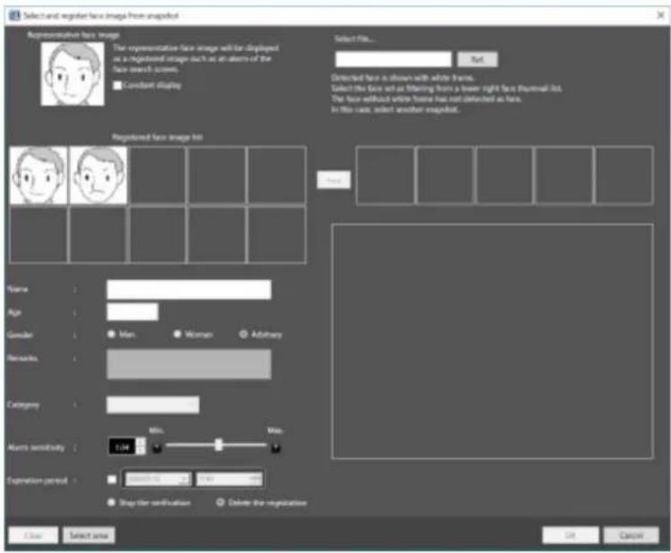
Representative face image
When 2 or more face images are registered for the same person, it is possible to set the representative face image.
The representative face image will be set as the face image to be displayed on the registered face image list table.
* When no face image data is displayed for this face image (middle of the left side), it is impossible to enter the following face information (name, age, gender, remarks, category, alarm sensitivity).
Registered face image list
A list of multiple face images registered for the same person will be displayed. Up to 10 face images can be registered.
When 5 or more face images are registered, the scroll bar will be displayed at the bottom. When right-clicking on a registered face image, "Set as the representative face image", "Delete face image" and "Check the eye position" (or "Image check") will be displayed on the right-click menu. When "Set as the representative face image" is selected, the representative face image will be displayed with a blue frame. When "Delete face image" is selected, the face image will be deleted and the face images subsequent to the deleted face image will shift to the left to fill the vacant space of the deleted face image.
When "Image check" is selected, the face image evaluation window will be displayed and the face image can be checked on it.
When "Check the eye position" is selected, the face image evaluation window will be displayed and the eye position can be checked on it.
Step 3
Click the [Ref.] button. Select an image file to be read on the file selection window.
→ The face detection from the image will start and square frames will be displayed around all the faces when face images are detected.

Step 4
Click a face image to be registered additionally from the face image list.
→ The selected face image will be displayed with a green frame.
Note:
- When selecting a face image even though 10 face images are already registered for the selected person, the warning pop-up window will be displayed.
Step 5
Click the Add button to add the selected face image to the registered face image list. The "Face image Evaluation" window will be displayed during this process. Refer to "Register from snapshot" for the face image evaluation window.
Note:
- The available right-click menu when right-clicking on the added face image are "Set as the representative face image" and "Check the eye position" (or "Image check").
Step 6
Click the [OK] button.
Display the statistical graphics of 4.7.9. age/gender/head-count 4.7.9.1. Display the statistical results
It is possible to display the statistic results of age, gender and head count for each camera.
Step 1
Click the [Age and Gender] tab on the face search window.
The age and gender window will be displayed.

Step 2
Select the start date and the period to display the statistical results in the [Event timestamp] section.

Select the start date of the period from "2005/1/1" to "2034/12/31". Select a number for the month from "1" to "12".
Step 3
Select the face search server and the cameras to display statistics in the "Camera" section.

Note:
- The cameras obtained by "Face search - server registration" of the setup window will be displayed in the tree.
- When the checkbox of "Parent node (server)" is checked, the checkboxes of all the child nodes will be checked automatically.
- When the checkbox of "Parent node (server)" is unchecked, the checkboxes of all the child nodes will be unchecked automatically.
- Up to 8 cameras can be selected.
Step 4
Click the [Generate report] button.
The statistical results will be displayed.

The following display options can be set.
■ Calendar
Select a date of which statistics are to be displayed from [Calendar].

Note:
- Only the date with data will be displayed. • Date without data will be displayed with the "x" mark.
■ Graph type
Select the graph type to be displayed from the following.
Daily trend (15-minute scale)/Daily trend (30-minute scale)/Daily trend (1-hour scale)/Weekly trend/Days trend/Monthly trend
■ [Stack]/[Ratio] buttons
Switches the graph display based on the accumulated data or the proportional data.
Note:
- The line graph is available only when displaying based on the accumulated data (stack) and the data point labels will be displayed together.
■ [By gender]/[By total] buttons
Switches the graph display based on the gender or the total number.
■ [Male]/[Female]/[Unknown] checkboxes
Check the checkbox to display the desired information in the graph display.
■ Circle graph
Select the items to be displayed with the data labels of the circle graph.
Each time clicked on the circle graph, the label display will be switched in order of [Title] → [Head count] → [Ratio] → [Title].
4.7.9.2. Download the statistics results as a CSV file
It is possible to download the data used for the statistics display as a CSV file.
Step 1
Click the [Download CSV] button on the Generate report window.
→ The folder selection window will be displayed.
Note:
- When a removable HDD formatted on the 32-bit OS is connected to a PC whose OS is the 64-bit edition, it may fail to designate the removable HDD as a saving destination.
Step 2
Select the destination folder of the CSV file to be downloaded and click the [OK] button.
The statistics data will be saved as the CSV file whose character code is UTF-8 and comma separated.
The name of the downloaded CSV file will be as follows.
"ccccccc_yymmdd000000_yymmdd000000_00_00.csv"
- cccccccc
: Camera name or "total"
■ Yymmdd000000 (1st part)
: Start date of display period (Year in last 2 digits)
■ Yymmdd000000 (2nd part)
: End date of display period (Year in last 2 digits)
CSV file format
Output example
GUID, Aggregated Date, Gender Code, Age Code, Period of time, The number of people
00200001-0000-0000-0000-192168001100,2013/07/24,1,3,0900,0
00200001-0000-0000-0000-192168001100,2013/07/24,1,3,0915,0
00200001-0000-0000-0000-192168001100,2013/07/24,1,3,0930,0
00200001-0000-0000-0000-192168001100,2013/07/24,1,3,0945,0
The data item name and the 15-minute summary information will be output on the first line and the second line respectively.
[GUID]
Camera GUID
[Aggregated Date]
Date
[Gender Code]
Gender code
-1: Unknown / 0: Male / 1: Female
[Age Code]
Age code
-1: Unknown / 1: 19 or younger / 2: 20 - 29 / 3: 30-39 / 4: 40 - 49 / 5: 50 - 59 / 6: 60 or older
[Period of time]
Time 15 minutes each
[The number of people]
Head count
Change the display setting (Hide the 4.7.10. display)
4.7.10.1. Display a face frame (Hide a face frame)
It is possible to display/hide the border frame displayed around a face when detected.
Important:
- This function will be valid only when a camera having the face search function is connected to ASM300 and the face search function is ON.
Select [ON] of [Face frame] under [Operation window display setup] of the menu of ASM300 main window. In case of live window, confirm that the checkbox on the left of [Frame display with face] in the pop-up menu displayed by right-clicking on the screen is unchecked. Then, select [Frame display with face].
→ A square frame will be displayed on the detected face.
Select [ON] of [Face frame] under [Operation window display setup] of the menu of ASM300 main window. In case of live window, confirm that the checkbox on the left of [Frame display with face] in the pop-up menu displayed by right-clicking on the screen is checked. Then, select [Frame display with face].
→ A square frame displayed on the detected face will be hidden.
Note:
- When the "Pixel by Pixel" mode is set for the image display method, the action of this function is not guaranteed.
4.8. Use the heat map display function Precautions 4.8.1.
Important:
- To use the heat map function, it is necessary to register the function extension option for image analysis (hereinafter, "this option") separately.
- Enter the following numbers for “Activation Key No.” and “Registration ID” required for registration of this option. ● Activation Key No.: 0405-0005-000B-1234 ● Registration ID: 25F4-9547
- When SSL communication is used between the camera and the PC, displaying the still picture of heat map and the still picture of people count is unavailable.
Compatible devices
| Model | Appears in this document as | Version | Compression |
| WV-SFN480 | 9M Fisheye cameras | 1.12 or later | H.264 |
| WV-SFV481 | |||
| WV-X4170 | 1.30 or later | H.265, H.264 | |
| WV-X4171 | |||
| WV-X4571L | |||
| WV-X4571LM | |||
| WV-S4150 | 5M Fisheye cameras | 1.00 or later | H.265, H.264 |
| WV-S4550L | |||
| WV-S4550LM |
Use the heat map function 4.8.2.
The heat map display function will visualize the passing and loitering density of people.
- Data will be acquired according to the specified camera, period, and area. Also the still picture of passing or loitering map will be displayed.
- Passing or loitering data can be compared easily, since the map can be switched by specified time, days (previous day/day after), or per week in data acquiring range.
- The maximum period for acquiring heat map data is one month.
- The still picture of heat map can be output.
4.8.2.1. Display still picture of heat map acquired from the specified camera
Step 1
Click the [Heat map] icon on the operation window.
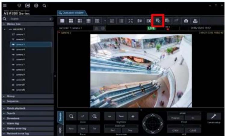
Step 2
Click the [Heat map] tab.

Step 3
Set up conditions for acquiring heat map data.

■ Camera
Select the camera to acquire heat map data. Only cameras that support the heat map function registered in ASM300 can be selected.
Note:
- If [Live image source] of the camera registered to the recorder is [Recorder], the camera will not be displayed in the camera selection area.
- When SSL communication is used between the camera and the PC, displaying the still picture of heat map is unavailable.
Period
Start: Select the start date to acquire heat map data from "2005/1/1" to "2034/12/31".
The default is a day before the set date of PC.
End: Select the end date to acquire heat map data from "2005/1/1" to "2034/12/31".
The default is the same date as the set date of PC.
Note:
- The maximum period for acquiring heat map data is one month. If over one month is specified, an error message will be displayed.
Step 4
Click the [Download] button.
→ The "Heat map data acquisition" window is displayed, and download will start.
To cancel the download, click the [Cancel] button.
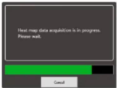
Note:
- The acquired data will be saved on the PC where ASM300 is installed. • To acquire longer period of data, the longer time is required for download.
- The data can be acquired only when the heat map function is enabled in the camera setting.
The timeline will be displayed when the download is complete.

On the timeline, the time zone where the heat map data exists will be colored.
Step 5
Select "Type" and "Display area" for displaying heat map data.
■ Type
Select the type from the following.
Passing map: Represents a traffic of moved people in colors on the screen. The more people moved, the more reddish the area becomes.
Staying map: Represents a concentration of people on the screen. The more people concentrated, the more reddish the area becomes.
■ Display area
Select the preset display area.
Note:
- Refer to "Set the heat map/people count functions" for further information about "Preset 1 setting" - "Preset 4 setting".
Step 6
On the timeline, specify the time zone for displaying a heat map image. To specify the time zone, left-click at the starting time and drag to the end time. The color of the selected time zone will be changed.

When the mouse click is released at the end time, the time zone is set and the heat map image will be displayed.
The scale of the timeline can be changed for 15 minutes, 1 hour, 12 hours, or 1 day by operating the "Change the scale" slider.

The specified time on the timeline will be displayed at the bottom of the heat map image.

4.8.2.2. Switch (jump) the display period of the heat map image
The displayed heat map image can be switched, for example, to the one with the same time zone of the previous day or a day after.
| -1W | -1D | Prev | Next | +1D | +1W |
-1 week/+1 week: Switches the displayed heat map image to the one with the same time zone of the previous week or a week after. -1 day/+1 day: Switches the displayed heat map image to the one with the same time zone of the previous day or a day after.
Precedent section/Following section: Switches the displayed heat map image to the one with the previous or following time zone.
Note:
- Only the downloaded period can be displayed.
4.8.2.3. Output heat map image
The displayed heat map image can be output in a JPEG file.
Step 1
Click the [Data output] button while displaying the heat map image to be output.
Data output
→ The "File output" window will be displayed.
Step 2
Check the saving destination and the file name for the heat map image to be output.

To change the saving destination and the file name of the heat map image to be output, proceed to Step 3. If no change is required, proceed to Step 4.
Note:
- The default file name of the heat map image will be as follows.
Example)
When outputting an image of 2015/03/10 13:00 - 18:00
heatmap_image_201503101300_201503101800.jpg
The heat map image will be saved in the size of "320x320".
Step 3
Click the [Select folder] button.
→ Specify a folder to store the file.
Step 4
Click the [Output] button.
→ The "Heat map data output" window will be displayed, and the output of the heat map image will start.
Step 5
When the output of the file is complete, click the [OK] button.

→ The window for the heat map image will be restored.
4.8.2.4. Adjust the sensitivity of heat map image
Set the maximum sensitivity for the heat map image by operating the sensitivity slider.

Move ◀ of the sensitivity adjustment slider.
Note:
• Number input is available for the sensitivity.
Use people count function 4.8.3.
The People count function visualizes the number of passing people.
- It will display a still picture, graph, or table indicating people who crossed the line of the specified camera. • The maximum period for acquiring people count data is one month.
- The displayed graph or table can be output in an Excel file, and the still image can be output in a JPEG image file.
4.8.3.1. Display still picture of people count acquired from the specified camera
Step 1
Click the [Heat map] icon on the operation window.

Step 2
Click the [People counting] tab.
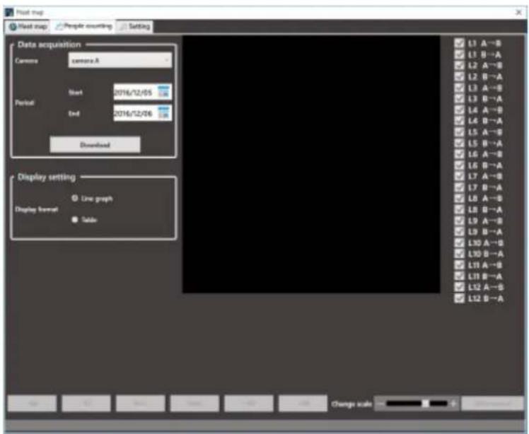
Step 3
Set up conditions for acquiring people count data.

■ Camera
Select the camera to acquire people count data.
Only cameras that support the heat map function registered in ASM300 can be selected.
Note:
• If [Live image source] of the camera registered to the recorder is [Recorder], the camera will not be
displayed in the camera selection area.
- When SSL communication is used between the camera and the PC, displaying the still picture of people count is unavailable.
Period
Start: Select the starting date for acquiring people count data from "2005/1/1" to "2034/12/31".
The default is a day before the set date of PC.
End: Select the end date for acquiring people count data from "2005/1/1" to "2034/12/31".
The default is the same date as the set date of PC.
Note:
- The maximum period for acquiring people count data is one month. If over one month is specified, an error message will be displayed.
Step 4
Click the [Download] button.
→ The "People counting data acquisition" window will be displayed, and download will start.
To cancel the download, click the [Cancel] button.

Note:
• The acquired data will be saved on the PC where ASM300 is installed. • To acquire longer period of data, the longer time is required for download. - The data can be acquired only when the people count function is enabled in the camera setting.
Step 5
The image of people count and graph will be displayed when the download is complete.
• The lines for counting people will be displayed on the image area. - The lines can be displayed or hidden with the checkbox provided for each line. To display the line, mark the checkbox. All checkboxes are marked in the default. After the checkbox status is changed, the setting will be kept when the image is displayed next time. • The graph will show the data of the line whose checkbox is marked.
Note:
• The maximum number of lines that can be specified for people count is 12 (for 24 directions). - Specify the line for people count in the setup of the camera.
4.8.3.2. How to count people in the image area
Example) When the checkboxes of "L6 A→B" and "L6 B→A" are marked

A line of "6" will be displayed in the image area and number of people moved in direction A → B and B → A will be displayed.

In the above example, "228" represents the number of people moved in the direction of A to B, and "172" represents the number of people moved in the direction of B to A.
Note:
- The correct people count may not be displayed if downloaded data contains a period where no lines are set with the camera or the number of lines or its position is changed. • Use the people count function after setting lines with the camera.
4.8.3.3. Select a time zone to display the cumulative total number
On the graph, specify the time zone for displaying the cumulative total number in the image area.
To specify the time zone, left-click at the starting time and drag to the end time.
The color of the selected time zone will be changed.

When the mouse click is released at the end time, the time zone is set and the cumulative total number will be updated.
The scale of the graph can be changed for 15 minutes, 1 hour, 12 hours, or 1 day by operating the "Change scale" slider.

4.8.3.4. Display the table of people count
Select the display format in "Display setting".

When "Table" is selected, the graph area will be changed to a table.

4.8.3.5. Select a time zone to display the cumulative total number
In the table, specify the time zone for displaying the cumulative total number in the image area.
To specify the time zone, left-click at the starting time and drag to the end time. The color of the selected time zone will be changed.
| Date | L1 A→B | L1 B→A | L2 A→B | L2 B |
| 2015/04/02 14:45 | 0 | 0 | 0 | 0 |
| 2015/04/02 15:00 | 0 | 0 | 0 | 0 |
| 2015/04/02 15:15 | 0 | 0 | 3 | 0 |
| 2015/04/02 15:30 | 0 | 0 | 2 | 0 |
| 2015/04/02 15:45 | 0 | 0 | 2 | 0 |
When the mouse click is released at the end time, the time zone is set and the cumulative total number will be updated.
The scale of the table can be changed for 15 minutes, 1 hour, 12 hours, or 1 day by operating the "Change the scale" slider.

4.8.3.6. Output data and image of people count
The displayed graph, table, and still image can be output and saved.
Step 1
Display the graph, table, and still picture to save by specifying the desired time zone.

Step 2
Click the [Data output] button.

The "File output" window will be displayed.
Step 3
Check the saving destination and the file names for the people count data and the image to be output.

To change the saving destination and the file names of the people count data and the image to be output, proceed to Step 4.
If no change is required, proceed to Step 5.
Note:
- On a PC where Microsoft® Excel® 2010 or later is installed, the file will be saved in "xlsx" format. If Microsoft Excel 2007 or later is not installed, the file will be saved in CSV format.
- The people count data will be saved in an Excel file. The default file name of the people count data will be as follows. Example) When outputting data of 2015/03/10 13:00 - 18:00 Linecount_data_201503101300_201503101800.xlsx
- The people count image will be saved in a JPEG format. The default file name for the people count image will be as follows. Example) When outputting an image of 2015/03/10 13:00 - 18:00 Linecount_image_201503101300_201503101800.jpg
- A people count image will be saved in the size of "320x320".
Step 4
Click the [Select folder] button.
→ Specify a folder to store the file.
Step 5
Click the [Output] button.
→ The "People counting data output" window will be displayed, and output of data and image will start.
Step 6
When the output of the file is complete, click the [OK] button.

→ The "People counting" window will be restored.
Set the heat map/people count functions 4.8.4.
Set up the heat map and people count functions.
Note:
- If the options are not terminated properly, the previous settings or default settings may be restored.
4.8.4.1. Set up heat map display area
Step 1
Click the [Setting] tab.

Step 2
Click one of the preset buttons ([Preset 1] to [Preset 4]) of the "Display area" in the "Heat map setting".
→ The "Area setting" window will be displayed.

Step 3
Specify an area by dragging the mouse on the image.
The specified area will be framed.

The "Area name" can be changed.
When the [Clear] button is clicked, the specified area will be cleared.
Step 4
Click the [Setting] button to set the area. The setting will be saved in the preset number selected in Step 2.
Note:
- Area setting is available for the selected camera images in the heat map window.
- Up to 4 areas can be set for camera images.
4.8.4.2. Set colors of people count
Step 1
Click the [Setting] tab. (Set the heat map/people count functions)
Step 2
Click the [Color setting] button of "Line color setting" in "People counting setting".

→ The "Color setting" window will be displayed.
Step 3
Click the color of the line to be changed. The respective color setting page will be displayed.

Step 4
Click the [Setting] button.
4.8.4.3. Set up data retention period
Step 1
Click the [Setting] tab. (Set the heat map/people count functions)
Step 2
For "Data retention period setting" in "Common setting", select a data retention period for the heat map and people count data from the following.
31 days/ 92 days/ 184 days/ 366 days

Step 3
Click the [Apply] button.
4.8.4.4. Delete data
Step 1
Click the [Setting] tab. (Set the heat map/people count functions)
Step 2
Click the [Data deletion] button of the "Deletion of data" in "Common setting".

→ The "Data deletion" window will be displayed.
Step 3
After selecting a camera whose data is to be deleted, click the [Execute data deletion] button.

→ The deletion confirmation window will be displayed.
Step 4
Click the [OK] button.

→ The heat map and people count data in the PC will be deleted.
Control a decoder 4.9.
The following operations are available for a registered decoder.
Displaying live images
Switching the screen pattern
Playing back the recorded images
Note:
• These functions will become available after the license for the WV-ASE204 is added. - Depending on the devices connected to the decoder, network status or restrictions of WJ-GXD400, images from the decoder may sometimes not be displayed or controlled. Refer to the operating instructions of the decoder for further information about the restrictions.
Select a decoder 4.9.1.
Step 1
Click the [Decoder control] icon on the title bar or select the decoder (online) icon displayed from the device tree.
→ The "Decoder control" window will be displayed.

Note:
- When the "Decoder control" window is displayed for the first time, the display will be conformed to the downloaded current decoder status. After the window is displayed once, the current status will not be downloaded until the window is closed and displayed again. Therefore, if the "Decoder control" window has constantly been displayed, the status displayed on the window may differ from the actual status of the decoder depending on the control by another user or network errors. In this case, close and display the "Decoder control" window again.
- When the "Decoder control" window is displayed by clicking the [Decoder control] icon on the tool bar, the first area specified for the decoder that is displayed at the upper-left will be selected.
- The HD300, NV200, NV300, NX-series, Video Insight Server or GXD400 icon will not be displayed in the device tree on the "Device control" window.
Step 2
Click (Select) the desired area associated with the desired decoder using a mouse.
→ The selected frame (in orange) will move.

4.9.2. Switch the screen pattern of the decoder
Select the 1-screen, 3-screen or 6-screen icon above the displayed areas associated with the decoder.
→ The screen pattern will be switched according to the selected icon, and the selected icon will turn orange.

Note:
- If the currently selected area disappears when the screen pattern is switched, the first area will be selected with the frame.
4.9.3. Display live images using the decoder
Select a camera from the device tree on the "Device control" window.
→ Live images will be displayed on the selected area associated with the selected decoder.

4.9.4. Start the audio output from the camera
Press the [Audio ON] button.
→ The audio will be output from the selected camera to the selected decoder.

Note:
- It is possible to output the audio from only one channel at a time. (The latest output has the priority.)
- When "Unknown" is displayed for the selected camera or no camera has been registered for the selected channel, the [Audio ON] and [Audio OFF] buttons will not be displayed.
4.9.5. Stop the audio output from the camera
Press the [Audio OFF] button.
→ The audio output from the selected camera will be stopped.
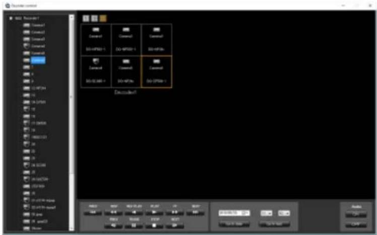
Note:
- When "Unknown" is displayed for the selected camera or no camera has been registered for the selected channel, the [Audio ON] and [Audio OFF] buttons will not be displayed.
4.9.6. Display recorded images using the decoder
Step 1
Select the desired area to play back recorded images associated with the desired decoder.
→ Playback operation panel will be displayed when the camera associated with the selected area is connected to the recorder.
Step 2
Perform one of the following.
Click the [PLAY] button on the playback operation panel.
Select the time & date and click the [Go to date] button.
Click the [Go to last] button.
→ Playback will start on the associated decoder.
Step 3
It is possible to control the following buttons when the decoder is in the playback status.
[PREV RECORD] button: Playback will start after skipping to the previous recorded image.
[REW] button: Fast reverse playback will be performed.
Playback speed for fast reverse playback will be changed in the following order each time this button is clicked: Step 2 (Approx. 4x) → Step 3 (Approx. 8x) → Step 4 (Approx. 16x) → Step 5 (Approx. 32x) → Step 6 (Approx. 48x) → Step 7 (Approx. 96x)
Note:
- The step will not be displayed on the "Device control" window. The status will be the same as normal playback. • [REV PLAY] button: Reverse playback of a recorded image will be performed.
- When playing MPEG-4 or H.264 images, some frames of recorded images may not be displayed.
- Reverse playback will be performed with the set refresh interval of the camera.
- [REW] button: Fast reverse playback will be performed.
- Playback speed for fast reverse playback will be changed in the following order each time this button is clicked:
Step 2 (Approx. 4x) → Step 3 (Approx. 8x) → Step 4 (Approx. 16x) → Step 5 (Approx. 32x) → Step 6 (Approx. 48x) → Step 7 (Approx. 96x)
- The step will not be displayed on the "Device control" window. The status will be the same as normal playback. • This software does not support the fast playback smooth mode of the ND400.
- The playback mode will be normal fast playback.
[NEXT RECORD] button: Playback or reverse playback will start after skipping to the next recorded image.
[PREV IMAGE] button: The previous frame will be displayed when this button is clicked during pausing.
- When playing MPEG-4 or H.264 images, some frames of recorded images may not be displayed.
- Reverse frame-by-frame playback will be performed with the set refresh interval of the camera.
[PAUSE] button: Playback will stop when this button is clicked during playback. Playback will resume when this button is clicked during pausing.
[STOP] button: Playback will stop and live images will be displayed.
[NEXT IMAGE] button: The next frame will be displayed when this button is clicked during pausing.
Use the download function 4.10. Download recorded images 4.10.1.
It is possible to download recorded image from the recorder onto the PC. Download recorded images using the "Download" panel.
Note:
- Recorded images of up to 128 cameras can be downloaded simultaneously. When multiple camera channels are selected, download of recorded images will be performed by the camera channels in order.
- It is possible to designate multiple recorder as download targets, However, download will not be executed simultaneously. When the same camera channel is designated, an address name will be added to the head of the file name. • The maximum recording duration available for download is 24 hours.
- For the designated download range, the separate download will be executed by the unit of 60 minutes when using NX-series and by the unit of 30 minutes when using a recorder other than NX-series respectively. • A downloaded file will be a divided file by the unit of time.
- The maximum file size is about 1.9 GB. If it exceeds 1.9 GB during downloading, download will end at that point.
4.10.1.1. Set a download target
Step 1
Click [Download] on the function panel.
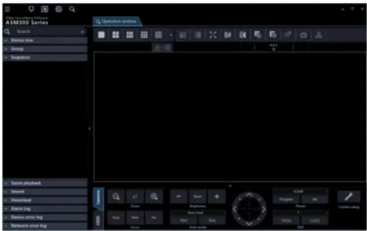
→ The download panel will be displayed.
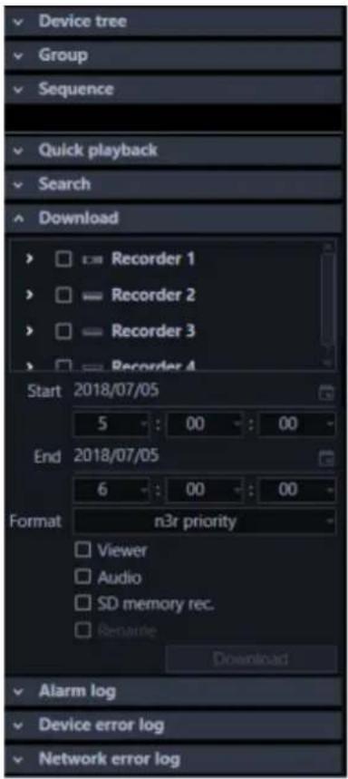
The details of the window are as follows.
- Recorder tree
Recorders and cameras as the target sources of download will be displayed. Select desired recorders and the cameras.
■ Start
Select a start time of the time range for download.
Select a number for hour from "0" - "23". Select a number for minute (1 minute step). Select a number for second (1 second step).
■ End
Select an end time of the time range for download.
Select a number for hour from "0" - "23". Select a number for minute (1 minute step). Select a number for second (1 second step).
■ Format
Select the format of the file to download from the following.
- n3r priority: Downloads an image file in n3r format.
- mp4 priority: Downloads an image file in mp4 format. If download of an image file in mp4 format is unavailable, an image in n3r format will be downloaded.
Default: n3r priority
Important:
- Refer to "Basic setup" - "n3r file download method (NX series)" for further information about the n3r file download.
- Download of images files in mp4 format is available if using NX400 (version 2.0 or later), NX300 and NX200 (version 1.1 or later). If using another model or a firmware version that is not supported to use this function, image files in n3r format will be downloaded even if “mp4 priority” is selected. The available functions vary depending on the firmware version of the recorder. Refer to the operating instructions of the recorder for further information. In the same manner, if download of an image in the specified format is unavailable, the image will be downloaded in a format supported by the recorder in use. • Use HTTP function for downloading an mp4-format image file.
- At the time of download of an image in mp4 format, the file can be downloaded as a file with audio only when “AAC” is set for the audio compression method of the camera. Audio recorded in other compression method than “AAC” will not attached to an mp4 file.
■ Viewer
The viewer software will be downloaded together with recorded images.
■ Audio
Audio will be downloaded together with images.
Note:
- When trying to download video data with interrupted audio from Video Insight Server, only video data (without audio) will be downloaded.
■ SD memory rec.
Recorded images transferred from the SD memory card in the camera to the recorder will be downloaded.
■ Rename
Change a name of a downloaded file.
Note:
- This is available only when 1 camera is selected as the download target.
■ [Download] button
The folder selection window will be displayed.
When "Rename" is selected, the file name edit window will be displayed.
Step 2
Select the recorders and the cameras as the target sources of download.
Step 3
Designate time range for download, and then click the [Download] button.
→ The window for a folder designation will be displayed.
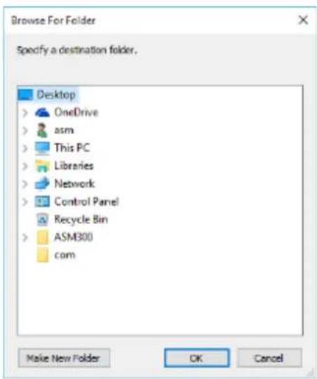
The details are as follows.
■ Destination folder
Specify a folder as the destination of downloaded files.
■ [New Folder(N)] button
Create a new folder in the folder currently selected.
■ [OK] button
The folder browse window will close and the download will start.
■ [Cancel] button
The window for a folder destination will close and the download will be canceled.
Note:
- The overwrite warning window will be displayed when a file of the same name already exists in the folder.
If you do not wish to overwrite the existing file, cancel the download and select another folder.
- When a removable HDD formatted on the 32-bit OS is connected to a PC whose OS is the 64-bit edition, it may fail to designate the removable HDD as a saving destination.
Step 4
Click the [OK] button after specifying a folder.
→ When "Rename" is not selected, move to step 5. → When "Rename" is selected, the file name edit window will be displayed.

Enter a name of a file to be downloaded and click the [OK] button.
Note:
- The file extension will automatically be added.
- If a letter is added to the head of the file name that is displayed using the initial value, it will become impossible to search using the viewer software. (However, it is possible to play it.) Refer to "Use the viewer software" for further information about the viewer software.
Step 5
Download will start and the download start window will be displayed.
Refer to "Use the download window" for further information about the download window.
Note:
- When the CD/DVD drive is selected as a saving destination, it is necessary to insert a writeable medium into the CD/DVD drive before starting the download.
- When the total file size of all the downloaded files is larger than the capacity of the CD/DVD medium, only some files that can be contained in the medium will be written.
- It is also possible to automatically play recorded images on a CD/DVD only by inserting the disc into the drive. Refer to “Create an auto-play CD/DVD” for further information.
- When the viewer software is copied, the viewer software will also be written.
4.10.1.2. Use the download window
When a download started, the download window will be displayed.
Note:
- When a download is started using the operation window, a file name that was set as the download target will be added to the download window.
- Up to 10000 files can be downloaded at a time.
- If the size of the download file exceeds the capacity of the save destination (HDD, DVD, etc.), the download is suspended and only a part of the file is saved within the range that fits the capacity.

The details of the window are as follows.
■ Name of the file currently being downloaded
Name of the file currently being downloaded will be displayed.
■ Progress bar
The current download progress status will be displayed.
■ Download status
"Number of downloaded files" / "Number of files to be downloaded" will be displayed.
■ List of files
Information of the downloaded files will be displayed in list form.
- Checkbox: Select a desired item to operate
- Recorder: A recorder name as a download target will be displayed.
- Camera: A camera name as a download target will be displayed.
- File name: A file name as a download target will be displayed. • Result: The status of the download file will be displayed.
• OK: Download of the file is successfully completed. • NG: Download of the file failed. • Now downloading: Currently downloading. • Not yet: Download is not yet executed. • No data: No data was found in the selected recorder. • Canceled: Download is canceled.
■ [< Prev] button
Moves [File information list] to the previous page.
■ [Next >] button
Moves [File information list] to the next page.
■ Number of pages
"Current displayed page"/"Total number of pages" of the file information list will be displayed.
■ [Delete] button
Delete the item selected by the checkbox.
Downloaded files will not be deleted.
■ [Retry] button
When the result of the item selected by the checkbox is "NG" or "Canceled", download will start again.
■ [Cancel] button
When the state of the item selected by the checkbox is "Download in progress" or "Not yet", download will be canceled.
Note:
- The download cancellation confirmation will be displayed. When the [OK] button is clicked, the download will be canceled. When the [Cancel] button is clicked, the download will continue.
■ [Quit] button
The download window will close.
Note:
- When the download window is closed, items whose state is “Download in progress” or “Not yet” will be deleted from the file information list. • Even if logged out or ended this software during the download, the download will be continued.
When "OK" is displayed in the result of the file information list, the download is successfully completed.
4.10.1.3. Create an auto-play CD/DVD
It is possible to create an auto-play CD or DVD that automatically plays written recorded images on the disc only by inserting it into the drive.
Note:
- When the CD/DVD drive is selected as a saving destination, it is necessary to insert a writeable medium into the CD/DVD drive before starting the download.
- When the total file size of all the downloaded files is larger than the capacity of the CD/DVD medium, only some files that can be contained in the medium will be written.
- The name of the downloaded file cannot be changed.
- The following procedures are explained by taking a new CD/DVD as an example. When the media is not brand new, it is necessary to format it beforehand.
Step 1
Click [Download] on the function panel.

→ The download panel will be displayed.
Step 2
Select the recorders and the cameras as the target sources of download.
Step 3
Designate time range for download.
Step 4
Check [Viewer], and then click the [Download] button.
The window for selecting a folder will be displayed.
Note:
• To download audio simultaneously, check [Audio]. - File names cannot be changed. Please do not check [Rename].

Step 5
Select a CD/DVD drive as the save destination folder and then click the [OK] button.
At this time, select the root (top-most directory under the drive) of the CD/DVD drive.
The "Burn a Disk" window will be displayed.
Step 6
Select "Like a USB flash drive".
Important:
- When selecting "With a CD / DVD player", the download may fail. Be sure to select "Use like USB flash drive".

Step 7
Click the [Next] button.
Formatting of the disc will start. Depending on the disc in use, the required time to format may vary.

Step 8
When the formatting is completed, the destination folder selection window will be displayed again.
Select a CD/DVD drive as the save destination folder and then click the [OK] button.
→ Download will start and the download start window will be displayed.
Refer to "Use the download window" for further information about the download window.

Step 9
When [OK] is displayed in [Result] on the download window, the download is completed. Take out the disc from the CD/DVD drive.
Important:
- If playback does not start even when inserting the completed disc into the CD/DVD drive, check if the settings of Windows are set as follows.
- Click [Control Panel] - [Hardware and Sound] - [AutoPlay] in order.
- Select "Install or run program from your media" in the [Software] - [Software and games].
- Click the [Save] button.
4.10.2. Download while playing recorded images
When "Download" is selected from the menu displayed by right-clicking on the playback window, the download panel will open. Operate as instructed in step 2 of "Set a download target" to download. Refer to "Play" for how to display the playback window.
Download using the search panel 4.10.3.
When "Download" is selected from the menu displayed by right-clicking on the search result list on the search panel, the download panel will open. Operate as instructed in step 2 of "Set a download target" to download.
Refer to "Play recorded images using the "Search" panel" for how to display the search window.
Use the quick download 4.10.4.
Recorded images on the operation window will immediately be downloaded by the method set in advance on the setup window.
Step 1
Right-click on the image display area of the operation window and select "Quick download" or "Quick download (All screens)" from the displayed pop-up menu.

The details of the window are as follows.
■ Pop-up menu
Quick download: Downloads images displayed in the selected area on the operation window. Quick download (All screens): Downloads images displayed in the all areas on the operation window.
Note:
- When using "Quick download", download will be executed according to the pre-download time and download time set in advance on the setup window. Refer to "Basic setup" for further information about the settings.
- For the designated download range, the separate download will be executed by the unit of 60 minutes when using NX-series and by the unit of 30 minutes when using a recorder other than NX-series respectively. • A downloaded file will be a divided file by the unit of time.
Step 2
The download window will be displayed and the download will start.
Refer to "Use the download window" for how to use the download window.
About the downloaded files 4.10.5.
When the file name is not changed at the time of download, the file name will be as follows.
Refer to "Set a download target" for how to change a file name at the time of download.
Example case:
01_070209121500_0515.n3r
(Channel number: 1, Start time of file: 2007/Feb/09/12:15:00, Time length of file: 5min 15sec)
When downloading from multiple recorders at the same time, the IP address of the recorder is given at the beginning of the file name.
Example case:
192.168.0.100_01_070209121500_0515.n3r
(IP address: 192.168.0.100, Channel number: 1, Start time of file: 2007/Feb/09/12:15:00, Time length of file: 5min 15sec)
Note:
- When the SD memory data is downloaded, the letter "_SD" will be attached to the time length of a file. Example) 01_070209121500_0515_SD.n3r
- File name of the downloaded audio data will be as follow. Example) 01_070209121500_0515.n3a
- The name of the file downloaded from NX-series will be displayed with 3-digit channel. Example) 001_070209121500_0515.n3r
- File extensions of the file downloaded from each recorder will be as follows.
- When downloaded from the ND200, ND300, ND400, HD600, NV200, NV300, NX400(Before firmware version 2.0), NX200(Before firmware version 1.1): n3r (n3a for audio file)
- When downloaded from the NX400 (after firmware version 2.0), NX300, NX200 (after firmware version 1.1): Selectable from n3r or mp4 (n3a for audio file)
- When downloaded from the HD300: h3r (h3a for audio file)
- When downloaded from the Video Insight Server: avi
4.10.6. Operate the downloaded file
It is necessary to use the dedicated viewer software to play and operate the downloaded files.
When "Viewer copy" on the download panel is selected at the time of a download, the viewer software will be downloaded together with images.
Refer to "Download recorded images" for further information.
4.10.6.1. Convert a file to the standard format
The n3r files downloaded from the recorder will be converted to playable files on the media player, etc.
Note:
- If the downloaded n3r file is image data recorded by other manufacturers' device, the data will be out of our support scope for file conversion. • Audio file (n3a) recorded with compression method "AAC" can not be converted.
- When a removable HDD formatted on the 32-bit OS is connected to a PC whose OS is the 64-bit edition, it may fail to designate the removable HDD as a saving destination.
- Depending on the entered image capture size, converted images may not smoothly be displayed. • After conversion, the image quality of the file will be set to the standard level.
- The frame rate after the conversion will be 30fps.
Click the [File conversion] icon on the tool bar.
The file conversion window will be displayed.

Note:
- When a user who is not allowed to convert a file logs in to this software, the [File conversion] icon will not be displayed.
The details are as follows.
■ File Name
Indicates the list of source n3r files.
■ Location
Indicates the full paths of source n3r files.
■ Output
Indicates the names of the folders to output the converted files.
■ [Select] button
Opens the folder to output a converted file.
■ Format
Select the format of converted image data.
mp4: Converts to an mp4 file.
WMV: Converts to a wmv file.
■ Resolution
Select the resolution from the following.
1920×1080/ 1280×960/ 1280×720/ 960×720/ 800×600/ 720×576/ 720×480/ 640×640/ 640×480/ 320×320/ 320×240
■ Audio
Select whether or not to load the audio (n3a) file during conversion.
On: Load the audio file.
Off: Not to load the audio file.
■ File Chain
Select whether or not to combine two or more converted files together.
On: Combine files.
Off: Not to combine files.
■ [Preview] button
The preview area will be displayed.
■ [Add] button
Select a source file.
■ [Delete] button
Delete a source file from the list of the files to convert.
■ [↑] button
Change the order of listed files to the ascending order.
■ [↓] button
Change the order of listed files to the descending order.
■ [Start] button
Start a conversion.
■ [Cancel] button
Cancel a conversion.
■ Progress bar
The conversion progress status will be displayed.
■ Conversion status
"Number of files converted"/"Number of files to be converted" will be displayed.
Step 2
Drag and drop the source n3r file into the list of files.
Note:
- It is also possible to select the file by clicking the [Add] button.
- It is impossible to convert h3r files.
- File conversion starts sequentially according to the order of the list. To combine two or more converted files together, the content of the source files should be ordered chronologically. Click the [↑]/[↓] buttons to correct the chronological order.
Step 3
Click the [Select] button to select the destination folder.

When the [OK] button is clicked, the selected folder will be displayed as the output destination. When the [Cancel] button is clicked, output to the selected folder will be canceled.
Step 4
Select an image capture size, audio and file chain options.
Step 5
Click the [Start] button.
→ File conversion will start. If the name of the converted file is the same as an existing file, the window will be displayed to select whether or not to overwrite the existing one.

When the [OK] button is clicked, the file will be overwritten.
When the [Rename] button is clicked, it is possible to change the file name.
Note:
- If selecting a system folder such as "Program Files" as an output folder, the file may not be created in the selected folder regardless of successful file conversion.
In this case, the OS virtualization function will generate a system folder and files under C:\Users\AppData\Local\VirtualStore.
Example: When a user whose user name is "asm" is trying to create files in
"C:\ProgramFiles\Panasonic", mp4 or WMV files will be generated under;
C:\User\asm\AppData\Local\VirtualStore\Program Files\Panasonic.
- The file name will be automatically determined. The file name will be the same as the conversion source but the extension will be changed from "n3r" to "mp4" or "wmv".
- The maximum size of an mp4 file or a wmv file is approx. 1.9 GB. When the size exceeds 1.9 GB during conversion, the file will automatically be divided into several files. The unique and sequential numbers will be given to these files.
- When the conversion of a file fails in the process, it will automatically be converted again into another file. However, the file will automatically be divided at the point of failure.
- When the file conversion error occurs, the details will be displayed in the message area. Refer to the " ℰ-When using File conversion" for error message
- When playing a concatenated file (multiple files combined) and playback point reaches the joint point of the file, black screen may be displayed for a moment and break the flow of video and audio.
- A file that is incapable of continuing conversion may be created depending on the specified range of "n3r" file downloading. When a file like the above is detected, "File error. Conversion canceled." Change the download start/end time and re-convert." will be displayed in the conversion status field and the conversion will forcibly be terminated even if the file conversion is in progress. When this message is displayed, change the download start/end time and download a "n3r" file again. Then, retry a file conversion using the newly downloaded file.
4.10.6.2. Converting audio of the network microphone to the standard format
The audio recorded from the network microphone can be converted to the standard format by specifying the sound collection position, two positions at maximum.
Step 1
Drag and drop the n3r file of the linked camera into the list of files.
Note:
- It is also possible to select the file by clicking the [Add] button.

Step 2
Click the [Preview] button.
→ The "Preview" area will be displayed.

The details are as follows.
■ Preview start button ( )
Starts preview.
■ Preview stop button ( )
Stops preview.
Step 3
Click

The selected file preview will be started, and the "Mic. setting" area will be displayed.

Note:
- The "Mic. setting" area will not be displayed if other than the files of the linked camera are played.
- The "Mic. setting" area will not be displayed if the image of the linked camera is other than fisheye.
- If no audio file (n3a) exists, the "Mic. setting" area will not be displayed.
- When multiple files are selected, the top file will be previewed.
- Preview is not available during conversion.
- When "OFF" is selected for both "Sound collection position 1" and "Sound collection position 2", a non-directional audio will be played.
The details of the window are as follows.
■ Mic volume
Changes the volume of the microphone.
+: Increases the audio volume.
-: Decreases the audio volume.
Note:
- The greater volume has lower audio quality. Set the volume as low as possible.
- If audio volume is too small or its quality is low, the audio sensitivity of the network microphone may not be set appropriately. Check and change the setting as required.
■ Sound collection position 1, Sound collection position 2
Sets up where to pick up the sound (sound collection position).
ON: Enables sound collection position setting.
OFF: Disables sound collection position setting.
When "ON" is selected, the sound collection position marker will be displayed and audio will be collected in the direction of the marker.

It is possible to move the sound collection position by dragging the sound collection position marker.
It is possible to move the sound collection position by dragging the sound collection position marker.
Selects the noise reduction level for the microphone.
Selects the noise reduction level for the microphone.
Low: Regular noise reduction.
Off: Disables the noise reduction.
Note:
- When "High" is selected, the noise will be reduced compared to "Low". However, the audibility may drop due to sound strain. Select the level according to the audibility.
- When "High" is selected, the noise will be reduced compared to "Low". However, the audibility may drop due to sound strain. Select the level according to the audibility.
■ Voice clearness
Selects the audio compensation level for the microphone in order to make better sound.
High: High level compensation.
Low: Regular compensation.
Off: Disables the compensation.
Step 4
After specifying a sound collection position, click

Step 5
Click the [Select] button to select the destination folder.

When the [OK] button is clicked, the selected folder will be displayed as the output destination. When the [Cancel] button is clicked, output to the selected folder will be canceled.
Step 6
Set up "Image Size", "Audio", and "File Chain".
Note:
- Select "On" for "Audio". When "Off" is selected, the audio will not be converted.
Step 7
Click the [Start] button.
→ File conversion will start.
Note:
- When "Off" is selected for both "Sound collection position 1" and "Sound collection position 2", a non-directional audio will be converted.
- The items set in the "Mic. setting" area will be commonly set for all the selected files. • The sound collection position marker will not be displayed in the preview window during conversion.
Use the viewer software 4.11.
When an image or an audio is downloaded, an image file ("file name".n3r, "file name".h3r) or an audio file ("file name".n3a, "file name".h3a) will be downloaded. The downloaded image data and audio data can be played, saved, or printed using the viewer software copied at the same time when the data was downloaded.
Note:
- Viewer software to be copied differs depending on the file to be downloaded. In case of n3r file: NX_Viewer.exe In case of h3r file: Viewer.exe
- The images of windows shown below for the following procedures are NX_Viewer.exe.
4.11.1. Install the viewer software
Note:
- When an older version of the viewer software is installed, uninstall it first and install a new version.
- It is unnecessary to install "Viewer.exe".
Step 1
Double-click the downloaded installer file "n3vsetupnx.exe".
The installer will be launched. Follow the instructions displayed on the monitor.
Note:
- Read the content of the "License Agreement" window and select "I accept the terms in the license agreement".
- It is possible to install the software even when "User Name" and "Organization" on the "Customer Information" screen are blank. Select [All users who uses this computer (A)].
- Select [All] for the setup type.
Step 2
Click the [Install] button.
Installation will start. When the installation is successfully completed, the installation completion window will be displayed. Click the [Finish] button.
Uninstall the viewer software 4.11.2.
Note:
- It is unnecessary to uninstall "Viewer.exe". Delete the file directly.
Step 1
Execute [Programs - Uninstall a program] in the control panel.
Step 2
Select "NX_Viewer" from the presently installed programs and click the [Uninstall] button.
The uninstall program will be launched and the wizard will be displayed.
Step 3
Uninstall the program by following the displayed instructions.
4.11.3. How to use the viewer software (NX_Viewer)
Note:
- The viewer software to be used differs depending on the file to be played. For files with the extension "n3r": NX_Viewer.exe. For files with the extension "h3r": Viewer.exe.
- It is impossible to play only an audio file (extension: h3a) using the viewer software.
- When NX_Viewer is started up for the first time, the license agreement screen will be displayed. Read the content of the "License Agreement" window and select "I accept the terms in the license agreement".
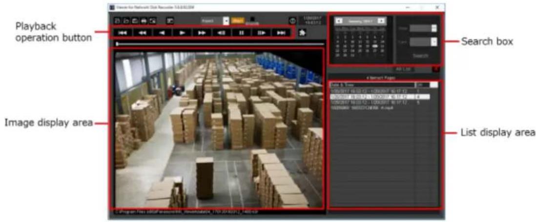

Playback operation window when images are displayed on a full screen
4.11.3.1. Select recorded images currently being played
Step 1
Click the Button (Open).
The "Open" window will be displayed.

Step 2
Select the downloaded image data ("file name".n3r or "file name".mp4) and click the [Open(O)] button. Or drag and drop the image data file into the viewer software without displaying the "Open" window.
The information of the selected file will be displayed in the list display area.
Date & Time: Indicates a start time and an end time of image data.
CH: Indicates a camera number.
Note:
- Do not change the file name of the copied or downloaded image data. If the file name is changed, the file information will not be displayed correctly.
- It is possible to select multiple files (up to 100 files) by clicking the desired files while holding down the [Ctrl] key or the [Shift] key on the user keyboard and display all of them in a list by drag & drop.
- The files can be sorted by start time and date in ascending or descending order by clicking the header
of the list display area.
- To add image data to the list display area, right-click the list and select [Add file] from the menu displayed. When the "Open" window is displayed, operate as instructed in step 2. The added image data will be displayed in the list according to the sort state of the list.
- When the number of displayed image data files has reached 100, no more files can be added. The total number of image data files will be displayed above the list as [ \~ Items].
- When the ✗ button is clicked, display of all data in the list will be deleted. Another way to clear the list is to right-click the list and select [Clear all list].
- When there is data in the same directory where there is the viewer software or in the "data" folder of the same directory, the data will automatically be loaded for playback.
4.11.3.2. Play recorded images
Use the playback operation button to play downloaded images. If an image from the same camera is displayed on the list, the next image in playback mode or the previous image in reverse playback mode will be played back consecutively. If the same camera channel is absent on the list, playback will stop, the image display area will turn black and the unit is paused.
Note:
- When starting playback of password protected data, the password entry screen will be displayed. Enter the set password.
- When the ▶ button is clicked during playback (or the ◀ button during reverse playback), the next (or previous) image of the camera currently being used for playback will be played.
- When the 📄 button is clicked, the displayed image will be enlarged. When the 📄 button is clicked, it will return to its original size.
- If there is audio data ("file name".n3a), the / buttons will be displayed. It is possible to switch between play/mute audio using these buttons.
- When WV-ASM300 and the viewer software are launched and running at the same time, audio may not be played properly. To properly play audio, launch and run only one of WV-ASM300 and the Viewer software.
- Playback images and audio may sometimes not be synchronized exactly.
- When the [Search] button is clicked after selecting date, time and [Cam] in the search box, playback of an image data that matches with the selected time and date among data of the selected camera will start from the top of the data.
- When the 📄 button is clicked, images will be displayed on a full screen. Clicking the [Restore] button on the operation window or pressing the [Esc] key on the keyboard will return the image display to the previous status.
4.11.3.3. Save a still image
The still image displayed on the image display area can be saved as a JPEG file on the PC.
Step 1
Click the

→ The "Save As" window will be displayed.

Step 2
Enter a file name and select file type (Initial: JPEG). Confirm the destination folder and click the [Save(S)] button.
The image data will be saved.
Note:
- When using Viewer.exe, it is possible to save as a bitmap file by selecting "BMP (*.bmp)".
4.11.3.4. Save image data (copy) (NX_Viewer only)
The selected image data ("file name".n3r or "file name".mp4) can be copied in any desired folder on the PC.
Step 1
Right-click the list and select [File Operation] from the menu displayed.
The "File Operation" window will be displayed.

Step 2
Select [File output (Copy)] and click the [Start] button.
The "Save as" window will be displayed.
Note:
- When outputting password protected data, please select [File output (Decryption)].
Step 3
Confirm the file name and the destination folder, and then click the [Save(S)] button.
The image data will be copied and saved.
Note:
- It is not possible to operate the viewer software while copy is in progress.
4.11.3.5. Print the downloaded image
Print the image displayed in the image display area.
Pause playback at a desired point to print and click the 📋 button. When printing the image of an n3r file, time & date when the image is paused will be printed together.
Note:
- When using Viewer.exe, it is possible to select a print size from L/M/S.
4.11.3.6. Alteration detection
It is possible to detect the alteration of the data if a code for the alteration detection has been attached to the downloaded data.
Step 1
Right-click the list and select [File Operation] from the menu displayed.
→ The "File Operation" window will be displayed.

Step 2
Select [Integrity check] and click the [Start] button.
→ The "Input certificate file for integrity check" window will be displayed.
Step 3
Click the [Browse certificate..] button.
→ The "Open" window will be displayed.
Step 4
When opening a file with a code for the alteration detection, the certificate information will be displayed.
Please check the contents and click the [OK] button.
→ Starts alteration detection and displays the result in a window.
4.11.3.7. Display Single/Quad PTZ image converted from fisheye images
A fisheye image captured by a fisheye camera can be displayed in the single PTZ or quad PTZ format. (Hereinafter referred to as "fisheye image display change function")
Important:
- To use the fisheye image display change function, download the conversion library from the following URL and install it on the PC on which the viewer software is used. https://security.panasonic.com/support/info/
- Refer to the provided appendix paper “For customers who uses the function extension option for fisheye network camera” for supported models.
When an image to which the fisheye image display change function is applied is selected, the buttons will be displayed.


Click and select the display format.
Note:
- Clicking the button will reset the corrected image to the original fisheye image.
- Clicking the button will convert an image to a Single PTZ image.
- Clicking the 📋 button will convert an image to a Quad PTZ image.
- When clicking on an image that is converted into a Single/Quad PTZ image, the image will be displayed while locating the clicked point at the center of the screen.
Alarm/event notification 4.12.
A pop-up window (notification window) will be displayed on the operation window when an alarm or an error occurred.
An alarm notification is a warning message from a sensor or a camera, whereas an event notification is an error message that informs an occurrence of a device error and a network error.
Important:
- It is necessary to configure the settings of a device to be used in order to use the alarm/event notification function.
- When also using the Panasonic alarm protocol function of the recorder, it is necessary to set the same number to the event action number and the recording camera number on the recorder. • Refer to the operating instructions of the recorder for how to configure the settings.
Note:
- Only when an event is a terminal alarm, it is unnecessary to set the same number to the terminal number and the recording camera number since the information of the recording camera configured for the terminal alarm setting on the recorder is used. Refer to the operating instructions of the recorder in use for how to configure the terminal alarm settings.
- In case of HD600, it is possible to select two or more recording cameras. This software uses a camera whose number is the smallest recording camera number.
- When the terminal alarm setting has been changed on the recorder, it is necessary to acquire the information from the recorder. In addition, when using information of data that is acquired from a
recorder using WV-ASM100 series (Version 7 or earlier), it is necessary to acquire the information from the recorder again.
• Live images from the camera in which an alarm occurred can be displayed only when the login user is allowed to access this camera.
- Images recorded at an alarm occurrence can be played only when a login user is not restricted by the user level determined by the administrator to play the recorded images.
When an alarm/event notification is provided, one of the following logs will be filed.
Alarm log: Alarm information history transmitted using Panasonic alarm protocol from devices Device error log: Device error information history transmitted using Panasonic alarm protocol from devices
Network error log: Network error history between this software and devices
4.12.1. Alarm/event notification message
When an alarm/error occurred, an alarm notification message or an event notification message will be displayed in the operation window. It will be displayed at the bottom right of the operation window. The newest one will be displayed at the top and follows in descending order. When a message window displayed at the bottom is closed, message windows above the closed window will move down.
Note:
- When a same type message is displayed while a message window is being displayed, the message in the message window will be updated.

■ Alarm notification message
Notifies of an alarm occurrence.
■ Event notification message
Notifies of an event occurrence.
Note:
- When an alarm/event occurred during the sub window such as the "Search" window is displayed, the buttons on the displayed message window are inoperable until the displayed sub window is closed.
4.12.1.1. About the alarm notification message
When an alarm occurred, the alarm notification message window will be displayed. When an alarm occurred, the alarm buzzer will start sounding and the alarm notification message window will be displayed. When the window is closed, the alarm log panel will be displayed.
When an alarm notification is provided from the recorder during the alarm notification message window is displayed, the descriptions in the notification message window will be renewed and the latest alarm information will be displayed.

■ Alarm notification message
Alarm information, time & date of the alarm occurrence, the title of the recorder/encoder (that provided the notification) and the title of the camera will be displayed.
Note:
- When the device that provided an alarm notification is a camera, "--" will be displayed as the title of the device.
- When an alarm occurred in a Fisheye camera and the camera is in "4-stream" mode, "Camera name" for device title and "CH type" for camera title will be displayed respectively.
- When an alarm notification is provided from Video Insight Server, the recorded image may not be displayed by clicking the [Play] button right after the alarm is notified because the data has not being stored.
■ Number of alarm occurrences
Total number of alarm occurrences will be displayed. When the total number of the alarm occurrences exceeds 1000, "1000<" will be displayed.
■ [Live] button
The alarm notification message window will close and live images from the camera in which the alarm occurred will be displayed on a 1-screen.
■ [PLAY] button
The alarm notification message window will close and playback of recorded images on a 1-screen will start from the point of 5 seconds before the alarm occurrence.
Note:
- When it is just after the alarm occurrence, playback may not start from the point of 5 seconds before the alarm occurrence.
- Depending on the settings of the recorder, playback may not start from the point of 5 seconds before the alarm occurrence.
- When an alarm notification is provided from an encoder or a camera that is not registered in the recorder, the [PLAY] button will not be displayed.
■ [Close] button
Closes the alarm notification message window. When the window is closed, the alarm log panel will be displayed.
4.12.1.2. About the event notification message
The event notification message window notifies of a device error or a network error occurrence. When an error occurred, the alarm buzzer will start sounding and the event notification message window will be displayed. When the window is closed, the "Device error log" panel or the "Network error log" panel will be displayed.
When an event notification is provided from the recorder during the event notification message window is displayed, the descriptions in the notification window will be renewed and the latest event information will be displayed.

■ Event notification message
Error information, time & date of the error occurrence, the title of the recorder/encoder (that provided the notification) and the title of the camera will be displayed.
Note:
- When the device that provided an error notification is a camera, "--" will be displayed as the title of the device.
- When an alarm occurred in a Fisheye camera and the camera is in "4-stream" mode, "Camera name" for device title and "CH type" for camera title will be displayed respectively.
■ Number of error occurrences
Total number of the error occurrences will be displayed. When the total number of the alarm occurrences exceeds 2000, "2000<" will be displayed.
■ [Close] button
The error notification message window will close. When the window is closed, the "Device error log" panel or the "Network error log" panel will be displayed.
4.12.2. Alarm mode display of the live window
When the live window is active and "ON" is selected for "Alarm camera direct live window", the live window will be switched into the alarm mode and display live images from the camera in which the alarm occurred when receiving an alarm notification.
When received an alarm notification from a camera used for the alarm linkage function and whose alarm type is registered for the alarm linkage function, live images will be displayed according to the contents of the set group display.
The live window will automatically be switched into the alarm mode regardless of the current status (sequence display, group display, minimized, full screen display) of the live window.
Note:
- Alarm mode display of the live window will be performed on a screen selected for the "Maximum number of areas" setting (1-screen/2A-screen/2B-screen/3A-screen/3B-screen/4-screen/4E-screen/5-screen/6-screen/7-screen/7A-screen/9-screen/10-screen/13-screen/16-screen/25-screen/36-screen/49-screen/64-screen) of the "Alarm] setting". Only an administrator can configure "Maximum number of areas" of "Alarm camera direct live window". Refer to "Alarm setting" for further information about the settings.
- When the number set for "Maximum number of area" of "Alarm camera direct live window" is more than the number set for "Live window (multi-screen) with the maximum number of areas", images will be displayed on a screen set by "Live window (multi-screen) with the maximum number of areas". Only an administrator can configure the "Live window (multi-screen) with the maximum number of areas" setting.
- When the live window is not opened, the alarm camera direct live window function will not be performed.
- When the number of multi-screen areas of the group that is set for the alarm linkage setting is more than the maximum number of areas for Live window 1, the group display will not be performed. Live image from the channel in which an alarm occurred will be displayed.
- Even after the license for the WV-ASE202 is added and while more than one live window are being displayed, the alarm camera direct live window function will be performed only on a Live window (1).
When the live window is active
• In normal operation
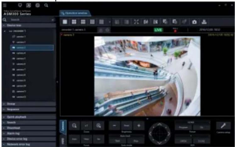

• In an alarm status

Note:
- The display position and the window size of the live window when it is started will be the same as of the last time the live window is closed.
- When the set time (auto reset wait time) has passed after the live window shifted into the alarm mode, the live window returns to the previous operation. Only an administrator can configure the "Auto reset wait time" setting.
- Refer to "Alarm setting" for further information about the settings.
- When alarms occurred sequentially before the alarm is reset automatically, live images from the cameras will be displayed in from the upper left area in order.
- When the number of alarm occurrence exceeds the maximum number of areas, the areas will be overwritten from the upper left one in order of alarm occurrence.
4.12.2.1. Simultaneously display live images of two or more alarms when alarms occurred sequentially
Depending on a screen selected for "Maximum number of areas" of "Alarm camera direct live window", the alarm mode display will differently be displayed. When "1-screen" is selected, images will be displayed in order of alarm occurrence. However, when a screen other than "1-screen" is selected, the screen will shift as follows.
Note:
• 25-screen or more will become available after the license for the WV-ASE202 is added.
- The following are descriptions of how this software works when received an alarm from a camera for which the alarm linkage function setting is not configured and the function is not active. When the alarm linkage function setting is configured and the function is active, images will be displayed on the specified multi-screen and be switched according to the configured settings.
- When received an alarm from a camera for which the alarm linkage function setting is not configured and the function is not active while displaying images by the alarm mode display triggered by the alarm linkage function, only images of the latest received alarm after switching the screen selected by "Maximum number of area" of "Alarm camera direct live window" will be displayed.
When "4-screen" is selected for "Maximum number of areas" of "Number of alarm camera direct live window"
Alarm images will be displayed in the order shown in the following diagram. When the number of alarm occurrences exceeds the number of areas, the upper left area will be overwritten.
![graph LR A["1 2\n3 4"] -->|Alarm 1 occurred| B["1 Black screen"] B -->|Alarm 2 occurred| C["1 Black screen"] C -->|Alarm 3 occurred| D["5 2\n3 4"] E["1 2\n3 Black screen"] -->|Alarm 4 occurred| F["1 2\n3 4"] F -->|Alarm 5 occurred| G["5 2\n3 4"]](/content/2026/06/1353903/images/cf44425808b289021fb892a4c30a895407b7d0a202b9aac7637b71b67bbe4d83.jpg)
4.12.2.2. Information display area
When the live window is in alarm mode, alarm information will be displayed in the information display area.
Note:
- In alarm mode, the group information display area will be hidden and the camera information display area will be displayed, regardless of their display/hide settings.
- When returning from alarm mode to the normal live window, the information display area will also return to its previous state. (If the group information display area or the camera information display area is set to be hidden, it will be hidden.)
- Alarm icon
The alarm icon window will be displayed when the live window is in alarm mode.
■ Camera name
The name of the camera from which images are currently being displayed will be shown.
■ Alarm description
Descriptions of the alarm will be displayed.
4.12.2.3. Reset the alarm mode
When a time period as the auto reset wait time set by an administrator has passed, the alarm mode will be reset and return to the normal state before the alarm occurrence. If an alarm occurs before the alarm is reset automatically, the live window will remain in alarm mode until the set time has passed from the moment the new alarm occurred. When alarms occur sequentially, the alarm mode will continue until the set time has passed from the moment the newest alarm occurred.
When "Alarm mode reset" is selected from the pop-up menu displayed by right-clicking on the image display area, the alarm mode can be reset even if the set time has not yet passed.
Function panel
Frame display with face
Alarm mode reset
Full screen
■ Function panel
It is possible to switch between displaying and hiding the function panel of the live window.
■ Frame display with face
It is possible to display or hide the border frame displayed around a face when detected.
■ Alarm mode reset
The live window will return to the previous operation mode.
■ Full screen
In a similar manner to the normal display, it will be changed to the full screen mode.
4.12.2.4. Emergency recording input alarm
In the state of emergency, emergency recording will sometimes be performed manually using the external switch. In this case, the emergency recording input alarm will be notified. An emergency recording input alarm usually contains information of multiple channels, and they will be filed as logs in the respective alarm log panel. However, only information of the largest channel number will be displayed in the alarm notification window.
Alarm mode of the map window 4.12.3.
When receiving an alarm, the icon of the camera in which an alarm occurred will blink red. The camera icon will start blinking red for 10 seconds and then displayed in red without blinking. When the icon displayed in red (or blinking red) is clicked, live images from the camera will be displayed in the selected area of the operation window and the camera icon will return to the normal camera icon.
The map operation may vary depending on the setting for "Auto change of map".
ON: Change to a map in which a camera at an alarm occurrence is registered.
OFF: The map will not be changed.

Note:
- When alarms occurred sequentially (within less than 1 second), the map will not be changed even if "ON" is selected for "Auto change of map".
- When the [Live] button or the [Play] button on the alarm notification window is clicked, images from the corresponding camera will be displayed and the respective camera icon that has been displayed in red or blinking red will return to the normal camera icon.
5. System controller (WV-CU950)
This software can be operated using an optional system controller.
The following are descriptions of the available functions using the system controller and of how to operate. It is possible to restrict operable functions according to the user type (administrator or the registered users).
Important:
- Operation response may be slow when comparing with an analog system since operations are performed via a network. • Turn on the power of the system controller after confirming that this software started up.
- Use a LAN cable to connect between the PC and the system controller. When not using a LAN cable, a connection error may occur.
- When the [ADJUST] button is pressed, a connection error with the system controller may occur.
Set a system controller 5.1.
When using the 10/100 Base-T connector to connect between a PC on which the WV-ASM300 series is installed and WV-CU950 and controlling WV-ASM300 series by operating WV-CU950, it is necessary to change the settings of WV-CU950.
Edit the settings by following the procedures below.
5.1.1. MODE Switch Setting
Set the mode switch on the rear of WV-CU950 to the Ethernet mode. The setting of the switch shall be made when the power is off. Set as shown in the diagram below.

5.1.2. Set a controller number
Use without changing the controller number from "1 (factory default position)".
5.1.3. Network Setting
Before performing the network setting, set the MODE Switch setting to the Ethernet mode.
Step 1
Turn on the power while holding down the 0, MON (ESC), and CAM (SET) buttons.
"Admin Password" will appear on the LCD to enter the password.
IP Addr Setup Mode Admin Password ____
Step 2
Enter the administrator password using the 10-key pad. The entered password will be displayed in asterisk "*"
CLEAR
When the □ button is pressed, the entered number will be deleted.
IP Addr Setup Mode
Admin Password

Step 3
Press the CAM (SET) button. The setting item selection window will be displayed.
Step 4
* Items that can be set are as follows.
| Display | Description |
| IP Address192. 168. 0. 210 | The IP address of system controllerThe factory default is "192.168.0.210". |
| Subnet Mask255. 255. 255. 0 | Set the subnet mask of system controller.The factory default is "255.255.255.0". |
| Gateway192. 168. 0. 1 | Set the default gateway of system controller.The factory default is "192.168.0.1". |
| Keyboard ID1 | (No need for setup) Remain the factory default.Default: 1 |
| Server IP Address192. 168. 0. 200 | Set the IP address of the PC on which the WV-ASN300 series is installed.The factory default is "192.168.0.200". |
| Server ID1 | (No need for setup) Remain the factory default.Default: 1 |
Step 5
Press the CAM (SET) button on the screen of the desired item to set.
Step 6
When setting IP Address, Subnet Mask, Gateway and Server IP Address, enter addresses (nnn.nnn.nnn.nnn) using the 10-key pad.
Server IP Address
- 210
The blinking part can be changed. Move the cursor onto a number to change and enter a number using the 10-key pad. The selected number using the cursor will change to the number entered using the 10-key pad.
The cursor moves left and right using

CLEAR
To edit the entered value, press the □ button to clear the value of the digit.
Enter numerical values of 0 - 255 for nnn.
Step 7
Press the MON (ESC) button.
The selected parameter will be determined, and the LCD display will return from the editing mode to the display mode. (Step 4)
Step 8
After you have completed the settings, turn off the power.
5.2. Operation using the system controller
Note:
- [ ] indicates the button. When "+" exists between the buttons, press both the buttons at once. When the indication "→" exists after an operation, the next operation is required to complete the operation.
- ▼▲◀▶ displayed in [Joystick], [JogDial], [Shuttle ring], [Zoom knob] indicate the operation direction of each interface.
Basic 5.2.1.
| Function | Operation of the WV-CU950 | Description |
| Number/numeric value entry | ||
| Cancel the entry | [CLEAR] | |
| Camera selection | Camera number entry → [CAM(SET)] | The live image of the selected camera will be displayed on a 1-screen on the operation window. It is necessary to set the camera number on the setup screen in advance. |
| Switching of camera channel | [+] | Operable only during live image display. It is necessary to set the camera number on the setup screen in advance. |
| <Operation during live image display> | [+] | Images from the camera of the next camera number will be displayed. |
| Display images from the next camera | [-] | Images from the camera of the previous camera number will be displayed. |
| Display images from the previous camera | ||
| Group selection Entry of group number → [RECORDER] | The selected group will be displayed on the operation window. It is necessary to set the group number on the setup screen in advance. | |
| Sequence selection Entry of sequence number → [TOUR SEQ] | The selected sequence will be started on the operation window. It is necessary to set the sequence number on the setup screen in advance. | |
| Sequence stop | [SEQ PAUSE] | |
| Screen pattern change | [MULTI SCREEN] | The screen pattern of the operation window changes every time the button is pressed. |
| 1-screen display | [F1] | The screen of the operation window is changed to the 1-screen pattern. |
| 4-screen display The operation window will be switched to 4-screen. | The screen of the operation window is changed to the 4-screen pattern.The displayed 4-screen is changed in order of 4A → 4B → 4C → 4D every time the button is pressed. | |
| 9-screen display | [F3] | The screen of the operation window is changed to the 9-screen pattern. |
| 16-screen display | [F4] | The screen of the operation window is changed to the 16-screen pattern. |
| Acknowledge the alarm [ACK][ALM] | The same operation will be performed as when the [Play] button on the alarm notification window is clicked.The same operation will be performed as when the [Live] button on the alarm notification window is clicked. | |
| Reset an alarm | [ALM RESET] | The same operation will be performed as when the [ALM] button on the status bar is clicked. |
| Determine | [ENTER] | The same operation will be performed as when the [Enter] key of the PC keyboard is pressed. |
| Cancel | [MON(ESC)] | The same operation will be performed as when the [Esc] key of the PC keyboard is pressed. |
5.2.2. Operating the cameras
| Function | Operation of the WV-CU950 | Description |
| Registration of the preset position | Preset number entry →[SHIFT] + [PRESET] | |
| Move the camera to the preset position | Preset position numberentry → [PRESET] | When no preset position number is entered, the camera will move to the home position. |
| Pan/tilt | [Joystick ▼▲◀▶] | The displayed image will move to the direction in which the joystick is tilted. |
| Adjust the brightnessSet brighterSet darker | [IRIS OPEN][IRIS CLOSE] | Adjustment of the brightness will continue until the pressed button is released. |
| Adjust the focal pointSet fartherSet nearerPerform the auto focus function | [FOCUS FAR][FOCUS NEAR][TOP] | Adjustment of the focal point will continue until the pressed button is released. |
| Adjust the zoomAdjust the zoom to the "wide" sideAdjust the zoom to the "tele" side | [Zoom volume ◀][Zoom volume ▶] | Zooming will continue until the zoom knob is being rotated. |
| External control 1/2< Latch mode>Set AUX1 to ONSet AUX1 to OFF | [External control 1 ON][SHIFT] + [External control1 ON] display, set to the latch | The mode setting can be configured on the receiver. (Only the latch mode is available for the cameras.)When setting for an event such as the sequencemode.Operation for "AUX2" can be performed in the same manner as for "AUX1". |
| Auto modeStart the auto modeStop the auto mode | [A][B] | |
| Auto trackStart auto track | [TOP] | This function is available when "ON" is selected for "Auto track". |
| WiperStart the wiper actionStop the wiper action | [WIPER][SHIFT] + [WIPER] | Controls the washer and wiper of WV-SUD638.The item selected in "Wiper" on the "Camera" tab in the camera operation panel will be performed. |
5.2.3. Operating a recorder
| Function | Operation of the WV-CU950 | Description |
| Start recording manually<Operation during recording>Stop the manual recording | [REC][SHIFT] + [REC] | |
| Playback of recorded images | [PLAY/PAUSE] | |
| Pause | [SHIFT] + [PLAY/PAUSE] | |
| FF | [Shuttle ring] | |
| REW | [Shuttle ring] | |
| NEXT IMAGE | [JogDial] during pausing | |
| Reverse frame playback | [JogDial] during pausing | |
| NEXT RECORD | [JogDial] while holding down [SHUTTLE HOLD] | |
| PREV RECORD | [JogDial] while holding down [SHUTTLE HOLD] | |
| Go to last | [GO TO LAST] | |
| STOP | [STOP] | |
| SKIP | [+] | |
| REV SKIP | [-] |
6. Concurrent User License Kit (WJ-NXC05W) Precautions 6.1.
Important:
- To use the functions of the "Concurrent User License Kit", it is necessary to separately purchase the license WV-NXC05W. It is also necessary to preliminarily register the additional license WJ-NXC05W in the recorder in use.
Compatible devices
| Model | Appears in this document as | Version |
| WV-NX400 | NX400 | 2.1 or later |
| WV-NX300 | NX300 | 2.0 or later |
| WV-NX200 | NX200 | 2.0 or later |
6.1.1. Functions of the "Concurrent User License Kit"
![graph TD A["License recorder"] --> B["Network"] B --> C["License"] C --> D["PC in which the software is installed"] D --> E["ASM300 in operation"] C --> F["PC in which the software is installed"] F --> G["These PCs cannot use ASM300 until the ASM300 in operation releases the license."] C --> H["PC i…](/content/2026/06/1353903/images/3ae93586e4b0cf4fc52675daf95cbb57eb6c826fa66f33f06d67abc72533a996.jpg)
- This software can be installed on up to 5 PCs using a single "Concurrent User License Kit". Only a single ASM300 can be used simultaneously.
- All the basic functions of ASM300 will become available by registering this license. However, the extension software except "Heat map" is unavailable.
- To use the ASM300 to which the license is applied, the corresponding PC is required to connect to the license server (license recorder). When this software is launched, a license will automatically be obtained from the license server (license recorder) and operation of this software will become available. The license will be released when this software is exited.
6.1.2. From installation to start of operation
![graph TD A["Installation of this software"] --> B["Launching of ASM300"] B --> C["Obtain the license (Registration Key)"] C --> D["Register the license (Registration Key)"] D --> E["Register the administrator"] E --> F["Local login (setup window)"] subgraph Section 1 A -->|Refer to "Installation".|…](/content/2026/06/1353903/images/7cc03f11a9e5d794af4b9510f931c730ccd1c7ef602d47a631d5efe0dcad7597.jpg)
Setting
![graph TD A["License recorder setting"] --> B["Registration of license"] C["Communication setting"] --> B D["Login to this software with Concurrent User License"] --> B E["Refer to "Recorder setup"."] --> B F["Refer to "Communication setup"."] --> B G["Refer to "Registration…](/content/2026/06/1353903/images/59f87bfc9325d80a1ad50efe3fddf87c6e06376de35cb53b9895c14109104f61.jpg)
6.2. Setting relating to the license recorder 6.2.1. Local login (setup window)
Launch the setting window for using the "Concurrent User License Kit".
Important:
- The setting window can be launched only by an administrator of this software.
Step 1
Launch this software.
→ The log-in window will be displayed.

The details of the window are as follows.
■ User name
Enter the user name of this software.
■ Password
Enter the password of this software. The entered password will be displayed as "●".
■ License recorder selection
Select a destination recorder to obtain the license. When [Local login (setup window)] is selected, the license recorder setup window will be displayed.
■ Change password
Check this check box to change the password of this software.
■ [OK] button
The window will shift to the license recorder setup window, the operation window or "Change password" window according to the entered content.
[Cancel] button
Click this button to cancel the entries and terminate this software.
Step 2
After entering "User name" and "Password" on the login window, select [Local login (setup window)] as "License recorder selection" and click the [OK] button.
→ The license recorder setup window will be displayed.
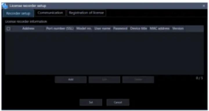
Note:
- To close the license recorder setup window after completing the setting, click the [×] button on the title bar of the window.
Recorder setup 6.2.2.
Set up the license recorder.
6.2.2.1. Register the license recorder
Step 1
Display the license recorder setup window.
Step 2
Click the [Recorder setup] tab.
→ Recorder setup window will be displayed.

The details of the window are as follows.
■ Device list
Information of the license recorder in this software will be displayed in list form.
| Item | Description |
| Check box | Select an operation target device.Default: (No checked) |
| Address | Address of a device will be displayed. |
| Port number (SSL) | A port number of a device will be displayed. |
| Model no. | A model number of a device will be displayed. |
| User name | The administrator name of a device will be displayed. |
| Password | The password will be displayed in “●”. |
| Device title | The title of the device to display with this software will be displayed. |
| MAC address | A MAC address of a device will be displayed. |
| Version | Firmware version of a device will be displayed. |
■ [Add] button
The license recorder registration window will be displayed.
Refer to "Register the license recorder" for further information.
■ [Edit] button
The license recorder registration window of the device selected in the device list will be displayed. Refer to "Edit the registered license recorder" for further information.
■ [Delete] button
The device selected in the device list will be deleted.
Refer to "Delete the registered license recorder" for further information.
■ [Set] button
The configured settings will be saved.
■ [Cancel] button
The configured settings will not be saved and close the license recorder setup window.
Step 3
Click the [Add] button.
→ The license recorder registration window will be displayed.
![License recorder registration Be sure to enter the required information first before clicking the [Download of device information] button. When using a proxy server, configure the "Basic setup" setting under "Communication". Address Enter IP address User name: Password Port number (SSL) 443 Use a pr…](/content/2026/06/1353903/images/143175fbf58c3dfd9e7b5d720e0db7259b095f7785d3ccddf82d92b7172173d0.jpg)
The details of the window are as follows.
■ Address (Entry type)
Select an entry type of address of a device.
Enter IP address: Specify a device to be registered using IP address.
Enter host name: Specify a device to be registered using FQDN type host name.
Default: IP address enter

■ Address (Entry field)
< When the entry type is "Enter IP address">
Enter the IP address of the device.

Note:
• It is impossible to use IP addresses that are already added.
Enter an FQDN type host name for the device address. Entry shall be up to 255 alphanumeric characters (including hyphens (-) and periods (.)).

Note:
- Entering "http://" is not necessary if the host name is entered.
■ User name
Enter a user name of a device. Enter 1 - 32 alphanumeric characters for user name.
■ Password
Enter a password of a device. The entered password will be displayed with black dots (●). Enter 1 - 32 alphanumeric characters for the password.
Note:
- The "User name" and "Password" that can be registered depend on the device. Refer to the instruction manual of device.
■ Port number (SSL)
Enter a number among the following for the port number.
1 - 65535
Default: 443
■ Use a proxy server
Determine whether to use or not use a proxy server to connect with devices.
ON: Use a proxy server
OFF: Do not use a proxy server
Default: OFF
■ [Download of device information] button
Device information will be downloaded based on the entered settings.
■ Model no.
The model number contained in the downloaded device information will be displayed.
The field will be blank if device information has not been downloaded yet.
■ Device title
Enter 1 to 16 characters for the device title. The following characters are unavailable:
! % ^ lt; = gt; @ [] ^ _ |
■ [Set] button
The configured settings will be saved.
■ [Cancel] button
The configured settings will not be saved, and the license recorder registration window will close.
Step 4
Set up information for connecting with the license recorder.
Enter the "Address", "User name", "Password", "Port number", "Use a proxy server" and "SSL".
Step 5
Click the [Download of device information] button.
Step 6
Click the [OK] button.

→ The downloading status window will be displayed. To cancel downloading the device information, click the [Cancel] button on the displayed downloading status window.

Step 7
The message window will be displayed when download process ended.
The confirmation window will be displayed.
- Click the [OK] button.
→ The confirmation window will close.

- Go to step 8.
The error message window will be displayed.
- Confirm the content of the message indicated in the window.

Note:
- Check if the entered device information is correct. When the information has been edited correctly, the connected device or the version of the connected device may not be compatible with this software.
- Click the [OK] button.
→ The error window will close.
- When the "License recorder registration" window is displayed again, confirm the settings.
- Then, download the device information again.
Step 8
Enter the "Name" (device title).
Step 9
Click the [Set] button on the license recorder registration window.
→ The window will close. The registered recorder will be displayed in the device list.

Step 10
Click the [Set] button on the license recorder setup window.
The configured settings will be saved.
6.2.2.2. Edit the registered license recorder
Edit the device information displayed in "Device List".
Step 1
Display the license recorder setup window.

Step 2
Click the [Recorder setup] tab.
The Recorder setup window will be displayed.
Step 3
Put a check mark on the check box of a device whose information is to be edited.

Step 4
Click the [Edit] button.
The license recorder registration window will be displayed.
![License recorder registration Be sure to enter the required information first before clicking the [Download of device information] button. When using a proxy server, configure the "Basic setup" setting under "Communication". Address Enter IP address User name Password Port number (SSL) 443 Use a pro…](/content/2026/06/1353903/images/9b77115241317c543af6fd7e45ac2c2ea7b295c5ac4473dfcf9bb8d0883349ff.jpg)
Step 5
Click the [Set] button on the license recorder registration window after editing the information.
→ The window will close. The registered recorder will be displayed in the device list.
Step 6
Click the [Set] button on the license recorder setup window.
→ The configured settings will be saved.
6.2.2.3. Delete the registered license recorder
Delete the device information displayed in "Device List".
Step 1
Display the license recorder setup window.

Step 2
Click the [Recorder setup] tab.
→ Recorder setup window will be displayed.
Step 3
Put a check mark on the check box of a device whose information is to be deleted.

Step 4
Click the [Delete] button.
The selected recorder is deleted from the device list.
Step 5
Click the [Set] button on the license recorder setup window.
The configured settings will be saved.
Communication setup 6.2.3.
Configure the settings relating to the communication required to connect this software with the license recorder.
Step 1
Display the license recorder setup window.

Step 2
Click the [Communication] tab.
The Communication window will be displayed.

The details of the window are as follows.
Proxy address
Enter the IP address of the proxy server. Enter an address using up to 255 alphanumeric characters including "." (period) and "-" (hyphen).
Proxy port number
Enter the port number of the proxy server. Enter a number from 1 to 65535.
■ [Set] button
The configured settings will be saved.
■ [Cancel] button
The configured settings will not be saved and the license recorder setup window will close.
Note:
- Communication will not be established even when "ON" is selected for "Proxy server" on the license recorder registration window if no value is entered for "Proxy address" and "Proxy port number" on this window.
- When using the proxy server, use an HTTP proxy server.
Step 3
Enter information and click the [Set] button.
→ The configured settings will be saved.
Registration of license 6.2.4.
As well as registering the authentic license (WV-ASM300) to use this software, the license to add the extension software (heat map) will be registered. To register the license, it is necessary to enter the "Registration Key" obtained from the Key Management System. Refer to the provided "Activation Key Card" provided with the extension software to obtain the "Registration Key" of the extension software.
Important:
- To activate the license to register, it is necessary to click the [Registration] button. For the registration of the license, this software will be automatically restarted.
- Be sure to perform the registration procedure for this software on the PC in use.
- On this license registration window, registration of the extension software except "Heat map" is
unavailable.
Step 1
Display the license recorder setup window.

Step 2
Click the [Registration of license] tab.
→ The "Registration of license" window will be displayed.

The details of the window are as follows.
■ Entry information of the key management system
This is the ID number required to obtain the "Registration Key". The Activation Key Card provided with this software describes how to access the key management system.
■ MPR ID
This is the ID number to identify the PC in which the software is installed. The number will be required when obtaining the "Registration Key" from the Key Management System.
■ Activation Key No.
The number will be required when obtaining the "Registration Key" from the Key Management System. The Activation Key Card provided with the software describes the number.
■ Registration ID
The number will be required when obtaining the "Registration Key" from the Key Management System. The Activation Key Card provided with the software describes the number.
■ Registration of license
The entered "Registration Key" and information of the already registered license will be displayed in list form.
■ [Add] button
Displays the "Entry of Registration Key" window.
■ [Edit] button
Displays the "Registration Key" selected from the list of the registration of license.
Note:
- It is impossible to modify the content of the license already registered.
■ [Delete] button
Deletes the "Registration Key" selected from the list of the registration of license.
Note:
- It is impossible to delete the content of the license already registered.
■ [Registration] button
Executes the license registration.
■ [Cancel] button
The configured settings will not be saved and the license recorder setup window will close.
Step 3
Click the [Add] button.
→ The "Entry of Registration Key" window will be displayed.

The details of the window are as follows.
■ Registration Key
Enter the "Registration Key" obtained from the Key Management System.
■ [Input saving] button
Saves the entered "Registration Key" temporarily for registration.
Important:
- Registration of the license will not be completed just by saving the entered "Registration key". Be sure to click the [Registration] button on the "Registration of license" window.
Step 4
Enter the "Registration Key". Enter the "Registration Key" obtained from the Key Management System.

Step 5
Click the [Input saving] button.
Step 6
Click the [Registration] button after confirming the information of the entered "Registration Key".
Note:
- The entered "Registration Key" will be deleted if changed to another window without clicking the [Registration] button or if the setup window is closed.
Step 7
Click the [OK] button. To cancel registration, click the [Cancel] button.
![Registration check Would you like to register the entered Registration Key? * Write the registered Registration Key on the Activation Key Card and keep the Card in a safe place. * The Registration Key once registered cannot be canceled. * Clicking the [OK] button performs restart. OK Cancel](/content/2026/06/1353903/images/9c5bd67c45baead19778254e4dde698e90f155bd4708c17721e5dbd855db6cc6.jpg)
Important:
- It is impossible to deactivate the "Registration Key" once registered. Confirm that registration is correct.
- When the [OK] button is clicked, this software will be automatically restarted.
Login to this software with Concurrent User 6.3. License
Obtain a license from the license server (license recorder) and log in to this software.
Step 1
Launch this software.
The login window will be displayed.

Step 2
After entering the "User name" and "Password" on the login window, select the license recorder as "License recorder selection" and click the [OK] button.
The communication window will be displayed.

Step 3
The operation window will be displayed when the acquisition of the license is completed.

Important:
- To use this software, a constant connection between the PC (this software) and the license recorder is required.
- If the connection is disconnected, the login window will be displayed again. In this case, establish the connection between the PC and the license server again and retry the login.
Troubleshooting 7.
Before asking for repairs, check the symptoms with the following table.
Contact your dealer if a problem cannot be solved even after checking and trying the solution in the table or if a problem is not described below.
Important:
- When the settings of the setup menu of the device are edited, download device information again. Otherwise, some functions may not work correctly. Refer to "Settings relating to the device management" for how to acquire device information.
| Symptom | Cause/solution |
| Device detection or setting transmission fails on the "Device setup" window. | Depending on the communication environment and the state of the target device, device connection may fail. For other restrictions on device setting, please read "Restriction when setting device". |
| No live image is displayed. | Isn't the event notification window displayed? Confirm the displayed description and contact the administrator. |
| "OFF" is selected for MPEG-4 or H.264/H.265 transmission setting of the camera. Select "ON" for MPEG-4 or H.264/H.265 transmission setting of the camera. Refer to the operating instructions of the camera for how to configure the transmission setting. | |
| The recorder is currently being configured or the SD memory recording is currently being executed. Live images will be displayed when the configuration or the SD memory recording is completed. | |
| It may be necessary to format the hard disk of the recorder. Check the status of the recorder by accessing directly to the recorder from the web browser. | |
| It may be possible that the exceptional settings of Windows Firewall are not configured. Configure the exceptional settings of Windows Firewall by following the procedure of "Exceptional settings of Windows Firewall". | |
| Live image is not being refreshed. | Both images and the displayed time & date are not being refreshed. Connection between the recorder and the camera may be disconnected or a network trouble may be occurred. Check the connection. |
| No image is displayed when the sequence display is being performed. | This may occur when the sequence display of MPEG-4 or H.264/H.265 images is being executed. Set the refresh interval of the camera to "1 second". Refer to the operating instructions of the camera in use for how to configure the refresh interval setting. |
| When load of the connected device is heavy, images to be displayed in the sequence display may be a black screen. In this case, it may sometimes be improved by setting the duration of the sequence display longer. | |
| When the recorder in use is the HD600, images to be displayed in the sequence display may be a black screen. Set the value of the live image transmission rate on the recorder higher than the sequence dwell time or select "QVGA" for "Live video resolution(1-screen)" and "Live video resolution(4-screen)". | |
| Images from a different camera from the set camera are displayed during the sequence. | When a camera is in a disconnected state, images from the camera will not be displayed and images from the previously selected camera may sometimes be displayed. This may sometimes be improved by setting "Camera" for "Live image source" and setting the display interval of the sequence longer. |
| Images to be displayed in the | This may occur when audio is activated in the sequence display. |
| sequence display is slow to be changed.Part of the displayed image is missing. | It may be improved by selecting "OFF" for the audio setting. |
| The selected image is not live image.Confirm that the indication [LIVE] is displayed in the status bar. | |
| The camera icon is displayed as "Fixed camera".Select an icon of a camera that has the pan/tilt function. | |
| The camera may be starting up.Operate again after approx. 2 minutes. | |
| If the drag-zooming cannot be operated in the PTZ camera image, the device and software authentication method may not match.If the software receives images through the recorder, match the authentication method of this software and the recorder. When the device authentication method is "Digest or Basic", set the authentication method of this software to "Digest". | |
| When using Video Insight Server, operation of the camera operation buttons or operation of the screen may sometimes not immediately be executed depending on the recorder in use.When this problem occurred, repeat the same operation. | |
| When dragging the area while displaying images on a multi-screen, it will switch to 1-screen display. | Depending on the OS version and operating environment, mouse dragging may not work properly.In this case, it may be improved by double-clicking the target area once to make it 1-screen display or restarting this software. |
| Cannot operate the recorder. | A user cannot operate the recorder due to the user level setting.Check the user level of the login user on the "User setup" tab page of the "User management" window on the setup window. |
| Timeline is not displayed. | It may be possible that the exceptional settings of Windows Firewall are not configured. Configure the exception of "asm300tlsrv.exe" by following the procedure of "Exceptional settings of Windows Firewall". |
| A black screen is displayed during playback. | When playing recorded images on a multi-screen, a black screen may sometimes be displayed. Click the [PLAY] button. |
| A black screen is displayed during playback. | The recorder is currently being configured or the SD memory recording is currently being executed.Playback will resume when the configuration or the SD memory recording is completed. However, the black screen may sometimes remain or images may sometimes not be refreshed even after the resume. In this case, click the [PLAY] button. |
| The recorder may be powered off. Turn on the power of the recorder. After confirming that the recorder started up correctly, click the [PLAY] button. | |
| When the recorder in use is the HD600, images to be displayed may be a black screen if playback operation ( playback after stop, fast playback/fast reverse playback, skipping to the next/previous recorded image, frame playback/reverse frame playback) is performed or camera channels are changed during playback.In this case, wait for a while until playback resumes or perform the playback operation again. Refer to the operating instructions of the HD600 for further information about the status of black screen displayed during playback.When the recorder in use is the NX-series, it may take time to play depending on the operating environment of the recorder. In this case, wait for a while until playback resumes or perform the playback operation again. | |
| When the recorder in use is the NX-series, it may take time to play depending on the operating environment of the recorder. In this case, wait for a while until playback resumes or perform the playback operation again. | |
| Recorded images being played on a multi-screen do not synchronized based on the recording time. | When images recorded on different recorders are played on a multi-screen, recorded images displayed on a multi-screen will not be synchronized based on the recording time. Playback of recorded images will be synchronized only when they are from the same recorder. However, there are possibilities that the synchronization timing is not precise. In this case, click the [PLAY] button. |
| Cannot download images. | This may be caused due to a device error or a network error. Display the logs and check the settings of the recorder from which the images are to be downloaded. (Address, FTP port number, etc.) |
| Available space of the disk designated as the destination of the download file may be not enough. Secure the disk space. | |
| The disk designated as the destination of the download file may be locked for writing. Allow the disk to be written on. | |
| The path of the destination folder of the downloaded file may be too long. Make sure that the path is less than 250 characters. | |
| Cannot play the downloaded file. | The downloaded file may be damaged. Retry the download and play the newly downloaded file. |
| The recorded images to be downloaded may be deleted on the target recorder in the process of the download. It is also possible to display live images directly from the cameras, not through the recorder. | |
| A black screen is displayed when playing the downloaded file. | An older version of the display adapter for the PC monitor may be used. Update the display adapter to the latest version. |
| Converting n3r file and n3a file to standard format causes loss of image and sound. | The downloaded n3r file, n3a file may be damaged. Confirm that recording and recording are done correctly, please download again. |
| Designation of time & date does not work correctly when performing playback, search and download. | When the recorder in use is ND300, ND400, NV200, NV300 or NX-series, this may occur if different time zones are set for the recorder and the camera registered in the recorder. Set the same time zone for both the recorder and the camera. Refer to the operating instructions of the recorder in use for how to set the time zone. |
| When displaying MPEG-4, H.264 or H.265 images on a multi-screen, images from two or more cameras are displayed in sequence on a single area. | This may occur due to a combination of the display adapter and the driver used in the PC. When this occurred, update the driver of the display adapter to the latest version first. |
| Image display delays or stops (PC performance becomes low.). | The value set for "Maximum refresh interval (JPEG/VGA)" on the [Performance] tab of the "System" page may not be appropriate. Set an appropriate value for "Maximum refresh interval" on the [Performance] tab page of the "System" page on the setup window. |
| It may be possible that the PC in use does not meet the system requirements. Check the system requirements for a PC. | |
| The value set for "Max bit rate (per client)" of the camera that transmits | |
| MPEG-4 or H.264/H.265 images may not be appropriate for the CPU performance of the PC in use.Check the recommended settings of the camera when using MPEG-4 or H.264/H.265 images. | |
| It may be possible that load of the connected device is heavy. In this case, it may sometimes be improved by reducing load of the connected device. | |
| The display speed may delay when displaying a 60 fps high frame rate image in the full screen with a display higher resolution than the Full-HD.The symptom may be solved by setting "ON" for "Smooth display (buffering)" in "Drawing and audio setup" of "System setup". | |
| Audio is interrupted or noise is produced. | Audio may be interrupted or noise may be produced when performing panning/tilting/zooming operation of the camera, or when multiple users are accessing the same camera simultaneously.Audio interruption and noise production can sometimes be reduced by setting the audio transmission intervals longer. Refer to the operating instructions of the camera or the encoder in use for how to configure the audio transmission intervals. |
| No audio is output. Noise is included in audio. | It may be possible that the audio function is set to be disabled.Select "ON" for "Audio" of "Drawing and audio setup" under "System". |
| It may be possible that the image display area other than the upper left one is selected when displaying images on a multi-screen. Select the upper left one. | |
| If it is as for the microphone, it may be possible that the operation condition for audio collection is not satisfied.Check whether the monitor settings are appropriate. | |
| The recorded audio cannot be played in SD playback. To play back the audio recorded in the SD memory card, download the recorded data. The audio will be played when a downloaded recorded data is played. | |
| This software does not support the audio compression method "G.711". Set to other than "G.711". | |
| When using the Internet mode, set "G.726" for the audio compression method of the device. If other than "G.726" is selected, the audio will not be output. | |
| Cannot transmit audio. | Aren't images being displayed on a full screen?When displaying images on a full screen, it is impossible to transmit audio. |
| Receiving the image of the camera via the recorder. For cameras that receive images via the recorder, Cannot transmit audio. | |
| The group/sequence selected for "Default screen" is not displayed. Some steps of the sequence set for "Default screen" are not displayed. | When the number of areas of the group set for "Default screen" exceeds the maximum number of areas, a black screen will be displayed on a 1-screen.When the number of areas for the sequence display set for "Default screen" is more than the number set for "Operation window (multi-screen) with the maximum number of areas" or "Live window (multi-screen) with the maximum number of areas", excess steps will be skipped. When all steps are excess, a black screen will be displayed on a 1-screen.Set the number of areas of the group or the sequence to not to exceed the maximum number of areas of each window. |
| Cannot receive an alarm. | It may be possible that the exceptional settings of Windows Firewall are not configured. Configure the exception of "asm300tlsrv.exe" by following the procedure of "Exceptional settings of Windows Firewall". |
| Live images are not displayed even when the camera icon | Depending on the communication status, the camera icon cannot indicate the correct status of the camera. |
| indicates that the camera is on-line.Live images are being displayed even when the camera icon indicates that the camera is off-line. | When the camera icon displayed in the device tree or on the map window is clicked, the camera icon will change to the icon indicating that the camera is on-line. The camera icon displayed on the "Search" window or on the "Download" panel will not change even when it is clicked. |
| It may be possible that the connection between the linked camera and the microphone is disconnected. Check the connection state of the microphone. | |
| If it is unable to receive the Panasonic alarm protocol notification from the recorder, the state of the camera icon will not correctly be displayed even when the camera registered in the recorder is disconnected.In this case, the state of the camera icon will correctly be displayed by registering the camera as an independent camera. | |
| The camera title displayed in the tool tip is different from the registered one. | Some of marks used for the camera title may not be displayed correctly.Example) When entering "&&" and "&", they will be displayed as "&" in the tool tip. |
| No live image is displayed during operating the camera using the system controller.Displaying of images takes time. | Load of the device that is used to control the camera may be heavy.In this case, it may sometimes be improved by reducing load of the device to be used to control the camera. |
| Firmware of the device to be used to control the camera may be not the latest one. In this case, it may sometimes be improved by updating the firmware of the device to be used to control the camera to the latest one. | |
| It takes time to start moving after clicking an image when using "Click & centering". | The speed of a double-click of the mouse may be slow. Edit the settings by following the procedures below.1. Under the control panel of Windows, go [Hardware and Sound] - [Devices and Printers] - [Mouse], and then open the "Mouse Properties" window by clicking [Mouse].2. Make the double-click speed faster at [Double-click speed] of the [Buttons] tab.3. Click the [Apply] button.4. Click the [OK] button. |
| The PC does not go into the sleep mode (system standby or system suspension).Images are not refreshed after returning from the sleeping mode. | When this software is running, the PC may sometimes not go into the sleep mode. Even the PC went into the sleep mode, the following may occur after returning from the sleep mode.·Live images are not refreshed·Cameras for the sequence display are not switched·An alarm notification message window is not updated·Fails in conversion to the standard formatWhen using this software, configure the PC not to go into the sleep mode. |
| Button names are displayed out of the button frames. | If the screen dpi is set to "120 DPI", the names may not properly be displayed.Click the "Settings" tab on the "Display Properties" window and then click the [Advanced(V)] button, and change the screen dpi setting. |
| Text garbled | Garbled text may be displayed in a certain environment due to the existing bug of Windows. In this case, the following methods can help to improve.·Update the OS to the latest version.·Repair the incomplete or damaged system file using the system file checker tool. Refer to the following web site for procedures.https://support.microsoft.com/en-au/help/929833/use-the-system-file-checker-tool-to-repair-missing-or-corrupted-system-files |
| For multicast, mixed images from multiple cameras are displayed. | If the same multicast address is assigned to multiple cameras, images from the cameras to be displayed will be mixed. Therefore, assign different multicast addresses to different cameras. |
| Refresh of live images is unstable.The devices are disconnected.Image file downloaded from the FTP server is faulty.Images cannot be properly displayed, recorded, or played back. | The line speed settings may not be the same between the connected device and the hub, for example, 100M BASE-TX Full for the unit and 100M BASE-TX half, etc.Some hubs change the line speed automatically depending on the network traffic and it may cause configuration errors.Check the line speed settings of both the connected device and the hub, and configure the line speed settings of both to conform them.(It is recommended to set "1000-FULL" for the line speed if your recorder, PC and hub support 1000 Mbps. If not, it is recommended to set "100-FULL".) |
| A message saying that "It is impossible to transmit images with the selected image capture size. Change the setting." is displayed. | This message will be displayed when the selected image capture size of JPEG image is unavailable for the transmission of JPEG images. Change the image capture size of JPEG images on the setup window. When the settings of the setup menu of the camera are edited, select the camera again. |
| A message saying that "The selected image compression method is different from the image transmission method of the camera. Change the setting." is displayed. | This message will be displayed when the selected compression method (MPEG-4 or H.264) is set to OFF on the camera. Change the compression method on the setup window. |
| An event notification message saying that ""OFF" is selected for the designated stream type. Change the setting." | This message will be displayed when the stream type is set to OFF on the camera. Change the stream type setting on the setup window. |
| Cannot register the license. | The entered "Registration Key" may be not the same as the product to be used. Check if information of the "Registration Key" acquired from the Key Management System is correspondent with the product to be used with this software again. |
| The selected area will not be displayed with the frame in orange. | It is impossible to select an area when clicking an area in black zones outside the image display area. Check the image display area. |
| An event notification message saying that "Cannot login.(Camera authentication error)". is displayed. | The entered user name or password is not matched with the one set for the camera.Set the same user name and password on both the camera and this software. |
| An event notification message saying that "Login failed due to a different camera authentication method." is displayed. | The authentication method is not matched with the one set for the camera. Set the same authentication method on both the camera and this software. |
| Images are displayed tilted toward upper left. | If the display setting is not appropriately set up, the video screen of this software may become abnormal.Check the "Change the size of all items" setting of Windows by selecting "Control Panel" - "Appearance and Personalization" - "Display". Select "Smaller-100%(default)" if anything else is selected. Or, select "Smaller" if "Larger" is selected. The setting will be reflected when logging on to Windowsagain. |
| A black screen appears after a normal operation for a while.No error log is displayed. | If the translucent effect of the window called Windows Aero is overloaded, video images will not be displayed. To determine this, check if the display is restored by maximizing the screen after selecting an other channel or minimizing the screen.If the above is confirmed, the problem can be solved by disabling the Windows Aero function.Select the desired item in "Basic and High Contrast Themes" of "Control Panel" - "Appearance and Personalization" - "Personalization". If there is no particular item, select "Windows 7 Basic".Note that this setting is not available for Windows 8 or Windows 8.1. |
| "Fisheye display mode (Fisheye camera)" is not applied. | The current screen pattern does not support "Fisheye display mode". This is applied only to images on 1-screen, 2A-screen, 2B-screen, 4-screen, on left area of 3A-screen, on right area of 3B-screen, and on large areas of 7-/10-/13-screen. However, the fisheye image display change function is unavailable for 4E-screen and 7A-screen. |
| The image capture size of the camera is set to lower than 640 × 640 (for 9M Fisheye cameras or 5M Fisheye cameras) or 640 × 480 (for 3M Fisheye cameras).When a camera is registered in NV200, NV300 or NX-series, the image capture size may automatically be set to 640 × 480 .Check that the image capture size of the camera is set to higher than 1280 × 1280 (for 9M Fisheye cameras or 5M Fisheye cameras) or 1280 × 960 (for 3M Fisheye cameras). | |
| With the following versions of fisheye cameras, display change of the fisheye image is not available with the SD recorded images. This function is available only for live images or recorder playback images.• 3M fisheye camera: All version• WV-SFN480, WV-SFV481: Below Ver. 2.52 | |
| The angle of view changed by the fisheye image display change function is different from the angle of view set by the camera | "Recorder" is selected for "Live image source" of the fisheye camera registered in the recorder. Select "Camera" for "Live image source". |
| The preset setting of the camera is not correctly being registered.Re-register the preset setting of the camera and check it again. | |
| The installation method of "Ceiling", "Table" and "Wall" is not set correctly. Check if the installation method registered in the camera as a preset is the same as the installation method for live image display using this software. | |
| Cannot register a recorder. | The number of the registered recorders already reached the maximum registration number (100 recorders).Delete an unnecessary recorder and register a recorder newly. |
| Cannot register an encoder. | The number of the registered encoders already reached the maximum registration number (64 encoders).Delete an unnecessary encoder and register an encoder newly. |
| Cannot register the camera. | The number of the registered cameras already reached the maximum registration number (256 cameras).Delete an unnecessary camera and register a camera newly. |
| Cannot register a microphone. | The number of the registered microphones already reached the maximum registration number (256 microphones).Delete an unnecessary microphone and register a microphone newly. |
| Cannot register a user. | The number of the registered users already reached the maximum registrationnumber (32 users).Delete an unnecessary user and register a user newly. |
| Cannot register a group. The number of the registered groups already reached the maximum registration number (400 groups).Delete an unnecessary group and register a group newly. | |
| Cannot register a sequence. | The number of the registered sequences already reached the maximum registration number (20 sequences).Delete an unnecessary sequence and register a sequence newly. |
| Cannot register a map. | The number of the registered maps already reached the maximum registration number (100 maps).Delete an unnecessary map first, and then register newly. |
| Cannot register the device connected via a router | Check the followings.Set the Internet mode to “ON” when registering devices.It is required to configure the port forward setting of the device on the router side. Change the port number of the device from 80 (for example, to 61101, etc.) and apply the port forward setting to the corresponding port. If this setting is not configured, communication with devices using the global IP address will become impossible. |
| Cannot register NX series recorder | When connecting with the NX series recorder, SSL communication will be performed at the time of device information acquisition. Assign both the HTTPS port number (default: 443) and the HTTP port number (default: 80) to the recorder and perform the port forwarding setting on the router. |
| The CPU or memory usage is abnormally high | There may be possible that the process by “audiodg.exe” is consuming the PC resources. Performing the following procedures may sometimes improve this case. However, the following window may not exist depending on your PC.Under the control panel of Windows, go [Hardware and Sound] - [Sound], and then open the “Sound” window by clicking [Sound].Double-click [Speakers] on the [Playback] tab to open the [Speakers Properties] window.Open the [Enhancements] tab and check the checkbox of [Disable all sound effects].Click the [Apply] button.Click the [OK] button. |
| Delay of image display occurs during use of the hardware decoder (H.265) | There is a possibility that hardware decoding is not supported by the version of Intel HD Graphics. Install the latest driver. |
| It can occur due to the combination of your graphics card and display.Performing the following procedures may sometimes improve this.Connect with other display.Change the decoding method (H.265) to software. Select [Software] for [Decoding method (H.265)] of [Drawing and audio setup] under [System]. | |
| When multiple windows are displayed in a superimposed manner, the display order is changed automatically and the operation becomes ineffective | An error message may be displayed at the bottom of the window.Please display the window displayed at the forefront again in the foreground until the display order changes, and close the error message. |
Displayed messages and solutions 8. 8.1. When this software is launched
A message window may be displayed when this software is launched. The following are messages and solutions.
| Message | Cause/Solution |
| The operating environment of this software could not be properly recognized. Check to see that the PC network environment is enabled and perform registration again. | Confirm that the network adapter of the PC is enabled. If it is disabled, enable the setting. |
When the [OK] button on the login window is clicked
A message may be displayed when the [OK] button on the login window is clicked. The following are messages and solutions.
| Message | Cause/Solution |
| Please change the password. | Logged in with the password whose validation period is over.It is recommended to immediately change the password to enhance the security. |
| Failed to log in. | The entered user name or password is incorrect.Enter the correct user name and password. |
When the [OK] button on the "Change password" window is clicked
A message may be displayed when the [OK] button on the "Change password" window is clicked. The following are messages and solutions.
| Message | Cause/Solution |
| Enter 8 - 32 alphanumeric characters for a password. | The entered characters for the password are less than 8 characters.Enter 8 - 32 characters for the password. |
| Available characters for password are alphanumeric characters and special characters. | An unavailable character is included in the entered password.Available special characters are as follows.! # $ % ' () - = ^ ~ ¥ | @ ` [ ] { } + *, . < > / ? _The following characters are also unavailable." & : ; |
| The entered password does not meet the requirements for the password policy (complexity). | The password policy (complexity) is not met.Check the required character types, and re-enter the password. |
| The new password and the password for confirmation do not match. | The new password and the password for confirmation do not match.Check the password and enter it again. |
| Do not use a user name as the | It is impossible to set the same character string to both the user |
| password. | name and the password.Do not use a user name as the password. |
| Set a character string different from the current password. | The entered new password is the same as the current password.Enter a character string different from the current password. |
When the [Go to date] button on the "Quick Playback" panel is clicked
A message may be displayed when the [Go to date] button on the "Quick Playback" panel is clicked. The following are messages and solutions.
| Message | Cause/Solution |
| The designated recorder is not compatible to play SD memory data. | This message will be displayed when a recorder that does not support the "SD memory rec." function is selected and the "SD memory rec." checkbox is checked.Uncheck the "SD memory rec." checkbox. |
When the [Download] button on the "Download" panel is clicked
A message may be displayed when the [Download] button is clicked. The following are messages and solutions.
| Message | Cause/Solution |
| The designated recorder is not compatible to download SD memory data. | This message will be displayed when a recorder that does not support the "SD memory rec." function is selected and the "SD memory rec." checkbox is checked.Uncheck the "SD memory rec." checkbox. |
| The designated recorder is not compatible to download audio data. | This message will be displayed when the designated recorder is the ND300 and the "Audio" checkbox is checked.Uncheck the "Audio" checkbox. |
| Audio will not be recorded by SD memory recording. Uncheck one of them. | This message will be displayed when the designated recorder is the ND200 or ND400 and both the checkboxes of "Audio" and "SD memory rec." are checked.Uncheck the "Audio" checkbox or the "SD memory rec." checkbox. |
| Up to 24 hours can be specified for time length to download. | This message will be displayed when the designated download time range is more than 24 hours.Designate the download time range less than 24 hours. |
| The designated recorder supports "CD/DVD burn" only. | This message will be displayed when the designated recorder is the Video Insight Server and any of the "Viewer" checkbox, the "Audio" checkbox or the "SD memory rec." checkbox is checked.Uncheck all the checkboxes. |
When the [OK] button is clicked on the "Select folder" window
A message may be displayed when the [OK] button on the "Select folder" window is clicked. The following are messages and solutions.
| Message | Cause/Solution |
| The same file name exists in the selected folder. Are you sure you wish to overwrite? | This message will be displayed when the same file name already exists in the selected folder. Click the [OK] button to overwrite the existing file.When the [Cancel] button is clicked, the window for a folder designation will be displayed again. |
When the [Audio transmission] button is clicked
A message may be displayed when the [Audio transmission] button is clicked. The following are messages and solutions.
| Message | Cause/Solution |
| Are you wish to start audio transmission? When audio transmission starts, audio from the camera will not be heard. | This message will be displayed when the [Audio transmission] button is clicked when “OFF” is being selected for “Audio transmission” while “Interactive (Half-duplex)” is being set to “Audio mode” of the camera.Audio transmission will start when the [OK] button is clicked.When the [Cancel] button is clicked, audio transmission will be canceled. |
When an error occurred
A message window may be displayed during operation of this software. The following are messages and solutions.
| Message | Cause/Solution |
| Please restart the operating system. When this message is displayed after the restart, please reinstall the software. | This message will be displayed when a critical error that cannot be fixed even by rebooting this software occurred.Please restart the operating system. When this problem is not solved even after the restart, reinstall the software. |
| Required data was not found in DB. Please load the backup data. When there is no backup data, please reinstall or initialize the setup data. | This message will be displayed when the required data was not found in the database.Import the backup file of the setup data. |
| Received an unexpected audio signal. | If this message is displayed all the time or frequently, the microphone may be faulty. |
When the [Image display] button on the VMD search tab is clicked
| Message | Cause/Solution |
| Failed to obtain the image file. | This message will be displayed when failed to obtain the images from the recorder.Confirm that the recorded data exists in the searching range. |
When the [List/Play] button on the [SD] tab page is clicked, or when [Event] ([Alarm], [Manual/Schedule]) is selected on the playback window
| Message | Cause/Solution |
| List acquisition was failed due to FTP connection error. | This message will be displayed when FTP connection failed due to such a reason as no available FTP ports.Confirm that the FTP access to camera is possible with the environment in use. |
| The SD function is not enabled. | This message will be displayed in the following cases.When accessed a camera that does not have an SD memory card slot (such as WV-SP102)→ The SD function is unavailable since the camera is not equipped with the SD memory card slot.When "Not use" is selected for the SD memory card setting on the camera→ Change the setting to "Use".When no SD memory card is inserted in the camera→ Insert an SD memory card into the camera.The SD memory card is inserted in the camera, but the card is not formatted correctly.→ Format the SD memory card. Refer to operating instructions of the camera for further information.When there are no H.264 and H.265image recorded by the SD memory recording (When there are only JPEG images)→ Select "H.264" or "H.265" for the setting of SD memory recording. |
| List acquisition was failed due to user authentication error. | This message will be displayed when the administrator name and the password configured for device registration are incorrect.Configure the administrator name and password registered on the camera. |
| List acquisition was failed.(due to other FTP errors) | This message will be displayed when network disconnection occurs during list acquisition.Check the network. |
| No record is found in the designated time range. | When no SD memory card is inserted in the camera→ Insert an SD memory card into the camera.When SD recording data does not exist in the designated time range→ Change the designated time.When another user is operating the SD card→ Only one user can operate. You can not operate while another user is operating. |
When the [Set] button is clicked
A message may be displayed when the [Set] button is clicked. The following are the messages and their solutions.
| Message | Cause/Solution |
| Your user level is not allowed to register setting information in DB. | When the [Set] button is clicked by a user who is not an administrator, this message will be displayed.Click the [OK] button to close the confirmation window. The edited settings will not be saved. |
| Cannot register setting information in DB.• Invalid character entry.• No entry.• Invalid value entry. | This message will be displayed when the [Set] button is clicked with invalid character entry, no entry or invalid value entry. The setup item for which invalid value entered will be displayed in red.When there is any setup item displayed in red, correct the invalid setting. |
| The entered content is already in used. | This message will be displayed when the [Set] button is clicked after entering the value already in use.The setup item for which invalid value entered will be displayed in red.When there is any setup item displayed in red, correct the invalid setting. |
| Editing of the setting will affect other settings. Are you sure you wish to proceed? | This message will be displayed when the setting that affects other settings are edited or deleted.The edited/deleted setting will be saved and applied when the [OK] button is clicked. The edited/deleted setting will not be saved nor applied when the [Cancel] button is clicked. |
| Cannot configure unless device information is downloaded. | This message will be displayed when the setting of "Address", "Port number", "Use a proxy server", "Administrator name" or "Password" is edited.Click the [Download] button to download the device information. |
| The total number of areas of the operation window and the live window shall be 20 or less. | This message will be displayed when the [Set] button is clicked when 21 or more areas are to be displayed on the operation window and the live window by configuring the settings on the "Basic setup" page of "System".Configure the settings ("Operation window (multi-screen) with the maximum number of areas" and "Live window (multi-screen) with the maximum number of areas") to make the total number of areas of the operation window and the live window 20 or less. |
| The setting is unavailable since it falls under the following.• * No linked camera is set. | When the [Set] button is clicked while no linked camera is set, this message will be displayed.Set a linked camera. |
| ASF900 cannot be registered since ASF950 is already registered.Cancel the registration of ASF950 once and register ASF900 and then register ASF950 again. | Displayed when WV-ASF900 is additionally registered while WV-ASF950 is registered.Delete the registration of WV-ASF950, and then register the WV-ASF900.While WV-ASF900 is registered, WV-ASF950 (version less than 2.00) and WV-ASF950 (registered face detection mode) can be additionally registered.WV-ASF900 and WV-ASF950 (registered face/unregistered face detection mode) can not be registered together. |
| A server in the "Registered face/unregistered face detection" mode cannot be added. To use this mode, delete the registered server. | Displayed when WV-ASF 950 (registered face/unregistered face detection mode) is additionally registered while WV-ASF 900, WV-ASF 950 (version less than 2.00) or WV-ASF 950 (registered face detection mode) is registered.After deleting the registered face search server, register the WV-ASF950 (registered face/unregistered face detection mode). |
| A server in the “Registered face detection” mode cannot be added. To use this mode, delete the registered server. | Displayed when WV-ASF950 (registered face detection mode) is additionally registered while WV-ASF950 (registered face/unregistered face detection mode) is registered. "Registered face/Unregistered face detection" mode and "Registered face detection" mode can not be registered together. After deleting the registered face search server, register the WV-ASF950 (registered face detection mode). |
When the [Delete] button is clicked
A message may be displayed when the [Delete] button is clicked. The following are the messages and their solutions.
| Message | Cause/Solution |
| Your user level is not allowed to register setting information in DB. | When the [Delete] button is clicked by a user who is not an administrator, this message will be displayed.Click the [OK] button to close the confirmation window. The edited settings will not be saved. |
| Are you sure you wish to delete? | This message will be displayed when the [Delete] button on the setup page of "Device mng.", "User management", "Group setup", "Sequence setup" and "Map" is clicked.The deleted setting will be saved and applied when the [OK] button is clicked. The deleted setting will not be saved nor applied when the [Cancel] button is clicked. |
| Editing of the setting will affect other settings. Are you sure you wish to proceed? | This message will be displayed when the setting that affects other settings are edited or deleted.The edited/deleted setting will be saved and applied when the [OK] button is clicked. The edited/deleted setting will not be saved nor applied when the [Cancel] button is clicked. |
When downloading device information
A message may be displayed when downloading device information on the device setup screen. The following are the messages and their solutions.
| Message | Cause/Solution |
| Failed to detect the device. | When using other tools (Panasonic Security System Configuration Tool, Easy IP Setup Tool etc.) with automatic detection function at the same time, the detection function of this software can not be used. Do not start other tools when detecting devices.Also check that the network adapter selected on the device setup window is correct. |
| Information download was failed. | This message will be displayed when failed to download the device information.Try to download the device information again after checking the connection to the device and the settings such as "Address", "Port |
| number", "Use a proxy server", etc. | |
| Information download was failed.The connected recorder is not compatible. | This message will be displayed when trying to download device information from the recorder that is incompatible with this software.Check if the device in use is compatible with the recorder. |
| Failed to download. Firmware version of the connected recorder is not compatible. | This message will be displayed when trying to download device information from the recorder whose firmware version is incompatible with this software.Check the firmware version of the recorder in use. |
| Cannot acquire terminal alarm setting from recorder. Check the administrator name and the password, and then try to acquire again. | This message is displayed when failed to download the terminal alarm setting from the recorder.Check if the user name and password configured for device registration are the same as the administrator and password of the recorder. |
| Information download was failed.The connected encoder is not compatible. | This message will be displayed when trying to download device information from the encoder that is incompatible with this software.Check if the encoder in use is the model compatible with this software. |
| Information download was failed.Firmware version of the connected encoder is not compatible. | This message will be displayed when trying to download device information from the encoder whose firmware version is incompatible with this software.Check the firmware version of the encoder in use. |
| Information download was failed.The connected camera is not compatible. | This message will be displayed when trying to download device information from the camera that is incompatible with this software.Check if the device in use is the model compatible with this software. |
| Information download was failed.Firmware version of the connected camera is not compatible. | This message will be displayed when trying to download camera information from the camera whose firmware version is incompatible with this software.Check the firmware version of the camera in use. |
| No microphone is registered in the camera. | This message will be displayed when trying to download device information from the microphone in which no linked camera is registered.Set a linked camera on the web browser for the microphone. |
| No linked camera is registered in this software. | This message will be displayed when trying to download device information from a microphone without registering the camera using this software.Register the microphone after registering the camera. |
| Failed to download. Connected device is an unknown model. | This message will be displayed when trying to download device information from a device that is incompatible with this software.Check if the device in use is the model compatible with this software. |
| Failed to download. The firmware version of the connected device is not the supported. | This message will be displayed when trying to download information from a device compatible with this software, but its version is incompatible.Check if the version of the device in use is compatible with this software or not. |
| Information download was failed. | This message will be displayed when failed to authenticate the user |
| (Authentication error) | to connect to the camera or the encoder.Check the user name and password configured for device registration. |
| Download failed.Login failed due to a different method of authentication. | This message will be displayed when the user authentication method of the camera, encoder or microphone is different from this software.Set the same authentication method on both the camera and this software. |
| The downloaded information will be discarded since the acquired model had been changed. Please register as a new model after deleting the current data. | This message will be displayed when the previously registered model number has been changed.Register the device again after deleting the previously registered information. |
| Cannot register setting information in DB.Invalid character entry.No entry.Invalid value entry. | This message will be displayed when the [Download] button is clicked after performing any of the prohibited character entry, no character entry or invalid value entry. The setup item for which invalid value entered will be displayed in red.When there is any setup item displayed in red, correct the invalid setting. |
When the live image source is selected on the "Camera setup" window
| Message | Cause/Solution |
| Cannot set the camera for the live image source because information inquiry failed. Check the connection with the camera. | This message will always be displayed when an image cannot be obtained because the camera is incompatible with this software. It is impossible to select "Camera" for "Live image source".Refer to "Compatible devices" for the devices compatible with this software. |
When the [OK] button on the camera setup page is clicked
A message may be displayed when the [OK] button on the camera setup page is clicked. The following are the messages and their solutions.
| Message | Cause/Solution |
| Cannot register setting information in DB.·Invalid character entry.·No entry.·Invalid value entry. | This message will be displayed when the [OK] button is clicked with invalid character entry, no entry or invalid value entry.The setup item for which invalid value entered will be displayed in red. When there is any setup item displayed in red, correct the invalid setting. |
When dragging and dropping an icon on the map creation window
A message may be displayed when a camera icon or a map icon is dragged and dropped. The following are the messages and their solutions.
| Message | Cause/Solution |
| No more new items can be added as it will exceed the maximum number of registrations allowed. | This message will be displayed when trying to register a camera/map even when already reached the maximum registration number.Delete an unnecessary map or camera first, and then register newly. |
When the [Download] button on the "Recorder log" window is clicked
A message may be displayed when the [Download] button on the "Recorder log" window is clicked. The following are the messages and their solutions.
| Message | Cause/Solution |
| Information download was failed.Error logAccess logEvent logNetwork log | This message window will be displayed when filed to connect to the recorder to download the recorder log information.Try to download the recorder log information again after checking the connection to the recorder. |
8.18. When the [Save] button on the "Save As" window is clicked
A message may be displayed when the [Save (S)] button on the "Save As" window is clicked. The following are messages and solutions.
| Message | Cause/Solution |
| The same file is already in use.Are you sure you wish to overwrite? | This message will be displayed when the same file name exists in the folder specified to save the new file.Click the [OK] button to overwrite the existing file. Click the [Cancel] button to cancel saving the new file. |
| File saving failed. | This message will be displayed when failed to save the file.Try to save the file again. |
8.19. When the entered number on the setting pages of "Controller" is determined
When a message window is displayed by determining the entered number (camera number, group number, sequence number), refer to the following to solve the problem. The following are messages and solutions.
| Message | Cause/Solution |
| Cannot register setting information | This message will be displayed when trying to determine the values |
| in DB.• Invalid character entry.• The camera number is already in use.• Invalid value entry. | with invalid character entry, no entry or invalid value entry. The setup item for which invalid value entered will be displayed in red.When there is any setup item displayed in red, correct the invalid setting. |
| Cannot register setting information in DB.• Invalid character entry.• The group number is already in use.• Invalid value entry. | This message will be displayed when trying to determine with unavailable character entry, duplication of group numbers or a value out of range. The setup item for which invalid value entered will be displayed in red.When there is any setup item displayed in red, correct the invalid setting. |
| Cannot register setting information in DB.• Invalid character entry.• The sequence number is already in use.• Invalid value entry. | This message will be displayed when trying to determine with unavailable character entry, duplication of sequence numbers or a value out of range. The setup item for which invalid value entered will be displayed in red.When there is any setup item displayed in red, correct the invalid setting. |
8.20. When using File conversion
When a message window is displayed by converting the file downloaded from the recorder to the standard format. The following are messages and solutions.
| Message | Cause/Solution |
| Failed to convert the file(Error Code=-22176408:Disk space is not enough.) | This message will be displayed in the following cases.You don't have permission to write to the destination folderDestination disk is damagedCannot connect to output destinationChange the output destination. |
| Failed to convert the file(Error Code=-22176602:File name is invalid.(No specified characters or length.)) | This message will be displayed in the following cases.The destination folder name is incorrectThe destination folder does not existCorrect the destination folder name. |
| Failed to convert the file(Error Code=-22176603:Specified n3r file is invalid.) | This message will be displayed in the following cases.The n3r file does not existThe n3r file may be damaged.The selected file is not in n3r formatDownload the n3r file from the recorder again. |
| Failed to convert the file(Error Code=-22176603:Specified n3r password is invalid.) | It is displayed when downloading the n3r file to which the password is applied from the recorder.Download the n3r file without applying a password from the recorder. |
| Failed to convert the file(Error Code=-22176338:Disk space is not enough.) | This message will be displayed in the following cases.The size of the file to be output exceeds the capacity of the destination folderYou don't have permission to write to the destination folderChange the output destination. |
| Failed to convert the file (Error Code=-22176406) | It is displayed when conversion fails due to an internal error. Restart the PC. |
| Failed to convert the file (Error Code=-22176407: Fatal error. Convert File cannot be continued.) | If PC goes into the sleep mode (system standby or system suspension) during file conversion, this message may be displayed after returning from the sleep mode.When using this software, configure the PC not to go into the sleep mode. |
| You can only select the file which extension is “n3r”. | It is displayed when the conversion source file is not an n3r file. Download the n3r file from the recorder again. |
This document is converted from the help file included in the product.
It is an unofficial manual and the file is not included in the product.
- OPERATING INSTRUCTIONS
- VIDEO SURVEILLANCE SOFTWARE
- EXTENSION SOFTWARE
- CONCURRENT USER LICENSE KIT
- CONTENTS
- PREFACE
- PREPARATION
- SETUP INSTRUCTIONS
- ABOUT THE USER MANUAL
- IMPORTANT
- NOTE
- COMPATIBLE DEVICES
- FEATURES
- REMOTE OPERATION OF DEVICES
- DOWNLOAD FUNCTION
- ALARM/EVENT NOTIFICATION AND MANAGEMENT OF LOGS
- SECURITY FUNCTION
- STANDARD ACCESSORIES
- SYSTEM REQUIREMENTS
- RECOMMENDED CAMERA SETTINGS WHEN MONITORING MPEG-4, H.264 OR H.265 IMAGES 1.9.1. RECOMMENDED CAMERA SETUP
- RESTRICTIONS
- WHEN DISPLAYING LIVE IMAGES
- WHEN PLAYING RECORDED IMAGES
- PAUSE
- RESTRICTION WHEN USING SMART CODING
- ABOUT USE OF OPEN SOURCE SOFTWARE
- DEFINITIONS
- GRANT OF RIGHTS
- CONDITIONS AND LIMITATIONS
- LICENSE
- TRADEMARKS AND REGISTERED TRADEMARKS
- ABBREVIATIONS
- PRECAUTIONS FOR USE 1.15. TRANSFER/DISPOSAL
- DOCUMENT CONVENTION
- ADMINISTRATOR
- USER
- LOCAL USER
- LDAP USER
- LDAP GROUP
- FTP (FILE TRANSFER PROTOCOL)
- DHCP (DYNAMIC HOST CONFIGURATION PROTOCOL)
- NTP (NETWORK TIME PROTOCOL)
- PRIMARY SERVER
- SECONDARY SERVER
- RECORDER
- ENCODER
- FIXED CAMERA
- PTZ CAMERA
- FISHEYE CAMERA
- NETWORK MICROPHONE
- LINKED CAMERA
- SERIES CAMERA
- NEW 5-SERIES CAMERA
- NEW 3-SERIES CAMERA
- V-SERIES CAMERA
- MULTI-SENSOR CAMERA
- M FISHEYE CAMERAS
- FISHEYE IMAGE DISPLAY CHANGE
- DECODER
- NX-SERIES RECORDER
- LIVE IMAGE
- SMART CODING (GOP CONTROL)
- INDEPENDENT CAMERA
- DIRECT IMAGE RECEPTION
- GROUP DISPLAY
- SEQUENCE
- EL-ZOOM
- CAMERA OPERATION
- CLICK CENTERING
- DRAG ZOOMING
- MOUSE WHEEL ZOOMING
- NETWORK PLAYBACK
- TIMELINE
- MANUAL RECORDING
- DOWNLOAD
- AVMD/I-VMD INFORMATION
- IMAGE FILE
- FILE PLAYBACK
- NOTIFICATION FUNCTION USING THE PANASONIC ALARM PROTOCOL
- APPLICATION LOG
- RECORDER LOG
- M-JPEG
- H
- REC EVENT
- SD MEMORY DATA (SD MEMORY RECORDING)
- OPERATION WINDOW
- LIVE WINDOW
- MAP WINDOW
- SD MEMORY DOWNLOAD
- HIGH-SPEED PLAYBACK SMOOTH MODE
- DEMO EDITION
- FACE SEARCH MONITOR
- REGISTERED FACE DETECTION MODE
- REGISTERED FACE/UNREGISTERED FACE DETECTION MODE
- IMAGE ENHANCEMENT
- HEAT MAP
- HARDWARE DECODER (QSV)
- HARDWARE DECODER (H.265)
- CROPPING
- FAILOVER
- FROM INSTALLATION TO START OPERATION
- SETTING
- OPERATION
- INSTALLATION/UNINSTALLATION 2.2. INSTALLATION
- STEP
- CAUTION
- UNINSTALLATION
- LAUNCHING AND TERMINATING THIS SOFTWARE 2.3.1. LAUNCH THIS SOFTWARE
- REGISTRATION OF LICENSE WHEN LAUNCHING THE FIRST TIME
- REGISTRATION OF THE ADMINISTRATOR ACCOUNT WHEN LAUNCHING THE FIRST TIME
- USER NAME
- PASSWORD
- CONFIRMATION ENTRY FOR PASSWORD
- [OK] BUTTON
- [CANCEL] BUTTON
- LOGIN/LOGOUT 2.3.2. 2.3.2.1. LOG IN
- VALIDATION PERIOD OF PASSWORD
- OLD PASSWORD
- NEW PASSWORD
- ENTER THE NEW PASSWORD AGAIN TO CONFIRM
- CHANGE THE PASSWORD
- LOG OUT (SWITCH TO ANOTHER USER)
- TERMINATING THIS SOFTWARE
- UPGRADING THIS SOFTWARE
- ASM300 MAIN SCREEN DESCRIPTION
- TITLE BAR
- TAB
- [MAP WINDOW] ICON
- [SETTING] ICON ( )
- [SEARCH] ICON ( )
- MENU
- [CLOSE] BUTTON ()
- SEARCH
- DISPLAY MAGNIFICATION
- OPERATION WINDOW DISPLAY SETUP
- LIVE WINDOW DISPLAY SETUP
- MAP WINDOW DISPLAY SETUP
- FULL SCREEN
- VERSION INFORMATION
- HELP
- LOGOUT
- EXIT
- TAB AND WINDOW
- OPEN THE TAB/CLOSE THE TAB
- OPEN THE TAB
- CLOSE THE TAB
- CHANGE DISPLAY ORDER OF TABS
- SEPARATE A TAB/COMBINE A TAB WITH THE WINDOW
- SEPARATE A TAB
- COMBINE A TAB WITH THE WINDOW
- SET THE DISPLAY MAGNIFICATION
- [DISPLAY MAGNIFICATION] MENU
- FOR MICROSOFT® WINDOWS®
- OPERATION WINDOW DESCRIPTION
- TOOL BAR
- STATUS BAR
- FUNCTION PANEL
- IMAGE DISPLAY AREA
- INFORMATION DISPLAY AREA
- OPERATION PANEL
- [SCREEN LAYOUT] ICON
- [FILE CONVERSION] ICON (
- [FISHEYE CONTROL] ICON (
- [DECODER CONTROL] ICON (
- [SAVE A STILL PICTURE] ICON (
- [PRINT] ICON ( )
- RECORDER TITLE/CAMERA TITLE
- [ALM] BUTTON
- [ERR] BUTTON
- [SD] BUTTON (BUTTON TO OBTAIN THE SD MEMORY DATA)
- [MIC INPUT] BUTTON
- [AUDIO OUTPUT] BUTTON
- [LIVE]/[PLAY]/[SD PLAY]
- [STEP 1] - [STEP 7]
- REC LAMP
- [COPY]/[DELETE]
- TIME & DATE
- POP-UP MENU
- SAVE A STILL PICTURE
- REGISTER THIS FACE (AVAILABLE AFTER THE LICENSE FOR THE WV-ASE231 IS ADDED)
- SET TO FACE SEARCH 1/SET TO FACE SEARCH 2 (AVAILABLE AFTER THE LICENSE FOR THE WV-ASE231 IS ADDED.)
- STREAM
- QUICK DOWNLOAD
- QUICK DOWNLOAD (ALL SCREENS)
- LOCK-ON
- FISHEYE DISPLAY MENU
- FISHEYE CONTROL
- DISPLAY CROPPING FRAME
- IMAGE ROTATION
- NO IMAGE DISPLAY
- CAMERA
- REC INDICATOR/MARK OF RECORDER IN COMMUNICATION
- CAMERA NAME
- OPERATION PANEL 2.6.6. 2.6.6.1. CAMERA OPERATION PANEL
- ZOOM
- FOCUS
- AUTO MODE
- CONTROL PAD
- BRIGHTNESS
- PRESET
- AUX
- CAMERA SETUP
- MIC SETUP
- PLAYBACK OPERATION PANEL
- [PREV RECORD] BUTTON
- [REW] BUTTON
- [REV PLAY] BUTTON
- [PLAY] BUTTON
- [FF] BUTTON
- [NEXT RECORD] BUTTON
- [REV SKIP] BUTTON
- [PREV IMAGE] BUTTON
- [PAUSE] BUTTON
- [STOP] BUTTON
- [NEXT IMAGE] BUTTON
- [SKIP] BUTTON
- SKIP TIME
- WHEN PLAYING RECORDED IMAGES ON A 1-SCREEN, TEXT INFORMATION CAN BE ADDED. THE "EDIT TEXT" WINDOW WILL BE DISPLAYED WHEN THIS BUTTON IS CLICKED DURING PAUSING PLAYBACK
- [REC START]/[REC STOP] BUTTON
- [MIC SETUP] BUTTON
- TIMELINE PLAYBACK OPERATION PANEL
- CHANGE TIME AXIS BUTTON (◀) (▶)
- CHANGE TIME AXIS SCALE SLIDER
- [24H] BUTTON
- TIMELINE BAR
- TIMELINE DISPLAY CHANGE BUTTON (☐) (☐)
- TIMELINE SEEK BAR
- REV PLAY BUTTON
- STOP BUTTON (
- PLAY BUTTON (
- PREV RECORD BUTTON (
- REW BUTTON
- FF BUTTON (
- NEXT RECORD BUTTON ( )
- PREV IMAGE BUTTON ()
- PAUSE BUTTON ( ) II
- NEXT IMAGE BUTTON ()
- PREV RECORD BUTTON
- SKIP BUTTON
- MIC SETUP BUTTON
- CAMERA SETUP PANEL
- SUPER DYNAMIC
- AUTO BACK FOCUS
- FOG COMPENSATION
- PRIVACY
- WIPER
- [CLOSE] BUTTON
- MIC SETUP PANEL
- MIC VOLUME
- SOUND COLLECTION POSITION 1, SOUND COLLECTION POSITION
- NOISE REDUCTION
- VOICE CLEARNESS
- [CLOSE] BUTTON ( )
- SD OPERATION PANEL
- [LIST/PLAY] BUTTON
- WHEN "SD LOG DISPLAY/PLAYBACK" WINDOW IS DISPLAYED, THE EVENT LISTS "ALARM" AND "MANUAL/SCHEDULE" WILL BE DISPLAYED
- DISPLAY/HIDE THE FUNCTION PANEL AND THE OPERATION PANEL
- WITH THE OPERATION PANEL AND THE FUNCTION PANEL
- WITHOUT THE OPERATION PANEL
- WITHOUT THE FUNCTION PANEL
- WITHOUT THE OPERATION PANEL AND THE FUNCTION PANEL
- ALARM/EVENT NOTIFICATION MESSAGE
- ALARM NOTIFICATION MESSAGE
- LICENSE REGISTRATION MESSAGE
- FAILOVER NOTIFICATION MESSAGE
- ALTERNATE RECORDER SWITCHING NOTIFICATION MESSAGE
- SETUP INSTRUCTIONS 3. SETUP WINDOW DESCRIPTION
- MENU BUTTONS
- EACH SETUP WINDOW
- SYSTEM
- DEVICE SETTING
- USER MANAGEMENT
- FOLDER
- GROUP
- DEFAULT SCREEN
- MAP
- FACE SEARCH
- EVENT
- COMMUNICATION
- CONTROLLER
- MAINTENANCE
- REGISTRATION OF LICENSE
- SETTINGS RELATING TO THE SYSTEM
- BASIC SETUP
- LANGUAGE
- DATE FORMAT
- TIME FORMAT
- OPERATION WINDOW (MULTI-SCREEN) WITH THE MAXIMUM NUMBER OF AREAS
- MAXIMUM NUMBER OF AREAS OF LIVE WINDOW (AVAILABLE WHEN THE LICENSE FOR THE WV-ASE202 IS NOT ADDED)
- LIVE WINDOW1 (AVAILABLE AFTER THE LICENSES FOR THE WV-ASE202 ARE ADDED)
- LIVE WINDOW2 (AVAILABLE AFTER THE LICENSES FOR THE WV-ASE202 ARE ADDED)
- LIVE WINDOW3 (AVAILABLE AFTER THE LICENSES FOR THE WV-ASE202 ARE ADDED)
- LIVE WINDOW4 (AVAILABLE AFTER THE LICENSES FOR THE WV-ASE202 ARE ADDED)
- RESUME PLAYBACK AT CAMERA SWITCHING
- AUTO LOGOUT
- N3R FILE DOWNLOAD METHOD (NX SERIES)
- QUICK DOWNLOAD PRE-DOWNLOAD TIME
- QUICK DOWNLOAD DOWNLOAD TIME
- DESCRIPTION OF SETUP ITEMS
- [SET] BUTTON
- DRAWING AND AUDIO SETUP
- IMAGE DISPLAY METHOD
- FISHEYE DISPLAY MODE (FISHEYE CAMERA)
- SINGLE PTZ/QUAD PTZ DISPLAY FORMAT FOR FISHEYE IMAGE (3M FISHEYE CAMERA)
- SMOOTH DISPLAY (BUFFERING)
- HALFTONE (ANTI-ALIASING)
- CONTRAST ENHANCED DISPLAY (RGB:0-255)
- AUDIO
- VOLUME LEVEL BOOST DURING SOUND COLLECTION (NETWORK MICROPHONE)
- DRAWING METHOD
- PC DIAGNOSIS (4K CAMERA)
- DECODING METHOD (H.265)
- THE FOLLOWING TWO TREE DISPLAY FORMATS ARE AVAILABLE
- DISPLAY FORMAT WHEN SELECTING CAMERA
- STREAM (NX SERIES) IN MULTI-DISPLAY
- DISPLAY VIDEO INFORMATION
- TEXT COLOR OF VIDEO INFORMATION
- GUI DISPLAY SETUP
- FULL SCREEN DISPLAY WHEN OPENING THE OPERATION WINDOW
- PANASONIC LOGO
- DISPLAY THE PANEL OPEN/CLOSE BUTTON
- ALARM LOG DISPLAY
- DEVICE ERROR LOG DISPLAY
- NETWORK ERROR LOG DISPLAY
- DISPLAY OF ICON NAME ON MAP
- MAP WINDOW PREVIEW IMAGE DISPLAY
- ICON FRAME DISPLAY ON THE MAP SETTING WINDOW
- LAYOUT SETUP
- PAGE LAYOUT ICON
- PERFORMANCE
- JPEG/VGA (LIVE/PLAYBACK)
- HD300 (LIVE)
- TIMELINE DISPLAY
- TIMELINE DATABASE
- NUMBER OF ACQUIRED DAYS
- MASTER ADDRESS
- PORT NUMBER
- DIRECTORY SERVICE
- LDAP SERVER ADDRESS
- LDAP SERVER PORT
- LDAP SCHEMA
- LDAP BASE DN
- LDAP BINDING DN
- LDAP PASSWORD
- TEXT DISPLAY SETTING
- VISIBILITY ENHANCEMENT TEXT DISPLAY
- DISPLAY POSITION
- SETTINGS RELATING TO THE DEVICE MANAGEMENT
- RESTRICTION WHEN SETTING DEVICE
- CORRESPONDING FUNCTION OF RECORDER
- SUPPORTED FUNCTIONS OF DEVICES OTHER THAN RECORDER
- OTHER NOTES
- INITIAL SETUP
- STEP1 DEVICE DETECTION
- DEVICE LIST
- PREVIEW
- DETECTION TIME
- NETWORK ADAPTER
- MAC ADDRESS
- [BACK] BUTTON
- [DETECTION] BUTTON
- [NEXT] BUTTON
- EASY IP SETUP WINDOW
- PASSWORD (RE-ENTRY)
- START IP ADDRESS
- ASCENDING/DESCENDING ORDER SELECTION
- STEP2 CAMERA REGISTRATION
- CAMERA LIST
- STEP3 SETUP TRANSMISSION
- TRANSMISSION RESULT LIST
- [SETUP TRANSMISSION] BUTTON
- ADVANCED SETUP
- [OFF-LINE ADDITION] MENU
- [EDIT] MENU
- [DELETE] MENU
- [IP ADDRESS INDIVIDUAL SETUP] MENU
- [RE-DETECTION] BUTTON
- [CONNECTION CHECK] BUTTON
- DEFAULT SETTING OF ADMINISTRATOR
- [TRANSMISSION] BUTTON
- SYNCHRONIZE THE TIME OF RECORDER
- MANUALLY ADD A DEVICE
- DEVICE TYPE
- MODEL NO
- ADDRESS (ENTRY TYPE)
- ADDRESS (ENTRY FIELD)
- DEVICE TITLE
- AUTHENTICATION
- USE A PROXY SERVER
- FTP PORT NUMBER
- INTERNET MODE
- SSL
- EDIT THE DEVICE INFORMATION
- WHEN THE ENTRY TYPE IS "ENTER IP ADDRESS
- DELETE A DEVICE
- SET AN IP ADDRESS OF A DEVICE (IP ADDRESS INDIVIDUAL SETUP)
- IP ADDRESS
- CONNECTION CHECK OF A DEVICE
- SEARCH FIELD
- [CAMERA DETAIL SETUP] BUTTON
- CAMERA DETAIL SETUP WINDOW
- CHECK BOX
- ADDRESS
- CAMERA TITLE
- CHARACTER DISPLAY IN SCREEN
- IN-SCREEN CHARACTER
- DATE DISPLAY
- IN-SCREEN CHARACTER POSITION
- IMAGE CAPTURE MODE
- IN CASE OF FISHEYE CAMERA
- IN CASE OF 4K CAMERA
- STREAM (1)/(2)/(3)/(4) RESOLUTION
- STREAM (1)/(2)/(3)/(4) DISTRIBUTION MODE
- STREAM (1)/(2)/(3)/(4) MAXIMUM BIT RATE (AT THE TIME OF A BURST)
- STREAM (1)/(2)/(3)/(4) CONTROL PERIOD (VARIABLE BIT RATE)
- STREAM (1)/(2)/(3)/(4) BIT RATE PER CLIENT
- REFRESH INTERVAL
- UPSIDE-DOWN
- PAN/TILT-FLIP
- SUPER DYNAMIC (WIDE DYNAMIC RANGE)
- ADAPTIVE BLACK STRETCH
- INDICATOR
- BACK LIGHT COMPENSATION (BLC)
- LIGHT CONTROL MODE
- AUTO SLOW SHUTTER (MAXIMUM SHUTTER)
- DAY & NIGHT (IR / ELECTRICAL)
- VMD ALARM
- DETECTION SENSITIVITY
- MICROPHONE SENSITIVITY
- STEP3 RECORDING SETUP
- RECORDER LIST
- RECORDING SETUP LIST
- SCHEDULE/EVENT
- [RECORDER DETAIL SETUP] BUTTON
- SECURE MODE
- CONFIGURE THE RECORDING SETTINGS
- CAMERA TITLE FOR RECORDER SETUP
- ASM300 CAMERA TITLE
- CAMERA TYPE
- LIVE IMAGE SOURCE
- COMPRESSION
- RESOLUTION
- SMART CODING (ADVANCED)
- RATE
- ACQUISITION RESOLUTION (JPEG)
- ACQUISITION REFRESH SPEED (JPEG)
- STREAM TYPE
- AUTO TRACK
- IMAGE QUALITY
- AV TIME ALIGNMENT
- SET RECORDING SCHEDULE/EVENT
- DAY TO RECORD
- EVENT RECORDING
- TOTAL BIT RATE
- SCHEDULE TO RECORD
- RECORDER DETAIL SETUP
- EXAMPLE CASE
- RECORDING SETUP" WINDOW OF ASM
- RECORDER SETUP" WINDOW (RECORDER BROWSER)
- STEP4 SETUP TRANSMISSION
- [SAVE] BUTTON
- REGISTER NETWORK MICROPHONE
- CREATE SETTING INFORMATION IN OFF-LINE ENVIRONMENT AND SEND IT TO DEVICE
- DEVICE SETUP
- [ADD] BUTTON
- [EDIT] BUTTON
- [DELETE] BUTTON
- DETECT AND REGISTER DEVICE
- REGISTER A DEVICE INDIVIDUALLY
- REGISTER A RECORDER INDIVIDUALLY
- [DOWNLOAD OF DEVICE INFORMATION] BUTTON
- [SETUP] BUTTON
- CH
- REGISTER A CAMERA INDIVIDUALLY
- QUAD STREAMS/CROPPING MODE
- QUAD STREAMS
- CROPPING MODE
- DEFAULT: STREAM
- TITLE
- CAMERA 1 – 4 TITLE
- CAMERA 1 – 4 STREAM TYPE
- REGISTER A MICROPHONE INDIVIDUALLY
- REGISTER AN ENCODER INDIVIDUALLY
- EDIT THE REGISTERED DEVICE INFORMATION
- PERFORM A BATCH UPDATE OF DEVICE INFORMATION
- DELETE THE REGISTERED DEVICE INFORMATION
- REPLACE A DEVICE
- EXTERNAL DEVICE CONNECTION
- SYSTEM INTEGRATION
- ADD A DECODER
- REGISTERED DEVICE
- NUMBER OF REGISTRATION
- ADMINISTRATOR NAME
- [DOWNLOAD] BUTTON
- MODEL
- STORE TITLE
- EDIT A DECODER
- DELETE A DECODER
- SETTINGS RELATING TO THE USER MANAGEMENT
- USER AUTHENTICATION
- AUTO LOGIN USER
- TIME-LIMITED PASSWORD
- PASSWORD'S VALIDATION PERIOD
- NUMBER LIMIT OF LOGIN AUTHENTICATION
- NUMBER OF LOGIN AUTHENTICATION FAILURE
- PASSWORD POLICY
- ADMINISTRATOR SETUP
- RETYPE PASSWORD
- LEVEL
- OPERABLE CAMERA
- USER LEVEL SETUP
- USER SETUP
- REGISTER A USER
- ADD A LOCAL USER
- USER LIST
- [LDAP SEARCH] BUTTON
- DISPLAYABLE CAMERA SELECTION
- DISPLAYABLE GROUP SELECTION
- DISPLAYABLE SEQUENCE SELECTION
- DISPLAYABLE MAP SELECTION
- AFTER THE LICENSE FOR THE EXTENSION SOFTWARE WV-ASE202 IS ADDED, SELECT A SETTING VALUE FROM THE FOLLOWING
- LIVE WINDOW (MULTI-SCREEN) WITH THE MAXIMUM NUMBER OF AREAS
- ADD AN LDAP USER OR AN LDAP GROUP
- SEARCH FOR A USER NAME
- [SEARCH] BUTTON
- GROUP LIST
- EDIT THE USER INFORMATION
- DELETE THE USER
- SET A DISPLAYABLE CAMERA
- [CAMERA] TAB
- [FOLDER] TAB
- CAMERA SELECTION LIST
- [SELECT ALL] BUTTON
- SET A DISPLAYABLE GROUP
- GROUP SELECTION LIST
- [ALL SELECT] BUTTON
- SET A DISPLAYABLE SEQUENCE
- SEQUENCE SELECTION LIST
- SET A DISPLAYABLE MAP
- MAP SELECTION LIST
- SETTINGS RELATING TO FOLDER
- ADD A FOLDER
- FOLDER LIST
- ASCENDING SORT BUTTON (▼)
- DESCENDING SORT BUTTON (☐)
- [NEW FOLDER] BUTTON
- EDIT A FOLDER
- EDIT THE REGISTERED FOLDER NAME
- ADD A CAMERA INTO A FOLDER
- DELETE A CAMERA IN A FOLDER
- DELETE A FOLDER
- CHANGE THE ORDER OF THE FOLDER LIST
- DRAG AND DROP
- CLICK THE POP-UP MENU
- SETTINGS RELATING TO GROUP
- REGISTER A GROUP
- NUMBER OF GROUP
- NUMBER OF FOLDERS
- NAME
- DETAIL
- SEARCH FIELD (CAMERA SELECTION LIST)
- NUMBER OF CAMERA
- GROUP LAYOUT
- EDIT GROUP INFORMATION
- DELETE A GROUP
- MANAGE GROUPS WITH FOLDERS
- REGISTER A FOLDER
- ADD A GROUP IN A FOLDER
- DELETE A GROUP IN A FOLDER
- CHANGE THE ORDER OF THE GROUP LIST
- SETTINGS RELATING TO SEQUENCE
- REGISTER A SEQUENCE
- EDIT A SEQUENCE
- DELETE A SEQUENCE
- MANAGE SEQUENCES WITH FOLDERS
- ADD A SEQUENCE IN A FOLDER
- DELETE A SEQUENCE IN A FOLDER
- CHANGE THE ORDER OF THE SEQUENCE LIST
- SETTINGS RELATING TO THE DEFAULT SCREEN
- DEFAULT SCREEN SELECTION
- SEQUENCE DWELL TIME
- SETTINGS RELATING TO MAP
- REGISTER A MAP
- SEARCH FIELD (MAP LIST)
- MAP LIST
- ASCENDING SORT BUTTON (↓)
- DESCENDING SORT BUTTON (↑)
- SET LIST
- EDIT THE MAP
- DELETE THE MAP
- CHANGE THE ORDER OF THE MAP LIST
- CHANGE THE SETTINGS FOR THE CAMERA ICON
- CHANGE CAMERA ICON
- SELECT A CAMERA ICON
- DELETE
- WHEN RIGHT-CLICKED ON A MAP IMAGE
- ICON SIZE
- CHANGE THE MAP IMAGE DISPLAY MAGNIFICATION
- MAP SETUP DISPLAY MAGNIFICATION
- SETTINGS RELATING TO THE FACE SEARCH
- ADD A FACE SEARCH SERVER
- PRELIMINARY PREPARATION
- OPERATION MODE
- VERSION
- NAME OF PEOPLE SEARCH
- [DISPLAY] BUTTON
- ENCRYPTION KEY (IF THE DATA ENCRYPTION FUNCTION IS ENABLED ON THE WV-ASF950, IT WILL BE DISPLAYED AFTER DOWNLOADING THE DEVICE INFORMATION)
- CHILD SERVER TAB
- TYPE
- VIDEO IMAGE SOURCE
- CORRECT THE FACE SEARCH SERVER
- DELETE THE FACE SEARCH SERVER
- CONFIGURE THE BEHAVIOR SETTING OF THE FACE
- INITIAL SCREEN OF THE FACE SEARCH MONITOR
- AUTOMATIC START OF THE FACE SEARCH MONITOR
- AGE AND GENDER TAB
- LIST OF HIGH PROFILE PERSONS
- FACE ALARM DELETION CONFIRMATION WINDOW
- REGISTER A CATEGORY NAME
- CATEGORY NAME LIST
- EDIT THE REGISTERED CATEGORY NAME 3.10.6. INFORMATION
- DELETE THE REGISTERED CATEGORY NAME
- SETTINGS RELATING TO THE EVENT ACTION
- ALARM SETTING
- POP-UP NOTIFICATION
- BUZZER
- ALARM CAMERA DIRECT LIVE WINDOW
- MAXIMUM NUMBER OF AREAS
- AUTO RESET WAIT TIME
- AUTO CHANGE OF MAP
- ALARM ACTION
- ADD AN ALARM ACTION
- ALARM LINKAGE LIST
- ALARM TYPE
- ALARM SOURCE
- ALARM SOURCE SELECTION LIST
- ACTION TYPE
- DISPLAY GROUP
- ACTION TARGET
- ACTION TARGET SELECTION LIST
- PRESET NUMBER
- AUDIO CONFIRMATION
- EDIT AN ALARM ACTION
- DELETE AN ALARM ACTION
- ERROR
- SETTINGS RELATING TO THE COMMUNICATION
- PROXY ADDRESS
- PROXY PORT NUMBER
- FTP MODE
- PANASONIC ALARM PROTOCOL RECEPTION
- ALARM NOTIFICATION (PANASONIC ALARM PROTOCOL NOTIFICATION)
- SETTINGS RELATING TO THE CONTROLLER
- SET A CAMERA NUMBER
- MANUALLY SET A CAMERA NUMBER
- [AUTO NUMBERING] BUTTON
- [CLEAR ALL] BUTTON
- [FILE EXPORT] BUTTON
- AUTOMATICALLY SET A CAMERA NUMBER
- EXPORT THE CAMERA NUMBER LIST AS A FILE
- SET A GROUP NUMBER
- MANUALLY SET A GROUP NUMBER
- AUTOMATICALLY SET A GROUP NUMBER
- EXPORT THE GROUP NUMBER LIST AS A FILE
- SET A SEQUENCE NUMBER
- MANUALLY SET A SEQUENCE NUMBER
- AUTOMATICALLY SET A SEQUENCE NUMBER
- EXPORT THE SEQUENCE NUMBER LIST AS A FILE
- SETTINGS RELATING TO MAINTENANCE
- DISPLAY VERSION INFORMATION
- SOFTWARE VERSION
- DISPLAY/SAVE AN APPLICATION LOG
- DISPLAY AN APPLICATION LOG
- SELECT LOG TYPE
- PERIOD DESIGNATION
- START TIME
- END TIME
- [ALL] BUTTON
- [DESIGNATED PERIOD] BUTTON
- [LISTED] BUTTON
- LOG
- TOTAL
- NUMBER OF THE LISTED LOGS
- SAVE AN APPLICATION LOG
- DESCRIPTIONS OF THE APPLICATION LOG LIST ALARM LOG
- CONTENT
- SENDER
- DEVICE ERROR LOG
- NETWORK ERROR LOG
- SYSTEM LOG
- OPERATION LOG
- WINDOW
- DOWNLOAD A RECORDER LOG
- EACH LOG TAB
- SAVE A RECORDER LOG
- DESCRIPTIONS OF THE RECORDER LOG LIST
- NO
- PROTOCOL
- AUTOMATICALLY DELETE OPERATION LOGS
- OPERATION LOG AUTO DELETION
- FILE RETENTION PERIOD
- SAVE/LOAD/INITIALIZE THE SETUP DATA AND 3.14.5. INITIALIZE LOGS
- SAVE THE SETUP DATA AS A BACKUP
- [LOAD] BUTTON
- [EXECUTE] BUTTON (INITIALIZATION OF THE SETUP FILE)
- [EXECUTE] BUTTON (INITIALIZATION OF APPLICATION LOG)
- LOAD THE SETUP FILE
- INITIALIZE THE SETUP DATA
- INITIALIZE THE APPLICATION LOGS
- SAVE/LOAD/INITIALIZE THE TIMELINE DATA
- SAVE THE TIMELINE
- [EXECUTE] BUTTON
- LOAD THE TIMELINE
- INITIALIZE THE TIMELINE (CLEAR)
- SETTINGS RELATING TO THE LICENSE REGISTRATION
- ADD A LICENSE
- ENTRY INFORMATION OF THE KEY MANAGEMENT SYSTEM
- MPR ID
- ACTIVATION KEY NO
- REGISTRATION ID
- [REGISTRATION] BUTTON
- REGISTRATION KEY
- [INPUT SAVING] BUTTON
- EXCEPTIONAL SETTINGS OF WINDOWS FIREWALL
- SET THE INSTALLATION METHOD OF FISHEYE
- CAMERAS
- WHEN INSTALLING ON A CEILING
- WHEN INSTALLING ON A TABLE
- WHEN INSTALLING ON A WALL
- OPERATING INSTRUCTIONS 4. USE THE OPERATION WINDOW
- SEARCH FOR REGISTERED DEVICE NAME, FOLDER 4.1.1. NAME, GROUP NAME AND SEQUENCE NAME
- CONFIRM THE REGISTERED DEVICES
- ICONS IN THE DEVICE TREE
- POP-UP MENUS OVER THE ICONS IN THE DEVICE TREE
- BROWSER START, CAMERA BROWSER START, MICROPHONE BROWSER START
- MONITOR IMAGES FROM THE SELECTED CAMERA
- MONITOR IMAGES ON A 1-SCREEN
- SPECIFY THE AREA TO DISPLAY IMAGES
- SWITCH THE PATTERN OF THE SCREEN
- DISPLAY MAGNIFIED IMAGES
- ASPECT RATIO" MODE
- ASPECT RATIO (TYPE 2)" MODE
- SCALING" MODE
- PIXEL BY PIXEL" MODE
- MONITOR IMAGES ON A FULL SCREEN
- USE THE FISHEYE IMAGE DISPLAY CHANGE 4.1.4. FUNCTION
- DISPLAY FISHEYE IMAGES IN THE SINGLE PTZ OR QUAD PTZ FORMAT
- DISPLAY FISHEYE IMAGES IN THE PANORAMA FORMAT
- DISPLAY FISHEYE IMAGES IN THE DOUBLE PANORAMA FORMAT
- USE THE FISHEYE CONTROL
- USE CROPPING FUNCTION
- DISPLAY WITH 5 CROPPING/1 CROPPING AREAS
- DISPLAY IMAGES FROM THE CAMERAS REGISTERED 4.1.6. AS A GROUP (GROUP DISPLAY)
- REGISTERED GROUP
- GROUP ICON (GROUP NAME)
- SWITCH GROUPS AUTOMATICALLY AND DISPLAY 4.1.7. IMAGES FROM EACH GROUP SEQUENTIALLY (SEQUENCE)
- REGISTERED SEQUENCE
- DEVICE OPERATION
- OPERATE THE CAMERAS
- OPERATE THE MICROPHONES
- CAMERA IMAGE PAN/TILT OPERATION
- CAMERA IMAGE ZOOM OPERATION
- SET THE PRESET POSITION NAME
- SET THE AUX TERMINAL NAME
- RECORD/PLAY USING A RECORDER
- PLAY
- RESTRICTIONS DURING PLAYBACK
- CONTINUATION
- PLAY IMAGES USING THE "QUICK PLAYBACK" PANEL
- CALENDAR/TIME
- SD MEMORY REC
- [GO TO DATE] BUTTON
- [GO TO LAST] BUTTON
- PLAY USING THE TIMELINE PLAYBACK OPERATION PANEL
- START/STOP RECORDING MANUALLY
- MANAGEMENT OF LOGS
- ALARM LOG" PANEL
- [BUZZER STOP] BUTTON
- ALARM LOG LIST
- PLAY ICON
- PLAYBACK FROM THE ALARM LOG LIST
- DEVICE ERROR LOG" PANEL
- DEVICE ERROR LOG LIST
- NETWORK ERROR LOG" PANEL
- NETWORK ERROR LOG LIST
- SAVING DESTINATION
- FILE NAME
- [PRINT] BUTTON
- RECORDER/ENCODER
- DISPLAY/EDIT TEXT INFORMATION
- USE THE SD LOG DISPLAY/PLAYBACK WINDOW
- DOWNLOAD RECORDED IMAGES
- DURATION
- SD MEMORY CARD
- RECORDING STREAM
- RECORDING TIME
- [I
- [
- [>] BUTTON
- [>L] BUTTON
- [SAVE LOGS] BUTTON
- DESTINATION FOLDER
- [MAKE NEW FOLDER(N)] BUTTON
- ABOUT THE DOWNLOADED FILES
- PLAYBACK OF IMAGES RECORDED ON THE SD 4.2.2. MEMORY CARD
- USE THE LIVE WINDOW 4.3. HOW TO LAUNCH THE LIVE WINDOW
- LIVE WINDOW DESCRIPTION
- GROUP INFORMATION DISPLAY AREA
- CAMERA INFORMATION DISPLAY AREA
- LIVE IMAGE DISPLAY AREA
- FUNCTION PANEL OF THE LIVE WINDOW
- DISPLAY/HIDE THE FUNCTION PANEL
- DISPLAY THE FUNCTION PANEL
- SEQ GROUP
- [SEQ]
- GROUP NAME
- JUN/21/2011 04:19:19 PM
- REC INDICATOR/ALARM MARK
- DESCRIPTIONS OF THE TIME & DATE/ALARM
- PAUSE SEQUENCE/RESUME SEQUENCE
- DISPLAY CAMERA/GROUP TITLE
- FRAME DISPLAY WITH FACE
- DISPLAY AVMD INFORMATION
- ALARM MODE RESET
- NO IMAGE DISPLAY ON ALL AREAS
- DISPLAY IMAGES FROM CAMERAS REGISTERED AS A 4.3.3 GROUP USING THE FUNCTION PANEL/DISPLAY IMAGES WHILE SWITCHING GROUPS AUTOMATICALLY
- SEARCH FOR GROUP NAME/SEQUENCE NAME
- USE THE MAP WINDOW 4.4. HOW TO LAUNCH THE MAP WINDOW
- MAP DISPLAY AREA
- ICON TITLE
- FUNCTION PANEL OF THE MAP WINDOW
- RETURN TO REGULAR ICONS
- ICONS ON THE MAP
- DISPLAY LIVE IMAGES FROM THE MAP WINDOW
- SWITCH MAPS
- SEARCH FOR A CAMERA ICON ON A MAP
- SEARCH FOR A MAP/CAMERA NAME
- USE THE SEARCH WINDOW
- REC EVENT SEARCH
- VMD SEARCH
- THUMBNAIL SEARCH
- REC EVENT SEARCH TAB DESCRIPTION
- SEARCH BY
- I-VMD
- TEXT
- NUMBER OF SEARCH RESULTS
- SEARCH RESULT LIST
- SEARCH FOR A RECORDING EVENT (REC EVENT SEARCH)
- SET A SEARCH CONDITION
- PLAY FROM THE SEARCH RESULTS
- PLAY RECORDED IMAGES FROM THE SEARCH
- RESULT LIST
- PLAY RECORDED IMAGES USING THE "SEARCH
- PANEL
- [SEARCH]/[RE-SEARCH] BUTTON
- VMD SEARCH TAB DESCRIPTION
- [IMAGE DISPLAY] BUTTON
- IMAGE AREA
- [ALL AREAS] BUTTON
- SENSITIVITY
- MASK DURATION
- SEARCH FOR TIME AND DATE WHEN A MOTION IS DETECTED IN IMAGES (VMD SEARCH)
- DETERMINE THE SEARCH CONDITIONS
- THUMBNAIL SEARCH TAB DESCRIPTION
- DISPLAY INTERVAL
- THUMBNAIL DISPLAY AREA
- CHANGE TIME AXIS BUTTON (✗()
- THUMBNAIL DISPLAY CAMERA SWITCH BUTTONS (▲) (▼)
- SEARCH FOR A THUMBNAIL (THUMBNAIL SEARCH)
- PLAY FROM THE THUMBNAIL SEARCH RESULTS
- USE THE VISIBILITY ENHANCEMENT FUNCTION ENHANCE IMAGES
- PRECAUTIONS
- REMOVE SNOWFALL AND RAINFALL
- REMOVE FOG OR MIST
- IMPROVE BACKLIGHT IMAGES
- MAKE A DARK AREA BRIGHTER
- ENHANCE IMAGES USING USER SETTINGS
- CUSTOMIZE THE USER SETTINGS 4.6.2. 4.6.2.1. ADJUST THE PARAMETERS
- EDIT THE NAME
- SET A MASK AREA
- DELETE A MASK AREA
- IN THE FOLLOWING CASES 4.6.3. 4.6.3.1. NEED TO REMOVE SNOWFALL AND RAINFALL MORE
- NEED TO REMOVE FOG AND MIST MORE
- NEED TO MAKE A DARK AREA MORE BRIGHTER
- NEED TO IMPROVE BACKLIGHT IMAGES MORE BETTER
- IMAGES ARE TOO NOISY
- APPEARANCE OF TRAJECTORIES OF MOVING OBJECTS OR DISAPPEARANCE OF MOVING OBJECT OCCURRED
- NEED TO HIDE THE TEXT "THIS IMAGE IS ENHANCED." DISPLAYED ON IMAGES DURING "VISIBILITY ENHANCEMENT
- USE THE FACE SEARCH MONITOR
- SEARCH FACE 4.7.1. 4.7.1.1. SEARCH BY TIME AND DATE
- SEARCH BY FACE
- PERSON ICON
- SIMILARITY
- [CLEAR] BUTTON
- SEARCH RESULT
- [REF.] BUTTON
- SNAPSHOT DISPLAY AREA
- IMAGE DISPLAY AREA FOR SETTING THE SEARCH CONDITION
- PLAY RECORDED IMAGE IN SEARCH RESULT
- NUMBER OF SEARCH, PAGE INFORMATION
- ATTRIBUTE INFORMATION
- FACE IMAGE DISPLAY SIZE
- ORIGINAL SIZE DISPLAY
- OPERATION FROM THUMBNAIL IMAGE OF SEARCH RESULT
- OUTPUT FACE SEARCH RESULT IN HTML
- CHECK THE ALARM NOTIFICATION
- FACE MATCHING ALARM NOTIFICATION MESSAGE
- UNREGISTERED FACE DETECTION ALARM NOTIFICATION MESSAGE
- DISPLAY THE ALARM NOTIFICATION WINDOW
- DISPLAY THE FACE IMAGE TO BE REGISTERED
- CATEGORY
- MATCHING FACE
- REGISTERED FACE
- REMARKS
- PLAY IMAGES RECORDED BY THE ALARM RECORDING
- DELETE OCCURRED ALARMS FROM THE LIST
- SEARCH THE ALARM NOTIFICATION
- SEARCH BY TIME AND DATE
- SEARCH BY PERSON (FACE)
- ALARM SEARCH CONDITION (IN THE CASE OF WV-ASF950 VERSION 2.00 OR LATER (REGISTERED FACE/UNREGISTERED FACE DETECTION MODE))
- DESIGNATE THE PERSON (FACE IMAGE) TO BE SEARCHED
- LIST ITEM
- NUMBER OF THE SEARCH RESULT, PAGE INFORMATION
- OUTPUT ALARM SEARCH RESULT IN HTML
- SET AREA
- ADD AREA
- DETECTION MODE DISPLAY
- AREA TREE
- REGISTERED NUMBER OF AREAS
- AREA NAME
- DETECTION MODE
- EDIT AREA
- DELETE AREA
- SEARCH FOR DESIGNATED PEOPLE 4.7.5.1. SEARCH BY FACE
- HOW TO SET UP A FACE IMAGE FROM SNAPSHOT
- SEARCH BY ID
- SEARCH BY NAME
- QUICK SEARCH FROM RECORDED VIDEO
- CHECK THE DETAILS OF PEOPLE SEARCH 4.7.6.1. CHECK THE DETAILS OF PEOPLE SEARCH WINDOW
- OUTPUT DETAILS OF PEOPLE SEARCH IN HTML FILE
- REGISTER A FACE FOR THE ALARM NOTIFICATION
- REGISTER FROM A FACE THUMBNAIL IMAGE
- EXAMPLE (APPLICABLE/NOT APPLICABLE) OF THE DETECTED EYE POSITION
- SELECT AREA
- [CANCEL ALL] BUTTON
- REGISTER FROM RECORDED IMAGES
- REGISTER FROM SNAPSHOT
- REGISTER 2 OR MORE FACE IMAGES OF THE SAME
- PERSON
- ADDITIONALLY REGISTER FROM A FACE THUMBNAIL IMAGE
- ADDITIONALLY REGISTER FROM RECORDED IMAGES
- ADDITIONALLY REGISTER FROM SNAPSHOT
- NATIONAL ORDER: HIGH
- NATIONAL ORDER: LOW
- NATIONAL ORDER
- REPRESENTATIVE FACE IMAGE
- REGISTERED FACE IMAGE LIST
- DISPLAY THE STATISTICAL GRAPHICS OF 4.7.9. AGE/GENDER/HEAD-COUNT 4.7.9.1. DISPLAY THE STATISTICAL RESULTS
- CALENDAR
- GRAPH TYPE
- [STACK]/[RATIO] BUTTONS
- [BY GENDER]/[BY TOTAL] BUTTONS
- [MALE]/[FEMALE]/[UNKNOWN] CHECKBOXES
- CIRCLE GRAPH
- DOWNLOAD THE STATISTICS RESULTS AS A CSV FILE
- CCCCCCCC
- YYMMDD000000 (1ST PART)
- YYMMDD000000 (2ND PART)
- CSV FILE FORMAT
- GUID, AGGREGATED DATE, GENDER CODE, AGE CODE, PERIOD OF TIME, THE NUMBER OF PEOPLE
- [GUID]
- [AGGREGATED DATE]
- [GENDER CODE]
- [AGE CODE]
- [PERIOD OF TIME]
- [THE NUMBER OF PEOPLE]
- CHANGE THE DISPLAY SETTING (HIDE THE 4.7.10. DISPLAY)
- DISPLAY A FACE FRAME (HIDE A FACE FRAME)
- USE THE HEAT MAP DISPLAY FUNCTION PRECAUTIONS
- USE THE HEAT MAP FUNCTION
- DISPLAY STILL PICTURE OF HEAT MAP ACQUIRED FROM THE SPECIFIED CAMERA
- PERIOD
- DISPLAY AREA
- SWITCH (JUMP) THE DISPLAY PERIOD OF THE HEAT MAP IMAGE
- OUTPUT HEAT MAP IMAGE
- ADJUST THE SENSITIVITY OF HEAT MAP IMAGE
- USE PEOPLE COUNT FUNCTION
- DISPLAY STILL PICTURE OF PEOPLE COUNT ACQUIRED FROM THE SPECIFIED CAMERA
- HOW TO COUNT PEOPLE IN THE IMAGE AREA
- SELECT A TIME ZONE TO DISPLAY THE CUMULATIVE TOTAL NUMBER
- DISPLAY THE TABLE OF PEOPLE COUNT
- OUTPUT DATA AND IMAGE OF PEOPLE COUNT
- SET THE HEAT MAP/PEOPLE COUNT FUNCTIONS
- SET UP HEAT MAP DISPLAY AREA
- SET COLORS OF PEOPLE COUNT
- SET UP DATA RETENTION PERIOD
- DELETE DATA
- CONTROL A DECODER
- SELECT A DECODER
- SWITCH THE SCREEN PATTERN OF THE DECODER
- DISPLAY LIVE IMAGES USING THE DECODER
- START THE AUDIO OUTPUT FROM THE CAMERA
- STOP THE AUDIO OUTPUT FROM THE CAMERA
- DISPLAY RECORDED IMAGES USING THE DECODER
- USE THE DOWNLOAD FUNCTION 4.10. DOWNLOAD RECORDED IMAGES
- SET A DOWNLOAD TARGET
- RECORDER TREE
- START
- END
- FORMAT
- VIEWER
- RENAME
- [NEW FOLDER(N)] BUTTON
- USE THE DOWNLOAD WINDOW
- NAME OF THE FILE CURRENTLY BEING DOWNLOADED
- PROGRESS BAR
- DOWNLOAD STATUS
- LIST OF FILES
- [< PREV] BUTTON
- [NEXT >] BUTTON
- NUMBER OF PAGES
- [RETRY] BUTTON
- [QUIT] BUTTON
- CREATE AN AUTO-PLAY CD/DVD
- DOWNLOAD WHILE PLAYING RECORDED IMAGES
- DOWNLOAD USING THE SEARCH PANEL
- USE THE QUICK DOWNLOAD
- OPERATE THE DOWNLOADED FILE
- CONVERT A FILE TO THE STANDARD FORMAT
- LOCATION
- OUTPUT
- [SELECT] BUTTON
- FILE CHAIN
- [PREVIEW] BUTTON
- [↑] BUTTON
- [↓] BUTTON
- [START] BUTTON
- CONVERSION STATUS
- CONVERTING AUDIO OF THE NETWORK MICROPHONE TO THE STANDARD FORMAT
- PREVIEW START BUTTON ( )
- PREVIEW STOP BUTTON ( )
- SELECTS THE NOISE REDUCTION LEVEL FOR THE MICROPHONE
- WHEN "HIGH" IS SELECTED, THE NOISE WILL BE REDUCED COMPARED TO "LOW". HOWEVER, THE AUDIBILITY MAY DROP DUE TO SOUND STRAIN. SELECT THE LEVEL ACCORDING TO THE AUDIBILITY
- USE THE VIEWER SOFTWARE
- INSTALL THE VIEWER SOFTWARE
- UNINSTALL THE VIEWER SOFTWARE
- HOW TO USE THE VIEWER SOFTWARE (NX_VIEWER)
- SELECT RECORDED IMAGES CURRENTLY BEING PLAYED
- PLAY RECORDED IMAGES
- SAVE A STILL IMAGE
- SAVE IMAGE DATA (COPY) (NX_VIEWER ONLY)
- PRINT THE DOWNLOADED IMAGE
- ALTERATION DETECTION
- DISPLAY SINGLE/QUAD PTZ IMAGE CONVERTED FROM FISHEYE IMAGES
- ALARM/EVENT NOTIFICATION
- ABOUT THE ALARM NOTIFICATION MESSAGE
- NUMBER OF ALARM OCCURRENCES
- [LIVE] BUTTON
- ABOUT THE EVENT NOTIFICATION MESSAGE
- EVENT NOTIFICATION MESSAGE
- NUMBER OF ERROR OCCURRENCES
- ALARM MODE DISPLAY OF THE LIVE WINDOW
- WHEN THE LIVE WINDOW IS ACTIVE
- SIMULTANEOUSLY DISPLAY LIVE IMAGES OF TWO OR MORE ALARMS WHEN ALARMS OCCURRED SEQUENTIALLY
- WHEN "4-SCREEN" IS SELECTED FOR "MAXIMUM NUMBER OF AREAS" OF "NUMBER OF ALARM CAMERA DIRECT LIVE WINDOW
- ALARM ICON
- ALARM DESCRIPTION
- RESET THE ALARM MODE
- EMERGENCY RECORDING INPUT ALARM
- ALARM MODE OF THE MAP WINDOW
- SYSTEM CONTROLLER (WV-CU950)
- SET A SYSTEM CONTROLLER
- MODE SWITCH SETTING
- SET A CONTROLLER NUMBER
- NETWORK SETTING
- OPERATION USING THE SYSTEM CONTROLLER
- CONCURRENT USER LICENSE KIT (WJ-NXC05W) PRECAUTIONS
- FUNCTIONS OF THE "CONCURRENT USER LICENSE KIT
- FROM INSTALLATION TO START OF OPERATION
- SETTING RELATING TO THE LICENSE RECORDER 6.2.1. LOCAL LOGIN (SETUP WINDOW)
- LICENSE RECORDER SELECTION
- CHANGE PASSWORD
- RECORDER SETUP
- REGISTER THE LICENSE RECORDER
- PORT NUMBER (SSL)
- EDIT THE REGISTERED LICENSE RECORDER
- DELETE THE REGISTERED LICENSE RECORDER
- COMMUNICATION SETUP
- LOGIN TO THIS SOFTWARE WITH CONCURRENT USER 6.3. LICENSE
- TROUBLESHOOTING
- DISPLAYED MESSAGES AND SOLUTIONS 8. 8.1. WHEN THIS SOFTWARE IS LAUNCHED
- WHEN THE [OK] BUTTON ON THE LOGIN WINDOW IS CLICKED
- WHEN THE [OK] BUTTON ON THE "CHANGE PASSWORD" WINDOW IS CLICKED
- WHEN THE [GO TO DATE] BUTTON ON THE "QUICK PLAYBACK" PANEL IS CLICKED
- WHEN THE [DOWNLOAD] BUTTON ON THE "DOWNLOAD" PANEL IS CLICKED
- WHEN THE [OK] BUTTON IS CLICKED ON THE "SELECT FOLDER" WINDOW
- WHEN THE [AUDIO TRANSMISSION] BUTTON IS CLICKED
- WHEN AN ERROR OCCURRED
- WHEN THE [IMAGE DISPLAY] BUTTON ON THE VMD SEARCH TAB IS CLICKED
- WHEN THE [LIST/PLAY] BUTTON ON THE [SD] TAB PAGE IS CLICKED, OR WHEN [EVENT] ([ALARM], [MANUAL/SCHEDULE]) IS SELECTED ON THE PLAYBACK WINDOW
- WHEN THE [SET] BUTTON IS CLICKED
- WHEN THE [DELETE] BUTTON IS CLICKED
- WHEN DOWNLOADING DEVICE INFORMATION
- WHEN THE LIVE IMAGE SOURCE IS SELECTED ON THE "CAMERA SETUP" WINDOW
- WHEN THE [OK] BUTTON ON THE CAMERA SETUP PAGE IS CLICKED
- WHEN DRAGGING AND DROPPING AN ICON ON THE MAP CREATION WINDOW
- WHEN THE [DOWNLOAD] BUTTON ON THE "RECORDER LOG" WINDOW IS CLICKED
- WHEN THE [SAVE] BUTTON ON THE "SAVE AS" WINDOW IS CLICKED
- WHEN THE ENTERED NUMBER ON THE SETTING PAGES OF "CONTROLLER" IS DETERMINED
- WHEN USING FILE CONVERSION
Brand : PANASONIC
Model : WV-ASM300W
Category : Software license and extension