
Professional L24TWS - Wine cellar LYNX - Free user manual and instructions
Find the device manual for free Professional L24TWS LYNX in PDF.


| Product Type | Built-in or freestanding wine cellar |
| Brand | Lynx |
| Model | Professional L24TWS |
| Bottle Capacity | 24 bottles (standard 0.75L) |
| Dimensions (H x W x D) | 84 x 60 x 57 cm |
| Weight | 32 kg |
| Power Supply | 220-240 V, 50/60 Hz |
| Power Consumption | 120 W (max) |
| Energy Efficiency Class | G (EU 2019) |
| Noise Level | 39 dB |
| Temperature Range | 5°C to 18°C |
| Temperature Control | Digital thermostat with LED display |
| Humidity Control | Passive humidity management |
| Interior Lighting | LED interior light |
| Shelving | 5 wooden shelves (slide-out) |
| Door Type | Stainless steel full glass door with UV protection |
| Lock | Key lock |
| Cooling System | Compressor cooling with vibration reduction |
| Climate Class | SN, N, ST |
| Installation | Freestanding or built-in (ventilation space required) |
| Maintenance | Clean with damp cloth; defrost manually if needed |
| Safety Features | Child lock, temperature alarm, door alarm |
| Spare Parts | Available from Lynx authorized service centers |
| Warranty | 2 years (parts and labor) |
Frequently Asked Questions - Professional L24TWS LYNX
User questions about Professional L24TWS LYNX
0 question about this device. Answer the ones you know or ask your own.
Ask a new question about this device
Download the instructions for your Wine cellar in PDF format for free! Find your manual Professional L24TWS - LYNX and take your electronic device back in hand. On this page are published all the documents necessary for the use of your device. Professional L24TWS by LYNX.
USER MANUAL Professional L24TWS LYNX
Installation, Care and Use of Your Lynx Beverage Tower Kits
Lynx Beverage Kits
Model L24TWS Single Tower and L24TWD Double Tower
Introducon:
Your Lynx Beverage Kits comes with all of the components necessary to install a keg tap and tray to an outdoor island or to the Lynx model L24BF outdoor refrigerator. An oponal Tower Base (L24TWB) and caster kit (L24CST) is available to set this kit up as a mobile beverage staon as shown, when used with the L24BF.
The Lynx model L24BF outdoor refrigerator has been designed specially to work with the Beverage Kits. The volume is designed to accommodate two 1/6 kegs, or all single standard keg sizes except a 1/2 keg or larger (not provided), the CO2 tank and required connexons.
WARNINGS:
CO2 cylinders contain high pressure gas which can be hazardous if not handled properly. Make sure you READ and UNDERSTAND the procedures included with the CO2 cylinders BEFORE installaon.
Beverage Tower Kit Components
A) Single or Double Keg Tower
B) Low Prole Keg Coupler (D System for North American Beers)
C) Regulator, Dual Gauge CO2 (Kit contains all hoses and ngs, Sleeve
D) CO2 Gas Cylinder connectors, bushing and insulator sleeves)
E) Spill Tray L24TWD L24TWS


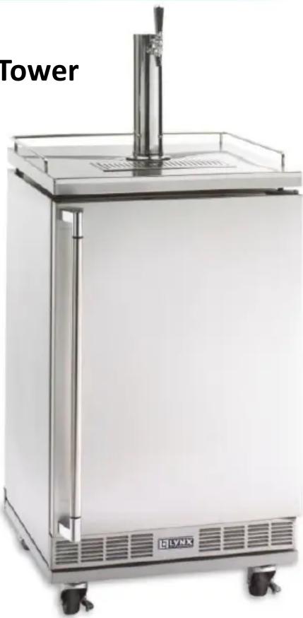
L24TWR Tower Kit - Mounng your kit directly to an island.
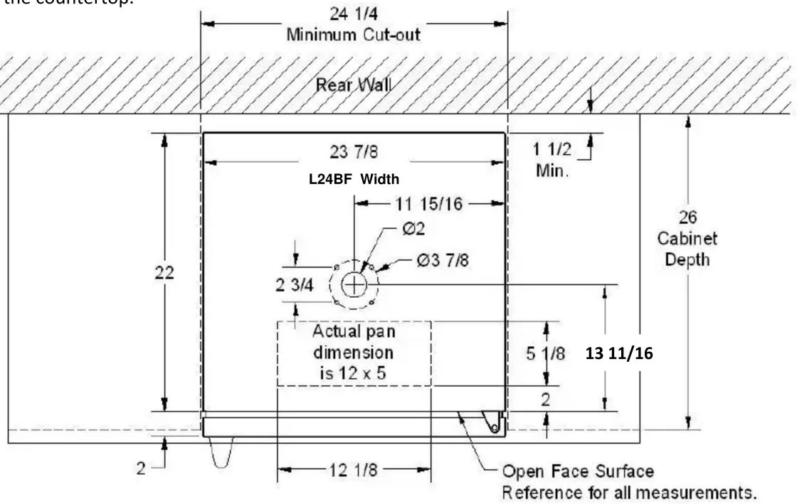
1) Determine the locaon of the refrigerator in the island installaon. It should be posioned nearly ush to the face surface of the island for easy access and alignment with the tower. The refrigerator cavity should be 35" high x 24-1/2" wide x 26" deep.
2) Posion the refrigerator in the island opening at the exact posion. Open the door and make a reference mark on the underside of the countertop at the face of the open refrigerator. This surface represents the best guide for locang the hole in the countertop. Each refrigerator door is custom set at the factory for the best seal. The face of the closed door varies slightly from unit to unit. DO NOT use the closed door surface as a reference.
3) Remove the refrigerator from the cabinet while drilling the holes for moung. Using the diagram at the boom of this page as a guide, mark the center of a 2" diameter hole and drill through the countertop for the beverage line.
4) Locate and drill the 4 moung holes to secure the keg tower.* Four #12 screws have been provided. A 1/4 " diameter hole is sucient for these bolts. If another securement method (i.e. lead anchors) are used, follow the manufacturers recommendaons.
5) A ush mount drip tray is provided as an opon. Refer to the diagram below and cut the opening required if this opon is to be installed.
6) Prepare the tower assembly for installaon. A 14 inch length of insulang foam has been provided to install inside the tower base. The installaon of this foam is crical to the proper operaon of the beverage tower kit. Failure to properly insulate the tower base could cause excessive foam and incorrect temperature control. Insert the foam around the beverage line and insert it into the beverage tower with about 2" protruding from the base.
7) Place the large at rubber gasket over the hole in the countertop.
8) Feed the beverage tube into the hole in the countertop
9) Align the gasket and secure the tower to the countertop with the 4 screws provided. From the underside insert the washers and nuts. Tighten the screws completely.
10) Remove the black plasc plug from the top center of the refrigerator. Keep in a safe place for future use.
11) Bring the beverage tube out to the front of the opening designed for the refrigerator. Begin to slide the L24BF refrigerator into the opening. Before the refrigerator is halfway into posion, feed the beverage tube through the hole in the top. Alternately slide the refrigerator back and draw the tube into the refrigerator to remove any kinks in the hose. When nished, the hose should align like the illustraon on the right.
12) Add the tap and handle with the wrench provided.
13) Insert the spill tray into the countertop.

* Before drilling mounng holes, posion the tower on the counter top to ensure proper tap alignment. Holes may be drilled out to 1/2 " to provide additional adjustment.
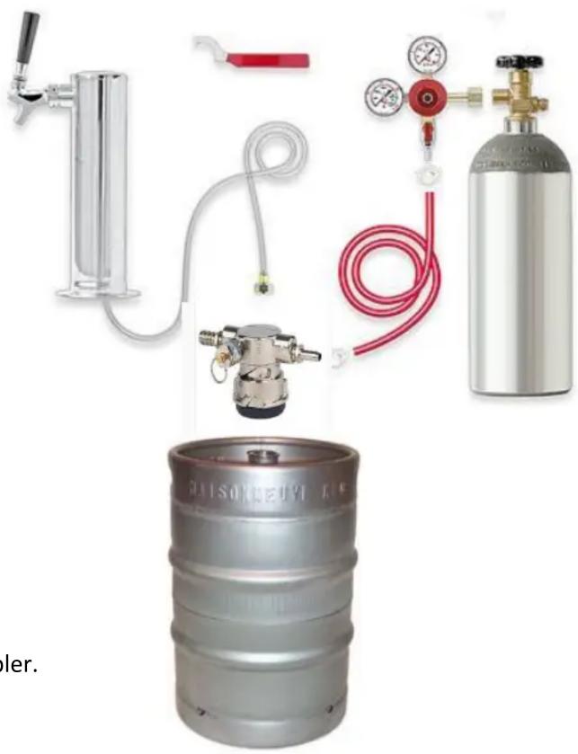
Connecng the Keg to the Beverage Tower.
1) Aach the clear hose from the beverage tower to the barbed ng with the hose clamp provided. Insert the rubber washer provided into the ng.
2) An elbow is included to provide additional space above the keg coupler. Secure the elbow to the top outlet of the keg coupler with a washer between. Aach the clear hose ng, with washer, to the elbow. Use a wrench to ghten the conncons.
3) The colored hose line is installed onto the side barbed ng of the keg coupler and the barbed ng below the CO2 regulator. Press the tube onto the ngs and secure with the two hose clamps.
Refer to the instrucons provided with the CO2 tank before aaching the tank to the regulator.
4) With the regulator and tank in the OFF posion, each the regulator securely to the CO2 tank with a wrench.
The Kit is Ready to Aach a Keg.
The Beverage Tower Kit is provided with a standard D Style coupler. This style is appropriate for most domesc beers. Additional styles are available from restaurant supply or beverage companies.

- Align lug locks on coupler with lug housing in top of keg; insert coupler.

- Turn coupler 1/4 turn clockwise; the coupler is now secured to keg.
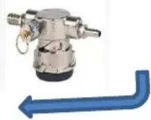
3. Push down on the coupler and give another 1/4 turn, to open beer and CO2 ports in keg. The keg is now tapped.
Operang the Beverage Tap:
1) Insert the CO2 canister in the rear le shelf inside the refrigerator.
2) Place the beer keg inside the refrigerator and arrange all hoses such that none are pinched.
3) Slowly open the main valve on the CO2 canister. Check for leaks.
4) Slowly open the regulator ball valve to pressurize the keg.
5) Toggle the tap handle on the tower to dispense a small amount of liquid. This will "charge the system".
6) Adjust the T-handle on the regulator to between 8 and 14 PSI. The pressure seng will vary for beer type and keg style. Refer to the troublesomeong guide and experimentaon to set the pressure accordingly.
7) Allow the system to rest for several hours before use. Temperature and pressure are critical to satisfactory results.

When not in use:
We recommend that the CO2 canister be shuto and the ball valve closed if the Beverage kit will not be used for an extended period of me. Keep the CO2 tank inside the refrigerator and all connexons intact. The CO2 tank should be replaced or relied when the CO2 Tank level indicator falls into the red indicator zone (below 300 PSI). Check with your beverage provider for local sources of CO2.
Storage:
For seasonal storage of the Beverage Kit we recommend that the CO2 tank be stored upright in a cool place. The Tower Base may be disconnected from the keg coupler and removed from the island installaon. To help prevent heat loss replace the black plasc cap into the top of the refrigerator (see page 2 step 1). The cap may be installed into the top or from the inside if more convenient. Seal all hoses and connectors in an air ght plasc bag to avoid dirt and insects during storage. We recommend that you obtain a cleaning kit and purge the uid lines seasonally. These may be obtained from your beverage supplier or on line.
Wild Beer Descripon
Beer, when drawn, is all foam, or too much foam and not enough liquid beer.
Causes
Beer drawn improperly
Creeping regulator
Applied pressure is set too high
Hot spots in line
Use of non-insulated beer line
Beer runs are too long for proper cooling
Tapped into a warm keg (Should be 34°-38° )
Cooler malfunconing
Kinks, dents, twists or other
obstrucons in line
Faucets in bad, dirty or worn condion
Flat Beer Descripon
Foamy head disappears quickly;
beer lacks usual zesul brewery fresh avor
Causes
Dirty glasses (not beer clean)
Sluggish regulator
Applied pressure is set too low
CO 2 is turned o at night
Contaminated air source
(associated with compressed air)
Moisture in air system
Beer too cold
Loose tap or vent connecons
Cloudy Beer Descripon
When beer in glass appears hazy, not clear
Causes
Frozen or nearly frozen beer
Old beer
Beer that has been unrefrigerated for
long periods of me
Dirty glass
Dirty faucet
Unrefrigerated foods placed on top of cold keg
Contaminated air source
False Head Descripon
Large soap-like bubbles, head dissolves very quickly
Causes
Applied pressure required does not correspond to
beer temperature
Small beer line into a large faucet shank
Beer lines warmer than beer in keg
Dry glasses
Improper pour
Unpalatable Beer Descripon
O-Taste
Causes
Dirty or old beer lines
Dirty faucet
Contaminated air source, or unltered
Unsanitary bar conditions
| Part No. | Descripon | Qty | |
| 1 | 32413 | Tower Assembly Single Tap, or Tower Assembly Double Tap 1 | |
| 33845 | |||
| 2 | 80411 | Beverage Center Deck Assembly | 1 |
| 3 | 32414 | Tubing, 7/8 OD, x 12 1 | |
| 4 | 32399 | Insulaon, Tower Armaex 1 | |
| 5 | L24TWB | Tower Base w/Leveling Feet 4 | |
| 6 | 33010 | Base, Spill Tray Insert 1 | |
| 7 | 33011 | Grate, Spill Tray Insert 1 | |
| 8 | 33031 | Faucet Wrench | 1 |
| Part No. | Descripon | Qty | |
| 9 | 32404 | CO2 Cylinder, 5 Pounds, Alum | 1 |
| 10 | 33029 | Regulator, Single Tap, CO2, or Regulator Double Tap, CO2 1 | |
| 33847 | |||
| 11 | 32403 | Keg Coupler, Domesc (Style D) | 1 |
| 12 | 33030 | Rubber Washer (Coupler) 2 | |
| 13 | 33027 | Hose, CO2 to Coupler 1 | |
| 14 | 33028 | Hose Clamps, CO2 | 2 |
| 15 | 33022 | Hose, Coupler to Tower 1 | |
| 16 | 33023 | Hose Clamps, Tower 1 |



- INSTALLATION, CARE AND USE OF YOUR LYNX BEVERAGE TOWER KITS
- LYNX BEVERAGE KITS
- MODEL L24TWS SINGLE TOWER AND L24TWD DOUBLE TOWER
- INTRODUCON
- WARNINGS
- BEVERAGE TOWER KIT COMPONENTS
- L24TWR TOWER KIT - MOUNNG YOUR KIT DIRECTLY TO AN ISLAND
- CONNECNG THE KEG TO THE BEVERAGE TOWER
- THE KIT IS READY TO AACH A KEG
- OPERANG THE BEVERAGE TAP
- WHEN NOT IN USE
- STORAGE
- WILD BEER DESCRIPON
- FLAT BEER DESCRIPON
- CLOUDY BEER DESCRIPON
- FALSE HEAD DESCRIPON
- UNPALATABLE BEER DESCRIPON
Brand : LYNX
Model : Professional L24TWS
Category : Wine cellar