
SM12 - Audio Mixer SOUNDCRAFT - Free user manual and instructions
Find the device manual for free SM12 SOUNDCRAFT in PDF.


| Product Type | Active Stage Monitor Speaker |
| Brand | Soundcraft |
| Model | SM12 |
| Speaker Size | 12 inches (woofer) |
| Amplifier Power | 500W RMS (Class D) |
| Frequency Response | 50 Hz - 20 kHz |
| Maximum SPL | 126 dB peak |
| Inputs | XLR, 1/4" TRS, RCA (line level) |
| Outputs | XLR mix out / link |
| Controls | Volume, EQ (bass/treble), ground lift |
| Enclosure Material | Plywood with black carpet finish |
| Dimensions (W x H x D) | 14.2 x 17.7 x 12.6 inches (360 x 450 x 320 mm) |
| Weight | 38.1 lb (17.3 kg) |
| Power Supply | 100-240 V AC, 50/60 Hz (IEC power cord) |
| Mounting Options | Floor monitor wedge, pole mount (socket) |
| Protection Features | Overcurrent, thermal, and limiter |
| Cleaning Instructions | Wipe with a dry cloth; avoid solvents |
| Included Accessories | Power cord, user manual |
| Certifications | CE, RoHS, FCC |
| Warranty | 2 years limited |
Frequently Asked Questions - SM12 SOUNDCRAFT
User questions about SM12 SOUNDCRAFT
0 question about this device. Answer the ones you know or ask your own.
Ask a new question about this device
Download the instructions for your Audio Mixer in PDF format for free! Find your manual SM12 - SOUNDCRAFT and take your electronic device back in hand. On this page are published all the documents necessary for the use of your device. SM12 by SOUNDCRAFT.
USER MANUAL SM12 SOUNDCRAFT
This equipment complies with the EMC Directive 89/336/EEC
For further details contact:
Harman International Industries Ltd, Cranborne House, Cranborne Road, Potters Bar, Herfordshire, EN6 3JN, U.K.
Tel: +44 (0) 1707 665000 Fax: +44 (0) 1707 660482
Soundcraft Electronics Ltd. 1994
All rights reserved
Parts of the design of this product may be protected by worldwide patents.
Part No. ZM0075-01
Information in this manual is subject to change without notice and does not represent a commitment on the part of the vendor. Soundcraft Electronics Ltd. shall not be liable for any loss or damage whatsoever arising from the use of information or any error contained in this manual.
No part of this manual may be reproduced, stored in a retrieval system, or transmitted, in any form or by any means, electronic, electrical, mechanical, optical, chemical, including photocopying and recording, for any purpose without the express written permission of Soundcraft Electronics Ltd.
It is recommended that all maintenance and service on the product should be carried out by Soundcraft Electronics Ltd. or its authorised agents. Soundcraft Electronics Ltd. cannot accept any liability whatsoever for any loss or damage caused by service, maintenance or repair by unauthorised personnel.
Soundcraft Electronics Ltd.
Cranborne House
Cranborne Industrial Estate
Cranborne Road
Potters Bar
Herts.
EN6 3JN
England
Tel: 0707 665000
Fax: 0707 660482
contents
Introduction 1
Introduction 2
Precautions and Safety Instructions 4
Installation 7
Connections 9
Module Block Diagrams 11
Input Module 17
Module Description, Operation and Specification 18
Output Module 23
Module Description, Operation and Specification 24
Master Module 27
Module Description, Operation and Specification 28
Appendices 35
Specification Notes 36
Performance Specifications 37
Configurations 38
Dimensions 39
Warranty 40
Glossary 41
Introduction
Introduction
The SM12 is a 12 bus dedicated monitor console to complement the Vienna and Europa FOH desks.
The key features of the SM12 are:
- 12 mono sends
- stereo send
- PRE/POST fade switching on each pair of sends and the stereo send
• 4 programmable mute groups
- 4 band sweep EQ
- 100mm linear faders on all inputs and outputs
- sophisticated solo system with autocancel, central global clear and switchable input priority.
• metering for all inputs and outputs
- external inputs for all group and stereo mix buses, with level control and listen facility
- balanced inserts on all outputs with bypass switching, and pre-insert solo facility
• balanced inserts on all inputs
Frame Sizes
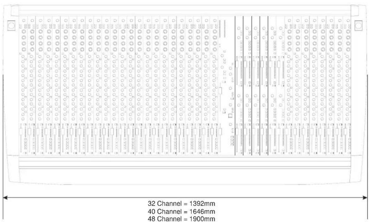
The SM12 is available in three frames sizes, 32, 40 and 48 channels. The consoles are configured, from left to right:
- inputs 1 - 24
- master
- groups 1 - 12 (6 modules)
- inputs 25 - 32 (32 channel)
- inputs 25 - 40 (40 channel)
- inputs 25 - 48 (48 channel)
Power Supplies
All frame sizes use the PSM300 PSU. Connection to the console is via a 10-way SRC connector below inputs 21-24. The console rear panel also carries a ground binding post.
Lamps
Two 4-pin XLR connectors for lamps are fitted to all frame sizes - one at either end of the console on the end trim. These are suitable for Littlite or similar 12V lamps taking up to 330mA each.
2 Introduction
Metering
Each input module has its own 8-segment bargraph meter and peak level indicator adjacent to the fader. The groups are metered by 16-segment bargraphs which are next to the faders on the output modules.
The two 16-segment bargraphs on the Master module meter either the PFL/AFL signals or the Stereo Mix signal depending on the wedge default internal setting.
Precautions and Safety Instructions
General Precautions
Avoid storing or using the mixing console in conditions of excessive heat or cold, or in positions where it is likely to be subject to vibration, dust or moisture. Do not use any liquids to clean the fascia of the unit: a soft dry brush is ideal. Use only water or ethyl alcohol to clean the trim and scribble strips. Other solvents may cause damage to paint or plastic parts.
Avoid using the console close to strong sources of electromagnetic radiation (e.g. video monitors, highpower electric cabling): this may cause degradation of the audio quality due to induced voltages in connecting leads and chassis. For the same reason, always site the power supply away from the unit.
Caution! In all cases, refer servicing to qualified personnel.
Handling and Transport
The console is supplied in a wooden crate. If it is necessary to move it any distance after installation it is recommended that this packing is used to protect it. Be sure to disconnect all cabling before moving. If the console is to be regularly moved we recommend that it is installed in a foamlined flightcase. At all times avoid applying excessive force to any knobs, switches or connectors.
Power Supplies & cables
The power supply unit incorporates automatic mains input voltage sensing and therefore no adjustment is needed to match local mains supplies.
Always use the power supply and cable supplied with the mixer: the use of alternative supplies may cause damage and voids the warranty; the extension of power cables may result in malfunction of the mixing console.
Warning!
Always switch the power supply off before connecting or disconnecting the mixer power cable, removing of installing modules, and servicing. In the event of an electrical storm, or large mains voltage fluctuations, immediately switch off the PSU and unplug from the mains.
Always ensure that you use the correct PSU for your mixer. The SM12 uses the PSM300 power supply.
Signal Levels
It is important to supply the correct input levels to the console, otherwise signal to noise ratio or distortion performance may be degraded, and in extreme cases, damage to the internal circuitry may result. Likewise, on all balanced inputs avoid sources with large commonmode DC, AC or RF voltages, as these will reduce the available signal range on the inputs. Note that 0dBu = 0.775V RMS.
The microphone inputs are designed for use with balanced low impedance (150 or 200 ohms) microphones.
Caution! DO NOT use unbalanced microphones or battery powered condenser microphones without isolating the +48V phantom power: degraded performance or damage to the microphone may result.
The sensitivity of the XLR inputs is variable from -2dBu to -70dBu and +10dBu to -20dBu in two ranges (for +4dBu at the Mix outputs). The maximum input level is +28dBu on the lower sensitivity range, and +18dBu on the higher range.
The Hi-Z inputs have a sensitivity variable between +10dBu and -20dBu. The maximum input level is +30dBu.
The main outputs of the console (stereo mix, groups, wedge and mix and group insert sends) are balanced at a nominal level of +4dBu, with a maximum output level of +26dBu.
The input insert sends are balanced at a nominal level of +4dBu, with a maximum output level of +26dBu.
All external inputs and mix and group insert returns have a nominal level of +4dBu, and a maximum input level of +26dBu except the AFL/PFL external inputs which are unbalanced at a nominal -2dBu, with a maximum input level of +20dBu.
Insert returns are balanced at a nominal level of +4dBu, and a maximum input level of +26dBu.
Installation
Installation
The SM12 is designed for reliability and high performance, and is built to the highest standards. Whilst great care has been taken to ensure that installations are made as troublefree as possible, care taken at this stage, followed by correct setting up will be rewarded by a long life and reliable operation.
Wiring Considerations
A For optimum performance it is essential for the earthing system to be clean and noise free, as all signals are referenced to this earth. A central point should be decided on for the main earth point, and all earths should be 'star-fed' from this point. It is recommended that an individual earth wire be run from each electrical outlet, back to the system star point to provide a safety earth reference for each piece of equipment.
B Install separate mains outlets for the audio equipment, and feed these independently from any other equipment.
C Avoid locating mains distribution boxes near audio equipment, especially tape recorders, which are very sensitive to electromagnetic fields.
D Where possible ensure that all audio cable screens and signal earths are connected to ground only at their source.
Power Supply
Always ensure that you use the correct PSU for your mixer. The SM12 uses the PSM300 power supply.
The power supply incorporates automatic mains input voltage sensing and therefore does not require adjustment for different local mains supplies.
Warning!
Before switching on your SM12 console, check that the fuse is of the correct rating and type. This is clearly marked on the case of the power supply. Do not replace the fuse with any other type, as this could become a safety hazard and will void the warranty.
Wiring conventions
The SM12 uses two different types of audio connector: 3-pin XLR and 1/4 " 3-pole jacks. These are used in several configurations, as shown below.

1/4" 'A' Gauge Stereo Jack Plug used as balanced input: Hi-Z inputs, insert returns, external inputs

1/4" 'A' Gauge Stereo Jack Plug used as ground compensated output: AFL/PFL outputs
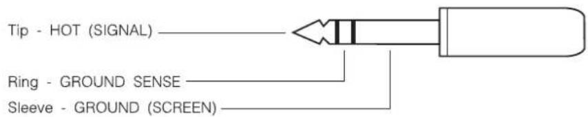
1/4" 'A' Gauge Stereo Jack Plug used as balanced output: Insert sends, oscillator

1/4" 'A' Gauge Stereo Jack Plug used as stereo output: Headphones

Module Block Diagrams
Input Module
![graph TD A["MIC I/P"] --> B["NORMALLING"] B --> C["HI-Z INPUT"] C --> D["RNGE"] D --> E["INPUT SENSITIVITY"] E --> F["PHASE INVERT"] F --> G["HI-PASS FILTER"] G --> H["4-BAND SWEEP EQ"] H --> I["EQ IN"] I --> J["PFL SWITCH"] J --> K["PEAK SIGNAL DETECT"] K --> L["PEAK DETECT"] L --> M["PFL BUS"] M -…](/content/2026/06/1349178/images/debe65cfec2a26d4e4bbf1789af6582faa7145f8db9388eea8b6062d20aab2b1.jpg)
Group Output Module
ONE GROUP SECTION ONLY SHOWN
![graph TD A["GROUP External INPUT BALANCED +400U NOMINAL"] --> B["SUMMING AMPLIFIER"] B --> C["FADER"] C --> D["+100B AT TOP"] D --> E["INSERT SEND"] E --> F["BALANCED +400U"] F --> G["INSERT RETURN"] G --> H["INSERT OUT"] H --> I["CUT SWITCH"] I --> J["TALBACK DIM WEDGE"] J --> K["DIM & ADD T/BACK"]…](/content/2026/06/1349178/images/dcfc4e202f81fb61f46388a4e80baf7ec448f64415092036de16db8503dfcf62.jpg)
Master Module
WEDGE & HEADPHONES
![graph TD A["EXTERNAL PFL INPUT"] --> B["Δ"] C["EXTERNAL AFL L IN"] --> D["Δ"] E["EXTERNAL AFL R IN"] --> F["Δ"] G["EXTERNAL PFL OUT"] --> H["Δ"] I["EXTERNAL AFL L OUT"] --> J["Δ"] K["EXTERNAL AFL R OUT"] --> L["Δ"] B --> M["Σ"] D --> N["Σ"] F --> O["Σ"] H --> P["θ"] J --> Q["θ"] L --> R["θ"] M --> S…](/content/2026/06/1349178/images/a1cd97f9c7dce073b24a96b2b477419b2e75980e36ae9af9cf94bdb8d96b95bd.jpg)
TALKBACK
![graph TD A["TALKBACK MICROPHONE"] --> B["Amplifier"] B --> C["TALKBACK SYSTEM"] C --> D["FOH ON T/BACK TO CRP"] D --> E["TALKBACK OUTPUT BALANCE + 400"] E --> F["SINEWAVE OSCILLATOR"] E --> G["PINK NOISE GENERATOR"] F --> H["OSC LEVEL"] G --> I["OSCILLATOR OUTPUT"] J["FCH TALKBACK INPUT"] --> K["EXT…](/content/2026/06/1349178/images/74ceedf3ef6ad1972ccd85d389224a3ff629d7c12f92bf9642cd7a18f1cdb736.jpg)
![graph TD A["MIX BUS LEFT"] --> B["SUMMING AMPLIFIER"] B --> C["FADER"] C --> D["INSERT SEND"] D --> E["INSERT RETURN"] E --> F["INSERT OUT"] F --> G["CUT SWITCH"] G --> H["DIM & ADD T/BACK"] H --> I["PHASE INVERT"] I --> J["MIX O/P TRANSFORMER OPTION"] J --> K["MIX LEFT OUTPUT BALANCE +400U"] L["LEF…](/content/2026/06/1349178/images/9308b778953af5a16441884bea1fba347c82bb201115559ac5227485e43408ff.jpg)
Input Module

Input Module
Input
1 The sensitivity of both the XLR and the HIGH IMPEDANCE (HI-Z jack) inputs is adjusted by the SENS control. Both inputs are electronically balanced.
2 The +48V switch, when depressed, applies +48V phantom power to the input XLR for powering condenser microphones.
3 The PHASE switch reverses the phase of the selected input.
4 The RNGE (Range) switch selects between an input range of -2dBu to -70dBu and +10dBu to -20dBu to allow line level signals to be used when the switch is pressed. The signal is still taken from the input XLR, unless a jack is inserted into the HI-Z input socket, when the signal from that is used instead.
Note that when the RNGE switch is released the Hi-Z input socket cannot be used, and that phantom power is not applied to the Hi-Z jack.
5 Pressing thFILTER switch activates a pre-insert high-pass filter section.
Frequency Response Curves of the High-Pass Filter

Equaliser
This section is a four band, peaking sweep EQ.
6 The HF section has a maximum cut or boost of 15dB and the frequency is variable between 1kHz and 20kHz, with a Q of 1.3.
The HMF (High Mid) section has a maximum cut or boost of 15dB and the frequency is variable between 450Hz and 12kHz, with a Q of 1.3.
The LMF (Low Mid) section has a maximum cut or boost of 15dB and the frequency is variable between 60Hz and 1k5Hz, with a Q of 1.3.
The LF section has a maximum cut or boost of 15dB and the frequency is variable between 12Hz and 350Hz, with a Q of 1.3.
7 The EQ section is switched in when the EQ switch is depressed.
The Frequency Response Curves of the Equaliser

LF EQ

HF EQ
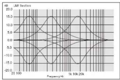
LMF EQ
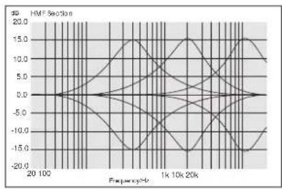
HMF EQ
Groups
8 The input signal is sent to the group 1 - 12 buses via individual Level Controls. These have unity gain when fully clockwise.
The group sends are switched pre- or post-fader in pairs by the PRE buttons. The pre-fade signal may be sourced either pre-mute or post-mute, and selection is done in three blocks of four sends, using push-on jumpers.
The factory default is post-mute.
Stereo Mix
9 The post-fader signal is sent to the stereo mix bus via the L/R (level) control. The mix bus send may be set pre- or post-fade by the PRE switch. The pre-fade signal may be sourced pre- or post-mute using push-on jumpers.
The factory default is post-mute.
10 The PAN control allows the channel signal to be positioned within the stereo mix. Rotation fully anticlockwise sends the signal to the Left bus, rotation clockwise sends the signal to the Right bus. There is a 4.5dB drop in the centre position.

11 The signal in the module is turned on and off by the CUT switch and by the MUTE buses (see below).
An integral red LED in the CUT switch indicates when the signal is cut.
12 The Post-fader signal level is controlled by a 100mm FADER before being fed to the Groups and the Stereo Mix buses.
13 The redPEAK LED illuminates when the signal level is within 6dB of clipping at the output of the input amp (after the high-pass filter), the output of the EQ or the post-fader amplifier.
A three colour, 8-segment bargraph meter beside the fader meters the signal directly after the input amplifier. The meter has a peak-reading characteristic.
Muting System
14 Each Input module is assigned to the four mute buses using the MUTE 1 - 4 buttons. The module is assigned to its respective mute bus when each switch is pressed.
Pressing the SAFE switch isolates the module from the effect of the Master Mutes, and reinstates the previous mute selection when released.
When the module is muted by any of the mute buses, the LED in the CUT switch illuminates.
PFL
15 The electronically latch PFL switch feeds the pre-fade, pre-mute signal to the PFL bus, which in turn feeds the engineer's wedge speakers and phones outputs via the Master section. An integral amber LED indicates when the PFL switch is active.
Insert Point
The module insert point uses a balanced send and a balanced return, at a nominal level of +4dBu. The signal is accessible via separate 1/4" jacks on the rear connector panel.
The insert point may be set to pre- or post-EQ by push-on jumpers. The factory default is pre-EQ.
Jumper Options (RH PCB)
Function Options Default
Insert point pre-EQ
J1, J2, J3 jumpers IN for pre-EQ
J4, J5, J6 jumpers IN for post-EQ
Group 1-4 Pre-fade signal post-mute
J11 jumper IN for pre-mute
J12 jumper IN for post-mute
Note: only one of the above two jumpers to be fitted at any one time.
Group 5-8 Pre-fade signal post-mute
J9 jumper IN for pre-mute
J10 jumper IN for post-mute
Note: only one of the above two jumpers to be fitted at any one time.
Group 9-12 Pre-fade signal post-mute
J7 jumper IN for pre-mute
J8 jumper IN for post-mute
Note: only one of the above two jumpers to be fitted at any one time.
Mix L-R Pre-fade signal post-mute
J13 jumper IN for pre-mute
J14 jumper IN for post-mute
Note: only one of the above two jumpers to be fitted at any one time.
Input and Output Levels
XLR INPUT (electronically balanced)
Sensitivity -2dBu to -70dBu (hi sens.),
+10dBu to 20dBu (low sens.)
Maximum Input Level +28dBu (low sens.), +18dBu (hi sens.)
Input Impedance 2KΩ
HI-Z INPUT (electronically balanced)
Sensitivity +10dBu to -20dBu
Maximum i/p level +30dBu
Input Impedance >10KΩ balanced
INSERT SEND
Nominal Level +4dBu
Maximum Output Level +26dBu into 2kΩ
Output Impedance <75Ω
INSERT RETURN (electronically balanced)
Sensitivity +4dBu
Maximum I/P Level +26dBu
Input Impedance >10KΩ balanced
Rear Connectors

The connections to the rear connector panel are as follows:
INPUT (3 pin female XLR)
Pin 1 Ground
Pin 2 Signal (Hot)
Pin 3 Signal (Cold)
HI-Z INPUT, INSERT RETURN (1/4" 3-pole Jack)
Tip Signal (Hot)
Ring Signal (Cold)
Sleeve Ground
INSERT SEND, (1/4" 3-pole Jack)
Tip Signal (Hot)
Ring Signal (Cold)
Sleeve Ground
Group Output Module

Group Output Module
External Input
An external input, from a jack socket on the rear panel, may be added to the group bus. The input is balanced with a sensitivity of +4dBu.
1 The EXT IN control adjusts the level of the external signal to the group, it provides a maximum 10dB gain when it is fully clockwise.
2 The latchingON switch activates the external input when pressed.
3 The momentary LSTN (Listen) switch provides a pre-level control, pre-ON solo to the 'phones or wedge output. LISTEN is not affected by the AUTO CANCEL or SOLO CLEAR functions, and overrides any output AFLs if INPUT PRIORITY is active. Pressing LSTN will not cancel other solos.
Six output modules are fitted in each console. The output module contains two group output sections, stacked one above the other. The lower sections control groups 1 - 6, while the upper sections control groups 7 - 12. The two sections have identical facilities.
Level Control
The group summing amp is assigned to one of the twelve group buses using internal push-on jumpers.
4 The 100mmFADER controls the level of the signal from the summing amplifier, which is fed to the insert send and ultimately the Group Output, with 10dB of gain at maximum.
Insert Point
5 The insert point is post-fade, and uses an electronically balanced send and return at a nominal level of +4dBu. The insert SEND and RETURN are on separate 1/4" jacks on the rear connector panel. The insert point may be bypassed using the INSERT OUT switch.
Output Switching
6 The PHASE switch reverses the phase of the group output. The group output itself is electronically balanced at +4dBu, on a male XLR on the rear connector.
7, 8 The L and R switches route the group signal to the left and right stereo mix buses respectively. This feature allows subgroups to be created, if the console is used in a FOH application.
9 The CUT switch mutes the signal to the group output and stereo mix bus (if selected). The switch has an integral red LED which indicates when the signal is cut.
Talkback
10 The momentary TB switch feeds the signal from the TALKBACK MICROPHONE to the group output; it is independent of the Fader position and the CUT switch. The existing group output is dimmed by 6db, and the engineer's wedge speaker is dimmed by 20dB while the TB switch is active.
Talkback may also be routed to all the group buses simultaneously by the INT talkback function on the master module; in this case the group CUT and fader will affect the talkback level.
Metering
11 The group output level is metered by an integral peak-reading 16-segment LED bargraph which is situated next to the Fader; the meter is calibrated for 0 at +4dBu output. An internal jumper allows the meter response to be set to average-reading instead of peak-reading.
Solo
12 The electronically latching AFL switch, which has an integral amber LED, feeds the post-fade, post-insert group signal to the engineer's wedge speakers and phones output; however, if INPUT PRIORITY (see the Master Module) is enabled then any active input PFLs will replace the AFL signal, and the group will not be heard until the inputs are un-PFLed. If solo AUTO CANCEL (see the Master Module) is selected, then the AFL will cancel any other active PFLs or AFLs. The AFL may also be cleared with the Master Module's SOLO CLEAR function.
13 The PRE INSERT switch moves the AFL signal before the insert point.
14 The AFL TRIM control gives +/-10dB of level adjustment.
Jumper Options
Function Options Default
Lower group bus programming *
J101 - J106 Group 1 - 6 According to
Module Position
Upper group bus programming *
J201 - J206 Group 7 - 12 According to
Module Position
Lower Meter Response
J109 Peak or Average Peak
Upper Meter Response
J209
Peak
or
Average
* only to be changed if the module is moved to a different position within the group section.
Input and Output Levels
Insert Sends, Group Outputs (electronically balanced)
Nominal level +4dBu
Maximum output level +26dBu into 600Ω
Output impedance <75Ω
Insert Returns, External Inputs (electronically balanced)
Sensitivity
+4dBu
Maximum i/p level +26dBu
Input impedance >10KΩ balanced
Rear Connectors

External Inputs (1/4" 3pole Jack)
Tip Signal (Hot)
Ring
Signal
(Cold)
Sleeve
Ground
Insert Return (1/4" 3pole Jack)
Tip Signal (Hot)
Ring
Signal
(Cold)
Sleeve
Ground
Insert Send, (1/4" 3pole Jack)
Tip Signal (Hot)
Ring
Signal
(Cold)
Sleeve
Ground
Group Outputs, (3 pin male XLR)
Pin 1 Ground
Pin 2 Signal (Hot)
Pin 3 Signal (Cold)

Master Module
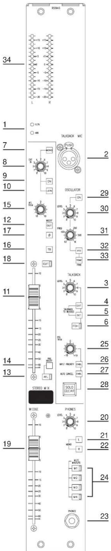
The master module contains the stereo mix or sidefill output, the operator's headphones and wedge speaker outputs, a noise or sine wave test oscillator, the solo mode controls and master solo clear function, and internal/external talkback functions.
PSU Status Indicators
1 The two PSU Status Indicator LEDs (red) show that the +/-17V and +48V PSU rails are working.
Talkback
The talkback system allows communication by the operator to the group and mix outputs, and to and from the front of house (FOH) console.
2 The TALKBACK MIC XLR accepts a local talkback microphone or gooseneck.
3 The TALKBACKLEVEL control adjusts the sensitivity of the talkback mic input. The sensitivity of the mic input is variable between -20dBu and -50dBu.
4 The TALKBACK TO BUSSES EXT button sends the T/BACK IN signal to the group and mix buses when FOH talkback is active to allow the front-of-house engineer to talk to the performers via the monitor outputs.
5 The TALKBACK/OSC TO BUSSES INT button routes the talkback signal from the mic to all group busses and the stereo mix bus simultaneously. The oscillator is also routed via this switch if it is turned 'on'.
6 The momentary action FOH button initiates talkback to the front of house console using a Soundcraft proprietary system. The talkback mic signal is switched to the FOH OUT XLR, with a +15v DC common-mode voltage to signal the FOH console that talkback is occurring. The signal present on the FOH IN XLR is fed to the 'phones, dimming the existing signal by 15dB. The wedge is dimmed by 20dB. An internal jumper disables the common-mode DC voltage, to allow use with non-Soundcraft desks.
If a 15v common-mode voltage is detected on the FOH IN XLR, indicating talkback from the front-of-house console, then the FOH IN signal is switched to the 'phones output, dimming the existing signal by 15dB, and dimming wedge output by 20dB. The FOH switch also lights.
The signal from the talkback mic. may be routed to the group or mix outputs individually by pressing the TB button on each output; this also dims the wedge output by 20dB.
External Input
7 The MONO switch sums the external signal to mono before it is fed to the stereo mix.
8 A stereo external input, from XLRs on the rear connector panel, may be added to the mix buses. The inputs are balanced with a sensitivity of +4dBu. The EXT IN control adjusts the level of the external signals, with 10dB of gain fully clockwise.
9 The latchingON switch activates the external input.
10 The momentarLSTN (listen) switch provides a mono pre-fade, pre-ON solo to the 'phones or wedge output. LISTEN is not affected by the AUTO CANCEL or SOLO CLEAR functions, and overrides any output AFLs if INPUT PRIORITY is active. Pressing LSTN does not cancel other solos.
Stereo Mix
The stereo mix path is similar in function to the group outputs, but provides a stereo output.
11 The 100mm stereo mix FADER controls the level of the signal from the summing amplifiers. This stereo signal is fed to the left and right insert sends and ultimately to the left and right outputs, with 10dB of gain at the maximum.
Insert Point
The inserts are postfade, using electronically balanced sends and returns at a nominal level of +4dBu. The insert SENDs and RETURNS are on separate 1/4" jacks on the rear connector panel.
12 Both left and right inserts may be bypassed using the INSERT OUT switch. Note that the sends are always active.
AFL
13 The electronically latching AFL switch, which has an integral amber LED, feeds the stereo post-fade, post-insert signal to the engineer's wedge speakers and phones output.
14 The PRE INSERT switch moves the AFL signal before the insert point.
15 The AFL TRIM pot gives +/-10dB of level adjustment.
Talkback
16 The momentary TB switch activates the signal from the TALKBACK MICROPHONE and feeds it to the stereo mix output; it is independent of the Fader position and the CUT switch. The stereo output is dimmed by 6db, and the engineer's wedge speaker is dimmed by 20dB while the TB switch is active.

Talkback may also be routed to all the group buses and the stereo mix bus simultaneously by the INT talkback function on this module; in this case the Group/Stereo CUT and fader will affect the talkback level.
Output Switching
17 The PHASE switch reverses the phase of both left and right outputs. The outputs themselves are electronically balanced at +4dBu, on male XLRs on the rear panel.
18 The CUT switch mutes the signal to the left and right outputs. The switch has an integral red LED which indicates when the signal is cut.
Wedge and Headphones Outputs
The wedge (operator's speaker) and headphones outputs share a common signal source: when no PFL, AFL or LISTENs are active, then the source is either the external PFL and AFL inputs, or the stereo mix signal, according to the position of an internal jumper. The purpose of this jumper is to allow the wedge output to be either quiet in the absence of any solo signals (preferred in monitor mixing applications) or to monitor the stereo output in the absence of solo signals (preferred for FOH mixing applications).
When a solo is active the signal is the console AFL or PFL signal, summed with the external PFL and AFL signals.
19 The stereo wedge output level is controlled by the 100mm wedge Fader and is balanced at +4dBu on XLRs.
20 The headphones output level is adjusted by the PHONES control; the output is available on a 1/4" 3-pole jack on the front panel.
21, 22 When the switch is depressed, the Left signal is fed to both Left & Right Wedge outputs. Similarly, when the R switch is depressed, the Right signal is fed to both Wedge outputs. When the L and R buttons are both depressed, a MONO mix of the Left and Right signals is fed to both Wedge outputs.
23 The HEADPHONES jack. Output level is control by the PHONES control (see 20 above)
Mute Masters
24 The four, latching, Mute Master buttons M1 - 4, which each have an integral red LED, control the four mute buses. Any inputs assigned to a mute bus will be cut by the appropriate mute master, except those on which the SAFE switch has been pressed.
Using the Solo System
A solo system of pre-fade listen (inputs) and post-fade listen (outputs) feeds the operator's wedge/ phones outputs.
Normally, all active AFL, PFL and LISTEN signals are summed together and fed to the wedge or phones outputs.
25 The PFL TRIM control gives +/-10dB of level trim for PFL/LISTEN signals.
26 When INPUT PRIORITY is selected by the ENBL switch, an active PFL or LISTEN will replace any AFL signals, which will be audible only when all the PFL/LISTENs are released.
27 When AUTO CANCEL is activated by the ENBL button, any AFL or PFL will cancel any currently active solo, so only one AFL or PFL can be active at once.
When INPUT PRIORITY and AUTO CANCEL are both pressed, the effect will be similar to '26' above, but also with autocancelling between groups of outputs and groups of inputs.
LISTEN buttons are not affected.
28 The SOLO CLEAR button lights when any AFL, PFL or LISTEN is active. Pressing it will clear a PFL or AFL, but not a LISTEN.
The logic control modes are summarised below:
| Mode | Autocancel button | Input priority button | Description |
| ‘Normal’ | 0 (=off) | 0 | All output and input solos are additive |
| ‘Autocancel’ | X (=on) | 0 | All solos Autocancel, no distinction between output and input |
| ‘Input priority’ | 0 | X | If an output is left on solo, soloing an input will temporarily override the output but will return to it when the input is unsoloed |
| ‘Input/output Autocancel with I/P priority’ | X | X | Combination of the last two - as input priority, but also with Autocancelling between groups of outputs and groups of inputs |
External Solo Signals
The PFL, AFL Left and AFL Right external inputs, from 1/4" jack sockets on the rear panel allow signals from another console to be added to the PFL and AFL buses. The external PFL level is trimmed by the PFL TRIM pot. When no solos are active on the console, both PFL and AFL left and right external signals are monitored by the 'phones and wedge (if selected by internal jumper, see below). When INPUT PRIORITY is not active, the external signals are mixed with any current internal PFL, AFL or LISTEN signals; if INPUT PRIORITY is enabled and a PFL/LISTEN is active then the external AFL input is cut.
Internal jumpers allow the signal fed to the 'phones/wedge when no solos are active to be changed from the external PFL/AFL signals (as described above) to the stereo mix postfade signal. This will be replaced by any active solo signal. To monitor the external PFL/AFL inputs in this case, a solo on the console must be pressed. The purpose of these jumpers is to allow the wedge output to be either quiet in the absence of any solo signals (preferred in monitor mixing applications) or to monitor the stereo output in the absence of solo signals (preferred for FOH mixing applications).
PFL and AFL Outputs
The PFL, AFL left and AFL right output signals are available on 1/4" jack sockets on the rear connector panel, ground compensated at -2dBu. These are for use when linking the console (as a client), or for additional monitoring.
Oscillator
29 The oscillator, activated by the ON switch, produces pink noise or tone.
30 The oscillator signal is fed to the oscillator output, balanced at a nominal level of +4dBu, on a 1/4" jack socket on the rear connector panel. The oscillator can also be fed to the group and stereo mix busses by pressing the TALKBACK/OSC TO BUSSES 'INT' switch (see 5 on page 28). The LEVEL control adjusts the level from off to 10dB above nominal.
31 When tone is selected (see 33 below) the oscillator tone frequency is variable between 63Hz and 1kHz: it is adjusted by the FREQ control.
32 The X10 button changes the frequency range to 630Hz - 10kHz.
33 Pressing thTONE button switches the signal from pink noise to sine wave.
Metering
34 Two 16-segment bargraph meters at the top of the module monitor the level of the stereo mix or the external AFL/PFL signal, depending on the wedge default jumper setting, or the current solo signal when a solo is active; the AFL signal from the stereo mix is displayed in stereo while mono AFLs (from the groups) and PFL/LISTEN signals (taken after the PFL trim pot) are fed to both left and right meters.
The meter response may be selected as peak-reading or average by changing the position of internal jumpers.
Jumper Options
Function Options Default
Phones/Wedge Signal
(RH board SC3425)
JMP1 jumper out for Stereo Mix Ext. PFL/AFL
(FOH applications)
jumper in for Ext. AFL/PFL
(Monitor applications)
FOH Out DC Voltage
(RH board SC3425)
JMP2 Enabled or disabled Enabled (jumper out)
Bargraph Response
(LH board SC3426X)
J301
(small meter board SC3426Y)
J401 ** peak or average peak
** The small meter board must be removed to change this jumper
Input and Output Levels
INSERT SENDS, MIX, WEDGE AND FOH TALKBACK OUTPUTS (Electronically Balanced)
nominal level +4dBu maximum output level +26dBu into 600Ω output impedance <75Ω
OSCILLATOR OUTPUT (Electronically Balanced)
nominal level +4dBu maximum output level +14dBu into 600Ω output impedance <75Ω
PFL, AFL LEFT AND RIGHT OUTPUTS (Ground Compensated)
nominal level -2dBu maximum output level +20dBu into 2kΩ output impedance <75Ω
INSERT RETURNS, GROUP & STEREO EXTERNAL AND FOH TALKBACK INPUTS (Electronically Balanced)
sensitivity +4dBu maximum i/p level +26dBu input impedance >10KΩ balanced
PFL EXTERNAL INPUTS (Electronically Balanced)
sensitivity -2dBu maximum i/p level +20dBu input impedance >10kΩ balanced
TALKBACK MICROPHONE INPUT (Electronically Balanced)
sensitivity -20dBu to -50dBu maximum i/p level 0dBu input impedance 2kΩ
PHONES OUTPUT (Unbalanced)
nominal level +4dBu maximum output level +20dBu into 600Ω 0dBu into 8Ω output impedance 50Ω
Rear Connectors
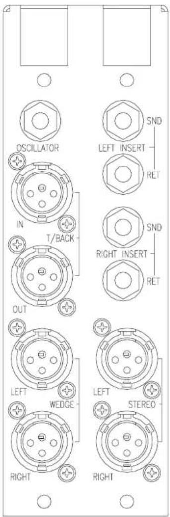
External (FOH) Talkback In and Talkback Mic (3-pin female XLR)
Pin 1 Ground
Pin 2 Signal Hot
Pin 3 Signal Cold
Insert Returns, Ext. Inputs (1/4" 3-pole Jack)
Tip Signal Hot
Ring Signal Cold
Sleeve Ground
Insert Sends, Oscillator Output (1/4" 3-pole Jack)
Tip Signal Hot
Ring Signal Cold
Sleeve Ground
PFL, AFL Left and Right Outputs (1/4" 3-pole Jack)
Tip Signal
Ring Ground Sense
Sleeve Ground
Mix, Wedge and Talkback Outputs (3-pin male XLR)
Pin 1 Ground
Pin 2 Signal Hot
Pin 3 Signal Cold
Phones Output (1/4" 3-pole Jack)
Tip Left Signal
Ring Right Signal
Sleeve Ground

Appendices
SPECIFICATION NOTES AND CONDITIONS
A The Console has a nominal output level of +4dBu: all input sensitivities are relative to this, i.e., with line input gain set to '0', an input of 0dBu will give an output of +4dBu at any group or mix output, and a sensitivity of +4dBu gives unity gain from input to output.
B Noise measurements are taken with 22Hz-22kHz bandwidth, rms-reading response.
C Distortion measurements are made with an input of +20dBu (line inputs at unity gain) giving an output of +20dBu. The analyser reads THD+N with an average response over a 10Hz-30kHz bandwidth.
D Frequency response and EQ measurements are made with an input of 0dBu to line inputs at unity gain: outputs are quoted relative to 0dBu.
E Crosstalk and rejection measurements are made with an input level of +20dBu (line inputs at unity gain) giving an output of +20dBu on the active signal path. The ratio quoted is relative to +20dBu output.
F Gain tolerance is +/- 1.5dB or 10% of the indicated value, whichever is the greater.
G Group Noise: noise measured at the group output with faders at unity, and channel send pots down.
H Mix Noise: noise measured at the stereo mix output with faders at unity, and channel sends off.
Measured on a 40 channel console.
Frequency response
Line input to any output: 20Hz - 20kHz, +0/-0.5dB
Crosstalk (measured at 1kHz)
Channel CUT isolation >100dB
Channel Fader isolation >95dB
Channel Send Pot isolation >75dB
Group Fader isolation >95dB
Group CUT isolation >95dB
Noise (22Hz-22kHz bw, unweighted rms)
XLR input at maximum sensitivity <-127.5dBu
(200ohm source)
Group Output noise <-82dBu
(Group faders at unity, channel sends down)
Mix output noise <-84dBu
Mix faders at unity, channel sends off)
Distortion (THD + Noise, measured at 20dBu, 30kHz bw)
Line In to Group or Mix out <0.005% @ 1kHz
<0.025 @ 10kHz

Console Rear View
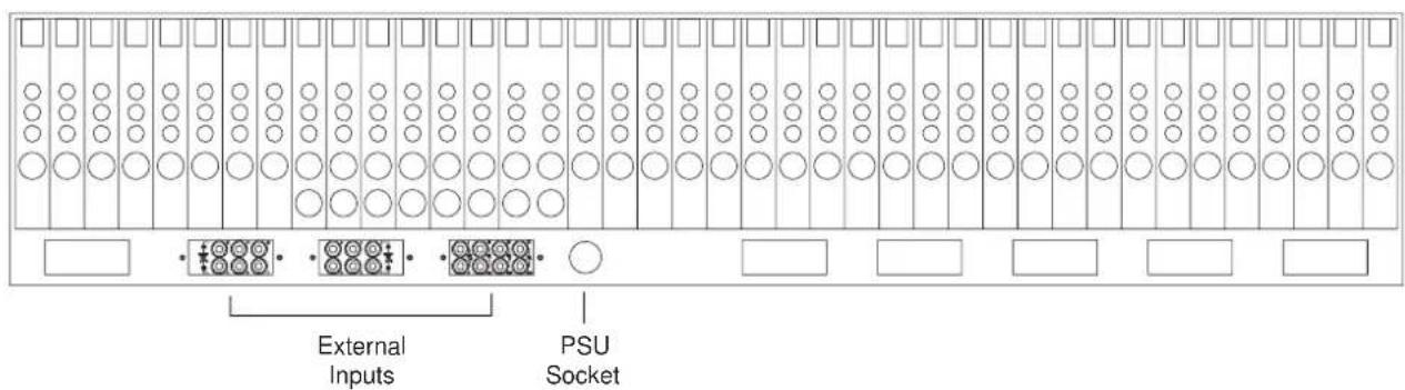
SM12 Outline Dimensions
All dimensions are in millimetres

1 Soundcraft means Soundcraft Electronics Ltd.
End User means the person who first puts the equipment into regular operation.
Dealer means the person other than Soundcraft (if any) from whom the End User purchased the Equipment, provided such a person is authorised for this purpose by Soundcraft or its accredited Distributor.
Equipment means the equipment supplied with this manual.
2 If within the period of twelve months from the date of delivery of the Equipment to the End User it shall prove defective by reason only of faulty materials and/or workmanship to such an extent that the effectiveness and/or usability thereof is materially affected the Equipment or the defective component should be returned to the Dealer or to Soundcraft and subject to the following conditions the Dealer or Soundcraft will repair or replace the defective components. Any components replaced will become the property of Soundcraft.
3 Any Equipment or component returned will be at the risk of the End User whilst in transit (both to and from the Dealer or Soundcraft) and postage must be prepaid.
4 This warranty shall only be available if:
a) the Equipment has been properly installed in accordance with instructions contained in Soundcraft's manual; and
b) the End User has notified Soundcraft or the Dealer within 14 days of the defect appearing; and
c) no persons other than authorised representatives of Soundcraft or the Dealer have effected any replacement of parts maintenance adjustments or repairs to the Equipment; and
d) the End User has used the Equipment only for such purposes as Soundcraft recommends, with only such operating supplies as meet Soundcraft's specifications and otherwise in all respects in accordance Soundcraft's recommendations.
5 Defects arising as a result of the following are not covered by this Warranty: faulty or negligent handling, chemical or electro-chemical or electrical influences, accidental damage, Acts of God, neglect, deficiency in electrical power, air-conditioning or humidity control.
-
The benefit of this Warranty may not be assigned by the End User.
-
End Users who are consumers should note their rights under this Warranty are in addition to and do not affect any other rights to which they may be entitled against the seller of the Equipment.
Glossary
| Auxiliary Send | an output from the console comprising a mix of signals from channels and groups derived independently of themain stereo group mixes. Typically the feeds to the mix are implemented on rotary level controls. |
| Balance the relative levels of the left and right channels of a stereo signal. | |
| Clipping | the onset of severe distortion in the signal path, usually caused by the peak signal voltage being limited by the circuit's power supply voltage. |
| CR (Control Room) Monitors | loudspeakers used by the operator (engineer) in the control room to listen to the mix. |
| dB (decibel) a ratio of two voltages or signal levels, expressed by the equation dB=20Log10(V1/V2). Adding the suffix 'u' denotes the ratio is relative to 0.775V RMS. | |
| DI(Direct Injection) | the practice of connecting an electronic musical instrument directly to the input of the mixing console, rather than to an amplifier and loudspeaker which is covered by a microphone feeding the console. |
| Equaliser | a device that allows the boosting or cutting of selected bands of frequencies in the signal path. |
| Foldback | a feed sent back to the artistes via loudspeakers or headphones to enable them to monitor the sounds they are producing. |
| Frequency Response the variation in gain of a device with frequency. | |
| (sub) Group an output into which a group of signals can be mixed. | |
| Headroom the available signal range above the nominal level before clipping occurs. | |
| Highpass Filter a filter that rejects low frequencies. | |
| Line Level Signals | at a nominal level of -10dBV to +6dBu, coming from a low impedance source. |
| Noise Gate | an electronic switch which only passes signals exceeding a set threshold level. |
| Pan (pot) abbreviation of 'panorama': controls levels sent to left and right outputs. | |
| Patchbay | a connection panel providing access to most input/output signals on the console, allowing the operator to redirect or rearrange internal and external connections using flexible patch cords. |
| Peaking | an equaliser response curve affecting only a band of frequencies i.e. based on a bandpass response. |
| PFL (Pre-fade Listen) | a function that allows the operator to monitor the pre-fade signal in a channel independently of the main mix. |
| Rolloff | a fall in gain at the extremes of the frequency response. |
| Shelving | an equaliser response affecting all frequencies above or below the break frequency i.e. a highpass or lowpass derived response. |
| Spill | acoustic interference from other sources. |
| Talkback | the operator speaking to the artistes or to tape via the auxiliary or group outputs. |
- CONTENTS
- INTRODUCTION 1
- INSTALLATION 7
- MODULE BLOCK DIAGRAMS 11
- INPUT MODULE 17
- OUTPUT MODULE 23
- MASTER MODULE 27
- APPENDICES 35
- INTRODUCTION
- 2 INTRODUCTION
- METERING
- PRECAUTIONS AND SAFETY INSTRUCTIONS
- GENERAL PRECAUTIONS
- CAUTION! IN ALL CASES, REFER SERVICING TO QUALIFIED PERSONNEL
- HANDLING AND TRANSPORT
- POWER SUPPLIES & CABLES
- WARNING
- SIGNAL LEVELS
- CAUTION! DO NOT USE UNBALANCED MICROPHONES OR BATTERY POWERED CONDENSER MICROPHONES WITHOUT ISOLATING THE +48V PHANTOM POWER: DEGRADED PERFORMANCE OR DAMAGE TO THE MICROPHONE MAY RESULT
- INSTALLATION
- WIRING CONSIDERATIONS
- POWER SUPPLY
- WIRING CONVENTIONS
- MODULE BLOCK DIAGRAMS
- MASTER MODULE
- INPUT MODULE
- INPUT
- EQUALISER
- THE FREQUENCY RESPONSE CURVES OF THE EQUALISER
- GROUPS
- STEREO MIX
- MUTING SYSTEM
- PFL
- INSERT POINT
- JUMPER OPTIONS (RH PCB)
- FUNCTION OPTIONS DEFAULT
- INSERT POINT PRE-EQ
- GROUP 1-4 PRE-FADE SIGNAL POST-MUTE
- GROUP 5-8 PRE-FADE SIGNAL POST-MUTE
- GROUP 9-12 PRE-FADE SIGNAL POST-MUTE
- MIX L-R PRE-FADE SIGNAL POST-MUTE
- INPUT AND OUTPUT LEVELS
- XLR INPUT (ELECTRONICALLY BALANCED)
- HI-Z INPUT (ELECTRONICALLY BALANCED)
- INSERT SEND
- INSERT RETURN (ELECTRONICALLY BALANCED)
- REAR CONNECTORS
- INPUT (3 PIN FEMALE XLR)
- HI-Z INPUT, INSERT RETURN (1/4" 3-POLE JACK)
- INSERT SEND, (1/4" 3-POLE JACK)
- GROUP OUTPUT MODULE
- EXTERNAL INPUT
- LEVEL CONTROL
- OUTPUT SWITCHING
- TALKBACK
- SOLO
- JUMPER OPTIONS
- INSERT SENDS, GROUP OUTPUTS (ELECTRONICALLY BALANCED)
- INSERT RETURNS, EXTERNAL INPUTS (ELECTRONICALLY BALANCED)
- EXTERNAL INPUTS (1/4" 3POLE JACK)
- INSERT RETURN (1/4" 3POLE JACK)
- INSERT SEND, (1/4" 3POLE JACK)
- GROUP OUTPUTS, (3 PIN MALE XLR)
- PSU STATUS INDICATORS
- AFL
- WEDGE AND HEADPHONES OUTPUTS
- MUTE MASTERS
- USING THE SOLO SYSTEM
- EXTERNAL SOLO SIGNALS
- PFL AND AFL OUTPUTS
- OSCILLATOR
- PHONES/WEDGE SIGNAL
- FOH OUT DC VOLTAGE
- BARGRAPH RESPONSE
- INSERT SENDS, MIX, WEDGE AND FOH TALKBACK OUTPUTS (ELECTRONICALLY BALANCED)
- OSCILLATOR OUTPUT (ELECTRONICALLY BALANCED)
- PFL, AFL LEFT AND RIGHT OUTPUTS (GROUND COMPENSATED)
- INSERT RETURNS, GROUP & STEREO EXTERNAL AND FOH TALKBACK INPUTS (ELECTRONICALLY BALANCED)
- PFL EXTERNAL INPUTS (ELECTRONICALLY BALANCED)
- TALKBACK MICROPHONE INPUT (ELECTRONICALLY BALANCED)
- PHONES OUTPUT (UNBALANCED)
- EXTERNAL (FOH) TALKBACK IN AND TALKBACK MIC (3-PIN FEMALE XLR)
- INSERT RETURNS, EXT. INPUTS (1/4" 3-POLE JACK)
- INSERT SENDS, OSCILLATOR OUTPUT (1/4" 3-POLE JACK)
- PFL, AFL LEFT AND RIGHT OUTPUTS (1/4" 3-POLE JACK)
- MIX, WEDGE AND TALKBACK OUTPUTS (3-PIN MALE XLR)
- PHONES OUTPUT (1/4" 3-POLE JACK)
- APPENDICES
- SPECIFICATION NOTES AND CONDITIONS
- FREQUENCY RESPONSE
- CROSSTALK (MEASURED AT 1KHZ)
- NOISE (22HZ-22KHZ BW, UNWEIGHTED RMS)
- DISTORTION (THD + NOISE, MEASURED AT 20DBU, 30KHZ BW)
- SM12 OUTLINE DIMENSIONS
- GLOSSARY
Brand : SOUNDCRAFT
Model : SM12
Category : Audio Mixer