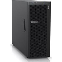
ThinkSystem ST550 - Server LENOVO - Free user manual and instructions
Find the device manual for free ThinkSystem ST550 LENOVO in PDF.


| Product Type | Tower Server |
| Brand | Lenovo |
| Model | ThinkSystem ST550 |
| Processor | Intel Xeon Scalable (1st or 2nd Gen), up to 28 cores |
| Memory | Up to 1.5 TB DDR4, 24 slots (RDIMM/LRDIMM) |
| Storage | Up to 8x 3.5" SAS/SATA or 16x 2.5" drives; hot-swap capable |
| RAID Support | Hardware RAID 0,1,5,6,10 (optional controller) |
| Power Supply | Dual redundant, 550W / 750W / 1100W AC |
| Dimensions (H x W x D) | 17.5 in (445 mm) x 8.7 in (221 mm) x 26.8 in (681 mm) |
| Weight | Approximately 55 lb (25 kg) depending on configuration |
| Cooling | 7 hot-swap fans (redundant) |
| Management | Lenovo XClarity Controller (IPMI 2.0) |
| Expansion Slots | 8 PCIe 3.0 slots (x8 or x16) |
| Network | 2x 1GbE ports (integrated) |
| Operating Systems | Windows Server, Linux (Red Hat, SUSE, VMware ESXi) |
| Security Features | TPM 2.0, Secure Boot, chassis intrusion detection |
| Included Accessories | Quick start guide, power cables, rails (optional) |
| Warranty | 3-year parts and labor (on-site), extendable |
| Maintenance | Tool-less access to drives, fans, PSU; replaceable components |
| Repairability | Modular design; most parts customer replaceable (CRU) |
Frequently Asked Questions - ThinkSystem ST550 LENOVO
User questions about ThinkSystem ST550 LENOVO
0 question about this device. Answer the ones you know or ask your own.
Ask a new question about this device
Download the instructions for your Server in PDF format for free! Find your manual ThinkSystem ST550 - LENOVO and take your electronic device back in hand. On this page are published all the documents necessary for the use of your device. ThinkSystem ST550 by LENOVO.
USER MANUAL ThinkSystem ST550 LENOVO
natural_image
Hexagonal grid pattern with colored hexagons (black, green, blue, orange, red, yellow) arranged in a curved sequence (no text or symbols)Machine Types: 7X09 and 7X10
Note
Before using this information and the product it supports, be sure to read and understand the safety information and the safety instructions, which are available at:
http://thinksystem.lenovofiles.com/help/topic/safety_documentation/pdf_files.html
In addition, ensure that you are familiar with the terms and conditions of the Lenovo warranty for your server, which can be found at:
http://datacentersupport.lenovo.com/warrantylookup
First Edition (August 2017)
© Copyright Lenovo 2017.
LIMITED AND RESTRICTED RIGHTS NOTICE: If data or software is delivered pursuant to a General Services Administration "GSA" contract, use, reproduction, or disclosure is subject to restrictions set forth in Contract No. GS-35F-05925.
Contents
Safety....iii
Safety inspection checklist ..... iv
Chapter 1. Introduction ..... 1
Server form factor ..... 2
Specifications....3
Firmware updates....7
Configuring the LAN over USB interface manually. 10
Installing the LAN over USB Windows device driver....10
Tech Tips....11
Security advisories ..... 11
Power on the server ..... 11
Power off the server....11
Chapter 2. Server components ..... 13
Front view 13
Front panel....16
Rear view....18
Rear view LEDs....21
System board components ..... 24
System board jumpers ..... 25
Internal cable routing....27
Front panel....29
Optical drive....30
Tape drive....31
Power interface board ..... 33
Fixed power supply 34
Graphics adapter 35
Simple-swap-drive backplate ..... 36
Hot-swap-drive backplane. 38
Parts list. 49
Power cords ..... 53
Chapter 3. Hardware replacement procedures....55
Installation Guidelines ..... 55
System reliability guidelines ..... 56
Handling static-sensitive devices ..... 56
Front door replacement. 57
Remove the front door . . . . . . . . . 57
Install the front door 58
Foot stands replacement ..... 59
Remove the foot stands. . . . . . . . . . 59
Install the foot stands. 60
Rack latch replacement. 61
Remove a rack latch 61
Install a rack latch....62
Server cover replacement....63
Remove the server cover 63
Install the server cover ..... 64
RAID super capacitor module replacement . . . . 65
Remove a RAID super capacitor module . . . 65
Install a RAID super capacitor module ..... 66
Air baffle replacement ..... 67
Remove the air baffle . . . . . . . . . . . 67
Install the air baffle . . . . . . . . . . . . 68
Front fan replacement 69
Remove a front fan....70
Install a front fan. 71
Rear fan replacement 72
Remove the rear fan 73
Install the rear fan . . . . . . . . . . . . . 74
PCIe adapter holder replacement ..... 74
Remove the PCIe adapter holder ..... 75
Install the PCIe adapter holder ..... 75
Front bezel replacement ..... 76
Remove the front bezel ..... 76
Install the front bezel ..... 77
Front panel replacement ..... 78
Remove the front panel ..... 78
Install the front panel....79
Optical drive or tape drive replacement ..... 80
Remove an optical drive or a tape drive. . . . 81
Install an optical drive or a tape drive. . . . . 83
Simple-swap drive replacement ..... 86
Remove a simple-swap drive. . . . . . . . 86
Install a simple-swap drive. 87
Hot-swap drive replacement....89
Remove a hot-swap drive ..... 90
Install a hot-swap drive ..... 91
Simple-swap-drive backplate replacement . . . . 93
Remove a simple-swap-drive backplate . . . 94
Install a simple-swap-drive backplate . . . . 95
Hot-swap-drive backplane replacement ..... 95
Remove the backplane for four 2.5-inch hot-swap drives 96
Install the backplane for four 2.5-inch hot-swap drives ..... 97
Remove the backplane for eight 2.5-inch hot-swap drives 98
Install the backplane for eight 2.5-inch hot-swap drives 99
Remove the backplane for four 3.5-inch hot-swap drives....99
Install the backplane for four 3.5-inch hot-swap drives....101
Expansion drive cage replacement ..... 102
Remove the expansion drive cage ..... 102
Install the expansion drive cage. . . . . . . 103
DIMM replacement ..... 105
Remove a DIMM. 105
DIMM installation rules ..... 106
Install a DIMM ..... 110
PCIe adapter retainer replacement ..... 111
Remove the PCIe adapter retainer ..... 111
Install the PCIe adapter retainer. . . . . . . 112
PCIe adapter replacement. . . . . . . . . . 113
Remove a PCIe adapter ..... 113
Install a PCIe adapter ..... 114
CMOS battery replacement ..... 116
Remove the CMOS battery ..... 116
Install the CMOS battery ..... 117
Serial port module replacement ..... 119
Remove the serial port module ..... 119
Install the serial port module ..... 120
M.2 backplane and M.2 drive replacement ..... 121
Remove the M.2 backplane and M.2 drive. . . 121
Adjust the retainer on the M.2 backplane . . . 122
Install the M.2 backplane and M.2 drive. . . . 123
TCM replacement (for China only). ..... 125
Remove the TCM (for China only) ..... 126
Install the TCM (for China only) ..... 127
Intrusion switch replacement ..... 129
Remove the intrusion switch ..... 129
Install the intrusion switch ..... 129
Fixed power supply replacement ..... 130
Remove the fixed power supply. . . . . . . 130
Install the fixed power supply. . . . . . . 135
Hot-swap power supply replacement ..... 139
Remove a hot-swap power supply. . . . . . 139
Install a hot-swap power supply ..... 144
Power interface board replacement ..... 149
Remove the power interface board ..... 149
Install the power interface board ..... 150
Hot-swap power supply cage replacement . . . . 151
Remove the hot-swap power supply cage. . . 151
Install the hot-swap power supply cage. . . . 152
Processor and heat sink replacement ..... 154
Remove a processor and heat sink ..... 154
Install a processor and heat sink ..... 157
System board replacement ..... 161
Remove the system board ..... 162
Install the system board ..... 163
Update the Universal Unique Identifier
(UUID)....164
Update the DMI/SMBIOS data ..... 166
Enable TPM/TCM 168
Enable UEFI Secure Boot ..... 170
Complete the parts replacement ..... 170
Chapter 4. Problem determination .....173
Event logs 173
General problem determination procedures . . . . 175
Resolving suspected power problems . . . . 175
Resolving suspected Ethernet controller
problems....176
Troubleshooting by symptom ..... 176
Power on and power off problems ..... 177
Memory problems ..... 178
Hard disk drive problems ..... 179
Monitor and video problems ..... 181
Keyboard, mouse, or USB-device
problems....182
Optional-device problems ..... 183
Serial-device problems ..... 185
Intermittent problems. 185
Power problems ..... 186
Network problems ..... 186
Observable problems. 187
Software problems. 189
Appendix A. Getting help and technical assistance .....191
Before you call....191
Collecting service data ..... 192
Contacting Support 193
Appendix B. Notices....195
Trademarks 196
Important notes....196
Particulate contamination ..... 196
Telecommunication regulatory statement. . . . . 197
Electronic emission notices ..... 197
Taiwan BSMI RoHS declaration ..... 198
Taiwan import and export contact information . . . 198
Index .....199
Safety
Before installing this product, read the Safety Information.
Safety inspection checklist
Use the information in this section to identify potentially unsafe conditions with your server. As each machine was designed and built, required safety items were installed to protect users and service technicians from injury.
CAUTION: This equipment must be installed by trained service personnel, as defined by the NEC and IEC 60950-1, Second Edition, the standard for Safety of Information Technology Equipment. Lenovo assumes you are qualified in the servicing of equipment and trained in recognizing hazards in products with hazardous energy levels.
Important: Electrical grounding of the server is required for operator safety and correct system function. Proper grounding of the electrical outlet can be verified by a certified electrician.
Use the following checklist to verify that there are no potentially unsafe conditions:
- Make sure that the power is off and the power cord is disconnected.
-
Check the power cord.
-
Make sure that the third-wire ground connector is in good condition. Use a meter to measure third-wire ground continuity for 0.1 ohm or less between the external ground pin and the frame ground.
- Make sure that the power cord is the correct type.
To view the power cords that are available for the server:
a. Go to:
http://lesc.lenovo.com
b. In the Customize a Model pane:
1) Click Select Options/Parts for a Model.
2) Enter the machine type and model for your server.
c. Click the Power tab to see all line cords.
- Make sure that the insulation is not frayed or worn.
- Check for any obvious non-Lenovo alterations. Use good judgment as to the safety of any non-Lenovo alterations.
- Check inside the server for any obvious unsafe conditions, such as metal filings, contamination, water or other liquid, or signs of fire or smoke damage.
- Check for worn, frayed, or pinched cables.
- Make sure that the power-supply cover fasteners (screws or rivets) have not been removed or tampered with.
Chapter 1. Introduction
The ThinkSystem ST550 server is a 4U tower server designed for performance and expansion for various IT workloads. With the modular design, the server is flexible to be customized for maximum storage capacity or high storage density with selectable input/output options and tiered system management.
Performance, ease of use, reliability, and expansion capabilities were key considerations in the design of the server. These design features make it possible for you to customize the system hardware to meet your needs today and provide flexible expansion capabilities for the future.
The server comes with a limited warranty. For details about the warranty, see: https://datacentersupport.lenovo.com/us/en/documents/ht100742
For details about your specific warranty, see: http://datacentersupport.lenovo.com/warrantylookup
Identifying your server
When you contact Lenovo for help, the machine type and serial number information helps support technicians to identify your server and provide faster service.
The machine type and serial number are on the ID label on the front of the server.
The following illustration shows the location of the ID label.
Note: The illustrations in this document might differ slightly from your server.

Figure 1. Location of the ID label
XClarity Controller network access label
The XClarity Controller network access label is attached on the front bezel as shown. After you get the server, peel the XClarity Controller network access label away and store it in a safe place for future use.

Figure 2. Location of the XClarity Controller network access label
Quick response code
The system service label, which is on the inside of the server cover, provides a quick response (QR) code for mobile access to service information. Scan the QR code with a mobile device and a QR code reader application to get quick access to the Lenovo Service web site for this server. The Lenovo Service web site provides additional information for parts installation and replacement videos, and error codes for server support.
The following illustration shows the QR code.

Figure 3. QR code
Server form factor
The ThinkSystem ST550 server is designed to support both tower and rack form factors.
You can change the server from tower form factor to rack form factor by installing the tower-to-rack conversion kit. For instructions on how to install the tower-to-rack conversion kit, refer to the documentation that comes with the conversion kit.
Specifications
The following information is a summary of the features and specifications of the server. Depending on the model, some features might not be available, or some specifications might not apply.
Dimensions for tower form factor
• Height:
- With foot stands: 437.7 mm (17.3 inches)
- Without foot stands: 425.5 mm (16.8 inches)
• b Depth: 666.4 mm (26.3 inches)
• Width:
- With foot stands: 272.0 mm (10.7 inches)
- Without foot stands: 175.8 mm (7.0 inches)
Note: The depth is measured with power supplies installed, but without the front door installed.

natural_image
Isometric view of a rectangular prism with labeled dimensions (a, b, c) for length and height reference.Dimensions for rack form factor
- Width:
- With rack latches: 482.0 mm (19.0 inches)
- Without rack latches: 427.7 mm (16.9 inches)
• b Depth: 670.2 mm (26.4 inches)
• c Height: 175.8 mm (7.0 inches)
Note: The depth is measured with rack latches and power supplies installed.

natural_image
Isometric view of a rectangular prism with labeled dimensions (no text or symbols beyond basic geometry)Weight
Up to 36.9 kg (79.4 lb), depending on the server configuration
Processor
- Up to two Intel® Xeon® processors
- Designed for Land Grid Array (LGA) 3647 socket
For a list of supported processors, see:
http://www.lenovo.com/serverproven/
DIMM
-
Minimum: 8 GB
• Maximum: -
384 GB using registered DIMMs (RDIMMs)
- 768 GB using load-reduced DIMMs (LRDIMMs)
- Type:
- DDR4-2666
- PC4-21300: operating speed depends on CPU model and UEFI Operating Mode selection
- Single-rank, dual-rank, or quad-rank
- RDIMM and LRDIMM
- Slots: 12 DIMM slots
• Supports (depending on the model):
- 8 GB, 16 GB, and 32 GB RDIMMs
- 64 GB LRDIMMs
Note: For a list of supported DIMMs, see:
http://www.lenovo.com/serverproven/
Supported drives
The drives supported by your server vary by model.
- Storage drive
| Drive bay Supported drive type | |
| Eight 2.5-inch drive bays | Hot-swap SAS/SATA/NVMe HDD or SSD (NVMe drives are supported only in bays 4–7 if an AnyBay backplane is installed) |
| Sixteen 2.5-inch drive bays | Hot-swap SAS/SATA/NVMe HDD or SSD (NVMe drives are supported only in bays 4–7 if an AnyBay backplane is installed) |
| Twenty 2.5-inch drive bays | Hot-swap SAS/SATA/NVMe HDD or SSD (NVMe drives are supported only in bays 4–7 if an AnyBay backplane is installed) |
| Four 3.5-inch drive bays | - Simple-swap SATA HDD- Hot-swap SAS/SATA HDD or SSD |
| Eight 3.5-inch drive bays | - Simple-swap SATA HDD- Hot-swap SAS/SATA HDD or SSD |
| Eight 3.5-inch drive bays and four 2.5-inch drive bays | Hot-swap SAS/SATA HDD or SSD |
To locate the storage drives or drive bays, see "Front view" on page 13.
- Optical drive
Some server models have two optical drive bays. For more information, see “Front view” on page 13.
- Tape drive
A tape drive enables you to store data on tape media. For server models with two optical drive bays, you can install an internal tape drive in the optical-drive bay 2.
- M.2 drive
Your server supports one M.2 backplane which provides an easy way for data storage. You can install up to two M.2 drives into the M.2 backplane. For more information, see “Install the M.2 backplane and M.2 drive” on page 123.
Expansion slots
The server has six expansion slots on the system board for installing appropriate Peripheral Component Interconnect Express (PCIe) adapters.
- For processor 1
- PCIe slot 1: PCIe x8 (x8, x4, x1), full-height, half-length
- PCIe slot 2: PCIe x16 (x16, x8, x4, x1), full-height, half-length
- PCIe slot 3: PCIe x16 (x16, x8, x4, x1), full-height, full-length, double-width
- PCIe slot 6: PCIe x4 (x4, x1), full-height, full-length
- For processor 2
- PCIe slot 4: PCIe x8 (x8, x4, x1), full-height, full-length
- PCIe slot 5: PCIe x16 (x16, x8, x4, x1), full-height, full-length, double-width
The following RAID adapters can be installed in an appropriate PCIe slot.
- A RAID 530-8i SAS/SATA adapter that supports JBOD mode and RAID levels 0, 1, 5, 10, and 50
- A RAID 730-8i SAS/SATA adapter that supports JBOD mode and RAID levels 0, 1, 5, 10, and 50 (only available in China)
- A RAID 930-8i, 930-16i, or 930-24i SAS/SATA adapter that supports JBOD mode and RAID levels 0, 1, 5, 6, 10, 50, and 60
Notes:
- For server models that support NVMe drives, the NVMe adapter (also known as the NVMe switch adapter) can be installed only in PCIe slot 2.
- For RAID adapters or host bus adapters, you can install them in either PCIe slot 1 or PCIe slot 2.
- For server models with one processor, you can install a double-width graphics adapter only in PCIe slot 3. For server models with two processors, you can install up to two double-width graphics adapters in PCIe slot 3 and PCIe slot 5. After any double-width graphics adapter is installed, PCIe slot 4 or PCIe slot 6 becomes unavailable because the space is occupied by the double-width adapter.
Graphics adapters
• Full-height, half-length, and double-width
• Thermal Design Power (TDP): up to 250 watt
Notes:
- Your server supports up to two graphics adapters installed.
-
Graphics adapter is supported only when the following configuration requirements are met:
-
Fan 4 is installed.
- Two 1100-watt power supplies are installed.
- Operating temperature is lower than 30^ (86°F).
- Fan redundancy function is supported when only one graphics adapter (with TDP equal to 75 watt) is installed.
Input/Output (I/O) features
- Front panel:
- One XClarity Controller USB connector
- One USB 3.0 connector
- Rear panel:
- One VGA connector
- One XClarity Controller network connector
- Two Ethernet connectors
- Two USB 3.0 connectors
- Four USB 2.0 connectors
System fans
• One processor: two fans (fan 1 and 2) or three fans (fan 1, 2, and 4)
- Two processors: three fans (fan 1, 2, and 3) or four fans (fan 1, 2, 3, and 4)
Notes:
- Fan 3 is required if the expansion drive cage is installed.
• Fan 4 is optional and is the redundant fan.
- If your server comes with only one processor, two or three system fans are adequate to provide proper cooling. However, you must keep the location for fan 3 occupied by a fan filler to ensure proper airflow.
Power supplies
• One fixed 450-watt power supply
• One or two hot-swap power supplies for redundancy support
- 550-watt ac 80 PLUS Platinum
- 750-watt ac 80 PLUS Platinum
- 750-watt ac 80 PLUS Titanium
- 1100-watt ac 80 PLUS Platinum
Electrical input
• ac input (50 Hz to 60 Hz) required
- Input voltage low range:
- Minimum: 100 V ac
- Maximum: 127 V ac
- Input voltage high range:
- Minimum: 200 V ac
- Maximum: 240 V ac
Note: For server models with 750-watt ac 80 PLUS Titanium power supplies, the 100 V –127 V ac input voltage is not supported.
CAUTION:
240 V dc input (input range: 180-300 V dc) is supported in China ONLY. Power supply with 240 V dc input cannot support hot plugging power cord function. Before removing the power supply with dc input, please turn off server or disconnect dc power sources at the breaker panel or by turning off the power source. Then, remove the power cord.
Environment
The server is supported in the following environment:
- Air temperature:
- Operating:
- ASHRAE class A2: 10–35°C (50–95°F); when the altitude exceeds 900 m (2953 ft), the maximum ambient temperature value decreases by 1°C (1.8°F) with every 300 m (984 ft) of altitude increase.
- ASHRAE class A3: 5–40°C (41–104°F); when the altitude exceeds 900 m (2953 ft), the maximum ambient temperature value decreases by 1°C (1.8°F) with every 175 m (574 ft) of altitude increase.
- ASHRAE class A4: 5–45°C (41–113°F); when the altitude exceeds 900 m (2953 ft), the maximum ambient temperature value decreases by 1°C (1.8°F) with every 125 m (410 ft) of altitude increase.
- Server off: 5–45°C (41–113°F)
- Shipping or storage: -40–60°C (-40–140°F)
• Maximum altitude: 3050 m (10 000 ft)
• Relative humidity (non-condensing):
- Operating:
- ASHRAE class A2: 8%–80%; maximum dew point: 21°C (70°F)
- ASHRAE class A3: 8%–85%; maximum dew point: 24°C (75°F)
- ASHRAE class A4: 8%–90%; maximum dew point: 24°C (75°F)
- Shipping or storage: 8%–90%
• Particulate contamination
Attention: Airborne particulates and reactive gases acting alone or in combination with other environmental factors such as humidity or temperature might pose a risk to the server. For information about the limits for particulates and gases, see “Particulate contamination” on page 196.
Note: Your server complies with ASHRAE class A2 specifications. The server performance might be impacted when the operating temperature is outside the ASHRAE A2 specifications. Depending on the hardware configuration, some server models comply with ASHRAE class A3 and class A4 specifications. To comply with ASHRAE class A3 and class A4 specifications, the server models must meet the following hardware configuration requirements at the same time:
- Fan 4 installed
- Two hot-swap power supplies installed
• NVMe SSD not installed
• Graphics adapters not installed - SAS drives with capacity larger than or equal to 2 TB not installed in the expansion drive cage
Firmware updates
Several options are available to update the firmware for the server.
You can use the tools listed here to update the most current firmware for your server and the devices that are installed in the server.
Note: Lenovo typically releases firmware in bundles called UpdateXpress System Packs (UXSPs). To ensure that all of the firmware updates are compatible, you should update all firmware at the same time. If you are updating firmware for both the Lenovo XClarity Controller and UEFI, update the firmware for Lenovo XClarity Controller first.
Important terminology
- In-band update. The installation or update is performed using a tool or application within an operating system that is executing on the server's core CPU.
- Out-of-band update. The installation or update is performed by the Lenovo XClarity Controller collecting the update and then directing the update to the target subsystem or device. Out-of-band updates have no
dependency on an operating system executing on the core CPU. However, most out-of-band operations do require the server to be in the S0 (Working) power state.
- On-Target update. The installation or update is initiated from an Operating System executing on the server's operating system.
- Off-Target update. The installation or update is initiated from a computing device interacting directly with the server's Lenovo XClarity Controller.
- UpdateXpress System Packs (UXSPs). UXSPs are bundled updates designed and tested to provide the interdependent level of functionality, performance, and compatibility. UXSPs are server machine-type specific and are built (with firmware and device driver updates) to support specific Windows Server, Red Hat Enterprise Linux (RHEL) and SUSE Linux Enterprise Server (SLES) operating system distributions. Machine-type-specific firmware-only UXSPs are also available.
See the following table to determine the best Lenovo tool to use for installing and setting up the firmware:
| Tool | In-band update | Out-of-band update | On-target update | Off-target update | Graphical user interface | Command-line interface | Supports UXSPs |
| Lenovo XClarity Provisioning ManagerLimited to core system firmware only. | √ √ | √ √ | |||||
| Lenovo XClarity ControllerSupports core system firmware and most advanced I/O option firmware updates | √ √ | √ √ | |||||
| Lenovo XClarity Essentials OneCLISupports all core system firmware, I/O firmware, and installed operating system driver updates | √ √ | √ √ | |||||
| Lenovo XClarity Essentials UpdateXpressSupports all core system firmware, I/O firmware, and installed operating system driver updates | √ √ | √ √ | |||||
| Lenovo XClarity AdministratorSupports core system firmware and I/O firmware updates | √ √ | √ √ |
The latest firmware can be found at the following site:
http://datacentersupport.lenovo.com/us/en/products/servers/thinksystem/st550/7X09/downloads
- Lenovo XClarity Provisioning Manager
From Lenovo XClarity Provisioning Manager, you can update the Lenovo XClarity Controller firmware, the UEFI firmware, and the Lenovo XClarity Provisioning Manager software.
Note: By default, the Lenovo XClarity Provisioning Manager Graphical User Interface is displayed when you press F1. If you have changed that default to be the text-based system setup, you can bring up the Graphical User Interface from the text-based system setup interface.
Additional information about using Lenovo XClarity Provisioning Manager to update firmware is available at:
http://sysmgt.lenovofiles.com/help/topic/LXPM/platform_update.html
- Lenovo XClarity Controller
If you need to install a specific update, you can use the Lenovo XClarity Controller interface for a specific server.
Notes:
- To perform an in-band update through Windows or Linux, the operating system driver must be installed and the Ethernet-over-USB (sometimes called LAN over USB) interface must be enabled.
Additional information about configuring Ethernet over USB is available at:
http://sysmgt.lenovofiles.com/help/topic/com.lenovo.systems.management.xcc.doc/NN1ia_c_configuringUSB.html
- If you update firmware through the Lenovo XClarity Controller, make sure that you have downloaded and installed the latest device drivers for the operating system that is running on the server.
Specific details about updating firmware using Lenovo XClarity Controller are available at: http://sysmgt.lenovofiles.com/help/topic/com.lenovo.systems.management.xcc.doc/NN1ia_c_manageserverfirmware.html
• Lenovo XClarity Essentials OneCLI
Lenovo XClarity Essentials OneCLI is a collection of command line applications that can be used to manage Lenovo servers. Its update application can be used to update firmware and device drivers for your servers. The update can be performed within the host operating system of the server (in-band) or remotely through the BMC of the server (out-of-band).
Specific details about updating firmware using Lenovo XClarity Essentials OneCLI is available at: http://sysmgt.lenovofiles.com/help/topic/toolsctr_cli_lenovo/onecli_c_update.html
- Lenovo XClarity Essentials UpdateXpress
Lenovo XClarity Essentials UpdateXpress provides most of OneCLI update functions through a graphical user interface (GUI). It can be used to acquire and deploy UpdateXpress System Pack (UXSP) update packages and individual updates. UpdateXpress System Packs contain firmware and device driver updates for Microsoft Windows and for Linux.
You can obtain Lenovo XClarity Essentials UpdateXpress from the following location:
https://datacentersupport.lenovo.com/us/en/solutions/ht503692
- Lenovo XClarity Administrator
If you are managing multiple servers using the Lenovo XClarity Administrator, you can update firmware for all managed servers through that interface. Firmware management is simplified by assigning firmware-compliance policies to managed endpoints. When you create and assign a compliance policy to managed endpoints, Lenovo XClarity Administrator monitors changes to the inventory for those endpoints and flags any endpoints that are out of compliance.
Specific details about updating firmware using Lenovo XClarity Administrator are available at:
http://sysmgt.lenovofiles.com/help/topic/com.lenovo.lxca.doc/update_fw.html
Configuring the LAN over USB interface manually
To perform a firmware update through the operating system using Lenovo XClarity Essentials OneCLI, the Lenovo XClarity Controller must be configured to use the LAN over USB interface. The firmware update package attempts to perform the setup automatically, if needed. If the automatic setup fails or if you prefer to set up the LAN over USB manually, use one of the following procedures.
Additional information about using the Lenovo XClarity Controller to enable LAN over USB is available at:
http://sysmgt.lenovofiles.com/help/topic/com.lenovo.systems.management.xcc.doc/NN1ia_c_configuringUSB.html
Installing the LAN over USB Windows device driver
When you install a Windows operating system, there might be an unknown RNDIS device in the Device Manager. Lenovo provides a Windows INF file that identifies this device.
Complete the following steps to install ibm_rndis_server_os.inf:
Note: You only have to perform these steps if the compute node is running a Windows operating system and the ibm_rndis_server_os.inf file has not been previously installed. The file only has to be installed once. It is required by Windows operating systems to detect and use the LAN over USB functionality.
Step 1. Click Administrative Tools → Computer Management → Device Manager and find the RNDIS Device. Click Properties → Driver → Reinstall driver. Point the server to the \Windows\inf directory where it can find the ibm_rndis_server_os.inf file and install the device.
Step 2. Click Administrative Tools → Device Manager. Right-click Network adapters and select Scan for hardware changes. A small pop-up confirms that the Ethernet device is found and installed. The New Hardware Wizard starts automatically.
Step 3. When you are prompted Can Windows connect to Windows Update to search for software?, select No, not this time. Click Next to continue.
Step 4. When you are prompted What do you want the wizard to do?, select Install from a list or specific location (Advanced). Click Next to continue.
Step 5. When you are prompted Please choose your search and installation options, select Don't search. I will choose the driver to install. Click Next to continue.
Step 6. When you are prompted Select a hardware type, and then click Next, select Network adapters. Click Next to continue.
Step 7. When you are prompted with the statement Completing the Found New Hardware Wizard, click Finish. A new local area connection appears. If the message This connection has limited or no connectivity is displayed, ignore this message.
Step 8. Return to the Device Manager. Lenovo USB Remote NDIS Network Device appears under Network Adapters.
Step 9. Use the Lenovo XClarity Controller interface to view or set the IP address for the LAN adapter.
Additional information about using the Lenovo XClarity Controller to configure LAN over USB is available at:
http://sysmgt.lenovofiles.com/help/topic/com.lenovo.systems.management.xcc.doc/NN1ia_c_configuringUSB.html
Tech Tips
Lenovo continually updates the support website with the latest tips and techniques that you can use to solve issues that you might have with your server. These Tech Tips (also called retain tips or service bulletins) provide procedures to work around issues related to the operation of your server.
To find the Tech Tips available for your server:
- Go to http://datacentersupport.lenovo.com and navigate to the support page for your server.
- Click How-tos & Solutions.
Expand Symptom to choose a category for the type is problem that you are having.
Security advisories
Lenovo is committed to developing products and services that adhere to the highest security standards in order to protect our customers and their data. When potential vulnerabilities are reported, it is the responsibility of the Lenovo Product Security Incident Response Team (PSIRT) to investigate and provide information to our customers so they may put mitigation plans in place as we work toward providing solutions.
The list of current advisories is available at the following location: https://datacentersupport.lenovo.com/us/en/product_security/home
Power on the server
After the server performs a short self-test (power status LED flashes quickly) when connected to input power, it enters a standby state (power status LED flashes once per second).
The server can be turned on (power LED on) in any of the following ways:
- You can press the power button.
- The server can restart automatically after a power interruption.
- The server can respond to remote power-on requests sent to the Lenovo XClarity Controller.
For information about powering off the server, see "Power off the server" on page 11.
Power off the server
The server remains in a standby state when it is connected to a power source, allowing the Lenovo XClarity Controller to respond to remote power-on requests. To remove all power from the server (power-on LED off), you must disconnect all power cables.
To place the server in a standby state (power-on LED flashes once per second):
Note: The Lenovo XClarity Controller can place the server in a standby state as an automatic response to a critical system failure.
- Start an orderly shutdown using the operating system (if supported by your operating system).
- Press the power-on button to start an orderly shutdown (if supported by your operating system).
- Press and hold the power button for more than 4 seconds to force a shutdown.
When in a standby state, the server can respond to remote power-on requests sent to the Lenovo XClarity Controller. For information about powering on the server, see “Power on the server” on page 11.
Chapter 2. Server components
This section provides information to help you locate your server components.
Front view
The front view of the server varies by model.
The illustrations in this topic show the server front views based on the supported drive bays.
Note: Your server might look different from the illustrations in this topic.
| Front view of server models with two optical drive bays and eight 3.5-inch-drive bays | Front view of server models with two optical drive bays and sixteen 2.5-inch-drive bays |
Figure 4. Front view of server models with optical drive bays
Table 1. Components on the front of server models with optical drive bays
| Callout Callout | |
| 1 Front panel | 2 Optical-drive bay 2 |
| 3 Optical-drive bay 1 | 4 Drive activity LED (green) |
| 5 Drive status LED (yellow) | 6 Foot stands |
| 7a 3.5-inch drive bays 0–3 | 7b 3.5-inch drive bays 4–7 |
| 7c 2.5-inch drive bays 0–7 | 7d 2.5-inch drive bays 8–15 |
| 8 Optical-drive status LED | 9 Optical-drive eject/close button |
| 10 Optical-drive manual-eject hole |
1 Front panel
For information about the controls, connectors, and status LEDs on the front panel, see “Front panel” on page 16.
2 Optical-drive bay 2
The 5.25-inch optical-drive bay 2 is for a secondary optical drive or a tape drive. Some models have a secondary optical drive or a tape drive installed.
3 Optical-drive bay 1
Depending on the model, your server might come with an optical drive installed in the 5.25-inch optical-drive bay 1.
4 Drive activity LED
5 Drive status LED
Each hot-swap drive has two LEDs.
| Drive LED | Status | Description |
| 4 Drive activity LED (left) | Solid green | The drive is powered but not active. |
| Blinking green The drive is active. | ||
| 5 Drive status LED (right) Solid yellow | The drive has an error. | |
| Blinking yellow (blinking slowly, about one flash per second) | ||
| Blinking yellow (blinking rapidly, about four flashes per second) | ||
6 Foot stands
For tower-form-factor models, your server comes with four foot stands. To help the server stand steadily, ensure that you install the foot stands correctly as shown. See “Install the foot stands” on page 60.
7a 7b c 7d Drive bays
The drive bays are used to install 3.5-inch or 2.5-inch storage drives. When you install drives, follow the order of the drive bay numbers. The EMI integrity and cooling of the server are protected by having all drive bays occupied. The vacant drive bays must be occupied by drive bay fillers or drive fillers. Depending on the model, your server supports one of the following drive bay configurations:
• Four 3.5-inch-drive bays
• Eight 3.5-inch-drive bays
• Eight 2.5-inch-drive bays
- Sixteen 2.5-inch-drive bays
Note: For the 2.5-inch-drive-bay models that support NVMe drives, you can install up to four NVMe drives in bays 4–7.
8 Optical-drive status LED
The optical-drive status LED is blinking in green when the optical drive is working or in the POST process.
9 Optical-drive eject/close button
Press this button to eject or close the optical drive when the server power is on.
10 Optical-drive manual-eject hole
Insert a straightened paper clip into the optical-drive manual-eject hole to eject the disc tray when the eject/close button does not work.
| Front view of server models with eight 3.5-inch-drive bays and four 2.5-inch-drive bays | Front view of server models with twenty 2.5-inch-drive bays |
Figure 5. Front view of server models without optical drive bays
Table 2. Components on the front of server models without optical drive bays
| Callout Callout | |
| 1 Front panel | 2 Expansion drive cage |
| 3 Drive activity LED (green) | 4 Drive status LED (yellow) |
| 5 Foot stands | 6a 2.5-inch drive bays 8–11 |
| 6b 2.5-inch drive bays 16–19 | 6c 2.5-inch drive bays 8–15 |
| 6d 2.5-inch drive bays 0–7 | 7a 3.5-inch drive bays 4–7 |
| 7b 3.5-inch drive bays 0–3 |
1 Front panel
For information about the controls, connectors, and status LEDs on the front panel, see "Front panel" on page 16.
2 Expansion drive cage
For some server models, your server comes with an expansion drive cage. You can install up to four 2.5-inch SAS/SATA drives to the cage.
3 Drive activity LED
4 Drive status LED
Each hot-swap drive has two LEDs.
| Drive LED | Status | Description |
| 3 Drive activity LED (left) Solid | Solid green | The drive is powered but not active. |
| Blinking green The drive is active. | ||
| 4 Drive status LED (right) Solid | Solid yellow The drive has an error. | |
| Blinking yellow (blinking slowly, about one flash per second) | The drive is being rebuilt. | |
| Blinking yellow (blinking rapidly, about four flashes per second) | The RAID controller is locating the drive. |
5 Foot stands
For tower-form-factor models, your server comes with four foot stands. To help the server stand steadily, ensure that you install the foot stands correctly as shown. See “Install the foot stands” on page 60.
6a 6b c 6d 7b drive bays
The drive bays are used to install 3.5-inch or 2.5-inch storage drives. The EMI integrity and cooling of the server are protected by having all drive bays occupied. The vacant drive bays must be occupied by drive bay fillers or drive fillers. When you install drives, follow the order of the drive bay numbers.
Note: For the 2.5-inch-drive-bay models that support NVMe drives, you can install up to four NVMe drives in bays 4–7.
Front panel
The front panel of the server provides controls, connectors, and LEDs.
The following illustration shows the control, connectors, and LEDs on the front panel of the server.
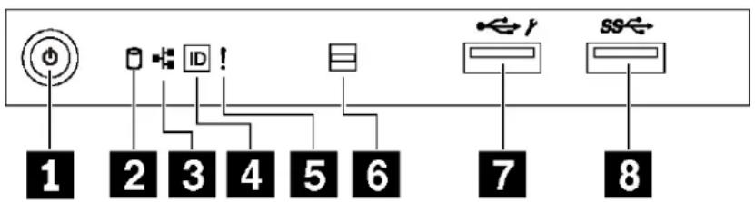
Figure 6. Front panel
Table 3. Components on the front panel
| Callout Callout | |
| 1 Power button with power status LED (green) | 2 Simple-swap-drive activity LED (green) |
| 3 Network activity LED (green) | 4 System ID button with system ID LED (blue) |
| 5 System error LED (yellow) | 6 Opening for temperature sensor |
| 7 XClarity Controller USB connector | 8 USB 3.0 connector |
■ Power button with power status LED
You can press the power button to turn on the server when you finish setting up the server. You also can hold the power button for several seconds to turn off the server if you cannot turn off the server from the operating system. The power status LED helps you to determine the current power status.
| Status Color | Description | |
| Solid on Green The | server is on | and running. |
| Slow blinking (about one flash per second) | Green The | server is off and is ready to be powered on (standby state). |
| Fast blinking (about four flashes per second) | Green The | server is off, but the XClarity Controller is initializing, and the server is not ready to be powered on. |
| Off | None There | is no ac power applied to the server. |
2 Simple-swap-drive activity LED
The simple-swap-drive activity LED is only for server models with simple-swap storage drives.
| Status Color | Description | |
| Solid on Green The simple-swap drive is active. | ||
| Off None The simple-swap drive is not active. | ||
3 Network activity LED
The network activity LED on the front panel helps you identify the network connectivity and activity.
| Status Color | Description | |
| On Green The server is connected to a network. | ||
| Blinking Green The network is connected and active. | ||
| Off None | The server is disconnected from the network. | |
System ID button with system ID LED
Use this system ID button and the blue system ID LED to visually locate the server. A system ID LED is also located on the rear of the server. Each time you press the system ID button, the state of both the system ID LEDs changes. The LEDs can be changed to on, blinking, or off. You can also use the Lenovo XClarity
Controller or a remote management program to change the state of the system ID LEDs to assist in visually locating the server among other servers.
If the XClarity Controller USB connector is set to have both the USB 2.0 function and XClarity Controller management function, you can press the system ID button for three seconds to switch between the two functions.
System error LED
The system error LED provides basic diagnostic functions for your server.
| Status Color | Description Action | ||
| On | Yellow An error has been detected on the server.Causes might include one or more of the following errors:The temperature of the server reached the non-critical temperature threshold.The voltage of the server reached the non-critical voltage threshold.A fan has been detected to be running at low speed.A fan has been removed.The power supply has a critical error.The power supply is not connected to the power. | Check the event log to determine the exact cause of the error. | |
| Off None The server is off or the server is on and is working correctly. | None. | ||
6 Opening for temperature sensor
Used to detect the surrounding temperature.
7 XClarity Controller USB connector
Depending on the setting, this connector supports USB 2.0 function, XClarity Controller management function, or both.
- If the connector is set for USB 2.0 function, you can attach a device that requires a USB 2.0 connection, such as a keyboard, a mouse, or a USB storage device.
- If the connector is set for XClarity Controller management function, you can attach a mobile device installed with the application to run XClarity Controller event logs.
- If the connector is set to have both functions, you can press the system ID button for three seconds to switch between the two functions.
8 USB 3.0 connector
Used to attach a device that requires a USB 2.0 or 3.0 connection, such as a keyboard, a mouse, or a USB flash drive.
Rear view
The rear of the server provides access to several connectors and components.
Rear view of server models with a fixed power supply

Figure 7. Rear view of server models with a fixed power supply
Table 4. Components on the rear of server models with a fixed power supply
| Callout Callout | |
| 1 Fixed power supply | 2 USB 2.0 connectors (2) |
| 3 USB 3.0 connectors (2) | 4 XClarity Controller network connector |
| 5 USB 2.0 connectors (2) | 6 Ethernet connectors (2) |
| 7 VGA connector | 8 NMI button |
| 9 Serial-port-module slot | 10 PCIe slot 1 |
| 11 PCIe slot 2 PCIe slot 3 | |
| 13 PCIe slot 4 PCIe slot 5 | |
| 15 PCIe slot 6 |
Fixed power supply
Used to connect the power cord.
23 USB connectors
Used to attach a device that requires a USB 2.0 or 3.0 connection, such as a keyboard, a mouse, or a USB flash drive.
4 XClarity Controller network connector
Used to attach an Ethernet cable to manage the system using XClarity Controller.
6 Ethernet connectors
Used to attach an Ethernet cable for a LAN. Each Ethernet connector has two status LEDs to help you identify the Ethernet connectivity and activity. For more information, see “Rear view LEDs” on page 21.
7 VGA connector
Used to attach a VGA-compatible video device, such as a VGA monitor.
8 NMI button
Press this button to force a nonmaskable interrupt (NMI) to the processor. By this way, you can blue screen the server and take a memory dump. You might have to use a pen or the end of a straightened paper clip to press the button.
9 Serial-port-module slot
Used to install a serial port module. The serial port module is available on some models. For instructions on how to install the serial port module, see "Install the serial port module" on page 120.
10 11 2 13 1 15 Cle slots
Your server has six PCIe slots on the system board for you to install appropriate PCIe adapters. For information about the PCIe slots, see "Specifications" on page 3.
Rear view of server models with two hot-swap power supplies

Figure 8. Rear view of server models with two hot-swap power supplies
Table 5. Components on the rear of server models with two hot-swap power supplies
| Callout Callout | |
| 1 Power supply 1 | 2 Power supply 2 (available on some models or available as an option) |
| 3 USB 2.0 connectors (2) | 4 USB 3.0 connectors (2) |
| 5 XClarity Controller network connector | 6 USB 2.0 connectors (2) |
| 7 Ethernet connectors (2) | 8 VGA connector |
| 9 NMI button | 10 Serial-port-module slot |
| 11 PCIe slot 1 PCIe slot 2 | |
| 13 PCIe slot 3 PCIe slot 4 | |
| 15 PCIe slot 5 PCIe slot 6 |
1 Power supply 1
2 Power supply 2 (available on some models or available as an option)
The hot-swap redundant power supplies help you avoid significant interruption to the operation of the system when a power supply fails. You can purchase a power supply option from Lenovo and install the power supply to provide power redundancy without turning off the server.
On each power supply, there are three status LEDs near the power cord connector. For information about the status LEDs, see “Rear view LEDs” on page 21.
34 USB connectors
Used to attach a device that requires a USB 2.0 or 3.0 connection, such as a keyboard, a mouse, or a USB flash drive.
5 XClarity Controller network connector
Used to attach an Ethernet cable to manage the system using XClarity Controller.
7 Ethernet connectors
Used to attach an Ethernet cable for a LAN. Each Ethernet connector has two status LEDs to help you identify the Ethernet connectivity and activity. For more information, see “Rear view LEDs” on page 21.
8 VGA connector
Used to attach a VGA-compatible video device, such as a VGA monitor.
9 NMI button
Press this button to force a nonmaskable interrupt (NMI) to the processor. By this way, you can blue screen the server and take a memory dump. You might have to use a pen or the end of a straightened paper clip to press the button.
10 Serial-port-module slot
Used to install a serial port module. The serial port module is available on some models. For instructions on how to install the serial port module, see "Install the serial port module" on page 120.
11 12 3 14 15 16 PCIe slots
Your server has six PCIe slots on the system board for you to install appropriate PCIe adapters. For information about the PCIe slots, see “Specifications” on page 3.
Rear view LEDs
The illustration in this section shows the LEDs on the rear the server.

Figure 9. Rear view LEDs of the server
Table 6. LEDs on the rear of the server
| Callout Callout | |
| 4 Ethernet link LED (green) | 2 Ethernet activity LED (green) |
| 3 System ID LED (blue) | 4 Power input LED (green) |
| 5 Power output LED (green) | 6 Power supply error LED (yellow) |
12 Ethernet status LEDs
Each network connector has two status LEDs.
| Ethernet status LED | Color Status | Description | |
| 1 Ethernet link LED | Green On | Network link is established. | |
| None | Off | Network link is disconnected. | |
| 2 Ethernet activity LED | Green | Blinking Network link is connected and active. | |
| None | Off The server is disconnected from a LAN. | ||
3 System ID LED
The blue system ID LED helps you to visually locate the server. A system ID LED is also located on the front of the server. Each time you press the system ID button, the state of both the system ID LEDs changes. The LEDs can be changed to on, blinking, or off. You can also use the Lenovo XClarity Controller or a remote management program to change the state of the system ID LEDs to assist in visually locating the server among other servers.
4 Power input LED
5 Power output LED
6 Power supply error LED
Each hot-swap power supply has three status LEDs.
| LED Description | |
| 4 Power input LED | Off: The power supply is disconnected from the ac power source or a power problem occurs.Green: The power supply is connected to the ac power source. |
| 5 Power output LED | Green: The server is on and the power supply is working normally.Blinking green: The power supply is in zero-output mode (standby). When the server power load is low, one of the installed power supplies enters into the standby state while the other one delivers entire load. When the power load increases, the standby power supply will switch to active state to provide sufficient power to the server.Zero-output mode is enabled by default. To disable zero-output mode, start the Setup utility, go toSystem Settings → Power → Zero Outputand selectDisable. If you disable zero-output mode, both power supplies will be in the active state.Off: The server is powered off, or the power supply is not working properly. If the server is powered on but the power output LED is off, replace the power supply. |
| 6 Power supply error LED | Off: The power supply is working normally.Yellow: The power supply has failed. To resolve the issue, replace the power supply. |
System board components
The illustration in this section shows the component locations on the system board.
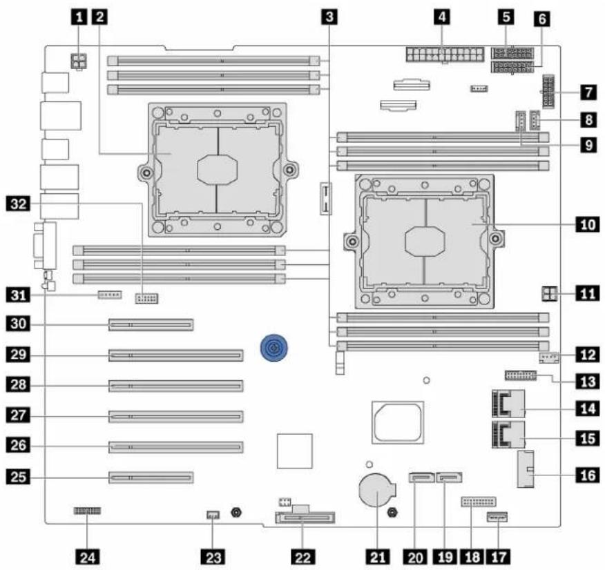
Figure 10. System board components
Table 7. Components on the system board
| Callout Callout | |
| 1 CPU 2 power connector | 2 Processor 2 socket |
| 3 DIMM slots (12) | 4 Main power connector |
| 5 Backplane 1 power connector | 6 Backplane 2 power connector |
| 7 Backplane 3 power connector | 8 System fan 2 connector |
| 9 System fan 3 connector | 10 Processor 1 socket |
| 11 CPU 1 power connector | 12 System fan 1 connector |
| 13 Power-interface-board signal connector | 14 SAS 4-7 connector |
| 15 SAS 0-3 connector | 16 Front-panel-USB connector |
| 17 Internal USB 3.0 connector | 18 Operator-information-panel connector |
| 19 Optical-drive-2 signal connector | 20 Optical-drive-1 signal connector |
| 21 CMOS battery connector | 22 M.2 module slot |
| 23 Intrusion switch connector | 24 TCM connector (for China only) |
| 25 PCIe slot 6 (for processor 1) | 26 PCIe slot 5 (for processor 2) |
| 27 PCIe slot 4 (for processor 2) | 28 PCIe slot 3 (for processor 1) |
| 29 PCIe slot 2 (for processor 1) | 30 PCIe slot 1 (for processor 1) |
| 31 System fan 4 connector | 32 Serial-port-module connector |
System board jumpers
The following illustration shows the location of the jumpers on the server.

Figure 11. System board jumpers
Table 8. Jumper description
| Jumper name Jumper number Jumper setting | ||
| 1 Force XCC update jumper | JP16 • Pins 1 and 2: The jumper is in default setting.• Pins 2 and 3: Force the Lenovo XClarity Controller to update to the latest version. | |
| 2 Force XCC reset jumper | JP19 | • Pins 1 and 2: The jumper is in default setting.• Pins 2 and 3: Reset the Lenovo XClarity Controller. |
| 3 TPM/TCM physical presence jumper* TPM: Trusted Platform Module* TCM: Trusted Cryptography Module (for China only) | JP23 • Pins 1 and 2: The jumper is in default setting.• Pins 2 and 3: TPM/TCM physical presence is asserted. | |
| 4 Clear CMOS jumper | JP76 • Pins 1 and 2: The jumper is in default setting.• Pins 2 and 3: Clear the real-time clock (RTC) registry. | |
| 5 Override power-on password jumper | JP61 • Pins 1 and 2: The jumper is in default setting.• Pins 2 and 3: Override the power-on password. | |
Important:
- Before you move the jumpers, turn off the server. Then, disconnect all power cords and external cables. Do not open your server or attempt any repair before reading and understanding the following information:
- http://thinksystem.lenovofiles.com/help/topic/safety_documentation/pdf_files.html
- "Handling static-sensitive devices" on page 56
- Any system-board switch or jumper block that is not shown in the illustrations in this document are reserved.
Internal cable routing
Some of the components in the server have internal cables and cable connectors.
To connect cables, observe the following guidelines:
- Turn off the server before you connect or disconnect any internal cables.
- See the documentation that comes with any external devices for additional cabling instructions. It might be easier for you to route cables before you connect the devices to the server.
- Cable identifiers of some cables are printed on the cables that come with the server and optional devices. Use these identifiers to connect the cables to the correct connectors.
- Ensure that the cable is not pinched and does not cover any connectors or obstruct any components on the system board.
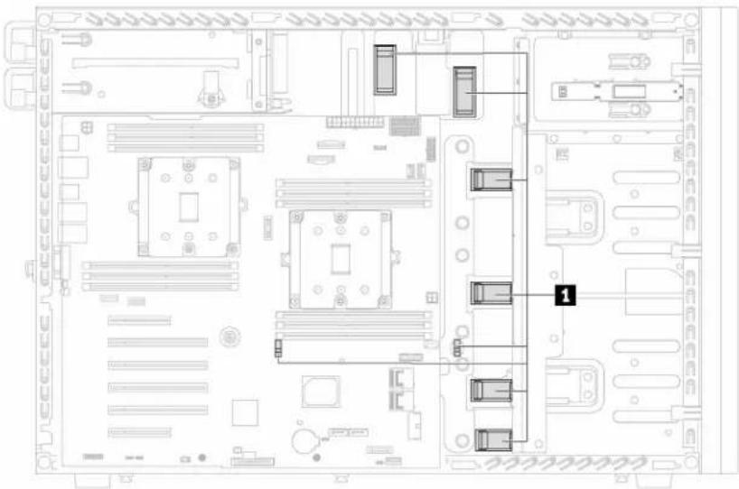
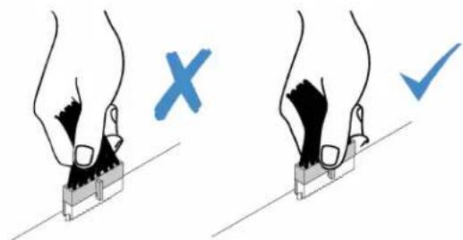
- Ensure that the cables pass through corresponding cable clips 1.
Note: Disengage all latches, release tabs, or locks on cable connectors when you disconnect cables from the system board. Failing to release them before removing the cables will damage the cable sockets on the system board, which are fragile. Any damage to the cable sockets might require replacing the system board.

Front panel
Use the section to understand the cable routing for the front panel.

Figure 12. Cable routing for the front panel
| From To | |
| 1 Operator-information-panel cable | Operator-information-panel connector on the system board |
| 2 USB cable Front-panel-USB connector on the system board |
Note: Ensure that all cables are routed through the correct cable clips.
Optical drive
Use the section to understand the cable routing for the optical drives.

Figure 13. Cable routing for the optical drives
| Cable | From To | |
| 1 Power cable | Power connector on each optical drive | Backplane 3 power connector on the system board |
| 2 Signal cable | Signal connector on the optical drive 2 | Optical-drive-2 signal connector on the system board |
| 3 Signal cable | Signal connector on the optical drive 1 | Optical-drive-1 signal connector on the system board |
Note: Ensure that all cables are routed through the correct cable clips.
Tape drive
Use the section to understand the cable routing for the tape drive.
SAS tape drive

Figure 14. Cable routing for the SAS tape drive
| Cable From To | ||
| 1 Signal cable | Signal connector on the tape drive | An available connector on the RAID adapter |
| 2 Power cable | Power connector on the tape drive | Backplane 3 power connector on the system board |
Note: Ensure that all cables are routed through the correct cable clips.
USB tape drive
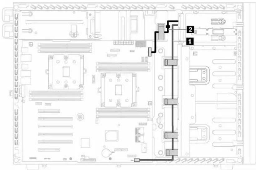
Figure 15. Cable routing for the USB tape drive
| Cable | From To | |
| 1 Signal cable | Signal connector on the tape drive | Internal USB 3.0 connector on the system board |
| 2 Power cable | Power connector on the tape drive | Backplane 3 power connector on the system board |
Note: Ensure that all cables are routed through the correct cable clips.
Power interface board
Use the section to understand the cable routing for the power interface board.

Figure 16. Cable routing for the power interface board
| Cable | From To | |
| 1 Signal cable Signal connector on the power interface board | Power-interface-board signal connector on the system board | |
| 2 Power cable Main power connector on the power interface board | Main power connector on the system board | |
| 3 CPU 1 power cable CPU 1 connector on the power interface board | CPU 1 power connector on the system board | |
| 4 CPU 2 power cable CPU 2 connector on the power interface board | CPU 2 power connector on the system board | |
Note: Ensure that all cables are routed through the correct cable clips.
Fixed power supply
Use the section to understand the cable routing for the fixed power supply.
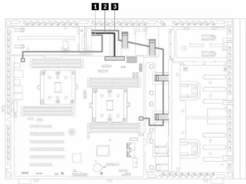
Figure 17. Cable routing for the fixed power supply
| From To | |
| 1 CPU 2 power cable CPU 2 power connector on the system board | |
| 2 Main power cable Main power connector on the system board | |
| 3 CPU 1 power cable CPU 1 power connector on the system board | |
Note: Ensure that all cables are routed through the correct cable clips.
Graphics adapter
Use the section to understand the cable routing for the graphics adapters.

Figure 18. Cable routing for the graphics adapters
| Cable | From To | |
| 1 Power cable Power connector on one graphics adapter | GPU 1 connector on the power interface board | |
| 2 Power cable Power connector on another graphics adapter | GPU 2 connector on the power interface board | |
Note: Ensure that all cables are routed through the correct cable clips.
Simple-swap-drive backplate
Use the section to understand the cable routing for the simple-swap-drive backplate.
This topic contains the following information:
- "Server models with four 3.5-inch simple-swap drives" on page 36
- "Server models with eight 3.5-inch simple-swap drives" on page 37
Server models with four 3.5-inch simple-swap drives
Use this section to understand the cable routing for server models with four 3.5-inch simple-swap drives.
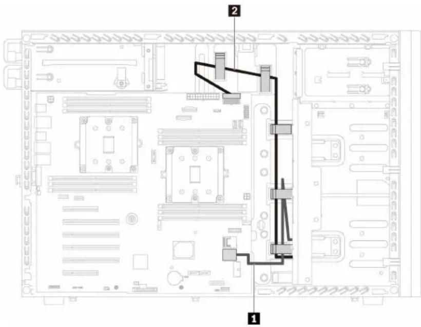
Figure 19. Cable routing for server models with four 3.5-inch simple-swap drives
Note: Ensure that all cables are routed through the correct cable clips.
| From To | |
| 1 Signal cable on the backplate | SAS 0–3 connector on the system board |
| 2 Power cable on the backplate | Backplane 1 power connector on the system board |
Server models with eight 3.5-inch simple-swap drives
Use this section to understand the cable routing for server models with eight 3.5-inch simple-swap drives.

Figure 20. Cable routing for server models with eight 3.5-inch simple-swap drives
| From To | |
| 1 Signal cable on backplate 1 | SAS 0–3 connector on the system board |
| 2 Power cable on backplate 1 | Backplane 1 power connector on the system board |
| 3 Signal cable on backplate 2 | SAS 4–7 connector on the system board |
| 4 Power cable on backplate 2 | Backplane 2 power connector on the system board |
Note: Ensure that all cables are routed through the correct cable clips.
Hot-swap-drive backplane
Use the section to understand the cable routing for hot-swap-drive backplanes.
This topic contains the following information:
- "Server models with eight 2.5-inch hot-swap drives" on page 38
- "Server models with sixteen 2.5-inch hot-swap drives" on page 40
- "Server models with twenty 2.5-inch hot-swap drives" on page 43
- "Server models with four 3.5-inch hot-swap drives" on page 45
- "Server models with eight 3.5-inch hot-swap drives" on page 46
- "Server models with eight 3.5-inch hot-swap drives and four 2.5-inch hot-swap drives" on page 47
Before you route cables for backplanes, observe the following guidelines when select a PCIe slot:
- The NVMe adapter can be installed only in PCIe slot 2.
- Internal RAID adapters can be installed in either PCIe slot 1 or PCIe slot 2.
Server models with eight 2.5-inch hot-swap drives
Use this section to understand the cable routing for server models with eight 2.5-inch hot-swap drives.
Server model: eight 2.5-inch SAS/SATA drives, one 8i RAID adapter

Figure 21. Cable routing for server models with eight 2.5-inch SAS/SATA drives and one 8i RAID adapter
Note: Ensure that all cables are routed through the correct cable clips.
| Cable From To | ||
| 1 Signal cable SAS 0 | and SAS 1 connectors on the backplane | C0 and C1 connectors on the 8i RAID adapter |
| 2 Power cable | Power connector on the backplane | Backplane 1 power connector on the system board |
Server model: four 2.5-inch SAS/SATA drives, four 2.5-inch NVMe drives, one 8i RAID adapter, one NVMe adapter

Figure 22. Cable routing for server models with four 2.5-inch SAS/SATA drives, four 2.5-inch NVMe drives, one 8i RAID adapter, and one NVMe adapter
Note: Ensure that all cables are routed through the correct cable clips.
| Cable From To | ||
| 1 Signal cable SAS 0 | and SAS 1 connectors on the backplane | C0 and C1 connectors on the 8i RAID adapter |
| 2 Power cable | Power connector on the backplane | Backplane 1 power connector on the system board |
| 3 NVMe signal cable | NVMe 0, NVMe 1, NVMe 2, and NVMe 3 connectors on the backplane | C0, C1, C2, and C3 connectors on the NVMe adapter |
Server models with sixteen 2.5-inch hot-swap drives
Use this section to understand the cable routing for server models with sixteen 2.5-inch hot-swap drives.
Server model: sixteen 2.5-inch SAS/SATA drives, two 8i RAID adapters

Figure 23. Cable routing for server models with sixteen 2.5-inch SAS/SATA drives and two 8i RAID adapters
| Cable | From To | |
| 1 Signal cable for backplane 1 S | AS 0 and SAS 1 connectors on backplane 1 | C0 and C1 connectors on one 8i RAID adapter |
| 2 Power cable for backplane 1 | Power connector on backplane 1 | Backplane 1 power connector on the system board |
| 3 Signal cable for backplane 2 S | AS 0 and SAS 1 connectors on backplane 2 | C0 and C1 connectors on another 8i RAID adapter |
| 4 Power cable for backplane 2 | Power connector on backplane 2 | Backplane 2 power connector on the system board |
Note: Ensure that all cables are routed through the correct cable clips.
Server model: sixteen 2.5-inch SAS/SATA drives, one 16i RAID adapter

Figure 24. Cable routing for server models with sixteen 2.5-inch SAS/SATA drives and one 16i RAID adapter
| Cable | From To | |
| 1 Signal cable for backplane 1 SAS 0 and SAS 1 connectors on backplane 1 | C0 and C1 connectors on the 16i RAID adapter | |
| 2 Power cable for backplane 1 | Power connector on backplane 1 | Backplane 1 power connector on the system board |
| 3 Signal cable for backplane 2 SAS 0 and SAS 1 connectors on backplane 2 | C2 and C3 connectors on the 16i RAID adapter | |
| 4 Power cable for backplane 2 | Power connector on backplane 2 | Backplane 2 power connector on the system board |
Note: Ensure that all cables are routed through the correct cable clips.
Server model: twelve 2.5-inch SAS/SATA drives, four 2.5-inch NVMe drives, one 16i RAID adapter, one NVMe adapter

Figure 25. Cable routing for server models with twelve 2.5-inch SAS/SATA drives, four 2.5-inch NVMe drives, one 16i RAID adapter, and one NVMe adapter
| Cable | From To | |
| 1 Signal cable for backplane 1 SAS | AS 0 and SAS 1 connectors on backplane 1 | C0 and C1 connectors on the 16i RAID adapter |
| 2 Power cable for backplane 1 | Power connector on backplane 1 | Backplane 1 power connector on the system board |
| 3 Signal cable for backplane 2 SAS | AS 0 and SAS 1 connectors on backplane 2 | C2 and C3 connectors on the 16i RAID adapter |
| 4 Power cable for backplane 2 | Power connector on backplane 2 | Backplane 2 power connector on the system board |
| 5 NVMe signal cable for backplane 1 | NVMe 0, NVMe 1, and NVMe 2, and NVMe 3 connectors on backplane 1 | C0, C1, C2, and C3 connectors on the NVMe adapter |
Note: Ensure that all cables are routed through the correct cable clips.
Server models with twenty 2.5-inch hot-swap drives
Use this section to understand the cable routing for server models with twenty 2.5-inch hot-swap drives.
Server model: twenty 2.5-inch SAS/SATA drives, one 24i RAID adapter

Figure 26. Cable routing for server models with twenty 2.5-inch SAS/SATA drives and one 24i RAID adapter
| Cable | From To | |
| 1 Signal cable for backplane 1 S | AS 0 and SAS 1 connectors on backplane 1 | C0 and C1 connectors on the 24i RAID adapter |
| 2 Power cable for backplane 1 | Power connector on backplane 1 | Backplane 1 power connector on the system board |
| 3 Signal cable for backplane 2 S | AS 0 and SAS 1 connectors on backplane 2 | C2 and C3 connectors on the 24i RAID adapter |
| 4 Power cable for backplane 2 | Power connector on backplane 2 | Backplane 2 power connector on the system board |
| 5 Signal cable for backplane 3 | SAS 0 connector on backplane 3 | C4 connector on the 24i RAID adapter |
| 6 Power cable for backplane 3 | Power connector on backplane 3 | Backplane 3 power connector on the system board |
Note: Ensure that all cables are routed through the correct cable clips.
Server model: sixteen 2.5-inch SAS/SATA drives, four 2.5-inch NVMe drives, one 24i RAID adapter, one NVMe adapter
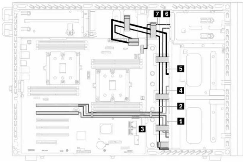
Figure 27. Cable routing for server models with sixteen 2.5-inch SAS/SATA drives, four 2.5-inch NVMe drives, one 24i RAID adapter, and one NVMe adapter
| Cable | From To | |
| 1 Signal cable for backplane 1 S | AS 0 and SAS 1 connectors on backplane 1 | C0 and C1 connectors on the 24i RAID adapter |
| 2 Power cable for backplane 1 | Power connector on backplane 1 | Backplane 1 power connector on the system board |
| 3 NVMe signal cable for backplane 1 | NVMe 0, NVMe 1, NVMe 2, and NVMe 3 connectors on backplane 1 | C0, C1, C2, and C3 connectors on the NVMe adapter |
| 4 Signal cable for backplane 2 S | AS 0 and SAS 1 connectors on backplane 2 | C2 and C3 connectors on the 24i RAID adapter |
| 5 Power cable for backplane 2 | Power connector on backplane 2 | Backplane 2 power connector on the system board |
| 6 Signal cable for backplane 3 | SAS 0 connector on backplane 3 | C4 connector on the 24i RAID adapter |
| 7 Power cable for backplane 3 | Power connector on backplane 3 | Backplane 3 power connector on the system board |
Note: Ensure that all cables are routed through the correct cable clips.
Server models with four 3.5-inch hot-swap drives
Use this section to understand the cable routing for server models with four 3.5-inch hot-swap SAS/SATA drives.
Server model: four 3.5-inch SAS/SATA drives, one 8i RAID adapter

Figure 28. Cable routing for server models with four 3.5-inch SAS/SATA drives and one 8i RAID adapter
Note: Ensure that all cables are routed through the correct cable clips.
| Cable | From To | |
| 1 Signal cable | SAS 0 connector on the backplane | C0 connector on the 8i RAID adapter |
| 2 Power cable | Power connector on the backplane | Backplane 1 power connector on the system board |
Server models with eight 3.5-inch hot-swap drives
Use this section to understand the cable routing for server models with eight 3.5-inch hot-swap SAS/SATA drives.
Server model: eight 3.5-inch SAS/SATA drives, one 8i RAID adapter
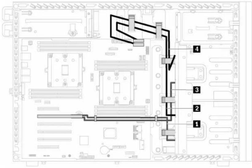
Figure 29. Cable routing for server models with eight 3.5-inch SAS/SATA drives and one 8i RAID adapter
| Cable | From To | |
| 1 Signal cable for backplane 1 | SAS 0 connector on backplane 1 | C0 connector on the 8i RAID adapter |
| 2 Power cable for backplane 1 | Power connector on backplane 1 | Backplane 1 power connector on the system board |
| 3 Signal cable for backplane 2 | SAS 0 connector on backplane 2 | C1 connector on the 8i RAID adapter |
| 4 Power cable for backplane 2 | Power connector on backplane 2 | Backplane 2 power connector on the system board |
Note: Ensure that all cables are routed through the correct cable clips.
Server models with eight 3.5-inch hot-swap drives and four 2.5-inch hot-swap drives
Use this section to understand the cable routing for server models with eight 3.5-inch hot-swap SAS/SATA drives and four 2.5-inch hot-swap SAS/SATA drives.
Server model: eight 3.5-inch hot-swap SAS/SATA drives, four 2.5-inch hot-swap SAS/SATA drives, two 8i RAID adapters
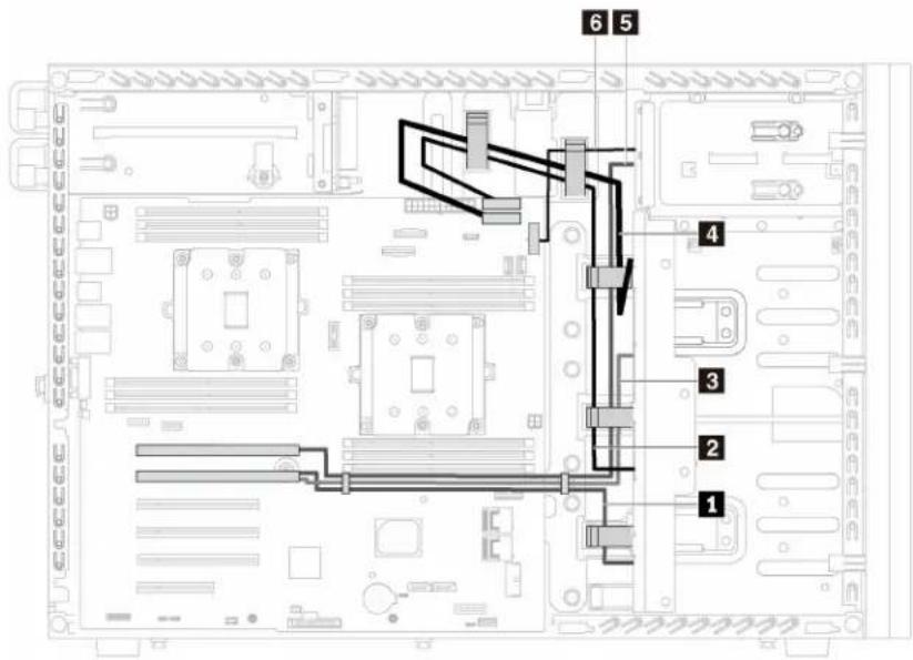
Figure 30. Cable routing for server models with eight 3.5-inch hot-swap SAS/SATA drives, four 2.5-inch hot-swap SAS/SATA drives, and two 8i RAID adapters
| Cable | From To | |
| 1 Signal cable for backplane 1 | SAS 0 connector on backplane 1 | C0 connector on one 8i RAID adapter |
| 2 Power cable for backplane 1 | Power connector on backplane 1 | Backplane 1 power connector on the system board |
| 3 Signal cable for backplane 2 | SAS 0 connector on backplane 2 | C1 connector on one 8i RAID adapter |
| 4 Power cable for backplane 2 | Power connector on backplane 2 | Backplane 2 power connector on the system board |
| 5 Signal cable for backplane 3 | SAS 0 connector on backplane 3 | C0 connector on another 8i RAID adapter |
| 6 Power cable for backplane 3 | Power connector on backplane 3 | Backplane 3 power connector on the system board |
Note: Ensure that all cables are routed through the correct cable clips.
Server model: eight 3.5-inch hot-swap SAS/SATA drives, four 2.5-inch hot-swap SAS/SATA drives, one 16i RAID adapter
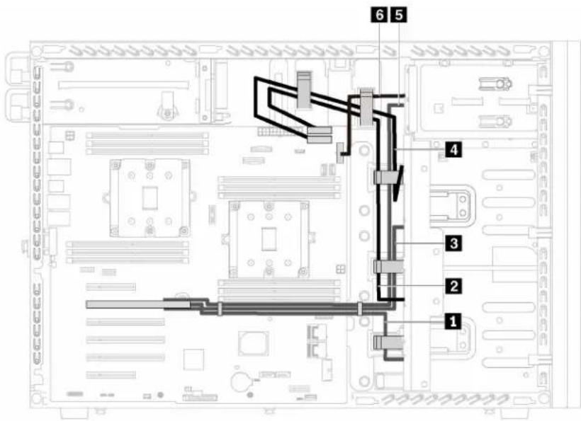
Figure 31. Cable routing for server models with eight 3.5-inch hot-swap SAS/SATA drives, four 2.5-inch hot-swap SAS/SATA drives, and one 16i RAID adapter
| Cable | From To | |
| 1 Signal cable for backplane 1 | SAS 0 connector on backplane 1 | C0 connector on the 16i RAID adapter |
| 2 Power cable for backplane 1 | Power connector on backplane 1 | Backplane 1 power connector on the system board |
| 3 Signal cable for backplane 2 | SAS 0 connector on backplane 2 | C1 connector on the 16i RAID adapter |
| 4 Power cable for backplane 2 | Power connector on backplane 2 | Backplane 2 power connector on the system board |
| 5 Signal cable for backplane 3 | SAS 0 connector on backplane 3 | C2 connector on the 16i RAID adapter |
| 6 Power cable for backplane 3 | Power connector on backplane 3 | Backplane 3 power connector on the system board |
Note: Ensure that all cables are routed through the correct cable clips.
Parts list
Use the parts list to identify each of the components that are available for your server.
For more information about ordering the parts shown in Figure 32 "Server components" on page 50:
http://datacentersupport.lenovo.com/us/en/products/servers/thinksystem/st550/7x09/parts
Note: Depending on the model, your server might look slightly different from the illustration.
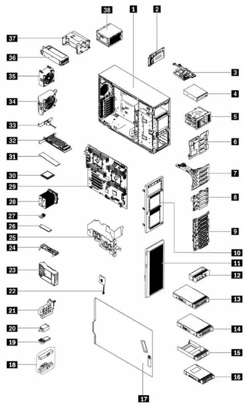
Figure 32. Server components
The parts listed in the following table are identified as one of the following:
- Tier 1 customer replaceable unit (CRU): Replacement of Tier 1 CRUs is your responsibility. If Lenovo installs a Tier 1 CRU at your request with no service agreement, you will be charged for the installation.
- Tier 2 customer replaceable unit: You may install a Tier 2 CRU yourself or request Lenovo to install it, at no additional charge, under the type of warranty service that is designated for your server.
- Field replaceable unit (FRU): FRUs must be installed only by trained service technicians.
- Consumable and Structural parts: Purchase and replacement of consumable and structural parts is your responsibility. If Lenovo acquires or installs a structural component at your request, you will be charged for the service.
Table 9. Parts listing
| Index | Description | Tier 1 CRU Tier 2 CRU FRU | Consumable and Structural parts | ||
| For more information about ordering the parts shown in Figure 32 “Server components” on page 50: http://datacentersupport.lenovo.com/us/en/products/servers/thinksystem/st550/7x09/parts | |||||
| 1 | Chassis | √ | |||
| 2 | Power interface board | √ | |||
| 3 | Front panel | √ | |||
| 4 | Optical drive / tape drive | √ | |||
| 5 | Expansion drive cage | √ | |||
| 6 | Backplane, four 3.5-inch hot-swap drives | √ | |||
| 7 | Backplate, four 3.5-inch simple-swap drives | √ | |||
| 8 | Backplane, four 2.5-inch hot-swap drives | √ | |||
| 9 | Backplane, eight 2.5-inch hot-swap drives | √ | |||
| 10 | Front bezel | √ | |||
| 11 | Front door | √ | |||
| 12 | Filler, 3.5-inch storage drive | √ | |||
| 13 | Storage drive, 3.5-inch, hot-swap | √ | |||
| 14 | Storage drive, 3.5-inch, simple-swap | √ | |||
| 15 | Filler, 2.5-inch storage drive | √ | |||
| 16 | Storage drive, 2.5-inch, hot-swap | √ | |||
| 17 | Server cover | √ | |||
| 18 | Rack latches | √ | |||
| 19 | Foot stand | √ | |||
| 20 | Intrusion switch | √ | |||
| 21 | PCIe adapter holder | √ | |||
| 22 | RAID super capacitor module | √ | |||
| 23 | PCIe adapter retainer | √ | |||
| 24 | M.2 backplane | √ | |||
| 25 | Air baffle | √ | |||
| 26 | M.2 drive | √ | |||
| 27 | TCM (only available in China) | √ | |||
| 28 | Heat sink | √ | |||
| 29 | System board | √ | |||
| 30 | CPU | √ | |||
| 31 | DIMM | √ | |||
| 32 | PCIe adapter | √ | |||
| 33 | Serial port module | √ | |||
| 34 | Front fan | √ | |||
| 35 | Rear fan | √ | |||
| 36 | Hot-swap power supply | √ | |||
| 37 | Hot-swap power supply cage | √ | |||
| 38 | Fixed power supply | √ | |||
Power cords
Several power cords are available, depending on the country and region where the server is installed.
To view the power cords that are available for the server:
- Go to:
http://lesc.lenovo.com
- In the Customize a Model pane:
a. Click Select Options/Parts for a Model.
b. Enter the machine type and model for your server.
- Click the Power tab to see all line cords.
Notes:
- For your safety, a power cord with a grounded attachment plug is provided to use with this product. To avoid electrical shock, always use the power cord and plug with a properly grounded outlet.
- Power cords for this product that are used in the United States and Canada are listed by Underwriter's Laboratories (UL) and certified by the Canadian Standards Association (CSA).
- For units intended to be operated at 115 volts: Use a UL-listed and CSA-certified cord set consisting of a minimum 18 AWG, Type SVT or SJT, three-conductor cord, a maximum of 15 feet in length and a parallel blade, grounding-type attachment plug rated 15 amperes, 125 volts.
- For units intended to be operated at 230 volts (U.S. use): Use a UL-listed and CSA-certified cord set consisting of a minimum 18 AWG, Type SVT or SJT, three-conductor cord, a maximum of 15 feet in length and a tandem blade, grounding-type attachment plug rated 15 amperes, 250 volts.
- For units intended to be operated at 230 volts (outside the U.S.): Use a cord set with a grounding-type attachment plug. The cord set should have the appropriate safety approvals for the country in which the equipment will be installed.
- Power cords for a specific country or region are usually available only in that country or region.
Chapter 3. Hardware replacement procedures
This section provides installation and removal procedures for all serviceable system components. Each component replacement procedure references any tasks that need to be performed to gain access to the component being replaced.
For more information about ordering parts:
http://datacentersupport.lenovo.com/us/en/products/servers/thinksystem/st550/7x09/parts
Note: If you replace a part, such as an adapter, that contains firmware, you might also need to update the firmware for that part. For more information about updating firmware, see “Firmware updates” on page 7.
Installation Guidelines
Before installing components in your server, read the installation guidelines.
Before installing optional devices, read the following notices carefully:
Attention: Prevent exposure to static electricity, which might lead to system halt and loss of data, by keeping static-sensitive components in their static-protective packages until installation, and handling these devices with an electrostatic-discharge wrist strap or other grounding system.
- Read the safety information and guidelines to ensure that you work safely.
- A complete list of safety information for all products is available at: http://thinksystem.lenovofiles.com/help/topic/safety_documentation/pdf_files.html
- "Handling static-sensitive devices" on page 56
- Make sure the components you are installing are supported by the server. For a list of supported optional components for the server, see http://www.lenovo.com/serverproven/.
- When you install a new server, download and apply the latest firmware. This will help ensure that any known issues are addressed, and that your server is ready to work with optimal performance. Go to ThinkSystem ST550 Drivers and Software to download firmware updates for your server.
Important: Some cluster solutions require specific code levels or coordinated code updates. If the component is part of a cluster solution, verify that the latest level of code is supported for the cluster solution before you update the code.
- It is good practice to make sure that the server is working correctly before you install an optional component.
- Keep the working area clean, and place removed components on a flat and smooth surface that does not shake or tilt.
-
Do not attempt to lift an object that might be too heavy for you. If you have to lift a heavy object, read the following precautions carefully:
-
Make sure that you can stand steadily without slipping.
- Distribute the weight of the object equally between your feet.
- Use a slow lifting force. Never move suddenly or twist when you lift a heavy object.
- To avoid straining the muscles in your back, lift by standing or by pushing up with your leg muscles.
- Make sure that you have an adequate number of properly grounded electrical outlets for the server, monitor, and other devices.
- Back up all important data before you make changes related to the disk drives.
- Have a small flat-blade screwdriver, a small Phillips screwdriver, and a T8 torx screwdriver available.
- You do not have to turn off the server to remove or install hot-swap power supplies or hot-plug USB devices. However, you must turn off the server before you perform any steps that involve removing or installing adapter cables, and you must disconnect the power source from the server before you perform any steps that involve removing or installing a DIMM.
- Blue on a component indicates touch points, where you can grip to remove a component from or install it in the server, open or close a latch, and so on.
- Orange on a component or an orange label on or near a component indicates that the component can be hot-swapped if the server and operating system support hot-swap capability, which means that you can remove or install the component while the server is still running. (Orange can also indicate touch points on hot-swap components.) See the instructions for removing or installing a specific hot-swap component for any additional procedures that you might have to perform before you remove or install the component.
- The Red strip on the drives, adjacent to the release latch, indicates that the drive can be hot-swapped if the server and operating system support hot-swap capability. This means that you can remove or install the drive while the server is still running.
Note: See the system specific instructions for removing or installing a hot-swap drive for any additional procedures that you might need to perform before you remove or install the drive.
- After finishing working on the server, make sure you reinstall all safety shields, guards, labels, and ground wires.
System reliability guidelines
Review the system reliability guidelines to ensure proper system cooling and reliability.
Make sure the following requirements are met:
- When the server comes with redundant power, a power supply must be installed in each power-supply bay.
- Adequate space around the server must be spared to allow server cooling system to work properly. Leave approximately 50 mm (2.0 in.) of open space around the front and rear of the server. Do not place any object in front of the fans.
- For proper cooling and airflow, refit the server cover before you turn the power on. Do not operate the server for more than 30 minutes with the server cover removed, for it might damage server components.
- Cabling instructions that come with optional components must be followed.
- A failed fan must be replaced within 48 hours since malfunction.
- A removed hot-swap drive must be replaced within two minutes after removal.
- A removed hot-swap power supply must be replaced within two minutes after removal.
- Every air baffle that comes with the server must be installed when the server starts (some servers might come with more than one air baffle). Operating the server with a missing air baffle might damage the processor.
- All processor sockets must contain either a socket cover or a processor with heat sink.
- When more than one processor is installed, fan population rules for each server must be strictly followed.
Handling static-sensitive devices
Review these guidelines before you handle static-sensitive devices to reduce the possibility of damage from electrostatic discharge.
Attention: Prevent exposure to static electricity, which might lead to system halt and loss of data, by keeping static-sensitive components in their static-protective packages until installation, and handling these devices with an electrostatic-discharge wrist strap or other grounding system.
- Limit your movement to prevent building up static electricity around you.
- Take additional care when handling devices during cold weather, for heating would reduce indoor humidity and increase static electricity.
- Always use an electrostatic-discharge wrist strap or other grounding system.
- While the device is still in its static-protective package, touch it to an unpainted metal surface on the outside of the server for at least two seconds. This drains static electricity from the package and from your body.
- Remove the device from the package and install it directly into the server without putting it down. If it is necessary to put the device down, put it back into the static-protective package. Never place the device on the server or on any metal surface.
- When handling a device, carefully hold it by the edges or the frame.
- Do not touch solder joints, pins, or exposed circuitry.
- Keep the device from others' reach to prevent possible damages.
Front door replacement
Use this information to remove and install the front door.
Note: This section applies only to server models that have a front door installed.
Remove the front door
Use this information to remove the front door.

Read the Installation Guidelines
To remove the front door, complete the following steps:
Watch the procedure. A video of the removal process is available:
- Youtube: https://www.youtube.com/playlist?list=PLYV5R7hVcs-Acsjj4tU79GzKnWG316BYn
- Youku: http://list.youku.com/albumlist/show/id_50483452

natural_image
Diagram of an open server rack cabinet with internal racks and ventilation slots (no text or labels)Figure 33. Front door removal
Step 1. Open the front door.
Step 2. Lift the front door slightly upward until you can completely remove it.
Install the front door
Use this information to install the front door.

Read the
Installation
Guidelines
Before installing the front door, if the server comes with rubber blocks to cover the holes for installing the front door, remove the rubber blocks first. Store the rubber blocks in case that you later remove the front door and need the rubber blocks to cover the holes in the front bezel.
To install the front door, complete the following steps:
Watch the procedure. A video of the installation process is available:
- Youtube: https://www.youtube.com/playlist?list=PLYV5R7hVcs-Acsjj4tU79GzKnWG316BYn
- Youku: http://list.youku.com/albumlist/show/id_50483452

natural_image
Diagram of a server rack cabinet with two open doors showing internal components (no text or labels)Figure 34. Front door installation
Step 1. Align the two hooks on the front door with the corresponding holes in the front bezel. Then, move the front door inward and then pull it slightly downward until it is secured in place by the hooks.
Step 2. Close the front door.
Foot stands replacement
Use this information to remove and install the foot stands.
Note: This section applies only to server models that have foot stands installed.
Remove the foot stands
Use this information to remove the foot stands.

Read the Installation Guidelines
To remove the foot stands, complete the following steps:
Watch the procedure. A video of the removal process is available:
- Youtube: https://www.youtube.com/playlist?list=PLYV5R7hVcs-Acsjj4tU79GzKnWG316BYn
- Youku: http://list.youku.com/albumlist/show/id_50483452
Step 1. Lay the server on its side for easier operation.
Step 2. For each foot stand, press the release tab and then pivot the foot stand outward to remove it from the chassis.
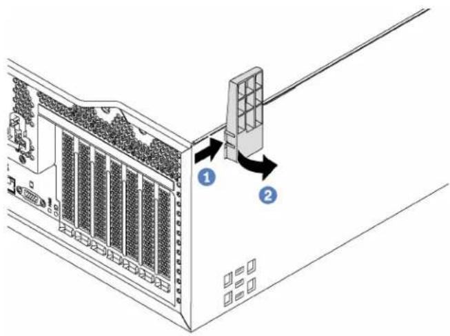
Figure 35. Foot stand removal
Install the foot stands
Use this information to install the foot stands.

Read the Installation Guidelines
To install the foot stands, complete the following steps:
Watch the procedure. A video of the installation process is available:
- Youtube: https://www.youtube.com/playlist?list=PLYV5R7hVcs-Acsjj4tU79GzKnWG316BYn
- Youku: http://list.youku.com/albumlist/show/id_50483452
Step 1. Lay the server on its side for easier operation.
Step 2. For each foot stand, carefully insert the two tabs on the foot stand into the corresponding holes in the chassis. Then, pivot the foot stand inward until the other side clicks into place.
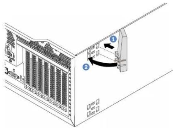
Figure 36. Foot stand installation
Important: To help the server stand steadily, ensure that the foot stands are installed outward as shown in "Front view" on page 13.
Rack latch replacement
Use this information to remove and install a rack latch of the server in rack form factor.
Note: This section applies only to server models that have the rack latches installed.
Remove a rack latch
Use this information to remove a rack latch.

Read the Installation Guidelines
Before removing a rack latch, if the server is installed in a rack, remove the server from the rack and place it on a stable work surface.
To remove a rack latch, complete the following steps:
Watch the procedure. A video of the removal process is available:
- Youtube: https://www.youtube.com/playlist?list=PLYV5R7hVcs-Acsjj4tU79GzKnWG316BYn
- Youku: http://list.youku.com/albumlist/show/id_50483452
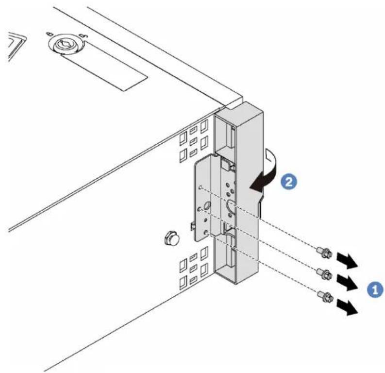
Figure 37. Rack latch removal
Step 1. Remove the screws that secure the rack latch.
Step 2. Pivot the rack latch as shown until the rack latch is disengaged from the chassis. Then, remove the rack latch from the chassis.
If you are instructed to return the old rack latch, follow all packaging instructions and use any packaging materials that are provided.
Install a rack latch
Use this information to install a rack latch.

To install a rack latch, complete the following steps:
Watch the procedure. A video of the installation process is available:
- Youtube: https://www.youtube.com/playlist?list=PLYV5R7hVcs-Acsjj4tU79GzKnWG316BYn
• Youku: http://list.youku.com/albumlist/show/id_50483452

Figure 38. Rack latch installation
Step 1. Insert the rack latch tab into the hole in the chassis as shown. Then, align the holes in the rack latch with the corresponding holes in the chassis underside.
Step 2. Install the screws to secure the rack latch.
After installing the rack latch, reinstall the server to the rack.
Server cover replacement
Use this information to remove and install the server cover.
S033

CAUTION:
Hazardous energy present. Voltages with hazardous energy might cause heating when shorted with metal, which might result in spattered metal, burns, or both.
S014

CAUTION:
Hazardous voltage, current, and energy levels might be present. Only a qualified service technician is authorized to remove the covers where the following label is attached.
Remove the server cover
Use this information to remove the server cover.

Read the Installation Guidelines

Power Off the server for this task

ATTENTION: Static Sensitive Device Ground package before opening
To remove the server cover, complete the following steps:
Watch the procedure. A video of the removal process is available:
- Youtube: https://www.youtube.com/playlist?list=PLYV5R7hVcs-Acsjj4tU79GzKnWG316BYn
- Youku: http://list.youku.com/albumlist/show/id_50483452

Figure 39. Server cover removal
Step 1. Use the key attached on the rear of the server to turn the cover lock to the open position.
Step 2. Slide the server cover toward the rear of the server until the server cover is disengaged from the chassis. Then, lift the server cover off the chassis and place it on a flat clean surface.
Attention: For proper cooling and airflow, install the server cover before turning on the server. Operating the server with the server cover removed might damage server components.
Install the server cover
Use this information to install the server cover.

Read the Installation Guidelines

Power Off
the server
for this task

ATTENTION: Static Sensitive Device Ground package before opening
Before installing the server cover:
- Ensure that all adapters and other components are installed and seated correctly and that you have not left loose tools or parts inside the server.
- Ensure that all internal cables are correctly routed. See "Internal cable routing" on page 27.
- If you are installing a new server cover, attach the service label to the inside of the new server cover first if necessary.
Note: A new server cover comes without a service label attached. If you need a service label, order it together with the new server cover. The service label is free of charge.
To install the server cover, complete the following steps:
Watch the procedure. A video of the installation process is available:
- Youtube: https://www.youtube.com/playlist?list=PLYV5R7hVcs-Acsjj4tU79GzKnWG316BYn
- Youku: http://list.youku.com/albumlist/show/id_50483452

Figure 40. Server cover installation
Step 1. Lower the server cover onto the chassis until all tabs on both sides of the server cover engage the chassis. Then, slide the server cover toward the front of the chassis until the server cover stops and the front edge of the cover aligns with the edge of the front bezel.
Note: Before you slide the cover forward, ensure that all the tabs of the cover engage the chassis correctly. If all the tabs do not engage the chassis correctly, it will be very difficult to remove the cover later.
Step 2. Use the key to turn the cover lock to the locked position.
After installing the top cover, reconnect external cables if necessary.
RAID super capacitor module replacement
Use this information to remove and install the RAID super capacitor module.
Note: This topic applies only to server models that have RAID super capacitor modules installed.
The RAID super capacitor module protects the cache memory on the installed RAID adapter. You can purchase a RAID super capacitor module from Lenovo.
For a list of supported options, see: http://www.lenovo.com/serverproven/
Remove a RAID super capacitor module
Use this information to remove a RAID super capacitor module on the air baffle.

Read the Installation Guidelines

Power Off
the server
for this task

ATTENTION: Static Sensitive Device Ground package before opening
Before removing a RAID super capacitor module:
- If the server is installed in a rack, extend the server from the rack.
- Remove the server cover. See "Remove the server cover" on page 63.
To remove a RAID super capacitor module, complete the following steps:
Watch the procedure. A video of the removal process is available:
- Youtube: https://www.youtube.com/playlist?list=PLYV5R7hVcs-Acsjj4tU79GzKnWG316BYn
- Youku: http://list.youku.com/albumlist/show/id_50483452
Step 1. Disconnect the RAID super capacitor module from the extension cable.
Step 2. Gently press the tab on the air baffle and then remove the RAID super capacitor module from the air baffle as shown.

Figure 41. RAID super capacitor module removal
If you are instructed to return the old RAID super capacitor module, follow all packaging instructions and use any packaging materials that are provided.
Install a RAID super capacitor module
Use this information to install a RAID super capacitor module on the air baffle.

Read the Installation Guidelines
Power Off
the server
for this task

ATTENTION: Static Sensitive Device
ground package before opening
To install a RAID super capacitor module, complete the following steps:
Watch the procedure. A video of the installation process is available:
- Youtube: https://www.youtube.com/playlist?list=PLYV5R7hVcs-Acsjj4tU79GzKnWG316BYn
- Youku: http://list.youku.com/albumlist/show/id_50483452
Step 1. Touch the static-protective package that contains the new RAID super capacitor module to any unpainted surface on the outside of the server. Then, take the new RAID super capacitor module out of the package and place it on a static-protective surface.
Step 2. Insert one end of the RAID super capacitor module into the slot of the air baffle. Then, press down the other end of the RAID super capacitor module until it snaps in place.

Figure 42. RAID super capacitor module installation
Step 3. Connect the RAID super capacitor module to the extension cable.
After installing the RAID super capacitor module, complete the parts replacement. See “Complete the parts replacement” on page 170.
Air baffle replacement
Use this information to remove and install the air baffle.
S033

CAUTION:
Hazardous energy present. Voltages with hazardous energy might cause heating when shorted with metal, which might result in spattered metal, burns, or both.
S017

CAUTION:
Hazardous moving fan blades nearby.
Remove the air baffle
Use this information to remove the air baffle.

Before removing the air baffle:
- If the server is installed in a rack, extend the server from the rack.
- Remove the server cover. See "Remove the server cover" on page 63.
- If there is a RAID super capacitor module installed on the air baffle, disconnect the RAID super capacitor module cable first.
To remove the air baffle, complete the following step:
Watch the procedure. A video of the removal process is available:
- Youtube: https://www.youtube.com/playlist?list=PLYV5R7hVcs-Acsjj4tU79GzKnWG316BYn
- Youku: http://list.youku.com/albumlist/show/id_50483452
Step 1. Lift up the front end of the air baffle until the rear end of the air baffle is disengaged from the chassis. Then, remove the air baffle out of the chassis.
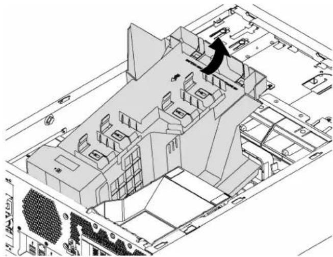
natural_image
Architectural floor plan of a computer room showing internal components and ventilation ducts (no text or labels)Figure 43. Air baffle removal
Attention: For proper cooling and airflow, install the air baffle before you turn on the server. Operating the server with the air baffle removed might damage server components.
Install the air baffle
Use this information to install the air baffle.

Before installing the air baffle, ensure that all cables inside the server have been properly routed so that they will not interfere with the air baffle.
To install the air baffle, complete the following steps:
Watch the procedure. A video of the installation process is available:
- Youtube: https://www.youtube.com/playlist?list=PLYV5R7hVcs-Acsjj4tU79GzKnWG316BYn
- Youku: http://list.youku.com/albumlist/show/id_50483452
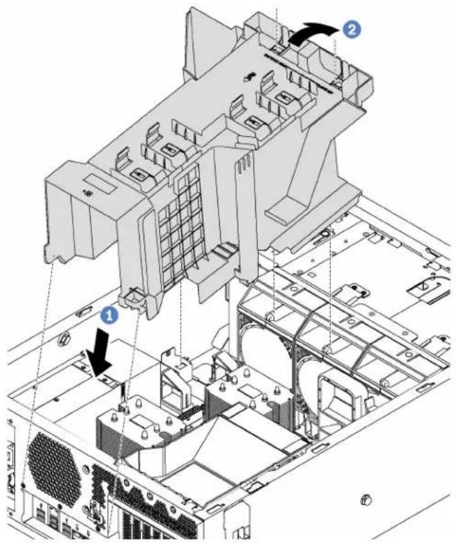
Figure 44. Air baffle installation
Step 1. Carefully insert the rear end of the air baffle into the chassis.
Step 2. Press the front end of the air baffle downward until it snaps into place.
After installing the air baffle:
-
If there is a RAID super capacitor module installed on the air baffle, connect it to the RAID adapter with the extension cable that comes with the RAID super capacitor module.
-
Complete the parts replacement. See "Complete the parts replacement" on page 170.
Use this information to remove and install a front fan.
S033

CAUTION:
Hazardous energy present. Voltages with hazardous energy might cause heating when shorted with metal, which might result in spattered metal, burns, or both.
S009

CAUTION:
To avoid personal injury, disconnect the fan cables before removing the fan from the device.
S002

CAUTION:
Make sure all power cords are disconnected from system when reading in this manual and the following step is required to complete: Disconnect the power cords and all external cables from the rear of the enclosure.
Remove a front fan
Use this information to remove a front fan.

Read the Installation Guidelines

Power Off the server for this task

ATTENTION: Static Sensitive Device Ground package before opening
Before removing a front fan:
- If the server is installed in a rack, extend the server from the rack.
- Remove the server cover. See "Remove the server cover" on page 63.
- Remove the air baffle. See "Remove the air baffle" on page 67.
To remove a front fan, complete the following steps:
Watch the procedure. A video of the removal process is available:
- Youtube: https://www.youtube.com/playlist?list=PLYV5R7hVcs-Acsjj4tU79GzKnWG316BYn
- Youku: http://list.youku.com/albumlist/show/id_50483452
Step 1. Disconnect the fan cable from the system board.
Step 2. Press down the release tab and pivot the front fan as shown. Then, take the front fan out of the chassis.
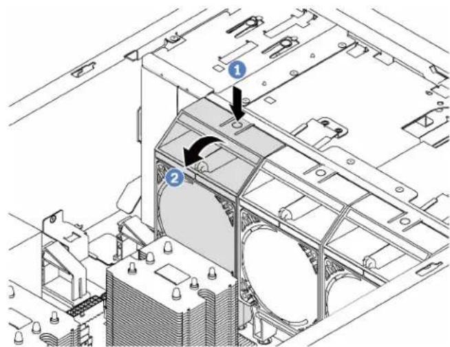
Figure 45. Front fan removal
After removing the front fan:
- Install either a new front fan or a fan filler for proper air flow. See "Install a front fan" on page 71.
- If you are instructed to return the old front fan, follow all packaging instructions and use any packaging materials that are provided.
Install a front fan
Use this information to install a front fan.

Read the Installation Guidelines

Power Off
the server
for this task

ATTENTION: Static Sensitive Device Ground package before opening
To install a front fan, complete the following steps:
Watch the procedure. A video of the installation process is available:
- Youtube: https://www.youtube.com/playlist?list=PLYV5R7hVcs-Acsjj4tU79GzKnWG316BYn
- Youku: http://list.youku.com/albumlist/show/id_50483452
Step 1. Touch the static-protective package that contains the new front fan to any unpainted surface on the outside of the server. Then, take the new front fan out of the package and place it on a static-protective surface.
Step 2. Align the pins on the front fan with the corresponding holes in the chassis. Then, pivot the front fan forward until it snaps into place.

Figure 46. Front fan installation
Step 3. Connect the front fan cable to the corresponding fan connector on the system board. For the location of the system fan connectors, see "System board components" on page 24.
After installing the front fan, complete the parts replacement. See "Complete the parts replacement" on page 170.
Rear fan replacement
Use this information to remove and install the rear fan.
Note: This section applies only to server models that have the rear fan installed.
S033

CAUTION: Hazardous energy present. Voltages with hazardous energy might cause heating when shorted with metal, which might result in spattered metal, burns, or both.
S009

CAUTION: To avoid personal injury, disconnect the fan cables before removing the fan from the device.
S002
CAUTION:
Make sure all power cords are disconnected from system when reading in this manual and the following step is required to complete: Disconnect the power cords and all external cables from the rear of the enclosure.
Remove the rear fan
Use this information to remove the rear fan.

Read the Installation Guidelines

Power Off
the server
for this task

ATTENTION: Static Sensitive Device Ground package before opening
Before removing the rear fan:
- If the server is installed in a rack, extend the server from the rack.
- Remove the server cover. See "Remove the server cover" on page 63.
- Remove the air baffle. See "Remove the air baffle" on page 67.
To remove the rear fan, complete the following steps:
Watch the procedure. A video of the removal process is available:
- Youtube: https://www.youtube.com/playlist?list=PLYV5R7hVcs-Acsjj4tU79GzKnWG316BYn
- Youku: http://list.youku.com/albumlist/show/id_50483452
Step 1. Disconnect the fan cable from the system board.
Step 2. Press down the release tab and pivot the rear fan away from the chassis. Then, take the rear fan out of the chassis.
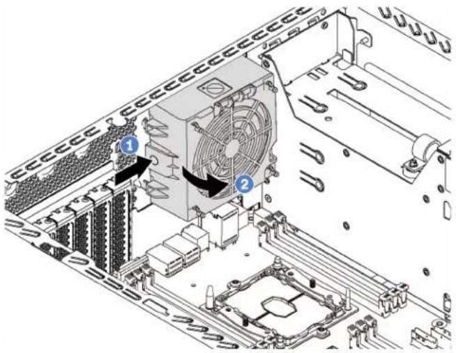
Figure 47. Rear fan removal
After removing the rear fan:
-
Install a new rear fan to replace the old one. See "Install the rear fan" on page 74.
-
If you are instructed to return the old rear fan, follow all packaging instructions and use any packaging materials that are provided.
Install the rear fan
Use this information to install the rear fan.

Read the Installation Guidelines

Power Off
the server
for this task

ATTENTION: Static Sensitive Device Ground package before opening
To install the rear fan, complete the following steps:
Watch the procedure. A video of the installation process is available:
- Youtube: https://www.youtube.com/playlist?list=PLYV5R7hVcs-Acsjj4tU79GzKnWG316BYn
- Youku: http://list.youku.com/albumlist/show/id_50483452
Step 1. Touch the static-protective package that contains the new rear fan to any unpainted surface on the outside of the server. Then, take the new rear fan out of the package and place it on a static-protective surface.
Step 2. Align the pins on the rear fan with the corresponding holes in the chassis. Then, pivot the rear fan toward the rear of the chassis until it snaps into place.

Figure 48. Rear fan installation
Step 3. Connect the rear fan cable to the system fan 4 connector on the system board. For the location of the system fan 4 connector, see "System board components" on page 24.
After installing the rear fan, complete the parts replacement. See "Complete the parts replacement" on page 170.
PCIe adapter holder replacement
Use this information to remove and install the PCIe adapter holder, which helps to hold the full-length PCIe adapters.
Remove the PCIe adapter holder
Use this information to remove the PCIe adapter holder.

Read the Installation Guidelines
Power Off
the server
for this task
Before removing the PCIe adapter holder:
- If the server is installed in a rack, extend the server from the rack.
- Remove the server cover. See "Remove the server cover" on page 63.
-
Remove the air baffle. See "Remove the air baffle" on page 67.
-
If a full-length PCIe adapter is held by the PCIe adapter holder, remove the full-length PCIe adapter first. See "Remove a PCIe adapter" on page 113.
To remove the PCIe adapter holder, complete the following steps:
Watch the procedure. A video of the removal process is available:
- Youtube: https://www.youtube.com/playlist?list=PLYV5R7hVcs-Acsjj4tU79GzKnWG316BYn
- Youku: http://list.youku.com/albumlist/show/id_50483452

Figure 49. PCIe adapter holder removal
Step 1. Press the tab.
Step 2. Remove the PCIe adapter holder in the direction as shown.
Install the PCIe adapter holder
Use this information to install the PCIe adapter holder.

Read the Installation Guidelines

Power Off
the server
for this task
To install the PCIe adapter holder, complete the following steps:
Watch the procedure. A video of the installation process is available:
- Youtube: https://www.youtube.com/playlist?list=PLYV5R7hVcs-Acsjj4tU79GzKnWG316BYn
- Youku: http://list.youku.com/albumlist/show/id_50483452

natural_image
Technical line drawing of an industrial cooling unit with cooling fan and cooling tower (no text or labels)Figure 50. PCIe adapter holder installation
Step 1. Insert the PCIe-adapter-holder post into the corresponding recess in the chassis.
Step 2. Secure the three notches on the PCIe adapter holder with the three mounting studs on the chassis.
Step 3. Secure the PCIe-adapter-holder tab with the corresponding hole in the chassis.
After installing the PCIe adapter holder:
-
If you have removed a full-length PCIe adapter, reinstall it. See "Install a PCIe adapter" on page 114.
-
Complete the parts replacement. See "Install the server cover" on page 170.
Front bezel replacement
Use this information to remove and install the front bezel.
Remove the front bezel
Use this information to remove the front bezel.

Read the Installation Guidelines

Power Off
the server
for this task
Before removing the front bezel:
- If the server is installed in a rack, remove the server from the rack. Then, remove the rack latches. See "Remove a rack latch" on page 61.
- If your server has the front door installed, remove the front door. See "Remove the front door" on page 57.
- Remove the server cover. See "Remove the server cover" on page 63.
To remove the front bezel, complete the following step:
Watch the procedure. A video of the removal process is available:
- Youtube: https://www.youtube.com/playlist?list=PLYV5R7hVcs-Acsjj4tU79GzKnWG316BYn
- Youku: http://list.youku.com/albumlist/show/id_50483452
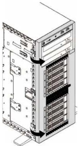
natural_image
Diagram of a server rack with multiple drive bays and a central tower, showing internal components without any text or labels.Figure 51. Front bezel removal
Step 1. Pivot the two plastic tabs outward until you can remove the front bezel completely.
Install the front bezel
Use this information to install the front bezel.

Read the Installation Guidelines

Power Off
the server
for this task
To install the front bezel, complete the following step:
Watch the procedure. A video of the installation process is available:
- Youtube: https://www.youtube.com/playlist?list=PLYV5R7hVcs-Acsjj4tU79GzKnWG316BYn
- Youku: http://list.youku.com/albumlist/show/id_50483452

natural_image
Technical diagram of a server rack with multiple drive bays and ventilation ducts, showing internal components without any text or labels.
natural_image
Technical line drawing of a server rack with internal components and mounting hardware (no text or symbols)Figure 52. Front bezel installation
Step 1. Align the three plastic tabs with the corresponding holes in the chassis. Then, pivot the front bezel inward until it snaps into place.
After installing the front bezel, complete the parts replacement. See “Complete the parts replacement” on page 170.
Front panel replacement
Use this information to remove and install the front panel.
Remove the front panel
Use this information to remove the front panel.

Read the Installation Guidelines

Power Off
the server
for this task

ATTENTION: Static Sensitive Device Ground package before opening
Before removing the front panel:
- If the server is installed in a rack, extend the server from the rack.
- Remove the server cover. See "Remove the server cover" on page 63.
- Remove the air baffle. See "Remove the air baffle" on page 67.
- Remove the front fans. See "Remove a front fan" on page 70.
- Remove the PCIe adapter holder. See "Remove the PCIe adapter holder" on page 75.
To remove the front panel, complete the following steps:
Watch the procedure. A video of the removal process is available:
- Youtube: https://www.youtube.com/playlist?list=PLYV5R7hVcs-Acsjj4tU79GzKnWG316BYn
- Youku: http://list.youku.com/albumlist/show/id_50483452
Step 1. Disconnect the front panel cables from the system board. For detailed cable routing, see "Front panel" on page 29.
Step 2. Press the release tab in the direction as shown and then pull the front panel out of the dedicated bay.

Figure 53. Front panel removal
Step 3. Take the front panel out of the chassis.
Note: Adjust any cables that might impede your operation.
If you are instructed to return the old front panel, follow all packaging instructions and use any packaging materials that are provided.
Install the front panel
Use this information to install the front panel.

Read the Installation Guidelines
Power Off
the server
for this task

ATTENTION: Static Sensitive Device Ground package before opening
To install the front panel, complete the following steps:
Watch the procedure. A video of the installation process is available:
- Youtube: https://www.youtube.com/playlist?list=PLYV5R7hVcs-Acsjj4tU79GzKnWG316BYn
- Youku: http://list.youku.com/albumlist/show/id_50483452
Step 1. Touch the static-protective package that contains the new front panel to any unpainted metal surface on the server. Then, take the new front panel from the package and place it on a static-protective surface.
Step 2. Insert the front panel into the dedicated bay as shown. Then, carefully slide the front panel into the bay until it snaps into place.

natural_image
Technical line drawing of an electronic device interior showing internal components and a directional arrow (no text or symbols)Figure 54. Front panel installation
Step 3. Carefully route the two front panel cables from the secured front panel along the back side of the storage drive bays. Manage the cables so that they are secured by the clips under the front fans or fan fillers.
Important: The front panel cables and all other cables in this space must be secured by the clips so that it is possible to install the fans or fan fillers over the cables.
Step 4. Connect the front panel cables to the corresponding connectors on the system board. For more information, see "Front panel" on page 29.
After installing the front panel, complete the parts replacement. See "Complete the parts replacement" on page 170.
Optical drive or tape drive replacement
Use this information to remove and install the optical drive or tape drive.
Note: This section applies only to server models that have an optical drive or a tape drive installed.
S006

CAUTION:
When laser products (such as CD-ROMs, DVD drives, fiber optic devices, or transmitters) are installed, note the following:
- Do not remove the covers. Removing the covers of the laser product could result in exposure to hazardous laser radiation. There are no serviceable parts inside the device.
- Use of controls or adjustments or performance of procedures other than those specified herein might result in hazardous radiation exposure.
S007

CAUTION:
This product contains a Class 1M laser. Do not view directly with optical instruments.
S008


DANGER
Some laser products contain an embedded Class 3A or Class 3B laser diode. Note the following. Laser radiation when open. Do not stare into the beam, do not view directly with optical instruments, and avoid direct exposure to the beam.
Remove an optical drive or a tape drive
Use this information to remove an optical drive or a tape drive.

Read the Installation Guidelines
Power Off the server for this task

ATTENTION: Static Sensitive Device Ground package before opening
Note: The following illustrations are based on the scenario that you remove an optical drive. The procedure is similar for removing a tape drive.
Before removing an optical drive or a tape drive:
- If the server is installed in a rack, extend the server from the rack.
- Remove the server cover. See "Remove the server cover" on page 63.
- If your server has the front door installed, remove the front door. See "Remove the front door" on page 57.
- Remove the front bezel. See "Remove the front bezel" on page 76.
- Remove the air baffle. See "Remove the air baffle" on page 67.
- If the Fan 3 impedes your access to the optical drive or tape drive, remove it. See "Remove a front fan" on page 70.
To remove an optical drive or a tape drive, complete the following steps:
Watch the procedure. A video of the removal process is available:
- Youtube: https://www.youtube.com/playlist?list=PLYV5R7hVcs-Acsjj4tU79GzKnWG316BYn
- Youku: http://list.youku.com/albumlist/show/id_50483452
Step 1. Disconnect the cables from the rear of the optical drive or the tape drive.
Step 2. Press and hold the release tab and push the optical drive or the tape drive forward to remove it from the chassis.
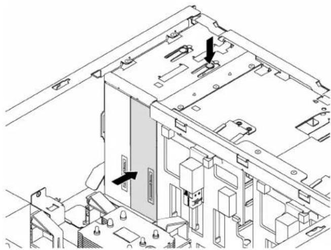
natural_image
Technical line drawing of a computer tower internal structure with no visible text or symbolsFigure 55. Optical drive removal
After removing an optical drive or a tape drive:
- Install a new optical drive or tape drive, or install a filler to cover the drive bay. To install a new optical drive or a tape drive, see "Install an optical drive or a tape drive" on page 83. To install a filler, complete the following steps:
a. Insert the filler to the vacant drive bay.

natural_image
Technical line drawing of a server rack with an internal panel and directional arrow (no text or symbols)Figure 56. Drive bay filler installation
b. Install the cover of the drive bay filler to the front bezel. Then, install the front bezel to the chassis.

natural_image
Technical line drawings of server rack and rack unit components (no text or symbols)Figure 57. Drive-bay-filler cover installation
- Remove the retainer from the removed optical drive or tape drive, and then install the retainer to the chassis.
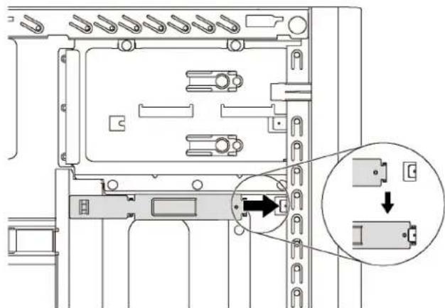
natural_image
Technical diagram of a computer RAM module with an inset showing a close-up of the internal components (no text or symbols present)Figure 58. Drive retainer installation
- If you are instructed to return the old optical drive or tape drive, follow all of the packaging instructions and use any packaging materials that are provided.
Install an optical drive or a tape drive
Use this information to install an optical drive or a tape drive.

Read the Installation Guidelines

Power Off
the server
for this task

ATTENTION: Static Sensitive Device Ground package before opening
Note: The following illustrations are based on the scenario that you install an optical drive. The procedure is similar for installing a tape drive.
Before installing an optical drive or a tape drive:
- If the drive bay is covered by a filler, remove it first. Store the filler in case that you later remove the optical drive or the tape drive and need the filler to cover the place. To remove the filler, complete the following steps:
a. Remove the front bezel and then remove the cover of the drive bay filler from the front bezel.

natural_image
Technical illustration of server rack components showing front and side views (no text or symbols)Figure 59. Drive-bay-filler cover removal
b. Remove the drive bay filler out of the chassis.

natural_image
Technical line drawing of a server rack unit with multiple drive bays and ventilation slots (no text or labels)Figure 60. Drive bay filler removal
- Touch the static-protective package that contains the new optical drive or tape drive to any unpainted surface on the outside of the server. Then, take the new optical drive or tape drive out of the package and place it on a static-protective surface.
To install an optical drive or a tape drive, complete the following steps:
Watch the procedure. A video of the installation process is available:
- Youtube: https://www.youtube.com/playlist?list=PLYV5R7hVcs-Acsjj4tU79GzKnWG316BYn
- Youku: http://list.youku.com/albumlist/show/id_50483452
Step 1. Remove the retainer from the chassis.

natural_image
Technical diagram of a computer RAM module with no visible text or symbolsFigure 61. Drive retainer removal
Step 2. Install the retainer on only the left side of the optical drive or tape drive.
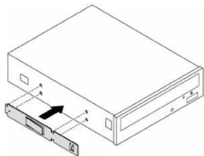
natural_image
Diagram of a computer drive with an attached physical component, showing internal components and an arrow indicating motion (no text or symbols present)Figure 62. Optical drive retainer installation
Step 3. Hold the optical drive or tape drive in correct orientation and then slide it into the drive bay until it snaps into position.

natural_image
Technical line drawing of a server rack with multiple drive bays and an upper stack (no text or symbols)Figure 63. Optical drive installation
Step 4. Connect the power cable and the signal cable to the rear of the new optical drive or tape drive. For more information about the cable routing, see "Optical drive" on page 30 and "Tape drive" on page 31.
After installing the optical drive or tape drive, complete the parts replacement. See “Complete the parts replacement” on page 170.
Simple-swap drive replacement
Use this information to remove and install a simple-swap drive.
Notes:
- This section applies only to server models that support simple-swap drives.
- The term “simple-swap drive” refers to all the supported types of simple-swap hard disk drives and simple-swap solid-state drives.
- You must turn off the server before installing or removing a simple-swap drive to avoid data loss.
- Use any documentation that comes with the drive and follow those instructions in addition to the instructions in this topic. Ensure that you have all the cables and other equipment that are specified in the documentation that comes with the drive.
- The electromagnetic interference (EMI) integrity and cooling of the server are protected by having all drive bays covered or occupied. The vacant bays are either covered by an EMI-protective panel or occupied by drive fillers. When installing a drive, save the removed drive filler in case that you later remove the drive and need the drive filler to cover the place.
Remove a simple-swap drive
Use this information to remove a simple-swap drive.

Read the Installation Guidelines

Power Off the server for this task

ATTENTION: Static Sensitive Device Ground package before opening
Before removing a simple-swap drive:
- Ensure that you have back up data on your drive, especially if it is part of a RAID array.
- Before you make changes to drives, drive backplanes, or drive cables, back up all important data that is stored on the drives.
- Before you remove any component of a RAID array, back up all RAID configuration information.
- If the server is installed in a rack, extend the server from the rack.
- If the server has the front door installed, open it.
To remove a simple-swap drive, complete the following steps:
Watch the procedure. A video of the removal process is available:
- Youtube: https://www.youtube.com/playlist?list=PLYV5R7hVcs-Acsjj4tU79GzKnWG316BYn
- Youku: http://list.youku.com/albumlist/show/id_50483452
Step 1. Use a screwdriver to turn the handle lock ☐ to the unlocked position. Then, the tray handle opens automatically.
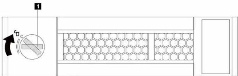
natural_image
Technical diagram of a mechanical or electrical component with hexagonal lattice structure and directional arrows (no text or symbols)Figure 64. Opening the tray handle of a 3.5-inch simple-swap drive
Step 2. Pull the tray handle and carefully slide the simple-swap drive out of the drive bay.

natural_image
Technical line drawing of a mechanical device with internal channels and a black arrow indicating a component (no text or symbols present)Figure 65. 3.5-inch simple-swap drive removal
After removing a simple-swap drive:
- Install a new drive or install the drive filler to cover the drive bay. See "Install a simple-swap drive" on page 87.
Note: To ensure that there is adequate system cooling, do not operate the server for more than two minutes without either a drive or a drive filler installed in each bay.
- If you are instructed to return the simple-swap drive, follow all packaging instructions and use any packaging materials that are provided.
Install a simple-swap drive
Use this information install a simple-swap drive.


The following notes describe the type of drives that your server supports and other information that you must consider when you install a drive.
- For a complete list of supported optional devices for the server, see: http://www.lenovo.com/serverproven/
- The drive bays are numbered to indicate the installation order (starting from number "0"). Follow the installation order when you install a drive. See "Front view" on page 13.
- You can mix drives of different types, different sizes, and different capacities in one system, but not in one RAID array. The following order is recommended when installing the drives:
- Drive type priority: SSD, SATA HDD
- Drive capacity priority: the lowest capacity first
- The drives in a single RAID array must be the same type, same size, and same capacity.
Before installing a simple-swap drive:
- If the drive bay has a drive filler installed, remove it. Keep the drive filler in a safe place for future use.
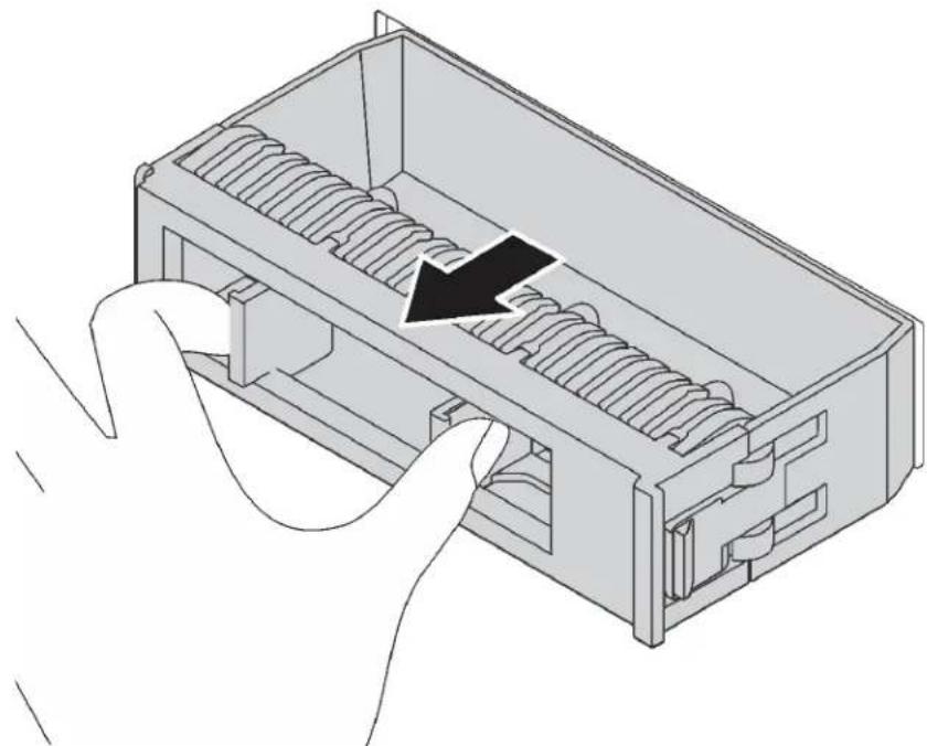
natural_image
Illustration of a hand inserting into a device into a rectangular housing with internal spring-like slots (no text or symbols)Figure 66. 3.5-inch drive filler removal
- Touch the static-protective package that contains the new simple-drive to any unpainted surface on the outside of the server. Then, take the new simple-swap drive out of the package and place it on a static-protective surface.
To install a simple-swap drive, complete the following steps:
Watch the procedure. A video of the installation process is available:
- Youtube: https://www.youtube.com/playlist?list=PLYV5R7hVcs-Acsjj4tU79GzKnWG316BYn

Figure 67. 3.5-inch simple-swap drive installation
Step 1. Ensure that the tray handle is in the open position. Align the drive with the guide rails in the bay. Then, gently push the drive into the bay until the drive stops.
Step 2. Close the tray handle to lock the drive in place.
After installing a simple-swap drive:
1. Continue to install additional simple-swap drives if necessary.
2. Complete the parts replacement. See "Completing the parts replacement" on page 170.
3. Check the simple-swap-drive activity LED on the front panel to verify that the drive is operating correctly.
| Simple-swap-drive activity LED | Color | Description |
| Solid on Green | The simple-swap drive is active. | |
| Off | None The | simple-swap drive is not active. |
- If the server has the front door installed, close it.
Hot-swap drive replacement
Use this information to remove and install a hot-swap drive. You can remove or install a hot-swap drive without turning off the server, which helps you avoid significant interruption to the operation of the system.
Notes:
- This section applies only to server models that support hot-swap drives.
- The term “hot-swap drive” refers to all the supported types of hot-swap hard disk drives, hot-swap solid-state drives, and hot-swap NVMe drives.
- Use any documentation that comes with the drive and follow those instructions in addition to the instructions in this topic. Ensure that you have all the cables and other equipment that are specified in the documentation that comes with the drive.
- The electromagnetic interference (EMI) integrity and cooling of the server are protected by having all drive bays covered or occupied. The vacant bays are either covered by an EMI-protective panel or occupied by drive fillers. When installing a drive, save the removed drive filler in case that you later remove the drive and need the drive filler to cover the place.
Remove a hot-swap drive
Use this information to remove a hot-swap drive.

Read the Installation Guidelines

ATTENTION: Static Sensitive Device
around package before opening
Before removing a hot-swap drive:
-
Ensure that you have back up data on your drive, especially if it is part of a RAID array.
-
Before you make changes to drives, RAID adapters, drive backplanes, or drive cables, back up all important data that is stored on the drives.
-
Before you remove any component of a RAID array, back up all RAID configuration information.
-
If the server is installed in a rack, extend the server from the rack.
-
If the server has the front door installed, open it.
To remove a hot-swap drive, complete the following steps:
Watch the procedure. A video of the removal process is available:
- Youtube: https://www.youtube.com/playlist?list=PLYV5R7hVcs-Acsjj4tU79GzKnWG316BYn
- Youku: http://list.youku.com/albumlist/show/id_50483452
Step 1. Slide the release latch to open the tray handle.

natural_image
Diagram of a room layout with hexagonal pattern and directional arrow (no text or symbols)Figure 68. Opening the tray handle
Step 2. Grasp the tray handle and carefully slide the drive out of the drive bay.

natural_image
Technical illustration of a mechanical device with internal channels and a black arrow indicating a specific component (no text or symbols present)Figure 69. Hot-swap drive removal
After removing a hot-swap drive:
- Install a new drive or install the drive filler to cover the drive bay. See "Install a hot-swap drive" on page 91.
Attention: To ensure that there is adequate system cooling, do not operate the server for more than two minutes without either a drive or a drive filler installed in each bay.
- If you are instructed to return the old hot-swap drive, follow all packaging instructions and use any packaging materials that are provided.
Install a hot-swap drive
Use this information to install a hot-swap drive.

Read the Installation Guidelines

ATTENTION: Static Sensitive Device Ground package before opening
The following notes describe the type of drives that your server supports and other information that you must consider when you install a drive.
- Depending on your server models, your server supports the following drive types:
- NVMe SSD
- SAS/SATA SSD
- SAS/SATA HDD
For a complete list of supported optional devices for the server, see: http://www.lenovo.com/serverproven/
- The drive bays are numbered to indicate the installation order (starting from number "0"). Follow the installation order when you install a drive. See "Front view" on page 13.
-
You can mix drives of different types, different sizes, and different capacities in one system, but not in one RAID array. The following order is recommended when installing the drives:
-
Drive type priority: NVMe SSD, SAS SSD, SATA SSD, SAS HDD, SATA HDD
- Drive size priority: 2.5 inch, 3.5 inch
- Drive capacity priority: the lowest capacity first
- The drives in a single RAID array must be the same type, same size, and same capacity.
Before installing a hot-swap drive:
- If the drive bay has a drive filler installed, remove it. Keep the drive filler in a safe place for future use.

natural_image
Illustration of a hand inserting into a plastic housing with a black arrow indicating the direction (no text or symbols present)Figure 70. Drive filler removal
- Touch the static-protective package that contains the new hot-swap drive to any unpainted surface on the outside of the server. Then, take the new hot-swap drive out of the package and place it on a static-protective surface.
To install a hot-swap drive, complete the following steps:
Watch the procedure. A video of the installation process is available:
- Youtube: https://www.youtube.com/playlist?list=PLYV5R7hVcs-Acsjj4tU79GzKnWG316BYn
- Youku: http://list.youku.com/albumlist/show/id_50483452

Figure 71. Hot-swap drive installation
Step 1. Ensure that the tray handle is in the open position. Slide the drive into the drive bay until it snaps into position.
Step 2. Close the tray handle to lock the drive in place.
Step 3. The hot-swap drive should be powered up and begin initialization. Check the drive LEDs to verify that the drive is operating correctly.
| Drive LED | Status | Description |
| 4 Drive activity LED (left) | Solid green The drive is powered but not active. | |
| Blinking green The drive is active. | ||
| 5 Drive status LED (right) | Solid yellow | The drive has an error. |
| Blinking yellow (blinking slowly, about one flash per second) | The drive is being rebuilt. | |
| Blinking yellow (blinking rapidly, about four flashes per second) | The RAID adapter is locating the drive. |
After installing a hot-swap drive:
- Continue to install additional hot-swap drives if necessary.
- Complete the parts replacement. See "Completing the parts replacement" on page 170.
- Close the front door.
Simple-swap-drive backplate replacement
Use this information to remove and install a simple-swap-drive backplate.
Note: This section applies only to server models that have simple-swap-drive backplates installed.
Remove a simple-swap-drive backplate
Use this information to remove a simple-swap-drive backplate.

Read the Installation Guidelines

Power Off
the server
for this task

ATTENTION: Static Sensitive Device Ground package before opening
Before removing the simple-swap-drive backplate:
- Remove the server cover. See "Remove the server cover" on page 63.
- Remove the air baffle. See "Remove the air baffle" on page 67.
- Remove the front fans. See "Remove a front fan" on page 70.
- If the PCIe adapter holder impedes your access to the backplate, remove it. See "Remove the PCIe adapter holder" on page 75.
- Remove all the installed drives and fillers (if any) from the drive bays. See "Remove a simple-swap drive" on page 86.
- Record the cable connections on the backplate and then disconnect all cables from the system board. For information about the backplate cable connection, see "Simple-swap-drive backplate" on page 36.
To remove the simple-swap-drive backplate, complete the following steps:
Watch the procedure. A video of the removal process is available:
- Youtube: https://www.youtube.com/playlist?list=PLYV5R7hVcs-Acsjj4tU79GzKnWG316BYn
- Youku: http://list.youku.com/albumlist/show/id_50483452

Figure 72. Simple-swap-drive backplate removal
Step 1. Lift the release tab to disengage the backplate.
Step 2. Rotate the top edge of the backplate away from the drive cage, and then remove the backplate.
If you are instructed to return the old simple-swap-drive backplate, follow all packaging instructions and use any packaging materials that are provided.
Install a simple-swap-drive backplate
Use this information to install a simple-swap-drive backplate.

Read the Installation Guidelines

Power Off
the server
for this task

ATTENTION: Static Sensitive Device Ground package before opening
Before installing the simple-swap-drive backplate, touch the static-protective package that contains the new backplate to any unpainted surface on the outside of the server. Then, take the new backplate out of the package and place it on a static-protective surface.
To install the simple-swap-drive backplate, complete the following steps:
Watch the procedure. A video of the installation process is available:
- Youtube: https://www.youtube.com/playlist?list=PLYV5R7hVcs-Acsjj4tU79GzKnWG316BYn
- Youku: http://list.youku.com/albumlist/show/id_50483452
Step 1. Note the orientation of the new simple-swap-drive backplate.
Step 2. Lower the new backplate into the chassis and insert the new backplate into the backplate slot. Then, carefully push the new backplate inward until it is secured by the release tab.
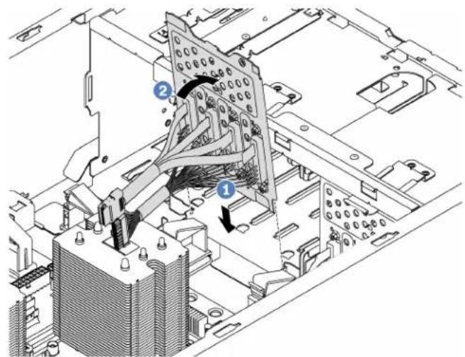
Figure 73. Simple-swap-drive backplate installation
Step 3. Connect the cables on the backplate to the system board. See "Simple-swap-drive backplate" on page 36.
After installing the simple-swap-drive backplate:
-
Reinstall all the drives and fillers (if any) in the drive cage. See "Install a simple-swap drive" on page 87.
-
Complete the parts replacement. See "Completing the parts replacement" on page 170.
Hot-swap-drive backplane replacement
Use this information to remove and install a hot-swap drive backplane.
Note: This section applies only to server models that have hot-swap-drive backplanes installed.
This section contains the following information:
- "Remove the backplane for four 2.5-inch hot-swap drives" on page 96
- "Install the backplane for four 2.5-inch hot-swap drives" on page 97
- "Remove the backplane for eight 2.5-inch hot-swap drives" on page 98
- "Install the backplane for eight 2.5-inch hot-swap drives" on page 99
- "Remove the backplane for four 3.5-inch hot-swap drives" on page 99
- "Install the backplane for four 3.5-inch hot-swap drives" on page 101
Remove the backplane for four 2.5-inch hot-swap drives
Use this information to remove the backplane for four 2.5-inch hot-swap drives.

Read the Installation Guidelines

Power Off
the server
for this task

ATTENTION: Static Sensitive Device Ground package before opening
Before removing the backplane for four 2.5-inch hot-swap drives:
- Remove the server cover. See "Remove the server cover" on page 63.
- Remove the air baffle. See "Remove the air baffle" on page 67.
- If the Fan 3 impedes your access to the backplane, remove it. See "Remove a front fan" on page 70.
- Remove all the installed drives and fillers (if any) from the drive bays. See "Remove a hot-swap drive" on page 90.
- Record the cable connections on the backplane and then disconnect all cables from the backplane. For information about the backplane cable connection, see "Hot-swap-drive backplane" on page 38.
To remove the backplane for four 2.5-inch hot-swap drives, complete the following steps:
Watch the procedure. A video of the removal process is available:
- Youtube: https://www.youtube.com/playlist?list=PLYV5R7hVcs-Acsjj4tU79GzKnWG316BYn
- Youku: http://list.youku.com/albumlist/show/id_50483452
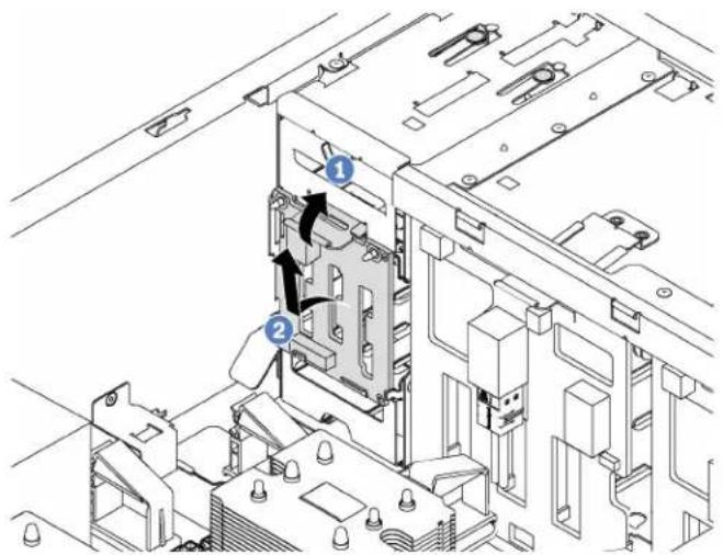
Figure 74. Removal of the backplane for four 2.5-inch hot-swap drives
Step 1. Lift the release tab to disengage the backplane.
Step 2. Remove the backplane from the chassis.
If you are instructed to return the old backplane, follow all packaging instructions and use any packaging materials that are provided.
Install the backplane for four 2.5-inch hot-swap drives
Use this information to install the backplane for four 2.5-inch hot-swap drives.

Read the Installation Guidelines

Power Off
the server
for this task

ATTENTION: Static Sensitive Device Ground package before opening
Before installing the backplane for four 2.5-inch hot-swap drives, touch the static-protective package that contains the new backplane to any unpainted surface on the outside of the server. Then, take the new backplane out of the package and place it on a static-protective surface.
To install the backplane for four 2.5-inch hot-swap drives, complete the following steps:
Watch the procedure. A video of the installation process is available:
- Youtube: https://www.youtube.com/playlist?list=PLYV5R7hVcs-Acsjj4tU79GzKnWG316BYn
- Youku: http://list.youku.com/albumlist/show/id_50483452
Step 1. Note the orientation of the new backplane.
Step 2. Lower the new backplane into the chassis and insert the new backplane into the backplane slot. Then, carefully push the new backplane inward until it is secured by the release tab and the two mounting studs on the chassis are inserted into the two holes in the backplane.
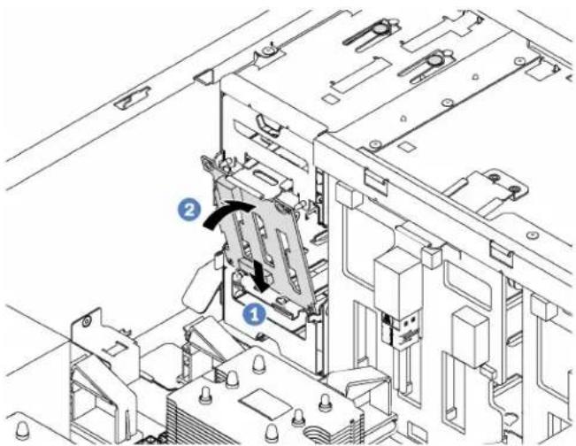
Figure 75. Installation of the backplane for four 2.5-inch hot-swap drives
Step 3. Connect the cables to the new backplane. See "Hot-swap-drive backplane" on page 38.
After installing the backplane for four 2.5-inch hot-swap drives:
- Reinstall all the drives and fillers (if any) in the drive cage. See "Install a hot-swap drive" on page 91.
- Complete the parts replacement. See "Completing the parts replacement" on page 170.
Remove the backplane for eight 2.5-inch hot-swap drives
Use this information to remove the backplane for eight 2.5-inch hot-swap drives.

Read the Installation Guidelines
Power Off
the server
for this task

ATTENTION: Static Sensitive Device Ground package before opening
Before removing the backplane for eight 2.5-inch hot-swap drives:
- Remove the server cover. See "Remove the server cover" on page 63.
- Remove the air baffle. See "Remove the air baffle" on page 67.
- Remove the front fans. See "Remove a front fan" on page 70.
- If the PCIe adapter holder impedes your access to the backplane, remove it. See "Remove the PCIe adapter holder" on page 75.
- Remove all the installed drives and fillers (if any) from the drive bays. See "Remove a hot-swap drive" on page 90.
- Record the cable connections on the backplane and then disconnect all cables from the backplane. For information about the backplane cable connection, see "Hot-swap-drive backplane" on page 38.
To remove the backplane for eight 2.5-inch hot-swap drives, complete the following steps:
Watch the procedure. A video of the removal process is available:
- Youtube: https://www.youtube.com/playlist?list=PLYV5R7hVcs-Acsjj4tU79GzKnWG316BYn
• Youku: http://list.youku.com/albumlist/show/id_50483452

Figure 76. Removal of the backplane for eight 2.5-inch hot-swap drives
Step 1. Lift the release tab to disengage the backplane.
Step 2. Rotate the top edge of the backplane away from the drive cage, and then remove the backplane.
If you are instructed to return the old backplane, follow all packaging instructions and use any packaging materials that are provided.
Install the backplane for eight 2.5-inch hot-swap drives
Use this information to install the backplane for eight 2.5-inch hot-swap drives.

Read the Installation Guidelines

Power Off
the server
for this task

ATTENTION: Static Sensitive Device Ground package before opening
Before installing the backplane for eight 2.5-inch hot-swap drives, touch the static-protective package that contains the new backplane to any unpainted surface on the outside of the server. Then, take the new backplane out of the package and place it on a static-protective surface.
To install the backplane for eight 2.5-inch hot-swap drives, complete the following steps:
Watch the procedure. A video of the installation process is available:
- Youtube: https://www.youtube.com/playlist?list=PLYV5R7hVcs-Acsjj4tU79GzKnWG316BYn
- Youku: http://list.youku.com/albumlist/show/id_50483452
Step 1. Note the orientation of the new backplane.
Step 2. Lower the new backplane into the chassis and insert the new backplane into the backplane slot. Then, carefully rotate the top edge of the new backplane toward the drive cage until it is secured by the release tab.
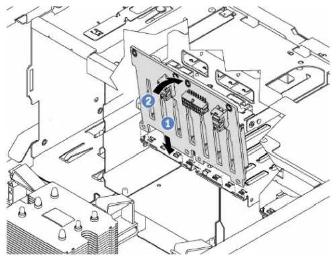
Figure 77. Installation of the backplane for eight 2.5-inch hot-swap drives
Step 3. Connect the cables to the new backplane. See "Hot-swap-drive backplane" on page 38.
After installing the backplane for eight 2.5-inch hot-swap drives:
- Reinstall all the drives and fillers (if any) in the drive cage. See "Install a hot-swap drive" on page 91.
- Complete the parts replacement. See "Completing the parts replacement" on page 170.
Remove the backplane for four 3.5-inch hot-swap drives
Use this information to remove the backplane for four 3.5-inch hot-swap drives.


ATTENTION: Static Sensitive Device Ground package before opening
Before removing the backplane for four 3.5-inch hot-swap drives:
- Remove the server cover. See "Remove the server cover" on page 63.
- Remove the air baffle. See "Remove the air baffle" on page 67.
- Remove the front fans. See "Remove a front fan" on page 70.
- If the PCIe adapter holder impedes your access to the backplane, remove it. See "Remove the PCIe adapter holder" on page 75.
- Remove all the installed drives and fillers (if any) from the drive bays. See "Remove a hot-swap drive" on page 90.
- Record the cable connections on the backplane and then disconnect all cables from the backplane. For information about the backplane cable connection, see "Hot-swap-drive backplane" on page 38.
To remove the backplane for four 3.5-inch hot-swap drives, complete the following steps:
Watch the procedure. A video of the removal process is available:
- Youtube: https://www.youtube.com/playlist?list=PLYV5R7hVcs-Acsjj4tU79GzKnWG316BYn
- Youku: http://list.youku.com/albumlist/show/id_50483452

Figure 78. Removal of the backplane for four 3.5-inch hot-swap drives
Step 1. Lift the release tab to disengage the backplane.
Step 2. Rotate the top edge of the backplane away from the drive cage, and then remove the backplane.
If you are instructed to return the old backplane, follow all packaging instructions and use any packaging materials that are provided.
Install the backplane for four 3.5-inch hot-swap drives
Use this information to install the backplane for four 3.5-inch hot-swap drives.

Read the Installation Guidelines
Power Off
the server
for this task

ATTENTION: Static Sensitive Device Ground package before opening
Before installing the backplane for four 3.5-inch hot-swap drives, touch the static-protective package that contains the new backplane to any unpainted surface on the outside of the server. Then, take the new backplane out of the package and place it on a static-protective surface.
To install the backplane for four 3.5-inch hot-swap drives, complete the following steps:
Watch the procedure. A video of the installation process is available:
- Youtube: https://www.youtube.com/playlist?list=PLYV5R7hVcs-Acsjj4tU79GzKnWG316BYn
- Youku: http://list.youku.com/albumlist/show/id_50483452
Step 1. Note the orientation of the new backplane.
Step 2. Lower the new backplane into the chassis and insert the new backplane into the backplane slot. Then, carefully rotate the top edge of the new backplane toward the drive cage until it is secured by the release tab.

Figure 79. Installation of the backplane for four 3.5-inch hot-swap drives
Step 3. Connect the cables to the new backplane. See "Hot-swap-drive backplane" on page 38.
After installing the backplane for four 3.5-inch hot-swap drives:
- Reinstall all the drives and fillers (if any) in the drive cage. See "Install a hot-swap drive" on page 91.
- Complete the parts replacement. See "Completing the parts replacement" on page 170.
Expansion drive cage replacement
Use this information to remove and install the expansion drive cage.
Note: This section applies only server models that have the expansion drive cage installed.
Remove the expansion drive cage
Use this information to remove the expansion drive cage.

Read the Installation Guidelines

Power Off the server for this task

ATTENTION: Static Sensitive Device Ground package before opening
Before removing the expansion drive cage:
- If the server is installed in a rack, extend the server from the rack.
- Remove the server cover. See "Remove the server cover" on page 63.
- If your server has the front door installed, remove the front door. See "Remove the front door" on page 57.
- Remove the front bezel. See "Remove the front bezel" on page 76.
- Remove the air baffle. See "Remove the air baffle" on page 67.
- If the Fan 3 impedes your access to the expansion drive cage, remove it. See "Remove a front fan" on page 70.
- Remove all the installed drives and fillers (if any) from the drive bays. See "Remove a hot-swap drive" on page 90
- Remove the backplane for four 2.5-inch hot-swap drives. See “Remove the backplane for four 2.5-inch hot-swap drives” on page 96.
To remove the expansion drive cage, complete the following steps:
Watch the procedure. A video of the removal process is available:
- Youtube: https://www.youtube.com/playlist?list=PLYV5R7hVcs-Acsjj4tU79GzKnWG316BYn
- Youku: http://list.youku.com/albumlist/show/id_50483452
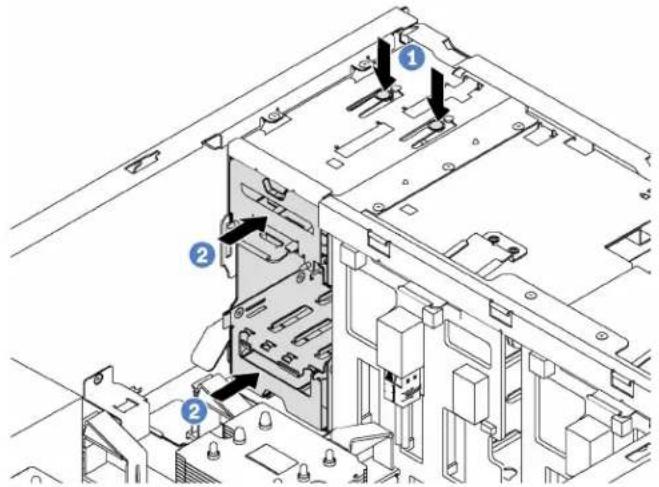
Figure 80. Expansion drive cage removal
Step 1. Press and hold the two release tabs.
Step 2. Push the expansion drive cage forward to remove it from the chassis.
After removing the expansion drive cage:
-
Depending on your needs, you can install a new expansion drive cage, a filler, an optical drive, or a tape drive to cover the bay for proper air flow.
-
If you are instructed to return the old expansion drive cage, follow all packaging instructions and use any packaging materials that are provided.
Install the expansion drive cage
Use this information to install the expansion drive cage.

Read the Installation Guidelines

Power Off
the server
for this task

ATTENTION: Static Sensitive Device Ground package before opening
Before installing the expansion drive cage:
-
If there is a filler, an optical drive, or a tape drive installed in the bay, remove it. Keep the filler in a safe place for future use. For instructions on how to remove the optical drive or tape drive, see "Remove an optical drive or a tape drive" on page 81.
-
Touch the static-protective package that contains the new expansion drive cage to any unpainted surface on the outside of the server. Then, take the new expansion drive cage out of the package and place it on a static-protective surface.
To install the expansion drive cage, complete the following step:
Watch the procedure. A video of the installation process is available:
- Youtube: https://www.youtube.com/playlist?list=PLYV5R7hVcs-Acsjj4tU79GzKnWG316BYn
- Youku: http://list.youku.com/albumlist/show/id_50483452

natural_image
Technical diagram of a server rack with two internal components and mounting hardware (no text or symbols visible)Figure 81. Expansion drive cage installation
Step 1. Slide it into the bay until it snaps into position.
After installing the expansion drive cage:
- Ensure that the signal cables are secured by the clips and are bound correctly by the Velcro strap.
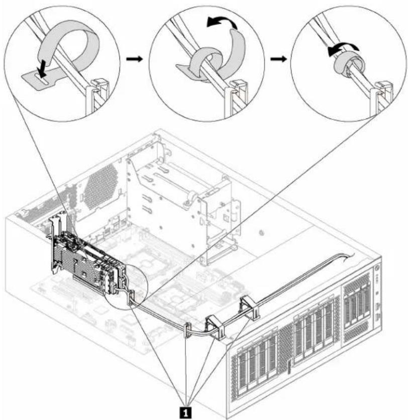
Figure 82. Securing and binding the signal cables correctly
DIMM replacement
Use this information to remove and install a DIMM.
Remove a DIMM
Use this information to remove a DIMM.

Read the Installation Guidelines
Power Off the server for this task

ATTENTION: Static Sensitive Device Ground package before opening
Attention:
- Disconnect all power cords for this task.
-
DIMMs are sensitive to static discharge and require special handling. In addition to the standard guidelines for Handling static-sensitive devices:
-
Always wear an electrostatic-discharge strap when removing or installing DIMMs. Electrostatic-discharge gloves can also be used.
- Never hold two or more DIMMs together so that they touch. Do not stack DIMMs directly on top of each other during storage.
- Never touch the gold DIMM connector contacts or allow these contacts to touch the outside of the DIMM connector housing.
- Handle DIMMs with care: never bend, twist, or drop a DIMM.
Before removing a DIMM:
- If the server is installed in a rack, extend the server from the rack.
- Remove the server cover. See "Remove the server cover" on page 63.
- Remove the air baffle. See "Remove the air baffle" on page 67.
To remove a DIMM, complete the following steps:
Watch the procedure. A video of the removal process is available:
- Youtube: https://www.youtube.com/playlist?list=PLYV5R7hVcs-Acsjj4tU79GzKnWG316BYn
- Youku: http://list.youku.com/albumlist/show/id_50483452

Figure 83. DIMM removal
Step 1. Carefully open the retaining clips on each end of the DIMM slot.
Attention: To avoid breaking the retaining clips or damaging the DIMM slots, handle the clips gently.
Step 2. Remove the DIMM.
If you are instructed to return the old DIMM, follow all packaging instructions and use any packaging materials that are provided.
DIMM installation rules
DIMMs must be installed in a specific order based on the memory configuration that you implement on your server.
Your server has 12 DIMM slots with the following features:
- Each slot supports 8 GB, 16 GB, and 32 GB DDR4 RDIMMs with Error Checking and Correcting (ECC) technology.
• Each slot supports 64 GB DDR4 LRDIMMs with ECC technology. - Your server supports up to 6 DIMMs when one processor is installed, and up to 12 DIMMs when two processors are installed.
- The minimum system memory is 8 GB (only one processor installed and only one 8 GB RDIMM installed in the CPU1 DIMM3 slot).
-
The maximum system memory is as follows:
-
384 GB using RDIMMs (two processors installed and one 32 GB RDIMM installed in each of the 12 DIMM slots)
- 768 GB using LRDIMMs (two processors installed and one 64 GB LRDIMM installed in each of the 12 DIMM slots)
For a list of supported DIMM options, see: http://www.lenovo.com/serverproven/
Before installing a DIMM, ensure that all DIMMs to be installed must be the same type. Your server supports the following types of DIMMs:
• DDR4 RDIMM with ECC technology
• DDR4 LRDIMM with ECC technology
The following illustration helps you to locate the DIMM slots on the system board.

flowchart
graph TD
    A["CPU2"] --> B["DIMM7"]
    A --> C["DIMM8"]
    A --> D["DIMM9"]
    A --> E["DIMM10"]
    A --> F["DIMM11"]
    A --> G["DIMM12"]
    H["CPU1"] --> I["DIMM1"]
    H --> J["DIMM2"]
    H --> K["DIMM3"]
    H --> L["DIMM4"]
    H --> M["DIMM5"]
    H --> N["DIMM6"]
Figure 84. DIMM slots on the system board
Your server supports the following memory modes:
• "Independent mode" on page 107
- "Mirroring mode" on page 108
• "Rank sparing mode" on page 109
Independent mode
Independent mode provides high performance memory capability. You can populate all channels with no matching requirements. Individual channels can run at different DIMM timings, but all channels must run at the same interface frequency.
Notes:
- All DIMMs to be installed must be the same type.
- When you install DIMMs with same rank and different capacity, install the DIMM that has the highest capacity first.
The following table shows the DIMM population sequence for independent mode when only one processor (CPU1) is installed.
Note: If there are three identical DIMMs to be installed for CPU1, and the three DIMMs have the same Lenovo part number, install the three DIMMs in slots 1, 2, and 3.
Table 10. Independent mode with one processor
| Total DIMMs | Processor 1 Total | ||||||
| 1 2 3 4 5 6 DIMMs | |||||||
| 1 3 1 | |||||||
| 2 3 4 | 2 | ||||||
| 3 2 3 | 4 3 | ||||||
| 4 2 3 | 4 5 4 | ||||||
| 5 1 2 | 3 4 5 5 | ||||||
| 6 1 2 | 3 4 5 6 6 | ||||||
The following table shows the DIMM population sequence for independent mode when two processors (CPU1 and CPU2) are installed.
Notes:
- If there are three identical DIMMs to be installed for CPU1, and the three DIMMs have the same Lenovo part number, install the three DIMMs in slots 1, 2, and 3.
- If there are three identical DIMMs to be installed for CPU2, and the three DIMMs have the same Lenovo part numbers, install the three DIMMs in slots 10, 11, and 12.
Table 11. Independent mode with two processors
| Total DIMMs | Processor 1 | Processor 2 | Total DIMMs | ||||||||||
| 1 | 2 | 3 | 4 | 5 | 6 | 7 | 8 | 9 | 10 | 11 | 12 | ||
| 2 | 3 | 10 | 2 | ||||||||||
| 3 | 3 | 4 | 10 | 3 | |||||||||
| 4 | 3 | 4 | 9 | 10 | 4 | ||||||||
| 5 | 2 | 3 | 4 | 9 | 10 | 5 | |||||||
| 6 | 2 | 3 | 4 | 9 | 10 | 11 | 6 | ||||||
| 7 | 2 | 3 | 4 | 5 | 9 | 10 | 11 | 7 | |||||
| 8 | 2 | 3 | 4 | 5 | 8 | 9 | 10 | 11 | 8 | ||||
| 9 | 1 | 2 | 3 | 4 | 5 | 8 | 9 | 10 | 11 | 9 | |||
| 10 | 1 | 2 | 3 | 4 | 5 | 8 | 9 | 10 | 11 | 12 | 10 | ||
| 11 | 1 | 2 | 3 | 4 | 5 | 6 | 8 | 9 | 10 | 11 | 12 | 11 | |
| 12 | 1 | 2 | 3 | 4 | 5 | 6 | 7 | 8 | 9 | 10 | 11 | 12 | 12 |
Mirroring mode
In mirroring mode, each DIMM in a pair must be identical in size and architecture. The channels are grouped in pairs with each channel receiving the same data. One channel is used as a backup of the other, which provides redundancy.
Note: All memory modules to be installed must be the same type with the same capacity, frequency, voltage, and number of ranks.
The following table shows the DIMM population sequence for mirroring mode when only one processor (CPU1) is installed.
Table 12. Mirroring mode with one processor
| Total DIMMs | Processor 1 Total | ||||||
| 1 2 3 4 5 6 DIMMs | |||||||
| 2 2 3 | 2 | ||||||
| 3 1 2 | 3 3 | ||||||
| 4 2 3 | 4 5 4 | ||||||
| 6 1 2 | 3 4 5 6 6 | ||||||
The following table shows the DIMM population sequence for mirroring mode when two processors (CPU1 and CPU2) are installed.
Table 13. Mirroring mode with two processors
| Total DIMMs | Processor 1 Processor 2 Total | DIMMs | |||||||||||
| 1 | 2 | 3 | 4 | 5 | 6 | 7 | 8 | 9 | 10 | 11 | 12 | ||
| 4 | 2 | 3 | 10 | 11 | 4 | ||||||||
| 5 | 1 | 2 | 3 | 10 | 11 | 5 | |||||||
| 6 | 1 | 2 | 3 | 10 | 11 | 12 | 6 | ||||||
| 8 | 2 | 3 | 4 | 5 | 8 | 9 | 10 | 11 | 8 | ||||
| 9 | 1 | 2 | 3 | 4 | 5 | 6 | 10 | 11 | 12 | 9 | |||
| 10 | 1 | 2 | 3 | 4 | 5 | 6 | 8 | 9 | 10 | 11 | 10 | ||
| 12 | 1 | 2 | 3 | 4 | 5 | 6 | 7 | 8 | 9 | 10 | 11 | 12 | 12 |
Rank sparing mode
In rank sparing mode, one rank of a DIMM works as the spare rank for the other ranks on the same channel. The spare rank is not available as system memory.
Notes:
- All DIMMs to be installed must be the same type with the same capacity, frequency, voltage, and ranks.
- If the rank of installed DIMMs is one rank, rank sparing mode is not supported. If the rank of installed DIMMs is more than one rank, follow the installation rules listed in the following tables.
The following table shows the DIMM population sequence for rank sparing mode when only one processor (CPU1) is installed.
Table 14. Rank sparing mode with one processor
| Total DIMMs | Processor 1 Total | ||||||
| 1 2 3 4 | 5 6 DIMMs | ||||||
| 1 | 3 1 | ||||||
| 2 | 3 4 | 2 | |||||
| 3 2 3 | 4 | 3 | |||||
| 4 2 3 | 4 5 4 | ||||||
| 5 1 2 | 3 4 5 5 | ||||||
| 6 1 2 | 3 4 5 6 6 | ||||||
The following table shows the DIMM population sequence for rank sparing mode when two processors (CPU1 and CPU2) are installed.
Table 15. Rank sparing mode with two processors
| Total DIMMs | Processor 1 Processor 2 Total | ||||||||||||
| 1 2 3 4 | 5 6 7 8 9 | 10 11 12 | DIMMs | ||||||||||
| 2 | 3 | 10 | 2 | ||||||||||
| 3 | 3 4 | 10 | 3 | ||||||||||
| 4 | 3 4 | 9 10 | 4 | ||||||||||
| 5 | 2 3 4 | 9 10 | 5 | ||||||||||
| 6 | 2 | 3 | 4 | 9 | 10 | 11 | 6 | ||||||
| 7 | 2 | 3 | 4 | 5 | 9 | 10 | 11 | 7 | |||||
| 8 | 2 | 3 | 4 | 5 | 8 | 9 | 10 | 11 | 8 | ||||
| 9 1 2 | 3 4 5 | 8 9 | 10 11 | 9 | |||||||||
| 10 | 1 | 2 | 3 | 4 | 5 | 8 | 9 | 10 | 11 | 12 | 10 | ||
| 11 | 1 | 2 | 3 | 4 | 5 | 6 | 8 | 9 | 10 | 11 | 12 | 11 | |
| 12 | 1 2 3 | 4 5 6 7 | 8 9 10 11 | 12 | 12 | ||||||||
Install a DIMM
Use this information to install a DIMM.

Read the Installation Guidelines
Power Off
the server
for this task

ATTENTION: Static Sensitive Device Ground package before opening
Attention:
- Disconnect all power cords for this task.
-
DIMMs are sensitive to static discharge and require special handling. In addition to the standard guidelines for Handling static-sensitive devices:
-
Always wear an electrostatic-discharge strap when removing or installing DIMMs. Electrostatic-discharge gloves can also be used.
- Never hold two or more DIMMs together so that they touch. Do not stack DIMMs directly on top of each other during storage.
- Never touch the gold DIMM connector contacts or allow these contacts to touch the outside of the DIMM connector housing.
- Handle DIMMs with care: never bend, twist, or drop a DIMM.
Before installing a DIMM:
- Touch the static-protective package that contains the new DIMM to any unpainted surface on the outside of the server. Then, take the new DIMM out of the package and place it on a static-protective surface.
- Ensure that you consider and follow the DIMM installation rules when performing the operation. See "DIMM installation rules" on page 106.
To install a DIMM, complete the following steps:
Watch the procedure. A video of the installation process is available:
- Youtube: https://www.youtube.com/playlist?list=PLYV5R7hVcs-Acsjj4tU79GzKnWG316BYn
- Youku: http://list.youku.com/albumlist/show/id_50483452

Figure 85. DIMM installation
Step 1. Open the retaining clips on each end of the DIMM slot. Then, install the DIMM into the slot.
Attention: To avoid breaking the retaining clips or damaging the DIMM slots, open and close the clips gently.
Step 2. Firmly press the DIMM straight down into the slot by applying pressure on both ends of the DIMM simultaneously. The retaining clips snap into the locked position when the DIMM is firmly seated in the slot.
Note: If there is a gap between the DIMM and the retaining clips, the DIMM has not been correctly inserted; open the retaining clips, remove the DIMM, and then reinsert it.
After installing a DIMM, complete the parts replacement. See “Completing the parts replacement” on page 170.
PCIe adapter retainer replacement
Use this information to remove and install the PCIe adapter retainer, which helps to secure PCIe adapters.
Remove the PCIe adapter retainer
Use this information to remove the PCIe adapter retainer.
Before removing the PCIe adapter retainer:
- If the server is installed in a rack, extend the server from the rack.
- Remove the server cover. See "Remove the server cover" on page 63.
To remove the PCIe adapter retainer, complete the following step:
Watch the procedure. A video of the removal process is available:
- Youtube: https://www.youtube.com/playlist?list=PLYV5R7hVcs-Acsjj4tU79GzKnWG316BYn
- Youku: http://list.youku.com/albumlist/show/id_50483452

natural_image
Technical line drawing of an internal mechanical assembly with no visible text or symbolsFigure 86. PCIe adapter retainer removal
Step 1. Grab the touch point to lift the retainer from the chassis.
Install the PCIe adapter retainer
Use this information to install the PCIe adapter retainer.

Read the Installation Guidelines

Power Off
the server
for this task
To install the PCIe adapter retainer, complete the following steps:
Watch the procedure. A video of the installation process is available:
- Youtube: https://www.youtube.com/playlist?list=PLYV5R7hVcs-Acsjj4tU79GzKnWG316BYn
- Youku: http://list.youku.com/albumlist/show/id_50483452

Figure 87. PCIe adapter retainer installation
Step 1. Position the new PCIe adapter retainer over PCIe slots. Then, align the tabs on the retainer with the corresponding notches on the chassis and insert the tabs into the notches.
Step 2. Pivot the PCIe adapter retainer downward until the notches on the PCIe adapter retainer catch on the mounting studs on the chassis.
After installing the PCIe adapter retainer, complete the parts replacement. See “Completing the parts replacement” on page 170.
PCIe adapter replacement
Use this information to remove and install a PCIe adapter.
Your server comes with six PCIe slots. Depending on your needs, you can install a PCIe adapter to obtain the corresponding function or remove the adapter if necessary. The PCIe adapter can be an Ethernet adapter, a host bus adapter, a RAID adapter, a graphics adapter, or any other supported PCIe adapters. PCIe adapters vary by type, but the installation and removal procedures are the same.
Note: For a list of the supported PCIe adapters, see: http://www.lenovo.com/serverproven/
Remove a PCIe adapter
Use this information to remove a PCIe adapter.

Read the Installation Guidelines
Power Off
the server
for this task

ATTENTION: Static Sensitive Device Ground package before opening
Before removing a PCIe adapter:
- If the server is installed in a rack, extend the server from the rack.
- Remove the server cover. See "Remove the server cover" on page 63.
- Remove the air baffle. See "Remove the air baffle" on page 67.
-
Remove the PCIe adapter retainer. See "Remove the PCIe adapter retainer" on page 111.
-
Record the cable connections on the PCIe adapter and then disconnect all cables from the PCIe adapter.
Notes:
- Depending on the specific type, your PCIe adapter might look different from the illustration in this topic.
- Use any documentation that comes with the PCIe adapter and follow those instructions in addition to the instructions in this topic.
To remove a PCIe adapter, complete the following steps:
Watch the procedure. A video of the removal process is available:
- Youtube: https://www.youtube.com/playlist?list=PLYV5R7hVcs-Acsjj4tU79GzKnWG316BYn
- Youku: http://list.youku.com/albumlist/show/id_50483452
Step 1. Grasp the PCIe adapter by its edges and carefully pull it out of the PCIe slot.

natural_image
Technical diagram of a computer motherboard showing CPU socket, drive bays, and hardware connections (no text or labels)Figure 88. PCIe adapter removal
Note: The PCIe adapter might fit tightly into the PCIe slot. If necessary, alternatively move each side of the PCIe adapter a small and equal amount until it is removed from the slot.
After removing the PCIe adapter:
- Install a new PCIe adapter to replace the old one. See "Install a PCIe adapter" on page 114. Otherwise, install the bracket for the PCIe slot to cover the place.
- If you are instructed to return the old PCIe adapter, follow all packaging instructions and use any packaging materials that are provided.
Install a PCIe adapter
Use this information to install a PCIe adapter.

Read the Installation Guidelines
Power Off
the server
for this task

ATTENTION: Static Sensitive Device
ground package before opening
Observe the following guidelines when select a PCIe slot:
- For server models that support NVMe drives, the NVMe adapter can be installed only in PCIe slot 2.
- For RAID adapters or host bus adapters, you can install them in either PCIe slot 1 or PCIe slot 2.
- For server models with one processor, you can install a double-width graphics adapter only in PCIe slot 3. For server models with two processors, you can install up to two double-width graphics adapters in PCIe slot 3 and PCIe slot 5. After any double-width graphics adapter is installed, PCIe slot 4 or PCIe slot 6 becomes unavailable because the space is occupied by the double-width adapter.
Notes:
• Depending on the specific type, your PCIe adapter might look different from the illustration in this topic.
- Use any documentation that comes with the PCIe adapter and follow those instructions in addition to the instructions in this topic.
Before installing a PCIe adapter:
-
If a bracket is installed in the PCIe slot, remove it. Store the bracket for the PCIe slot in case that you later remove the PCIe adapter and need the bracket to cover the place.
-
Touch the static-protective package that contains the new PCIe adapter to any unpainted surface on the outside of the server. Then, take the new PCIe adapter out of the package and place it on a static-protective surface.
To install a PCIe adapter, complete the following steps:
Watch the procedure. A video of the installation process is available:
- Youtube: https://www.youtube.com/playlist?list=PLYV5R7hVcs-Acsjj4tU79GzKnWG316BYn
- Youku: http://list.youku.com/albumlist/show/id_50483452
Step 1. Locate the appropriate PCIe slot. For information about the PCIe slot, see "Specifications" on page 3.
Step 2. Position the new PCIe adapter over the PCIe slot. Then, carefully press the PCIe adapter straight down until it is securely seated in the slot.

natural_image
Technical diagram of a computer motherboard showing CPU socket, drive bays, and internal components (no text or labels)Figure 89. PCIe adapter installation
Step 3. Depending on the type of the PCIe adapter, you might need to connect any required cables. Refer to "Internal cable routing" on page 27 or the documentation that comes with the PCIe adapter for specific information.
After installing the PCIe adapter:
- Install the PCIe adapter retainer to help secure the PCIe adapter. See "Install the PCIe adapter retainer" on page 112.
CMOS battery replacement
Use this information to remove and install the CMOS battery.
Remove the CMOS battery
Use this information to remove the CMOS battery.

Read the Installation Guidelines

Power Off the server for this task

ATTENTION: Static Sensitive Device Ground package before opening
The following tips describe information that you must consider when removing the CMOS battery.
- Lenovo has designed this product with your safety in mind. The lithium CMOS battery must be handled correctly to avoid possible danger. If you replace the CMOS battery, you must adhere to the following instructions.
Note: In the U.S., call 1-800-IBM-4333 for information about battery disposal.
- If you replace the original lithium battery with a heavy-metal battery or a battery with heavy-metal components, be aware of the following environmental consideration. Batteries and accumulators that contain heavy metals must not be disposed of with normal domestic waste. They will be taken back free of charge by the manufacturer, distributor, or representative, to be recycled or disposed of in a proper manner.
- To order replacement batteries, call 1-800-IBM-SERV within the U.S., and 1-800-465-7999 or 1-800-465-6666 within Canada. Outside the U.S. and Canada, call your support center or business partner.
Note: After you replace the CMOS battery, you must reconfigure the server and reset the system date and time.
S004

CAUTION:
When replacing the lithium battery, use only Lenovo specified part number or an equivalent type battery recommended by the manufacturer. If your system has a module containing a lithium battery, replace it only with the same module type made by the same manufacturer. The battery contains lithium and can explode if not properly used, handled, or disposed of. Do not:
- Throw or immerse into water
• Heat to more than 100°C (212°F)
• Repair or disassemble
Dispose of the battery as required by local ordinances or regulations.
S002

CAUTION:
Make sure all power cords are disconnected from system when reading in this manual and the following step is required to complete: Disconnect the power cords and all external cables from the rear of the enclosure.
Before removing the CMOS battery:
- If the server is installed in a rack, extend the server from the rack.
- Remove the server cover. See "Remove the server cover" on page 63.
- Remove any parts and disconnect any cables that might impede your access to the CMOS battery.
To remove the CMOS battery, complete the following steps:
Watch the procedure. A video of the removal process is available:
- Youtube: https://www.youtube.com/playlist?list=PLYV5R7hVcs-Acsjj4tU79GzKnWG316BYn
- Youku: http://list.youku.com/albumlist/show/id_50483452
Step 1. Locate the CMOS battery. See "System board components" on page 24.
Step 2. Remove the CMOS battery.
Attention:
- Failing to remove the CMOS battery properly might damage the socket on the system board. Any damage to the socket might require replacing the system board.
- Do not tilt or push the CMOS battery by using excessive force.

natural_image
Diagram of a circular mechanical component with an arrow indicating direction (no text or symbols)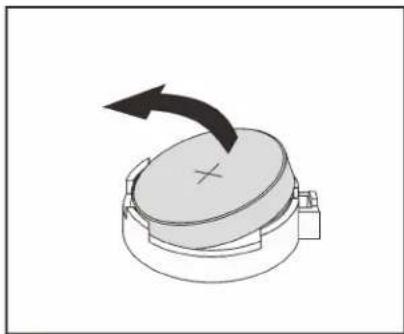
natural_image
Diagram of a mechanical component with a rotating arrow indicating rotation (no text or symbols)Figure 90. CMOS battery removal
After removing the CMOS battery:
- Install a new CMOS battery. See "Install the CMOS battery" on page 117.
- Dispose of the CMOS battery as required by local ordinances or regulations.
Install the CMOS battery
Use this information to install the CMOS battery.

Read the Installation Guidelines

Power Off
the server
for this task

ATTENTION: Static Sensitive Device Ground package before opening
The following tips describe information that you must consider when installing the CMOS battery.
- Lenovo has designed this product with your safety in mind. The lithium battery must be handled correctly to avoid possible danger. If you install the CMOS battery, you must adhere to the following instructions.
Note: In the U. S., call 1-800-IBM-4333 for information about battery disposal.
- If you replace the original lithium battery with a heavy-metal battery or a battery with heavy-metal components, be aware of the following environmental consideration. Batteries and accumulators that contain heavy metals must not be disposed of with normal domestic waste. They will be taken back free of charge by the manufacturer, distributor, or representative, to be recycled or disposed of in a proper manner.
- To order replacement batteries, call 1-800-IBM-SERV within the U.S., and 1-800-465-7999 or 1-800-465-6666 within Canada. Outside the U.S. and Canada, call your support center or business partner.
Note: After you install the CMOS battery, you must reconfigure the server and reset the system date and time.
S004

CAUTION:
When replacing the lithium battery, use only Lenovo specified part number or an equivalent type battery recommended by the manufacturer. If your system has a module containing a lithium battery, replace it only with the same module type made by the same manufacturer. The battery contains lithium and can explode if not properly used, handled, or disposed of. Do not:
- Throw or immerse into water
• Heat to more than 100°C (212°F)
• Repair or disassemble
Dispose of the battery as required by local ordinances or regulations.
S002

CAUTION:
Make sure all power cords are disconnected from system when reading in this manual and the following step is required to complete: Disconnect the power cords and all external cables from the rear of the enclosure.
To install the CMOS battery, complete the following steps:
Watch the procedure. A video of the installation process is available:
- Youtube: https://www.youtube.com/playlist?list=PLYV5R7hVcs-Acsjj4tU79GzKnWG316BYn
- Youku: http://list.youku.com/albumlist/show/id_50483452
Step 1. Touch the static-protective package that contains the new CMOS battery to any unpainted surface on the outside of the server. Then, take the new CMOS battery out of the package and place it on a static-protective surface.
Step 2. Install the new CMOS battery as shown. Ensure that the CMOS battery retainer holds the battery securely.
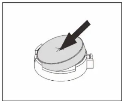
natural_image
Diagram of a mechanical component with a black arrow pointing to a circular feature (no text or symbols)
natural_image
Diagram of a circular mechanical component with a downward arrow and cross mark (no text or symbols)Figure 91. CMOS battery installation
After installing the CMOS battery, do the following:
- Complete the parts replacement. See "Complete the parts replacement" on page 170.
- Start the Setup utility program to reset the date, time, and any passwords.
Serial port module replacement
Use this information to remove and install the serial port module.
Note: Depending on the model, your server might come with a serial port module.
Remove the serial port module
Use this information to remove the serial port module.

Read the Installation Guidelines
Power Off
the server
for this task

ATTENTION: Static Sensitive Device
ground package before opening
Before removing the serial port module:
- If the server is installed in a rack, extend the server from the rack.
- Remove the server cover. See "Remove the server cover" on page 63.
- Remove the air baffle. See "Remove the air baffle" on page 67.
- Remove the PCIe adapter retainer. See "Remove the PCIe adapter retainer" on page 111.
To remove the serial port module, complete the following steps:
Watch the procedure. A video of the removal process is available:
- Youtube: https://www.youtube.com/playlist?list=PLYV5R7hVcs-Acsjj4tU79GzKnWG316BYn
- Youku: http://list.youku.com/albumlist/show/id_50483452
Step 1. Disconnect the cable of the serial port module from the system board.
Step 2. Lift the serial port module out of the chassis.

natural_image
Technical diagram of a server rack with heat exchanger and drive mechanism (no text or labels)Figure 92. Serial port module removal
After removing the serial port module:
- Install a new serial port module or a slot bracket to cover the place.
- If you are instructed to return the old serial port module, follow all of the packaging instructions and use any packaging materials that are provided.
Install the serial port module
Use this information to install the serial port module.

Read the Installation Guidelines
Power Off
the server
for this task

ATTENTION: Static Sensitive Device
ground package before opening
Before installing the serial port module:
- If the slot is covered with a slot bracket, remove the slot bracket from the chassis. Store the bracket in case that you later remove the serial port module and need the bracket to cover the place.
- Touch the static-protective package that contains the new serial port module to any unpainted surface on the outside of the server. Then, take the new serial port module out of the package and place it on a static-protective surface.
To install the serial port module, complete the following steps:
Watch the procedure. A video of the installation process is available:
- Youtube: https://www.youtube.com/playlist?list=PLYV5R7hVcs-Acsjj4tU79GzKnWG316BYn
- Youku: http://list.youku.com/albumlist/show/id_50483452
Step 1. Insert the serial port module into the dedicated slot.
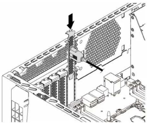
natural_image
Technical diagram of an internal server rack with a mechanical component inserted, showing no text or symbols.Figure 93. Serial port module installation
Step 2. Connect the cable of the serial port module to the serial-port-module connector on the system board. For the location of the serial-port-module connector, see "System board components" on page 24.
After installing the serial port module, complete the parts replacement. See "Complete the parts replacement" on page 170.
M.2 backplane and M.2 drive replacement
Use this information to remove and install the M.2 backplane and M.2 drive (also known as M.2 module).
Remove the M.2 backplane and M.2 drive
Use this information to remove the M.2 backplane and M.2 drive.

Read the Installation Guidelines
Power Off
the server
for this task

ATTENTION: Static Sensitive Device
ground package before opening
Before removing the M.2 backplane and M.2 drive:
- If the server is installed in a rack, extend the server from the rack.
- Remove the server cover. See "Remove the server cover" on page 63.
- For easier operation, remove the PCIe adapter retainer. See "Remove the PCIe adapter retainer" on page 111.
- Remove any parts and disconnect any cables that might impede your access to the M.2 backplane and M.2 drive.
To remove the M.2 backplane and M.2 drive, complete the following steps:
Watch the procedure. A video of the removal process is available:
- Youtube: https://www.youtube.com/playlist?list=PLYV5R7hVcs-Acsjj4tU79GzKnWG316BYn
- Youku: http://list.youku.com/albumlist/show/id_50483452
- Youtube: https://www.youtube.com/playlist?list=PLYV5R7hVcs-Acsjj4tU79GzKnWG316BYn - Youku: http://list.youku.com/albumlist/show/id_50483452
Step 1. Grasp the M.2 backplane at both ends and pull it straight up to remove it from the system board.

natural_image
Isometric technical diagram of a computer motherboard with labeled components and directional arrows (no text or symbols present)Figure 94. M.2 backplane removal
Step 2. Remove the M.2 drive from the M.2 backplane by doing the following:

Figure 95. M.2 drive removal
a. Press both sides of the retainer
b. Slide the retainer backward to loosen the M.2 drive from the M.2 backplane.
Note: If the M.2 backplane has two M.2 drives, they will both release outward when you slide the retainer backward.
c. Rotate the M.2 drive away from the M.2 backplane.
d. Pull it away from the connector 2 at an angle of approximately 30 degrees.
If you are instructed to return the old M.2 backplane or M.2 drive, follow all of the packaging instructions and use any packaging materials that are provided.
Adjust the retainer on the M.2 backplane
Use this information to adjust the retainer on the M.2 backplane.

Read the Installation Guidelines

Power Off
the server
for this task

ATTENTION: Static Sensitive Device Ground package before opening
Before adjusting the retainer on the M.2 backplane, locate the correct keyhole that the retainer should be installed into to accommodate the particular size of the M.2 drive you wish to install.
To adjust the retainer on the M.2 backplane, complete the following steps:
Watch the procedure. A video of the adjustment process is available:
- Youtube: https://www.youtube.com/playlist?list=PLYV5R7hVcs-Acsjj4tU79GzKnWG316BYn
- Youku: http://list.youku.com/albumlist/show/id_50483452
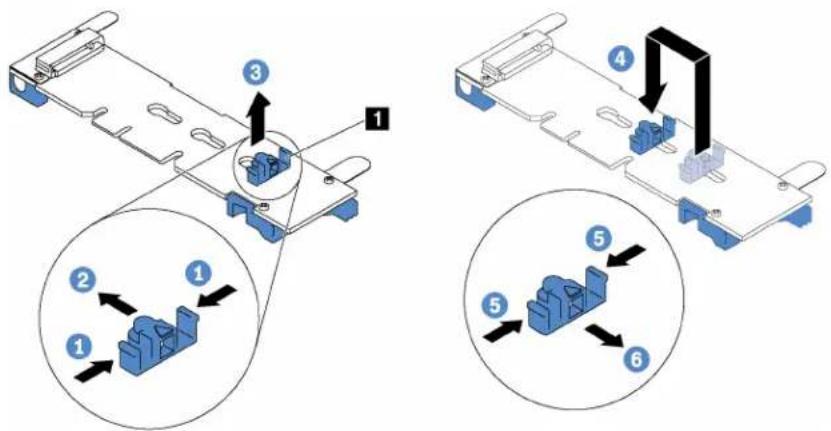
Figure 96. M.2 retainer adjustment
Step 1. Press both sides of the retainer
Step 2. Move the retainer forward until it is in the large opening of the keyhole.
Step 3. Take the retainer out of the keyhole.
Step 4. Insert the retainer into the correct keyhole.
Step 5. Press both sides of the retainer.
Step 6. Slide the retainer backwards until it is seated in place.
Install the M.2 backplane and M.2 drive
Use this information to install the M.2 backplane and M.2 drive.

Read the Installation Guidelines

Power Off
the server
for this task

ATTENTION: Static Sensitive Device
ground package before opening
Before installing the M.2 backplane and M.2 drive:
-
Touch the static-protective package that contains the new M.2 backplane and M.2 drive to any unpainted surface on the outside of the server. Then, take the new M.2 backplane and M.2 drive out of the package and place them on a static-protective surface.
-
Adjust the retainer on the M.2 backplane to accommodate the particular size of the M.2 drive you wish to install. See "Adjust the retainer on the M.2 backplane" on page 122.
-
Locate the connector on each side of the M.2 backplane.
Notes:
- Some M.2 backplanes support two identical M.2 drives. When two M.2 drives are installed, align and support both M.2 drives when sliding the retainer forward to secure the M.2 drives.
• Install the M.2 drive in slot 0 first.
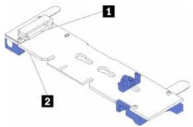
1 Slot 0
2 Slot 1
Figure 97. M.2 drive slot
To install the M.2 backplane and M.2 drive, complete the following steps:
Watch the procedure. A video of the installation process is available:
- Youtube: https://www.youtube.com/playlist?list=PLYV5R7hVcs-Acsjj4tU79GzKnWG316BYn
- Youku: http://list.youku.com/albumlist/show/id_50483452
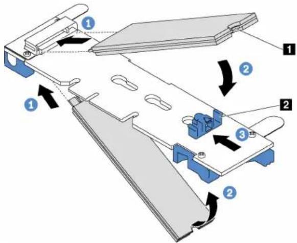
Figure 98. M.2 drive installation
Step 1. Insert the M.2 drive at an angle of approximately 30 degrees into the connector.
Note: If your M.2 backplane supports two M.2 drives, insert the M.2 drives into the connectors at both sides.
Step 2. Rotate the M.2 drive down until the notch 1 catches on the lip of the retainer 2.
Step 3. Slide the retainer forward (toward the connector) to secure the M.2 drive into place.
Attention: When sliding the retainer forward, ensure that the two nubs 3 on the retainer enter the small holes 4 on the M.2 backplane. Once they enter the holes, you will hear a soft "click" sound.

Figure 99. Instruction for sliding the retainer
Step 4. Align the blue plastic supports at each end of the M.2 backplane with the guide pins on the system board. Then, insert the M.2 backplane into the M.2 slot on the system board and press it down to fully seat it.

natural_image
Isometric technical diagram of a computer motherboard with cooling fans and heat sinks (no text or labels)Figure 100. M.2 backplane installation
After installing the M.2 backplane and M.2 drive:
- Install the PCIe adapter retainer. See "Install the PCIe adapter retainer" on page 112.
- Complete the parts replacement. See "Complete the parts replacement" on page 170.
TCM replacement (for China only)
Use this information to remove and install the TCM.
Remove the TCM (for China only)
Use this information to remove the TCM.

Read the Installation Guidelines

Power Off the server for this task

ATTENTION: Static Sensitive Device Ground package before opening
Before removing the TCM:
- If the server is installed in a rack, extend the server from the rack.
- Remove the server cover. See "Remove the server cover" on page 63.
- Remove the PCIe adapter retainer. See "Remove the PCIe adapter retainer" on page 111.
To remove the TCM, complete the following step:
Watch the procedure. A video of the removal process is available:
- Youtube: https://www.youtube.com/playlist?list=PLYV5R7hVcs-Acsjj4tU79GzKnWG316BYn
- Youku: http://list.youku.com/albumlist/show/id_50483452

natural_image
Top-down schematic of a computer motherboard showing CPU socket, RAM slots, and connectors (no text or labels)Figure 101. TCM removal
Step 1. Press and hold the release latch, and then lift the TCM straight up.
Note: Carefully handle the TCM by its edges.
If you are instructed to return the old TCM, follow all packaging instructions and use any packaging materials that are provided.
Install the TCM (for China only)
Use this information to install the TCM.

Read the Installation Guidelines

Power Off
the server
for this task

ATTENTION: Static Sensitive Device Ground package before opening
Before installing the TCM, touch the static-protective package that contains the new TCM to any unpainted surface on the outside of the server. Then, take the new TCM out of the package and place it on a static-protective surface.
To install the TCM, complete the following step:
Watch the procedure. A video of the installation process is available:
- Youtube: https://www.youtube.com/playlist?list=PLYV5R7hVcs-Acsjj4tU79GzKnWG316BYn
- Youku: http://list.youku.com/albumlist/show/id 50483452
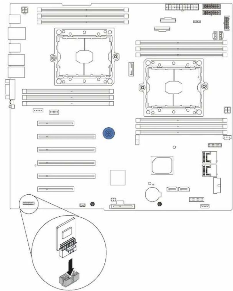
natural_image
Top-down schematic of a computer motherboard showing CPU socket, RAM slots, and connectors (no text or labels)Figure 102. TCM installation
Step 1. Locate the TCM connector on the system board and then insert the TCM into the TCM connector on the system board.
Note: Carefully handle the TCM by its edges.
After installing the TCM:
- Install the PCIe adapter retainer. See "Install the PCIe adapter retainer" on page 112.
- Complete the parts replacement. See d "Complete the parts replacement" on page 170.
Intrusion switch replacement
Use this information to remove and install the intrusion switch. The intrusion switch informs you that the server cover is not properly installed or closed by creating an event in the system event log (SEL).
Remove the intrusion switch
Use this information to remove the intrusion switch.

Read the Installation Guidelines
Power Off
the server
for this task

ATTENTION: Static Sensitive Device Ground package before opening
Before removing the intrusion switch:
- If the server is installed in a rack, extend the server from the rack.
- Remove the server cover. See "Remove the server cover" on page 63.
- Remove the PCIe adapter retainer. See "Remove the PCIe adapter retainer" on page 111.
To remove the intrusion switch, complete the following steps:
Watch the procedure. A video of the removal process is available:
- Youtube: https://www.youtube.com/playlist?list=PLYV5R7hVcs-Acsjj4tU79GzKnWG316BYn
- Youku: http://list.youku.com/albumlist/show/id_50483452
Step 1. Disconnect the cable of the intrusion switch from the system board.
Step 2. Slide the intrusion switch as shown to remove it from the chassis.

natural_image
Technical diagram of a mechanical assembly with a component being inserted, showing no text or symbols.Figure 103. Intrusion switch removal
If you are instructed to return the old intrusion switch, follow all of the packaging instructions and use any packaging materials that are provided.
Install the intrusion switch
Use this information to install the intrusion switch.


ATTENTION: Static Sensitive Device Ground package before opening
Before installing the intrusion switch, touch the static-protective package that contains the new intrusion switch to any unpainted surface on the outside of the server. Then, take the new intrusion switch out of the package and place them on a static-protective surface.
To install the intrusion switch, complete the following steps:
Watch the procedure. A video of the installation process is available:
- Youtube: https://www.youtube.com/playlist?list=PLYV5R7hVcs-Acsjj4tU79GzKnWG316BYn
- Youku: http://list.youku.com/albumlist/show/id_50483452
Step 1. Insert the intrusion switch into the chassis and push it in the direction as shown until it is fully seated.

natural_image
Technical diagram of a mechanical assembly with rollers and a component, showing no text or symbolsFigure 104. Intrusion switch installation
Step 2. Connect the cable of the intrusion switch to the intrusion switch connector on the system board. For the location of the intrusion switch connector, refer to "System board components" on page 24.
After installing the intrusion switch:
- Install the PCIe adapter retainer. See "Install the PCIe adapter retainer" on page 112.
- Complete the parts replacement. See "Complete the parts replacement" on page 170.
Fixed power supply replacement
Use this information to remove and install the fixed power supply.
Note: This section applies only to server models that have a fixed power supply installed.
Remove the fixed power supply
Use this information to remove the fixed power supply.

Read the Installation Guidelines

Power Off
the server
for this task

ATTENTION: Static Sensitive Device Ground package before opening
S035

CAUTION:
Never remove the cover on a power supply or any part that has this label attached.
Hazardous voltage, current, and energy levels are present inside any component that has this label attached. There are no serviceable parts inside these components. If you suspect a problem with one of these parts, contact a service technician.
S002
CAUTION:
Make sure all power cords are disconnected from system when reading in this manual and the following step is required to complete: Disconnect the power cords and all external cables from the rear of the enclosure.
S001

Electrical current from power, telephone, and communication cables is hazardous.
To avoid a shock hazard:
- Do not connect or disconnect any cables or perform installation, maintenance, or reconfiguration of this product during an electrical storm.
- Connect all power cords to a properly wired and grounded electrical outlet.
- Connect to properly wired outlets any equipment that will be attached to this product.
- When possible, use one hand only to connect or disconnect signal cables.
- Never turn on any equipment when there is evidence of fire, water, or structural damage.
- Disconnect the attached power cords, telecommunications systems, networks, and modems before you open the device covers, unless instructed otherwise in the installation and configuration procedures.
- Connect and disconnect cables as described in the following table when installing, moving, or opening covers on this product or attached devices.
To Connect: To Disconnect:
- Turn everything OFF.
- First, attach all cables to devices.
- Attach signal cables to connectors.
- Attach power cords to outlet.
-
Turn device ON.
-
Turn everything OFF.
- First, remove power cords from outlet.
- Remove signal cables from connectors.
- Remove all cables from devices.

XXXW \~ AC
额定电压 XXX-XXXV
額定電壓 /XXX-XXXV
额定电流
額定電流 A.A/A.AA
额定频率 XX/XXHz
額定頻率
Figure 105. Fixed power supply label on the cover
The following tips describe the information that you must consider when you remove a power supply with dc input.
CAUTION:
240 V dc input (input range: 180-300 V dc) is supported in China ONLY. Power supply with 240 V dc input cannot support hot plugging power cord function. Before removing the power supply with dc input, please turn off server or disconnect dc power sources at the breaker panel or by turning off the power source. Then, remove the power cord.
Never remove the cover on a power supply or any part that has this label attached.
Hazardous voltage, current, and energy levels are present inside any component that has this label attached. There are no serviceable parts inside these components. If you suspect a problem with one of these parts, contact a service technician.
S019

CAUTION:
The power-control button on the device does not turn off the electrical current supplied to the device. The device also might have more than one connection to dc power. To remove all electrical current from the device, ensure that all connections to dc power are disconnected at the dc power input terminals.
S029


DANGER
Electrical current from power, telephone, and communication cables is hazardous.
To avoid a shock hazard:
- Do not connect or disconnect any cables or perform installation, maintenance, or reconfiguration of this product during an electrical storm.
- Connect all power cords to a properly wired and grounded power source.
- Connect to properly wired power sources any equipment that will be attached to this product.
- When possible, use one hand only to connect or disconnect signal cables.
- Never turn on any equipment when there is evidence of fire, water, or structural damage.
- Disconnect the attached ac power cords, dc power sources, network connections, telecommunications systems, and serial cables before you open the device covers, unless you are instructed otherwise in the installation and configuration procedures.
- Connect and disconnect cables as described in the following table when you install, move, or open covers on this product or attached devices.
To Connect: To Disconnect:
- Turn OFF all power sources and equipment that is to be attached to this product.
- Attach signal cables to the product.
-
Attach power cords to the product.
-
For ac systems, use appliance inlets.
-
For dc systems, ensure correct polarity of -48 V dc connections: RTN is + and -48 V dc is -. Earth ground should use a two-hole lug for safety.
-
Attach signal cables to other devices.
-
Connect power cords to their sources.
-
Turn ON all the power sources.
-
Turn OFF all power sources and equipment that is to be attached to this product.
- For ac systems, remove all power cords from the chassis power receptacles or interrupt power at the ac power distribution unit.
- For dc systems, disconnect dc power sources at the breaker panel or by turning off the power source. Then, remove the dc cables.
-
Remove the signal cables from the connectors.
-
Remove all cables from the devices.
Before removing the fixed power supply:
- If the server is installed in a rack, extend the server from the rack.
- Disconnect the power cord from the fixed power supply.
- Remove the server cover. See "Remove the server cover" on page 63.
- Remove the air baffle. See "Remove the air baffle" on page 67.
- Remove all cables on the fixed power supply from the system board.
To remove the fixed power supply, complete the following steps:
Watch the procedure. A video of the removal process is available:
- Youtube: https://www.youtube.com/playlist?list=PLYV5R7hVcs-Acsjj4tU79GzKnWG316BYn
- Youku: http://list.youku.com/albumlist/show/id_50483452

Figure 106. Fixed power supply removal
Step 1. Remove the screws that secure the fixed power supply.
Step 2. Push the fixed power supply toward the front of the server. Then, remove the fixed power supply out of the chassis.
If you are instructed to return the old fixed power supply, follow all packaging instructions and use any packaging materials that are provided.
Install the fixed power supply
Use this information to install the fixed power supply.

Read the Installation Guidelines

Power Off
the server
for this task

ATTENTION: Static Sensitive Device Ground package before opening
S035

CAUTION:
Never remove the cover on a power supply or any part that has this label attached.
Hazardous voltage, current, and energy levels are present inside any component that has this label attached. There are no serviceable parts inside these components. If you suspect a problem with one of these parts, contact a service technician.
S002

CAUTION:
Make sure all power cords are disconnected from system when reading in this manual and the following step is required to complete: Disconnect the power cords and all external cables from the rear of the enclosure.
S001

Electrical current from power, telephone, and communication cables is hazardous. To avoid a shock hazard:
- Do not connect or disconnect any cables or perform installation, maintenance, or reconfiguration of this product during an electrical storm.
- Connect all power cords to a properly wired and grounded electrical outlet.
- Connect to properly wired outlets any equipment that will be attached to this product.
- When possible, use one hand only to connect or disconnect signal cables.
- Never turn on any equipment when there is evidence of fire, water, or structural damage.
- Disconnect the attached power cords, telecommunications systems, networks, and modems before you open the device covers, unless instructed otherwise in the installation and configuration procedures.
- Connect and disconnect cables as described in the following table when installing, moving, or opening covers on this product or attached devices.
To Connect: To Disconnect:
- Turn everything OFF.
- First, attach all cables to devices.
- Attach signal cables to connectors.
- Attach power cords to outlet.
-
Turn device ON.
-
Turn everything OFF.
- First, remove power cords from outlet.
- Remove signal cables from connectors.
- Remove all cables from devices.

XXXW \~ AC
额定电压 XXX-XXXV
額定電壓 /XXX-XXXV
额定电流
額定電流 A.A/A.AA
额定频率 XX/XXHz
額定頻率
Figure 107. Fixed power supply label on the cover
The following tips describe the information that you must consider when you install a power supply with dc input.
CAUTION:
240 V dc input (input range: 180-300 V dc) is supported in China ONLY. Power supply with 240 V dc input cannot support hot plugging power cord function. Before removing the power supply with dc input, please turn off server or disconnect dc power sources at the breaker panel or by turning off the power source. Then, remove the power cord.
Never remove the cover on a power supply or any part that has this label attached.
Hazardous voltage, current, and energy levels are present inside any component that has this label attached. There are no serviceable parts inside these components. If you suspect a problem with one of these parts, contact a service technician.
S019

CAUTION:
The power-control button on the device does not turn off the electrical current supplied to the device. The device also might have more than one connection to dc power. To remove all electrical current from the device, ensure that all connections to dc power are disconnected at the dc power input terminals.
S029


DANGER
Electrical current from power, telephone, and communication cables is hazardous.
To avoid a shock hazard:
- Do not connect or disconnect any cables or perform installation, maintenance, or reconfiguration of this product during an electrical storm.
- Connect all power cords to a properly wired and grounded power source.
- Connect to properly wired power sources any equipment that will be attached to this product.
- When possible, use one hand only to connect or disconnect signal cables.
- Never turn on any equipment when there is evidence of fire, water, or structural damage.
- Disconnect the attached ac power cords, dc power sources, network connections, telecommunications systems, and serial cables before you open the device covers, unless you are instructed otherwise in the installation and configuration procedures.
- Connect and disconnect cables as described in the following table when you install, move, or open covers on this product or attached devices.
To Connect: To Disconnect:
- Turn OFF all power sources and equipment that is to be attached to this product.
- Attach signal cables to the product.
-
Attach power cords to the product.
-
For ac systems, use appliance inlets.
-
For dc systems, ensure correct polarity of -48 V dc connections: RTN is + and -48 V dc is -. Earth ground should use a two-hole lug for safety.
-
Attach signal cables to other devices.
-
Connect power cords to their sources.
-
Turn ON all the power sources.
-
Turn OFF all power sources and equipment that is to be attached to this product.
- For ac systems, remove all power cords from the chassis power receptacles or interrupt power at the ac power distribution unit.
- For dc systems, disconnect dc power sources at the breaker panel or by turning off the power source. Then, remove the dc cables.
-
Remove the signal cables from the connectors.
-
Remove all cables from the devices.
Before installing the fixed power supply, touch the static-protective package that contains the new fixed power supply to any unpainted surface on the outside of the server. Then, take the new fixed power supply out of the package and place them on a static-protective surface.
To install the fixed power supply, complete the following steps:
Watch the procedure. A video of the installation process is available:
- Youtube: https://www.youtube.com/playlist?list=PLYV5R7hVcs-Acsjj4tU79GzKnWG316BYn
- Youku: http://list.youku.com/albumlist/show/id_50483452

Figure 108. Fixed power supply installation
Step 1. Slide the new fixed power supply into the bay as shown until it snaps into position.
Step 2. Install the screws to secure the fixed power supply.
After installing the fixed power supply:
- Connect all cables on the fixed power supply to corresponding connectors on the system board. See "Fixed power supply" on page 34.
- Connect the power cable to the power supply and a properly grounded electrical outlet.
- Power on the server. Ensure that both the power input LED and the power output LED on the power supply are lit, indicating that the power supply is operating properly.
- Complete the parts replacement. See "Complete the parts replacement" on page 170.
Hot-swap power supply replacement
Use this information to remove and install a hot-swap power supply.
Note: This section applies only to server models that have hot-swap power supplies installed.
Remove a hot-swap power supply
Use this information to remove a hot-swap power supply.

Read the Installation Guidelines

ATTENTION: Static Sensitive Device Ground package before opening
S035

CAUTION:
Never remove the cover on a power supply or any part that has this label attached.
Hazardous voltage, current, and energy levels are present inside any component that has this label attached. There are no serviceable parts inside these components. If you suspect a problem with one of these parts, contact a service technician.
S002

CAUTION:
Make sure all power cords are disconnected from system when reading in this manual and the following step is required to complete: Disconnect the power cords and all external cables from the rear of the enclosure.
S001

Electrical current from power, telephone, and communication cables is hazardous.
To avoid a shock hazard:
- Do not connect or disconnect any cables or perform installation, maintenance, or reconfiguration of this product during an electrical storm.
- Connect all power cords to a properly wired and grounded electrical outlet.
- Connect to properly wired outlets any equipment that will be attached to this product.
- When possible, use one hand only to connect or disconnect signal cables.
- Never turn on any equipment when there is evidence of fire, water, or structural damage.
- Disconnect the attached power cords, telecommunications systems, networks, and modems before you open the device covers, unless instructed otherwise in the installation and configuration procedures.
- Connect and disconnect cables as described in the following table when installing, moving, or opening covers on this product or attached devices.
To Connect: To Disconnect:
- Turn everything OFF.
- First, attach all cables to devices.
- Attach signal cables to connectors.
- Attach power cords to outlet.
-
Turn device ON.
-
Turn everything OFF.
- First, remove power cords from outlet.
- Remove signal cables from connectors.
- Remove all cables from devices.
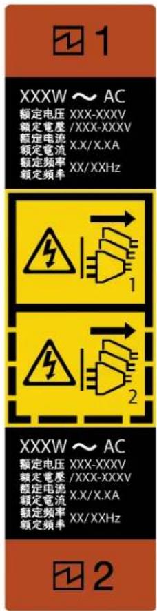
Figure 109. Hot-swap power supply label
Attention: This type of power supply is hot-swap only when two power supplies are installed for redundancy. If only one power supply is installed, you must power off the server first before removing the power supply.
The following tips describe the information that you must consider when you remove a power supply with dc input.
CAUTION:
240 V dc input (input range: 180-300 V dc) is supported in China ONLY. Power supply with 240 V dc input cannot support hot plugging power cord function. Before removing the power supply with dc input, please turn off server or disconnect dc power sources at the breaker panel or by turning off the power source. Then, remove the power cord.
Never remove the cover on a power supply or any part that has this label attached.
Hazardous voltage, current, and energy levels are present inside any component that has this label attached. There are no serviceable parts inside these components. If you suspect a problem with one of these parts, contact a service technician.
S019

CAUTION:
The power-control button on the device does not turn off the electrical current supplied to the device. The device also might have more than one connection to dc power. To remove all electrical current from the device, ensure that all connections to dc power are disconnected at the dc power input terminals.
S029


DANGER
Electrical current from power, telephone, and communication cables is hazardous. To avoid a shock hazard:
- Do not connect or disconnect any cables or perform installation, maintenance, or reconfiguration of this product during an electrical storm.
- Connect all power cords to a properly wired and grounded power source.
- Connect to properly wired power sources any equipment that will be attached to this product.
- When possible, use one hand only to connect or disconnect signal cables.
- Never turn on any equipment when there is evidence of fire, water, or structural damage.
- Disconnect the attached ac power cords, dc power sources, network connections, telecommunications systems, and serial cables before you open the device covers, unless you are instructed otherwise in the installation and configuration procedures.
- Connect and disconnect cables as described in the following table when you install, move, or open covers on this product or attached devices.
To Connect: To Disconnect:
- Turn OFF all power sources and equipment that is to be attached to this product.
- Attach signal cables to the product.
- Attach power cords to the product.
- For ac systems, use appliance inlets.
- For dc systems, ensure correct polarity of -48 V dc connections: RTN is + and -48 V dc is -. Earth ground should use a two-hole lug for safety.
- Attach signal cables to other devices.
- Connect power cords to their sources.
-
Turn ON all the power sources.
-
Turn OFF all power sources and equipment that is to be attached to this product.
- For ac systems, remove all power cords from the chassis power receptacles or interrupt power at the ac power distribution unit.
- For dc systems, disconnect dc power sources at the breaker panel or by turning off the power source. Then, remove the dc cables.
- Remove the signal cables from the connectors.
- Remove all cables from the devices.
To remove a hot-swap power supply, complete the following steps:
Watch the procedure. A video of the removal process is available:
- Youtube: https://www.youtube.com/playlist?list=PLYV5R7hVcs-Acsjj4tU79GzKnWG316BYn
- Youku: http://list.youku.com/albumlist/show/id_50483452
Step 1. If the server is in a rack, pull back the cable management arm to gain access to the rear of the server and the power supply.
Step 2. Locate the failing power supply in the rear of your server.
Note: On each power supply, there are three status LEDs near the power cord connector. For information about the status LEDs, see “Rear view LEDs” on page 21.
Step 3. Disconnect the power cord from the failing hot-swap redundant power supply.
Note: If you are replacing two power supplies, do the power supply replacement one by one to ensure that the power supply to the server is not interrupted. Do not disconnect the power cord from the secondly replaced power supply until the power output LED for the firstly replaced power supply is lit.
Step 4. Press the release tab toward the handle and carefully pull the handle at the same time to slide the failing hot-swap power supply out of the chassis.

natural_image
Technical diagram of a mechanical or electrical component with internal channels and directional arrows (no text or symbols)Figure 110. Hot-swap power supply removal
After removing the power supply, do the following:
- Install a new power supply or install the power-supply filler to cover the power supply bay. See “Install a hot-swap power supply” on page 144.
- If you are instructed to return the old hot-swap power supply, follow all packaging instructions and use any packaging materials that are provided.
Install a hot-swap power supply
Use this information to install a hot-swap power supply.

Read the Installation Guidelines

ATTENTION: Static Sensitive Device Ground package before opening
The following tips describe the type of power supply that the server supports and other information that you must consider when you install a power supply:
- The standard shipping has only one power supply installed in the server. For redundancy and hot-swap support, you must install an additional hot-swap power supply. Certain customized models might be shipped with two power supplies installed.
- Ensure that the devices that you are installing are supported. For a list of supported optional devices for the server, go to: http://www.lenovo.com/serverproven/
Notes:
- Ensure that the two power supplies installed on the server have the same wattage.
- If you are replacing the existing power supply with a new power supply of different wattage, attach the power information label that comes with this option onto the existing label near the power supply.

Figure 111. Hot-swap power supply label
S035

CAUTION:
Never remove the cover on a power supply or any part that has this label attached.
Hazardous voltage, current, and energy levels are present inside any component that has this label attached. There are no serviceable parts inside these components. If you suspect a problem with one of these parts, contact a service technician.
S002

CAUTION:
Make sure all power cords are disconnected from system when reading in this manual and the following step is required to complete: Disconnect the power cords and all external cables from the rear of the enclosure.
S001


DANGER
Electrical current from power, telephone, and communication cables is hazardous.
To avoid a shock hazard:
- Do not connect or disconnect any cables or perform installation, maintenance, or reconfiguration of this product during an electrical storm.
- Connect all power cords to a properly wired and grounded electrical outlet.
- Connect to properly wired outlets any equipment that will be attached to this product.
- When possible, use one hand only to connect or disconnect signal cables.
- Never turn on any equipment when there is evidence of fire, water, or structural damage.
- Disconnect the attached power cords, telecommunications systems, networks, and modems before you open the device covers, unless instructed otherwise in the installation and configuration procedures.
- Connect and disconnect cables as described in the following table when installing, moving, or opening covers on this product or attached devices.
To Connect: To Disconnect:
- Turn everything OFF.
- First, attach all cables to devices.
- Attach signal cables to connectors.
- Attach power cords to outlet.
-
Turn device ON.
-
Turn everything OFF.
- First, remove power cords from outlet.
- Remove signal cables from connectors.
- Remove all cables from devices.
The following tips describe the information that you must consider when you install a power supply with dc input.
CAUTION:
240 V dc input (input range: 180-300 V dc) is supported in China ONLY. Power supply with 240 V dc input cannot support hot plugging power cord function. Before removing the power supply with dc input, please turn off server or disconnect dc power sources at the breaker panel or by turning off the power source. Then, remove the power cord.
警告:
Never remove the cover on a power supply or any part that has this label attached.
Hazardous voltage, current, and energy levels are present inside any component that has this label attached. There are no serviceable parts inside these components. If you suspect a problem with one of these parts, contact a service technician.
S019

CAUTION:
The power-control button on the device does not turn off the electrical current supplied to the device. The device also might have more than one connection to dc power. To remove all electrical current from the device, ensure that all connections to dc power are disconnected at the dc power input terminals.
S029


DANGER
Electrical current from power, telephone, and communication cables is hazardous.
To avoid a shock hazard:
- Do not connect or disconnect any cables or perform installation, maintenance, or reconfiguration of this product during an electrical storm.
- Connect all power cords to a properly wired and grounded power source.
- Connect to properly wired power sources any equipment that will be attached to this product.
- When possible, use one hand only to connect or disconnect signal cables.
- Never turn on any equipment when there is evidence of fire, water, or structural damage.
- Disconnect the attached ac power cords, dc power sources, network connections, telecommunications systems, and serial cables before you open the device covers, unless you are instructed otherwise in the installation and configuration procedures.
- Connect and disconnect cables as described in the following table when you install, move, or open covers on this product or attached devices.
To Connect: To Disconnect:
- Turn OFF all power sources and equipment that is to be attached to this product.
- Attach signal cables to the product.
-
Attach power cords to the product.
-
For ac systems, use appliance inlets.
-
For dc systems, ensure correct polarity of -48 V dc connections: RTN is + and -48 V dc is -. Earth ground should use a two-hole lug for safety.
-
Attach signal cables to other devices.
-
Connect power cords to their sources.
-
Turn ON all the power sources.
-
Turn OFF all power sources and equipment that is to be attached to this product.
- For ac systems, remove all power cords from the chassis power receptacles or interrupt power at the ac power distribution unit.
- For dc systems, disconnect dc power sources at the breaker panel or by turning off the power source. Then, remove the dc cables.
-
Remove the signal cables from the connectors.
-
Remove all cables from the devices.
Before installing a hot-swap power supply, touch the static-protective package that contains the new hot-swap power supply to any unpainted surface on the outside of the server. Then, take the new hot-swap power supply out of the package and place it on a static-protective surface.
To install a hot-swap power supply, complete the following steps:
Watch the procedure. A video of the installation process is available:
- Youtube: https://www.youtube.com/playlist?list=PLYV5R7hVcs-Acsjj4tU79GzKnWG316BYn
- Youku: http://list.youku.com/albumlist/show/id_50483452
Step 1. If there is a power-supply-bay filler installed, remove it.
Important: To ensure proper cooling during normal server operation, both of the power supply bays must be occupied. This means that each bay must have a power supply installed; or one has a power supply installed and the other has a power-supply filler installed.

natural_image
Technical diagram of a mechanical device with internal components and directional arrow (no text or symbols)Figure 112. Hot-swap power supply filler removal
Step 2. Slide the new hot-swap power supply into the bay until it snaps into position.

natural_image
Isometric technical diagram of a computer tower with visible fan and socket (no text or labels)Figure 113. Hot-swap power supply installation
After installing the hot-swap power supply:
- Connect the power cable to the power supply and a properly grounded electrical outlet.
- If the server is powered off, power on the server. Ensure that both the power input LED and the power output LED on the power supply are lit, indicating that the power supply is operating properly.
Power interface board replacement
Use this information to remove and install the power interface board.
Note: This section applies only to server models that have the power interface board installed.
Remove the power interface board
Use this information to remove the power interface board.

Read the Installation Guidelines

Power Off
the server
for this task

ATTENTION: Static Sensitive Device Ground package before opening
Before removing the power interface board:
- If the server is installed in a rack, remove the server from the rack.
- Remove the server cover. See "Remove the server cover" on page 63.
- Remove the air baffle. See "Remove the air baffle" on page 67.
- Remove all hot-swap power supplies. See "Remove a hot-swap power supply" on page 139.
- Disconnect all cables from the power interface board.
To remove the power interface board, complete the following steps:
Watch the procedure. A video of the removal process is available:
- Youtube: https://www.youtube.com/playlist?list=PLYV5R7hVcs-Acsjj4tU79GzKnWG316BYn
- Youku: http://list.youku.com/albumlist/show/id_50483452

Figure 114. Power interface board removal
Step 1. Remove the screw that secures the power interface board.
Step 2. Gently lift the power interface board upward so that the power interface board is disengaged from the mounting stud on the chassis. Then, carefully remove the power interface board out of the chassis.
If you are instructed to return the old power interface board, follow all packaging instructions and use any packaging materials that are provided.
Install the power interface board
Use this information to install the power interface board.

Before installing the power interface board, touch the static-protective package that contains the new power interface board to any unpainted surface on the outside of the server. Then, take the new power interface board out of the package and place it on a static-protective surface.
To install the power interface board, complete the following steps:
Watch the procedure. A video of the installation process is available:
- Youtube: https://www.youtube.com/playlist?list=PLYV5R7hVcs-Acsjj4tU79GzKnWG316BYn
- Youku: http://list.youku.com/albumlist/show/id_50483452
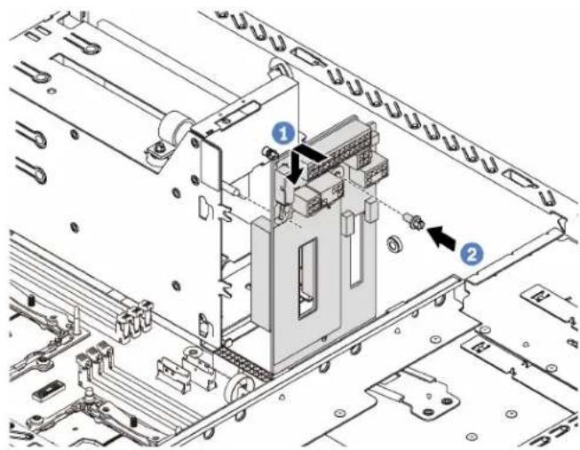
Figure 115. Power interface board installation
Step 1. Insert the hole in the power interface board into the corresponding mounting stud on the chassis. Then, gently move the power interface board downward so that it is engaged with the mounting stud.
Step 2. Install the screw to secure the power interface board in place.
After installing the power interface board:
- Reconnect all cables to the power interface board. See "Power interface board" on page 33.
- Complete the parts replacement. See "Complete the parts replacement" on page 170.
Hot-swap power supply cage replacement
Use this information to remove and install the hot-swap power supply cage.
Note: This section applies only to server models that have the hot-swap power supply cage installed.
Remove the hot-swap power supply cage
Use this information to remove the hot-swap power supply cage.

Read the Installation Guidelines

Power Off
the server
for this task

ATTENTION: Static Sensitive Device Ground package before opening
Before removing the hot-swap power supply cage:
- If the server is installed in a rack, extend the server from the rack.
- Remove the server cover. See "Remove the server cover" on page 63.
- Remove the air baffle. See "Remove the air baffle" on page 67.
- Remove the hot-swap power supplies. See "Remove a hot-swap power supply" on page 139.
- Remove the power interface board. See "Remove the power interface board" on page 149.
To remove the hot-swap power supply cage, complete the following steps:
Watch the procedure. A video of the removal process is available:
- Youtube: https://www.youtube.com/playlist?list=PLYV5R7hVcs-Acsjj4tU79GzKnWG316BYn
- Youku: http://list.youku.com/albumlist/show/id_50483452

Figure 116. Hot-swap power supply cage removal
Step 1. Remove the screws that secure the hot-swap power supply cage.
Step 2. Push the hot-swap power supply cage toward the front of the server. Then, remove the hot-swap power supply cage out of the chassis.
Install the hot-swap power supply cage
Use this information to install the hot-swap power supply cage.

Read the Installation Guidelines
Power Off
the server
for this task

ATTENTION: Static Sensitive Device Ground package before opening
Before installing the hot-swap power supply cage, touch the static-protective package that contains the new hot-swap power supply cage to any unpainted surface on the outside of the server. Then, take the new cage out of the package and place them on a static-protective surface.
To install the hot-swap power supply cage, complete the following steps:
Watch the procedure. A video of the installation process is available:
- Youtube: https://www.youtube.com/playlist?list=PLYV5R7hVcs-Acsjj4tU79GzKnWG316BYn
- Youku: http://list.youku.com/albumlist/show/id_50483452
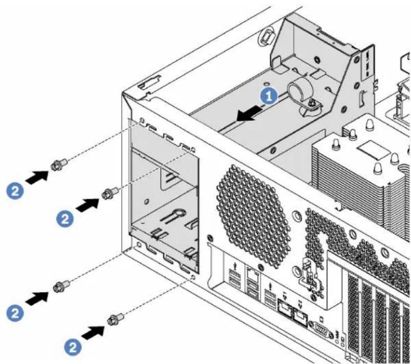
Figure 117. Hot-swap power supply cage installation
Step 1. Slide the new hot-swap power supply cage into the bay as shown until it snaps into position.
Step 2. Install the screws to secure the hot-swap power supply cage.
After installing the hot-swap power supply cage:
-
Install the power interface board. See "Install the power interface board" on page 150.
-
Install the hot-swap power supplies. See "Install a hot-swap power supply" on page 144.
-
Complete the parts replacement. See "Complete the parts replacement" on page 170.
Processor and heat sink replacement
Use the following procedures to replace an assembled processor and heat sink, known as a processor-heat-sink module (PHM), a processor, or a heat sink.
Attention: Before you begin replacing a processor, make sure that you have an alcohol cleaning pad (part number 00MP352) and blue thermal grease (part number 01KP765). Do not use gray thermal grease (part number 41Y9292) when replacing a ThinkSystem ST550 processor.
Important: The processor in your server can throttle, temporarily lowering speed to reduce heat output, in response to thermal conditions. In instances where the throttling period is of extremely short duration (100 ms or less), the only indication will be an entry in the event log. In these instances the event can be ignored and processor replacement is not required.
Remove a processor and heat sink
Processors are in the compute system boards that are accessed from the front of the server. This task has instructions for removing an assembled processor and heat sink, known as a processor-heat-sink module (PHM), a processor, and a heat sink. All of these tasks require a Torx T30 driver.

Read the Installation Guidelines

Power Off the server for this task

ATTENTION: Static Sensitive Device Ground package before opening
Attention:
- Each processor socket must always contain a cover or a PHM. When removing or installing a PHM, protect empty processor sockets with a cover.
- Do not touch the processor socket or processor contacts. Processor-socket contacts are very fragile and easily damaged. Contaminants on the processor contacts, such as oil from your skin, can cause connection failures.
- Remove and install only one PHM at a time. If the system board supports multiple processors, install the PHMs starting with the first processor socket.
- Do not allow the thermal grease on the processor or heat sink to come in contact with anything. Contact with any surface can compromise the thermal grease, rendering it ineffective. Thermal grease can damage components, such as electrical connectors in the processor socket. Do not remove the grease cover from a heat sink until you are instructed to do so.
Before removing a PHM:
Note: The heat sink, processor, and processor retainer for your system might be different than those shown in the illustrations.
- If the server is installed in a rack, extend the server from the rack.
- Remove the server cover. See "Remove the server cover" on page 63.
- Remove the air baffle. See "Remove the air baffle" on page 67.
- Remove any parts and disconnect any cables that might impede your access to the PHM.
To remove a PHM, complete the following steps:
Watch the procedure. A video of the removal process is available:
- Youtube: https://www.youtube.com/playlist?list=PLYV5R7hVcs-Acsjj4tU79GzKnWG316BYn
- Youku: http://list.youku.com/albumlist/show/id_50483452
Step 1. Remove the PHM from the system board.

Figure 118. Removing a PHM
Attention: To prevent damage to components, make sure that you follow the indicated loosening sequence.
a. Fully loosen the Torx T30 captive fasteners on the processor-heat-sink module in the removal sequence shown on the heat-sink label.
b. Lift the processor-heat-sink module from the processor socket.
After removing a PHM:
- If you are removing the PHM as part of a system board replacement, set the PHM aside.
- If you are removing the PHM, remove the extra system fans accordingly and install fan fillers to cover the place. For information about the system fan configuration, see "Specifications" on page 3.
- If you are replacing the processor or heat sink, separate the processor and its retainer from the heat sink.
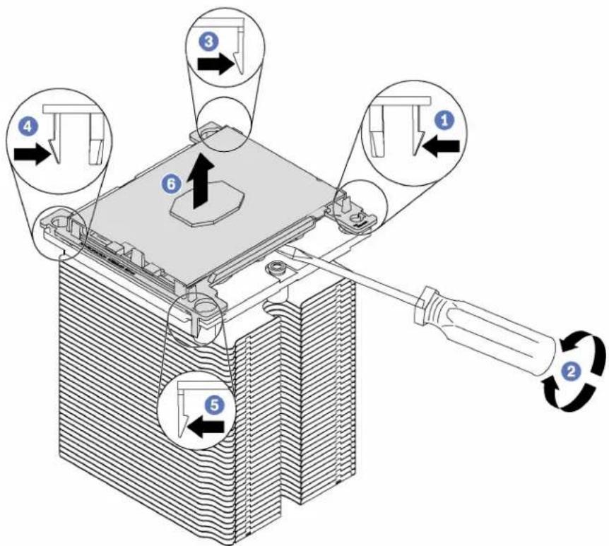
Figure 119. Separating a heat sink from a processor
-
Press the retaining clip at the corner of the processor retainer closest to the pry point; then, gently pry this corner of the retainer away from the heat sink with a flat-bladed screwdriver, using a twisting motion to break the processor-to-heat-sink seal.
-
Release the remaining retaining clips and lift the processor and retainer from the heat sink.
-
After separating the processor and retainer from the heat sink, hold the processor and retainer with the thermal-grease side down and the processor-contact side up to prevent the processor from falling out of the retainer.
Note: The processor retainer will be removed and discarded in a later step and replaced with a new one.
- If you are replacing the processor, you will be reusing the heat sink. Wipe the thermal grease from the bottom of the heat sink using an alcohol cleaning pad.
- If you are replacing the heat sink, you will be reusing the processor. Wipe the thermal grease from the top of the processor using an alcohol cleaning pad.
If you are instructed to return the old processor or heat sink, follow all packaging instructions and use any packaging materials that are provided.
Install a processor and heat sink
This task has instructions for installing an assembled processor and heat sink, known as a processor-heat-sink module (PHM), a processor, and a heat sink. All of these tasks require a Torx T30 driver.

Read the Installation Guidelines

Power Off
the server
for this task

ATTENTION: Static Sensitive Device Ground package before opening
Attention:
- Each processor socket must always contain a cover or a PHM. When removing or installing a PHM, protect empty processor sockets with a cover.
- Do not touch the processor socket or processor contacts. Processor-socket contacts are very fragile and easily damaged. Contaminants on the processor contacts, such as oil from your skin, can cause connection failures.
- Remove and install only one PHM at a time. If the system board supports multiple processors, install the PHMs starting with the first processor socket.
- Do not allow the thermal grease on the processor or heat sink to come in contact with anything. Contact with any surface can compromise the thermal grease, rendering it ineffective. Thermal grease can damage components, such as electrical connectors in the processor socket. Do not remove the grease cover from a heat sink until you are instructed to do so.
Notes:
- PHMs are keyed for the socket where they can be installed and for their orientation in the socket.
- See http://www.lenovo.com/serverproven/ for a list of processors supported for your server. All processors on the system board must have the same speed, number of cores, and frequency.
- Before you install a new PHM or replacement processor, update your system firmware to the latest level. See “Firmware updates” on page 7.
- Installing an additional PHM can change the memory requirements for your system. See “DIMM installation rules” on page 106 for a list of processor-to-memory relationships.
- Optional devices available for your system might have specific processor requirements. See the documentation that comes with the optional device for information.
Before installing a PHM:
Note: The heat sink, processor, and processor retainer for your system might be different than those shown in the illustrations.
- Remove the existing PHM, if one is installed. See "Remove a processor and heat sink" on page 154.
- Replace the processor retainer of the replacement processor.
Note: Replacement processors come with both rectangular and square processor retainers. A rectangular retainer comes attached to the processor. You must remove the rectangular retainer and replace it with a square retainer. The rectangular retainer can be discarded.
a. Remove the rectangular processor retainer.
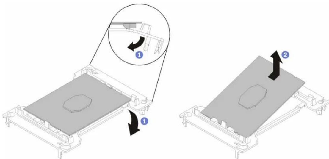
Figure 120. Removing a processor retainer
Note: When the processor is out of its retainer, hold the processor by the long edges to prevent touching the contacts or the thermal grease, if it is applied.
With the processor-contact side up, flex the ends of the retainer down and away from the processor to release the retaining clips; then, remove the processor from the retainer. Discard the old retainer.
b. Install the square retainer.

Figure 121. Installing a processor retainer
1) Position the processor on the new retainer so that the triangular marks align; then, insert the unmarked end of the processor into the retainer.
2) Holding the inserted end of the processor in place, flex the opposite end of the retainer down and away from the processor until you can press the processor under the clip on the retainer. To prevent the processor from falling out of the retainer after it is inserted, keep the processor-contact side up and hold the processor-retainer assembly by the sides of the retainer.
3) If there is any old thermal grease on the processor, gently clean the top of the processor using an alcohol cleaning pad.
- If you are replacing a processor:
a. Remove the processor identification label from the heat sink and replace it with the new label that comes with the replacement processor.
b. Apply new thermal grease (1/2-syringe, 0.65 g) to the top of the new processor.
Attention: Use only blue thermal grease (part number 01KP765) when replacing the processor. Do not use gray thermal grease (part number 41Y9292).

natural_image
Technical line drawing of a rectangular electronic component with mounting holes and a central irregular shape (no text or symbols)Figure 122. Thermal grease application
1) Carefully place the processor and retainer on a flat surface with the processor-contact side down.
2) Apply half a syringe of thermal grease, approximately 0.65 g, to the center of the processor top.
- If you are replacing a heat sink, remove the processor identification label from the old heat sink and place it on the new heat sink in the same location. The label is on the side of the heat sink closet to the triangular alignment mark.
If you are unable to remove the label and place it on the new heat sink, or if the label is damaged during transfer, write the processor serial number from the processor identification label on the new heat sink in the same location as the label would be placed using a permanent marker.
- Assemble the processor and heat sink, if these components are separate.
Notes:
- If you are replacing a heat sink, remove the heat sink from its shipping tray and place the processor and retainer in the opposite half of the heat sink shipping tray with the processor-contact side down. To prevent the processor from falling out of the retainer, hold the processor-retainer assembly by its sides with the processor-contact side up until you turn it over to fit in the shipping tray.
- If you are replacing a processor where you have changed the processor retainer, you will install the heat sink onto the processor and retainer outside of the shipping tray. To prevent the processor from falling out of the retainer, hold the processor-retainer assembly by its sides with the processor-contact side.
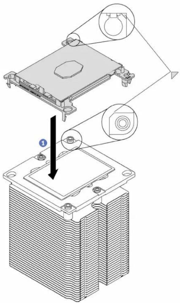
natural_image
Technical illustration of a heat sink assembly with cooling fins and housing (no text or symbols)
Figure 123. Assembling a PHM outside of a shipping tray
a. Align the triangular marks on the processor retainer and the heat sink or align the triangular mark on the processor retainer with the notched corner of the heat sink.
b. Insert the processor-retainer clips into the holes on the heat sink.
c. Press the retainer into place until the clips at all four corners engage.
To install a PHM, complete the following steps:
Watch the procedure. A video of the installation process is available:
- Youtube: https://www.youtube.com/playlist?list=PLYV5R7hVcs-Acsjj4tU79GzKnWG316BYn
- Youku: http://list.youku.com/albumlist/show/id_50483452
Step 1. Remove the processor socket cover, if one is installed on the processor socket, by placing your fingers in the half-circles at each end of the cover and lifting it from the system board.
Step 2. Install the processor-heat-sink module on the system board.

Figure 124. Installing a PHM
a. Align the triangular marks and guide pins on the processor socket with the PHM; then, insert the PHM into the processor socket.
Attention: To prevent damage to components, make sure that you follow the indicated tightening sequence.
b. Fully tighten the Torx T30 captive fasteners in the installation sequence shown on the heat-sink label. Tighten the screws until they stop; then, visually inspect to make sure that there is no gap between the screw shoulder beneath the heat sink and the microprocessor socket. (For reference, the torque required for the nuts to fully tighten is 1.4 — 1.6 newton-meters, 12 — 14 inch-pounds).
After installing a PHM:
- Complete the parts replacement. See "Completing the parts replacement" on page 170.
System board replacement
Use this information to remove and install the system board.
S017

CAUTION:
Hazardous moving fan blades nearby.
S012

CAUTION:
Hot surface nearby.
Remove the system board
Use this information to remove the system board.

Read the Installation Guidelines

Power Off the server for this task

ATTENTION: Static Sensitive Device Ground package before opening
Before removing the system board:
- If the server is installed in a rack, extend the server from the rack.
- Remove the server cover. See "Remove the server cover" on page 63.
- Record where the cables are connected to the system board; then, disconnect all the cables.
Attention: Disengage all latches, cable clips, release tabs, or locks on cable connectors beforehand. Failing to release them before removing the cables will damage the cable connectors on the system board. Any damage to the cable connectors may require replacing the system board.
-
Remove any of the following components that are installed on the system board and put them in a safe, static-protective place. See the related topics in Chapter 3 "Hardware replacement procedures" on page 55.
-
System fans
- DIMMs
- PCIe adapters
- M.2 backplane
- Serial port module
- CMOS battery
• TCM (for China only) - Intrusion switch
- PHM
Important: Do not disassemble the PHM.
To remove the system board, complete the following steps:
Watch the procedure. A video of the removal process is available:
- Youtube: https://www.youtube.com/playlist?list=PLYV5R7hVcs-Acsjj4tU79GzKnWG316BYn
- Youku: http://list.youku.com/albumlist/show/id_50483452
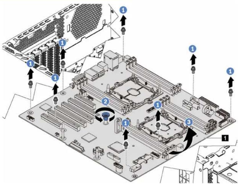
Figure 125. System board removal
Step 1. Remove the eight screws that secure the system board. Put the screws in a safe place.
Step 2. Loosen the thumb screw.
Step 3. Gently lift the thumb screw and grasp the system board by its edge to remove the system board in the direction as shown.
Install the system board
Use this information to install the system board.

Read the Installation Guidelines

Power Off
the server
for this task

ATTENTION: Static Sensitive Device Ground package before opening
Before installing the system board, touch the static-protective package that contains the new system board to any unpainted surface on the outside of the server. Then, take the new system board out of the package and place it on a static-protective surface.
To install the system board, complete the following steps:
Watch the procedure. A video of the installation process is available:
- Youtube: https://www.youtube.com/playlist?list=PLYV5R7hVcs-Acsjj4tU79GzKnWG316BYn
- Youku: http://list.youku.com/albumlist/show/id_50483452
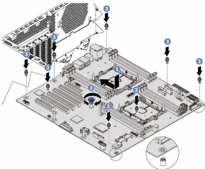
Figure 126. System board installation
Step 1. Gently lower the system board into the chassis. Then, move the system board toward the rear of the server. Ensure that the rear connectors on the new system board are inserted into the corresponding holes in the rear panel.
Step 2. Tighten the thumb screw.
Step 3. Install the eight screws to secure the system board in place.
After installing the system board:
- Install any components that you removed from the failing system board. See the related topics in Chapter 3 "Hardware replacement procedures" on page 55.
- Complete the parts replacement. See "Complete the parts replacement" on page 170.
- Update the Universal Unique Identifier (UUID). See "Update the Universal Unique Identifier (UUID)" on page 164.
- Update the SMBIOS/DMI information. See "Update the DMI/SMBIOS data" on page 166.
- Enable TPM/TCM. See "Enable TPM/TCM" on page 168.
- Optionally, enable Secure Boot.
Update the Universal Unique Identifier (UUID)
The Universal Unique Identifier (UUID) must be updated when the system board is replaced. Use the Lenovo XClarity Essentials OneCLI to update the UUID in the UEFI-based server. Lenovo XClarity Essentials OneCLI is an online tool that supports several operating systems; make sure that you download the version for your operating system.
Notes: You can use Lenovo XClarity Provisioning Manager to update the UUID for the server:
- Start the server and press F1 to display the Lenovo XClarity Provisioning Manager system setup interface.
- From the System Summary page, click Update VPD.
3. Update the UUID.
To download Lenovo XClarity Essentials OneCLI, go to the following site:
https://datacentersupport.lenovo.com/us/en/solutions/HT116433
Lenovo XClarity Essentials OneCLI sets the UUID in the Lenovo XClarity Controller. Select one of the following methods to access the Lenovo XClarity Controller and set the UUID:
- Online from the target system, such as LAN or keyboard console style (KCS) access
- Remote access to the target system (LAN based)
Step 1. Copy and unpack the OneCLI package, which also includes other required files, to the server. Make sure that you unpack the OneCLI and the required files to the same directory.
Step 2. After you have OneCLI in place, use the following command syntax to set the UUID:
onecli config set SYSTEM_PROD_DATA.SysInfoUUID
Where:
Up to 16-byte hexadecimal value assigned by you.
[access_method]
The access method that you selected to use from the following methods:
- Online authenticated LAN access, type the command:
Example that does not use the user ID and password default values: onecli config set SYSTEM_PROD_DATA.SYsInfoUUID
Example that uses the user ID and password default values: onecli config set SYSTEM_PROD_DATA.SysInfoUUID
- Online KCS access (unauthenticated and user restricted):
You do not need to specify a value for access_method when you use this access method.
Example:
onecli config set SYSTEM_PROD_DATA.SysInfoUUID
Note: The KCS access method uses the IPMI/KCS interface, which requires that the IPMI driver be installed.
- Remote LAN access, type the command:
Note: When using the remote LAN access method to access Lenovo XClarity Controller using the LAN from a client, the host and the bmc_external_ip address are required parameters.
[--bmc bmc_user_id:bmc_password@bmc_externaln_ip]
Where:
bmc_external_ip
The external BMC (Lenovo XClarity Controller) LAN IP address. There is no default value. This parameter is required.
bmc_user_id
The BMC (Lenovo XClarity Controller) account (1 of 12 accounts). The default value is USERID.
bmc_password
The BMC (Lenovo XClarity Controller) account password (1 of 12 accounts). The default value is PASSWORD (with a zero 0 not an O).
Example that does not use the user ID and password default values:
onecli config set SYSTEM_PROD_DATA.SYsInfoUUID
[--bmc bmc_user_id:bmc_password@bmc_internal_ip]
Example that does use the user ID and password default values:
onecli config set SYSTEM_PROD_DATA.SysInfoUUID
Step 3. Restart the Lenovo XClarity Controller.
Step 4. Restart the server.
Update the DMI/SMBIOS data
The Desktop Management Interface (DMI) must be updated when the system board is replaced. Use the Lenovo XClarity Essentials OneCLI to update the DMI in the UEFI-based server. Lenovo XClarity Essentials OneCLI is an online tool that supports several operating systems; make sure that you download the version for your operating system.
Notes: You can use Lenovo XClarity Provisioning Manager to update the asset tag for the server:
- Start the server and press F1 to display the Lenovo XClarity Provisioning Manager system setup interface.
- From the System Summary page, click Update VPD.
- Update the asset tag information.
To download Lenovo XClarity Essentials OneCLI, go to the following site:
https://datacentersupport.lenovo.com/us/en/solutions/HT116433
Lenovo XClarity Essentials OneCLI sets the DMI in the Lenovo XClarity Controller. Select one of the following methods to access the Lenovo XClarity Controller and set the DMI:
- Online from the target system, such as LAN or keyboard console style (KCS) access
- Remote access to the target system (LAN based)
Step 1. After you have Lenovo XClarity Essentials OneCLI in place, type the following commands to set the DMI:
onecli config set SYSTEM_PROD_DATA.SysInfoProdName <m/t_model> [access_method]
onecli config set SYSTEM_PROD_DATA.SysInfoSerialNum <s/n> [access_method]
onecli config set SYSTEM_PROD_DATA.SysEncloseAssetTag <asset_tag> [access_method]
Where:
<m/t_model>
The server machine type and model number. Type mtm xxxxyyy, where xxxx is the machine type and yyy is the server model number.
The serial number on the server. Type sn zzzzzzz, where zzzzzzz is the serial number.
The server asset tag number. Type asset aaaaaaaaaaaaaaaaaaaaaaaaaaaaaaaa, where aaaaaaaaaaaaaaaaaaaaaaaaaaaaaaaaaaaaaa is the asset tag number.
[access_method]
The access method that you select to use from the following methods:
- Online authenticated LAN access, type the command: [--bmc bmc_user_id:bmc_password@bmc_internal_ip]
Where:
bmc_internal_ip
The BMC (Lenovo XClarity Controller) internal LAN/USB IP address. The default value is 169.254.95.118.
bmc_user_id
The BMC account (1 of 12 accounts). The default value is USERID.
bmc_password
The BMC account password (1 of 12 accounts). The default value is PASSWORD (with a zero 0 not an O).
Note: If you do not specify any of these parameters, OneCLI will use the default values. When the default values are used and OneCLI is unable to access the Lenovo XClarity Controller using the online authenticated LAN access method, OneCLI will automatically use the unauthenticated KCS access method.
Examples that do use the user ID and password default values:
onecli config set SYSTEM_PROD_DATA.SysInfoProdName
onecli config set SYSTEM_PROD_DATA.SysEncloseAssetTag
- Online KCS access (unauthenticated and user restricted): You do not need to specify a value for access_method when you use this access method.
Note: The KCS access method uses the IPMI/KCS interface, which requires that the IPMI driver be installed.
The following commands are examples of not using the user ID and password default values:
onecli config set SYSTEM_PROD_DATA.SysInfoProdName
onecli config set SYSTEM_PROD_DATA.SysEncloseAssetTag
- Remote LAN access, type the command:
Note: When using the remote LAN access method to access Lenovo XClarity Controller using the LAN from a client, the host and the bmc_external_ip address are required parameters.
[--bmc bmc_user_id:bmc_password@bmc_external_ip]
Where:
bmc_external_ip
The external BMC (Lenovo XClarity Controller) LAN IP address. There is no default value. This parameter is required.
bmc_user_id
The BMC account (1 of 12 accounts). The default value is USERID.
bmc_password
The BMC account password (1 of 12 accounts). The default value is PASSWORD (with a zero 0 not an O).
Examples that do use the user ID and password default values:
onecli config set SYSTEM_PROD_DATA.SysInfoProdName
onecli config set SYSTEM_PROD_DATA.SysInfoSerialNum --host
onecli config set SYSTEM_PROD_DATA.SysEncloseAssetTag
Step 2. Restart the server.
Enable TPM/TCM
The server supports Trusted Platform Module (TPM), Version 1.2 or Version 2.0.
Note: For customers in the People's Republic of China, TPM is not supported. However, customers in the People's Republic of China can install a Trusted Cryptographic Module (TCM) adapter (sometimes called a daughter card).
When a system board is replaced, you must make sure that the TPM/TCM policy is set correctly.
CAUTION:
Take special care when setting the TPM/TCM policy. If it is not set correctly, the system board can become unusable.
Set the TPM/TCM policy
By default, a replacement system board is shipped with the TPM/TCM policy set to undefined. You must modify this setting to match the setting that was in place for the system board that is being replaced.
You can set the TPM/TCM policy from Lenovo XClarity Provisioning Manager.
Complete the following steps to set the TPM/TCM policy.
Step 1. Start the server and when prompted, press F1 to display Lenovo XClarity Provisioning Manager.
Step 2. If the power-on Administrator password is required, enter the password.
Step 3. From the System Summary page, click Update VPD.
Step 4. Set the policy to one of the following settings.
- TCM enabled - China only. Customers in the People's Republic of China should choose this setting if a TCM adapter is installed.
- TPM enabled - ROW. Customers outside of the People's Republic of China should choose this setting.
- Permanently disabled. Customers in the People's Republic of China should use this setting if no TCM adapter is installed.
Although the setting undefined is available as a policy setting, it should not be used.
Assert Physical Presence
Before you can assert Physical Presence, the Physical Presence Policy must be enabled. By default, the Physical Presence Policy is enabled with a timeout of 30 minutes.
If the Physical Presence Policy is enabled, you can assert Physical Presence through the Lenovo XClarity Controller or through hardware jumpers on the system board.
Notes: If the Physical Presence Policy has been disabled:
- Set the hardware Physical Presence jumper on the system board to assert Physical Presence.
- Enable the Physical Presence Policy using either F1 (UEFI Settings) or Lenovo XClarity Essentials OneCLI.
Assert Physical Presence through the Lenovo XClarity Controller
Complete the following steps to assert Physical Presence through the Lenovo XClarity Controller:
- Log in to the Lenovo XClarity Controller interface.
For information about logging in to the Lenovo XClarity Controller, see:
http://sysmgt.lenovofiles.com/help/topic/com.lenovo.systems.management.xcc.doc/dw1lm_c_chapter2_openingandusing.html
- Click BMC Configuration → Security and verify that Physical Presence is set to assert.
Assert Physical Presence through the hardware
You can also assert hardware Physical Presence through the use of a jumper on the system board. For more information about asserting hardware Physical Presence through the use of a jumper, see “System board jumpers” on page 25.
Set the TPM version
To set the TPM version, Physical Presence must be asserted.
For information about accessing the Lenovo XClarity Controller interface, see:
http://sysmgt.lenovofiles.com/help/topic/com.lenovo.systems.management.xcc.doc/dw1lm_c_chapter2_openingandusing.html
To set the TPM version:
- Download and install Lenovo XClarity Essentials OneCLI.
a. Go to http://datacentersupport.lenovo.com and navigate to the support page for your server.
b. Click Drivers & Software.
c. Navigate to the version of Lenovo XClarity Essentials OneCLI for your operating system and download the package.
- Run the following command to set the TPM version:
Note: You can change the TPM version from 1.2 to 2.0 and back again. However, you can toggle between versions a maximum of 128 times.
To set the TPM version to version 2.0:
OneCli.exe config set TrustedComputingGroup.DeviceOperation "Update to TPM2.0 compliant" --bmc userid:password@ip_address
To set the TPM version to version 1.2:
OneCli.exe config set TrustedComputingGroup.DeviceOperation "Update to TPM1.2 compliant" --bmc userid:password@ip_address
where:
: are the credentials used to access the BMC (Lenovo XClarity Controller interface) of your server. The default user ID is USERID, and the default password is PASSWORD (zero, not an uppercase o) -
For more information about the Lenovo XClarity Essentials OneCLI set command, see: http://sysmgt.lenovofiles.com/help/topic/toolsctr_cli_lenovo/onecli_r_set_command.html -
Alternatively, you can use the following Advanced Settings Utility (ASU) commands:
To set the TPM version to version 2.0:
asu64 set TPMVersion.TPMVersion "Update to TPM2.0 compliant" --host
To set the TPM version to version 1.2:
asu64 set TPMVersion.TPMVersion "Update to TPM1.2 compliant" --host
where:
and are the credentials used to the BMC (Lenovo XClarity Controller interface) of your server. The default user ID is USERID, and the default password is PASSWORD (zero, not an uppercase o)
Enable UEFI Secure Boot
Optionally, you can enable UEFI Secure Boot.
Physical Presence must be asserted if you are going to enable UEFI Secure Boot. See “Assert Physical Presence” on page 168.
For information about accessing the Lenovo XClarity Controller interface, see:
http://sysmgt.lenovofiles.com/help/topic/com.lenovo.systems.management.xcc.doc/dw1lm_c_chapter2_openingandusing.html
There are two methods available to enable UEFI Secure Boot:
• From Lenovo XClarity Provisioning Manager
To enable UEFI Secure Boot from Lenovo XClarity Provisioning Manager:
- Start the server and when prompted, press F1 to display Lenovo XClarity Provisioning Manager.
- If the power-on Administrator password is required, enter the password.
- From the UEFI Setup page, click System Settings → Security → Secure Boot.
- Enable Secure Boot and save the settings.
• From Lenovo XClarity Essentials OneCLI
To enable UEFI Secure Boot from Lenovo XClarity Essentials OneCLI:
-
Download and install Lenovo XClarity Essentials OneCLI. To download Lenovo XClarity Essentials OneCLI, go to the following site: https://datacentersupport.lenovo.com/us/en/solutions/HT116433
-
Run the following command to enable Secure Boot:
OneCli.exe config set SecureBootConfiguration.SecureBootSetting Enabled --override --bmc
where:
: are the credentials used to access the BMC (Lenovo XClarity Controller interface) of your server. The default user ID is USERID, and the default password is PASSWORD (zero, not an uppercase o)
For more information about the Lenovo XClarity Essentials OneCLI set command, see: http://sysmgt.lenovofiles.com/help/topic/toolsctr_cli_lenovo/onecli_r_set_command.html
Complete the parts replacement
Use this information to complete the parts replacement.
To complete the parts replacement, do the following:
- Ensure that all components have been reassembled correctly and that no tools or loose screws are left inside your server.
- Properly route and secure the cables in the server. Refer to the cable connecting and routing information for each component.
- If you have removed the top cover, reinstall it. See "Install the server cover" on page 64.
- Reconnect external cables and power cords to the server.
Attention: To avoid component damage, connect the power cords last.
-
Update the server configuration if necessary.
-
Download and install the latest device drivers: http://datacentersupport.lenovo.com
- Update the system firmware. See "Firmware updates" on page 7.
- Update the UEFI configuration.
- Reconfigure the disk arrays if you have installed or removed a drive or a RAID adapter.
Chapter 4. Problem determination
Use the information in this section to isolate and resolve issues that you might encounter while using your server.
Lenovo servers can be configured to automatically notify Lenovo Support if certain events are generated. You can configure automatic notification, also known as Call Home, from management applications, such as the Lenovo XClarity Administrator. If you configure automatic problem notification, Lenovo Support is automatically alerted whenever a server encounters a potentially significant event.
To isolate a problem, you should typically begin with the event log of the application that is managing the server:
- If you are managing the server from the Lenovo XClarity Administrator, begin with the Lenovo XClarity Administrator event log.
- If you are managing the server from the Chassis Management Module 2, begin with the Chassis Management Module 2 event log.
- If you are using some other management application, begin with the Lenovo XClarity Controller event log.
Event logs
An alert is a message or other indication that signals an event or an impending event. Alerts are generated by the Lenovo XClarity Controller or by UEFI in the servers. These alerts are stored in the Lenovo XClarity Controller Event Log. If the server is managed by the Chassis Management Module 2 or by the Lenovo XClarity Administrator, alerts are automatically forwarded to those management applications.
Note: For a listing of events, including user actions that might need to be performed to recover from an event, see the Messages and Codes Reference, which is available at: http://thinksystem.lenovofiles.com/help/topic/7X09/pdf_files.html
Lenovo XClarity Administrator event log
If you are using Lenovo XClarity Administrator to manage server, network, and storage hardware, you can view the events from all managed devices through the XClarity Administrator.
Logs

Figure 127. Lenovo XClarity Administrator event log
For more information about working with events from XClarity Administrator, see:
http://sysmgt.lenovofiles.com/help/topic/com.lenovo.lxca.doc/events_vieweventlog.html
Lenovo XClarity Controller event log
The Lenovo XClarity Controller monitors the physical state of the server and its components using sensors that measure internal physical variables such as temperature, power-supply voltages, fan speeds, and component status. The Lenovo XClarity Controller provides various interfaces to systems management software and to system administrators and users to enable remote management and control of a server.
The Lenovo XClarity Controller monitors all components of the server and posts events in the Lenovo XClarity Controller event log.

Figure 128. Lenovo XClarity Controller event log
For more information about accessing the Lenovo XClarity Controller event log, see:
http://sysmgt.lenovofiles.com/help/topic/com.lenovo.systems.management.xcc.doc/event_log.html
General problem determination procedures
Use the information in this section to resolve problems if the event log does not contain specific errors or the server is inoperative.
If you are not sure about the cause of a problem and the power supplies are working correctly, complete the following steps to attempt to resolve the problem:
- Turn off the server.
- Ensure that the server is cabled correctly.
- Remove or disconnect the following devices, one at a time, until you find the failure. Turn on and configure the server each time you remove or disconnect a device.
- Any external devices
- Surge-suppressor device (on the server)
• Printer, mouse, and non-Lenovo devices - Each adapter
- Storage drives
- Memory modules until you reach the minimum configuration that is supported for the server
Note: The minimum configuration required for the server to start is one processor and one 8 GB DIMM.
- Turn on the server.
If the problem is solved when you remove an adapter from the server, but the problem recurs when you install the same adapter again, suspect the adapter. If the problem recurs when you replace the adapter with a different one, try a different PCIe slot.
If the problem appears to be a networking problem and the server passes all system tests, suspect a network cabling problem that is external to the server.
Resolving suspected power problems
Power problems can be difficult to solve. For example, a short circuit can exist anywhere on any of the power distribution buses. Usually, a short circuit will cause the power subsystem to shut down because of an overcurrent condition.
Complete the following steps to diagnose and resolve a suspected power problem.
Step 1. Check the event log and resolve any errors related to the power.
Note: Start with the event log of the application that is managing the server. For more information about event logs, see “Event logs” on page 173.
Step 2. Check for short circuits, for example, if a loose screw is causing a short circuit on a circuit board.
Step 3. Remove the adapters and disconnect the cables and power cords to all internal and external devices until the server is at the minimum configuration that is required for the server to start. See “Specifications” on page 3 to determine the minimum configuration for your server.
Step 4. Reconnect all ac power cords and turn on the server. If the server starts successfully, reseat the adapters and devices one at a time until the problem is isolated.
If the server does not start from the minimum configuration, replace the components in the minimum configuration one at a time until the problem is isolated.
Resolving suspected Ethernet controller problems
The method that you use to test the Ethernet controller depends on which operating system you are using. See the operating-system documentation for information about Ethernet controllers, and see the Ethernet controller device-driver readme file.
Complete the following steps to attempt to resolve suspected problems with the Ethernet controller.
Step 1. Make sure that the correct device drivers, which come with the server are installed and that they are at the latest level.
Step 2. Make sure that the Ethernet cable is installed correctly.
- The cable must be securely attached at all connections. If the cable is attached but the problem remains, try a different cable.
- If you set the Ethernet controller to operate at 100 Mbps or 1000 Mbps, you must use Category 5 cabling.
Step 3. Determine whether the hub supports auto-negotiation. If it does not, try configuring the integrated Ethernet controller manually to match the speed and duplex mode of the hub.
Step 4. Check the Ethernet controller LEDs on the rear panel of the server. These LEDs indicate whether there is a problem with the connector, cable, or hub.
- The Ethernet link status LED is lit when the Ethernet controller receives a link pulse from the hub. If the LED is off, there might be a defective connector or cable or a problem with the hub.
- The Ethernet transmit/receive activity LED is lit when the Ethernet controller sends or receives data over the Ethernet network. If the Ethernet transmit/receive activity is off, make sure that the hub and network are operating and that the correct device drivers are installed.
Step 5. Check the LAN activity LED on the rear of the server. The LAN activity LED is lit when data is active on the Ethernet network. If the LAN activity LED is off, make sure that the hub and network are operating and that the correct device drivers are installed.
Step 6. Check for operating-system-specific causes of the problem, and also make sure that the operating system drivers are installed correctly.
Step 7. Make sure that the device drivers on the client and server are using the same protocol.
If the Ethernet controller still cannot connect to the network but the hardware appears to be working, the network administrator must investigate other possible causes of the error.
Troubleshooting by symptom
Use this information to find solutions to problems that have identifiable symptoms.
To use the symptom-based troubleshooting information in this section, complete the following steps:
-
Check the event log of the application that is managing the server and follow the suggested actions to resolve any event codes.
-
If you are managing the server from the Lenovo XClarity Administrator, begin with the Lenovo XClarity Administrator event log.
- If you are using some other management application, begin with the Lenovo XClarity Controller event log.
For more information about event logs, see "Event logs" on page 173.
-
Review this section to find the symptoms that you are experiencing and follow the suggested actions to resolve the issue.
-
If the problem persists, contact support (see "Contacting Support" on page 193).
Power on and power off problems
Use this information to resolve issues when powering on or powering off the server.
- "Embedded hypervisor is not in the boot list" on page 177
- “The power button does not work (server does not start)” on page 177
- "Server does not power on" on page 178
- "Server does not power off" on page 178
Embedded hypervisor is not in the boot list
Complete the following steps until the problem is solved.
- If the server has been installed, moved, or serviced recently, or if this is the first time the embedded hypervisor is being used, make sure that the device is connected properly and that there is no physical damage to the connectors.
- See the documentation that comes with the optional embedded hypervisor flash device for setup and configuration information.
- Check http://www.lenovo.com/serverproven/ to validate that the embedded hypervisor device is supported for the server.
- Make sure that the embedded hypervisor device is listed in the list of available boot options. From the management controller user interface, click Server Configuration → Boot Options.
For information about accessing the management controller user interface, see the XClarity Controller product documentation:
http://sysmgt.lenovofiles.com/help/topic/com.lenovo.systems.management.xcc.doc/dw1lm_c_chapter2_openingandusing.html - Check http://datacentersupport.lenovo.com for any tech tips (service bulletins) related to the embedded hypervisor and the server.
- Make sure that other software works on the server to ensure that it is working properly.
The power button does not work (server does not start)
Note: The power button will not function until approximately 1 to 3 minutes after the server has been connected to ac power.
Complete the following steps until the problem is resolved:
- Make sure that the power button on the server is working correctly:
a. Disconnect the server power cords.
b. Reconnect the server power cords.
c. Reseat the operator information panel cable, and then repeat steps a and b. - If the server starts, reseat the operator information panel.
-
If the problem remains, replace the operator information panel.
-
Make sure that:
-
The power cords are correctly connected to the server and to a working electrical outlet.
-
The LEDs on the power supply do not indicate a problem.
-
Reseat the power supplies.
-
Replace each power supply, restarting the server each time:
• DIMMs
- Power supplies
- If you just installed an optional device, remove it, and restart the server. If the server starts, you might have installed more devices than the power supply supports.
Server does not power on
Complete the following steps until the problem is resolved:
- Check the event log for any events related to the server not powering on.
- Check for any LEDs that are flashing amber.
- Check the power LED on the system board.
- Reseat the power supply.
- Replace the power supply.
Server does not power off
Complete the following steps until the problem is resolved:
- Determine whether you are using an Advanced Configuration and Power Interface (ACPI) or a non-ACPI operating system. If you are using a non-ACPI operating system, complete the following steps:
a. Press Ctrl+Alt+Delete.
b. Turn off the server by pressing the power button and holding it down for 5 seconds.
c. Restart the server.
d. If the server fails POST and the power button does not work, disconnect the power cord for 20 seconds; then, reconnect the power cord and restart the server.
- If the problem remains or if you are using an ACPI-aware operating system, suspect the system board.
Memory problems
Use this information to resolve issues related to memory.
- “Displayed system memory less than installed physical memory” on page 178
- "Multiple rows of DIMMs in a branch identified as failing" on page 179
Displayed system memory less than installed physical memory
Complete the following steps until the problem is resolved:
Note: Each time you install or remove a DIMM, you must disconnect the server from the power source; then, wait 10 seconds before restarting the server.
-
Make sure that:
-
No error LEDs are lit on the operator information panel.
- No DIMM error LEDs are lit on the system board.
- Memory mirrored channel does not account for the discrepancy.
- The memory modules are seated correctly.
- You have installed the correct type of memory.
- If you changed the memory, you updated the memory configuration in the Setup utility.
- All banks of memory are enabled. The server might have automatically disabled a memory bank when it detected a problem, or a memory bank might have been manually disabled.
-
There is no memory mismatch when the server is at the minimum memory configuration.
-
Reseat the DIMMs, and then restart the server.
-
Run memory diagnostics. When you start a server and press F1, the Lenovo XClarity Provisioning Manager interface is displayed by default. You can perform memory diagnostics from this interface. From the Diagnostic page, click Run Diagnostic → Memory test.
-
Check the POST error log:
-
If a DIMM was disabled by a systems-management interrupt (SMI), replace the DIMM.
-
If a DIMM was disabled by the user or by POST, reseat the DIMM; then, run the Setup utility and enable the DIMM.
-
Reseat the DIMM.
-
Restart the server.
Multiple rows of DIMMs in a branch identified as failing
- Reseat the DIMMs; then, restart the server.
- Remove the lowest-numbered DIMM pair of those that are identified and replace it with an identical known good DIMM; then, restart the server. Repeat as necessary. If the failures continue after all identified DIMMs are replaced, go to step 4.
- Return the removed DIMMs, one at a time, to their original connectors, restarting the server after each DIMM, until a DIMM fails. Replace each failing DIMM with an identical known good DIMM, restarting the server after each DIMM replacement. Repeat step 3 until you have tested all removed DIMMs.
- Replace the lowest-numbered DIMM of those identified; then, restart the server. Repeat as necessary.
- Reverse the DIMMs between the channels (of the same processor), and then restart the server. If the problem is related to a DIMM, replace the failing DIMM.
- (Trained technician only) Replace the system board.
Hard disk drive problems
Use this information to resolve issues related to the hard disk drives.
- "Server cannot recognize a hard drive" on page 179
- "Multiple hard drives fail" on page 180
- "Multiple hard drives are offline" on page 180
- "A replacement hard disk drive does not rebuild" on page 180
- “Green hard disk drive activity LED does not represent actual state of associated drive” on page 181
- "Yellow hard disk drive status LED does not represent actual state of associated drive" on page 181
Server cannot recognize a hard drive
Complete the following steps until the problem is solved.
- Observe the associated yellow hard disk drive status LED. If the LED is lit, it indicates a drive fault.
- If the LED is lit, remove the drive from the bay, wait 45 seconds, and reinsert the drive, making sure that the drive assembly connects to the hard disk drive backplane.
- Observe the associated green hard disk drive activity LED and the yellow status LED:
- If the green activity LED is flashing and the yellow status LED is not lit, the drive is recognized by the controller and is working correctly. Run the diagnostics tests for the hard disk drives. When you start a server and press F1, the Lenovo XClarity Provisioning Manager interface is displayed by default. You can perform hard drive diagnostics from this interface. From the Diagnostic page, click Run Diagnostic → HDD test.
- If the green activity LED is flashing and the yellow status LED is flashing slowly, the drive is recognized by the controller and is rebuilding.
- If neither LED is lit or flashing, check the hard disk drive backplane.
-
If the green activity LED is flashing and the yellow status LED is lit, replace the drive. If the activity of the LEDs remains the same, go to step Hard disk drive problems. If the activity of the LEDs changes, return to step 1.
-
Make sure that the hard disk drive backplane is correctly seated. When it is correctly seated, the drive assemblies correctly connect to the backplane without bowing or causing movement of the backplane.
- Reseat the backplane power cable and repeat steps 1 through 3.
- Reseat the backplane signal cable and repeat steps 1 through 3.
-
Suspect the backplane signal cable or the backplane:
-
Replace the affected backplane signal cable.
-
Replace the affected backplane.
-
Run the diagnostics tests for the hard disk drives. When you start a server and press F1, the Lenovo XClarity Provisioning Manager interface is displayed by default. You can perform hard drive diagnostics from this interface. From the Diagnostic page, click Run Diagnostic → HDD test.
Based on those tests:
- If the adapter passes the test but the drives are not recognized, replace the backplane signal cable and run the tests again.
- Replace the backplane.
- If the adapter fails the test, disconnect the backplane signal cable from the adapter and run the tests again.
- If the adapter fails the test, replace the adapter.
Multiple hard drives fail
Complete the following steps until the problem is solved:
- View the Lenovo XClarity Controller event log for events related to power supplies or vibration issues and resolve those events.
- Make sure that the device drivers and firmware for the hard disk drive and server are at the latest level
Important: Some cluster solutions require specific code levels or coordinated code updates. If the device is part of a cluster solution, verify that the latest level of code is supported for the cluster solution before you update the code.
Multiple hard drives are offline
Complete the following steps until the problem is solved:
- View the Lenovo XClarity Controller event log for events related to power supplies or vibration issues and resolve those events.
- View the storage subsystem log for events related to the storage subsystem and resolve those events.
A replacement hard disk drive does not rebuild
Complete the following steps until the problem is solved:
- Make sure that the hard disk drive is recognized by the adapter (the green hard disk drive activity LED is flashing).
- Review the SAS/SATA RAID adapter documentation to determine the correct configuration parameters and settings.
Green hard disk drive activity LED does not represent actual state of associated drive
Complete the following steps until the problem is solved:
- If the green hard disk drive activity LED does not flash when the drive is in use, run the diagnostics tests for the hard disk drives. When you start a server and press F1, the Lenovo XClarity Provisioning Manager interface is displayed by default. You can perform hard drive diagnostics from this interface. From the Diagnostic page, click Run Diagnostic → HDD test.
- If the drive passes the test, replace the backplane.
- If the drive fails the test, replace the drive.
Yellow hard disk drive status LED does not represent actual state of associated drive
Complete the following steps until the problem is solved:
- Turn off the server.
- Reseat the SAS/SATA adapter.
- Reseat the backplane signal cable and backplane power cable.
- Reseat the hard disk drive.
- Power on the server and observe the activity of the hard disk drive LEDs.
Monitor and video problems
Use this information to solve problems related to a monitor or video.
- "Incorrect characters are displayed" on page 181
- "Screen is blank" on page 181
- “Screen goes blank when you start some application programs” on page 182
- “The monitor has screen jitter, or the screen image is wavy, unreadable, rolling, or distorted.” on page 182
- “The wrong characters appear on the screen” on page 182
Incorrect characters are displayed
Complete the following steps:
- Verify that the language and locality settings are correct for the keyboard and operating system.
- If the wrong language is displayed, update the server firmware to the latest level. See "Firmware updates" on page 7.
Screen is blank
- If the server is attached to a KVM switch, bypass the KVM switch to eliminate it as a possible cause of the problem: connect the monitor cable directly to the correct connector on the rear of the server.
- The management controller remote presence function is disabled if you install an optional video adapter. To use the management controller remote presence function, remove the optional video adapter.
-
If the server installed with the graphical adapters while turning on the server, the Lenovo logo displays on the screen after approximately 3 minutes. This is normal operation while the system loads.
-
Make sure that:
- The server is turned on. If there is no power to the server.
- The monitor cables are connected correctly.
- The monitor is turned on and the brightness and contrast controls are adjusted correctly.
-
Make sure that the correct server is controlling the monitor, if applicable.
-
Make sure that corrupted server firmware is not affecting the video; see "Firmware updates" on page 7.
-
Observe the LEDs on the system board; if the codes are changing, go to step 6.
-
Replace the following components one at a time, in the order shown, restarting the server each time:
a. Monitor
b. Video adapter (if one is installed)
c. (Trained technician only) System board
Screen goes blank when you start some application programs
-
Make sure that:
-
The application program is not setting a display mode that is higher than the capability of the monitor.
- You installed the necessary device drivers for the application.
The monitor has screen jitter, or the screen image is wavy, unreadable, rolling, or distorted.
- If the monitor self-tests show that the monitor is working correctly, consider the location of the monitor. Magnetic fields around other devices (such as transformers, appliances, fluorescents, and other monitors) can cause screen jitter or wavy, unreadable, rolling, or distorted screen images. If this happens, turn off the monitor.
Attention: Moving a color monitor while it is turned on might cause screen discoloration.
Move the device and the monitor at least 305 mm (12 in.) apart, and turn on the monitor.
Notes:
a. To prevent diskette drive read/write errors, make sure that the distance between the monitor and any external diskette drive is at least 76 mm (3 in.).
b. Non-Lenovo monitor cables might cause unpredictable problems.
-
Reseat the monitor cable.
-
Replace the components listed in step 2 one at a time, in the order shown, restarting the server each time:
a. Monitor cable
b. Video adapter (if one is installed)
c. Monitor
d. (Trained technician only) System board
The wrong characters appear on the screen
Complete the following steps until the problem is solved:
- Verify that the language and locality settings are correct for the keyboard and operating system.
- If the wrong language is displayed, update the server firmware to the latest level. See "Firmware updates" on page 7.
Keyboard, mouse, or USB-device problems
Use this information to solve problems related to a keyboard, mouse, or USB device.
- "All or some keys on the keyboard do not work." on page 182
- "Mouse does not work." on page 183
- "USB-device does not work." on page 183
All or some keys on the keyboard do not work.
- Make sure that:
- The keyboard cable is securely connected.
- The server and the monitor are turned on.
- If you are using a USB keyboard, run the Setup utility and enable keyboardless operation.
- If you are using a USB keyboard and it is connected to a USB hub, disconnect the keyboard from the hub and connect it directly to the server.
- Replace the keyboard.
Mouse does not work.
-
Make sure that:
-
The mouse cable is securely connected to the server.
- The mouse device drivers are installed correctly.
- The server and the monitor are turned on.
-
The mouse option is enabled in the Setup utility.
-
If you are using a USB mouse and it is connected to a USB hub, disconnect the mouse from the hub and connect it directly to the server.
-
Replace the mouse.
USB-device does not work.
-
Make sure that:
-
The correct USB device driver is installed.
-
The operating system supports USB devices.
-
Make sure that the USB configuration options are set correctly in system setup.
Restart the server and press F1 to display the Lenovo XClarity Provisioning Manager system setup interface. Then, click System Settings → Devices and I/O Ports → USB Configuration.
- If you are using a USB hub, disconnect the USB device from the hub and connect it directly to the server.
Optional-device problems
Use this information to solve problems related to optional devices.
- "External USB device not recognized" on page 183
- "PCIe adapter is not recognized or is not functioning" on page 183
- “A Lenovo optional device that worked previously does not work now.” on page 184
- “A Lenovo optional device that was just installed does not work.” on page 184
- “A Lenovo optional device that worked previously does not work now.” on page 184
External USB device not recognized
Complete the following steps until the problem is resolved:
- Make sure that the proper drivers are installed on the compute node. See the product documentation for the USB device for information about device drivers.
- Use the Setup utility to make sure that the device is configured correctly.
- If the USB device is plugged into a hub or the console breakout cable, unplug the device and plug it directly into the USB port on the front of the compute node.
PCIe adapter is not recognized or is not functioning
Complete the following steps until the problem is resolved:
- Check the event log and resolve any issues related to the device.
- Validate that the device is supported for the server (seehttp://www.lenovo.com/serverproven/).
- Make sure that the adapter is installed in a correct slot.
- Make sure that the proper device drivers are installed for the device.
- Resolve any resource conflicts if running legacy mode (UEFI).
- Check http://datacentersupport.lenovo.com for any tech tips (also known as retain tips or service bulletins) that might be related to the adapter.
- Ensure any adapter external connections are correct and that the connectors are not physically damaged.
Insufficient PCIe resources are detected.
If you see an error message stating “Insufficient PCI Resources Detected,” complete the following steps until the problem is resolved:
- Remove one of the PCIe adapters.
- Restart the system and press F1 to display the Lenovo XClarity Provisioning Manager system setup interface.
- Click UEFI Setup → System Settings → Devices and I/O Ports → MM Config Base; then, modify the setting to the lower memory capacity. For example, modify 3 GB to 2 GB or modify 2 GB to 1 GB.
- Save the settings and restart the system.
- The action for this step will differ based on whether or not the reboot is successful.
- If the reboot is successful, shut down the solution and reinstall the PCIe card you removed.
- If the reboot failed, repeat step 2 to step 5.
A Lenovo optional device that was just installed does not work.
1. Make sure that:
- The device is supported for the server (see http://www.lenovo.com/serverproven/).
- You followed the installation instructions that came with the device and the device is installed correctly.
- You have not loosened any other installed devices or cables.
-
You updated the configuration information in system setup. When you start a server and press F1 to display the system setup interface. Whenever memory or any other device is changed, you must update the configuration.
-
Reseat the device that you just installed.
-
Replace the device that you just installed.
A Lenovo optional device that worked previously does not work now.
- Make sure that all of the cable connections for the device are secure.
- If the device comes with test instructions, use those instructions to test the device.
- If the failing device is a SCSI device, make sure that:
- The cables for all external SCSI devices are connected correctly.
- The last device in each SCSI chain, or the end of the SCSI cable, is terminated correctly.
-
Any external SCSI device is turned on. You must turn on an external SCSI device before you turn on the server.
-
Reseat the failing device.
-
Replace the failing device.
Serial-device problems
Use this information to solve problems with serial ports or devices.
- “Number of displayed serial ports is less than the number of installed serial ports” on page 185
- "Serial device does not work" on page 185
Number of displayed serial ports is less than the number of installed serial ports
Complete the following steps until the problem is solved.
- Make sure that:
• Each port is assigned a unique address in the Setup utility and none of the serial ports is disabled.
- The serial-port adapter (if one is present) is seated correctly.
-
Reseat the serial port adapter.
-
Replace the serial port adapter.
Serial device does not work
-
Make sure that:
-
The device is compatible with the server.
- The serial port is enabled and is assigned a unique address.
-
The device is connected to the correct connector.
-
Reseat the following components:
a. Failing serial device.
b. Serial cable.
- Replace the following components:
a. Failing serial device.
b. Serial cable.
- (Trained technician only) Replace the system board.
Intermittent problems
Use this information to solve intermittent problems.
- "Intermittent external device problems" on page 185
- "Intermittent KVM problems" on page 186
- "Intermittent unexpected reboots" on page 186
Intermittent external device problems
Complete the following steps until the problem is solved.
-
Make sure that the correct device drivers are installed. See the manufacturer's website for documentation.
-
For a USB device:
a. Make sure that the device is configured correctly.
Restart the server and press F1 to display the Lenovo XClarity Provisioning Manager system setup interface. Then, click System Settings → Devices and I/O Ports → USB Configuration.
b. Connect the device to another port. If using a USB hub, remove the hub and connect the device directly to the compute node. Make sure that the device is configured correctly for the port.
Intermittent KVM problems
Complete the following steps until the problem is solved.
Video problems:
- Make sure that all cables and the console breakout cable are properly connected and secure.
- Make sure that the monitor is working properly by testing it on another compute node.
- Test the console breakout cable on a working compute node to ensure that it is operating properly. Replace the console breakout cable if it is defective.
Keyboard problems:
Make sure that all cables and the console breakout cable are properly connected and secure.
Mouse problems:
Make sure that all cables and the console breakout cable are properly connected and secure.
Intermittent unexpected reboots
Note: Some correctable errors require that the server reboot so that it can disable a device, such as a memory DIMM or a processor to allow the machine to boot up properly.
- If the reset occurs during POST and the POST watchdog timer is enabled, make sure that sufficient time is allowed in the watchdog timeout value (POST Watchdog Timer).
To check the POST watchdog time, restart the server and press F1 to display the Lenovo XClarity Provisioning Manager system setup interface. Then, click BMC Settings → POST Watchdog Timer.
- If the reset occurs after the operating system starts, disable any automatic server restart (ASR) utilities, such as the Automatic Server Restart IPMI Application for Windows, or any ASR devices that are installed.
- See the management controller event log to check for an event code that indicates a reboot. See “Event logs” on page 173 for information about viewing the event log.
Power problems
Use this information to resolve issues related to power.
System error LED is on and event log "Power supply has lost input" is displayed
To resolve the problem, ensure that:
- The power supply is properly connected to a power cord.
- The power cord is connected to a properly grounded electrical outlet for the server.
Network problems
Use this information to resolve issues related to networking.
- “Cannot wake server using Wake on LAN” on page 186
- "Could not log in using LDAP account with SSL enabled" on page 187
Cannot wake server using Wake on LAN
Complete the following steps until the problem is resolved:
- If you are using the dual-port network adapter and the server is connected to the network using Ethernet 5 connector, check the system-error log or IMM2 system event log (see "Event logs" on page 173), make sure:
a. Fan 3 is running in standby mode, if Emulex dual port 10GBase-T embedded adapter is installed.
b. The room temperature is not too high (see "Specifications" on page 3).
c. The air vents are not blocked.
d. The air baffle is installed securely.
- Reseat the dual-port network adapter.
- Turn off the server and disconnect it from the power source; then, wait 10 seconds before restarting the server.
- If the problem still remains, replace the dual-port network adapter.
Could not log in using LDAP account with SSL enabled
Complete the following steps until the problem is resolved:
- Make sure that the license key is valid.
- Generate a new license key and log in again.
Observable problems
Use this information to solve observable problems.
- “The server immediately displays the POST Event Viewer when it is turned on” on page 187
- “Server is unresponsive (POST is complete and operating system is running)” on page 187
- "Server is unresponsive (cannot press F1 to start System Setup)" on page 188
- "Voltage planar fault is displayed in the event log" on page 188
- "Unusual smell" on page 189
- "Server seems to be running hot" on page 189
- "Cracked parts or cracked chassis" on page 189
The server immediately displays the POST Event Viewer when it is turned on
Complete the following steps until the problem is solved.
- Correct any errors that are indicated by the light path diagnostics LEDs.
-
Make sure that the server supports all the processors and that the processors match in speed and cache size.
You can view processor details from system setup.
To determine if the processor is supported for the server, see http://www.lenovo.com/serverproven/. -
(Trained technician only) Make sure that processor 1 is seated correctly.
-
(Trained technician only) Remove processor 2 and restart the server.
-
Replace the following components one at a time, in the order shown, restarting the server each time:
a. (Trained technician only) Processor
b. (Trained technician only) System board
Server is unresponsive (POST is complete and operating system is running)
Complete the following steps until the problem is solved.
- If you are in the same location as the compute node, complete the following steps:
- If you are using a KVM connection, make sure that the connection is operating correctly. Otherwise, make sure that the keyboard and mouse are operating correctly.
- If possible, log in to the compute node and verify that all applications are running (no applications are hung).
- Restart the compute node.
- If the problem remains, make sure that any new software has been installed and configured correctly.
- Contact your place of purchase of the software or your software provider.
- If you are accessing the compute node from a remote location, complete the following steps:
- Make sure that all applications are running (no applications are hung).
- Attempt to log out of the system and log back in.
-
Validate the network access by pinging or running a trace route to the compute node from a command line.
a. If you are unable to get a response during a ping test, attempt to ping another compute node in the enclosure to determine whether it is a connection problem or compute node problem.
b. Run a trace route to determine where the connection breaks down. Attempt to resolve a connection issue with either the VPN or the point at which the connection breaks down. -
Restart the compute node remotely through the management interface.
-
If the problem remains, verify that any new software has been installed and configured correctly.
-
Contact your place of purchase of the software or your software provider.
Server is unresponsive (cannot press F1 to start System Setup)
Configuration changes, such as added devices or adapter firmware updates, and firmware or application code problems can cause the server to fail POST (the power-on self-test).
If this occurs, the server responds in either of the following ways:
- The server restarts automatically and attempts POST again.
- The server hangs, and you must manually restart the server for the server to attempt POST again.
After a specified number of consecutive attempts (automatic or manual), the server to reverts to the default UEFI configuration and starts System Setup so that you can make the necessary corrections to the configuration and restart the server. If the server is unable to successfully complete POST with the default configuration, there might be a problem with the system board.
You can specify the number of consecutive restart attempts in System Setup. Restart the server and press F1 to display the Lenovo XClarity Provisioning Manager system setup interface. Then, click System Settings → Recovery and RAS → POST Attempts → POST Attempts Limit. Available options are 3, 6, 9, and disable.
Voltage planar fault is displayed in the event log
Complete the following steps until the problem is solved.
- Revert the system to the minimum configuration. See "Specifications" on page 3 for the minimally required number of processors and DIMMs.
- Restart the system.
- If the system restarts, add each of the items that you removed one at a time, restarting the system each time, until the error occurs. Replace the item for which the error occurs.
- If the system does not restart, suspect the system board.
Unusual smell
Complete the following steps until the problem is solved.
- An unusual smell might be coming from newly installed equipment.
- If the problem remains, contact Lenovo Support.
Server seems to be running hot
Complete the following steps until the problem is solved.
Multiple compute nodes or chassis:
- Make sure that the room temperature is within the specified range (see "Specifications" on page 3).
- Check the management processor event log for rising temperature events. If there are no events, the compute node is running within normal operating temperatures. Note that you can expect some variation in temperature.
Cracked parts or cracked chassis
Contact Lenovo Support.
Software problems
Use this information to solve software problems.
- To determine whether the problem is caused by the software, make sure that:
- The server has the minimum memory that is needed to use the software. For memory requirements, see the information that comes with the software.
Note: If you have just installed an adapter or memory, the server might have a memory-address conflict.
- The software is designed to operate on the server.
- Other software works on the server.
-
The software works on another server.
-
If you receive any error messages while you use the software, see the information that comes with the software for a description of the messages and suggested solutions to the problem.
- Contact your place of purchase of the software.
Appendix A. Getting help and technical assistance
If you need help, service, or technical assistance or just want more information about Lenovo products, you will find a wide variety of sources available from Lenovo to assist you.
On the World Wide Web, up-to-date information about Lenovo systems, optional devices, services, and support are available at:
http://datacentersupport.lenovo.com
Note: This section includes references to IBM web sites and information about obtaining service. IBM is Lenovo's preferred service provider for ThinkSystem.
Before you call
Before you call, there are several steps that you can take to try and solve the problem yourself. If you decide that you do need to call for assistance, gather the information that will be needed by the service technician to more quickly resolve your problem.
Attempt to resolve the problem yourself
You can solve many problems without outside assistance by following the troubleshooting procedures that Lenovo provides in the online help or in the Lenovo product documentation. The Lenovo product documentation also describes the diagnostic tests that you can perform. The documentation for most systems, operating systems, and programs contains troubleshooting procedures and explanations of error messages and error codes. If you suspect a software problem, see the documentation for the operating system or program.
You can find the product documentation for your ThinkSystem products at the following location:
http://thinksystem.lenovofiles.com/help/index.jsp
You can take these steps to try to solve the problem yourself:
- Check all cables to make sure that they are connected.
- Check the power switches to make sure that the system and any optional devices are turned on.
- Check for updated software, firmware, and operating-system device drivers for your Lenovo product. The Lenovo Warranty terms and conditions state that you, the owner of the Lenovo product, are responsible for maintaining and updating all software and firmware for the product (unless it is covered by an additional maintenance contract). Your service technician will request that you upgrade your software and firmware if the problem has a documented solution within a software upgrade.
- If you have installed new hardware or software in your environment, check http://www.lenovo.com/serverproven/ to make sure that the hardware and software is supported by your product.
- Go to http://datacentersupport.lenovo.com and check for information to help you solve the problem.
- Check the Lenovo forums at https://forums.lenovo.com/t5/Datacenter-Systems/ct-p/sv_eg to see if someone else has encountered a similar problem.
You can solve many problems without outside assistance by following the troubleshooting procedures that Lenovo provides in the online help or in the Lenovo product documentation. The Lenovo product documentation also describes the diagnostic tests that you can perform. The documentation for most systems, operating systems, and programs contains troubleshooting procedures and explanations of error
messages and error codes. If you suspect a software problem, see the documentation for the operating system or program.
Gathering information needed to call Support
If you believe that you require warranty service for your Lenovo product, the service technicians will be able to assist you more efficiently if you prepare before you call. You can also see http://datacentersupport.lenovo.com/warrantylookup for more information about your product warranty.
Gather the following information to provide to the service technician. This data will help the service technician quickly provide a solution to your problem and ensure that you receive the level of service for which you might have contracted.
- Hardware and Software Maintenance agreement contract numbers, if applicable
• Machine type number (Lenovo 4-digit machine identifier) - Model number
- Serial number
- Current system UEFI and firmware levels
- Other pertinent information such as error messages and logs
As an alternative to calling Lenovo Support, you can go to https://www-947.ibm.com/support/servicerequest/Home.action to submit an Electronic Service Request. Submitting an Electronic Service Request will start the process of determining a solution to your problem by making the pertinent information available to the service technicians. The Lenovo service technicians can start working on your solution as soon as you have completed and submitted an Electronic Service Request.
Collecting service data
To clearly identify the root cause of a server issue or at the request of Lenovo Support, you might need collect service data that can be used for further analysis. Service data includes information such as event logs and hardware inventory.
Service data can be collected through the following tools:
- Lenovo XClarity Provisioning Manager
Use the Collect Service Data function of Lenovo XClarity Provisioning Manager to collect system service data. You can collect existing system log data or run a new diagnostic to collect new data.
- Lenovo XClarity Controller
You can use the Lenovo XClarity Controller web interface or the CLI to collect service data for the server. The file can be saved and sent to Lenovo Support.
- For more information about using the web interface to collect service data, see http://sysmgt.lenovofiles.com/help/topic/com.lenovo.systems.management.xcc.doc/NN1ia_c_servicesandsupport.html.
- For more information about using the CLI to collect service data, see http://sysmgt.lenovofiles.com/help/topic/com.lenovo.systems.management.xcc.doc/nn1ia_r_ffdccommand.html.
- Lenovo XClarity Administrator
Lenovo XClarity Administrator can be set up to collect and send diagnostic files automatically to Lenovo Support when certain serviceable events occur in Lenovo XClarity Administrator and the managed endpoints. You can choose to send diagnostic files to Lenovo Support using Call Home or to another service provider using SFTP. You can also manually collect diagnostic files, open a problem record, and send diagnostic files to the Lenovo Support Center.
You can find more information about setting up automatic problem notification within the Lenovo XClarity Administrator at http://sysmgt.lenovofiles.com/help/topic/com.lenovo.lxca.doc/admin_setupcallhome.html.
• Lenovo XClarity Essentials OneCLI
Lenovo XClarity Essentials OneCLI has inventory application to collect service data. It can run both in-band and out-of-band. When running in-band within the host operating system on the server, OneCLI can collect information about the operating system, such as the operating system event log, in addition to the hardware service data.
To obtain service data, you can run the getinfor command. For more information about running the ggeettiinnffobhttp:seesmgt.lenovofiles.com/help/topic/toolsctr_cli_lenovo/onecli_r_getinfor_command.html.
Contacting Support
You can contact Support to obtain help for your issue.
You can receive hardware service through a Lenovo Authorized Service Provider. To locate a service provider authorized by Lenovo to provide warranty service, go to https://datacentersupport.lenovo.com/us/en/serviceprovider and use filter searching for different countries. For Lenovo support telephone numbers, see https://datacentersupport.lenovo.com/us/en/supportphonelist. In the U.S. and Canada, call 1-800-426-7378.
In the U.S. and Canada, hardware service and support is available 24 hours a day, 7 days a week. In the U.K., these services are available Monday through Friday, from 9 a.m. to 6 p.m.
China product support
To contact product support in China, go to: http://support.lenovo.com.cn/lenovo/wsi/es/ThinkSystem.html
You can also call 400-106-8888 for product support. The call support is available Monday through Friday, from 9 a.m. to 6 p.m.
Taiwan product support
To contact product support for Taiwan, call 0800-016-888. The call support is available 24 hours a day, 7 days a week.
Appendix B. Notices
Lenovo may not offer the products, services, or features discussed in this document in all countries. Consult your local Lenovo representative for information on the products and services currently available in your area.
Any reference to a Lenovo product, program, or service is not intended to state or imply that only that Lenovo product, program, or service may be used. Any functionally equivalent product, program, or service that does not infringe any Lenovo intellectual property right may be used instead. However, it is the user's responsibility to evaluate and verify the operation of any other product, program, or service.
Lenovo may have patents or pending patent applications covering subject matter described in this document. The furnishing of this document is not an offer and does not provide a license under any patents or patent applications. You can send inquiries in writing to the following:
Lenovo (United States), Inc.
1009 Think Place
Morrisville, NC 27560
U.S.A.
Attention: Lenovo VP of Intellectual Property
LENOVO PROVIDES THIS PUBLICATION "AS IS" WITHOUT WARRANTY OF ANY KIND, EITHER EXPRESS OR IMPLIED, INCLUDING, BUT NOT LIMITED TO, THE IMPLIED WARRANTIES OF NON-INFRINGEMENT, MERCHANTABILITY OR FITNESS FOR A PARTICULAR PURPOSE. Some jurisdictions do not allow disclaimer of express or implied warranties in certain transactions, therefore, this statement may not apply to you.
This information could include technical inaccuracies or typographical errors. Changes are periodically made to the information herein; these changes will be incorporated in new editions of the publication. Lenovo may make improvements and/or changes in the product(s) and/or the program(s) described in this publication at any time without notice.
The products described in this document are not intended for use in implantation or other life support applications where malfunction may result in injury or death to persons. The information contained in this document does not affect or change Lenovo product specifications or warranties. Nothing in this document shall operate as an express or implied license or indemnity under the intellectual property rights of Lenovo or third parties. All information contained in this document was obtained in specific environments and is presented as an illustration. The result obtained in other operating environments may vary.
Lenovo may use or distribute any of the information you supply in any way it believes appropriate without incurring any obligation to you.
Any references in this publication to non-Lenovo Web sites are provided for convenience only and do not in any manner serve as an endorsement of those Web sites. The materials at those Web sites are not part of the materials for this Lenovo product, and use of those Web sites is at your own risk.
Any performance data contained herein was determined in a controlled environment. Therefore, the result obtained in other operating environments may vary significantly. Some measurements may have been made on development-level systems and there is no guarantee that these measurements will be the same on generally available systems. Furthermore, some measurements may have been estimated through extrapolation. Actual results may vary. Users of this document should verify the applicable data for their specific environment.
Trademarks
Lenovo, the Lenovo logo, and ThinkSystem are trademarks of Lenovo in the United States, other countries, or both.
Intel and Xeon are trademarks of Intel Corporation in the United States, other countries, or both.
Microsoft and Windows are trademarks of the Microsoft group of companies.
Linux is a registered trademark of Linus Torvalds.
Other company, product, or service names may be trademarks or service marks of others.
Important notes
Processor speed indicates the internal clock speed of the microprocessor; other factors also affect application performance.
CD or DVD drive speed is the variable read rate. Actual speeds vary and are often less than the possible maximum.
When referring to processor storage, real and virtual storage, or channel volume, KB stands for 1 024 bytes, MB stands for 1 048 576 bytes, and GB stands for 1 073 741 824 bytes.
When referring to hard disk drive capacity or communications volume, MB stands for 1 000 000 bytes, and GB stands for 1 000 000 000 bytes. Total user-accessible capacity can vary depending on operating environments.
Maximum internal hard disk drive capacities assume the replacement of any standard hard disk drives and population of all hard-disk-drive bays with the largest currently supported drives that are available from Lenovo.
Maximum memory might require replacement of the standard memory with an optional memory module.
Each solid-state memory cell has an intrinsic, finite number of write cycles that the cell can incur. Therefore, a solid-state device has a maximum number of write cycles that it can be subjected to, expressed as total bytes written (TBW). A device that has exceeded this limit might fail to respond to system-generated commands or might be incapable of being written to. Lenovo is not responsible for replacement of a device that has exceeded its maximum guaranteed number of program/erase cycles, as documented in the Official Published Specifications for the device.
Lenovo makes no representations or warranties with respect to non-Lenovo products. Support (if any) for the non-Lenovo products is provided by the third party, not Lenovo.
Some software might differ from its retail version (if available) and might not include user manuals or all program functionality.
Particulate contamination
Attention: Airborne particulates (including metal flakes or particles) and reactive gases acting alone or in combination with other environmental factors such as humidity or temperature might pose a risk to the device that is described in this document.
Risks that are posed by the presence of excessive particulate levels or concentrations of harmful gases include damage that might cause the device to malfunction or cease functioning altogether. This specification sets forth limits for particulates and gases that are intended to avoid such damage. The limits must not be viewed or used as definitive limits, because numerous other factors, such as temperature or moisture content of the air, can influence the impact of particulates or environmental corrosives and gaseous contaminant transfer. In the absence of specific limits that are set forth in this document, you must implement practices that maintain particulate and gas levels that are consistent with the protection of human health and safety. If Lenovo determines that the levels of particulates or gases in your environment have caused damage to the device, Lenovo may condition provision of repair or replacement of devices or parts on implementation of appropriate remedial measures to mitigate such environmental contamination. Implementation of such remedial measures is a customer responsibility.
Table 16. Limits for particulates and gases
| Contaminant Limits | |
| Particulate | The room air must be continuously filtered with 40% atmospheric dust spot efficiency (MERV 9) according to ASHRAE Standard 52.2 ^1 .Air that enters a data center must be filtered to 99.97% efficiency or greater, using high-efficiency particulate air (HEPA) filters that meet MIL-STD-282.The deliquescent relative humidity of the particulate contamination must be more than 60% ^2 .The room must be free of conductive contamination such as zinc whiskers. |
| Gaseous | Copper: Class G1 as per ANSI/ISA 71.04-1985 ^3 Silver: Corrosion rate of less than 300 Å in 30 days |
| ^1 ASHRAE 52.2-2008 - Method of Testing General Ventilation Air-Cleaning Devices for Removal Efficiency by Particle Size. Atlanta: American Society of Heating, Refrigerating and Air-Conditioning Engineers, Inc. ^2 The deliquescent relative humidity of particulate contamination is the relative humidity at which the dust absorbs enough water to become wet and promote ionic conduction. ^3 ANSI/ISA-71.04-1985. Environmental conditions for process measurement and control systems: Airborne contaminants. Instrument Society of America, Research Triangle Park, North Carolina, U.S.A. | |
Telecommunication regulatory statement
This product may not be certified in your country for connection by any means whatsoever to interfaces of public telecommunications networks. Further certification may be required by law prior to making any such connection. Contact a Lenovo representative or reseller for any questions.
Electronic emission notices
When you attach a monitor to the equipment, you must use the designated monitor cable and any interference suppression devices that are supplied with the monitor.
Additional electronic emissions notices are available at:
http://thinksystem.lenovofiles.com/help/index.jsp
Taiwan BSMI RoHS declaration
Taiwan import and export contact information
Contacts are available for Taiwan import and export information.
physical presence 168
B
backplane for eight 2.5-inch hot-swap drives
installing 99
removing 98
backplane for four 2.5-inch hot-swap drives
installing 97
removing 96
backplane for four 3.5-inch hot-swap drives
installing 101
removing 99
C
cable routing
eight 2.5-inch hot-swap drives 38
eight 3.5-inch hot-swap drives and four 2.5-inch hot-swap
drives 47
eight 3.5-inch hot-swap SAS/SATA drives 46
eight 3.5-inch simple-swap drives 37
fixed power supply 34
four 3.5-inch hot-swap SAS/SATA drives 45
four 3.5-inch simple-swap drives 36
front panel 29
graphics adapter 35
hot-swap-drive backplane 38
optical drive 30
power interface board 33
simple-swap-drive backplate 36
sixteen 2.5-inch hot-swap drives 40
tape drive 31
twenty 2.5-inch hot-swap drives 43
CMOS battery
install 117
remove 116
replacing 116
collecting service data 192
completing
parts replacement 170
configuring
LAN over USB manually 10
contamination, particulate and gaseous 196
CPU
installing 157
removing 154
replacing 154
creating a personalized support web page 191
custom support web page 191
D
devices, static-sensitive
handling 56
DIMM
installing 110
removing 105
replacing 105
DIMM installation rules 106
E
enable
TPM 168
Ethernet
controller
troubleshooting 176
Ethernet controller problems
solving 176
expansion drive cage
installing 103
removing 102
replacing 102
F
fan
installing 71, 74
removing 70, 73
firmware updates 7
fixed power supply
installing 135
removing 130
replacing 130
foot stands
installing 60
removing 59
replacing 59
form factor 2
front bezel
installing 77
removing 76
replacing 76
front door
installing 58
removing 57
replacing 57
front fan
installing 71
removing 70
replacing 69
front panel 13, 16
installing 79
removing 78
replacing 78
front view 13
G
gaseous contamination 196
Getting help 191
guidelines
options installation 55
system reliability 56
H
handling static-sensitive devices 56
hard disk drive
replacing 89
hard disk drive problems 179
hardware service and support telephone numbers 193
heat sink
installing 157
removing 154
replacing 154
help 191
hot-swap drive
installing 91
removing 90
replacing 89
hot-swap drive backplane
replacing 95
hot-swap power supply
installing 144
removing 139
replacing 139
hot-swap power supply cage
installing 152
removing 151
replacing 151
|
ID label 1
important notices 196
install
CMOS battery 117
installation
guidelines 55
installation guidelines 55
installing
air baffle 68
backplane for eight 2.5-inch hot-swap drives 99
backplane for four 2.5-inch hot-swap drives 97
backplane for four 3.5-inch hot-swap drives 101
CPU 157
DIMM 110
expansion drive cage 103
fan 71, 74
fixed power supply 135
foot stands 60
front bezel 77
front door 58
front fan 71
front panel 79
heat sink 157
hot-swap drive 91
hot-swap power supply 144
hot-swap power supply cage 152
intrusion switch 129
M.2 backplane and M.2 drive 123
microprocessor 157
microprocessor heat sink module 157
optical drive 83
PCIe adapter holder 75
PCIe adapter retainer 112
PHM 157
power interface board 150
processor 157
processor-heat-sink module 157
rack latch 62
RAID super capacitor module 66
rear fan 74
serial port module 120
server cover 64
simple-swap drive 87
simple-swap-drive backplate 95
system board 163
tape drive 83
TCM 127
insufficient PCIe resource
solving 183
intermittent problems 185
internal cable routing 27
introduction 1
intrusion switch
installing 129
removing 129
replacing 129
J
jumper 25
K
keyboard problems 182
L
LAN over USB
configuring manually 10
Windows driver installation 10
M
M.2 backplane
removing 121
replacing 121
M.2 backplane and M.2 drive
installing 123
M.2 drive
removing 121
replacing 121
memory
problems 178
microprocessor
installing 157
removing 154
replacing 154
microprocessor heat sink module
installing 157
removing 154
replacing 154
monitor problems 181
mouse problems 182
N
network
problems 186
network access label 1
network activity LED 16
notes, important 196
notices 195
NVMe drive
replacing 89
0
observable problems 187
optical drive
installing 83
removing 81
replacing 80
optical-drive bay 13
optical-drive eject/close button 13
optical-drive manual-eject hole 13
optical-drive status LED 13
optional-device problems 183
P
particulate contamination 196
parts list 49
parts replacement, completing 170
PCIe
troubleshooting 183
PCIe adapter
replacing 113
PCIe adapter holder
installing 75
removing 75
replacing 74
PCIe adapter retainer
installing 112
removing 111
replacing 111
PHM
installing 157
removing 154
replacing 154
physical presence 168
power
problems 186
power button 16
power cords 53
power interface board
installing 150
removing 149
replacing 149
power off the server 11
power on the server 11
power problems 175
power status LED 16
problem determination 173
problems
Ethernet controller 176
hard disk drive 179
intermittent 185
keyboard 182
memory 178
monitor 181
mouse 182
network 186
observable 187
optional devices 183
PCIe 183
power 175, 186
power on and power off 177
serial-device 185
software 189
USB device 182
video 181
processo
installing 157
removing 154
replacing 154
processor heat sink module
replacing 154
processor-heat-sink module
installing 157
removing 154
R
rack latch
installing 62
removing 61
replacing 61
RAID super capacitor module
installing 66
removing 65
replacing 65
rear fan
installing 74
removing 73
replacing 72
rear view 18
rear view LED 21
remove
CMOS battery 116
removing
air baffle 67
backplane for eight 2.5-inch hot-swap drives 98
backplane for four 2.5-inch hot-swap drives 96
backplane for four 3.5-inch hot-swap drives 99
CPU 154
DIMM 105
expansion drive cage 102
fan 70, 73
fixed power supply 130
foot stands 59
front bezel 76
front door 57
front fan 70
front panel 78
heat sink 154
hot-swap drive 90
hot-swap power supply 139
hot-swap power supply cage 151
intrusion switch 129
M.2 backplane 121
M.2 drive 121
microprocessor 154
microprocessor heat sink module 154
optical drive 81
PCIe adapter holder 75
PCIe adapter retainer 111
PHM 154
power interface board 149
processor 154
processor-heat-sink module 154
rack latch 61
RAID super capacitor module 65
rear fan 73
serial port module 119
server cover 63
simple-swap drive 86
simple-swap-drive backplate 94
system board 162
tape drive 81
TCM 126
replacing
air baffle 67
CMOS battery 116
CPU 154
DIMM 105
expansion drive cage 102
fixed power supply 130
foot stands 59
front bezel 76
front door 57
front fan 69
front panel 78
hard disk drive 89
heat sink 154
hot-swap drive 89
hot-swap drive backplane 95
hot-swap power supply 139
hot-swap power supply cage 151
intrusion switch 129
M.2 backplane 121
M.2 drive 121
microprocessor 154
microprocessor heat sink module 154
NVMe drive 89
optical drive 80
PCIe adapter 113
PCIe adapter holder 74
PCIe adapter retainer 111
PHM 154
power interface board 149
processor 154
processor heat sink module 154
rack latch 61
RAID super capacitor module 65
rear fan 72
serial port module 119
server cover 63
simple-swap drive 86
simple-swap-drive backplate 93
solid-state drive 89
system board 161
tape drive 80
TCM 125
retainer on M.2 backplane
adjusting 122
S
safety iii
safety inspection checklist iv
Secure Boot 170
security advisories 11
serial port module
installing 120
removing 119
replacing 119
serial-device problems 185
server components 13
server cover
installing 64
removing 63
replacing 63
server power on or power off problems 177
service and support
before you call 191
hardware 193
software 193
service data 192
simple-swap drive
installing 87
replacing 86
simple-swap drives
removing 86
simple-swap-drive backplate
installing 95
removing 94
replacing 93
software problems 189
software service and support telephone numbers 193
solid-state drive
replacing 89
solving
Ethernet controller problems 176
insufficient PCIe resource 183
solving power problems 175
static-sensitive devices
handling 56
storage-drive bay 13
support web page, custom 191
system board
installing 163
removing 162
replacing 161
system board components 24
system error LED 16
system ID button 16
system ID LED 16
system reliability guidelines 56
T
Taiwan BSMI RoHS declaration 198
Taiwan import and export contact information 198
tape drive
installing 83
removing 81
replacing 80
TCM 168
installing 127
removing 126
replacing 125
TCM policy 168
Tech Tips 11
telecommunication regulatory statement 197
telephone numbers 193
TPM 168
TPM 1.2 169
TPM 2.0 169
TPM policy 168
TPM version 169
trademarks 196
troubleshooting 181, 183, 189
by symptom 176
hard disk drive problems 179
intermittent problems 185
keyboard problems 182
memory problems 178
mouse problems 182
network problems 186
observable problems 187
power on and power off problems 177
power problems 186
serial-device problems 185
symptoms-based troubleshooting 176
USB-device problems 182
video 181
Trusted Cryptographic Module 168
Trusted Platform Module 168
U
UEFI Secure Boot 170
update firmware 7
updating
DMI/SMBIOS 166
Universal Unique Identifier (UUID) 164
USB-device problems 182
V
video problems 181
W
warranty 1
Windows driver, LAN over USB 10
Lenovo™
- Note
- Contents
- Safety....iii
- Chapter 1. Introduction ..... 1
- Chapter 2. Server components ..... 13
- Chapter 3. Hardware replacement procedures....55
- Chapter 4. Problem determination .....173
- Appendix A. Getting help and technical assistance .....191
- Appendix B. Notices....195
- Safety
- Safety inspection checklist
- Chapter 1. Introduction
- Identifying your server
- XClarity Controller network access label
- Quick response code
- Server form factor
- Specifications
- Dimensions for tower form factor
- Dimensions for rack form factor
- Weight
- Processor
- DIMM
- Supported drives
- Expansion slots
- Notes:
- Graphics adapters
- Input/Output (I/O) features
- System fans
- Power supplies
- Electrical input
- CAUTION:
- Environment
- Firmware updates
- Important terminology
- - Lenovo XClarity Provisioning Manager
- - Lenovo XClarity Controller
- • Lenovo XClarity Essentials OneCLI
- - Lenovo XClarity Essentials UpdateXpress
- - Lenovo XClarity Administrator
- Configuring the LAN over USB interface manually
- Installing the LAN over USB Windows device driver
- Tech Tips
- Security advisories
- Power on the server
- Power off the server
- Chapter 2. Server components
- Front view
- Front panel
- Optical-drive bay 2
- Optical-drive bay 1
- Drive activity LED
- Drive status LED
- Foot stands
- 7a 7b c 7d Drive bays
- Optical-drive status LED
- Optical-drive eject/close button
- Optical-drive manual-eject hole
- Expansion drive cage
- Drive activity LED
- Drive status LED
- Foot stands
- 6a 6b c 6d 7b drive bays
- Front panel
- ■ Power button with power status LED
- Simple-swap-drive activity LED
- Network activity LED
- System ID button with system ID LED
- System error LED
- Opening for temperature sensor
- XClarity Controller USB connector
- USB 3.0 connector
- Rear view
- Fixed power supply
- USB connectors
- XClarity Controller network connector
- Ethernet connectors
- VGA connector
- NMI button
- Serial-port-module slot
- 11 2 13 1 15 Cle slots
- Power supply 1
- Power supply 2 (available on some models or available as an option)
- USB connectors
- XClarity Controller network connector
- Ethernet connectors
- VGA connector
- NMI button
- Serial-port-module slot
- 12 3 14 15 16 PCIe slots
- Rear view LEDs
- Ethernet status LEDs
- System ID LED
- System board components
- System board jumpers
- Important:
- Internal cable routing
- Optical drive
- Tape drive
- SAS tape drive
- USB tape drive
- Power interface board
- Graphics adapter
- Simple-swap-drive backplate
- Server models with four 3.5-inch simple-swap drives
- Server models with eight 3.5-inch simple-swap drives
- Hot-swap-drive backplane
- Server models with eight 2.5-inch hot-swap drives
- Server models with sixteen 2.5-inch hot-swap drives
- Server models with twenty 2.5-inch hot-swap drives
- Server models with four 3.5-inch hot-swap drives
- Server model: four 3.5-inch SAS/SATA drives, one 8i RAID adapter
- Server models with eight 3.5-inch hot-swap drives
- Server models with eight 3.5-inch hot-swap drives and four 2.5-inch hot-swap drives
- Parts list
- Power cords
- Chapter 3. Hardware replacement procedures
- Installation Guidelines
- System reliability guidelines
- Handling static-sensitive devices
- Front door replacement
- Remove the front door
- Install the front door
- Foot stands replacement
- Remove the foot stands
- Install the foot stands
- Rack latch replacement
- Remove a rack latch
- Install a rack latch
- Server cover replacement
- Remove the server cover
- Install the server cover
- RAID super capacitor module replacement
- Remove a RAID super capacitor module
- Install a RAID super capacitor module
- Air baffle replacement
- Remove the air baffle
- Install the air baffle
- Remove a front fan
- Install a front fan
- Rear fan replacement
- Remove the rear fan
- Install the rear fan
- PCIe adapter holder replacement
- Remove the PCIe adapter holder
- Install the PCIe adapter holder
- Front bezel replacement
- Remove the front bezel
- Install the front bezel
- Front panel replacement
- Remove the front panel
- Install the front panel
- Optical drive or tape drive replacement
- DANGER
- Remove an optical drive or a tape drive
- Install an optical drive or a tape drive
- Simple-swap drive replacement
- Remove a simple-swap drive
- Install a simple-swap drive
- Hot-swap drive replacement
- Remove a hot-swap drive
- Install a hot-swap drive
- Simple-swap-drive backplate replacement
- Remove a simple-swap-drive backplate
- Install a simple-swap-drive backplate
- Hot-swap-drive backplane replacement
- Remove the backplane for four 2.5-inch hot-swap drives
- Install the backplane for four 2.5-inch hot-swap drives
- Remove the backplane for eight 2.5-inch hot-swap drives
- Install the backplane for eight 2.5-inch hot-swap drives
- Remove the backplane for four 3.5-inch hot-swap drives
- Install the backplane for four 3.5-inch hot-swap drives
- Expansion drive cage replacement
- Remove the expansion drive cage
- Install the expansion drive cage
- DIMM replacement
- Remove a DIMM
- Attention:
- Before removing a DIMM:
- To remove a DIMM, complete the following steps:
- DIMM installation rules
- Independent mode
- Mirroring mode
- Rank sparing mode
- Install a DIMM
- Before installing a DIMM:
- PCIe adapter retainer replacement
- Remove the PCIe adapter retainer
- Install the PCIe adapter retainer
- PCIe adapter replacement
- Remove a PCIe adapter
- Install a PCIe adapter
- CMOS battery replacement
- Remove the CMOS battery
- S004
- S002
- Install the CMOS battery
- Serial port module replacement
- Remove the serial port module
- Install the serial port module
- M.2 backplane and M.2 drive replacement
- Remove the M.2 backplane and M.2 drive
- Adjust the retainer on the M.2 backplane
- Install the M.2 backplane and M.2 drive
- TCM replacement (for China only)
- Remove the TCM (for China only)
- Install the TCM (for China only)
- Intrusion switch replacement
- Remove the intrusion switch
- Install the intrusion switch
- Fixed power supply replacement
- Remove the fixed power supply
- S035
- S001
- To Connect: To Disconnect:
- Install the fixed power supply
- Hot-swap power supply replacement
- Remove a hot-swap power supply
- Install a hot-swap power supply
- Power interface board replacement
- Remove the power interface board
- Install the power interface board
- Hot-swap power supply cage replacement
- Remove the hot-swap power supply cage
- Install the hot-swap power supply cage
- Processor and heat sink replacement
- Remove a processor and heat sink
- After removing a PHM:
- Install a processor and heat sink
- System board replacement
- Remove the system board
- Install the system board
- Update the Universal Unique Identifier (UUID)
- Update the UUID.
- Update the DMI/SMBIOS data
- Enable TPM/TCM
- Set the TPM/TCM policy
- Assert Physical Presence
- Assert Physical Presence through the Lenovo XClarity Controller
- Assert Physical Presence through the hardware
- Set the TPM version
- To set the TPM version to version 2.0:
- To set the TPM version to version 1.2:
- Enable UEFI Secure Boot
- Complete the parts replacement
- Chapter 4. Problem determination
- Event logs
- Lenovo XClarity Administrator event log
- Logs
- Lenovo XClarity Controller event log
- General problem determination procedures
- Resolving suspected power problems
- Resolving suspected Ethernet controller problems
- Troubleshooting by symptom
- Power on and power off problems
- Embedded hypervisor is not in the boot list
- The power button does not work (server does not start)
- Server does not power on
- Server does not power off
- Memory problems
- Displayed system memory less than installed physical memory
- Multiple rows of DIMMs in a branch identified as failing
- Hard disk drive problems
- Server cannot recognize a hard drive
- Multiple hard drives fail
- Multiple hard drives are offline
- A replacement hard disk drive does not rebuild
- Green hard disk drive activity LED does not represent actual state of associated drive
- Yellow hard disk drive status LED does not represent actual state of associated drive
- Monitor and video problems
- Incorrect characters are displayed
- Screen is blank
- Screen goes blank when you start some application programs
- The monitor has screen jitter, or the screen image is wavy, unreadable, rolling, or distorted.
- The wrong characters appear on the screen
- Keyboard, mouse, or USB-device problems
- All or some keys on the keyboard do not work.
- Mouse does not work.
- USB-device does not work.
- Optional-device problems
- External USB device not recognized
- PCIe adapter is not recognized or is not functioning
- Insufficient PCIe resources are detected.
- A Lenovo optional device that was just installed does not work.
- Make sure that:
- A Lenovo optional device that worked previously does not work now.
- Serial-device problems
- Number of displayed serial ports is less than the number of installed serial ports
- Serial device does not work
- Intermittent problems
- Intermittent external device problems
- Intermittent KVM problems
- Video problems:
- Keyboard problems:
- Mouse problems:
- Intermittent unexpected reboots
- Power problems
- System error LED is on and event log "Power supply has lost input" is displayed
- Network problems
- Cannot wake server using Wake on LAN
- Could not log in using LDAP account with SSL enabled
- Observable problems
- The server immediately displays the POST Event Viewer when it is turned on
- Server is unresponsive (POST is complete and operating system is running)
- Server is unresponsive (cannot press F1 to start System Setup)
- Voltage planar fault is displayed in the event log
- Unusual smell
- Server seems to be running hot
- Cracked parts or cracked chassis
- Software problems
- Appendix A. Getting help and technical assistance
- Before you call
- Attempt to resolve the problem yourself
- Gathering information needed to call Support
- Collecting service data
- Contacting Support
- China product support
- Taiwan product support
- Appendix B. Notices
- Trademarks
- Important notes
- Particulate contamination
- Telecommunication regulatory statement
- Electronic emission notices
- Taiwan import and export contact information
- B
- C
- D
- E
- F
- G
- H
- |
- J
- K
- L
- M
- N
- 0
- P
- R
- S
- T
- U
- V
- W
Brand : LENOVO
Model : ThinkSystem ST550
Category : Server