
CPE710 - Access Point TP-LINK - Free user manual and instructions
Find the device manual for free CPE710 TP-LINK in PDF.


| Type of product | Outdoor Wireless Access Point / Bridge |
| Dimensions (L x W x H) | 200 x 100 x 40 mm |
| Weight | 0.5 kg |
| Power source | Passive PoE (24V, 0.5A) |
| Main functions | Access Point mode, Client mode, Bridge mode; 5 GHz, up to 300 Mbps; Supports WPA/WPA2 encryption; Dual-polarized antenna |
| Maintenance and cleaning | Clean with a soft, dry cloth. Do not use liquid cleaners. |
| Safety | IP65 weatherproof; Surge protection; RoHS compliant |
| Spare parts and repairability | No user-serviceable parts. Contact TP-Link support for repairs. |
| General information | Brand: TP-Link; Model: CPE710; Frequency: 5 GHz; Standards: IEEE 802.11a/n |
Frequently Asked Questions - CPE710 TP-LINK
User questions about CPE710 TP-LINK
0 question about this device. Answer the ones you know or ask your own.
Ask a new question about this device
Download the instructions for your Access Point in PDF format for free! Find your manual CPE710 - TP-LINK and take your electronic device back in hand. On this page are published all the documents necessary for the use of your device. CPE710 by TP-LINK.
USER MANUAL CPE710 TP-LINK
Specifications are subject to change without notice. - is a registered trademark of TP-Link Technologies Co., Ltd. Other brands and product names are trademarks or registered trademarks of their respective holders.
No part of the specifications may be reproduced in any form or by any means or used to make any derivative such as translation, transformation, or adaptation without permission from TP-Link Technologies Co., Ltd. Copyright © 2019 TP-Link Technologies Co., Ltd. All rights reserved.
https://www.tp-link.com
Intended Readers
This Guide is intended for network managers familiar with IT concepts and network terminologies.
Conventions
Some models featured in this guide may be unavailable in your country or region. For local sales information, visit https://www.tp-link.com.
When using this guide, please notice that features of Pharos Control may vary slightly depending on the software version you have. All screenshots, images, parameters and descriptions documented in this guide are used for demonstration only.
The information in this document is subject to change without notice. Every effort has been made in the preparation of this document to ensure accuracy of the contents, but all statements, information, and recommendations in this document do not constitute the warranty of any kind, express or implied. Users must take full responsibility for their application of any products.
More Info
Our Technical Support contact information can be found at the Contact Technical Support page at https://www.tp-link.com/en/support/.
To ask questions, find answers, and communicate with TP-Link users or engineers, please visit https://community.tp-link.com to join TP-Link Community.
CONTENTS
1 Quick Start.... 1
1.1 Determine the Network Topology ....2
1.1.1 Manage Devices in the Same Network Segment....2 1.1.2 Manage Devices in Different Network Segment....2
1.2 Install Pharos Control....3
1.2.1 System Requirements....3 1.2.2 Install Pharos Control Software....3
1.3 Log in to Pharos Control....7
1.3.1 Launch Pharos Control Server....7 1.3.2 Log in to the Management Interface....9
1.4 Add the Devices to be Managed....10
1.4.1 Discover the Devices Automatically....10 1.4.2 Add the Devices Manually....13
1.5 Monitor and Manage the Network....15
2 Monitor and Manage the Network....17
2.1 Monitor and Manage the Devices....18
2.1.1 Group the Devices....18 2.1.2 Monitor the Devices....21 2.1.3 Manage the Devices....26 2.1.4 Monitor and Manage the Devices on Google Map....34
2.2 Manage Firmware Files....35
2.3 Configure Scheduled Tasks....38
2.4 Configure Trigger Rules....41
3 Manage Accounts and Logs....47
3.1 Manage Accounts....48
3.2 Manage Logs 50
1 Quick Start
Pharos Control is the management software for TP-Link Pharos devices. With this software, you can centrally manage all Pharos devices using a web browser. Follow the steps below to complete the basic setup.
- Determine the Network Topology
- Install Pharos Control
- Log in to Pharos Control
- Add the Devices to be Managed
- Monitor and Manage the Network
1.1 Determine the Network Topology
You can use Pharos Control to centrally manage the devices in the same or different network segment.
1.1.1 Manage Devices in the Same Network Segment
To manage devices in the same network segment, refer to the following topology.
In the LAN, one host must have Pharos Control installed, and this host is called the Control Host. Other hosts in the same subnet can access the Control Host via a web browser to manage the devices. In the following topology, you can visit the Pharos Control interface from Client A by entering "http://192.168.1.2:9321" in a web browser.
Tips:
- Ensure the network reachability between Client and Control Host.
- It's recommended to assign the Control Host with a static IP address to allow more convenient login to Pharos Control interface.
- To manage the Pharos devices remotely via Internet, you need to open the service port on the router. For example, here the service port number is 9321.
![graph TD A["Switch"] -->|192.168.1.0| B["Router"] A --> C["Pharos Control"] A --> D["CPE CPE CPE"] A --> E["Client A"] C --> F["Control Host 192.168.1.2 Port: 9321"] D --> G["Client A"] E --> H["Client A"]](/content/2026/06/1347218/images/1d512d0cab9bfa6bbc7f3d800f9e359eea6a9267a463a82c1670b78b018221e9.jpg)
Note:
Pharos Control server must be running at all the times while you manage the network.
1.1.2 Manage Devices in Different Network Segment
If the Control Host needs to manage devices in different network segments, refer to the following topology.
The Control Host and the devices are connected to different network segments of the router. Ensure the Pharos devices are able to reach the Control Host, and the Control Host will be able to manage the devices centrally. Similarly, other hosts on the network can access the Control Host via a web browser to manage the devices.
Note:
• The router should work in non-NAT mode. - For all the Pharos devices, make sure that firewall doesn't block port 20002 and port 22. Port 20002 is used for discovery and port 22 is used for management by Pharos Control server.
![graph TD A["Switch"] -->|192.168.1.0| B["Router"] B -->|192.168.2.0| C["Pharos Control"] A --> D["CPE CPE CPE"] A --> E["CPE CPE"] A --> F["CPE CPE"]](/content/2026/06/1347218/images/98cb82f095a32d86e86f0b2294851226ca04683a26dbe8798fdc2b44cae08252.jpg)
1.2 Install Pharos Control
Make sure the computer being used as the Control Host meets the system requirements and then follow the instructions below to install the Pharos Control software.
1.2.1 System Requirements
Operating System: Microsoft Windows Vista/7/8, Linux.
Web Browser: Mozilla Firefox 32 (or above), Google Chrome 37 (or above), Opera 24 (or above), or Microsoft Internet Explorer 8 (or above).
Note:
We recommend that you deploy Pharos Control on a 64-bit operating system to guarantee software stability.
1.2.2 Install Pharos Control Software
The installation procedures for Windows and Linux systems are different. Determine your operating system and follow the introduction below to install Pharos Control.
Installation on Windows System
Follow the steps below to install the Pharos Control software on your Windows system.
- Go to https://www.tp-link.com/en/download/Pharos-Control.html, and download the Pharos Control software for Windows.
- Double-click the icon to execute the installation file. Please wait while the InstallShield Wizard is being prepared, as shown in the screen below.

- The following dialog box will pop up. Ensure that all the antivirus software is closed and click OK to continue.

- Click Next to continue.

- Choose the destination location for the installation files and click Next to continue.

- The following screen shows the default settings of Pharos Control. You can customize the Server Port number, Username, and Password. Click Next to continue.

Tips:
- The Control Host can be accessed remotely using another host (Client Host). The Client Host can use the IP address of the Control Host and the server port number configured here to access it. For example, if the IP address of the Control Host is 192.168.0.10, and the server port is 9321, then you can enter "http://192.168.0.10:9321" in a web browser to access the Control Host from the Client Host and monitor or manage the devices.
- The username and password set here will be used to log in to the Pharos Control software. Please make a note of them.
7. Click Next.

- Wait for a moment and the following window will appear. Click Finish to complete the installation and launch Pharos Control. Additionally, a shortcut icon for Pharos Control server will be created on your desktop.

Installation on Linux System
Pharos Control is a Java application, which requires Java Runtime Environment (JRE). Make sure that your Linux system has been installed with JRE 1.7 or 1.8.
- Go to https://www.tp-link.com/en/download/Pharos-Control.html and download the software package for Linux. Decompress the package and you can find three software files: one for Deb system and two for RPM system (32-bit and 64-bit). Determine your Linux system type and choose the proper software file.
- Go to the download path of the software and enter the command line.
For Deb: sudo dpkg -i PharosControl-2.0.0-1.ub16.deb
For 32-bit RPM: sudo rpm -ih PharosControl-2.0.0-1.fc25.i686.rpm
For 64-bit RPM: sudo rpm -ih PharosControl-2.0.0-1.fc25.x86_64.rpm
- Enter your system password.
1.3 Log in to Pharos Control
Launch the software and follow the instructions to complete the basic configuration and then log in to the management interface.
1.3.1 Launch Pharos Control Server
Launch on Windows System
For Windows system, double-click the software icon to launch Pharos Control server. Then the following window will pop up. You can minimize the window but do not close it.

The upper half of the window displays the running status of Pharos Control. The lower half contains corresponding operation buttons. For details, refer to the following table:
| Server Status Displays the status of Pharos Control. | |
| Running: Pharos Control is running normally and you can use it to manage devices. | |
| Stopped: Pharos Control is stopped. | |
| Server Port Displays the current server port of Pharos Control. | |
| Open Web Page Click this button to open the management interface with a web browser. | |
| Session Information | Displays the information of the Client Hosts connecting to Pharos Control, including Username, Role and Client Address. You can right-click a client and choose to disconnect it. |
| Restart Server Click this button to restart Pharos Control. | |
| Stop Server Click this button to stop Pharos Control. | |
| Start Server Click this button to start Pharos Control. | |
| Back up Database | Click this button to back up the current database and save it as a backup file on your local computer. If needed, you can restore the database with this backup file. |
| Restore Database | Click this button to restore the database with a previous backup file. |
| Reset Database Click this button to reset the database. | |
| View Logs | Click this button and you will be directed to a file folder. Open the txt file in this folder and you can view the server logs. |
| Settings | Click this button and the following window will pop up. You can change the port setting and select whether Pharos Control will run automatically upon booting up. |
 | |
| Exit Click this button to exit Pharos Control. | |
| Note: Do not exit Pharos Control while managing and monitoring devices. | |
Launch on Linux System
For Linux system, use the command sudo /etc/init.d/pharoscontrol start to launch Pharos Control server. You can also use the following commands to execute other operations:
sudo /etc/init.d/pharoscontrol shutdown Exit Pharos Control server.
sudo /etc/init.d/pharoscontrol stop Force a shutdown of Pharos Control server.
| sudo /etc/init.d/pharoscontrol status | View the current status and server port of Pharos Control server. |
| sudo /etc/init.d/pharoscontrol list | View the information of the client hosts connecting to Pharos Control, including username, role, client address and session number. |
| sudo /etc/init.d/pharoscontrol kick [session] | Disconnect the specific Client Host using its session number. |
| sudo /etc/init.d/pharoscontrol reset Reset the database. | |
| sudo /etc/init.d/pharoscontrol backup [file directory] | Back up the current database and save it as a backup file on your local computer. If needed, you can restore the database with this backup file. |
| sudo /etc/init.d/pharoscontrol restore [file directory] | Restore the database with a previous backup file. |
Tips:
To change the server port number of Pharos Control, you can open the file /opt/pharoscontrol/conf/setting/me.properties, find the field "port=9321", and change "9321" to your desired port number.
1.3.2 Log in to the Management Interface
For Windows system, click Open Web Page on the server interface and the web browser will open automatically. For Linux system, open the web browser and enter "http://127.0.0.1:9321".
On the login interface, enter the username and password you have set in the installation process, and click Log in.

Tips:
Other hosts which are able to reach the Control Host can also manage the devices via remote access. For example, when the IP address of the Control Host is 192.168.0.100 and the server port number is 9321, you can enter http://192.168.0.100:9321/login or http://192.168.0.100:9321 in the web browser of other hosts to log in to the management interface and manage the devices.
1.4 Add the Devices to be Managed
Before managing the devices, you need to add them to Pharos Control. There are two methods: discovering the devices automatically and adding them manually.
1.4.1 Discover the Devices Automatically
Pharos Control can discover all Pharos devices currently connected to the network. Follow the steps below to discover and add the devices to Pharos Control:
1. Go to the Device page, and click 🔒.

- In the pop-up window, select your desired scanning method, and click OK. There are two methods provided: Auto and Custom IP-Range Scan. With Auto selected, Pharos Control will scan the devices in the same subnet. With Custom IP-Range Scan selected, you can specify the IP range of the devices, and Pharos Control will scan the devices in the IP range. Custom IP-Range Scan should be selected if you want to scan the devices in a different subnet.

- Pharos Control will start scanning the devices. After the discovery is completed, close the window.
![DISCOVERY [2016-12-28 09:02:50] Status: RUNNING Progress: 5% New Online Offline ID Device Name IP Address 1 CPE510 192.168.0.254](/content/2026/06/1347218/images/d61467460e743f1e2c379cccb2762023dd32f15615e74a870876b33645b3cf8d.jpg)
- Select one or more devices to be managed, and click


- The following window will pop up. Specify a description for the device if you like. Check the box of Set Managing Option, and enter the username, password and port number of the device. The username and password are both admin by default; if you have changed them, enter the new ones. The port here means the SSH server port which is configured on the device, and you can find this value on the Management page of the device. Click Start Managing.
Note:
If you want to do this operation for multiple devices at the same time, make sure that the username, password and port number of these devices are the same.

- If the input device information is correct, the status will change from Unmanaged to Managed, and you can manage the device via Pharos Control.

1.4.2 Add the Devices Manually
Follow the steps below to add the devices manually.
- Go to the Device page, and click ✅.

- In the pop-up window, specify the IP address of the device and give a description for identification. Check the box of Set Managing Option, and enter the username, password and port number of the device. The username and password are both admin by default; if you have changed them, enter the new ones. The port here means the SSH server port which is configured on the device, and you can find this value on the Management page of the device. Then click OK.

3. Select the device and click


4. Then the following window will pop up. Click Start Managing.

- If the input device information is correct, the status will change from Unmanaged to Managed, and you can manage the device via Pharos Control.

1.5 Monitor and Manage the Network
When all the configurations above are finished, you can centrally monitor and manage the devices on Pharos Control's management interface.

Pharos Control has the following management tabs, providing a wide range of management functions.
| Device | You can discover, add and group the devices. For the managed devices, you can monitor their information and running status, upgrade and reboot them in batch, and so on. |
| Firmware | You can import the firmware files for the Pharos devices and centrally manage these files. |
| Task You can set scheduled rules for the specified devices on the specified time. For example, you can configure the devices to reboot every two weeks, or configure Pharos Control to discover the devices in the LAN at 8:00 am every day. | |
| Trigger | You can configure Pharos Control to notify you of the device status change via email. For example, if a device in Managed status breaks down and changes to Unmanaged status, Pharos Control will send an email to inform the network administrator of this event. |
| Account You can manage your account information, including username, password, email and so on. As the original administrator, you can also create multiple accounts with different privileges and distribute these accounts to other administrators. | |
| Log You can view and manage the system logs. | |
2 Monitor and Manage the Network
With Pharos Control you can centrally monitor and manage your Pharos devices. This chapter includes the following sections:
■Monitor and Manage the Devices ■Manage the Firmware Files ■Configure Scheduled Tasks ■Configure Trigger Rules
2.1 Monitor and Manage the Devices
This chapter introduces how to monitor and manage the devices. First, you need to add the devices to be managed in Pharos Control. For detailed instructions, refer to Add the Devices to be Managed in Chapter 1. You can also group these devices according to your need. And then you can monitor the devices, and centrally manage them, such as reboot, upgrade and ping the devices. In addition, Pharos Control provides the map feature. With this feature, you can visually manage the devices on the map.
The following sections introduce how to group, monitor and manage the devices, and how to use the map feature to facilitate your management.
2.1.1 Group the Devices
When there are a number of devices in the network, it is recommended to group these devices for efficient management and fast search. Pharos Control provides two kinds of groups: Auto group and Manual group. And in Auto group, there are two default groups: Managed and Unmanaged. The managed devices are in the Managed group, and the unmanaged devices are in the Unmanaged group. You can manually create more groups as needed. There are two methods:
■ Auto Grouping: You can set the rules to automatically group the devices. For example, you can create an Auto group and set a rule that all the devices with a same SSID will be added to this group automatically. ■ Manual Grouping: You need to manually add the devices to the corresponding group.
Auto Grouping
Follow the steps below to create a new group and set a rule to automatically add the devices to this group:
- Go to the Device page. Click Auto Grouping and click

- In the pop-up window, specify a name for the new group and set one or more rules for this group. Click OK, and the devices matching the rules above will be added to the group automatically.

For example, here we add two rules: "the client number is larger than 15" and the "CPU load is larger than 70%". Then we choose "OR" as the logical relation between the two rules, which means that a device will be automatically added to this group when meeting either one of the rules. Also you can select "AND" which means that a device will be automatically added to this group when it meets both the rules. You can click + to add more rules and click to delete the rule.
There are six types of matching rules:
| contains It is used to compare the strings, such as device name, product, IP address and version. When the real string contains the specified consecutive string, the match of this rule is successful. |
| startswith It is used to compare the strings, such as device name, product, IP address and version. When the real string starts with the specified consecutive string, the match of this rule is successful. |
| = It is used to compare both the strings and numbers. When the real string or number is completely the same as the specified one, the match of this rule is successful. |
| != It is used to compare both the strings and numbers. When the real string or number is not the same as the specified one, the match of this rule is successful. |
| >It is used to compare the numbers, such as SNR, Tx rate, CPU load and Memory usage. When the real number is larger than the specified one, the match of this rule is successful. |
| <It is used to compare the numbers, such as SNR, Tx rate, CPU load and Memory usage. When the real number is smaller than the specified one, the match of this rule is successful. |
Manual Grouping
Follow the steps below to create a new group and add the specific devices to this group:
- Go to the Device page. Click Manual Grouping and click ✅.

- In the pop-up window, specify a name for the new group and click OK.

- Select your desired devices to be added to the new group. Click ⚙, move your mouse to Add to Group and select the new group.

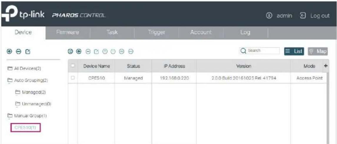
- Then the selected devices will be added to the new group. You can enter the group to check the configuration result.
2.1.2 Monitor the Devices
With Pharos Control, you can monitor the information and status of the devices. What's more, Pharos Control provides real-time graphic data displaying of the devices. The following sections introduce how to view the information and the real-time graphic data of the devices.
View the Device Information
With Pharos Control, you can view the information of each device. Double-click the device and the information will be displayed in the pop-up window. Also, you can view the information directly in the table. Because of the limited space of the page, you may need to drag the slider at the bottom to view all the information options. You can also customize the displayed options by clicking + and enabling your desired options.

The following table introduces all the information options:
Device Name: Displays the name of the device.
For the automatically discovered devices, the device name is the product model. For the manually added devices, the device name is New Device. Only when a device's status is Managed will the device name change to the product model.
Status: Displays the status of the device.
Unmanaged: The device cannot be managed by Pharos Control. It is the initial status of the device. Also, when the managed device is down or disconnected to Pharos Control, the status will change from Managed to Unmanaged.
Managed: The device is being managed by Pharos Control.
Connecting: Pharos Control is trying to connect and manage the device.
Upgrading: The device is being upgraded.
Rebooting: The device is being rebooted.
Connection Failed: Pharos Control is failed to connect the device when trying to manage the device.
Invalid Credentials: Pharos Control is failed to manage the device because of incorrect username, password or port number.
MAC Address: Displays the MAC address of the device.
IP Address: Displays the IP address of the device.
Product: Displays the model and hardware version of the device.
Version Displays the software version of the device.
Mode Displays the working mode of the device, including Access Point, Client, Repeater, Bridge, AP Router and AP Client Router.
SSID Displays the SSID of the device.
Root AP SSID Displays the SSID of the device's root AP when it is in either of the following modes: Client, Repeater, Bridge and AP Client Router.
Client Number Displays the number of the wireless clients connected to the device.
Transmit CCQ Displays the transmission quality of the clients connected to the device. Here CCQ refers to Client Connection Quality.
SNR Displays the Signal-Noise Ratio of the device.
Tx Rate (kbps) Displays the rate of sending data of the device.
Rx Rate (kbps) Displays the rate of receiving data of the device.
Tx Total Displays the total data traffic sent by the device.
Rx Total Displays the total data traffic received by the device.
CPU Load (%) Displays the CPU usage of the device.
CPU Frequency (MHz) Displays the CPU frequency of the device.
Memory Usage (%) Displays the memory usage of the device.
Memory Size (MB) Displays the memory size of the device.
View the Real-time Graphic Data
Pharos Control can collect the real-time data of the managed devices and display it graphically. Follow the steps below to monitor the graphic data information of the device:
1. Select your desired device to be displayed, and click ✅.

2. In the pop-up window, click to create a graphic template.

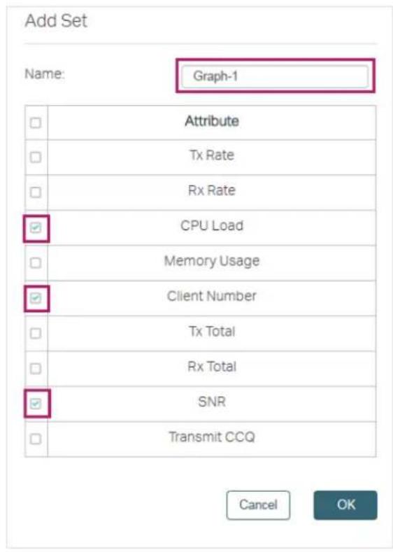
- In the pop-up window, specify a name for the template and select the information options which will be displayed in the graph. For example, we specify the template name as Graph-1, and select CPU Load, Client Number and SNR to be displayed. Click OK.
- The template is created. You can add more templates or delete the unused templates on this page. Also, you can edit the displayed information options in the right-hand column by checking or unchecking the boxes.

- Click the Graph button to enter the following page. Select a template and click ▶ to start the dynamic real-time monitoring. The horizontal axis displays the time, and the vertical axis displays the values. You can click ▶ to stop the dynamic displaying, and move your mouse to any of the curves to view the data information at a specific time. For example, at 16:05:57 of the day, the SNR is -1 dB, the CPU load is 2% and no client is connected to the device for the time being.

2.1.3 Manage the Devices
With Pharos Control, you can centrally manage your Pharos devices. The following sections introduce how to configure, upgrade, reboot and ping the devices, and how to open their management web pages.
Note:
The following operations can be executed only on the devices in Managed status: configuring, upgrading, rebooting and opening the web page.
Configure the Devices
Follow the steps below to configure the devices.
- Select your desired device and click. If you want to upgrade devices in batch, make sure that these devices can be upgraded with the same firmware file.

- In the pop-up window, configure the basic parameters of the device and click OK.

Device Name Displays the name of the device.
Region Displays the region of the device.
| Mode Select the IEEE 802.11 mode the radio uses. The available options vary with the product models.With a frequency band of 2.4GHz, CPE210/CPE220/WBS210 supports five wireless modes: 802.11b, 802.11g, 802.11n, 802.11b/g and 802.11b/g/n. You are recommended to set the 11b/g/n mixed mode, and all of 802.11b, 802.11g and 802.11n wireless stations can connect to the device.CPE510/CPE520/WBS510 has a frequency band of 5GHz, supporting 802.11a, 802.11n and 802.11a/n modes. We suggest to set in 11a/n mode, allowing both 802.11a and 802.11n wireless stations to access the device. | |
| Channel Width | Select the channel width of the device. Options include 5MHz, 10MHz, 20MHz and 20/40MHz. According to IEEE 802.11n standard, using a channel width of 40MHz can increase wireless throughput. However, you may choose lower bandwidth due to the following reasons:Increase the available number of channels within the limited total bandwidth.To avoid interference from overlapping channels occupied by other devices in the environment.Lower bandwidth can concentrate higher transmit power, increasing stability of wireless links over long distances.Subject to the channel width of root AP in Client/ Bridge/ Repeater/ Client Router operation modes. |
| Max Tx Rate Select the maximum data transmission rate. | |
| channel/frequency | Select the channel used by the device to improve wireless performance. This setting is only available in the modes of Access Point and AP Router. We recommend you use the Spectrum Analysis tool to select a proper channel. |
| Transmission Power | Specify the transmit power value. The valid values vary with the prodct models and regions. |
| MAXstream | Enable or disable MAXstream. This feature is only available in the modes of Access Point and AP Router. MAXstream is a proprietary technology of TP-Link for Wi-Fi system. It is based on TDMA (Time Division Multiple Access) so that data streams are transmitted in strict order. MAXstream aims to maximize throughput and minimize latency especially in a multi-STAs circumstance. "Hidden nodes" problem can also be eliminated with MAXstream enabled. We recommend you turn on MAXstream in a large scale wireless deployment to achieve better performance.Note: MAXstream Technology is only compatible with Pharos series products. You cannot connect other Wi-Fi devices to an AP with MAXstream enabled. |
| Distance Settings | Specify the distance between AP and Station. If this device serves as a client, the value is the distance between this device and the root AP. If this device serves as an AP, the value is the distance between the farthest client and this AP.You can manually enter the value or enable the Auto option.Manual: Enter the distance manually in the input box. The value is limited to 0-200km, and we recommend you set the value to 110% of the real distance.Auto: Check the Auto option, then the system will dynamically detect the distance. This function is available only when the distance is less than xx kilometers. The value xx varies according to the channel width you set. CPE210 does not support this option. |
| AP Isolation | Enable or disable AP Isolation. AP Isolation is used to isolate all wireless stations connected to this device so that they cannot communicate with each other. This function will be disabled if WDS/Bridge is enabled. |
Upgrade the Devices
Follow the steps below to upgrade the devices.
- Import the firmware files. For details, refer to Manage Firmware Files.
- Select your desired device and click ⚠️. If you want to upgrade devices in batch, make sure that these devices can be upgraded with the same firmware file.
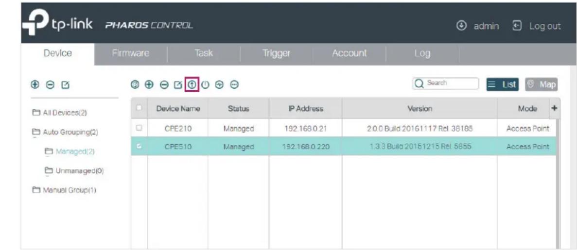
- In the pop-up window, select the appropriate firmware file from the drop-down list, and click OK.

- Then the device status will change to Upgrading. Wait for a while without any operation, and the device will be upgraded automatically.

Reboot the Devices
Follow the steps below to reboot the devices:
- Select one or more devices and click ⏻.

- In the pop-up window, verify the device to be rebooted and click OK. Wait for a moment and the device will reboot automatically.

Ping the Devices
If you want to test the connectivity between Pharos Control and the devices, you can use the Ping feature. Follow the steps below to ping the devices.
- Select your desired device, click the icon, and select Ping in the drop-down menu.

- In the pop-up window, set the number of ping packets to be sent and the timeout value. The timeout value determines how long Pharos Control will wait for the response from the device before the ping is regarded as failed. Click Start to Ping.
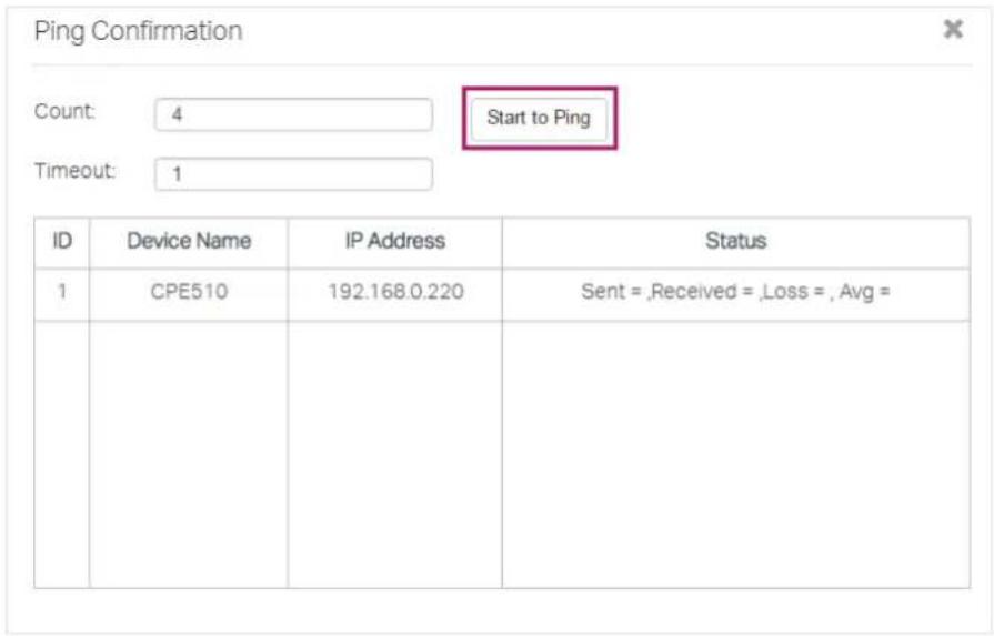
- View the ping result in the Status column. As the following figure shows, Pharos Control sent 4 ping packets to the device and a response was received from the device every time, which indicates that the connection between Pharos Control and the device is normal.

Open the Web UI of the Device
You can open the web UI of each device under management. Select your desired device, click the icon, and select Open Web UI in the drop-down menu. The web UI of the device will then open.

2.1.4 Monitor and Manage the Devices on Google Map
With this feature, you can drag your devices to their actual locations on the Google map, and visually monitor and manage these devices. Go to the Device page and click Map. Then the map page will appear.

All devices are on the map. You can drag these devices to the appropriate locations according to their actual locations. Also, you can select one or more devices on the map, and do the operations introduced in the above sections, such as group the devices, view the graphic data information of the devices, and upgrade, ping, and reboot the devices.
The following table shows all icons and sub-functions on the map.
 | It represents Pharos Control. |
 | It represents the device that is not being managed. |
 | It represents the device that is being managed. |
| Green Line Between Two Devices | It indicates the connection between the two devices is normal. |
| Gray Line Between Two Devices | It indicates the connection between the two devices is failed. |
 | To view the terrain on the map, click Map and check Terrain to enable the terrain display. |
 | Google provides satellite map, and you can click Satellite to change the current map to a satellite map. |
 | Click this button to set whether the information tag will be displayed at the top of the device icon. The tag displays the name and mode of the device. |
 | Click this button to view the map in full screen. |
 | Click this button to zoom in and out the map. |
 | Check this option to lock the devices on the map, which means that the devices cannot be moved with this option enabled. |
2.2 Manage Firmware Files
Firmware is released to upgrade the devices. To centrally and conveniently manage firmware, you can download firmware files from our website and import them to Pharos Control.
Follow the steps below to manage firmware files in Pharos Control:
- Go to the Firmware page, and click the add icon.

- The following window will pop up. Click Browse, choose a firmware file from your local host, and click OK.

- In the same way, import all the firmware files to Pharos Control.
![tp-link PHAROS CONTROL Device Firmware Task Trigger Account\Log Firmware(2) File name Software Version Hardware Version Upload Date Active Uploader CPE210(JUN)_2.0-up-ver2-0-0-P1[20161102-rel39691].bin 2.0.0 2.0 2016/12/29 09:44 true Martin pharos-up-ver2-0-0-P1[20161025-rel41794].bin 2.0.0 2.0 2016…](/content/2026/06/1347218/images/4458cc790250946bb84a6aed433e0dd82f3aadcdb3f2dd33bfc7dd41b4c24ca8.jpg)
You can view the firmware information in the table.
File Name: Displays the name of the firmware file.
Software Version: Displays the software version of the firmware.
Hardware Version: Displays the hardware version of the firmware.
Upload Date: Displays the date and time of uploading the firmware.
Status: Displays the status of the firmware entry. There are two kinds of statuses:
Active: The firmware file can be used to upgrade the devices.
Inactive: The firmware file is forbidden to upgrade the devices.
You can select one or more firmware entries and click ✅ to deactivate the firmware or ⚙ to activate the firmware.
Uploader: Displays the username of whom uploaded the firmware.
- By default, all the firmware files are in the default group named Firmwares. If needed, you can create more groups to classify the firmware files. To add a new group, click + in the left column.
![tp-link PHAROS CONTROL admin Log out Device Firmware Task Trigger Account Log Firmwares(2) File name Software Version Hardware Version Upload Date Active Uploader CPE210(UN)_2.0-up-ver2-0-0-P1[20161102-rel39691].bin 2.0.0 2.0 2016/12/29 09:44 true admin pharos-up-ver2-0-0-P1[20161025-rel41794].bin 2…](/content/2026/06/1347218/images/de56c4d4db55238d5e368a7da70de6eba812c74f9894253fb4bd26e2b47454a5.jpg)
- The following window will pop up. Specify a name for the group and click OK.
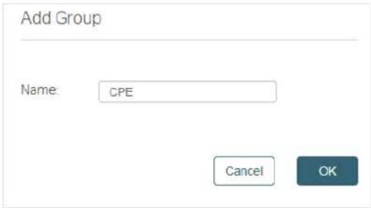
- Select one or more firmware entries, click ⚙️, move your mouse pointer to Add to group, and select the new group.
![tp-link PHAROS CONTROL Device Firmware Task Trigger Account Log Add to group > CPE Software Version Hardware Version Upload Date Active Uploader Remove from group CPE:10(UN)_2.0-up-ver2-0-0-P1[20161102-rel39691]bin 2.0.0 2.0 2016/12/29 09:44 true admin pharos-up-ver2-0-0-P1[20161025-rel41794]bin 2.0…](/content/2026/06/1347218/images/ec06e909bb6d08cdce45b75c0466859da74953bd8320b1007224bdfdd6730f34.jpg)
- Click the group name in the left column, and you can view the group member we just added to this group.
![tp-link PHAROS CONTROL admin Log out Device Firmware Task Trigger Account Log Firmwares(2) CPE(1) File name Software Version Hardware Version Upload Date Active Uploader CPE210(UN)_2.0-up-ver2-0-0-P1[20161102-rei39891].bin 2.0.0 2.0 2018/12/29 09:44 false admin Search](/content/2026/06/1347218/images/457e95ed9972ac197bb747a5cc879865991c3392472ca67e9c179bbc9ef740f0.jpg)
If you want to remove a firmware entry from a group, you can select the firmware, click and click Remove from the group. Also, you can delete or edit the group as the following table shows.

2.3 Configure Scheduled Tasks
With this feature, you can set scheduled tasks for the devices and Pharos Control. For example, you can configure the managed devices to reboot every two weeks, or configure Pharos Control to discover the devices in the LAN at 8:00 am every day, which facilitates you manage your network.
Follow the steps below to configure scheduled rules.
1. Go to the Task page. Click


2. Then the following window will pop up.
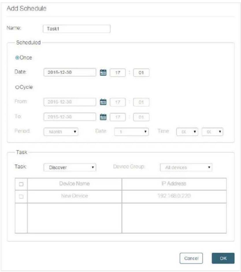
1) Specify a name for the task. 2) Configure the Scheduled parameters:

The following table introduces the configuration options.
Once Enable this option and specify a point in time. The task will be performed at the specified time.
For example, the following configuration indicates that the task will be performed at 8pm on Feb 22nd, 2017. And the task will be performed only once.
Once
Date:
2017-02-22

20
:
00
Cycle Enable this option and specify a time range and the task interval. During the time range, the task will be performed at every interval.
For example, the following configuration indicates that from Feb 20th, 2017 to Apr 20th, 2017, the task will be performed at 8 am each Sunday morning.
Cycle
From:
2017-02-20

10
56
To:
2017-04-20

10
56
Period:
Week
Date:
Sun
Time:
08
▼ :
00
3) Select a task type and configure the corresponding options.

The following table introduces the task types:
Discover: Pharos Control will discover the devices in the network at the scheduled time.
Reboot: Pharos Control will reboot the selected devices at the scheduled time.
Firmware Upgrade: Pharos Control will upgrade the selected devices using the specified firmware at the scheduled time.
Manage: Pharos Control will check whether the selected devices are currently being managed at the scheduled time. If not, Pharos Control will try to change the status of the devices from Unmanaged to Managed.
3. Click OK.
2.4 Configure Trigger Rules
This feature is used to inform you of a device status change via email and help you manage the devices automatically. For example, if a device with Managed status has an issue and changes to Unmanaged status, Pharos Control will try to manage this device again, and at the same time, send an email to the specific mailbox to inform you of this event.
Follow the steps below to configure the Trigger feature:
1. Go to the Trigger page and click ✅.

- The following window will pop up. Configure the required options.

Name: Specify a name for this trigger rule.
Device Group: Select a device group on which the rule will take effect.
Condition: Configure the trigger conditions. For example, if we choose From as Managed and To as Unmanaged, Pharos Control will send an email to the specific mailbox when the status of a device in the selected group changes from Managed to Unmanaged.
Type: If the condition From is selected as Managed, there are two types: Email Notification and Manage Device. If the condition From is selected as Unmanaged/Error, there is only one type: Email Notification.
Email Notification: Pharos Control will send an email to the specific mailbox.
Manage Device: Pharos Control will try to change the status of the device from Unmanaged/Error to Managed.
Action Settings: Set the email information.
To: Set the recipient's mailbox address.
Subject: Set a subject for the email.
- Click the Email Settings tag to expand the following section. Fill in the mail server information according to your own details.

■ If you do not use a Gmail server to send the trigger email, select Default option, configure the following parameters, and click OK.
| Email Server Address Enter the IP address of the email server. |
| Email Server Port Enter the port of the email server. |
| SSL Enable or disable SSL encryption. If your email server supports SSL encryption, we recommend that you enable this option to enhance the email security. |
| Email Account Enter the email account. |
| Email Password Enter the email password. |
■ If you use a Gmail server to send the trigger email, there are two configuration methods.
Method 1:
1) Complete the configurations as shown above. 2) Turn on "Allow less secure apps" option in your Gmail account settings. You can click the note with blue color on the page to quickly access the Gmail website.
Method 2:
1) Select Gmail (OAuth2) option.

2) Click Get Code, and you will be directed to the Gmail website. 3) Log in to your Gmail account and copy the received code to the Code area on the above page. 4) Click Validate to check whether the code is valid. If an error is displayed, check whether the code is correctly copied and try again. If a green tick is displayed, just click OK to save your settings, and Pharos Control will use your Gmail account to send the trigger emails.
- To verify whether the email settings are correctly configured, select the rule you just created, and click ▶ to do a test. Pharos Control will send an email to the recipient's mailbox via the email server. You can check whether an email is received in the recipient's mailbox. If it is, the Trigger feature works normally.

- After all the configurations above are completed, you can use this feature without any other operations. If needed, you can also manage the trigger rules and view the trigger events on this page.
■ Manage Trigger Rules

Select one or more trigger rules and do the corresponding operations for this rule.
| Click this button to edit the rule. | |
| Click this button to delete the rule. | |
| Click this button to activate the rule, and the status of this rule will change from Inactive to Active. | |
| Click this button to deactivate the rule, and the status of this rule will change from Active to Inactive. | |
| Click this button to make Pharos Control send a test email to the recipient's mailbox. |
■ View Trigger Events
Once an event matching any of the rules occurs, an email will be sent and a corresponding trigger event will be recorded in the event list. Click Trigger Events in the left column to view the trigger events.
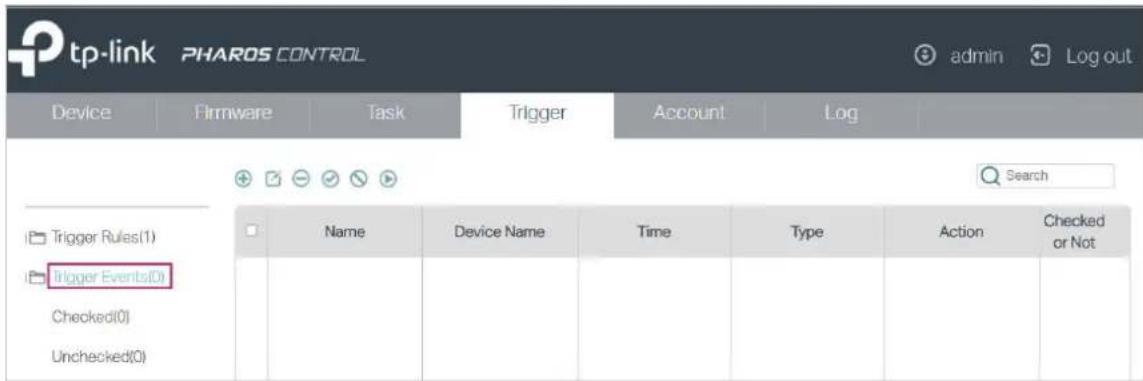
Name: Displays the name of the trigger rule.
Device Name: Displays the name of the device.
Time: Displays the time when the event happened.
Type: Displays the type of event.
Action: Displays the trigger rule type: Manage Device or Email Notification.
Checked or Not Displays whether the event has been checked or not.
3 Manage Accounts and Logs
This chapter introduces how to manage Pharos Control accounts and logs:
■ Manage Accounts ■ Manage Logs
3.1 Manage Accounts
Pharos Control supports three account types: Administrator, Manager, and Guest. The account created during the installation process is an Administrator account and cannot be deleted. If your current account type is Administrator, you can follow the steps below to create another account.
1. Go to the Account page and click ✅.

2. Then the following window will pop up. Configure the required parameters and click OK.

Role: Select the type of account to be created. The following options are provided: Administrator, Manager, and Guest.
Administrator can view and configure the devices, and can change the configurations of Pharos Control.
Manager can view and configure the devices, but cannot change the configurations of Pharos Control.
Guest can only view the devices.
User Name: Specify a username.
Password: Specify a password.
Confirm Password: Enter the password again for confirmation.
Email Specify the email for the user.
Telephone (Optional) Specify the telephone number of the user.
Note (Optional) Specify a note.
Also, you can select an account and click to edit it.
3.2 Manage Logs
The logs of Pharos Control can effectively record, classify and manage the system information of the managed devices, providing powerful support for you to monitor network operations and diagnose malfunctions.
Go to the Log page, and you can view all the logs. Also, you can click the tags in the left column to view the classified logs, including normal logs, events and errors.

Pharos Control provides two operations for the logs: exporting the logs to your local host and deleting the logs.
■ Export the Logs
You can export the logs which are recorded in a specific period of time. But exporting a single log is not supported.
Follow the steps below to export the logs:
- Click 🔒 and the following window will pop up. Specify a time range and click OK.

- The logs will be exported in the excel file. Select a file path to save the logs in your local host.
| 1 | Time | Message | Type | Device Name | MAC Address |
| 2 | 2016/12/29 02:58 | Trigger has been added successfully, whose name is Rule 1 | LOG | ||
| 3 | 2016/12/29 02:58 | Server Trigger Manager updated. Add new rule, which name is Rule 1 | LOG | ||
| 4 | 2016/12/29 02:58 | Mail server setting has been changed. mail server address is 127.0.0.1 | LOG | ||
| 5 | 2016/12/29 01:44 | User: admin login | LOG | ||
| 6 | 2016/12/29 11:28 | Delete rule successfully, which rule name is 1 | LOG | ||
| 7 | 2016/12/29 11:28 | Server Trigger Manager updated. Delete rule, which name is 1 | LOG | ||
| 8 | 2016/12/29 11:15 | FirmwareInfotree has been updated. | LOG | ||
| 9 | 2016/12/29 11:15 | Group has been edited successfully, whose name is CPE | LOG | ||
| 10 | 2016/12/29 11:15 | FirmwareInfotree has been updated. | LOG | ||
| 11 | 2016/12/29 11:15 | Group has been edited successfully, whose name is CPE | LOG | ||
| 12 | 2016/12/29 10:54 | 1 firmware(s) have been deactivated successfully | LOG | ||
| 13 | 2016/12/29 10:54 | Deactive firmware info , which id is 3, name is CPE210(UN), 2.0-up-ver2-0-0-P1[20161102-rs03691] bin | LOG | ||
| 14 | 2016/12/29 10:15 | FirmwareInfoTreefree update failed. Database error | ERROR | ||
| 15 | 2016/12/29 10:05 | FirmwareInfotree has been updated. | LOG | ||
| 16 | 2016/12/29 10:05 | Group has been edited successfully, whose name is CPE | LOG | ||
| 17 | 2016/12/29 09:54 | FirmwareInfotree has been updated. | LOG | ||
| 18 | 2016/12/29 09:54 | Group has been added successfully, whose name is CPE | LOG | ||
| 19 | 2016/12/29 09:36 | 2 firmware(s) have been deleted successfully. | LOG | ||
| 20 | 2016/12/29 09:36 | Delete firmware , which id is 2, name is pharms-up-ver2-0-0-P1[20161025-rs41794] bin | LOG | ||
| 21 | 2016/12/29 09:36 | Delete firmware , which id is 1, name is CPE210(UN), 2.8-up-ver2-0-0-P1[20161102-rs9999] bin | LOG | ||
| 22 | 2016/12/29 09:25 | User: admin login | LOG | ||
| 23 | 2016/12/28 09:28 | Edit device completed, which device id is 6, device name is New Device | EVENT | ||
| 24 | 2016/12/28 07:21 | Device has been added successfully. device id is 6, device name is New Device | EVENT | ||
| 25 | 2016/12/28 07:18 | 1 device(s) have been deleted successfully. | LOG | ||
| 26 | 2016/12/28 07:18 | Delete device, which id is 3 device name is CPE510 | LOG | CPE510 | 3B-BS-CZ-BD-20-SC |
| 27 | 2016/12/28 07:32 | Edit device completed, which device id is 3, device name is CPE510 | EVENT | CPE510 | 3B-BS-CZ-BD-20-SC |
| 28 | 2016/12/28 07:31 | 2 device(s) have been deleted successfully. | LOG | ||
| 29 | 2016/12/28 07:31 | Delete device, which id is 5 device name is New Device. | LOG | ||
| 30 | 2016/12/28 07:31 | Delete device, which id is 4 device name is New Device. | LOG | ||
| 31 | 2016/12/28 11:57 | Discovery task is completed, whose name is Scheduled - Discovery [2016-12-28 11:56:36] . . . . . . . . . . . . . . . . . . . . . . . . . . . . . . . . . . . . . . . . . . . . . . . . . . . . . . . . . . . . . . . . . . . . . . . . . . . . . . . . . . . . . . . . . . . . . . . . . . . . | |||
| 32 | 2016/12/28 11:56 | Discovery task started, which name is Scheduled - Discovery [2016-12-28 11:56:36] .. | |||
| 33 | 2016/12/28 11:47 | Discovery task has been cancelled, whose name is DISCOVERY [2016-12-28 11:57:36] | |||
■ Delete the Logs
There are two ways to delete the logs: delete the selected logs and delete the logs recorded in a period of time. Also, you can delete all logs in the table with one click.
Follow the steps below to delete the selected logs:
- Select one or more logs you want to delete and click ☑.

- The following window will pop up. Select Delete the selected logs and click OK.

Follow the steps below to delete the logs recorded in a period of time or delete all logs in the table.
- Click ⊖ directly.

- The following window will pop up. To delete the logs in a period of time, select Delete the logs in a time interval, and specify a time range. To delete all logs, select Delete all logs. And then click OK.


- INTENDED READERS
- CONVENTIONS
- MORE INFO
- CONTENTS
- QUICK START
- MONITOR AND MANAGE THE NETWORK
- MANAGE ACCOUNTS AND LOGS
- DETERMINE THE NETWORK TOPOLOGY
- MANAGE DEVICES IN THE SAME NETWORK SEGMENT
- TIPS
- NOTE
- MANAGE DEVICES IN DIFFERENT NETWORK SEGMENT
- INSTALL PHAROS CONTROL
- SYSTEM REQUIREMENTS
- INSTALL PHAROS CONTROL SOFTWARE
- INSTALLATION ON WINDOWS SYSTEM
- CLICK NEXT
- INSTALLATION ON LINUX SYSTEM
- LOG IN TO PHAROS CONTROL
- LAUNCH PHAROS CONTROL SERVER
- LAUNCH ON WINDOWS SYSTEM
- LAUNCH ON LINUX SYSTEM
- LOG IN TO THE MANAGEMENT INTERFACE
- ADD THE DEVICES TO BE MANAGED
- DISCOVER THE DEVICES AUTOMATICALLY
- GO TO THE DEVICE PAGE, AND CLICK 🔒
- ADD THE DEVICES MANUALLY
- SELECT THE DEVICE AND CLICK
- THEN THE FOLLOWING WINDOW WILL POP UP. CLICK START MANAGING
- MONITOR AND MANAGE THE DEVICES
- GROUP THE DEVICES
- AUTO GROUPING
- MANUAL GROUPING
- MONITOR THE DEVICES
- VIEW THE DEVICE INFORMATION
- VIEW THE REAL-TIME GRAPHIC DATA
- SELECT YOUR DESIRED DEVICE TO BE DISPLAYED, AND CLICK ✅
- IN THE POP-UP WINDOW, CLICK TO CREATE A GRAPHIC TEMPLATE
- MANAGE THE DEVICES
- CONFIGURE THE DEVICES
- UPGRADE THE DEVICES
- REBOOT THE DEVICES
- PING THE DEVICES
- OPEN THE WEB UI OF THE DEVICE
- MONITOR AND MANAGE THE DEVICES ON GOOGLE MAP
- MANAGE FIRMWARE FILES
- CONFIGURE SCHEDULED TASKS
- GO TO THE TASK PAGE. CLICK
- THEN THE FOLLOWING WINDOW WILL POP UP
- CLICK OK
- CONFIGURE TRIGGER RULES
- GO TO THE TRIGGER PAGE AND CLICK ✅
- MANAGE TRIGGER RULES
- VIEW TRIGGER EVENTS
- MANAGE ACCOUNTS
- GO TO THE ACCOUNT PAGE AND CLICK ✅
- THEN THE FOLLOWING WINDOW WILL POP UP. CONFIGURE THE REQUIRED PARAMETERS AND CLICK OK
- MANAGE LOGS
- EXPORT THE LOGS
- DELETE THE LOGS
Brand : TP-LINK
Model : CPE710
Category : Access Point