
R12000 - Uninterruptible power supply HP - Free user manual and instructions
Find the device manual for free R12000 HP in PDF.


| Product Type | Uninterruptible Power Supply (UPS) |
| Model | HP R12000 |
| Form Factor | Rackmount / Tower |
| Dimensions (HxWxD) | 3U (5.2 x 17.5 x 20.5 in) |
| Weight | 65.5 lbs (29.7 kg) |
| Power Rating | 12000 VA / 10800 W |
| Input Voltage | 200-240 VAC, 50/60 Hz |
| Output Voltage | 200/208/220/230/240 VAC |
| Battery Type | Valve-Regulated Lead-Acid (VRLA) |
| Typical Backup Time | 10 min at full load, 25 min at half load |
| Charging Time | 3-5 hours to 90% capacity |
| Output Connections | (8) NEMA 5-20R + (2) L6-30R + Hardwiring terminal |
| Communication Ports | USB, RS-232, Ethernet (SNMP), dry contacts |
| Management Software | HP Power Manager, compatible with HP servers |
| Protection Features | Surge protection, EMI/RFI filtering, automatic voltage regulation (AVR) |
| Monitoring | LCD display for load level, battery status, alerts |
| Safety Certifications | UL, CUL, FCC Class A, ENERGY STAR |
| Operating Temperature | 32°F to 104°F (0°C to 40°C) |
| Humidity Range | 0-95% non-condensing |
| Maintenance | User-replaceable batteries, hot-swappable |
| Spare Parts Available | Battery packs, fan modules, control boards |
| Warranty | 3 years (parts & labor), extended options available |
Frequently Asked Questions - R12000 HP
User questions about R12000 HP
0 question about this device. Answer the ones you know or ask your own.
Ask a new question about this device
Download the instructions for your Uninterruptible power supply in PDF format for free! Find your manual R12000 - HP and take your electronic device back in hand. On this page are published all the documents necessary for the use of your device. R12000 by HP.
USER MANUAL R12000 HP
HP R12000 and R18000 DirectFlow UPS User Guide
Abstract
This document includes installation, configuration, and operation information for the HP R12000 and R18000 DirectFlow UPS. This document is for the person who installs and maintains power products. HP assumes you are qualified in the servicing of high-voltage equipment and trained in recognizing hazards in products with hazardous energy levels.

Part Number: 709321-003
April 2015
Edition: 3
© Copyright 2014, 2015 Hewlett-Packard Development Company, L.P.
The information contained herein is subject to change without notice. The only warranties for HP products and services are set forth in the express warranty statements accompanying such products and services. Nothing herein should be construed as constituting an additional warranty. HP shall not be liable for technical or editorial errors or omissions contained herein.
Links to third-party websites take you outside the HP website. HP has no control over and is not responsible for information outside HP.com.
Confidential computer software. Valid license from HP required for possession, use or copying. Consistent with FAR 12.211 and 12.212, Commercial Computer Software, Computer Software Documentation, and Technical Data for Commercial Items are licensed to the U.S. Government under vendor's standard commercial license.
Microsoft®, Windows®, and Windows Server® are trademarks of the Microsoft group of companies.
Contents
Overview 6
HP DirectFlow UPS overview 6
Power management options....6
Advanced monitoring and management features 7
Location Discovery Services for the UPS configuration 7
REPO port 8
Component identification 8
HP R12000 DirectFlow UPS 8
HP R18000 DirectFlow UPS 11
1U battery pack rear panel.... 14
3U battery pack rear panel....15
Power unit and battery pack configurations 15
Installation 18
Precautions....18
Important device safety information.... 18
Preparing to install the hardware....19
Tools and materials....19
Selecting a site....19
Readying the equipment 20
Installing rack rails 20
Installing rack rails for the 1U power unit....20
Installing rack rails for the 2U power unit....23
Installing rack rails for the 1U battery pack 26
Installing rack rails for the 3U battery pack 29
Installing battery packs....33
Powering down the UPS 33
Installing the 1U battery pack....33
Installing the 3U battery pack....39
Installing the power unit 47
Installing the R12000DF power unit 47
Installing the R18000DF power unit 52
Connecting the UPS to utility power 56
Connecting devices 57
Starting power to the load 57
Continuing the installation of components 57
Installing the Management Module card....57
Installing the Management Module card in the 1U power unit 58
Installing the Management Module card in the 2U power unit....60
Checking the Health/Alert LED 62
Configuration 63
Accessing the Management Module 63
Launching a terminal emulation program....63
Launching a telnet session....64
Navigating the Service Menu....64
Service Menu....65
Module Configuration submenu....65
Configuring the Management Module card for remote access....70
Launching a web browser....71
Signing into the Management Module web interface....71
Configuring the power unit 72
UPS operations....73
Navigating UPS menu options 73
UPS menu options....73
Configuring the battery charge power levels 75
Changing the language....76
Working with UPS modes of operation....76
AC mode 76
Battery mode 77
Bypass mode 77
Maintenance 78
Updating the UPS firmware 78
Restoring power after a REPO activation 79
Verifying the REPO port connection 79
Powering down the UPS and battery packs 80
Replacing the batteries....80
Important battery safety information 80
Battery care and storage guidelines 80
Battery replacement procedure 81
Replacing the 1U battery pack....83
Replacing the 3U battery pack 84
Replacing the Management Module card 85
Replacing the power module 85
Replacing the 1U power unit....86
Replacing the 2U power unit....87
Troubleshooting 89
LED and audible alarm troubleshooting 89
Alarm descriptions and SNMP trap codes....90
General alarm condition 92
UPS does not start 93
Wiring condition....93
Utility power condition 93
Battery connection condition....93
REPO condition....94
UPS is in Bypass mode....94
Overload condition 94
UPS is in Battery mode....95
UPS frequently switches between utility and battery power....95
Battery fault 95
UPS backup time is short 95
Low battery shutdown 95
Deep Sleep mode....95
UPS alarm code decision flowcharts 97
Specifications 112
Environmental specifications 112
Power unit physical specifications....112
REPO port specifications....112
Battery pack physical specifications....112
1U battery pack specifications 113
3U battery pack specifications 113
Lead acid battery module specifications 113
Lithium-ion battery module specifications.... 113
Battery runtime 114
UPS input specifications 114
UPS output specifications.... 115
Voltage specifications 115
Output tolerance specifications.... 115
Output feature specifications....115
Spares....116
R12000DF UPS spare parts list 116
R18000DF UPS spare parts list 116
Hardware options 117
Electrostatic discharge 118
Preventing electrostatic discharge 118
Grounding methods to prevent electrostatic discharge 118
Regulatory information 119
Safety and regulatory compliance 119
Turkey RoHS material content declaration 119
Ukraine RoHS material content declaration 119
Warranty information 119
Support and other resources 120
Before you contact HP 120
HP contact information 120
HP product QuickSpecs....120
Documentation feedback 121
Acronyms and abbreviations.... 122
Index 124
Overview
HP DirectFlow UPS overview
The HP DirectFlow UPS features a configurable rack-mount design that offers three-phase power protection for loads up to a maximum of 20000 VA/18000 W (these numbers might vary by model). Features include:
- Configurations for extending runtime
- A configurable power unit with the following rack unit heights:
R12000DF—1U
R18000DF-2U
- Optional 3U lead acid or 1U lithium-ion battery packs. A minimum of 60 seconds of backup power with one battery pack and 5 minutes of backup power with two battery packs provided for the maximum load.
• Advanced battery management to increase battery service life and optimize recharge time
- Warning before the end of the useful battery life
- Easily replaceable battery modules that simplify maintenance
- Configurable utility and generator battery charge power level switching.
- Optional HP DirectFlow UPS Management Module network connectivity with advanced remote monitoring, control, and management features. Built-in location awareness of components. Emergency shutdown control through a REPO port.
- Firmware that is service upgradeable through a standard DB-9 serial communication port. Backed by worldwide agency approvals.
To benefit from product enhancements, update to the latest versions of UPS firmware and software. To download the UPS firmware and software, see the HP website (http://www.hp.com/go/rackandpower).
Power management options
The DirectFlow UPS is comprised of an HP DirectFlow Power Unit configured with either HP DirectFlow VRLA Battery Packs (3U) or an R12000DF (1U) or R18000DF (3U) HP DirectFlow Lithium-ion Battery Pack.
The DirectFlow UPS works within an overall power management plan that can include utility, generator, and battery power.
The power unit includes front panel controls and an LCD screen for navigating UPS menu options (on page 73) to access system values. Certain values can be configured to accommodate your power management plan.
Each battery pack provides a minimum of 60 seconds of backup power as a stopgap for a power supply lag or outage. Depending upon configuration, including the number of battery packs and load requirements, the
UPS can extend backup power for an increased amount of time. Distribute the load as evenly as possible across the UPS configuration to most efficiently use the powerful three-phase UPS design.
The UPS modes of operation allow the UPS to transfer seamlessly between AC, Battery, and Bypass modes to supply power to connected devices without interruption. For more information, see "Working with UPS modes of operation (on page 76)." The power unit can use a built-in, time-based algorithm to switch between utility and generator battery charging power levels when transferring operating modes. Using a lower charge level while the UPS runs on generator power maximizes the output available to connected devices. The Management Module provides additional features to receive generator commands. To set UPS battery charge power levels, see "Configuring the battery charge power levels (on page 75)."
Advanced monitoring and management features
The Management Module card reports detailed information to the Management Module web interface where the information is graphically displayed. Many commands and functions can be customized from the interface. Customizable setup options in the UPS Service Menu can also be accessed using the Management Module card. The Management Module is designed specifically for the DirectFlow UPS. It is not intended for installation in other UPS devices.
To install and initially configure the Management Module in the DirectFlow UPS, see "Installing the Management Module card (on page 57)" and "Accessing the Management Module (on page 63)." For details about using the Management Module card and web interface, see the HP DirectFlow UPS Management Module User Guide on the HP website (http://www.hp.com/support/DFUPS_MM_UG_en).
Location Discovery Services for the UPS configuration
HP provides built-in location awareness of rack components, a capability that works hand-in-hand with technology in the new HP Intelligent Series racks. Together, the technologies provide the rack identification number and precise U location of the components. This information is communicated through power management software.
HP R12000DF
HP R18000DF
When the power unit is fully seated within the rack, Discovery Services connectors meet with a rack-mounted EEPROM strip. Discovery Services reports the specific location of the power unit and a calculated location of any battery packs. The battery packs must be installed directly beneath the power unit in the rack, without a U gap, for Discovery Services to locate them. Racks without pre-installed EEPROM strips may be upgraded by ordering and installing the strips, available on the HP website
(http://www.hp.com/products/rackoptions).
REPO port
The power unit includes an isolated REPO port. When properly wired, the REPO feature enables the power at the UPS output receptacles to be switched off from a remote location. To use this feature, the REPO port must be connected to a remote, normally open switch (not supplied). The REPO switch is used in conjunction with a main disconnect device that removes the AC source from the input of the power unit.
When the switch is closed:
- The REPO feature immediately powers down protected devices and does not utilize an orderly shutdown procedure. • The REPO feature shuts down power units operating under utility, generator, or battery power.
To connect a REPO port, see either "Connecting the R12000DF REPO port (on page 49)" or "Connecting the R18000DF REPO port (on page 54)." To restore power to the load devices after the REPO feature has been activated, see "Restoring power after a REPO activation (on page 79)."
Component identification
HP R12000 DirectFlow UPS
The components in the following sections are found in the HP R12000 DirectFlow UPS.
Power unit front panel controls

| Item | Component Description | |
| 1 | UPS fault LED | Red light indicates a fault; no light indicates proper function. |
| 2 | Bypass mode LED Green | light indicates Bypass mode; no light indicates AC mode. |
| 3 | Battery mode LED Yellow | light indicates Battery mode; flashing indicates low battery. |
| 4 | Input LED | Green light indicates that the power input is adequate. |
| 5 | Up arrow | Press to scroll up through the menu structure. |
| 6 | Down arrow | Press to scroll down through the menu structure. |
| 7 | Off/ESC/Clear fault button | In AC mode, press the button for 3 seconds to transfer the UPS to Bypass mode; in Battery mode, press for 3 seconds to shut down the UPS output.During menu selection, press the button to go back to the previous menu.During a UPS fault, press the button for 3 seconds to clear the fault and transfer the UPS to Bypass mode. |
| 8 | On/Enter button | Press the button for 3 seconds to turn the UPS on; press the button to confirm setup or menu entries. |
Power unit rear panel

| Item Description | |
| 1 | Cover plate for option slot |
| 2 | REPO port |
| 3 | DB-9 serial port for flashing UPS firmware |
| 4 | DB-15 port for a CAN Bus cable for battery pack communication |
| 5 | Power cable for connection to the battery pack |
| 6 | Input/output power module connection |
| 7 | Input/output power module connection |
Power unit rear panel with components

| Item Description | |
| 1 | HP DirectFlow UPS Management Module card |
| 2 | HP DirectFlow Input/Output Power Module switch |
| 3 | HP DirectFlow Input/Output Power Module connection and cables |
Power unit rear panel with Management Module card

| Item Description | |
| 1 | RJ-45 for network or Ethernet communications |
| 2 | DB-9 serial port for configuration and flashing card firmware |
| 3 | Power LED |
| 4 | Health/Alert LED |
HP R18000 DirectFlow UPS
The components in the following sections are found in the HP R18000 DirectFlow UPS.
Power unit front panel controls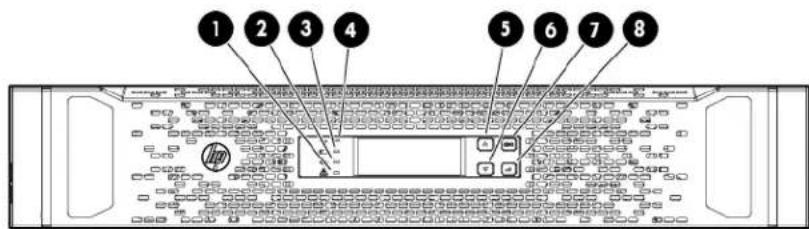
| Item | Component Description | |
| 1 | UPS fault LED Red light | indicates a fault; no light indicates proper function. |
| 2 | Bypass mode LED Green light | indicates Bypass mode; no light indicates AC mode. |
| 3 | Battery mode LED Yellow light | indicates Battery mode; flashing indicates low battery. |
| 4 | Input LED Green light | indicates that the power input is adequate. |
| 5 | Up arrow | Press to scroll up through the menu structure. |
| 6 | Down arrow | Press to scroll down through the menu structure. |
| 7 | Off/ESC/Clear fault button | In AC mode, press the button for 3 seconds to transfer the UPS to Bypass mode; in Battery mode, press for 3 seconds to power down the UPS output.During menu selection, press the button to go back to the previous menu.During a UPS fault, press the button for 3 seconds to clear the fault and transfer the UPS to Bypass mode. |
| 8 | On/Enter button | Press the button for 3 seconds to power up the UPS on; press the button to confirm setup or menu entries. |
Power unit rear panel

| Item Description | |
| 1 | Cover plate for option slot |
| 2 | REPO port |
| 3 | DB-9 serial port for flashing UPS firmware |
| 4 | DB-15 port for a CAN Bus cable for battery pack communication |
| 5 | Power cable for connection to the battery pack |
| 6 | Input/output power module connection |
| 7 | Input/output power module connection |
Power unit rear panel with components

| Item Description | |
| 1 | HP DirectFlow UPS Management Module card |
| 2 | HP DirectFlow Input/Output Power Module switch |
| 3 | HP DirectFlow Input/Output Power Module connection and cables |
Power unit rear panel with Management Module card
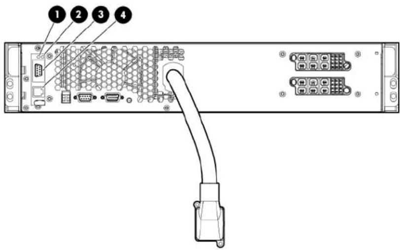
| Item Description | |
| 1 | Power LED |
| 2 | Health/Alert LED |
| 3 | DB-9 serial port for configuration and flashing card firmware |
| 4 | RJ-45 for network or Ethernet communications |
1U battery pack rear panel

| Item Description | |
| 1 | Connection for a DC to DC power cable to the power unit |
| 2 | Circuit breaker switch |
| 3 | Connection for a DC to DC power cable to the battery pack |
| 4 | DB-15 ports for CAN Bus cables for battery pack communication |
3U battery pack rear panel

| Item Description | |
| 1 | Connection for a DC to DC power cable to the power unit |
| 2 | Connection for a DC to DC power cable to the battery pack |
| 3 | DB-15 ports for CAN Bus cables for battery pack communication |
| 4 | Circuit breaker switch |
Power unit and battery pack configurations
The DirectFlow UPS can be configured in the following ways:
- DirectFlow power unit without any battery packs
The power unit can work as a standalone line conditioner, or active filter, that mitigates harmonics and power factor for the input AC line that supplies utility or generator power. To set the power unit active current correction (ACC) options, see the "UPS menu options (on page 73)."
A configuration without battery packs does not supply power for extended runtime.
- DirectFlow power unit with one battery pack
- 3U DirectFlow Battery Pack

- 1U DirectFlow Battery Pack

- DirectFlow power unit with two battery packs in series
The battery packs must be the same rack unit height and battery type; for instance, the power unit could connect to a 3U lead acid battery pack connected in series to a 3U lead acid battery pack.
- Two 3U DirectFlow Battery Packs

- Two 1U DirectFlow Battery Packs

Installation
Precautions
See the complete regulatory compliance notices in Safety and Compliance Information for Server, Storage, Power, Networking, and Rack Products on the HP website (http://www.hp.com/support/Safety-Compliance-EnterpriseProducts). In addition, follow the safety precautions that are specific to this device.
Save these instructions. This document contains important safety instructions that should be followed during installation, operation, and maintenance of the UPS and batteries.

This symbol indicates that the power unit exceeds the recommended weight for one individual to handle safely. Weight for each power unit is:
• R12000DF—16 kg (35.2 lb) • R18000DF—20.87 kg (46 lb)
WARNING: To reduce the risk of personal injury or damage to the equipment, observe local occupational health and safety requirements and guidelines for manual material handling.
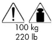
This symbol indicates that the 3U DirectFlow Battery Pack exceeds the recommended weight for one individual to handle safely.
WARNING: To reduce the risk of personal injury or damage to the equipment, observe local occupational health and safety requirements and guidelines for manual material handling.

This symbol indicates that the 1U DirectFlow Battery Pack exceeds the recommended weight for one individual to handle safely.
WARNING: To reduce the risk of personal injury or damage to the equipment, observe local occupational health and safety requirements and guidelines for manual material handling.

WARNING: A risk of personal injury or damage to the equipment exists. Uneven loading of equipment in the rack might cause the rack to become unstable. Install the heavier components first, and then continue to populate the rack from the bottom to the top.

WARNING: A risk of personal injury from electric shock and hazardous energy levels exists. The installation of options and routine maintenance and service of this product must be performed by individuals who are knowledgeable about the procedures, precautions, and hazards associated with AC power products.

WARNING: Contact with any part of a grounded battery can result in electrical shock. Shock risk is reduced if grounds are removed during installation and maintenance.
Important device safety information

WARNING: To reduce the risk of fire, only connect unit input to a circuit provided with branch circuit overcurrent protection for 30 A rating in accordance with the National Electric Code, ANSI/NFPA 70. Disconnect the charging source prior to connecting or disconnecting battery terminals. Determine if the battery is inadvertently grounded. If inadvertently grounded, remove the source from the ground.

CAUTION: The DirectFlow UPS is intended to supply three-phase linear/PFC loads only.

IMPORTANT: The rating label on the device provides the class (A or B) of the equipment. Class B devices have a Federal Communications Commission (FCC) logo or FCC ID on the label. Class A devices do not have an FCC logo or FCC ID on the label. After determining the class of the device, see the complete regulatory compliance notices in Safety and Compliance Information for Server, Storage, Power, Networking, and Rack Products on the HP website (http://www.hp.com/support/Safety-Compliance-EnterpriseProducts).
Preparing to install the hardware
To prepare for the hardware installation:
- Ensure the necessary tools and materials (on page 19) are available.
- Select a site.
- Ready the equipment for installation in the rack.
Tools and materials
The following tools are required for installation:
• Phillips screwdriver • 10-mm hex-nut driver
The following items are supplied with the rack:
- Cage nut-fitting tool
To download the latest software version, see the HP website (http://www.hp.com/go/rackandpower).
Additional materials might be supplied depending upon the optional devices included. For a specific list of materials, see the install card for each device.
Selecting a site

WARNING: To prevent fire or electric shock, install the unit in a temperature- and humidity-controlled indoor environment, free of conductive contaminants.
When selecting a site, consider the following factors:
- Elevated operating ambient temperature—If the equipment is installed in a closed or multi-unit rack assembly, the operating ambient temperature of the rack environment might be greater than room ambient temperature. Install the equipment in an environment compatible with the operating temperature.
- Reduced air flow—In the rack, the rate of air flow required for safe operation of the equipment must not be compromised.
- Circuit overloading—Consideration should be given to the connection of the equipment to the supply circuit and the effect that overloading of the circuits might have on overcurrent protection and supply wiring. Appropriate consideration of equipment nameplate ratings should be used when addressing this concern.
- Reliable earthing—Reliable earthing of rack-mounted equipment should be maintained. Particular attention should be given to supply connections other than direct connections to the branch circuit, such as the use of power strips.
- Electrical requirements—All models require a dedicated (unshared) branch circuit, including an unshared grounding conductor, that is suitably rated for the specific UPS as stated in "UPS input specifications (on page 114)."
Readying the equipment
- Check the battery recharge date specified on the label that is affixed to the shipping carton.

IMPORTANT: Do not use the battery if the recharge date has passed. If the date on the battery recharge date label has passed without the battery being recharged, contact an HP authorized service representative for directions.
- Transport the packaged unit to its installation location.
- Unpack the equipment near the rack where the unit will be assembled.

CAUTION: Always plan the rack installation so that the heaviest item is on the bottom of the rack. Install the heaviest item first, and continue to populate the rack from the bottom to the top.
Installing rack rails

IMPORTANT: For rack shipping or relocation of any of the components, ensure hex nuts and shipping brackets are used with the rail supports. See the optional shipping steps in the rack rail and component installation sections.
Reinforcement plates are required for rails that support the 2U power unit and 3U battery packs. Plates are not needed for those rails that support the 1U power unit or 1U battery packs.
Installing rack rails for the 1U power unit
WARNING: To reduce the risk of personal injury or damage to the equipment, be sure that:
• The leveling feet are extended to the floor. • The full weight of the rack rests on the leveling feet. • The stabilizing feet are attached to the rack if it is a single-rack installation. • The racks are coupled together in multiple-rack installations. • Only one component is extended at a time. A rack may become unstable if more than one component is extended for any reason.
IMPORTANT: Mounting hardware for square- and round-holed racks is included in the battery pack kit.
To install the mounting rails for the 1U DirectFlow Battery Pack:
- Loosen the wing nuts or hex nuts, and then extend the brackets to the desired length. For rack shipping or relocation, ensure hex nuts are used in the rail supports.

- Install the screws through the rack into the mounting rail and the front of each mounting bracket.

- Install cage nuts or clip nuts into the rear of the rack.

- Do one of the following:
- For a stationary rack installation, install the screws through the mounting rail into the cage nuts or clip nuts.


CAUTION: When shipping or relocating a rack with installed components, always use the shipping bracket to secure the unit.
- For rack shipping or relocation, install the shipping brackets at the rear of each rail.

- Tighten the wing nuts or hex nuts.

Installing rack rails for the 2U power unit

WARNING: To reduce the risk of personal injury or damage to the equipment, be sure that:
• The leveling feet are extended to the floor. • The full weight of the rack rests on the leveling feet. • The stabilizing feet are attached to the rack if it is a single-rack installation. • The racks are coupled together in multiple-rack installations. - Only one component is extended at a time. A rack may become unstable if more than one component is extended for any reason.

IMPORTANT: If preparing the rails for integrated shipping, follow the same instructions as in Installing the power unit (on page 47).

IMPORTANT: Mounting hardware for square- and round-holed racks is included in the UPS kit.
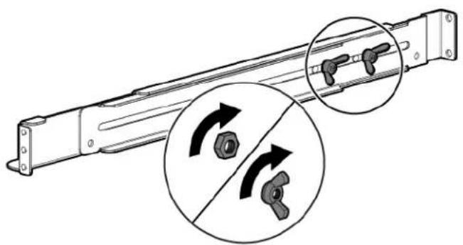
- Loosen the wing nuts or hex nuts, and then extend the brackets to the desired length.
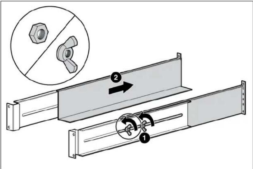
- Insert screws through the rack into the mounting rail and the front of each mounting bracket.

- Install cage nuts or clip nuts into the rear of the rack.
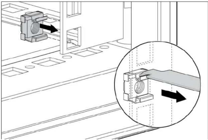
- Insert screws through the mounting rail into the cage nuts or clip nuts.

- Tighten the wing nuts or hex nuts.

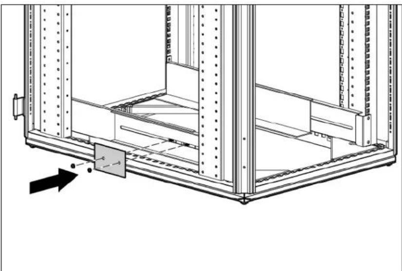
- Install the reinforcement plates using hex nuts. Wait until the unit is installed and the brackets are adjusted before tightening the nuts.
Installing rack rails for the 1U battery pack

WARNING: To reduce the risk of personal injury or damage to the equipment, be sure that:
• The leveling feet are extended to the floor. • The full weight of the rack rests on the leveling feet. • The stabilizing feet are attached to the rack if it is a single-rack installation. • The racks are coupled together in multiple-rack installations.
- Only one component is extended at a time. A rack may become unstable if more than one component is extended for any reason.

IMPORTANT: Mounting hardware for square- and round-holed racks is included in the battery pack kit.
To install the mounting rails for the 1U DirectFlow Battery Pack:
- Loosen the wing nuts or hex nuts, and then extend the brackets to the desired length. For rack shipping or relocation, ensure hex nuts are used in the rail supports.

- Install the screws through the rack into the mounting rail and the front of each mounting bracket.

- Install cage nuts or clip nuts into the rear of the rack.

- Do one of the following:
- For a stationary rack installation, install the screws through the mounting rail into the cage nuts or clip nuts.


CAUTION: When shipping or relocating a rack with installed components, always use the shipping bracket to secure the unit.
- For rack shipping or relocation, install the shipping brackets at the rear of each rail.

- Tighten the wing nuts or hex nuts.
Installing rack rails for the 3U battery pack

WARNING: To reduce the risk of personal injury or damage to the equipment, be sure that:
• The leveling feet are extended to the floor. • The full weight of the rack rests on the leveling feet. - The stabilizing feet are attached to the rack if it is a single-rack installation. • The racks are coupled together in multiple-rack installations. - Only one component is extended at a time. A rack may become unstable if more than one component is extended for any reason.

IMPORTANT: Mounting hardware for square- and round-holed racks is included in the battery pack kit.
To install the mounting rails for the 3U DirectFlow Battery Pack:
- Loosen the wing nuts or hex nuts, and then extend the brackets to the desired length.
For rack shipping or relocation, ensure hex nuts are used in the rail supports.

- Install screws through the rack into the mounting rail and the front of each mounting bracket.

- Install cage nuts or clip nuts into the rear of the rack.
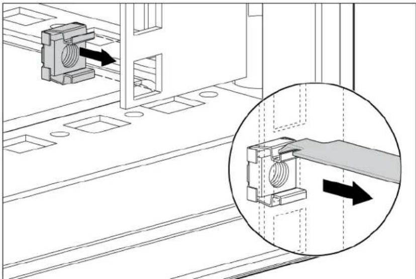
- Do one of the following:
- For stationary rack installation, install the screws through the mounting rail into the cage nuts or clip nuts.


CAUTION: When shipping or relocating a rack with installed components, always use the shipping bracket to secure the unit.
- For rack relocation or shipping, install the shipping brackets at the rear of each rail.

- Tighten the wing nuts or hex nuts.

- Install the reinforcement plates using hex nuts. Wait until the unit is installed and the brackets are adjusted before tightening the nuts.

Installing battery packs
The HP DirectFlow Battery Pack can be installed to provide extended run-time. The HP DirectFlow VRLA Battery Pack (3U) consists of a four-battery string in a 3U chassis. The HP R12000 and R18000 DirectFlow 1U Lithium-ion Battery Packs consist of an eight lithium-ion battery string in a 1U chassis. Each battery pack can connect directly to a power unit and optionally to another battery pack that is the same battery type and rack unit (U) height. Up to two battery packs can be connected in series.
Before installing any battery packs, see "Powering down the UPS (on page 33)."
Powering down the UPS
To power down an existing UPS configuration that includes battery packs, see "Powering down the UPS and battery packs (on page 80)."
To power down the UPS:
- Power down all load devices.
- Press the ESC button for 3 seconds, then press the Enter button to place the UPS in Bypass mode.
- Disconnect the power unit from utility power.
- Wait at least 5 minutes for the UPS internal circuitry to discharge and power down.
Installing the 1U battery pack
Before installing the unit, review and adhere to all warnings provided in "Precautions (on page 18)."

WARNING: To reduce the risk of personal injury or equipment damage due to weight considerations, first load the empty battery pack chassis into the rack, and then install the battery modules in the chassis.
Mount the battery pack directly below the UPS without a U gap.
To install the battery pack:
- Power down the UPS before installing the battery packs. For more information, see "Powering down the UPS (on page 33)."
- Install the mounting rails.
- With one person on each side of the carton, lift the chassis and lower it to the floor in front of the rack.
- With one person on each side, lift the chassis to rail level and slide the chassis on the mounting rails. For shipping or relocating a populated rack, secure the rear of the chassis to the rails by mating the chassis slots to the shipping bracket tabs.

- Attach the chassis to the rack using the supplied screws.
To complete the installation, see the following instructions:
- Installing the lithium-ion batteries (on page 35)
- Attaching the 1U battery pack front bezel (on page 35)
- Connecting the 1U battery pack to the 1U power unit (on page 35)
- Connecting the 1U battery pack to the 2U power unit (on page 37)
- Charging lithium-ion batteries (on page 39)
Installing the lithium-ion batteries

Attaching the 1U battery pack front bezel

Connecting the 1U battery pack to the 1U power unit

IMPORTANT: Use only the Phillips 6-32, .375 screws provided in the kit to secure the connection. The UPS does not recognize the battery pack if the screws are not tightened.
To connect the battery pack to the power unit from the rear panels:
- Switch the circuit breaker on the battery pack left to the Off position.

- Connect the power cable on the power unit to the power connector on the battery pack, and then secure the cable with the Phillips 6-32, .375 screws.

- Connect the CAN bus communication cable from the DB-15 connector on the power unit to the DB-15 connector on the battery pack.

- Switch the circuit breaker on the battery pack right to the On position.
To install a second battery pack that is the same battery type and rack U height:
- Verify that the circuit breaker on the battery pack is in the left, Off position.
- Connect the DC to DC power cable from the first battery pack connector to the second battery pack connector.
Up to two packs can be connected to the power unit.
- Connect the CAN bus communication cable from the first battery pack to the second battery pack.

- Switch the circuit breaker on the battery pack right to the On position.
The DC to DC power cable is a UPS option required for connecting battery packs; the cable can be ordered on the HP website (http://www.hp.com/go/rackandpower) (HP part number AF497A).
Connecting the 1U battery pack to the 2U power unit

IMPORTANT: Use only the Phillips 6-32, .375 screws provided in the kit to secure the connection. The UPS does not recognize the battery pack if the screws are not tightened.
To connect the battery pack to the power unit from the rear panels:
- Switch the circuit breaker on the battery pack left to the Off position.

- Connect the power cable on the power unit to the power connector on the battery pack.
Pull back the retaining clip next to the power connector on the battery back in order to connect or disconnect the power cable.

- Connect the CAN bus communication cable from the DB-15 connector on the power unit to the DB-15 connector on the battery pack.

- Switch the circuit breaker on the battery pack right to the On position.
To install a second battery pack that is the same battery type and rack U height:
- Verify that the circuit breaker on the battery pack is in the left, Off position.
- Connect the DC to DC power cable from the first battery pack connector to the second battery pack connector.
Up to two packs can be connected to the power unit.
- Connect the CAN bus communication cable from the first battery pack to the second battery pack.

- Switch the circuit breaker on the battery pack right to the On position.
The DC to DC power cable is a UPS option required for connecting battery packs; the cable can be ordered on the HP website (http://www.hp.com/go/rackandpower) (HP part number AF497A).
Charging lithium-ion batteries
To connect the power unit to a grounded utility power outlet, see "Installing the R12000DF power module (on page 50)." When the UPS is in AC mode, the power unit automatically begins charging the batteries. Allow the batteries to charge for at least 5 hours.
To extend the useful life of the batteries through good maintenance practices, see "Battery care and storage guidelines (on page 80)."
Installing the 3U battery pack
Before installing the unit, review and adhere to all warnings provided in "Precautions (on page 18)."

WARNING: To reduce the risk of personal injury or equipment damage due to weight considerations, first load the empty battery pack chassis into the rack, and then install the battery modules in the chassis.
Mount the battery pack directly below the UPS without a U gap.
To install the battery pack:
- Install the mounting rails including any reinforcement plates to support the battery packs. For more information, see "Installing rack rails (on page 20)."
- Power down the power unit before installing the battery packs. For more information, see "Powering down the UPS (on page 33)."
- With one person on each side of the carton, lift the chassis and lower it to the floor in front of the rack.
- Install the mounting ears on the chassis using the screws provided.

- With one person on each side, lift the chassis to rail level and slide the chassis on the mounting rails. For shipping or relocating a populated rack, secure the rear of the chassis to the rails by mating the chassis slots to the shipping bracket tabs.
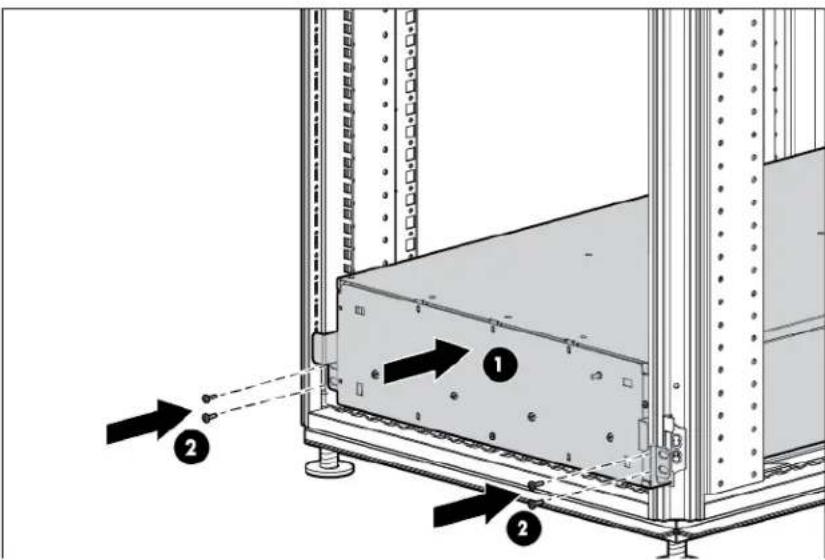
- Attach the chassis to the rack using the supplied screws.
To complete the installation, see the following instructions:
- Removing the 3U battery bracket (on page 41)
- Installing the lead acid batteries (on page 41)
- Replacing the 3U battery bracket (on page 42)
- Attaching the 3U front bezel (on page 42)
- Connecting the 3U battery pack to the 1U power unit (on page 42)
- Connecting the 3U battery pack to the 2U power unit (on page 45)
- Charging lead acid batteries
Removing the 3U battery bracket
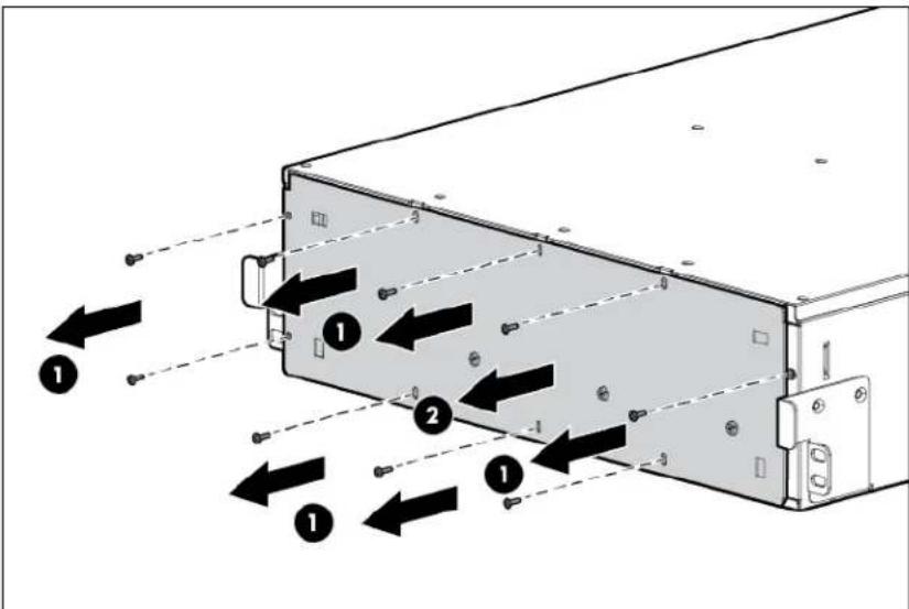
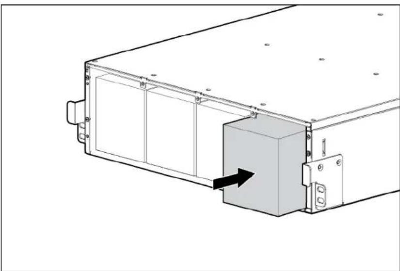
Installing the lead acid batteries

WARNING: To prevent personal injury, prepare the area and observe all materials-handling procedures when transporting a battery module. Battery modules weigh 20 kg (44 lb).
Replacing the 3U battery bracket
Attaching the 3U front bezel
Connecting the 3U battery pack to the 1U power unit

IMPORTANT: Use only the Phillips 6-32, .375 screws provided in the kit to secure the connection. The UPS does not recognize the battery pack if the screws are not tightened.
To connect the battery pack to the UPS from the rear panels:
- Switch the circuit breaker on the battery pack left to the Off position.
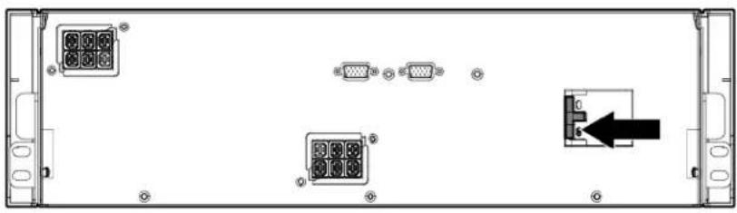
- Connect the power cable on the UPS to the power connector on the battery pack.

- Connect the CAN bus communication cable from the DB-15 connector on the UPS to the DB-15 connector on the battery pack.

- Switch the circuit breaker on the battery pack right to the On position.
To install a second battery pack that is the same battery type and rack U height:
- Verify that the circuit breaker on the battery pack is in the left, Off position.
- Connect the DC to DC power cable from the first battery pack connector to the second battery pack connector.
Up to two packs can be connected to the UPS.
- Connect the CAN bus communication cable from the first battery pack to the second battery pack.

- Switch the circuit breaker on the battery pack right to the On position.
The DC to DC power cable is a UPS option required for connecting battery packs. The cable can be ordered on the HP website (http://www.hp.com/go/rackandpower) (HP part number AF497A).
Connecting the 3U battery pack to the 2U power unit

IMPORTANT: Use only the Phillips 6-32, .375 screws provided in the kit to secure the connection. The UPS does not recognize the battery pack if the screws are not tightened.
To connect the battery pack to the UPS from the rear panels:
- Switch the circuit breaker on the battery pack left to the Off position.

- Connect the power cable on the UPS to the power connector on the battery pack.

- Connect the CAN bus communication cable from the DB-15 connector on the UPS to the DB-15 connector on the battery pack.
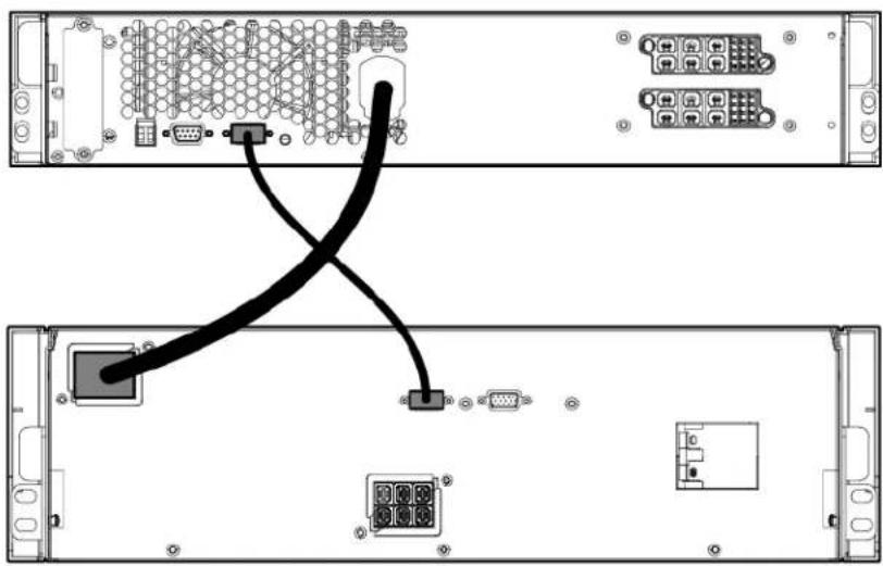
- Switch the circuit breaker on the battery pack right to the On position.
To install a second battery pack that is the same battery type and rack U height:
- Verify that the circuit breaker on the battery pack is in the left, Off position.
- Connect the DC to DC power cable from the first battery pack connector to the second battery pack connector.
Up to two packs can be connected to the UPS.
- Connect the CAN bus communication cable from the first battery pack to the second battery pack.

- Switch the circuit breaker on the battery pack right to the On position.
The DC to DC power cable is a UPS option required for connecting battery packs. The cable can be ordered on the HP website (http://www.hp.com/go/rackandpower) (HP part number AF497A).
Charging lead acid batteries
To connect the power unit to a grounded utility power outlet, see "Installing the R18000DF power module (on page 56)." When the UPS is in AC mode, the power unit automatically begins charging the batteries. Allow the UPS batteries to charge for 24 hours.
For more information on extending the useful life of the batteries through good maintenance practices, see "Battery care and storage guidelines (on page 80)."
Installing the power unit
The power unit can be installed with either an R12000DF or an R18000DF configuration.
Installing the R12000DF power unit
Before installing the unit, review and adhere to all warnings provided in "Precautions (on page 18)."
To install the power unit in the rack:
- Install the mounting rails.

CAUTION: When shipping or relocating a rack with installed components, always use the shipping bracket to secure the unit.
For shipping or relocation, secure the rear of the power unit to the rails using the shipping brackets. Be sure that each shipping bracket overlaps the corresponding tab on the power unit chassis.

- With one person on each side of the carton, lift the chassis and lower it to the floor in front of the rack.
- Install the mounting ears on the chassis using the screws provided.

- With one person on each side, lift the chassis to rail level and slide the chassis on the mounting rails.

- Attach the chassis to the rack using the supplied screws.
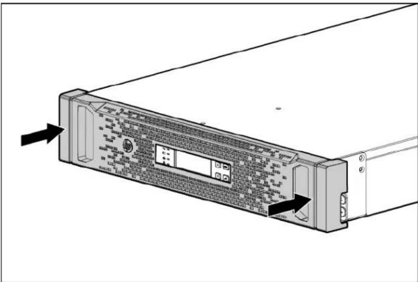
Attaching the power unit front bezel

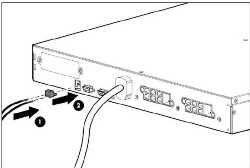
Connecting the R12000DF REPO port

WARNING: To meet the requirements stated in NEC (NFPA 70) Articles 645-10 and 645-11, a UPS installed in a computer equipment room must be connected to a REPO circuit.

IMPORTANT: The remote switch must be in the Off (open) position to enable power to the output receptacles.
Separate wire pairs should be attached to a single, normally open contact in a parallel connection. HP recommends these practices:
- Choose different colors for the positive and negative wires. Use stranded, non-shielded wire (AWG #22 - #18, or the equivalent).
- Wire the connector block before powering up the power unit to avoid unintentionally tripping the power unit.
Secure the REPO wires tightly to the rack and the rear of the power unit with tie wraps and tie wrap blocks after installing the power unit in the rack.
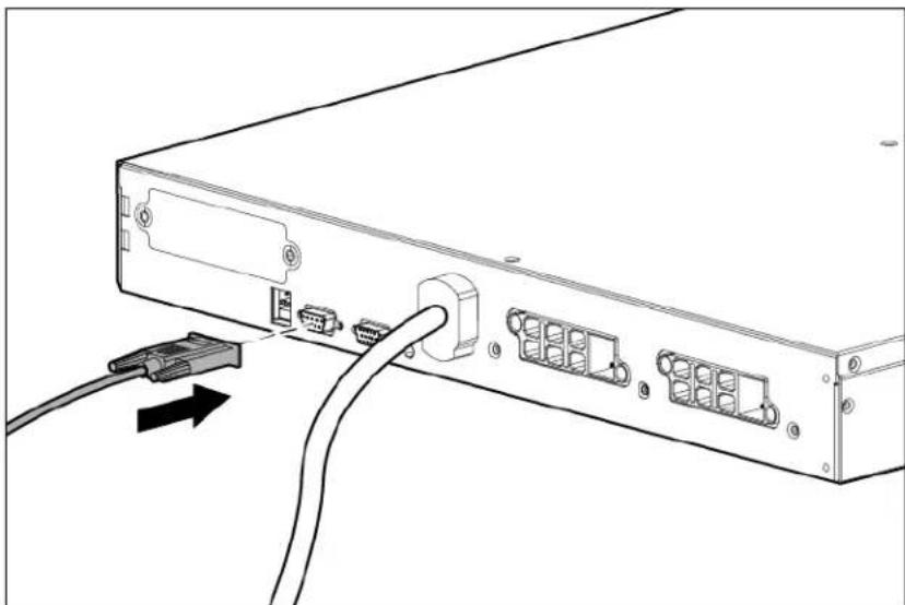
Connecting the R12000DF serial communications port
To flash the UPS firmware, or to communicate with another device, connect a computer interface cable between the power unit serial communications port and the serial port on a host computer or device.
Installing the R12000DF power module
When configuring a 1U power unit and the HP DirectFlow Input/Output Power Module with a 1U battery pack, install the power unit and the power module above the battery pack.
To install the power module in the power unit:
- Connect the power module, and then tighten the screws.
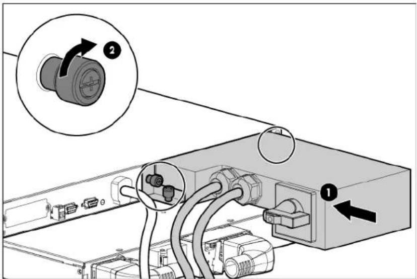
- Install the hold down bracket, and then tighten the screws.

- Ensure that the switch is in the normal, down position.

Before connecting any devices to the UPS, see "Connecting devices (on page 57)."
Installing the R18000DF power unit
Before installing the unit, review and adhere to all warnings provided in "Precautions (on page 18)."
To install the power unit in the rack:
- Install the mounting rails.

CAUTION: When shipping or relocating a rack with installed components, always use the shipping bracket to secure the unit.
For shipping or relocation, attach the shipping brackets at the rear of each rail.

- With one person on each side of the carton, lift the chassis and lower it to the floor in front of the rack.
- Install the mounting ears on the chassis using the screws provided.
- With one person on each side, lift the chassis to rail level and slide the chassis on the mounting rails. For shipping or relocation, secure the rear of the power unit to the rails using the shipping brackets. Be sure that each shipping bracket overlaps the corresponding tab on the power unit chassis.
- Attach the chassis to the rack using the supplied screws.
Attaching the power unit front bezel
Connecting the R18000DF REPO port

WARNING: To meet the requirements stated in NEC (NFPA 70) Articles 645-10 and 645-11, a UPS installed in a computer equipment room must be connected to a REPO circuit.

IMPORTANT: The remote switch must be in the Off (open) position to enable power to the output receptacles.
Separate wire pairs should be attached to a single, normally open contact in a parallel connection. HP recommends these practices:
- Choose different colors for the positive and negative wires. • Use stranded, non-shielded wire (AWG #22 - #18, or the equivalent).
- Wire the connector block before powering up the power unit to avoid unintentionally tripping the power unit.
- Secure the REPO wires tightly to the rack and the rear of the power unit with tie wraps and tie wrap blocks after installing the power unit in the rack.

Connecting the R18000DF serial communications port
To flash the UPS firmware, or to communicate with another device, connect a computer interface cable between the power unit serial communications port and the serial port on a host computer or device.

Installing the R18000DF power module
To install the HP DirectFlow Input/Output Power Module in the power unit:
- Connect the power module, and then tighten the screws.

- Ensure that the switch is in the normal, down position.

Before connecting any devices to the UPS, see "Connecting devices (on page 57)."
Connecting the UPS to utility power

WARNING: To prevent injury from electric shock or damage to the equipment:
- Plug the input line cord into a grounded (earthed) electrical outlet that is installed near the equipment and is easily accessible.
- Do not disable the grounding plug on the input line cord. The grounding plug is an important safety feature.
- Do not use extension cords.
Connect the power unit to a grounded utility power outlet.
Connecting devices

CAUTION: Do not plug laser printers into the UPS output receptacles. The instantaneous current drawn by this type of printer can overload the UPS.

CAUTION: The DirectFlow UPS is intended to supply three-phase linear/PFC loads only.
Before connecting load devices to the UPS, verify the following:
- The ratings of the devices that will be connected do not exceed the UPS capacity, which will overload the UPS. If the equipment rating is listed in amps, multiply the number of amps by the selected output voltage to determine the VA.
• The load devices are linear/PFC loads
After verification, connect the device power cords to the UPS output receptacles.
Starting power to the load
Start power to the load by placing the UPS in AC mode.

IMPORTANT: AC power must be available the first time the UPS is started.
Continuing the installation of components
HP DirectFlow Battery Packs and the HP DirectFlow UPS Management Module card can be installed for extended run-time and advanced battery management. To install these components, see the following instructions:
• Installing battery packs (on page 33) • Installing the Management Module card (on page 57)
For instructions about testing the REPO port function, see "Verifying the REPO port connection (on page 79)."
Installing the Management Module card
The HP DirectFlow UPS Management Module web interface allows remote monitoring and control of the HP DirectFlow Power Unit, HP DirectFlow UPS Management Module card, and any HP DirectFlow Battery Packs installed in the configuration. Power usage information is accessed through the network connector located on
the front of the HP DirectFlow UPS Management Module card. Multiple devices can monitor the UPS over the network connection. The Management Module card is designed specifically for the power unit. It is not intended for installation in other UPS devices.
For information about configuring access from the HP DirectFlow UPS Management Module card to the web interface, see "Accessing the Management Module (on page 63)."
For more information about accessing, signing in, and configuring the web interface software, see the HP DirectFlow UPS Management Module User Guide on the HP website
(http://www.hp.com/support/DFUPS_MM_UG_en).
Installing the Management Module card in the 1U power unit

IMPORTANT: It is not necessary to power down the UPS before installing the Management Module card.
To install the card in the UPS:
- Remove the two screws securing the cover plate on the power unit, and then slide the plate out.

- Install the Management Module card along the alignment channels in the option slot.

- If the UPS is powered up, check that the Management Module card is seated properly and receiving power by verifying that the card's Power LED light is illuminated solid green.
Connecting the serial communications cable in the 1U power unit
Connect the serial port to configure or flash Management Module card firmware or to communicate to another local device.

For the initial setup of the HP UPS DirectFlow Management Module web interface access to the management module card, use a local host computer or device connected to the serial communication port. For details, see "Accessing the Management Module (on page 63)."
Connecting the network cable to the 1U power unit
Connect the Management Module card to a network or Internet connection with an RJ-45 Ethernet cable.

A network-connected computer can be used to login to the Management Module web interface for remote access to the Management Module card and to view information about the DirectFlow UPS. To access the Management Module web interface, see "Accessing the Management Module (on page 63)."
Installing the Management Module card in the 2U power unit

IMPORTANT: It is not necessary to power down the UPS before installing the Management Module card.
To install the card in the UPS:
- Remove the two screws securing the cover plate on the power unit, and then slide the plate out.

- Install the Management Module card along the alignment channels in the option slot.

- If the UPS is powered up, check that the Management Module card is seated properly and receiving power by verifying that the card's Power LED light is illuminated solid green.
Connecting the serial communications cable in the 2U power unit
Connect the serial port to configure or flash Management Module card firmware or to communicate to another local device.

For the initial setup of the HP UPS DirectFlow Management Module web interface access to the management module card, use a local host computer or device connected to the serial communication port. For details, see "Accessing the Management Module (on page 63)."
Connecting the network cable to the 2U power unit
Connect the Management Module card to a network or Internet connection with an RJ-45 Ethernet cable.

A network-connected computer can be used to log in to the Management Module web interface for remote access to the Management Module card and to view information about the DirectFlow UPS. To access the Management Module web interface, see "Accessing the Management Module (on page 63)."
Checking the Health/Alert LED
If the Health/Alert LED illuminates red or flashes red, see "Troubleshooting (on page 89)" for more information.
Configuration
Accessing the Management Module
A local connection to the HP DirectFlow UPS Management Module card is required the first time for initial configuration.
To access the HP DirectFlow UPS Management Module locally:
- Install the Management Module card in the power unit.
a. Connect the serial communications cable to a local host computer or device. For more information, see "Connecting the serial communications cable in the 1U power unit (on page 59)" or "Connecting the serial communications cable in the 2U power unit (on page 61)." b. Connect the network cable to the Internet or network. For more information, see "Connecting the network cable to the 1U power unit (on page 60)" or "Connecting the network cable to the 2U power unit (on page 62)."
- Launch a terminal emulation program. For more information, see "Launching a terminal emulation program (on page 63)."
The POST executes on the session screen. For details about the information output by POST, see "POST (on page 64)."
- Record the IPv4 or IPv6 address for the Management Module card from the POST.
- At the prompt, press any key within 5 seconds to access and configure the Management Module Service Menu (on page 65).
-or-
Launch a telnet session to access and configure the Service Menu. For more information, see "Launching a telnet session (on page 64)."
To prepare for remote access:
- Access the Service Menu to configure the Management Module card for remote access.
- Launch a web browser on a network-connected computer or device and sign into the Management Module web interface. For more information, see "Launching a web browser (on page 71)" and "Signing into the Management Module web interface (on page 71)."
Launching a terminal emulation program
HyperTerminal is the serial communication program provided with Microsoft Windows and is used in this section as an example for setting up a terminal emulation session. If you are using another utility, the steps might be different.
To launch a terminal emulation program:
- On the host computer or device, click Start, and select Programs>Accessories>Communications>HyperTerminal.
The Connection Description window appears.
- Enter a description, select an icon for the connection, and then click OK. The Connect To window appears.
- Select the serial connector on the host computer to which the DB-9 cable is attached, and then click OK. The COM Properties window appears.
- Select the following parameter values, and then click OK.
- Bits per second—115,200
- Data bits—8
- Parity—None
- Stop bits—1
- Flow control—None
POST
When the card is powered up or reset, the boot loader performs a POST and outputs the following text.
IRQ test: PASS
Serial loopback test: PASS
HP DirectFlow UPS Management Module
NETWORK INTERFACE PARAMETERS:
IP address: 16.83.130.246
Subnet mask: 255.255.255.0
Default gateway: 16.83.130.1
HARDWARE PARAMETERS:
Module Serial number: 1US2010015
MAC address: 44:1E:A1:D1:02:14
Press any key in 5 seconds to enter the Service menu.
If an error is detected in the boot process, the Health/Alert LED illuminates or flashes. To correct the error, see "Updating the UPS firmware (on page 78)" or "Troubleshooting (on page 89)."
To access a list of commands, open Help. Enter info or vers to display information such as IP address, model and serial number, and version numbers for specific firmware.
Launching a telnet session
To launch a telnet session to access the Management Module Service Menu (on page 65):
- Enter the following command at a DOS prompt or the command line:
Telnet xxx.xxx.xxx.xxx
where xxx.xxx.xxx.xxx is the IP address of the management module.
- At the prompt, enter the user name and password.
The default user name is admin, and the default password is admin.
Navigating the Service Menu
The Management Module Service Menu provides an alternative, limited interface to the Management Module card during initial setup and when the web interface is disabled or not preferred. The menu structure textually displays measurements, warnings, and alarm messages from the Management Module card. Some
setup options and system values can be configured through the Service Menu and sent to the Management Module web interface.
All status information included in the Management Module Service Menu is also available by signing into the Management Module web interface (on page 71).
To navigate the Service Menu:
- Enter the corresponding option number at the prompt to open a submenu.
- Follow the on-screen prompts to enter or change configuration information.
- Enter 0 at the submenu prompt to go to the previous menu.
Or, enter 0 at the main menu prompt to exit the utility.
- Press the Enter key to refresh the screen.
The Management Module card resets automatically to allow configuration changes to take effect.
Service Menu
This menu only appears when accessing the Management Module card using a terminal emulation program.
| Option number | Submenu | Description |
| 1 | Module Configuration | Opens the Module Configuration submenu (on page 65) |
| 2 | Exit Exits the Service Menu and | resets the Management Module card |
Module Configuration submenu
The Module Configuration submenu opens when Module Configuration is selected from the terminal emulation Service Menu or when the telnet session is launched to access the Management Module card.
| Option number | Submenu | Description |
| 1 | System Information Displays information about the power unit, battery packs, and Input/Output Power Module | |
| 2 | System Setup Sets the date, time, and daylight saving time parameters | |
| x | Exit Without Saving Exits a menu without saving the changes | |
| s | Save New Changes and Restart | Saves changes and resets the Management Module card |
| d | Restore Configuration to Factory Defaults | Restores all parameters to default settings |
System Information submenu
| Option number | Submenu | Description |
| 1 | UPS Information Displays identification information and firmware version for the power unit and Input/Output Power Module | |
| 2 | Battery Information Displays identification information and firmware version for the battery packs | |
| 3 | UPS Status Displays power status | for the power unit and Input/Output Power Module |
| 4 | Battery Status Displays status of | the battery capacity, remaining run-time, test status and schedule, delay times, and voltage |
| 5 | Additional Information Displays | additional operating information related to the UPS such as temperature, delay time, operating mode, frequency, and limitations |
| 0 | Previous Menu Returns to the p | previous menu |
Each System Information submenu has the Refresh Data option to obtain the current status of the unit.
System Setup submenu
| Option number | Submenu | Description |
| 1 | User Accounts Enters or changes user account parameters | |
| 2 | Network Displays the Network | submenu to change network properties for the Management Module card |
| 3 | Remote Management Displays | the Remote Management submenu to change remote settings |
| 4 | UPS Management | Displays the UPS Management submenu |
| 0 | Previous Menu Returns to the previous menu | |
User Accounts submenu
| Option number | Submenu | Description |
| (1-5) | Entry Change an entry for user | login names, passwords, or administrator privileges |
| 0 | Previous Menu | Returns to the previous menu |
Network submenu
| Option number | Submenu | Description |
| 1 | IPV4 Network Settings | Enters or changes the IPV4 network properties for the Management Module card |
| 2 | IPV6 Network Settings | Enters or changes the IPV4 network properties for the Management Module card |
| 3 | Date/Time Configuration Configures the date and time | |
| 0 | Previous Menu Returns to the previous menu | |
IPV4 and IPV6 Network Settings submenus
| Option number | Submenu | Description |
| 1 | Static Address Sets the Management Module card IP address | |
| 2 | Static Subnet Mask | Sets the Management Module card subnet mask |
| 3 | Static Gateway | Sets the Management Module card defaultgateway |
| 4 | Toggle Boot Mode Toggles the | boot mode between DHCP and Static IP |
| 5 | Ping Utility | Pings the Management Module web interface |
| 0 | Previous Menu Returns to the p | previous menu |
Date/Time Configuration submenu
| Option number | Submenu | Description |
| 1 | Network Time Protocol | Enables you to configure the date and time using NTP |
| 2 | Manual Date/Time Enables you to configure the date and time manually | |
| 3 | Daylight Saving Changes | Enables you to configure daylight saving time parameters |
| 0 | Previous Menu Returns to the previous menu | |
Network Time Protocol submenu
| Option number | Submenu | Description |
| 1 | Primary NTP Server | Enables you to enter or change the IP address of the primary NTP server |
| 2 | Secondary NTP Server | Enables you to enter or change the IP address of the secondary NTP server |
| 3 | GMT Offset (time zone) Enables you to select the time zone from the table provided | |
| 4 | Update Frequency (1–24 hours) | Enables you to enter the number of hours that should pass between each date and time update |
| 5 | NTP Client | Enables you to enable or disable the NTP client |
| 6 | Accept Changes Enables you to save all changes | |
| 0 | Previous Menu Returns to the previous menu | |
Manual Date/Time submenu
| Option number | Submenu | Description |
| 1 | Change Date Enables you to enter or change the date manually | |
| 2 | Change Time Enables you to enter or change the time manually | |
| 0 | Previous Menu Returns to the previous menu |
Daylight Saving Changes submenu
| Option number | Submenu | Description |
| 1 | Enable/Disable Daylight Saving Time | Enables you to enable or disable daylight saving time |
| 2 | Change Time Offset | Enables you to configure the amount of time the clock should change for daylight saving time in your region |
| 3 | Change Daylight Saving Time Start | Enables you to configure the day and time that daylight saving should start |
| 4 | Change Daylight Saving Time End | Enables you to configure the day and time that daylight saving should end |
| 0 | Previous Menu Returns to the previous menu |
Remote Management submenu
| Option number | Submenu | Description |
| 1 | SNMP Configures SNMP managers and SNMP traps | |
| 2 | FTP | Enables or disables the FTP service |
| 3 | Emails Configures a mail server and email event notifications | |
| 4 | Session Settings Configures timeouts and retries for remote sessions | |
| 5 | Web Access Enters or changes parameters for web interface access | |
| 6 | Remote Console | Enters or changes parameters for telnet access |
| 0 | Previous Menu Returns to the previous menu | |
SNMP submenu
| Option number | Submenu | Description |
| 1 | SNMP Managers (NMS) | Enables you to select an entry to configure the SNMP managers (computers that use the HP Power MIB to request information from the management module) |
| 2 | SNMP Traps Enables you to select an entry to configure the SNMP traps receiver | |
| 0 | Previous Menu | Returns to the previous menu |
SNMP Managers (NMS) submenu
| Option number | Submenu | Description |
| 1 | IP Address Enables you to enter | or change the IP address of the SNMP manager |
| 2 | Read Community String | Enables you to enter or change the Read community string of the SNMP manager |
| 3 | Write Community String | Enables you to enter or change the Write community string of the SNMP manager |
| 4 | Access Privileges | Enables you to enter or change access privileges of the SNMP manager |
| 5 | Enable/Disable SNMP Manager | Enables you to enable or disable the SNMP manager |
| 0 | Previous Menu Returns to the p | previous menu |
| 1 | Trap Receiver IP Address | Enables you to enter or change the IP address of a server that should receive SNMP traps |
| 2 | Trap Community String | Enables you to enter or change the community strings of a server that should receive SNMP traps |
| 3 | Enable/Disable Trap | Enables or disables an SNMP traps receiver |
| 0 | Previous Menu | Returns to the previous menu |
SNMP Traps submenu
Emails submenu
| Option number | Submenu | Description |
| 1 | Change SMTP Settings | Enables you to enter or change SMTP settings in the SMTP Settings submenu (on page 69) |
| 2 | Edit An Entry Enables you to edit an email recipient entry on the Email Recipient submenu (on page 69) | |
| 0 | Previous Menu Returns to the previous menu | |
SMTP Settings submenu
| Option number | Submenu | Description |
| 1 | SMTP Server Enables you to enter or change the mail serverIP address | |
| 2 | Sender Email | Enables you to enter or change the emailaddress that messages are marked as beingsent from |
| 0 | Previous Menu Returns to the previous menu | |
Email Recipient submenu
| Option number | Submenu | Description |
| 1 | Receiver Email | Enables you to enter or change an email address that should receive email alert notifications |
| 2 | Enable/Disable Email Generation | Enables or disables the receiver of email alert notifications |
| 0 | Previous Menu Returns to the previous menu |
Session Settings submenu
| Option number | Submenu | Description |
| 1 | Session Inactivity Timeout Enables you to enter the number of minutes the Management Module web interface should wait before terminating an inactive session | |
| 2 | Login Retries | Enables you to enter the number of times a user can unsuccessfully log in to the Management Module web interface before the account is locked |
| 3 | Lock-out Period (After x Retries) | Enables you to enter the number of minutes to wait between an unsuccessful login and a new login attempt |
| 4 | Reset Login Retry Count For All Users | Enables you to reset all locked out sessions |
| 0 | Previous Menu Returns to the previous menu | |
Web Access submenu
| Option number | Submenu | Description |
| 1 | Enable/Disable Web Access Turns web access on or off | |
| 2 | HTTP/HTTPS Configuration | Configures the port for HTTP or HTTPS |
| 0 | Previous Menu Returns to the previous menu | |
Remote Console submenu
| Option number | Submenu | Description |
| 1 | Enable/Disable Telnet Enables or disables telnet access | |
| 2 | Change Telnet Port Changes the port for telnet | |
| 0 | Previous Menu Returns to the previous menu |
Configuring the Management Module card for remote access
Use the Management Module Service Menu to configure the minimum settings required to access the Management Module card remotely using the web interface. You can configure other settings using this utility in conjunction with a terminal emulation program.
The IP address assigned to the Management Module card must be fixed. If the IP address changes:
• The UPS loses communication with the Management Module web interface. • You can lose track of the Management Module card URL.
To configure the Management Module network parameters:
- If your network is configured with a DHCP server, the network settings are automatically assigned. Verify and note the assigned values.
- If your network is not configured with a DHCP server:
a. On the Main menu, enter 1 at the prompt to open the Module Configuration submenu. b. Enter 2 at the prompt to enter the Network Configuration submenu. c. Enter 1 at the prompt to enter the Network Settings submenu. d. In the Network Settings submenu, change the mode used to acquire a network IP address to static IP.
You can also change the IP address, subnet mask, and default gateway of the Management Module card.
Launching a web browser
To launch a web browser to access the Management Module web interface:
- If necessary, configure the Management Module card by:
a. Launching a terminal emulation program (on page 63). b. Configuring the Management Module card for remote access (on page 70).
- Launch a supported browser.
- In the browser Address field (Microsoft Internet Explorer) or the Location field (Mozilla and Firefox), enter:
http://xxx.xxx.xxx.xxx
-or-
https://xxx.xxx.xxx.xxx
where xxx.xxx.xxx.xxx is the IPv4 or IPv6 address of the Management Module card. The login screen appears.
- Sign in through the web browser.
For a complete list of the browser requirements, see "Web interface requirements (on page 71)."
Web interface requirements
The following table lists the minimum requirements necessary to operate the web interface.
| OS running Windows | Browser | Browser version |
| Windows XP | Internet Explorer 8 | |
| Windows Server 2003 | Internet Explorer 8 | |
| Windows Vista | Internet Explorer 8 | |
| Windows Server 2008 | Internet Explorer 8 | |
| Windows 7 | Internet Explorer 8 | |
| Windows 7 | Internet Explorer 9 | |
| Win Server 2008 R2 | Internet Explorer 9 | |
| Win Vista SP2 | Internet Explorer 9 | |
| Windows Server 2008 SP2 | Internet Explorer 9 |
| OS running Linux | Browser | Browser version |
| RHEL 6.3 | Firefox 10.0.5 | |
| RHEL 5.8 | Firefox | 3.6.26 |
| SLES 10 SP4 | Firefox 3.6.13 | |
| SLES 11 SP2 | Firefox 10 | |
| HPUX | Firefox 3.5.9 |
Signing into the Management Module web interface
To sign in to the Management Module web interface:
- Enter the user name in the User Name field. The default user name is admin.
- Enter the password in the Password field. The default password is admin.
Passwords are case-sensitive.
- Click Sign In. The HP DirectFlow UPS Management Module web interface appears.
-or-
Click Clear to clear the credentials.
For information about configuring and using the Management Module, see the HP DirectFlow UPS Management Module User Guide on the HP website (http://www.hp.com/support/DFUPS_MM_UG_en).

The web interface graphically displays various measurements and warning and alarm messages from the Management Module card. Also, system values and power fail settings can be configured through the web interface and sent to the Management Module card.
Configuring the power unit
Configure the power unit for options such as utility and generator power levels and usage, SNMP traps, testing parameters, date and time, display language, and machine functions using the front panel controls for the UPS operations (on page 73).
UPS operations
Navigating UPS menu options
To navigate the options menu using the power unit front panel controls and LCD screen:
- Press the Up or Down arrow to activate the menu options.
- Press the Up or Down arrow to scroll to a menu or option.
- Press the Enter button to enter a submenu or select a specific option.
- Press the ESC button to cancel or return to the previous menu.
The control panel automatically dims after a long period of inactivity. Press any button to restore the screen. To view the complete menu structure, see "UPS menu options (on page 73)."
UPS menu options
| Main menu | Submenu | Display information or menu option | Description |
| UPS Status | Current Setting | VOUT_SET=480V-Y | Output voltage setting of wiring type |
| — | — I/O Module: AF486A | 480V NEMAL22 | Input/output power module type |
| — | Battery Status | VBAT=xxxV, xxx%, Boost | Battery voltage |
| — | — Charge Inhibit Inhibi | charging batteries | |
| — | — | BP=LA_3U, 2 | Battery pack type |
| — | Service Life Time | xxxxxDAYS xxHOURS | Period that UPS has already operated |
| Event Log | xx-DD/MM/YYYYHH:MMAlarm 1 | — | Date, time, and type of a current alarm |
| Measurements | — — | Measurements display | |
| Test/Reset | Test Battery | Press Enter for yes, or ESC for no | Runs a battery test |
| — | Clear Event Log | Press Enter for yes, or ESC for no | Clears the event log |
| — | Test Display | In progress | Tests the display |
| — | Set Factory Default | Press Enter for yes, or ESC for no | Resets to the factory default settings |
| — | Reset Batt Forecast | Press Enter for yes, or ESC for no | Resets the battery forecast parameter |
| Settings | Language | English* | Language displayed |
| — | — French | — | |
| — | — German | — | |
| — | — | Italian | — |
| — | — | Spanish | — |
| — | Date & Time | DD/MM/YYYY hh:mm | Baseline date and time of UPS |
| — | Backlight Off After | None | Time before display back light shuts off |
| — | — xxMin — | ||
| — | Battery Test Period No Test Period of time for running automatic battery test | ||
| — | — 7 Days — | ||
| — | — 14 Days — | ||
| — | — 30 Days — | ||
| — | — 60 Days — | ||
| — | Battery Test Method | Energy Recycle | Battery test runs in AC mode |
| — | — To Battery Mode* Battery test runs in Battery mode | ||
| — | Power On | Automatically* | UPS turns on with AC power input |
| — | — | By On key | UPS turns on by pressing On button |
| — | Start-up Delay | Random* | Random startup delay |
| — | — xxxxxms Timed startup delay | ||
| — | Recovery Delay | Random* | Random recovery delay |
| — | — xxxxxms Timed recovery delay | ||
| — | Delay Charge | None* | No delay for charging batteries |
| — | — | xxxxxs | Timed delay for charging batteries |
| — | Function Of Machine | UPS* | Unit functions with battery backup |
| — | — | ACC Only | Unit functions as an active current conditioner without battery backup |
| — | Load Level For ACC | Always on | Active current correction on |
| — | — | xxx%* | Active current correction percentage of load |
| — | — | Always off | Active current correction off |
| — | Charger Limit Gen | 1100W | Charger limit while on generator |
| — | — 555W | — | |
| — | — 190W | — | |
| — | — | No Charge* | — |
| — | Charger Limit-Uti | 1100W | Charger limit while on utility power |
| — | — 555W* | — | |
| — | — 190W | — | |
| — | — No Charge | — | |
| — | Free Run Frequency | 60Hz* | Run frequency in AC mode |
| — | — | 50Hz | — |
| — | Input Source | Util Only | AC input from utility power source only |
| — | — | Util & Gen* | AC input from utility and generator power sources |
| — | On-Gen Duration | 30 min* | Time period that unit uses generator power settings |
| — | — 1 hr — | ||
| — | — 2 hr — | ||
| — | — 4 hr — | ||
| — | Run Time Limitation | Yes | Enable the maximum battery run time limitation |
| — | — No* — | ||
| Identification | PU P/N: — Power unit | model | |
| — | PU S/N: — Power unit | serial number | |
| — | PU SYS FW: — Power | unit system firmware | version |
| — | PU PWR FW: | — | Power unit power firmware version |
| — | BP1 P/N: — Battery pack 1 model (closest | to power unit) | |
| — | BP1 S/N: | — | Battery pack 1 serial number |
| — | BP1 FW: | — | Battery pack 1 firmware version |
| — | BP2 P/N: | — | Battery pack 2 model |
| — | BP2 S/N: | — | Battery pack 2 serial number |
| — | BP2 FW: | — | Battery pack 2 firmware version |
* An asterisk indicates the factory default setting.
Configuring the battery charge power levels
Different battery charge power levels can be set in the power unit for utility and generator input sources. A higher charge power level like 1100 W or 550 W can be set for utility input, and a lower charge level, 190 W or 0 W, can be set for generator input to reserve AC power for loads while running on generator input. By default, the power unit uses a built-in algorithm to determine when to switch battery charge power levels. For instance, when there is a power outage the UPS transfers from AC mode to Battery mode. If the input AC becomes available before 10 seconds or after 60 seconds, the power unit automatically remains at the charge power level defined for utility input. However, if the input AC becomes available again between 10 and 60 seconds, the power unit switches to the battery charge power level defined for generator input. The power unit remains at the generator charge power level until the defined on-generator time period expires, and then the power unit switches back to the charge power level defined for utility input.
To set the power unit battery charge power levels from the Settings menu:
- Select Input source, scroll to Utility & Gen, and then press Enter.
Utility & Gen is the default setting. To disable the built-in algorithm, select Utility Only.
- Select Charger Limit-Gen, scroll to the wattage, and then press Enter. The default charger limit wattage setting is 0 W.
- Select Charger Limit-Uti, scroll to the wattage, and then press Enter. The default charger limit wattage setting is 555 W.
- Select On-Gen Duration, scroll to the time period, and then press Enter. The default on-generator duration is 30 minutes.
The Management Module can override the default settings for charge power level switching by initiating an immediate switch to the generator charge power level if the Management Module receives a SNMP request with an on-generator command from a generator system. The on-generator command must be received within 15 minutes of the AC input power becoming available again or the power unit will use the default time periods. The power unit will switch back to the utility charge power level either after an off-generator command is received or after the defined on-generator period of time expires. To set up the Management Module to receive generator commands, see the HP DirectFlow UPS Management Module User Guide.
Changing the language
To change the display language on the power unit:
- Scroll through the main menu and select Settings.
- Select Language.
- Press the Up or Down arrow to scroll to the language.
- Press the Enter button to save the change.
Working with UPS modes of operation
The UPS modes of operation result from current operating conditions and the parameters that provide power protection to connected load devices. Some mode options can be set or adjusted using the UPS menu options (on page 73).
The UPS has the following modes of operation:
• AC mode (on page 76) • Battery mode (on page 77) • Bypass mode (on page 77)
AC mode
When the UPS operates in AC mode:
• Power is available at the UPS receptacles. • The power unit actively filters and mitigates harmonics and power factor. • The power unit charges the batteries as necessary. • The UPS transfers to Battery mode (on page 77) or Bypass mode (on page 77) as necessary.
An audible buzzer sounds briefly to indicate the UPS is powering up when the power unit is connected to utility power. If no utility power is available, the UPS might enter Battery mode.
Battery mode
When another power source is unavailable, the UPS automatically operates on battery power in Battery mode:
• Power is available at the UPS receptacles for a minimum of 60 seconds per battery pack. • The UPS automatically transfers back to AC mode (on page 76) when that input is available again.
To turn the UPS completely off from Battery mode, press the Off button for 3 seconds.
Bypass mode
The UPS automatically enters Bypass mode when one of the following conditions occurs:
- Extended overload • Over temperature
- Output short
- Hardware failure
In Bypass mode, utility power continues to be passively filtered by the UPS. To troubleshoot operating problems or conditions that might transfer the UPS into Bypass mode, see "Troubleshooting (on page 89)." To transfer from Bypass mode to AC mode (on page 76) after any operating problems are resolved, press the On button for 3 seconds.
Maintenance
Updating the UPS firmware
Download the HP DirectFlow Upgrade Utility (Upgrade_HP_v00_1b_b11282013.exe) from the HP website (http://www.hp.com/go/rackandpower).
To update the UPS firmware:
- From AC mode, move the CAM switch on the power module to the Bypass setting.
- Connect a local host computer or device to the power unit serial communications port. For more information, see either "Connecting the R12000DF serial communications port (on page 50)" or "Connecting the R18000DF serial communications port (on page 55)."
- Launch the utility.
- Click Upgrade Now.
If you receive an error, verify the UPS is in Bypass mode.

During upgrade, the utility:
- Verifies communication between the power unit and host computer or device
- Sets the UPS in Bypass mode for the upgrade process
- Flashes each component individually in order
- Displays a progress line
- From Bypass mode, move the CAM switch on the power module to the AC setting.
By default, all UPS components except the Management Module card are flashed during the upgrade. For more information about using a utility to update or configure the Management Module card, see the HP DirectFlow UPS Management Module User Guide.
Restoring power after a REPO activation

IMPORTANT: If the UPS was operating on battery power when the remote switch was closed, no power is available to the load devices until utility power is restored and the UPS has been manually powered up.
To restore power to the load devices after the REPO feature is activated:
- Connect the REPO port. To connect a REPO port for an R12000DF power unit, see "Connecting the R12000DF REPO port (on page 49)." To connect a REPO port for an R18000DF power unit, see "Connecting the R18000DF REPO port (on page 54)."
- Press the On button after the AC source is reconnected to the UPS.

IMPORTANT: Pressing and holding the On button without utility present normally initiates a battery start and the UPS assumes the load. If the On button is pressed and a REPO is detected, the battery start is inhibited and the UPS is not able to assume the load. The electronics module fan spins and the UPS fault LED and an audible alarm is active as long as the On button is held.
To power down the entire network in the event of an emergency, the REPO ports of multiple power units can be connected to a single switch.
Verifying the REPO port connection

IMPORTANT: While testing, operate connected equipment in a safe test mode so the effects do not disrupt critical operations.
Verify the connection after connecting the REPO port:
- Initiate a REPO by closing the REPO contact.

CAUTION: If the polarity is reversed while connecting the REPO port, the UPS powers up normally.
- Verify proper connection of the REPO port:
a. Press the On button to power up the UPS. b. Disconnect the REPO port. c. Reconnect the REPO port. If the polarity is correct, the REPO connectors can be disconnected, and then reconnected, without initiating a REPO. d. Verify that the UPS remains in AC mode (on page 76). e. If a REPO is initiated, the polarity is reversed. Check and correct the connections.
Powering down the UPS and battery packs
To power down the UPS:
- Power down all load devices.
- Press the ESC button for 3 seconds, and then press the Enter button to place the UPS in Bypass mode.
- Disconnect the power unit from utility power.
- Wait at least 60 seconds for the UPS internal circuitry to discharge and power down.
- If battery packs are installed, turn the circuit breaker switches left to the Off positions.
Replacing the batteries
To replace the batteries:
- Read and observe the requirements in "Important battery safety information (on page 80)" and "Battery care and storage guidelines (on page 80)."
- Follow the instructions in "Battery replacement procedure (on page 81)."
Important battery safety information
See the complete regulatory compliance notices in Safety and Compliance Information for Server, Storage, Power, Networking, and Rack Products on the HP website
(http://www.hp.com/support/Safety-Compliance-EnterpriseProducts). In addition, follow the safety precautions that are specific to this device.
Replace all battery modules at the same time with the same type of batteries originally installed in the battery pack.
Battery care and storage guidelines
HP recommends the following care and storage practices:
- Keep the area around the UPS clean and dust-free. If the environment is very dusty, clean the outside of the UPS regularly with a vacuum cleaner.
- Maintain the ambient temperature at 25°C (77°F). • If storing a UPS for an extended period, recharge the batteries every 6 months. a. Connect the power unit to utility power. b. Allow the UPS to charge the batteries to 100% capacity. c. Update the battery recharge date label.

CAUTION: Because of the short shelf life of the batteries, avoid storing a battery spare as a backup. Do not maintain an inventory of spare batteries on site unless a procedure to keep these batteries charged while in storage is implemented.
Battery replacement procedure
To ensure confidence and meet expectation of the UPS performance, HP recommends replacing the battery at the service life point of 3 years for the 3U lead acid batteries and 4 years for 1U lithium-ion batteries.
Factors that affect battery service life include operating temperature, the depth and frequency of battery discharges, and charging control. Battery performance also slightly degrades later in the battery service life.
Replacing lead acid battery modules
All four 3U battery modules must be replaced at the same time.
To remove the batteries from the battery pack:
- Remove the front bezel.
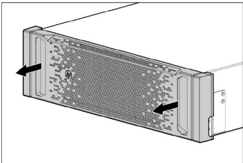
- Remove the battery bracket.

3. Remove the battery modules.

To replace the component, reverse the removal procedure.

IMPORTANT: Charge the lead acid batteries for at least 24 hours before supplying backup power to devices. The batteries charge to:
• 80 percent capacity within 3 hours • 100 percent capacity within 24 hours
Replacing lithium-ion battery modules
To remove the batteries from the battery pack:
- Remove the front bezel.

- Remove the battery modules.

To replace the component, reverse the removal procedure.

IMPORTANT: Charge the lithium-ion batteries for at least 5 hours before supplying backup power to devices. The batteries charge to 100 percent capacity within 5 hours.

IMPORTANT: Lithium-ion batteries in excess of 100 Wh are classified as Class 9 Dangerous Goods and must be packaged and shipped in accordance with International or domestic regulations. For more information, see the special handling instructions that are required for returning the lithium-ion battery modules that were provided in the spare lithium-ion battery module spare kit.
Replacing the 1U battery pack
To remove the 1U battery pack:
- Power down the UPS and battery packs. For more information, see "Powering down the UPS and battery packs (on page 80)."
Do not remove the battery pack when the UPS is in Battery mode.
- Disconnect all cabling.
- Remove the lithium-ion battery modules from the battery pack. For more information, see "Replacing lithium-ion battery modules (on page 82)."
- Remove the screws securing the battery pack, disengage any shipping brackets from the rear of the battery pack, and then slide the module out.
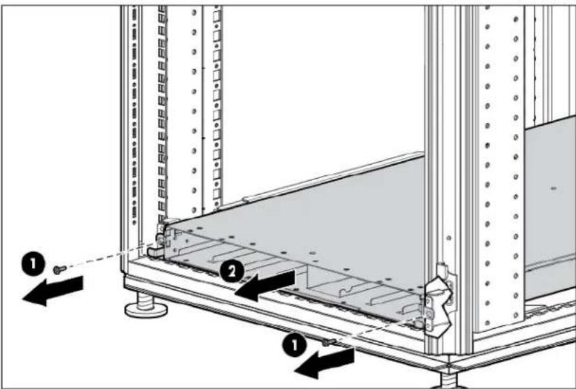
To replace the battery pack, see "Installing battery packs (on page 33)."
Replacing the 3U battery pack
To remove the 3U battery pack:
- Power down the UPS and battery packs. For more information, see "Powering down the UPS and battery packs (on page 80)."
Do not remove the battery pack when the UPS is in Battery mode.
- Disconnect all cabling.
- Remove the lead acid battery modules from the battery pack. For more information, see "Replacing lead acid battery modules (on page 81)."
- Remove the screws securing the battery pack, disengage any shipping brackets from the rear of the battery pack, and slide the module out.
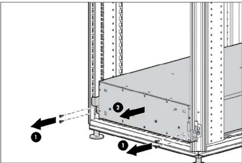
To replace the battery pack, see "Installing battery packs (on page 33)."
Replacing the Management Module card
To remove the Management Module card, slide the card out of the option slot in the power unit.

To replace the Management Module card, see "Installing the Management Module card (on page 57)."
Replacing the power module
To remove the power module from the power unit:
- Power down the UPS and any battery packs. For more information, see "Powering down the UPS and battery packs (on page 80)."
- Turn the switch clockwise to the left, Bypass position.
- Loosen the four screws.

- Disconnect the unit, and then remove the module from the power unit.
To replace the R12000DF power module, see "Installing the R12000DF power module (on page 50)." To replace the R18000DF power module, see "Installing the R18000DF power module (on page 56)."
Replacing the 1U power unit
To remove the power unit:
- Power down the UPS and any battery packs. For more information, see "Powering down the UPS and battery packs (on page 80)."
- Remove the Input/Output Power Module. For more information, see "Replacing the power module (on page 85)."
- Disconnect all cables attached to the power unit connectors.
- Remove the front bezel from the power unit.

- Remove the screws securing the power unit, disengage any shipping brackets from the rear of the power unit, and then slide the module out.

To replace the power module, see "Installing the R12000DF power unit (on page 47)."

IMPORTANT: Replacing the power unit might require power management software to be restarted or reconfigured.
Replacing the 2U power unit
To remove the power unit:
- Power down the UPS and any battery packs. For more information, see "Powering down the UPS and battery packs (on page 80)."
- Remove the Input/Output Power Module. For more information, see "Replacing the power module (on page 85)."
Slide the power module away from the power unit. Temporarily attach the power module to the battery pack by inserting screws on the power module into empty holes on the top of the battery pack. Tighten the screws slightly to secure the power module to the battery pack.
- Disconnect all cables attached to the power unit connectors.
- Remove the front bezel from the power unit.

- Remove the screws securing the power unit, disengage any shipping brackets from the rear of the power unit, and then slide the module out.

To replace the power module, see "Installing the R18000DF power unit (on page 52)."

IMPORTANT: Replacing the power unit might require power management software to be restarted or reconfigured.
Troubleshooting
LED and audible alarm troubleshooting
The DirectFlow UPS is designed for durable, automatic operation and also to alert you whenever potential operating problems might occur. The alarms do not necessarily mean that the output power is affected; instead, they are often preventive alarms intended to alert you of a possible condition. An operating problem might trigger the following activity:
• An audible alarm announced by a buzzer in the power unit • LEDs illuminating, flashing, or not illuminating on the control panel • Alarm descriptions that appear on the LCD screen - Alarm entries or related event entries that appear on the Alarms screen or the Event Log screen of the Management Module web interface
The following table describes typical alarms and conditions that are accompanied by LED behavior on the power unit front panel.
| LED | LED status | Alarm type |
| UPS fault LED | Solid red light indicates a UPS fault | Long buzzer (5 sec) |
| Bypass mode LED | Solid green light indicates the UPS is in Bypass mode | none |
| Battery mode LED | Solid yellow light indicates the UPS is in Battery modeFlashing yellow light indicates low battery condition | Short buzzer (.1 sec) upon entering Battery mode or low battery statusLong buzzer upon transferring out of Battery mode (5 sec) or low battery condition (1 sec) |
| Input LED | No light indicates utility power is out of operating range | none |
| Power LED (on Management Module card) | No light indicates the card is not active | none |
| Health/Alert LED (on Management Module card) | Red light indicates an error in the card boot process | none |
The alarm descriptions table describes typical alarms and conditions that appear on the power unit front panel LCD screen in the UPS event log. If an alarm appears with a service code, see "HP contact information (on page 120)."
To check the event log for a list of active alarms:
- Press the Enter button on the front panel display to activate the menu options.
- Press the down arrow button until the Event Log menu appears.
- Press the Enter button to display the list of alarms and conditions.
Alarm descriptions and SNMP trap codes
The following table describes power unit alarms and indicates the associated trap codes used by the Management Module.
| Trap code | Alarm name | Alarm description | Alarm type |
| 0 | Test trap | This alarm is used for testing traps. | Test trap |
| 1 | Charger fault | The charger voltage or current is out of the valid charger threshold. | Critical |
| 2 | Fan fault | A fan is locked or abnormal. | Critical |
| 3 | Over temperature 1 | The charger temperature exceeded the limit. | Critical |
| 4 | Over temperature 2 | The D2D temperature exceeded the limit. | Critical |
| 5 | Over temperature 3 | The inverter temperature exceeded the limit. | Critical |
| 6 | Over temperature 4 | The bypass SCR temperature exceeded the limit. | Critical |
| 7 | Over temperature 5 | The ambient temperature exceeded the limit. | Critical |
| 8 | Over temperature 6 | The 1U battery pack cell temperature exceeded the limit during charging. | Critical |
| 9 | Over temperature 7 | The 1U battery pack charger temperature exceeded the limit. | Critical |
| 10 | Over temperature 8 | The 1U battery pack MOSFET switches temperature exceeded the limit. | Critical |
| 11 | Over temperature 9 | The 1U battery pack cell temperature exceeded the limit during discharging. | Critical |
| 12 | DC bus high/low | The DC bus voltage is less than or greater than the valid temperature. | Critical |
| 13 | Soft-start fault | The +/- DC bus voltage cannot be boosted to the default level. | Critical |
| 14 | Bus OVP | The DC bus exceeded the voltage upper threshold. | Critical |
| 15 | Power DSP fault | The power DSP crashed. | Critical |
| 16 | Inverter fault | There is a fault in the inverter circuit. | Critical |
| 17 | DC AUX power fault | There is a fault in the DC auxiliary power circuit. | Critical |
| 18 | AC AUX power fault | There is a fault in the AC auxiliary power circuit. | Critical |
| 19 | Input volt not OK | The utility voltage is out of the usable voltage range. | Critical |
| 20 | Input freq not OK | The utility frequency is out of the usable frequency range. | Critical |
| 21 | On battery | The UPS is operating in battery discharging mode. | Critical |
| 22 | On bypass | The UPS is not powered on and the output is supplied by utility directly. | Critical |
| 23 | Bypass fault | There is a fault in the bypass SCR circuit. | Critical |
| 24 | Output fault | There is a fault in the inverter SCR circuit. | Critical |
| 25 | Output overload | Load levels are at, or exceeded, the overload threshold. | Critical |
| 26 | Output short | The output is shorted. | Critical |
| 27 | Low battery Battery time | remaining is lower than the battery low warning level defined for the UPS. | Critical |
| 28 | Battery bad A battery in | side the battery pack is aging or abnormal. | Critical |
| 29 | REPO initiated | The external REPO contacts on the power unit have been activated. | Critical |
| 30 | DB missing | The distribution box (input/output power module) was not connected to the power unit or the signal was lost. | Critical |
| 31 | BM missing | A battery module is missing. | Critical |
| 32 | Battery low shutdown | Shut down the power unit due to low batteries. | Critical |
| 33 | Overload shutdown | Shut down the power unit due to overload. | Critical |
| 34 | Wiring fault | The input wiring of the 3-phase power unit is not correct. | Critical |
| 35 | Attach >2 BP | More than two battery packs are connected to the same power unit. | Warning |
| 36 | Not same BP type | Two different battery pack types are connected to the same power unit. | Warning |
| 37 | BP not compatible The firm | mware version of a battery pack is not compatible with the power unit. | Warning |
| 38 | BM not compatible | The firmware version of a battery module is not compatible with the battery pack. | Warning |
| 39 | BP cable missing | The signal cable between the power unit and the battery pack is not connected. | Warning |
| 40 | BP disconnected | The DC power cable is missing or the battery pack breaker is not in the on position. | Warning |
| 41 | BP comm loss | The communication between the battery pack and the power unit is lost. | Warning |
| 42 | Internal comm loss | The power unit MCU lost communication with the power unit DSP. | Warning |
| 43 | On manual bypass | Turn the switch on the back of the power unit and the load is supplied by utility directly. | Warning |
| 44 | Self-diagnosis fault | The inverter voltage cannot be boosted to the default level. | Warning |
| 45 | PWR not compatible | The firmware version of the power DSP is not compatible with the system MCU. | Warning |
| 46 | ACC active | ACC circuit is currently active. | Informative |
| 47 | Manual power on | Press and hold the Enter button to turn on the power unit. | Informative |
| 48 | Manual power off | Press and hold the ESC button to turn off the power unit. | Informative |
| 49 | Remote power on | Use this command to turn on the power unit. | Informative |
| 50 | Remote power off | Use this command to turn off the power unit. | Informative |
| 51 | Testing battery | The batteries are being tested. | Informative |
| 52 | Battery is aging | The battery is aging and cannot support sufficient battery runtime. | Informative |
| 53 | BP not ready 1 | The 1U battery pack is performing self-diagnosis and the battery modules are not ready. | Informative |
| 54 | BP not ready 2 | The 1U battery pack is being reconfigured and the battery modules are not ready. | Informative |
| 55 | BP not ready 3 The voltage | ge between two parallel 1U battery packs is too high and the battery packs are not ready. | Informative |
| 56 | BP not ready 4 | The 1U battery pack has an internal communication failure and the battery pack is not ready. | Informative |
| 57 | BP MOSFET fault The 1U | battery pack MOSFET that puts battery modules in series is damaged. | Critical |
| 58 | BP discharge OCP | Over current protection was used for a 1U battery pack while discharging. | Critical |
| 59 | BP charge OCP | Over current protection was used for a 1U battery pack while charging. | Critical |
| 60 | BP short circuit | The 1U battery pack shorted while discharging. | Critical |
| 61 | BP over voltage The 1U | battery pack exceeded the cell voltage limit while charging. | Critical |
| 62 | Under temperature 1 | The 1U battery pack cell temperature is too low and cannot be charged. | Critical |
| 63 | Under temperature 2 | The 1U battery pack cell temperature is too low and cannot be discharged. | Critical |
| 64 | Timeout shutdown | The power unit shut down because the battery pack exceeded the runtime (70 seconds for a single battery pack and 5 minutes for two battery packs). | Critical |
| 65 | 2BPs not compatible | The firmware versions inside two battery packs are not compatible with each other. | Warning |
| 66 | BM into deep sleep | The battery module inside the 1U battery pack is in deep sleep mode to prevent being deeply discharged. In this condition, the 1U battery pack cannot support the load. | Warning |
| 67 | Charger start fault | The UPS starts the charger but the charger voltage cannot reach the required voltage. | Critical |
| 68 | BM charger fault | The charger inside the 1U battery pack has a problem that prevents it from charging the battery module. | Critical |
| 69 | BM bad | The battery module has a calibration issue or a capacity issue and needs to be replaced. | Critical |
General alarm condition
Action:
- If using the HP DirectFlow UPS Management Module web interface, check the log files to obtain specific error information to help identify the problem.
For more information about the causes of a general alarm condition, see "LED and audible alarm troubleshooting (on page 89)."
- Check the batteries:
a. Allow the UPS batteries to charge for 48 hours. b. If a battery fault occurs, replace the batteries.
- Reduce the load:
a. Power down the UPS. For more information, see "Powering down the UPS and battery packs (on page 80)." b. Remove one or more load devices to reduce the power requirements.
c. Wait at least 5 seconds and restart the UPS. d. If the condition persists, verify that the load devices are not defective.
- Allow the UPS to cool:
a. Power down the UPS. For more information, see "Powering down the UPS and battery packs (on page 80)." b. Clear vents and remove any heat sources. c. Verify that the airflow around the UPS is not restricted.
- Wait at least 5 minutes and restart the UPS.
- If the condition persists, contact an HP authorized service representative.
- If a battery fault occurs, replace the batteries.
UPS does not start
Action:
Verify the following:
- The power cord is connected to a utility power receptacle.
- The power module is attached to the power unit and the manual bypass switch is in the normal position.
- The input voltage is within normal voltage range.
Wiring condition
Action: Contact a qualified electrician to verify the following:
• The line wires are not reversed in the wall outlet. • A neutral wire connection exists.
Utility power condition
Possible cause:
The input voltage is not within +10 or -15 percent of nominal voltage.
The UPS is receiving utility power that might be unstable or in brownout conditions. The UPS continues to supply power to the connected equipment. If conditions worsen, the UPS might switch to battery power.
Action:
- Check the input voltage and reconfigure the UPS using the UPS menu options (on page 73).
- Contact a qualified electrician to verify that the utility power is suitable for the UPS.
Battery connection condition
Possible cause:
• The power cable or signal cable is not connected. • The battery circuit breaker is not switched on.
• One or more battery strings are disconnected.
Action:
- Be sure that all the battery modules are fully seated and locked in place.
- If the condition persists, contact an HP authorized service representative.
REPO condition
Action:
- If the remote switch is closed, then open the switch to enable power to the output receptacles.
- If the condition occurred while reconnecting a disconnected REPO port, then verify the contactor of the REPO connector pins.
For more information about the REPO port for an R12000DF power unit, see "Connecting the R12000DF REPO port (on page 49)."
For more information about the REPO port for an R18000DF power unit, see "Connecting the R18000DF REPO port (on page 54)."
UPS is in Bypass mode
Possible cause:
The equipment transferred to bypass utility power. Battery mode (on page 77) is not available and the equipment is not protected; however, the utility power continues to be passively filtered by the power unit.
Action:
Check the UPS Event Log or the Management Module web interface for one of the following alarms:
- Extended overload • Over temperature
- Output short
- Hardware failure
To attempt different resolutions, see "General alarm condition (on page 92)."
Overload condition
Possible cause: Power requirements exceed the UPS capacity. For output overload ranges, see "UPS output specifications (on page 115)."
Action:
Remove one or more load devices to reduce the power requirements. The UPS continues to operate, but might switch to Bypass mode (on page 77) if the load increases.
The alarm resets when the condition becomes inactive.
UPS is in Battery mode
Action: Save files, and then power down connected load devices.
UPS frequently switches between utility and battery power
Action:
- Check the input voltage, and then reconfigure the UPS menu options (on page 73).
- Contact a qualified electrician to verify that the utility power is suitable for the UPS.
Battery fault
Action: If a battery fault occurs, replace the batteries.
UPS backup time is short
Action:
- Verify that the battery pack circuit breakers are switched to the On position.
- Verify that the life of the batteries did not exceed the limit.
- If the condition persists, contact an HP authorized service representative.
Low battery shutdown
Possible cause:
An ungraceful shutdown of any attached servers occurs when the UPS is in a low battery condition.
Action:
- Verify that the power management software is not delaying the shutdown of attached servers when the UPS is in a low battery condition.
- Allow the UPS batteries to charge for 24 hours.
Deep Sleep mode
To prevent battery modules from discharging when the charger is not available, the battery pack enters Deep Sleep mode. Each cell displays Z V on the LCD screen. Deep Sleep mode occurs under the following conditions:
• The UPS is in Bypass mode. - The UPS charger limit is set to NO CHARGE and at least one battery module has a voltage of less than 36 V.
When these conditions are cleared and no battery module has a low voltage, the battery pack wakes up from Deep Sleep mode automatically.
| Deep Sleep mode setting | Charger Limit is set to any setting except NO CHARGE | Charger Limit is set to NO CHARGE and a battery module has low voltage | Charger Limit is set to NO CHARGE and no battery modules have low voltage |
| The UPS sets "Enter Deep Sleep Mode." | Keep at Deep Sleep mode. | Keep at Deep Sleep mode. | Keep at Deep Sleep mode. |
| The UPS clears "Enter Deep Sleep Mode." | Wake up. Keep at Deep | Sleep mode until the handle of the battery module is pressed and the low-voltage battery module is replaced. | Wake up. |
Reset the power on the power module to avoid dropping loads during troubleshooting.
- Set the power module to Bypass mode.
- Disconnect the power module.
- Reconnect the power module.
- Set the power module to Normal mode.
UPS alarm code decision flowcharts
The following decision flowcharts can assist with troubleshooting and diagnosing UPS issues.
![graph TD A["CHARGER FAULT"] -->|Yes| B["The UPS has detected charger voltage or current is out of the valid charger threshold"] A -->|No| C["FAN FAULT"] B --> D{Fault alarm can be clear automatically?} D -->|No| E["RMA PU"] D -->|Yes| F{Turn off UPS and restart, Does UPS have the same alarm?} F -->|…](/content/2026/06/1344352/images/593a85f26eaa5b0b8665f5aba253175e04c94f6e4782ad46e946e7e71f4cf7e1.jpg)
![graph TD A["OVER TEMPERATURE 3"] -->|Yes| B["The UPS has detected that Inverter temperature have exceeded limit."] A -->|No| C["OVER TEMPERATURE 4"] C -->|Yes| D["The UPS has detected that Bypass SCR temperature have exceeded limit."] C -->|No| E["OVER TEMPERATURE 5"] E -->|Yes| F["The UPS has detec…](/content/2026/06/1344352/images/7392565003851e4a2a819a53f34abc084ca34fac5156d5a530be160f72576094.jpg)
![graph TD A["DC BUS HIGH/LOW"] -->|No| B["BUS OVP"] A -->|Yes| C["The UPS has detected that DC BUS voltage is under or greater than valid threshold."] C --> D{Check the setup of PU and BP, then press OFF button to clear this fault alarm and test again. Does UPS have the same alarm?} D -->|No| E["END"…](/content/2026/06/1344352/images/c6f16480aac2afbf69c79bfd939fa2dba719629556f3656bfe6d61ead78fee4e.jpg)
![graph TD A["AC AUX Power Fault"] -->|No| B["Output Fault"] A -->|Yes| C["The UPS has detected a fault in the AC auxiliary power circuit."] C --> D{Restart UPS, check the fault still appear or not?} D -->|Yes| E["RMA PU"] D -->|No| F["END"] B -->|No| G["Soft-Start Fault"] B -->|Yes| H["The UPS has de…](/content/2026/06/1344352/images/8b12f1f55cfa1646f8a555908a708bc60f379935a90016d27399c4f6232b9d93.jpg)
![graph TD A["EMERGENCY POWER OFF"] -->|No| B["Output Overload"] A -->|Yes| C["The external contacts in the rear of the UPS are configured for REPO operation and they have been activated."] C --> D{Check the EPO connector at rear panel is short or not?} D -->|No| E["RMA PU"] D -->|Yes| F["END"] B -->|…](/content/2026/06/1344352/images/3f0fd912f5a144208cdd78bdc7a7f89b29340d7df473c2ae2ad8377ab2709f2e.jpg)
![graph TD A["OUTPUT SHORT"] -->|Yes| B["Output of UPS is shorted. Ask customer remove the output load of UPS and check the load equipment."] B --> C{Disconnect the output and restart UPS, check the fault is clear or not} C -->|Yes| D["The load at customer side has short circuit at the input."] C -->|…](/content/2026/06/1344352/images/2c8696ed6444f93850e4a88199857299c341c996b5154955f7a15e68d827911c.jpg)
![graph TD A{BP DISCONNECTED} -->|Yes| B["The BP power cable is not connected or battery breaker is opened?"] A -->|No| C{DB Missing} B -->|Yes| D{Check the fault is clear or not while BP power cable replugged or battery breaker is closed?} B -->|No| E["RMA PU"] C -->|Yes| F{The DB was not connected t…](/content/2026/06/1344352/images/8c07812eb03d107fbe478090e555d8c23136a782785012b2642ffd67cfd6fec9.jpg)
![graph TD A{BP NOT COMPATIBLE} -->|Yes| B["the firmware compatible code is not the same."] A -->|No| C{BM NOT COMPATIBLE} B --> D{Check all firmware are the latest version?} D -->|Yes| E["RMA BP"] D -->|No| F["upgrade firmware to the latest version."] F --> G["END"] C -->|Yes| H["BPMCU will check the…](/content/2026/06/1344352/images/a1a8c7ed2b31f7e3da693073353038dc1f67597ea1c04a19488ea29d04c23c0e.jpg)
![graph TD A["BM MISSING"] --> B{Restart UPS and check the fault is clear or not} B -->|Yes| C["END"] B -->|No| D{Check if the type of connected BP} D -->|Yes| E["3UBP"] D -->|No| F["IUBP"] E --> G{Check if all battery strings of 3UBP are inserted} G -->|Yes| H["Insert all battery strings"] G -->|No|…](/content/2026/06/1344352/images/2e5ae7cfe8c5449d366c5bc8f08df01925ef7db0015806390937c00791f3133b.jpg)
![graph TD A["BATTERY IS AGING"] -->|Yes| B["Reach the service life of battery\nReplace battery to another with available service life"] B --> C["END"] A -->|No| D{BP NOT READY 1} D -->|Yes| E["1UBP is performing self-diagnosis and can't put the BMs in series for discharging yet\nWait until 1UBP finis…](/content/2026/06/1344352/images/200ddb2acdebc35529234ea527978911071848128519e3611031ef562091a1d9.jpg)
![graph TD A["UNDER TEMPERATURE 2"] -->|Yes| B["The cell temperature of IUBP is too low and can't be discharged. The fault will be clear while cell temp. is in acceptable range"] A -->|No| C{BP OVERVOLTAGE} C -->|Yes| D["the cell voltage is too large during charging"] D --> E{Re-plug communication cab…](/content/2026/06/1344352/images/86fca73558f0bc7d8ae359c93eb4f35c428260531f61fad7a97d93a23be81247.jpg)
![graph TD A["LEDs of BMs are blinking but SOC is not increasing for >1 hour (two BPs)"] -->|Yes| B["Disconnect one BP (Battery power cable and CAN cable)"] B --> C["Follow the procedure of only one BP above to check the charger"] C --> D{Charger is working fine?} D -->|Yes| E["Put the battery power c…](/content/2026/06/1344352/images/da195682087c63c0328c6a7c74a3f5b24d9166ecebead62f0d84f95fff6fc834.jpg)
![graph TD A["Battery bad"] -->|Yes| B["The battery module inside BP is aging or abnormal. Check LCD of PU and find the bad BVs."] A -->|No| C["Self diagnose fault"] B --> D{Check LED of bad BM is red, blinking amber, or green?} D -->|Red or Amber| E["Replace bad BMs and check fault is clear."] D -->|…](/content/2026/06/1344352/images/7a41dfc469b5620ad91c47670258ad6c0ad9f0838ac492c10140aec6192a79fd.jpg)
![graph TD A["Low Voltage BM (<40V)"] -->|Yes| B["BM is discharged without charging in time"] B --> C{BM<12V?} C -->|Yes| D["RMA BM"] C -->|No| E{BM>36V?} E -->|Yes| F["Keep the BM at any slot and make sure charger is working"] E -->|No| G["Move the BM to the most left slot and make sure charger is wo…](/content/2026/06/1344352/images/d7993d5514215399cfcfb3ff8a96131c14de010b5eb5019a435c3479190d3acd.jpg)
![graph TD A["LEDs of BMs are blinking but SOC is not increasing for >1 hour (two BPs)"] -->|Yes| B["Disconnect one BP (Battery power cable and CAN cable)"] B --> C["Follow the procedure of only one BP above to check the charger"] C --> D{Charger is working fine?} D -->|Yes| E["Put the battery power c…](/content/2026/06/1344352/images/c52bc28179234478b71ba46176076484fd5ae960bbe9632eb3e5d9f3d525e200.jpg)
Specifications
Environmental specifications
| Feature Specification | |
| Operating temperature | 10°C-35°C (50°F-95°F); UL-tested at 30°C (86°F) |
| Non-operating temperature | -25°C-60°C (-13°F-140°F) |
| Relative humidity | 5%-95%; non-condensing |
| Operating altitude | Up to 3050 m (10,000 ft) above sea level |
| Non-operating altitude | 9144 m (30,000 ft) above sea level |
| Audible noise | < /= 55 dBA |
Power unit physical specifications
1U R12000DF specifications
| Parameter Value | |
| Height | 4.25 cm (1.7 in) |
| Depth | 67.7 cm (26.7 in) |
| Total depth | 67.7 cm (26.7 in) |
| Width | 48.26 cm (19.0 in) |
| Weight | 16 kg (35.2 lb) |
| Ambient operation | 10°C-35°C (50°F-95°F) |
2U R18000DF specifications
| Parameter Value | |
| Height | 8.6 cm (3.386 in) |
| Depth | 67.7 cm (26.654 in) |
| Total depth | 92.2 cm (36.299 in) |
| Width | 48.26 cm (19.000 in) |
| Weight | 20.87 kg (46 lb) |
REPO port specifications
The REPO port meets the requirements of NFPA Articles 645-10 and 645-11 for a Disconnecting Means.
Battery pack physical specifications
The following tables include specifications for the DirectFlow Battery Packs and battery modules.
1U battery pack specifications
| Parameter Value | |
| Height | 4.2 cm (1.65 in) |
| Depth | 93.73 cm (36.9 in) |
| Depth with cabling | 93.73 cm (36.9 in) |
| Width | 48.0 cm (18.90 in) |
| Weight | 12 kg (26.5 lb) |
| Battery module type | Lithium-ion |
3U battery pack specifications
| Parameter Value | |
| Height | 13.000 cm (5.118 in) |
| Depth | 82.842 cm (32.615 in) |
| Depth with cabling | 89.242 cm (35.135 in) |
| Width | 48.260 cm (19.000 in) |
| Weight | 100 kg (220 lb) |
| Battery module type | Lead acid |
Lead acid battery module specifications
| Feature Specification | |
| Type | Maintenance-free, sealed, valve regulated lead acid batteries |
| Weight | 20 kg (44 lb) |
| Backup life | >1 minute of backup support for a 3-year minimum float service life at 30°C (86°F)>40 seconds of backup support after a 3-year minimum float service life at 30°C (86°F) |
| Voltage | Battery string voltage of 108 V |
| Charging | Complete charge in no more than 24 hours; partial charge in approximately 3 hours to reach 80 percent capacity at default nominal utility voltage and no load |
Lithium-ion battery module specifications
| Feature Specification | |
| Type | Maintenance-free, sealed, lithium-ion batteries |
| Weight | 1.4 kg (3.1 lb) |
| Backup life | Up to 300 seconds (5 minutes) with full load and two packs operating in parallel |
| Voltage | Single battery string voltage of 43.2 V. The 1UBP unit is 345.6 V. |
| Charging | Complete charge in no more than 2 hours; partial charge in approximately 1 hour to reach 80 percent capacity at default nominal utility voltage and no load.48 V, 2 A |
Battery runtime
Average battery runtime is approximate and varies depending on connected equipment, configuration, battery age, temperature, and operating conditions. Estimated runtime is based on the batteries at beginning of life.
Lead acid battery runtime
| Power Runtime with | one battery pack | Runtime with two battery packs |
| 415 kVA (4.5 kVA) | >13 min | >40 min |
| 415 kVA (9 kVA) | >7 min >18 min | |
| 415 kVA (12 kVA) | >4:30 min >13 min | |
| 415 kVA (13.5 kVA) | >4 min >11 min | |
| 415 kVA (15 kVA) | >2:30 min >10 min | |
| 415 kVA (18 kVA) | >2 min >7:30 min |
Lithium-ion battery runtime
| Power Runtime with | one battery pack | Runtime with two battery packs |
| 415 VAC (3.75 kVA) | >9:30 min | >20 min |
| 415 VAC (7.5 kVA) | >4:30 min >10 min | |
| 415 VAC (11 kVA) | >2:30 min >6:30 min | |
| 415 VAC (12 kVA) | >1:30 min >6 min | |
| 415 VAC (15 kVA) | >1 min >5 min |
UPS input specifications
| UPS model Utility | voltage frequency (Hz) | Available settings utility voltage (VAC) | Dedicated branch circuit rating (A) | Line cord |
| power unit NA/JPN | 50/60 Hz 480/4 | 15/400/380 V +10/-15% | 24 A 480/415/ | 400/380 V, 5-wire; PE 30 A cord and plug |
| power unit INTL | 50/60 Hz 480/4 | 15/400/380 V +10/-15% | 24 A 480/415/ | 400/380 V, 5-wire, PE 30 A cord and plug |
The maximum load applies to linear/PFC loads.
UPS output specifications
| UPS model Maximum | current output of receptacles |
| power unit NA/JPN | 30 A output (2 receptacles) |
| power unit INTL | 30 A output (2 receptacles) |
The maximum load applies to linear/PFC loads.
Voltage specifications
During normal operation, the UPS power output is equal to the UPS power input. The UPS automatically adjusts the output voltage rate to match the connected DirectFlow Input/Output Power Module. The output voltage is set to 415 V by default for the 400 V/415 V power module. To change the 400 V/415 V power module to the 400 V setting, use the "UPS menu options (on page 73)."
| Configuration setting Available nominal output voltage | |
| 380 VAC | 380 VAC |
| 400 VAC | 400 VAC |
| 415 VAC | 415 VAC |
| 480 VAC | 480 VAC |
Output tolerance specifications
| Source of power Regulation | |
| Utility power (nominal range) | -15% to +10% of nominal output voltage rating (within the guidelines of the Computer Business Equipment Manufacturers Association) |
| Battery power | ±5% of nominal output voltage rating |
Output feature specifications
| Feature Specification | |
| Online efficiency | 93-98% nominal input voltage with 380 VAC input87-98% nominal input voltage with 480 VAC input |
| Voltage wave shape | Sine wave; 3% THD with typical PFC load |
| Surge suppression | High-energy 10,000 A peak |
| Noise filtering | Line filter for normal and common mode use |
Spares
UPS spare parts list
To order a spare, visit the HP website (http://www.hp.com/buy/parts).
To replace parts under warranty, contact an HP authorized service representative.
R12000DF UPS spare parts list
| Spare kit number | Description |
| 708041-001 | SPS-DF PU R12KDF UPS 1U POD |
| 769753-001 | SPS-DF PU R12KDF UPS 1U W/CARD SLOT |
| 766461-001 | SPS-ASSY, 32A 400V INTL R12KDF IEC309 I/O MOD 1U |
| 766462-001 | SPS-ASSY, 30A 400V NA R12KDF IEC309 POD Mod |
| 766463-001 | SPS-ASSY, 32A 380V CN R12KDF UNTERM I/O MOD 1U |
| 766464-001 | SPS-ASSY, 30A 480V NA R12KDF L22-30 I/O MOD 1U |
| 766465-001 | SPS-ASSY, 30A 480V NA R12KDF IEC309 I/O MOD 1U |
| 769754-001 | SPS-ASSY, 30A 400V NA R12KDF IEC309 I/O MOD 1U |
R18000DF UPS spare parts list
| Spare kit number | Description |
| 708042-001 | SPS-PU R18KVA UPS 480/415/400V 2U WW |
| 708043-001 | SPS-DF UPS BAT PACK 1U Lilon WW |
| 750796-001 | SPS-DF UPS BATMOD SET (4) 1U Lilon WW* |
| 708044-001 | SPS- DirectFlow UPS BAT PACK 3U VRLA WW |
| 730376-001 | SPS-BAT MODULE, DirectFlow UPS, 3U, VRLA, WW |
| 709383-001 | SPS-32A 400V IL R18000DF IEC309 I/O Mod |
| 709384-001 | SPS-30A 400V NA R18000DF IEC309 I/O Mod (1:1) |
| 709385-001 | SPS-32A 380V CN R18000DF Unterm I/O Mod |
| 709386-001 | SPS-30A 480V NA R18000DF L22-30 I/O Mod |
| 709387-001 | SPS-30A 480V NA R18000DF IEC309 I/O Mod |
| 749319-001 | SPS-30A 400V NA R18000DF IEC309 I/O Mod (1:2) |
| 708045-001 | SPS-HP DirectFlow 2nd Battery cable |
| 753237-001 | SPS-CBL DB15 CANbus DirectFlow BP |
| 714590-001 | SPS - HP ASSY RAIL ADJ FIXED 1U BP |
| 763884-001 | SPS - LCD, 2UPU |
| 693872-001 | SPS-ASSY DirectFlow UPS Management |
*Two 750796-001 spare kits are required to fill one 1U battery pack.
Hardware options
For information on the supported hardware options, see the HP website (http://www.hp.com/go/rackandpower).
Electrostatic discharge
Preventing electrostatic discharge
To prevent damaging the system, be aware of the precautions you need to follow when setting up the system or handling parts. A discharge of static electricity from a finger or other conductor may damage system boards or other static-sensitive devices. This type of damage may reduce the life expectancy of the device.
To prevent electrostatic damage:
- Avoid hand contact by transporting and storing products in static-safe containers.
- Keep electrostatic-sensitive parts in their containers until they arrive at static-free workstations.
- Place parts on a grounded surface before removing them from their containers.
- Avoid touching pins, leads, or circuitry. Always be properly grounded when touching a static-sensitive component or assembly.
Grounding methods to prevent electrostatic discharge
Several methods are used for grounding. Use one or more of the following methods when handling or installing electrostatic-sensitive parts:
- Use a wrist strap connected by a ground cord to a grounded workstation or computer chassis. Wrist straps are flexible straps with a minimum of 1 megohm ±10 percent resistance in the ground cords. To provide proper ground, wear the strap snug against the skin.
- Use heel straps, toe straps, or boot straps at standing workstations. Wear the straps on both feet when standing on conductive floors or dissipating floor mats. Use conductive field service tools. Use a portable field service kit with a folding static-dissipating work mat.
If you do not have any of the suggested equipment for proper grounding, have an authorized reseller install the part.
For more information on static electricity or assistance with product installation, contact an authorized reseller.
Regulatory information
Safety and regulatory compliance
For safety, environmental, and regulatory information, see Safety and Compliance Information for Server, Storage, Power, Networking, and Rack Products, available at the HP website (http://www.hp.com/support/Safety-Compliance-EnterpriseProducts).
Turkey RoHS material content declaration
Ukraine RoHS material content declaration
Warranty information
HP ProLiant and X86 Servers and Options (http://www.hp.com/support/ProLiantServers-Warranties)
HP Enterprise Servers (http://www.hp.com/support/EnterpriseServers-Warranties)
HP Storage Products (http://www.hp.com/support/Storage-Warranties)
HP Networking Products (http://www.hp.com/support/Networking-Warranties)
Support and other resources
Before you contact HP
Be sure to have the following information available before you call HP:
• Active Health System log (HP ProLiant Gen8 or later products) Download and have available an Active Health System log for 7 days before the failure was detected. For more information, see the HP iLO 4 User Guide or HP Intelligent Provisioning User Guide on the HP website (http://www.hp.com/go/ilo/docs). • Onboard Administrator SHOW ALL report (for HP BladeSystem products only) For more information on obtaining the Onboard Administrator SHOW ALL report, see the HP website (http://www.hp.com/go/OAlog). • Technical support registration number (if applicable) • Product serial number • Product model name and number • Product identification number • Applicable error messages • Add-on boards or hardware • Third-party hardware or software • Operating system type and revision level
HP contact information
For United States and worldwide contact information, see the Contact HP website (http://www.hp.com/go/assistance).
In the United States:
- To contact HP by phone, call 1-800-334-5144. For continuous quality improvement, calls may be recorded or monitored.
- If you have purchased a Care Pack (service upgrade), see the Support & Drivers website (http://www8.hp.com/us/en/support-drivers.html). If the problem cannot be resolved at the website, call 1-800-633-3600. For more information about Care Packs, see the HP website (http://pro-aq-sama.houston.hp.com/services/cache/10950-0-0-225-121.html).
HP product QuickSpecs
For more information about product features, specifications, options, configurations, and compatibility, see the product QuickSpecs on the HP website (http://www.hp.com/go/qs).
Documentation feedback
HP is committed to providing documentation that meets your needs. To help us improve the documentation, send any errors, suggestions, or comments to Documentation Feedback (mailto:docsfeedback@hp.com). Include the document title and part number, version number, or the URL when submitting your feedback.
Acronyms and abbreviations
DF
DirectFlow
DHCP
Dynamic Host Configuration Protocol
EEPROM
electrical erasable programmable read only memory
FCC
Federal Communications Commission
GMT
Greenwich mean time
HTTPS
Hypertext Transfer Protocol Secure Sockets
IPv4
Internet Protocol version 4
IPv6
Internet Protocol version 6
MIB
Management Information Base
NTP
Network Time Protocol
OCP
Over Current Protection
OVP
Over Voltage Protection
PFC
power factor corrected
POST
Power-On Self Test
REPO
remote emergency power off
THD
total harmonic distortion
UPS
uninterruptible power system
Index
A
AC mode 76
alarm conditions 89, 90
alarms, troubleshooting 89, 97
arrow buttons 9, 12, 73
authorized reseller 118, 120
B
backup time, insufficient 95
batteries, care and storage 80
batteries, charging 39, 47
batteries, installing 41
batteries, insufficient warning when low 73, 95
batteries, replacing 80, 81, 82
batteries, runtime 114
batteries, specifications 112, 113
battery bracket 41, 42, 81
battery charge power level overview 75
battery charge power level, switching 75
battery circuit breaker 35, 42, 45
battery condition 9, 12, 89, 93
Battery mode 9, 12, 77, 95
Battery mode LED 9, 12, 89
battery packs, connecting 15, 35, 37, 42, 45
battery packs, installing 33, 39
battery packs, replacing 82, 83, 84
battery replacement notice 119
battery warranty 119
bezel, attaching 42, 49
bezel, removing 81, 86, 87
BSMI notice 119
buttons 6, 9, 12
Bypass mode 77, 94
Bypass mode LED 9, 12, 89
C
cables 35, 42, 45, 50, 56, 59, 60, 61, 62
Canadian notice 119
charging batteries 47
circuit breakers, location 10, 13, 15
circuit breakers, specifications 115
circuit breakers, switching off 35, 42, 45, 85
circuit breakers, switching on 35, 42, 45, 50, 56
class A equipment 18
class B equipment 18
communications port, connecting 50, 55, 59, 61
components, identification 8, 11
configuration 15, 18, 63, 70, 72
connecting devices to UPS 35, 42, 45, 50, 56, 57
connectors 10, 11, 13, 14
contacting HP 120
D
Declaration of Conformity 119
devices, connecting 57
diagnostics 89
dimensions 112
disposal, battery 119
E
electrical requirements 19, 114, 115
electrostatic discharge 118
environmental specifications 112
equipment, installation 20
European Union notice 119
F
Federal Communications Commission (FCC) notice 119
firmware, updating 59, 61, 78
frequent switching between battery and utility power 95
front panel buttons 9, 12, 73
front panel LEDs 9, 12
G
general alarm condition 92
grounding methods 19, 118
H
hardware options 6, 116, 117
hardware, preparing to install 19
Health/Alert LED 11, 14, 62, 89
HP technical support 120
|
identification number 7,65
Input LED 9, 12, 89
input specifications 114
input voltage is out of range 93
installation instructions 18
installing components 57
installing the battery packs 33
installing the management module 57, 58, 60
installing the rails 20, 23, 26, 29
insufficient backup time 73, 95
insufficient low battery warning 73, 95
internal UPS fault condition 9, 12, 79, 89
IP addresses, setting up 66
IPv4 address 66
IPv6 address 66
J
Japanese notice 119
L
languages 76
LCD panel 9, 12, 73
LEDs 9, 11, 12, 14
LEDs, testing 73
LEDs, troubleshooting 89
limited warranty 119
load protection guarantee 119
location discovery services 7
low battery shutdowns 95
low battery warning, insufficient 73, 95
M
maintenance 78
management 7
management module 7, 57, 63
management module, accessing 59, 61, 63
management module, installing 57, 58, 60
management module, replacing 85
menu map 73
modes of operation 76
modifications, FCC notice 119
monitoring 7
N
navigating the Service Menu 64
network cable, connecting 60, 62
Network submenu 66
nominal voltage, configuring 73, 115
O
Off/ESC/Clear Fault button 9, 12, 73
On/Enter button 9, 12, 73
operations, UPS 73
optional items 117
options 73
output feature specifications 115
output specifications 115
output tolerance specifications 115
overload condition 94
overview, UPS 6
P
phone numbers 120
physical specifications 112
POST (Power-On Self Test) 64
power cord 50, 56, 57
power LED 11, 14, 58, 60, 89
power management 6
power module 50, 56, 85
power protection specifications 112
power unit, installing 47, 49, 52
powering down 33, 80
powering up 57
preparation procedures 19
problem diagnosis 89
protocol, selecting 66
R
rails, installing 20, 23, 26, 29
rear panel connectors 10, 13, 14, 15
receptacles, illustrated 10, 13, 15, 18
regulatory compliance identification numbers 119
regulatory compliance notices 119
remote access 68, 70
replacing the batteries 80
replacing the battery packs 81, 84
replacing the management module 85
replacing the UPS 86, 87
REPO condition 94
REPO port, connecting 49, 54
REPO port, location 10, 13
REPO port, overview 8
REPO port, specifications 112
REPO port, verifying connection 79
required tools 19
resetting the system 65, 79
resetting to defaults 65, 73, 78
runtime specifications 114
s
safety considerations 18, 80, 118, 119
selecting a site 19
series number 119
Service Menu 64, 65
signing in 71
site requirements 19, 112
site wiring condition 93
Sleep Mode 95
software 63
spare part numbers 116
spares 116
specifications 112, 113
static electricity 118
storing batteries 80
support 120
supported hardware 117
system configuration settings 73
T
Taiwan battery recycling notice 119
technical support 120
telephone numbers 120
telnet session 64
temperature ranges (environmental) 112
terminal emulation program 63
testing LEDs 73
tools 19
troubleshooting 89
U
unpacking the components 20
updating the firmware 78
UPS does not start 93
UPS fault LED 9, 12, 89
UPS firmware, updating 78
UPS is on battery 95
UPS operations 73
UPS, installing 18
UPS, replacing 86, 87
utility power condition 93
utility power, connecting 56
V
voltage specifications 115
W
web interface requirements 71
web interface, accessing 71
weight, battery 113
weight, battery pack 112
weight, UPS 112
- HP R12000 AND R18000 DIRECTFLOW UPS USER GUIDE
- ABSTRACT
- CONTENTS
- OVERVIEW
- INSTALLATION
- CONFIGURATION
- UPS OPERATIONS
- MAINTENANCE
- TROUBLESHOOTING
- SPECIFICATIONS
- HP DIRECTFLOW UPS OVERVIEW
- POWER MANAGEMENT OPTIONS
- ADVANCED MONITORING AND MANAGEMENT FEATURES
- LOCATION DISCOVERY SERVICES FOR THE UPS CONFIGURATION
- REPO PORT
- COMPONENT IDENTIFICATION
- HP R12000 DIRECTFLOW UPS
- POWER UNIT FRONT PANEL CONTROLS
- POWER UNIT REAR PANEL
- POWER UNIT REAR PANEL WITH COMPONENTS
- HP R18000 DIRECTFLOW UPS
- U BATTERY PACK REAR PANEL
- POWER UNIT AND BATTERY PACK CONFIGURATIONS
- PRECAUTIONS
- IMPORTANT DEVICE SAFETY INFORMATION
- PREPARING TO INSTALL THE HARDWARE
- TOOLS AND MATERIALS
- SELECTING A SITE
- READYING THE EQUIPMENT
- INSTALLING RACK RAILS
- INSTALLING RACK RAILS FOR THE 1U POWER UNIT
- INSTALLING RACK RAILS FOR THE 2U POWER UNIT
- INSTALLING RACK RAILS FOR THE 1U BATTERY PACK
- INSTALLING RACK RAILS FOR THE 3U BATTERY PACK
- INSTALLING BATTERY PACKS
- POWERING DOWN THE UPS
- INSTALLING THE 1U BATTERY PACK
- CONNECTING THE 1U BATTERY PACK TO THE 2U POWER UNIT
- CHARGING LITHIUM-ION BATTERIES
- INSTALLING THE 3U BATTERY PACK
- REMOVING THE 3U BATTERY BRACKET
- INSTALLING THE LEAD ACID BATTERIES
- CONNECTING THE 3U BATTERY PACK TO THE 1U POWER UNIT
- CONNECTING THE 3U BATTERY PACK TO THE 2U POWER UNIT
- CHARGING LEAD ACID BATTERIES
- INSTALLING THE POWER UNIT
- INSTALLING THE R12000DF POWER UNIT
- ATTACHING THE POWER UNIT FRONT BEZEL
- CONNECTING THE R12000DF REPO PORT
- CONNECTING THE R12000DF SERIAL COMMUNICATIONS PORT
- INSTALLING THE R12000DF POWER MODULE
- INSTALLING THE R18000DF POWER UNIT
- CONNECTING THE R18000DF REPO PORT
- CONNECTING THE R18000DF SERIAL COMMUNICATIONS PORT
- INSTALLING THE R18000DF POWER MODULE
- CONNECTING THE UPS TO UTILITY POWER
- CONNECTING DEVICES
- STARTING POWER TO THE LOAD
- CONTINUING THE INSTALLATION OF COMPONENTS
- INSTALLING THE MANAGEMENT MODULE CARD
- INSTALLING THE MANAGEMENT MODULE CARD IN THE 1U POWER UNIT
- CONNECTING THE SERIAL COMMUNICATIONS CABLE IN THE 1U POWER UNIT
- CONNECTING THE NETWORK CABLE TO THE 1U POWER UNIT
- INSTALLING THE MANAGEMENT MODULE CARD IN THE 2U POWER UNIT
- CONNECTING THE SERIAL COMMUNICATIONS CABLE IN THE 2U POWER UNIT
- CONNECTING THE NETWORK CABLE TO THE 2U POWER UNIT
- CHECKING THE HEALTH/ALERT LED
- ACCESSING THE MANAGEMENT MODULE
- LAUNCHING A TERMINAL EMULATION PROGRAM
- POST
- LAUNCHING A TELNET SESSION
- NAVIGATING THE SERVICE MENU
- SERVICE MENU
- MODULE CONFIGURATION SUBMENU
- SYSTEM INFORMATION SUBMENU
- CONFIGURING THE MANAGEMENT MODULE CARD FOR REMOTE ACCESS
- LAUNCHING A WEB BROWSER
- WEB INTERFACE REQUIREMENTS
- SIGNING INTO THE MANAGEMENT MODULE WEB INTERFACE
- CONFIGURING THE POWER UNIT
- NAVIGATING UPS MENU OPTIONS
- CONFIGURING THE BATTERY CHARGE POWER LEVELS
- CHANGING THE LANGUAGE
- WORKING WITH UPS MODES OF OPERATION
- AC MODE
- BATTERY MODE
- BYPASS MODE
- UPDATING THE UPS FIRMWARE
- RESTORING POWER AFTER A REPO ACTIVATION
- VERIFYING THE REPO PORT CONNECTION
- POWERING DOWN THE UPS AND BATTERY PACKS
- REPLACING THE BATTERIES
- IMPORTANT BATTERY SAFETY INFORMATION
- BATTERY CARE AND STORAGE GUIDELINES
- BATTERY REPLACEMENT PROCEDURE
- REPLACING LEAD ACID BATTERY MODULES
- REMOVE THE BATTERY MODULES
- REPLACING LITHIUM-ION BATTERY MODULES
- REPLACING THE 1U BATTERY PACK
- REPLACING THE 3U BATTERY PACK
- REPLACING THE MANAGEMENT MODULE CARD
- REPLACING THE POWER MODULE
- REPLACING THE 1U POWER UNIT
- REPLACING THE 2U POWER UNIT
- LED AND AUDIBLE ALARM TROUBLESHOOTING
- ALARM DESCRIPTIONS AND SNMP TRAP CODES
- GENERAL ALARM CONDITION
- ACTION
- UPS DOES NOT START
- WIRING CONDITION
- UTILITY POWER CONDITION
- POSSIBLE CAUSE
- BATTERY CONNECTION CONDITION
- REPO CONDITION
- UPS IS IN BYPASS MODE
- OVERLOAD CONDITION
- UPS IS IN BATTERY MODE
- UPS FREQUENTLY SWITCHES BETWEEN UTILITY AND BATTERY POWER
- BATTERY FAULT
- UPS BACKUP TIME IS SHORT
- LOW BATTERY SHUTDOWN
- DEEP SLEEP MODE
- UPS ALARM CODE DECISION FLOWCHARTS
- POWER UNIT PHYSICAL SPECIFICATIONS
- REPO PORT SPECIFICATIONS
- BATTERY PACK PHYSICAL SPECIFICATIONS
- U BATTERY PACK SPECIFICATIONS
- LEAD ACID BATTERY MODULE SPECIFICATIONS
- LITHIUM-ION BATTERY MODULE SPECIFICATIONS
- BATTERY RUNTIME
- UPS OUTPUT SPECIFICATIONS
- VOLTAGE SPECIFICATIONS
- OUTPUT TOLERANCE SPECIFICATIONS
- OUTPUT FEATURE SPECIFICATIONS
- SPARES
- UPS SPARE PARTS LIST
- HARDWARE OPTIONS
- ELECTROSTATIC DISCHARGE
- PREVENTING ELECTROSTATIC DISCHARGE
- GROUNDING METHODS TO PREVENT ELECTROSTATIC DISCHARGE
- REGULATORY INFORMATION
- SAFETY AND REGULATORY COMPLIANCE
- TURKEY ROHS MATERIAL CONTENT DECLARATION
- UKRAINE ROHS MATERIAL CONTENT DECLARATION
- WARRANTY INFORMATION
- SUPPORT AND OTHER RESOURCES
- BEFORE YOU CONTACT HP
- HP CONTACT INFORMATION
- HP PRODUCT QUICKSPECS
- DOCUMENTATION FEEDBACK
- ACRONYMS AND ABBREVIATIONS
- PFC
- REPO
- THD
- UPS
- INDEX
- A
- B
- C
- D
- E
- F
- G
- H
- J
- L
- M
- N
- O
- P
- R
- S
- T
- U
- V
- W
Brand : HP
Model : R12000
Category : Uninterruptible power supply