
GTN 625Xi - Instrument de navigation aérienne GARMIN - Free user manual and instructions
Find the device manual for free GTN 625Xi GARMIN in PDF.


| Brand | Garmin |
| Model | GTN 625Xi |
| Product Type | Aviation Touchscreen GPS Navigator with VHF Comm |
| Display | 4.9-inch color touchscreen, 800 x 600 pixels, LED backlit |
| Dimensions (W x H x D) | 6.25 x 4.0 x 2.5 inches (159 x 102 x 64 mm) |
| Weight | 1.6 lbs (0.73 kg) |
| Power Input | 10 to 32 VDC, typical 2.5 A at 14 V |
| GPS Receiver | 32-channel High-Sensitivity GPS + GLONASS |
| VHF Comm | 118 to 137 MHz, 8.33/25 kHz spacing, 10 watts (PEP) |
| Aviation Database | Preloaded with Jeppesen NavData, obstacles, terrain |
| Key Features | Touchscreen user interface, flight plan management, moving map, terrain awareness, traffic (TIS), weather (XM optional), audio panel integration |
| Connectivity | GPS antenna, VHF antenna, serial RS-232, USB, audio in/out, headphone jack |
| Operating Temperature | -20°C to +70°C (-4°F to +158°F) |
| Certification | TSO-C146b, TSO-C155, RTCA DO-160G |
| Mounting | Panel mount, 6.25-inch standard cutout |
| Maintenance | Clean outer surface with a soft, dry, lint-free cloth; avoid solvents |
| Safety | Do not expose to moisture or extreme temperatures; ensure proper ventilation |
| Spare Parts & Repairability | Field-replaceable units: power supply module, display, and backlight; contact Garmin authorized service center for repairs |
| General Information | This unit is designed for use in general aviation aircraft; update databases periodically for optimal performance |
Frequently Asked Questions - GTN 625Xi GARMIN
User questions about GTN 625Xi GARMIN
0 question about this device. Answer the ones you know or ask your own.
Ask a new question about this device
Download the instructions for your Instrument de navigation aérienne in PDF format for free! Find your manual GTN 625Xi - GARMIN and take your electronic device back in hand. On this page are published all the documents necessary for the use of your device. GTN 625Xi by GARMIN.
USER MANUAL GTN 625Xi GARMIN
© 2019 - 2021 Garmin International, Inc., or its subsidiaries. All rights reserved.
Except as expressly provided herein, no part of this manual may be reproduced, copied, transmitted, disseminated, downloaded or stored in any storage medium, for any purpose without the express prior written consent of Garmin. Garmin hereby grants permission to download a single copy of this manual and of any revision to this manual onto a hard drive or other electronic storage medium to be viewed and to print one copy of this manual or of any revision hereto, provided that such electronic or printed copy of this manual or revision must contain the complete text of this copyright notice and provided further that any unauthorized commercial distribution of this manual or any revision hereto is strictly prohibited.
Garmin ^® , FliteCharts ^® , and SafeTaxi ^® are registered trademarks of Garmin International or its subsidiaries. Connext ^™ , Garmin Pilot ^™ , Garmin SVT ^™ , G3X Touch ^™ , Smart Airspace ^™ , Smart Glide ^™ , and Telligence ^™ are trademarks of Garmin International or its subsidiaries. These trademarks may not be used without the express permission of Garmin.
The Bluetooth ^® word mark and logos are registered trademarks owned by Bluetooth SIG, Inc. and any use of such marks by Garmin is under license. Other trademarks and trade names are those of their respective owners.
Iridium ^® is a registered trademark of Iridium Communications, Inc. All rights reserved.
Mac ^® , Macintosh ^® , and macOS ^® are registered trademarks of Apple Inc.
NavData ^® is a registered trademark of Jeppesen, Inc.
© 2021 SD ^® is a registered trademark of SD-3C, LLC. All rights reserved.
© 2021 SiriusXM Satellite Radio, Sirius, SXM, and all related marks and logos are trademarks of SiriusXM Radio Inc. All other marks and logos are property of their respective owners. All rights reserved.
SkyWatch ^® and Stormscope ^® are registered trademarks of L-3 Communications.
The term Wi-Fi ^® is a registered trademark of the Wi-Fi Alliance ^® .
All other marks and logos are property of their respective owners. All rights reserved.
SOFTWARE VERSION
This manual reflects the operation of system software v20.20. Some differences in operation may be observed when comparing the information in this manual to later software versions.
INFORMATION & SUPPORT
United States radar data provided by NOAA; European radar data collected and provided by Meteo France.
For information regarding the Aviation Limited Warranty, refer to Garmin's website.
For aviation product support, visit flyGarmin.com.
Unit Configurations 1-3
Apps & Features 1-4
Pilot Interface ....1-5
Bezel 1-5
SD Card Slot 1-7
Touchscreen 1-8
Gestures 1-8
Keys 1-9
Menus 1-11
Tabs 1-12
Keyboards 1-12
Control Knobs 1-14
Page Navigation Labels 1-15
Knob Function Indicators 1-16
Screen Captures 1-18
Color Conventions 1-19
Compatible Equipment 1-20
Line Replaceable Units 1-20
2 GET STARTED 2-1
Power Up 2-2
Remote Database Confirmation 2-3
Preset Fuel Quantities 2-4
Instrument Panel Self-Test 2-6
Databases 2-7
Database Effective Cycles 2-8
Database Conflicts 2-9
Active and Standby Databases 2-10
Database Info 2-10
Manual Updates 2-12
Automatic Updates 2-16
Database Concierge 2-18
Database SYNC 2-20
Chart Streaming 2-21
Connectivity 2-22
Connext Setup 2-22
Bluetooth Setup 2-23
Managing Paired Devices 2-24
Importing a Flight Plan 2-24
Wi-Fi Setup 2-25
COM 2-26
COM Standby Control Panel 2-26
COM Volume Controls 2-27
Open Squelch 2-27
COM Radio Setup 2-28
Set COM Channel Spacing 2-29
Revert Knob Function to Radio Control 2-30
Access Remote Unit Radio Functions 2-30
Table of Contents
Enable Reverse Frequency Look-up 2-31
Adjust Sidetone Volume Offset 2-32
Tuning & Monitoring 2-33
Direct Tuning 2-34
Transfer Frequency to Active (Flip-Flop) 2-37
Remote Radio Control 2-38
Monitor Mode 2-40
Frequency Selection 2-41
Search Tabs 2-41
Remote Frequency Selection 2-42
Emergency Frequency 2-42
Create User Frequencies 2-43
COM Alert 2-45
Stuck Microphone 2-45
NAV 2-46
Frequency Tuning & Selection 2-46
Direct Tuning 2-46
Search Tabs 2-47
IDENT 2-48
NAV Alert 2-48
Audio Panel 2-49
Audio Panel Controls 2-49
Mic Setup 2-51
3D Audio 2-52
MARKER Audio 2-52
Intercom 2-53
Intercom Modes 2-53
Intercom Setup 2-54
Music Setup 2-54
Telephone Setup 2-55
Bluetooth Audio 2-55
Telligence Voice Command 2-56
Voice Command Setup 2-57
Audio Panel Alert 2-58
XPDR 2-59
XPDR Control Panel 2-59
XPDR Setup 2-60
Enable ADS-B Out Transmissions 2-60
Assign a Flight ID 2-60
XPDR Modes 2-61
Squawk Code Keys 2-62
VFR 2-62
XPDR Key 2-62
XPDR Alert 2-64
ADS-B Altitude Reporting 2-65
ADS-B Control Panel 2-65
ADS-B Key 2-66
Enable Anonymous Mode 2-66
Assign a Flight ID 2-67
GDL 88 Alert 2-67
Pilot Settings 2-68
CDI Scale 2-69
Horizontal Alarm Limits 2-70
ILS CDI Capture 2-71
Startup Page 2-71
Keyboard Type 2-72
Nearest Airport Runway Criteria 2-72
Clocks & Timers 2-74
Timers 2-74
Clock 2-74
Page Shortcuts 2-75
Alerts Settings 2-76
Arrival Alerts 2-76
Airspace Alerts 2-76
Unit Selections 2-77
User Selected NAV Angle 2-78
Position Formats 2-78
Click Volume 2-80
Click Volume Control 2-80
HTAWS Voice Alert Options 2-80
Display Brightness Control 2-81
Automatic Brightness Control 2-81
Manual Brightness Control 2-81
Scheduled Messages 2-82
Message Types 2-82
Modifying Scheduled Messages 2-82
Crossfill 2-83
GTN to GTN Data 2-83
GTN to GNS Data 2-84
Status Indications 2-85
Alert Types 2-85
Alert Annunciations 2-86
Pop-up Alerts 2-87
Aural Alerts 2-89
System Status 2-89
GPS Status 2-90
Circle of Uncertainty 2-92
SBAS Providers 2-93
GPS Status Annunciations 2-93
GPS Alerts 2-94
LRU Status 2-95
Logs 2-96
Export to an SD Card 2-98
Streaming to Garmin Pilot 2-100
3 NAVIGATION 3-1
Map 3-4
Map Setup 3-8
Map Display Orientation 3-9
Table of Contents
North Up Above 3-9
Visual Approach 3-10
Auto Zoom 3-11
Track Vector 3-12
Altitude Constraints 3-12
Glide Range Ring 3-13
NAV Range Ring 3-17
Fuel Range Ring 3-17
TOPO Scale 3-18
Chart Color Scheme 3-18
Selected Altitude Range Arc 3-19
Aviation Selections 3-20
SafeTaxi 3-22
Airspace Selections 3-24
Smart Airspace 3-25
Land Selections 3-26
Traffic & Weather Selections 3-27
Map Interactions 3-28
Basic Interactions 3-28
Graphical Flight Plan Editing 3-31
Map Overlays 3-36
Overlay Controls 3-36
Overlay Status Icons 3-40
User Fields 3-41
Map Detail 3-46
Charts 3-47
Chart Setup 3-49
Chart Selection 3-50
Aircraft Position Icon 3-52
Waypoints 3-53
Waypoint Information 3-54
Common Page Features 3-55
Waypoint Specific Page Features 3-56
Waypoint Selection 3-58
Waypoint Autofill 3-58
FastFind Predictive Waypoint Entry 3-59
Search Tabs 3-60
Create User Waypoints 3-62
Define Waypoint Criteria 3-64
Create a User Waypoint 3-66
Edit an Existing User Waypoint 3-67
Delete User Waypoints 3-68
Import User Waypoints 3-69
Nearest 3-71
Active Flight Plan 3-73
Create a Flight Plan 3-76
Airway Options 3-77
Collapse All Airways 3-77
Sort Airways 3-78
En Route Vertical Navigation 3-79
Define a VNAV Profile 3-80
Altitude Constraints 3-81
VNAV Direct To 3-85
Transition to Approach 3-85
Temperature Compensated Altitude 3-86
OBS 3-87
Dead Reckoning 3-88
Parallel Track 3-89
Invert Flight Plan 3-91
Edit Data Fields 3-91
Flight Plan Catalog 3-92
Catalog Route Options 3-93
Flight Plan Waypoint Options 3-95
Import a Flight Plan 3-96
Import Options 3-96
Potential Import Errors 3-97
Along Track Offsets 3-97
User Holds 3-99
Hold at Waypoint Options 3-99
Search and Rescue Patterns 3-101
SAR Pattern Options 3-101
SAR Flight Plan Options 3-103
Flight Plan Map Overlays 3-104
Leg Status Indications 3-104
Along Track Offset Indications 3-105
Altitude Constraint Labels 3-106
User Airport Icon 3-107
CDI 3-108
GPS Nav Status Bar 3-109
Direct To 3-110
Direct To Basics 3-110
Direct To Search Tabs 3-111
Direct To Activation 3-112
Navigating Direct To 3-114
Remove a Direct Course 3-115
User Holds 3-116
Search and Rescue Patterns 3-117
Procedures 3-118
Flight Procedure Basics 3-119
Localizer or VOR-based Approaches 3-121
GPS Flight Phase Annunciations 3-122
Departures 3-124
Flight Plan Departure Options 3-124
Arrivals 3-125
Flight Plan Arrival Options 3-125
Approaches 3-126
Flight Plan Approach Options 3-128
Missed Approach 3-129
Table of Contents
Approach Hold 3-130
DME Arc 3-133
RF Legs 3-134
Vectors to Final 3-134
ILS Approach 3-135
VOR+V Approaches 3-135
RNAV Approaches 3-136
Visual Approach 3-142
Autopilot Outputs 3-144
4 PLANNING 4-1
VCALC 4-4
Define a VCALC Profile 4-4
VCALC Setup 4-6
Trip Planning 4-7
Trip Planning Modes 4-7
Trip Statistics 4-9
Fuel Planning 4-11
Fuel Planning Modes 4-11
Fuel Statistics 4-13
DALT/TAS/Wind Calculator 4-15
Edit Input Data 4-16
DALT/TAS/Wind Statistics 4-17
RAIM Prediction 4-18
Calculate RAIM Status 4-19
Checklists 4-20
View a Checklist 4-21
5 HAZARD AWARENESS 5-1
Weather Awareness ....5-3
Datalink Weather 5-3
WX Info Banner 5-5
WX Display Orientation 5-5
WX Display/Map Settings 5-6
Datalink Weather Products 5-7
Product Age 5-9
Product Legends 5-11
Altitude Adjustment Keys 5-11
Airport Icons 5-11
Precipitation 5-12
Textual AIRMETs 5-16
Graphical AIRMETs 5-17
AIREPs 5-19
Cell Movements 5-20
Center Weather Advisory 5-21
City Forecast 5-21
Clouds 5-22
County Warnings 5-23
Cyclone 5-23
Echo Tops 5-24
Freezing Levels 5-24
Icing 5-25
Lightning 5-27
METARs and TAFs 5-28
PIREPs 5-29
SIGMETs 5-30
Surface Analysis 5-30
TFRs 5-31
Turbulence 5-32
Winds Aloft 5-33
SiriusXM Weather 5-35
Activate SiriusXM Services 5-35
SiriusXM Weather Setup 5-37
FIS-B Weather 5-38
Data Transmission Limitations 5-38
FIS-B Product Status 5-40
FIS-B Weather Setup 5-41
Raw Text Reports 5-42
FIS-B Ground Reception Status 5-44
Connext Weather 5-45
Activate Connext Satellite Services 5-45
Deactivate Connext Unit Registration 5-46
Connext Weather Setup 5-47
Connext Data Requests 5-48
Stormscope 5-50
Stormscope Setup 5-51
Stormscope Modes & Symbols 5-51
Strike Rate 5-52
Views 5-52
Airborne Weather Radar 5-54
Weather Radar Setup 5-57
Radar Modes 5-61
Radar Controls 5-64
Radar Alerts 5-68
Traffic Awareness 5-70
Traffic Display 5-71
Traffic Setup 5-74
Traffic Test 5-75
Altitude Filtering 5-75
Traffic Interactions 5-76
Mute Alert 5-76
Traffic Types 5-77
TIS-A 5-77
TCAD 9900B 5-79
TCAD 9900BX 5-81
Ryan TCAD 9900BX with GDL 88 5-82
TAS/TCAS I 5-84
TCAS II 5-86
ADS-B 5-89
Traffic Alerting 5-95
Table of Contents
Alerting Parameters 5-96
Terrain Awareness 5-97
Terrain Configurations 5-97
GPS Altitude for Terrain 5-98
Database Limitations 5-99
Terrain Display 5-100
Terrain Setup 5-101
Terrain Proximity 5-103
Terrain Elevation Depictions 5-103
Obstacle Elevation Depictions 5-104
Alert Types 5-106
Alerting Thresholds 5-108
Overriding Flaps-based FIT alerting 5-113
Terrain Alerting 5-115
Alert Inhibit, TAWS & Terrain Alerting 5-119
TAWS-B 5-120
TAWS-B Setup Selections 5-120
TAWS-B Alerts 5-121
TAWS-A 5-124
TAWS-A Setup Selections 5-124
TAWS-A Alerts 5-125
HTAWS/(H)Terrain Alerting 5-136
HTAWS Setup Selections 5-137
HTAWS Alerts 5-138
6 ABNORMAL OPERATIONS 6-1
Emergency Modes at a Glance 6-2
Smart Glide 6-4
How it Works 6-5
Enable Smart Glide Activation 6-11
Activate Smart Glide 6-11
View Smart Glide Status Information 6-13
Tune Transponder 6-16
View Smart Glide Information on Map 6-17
Select an Alternate Airport on Map 6-19
Find Alternate Airport 6-20
Deactivate Smart Glide 6-21
Smart Glide Alerts 6-22
System Failure Alerts 6-27
Emergency Descent 6-28
EDM Activation 6-28
Manual Activation 6-29
Automatic Activation 6-29
7 SERVICES 7-1
SiriusXM Audio Entertainment 7-3
SiriusXM Audio Activation 7-4
Adjust Radio Volume 7-5
Direct Channel Tuning 7-5
Browse Music Channels 7-6
Assign Channel Presets 7-7
XM Data Link Failure 7-8
Connext Services 7-9
Phone 7-9
Phone Volume 7-11
Phone Status Annunciations 7-11
Suppress Visuals 7-12
In-Call Distribution 7-12
Outgoing Calls 7-13
Incoming Calls 7-14
SMS Text 7-15
Message Filtering & Setup Options 7-16
Send a Text Message 7-17
Receiving Text Messages 7-19
Position Reports 7-20
Position Reporting Status Annunciations 7-20
Counters & Timers 7-21
Position Reporting 7-21
Contacts 7-22
Create a Contact 7-22
Find a Contact 7-23
Contact Options 7-23
8 MESSAGES 8-1
Advisory Messages 8-2
Message Key 8-3
Airspace Advisories 8-3
Database Advisories 8-4
Datalink Advisories 8-6
Flight Plan Advisories 8-8
GPS/WAAS Advisories 8-10
Navigation Advisories 8-11
Pilot Specified Advisories 8-14
Smart Glide Advisories 8-15
System Hardware Advisories 8-17
Audio Panel Advisories 8-21
COM Radio Advisories 8-22
XPDR Advisories 8-24
Terrain Advisories 8-25
Traffic System Advisories 8-26
VCALC Advisories 8-27
VLOC/GS Advisories 8-28
Waypoint Advisories 8-29
Weather Service Advisories 8-30
9 QUALIFICATION 9-1
Glove Qualification 9-2
Voice Command Qualification 9-6
10 PRACTICE 10-1
Demo Mode 10-2
Enable Demo Mode 10-2
Demo Setup Options 10-3
Table of Contents
Advanced Settings 10-4
11 GLOSSARY 11-1
12 REGULATORY INFORMATION ......12-1
Compliance 12-2
FCC Compliance Statement 12-2
AC 90-100A
Statement of Compliance 12-2
Software License Agreement 12-3

WARNING
Do not use terrain avoidance displays as the sole source of information for maintaining separation from terrain and obstacles. Garmin obtains terrain and obstacle data from third-party sources and cannot independently verify the accuracy of the information.

WARNING
Do not rely solely upon Terrain Proximity data for terrain avoidance. Terrain Proximity is not a certified terrain awareness system. It is an aid to situational awareness only. Using Terrain Proximity data does not under any circumstances or conditions relieve the pilot's responsibility to see and avoid terrain or obstacles.

WARNING
Do not use TAWS information for primary terrain or obstacle avoidance. TAWS is intended only to enhance situational awareness.

WARNING
Always refer to current aeronautical charts and NOTAMs for verification of displayed aeronautical information. Displayed aeronautical data may not incorporate the latest NOTAM information.

WARNING
Never use GPS altitude for vertical navigation, traffic avoidance, or compliance with any air traffic control clearance. The altitude calculated by GPS receivers is geometric height above Mean Sea Level and may vary significantly from the altitude displayed on the primary barometric altimeter. The barometric altimeter must be used to comply with all air traffic control clearances.

WARNING
Do not rely solely on VNAV guidance when navigating horizontally and vertically around user-defined airports. It is the pilot's responsibility to ensure separation from terrain and obstacles during an approach to a user-defined airport.

WARNING
Never use expired databases. Update databases regularly to ensure currency. Use out of date database information at your own risk.

WARNING
Never use basemap information (land and water data) as the sole means of navigation. Basemap data is intended only to supplement other approved navigation data sources and should be considered only an aid to enhance situational awareness.

WARNING
Do not rely solely upon the display of traffic information to accurately depict all of the traffic within range of the aircraft. Due to lack of equipment, poor signal reception, and/or inaccurate information from aircraft or ground stations, traffic may be present that is not represented on the display.

WARNING
Do not rely solely upon the display of traffic information for collision avoidance maneuvering. The traffic display does not provide collision avoidance resolution advisories and does not under any circumstances or conditions relieve the pilot's responsibility to see and avoid other aircraft.

WARNING
Never use datalink weather information for maneuvering in, near, or around areas of hazardous weather. Information contained within datalink weather products may not accurately depict current weather conditions.

WARNING
Never use datalink weather information for entering a thunderstorm. Per the FAA's Aeronautical Information Manual (AIM) and AC 00-24C: "avoid by at least 20 miles any thunderstorm identified as severe or giving an intense radar echo."

WARNING
Do not use the indicated datalink weather product age to determine the age of the weather information shown by the datalink weather product. Due to time delays inherent in gathering and processing weather data for datalink transmission, the weather information shown by the datalink weather product may be older than the indicated weather product age.

WARNING
Do not rely solely upon Datalink services to provide TFR information. Always confirm TFR information through official sources such as flight service stations or air traffic control.

WARNING
Do not rely on information from a lightning detection system display as the sole basis for hazardous weather avoidance. Range limitations and interference may cause the system to display inaccurate or incomplete information. Refer to documentation from the lightning detection system manufacturer for detailed information about the system.

WARNING
Always refer to current aeronautical charts for appropriate minimum clearance altitudes. The displayed MSAs are only advisory in nature and should not be relied upon as the sole source of obstacle and terrain avoidance information.

WARNING
Do not use GPS to navigate to any active waypoint identified as a "NON WGS84 WPT" by a system message. "NON WGS84 WPT" waypoints are derived from an unknown map reference datum that may be incompatible with the map reference datum used by GPS (known as WGS84) and may be positioned in error as displayed.

WARNING
Do not learn operational procedures for this product in the air. For safety reasons, thoroughly practice basic operation of this product on the ground before use during flight.

WARNING
Review and understand all aspects of this pilot's guide. Doing so reduces the risk of unsafe operation.

WARNING
Always resolve any discrepancies between the display and other navigation sources when they occur. During flight operations, compare display indications to information from other NAVAIDs, visual sightings, charts, and other available sources before continuing navigation.

WARNING
Be aware that this product, its packaging, and its components contain chemicals known to the State of California to cause cancer, birth defects, or reproductive harm. This notice is being provided in accordance with California's Proposition 65. If you have any questions or would like additional information, please refer to our website at www.garmin.com/prop65.

CAUTION
Do not clean display surfaces with abrasive cloths or cleaners containing ammonia. They will harm the anti-reflective coating. Use a clean, lint-free cloth and anti-reflective lens cleaner.

CAUTION
Ensure that any unit repairs are made by an authorized Garmin service center. Unauthorized repairs or modifications could void both the warranty and affect the airworthiness of the aircraft.

NOTE
Foreign materials (i.e., moisture, objects) that come into contact with the touchscreen can prevent the unit from responding to touch commands. To restore functionality, wipe the screen dry and/or remove interfering objects.

NOTE
The COM application supports channel tuning for both 8.33 kHz and 25 kHz channels within radio-frequency range. If flying in a region where 8.33 kHz channel spacing is available, set the COM radio to 8.33 kHz to prevent the loss of any stored or recently used frequencies.

NOTE
Mounted along the fuselage, the COM transceiver antenna(s) of the equipment is (are) accessible only to aircraft maintenance personnel.

NOTE
All visual depictions contained within this document, including screen images of the system panel and displays, are subject to change and may not reflect the most current system software and aviation databases. Depictions of equipment may differ slightly from the actual equipment. Feature depictions may differ from actual unit features depending on configuration.

NOTE
The United States government operates the Global Positioning System and is solely responsible for its accuracy and maintenance. The GPS system is subject to changes which could affect the accuracy and performance of all GPS equipment. Portions of the system utilize GPS as a precision electronic NAVAID. Therefore, as with all NAVAIDs, information presented by the system can be misused or misinterpreted and, therefore, become unsafe.

NOTE
This device complies with part 15 of the FCC Rules. Operation is subject to the following two conditions: (1) this device may not cause harmful interference, and (2) this device must accept any interference received, including interference that may cause undesired operation.

NOTE
Interference from GPS repeaters operating inside nearby hangars can cause an intermittent loss of attitude and heading displays while the aircraft is on the ground. Moving the aircraft more than 100 yards away from the source of the interference should alleviate the condition.

NOTE
Use of polarized eye wear may cause the flight displays to appear dim or blank.

NOTE
Canadian installations: In accordance with Canadian Radio Specifications Standard 102 (RSS 102), RF field strength exposure to persons from an antenna connected to this device should be limited to 60 V/m for controlled environment and 28 V/m for uncontrolled environment.

NOTE
Do not use SafeTaxi or ChartView as the basis for ground maneuvering. These functions do not comply with the requirements of AC 120-76C and are not qualified for use as an airport moving map display. They should be used for orientation purposes only.

NOTE
The FAA has asked Garmin to remind pilots who fly with Garmin database-dependent avionics of the following:
- It is the pilot's responsibility to remain familiar with all FAA regulatory and advisory guidance and information related to the use of databases in the National Airspace System.
- Garmin equipment will only recognize and use databases that are obtained from Garmin or Jeppesen. Databases obtained from Garmin or Jeppesen that have a Type 2 LOA from the FAA are assured compliance with all data quality requirements (DQRs). A copy of the Type 2 LOA is available for each applicable database and can be viewed at flyGarmin.com by selecting "Aviation Database Declarations."
- Use of a current Garmin or Jeppesen database in your Garmin equipment is required for compliance with established FAA regulatory guidance, but does not constitute authorization to fly any and all terminal procedures that may be presented by the system. It is the pilot's responsibility to operate in accordance with established AFM(S) and regulatory guidance or limitations as applicable to the pilot, the aircraft, and installed equipment.

NOTE
The pilot/operator must review and be familiar with Garmin's database exclusions list, as discussed in SAIB CE-14-04, to determine what data may be incomplete. Visit flyGarmin.com and select "Database Exclusions List."

NOTE
The pilot/operator must have access to Garmin and Jeppesen database alerts and consider their impact on the intended aircraft operation. To view these alerts, visit flyGarmin.com and select "Aviation Database Alerts."

NOTE
Contact Garmin Product Support if you want or need to adjust the database.

NOTE
Garmin requests the flight crew report any observed discrepancies related to database information. These discrepancies could come in the form of an incorrect procedure; incorrectly identified terrain, obstacles and fixes; or any other displayed item used for navigation or communication in the air or on the ground. VisityGarmin.com and select "Aviation Data Error Report."

NOTE
Information obtained solely through FIS-B does not replace a thorough preflight briefing. NOTAMs received via FIS-B uplink may not be a complete listing. Active NOTAMs are removed from the FIS-B data stream 30 days after issuance. FIS-B uplink is not an FAA approved source for NOTAMs.

NOTE
When using Stormscope, there are several atmospheric phenomena in addition to nearby thunderstorms that can cause isolated discharge points in the strike display mode. However, clusters of two or more discharge points in the strike display mode do indicate thunderstorm activity if these points reappear after the screen has been cleared.

NOTE
This navigation unit has a very high degree of functional integrity. However, the pilot must realize that providing monitoring and/or self-test capability for all conceivable system failures is not practical. Although unlikely, it may be possible for erroneous operation to occur without fault indication. It is the responsibility of the pilot to detect such occurrences by cross-checking with all redundant or correlated information available in the cockpit.
Record of Revision
| REVISION DATE CHANGE DESCRIPTION | ||
| A 11.20.19 Initial Release. | ||
| B 12.06.19 Production Release. | ||
| C 11.20.20 Updates for software v20.10. | ||
| D 07.22.21 Updates for software v20.20. |
Available for Download
Electronic Pilot's Guide
A version of this guide saved in Adobe Acrobat. Available for viewing on your computer or portable device.
Upgrade Supplement
Details document changes for software enhancements.
Go to garmin.com/manuals.
Layout
| SECTION TITLE | |
| 1 | System at a Glance |
| 2 | Get Started |
| 3 | Navigation |
| 4 | Planning |
| 5 | Hazard Awareness |
| 6 | Abnormal Operations |
| 7 | Services |
| 8 | Messages |
| 9 | Qualification |
| 10 | Practice |
| 11 | Glossary |
| 12 | Regulatory Information |
The design and layout of this guide is intended to provide clear, concise sections written in the logical order of a pilot's flight instrument and systems scan.
Product Descriptions
This guide covers the operation of the following Garmin product series.
GTN 650Xi Series GTN 750Xi Series
| When you see It means | |
| a product name in bold (e.g., GTN 750Xi) | the information pertains to that specific model only |
| a reference to a product series (e.g., GTN 650Xi Series) | the information pertains to all models listed within that series (e.g., GTN 625Xi/635Xi/650Xi) |
| product names separated by a forward slash (e.g., GTN 635Xi/650Xi or GTN 650Xi/750Xi) | the information pertains to both products |
GTN 650Xi Series
• GTN 625Xi
• GTN 635Xi
• GTN 650Xi
GTN 750Xi Series
• GTN 725Xi
• GTN 750Xi
Unless otherwise stated, information pertaining to the GTN Xi Series is applicable to all 650Xi and 750Xi series navigators.
Feature Depictions
Except for cases when operational differences dictate, the GTN 750Xi display is shown as typical.
Special Notations
This guide uses the following message types when applicable.

WARNING
Indicates when serious injury or death will occur.

CAUTION
Indicates when equipment damage is possible.

NOTE
Emphasizes a point about a specific feature, function, or operation.
Insets
These boxes may include a list of features or application functions, references to additional information, or a useful pilot's tip.
Reference Manuals
| DOCUMENT P/N | |
| GDL 69/69A SiriusXM Satellite Radio Activation Instructions 190-00355-04 | |
| GDL 84/88 ADS-B Transceiver Pilot's Guide 190-01122-03 | |
| G500(H)/G600/G700 TXi Pilot's Guide 190-01717-10 | |
| GTX 335/345 All-In-One ADS-B Transponder Pilot's Guide 190-01499-00 | |
| Telligence Voice Command Guide 190-01007-50 |
Reference Websites
| WEBSITE ADDRESS | |
| Aviation Limited Warranty https://www.garmin.com/en-US/legal/aviation-limited-warranty | |
| Database Concierge | Go to http://www.flygarmin.com/support and select Database Management. |
| ADS-B Academy https://www.garmin.com/us/intheair/ads-b | |
| Connext http://www.garmin.com/connext | |
| FAA Regulatory and Guidance Library | https://rgl.faa.gov |
1 System at a Glance
OVERVIEW....1-2
PILOT INTERFACE 1-5
COMPATIBLE EQUIPMENT....1-20
Overview
Two series of panel mount navigators comprise the GTN Xi Series. The primary difference between these displays is the size of the screen.

natural_image
Front view of a Garmin VR headset displaying a 4.9-inch display screen (no visible text or symbols on the device body)4.9" GTN 650Xi Series
GTN 625Xi
GTN 635Xi
GTN 650Xi

natural_image
Exterior view of a Garmin VR headset with a display screen and control panel (no visible text or symbols)6.9" GTN 750Xi Series
GTN 725Xi
GTN 750Xi
Due to its large-format display, the GTN 750Xi Series comes loaded with terminal procedure charts, including departure, arrival, and approach plates.
Unit Configurations
GTN 625Xi GTN 635Xi

GPS/MFD GPS/MFD/COM

GTN 650Xi

GPS/MFD/COM/NAV
GTN 750XiGTN 725Xi

GPS/MFD GPS/MFD/COM/NAV

COMPARISON TABLE
| GTN Xi GPS/MFD | COM Radio | NAV Radio | Chart Display | Weather Radar | Remote Audio Panel | |
| 625 | ● | |||||
| 635 | ● | ● | ||||
| 650 | ● ● | ● | ||||
| 725 | ● ● | ● ● | ||||
| 750 | ● ● | ● ● ● | ● | |||
Apps & Features
| COMMON FEATURES |
| Airways |
| Arrivals |
| Approaches |
| CDI |
| Checklists |
| Database Concierge Access ^1 |
| Datalink Weather ^2 |
| Departures |
| Flight Plan |
| Graphical Flight Planning |
| Iridium Phone/SMS ^2 |
| Moving Map |
| Waypoints (includes user-generated and nearest waypoint info) |
| Remote Transponder Control ^2 |
| SafeTaxi |
| SiriusXM Music ^2 |
| Smart Glide ^2 |
| Stormscope ^2 |
| TAWS/HTAWS ^2 |
| Telligence Voice Command ^2 |
| Traffic ^2 |
| VNAV Descent ^2 |
While features vary depending on model and unit configuration, all models share many of the same features.
Pilot Interface
Bezel
The bezel provides a combination of mechanical knobs and push-keys. Active touch areas on the display screen allow access to unit features and apps.

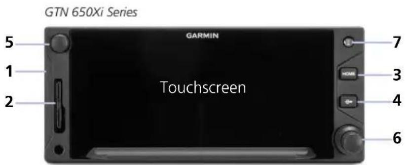
1 Bezel
Ledges provide hand stability when performing data entry and making selections.
2 SD Card Slot
Interface for loading database, exporting log files, and updating software. Compatibility with Flight Stream 510 allows wireless database transfer from the Garmin Pilot app via Database Concierge.
3 Home Key
Provides direct access to the Home page.
4 Direct To Key
Opens the Direct To function for immediate course setting.
5 Volume/Squelch Knob
Allows audio volume adjustment for the active COM radio, NAV receiver, or connected external audio panel. COM squelch and NAV ident functionality accessible via knob push.
6 Inner & Outer Knobs
Multipurpose dual concentric knob allows data entry, list scrolling, map range control, page navigation, and NAV/COM frequency tuning.
7 Photocell
Measures cockpit ambient light level to automatically adjust display brightness for day and night.
Home Key Shortcuts

GTN 650Xi Series: Pushing and holding the Home key provides direct access to Default Navigation features.
GTN 750Xi Series: Pushing and holding the Home key provides direct access to the moving map.
SD Card Slot

NOTE
Do not remove or insert an SD card while in flight. Always verify the system is powered off before inserting or removing an SD card.
FEATURE LIMITATIONS
- SD card in the FAT32 format, with memory capacity between 8 GB and 32 GB
The navigator requires an SD card for the following tasks.
- Exporting data logs
- Enabling Flight Stream connectivity
• Capturing screen images • Updating databases - Upgrading software
INSERT AN SD CARD
When inserting an SD card:
- Verify unit power is off and the slot is empty.
- Hold card such that label faces left edge of display screen.
- Ensure back edge of card is flush with display bezel after insertion.
EJECT AN SD CARD
- Power off the unit.
- Release the spring latch by pressing lightly on exposed edge of card.
For Mac Users
Do not use macOS to format an SD card or the Flight Stream 510 wireless transceiver if you plan to use either as a media storage device for updating databases.
In the event there is a file corruption problem with the SD card (including the wireless transceiver when used as a database storage device), it may be necessary to reformat the card. This can cause an issue when formatting the SD card using macOS, where the newly formatted card will not be recognized by the avionics system. When using a Macintosh computer to format the SD card, or wireless transceiver, Garmin recommends using the SD Memory Card Formatter application available as a download from SDcard.org. When running the application, use the Quick Format option.
Touchscreen
A multi-touch color display provides onscreen controls for unit operation.
Gestures

TAP AND HOLD

Touching the screen briefly with a single finger.
Use this gesture for:
- Opening a page or menu
- Activating a command key or data entry field
- Displaying map feature information
- Selecting an option within an application
Certain momentary controls (e.g., directional arrow keys) provide a secondary tap and hold function.
Tap the key and hold your finger in place until the desired action occurs.
Use this gesture for:
- Scrolling with arrow keys
• Increasing/decreasing values continuously
SWIPE

A smooth motion that involves touching an object, then sliding your finger across the screen and lifting up.
Use this gesture for:
- Accessing multiple panes (right or left swipes)
• Viewing and scrolling lists
• Panning across a map display
FLICK

Swiping the screen in a quick upward or downward motion. Information moves at a fast speed (faster than if holding the arrow key), then slows to a stop.
Use this gesture for scrolling an item list.
PINCH & STRETCH

natural_image
Two hand icons with arrows pointing at circular target zones (no text or symbols)Touch any map with two fingers at the same time, then bring the fingers close together (pinch) or spread them apart (stretch). Just remember: stretch to zoom in and pinch to zoom out.
Use this gesture for magnifying map features.
Keys
COMMON COMMANDS

A flashing icon indicates unread messages.
Open a context menu. Open the system mes

Cancel an active function without inputting data.

Return to the previous page.

Select the corresponding item (e.g., database update). A check mark confirms selection.

Confirm the requested action (e.g., removing a flight plan waypoint)
Move the cursor back a single space at a time.
Input a specified value.
Zoom Control & Scale
Change the current magnification by tapping In or Out.

Directional Keys
Increment or decrement setting values by tapping these directional keys. Tap and hold to increase or decrease the value continuously.
FUNCTION KEYS

Toggle keys turn a specific function on or off. The current state of the function is indicated below the key label.
APP ICONS
Home Page Icons 1







Optional Weather Menu Icons


Tapping one of these icons opens the corresponding application. Some apps provide additional icons for accessing functions on subpages (e.g., System, Utilities).
Additional icons are available when certain optional features are installed and the associated functions are enabled (e.g., Music, Phone, SXM Weather).
Menus
Menus group related controls into an expandable pane, allowing access to multiple functions on a single page. Depending on the number of available functions, a menu may comprise more than one pane.
POP-UP MENUS
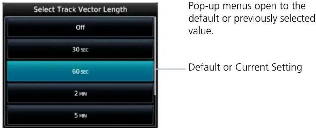
SLIDE OVER MENUS
These menus slide out from the bottom or sides of the display when an object or menu item is selected on the underlying page.

LISTS
Scrollable lists group control keys related to a single function (e.g., selectable range options). Toggle keys either enable or disable list items.

In some cases, Settings or Range keys provide access to selectable setting options.
When scrolling, all keys in the list are inactive.
Tabs
Tabs group information into individual panes. Content includes scrolling lists, data fields, function keys, or a combination of controls.
Tabs are located along the left and right sides of a pane.

Keyboards
The navigator employs multiple keyboard types to serve specific settings and functions.
GTN 750Xi Series
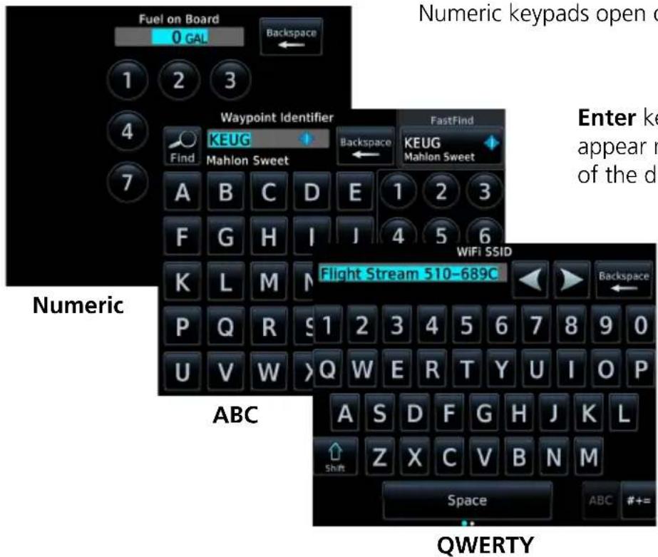
Numeric keypads open on a single pane.
Enter keys always appear near the bottom of the display.
GTN 650Xi SERIES
Alphanumeric keyboards comprise multiple keysets that are accessible by way of swipe or key selection.
ABC keysets, GTN 650Xi Series
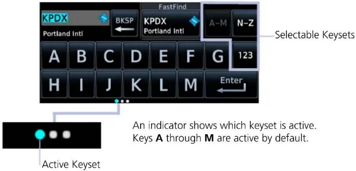
For convenience, GTN 650Xi Series navigators provide a slider, allowing you to quickly select a group of five keys at any given time.
Slider, GTN 650Xi Series

Swiping the key selector left or right scrolls through all available keys.
Active Selection
Key Selector
Alphanumeric keyboards are customizable. You may select a keyboard type from the System Setup app. For more about this option, read Keyboard Type in section 2.
Control Knobs

Dual Concentric Knob
Inner and outer control knobs offer an alternative method for selecting and modifying data without the use of touch keys.

natural_image
Close-up of a black mechanical knob or knob component (no visible text or symbols)Volume/Squelch Knob
A single volume knob controls audio volume for the selected COM radio, NAV receiver, and/or external audio input devices (e.g., remote audio panel).
Depending on configuration, pushing these knobs momentarily performs additional XPDR, COM, and/or NAV related functions.
VOLUME/SQUELCH KNOB FUNCTIONS
| Knob Turn | Adjusting COM radio volume1Adjusting NAV radio volume2 |
| Knob Push | Disabling the COM automatic squelch function1Enabling/disabling the ident tone for the NAV radio2 |
DUAL CONCENTRIC KNOB FUNCTIONS
| Outer Knob Turn | Moving cursor forward or backward within data fieldSelecting a page shortcutTuning major frequency digits^1 |
| Inner Knob Turn | Modifying individual characters in data entry fieldScrolling listsTuning minor frequency digits^1 Zooming map displays |
| Knob Push | Entering current or specified numerical valueToggling between radio and page navigation functions^1 Initiating active/standby frequency flip-flop^1 |
^1 GTN 635Xi/GTN 650Xi/GTN 750Xi only. ^2 GTN 650Xi/GTN 750Xi only.
Page Navigation Labels
A locater bar works in conjunction with the outer control knob, providing quick access to the indicated page. Selectable page options are dependent upon configuration.
Locator More Page Options

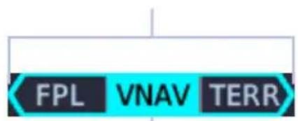
Shortcut Labels Active Page
Turning the outer knob clockwise or counter-clockwise moves the locater through available page options.
A cyan background and border indicate active page and knob focus. Directional arrows show when more options are available.
GTN Xi series navigators allow you to customize up to seven slots on the locater bar.
First and last slots are dedicated page shortcuts. Depending on unit type, slot 1 may open Map ^1 or Default Navigation features ^2 . Slot 9, the last slot, opens the Nearest Airport menu.
^1 GTN 750Xi Series only.
^2 GTN 650Xi Series only.
For more about customizable page slots, read Page Shortcuts in section 2.
Knob Function Indicators
Icons to the right of the bar indicate available knob functions. Indications include, but are not limited to:
Map Active Flight Plan Active

Available functions:
- Map zoom
- Set knob focus to COM standby frequency

Available functions:
• Flight plan scrolling
- Set knob focus to COM standby frequency
Home Page Active

Available functions:
• Multiple pane scrolling (GTN 650Xi Series only)
- Set knob focus to COM standby frequency
Dual Concentric Knob Shortcuts GTN 650Xi/750Xi

natural_image
Close-up of a black mechanical knob or knob component (no text or symbols visible)For convenience, a three-way toggle function allows you to access radio controls quickly via knob push. A cyan border indicates changes in knob focus. This shortcut is useful when transitioning through the different control modes.
Customization options allow you to set knob functionality according to preference. By default:
- Pushing once enables standby COM frequency tuning.
- Pushing twice enables standby NAV frequency tuning.
- Pushing again returns to page navigation mode.
On some dual GTN Xi installations, more complex knob functions allow you to tune radio frequencies on both units from a single navigator. For more about the remote radio control feature, read Remote Radio Control in section 2.
When GTN is not in page navigation mode, the available dual concentric knob functions annunciate at the bottom of the display.
COM Standby Frequency Active
Com Freq / Psh Nav
Available functions:
- Set knob focus to NAV standby frequency
• Frequency tuning
Waypoint Identifier Keypad Active
Wpt Ident / Psh Enter
Available functions:
• Waypoint identifier entry
Numeric Keypad Active
Num Entry / Psh Enter
Available functions:
- Numeric data entry
Direct To Window Active
Edit Wpt / Psh Activate
Available functions:
• Direct-to waypoint editing
• Activate direct-to course
Dual concentric knob control is set to Page Navigation by default. You may change this setting so that COM standby frequency control is the default knob function. For steps, read Revert Knob Function to Radio Control in section 2.
Screen Captures
FEATURE REQUIREMENTS
- SD card in the FAT32 format, with memory capacity between 8 GB and 32 GB
Save images to an SD card at any time using a screen capture.
- Verify unit power is off and the card slot is empty.
- Insert an SD card into the slot.
- Power on the unit and go to the page of interest.
- Push and hold the control knob.
- With the knob depressed, push and release the Home key.
A camera icon momentarily shows in the annunciator bar indicating whether or not the screen capture is successful.

Screen Capture Successful
Image automatically saves to the print folder in the SD card root directory.
To view saved images, remove the SD card and open the print folder on a computer.

Screen Capture Failed
Failures can occur if the SD card is:
Full
• Not present or fully seated
• Corrupt and needs reformatting
- Damaged
Color Conventions

Red
- Warning conditions

Yellow
- Cautionary conditions

Green
- Safe operating conditions
- Engaged modes
• Active COM frequency

White
- Scales and markings
• Current data and values

Magenta
- GPS data
• Active flight plan legs

Cyan
- Pilot-selectable references
• Glide range and best glide airport indications - Standby frequencies

Gray
- Missing or expired data
• Product unavailable

Blue
Water
Compatible Equipment
Line Replaceable Units
| OPTIONAL LRUs |
| ADC |
| AHRS |
| Autopilot |
| DME |
| Flight Stream 210/510 |
| G3X Touch |
| G5 |
| G500/G600 |
| G500(H)/G600/G700 TXi |
| GAD 42 Adapter |
| GDL 69/69A SiriusXM Datalink |
| GDL 88/GTX 345 ADS-B Transceiver |
| GI 275 |
| GMA 35/350 |
| GMX 200 |
| GSR 56 Satellite Datalink |
| GTX Transponders |
| MX20 |
| Radar Altimeter |
| Remote GTN |
| Stormscope |
| TAS/TCAS |
OPTIONAL INTERFACES
| TCAS II |
| Airborne Weather Radar(GTN 750Xi Series only) |
The system consists of multiple LRUs, which are installed behind the instrument panel or in a separate avionics bay. Their modular design aids system maintenance and unit replacement.
Optional LRUs may include compatible equipment from either Garmin or a third party manufacturer. These vary by unit and installation type (VFR or IFR).
Some LRUs provide features that require registration and/or enablement prior to activation.
Compatible LRUs are not limited to the devices shown here.
2 Get Started
POWER UP 2-2
DATABASES....2-7
CONNECTIVITY....2-22
COM....2-26
NAV 2-46
AUDIO PANEL 2-49
XPDR 2-59
ADS-B ALTITUDE REPORTING....2-65
PILOT SETTINGS....2-68
STATUS INDICATIONS 2-85
LOGS 2-96
Power Up
The unit receives power directly from the aircraft's electrical system. Upon power-up, the bezel key backlight momentarily illuminates. System failure annunciations typically disappear within the first 30 seconds after power-up.

The start-up page presents the unit software versions and the name and status of all installed databases.
From here you may:
• View available databases: Tap Databases.
- Advance to the next page: Tap Continue.
For more about the Database Updates page, read Manual Updates in the Databases section.
WI-FI SETUP ACCESS
If a Flight Stream 510 wireless datacard is present, the WiFi Info key appears in the control bar. Tapping this key opens a setup page. Read Wi-Fi Setup for instructions.
FUEL SETUP ACCESS

Fuel settings may be accessible from the start-up page depending on configuration.
If databases require attention (e.g., an expired or mismatched database exists), the Fuel Setup key appears in the control bar. Tapping this key opens a menu of fuel setup options. Read Preset Fuel Quantities for instructions.
Remote Database Confirmation
FEATURE REQUIREMENTS
• GTN Xi software v20.20 or later
• Second GTN Xi series navigator and/or GDU TXi ^1
- SD cards containing databases must be removed from the second GTN Xi series navigator and/or GDU TXi unit(s)
FEATURE LIMITATIONS
• Available for dual GTN Xi and GTN Xi/GDU TXi installations only
Start-up Page, Primary GTN Xi

Confirm database information for all configured GTN Xi and/or GDU TXi units from the start-up page of the primary GTN Xi.
A message informs when databases are up to date. Note the date that the next database is set to expire.
A check mark means that no databases require attention.
Access keys allow you to view database information for all configured GTN Xi and GDU TXi units in the system.
• View the available database updates for each unit: Tap Database Updates.
• View a list of databases for each configured unit: Tap View All Databases.
- Advance to the next page: Tap Continue.
Upon power up, database information for each configured GTN Xi and GDU TXi in the system is sent to the primary GTN Xi for pilot acknowledgment. All other configured LRUs automatically skip the database start-up page once it is determined that no database issues exist.
If the database of a configured LRU is corrupt or missing, the unit will display its database list and indicate the database in question. Confirmation via the primary GTN Xi will still occur for all other configured units if their databases are present and not corrupt.
If an SD card containing databases is installed in the LRU, remote database confirmation will not be available for that unit.
Read more about database conflicts and effective cycles in the Databases section.
Preset Fuel Quantities

CAUTION
Ensure that estimated fuel quantity values are accurate before flight.
FEATURE LIMITATIONS
For the operating limitations of a specific aircraft, consult the POH.

GTN Xi stores preset fuel amounts for estimated full and tab amounts. These settings may not be editable if the unit is interfaced with a digital fuel computer.
Fuel setup keys reside on the start-up page or the Instrument Panel Self-Test page depending on unit configuration.


Fuel on Board
Specify the current fuel quantity.
Tapping this key opens a keypad. Preset keys for "full" and "tabs" aid in fuel data entry.
Initial value automatically reduces based on current fuel flow.
Fuel Flow
Set fuel flow amount.
Tapping this key opens a keypad.
FUEL CAPACITY ENTRY KEYS

Set Full/Tabs
Opens the Fuel Capacity Setup menu.
Select the appropriate data entry key and enter the estimated fuel amounts.
Fuel Full Capacity: Specify the tank full amount.
Fuel Tab Capacity: Specify the tank tab amount.
These values vary according to aircraft type.

Full
Sets the fuel remaining value to the specified full amount.

Tabs
Sets the fuel remaining value to the specified tab amount.
FUEL CAPACITY UNITS

Fuel capacity units are set in the System Units app.
From the Home page:
Tap System > Units > Fuel, and select the preferred units.
Instrument Panel Self-Test
FEATURE LIMITATIONS
• Self-test page availability dependent upon dealer configuration
To ensure safe operation, continuous built-in test features exercise the unit's processor, memory, external inputs, and outputs.

If configured, the results of all external equipment checks performed by the unit display on the Instrument Panel Self-Test page.
Review this list to ensure that all CDI/HSI outputs and other displayed data are correct for the connected equipment.
Tapping Continue advances to the next page.
If an instrument remains flagged after one minute, check the status of the associated LRU, then contact a Garmin dealer for support.
Databases

NOTE
The navigator supports SD cards in the FAT32 format only, with capacities ranging between 8 GB and 32 GB.
Databases are stored in the unit's internal memory. To view update cycles, or to purchase individual databases or database packages, go to flyGarmin.com.
There are two methods for loading and updating databases. Do not attempt either of these while in flight (on ground only).
- Load databases via SD card. Once loading completes, you may power off the unit and remove the card.
- Transfer databases from a Flight Stream 510 wireless datacard. This method requires the Garmin Pilot app on a portable electronic device.
| SUPPORTED DATABASES | |
| Basemap | Bodies of water, geopolitical boundary, and road information |
| ChartView1 | Jeppesen terminal procedures |
| FliteCharts AeroNav terminal procedures | |
| Navigation | Airport, NAVAID, waypoint, and airspace information (Garmin or Jeppesen) |
| Obstacles Obstacle and wire data | |
| SafeTaxi Airport surface diagrams | |
| Terrain Terrain elevation data | |
^1 Optional third-party database.
Aviation Database Errors
Visit flyGarmin.com to report any discrepancies in database information. These may include incorrect procedures, inaccurate depictions of terrain, obstacles and fixes, or errors with any other screen element used for navigation or communication purposes.
For information regarding third-party navigation databases, go to jeppesen.com.
Database Effective Cycles
Most databases expire at regular intervals. Exceptions include Basemap and Terrain, which neither expire nor update on a regular schedule.


The start-up page lists all currently installed databases. Review this list for current database types, cycle numbers, and expiration dates.
Yellow text denotes when a database is:
- Not available
• Installed before its effective date
• Missing date information
• Past its expiration date
DATABASE EFFECTIVE STATUS
Databases with no effective date
Databases with specified effective dates
• Effective upon release
• Includes Basemap and Terrain
• Effective during a specific period
- Unit determines database status using the current date and time from GPS
• Automatic activation occurs on the effective date
Overwriting SD card database files
When database files are loaded to the SD card, any previously loaded database files of the same type residing on the card are overwritten. This includes loading a database of a different coverage area or data cycle than that currently residing on the SD card.
Database Conflicts
FEATURE LIMITATIONS
• Applicable to dual GTN Xi and GTN Xi/GDU TXi ^1 installations only
Conflicts occur when the database of a configured GTN Xi or GDU TXi is corrupt, missing, or past its expiration date.
When this happens:
- A caution indication appears on the start-up page of the primary GTN Xi. Depending on the type of conflict, a selectable information key may appear next to the database name.
- The database list displays on the appropriate LRU (remote confirmation is no longer available for that unit).
- The database name appears in yellow on both the primary GTN Xi and the associated LRU.
Resolve database conflicts when they occur.
DATABASE MISMATCH


Tapping Database Mismatch displays all databases of that particular type and their associated LRUs. Expired or corrupt databases appear in yellow at the top of the list.
MISSING DATABASE INFORMATION
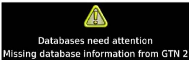
A message informs when database information from the indicated LRU is missing. This appears when an LRU is not powered on during start-up.
Always verify that all LRUs are online before tapping Continue.
Active and Standby Databases
The navigator uses two types of databases:
Active Databases Standby Databases
The databases in use by the system. Databases that have not reached the effective date. These remain on the SD card until they become effective.
Database Info
WHERE TO FIND IT

flowchart
graph TD
    A["Home"] --> B["System"]
    B --> C["System Status"]
During normal operation, you can view information about all active and standby databases from the System Status page.
ACTIVE DATABASE LIST
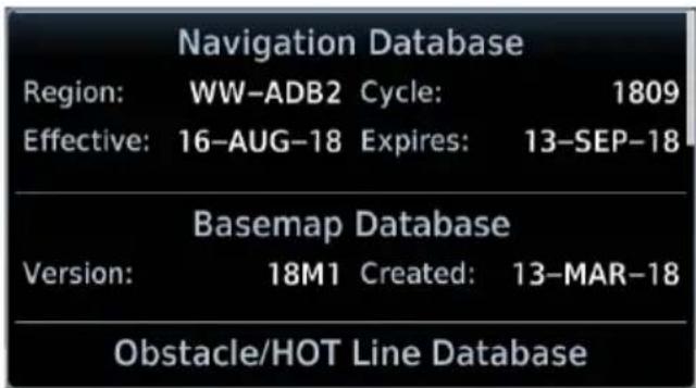
Selecting Active displays information about the databases currently in use. You can also access copyright information from here.

Tapping View Copyrights displays copyright information for all installed databases.
STANDBY DATABASE LIST
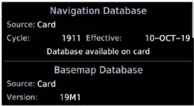
Selecting Standby displays information about databases that are not yet effective.

GTN Xi notifies when no standby databases are available.
DATABASE NOT FOUND

Notifications for databases not present or available also display in the form of system messages.
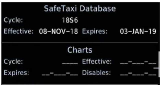
Review the Active Database Info list to determine the status of the indicated database.
Database Not Present
Manual Updates
FEATURE LIMITATIONS
The Database Updates page is available only when:
• The aircraft is on ground
• The start-up page is active (i.e., during power up)
Database Updates Page, GTN 750Xi
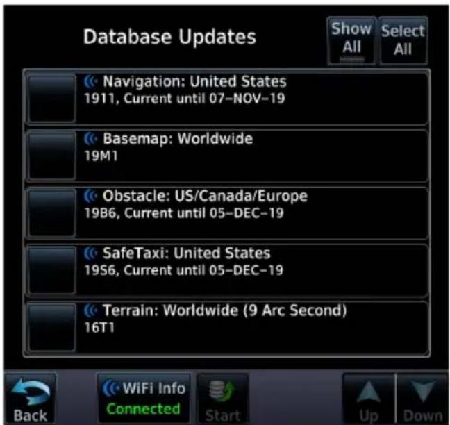
The Database Updates page presents a list of all available databases.
To open, tap the Databases key on the start-up page.

DATABASE SOURCE INDICATION

A Connext icon indicates when a database is from Garmin Pilot via wireless transfer. No indication means the database is either from an SD card or the unit's internal standby queue.
SELECT ALL DATABASES

Select individual databases for transfer, or choose Select All if all listed databases require updating.

By default, this page displays only the databases recommended for update.
A message notifies when no such databases are available.
No recommended databases available. Press Show All button to see exhaustive list.

After all selections are made, initiate the update process by tapping Start.
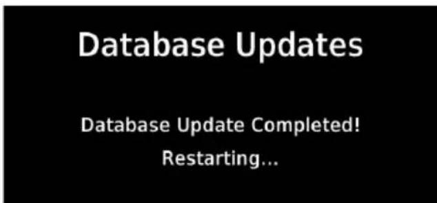
The unit automatically restarts once all updates are complete.
Dual GTN Xi and GTN Xi/GDU TXi Installations ^1
To allow remote database confirmation from the primary GTN Xi series navigator, remove the SD card from the second GTN Xi series navigator and/or GDU TXi unit after installing databases.
^1 Applicable only to GTN Xi series navigators with software 20.20 or later and GDU TXi units with software v3.30 or later.
SHOW ALL DATABASES

Tapping Show All displays a complete list of all databases.

This list may include databases that are:
- Not yet effective
- Older than the currently active database(s)
- Unable to update due to an error
ERROR INFORMATION

To determine the cause of a database error, tap Error Info.

An information window provides details regarding the state of the database.
SELECT REGION

This key appears when two databases are of the same type and cycle, but pertain to different regions.

To specify a database region:
Tap Select Region, then select the appropriate menu option.

Automatic Updates
Automatic updates occur when:
- A newer database is detected on the SD card or in the internal standby queue
• A newer database is within its effective dates
• The aircraft is on ground
When a newer database is available, follow the on-screen prompts to complete the update process.
INSTALL OR UPDATE A DATABASE USING AN SD CARD

- Download a database onto an SD card.
- Insert the SD card with the most recent database(s) into the card slot.
- Power on the unit.

Selecting Update opens the Database Updates page, where a list of the newest databases is available for review.

Select the databases for transfer, then tap Start.

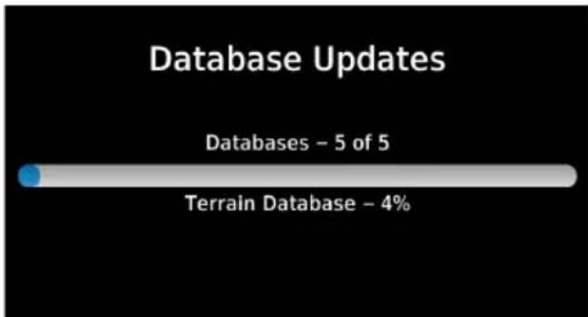
bar
Database Updates | Category | Value | |---|---| | Databases | 5 of 5 | | Terrain Database | 4% |All newer databases (effective and expired) transfer from the SD card to the internal standby queue.
A progress bar displays the name of each database as it uploads to the unit.
Terrain databases may require up to 5 minutes for transfer. Total transfer time depends on the SD card type.
The unit automatically restarts once the update is complete. Updates are indicated in the list of currently installed databases.
Database Concierge
FEATURE REQUIREMENTS
• Flight Stream 510 wireless datacard
• Garmin Pilot app on a mobile device
• The aircraft is on ground

Database Concierge allows wireless transfer of databases from a mobile device while the aircraft is on ground.
A pilot selects and downloads databases inside the Garmin Pilot app. Transfers occur once Flight Stream 510 establishes a wireless connection inside the aircraft.
Database Concierge Transfer Function
- Provides automatic updates for databases with effective dates
- Preloads databases that are not yet effective by placing them in the internal standby queue
• Displays database type, cycle, effective date, and transfer progress - Allows manual operation via Start key
- Requires pilot confirmation
TRANSFER A DATABASE USING DATABASE CONCIERGE

- Purchase database(s) from flyGarmin.com.
- Open Garmin Pilot and follow the download instructions.
- Install Flight Stream 510 and then power on unit.
- Connect to Wi-Fi.
- Follow the on-screen prompts.

Database Concierge transfers databases from the app to Flight Stream 510. A progress bar shows when this process is complete.
GTN Xi either updates or preloads databases based on their effective date. A second progress bar indicates upload status.
The unit automatically restarts upon database activation.
SKIP TRANSFER
Tapping Skip Transfer and Continue cancels any unfinished wireless transfers and initiates the update process.
The unit activates any databases that completed transfer before the interruption. Previously selected databases on an SD card or in the internal standby update as well. The message “Transfers interrupted” displays if no databases are available.
Database SYNC

Database SYNC minimizes database maintenance by synchronizing active and standby databases across all configured LRUs. Once a standby database becomes effective, each LRU automatically generates an update prompt.
FEATURE LIMITATIONS
• Not applicable to Terrain database
WHERE TO FIND IT

flowchart
graph TD
    A["System"] --> B["System Status"]
    B --> C["Menu"]
This function resides in the System Status menu.
Home > System > System Status > Menu > Database SYNC

A pop-up informs you that enabling Database SYNC may overwrite any databases currently in standby.
Toggling Database SYNC off disables the Chart Streaming function (if enabled).
Database SYNC Transfer Function
- Enables automatic database synchronization across all capable Garmin avionics
• Includes active and standby databases - Prompts unit restart if a new database is effective and the aircraft is ground
Dual GTN Xi Installations
To prevent crossfill errors after installing new databases, be sure to install matching databases on both GTN Xi units and allow Database SYNC to complete before departure.
Chart Streaming

Chart Streaming allows streaming of individual charts on an as-needed basis until database sync is complete.
Toggling this function off has no affect on Database SYNC.
FEATURE LIMITATIONS
• Available only when Database Sync is active and a current chart database is available
WHERE TO FIND IT
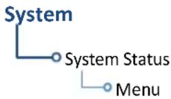
This function resides in the System Status menu.
Home > System > System Status > Menu > Database SYNC > Chart Streaming
Chart Streaming Function
- Enables automatic streaming of individual charts from the newest chart database
• LRUs with chart streaming enabled display the most current chart information - Current charts display on the Charts page; chart overlays are available for display on Map
• Chart database effective date displays on Charts page when chart expires
• Available for both ChartView and FliteCharts
A typical chart database may take up to one hour to synchronize across multiple LRUs.
Connectivity

Connext works via the Bluetooth data link to provide up-to-date, wireless information throughout the cockpit.
FEATURE LIMITATIONS
- Unit allows pairing of up to 13 Bluetooth enabled devices, with two simultaneous device connections
• Auto reconnect function is not available for Android devices
Connext Setup
WHERE TO FIND IT
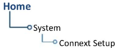
flowchart
graph TD
    A["Home"] --> B["System"]
    B --> C["Connext Setup"]
The Connext interface allows communication with Garmin Pilot from a portable electronic device.
Connext Features
The following features are available on your portable electronic device.
• GPS position and velocity information
• Uncorrected barometric pressure altitude used by transponder and ADS-B
• ADS-B In traffic data
• FIS-B weather and flight information
• AHRS data from built-in sensor ^1, 2, 3
^1 Attitude data does not output to other installed avionics. ^2 Flight Stream 210 only. ^3 The internal AHRS sensor is only for use with a portable electronic device. All internal AHRS functions are automatic and do not require pilot action.
Bluetooth Setup
Bluetooth Wireless Features
- FIS-B weather
- ADS-B traffic
• GPS/WAAS position, velocity, and time - Pressure altitude
AHRS - Magnetic heading
• Flight plan transfer - Flight data logs
• GSR 56 SMS messaging - SXM weather
The unit supports wireless pairing with up to 13 portable electronic devices via the Garmin Pilot app.
Bluetooth device management options reside on the Paired Devices page. Opening this page automatically initiates device pairing.

Device information and pairing mode status display on the Connext Setup page.
Controls for enabling Flight Stream features are reside here. These include:
- Flight Plan Import
- Databases
- Phone/SMS
BLUETOOTH NAME
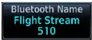
This key allows you to enter the name of the Bluetooth enabled device. Use the keypad or control knobs to enter the device name.
Managing Paired Devices

To view a list of all paired devices and their connection status, tap Manage Paired Devices.
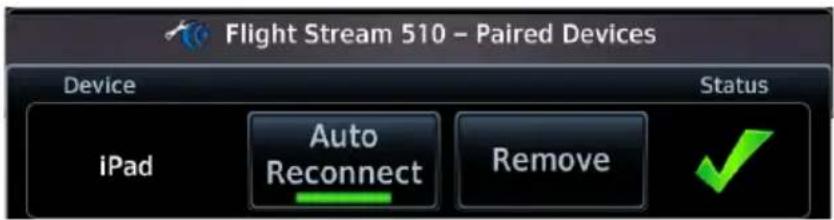
To enable automatic connection between the unit and a paired device at power up, tap Auto Reconnect.
AUTO RECONNECT
Enables automatic connection between the unit and the paired device when the two are within range.
REMOVE
Removing a device from the list means it is no longer paired with the unit. This action requires pilot confirmation.
Be sure to remove pairing on both devices before attempting to pair them again.
CONNECTION STATUS

The device is configured and communicating properly.

The device is not available and is not configured or it is not communicating properly.
Importing a Flight Plan

Allow automatic import of flight plans via Bluetooth wireless technology.
Once the transfer is complete, an advisory message informs that a new flight plan is available for preview.
To view the flight plan, acknowledge the advisory and tap Preview.
It may be necessary to turn this function off if a portable device application makes repeated erroneous attempts to send flight plans to the unit.
Wi-Fi Setup

Tapping WiFi Info opens an information page. This feature is accessible from the Database Update and start-up pages.

Information includes:
• Database Concierge connection status
- Connected device name
- Database update availability and instructions
• Wi-Fi SSID and password
When setting up Wi-Fi, use a password that contains letters in mixed case and numbers.
WI-FI INFO KEY STATUS ANNUNCIATIONS
Wi-Fi connection status annunciates on the key label when the information page is not active.

Flight Stream 510 requires power up.

Wi-Fi is active, but the unit is waiting to connect with a device.

Connection complete. Flight Stream 510 requires Garmin Pilot to be opened in order for database transfer to commence.

Garmin Pilot opened and streaming to unit.
CONNECT TO WI-FI
Follow the onscreen prompts when connecting to the Wi-Fi network.
- Install Flight Stream 510 and then power on unit. Observe Wi-Fi status changes from "Offline" to "Ready."
- Tap WiFi Info.
- Enter the required SSID and password using the provided keypads.
- Enable Wi-Fi setting on the portable device. Wi-Fi status changes to "Open App" once pairing is complete.
COM
AVAILABLE WITH: GTN 635Xi/650Xi/750Xi
COM Standby Control Panel
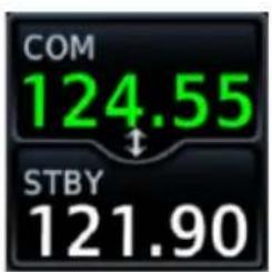
VHF COM transceiver controls are accessible via the selectable standby (STBY) frequency window.

| 1 Frequency Entry Field 4 Transfer (Flip-Flop) Key | |
| 2 Find Key 5 Data Entry Keys | |
| 3 Monitor Key | |
From the COM Standby control panel you can:
• Specify a standby frequency
- Swap active and standby frequency values
- Enable monitor mode
• Access radio volume controls
COM Volume Controls

pie
| Category | Percentage (%) | | :--- | :--- | | COM | 43 | | VOL | | | STBY | 121.90 |Adjust radio volume with the small knob according to your preference. The unit retains volume settings over power cycles.
Open Squelch

Push the volume/squelch knob to override the automatic squelch function. Push it again to return the squelch to automatic operation.
"SQ" annunciates in the COM active frequency window to show when the squelch is overridden (i.e., when the squelch is open).
The automatic squelch function rejects many localized noise sources. Overriding this function may be helpful when listening to a distant station or setting the volume level.
Volume/Squelch Knob Adjustments

natural_image
Close-up of a black mechanical knob or knob component (no text or symbols visible)Knob focus is determined by radio selection. Selecting the COM control sets the focus to the COM radio. Selecting the NAV control sets it to the NAV radio.
When COM radio is active:
- Pushing the knob disables automatic squelch control.
• Turning the knob adjusts the COM volume percentage.
If NAV radio is active:
- Pushing this knob enables or disables the ident tone.
• Turning the knob adjusts the NAV volume percentage.
COM Radio Setup
WHERE TO FIND IT
COM radio customization options are accessible via the System Setup app.

flowchart
graph TD
    A["System"] --> B["System Setup"]
    B --> C["COM/NAV"]

1 COM Channel Spacing Key 4 Knob Control Radios Key
1
2 Knob Control Default Key 5 COM Sidetone Controls
3 Reverse Frequency Lookup Key

flowchart
graph TD
    A["COM / NAV"] --> B["Channel Spacing"]
    A --> C["Reverse Frequency Lookup"]
    A --> D["Knob Control Default"]
    A --> E["Knob Control Radios¹"]
    A --> F["COM Sidetone Volume"]
    B --> G["8.33 kHz\n25 kHz"]
    D --> H["Page Navigation\nCOM Radio"]
    E --> I["Local\nLocal & Remote"]
    F --> J["Link to COM VOL\nSet offset value"]
^1 Dual GTN Xi installations only.
From here you can:
- Set transceiver channel spacing
- Enable reverse frequency look-up functionality
- Select the default knob control function
- Enable remote radio frequency tuning ^1
- Adjust sidetone volume offset
Set COM Channel Spacing
The unit supports channel tuning for both 8.33 kHz and 25 kHz channels within radio-frequency range. Channel spacing is set to 25.0 kHz by default.

Tapping COM Channel Spacing toggles the transceiver channel spacing between 8.33 kHz and 25.0 kHz.
8.33 kHz 25.0 kHz

other
| Category | Value | |---|---| | COM | 124.555 | | STBY | 119.105 |8.33 kHz step configuration is available for European operations.
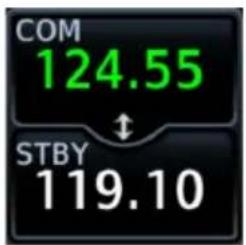
COM radio operates in the aviation voice band, between 118.000 and 136.975 MHz, in 25.0 kHz steps.
If flying in a region where 8.33 kHz channel spacing is available, set the COM radio to 8.33 kHz to prevent the loss of any stored or recently used frequencies.
Revert Knob Function to Radio Control
You may change the default function of the dual concentric knob to accommodate your workflow. Knob control is set to Page Navigation by default.

Tapping Knob Control Default changes the default setting to COM Radio for standby frequency control. Page navigation remains accessible via knob push.
From the Home page:
Tap > System > Setup > COM/NAV > Knob Control Default.
Default knob function indicators change based on selection.
Page Navigation COM Radio


Tapping the key again returns the default setting to Page Navigation.
Access Remote Unit Radio Functions
FEATURE LIMITATIONS
• Knob Control Radios option available for dual GTN Xi installations only
Remote radio frequency tuning is available for dual GTN Xi installations. The Knob Control Radios option allows you to access remote unit radio functions via the dual concentric control knob.

Tapping Knob Control Radios toggles the knob function between two control options.
Local
Limits knob functionality to local unit radios and page navigation only.
Local & Remote
Sets knob control to both local and remote navigators.
For information about remote unit radio functions, read Remote Radio Control in this section.
Enable Reverse Frequency Look-up
FEATURE REQUIREMENTS
- Valid position data
• Active navigation database
FEATURE LIMITATIONS
• Available only for the nearest stations in the database

Enabling this option displays the facility identifier and frequency type for active and standby frequencies.
The unit verifies the displayed frequency against the database at least once per minute.

When frequency look-up is active, COM displays:
- Nearest facility identifier (if available)
• Multiple facility indication (if more than one) - Frequency type
- Approach or Departure indications (if applicable)
When flying between airports that use the same frequency, it may take up to 2 minutes for look-up information to change after crossing the half way point.
Adjust Sidetone Volume Offset
FEATURE LIMITATIONS
• Availability dependent upon configuration
- Offset range: +/-25% of total COM audio volume range

If the unit is wired for audio output, set the sidetone volume offset to the preferred level. By default, the offset value is set to zero percent.
The unit retains manual offset settings over power cycles.
COM sidetone is audio spoken into the microphone that is played back in real time over the headset. The offset setting determines sidetone volume for the COM during radio transmission. Adjustments determine the amount that the sidetone volume level is offset from the COM receiver volume or the configured sidetone volume.
LINK TO COM VOLUME
Enabling this function allows you to adjust the amount that the sidetone volume level is offset from the COM receiver volume. These adjustments are dynamic in that they vary with the COM receiver volume level.
To adjust the offset from the COM receiver volume:
- Enable Link to COM VOL.
- Tap Offset and adjust as necessary.
To adjust the offset from the configured sidetone volume, disable Link to COM VOL and then adjust the offset as necessary. These adjustments are fixed as they are relative to the configured sidetone volume.
Tuning & Monitoring

Communication frequencies are split between two selectable windows.
The upper window presents the active COM radio frequency. This is the frequency currently in use for transmit and receive operations.
The lower window presents the standby radio frequency. This frequency may be set and activated at any time.
COM STATUS INDICATIONS
Status annunciations denote active functions, modes, and frequency types.


Transmitting

Receiving transmission

Monitor mode active

Automatic squelch is overridden (i.e., squelch is open)
Active radio ID ^1
KSLE TWR
Reverse frequency information (sample text)
Direct Tuning

You may enter a standby frequency using the data entry keys on the COM Standby control panel or by turning the control knob.
Tapping STBY opens the control panel. From here you may specify a frequency or select one using the provided search options.
The current standby frequency value displays in the direct tuning field.
DATA ENTRY KEYS
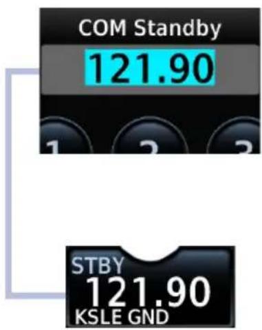
Enter a new standby frequency using the provided data entry keys or by turning and pushing the control knob.
To cancel the entry and exit the control panel, tap Back.
Entering the new frequency value places it in standby.
FREQUENCY AUTOFILL

Numeric characters autofill the first valid frequency value based on each selected digit.
Autofill characters are muted and display from the cursor position to the right of the field.

Selecting a digit that is not valid for the cursor location results in no entry.

Attempting to enter a frequency value after selecting an invalid digit generates a pop-up message.
Confirm the request by selecting OK.
Simplified Frequency Entry
The direct tuning field allows you the option of entering frequencies without typing the leading and/or trailing digits. For example: To enter frequency 121.50, you need only tap 2, 1, and 5. The field autofills the leading "1" and trailing "0."
KNOB TUNING
The dual concentric control knob allows you to enter a standby frequency without opening the control panel. Pushing the knob toggles between radio and page navigation functions.
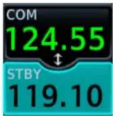
The selected STBY window turns cyan when the knob is used to change the STBY frequency.

If no action occurs, the selected STBY window reverts to cyan text after 3 seconds. This indicates it can be controlled by the knob.

When the STBY COM frequency is no longer selected, it reverts to white text.
Transfer Frequency to Active (Flip-Flop)
Before The transfer (or f Afterp) function

other
| Category | Value | |---|---| | COM | 124.55 | | STBY | 119.10 | | COM | 119.10 | | STBY | 124.55 |allows you to swap the active and standby frequency values.
This function is accessible multiple ways.
ACTIVE FREQUENCY WINDOW
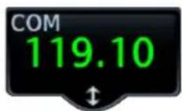
Tapping this window swaps the active frequency value with the standby frequency displayed in the lower window.

Tap once to swap the displayed frequency values. Tap again to swap them back.
A transfer icon indicates that flip-flop functionality is available.
XFER KEY

Tapping this key on the COM Standby control panel performs the same function as tapping the COM active frequency window.
Frequency Flip-Flop via Control Knob

natural_image
Close-up of a black mechanical knob or knob component (no text or symbols visible)Pushing and holding the control knob for 0.5 seconds automatically flip-flops the active and standby frequency values.
- "Hold for flip-flop" control label appears in the annunciator bar
• Standby and active COM frequency values swap
Hold for Flip-Flop
Frequency Autofill & Transfer
If you initiate a transfer before completing frequency entry, the direct tuning field autofills the remaining characters, enters the frequency into the standby field, then swaps it with the active frequency.
Remote Radio Control
FEATURE REQUIREMENTS
• Second GTN Xi series navigator: GTN 635Xi, GTN 650Xi, or GTN 750Xi
FEATURE LIMITATIONS
• Dual GTN Xi installations only
• NAV radio options available only on GTN 650Xi/750Xi
Some dual GTN Xi installations allow you to tune radio frequencies on both units from a single navigator. Control options allow you to switch between local control (local navigator only) and remote control (local and remote navigators).

An inverted radio label differentiates COM/NAV 2 from COM/NAV 1.
This label always appears for COM/NAV 2 regardless of whether it is the remote or local radio.

Tapping STBY opens the control panel for the indicated radio.
From here you may tune the indicated radio or access controls for all radios by tapping the Radios key.

Radios are listed according to navigator (local/remote). Cyan denotes the current radio selection. A frequency control key allows you to open the standby control panel for the associated radio.
Tapping Back closes the list and returns to the previous view.
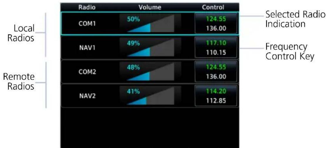
bar
| Radiol Type | Category | Volume (%) | Control | | :--- | :--- | :--- | :--- | | Local Radios | COM1 | 50 | 124.55 | | Local Radios | NAV1 | 49 | 117.10 | | Local Radios | COM2 | 48 | 124.55 | | Local Radios | NAV2 | 41 | 114.20 | Selected Radio Indication; Frequency Control Key; Remote RadiosTurning the volume knob adjusts the volume level for the active radio only.
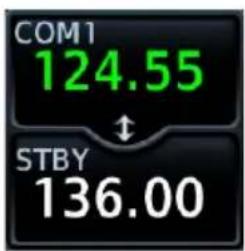

Changes in radio selection and standby frequency are reflected in the control bar.
Remote Radio Control Knob Access

natural_image
Close-up of a black mechanical knob or knob component (no text or symbols visible)When remote radio control is active, you may toggle between multiple radios quickly via knob push. Knob focus indications on the control bar and on the Radios page change to reflect the current radio selection.
Available radio options are dependent upon unit type.
• COM only units switch between COM 1 and COM 2
- Units with COM and NAV radios scroll as follows: local COM > local NAV > remote COM > remote NAV
Direct Tuning from the Radios Page:

Knob tuning adjustments and frequency transfers are reflected in real time on the corresponding control key.
LOAD FREQUENCY OPTIONS

flowchart
graph TD
    A["NAV1"] --> B["Active ↑"]
    C["NAV2"] --> D["Active ↑"]
    E["Standby"] --> F["Standby"]
You can load active or standby frequency values to a COM or NAV radio from a search tab or waypoint information page (i.e., Airport, VOR). Selecting a frequency from one of these locations opens a pop-up.
Select the Active or Standby key for the appropriate radio.
Monitor Mode
Enabling monitor mode allows you to listen to the standby frequency while the unit continues monitoring the active COM channel.
When the COM active frequency receives a signal, the unit automatically switches back to the active frequency. Once activity on the COM active channel ceases, the unit returns to listening to the standby frequency.
Tower Transmission (Active Frequency)
ATIS Broadcast (Standby Frequency)
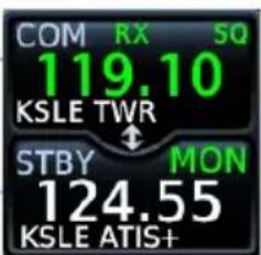
Monitor mode is useful when you want to listen to a recorded broadcast (e.g., ATIS) on the standby channel, but still receive control tower transmissions on the active channel.
Frequency Selection
The unit provides multiple options for finding and selecting a standby frequency from the available database frequencies.
Search Tabs

The Find key provides access to multiple search tabs. Each tab displays a list of selectable identifiers based on specific criteria.
| Nearest Airports | Lists up to 25 airports within a 200 nm radius |
| Nearest FSS & ARTCC | List the distance, bearing, and frequency associated with the specified facility name |
| Recent Lists up to 20 of the most recently tuned frequencies | |
| Flight Plan Lists all frequencies contained in the active flight plan | |
| User Lists up to 15 user-defined frequencies | |
TAB ENTRIES

Each entry includes general information about the associated waypoint.
MULTIPLE FREQUENCIES

Tap Multiple FREQ and select a frequency from associated pop-up.
This key appears when more than one frequency is available at the indicated identifier.
Applicable to functions displaying information only (Nearest Airports, FSS, and ARTCC).
Remote Frequency Selection
FEATURE LIMITATIONS
• Availability dependent upon configuration
On units configured for remote frequency recall, user frequencies are selectable via a remote switch.
- Pressing the switch once loads the next user frequency into the STBY window
- Pressing the switch repeatedly scrolls through the list of presets
- Some installations may have two dedicated recall switches: one to scroll up, one to scroll down
- Selections do not activate until transferred to active
Emergency Frequency
Pressing and holding the volume knob provides a quick method for remotely tuning the emergency frequency (121.50 MHz). This function also sets 121.50 MHz as the active frequency. Remote COM Lock is not activated if using this method. This feature is available any time the unit is on, regardless of GPS or display status.
Remote COM Lock
If configured, pressing and holding the remote COM transfer key for two seconds locks the COM at 121.50 MHz, preventing further changes in frequency. A message informs of the change in status. To unlock, press and hold the remote key again.
If the radio loses communication with the system, the unit automatically tunes to 121.50 MHz for transmit and receive operations, regardless of the displayed frequency.
Create User Frequencies
FEATURE LIMITATIONS
- Names may be up to seven characters in length
• Maximum number of 15 user frequencies
Edit Frequency

flowchart
graph TD
    A["Name"] --> B["Type name"]
    C["Frequency"] --> D["Specify Frequency"]
    E["Save"] --> F["Delete"]
Create or edit user frequencies from the Edit Frequency pop-up menu.
| Name | Assign the frequency a unique identifier. |
| Frequency | Specify a frequency value. |
| Save | Add the frequency to the user frequency list. |
| Delete | Remove the selected user frequency from the list.Appears only for existing entries. |
ADD A USER FREQUENCY
From the COM Standby page:
- Tap Find > Select the User tab.
- Tap Add User Frequency.
- Specify the frequency name and value.
- Tap Enter.

A pop-up message informs when the user frequency list is full.
EDIT USER FREQUENCY

Tapping the Edit key for an existing entry opens the same pop-up. From here you may modify the user frequency name and value.
Tapping Enter stores all changes.

Tapping Delete removes the selected user frequency from the list. A pop-up message requests confirmation.
COM Alert

If the radio fails:
- Red "X" displays over the COM radio control
• Advisory message alerts
• COM control page is not available
COM radio fail annunciations are designed to be immediately recognizable. If a failure occurs while the control page is active, the display automatically returns to the previous page.
For information regarding pilot response to a COM radio failure, consult the AFMS.
Stuck Microphone
The COM transmitter automatically times out after 30 seconds of continuous broadcasting. This may occur when:
- Push-to-talk key on the microphone is stuck or accidentally left in the keyed position
- Push-to-talk function continues to transmit after releasing the key
The advisory message “COM push-to-talk is stuck” alerts for as long as the condition exists.
NAV
AVAILABLE WITH:
GTN 650Xi/750Xi
Frequency Tuning & Selection
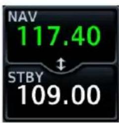
Navigation frequency tuning, transfer, and selection functions are identical to those used for communication frequencies.
Direct Tuning

You may enter a standby NAV frequency using the data entry keys on the NAV Standby control panel or by turning the dual-concentric control knob.
GTN Xi automatically decodes Morse code and displays the Ident for the active frequency above it.
The reverse frequency lookup identifier displays below the frequency value. Frequency lookup results are based on GPS position and database information.
GTN 650Xi SERIES
Due to spatial considerations, only one frequency control may display at a time. COM is the default frequency control option.
STANDBY NAV FREQUENCY ENTRY
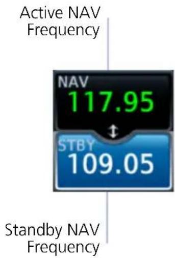
other
| Metric | Value | | ---------------- | ------- | | Active NAV Frequency | 117.95 | | Standby NAV Frequency | 109.05 |To change the standby frequency:
- Push the dual concentric control knob repeatedly until the standby NAV frequency window is activated.
- Rotate the inner and outer knobs or tap STBY and enter the frequency using the data entry keys.
Upon selection, the standby frequency window remains active for approximately 30 seconds.
You can tap XFER to assign the standby value as the active frequency, or select the active NAV frequency window to flip/flop values.
Navigation frequencies include:
- Glideslope
- Localizer
• VOR
Search Tabs

The Find key provides access to multiple search tabs. Each tab displays a list of selectable identifiers based on specific criteria.
IDENT

When the standby NAV frequency window is active, pushing the volume knob activates the NAV IDENT function.
- "ID" annunciates in the active NAV frequency window
- Morse code tones are audible
Volume Knob Adjustments

natural_image
Close-up of a black mechanical knob or knob component (no text or symbols visible)Turning the volume knob while the NAV frequency window is activated adjusts the radio's volume percentage.
NAV Alert
If the radio fails:
- Red "X" displays over the NAV radio control
• Advisory message alerts
• NAV control page is not available
NAV radio fail annunciations are designed to be immediately recognizable. If a failure occurs while the control page is active, the display automatically returns to the previous view.
Use an alternate method of navigation in response to a NAV radio failure.
Audio Panel
AVAILABLE WITH:
GTN 725Xi/750Xi
Audio Panel Controls

Audio panel controls are accessible via the Audio Panel key. This key is unavailable if the unit is not configured for audio or intercom LRUs, such as GMA 35.

PLAYBACK CONTROLS
The voice recorder feature records all audio heard on any MIC selected COM radio selected for transmission. Playback is heard by anyone listening on the selected radios. The clearance recorder can record up to 2.5 minutes of COM audio.
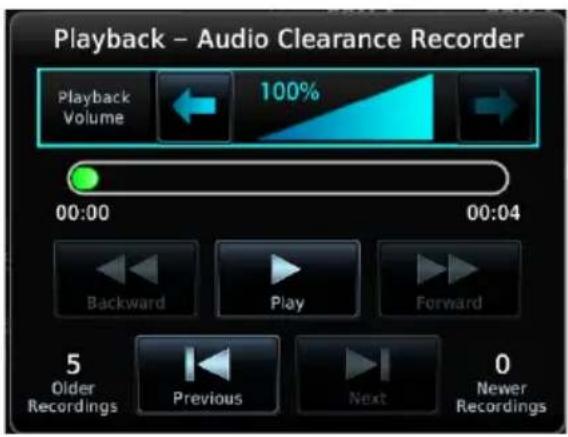
Tap Playback Controls to:
• Set volume level of recordings
- Play, pause, and cycle through recordings
CABIN SPEAKER CONTROL AND VOLUME
When cabin speakers are active, tap Speaker Volume to set the volume level.
HIGH SENSE
Prior to an ILS approach, tap High Sense for high marker sensitivity.
Mic Setup

MIC selection can be set in the MIC window or on the Audio Panel page.
Tap MIC to toggle between MIC 1 and MIC 2.

Under MIC Selection, select which COM you want as your MIC selection. The selected MIC is automatically monitored as indicated by the green numbers in the MON field.
PASSENGER ADDRESS
Tap Passenger Address to toggle the passenger address system on and off.
SPLIT MODE
Active:
- Pilot uses one radio for MIC audio while the copilot uses a different radio
- Pilot and copilot can transmit simultaneously over separate radios
- Pilot can still listen to individually selected radios
- Pilot and co-pilot may talk and listen independently to the radios or PA
- Crew Intercom key is available allowing pilot and co-pilot to talk to each other
Inactive:
- Crew Intercom key is removed
• Selections are limited to Monitored Radios and MIC Selection
3D Audio
When enabled, 3D audio allows you to focus on and understand one source at a time. Depending on the selected COM channel, audio can be heard from your left, in front of you, or from your right.
To hear 3D audio, set stereo/mono headphones to the stereo position.
MARKER Audio
The GMA 35 marker beacon receiver uses an audio indicator to alert you when the aircraft passes over a marker beacon transmitter. When a green bar displays on the MRKR Audio key, the audio from the receiver can be heard on the headsets.
Tap MRKR Volume to set the volume level of the alert.
The GMA 35 marker beacon receiver and indicators are part of the ILS system.
The marker beacon lamps operate independently of any audio selection and cannot be turned off. The GMA 35 can drive external marker lamps if required and also provides an autopilot middle marker sense output.
Marker beacon annunciations alternate between the standard and blinking symbol at the blink interval noted.
| STANDARD SYMBOL | BLINKING SYMBOL | MARKER TYPE | BLINK INTERVAL |
| IM | IM | Inner 250 ms | |
| MM | MM | Middle 333 ms | |
| OM | OM | Outer 750 ms | |
Intercom
AVAILABLE WITH: GTN 725Xi/750Xi
Intercom Modes

Intercom controls are accessible via the Intercom key. There are different modes of operation to control communication, music, and the telephone in the aircraft.

flowchart
graph TD
    A["Pilot VOL/SQ"] <--> B["Co-Pilot VOL/SQ"]
    B --> C["Passenger VOL/SQ"]
    C --> D["Music 1"]
    C --> E["Music 2"]
    C --> F["Telephone"]
    D --> G["Back"]
    E --> H["MSG"]
    F --> I["Menu"]
Tap the arrow between the intercom recipients. When the arrow is green, it indicates communication is active between the recipients.
You can allow the co-pilot to hear what passengers hear.
Tap Menu > Group Co-Pilot with Passenger.
- Split mode is unavailable
• Co-pilot intercom/audio controlled by passenger
This is not recommended for multi-crew aircraft.
Intercom Setup
Setup controls allow you to access:
• Communication modes between pilot, co-pilot, and passenger
• Distribution and mute options for two music interfaces
• Distribution and volume of phone calls
Passengers cannot transmit over the active COM radio, even if equipped with a PTT key.
VOLUME AND SQUELCH ADJUSTMENTS

NOTE
Installations that utilize GMA 35 discretes must have the pilot squelch set to manual and 100% volume to allow installers to configure the GMA 35 discretes.
Volume and squelch may be set separately for the pilot, co-pilot, and passenger intercoms.
To set volume and squelch levels, tap Pilot VOL/SQ, Co-Pilot VOL/SQ, or Passenger VOL/SQ.
Directional keys increase or decrease volume and squelch.
Tapping Auto Squelch allows the unit to set squelch level automatically. Toggle this function off for manual adjustments.
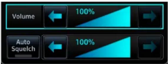
Music Setup
The GMA 35 provides two music interfaces. Select Music 1 or Music 2 to set:
• Who hears music
- When to mute music
- Music volume
At every power cycle, the "Mute music during radio" selection is active.
Telephone Setup

NOTE
When using the GSR 56 Iridium phone system, Garmin recommends activating audio only during phone calls.
The GMA 35 provides a 2-way telephone interface and depends on the state of the telephone distribution. Telephone communication is much like using the intercom, allowing both parties to talk at once.
Tap Telephone to set:
• The recipients of a telephone call
• The volume of the telephone call
Telephone audio distribution is retained across power cycles for the passengers. Pilot and co-pilot telephone distribution deactivates after a power cycle.
Bluetooth Audio
The GMA 35c provides an audio connection to a portable device via Bluetooth wireless technology.
Tap Bluetooth to set:
• Who can hear the Bluetooth enabled device
- When to mute audio
• Volume level
Telligence Voice Command
FEATURE REQUIREMENTS
• Compatible audio panel
Garmin's Telligence Voice Command voice recognition feature allows the pilot and co-pilot to control the GTN Xi connected to a required GMA 35/350 using spoken commands. To activate Voice Recognition, push and hold the Push-to-Command (PTC) switch and speak a command. Release the PTC switch and the GTN Xi and/or the audio panel responds with a positive acknowledgment chime.
A negative acknowledgment tone plays if a command is not understood or the GMA and/or GTN Xi is unable to complete the request. Repeat the command by using the PTC switch, or by manually using the GTN Xi touchscreen. In the event of any abnormal voice recognition operation, the front panel controls and touchscreen may be used to override voice recognition and manually control the unit.
If Telligence Voice Command malfunctions and needs disabling, remove power from the GMA audio panel. This forces the audio panel into the fail-safe mode. You can communicate using the COM 2 radio only.
PASS/FAIL INDICATIONS
| AUDIBLE TONE DEFINITIONS | |
| Ascending(low to high) | PassCommand recognized and executed.Example: “Show Map page” is spoken and moving map displays |
| Descending(high to low) | FailCommand unrecognizable or invalid.Example: “Show Map page” is spoken and the page does not change |
Voice Command Setup
To enable voice recognition, tap System > Voice Commands > Voice Commands.
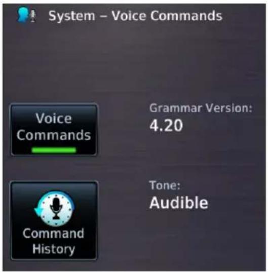
VOICE COMMAND HISTORY
Tap Command History to view a list of recently spoken commands.
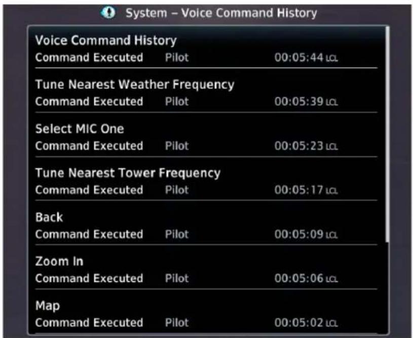
For a list of available voice recognition commands, consult Telligence Voice Command Guide.
Audio Panel Alert

If the audio panel fails:
- Red "X" displays over all audio panel-related controls
• Advisory message alerts - Audio panel, intercom, and Telligence Voice Command functions are not available
Audio panel fail annunciations are designed to be immediately recognizable.
If a failure occurs while a control page is active, the display automatically returns to the previous view.
For information regarding pilot response to a GMA 35 audio panel failure, consult the AFMS.
XPDR
XPDR Control Panel

Transponder controls are accessible via the XPDR key. This key is unavailable when the control panel is active.
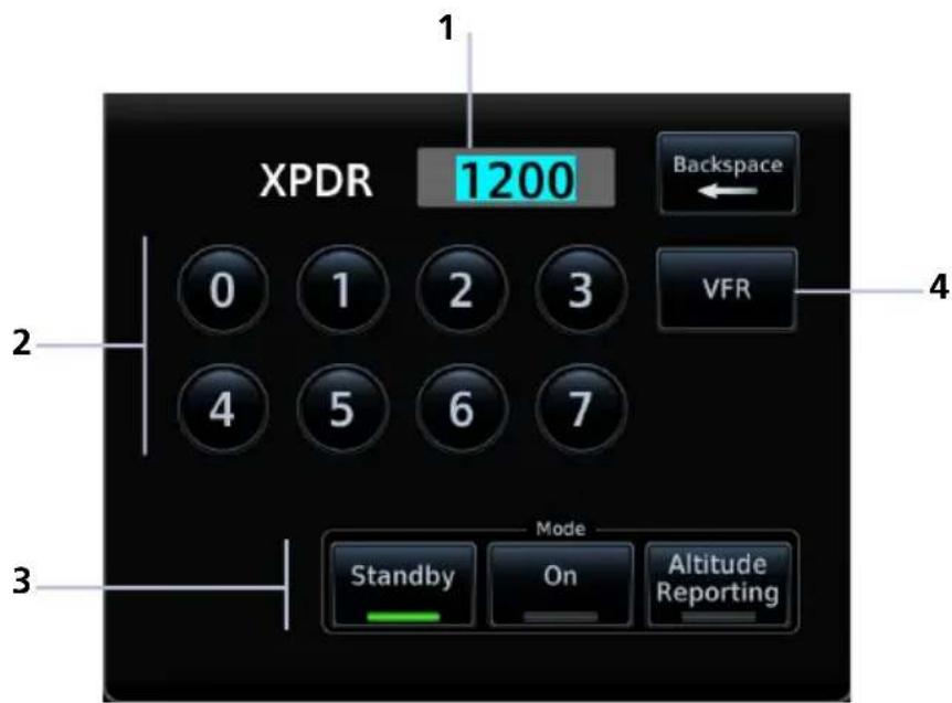
1 Squawk Code Entry Field 3 XPDR Mode Selection Keys
2 Squawk Code Entry Keys 4 VFR Key
The XPDR key becomes available when you:
- Enter a squawk code
- Open the XPDR menu
• View a message - Select the Mode key
- Leave the control panel
XPDR Setup
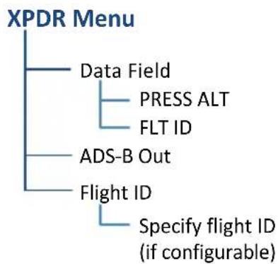
flowchart
graph TD
    A["XPDR Menu"] --> B["Data Field"]
    A --> C["Press ALT"]
    A --> D["FLT ID"]
    A --> E["ADS-B Out"]
    A --> F["Flight ID"]
    F --> G["Specify flight ID (if configurable)"]
Tap Menu to access the transponder setup options. From here you can:
• Change the display of data
- Enable 1090 ES ADS-B Out functionality (if configured)
- Assign a unique flight ID
Enable ADS-B Out Transmissions

Tapping ADS-B Out allows the transmission of ADS-B Out messages and position information.
Assign a Flight ID
FEATURE LIMITATIONS
• Availability dependent upon configuration

If the flight ID is editable, tap Flight ID and assign a unique identifier.
Flight IDs are alphanumeric (upper-case only) and have an eight character limit. The active flight ID displays by default.
XPDR Modes
Tapping Mode opens a menu of the available transponder modes. Options include Standby, On, and Altitude Reporting.
MODE OPTIONS
Standby
• Transponder does not reply to interrogations or transmit ADS-B Out
- Bluetooth wireless functions remain operational
- Unit continues to receive ADS-B In information, but is not a TIS-B participant
- Transponder replies to interrogations. Replies do not include pressure altitude
On
- Reply (R) symbol on the display indicates the transponder is responding
- Transmitted ADS-B Out does not include pressure altitude
Altitude Reporting
- Transponder replies to identification and altitude interrogations
- Reply (R) symbol indicates the transponder is responding
• Transmitted ADS-B Out includes pressure altitude
During Altitude Reporting mode, all aircraft air/ground state transmissions are handled via the transponder and require no pilot action. Always use this mode while in the air and on the ground, unless otherwise requested by ATC.
Squawk Code Keys
| SPECIAL SQUAWK CODES | |
| 1200 | Default VFR code (USA) |
| 7500 | Hijacking |
| 7600 | Loss of communications |
| 7700 | Emergency |
Eight squawk code entry keys (0 - 7) provide access to all ATCRBS codes. Tapping one of these keys begins the code selection sequence.
Use the Backspace key or outer control knob to move the cursor.

Digits that are not yet entered appear as underscores.
Activate the new code by tapping Enter. To cancel the code entry and exit the page, tap Cancel.

Active squawk codes remain in use until a new code is entered.
VFR
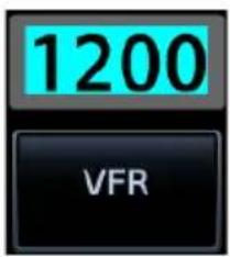
Tapping this key once sets the squawk code to the preprogrammed VFR code.
This code is factory set to 1200, but may be changed during configuration.
XPDR Key
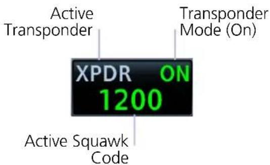
Tapping the XPDR key activates the IDENT function for 18 seconds. This signal distinguishes the transponder from others on the air traffic controller's screen.
Tapping this key when another page is active immediately opens the control panel.
TRANSPONDER STATUS INDICATIONS
IDENT Standby Mode

- Reply active
• IDENT function active
• No change to transponder code

- Standby mode
- Current squawk code (inactive)
IDENT with New Squawk Code Altitude Reporting Mode

- Reply active
• Transponder code modified
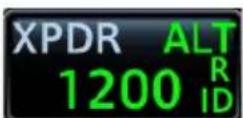
• Altitude reporting mode
- Reply active
• Identify function active
• VFR squawk code (active)

Reply active

IDENT function active

Transponder in operation

Altitude Reporting

Standby

Tap to initiate the IDENT function (code unmodified)

Tap to accept modified code and initiate IDENT function
XPDR Alert

If the transponder fails:
- Red "X" displays over the IDENT key
• Advisory message alerts
• XPDR control page is not available
Transponder fail annunciations are designed to be immediately recognizable.
If a failure occurs while the control page is active, the display automatically returns to the previous view.
For information regarding pilot response to a transponder failure, consult the AFMS.
ADS-B Altitude Reporting
FEATURE REQUIREMENTS
• GDL 88
FEATURE LIMITATIONS
• Display and control functionality dependent upon GDL 88 configuration
ADS-B Control Panel

ADS-B Out controls are accessible via the ADS-B key. The location of this key varies by unit type.
When interfaced to a GDL 88 transceiver, GTN Xi allows control over some aspects of the ADS-B Out message and provides position information to the GDL 88.
Not all installations allow pilot control of ADS-B Out transmissions.
GDL 88 Features
- Remote-mount ADS-B transceiver
• Transmits ADS-B Out messages to ATC and other aircraft - Communicates ADS-B In data to panel-mounted avionics for the display of traffic and weather
For more information, consult the GDL 88 ADS-B Transceiver Pilot's Guide.
ADS-B Key
FEATURE LIMITATIONS
• Functionality dependent upon GDL 88 configuration
Transponder Mode (ALT)
ADS-B ALT 1200
Squawk Code (as reported by GDL 88)
Depending on the configuration of your GDL 88, tapping the ADS-B key:
• Reports GDL 88 altitude reporting status
OR
- Allows on/off control of the GDL 88's altitude reporting function
Report ALT On
Control Panel Annunciation
"ALT" indicates that the unit is in altitude reporting mode. This indication corresponds to the function status annunciation on the control panel.
Enable Anonymous Mode
FEATURE LIMITATIONS
• Availability dependent upon GDL 88 configuration
During anonymous mode, the unit replaces identifying information in the ADS-B Out message with a temporary randomized number for privacy while providing position information. Instead of a flight ID, the unit transmits the call sign "VFR."

Tap ADS-B > Anonymous.
The key label changes from "Off" to "Armed."
Tapping Anonymous again toggles the mode off.
Assign a Flight ID
FEATURE LIMITATIONS
• Availability dependent upon GDL 88 configuration
If the flight ID is editable, tap Flight ID and assign a unique identifier. The key is not selectable (read-only) when the ID is received from the GDL 88.
Flight IDs are alphanumeric (upper-case only) and have an eight character limit. The active flight ID displays by default.
GDL 88 Alert
If the GDL 88 fails:
- Red "X" displays over the ADS-B key
• Advisory message alerts
• ADS-B reporting functions are not available
Failure annunciations are designed to be immediately recognizable. If a failure occurs while the control page is active, the display automatically returns to the previous view.
For information regarding pilot response to ADS-B failures, consult the AFMS.
Pilot Settings

Unit customization options are accessible via the System menu. For details about COM/NAV radio settings and Connext Setup options, refer to the respective section.
Setup
- Set CDI scale and capture type
- Specify nearest airport runway criteria
- Set time format & local offset
- Select a new start-up page
- Select a keyboard type
- Enable crossfill functionality
- Access NAV radio settings (GTN 650Xi/750Xi only)
- Access COM radio settings (GTN 635Xi/650Xi/750Xi only)

Alerts
- Set airspace & arrival alerts

Audio
- Adjust click volume
Units
- Set the display units

Backlight
- Adjust display brightness
User Fields
- Select user fields ^1

Page Shortcuts
- Customize page shortcuts for knob access

Other setup options allow you to monitor time in flight and create custom reminder messages. These settings reside in the system Utilities.

Flight Timers
• Set departure & trip timers
- Set a generic timer for general timing needs
Alerts
- Set custom reminder messages and when they display
CDI Scale
WHERE TO FIND IT
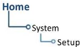
flowchart
graph TD
    A["Home"] --> B["System"]
    B --> C["Setup"]
Set the scale for the course deviation indicator. Scale values represent full scale deflection for the CDI to either side.
Options: • 0.30 nm • 1.00 nm • 2.00 nm • Auto
Scale selections are reflected in the annunciator bar.
Auto Setting Annunciation Manual Setting Annunciation
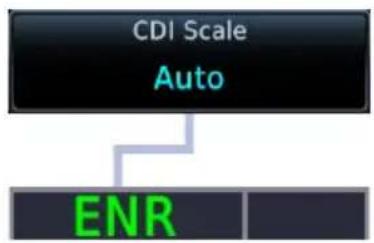
flowchart
graph TD
    A["CDI Scale"] --> B["Auto"]
    B --> C["ENR"]

CDI scale is set to "Auto" (default). At the default setting, the scale sets to 2.0 nm during the en route phase of flight.
Aircraft is within 31 nm of the destination airport (i.e., terminal area).
The scale linearly ramps down to 1.0 nm over a distance of 1 nm.
Aircraft is leaving the departure airport. The scale is set to 1.0 nm once the aircraft is over 30 nm from the departure airport. It begins to gradually ramp up to 2 nm when the flight phase changes from terminal (TERM) to en route (ENR).
During GPS approach operations, the scale gradually transitions down to an angular scale.
Aircraft is 2.0 nm before the final approach fix. Scaling tightens from 1.0 nm to the angular full-scale deflection defined for the approach (typically 2.0°).
Selecting a lower value (0.3 nm or 1.0 nm) prevents the selection of higher scale settings during ANY phase of flight. Example: If you select 1.0 nm, the unit uses this setting for en route and terminal phases, and ramps down further during approach.
Horizontal Alarm Limits
Horizontal alarm limits (HAL) are used to compare against GPS position integrity. These protection limits follow the CDI scale, unless the corresponding flight phase requires a lower HAL. For example, the selected scale setting is 1.0 nm, but full-scale deflection during approach still follows the approach scale setting (0.30 nm).
| FLIGHT PHASE | CDI SCALE | HORIZONTAL ALARM LIMIT |
| Approach 0.30 nm or Auto 0.30 nm | ||
| Terminal 1.00 nm or Auto 1.00 nm | ||
| En Route 2.00 nm or Auto 2.00 nm | ||
| Oceanic Auto 2.00 nm |
ILS CDI Capture
FEATURE LIMITATIONS
Automatic switching is not available for aircraft equipped with a KAP 140/KFC 225 autopilot.

Tapping this key sets the manner in which ILS CDI capture occurs: automatically or manually
This function may not be available in certain installations.
Auto Switch Manual Selection
GTN Xi automatically switches the external CDI from GPS to VLOC on ILS approach.
Allows you to manually switch the external CDI connection using the CDI key.
For more about ILS approaches, refer to the Procedures section.
Startup Page
WHERE TO FIND IT

flowchart
graph TD
    A["Home"] --> B["System"]
    B --> C["Setup"]
Customize the default display page. This option resides in the System Setup app.
Tap Startup Page and select from the menu of available page options.
Page Options:
- Charts ^1 • Connext Weather • DALT/TAS/Winds • Default NAV ^2
- Emergency • FIS-B Weather • Flight Plan • Flight Timers • Fuel Planning
- Home (default) • Map • Nearest Airport • Procedure • Radar • Sirius XM
- Stormscope • Terrain • Traffic • Trip Planning • VCALC • VNAV
- Waypoint Info - Airport • Waypoint Info - VOR • Weather
Keyboard Type
WHERE TO FIND IT
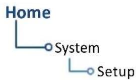
flowchart
graph TD
    A["Home"] --> B["System"]
    B --> C["Setup"]
Select a preferred keyboard type for use during alphanumeric data entry operations. This option resides in the System Setup app.

Tapping this key opens a menu of available keyboard types. Options and layout vary according to display size.
| KEYBOARD TYPE | GTN Xi SERIES | |
| 650 750 | ||
| Alphabetical (ABC) • • | ||
| U.S. standard (QWERTY) • • | ||
| Slider • | ||
Nearest Airport Runway Criteria
Specify runway criteria to determine which airports appear on the Nearest Airport page.
WHERE TO FIND IT

flowchart
graph TD
    A["System"] --> B["Setup"]
    B --> C["Nearest Airport"]
Customization options are accessible via the System Setup app.
To avoid nuisance alerts during an approach, separate airport runway settings may be configured for the TAWS/HTAWS alerting function. Contact your installer for information about these settings.
Nearest airport runway criteria do not affect the best glide airport indicator. Contact a Garmin dealer to adjust runway criteria for this specific feature.
RUNWAY SURFACE
Runway Surface Options
Any
- Hard Only
- Hard/Soft
Water
Tap Runway Surface and then select the runway surface type.
Selecting "Any" allows all surface types to appear in the nearest airport list and be considered for use by Terrain.
MINIMUM RUNWAY LENGTH
Specify a minimum runway length to:
- Exclude airports with shorter runways from the nearest airport list
- Inform the terrain function of which airports are available for use, so that terrain alerts do not generate when landing at one of these airports
Typing “0” allows runways of any length to appear in the nearest airport list and be considered for use by Terrain.
INCLUDE USER AIRPORTS

You can include user-defined airports in your nearest airport search. Deselecting this key excludes user airports from the search criteria.
Clocks & Timers
Timers

Monitor time in flight using three available timer types.
WHERE TO FIND IT

flowchart
graph TD
    A["Home"] --> B["Utilities"]
    B --> C["Flight Timers"]
Timer settings are accessible via the Utilities menu page. Toggle between timer types using the provided display key.
Clock/Generic Timer Trip/Departure Timers
Stopwatch style counter.
Count up or count down.
Specify countdown time using the preset function.
Measure elapsed airborne time since the last ground-to-air transition. Set timer to start at unit power up or once the aircraft is in air.
Controls:
- Direction (Up, Down)
- Start • Stop • Timer Preset
- Reset Timer
Controls:
• Criteria (Power On, In Air)
- Reset Timer
Clock
WHERE TO FIND IT

flowchart
graph TD
    A["Home"] --> B["System"]
    B --> C["Setup"]
Specify the time format and local offset. Settings reside in System Setup.
Format options include Local 12 hour, Local 24 hour, and UTC.
If a 12 hour or 24 hour clock is selected:
Tap Local Offset > Specify the appropriate offset value from UTC.
Page Shortcuts

A knob shortcut option allows you to customize up to seven slots on the locater bar.
FEATURE LIMITATIONS
• Available shortcut options are dependent upon unit type and configuration.
- You may assign each page to only one knob slot on GTN Xi. Duplicating a page shortcut in a second slot will turn off the existing shortcut slot.

Tap a slot key and assign a page to that slot. Verify shortcut operation once complete.
Slots one and nine are reserved for navigation purposes. They are not editable.
Page Options:
Not all options may be available.
| APT Airport Info NAV Default Navigation | 4 | ||
| CHK Checklist NRST Nearest Airport | 5 | ||
| CHRT Charts | 1 | PROC Procedure | |
| CNXT Connext Weather | 2 | SXM SiriusXM Weather | 2 |
| E6B DALT/TAS/Winds TERR Terrain | |||
| EMRG Emergency | TIME Flight Timers | ||
| FIS FIS-B Weather | 2 | TRFC | Traffic^2 |
| FPL | Active Flight Plan | TRIP | Trip Planning |
| FUEL | Fuel Planning | VOR | VOR Info |
| LTNG | Stormscope^2 | WXR Radar | 1, 2 |
| MAP | Map^3 | OFF | Do not display shortcut |
RESTORE DEFAULTS

Tapping Restore Defaults returns all slots to their default settings.
This option resides in the setup menu.
^1 GTN 750Xi Series only. ^2 Dependent upon unit configuration.
^3 Assigned to slot 1 by default (GTN 750Xi Series only).
^4 Assigned to slot 1 by default (GTN 650Xi Series only). ^5 Assigned to slot 9 by default.
Alerts Settings

Receive alert messages when nearing your destination and/or entering a specific airspace type.
FEATURE LIMITATIONS
- Alert altitudes are dependent upon aircraft and airspace altitudes and the pilot-specified altitude buffer value
Arrival Alerts
Arrival alerts generate a message when the aircraft is within a specified proximity of the destination. Distance units are based on the System Units setting.
ENABLE AN ARRIVAL ALERT
Tap Arrival > Proximity, then enter a distance value.
Airspace Alerts
Airspace alerts generate a message and filtering of the Nearest Airspace list. They rely on three-dimensional data (altitude, latitude, and longitude) to avoid nuisance alerts.

Control keys allow you to select which airspace boundaries generate an alert annunciation upon entry.
Airspace Alert Options
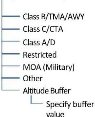
Alert boundaries for controlled airspace are sectorized to provide complete information on any nearby airspace.
Alert settings do not alter the depiction of airspace, nor do they change Smart Airspace settings on the Map page.
With the exception of Altitude Buffer, airspace alert options are on/off only.
Airspace alerts for Prohibited airspace cannot be disabled.
Unit Selections

Customize the display unit settings. Tapping a parameter key opens a menu of the available unit types.
| PARAMETER SETTINGS | |
| Altitude/Vertical Speed | Feet (ft/fpm) • Meters (m/mps) |
| Distance/Speed | Nautical Miles (nm/kt) • Statute Miles (sm/mph)Kilometers (km/kph) |
| Fuel | Gallons (gal)• Liters (lt)Imperial Gallons (lg)• Pounds (lb)Kilograms (kg) |
| Magnetic Variation | Specify number of degrees for east or west (°E, °W)Available only when “User (°U)” is the active NAV angle |
| NAV Angle | Magnetic (°)• User (°U)True (°T)• External1 |
| Position Format | LAT/LON DD.D°• UTMLAT/LON DD°MM.M'• Swiss GridLAT/LON DD°MM'SS"• Irish GridMGRS• British National Grid |
| Pressure | Inches in Mercury (in)• Millibars (mb)Hectopascals (hPa) |
| Temperature | Celsius (°C)• Fahrenheit (°F) |
^1 Availability dependent upon configuration.
SPECIFY UNIT TYPE
- Review the current unit selections.
- Tap the applicable parameter key.
- Select a unit type.
User Selected NAV Angle

NOTE
When changing NAV angle, be aware that the DTK for an approach does not change on the active flight plan until you reload the approach.
Selected NAV angle units are applied to all angular values.
Options:
Magnetic External
Corrects all track, course, and heading information to the magnetic variation computed by the GPS receiver.
Synchronizes GTN Xi NAV angle with the local MFD. Availability is dependent upon configuration.
True User
References all information to true north.
Allows you to manually set a magnetic variation value between 0^ and 179^ E or W.
Position Formats
The selected format is used in all locations where position information is available. Format detail is as follows.
MGRS

UTM

REGIONAL POSITION FORMATS
By default, GTN Xi displays lat/lon for any positions outside the grid region.
British National Grid Irish National Grid

scatter
| Grid Designator | Value | | --------------- | ------- | | SP | 44349 | | Northing Value | 97868 | | R | 51544 | | Easting Value | 37202 |Swiss National Grid
Easting Value
2618397 1159098
Northing Value
Click Volume

Your GTN Xi is wired for audio output. Set the click volume to the preferred level.
Click Volume Control

bar
| Category | Value | | ---------------- | ----- | | Percent of Max Volume | 62% | | Decrease Volume | Left left | | Increase Volume | Right right |Volume displays as a percentage of the maximum volume, with 0% being muted and 100% being maximum volume.
HTAWS Voice Alert Options
FEATURE REQUIREMENTS
HTAWS
An optional voice callouts may be available for units configured for HTAWS alerting. To set the volume, tap Voice Callouts > MAX Voice Callout, and set a value.
Voice Callout Availability
- Down to 100 ft above terrain when HTAWS is present and GSL above terrain is used to generate callouts (no radar altimeter)
- Down to 50 ft above terrain when a radar altimeter is present and supplying the height above terrain to generate callouts
Display Brightness Control

Depending on configuration, display brightness is controlled using inputs from the built in photocell, aircraft dimmer bus, or both.
Automatic Brightness Control
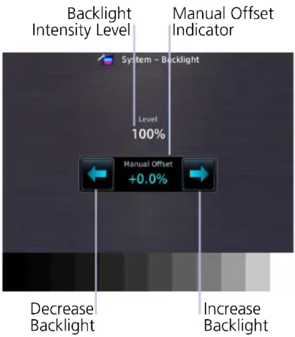
Dimming is limited to prevent on-screen indications from becoming unreadable. The built in photocell automatically controls display brightness based on ambient light levels.
During automatic control, you may still adjust brightness using the manual offset controls in the Backlight page.
The unit retains manual offset settings over power cycles.
Manual Brightness Control
Optionally, the unit is configurable to use an aircraft dimming bus for display brightness control. Upon reaching minimum input level, display brightness reverts to the photocell. This prevents the display from going black in the event of a dimmer input failure.
Installer configured curves determine the amount of change in brightness that occurs in response to a control adjustment.
If brightness control is not satisfactory, contact a Garmin dealer to adjust the lighting curves.
Scheduled Messages

Create custom reminder messages and set when they will display. Allows one time, periodic, and event-based message types.
WHERE TO FIND IT

flowchart
graph TD
    A["Home"] --> B["Utilities"]
    B --> C["Scheduled Messages"]
Active reminders appear at the top of the scheduled message list. This list is accessible via the Utilities menu page.
Examples: • "Call FBO" • "Close flight plan" • "Switch fuel tanks"
CREATE A REMINDER MESSAGE
- Tap Create Scheduled Message.
- Specify the message type, content, and countdown timer value.
Message Types
TYPE DISPLAYS...
| One time | When the timer expires, or following each power cycle until message deletion. |
| Periodic | After a specified duration of time. Countdown repeats once the message displays. |
| Event | According to a specified date and time. Message timer not applicable. |
Modifying Scheduled Messages
Once created, these messages may be modified at any time. Selecting a scheduled message opens an options menu.
EDIT MESSAGE
This function is accessible from either the Scheduled Messages page or the system message list.
RESET TIMER
Restarts the countdown timer.
DELETE MESSAGE
Confirming this request removes the selected message from the list.
Crossfill
FEATURE REQUIREMENTS
• Dual GTN configuration
Enable the crossfilling of information between two GTN units.
Crossfill Features
- Enabling this function on one GTN automatically enables it on the other.
• Some types of data crossfill regardless of the current setting
WAYPOINT IDENTIFIERS
When crossfilled from GTN to GNS, duplicate waypoint names, or names exceeding six characters in length, are shortened. A “+” sign replaces certain characters while leaving significant characters to aid in identification (e.g., USR003 becomes US+003).
GTN to GTN Data
Alerts:
• Traffic pop-up acknowledgment
• Missed approach waypoint popup acknowledgment
• Altitude leg pop-up acknowledgment
External Sensors:
- Synchro heading
• Transponder status and commands
Flight Plan Catalog
System Setup:
• User-defined NAV frequencies
• Date/Time convention
- Nearest airport criteria
• Units (Nav angle, Fuel, and Temperature)
• User-defined COM frequencies
- CDI Scale setting
• ILS CDI Capture setting
User waypoints
Includes active flight plan navigation data if you turn on the crossfill function.
Get Started
If configured, a system message alerts you when the function off (i.e., flight plans are not crossfilling).
To enable or disable crossfilling:
Home > System > Setup > Crossfill > OK
GTN to GNS Data
GTN to GNS GNS to GTN
Active flight plans
Active direct to
User waypoints
User waypoints
To enable crossfilling:
Home > System > Setup > GNS Crossfill Settings > Auto GNS Crossfill
Status Indications
Alert Types
The unit generates annunciations in response to various conditions that may occur. These abbreviated messages include:
- Warnings
- Cautions
• Function and mode advisories
WARNINGS & CAUTIONS
Warnings require immediate attention. Cautions indicate the presence of an abnormal condition that may require pilot action. A warning may follow a caution if no attempt is made to correct the condition (e.g., altering the aircraft's path to avoid the alerted terrain or obstacle).
FUNCTION & MODE ADVISORIES
Advisories provide status and operating information.
System advisories. These display on a dedicated message list. Depending on the number of advisories, this list may be scrollable.
Function or mode specific advisories. These appear as unobstructed annunciations in the annunciator bar.
For a complete list of all system-related advisories, refer to section 8.
Alert Annunciations
Alert annunciations are abbreviated messages that indicate an alerted function or mode. The color of the annunciation depends on the alert type.
| ALERT COLORS |
| WARNING |
| CAUTION |
| ADVISORY |
- Warnings display in white text on red background
- Cautions display in black text on amber background
• Function or mode specific advisories display in black text on white background
When an alert is triggered, the annunciation flashes by alternating text and background colors. It turns solid after five seconds. All annunciations remain active (solid) until the condition is resolved or no longer a threat.
ANNUNCIATION LOCATION
Alerts and informational advisories annunciate along the bottom of the screen.
| Alerts, Inhibits,& Test ModeAdvisories | Phase | GPS Signal& DemoMode | CDISource | Procedures Flight | Waypoint& COM/NAVAdvisories |
| PULL UP | LNAV | LOI | GPS | SUSP | Arriving at waypoint |
Annunciator Bar
Pop-up Alerts
If a warning or caution relating to terrain or traffic occurs, a pop-up window may display. These pop-ups only appear if the alerted function's associated page is not active.
Pop-up Alert Priority
In the event of simultaneous alerts, pop-up windows display in the following order:
- Terrain alerts
- Traffic alerts
Each pop-up alert provides:
- Threat indication
- Alert annunciation
- Alert inhibit or mute option depending on threat and system configuration
• Control for closing the pop-up window - Direct access to the associated page
GTN 750Xi Series

GTN 650Xi Series

Terrain Pop-up Alert Layout
| 1 Enlarged Page View 4 Go to Terrain Page Key | |
| 2 Threat Indication 5 Alert Inhibit Key | |
| 3 Close Pop-up Window Key | |


Traffic Pop-up Alert Layout
| 1 Enlarged Page View 4 Go to Traffic Page Key | |
| 2 Threat Indication 5 Mute Alert Key | 1 |
| 3 Close Pop-up Window Key | |
To open the indicated page, tap Go to
To acknowledge the alert and return to previous page view, tap Close.
For information about the terrain alert inhibit function, read Alert Inhibit, TAWS & Terrain Alerting in section 5. For information about the traffic alert mute function, read Aural Alerts in this section.
^1 ADS-B traffic only.
Aural Alerts
Some alerts are accompanied by an aural voice message. Voice gender is configured during installation. To determine which alerts provide aural indications, refer to the applicable alerts table(s) in the Hazard Awareness section.
MUTE ALERT
FEATURE LIMITATIONS
• Available only with GTX 345 and ADS-B software v3.20 or later

Tapping Mute Alert silences the active traffic alert. This key is available on the traffic alert pop-up.
The mute alert function is applicable only to the active aural alert. It does not mute future alerts.
System Status
View information specific to the unit and its software. Refer here when contacting customer service.
SYSTEM INFO CONTROLS
- Serial number
- System ID
- Main software version
• GPS/WAAS software version
• COM board software version (GTN 635Xi, 650Xi, 750Xi only)
• NAV board software version (GTN 650Xi, 750Xi)
Database Info access keys:
Active
- Standby
For more about active and standby databases, read Databases.
GPS Status

Monitor GPS receiver performance, establish a baseline for normal system operation, and troubleshoot weak or missing signal issues.
This page provides a visual reference of GPS receiver functions, including:
• Current satellite coverage
• GPS solution and receiver status
• Phase of flight • Position accuracy
• Present position (latitude and longitude)
SKY VIEW DISPLAY

radar
| Value | |---| | 26 | | 16 | | 27 | | 23 | | 08 | | 4(45)B | | 03 | | 30 | | 07 | 09 | | 02 | | 05 |- Depicts satellites currently in view as well as their respective positions
• Outer circle represents the horizon (with north at the top of the circle)
• Inner circle represents 45^ above the horizon
• Center point shows the position directly overhead
SIGNAL STRENGTH INDICATIONS
Satellite SVIDs
Each bar is labeled with the SVID of the corresponding satellite. Numbers vary according to satellite type.
• GPS: 1 to 31
• SBAS: 120 to 138
A graph shows GPS signal strength for up to 15 satellites. As the GPS receiver locks onto satellites, a signal strength bar appears for each satellite in view.
Graph symbols depict the progress of satellite acquisition. Some data may not display until the unit has acquired enough satellites for a fix.

bar
| X-Axis | Value | |---|---| | 01 | 1 | | 02 | 3 | | 03 | 4 | | 05 | 6 | | 06 | 7 | | 07 | 8 | | 08 | 9 | | 10 | 12 | | 11 | 13 | | 12 | 14 | | 13 | 15 | | 15 | 18 | | 35 | 4 | | 40 | 8 | | 45 | 16 |SYMBOL CONDITION
| Not present Receiver is searching for the indicated satellites. | |
| Gray bar, empty | Satellite located. |
| Gray bar, solid | Satellite located, receiver is collecting data. |
| Yellow bar, solid | Data collected, but satellite is excluded from position solution (i.e., it is not in use). |
| Cyan bar,cross-hatch | Satellite located, but FDE excludes it for being a faulty satellite. |
| Cyan bar, solid | Data collected, but receiver is not using satellite in the position solution. |
| Green bar, solid | Data collected, satellite in use in the current position solution. |
| D (inside bar) | Differential corrections are in use (e.g., WAAS). |
If the unit has not been in operation for more than six months, acquiring satellite data to establish almanac and satellite orbit information may take 5 to 10 minutes.
POSITION ACCURACY FIELDS
LABEL POSITION DATA
EPU Estimated Position Uncertainty
HDOP Horizontal Dilution of Precision
HFOM Horizontal Figure of Merit
VFOM Vertical Figure of Merit
EPU is the horizontal position error estimated by the fault detection and exclusion (FDE) algorithm, in feet or meters.
Information fields indicate the accuracy of the position fix.
HFOM and VFOM values represent 95% confidence levels in horizontal and vertical accuracy.
Lower values mean higher accuracy. Higher values are the least accurate.

NOTE
Under FAR parts 91, 121, 125, and 135, the FDE availability prediction program must be used prior to all oceanic or remote area flights using GTN Xi as a primary means of navigation.
Circle of Uncertainty
FEATURE LIMITATIONS
• Available only when the aircraft is on ground
• Displays only on Map
Circle of Uncertainty

- Depicts area surrounding the ownership when GPS cannot accurately determine aircraft location
- Expands as GPS horizontal accuracy degrades
• Shrinks as accuracy improves - Translucent with minor shading so as not to obstruct other features
SBAS Providers

NOTE
Operating with SBAS active outside of the service area may cause elevated EPU values to display on the status page. Regardless of the EPU value displayed, the LOI annunciation is the controlling indication for determining the integrity of the GPS navigation solution.
SBAS supports wide area or regional augmentation through the use of additional satellite broadcast messages.
Tap this key and select from the list of providers.
PROVIDER SERVICE AREAS
| EGNOS | Most of Europe and parts of North Africa. |
| GAGAN | India only. |
| MSAS | Japan only. |
| WAAS | Alaska, Canada, the 48 contiguous states, and most of Central America. |
GPS Status Annunciations
Once the GPS receiver determines the aircraft's position, the unit displays position, altitude, track, and ground speed data. GPS status annunciates under the following conditions.
ANNUNCIATION CONDITION
| Acquiring | GPS receiver uses last known position and satellite orbital data (collected continuously from satellites) to determine which satellites should be in view. |
| 3D Nav | 3D navigation mode. GPS receiver computes altitude using satellite data. |
| 3D Diff Nav | 3D navigation mode. Differential corrections from SBAS provider are in use. |
| LOI | Satellite coverage is insufficient to pass built-in integrity monitoring tests. |
GPS Alerts
The following alert conditions can affect GPS accuracy.
INDICATIONS FAULT TYPE CONDITION
| Yellow “LOI” annunciation. | Loss of Integrity | Integrity of the GPS position does not meet the requirements for the current phase of flight. Occurs before the final approach fix (if an approach is active). |
| Unit invalidates active course guidance. Annunciation is specific to cause. | Loss of Navigation | Aircraft is after the final approach fix and GPS integrity does not meet the active approach requirements. |
| Insufficient number of satellites supporting aircraft position (i.e., more than 5 seconds pass without adequate satellites to compute a position). | ||
| GPS sensor detects an excessive position error or failure that cannot be excluded within the time to alert. | ||
| On-board hardware failure. | ||
| Yellow “No GPS Position” annunciation. Ownership icon not present | Loss of Position | Unit cannot determine a GPS position solution. |
For information about managing limited navigation features, read Dead Reckoning in section 3.
LRU Status
Devices that interface to the system via Ethernet display product information and connection status on the External LRUs list.

The device is configured and communicating properly.

The device is not available and is not configured, or it is not communicating properly.

Some interfaced equipment provide controls for product registration, enablement, or viewing detailed status information.
To access these features, tap More Info.
Logs
natural_image
Icon depicting a notepad and a stack of documents, labeled 'Logs' (no additional text or symbols)The data logging function is capable of storing approximately 100 hours of flight data in the unit's internal memory. This information is available for export to an SD card for later analysis.
FEATURE REQUIREMENTS
• SD card for external data logging
• Flight Stream 510 wireless datacard for data streaming
• Flight Stream 510 and GDU TXi for engine data streaming
Flight Data Log Functions
- Records log files automatically while the unit is powered up, including various parameters related to aircraft flight instruments
• Overwrites oldest file when the internal log reaches capacity - Exports to the "logs" folder on the SD card
• Streams logged flight ^1 and engine ^2 data to Garmin Pilot
WAAS Diagnostic Log Functions
- Records log files automatically while the unit is powered up
• Overwrites oldest file when the internal log reaches capacity - Exports to the "logs" folder on the SD card
FILE NAMING CONVENTIONS
Log file names provide a useful reference to aid data analysis. They include:
- Log start date and time
- Identifier of the nearest waypoint at the indicated start time
log\_YYMMDD\_HHMMSS\_WPT.csv

flowchart
graph LR
    A["Year Month Day"] --> B["Hour Minute Second"]
    B --> C["Nearest Waypoint Identifier (at start of log)"]
Files with the name "log_000101_0000XX____.csv" do not contain a valid date and time stamp. These logs may include data recorded during installation.
Data Logging at a Glance
To automatically upload data to flyGarmin, install Flight Stream into GTN Xi or GDU TXi.

flowchart
graph TD
    A["GARMIN"] -->|GDU TXi| B["connext"]
    B -->|GTN Xi| C["GNTP"]
    C -->|GARMIN| A
    style A fill:#f9f,stroke:#333
    style B fill:#ccf,stroke:#333
    style C fill:#cfc,stroke:#333
Upon power up, GTN Xi begins logging flight data automatically, storing the data in its internal memory.
If Flight Stream is present in GDU TXi:
• GDU TXi streams data to Garmin Pilot via Flight Stream ^1
If Flight Stream is present in GTN Xi:
- GDU TXi transfers logs to GTN Xi, which then streams the data to Garmin Pilot via Flight Stream ^1
• GTN Xi is the preferred location for Flight Stream installation
If an SD card is present in GTN Xi:
- Pilot uses the export function to write GTN Xi data to the SD card
What happens if there's a power interruption?
Data logging stops if power is lost. All data recorded up to that point remains stored in the internal memory. Data is not recorded for the duration of the outage. When GTN Xi reboots, data logging automatically resumes with a new log file.
Export to an SD Card

NOTE
Do not eject the SD card while the export function is in progress. Wait until the selected log key is available before ejecting the card.
WHERE TO FIND IT

flowchart
graph TD
    A["Home"] --> B["Utilities"]
    B --> C["Logs"]
Export a flight data log to an SD card for later analysis.
- Insert an SD card.
- Tap Utilities > Logs.
- Select WAAS Diagnostic Log or Flight Data Log.
If no log files are present, these keys are not available.

During export, the selected log key is unavailable (gray). It becomes available once export is complete.
The key label changes to indicate export in progress.
What if I forget to insert my SD card before flight?
Internal flight data logging occurs regardless of whether an SD card is present. After your flight, you may insert a card and download log files using the Flight Data Log command.
With the aircraft safely on ground:
- Power off unit.
- Insert card.
- Power on unit.
- Tap Utilities > Logs > Flight Data Log.
Wait for the export to complete before ejecting the SD card.
Once the files are exported onto an SD card, you may transfer the log files to your personal logbook on flyGarmin.com.
Duration varies depending on the number of files present. For lengthy transfers, it may be necessary to run the engine or operate on ground power until the export is complete.
TRANSFER SD CARD DATA TO YOUR ONLINE LOGBOOK
The Logbook tab on flyGarmin.com provides functions for creating and viewing multiple logbook entries.
flyGarmin Navigation Tabs
| HOME | DEVICES | GARMIN PILOT | LOGBOOK | TRAINING | SUPPORT |
To create a logbook:
- Sign in to your flyGarmin.com account.
- Select Logbook > Setup.
- Select Add Aircraft Type.
- Provide all necessary aircraft type details, then select Save Aircraft Type.
- Provide all necessary settings and pilot information, then select Save Settings.
To upload flight logs to your logbook:
- Select Logbook > Entries > Upload Flight Logs.
- Select and upload log files according to the onscreen instructions.
Streaming to Garmin Pilot

The unit automatically streams logged flight data to the Garmin Pilot app when Flight Stream 510 is present and paired to a supported tablet or phone.

flowchart
graph TD
    A["flyGarmin.com"] -->|The data uploads to flyGarmin.com upon connecting to Wi-Fi with Internet.| B[" Garmin Pilot App "]
    B -->|Your portable device downloads the data upon connecting to Flight Stream 510.| C[" Garmin Pilot App "]
    C --> D[" Connected Devices"]
    D --> E[" Logged flight and engine data streams to Garmin Pilot. "]
    E --> A

This includes any previous flights not already downloaded.
What happens if I forget to bring my tablet on the flight?
No need to worry. During flight, GTN Xi records log data to the internal storage. The next time you fly with your tablet, the data will stream to Garmin Pilot. This includes all previously recorded flights. The device downloads the data upon connecting to Flight Stream 510.
3 Navigation
MAP 3-4
CHARTS....3-47
WAYPOINTS....3-53
ACTIVE FLIGHT PLAN.... 3-73
DIRECT TO.... 3-110
PROCEDURES.... 3-118
NAVIGATION APPS & FUNCTIONS
Selections vary based on features and optional equipment installed with Garmin avionics.

Map
• Display moving map
- Adjust detail level
- Customize map overlay features
- Edit user fields
• Graphically edit a flight plan
- Select a CDI source (GTN 750Xi only)

Charts
• View terminal procedures & airport surface diagrams
Waypoint Info
- Search waypoints
• Create & store user waypoints

Nearest
• View nearest waypoints, airspaces, or facilities

Flight Plan
• Create & edit a flight plan
• View active leg status
• Catalog & manage saved flight plans
- Specify a parallel course offset
- Import a flight plan

Procedures
- Load & activate procedures
• Activate a missed approach

Direct To
- Set a direct course to any waypoint
- Generate a custom hold
- Generate a search-and-rescue pattern

GTN 650Xi SERIES
Default NAV
- Configure user fields
- Enable OBS mode
- Select a CDI source (GTN 650Xi only)
Map

To increase situational awareness, Map depicts the aircraft's current position relative to land, aeronautical, weather, and traffic information.
FEATURE REQUIREMENTS
• Active GPS source (aircraft position symbol)
• Active weather subscription (Connext & SiriusXM only)
• FIS-B and GDL 88 or GTX 345 (FIS-B Weather)
• GDL 69/69A SiriusXM receiver (SiriusXM Weather)
- GDL 69, GDL 88, GTX 345, or GSR 56, with appropriate weather service subscription (NEXRAD/PRECIP overlay)
• GSR 56 Iridium satellite transceiver (Connext Weather)
• WX-series Stormscope receiver (Stormscope lightning data)
- Valid heading source (Radar, Stormscope & Traffic)
- Matching chart databases (dual GTN/crossfill configurations only)
- Traffic system
GTN 750Xi Series only:
• GWX 68/70/75/80 or ARINC 708 connected radar (airborne weather radar overlay)
- Valid charts database with effective database cycle; aircraft to be airborne (ChartView, FliteCharts)
FEATURE LIMITATIONS
- NEXRAD/PRECIP, Radar, and Terrain overlay functions are mutually exclusive; enabling one automatically disables the other
- Radar, Stormscope, and Traffic overlays do not display if user navigation angles are active
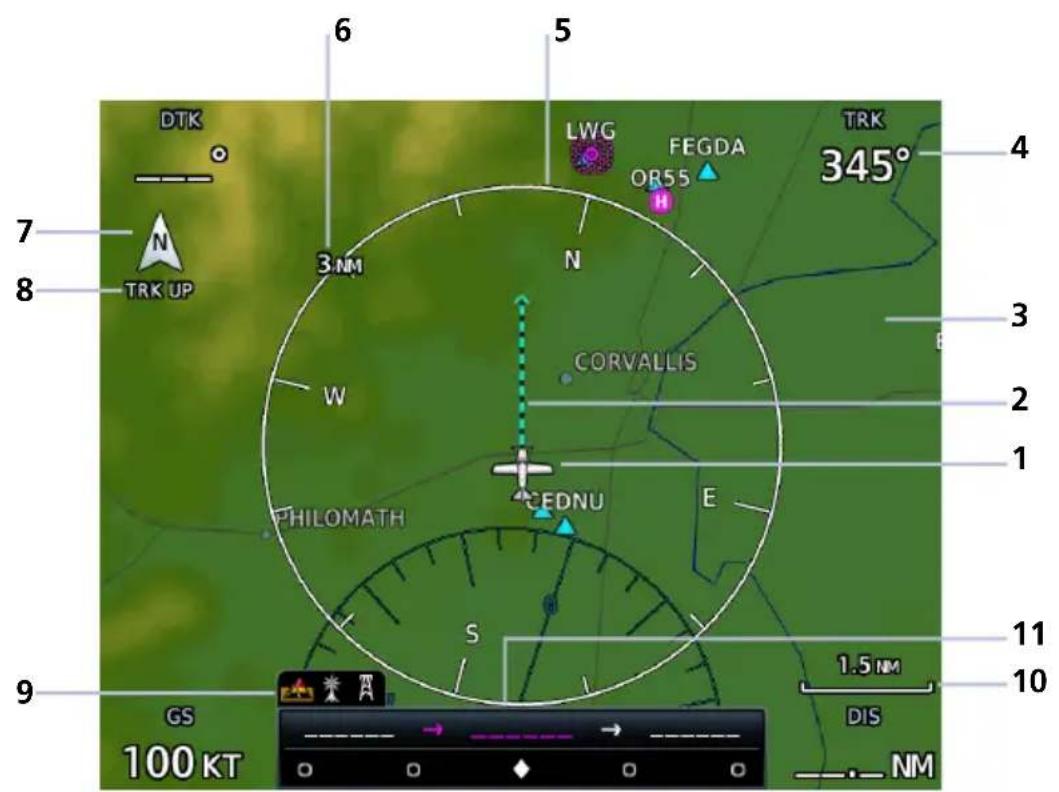
Default Map Features
| 1 | Ownship IconDepicts current aircraft position and orientation. |
| 2 | Track VectorCurrent ground track indication. |
| 3 | BasemapPresents a graphical depiction of land and water data. |
| 4 | User FieldCustomizable data field appearing in each corner of the map. |
| 5 | NAV Range RingDisplays current direction of travel on a rotating compass.Orientation: Magnetic north |
| 6 | Map Range IndicatorDisplays current map range in the upper left quadrant of the range ring (i.e., the distance from the aircraft to the range ring). |
| 7 | North IndicatorIndicates True north. |
| 8 | Map Orientation LabelReflects the selected map orientation. |
| 9 | Map Overlay IconsIndicates status of overlays at the current map range.Includes: obstacles, power lines, precipitation, terrain, and traffic |
| 10 | Zoom ScaleDisplays the current magnification level. |
| 11 | CDI & GPS Nav Status IndicatorLower bar presents a sliding lateral deviation indicator. Upper bar presents from, to, and next waypoints and active leg status annunciations. |
FEATURE LABELS
To maintain readability, map feature labels remain uniform at all zoom levels.
TRAFFIC UNITS
System Units selections do not affect the display of traffic on Map.
LAND AND WATER DEPICTIONS
Land and water data are for general reference only. Data accuracy is not suitable for use as a primary navigation source. The information is intended to supplement and not replace official government charts and notices.
DATA DRAWING ORDER
The electronic map draws data in order of priority, from highest (1) to lowest (36), with higher priority features drawn atop those of lower priority.
| LEVEL FEATURE LEVEL FEATURE | ||
| 1 Traffic 19 County Warning | ||
| 2 Ownership 20 PIREPs | ||
| 3 Flight Plan 21 AIREPs | ||
| 4 TAWS Alerts 22 City Forecast | ||
| 5 Weather Radar 1 | 23 Surface Analysis | |
| 6 Charts 1 | 24 Airspace | |
| 7 Stormscope 25 Waypoints | ||
| 8 Obstacles 26 Airways | ||
| 9 Fuel Range Ring 27 Turbulence | ||
| 10 TFRs 28 Icing Potential | ||
| 11 Freezing Levels 29 Echo Tops | ||
| 12 Cell Movement | 30 NEXRAD | |
| 13 Lightning | 31 Cloud Tops | |
| 14 METARs | 32 IR Satellite | |
| 15 Winds Aloft | 33 SafeTaxi | |
| 16 SIGMETs | 34 Terrain | |
| 17 AIRMETs | 35 Basemap | |
| 18 Cyclone Warn ing | 36 Topo | |
^1 GTN 750Xi Series only.
Map Setup

Overlay data controls reside in the Map menu. Selections are organized into six groups.
Changes to an overlay setting take effect immediately.
Map Setup Menu
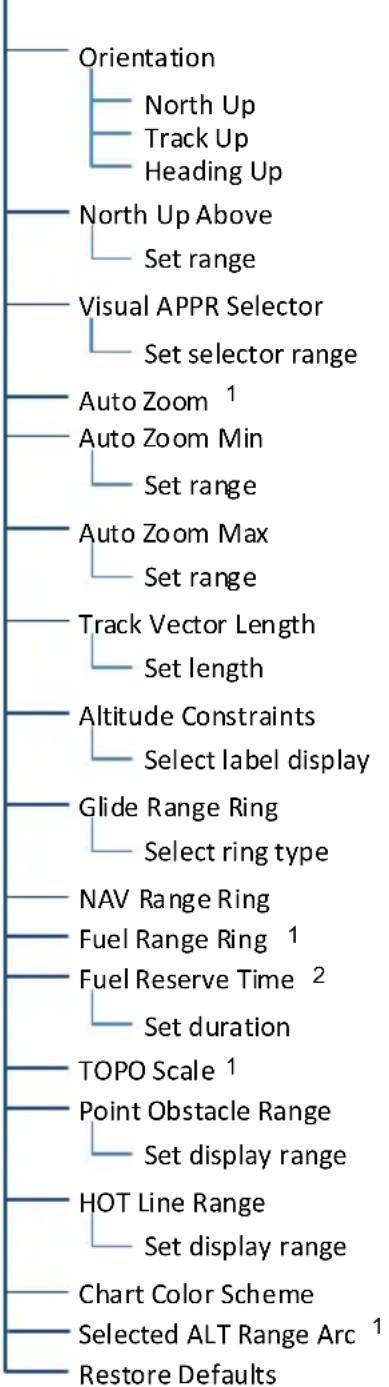
flowchart
graph TD
    A["Orientation"] --> B["North Up"]
    A --> C["Track Up"]
    A --> D["Heading Up"]
    A --> E["North Up Above"]
    E --> F["Set range"]
    A --> G["Visual APPR Selector"]
    G --> H["Set selector range"]
    G --> I["Auto Zoom 1"]
    I --> J["Auto Zoom Min"]
    J --> K["Set range"]
    A --> L["Auto Zoom Max"]
    L --> M["Set range"]
    A --> N["Track Vector Length"]
    N --> O["Set length"]
    A --> P["Altitude Constraints"]
    P --> Q["Select label display"]
    A --> R["Glide Range Ring"]
    R --> S["Select ring type"]
    A --> T["NAV Range Ring"]
    T --> U["Fuel Range Ring 1"]
    T --> V["Fuel Reserve Time 2"]
    V --> W["Set duration"]
    A --> X["TOPO Scale 1"]
    X --> Y["Point Obstacle Range"]
    Y --> Z["Set display range"]
    A --> AA["HOT Line Range"]
    AA --> AB["Set display range"]
    A --> AC["Chart Color Scheme"]
    AC --> AD["Selected ALT Range Arc 1"]
    A --> AE["Restore Defaults"]
RESTORE DEFAULTS
Located in the bottom of each list, this key restores all original factory settings for the active group tab.
Shared Map Settings
Changes to the following map settings also take effect on the configured datalink weather app(s). You may adjust these settings from the appropriate Map Setup tab.
- North Up Above range setting (Map tab)
- Runway Extensions and waypoint display range settings (Aviation tab)
- Road Detail, City Detail, State/Province Names, and River/Lake Detail (Land tab)
Map Display Orientation
Set the orientation of the map display.
Tap Menu > Map Setup > Orientation, and select from the following options.
North Up Track Up Heading Up
Orients map to True north
Orients map to current aircraft GPS track
Orients map to current aircraft heading (requires heading data source interface)
Map orientation label changes to reflect the selected orientation.
Ownership Icon Position & Orientation
• The tip represents actual aircraft location
• Symbol type is dependent upon configuration
- This feature is absent if a GPS source is not available
North Up is useful when zoomed out to view the entire route or a frontal system on a NEXRAD display.
North Up Above
Sets the range at which map orientation changes to North Up.
Using the North Up Above feature causes the screen to switch at certain zoom levels. This is useful as a shortcut to quickly increase situational awareness.
Visual Approach

Visual Approach Key
Sets the distance from the destination airport at which the Visual Approach selector key becomes active.

Auto Zoom
Automatically adjusts Map to display the next waypoint in flight plan at the closest possible map range.

Auto zoom presents SafeTaxi data while aircraft is on ground.
Automatic functionality is overridden during manual zoom interactions. It resumes when:
• Another waypoint is in sequence
- Aircraft transitions from on ground to airborne
• Auto zoom range matches manual override range
Local Auto Zoom (Rotorcraft Only)

Rotorcraft use a local auto zoom function where auto zoom will remain at the 1500 ft zoom scale until the helicopter is above 400 ft GSL or 40 kts.
Set minimum and maximum values to best meet operational needs.
Track Vector
FEATURE LIMITATIONS
- Indication absent when aircraft velocity is < 30kt

Indicates the current ground track.
Arrow tip represents aircraft position at the specified time interval (if the aircraft maintains current ground track during that time).
Track vector length options display as a dashed line and arrow extending from the aircraft icon, showing current track and distance the aircraft will travel in the selected time.
If the track vector is placed over a point on the map, and no data is entered into the system, the unit indicates a wind-corrected GPS track to that point. This is useful for intercepting airways and radials, making small but positive lateral corrections during approaches, and in setting up for arrivals in the terminal area.
Altitude Constraints
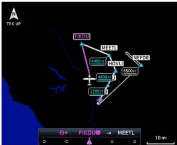
Displays altitude constraint labels within the flight plan.
The active constraint is the altitude to which VNAV is currently providing guidance.
Glide Range Ring
FIXED WING AIRCRAFT ONLY
FEATURE REQUIREMENTS
For best glide performance, the aircraft must be configured in accordance with AFM/POH guidance.
OPTIONAL COMPONENTS
Glide Range Ring wind compensation requires datalink winds or a compatible PFD.

Identifies map region and features within gliding distance. A cyan border indicates where the projected glide descent reaches 50 ft above terrain.
The Glide Range Ring is an estimate based on the best glide speed and glide ratio published for the aircraft. For more information, consult the AFM/POH.
This overlay receives wind information from the ADAHRS (if present). It does not require an ADAHRS unit for operation.
Glide Range Ring Options
Off
Ring Only
Glide Only
Ring and Glide
The Glide Range Ring depicts the estimated glide range down to 50 ft AGL. It does not show beyond 50 ft AGL where the aircraft reaches the ground.
Data updates occur approximately every 5 seconds.
Ring Only Ring and Glide
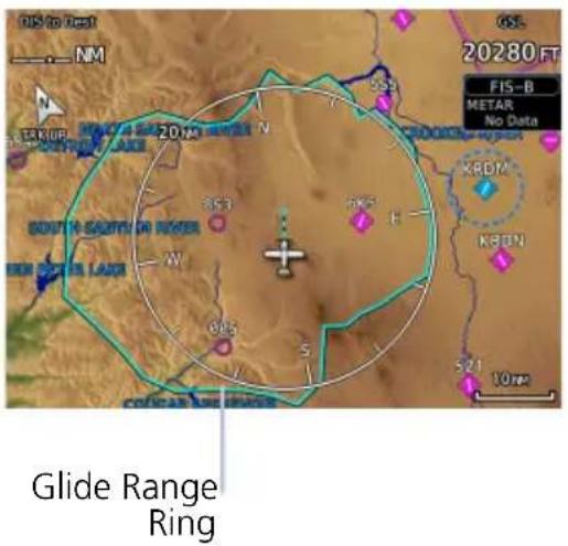

Enable Glide Range Ring to stay aware of all airports within gliding distance. This is extremely helpful should you experience engine failure.
Glide Only
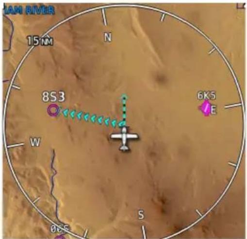
Best Glide Airport Indicator
Cyan arrows point toward the best glide airport at any given time. Best glide airport selection is based on distance from current location, runway length, and weather (if available). Airports beyond the range ring are not considered for routing.
To enable, tap Glide Range Ring and select Ring and Glide or Glide Only.
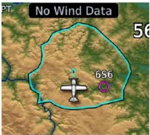
"No Wind Data" Indicator
This indication appears when FMS winds and datalink winds aloft are either unavailable or invalid.
The Glide Range Ring does not adjust to account for current winds when the indicator is present.
No Wind Data
NEAREST AIRPORT GLIDE INDICATIONS
Airports with the "Glide" designation are within line-of-sight of the aircraft and reachable on glide.

The calculated best glide airports appear at the top of the list.
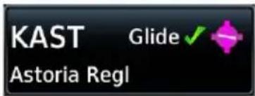
An icon denotes which airports are reachable on glide. Select the identifier to view airport information, including available runways.

Surface type and runway length indications on GTN 650Xi.
Any airports within glide range that do not meet the pilot-specified nearest airport runway criteria may also appear in the list. GTN Xi highlights the offending criteria setting (runway length or surface type) in the APPR/RWY column.

A message appears at the top of the list when no airports are within glide range.
Specify nearest airport runway criteria in the System Setup app. For more about these settings, read Nearest Airport Runway Criteria in section 2.
NAV Range Ring
Provides a more precise indication of distance between the aircraft and map objects.
On Setting Enhanced Setting


Fuel Range Ring
FEATURE REQUIREMENTS
• A Garmin EIS
• Third-party fuel systems

• Estimates the remaining range at the current fuel consumption rate and ground speed.
• Calculations are based on the pilot-specified fuel quantity in the fuel computer
- Dashed green circle indicates selected range to reserve fuel
• Solid yellow circle indicates total endurance range
TOPO Scale

natural_image
Topographic map view showing coastal terrain with river, landmasses, and a small boat, overlaid with a compass rose (no text or symbols on the map itself)Scale Location
Displays a topographical elevation scale. To remove the scale, toggle TOPO Scale off.

Chart Color Scheme
GTN 750Xi SERIES
Toggles chart color scheme between day and night modes.
Day Night
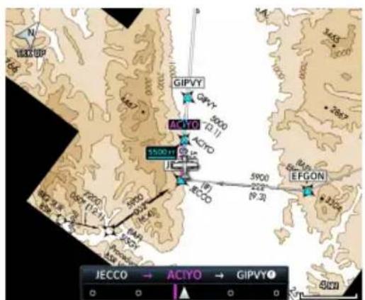
![GIPVY ACIYO 5500km EFGON 5900 224 [9.3] JECCO → ACIYO → GIPVY① 4 km](/content/2026/06/1343935/images/1e8fc10716687d7f7471a684a737f11f70a325767dbedf22f236e57bb434869f.jpg)
Selected Altitude Range Arc
FEATURE REQUIREMENTS
• A Garmin Display Unit

Represents location at which the aircraft is expected to reach selected altitude.
Aviation Selections
Aviation Menu
| Heliports |
| SafeTaxi Diagrams |
| Runway Extensions |
| Intersection Range |
| NDB Range |
| VOR Range |
| VRP Range |
| User Waypoint Range |
| Airway Range |
| TFR |
| Restore Defaults |
Setup options allow you to customize the display of aeronautical information.
- Enable heliports and TFRs
- Specify airway types and range values
- Customize the display of SafeTaxi and waypoint data
- Display runway extensions for a destination airport
With the exception of Heliports and TFRs, all Aviation tab selections provide on/off and range setting options.
The runway feature extends the runway's centerline out 5 NM from the runway threshold. This is useful when setting up for a visual approach, especially at airports with parallel runways or low visibility.
AVIATION DATA SYMBOLS

Non-towered, non-serviced airport ^1

Non-towered, serviced airport ^1

Towered, non-serviced airport ^1

Towered, serviced airport ^1

Soft surface, non-serviced airport

Soft surface, serviced airport

Restricted (private) airport Unknown airport

Heliport ILS/DME or DME only


Intersection LOM


NDB TACAN


VOR VOR/DME


VORTAC VRP


User Airport User Waypoint

Runway extension ATK

SafeTaxi
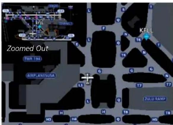
Zoomed In
SafeTaxi provides greater map detail and higher image resolution at lower zoom levels.
Feature labels denote:
- Runways
- Taxiways
- Airport landmarks
SafeTaxi Features
• Airport diagram overlay that includes hot spot information
• Aircraft position relative to taxiways, runways, and airport landmarks
- Pilot selectable range options
SAFETAXI DATA SYMBOLS

Runway Taxiway


Helipad Construction Area

Airport Beacon Unpaved Parking
HOT SPOTS

SafeTaxi hot spots identify locations on an airport surface where positional confusion or runway incursions are likely to occur. These known problem areas require heightened attention by pilots.
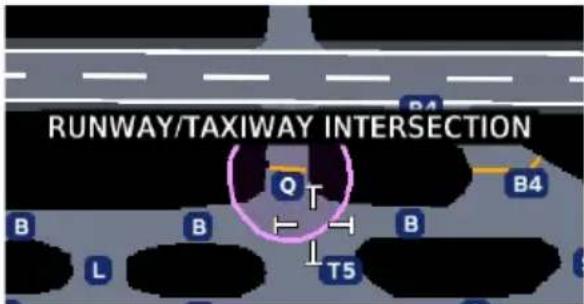
Selecting the border of a hot spot displays a brief summary of the indicated hazard and an information key.

Tapping this key provides additional location information. Numbering corresponds to a list on the airport diagram.

The following airport features may be deemed hot spots by aviation authorities.
• Intersecting taxiways and runways
• Complex ramp areas
• Directional limitations
• Limited wing-tip clearance
• Overflight risk
CONSTRUCTION SPOTS
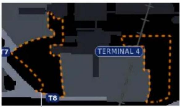
Construction Area Border
There are no expanded detail keys or notes associated with construction areas.
Airspace Selections
Airspace Menu
Airspace Label Range
Smart Airspace
Show Airspaces
Select filter
Class B/TMA/AWY Range
Class C/CTA Range
Class A/D Range
Restricted Range
MOA (Military) Range
Other Range
Restore Defaults
Filter airspace data according to altitude. The control for enabling smart airspace functionality also resides here.
With the exception of Smart Airspace, all Airspace tab selections provide on/off and range setting options.
Smart Airspace
Garmin's Smart Airspace feature automatically de-emphasizes non-pertinent airspace away from the aircraft's current altitude.
Smart Airspace off

When an airspace's vertical proximity to the aircraft is >1,000 ft:
- Its boundary becomes transparent
• All associated altitude labels turn gray
This range increases linearly to 2,000 ft as the aircraft ascends to 10,000 ft.
Smart Airspace on

SMART AIRSPACE CRITERIA
| AIRCRAFT ALTITUDE | AIRSPACE PROXIMITY TO AIRCRAFT1 |
| Sea level >1,000 ft | |
| >10,000 ft 2,000 ft | |
| 1 Vertical distance above and below aircraft altitude. | |
AIRSPACE DATA SYMBOLS
 | Class B Altitude Label (ceiling/floor) |  | Class C/CTA |
 | Class C Altitude Label (ceiling/floor) |  | Class D |
 | Class D Altitude Label (ceiling only) |  | Restricted/Prohibited |
 | TFR MIL |  | |
 | Class B/TMA Other/ADIZ |  |
Land Selections
Land Menu

Filter the display of land features according to detail level.
With the exception of State Province Names, all Land tab selections provide detail setting options.
LAND DATA SYMBOLS

Railroad National Highway

River/Lake Freeway


State/Province Border Small City

Local Road Medium City


Local Highway Large City

Traffic & Weather Selections
TRAFFIC

flowchart
graph TD
    A["Traffic Menu"] --> B["Traffic Range"]
    A --> C["Traffic Type"]
    C --> D["All Traffic"]
    C --> E["Alerts & Advisories"]
    C --> F["Alerts Only"]
Filter traffic data according to type. Other selections include on/off and range setting options.
WEATHER

flowchart
graph TD
    A["Weather Source"] --> B["SiriusXM"]
    B --> C["Cell Movement"]
    B --> D["METAR"]
    B --> E["Echo Tops"]
    B --> F["Lightning"]
    B --> G["Cloud Tops"]
    A --> H["FIS-B"]
    H --> I["METAR"]
    H --> J["Lightning"]
    A --> K["Connext"]
    K --> L["METAR"]
    K --> M["Lightning"]
    K --> N["IR Satellite"]
    K --> O["Connext"]
    K --> P["Settings"]
Setup options are available for all active weather services.
- Specify a datalink weather source
- Toggle individual weather products on/off
Map Interactions
Basic Interactions
Typical map interactions include zoom, pan, and object selection.
PAN & ZOOM
Panning allows movement of the map in any direction without change to the current zoom setting. Zooming adjusts the current magnification level between pre-defined range parameters.
Before flight, consider which map scales are best for achieving the desired level of detail and map information.
Generally, use smaller map scales in and around terminal areas and whenever precise navigation is required (e.g., airway or radial intercepts).
During cruise flight, increase the map scale to better balance navigation, situational awareness, and decision making.
OBJECT SELECTION
Tapping any object or location on the map displays a map pointer and an information banner.
MAP POINTER

This symbol indicates point of contact on the map. A gray circle highlights any selected waypoint or obstacle.
MAP INFO
Available information and controls are dependent upon object or location type and proximity to other objects.
Selecting an airport icon displays the airport's highest field elevation. A map pointer icon corresponds with the touch point on the map.

An information page access key displays when you select a waypoint, airspace, airport, airport surface hot spot, or TFR.

DATA FIELDS CONTROLS
• Pan mode annunciation
- Bearing and distance from current aircraft position to map pointer
- Location elevation
• Maximum altitude AGL and MSL for obstacles
• Map Pointer/Create Waypoint
• Graphical Edit
• Next (for stacked objects)
• Associated information page access key, if applicable
STACKED OBJECTS

To move the selector through each object in proximity of the map pointer, select an object and tap Next.

Overlapping objects may be difficult to identify at a given zoom level.
AIRSPACE INFO
Selected Airspace

When selected, active airspace boundaries change color.
Tapping Airspace Info opens the associated information page.
Airspace Info
MCNARY
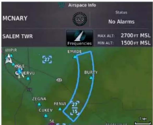
Data fields display information specific to the selected airspace.
GTN 650Xi SERIES
Tapping Preview displays the airspace boundary and a 2D map of the surrounding area.

DATA FIELDS CONTROLS
- Airspace name and type icon
- ATC entity responsible for the airspace, if applicable
• Floor and ceiling altitudes - Proximity to airspace
• Airspace boundary on a 2D map
• Frequencies: View a list of all related radio frequencies
Graphical Flight Plan Editing
FEATURE LIMITATIONS
• Parallel track offsets do not apply to the temporary flight plan

Graphical editing allows quick changes to the active flight plan from the map display.

Map provides identifier keys for selecting waypoints that are stacked or in close proximity.
If the displayed options are not preferred, tap away or select Cancel.
TEMPORARY FLIGHT PLAN BANNER
An information banner displays waypoint selections made during graphical edit mode. All selections become active once you tap Done.
Lists up to five waypoint identifiers

Graphical Flight Plan Mode KSNS → ... → HYP → MOD → LIN → KMHR
Ellipse indicates additional waypoints
Initial waypoint in flight plan always appears first

Tapping Undo reverses the last edit. You may undo up to nine of the most recent actions.
On the map, dragging and releasing the leg away from any waypoints removes it from the temporary flight plan.
To exit edit mode without saving changes, tap Cancel.
ADD WAYPOINT TO AN EXISTING LEG
Existing Leg

You can edit, add, or omit flight plan legs by tapping or dragging your finger directly on the map.
Selected Waypoint

- Tap any location on the map.
- Tap Graphical Edit.
Graphically Edit FPL
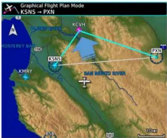
- Tap and drag the leg to a new waypoint or airway, then release.

The temporary flight plan adjusts to show the new route.
If no other edits are necessary, tap Done.


The new waypoint now appears in the active flight plan.
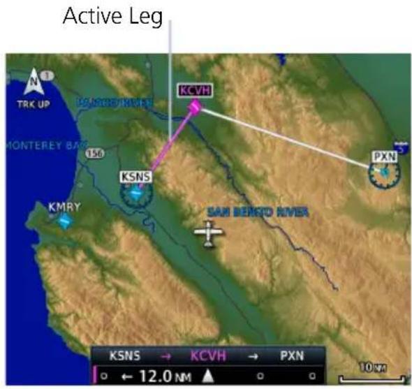
Active route identifiers also appear on the GPS NAV status indicator. If configured, a user field shows active route identifiers on Map.

Delete any existing flight plan before attempting to graphically edit a direct-to waypoint. Map does not allow the addition of an intermediate waypoint between the current position and a direct-to waypoint unless the waypoint is in the flight plan.
REMOVE WAYPOINT FROM FLIGHT PLAN

You can tap and drag any leg to another waypoint or airway, or release it away from any waypoint if an alternate destination is not preferred.

CREATE LEGS WITHOUT AN EXISTING FLIGHT PLAN

Graphical Flight Plan Mode
If an active flight plan does not exist, you can graphically create one without ever leaving Map.
- Tap any location on the map > Graphical Edit.
- Begin tapping waypoints to add them to the temporary flight plan.
- Tap Done.
Map Overlays
Overlay Selections
TOPO
- Charts
- Terrain
- Stormscope
- Traffic
- Airways
- NEXRAD
- Radar
Overlay data controls reside in the Map menu. Changes to an overlay setting take effect immediately.
NEXRAD and Terrain overlays are mutually exclusive. Enabling one automatically disables the other.
Overlay Controls

Control keys enable the specified overlay function only and do not activate interfaced equipment. Control keys remain active even in the absence of required data.
Overlay controls reside in the Map menu.
TOPO

natural_image
Topographic map view showing a coastal region with a marked airport and north arrow (no text or symbols beyond labels)• Overlays topographical data and ground elevation scale
- Depictions are similar to a VFR sectional
- Pilot-selectable topographical elevation scale available
TERRAIN

natural_image
Satellite or aerial view of a coastal region with red terrain, yellow patches, and a white airplane symbol (no readable text or labels)• Overlays terrain map data
- Color shading depicts terrain elevation relative to the aircraft's altitude
TRAFFIC

• Overlays traffic information
- Filter selection on the Traffic page determines altitude range
- Feature optional
NEXRAD

• Overlays datalink precipitation weather information
- Options dependent upon weather data source
- Feature optional
CHARTS

Arrival and departure chart overlays are not available.
• Overlays geo-referenced chart information
- Approach chart for the active flight plan in the navigator
• Airport surface chart if nearest airport is within 200 nm and no approach is active
- Depicts planview area only; excludes inset information (e.g., missed approach procedure view)
- Feature optional

NOTE
In the case of a dual GTN/crossfill configuration, the chart database on each unit must be of the same type and version in order for the correct chart to display on Map.
STORMSCOPE

• Overlays Stormscope lightning information
- Feature optional
AIRWAYS

• Overlays the selected airway type(s) with identifier labels
- Options include: low, high, all, or off (none)
- High altitude airways are green, low altitude airways are gray
RADAR

• Overlays airborne weather radar information
- Depictions are identical to those on the Weather Radar display
• Excludes WATCH shading
- Feature optional
Overlay Status Icons
Icons indicate which overlays are present at the current map range. A crossed out icon means the overlay is active, but data is unavailable due to a failure, test, or standby condition (where relevant).
The absence of an overlay icon means one of two possible conditions:
- Overlay not present at the current detail level or zoom setting.
- Overlay control is off.

Obstacle Power Line


Stormscope Lightning Traffic


Terrain Data not available

User Fields

User fields allow you to customize the display of data in each corner of the map. Tap Change User Fields to access available options.

In configuration mode:
- All four data fields change to selectable keys
- All other map elements are inactive
Tap a key and select from the available data types.
USER FIELD TYPES
Options are organized into three selectable menu tabs:
Data Function Page
Lists available data fields (e.g., distance, bearing, desired track).
Lists available controls. Lists available page access keys. These keys provide direct access to the specified page.


Data Tab Options:
Available field types and their corresponding labels are as follows:
ACTV WPT Active waypoint MSA Minimum safe altitude
| AGL Above ground level NAV/COM Active NAV/COM frequency | 4,7 | |||
| BRG Bearing to waypoint OAT (static) Outside static air temperature | ||||
| D/B APT | Distance/bearing fromdestination airport (i.e., the straight line distance) | OAT (total) | Outside total air temperature | |
| DIS Distance to waypoint | Position Current position (lat/lon) | |||
| DIS toDest | Distance to destination(i.e., the distance alongthe flight plan) | RAD ALT | Height above ground asindicated by the radar altimeter3 | |
| DTK Desired track | TKE | Track angle error | ||
| ESA | En route safe altitude | TRK | Track | |
| ETA | Estimated time of arrival | Time Current time | ||
| ETA at Dest | ETA at destination | Time Current time with seconds | ||
| ETE | Estimated time en route | Time to TOD | Time to top of descent | |
| ETE to Dest | ETE to destination | Trip Timer | Timer display | |
| FLT ID | Flight ID1 | VOR/LOC | Tuned VOR/LOC information4,5,6 | |
| Fuel Flow | Total fuel flow2 | VSR | Vertical speed required | |
| GS | GPS ground speed | Wind | Wind speed and direction | |
| GSL | GPS Altitude | XTK | Cross track error | |
| GenericTimer | Timer display | OFF | Do not display data field | |
"Destination" refers to the missed approach point (if an approach is loaded) or the final airport in the flight plan.
^1 Available when a transponder or GDL 88 is present. ^2 Available when a fuel sensor is present.
^3 Available when a radar altimeter is present. ^4 Label information dependent upon active frequency selection.
^5 Tuned LOC shows airport and runway. Tuned VOR shows radar altimeter and distance to waypoint values.
^b GTN 650Xi and GTN 750Xi units only. ^f GTN 650Xi only.
Function Tab Options:
| CDI key OBS/Suspend/Unsuspend key | |
| DIS/BRG WPT key | On Scene mode key |
| Flap Override key ^1 | MIC PA Mode toggle key ^3 |
| Generic timer controls Playback key | ^3 |
| GPWS Inhibit key ^1 | TAWS/HTAWS Inhibit key |
| G/S Inhibit key ^1 | Weather radar controls ^3 |
| HTAWS RP Mode key ^2 | OFF |
Page Tab Options:
• Active Flight Plan • Approach • Arrival • Backlight • Charts ^3 • Checklist
- Connext Weather • Default Navigation ^4 • Departure • FIS-B Weather
- Fuel Planning • Map • Nearest • Nearest Airport • Procedures
- Scheduled Messages • Services • Sirius XM Weather • Stormscope • Terrain
- Traffic • Trip Planning • Utilities • User Frequencies • VCALC • VNAV
- Waypoint Information • Weather • Weather Radar ^3 • OFF
TOPO SCALE & USER FIELDS
GTN 650Xi SERIES
When active, the topographic scale replaces the bottom left user field.
To view this field, turn off TOPO Scale (Tap Menu > Map Setup > TOPO Scale).
TOPO scale off TOPO scale on
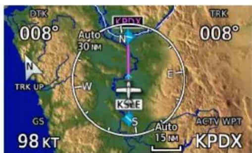
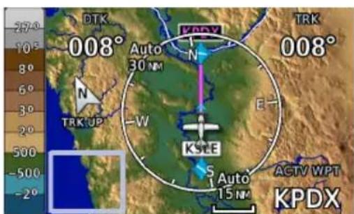
User Field Absent
TURN OFF USER FIELDS

Selecting "OFF" removes the corresponding user field from the map page.

RESTORE DEFAULTS

Tapping this key returns all fields to their default settings.
Default User Fields
• DIS - Distance
• GS - Ground Speed
- DTK - Desired Track
- TRK - Track
- BRG - Bearing ^1
• ETE - Estimated time en route
User fields are useful during time sensitive and work load intense phases of flight.
ADDITIONAL USER FIELDS
Depending on configuration, user fields may be available for display in the control bar. You can access these fields from the System menu.
Home > System > User Fields
GTN 650Xi SERIES
You can also configure user fields for display on the Default Navigation page. Options are identical to those available on Map.
Home > Default NAV > Menu > Configure User Fields

Bottom row user fields allow Data tab selections only.
Tap Map to view and configure user fields on moving map.

Map Detail
Changes to the map detail level take effect immediately. There are four levels from which to choose.
| FEATURE FULL HIGH MEDIUM LOW | ||||
| Small Cities • | ||||
| Medium Cities • | ||||
| Large Cities • | ||||
| Freeways • | ||||
| Highways • | ||||
| Roads • | ||||
| Railroads • | ||||
| Basemap Labels • | ||||
| VORs • • | ||||
| NDBs • • | ||||
| Line Obstacles | • | • | ||
| Point Obstacles | • | • | ||
| Airspaces that are not prohibited or restricted | • | • | ||
| Waypoints | • | • | • | |
| SafeTaxi | • | • | • | |
| Restricted Airspaces | • | • | • | |
| Prohibited Airspaces | • | • | • | |
| Airways | • | • | • | • |
| Active Flight Plan | • | • | • | • |
Present
•
Removed
Charts

The Charts page provides terminal procedures and airport surface diagrams.
FEATURE REQUIREMENTS
• A current and valid chart database
FEATURE LIMITATIONS
- Geo-referencing is not available for some arrival and departure charts
- FliteCharts and ChartView databases are optional and mutually exclusive
Chart Window

Selection Controls
1 Chart 4 Chart Type Selection Keys
2 Airports Selection Key 5 Airport Info Key
3 Charts Selection Key 6 Position Unavailable Icon
CHARTVIEW INFORMATION SECTIONS
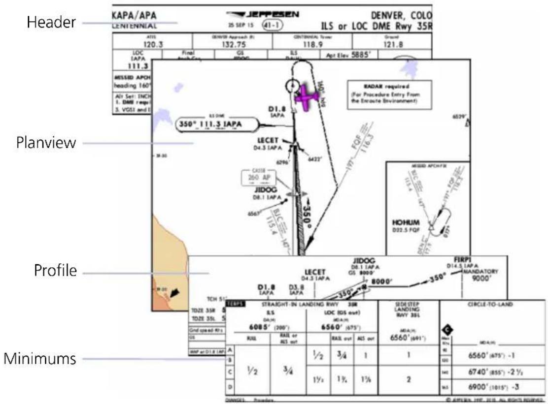
CHART STATUS
Active chart status displays at the bottom of the Charts display.
Getting Newer Charts
Charts Changed
Expired 28-Apr-2016
Not Effective Until 31-Mar-2016
Charts are in the process up updating.
Charts are up to date.
Database is out of date.
Database is installed before it is current.
Chart Setup
Charts Menu

flowchart
graph TD
    A["Chart Information 1"] --> B["All"]
    A --> C["Header"]
    A --> D["Plan"]
    A --> E["Profile"]
    A --> F["Minimums"]
    G["Chart Color Scheme"] --> H["Day"]
    G --> I["Night"]
Tap Menu to access setup selections.
From here you can:
• View individual chart sections (ChartView only)
- Change the chart's color scheme for day or night viewing
Chart Information ^1
Displays individual sections of a chart in theChartView database only. Options include:
• All
- Header
- Planview
- Profile
- Minimums
Invert Colors
Toggles chart color scheme between day and night modes.
• Day mode displays black on white background
• Night mode displays inverse white on black background
Chart Selection

To select a chart:
- Tap Airports.
- Enter an airport identifier.
- Choose from the available chart types.
CHART TYPES

Approach
All approach charts associated with the selected airport. Charts are listed according to level of precision and approach type. Runways are listed in numerical order.

Arrival
Arrival procedure instructions. Arrival charts are listed in alphabetical order.

Departure
Departure route descriptions, including takeoff minimums and obstacle notes.

Information
Airport surface charts, alternate minimums, rate of climb and descent tables, inoperative components or visual aids tables, hot spots, land and hold-short operations, and other destination specific flight data.
Upon selecting a chart type, you have the following options.
- Choose a specific chart: Tap the associated menu key and choose from the list of available charts.
• View airport waypoint information: Tap Airport Info. - Zoom the chart display in or out: Tap In or Out.
AUTOMATIC CHART SELECTION
Automatic chart selection occurs every time the Charts page is opened. The type of chart selected is determined by aircraft status and content from the active flight plan. This function does not override manual chart selections unless a change occurs during one of the following conditions.
| CONDITION CHART DISPLAY DEFAULT | |
| No flight plan or destination airport is present. | Nearest airport diagram. |
| Aircraft is on the ground. | Nearest airport diagram (regardless of flight plan). |
| Flight plan is present, but approach is not loaded. | Airport surface chart for previous airport in flight plan. |
| Approach is loaded in the selected GPS navigator. | Applicable approach chart. |
| No charts are available for a selected airport. | “Chart not available for [airport ID].” |
Aircraft Position Icon
FEATURE REQUIREMENTS
• Aircraft position is fully within chart boundaries
- FliteCharts or ChartView is active (airborne maneuvers only)
FEATURE LIMITATIONS
• SIDs and STARs do not support the display of aircraft position
• Not available for arrival and departure charts
• Displays only within the planview area of geo-referenced approach charts
Aircraft position displays on airport diagrams and approach charts when the current position is known.
POSITION UNAVAILABLE INDICATION

A fault icon appears in the bottom right corner when:
• Aircraft position data is not available
- Selected chart does not contain geo-referenced data
• Selected chart layer is not All or Planview
OFF SCALE AREA

pie
| Segment | Value | |---|---| | MSA | 110 | | SI | 3100 | | 25 | 200 | | NM | 6300 | | 4800 | 4800 | | 50 | 50 |Some charts contain supplemental information within the planview. These areas are considered off scale as they are not geographically accurate.
Aircraft position depictions in off scale areas should be judged relative to the geo-referenced information within the planview only.
Waypoints
There are two types of waypoints: database and user



Database waypoints (i.e., waypoints contained in the navigation database) are organized into the following groups.
- Airport (APT)
- Intersection (INT)
• Very High Frequency Omni-directional Range (VOR)
• Visual Reporting Point (VRP)
• Non-Directional Beacon (NDB)
The Airport page is a great place to start when performing an approach brief, checking weather, or considering a diversion.

You also have the ability to define any point in space and store it. Unlike database waypoints, these "user" waypoints are editable.
Waypoint Information
Dedicated information pages provide waypoint search functions and details not available on Map.
FEATURE REQUIREMENTS
• FIS-B (viewing NOTAMs)
• Navigation database containing VRP waypoint data
FEATURE LIMITATIONS
• FIS-B transmits distant and FDC NOTAMs within 100 nm of radio station position
Intersection, VOR, VRP, and NDB information pages have a uniform layout.

VOR Information Page
| 1 Waypoint Identifier Key 6 Map Preview | |
| 2 Location Information 7 Station Declination | |
| 3 Class Information 8 Nearest NAVAID information | |
| 4 Frequency Selection Key 9 Waypoint coordinates | |
| 5 Waypoi nt Map Symbol 10 Waypoint Distance & Bearing |
Common Page Features
Data Fields Waypoint Identifier
• Distance and bearing from current aircraft position
• Latitude and longitude
- Applicable city, state, country and/or region (e.g., "NW USA")
• Identifier and type icon
This key provides access to multiple waypoint search options. These include the FastFind feature and multiple search tabs.
MAP PREVIEW WINDOW
A 2D map of the surrounding area (includes SafeTaxi airport depictions).

GTN 650Xi SERIES
Tapping Preview displays the waypoint location on a dedicated map page.

As you approach an airport, use the map preview function to orient yourself for such things as pattern entry or runway alignment.
Waypoint Specific Page Features
The following features are unique to the corresponding waypoint.

Airport
Selectable tabs:
Info: Airport location, elevation, time zone, and fuel availability.
Procedures: Available approach procedures.
Runways: Identifiers, size, surface type, and traffic pattern direction.

Tapping Runway opens a list of available runways.
Frequencies: Available communication and localizer frequencies. The "c" symbol denotes frequencies that function as the CTAF.
View additional frequency information by tapping More Information, if available.
WX Data: Applicable METARs, city forecasts, and TAF weather information.
NOTAMs: Applicable distant and FDC NOTAMs.
VRPs: Nearest VRPs.

Intersection
Data fields:
- Nearest VOR (identifier, type icon, bearing, and distance)
Very High Frequency Omni-directional Range
Frequency: Loads the indicated value as the COM or NAV frequency.
Data fields:
- Frequency
- Nearest airport (identifier, type icon, bearing, and distance)
- Station declination
• VOR class

Visual Reporting Point
Data fields:
- Nearest VRP (identifier, type icon, bearing, and distance)

Non-Directional Beacon
Data fields:
- Frequency
- Nearest airport (identifier, type icon, bearing, and distance)
- Marker description

User Waypoint
Selectable functions:
Edit: Opens the Create User Waypoint page for editing purposes.
View List: Displays a list of all user waypoint identifiers.
Delete: Removes the selected user waypoint from the list.
Delete All: Removes all user waypoints from the list.
All deletions require user confirmation.
User waypoints in the active flight plan cannot be edited or deleted.
Data fields:
- Reference position or nearest waypoint (identifier, type icon, radial, and distance), whichever is applicable
• Number of waypoints used out of 1,000
The User WPT page is the only page that allows you to view an entire list of all user waypoints created and saved in the database.
Waypoint Selection

The Waypoint Identifier key provides access to different waypoint search options.
Enter a specific identifier or select one from the available search tabs.
Waypoint Autofill

As you type the identifier name, alphanumeric characters autofill based on the first alphabetical match in the navigation database.
Autofill characters are cyan and display from the cursor position to the right of the field.
Matching waypoint entries typically change with the addition of each typed character.
"No matches found" and "Duplicates found" annunciate when applicable.
FastFind Predictive Waypoint Entry

FastFind predicts a waypoint based on the characters you select. As you type, the key label changes to reflect the identifier of the nearest matching entry.
Tap to select the predicted waypoint and open the corresponding information page.
Because it relies on your GPS position, FastFind can make predictions based on a single key press.

If no matches are found, "No suggestion" annunciates and the key is not selectable.

FastFind & Flight Plan
For convenience, use FastFind when creating your flight plan. GTN will search for waypoints closest to the current GPS position.
- If inserting a waypoint in the middle of the flight plan, GTN searches for waypoints between the next and previous waypoints.
- If adding a waypoint to the end, GTN searches for waypoints closest to the last waypoint in the flight plan.
FastFind is a convenient shortcut when you are adding waypoints to a flight plan or trying to find a waypoint in a hurry.
Search Tabs

The Find key provides access to multiple search tabs.

Each tab displays a list of selectable identifiers based on specific criteria. These include:
- Recent
- Nearest
- Flight Plan
- User
- Search Name
- Search City
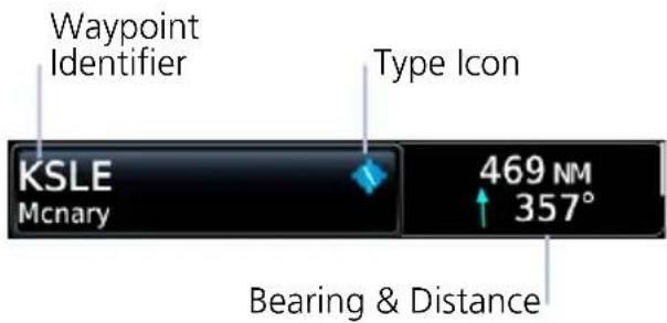
Each entry includes general information about the associated waypoint.
RECENT
Lists up to 20 of the most recently viewed waypoints.
NEAREST
Lists up to 25 waypoints within a 200 nm radius.

Tap Filter and select from the available filter options. Only waypoints belonging to the selected class appear in the list. To list all classes, select All.
FLIGHT PLAN
Lists all waypoints contained in the active flight plan.
USER
Lists up to 1,000 user-defined waypoints.
SEARCH BY NAME/CITY

Search By Name
Lists all airports, NDBs, and VORs associated with the specified facility name.
Tap Search Facility Name to begin search.

Search By City
Lists all airports, NDBs, and VORs found in proximity of the city.
Tap Search City Name to begin search.
Create User Waypoints
Create and store up to 1,000 user defined waypoints.
FEATURE LIMITATIONS
• Duplicate user waypoint identifiers are not allowed
- Names may be up to six characters in length
• Comment may be up to 25 characters
• Maximum waypoint limit: 1,000
WHERE TO FIND IT

flowchart
graph TD
    A["Home"] --> B["Waypoint Info"]
    B --> C["Create WPT"]
You may access this page from the following applications:
- Waypoint Info
- Map
MAP POINTER/CREATE WAYPOINT KEY
Tapping any location on Map that is not an existing waypoint displays this page access key.
USER WAYPOINT IDENTIFIER
Assign a unique identifier or keep the unit generated identifier. If an identifier is already in use, the three digit number increments automatically upon opening the page.

User Waypoint
By default, the identifier format is "USR" followed by a sequential three digit number.
User Airport
Identifier format is "A" followed by a sequential three digit number.
User waypoints are helpful when ATC requests that you fly one radial to intercept another. While the point is often defined by an intersection in the navigation database, this is not always the case. The Create User Waypoint function allows you to define the new intersection and insert it into the flight plan in advance, as opposed to using the NAV radio to tune each VOR and specify the radials to fly inbound and outbound.
Define Waypoint Criteria

flowchart
graph TD
    A["Create Waypoint Options"] --> B["User Identifier"]
    B --> C["Specify identifier"]
    B --> D["Airport"]
    D --> E["Specify elevation"]
    D --> F["Comment"]
    F --> G["Type comment"]
    F --> H["Position"]
    H --> I["Radial/Radial\nRadial/Distance\nLAT/LON"]
    H --> J["Graphical Edit"]
    J --> K["Temporary"]
    J --> L["Create"]
Active user waypoints already existing in a flight plan are not editable.
When creating a user waypoint, you have the option to:
- Assign a unique identifier
- Set the waypoint as temporary
- Enter a comment
- Set waypoint position
- Specify elevation (user airports only)
• Edit the waypoint graphically
| User Identifier | Assign a unique identifier. |
| Airport | Label the user waypoint as a user airport |
| Comment | Type a comment regarding the new waypoint. |
| Position | Set the waypoint position. |
| Graphical Edit | Open a preview map for graphical editing purposes. User waypoint icon remains stationary as you move the surrounding map to the new location. |
| Temporary | Assign the waypoint a temporary status. Identifier remains available until the next unit power cycle. |
| Elevation | Specify the elevation of the user airport. Available only when the Airport key is active. |
| Create | Add the new identifier to the used waypoints list. The associated information page opens automatically for viewing and editing purposes. |
COMMENT FORMAT
Default comments display in a specific format for each reference type.
LAT/LON Radial/Distance

Radial/Radial

POSITION TYPE
Set the waypoint position type using one of the following options.
Radial/Radial Radial/Distance LAT/LON
Specify a waypoint and radial for each of the two reference points.
Specify the reference waypoint, radial, and distance.
Specify the point's latitude and longitude.
MARK WAYPOINTS
Installations equipped with an external Mark on Target (MOT) switch allow immediate user waypoint creation by marking the point in space at which the switch is activated.
These waypoints contain a unique identifier with a sequential three digit number ("MOT###") that increments with every push of the MOT switch. If the number exceeds 999, the counter resets and begins to overwrite identifiers at the beginning of the list.
Upon marking a target with an MOT switch, the waypoint may be obscured by the ownership and not readily visible. In such cases, you may verify waypoint creation by changing the map zoom level or viewing the User Waypoints page.
Create a User Waypoint
OPEN CREATE USER WAYPOINT PAGE
From Map:
Home > Map > select any non-waypoint location > Map Pointer/Create Waypoint
From Waypoint Info:
Home > Waypoint Info > Create Waypoint
ASSIGN POSITION VALUES
From the Create User Waypoint page:
- Tap Position > LAT/LON > Latitude/Longitude > specify the waypoint's coordinates > Create.
OR
-
Hold and drag the basemap until the user waypoint icon appears over the desired location.
-
Tap Create.
MODIFY DEFAULT SETTINGS
Modify default settings as necessary.
• Create a custom identifier: Tap User Identifier and enter a new one.
- Add a comment: Tap Comment and enter the appropriate text.
- If the waypoint is an airport: Tap Airport > Elevation, then specify the number of feet.
• If the waypoint is for temporary use: Tap Temporary.
Once all modifications are complete, tap Create.
Edit an Existing User Waypoint
FEATURE LIMITATIONS
- User waypoints that are part of a flight plan or direct course are not editable
ACCESS USER WAYPOINT EDIT OPTIONS
You can access the edit function multiple ways.
From the dedicated information page:
Home > Waypoint Info > User WPT > specify an identifier, or tap View List and select an identifier from the used waypoints list > Edit
From the Nearest page:
Home > Nearest > User WPT > select an identifier from the list (e.g., USR001) > Edit
From the Active FPL page:
Home > Flight Plan > select the identifier from the flight plan > Waypoint Info > Edit
MODIFY POSITION VALUES
From the Edit WPT page, you can modify a user waypoint's position one of two ways:
- Tap Position > LAT/LON > Latitude/Longitude > specify the waypoint's coordinates > Save.
OR
- Hold and drag the basemap until the user waypoint icon appears over the desired location.
- Tap Save.
Delete User Waypoints
FEATURE LIMITATIONS
- User waypoints that are part of a flight plan or direct course cannot be deleted

You can delete a user waypoint from its information page:
-
Select the user waypoint, then tap Delete.
-
Confirm the request.
DELETE ALL USER WAYPOINTS

From the User Waypoints list, you can delete all user waypoints or filter the list and delete only a certain type.
This list is accessible from the information page.
-
Tap View List > Menu.
-
Tap Filter and select the type of user waypoints you wish to delete. Options include All, Basic, and Airport.
-
Tap Delete All.
Import User Waypoints

The Import Waypoints key appears when the unit detects a user waypoint on the datacard.

NOTE
The import function overwrites any existing user waypoint of the same name.
FUNCTIONAL LIMITATIONS
- User waypoint file size must not exceed 8 GB
CREATE USER WAYPOINT FILE
You may create a list of new user waypoints using any spreadsheet program. Read User Waypoint File Considerations for limitations and formatting specifications. Organize columns as follows.
ABCD
Waypoint Name Comment Latitude Longitude
User Waypoint File
| A | B | C | D | |
| 1 | MTHOOD | MT HOOD PEAK | 45.3723 | -121.69783 |
| 2 | CRTRLK | CRATER LAKE | 42.94683 | -122.11083 |
| 3 | EIFEL | EIFEL TOWER | 48.858151 | 2.294384 |
| 4 | OCEAN | 32.68735672 | -51.45543634 |
User Waypoint File Considerations
- Limit one waypoint per row
- Names may be up to six characters in length
• Comments may be up to 25 characters
• All letters must be upper case
• Latitude: two digits left of decimal; up to nine digits right of decimal - Longitude: three digits left of decimal; up to eight digits right of decimal
- (-) indicates southern latitudes (column C) or western longitudes
• Express latitude and longitude coordinates in decimal degrees
Save the file in the .csv format under the name "user.csv." Change the file extension to ".wpt" before copying the file to a blank SD card.
IMPORT USER WAYPOINTS
- Ensure that the unit power is off.
- Insert datacard containing user waypoints.
- Power on unit.
- From the Home page, tap Waypoint Info > Import Waypoints.
- Acknowledge the pop-up message.
The import function executes in the background. Once the import is complete, an advisory message informs: "User waypoints were imported successfully."
The waypoints are now available for use. You may power down the unit and remove the SD card.
If an imported waypoint is within 0.0001 degree (latitude and longitude) of an existing user waypoint, the existing waypoint and name will remain in use.
Nearest
View a list of the nearest waypoints, frequencies, or facilities within 200 nm of the aircraft's position.
From the Home page:
- Tap Nearest and then select a waypoint or frequency icon.
- Scroll through the list of entries.
Information varies according to the selected waypoint or frequency type. Nearest waypoints provide an identifier key for accessing the associated information page.

Nearest Airport
- identifier • symbol • distance • bearing • approach type
• length of longest runway

Nearest Intersection
- identifier • symbol • distance • bearing

Nearest Very High Frequency Omni-directional Range
- identifier • symbol • distance • bearing • frequency

Nearest Visual Reporting Point
- identifier • symbol • distance • bearing

Nearest Non-Directional Beacon
- identifier • symbol • distance • bearing • frequency

Nearest User Waypoint
- identifier • symbol • distance • bearing

Nearest Airspace
- identifier • symbol • proximity

Nearest Air Route Traffic Control Center
- facility name • distance • bearing • frequency
Nearest Flight Service Station
- facility name • distance • bearing • frequency (“RX” denotes receive-only frequencies)

Nearest Weather Frequency
- facility name • distance • bearing
• frequency of nearest ATIS, ASOS, AWOS, and VOR
ENTRY LIMITS
| NEAREST LIST | ENTRY LIMIT |
| ARTCC, FSS 05 | |
| Airspace 20 | |
| Airport, Intersection, VOR, VRP, NDB, User, Weather FREQ | 25 |
The number of entries displayed varies according to item type.
Entries are ordered from closest to farthest.
UPDATE INTERVALS
With the exception of nearest airspace, all lists update every 30 seconds. The nearest airspace list updates once per second.
MULTIPLE FREQUENCIES
This key displays when more than one frequency is available at the indicated range.
Applicable to functions displaying information only (ARTCC, FSS, and WX FREQ).
Active Flight Plan

Current flight plan information displays as a scrolling list on the Active Flight Plan (FPL) app.
FEATURE REQUIREMENTS
• Active flight plan
FEATURE LIMITATIONS
• Displays up to 99 waypoints for an active flight plan

Active Flight Plan
| 1 | Selectable Data Field Columns | 5 Current Waypoint |
| 2 | Waypoint Identifier Column 6 | Waypoint Type Icon |
| 3 | Procedure Header 7 Leg Data | |
| 4 | Active Leg Indicator 8 | Airport Info Key |
AIRPORT INFO


For convenience, airport information is directly accessible from the procedure header. This includes airports specified in active approaches, arrivals, and departures.
Tap Airport Info to open the corresponding information page.
FIX TYPE INDICATIONS
| LABEL FIX TYPE |
| iaf Initial Approach Fix |
| faf Final Approach Fix |
| map Missed Approach Point |
| mahp Missed Approach Hold Point |
| -p Parallel Track (no fix) |
When applicable, labels indicate the fix type associated with an identifier.
ACTIVE LEG STATUS INDICATIONS
Magenta symbols denote active leg status on from/to/next waypoint indications. Fix type symbols (e.g., FAF, MAP) correspond with labels appearing on the flight plan.
 | IAF Arc Left |  | |
 | FAF |  | Holding Pattern (Right Turns) |
 | MAP |  | Holding Pattern (Left Turns) |
 | MAHP Active Leg Arrow |  | |
 | Parallel Track Direct To |  | |
 | Arc Right |
Create a Flight Plan

NOTE
The unit cannot verify the accuracy of cataloged flight plans with modified procedures.
There are three methods for creating a new flight plan.
CREATE FROM THE ACTIVE FLIGHT PLAN PAGE
- Tap Flight Plan.
- Delete the existing flight plan if necessary (Menu > Delete).
- Tap Add Waypoint.
- Select an identifier using the provided search options.
- Repeat steps 3 - 4 for each waypoint in the route.
CREATE FROM MAP
Build a flight plan by selecting waypoints directly on the map using Map's Graphical Flight Plan mode.
CREATE FROM THE FLIGHT PLAN CATALOG
- Tap Flight Plan > Menu > Catalog.
- Scroll to the end of the flight plan list.
- Tap Create New Catalog Route > Add Waypoint.
- Add waypoints using the provided search options.
- Tap Menu > Preview > Store or ACTV (Activate).
As a general practice, never save flight plans with modified procedures in the catalog.
Airway Options
Airway Options
flowchart
graph TD
    A["Collapse All Airways"] --> B["Select Airway"]
    B --> C["Remove Airway"]
Selecting an airway from the active flight plan opens a menu. You may elect to:
• Collapse all legs of the airway
- Select a new airway
- Remove an airway from the flight plan
Collapse All Airways
Airways automatically display as flight plan legs. A single airway may contain numerous legs. Airways without an active leg collapse for simplification. This does not affect airway legs shown on the external navigator(s).

All airways begin with an indicator field and end with an exit identifier.
To hide all waypoints along an airway, but not the airway's exit waypoint, tap Collapse All Airways.
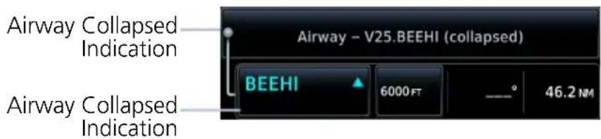
Sort Airways
Preview of a sorted airway waypoint list.
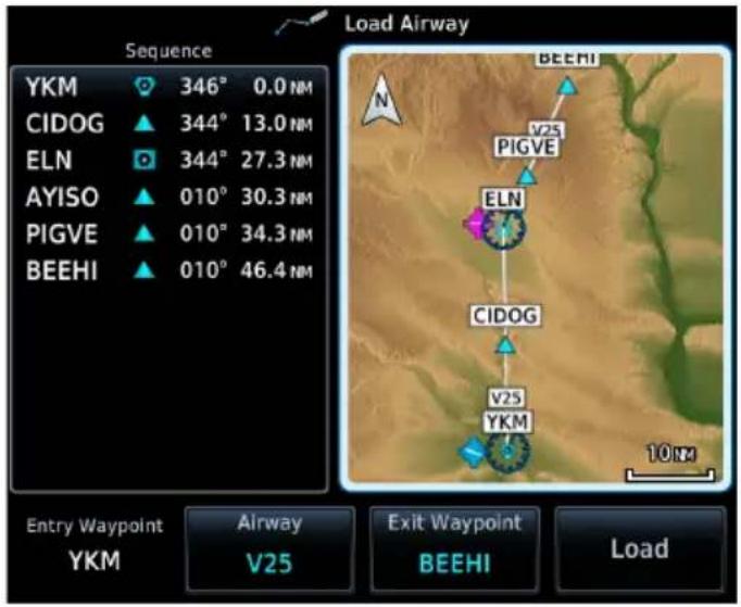
A toggle key allows you to sort the airway waypoint list alphabetically or by distance.
This option is available once you select an airway.

The sort function is useful when you are searching for an exit point from the airway.
En Route Vertical Navigation

Create a vertical navigation (VNAV) path with multiple altitude constraints in the flight plan.

WARNING
Do not rely solely on VNAV guidance when navigating horizontally and vertically around user-defined airports. It is the pilot's responsibility to ensure separation from terrain and obstacles during an approach to a user-defined airport.
FEATURE REQUIREMENTS
- Enablement by the installer
• Baro-corrected altitude source
FEATURE LIMITATIONS
The following flight plan waypoints do not allow altitude constraints:
• Legs containing headings
- Legs that terminate at an altitude (e.g., a climb to 1,800 ft before making a turn and proceeding direct to fix)
Storing a flight plan in the catalog removes its altitude constraints.
WHERE TO FIND IT

flowchart
graph TD
    A["Home"] --> B["Utilities"]
    B --> C["VNAV"]
The vertical navigation (VNAV) feature provides vertical profile guidance during the descent phase of flight. Guidance is based on altitude constraints associated with lateral waypoints in the active flight plan.
This feature is also accessible via the Active Flight Plan menu (Home > Flight Plan > Menu > VNAV).
Annunciations display within 60 seconds of the top or bottom of descent. A "Vertical Track" aural message plays at 60 seconds from the top of descent.
VNAV Functions
- Presents vertical path guidance along the descent as either a line joining two waypoints with specified altitudes or a desired linear vertical path (i.e., the vertical angle from the specified waypoint or altitude)
• Integrates vertical waypoints into the active flight plan
• Supports both manual and autopilot coupling
For installation details related to en route vertical navigation, consult the AFMS.
Define a VNAV Profile

Active vertical navigation profile information displays on the VNAV Profile page. From here you can:
- Enable en route vertical guidance
- Specify a target vertical speed and flight path angle
• View active constraint data - Set a default FPA (in the VNAV Profile menu)
VS Target and FPA may be unavailable if the selected altitude is set higher than the Active VNAV Constraint or if the aircraft is more than 50 NM from the top of descent.
ENABLE VNAV GUIDANCE
From the active flight plan:
Home > Flight Plan > Menu > VNAV > VNAV Enabled.
Tapping VNAV again toggles the function off.
Disabling vertical navigation:
- Invalidates required vertical speed, time to TOD/BOD, and vertical deviation data
- Removes vertical deviation and required vertical speed indications from the PFD
VNAV automatically re-enables when you initiate a direct course.
Altitude Constraints
Altitude constraints are either entered manually into the active flight plan, or automatically retrieved from the published altitudes in the navigation database. GTN automatically uses altitudes loaded with arrival and approach procedures (up to and including the FAF) for computing vertical deviation guidance.
Altitude constraints loaded from the database are jet altitudes. Some adjustment may be necessary for other types of aircraft. For the adjustment procedure, refer to the published chart.
ALTITUDE CONSTRAINT INDICATIONS
| COLOR DEFINITIONS | |
| White Altitude is for reference only. | |
| Cyan | GTN honors the constraint for vertical guidance when the VNAV function is active. |
When the VNAV function is active, altitudes may be accompanied by one or two altitude restriction bars. The position of the value (above or below the bar, or between two bars) denotes the required aircraft altitude relative to that constraint.
Dual values annunciate when the aircraft needs to cross between two altitudes. Constraint values display in MSL or flight level (FL). Constraints at airports may be specified as MSL or AGL.
Examples:
Cross at or Above 5,000 ft

Cross at 5,000 ft

Cross at or Below 5,000 ft

Cross Between 5,000 ft and 6,000 ft
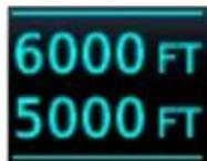
| ALTITUDE TYPES | |
 | Database ConstraintAltitude is retrieved from the navigation database and designated for use in determining vertical guidance. |
 | Pilot-specified ConstraintPencil icon indicates manual designation or manual data entry. |
 | Invalid Altitude ConstraintGTN cannot use the altitude to determine vertical guidance. |
| Estimated Crossing Altitude | |
 | For reference only.System calculated estimate of aircraft altitude as it passes over the navigation point. Absence of bar(s) indicates it is not a potential constraint. |
| Published Reference Altitude | |
 | For reference only.Altitude is retrieved from the navigation database, but not for use in determining vertical guidance. Bar above and/or below the value indicates constraint type. |
Altitude Constraint Data Priority
GTN prioritizes altitude constraint data for each navigation point and displays it in the ALT column of the active flight plan.
- GTN honored constraints (includes invalid constraints)
- Reference-only estimated crossing altitudes
- Published reference altitudes
- Empty (no altitude data)
INVALID ALTITUDE CONSTRAINTS
An altitude constraint is invalid if:
• Meeting the constraint requires the aircraft to climb
- Meeting the constraint requires the aircraft to exceed the maximum flight path angle (6° downward) or maximum vertical speed (-4,000 fpm)
• It results in a TOD behind the aircraft's current position
- It is within a leg type that does not support altitude constraints
• It is added to a waypoint past the FAF
ALTITUDE CONSTRAINT OPTIONS
Once added to the flight plan, an altitude constraint may be modified or deleted using the controls in the VNAV Options menu. Select a value in the ALT column to display available options.
| Type | Opens a list of available constraint typesOptions: At, At or Above, At or Below, and Between |
| Altitude Data Entry | Opens a keypad. Specify an altitude value for the selected constraint typeUnit options: MSL, AGL, and Flight Level |
| Revert Constraint | Returns a modified altitude constraint to its original polished value |
| Remove Constraint | Removes the VNAV designation from the altitudeValue remains displayed for reference purposes. It is no longer used to compute vertical guidanceRemoving the VNAV designation from an altitude may invalidate other displayed altitudes or cause them to change after recalculation |
Designate a waypoint altitude for use with vertical guidance:
- Select a waypoint altitude constraint.
- Tap Save.
Enter or modify an altitude constraint:
- Select an altitude constraint.
- Tap Type and select the constraint type.
- Select the altitude data key.
- Enter an altitude constraint value using the keypad.
- Select altitude units.
- Tap Enter to accept the altitude.
- Tap Save.
Delete an altitude constraint:
- Select an altitude constraint.
- Tap Remove Constraint.
- Tap OK.
Return a modified altitude constraint to its original database value:
- Select an altitude constraint containing the pencil icon.
- Tap Revert Constraint.
- Tap OK.
VNAV Direct To

This function creates a vertical navigation path from the aircraft's current position and altitude to a selected waypoint's location and altitude.
By removing any VNAV constraints between the aircraft and selected waypoint, it allows you to fly the lateral flight plan in a continuous descent and reach the waypoint at the specified altitude.
ACTIVATE VNAV DIRECT TO
- Select an altitude constraint.
- Tap VNAV Direct To.
- Confirm the request.
Transition to Approach
FEATURE LIMITATIONS
• Function availability dependent upon installer configuration
VNAV responds differently based on approach type.
| VNAV APPROACH RESPONSE | |
| Transition to Approach enabled | Vertical path attempts a smooth transition from en route to approach vertical guidanceAircraft intercepts with approach guidance from below the glidepath/glideslope |
| Transition to Approach not enabled | En route VNAV terminates at the waypoint prior to the FAF on approaches with vertical guidanceEn route VNAV terminates at the FAF (LNAV only) |
For more information about the transition to approach function, consult the AFMS.
Temperature Compensated Altitude

NOTE
GTN and TXi displays use a single destination airport temperature for calculating compensated altitudes. Changing the temperature on one of these units automatically recalculates the value across all connected GTNs and GDUs.
FEATURE REQUIREMENTS
• Active flight plan contains a destination airport
• GDU 700()/1060 for access via PFD Minimums menu
Calculate loaded approach altitudes based on the pilot-specified destination temperature. Once you enter the destination temperature, GTN increases the approach altitudes accordingly.
SETTING TEMPERATURE COMPENSATED ALTITUDE
Controls for setting temperature compensation are accessible from two places:
• Active Flight Plan menu
• Minimums menu (PFD only)

Snowflake icon indicates temperature compensated FAF altitude.
To toggle function on or off, tap Temperature Compensation.
ACTIVATE TEMPERATURE COMPENSATED ALTITUDE
From the active flight plan:
Tap Menu > Temperature COMP > Temperature Compensation > TEMP at DEST, and specify the destination airport temperature.
The temperature compensated FAF altitude annunciates in magenta.
OBS

The Omni Bearing Selector (OBS) allows you to select between manual or automatic sequencing of waypoints.

When active, this function allows you to set the desired course To/From a waypoint using the provided controls or with an external OBS selector on HSI or CDI.
- Tap OBS.
- Specify a heading course.
OBS Mode

CDI indicates the OBS heading. The mode displays on the annunciator bar.
The unit retains the active To waypoint as a navigation reference even after passing the waypoint (i.e., prevents sequencing to the next waypoint).
Tapping the key again resumes automatic sequencing of waypoints (normal mode).
SUSPEND/UNSUSPEND

SUSP
This key displays for leg types that do not support OBS.

UNSUSP
This key displays for legs that auto suspend (e.g., leg holds, missed approaches).
Dead Reckoning

WARNING
Do not use projected position data as the only means of navigation.
Points About Dead Reckoning
- Provides limited navigation using the last known position and speed following the loss of GPS navigation while on an active flight plan
- Becomes active after a loss of GPS position while navigating using an active flight plan and the flight phase is either En Route or Oceanic
- Allowed only during en route and oceanic phases of flight
When dead reckoning mode is active:
• System flags all external outputs dependent upon GPS position data
- Map reports "No GPS Position"; overlays are not available
- "DR" appears over the ownership icon
• DR mode annunciation replaces ENR or OCN
- Terrain functionality is not available
• Traffic and Stormscope data display on their respective pages only
• CDI is not available
Dead Reckoning Mode, GTN 650Xi
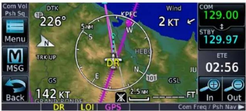
Dead reckoning mode ends once GPS position is restored.
Parallel Track

Create a parallel course offset relative to the current flight plan. Setup controls provide offset distance and direction setting (left of track or right of track).
FEATURE REQUIREMENTS
• An active flight plan
FEATURE LIMITATIONS
• Function not available when Direct-to is active.
• Graphical editing of the active leg cancels the parallel track function
- Offset range: 1 nm to 99 nm
- Large offset values combined with certain leg types (e.g., approach) or leg geometries (i.e., changes in track >120^ ) do not support parallel track
| TRACK COLOR |
| Offset Magenta |
| Original Gray |
Once activated, a new track line appears to the left or right of the original course line at the specified distance. The aircraft navigates to the offset track with external CDI/HSI guidance now driven from the parallel track.

A graphical depiction overlays on the map.

Corresponding fix symbols on the flight plan indicate when the active leg is on a parallel track.
Active route identifiers also appear on the GPS NAV Status bar.

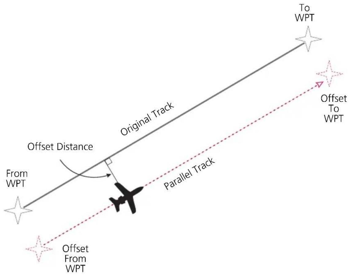
ACTIVATE A PARALLEL TRACK
- Tap Menu > Parallel Track.
- Tap Offset and specify a distance between 1 nm and 99 nm.
- Tap Direction and select left of track or right of track.
- Tap Activate.
To deactivate parallel track, tap Menu > Remove PTK.
Invert Flight Plan
Reverse the active flight plan and use it for navigation guidance back to your original departure point. Inverting the flight plan does not affect the original version stored in the catalog.
Be aware that inverting a flight plan removes all ATKs.
INVERT THE ACTIVE FLIGHT PLAN
Tap Menu > Invert.
Edit Data Fields
This function allows you to change the data type for any flight plan column. By default, flight plan displays:
- ALT - DTK - DIS
| DATA FIELD SELECTIONS | |
| ALT Altitude Constraint | |
| CUM Cumulative Distance | |
| DIS Distance | |
| DTK Desired Track | |
| ESA En Route Safe Altitude | |
| ETA Est. Time of Arrival | |
| ETE Est. Time En Route |
Selections are identical for each data field.
GTN 750Xi SERIES
Data field columns are arranged in numerical order (1 - 3).

CHANGE DATA FIELD TYPE
- Tap Menu > Edit Data Fields.
- Tap any column/field and select a data type.
To restore data fields to their default settings, tap Restore Defaults.
Flight Plan Catalog

Create, activate, edit, copy, and delete flight plans within the catalog.
FEATURE LIMITATIONS
• Stores up to 99 flight plans with a maximum of 100 waypoints each

Each catalog entry includes the identifiers of the departure and destination waypoints. These comprise the route identifier.
GTN 750Xi SERIES
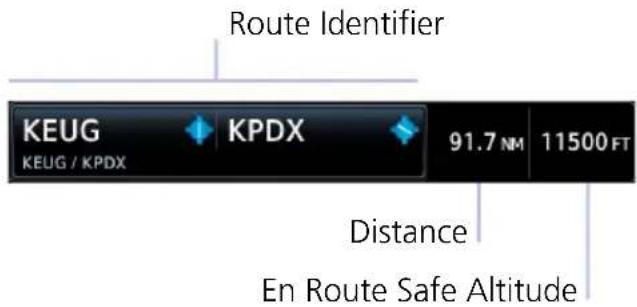
In addition to the route identifier, these units display the route distance and en route safe altitude.
Catalog Route Options
Route Options

flowchart
graph TD
    A["Delete"] --> B["Copy"]
    B --> C["Edit"]
    C --> D["Preview"]
    D --> E["Invert & Activate"]
    E --> F["Activate"]
Selecting a flight plan opens a menu. Changes to the active flight plan take effect immediately.
• Activate the selected flight plan (replacing the active flight plan)
• Reverse and activate the selected flight plan
• Preview a selected flight plan
• Make changes to a flight plan
- Copy the flight plan and modify it to create a similar one
- Remove individual or multiple flight plans
ACTIVATE
Activating a stored flight plan overwrites the active flight plan.
INVERT & ACTIVATE
Reverse and activate the selected flight plan for guidance back to your original departure point. The inverted flight plan is a copy. Changes do not affect the original flight plan, which remains stored in the catalog.
Remember: Inverting a flight plan removes all ATKs.
PREVIEW
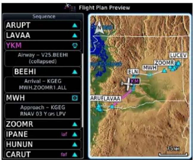
View the flight plan route as it will appear on Map and on the Active Flight Plan app.
Options include Store, Activate

EDIT
Modify the selected flight plan on the Edit Catalog Flight Plan page.
COPY
Create a copy of the selected flight plan. A copy may be used as a starting point for creating a similar flight plan. Select the copy and tap Edit to make modifications.
DELETE A FLIGHT PLAN
Deleting the active flight plan does not delete the stored flight plan in the catalog.
From the FPL menu:
- Tap Menu > Delete.
- Confirm the request.
From the catalog:
- Select a flight plan.
- Tap Delete.
- Confirm the request to delete all waypoints.
DELETE ALL CATALOGED FLIGHT PLANS
To remove all flight plans from the catalog:
- Open the catalog.
- Tap Menu > Delete All.
- Confirm the request to clear the catalog.
- Tap Delete Pending.
- Confirm the request to remove all flight plans pending preview.
Flight Plan Waypoint Options
Options Menu
Activate Leg
Insert Before
Insert After
Along Track
Hold at Waypoint
View Charts
Load Procedure
Load SAR
Waypoint Info
Load Airway
Remove
Selecting a waypoint identifier opens a menu. Changes to the active flight plan take effect immediately.
- Change the active leg
- Insert a new waypoint into a flight plan
- Add a temporary route fix (ATK)
- Add a holding pattern to an existing waypoint
- Add an airway or procedure
- Add a search and rescue pattern
• View waypoint information and related charts - Remove a selected waypoint
Activate Leg Designate any TO waypoint as the active flight plan leg. Requires an active catalog flight plan.
| Insert Before Insert a new waypoint before the selected waypoint. | |
| Insert After Insert a new waypoint after the selected waypoint. | |
| Along Track | Specify an along track offset value before or after the selected waypoint. |
| Hold at Waypoint | Create a user-defined hold at the selected waypoint. Specify hold parameters and preview holding patterns from a dedicated menu page. |
| View Charts Open the Charts page for the selected airport or procedure. | |
| Load Procedure | Open the Procedures app to specify a departure, arrival, or approach for loading. Available controls are dependent upon the relative position of the aircraft to the active flight plan. Options may include: • Activate Approach• Vectors to Final • Activate Missed Approach |
| Load Airway | Assign an airway and exit waypoint to the selected entry waypoint (e.g., intersection, VOR). |
| Load SAR | Open the Search and Rescue function to create and add an SAR pattern after the selected waypoint. |
| Waypoint Info Open the dedicated information page for the selected waypoint. | |
| Remove | Remove the selected waypoint or hold from the active flight plan. |
You may also set a direct course to any existing waypoint in the active flight plan. Select an identifier and tap the Direct To key. Details about Direct To features are provided in the respective section.
Import a Flight Plan

NOTE
Flight plan format on GTN differs from that used by GNS 400W/500W Series navigators.
FEATURE LIMITATIONS
Flight plans over 99 waypoints in length are truncated. As a result, the last waypoint in the imported flight plan may not be the destination airport.
Import Options
You can import flight plans wirelessly from Garmin Pilot or from an SD card. Once imported, they may be previewed and then stored in the catalog or activated.
IMPORT USING CONNEXT
On your portable device: Select the option to transfer the flight plan(s) to GTN.
On GTN: The MSG key flashes, alerting you that a new message is active.
- Tap MSG and read the "Flight Plan Import" message.
-
Tap New FPL to preview the flight plan.
-
For a single flight plan, the preview page opens.
- For multiple flight plans, the catalog opens.
Selecting a cataloged flight plan that is "Pending Preview" opens a slide-out menu.
To view the flight plan, tap Preview. To delete it without viewing, tap Delete.
IMPORT FROM A DATACARD
On your personal computer: Create the flight plan(s) using compatible flight planning software. Save the file(s) to an SD card.
On GTN: After installing the datacard and applying power to the unit, go to the Active Flight Plan page and open the catalog.
From the Flight Plan Catalog:
- Tap Menu > Import.
- Select a flight plan from the list of datacard files.
- Tap Store or Activate.
Potential Import Errors
Pop-up messages alert you when an import problem occurs.
Tapping Next advances through multiple error messages. Tapping OK acknowledges the error and closes the popup.
The following errors can prevent GTN from successfully importing your flight plans.
Full catalog.
Delete any unnecessary catalog entries and try again.
Flight plan contains errors.
Any airways, procedures, or non-user waypoints not found in the database will result in an error. GTN replaces these with locked (lockd) waypoints, which must be resolved prior to activation.
Flight plan exceeds the waypoint limit.
GTN truncates the flight plan to the correct length; however, you should be aware that waypoints are missing from the end of the flight plan, including the destination waypoint.
Along Track Offsets
An along track (ATK) represents a temporary lateral position (or checkpoint) relative to an existing waypoint in the fight plan. Offset distance values range between 1 nm and 200 nm, and may be specified in 1 nm increments.
Unlike database waypoints, ATKs indicate a temporary route fix in the flight plan.
Once created, their position remains fixed until deleted by the pilot. Subsequent changes to the flight plan do not update the ATK's position.
Flight plan allows multiple entries.
ATKs appear in flight plan route depictions on Active Flight Plan and Map.
Inserting an ATK before the selected waypoint results in a negative offset value. Inserting it after results in a positive value.

CREATE AN ATK
From the active flight plan:
- Select a reference waypoint.
- Tap Along Track and specify an offset distance.
- Choose Before or After.
- Tap Enter.
CREATE AN ATK FOR AN ALTITUDE CONSTRAINT
From the active flight plan:
- Select an altitude constraint.
- Tap Along Track and specify an offset distance.
- Choose Before or After.
- Tap Enter > Save.
MODIFY AN ATK OFFSET
Once set, offset distances are not editable.
To adjust an existing offset value:
- Select the ATK from the flight plan.
- Tap Delete.
- Create a new ATK with the correct offset distance.
User Holds

User holds suspend automatic waypoint sequencing until they expire or are removed.
Tapping Hold at Waypoint displays available hold options.
Hold at Waypoint Options

The controls on this page allow you to:
- Specify course, direction, and turn.
- Set leg length according to distance or time.
- Set up an Expect Further Clearance reminder.
- Preview how the defined holding pattern will appear on Map.
- Load the specified hold for activation.
| Course | Specify the course angle. |
| Direction | Select between Inbound or Outbound. |
| Turn | Select between Left Turn or Right Turn. |
| Leg Type | Select Time or Distance. |
| Leg Time | Specify the leg time in minutes and seconds (MM:SS). |
| Leg Distance | Specify the leg distance. |
| Expect Further Clearance (EFC) | Specify a time for the Expect Further Clearance reminder. |
| Load Hold | Accept the specified hold parameters and return to the previous window. |
| Preview | View the defined holding pattern as it will appear on Map. Available on GTN 650Xi Series units only. |
HOLD PREVIEW

A window displays the defined holding pattern on a 2D map of the surrounding area (includes SafeTaxi depictions).
GTN 650Xi SERIES
Tapping Preview displays the hold on a dedicated map page. You may view and load the hold, or return to the setup menu for more options.

CREATE & ACTIVATE A HOLD
From the active flight plan:
- Select a waypoint.
- Tap Hold at Waypoint.
- Specify hold parameters.
- Tap Load Hold.
- Select the hold from the active flight plan.
- Tap Hold Activate.
- Confirm the request.
Search and Rescue Patterns

Create a search and rescue pattern for any off-route course.
Tapping Load SAR displays options for defining a search and rescue pattern for the selected waypoint.
SAR Pattern Options
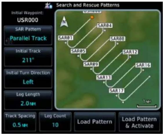
The controls on this page allow you to:
- Select a pattern type.
- Specify an initial track angle and spacing distance.
- Select the turn direction.
• Specify the number of legs. - Load the specified pattern after the selected waypoint.
- Load and immediately activate the specified pattern.
| SAR Pattern | Select a pattern from the list of available types. |
| Initial Track | Specify an initial track angle. |
| Initial Turn Direction | Select between Left or Right. |
| Leg Length | Specify the leg length. |
| Track Spacing | Specify the track spacing distance. |
| Leg Count | Specify the number of legs. |
| Load Pattern | Accept the specified pattern and return to the previous window. |
| Load Pattern & Activate | Accept and activate the specified pattern. |
| Preview | View the defined SAR pattern as it will appear on Map. Available on GTN 650Xi Series units only. |
SAR PATTERN PREVIEW

A window displays the defined pattern on a 2D map of the surrounding area (includes SafeTaxi depictions).
GTN 650Xi SERIES
Tapping Preview displays the pattern on a dedicated map page. You may view and load the pattern, or return to the setup menu for more options.

SAR PATTERN TYPES
Depending on configuration, not all pattern types may be available.

Parallel Track Sector S

Expanding Square

Orbit
CREATE & ACTIVATE A SEARCH AND RESCUE PATTERN
From the active flight plan:
- Select a waypoint.
- Tap SAR Pattern and select a pattern type.
- Review the displayed pattern information. Edit as necessary.
- Tap Load Pattern & Activate.
SAR patterns automatically display as flight plan legs. A search pattern may contain numerous legs.
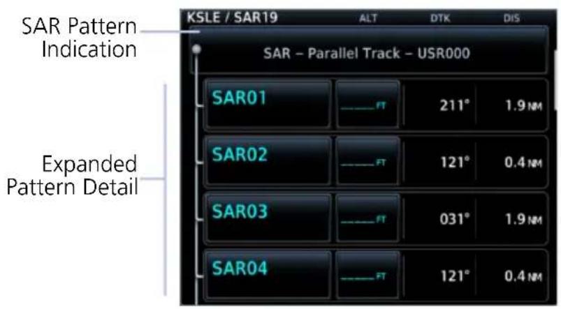
SAR patterns begin with an indicator field and end with an exit identifier.
To activate a pattern leg, select the leg and then tap Activate Leg.
SAR Flight Plan Options

flowchart
graph TD
    A["Search & Rescue Options"] --> B["Collapse Search Pattern"]
    A --> C["Insert Before"]
    A --> D["Select Pattern"]
    A --> E["Remove Pattern"]
Selecting a search pattern indicator from the active flight plan opens a menu. You may elect to:
• Collapse all pattern legs
- Insert a waypoint before the search pattern
- Select a new pattern or modify the existing one
- Remove the search pattern from the active flight plan
Tapping Collapse Search Pattern hides all legs of the pattern except the exit leg.
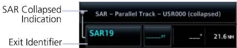
REMOVE A SEARCH AND RESCUE PATTERN
From the active flight plan:
- Select the SAR pattern identifier.
- Tap Remove Pattern.
- Confirm the request.
Flight Plan Map Overlays
Leg Status Indications
| LEG STATUS COLOR | |
| Active Magenta | |
| Next & Future White | |
| Past or Inactive Gray | |
Active, next, and previous flight plan legs overlay on Map and are display only.
Status leg indications.
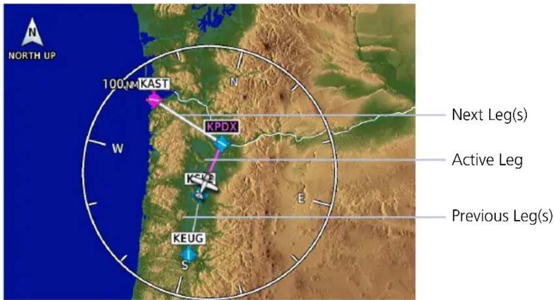
Along Track Offset Indications

Map indications include a dedicated icon and an identifier label. Identifier labels on Map denote the adjacent waypoint's ID and offset distance from the specified ATK.
Selecting an ATK displays its bearing and distance in the info banner.

Unlike waypoints, ATKs indicate a temporary route fix in the flight plan.

Altitude Constraint Labels
Altitude constraint data display as text labels on the Map. Units are typically feet or meters depending on current altitude setting in the System Units app. They display as flight level altitudes if specified as such on the navigator.

If excessive labels are cluttering the map, this feature may be turned off.
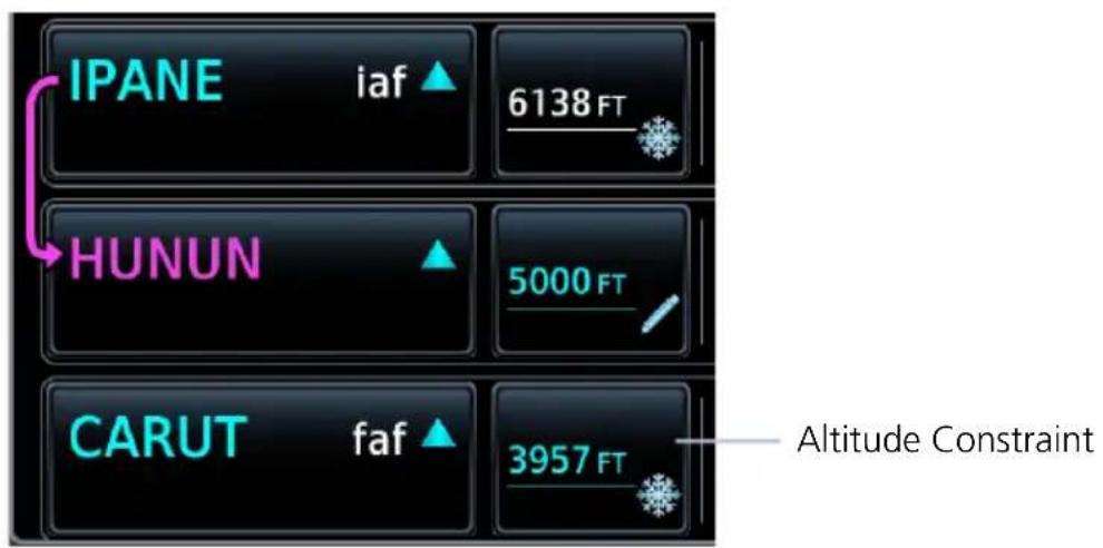
User Airport Icon

A dedicated icon indicates user created airport waypoints. User airport indications display on Active Flight Plan and Map.
When selected, the user identifier annunciates in the info banner.
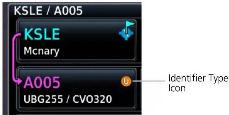

User Identifier
CDI

The CDI function selects data sent from the GPS or VLOC receiver to the external CDI (or HSI).
Tapping the CDI key toggles between navigation sources. If configured, this key resides in the control bar.

NOTE
Information provided by the onscreen CDI is based on GPS data. Do not use for primary navigation.
FEATURE LIMITATIONS
• GPS phase of flight annunciations (e.g., LPV, ENR) are not applicable to the external CDI/HSI when VLOC is active.
• Availability dependent upon configuration
For approaches not approved for GPS, select the VLOC receiver for display on the external CDI/HSI. The selected source annunciates at the bottom of the display.
GPS Receiver VLOC Receiver
GPS
VLOC
If the unit is not configured for a CDI key:
Tapping Activate GPS Missed Approach only resumes automatic waypoint sequencing. To switch to GPS navigation, use your external source selection method (this is typical of an EFIS system).
GTN 650Xi SERIES

CDI scales display on the Default Navigation page (Home > Default NAV).
GTN 750Xi SERIES
CDI scales appear at the bottom of the map display. This indicator is not visible during pan mode.
GPS Nav Status Bar
FEATURE REQUIREMENTS
• Active flight plan for from-to-next route information
This selectable indicator bar shows from-to-next route information when an active flight plan exists. Indications change based on active leg status.
Tapping this bar provides direct access to the active flight plan.

flowchart
graph LR
    A[" "] --> B[" "]
    B --> C[" "]
No Flight Plan Exists
Underscores denote the absence of an active leg.

Active Route Display
Fields change to show active route identifiers and leg types. Includes:
• From, to, and next waypoints
• Leg and waypoint types
- Identifier
GTN 650Xi SERIES

This indicator is a feature of the Default Navigation page (Home > Default NAV).
GTN 750Xi SERIES

GPS Nav status indications appear at the bottom of the map display as part of the CDI. This bar is not visible during pan mode.

flowchart
graph LR
    A["KSLE"] --> B["KPDX"]
    B --> C["KAST"]
Direct To

Set a course to any waypoint using Direct To.
FEATURE LIMITATIONS
• Not all flight plan entries are selectable using Direct To (e.g., holds, course reversals)
• Available search and rescue patterns are dependent upon configuration.
Direct To Basics
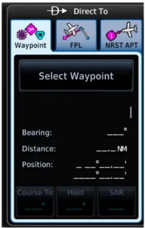
Pushing this bezel key opens a slide-out window. Search tabs provide three different methods of waypoint selection.
- Waypoint: Enter a specific waypoint or find one using additional search tabs.
- FPL: Select a waypoint from the active flight plan.
• NRST APT: Select a nearby airport.
Underscores denote the absence of a loaded course, hold, or search and rescue pattern.
Direct To is useful for quickly navigating to:
- New waypoints
- An existing waypoint in the active flight plan
- Nearby airports
- Map waypoints
• An off-route course
• User-defined holds
When navigating to a single waypoint (e.g., a nearby airport), the Direct To function provides a quicker alternative to using the active flight plan.
Direct To Search Tabs
WAYPOINT

Similar to an information page, but with course and hold options. This tab is active by default.
Selecting an identifier automatically displays the following information about the waypoint.
• Identifier and type icon
- Applicable city, state, country and/or region (e.g., "NW USA")
- Distance and bearing from current aircraft position
- Waypoint coordinates
| Select Waypoint/Identifier Key | Type an identifier or access multiple search tabs using the Find function. |
| Course To | Specify the course angle for the navigation path. |
| Hold | Create, load, and activate a user-defined hold. |
| SAR | Specify a search and rescue pattern. |
FPL & NRST APT
FPL and NRST APT tabs provide a list of selectable identifiers. These tabs have a uniform layout.

Lists all waypoints contained in the active flight plan.
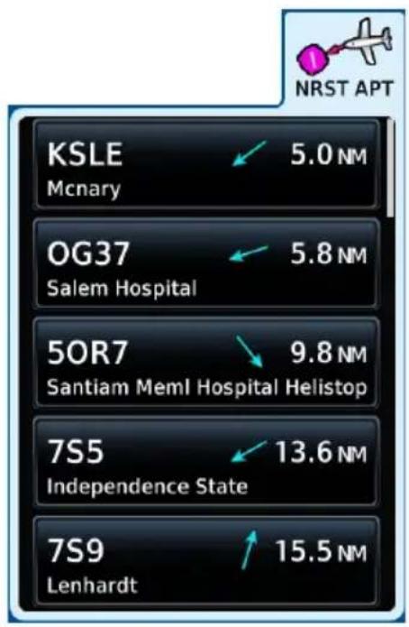
Lists up to 25 waypoints within a 200 nm radius. The closest airport appears at the top of the list.
Direct To Activation
Activating a direct course establishes a point-to-point line from the aircraft's present position to the selected destination.
The unit provides course guidance until you remove the direct-to waypoint, or replace it with a new direct course or flight plan.

natural_image
Close-up of a black mechanical knob or knob component (no text or symbols visible)For convenience, you may activate a direct course using the inner control knob.
After selecting a waypoint, push the knob to activate the direct course.
The window closes and Map opens to show the active leg.
ACTIVE FIX INDICATIONS

Upon activation, Map automatically opens to show a graphical representation of the active direct-to leg.


GPS Nav Status Bar
GPS navigation status changes to show the active direct-to fix. Indication includes the corresponding fix symbol and waypoint identifier.

Map User Field
If configured, a user field shows the active waypoint identifier on Map.

Active Flight Plan Indication
Fix symbol and identifier display in the upper-left corner of the flight plan.
Navigating Direct To
While most direct-to operations follow the same basic steps, the method for selecting a waypoint may vary.
DIRECT TO A NEW WAYPOINT
- Push Direct To.
- Select a waypoint identifier.
- Tap Course and specify the course heading (if a specific course is necessary).
- Activate the selection.
DIRECT TO A FLIGHT PLAN WAYPOINT
Flight Plan Waypoints
If a flight plan exists, waypoint sequencing resumes once you reach the direct-to waypoint. If the waypoint is not in the flight plan, the flight plan is no longer active but remains available.
Direct To options are not available for all flight plan entries. Some entries include holds and course reversals which are not selectable using Direct To.
- Push Direct To.
- Select FPL tab.
- Select a flight p lan leg.
- Activate the selection.
DIRECT TO THE NEAREST AIRPORT
- Push Direct To.
- Select NRST APT tab.
- Select an airport.
- Activate the selection.
DIRECT TO A MAP WAYPOINT
MAPWPT
For map locations without an existing name, Direct To assigns the "MAPWPT" identifier. Bearing, distance, and map coordinates display on the Waypoint tab.
Apply a direct course to any location on the map.
- Select a location on Map.
- Push Direct To.
- Activate the selection.
You can modify direct-to routes on Map using the Graphical Edit function the same as you would a flight plan.
DIRECT TO AN OFF-ROUTE COURSE
You may activate an off-route course using any of the described direct-to methods.
Activating an off-route direct course automatically deactivates the current leg of the active flight plan.
Direct To & Procedure Fixes
Approach guidance is not available for procedure fixes. An example would be activating a direct course to a waypoint between the final approach fix and missed approach point. Upon arriving at the waypoint, approach guidance does not become active.
Remove a Direct Course

To cancel the current direct course, tap Remove.
Removing a direct course:
• Reactivates the original active flight plan
- Assigns the leg nearest to the aircraft's position as the active leg
- Resumes waypoint sequencing
If no active flight plan exists, the aircraft continues on its current heading without any navigation guidance.
User Holds
Define a holding pattern for any direct-to waypoint.

Tapping Hold displays available hold options.
Loading the specified hold parameters returns you to the Direct To window. The Hold key label changes to reflect the specified course angle.
CREATE & ACTIVATE A HOLD

From the Waypoint tab:
- Tap Hold.
- Specify hold parameters.
- Tap Load Hold.
- Activate the selection: Tap Hold Activate or push the inner control knob.
Search and Rescue Patterns
Create a search and rescue pattern for any direct-to waypoint.

Tapping SAR displays options for defining a search and rescue pattern for the direct-to waypoint.

Loading a pattern returns you to the Direct To window. The SAR key label changes to reflect the selected pattern type.
When you create a search and rescue pattern as part of an off-route direct course, the function inserts the associated waypoints at the end of the en route portion of the active flight plan.
CREATE & ACTIVATE A SEARCH AND RESCUE PATTERN

From the Waypoint tab:
- Tap SAR > SAR Pattern, and select a pattern type.
- Review the displayed pattern information.
- Tap Load Pattern.
- Activate the selection: Tap SAR Activate or push the inner control knob.
Procedures
Lateral and vertical guidance is available for visual and GPS/RNAV approaches. The published instrument approach procedures allow precision and non-precision approaches to airports. These are directly accessible via the Procedures app.
FEATURE REQUIREMENTS
- Baro-corrected altitude source (automatic sequencing of altitude leg types)
In the absence of baro-corrected altitude data, altitude leg types require manual sequencing.
FEATURE LIMITATIONS
- Flight Plan allows only one of each procedure type to be loaded at a time; adding a new procedure overwrites any existing procedure of the same type
LOAD A PROCEDURE
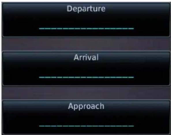
flowchart
graph TD
    A["Departure"] --> B["Arrival"]
    B --> C["Approach"]
Select a procedure type, then define the criteria for that procedure on the corresponding setup page.
By default, these keys display underscores.

Upon completion, the specified airport and procedure appear on the associated key.
When loading a procedure, always remember to check the runway, transition, and all waypoints.
COMMON PAGE CONTROLS
All procedure pages provide the following setup controls.
Airport: Select an airport for the procedure.
Transition: Select a transition.
Runway: Select a runway for the selected airport.
Preview: View a 2D map of the surrounding area (includes SafeTaxi airport depictions).
For page specific controls, refer to the appropriate procedure description.
Flight Procedure Basics

WARNING
Do not rely solely on VNAV guidance when navigating horizontally and vertically around user-defined airports. It is the pilot's responsibility to ensure separation from terrain and obstacles during an approach to a user-defined airport.

NOTE
Advisory climb altitudes for SIDs may not match charted altitudes. Do not rely solely on advisory altitudes.
• Always check the runway, transition, and waypoints for all procedures.
- Heading legs indicate in white as "HDG XXX ^o " on flight plans.
- The unit provides lateral and, when appropriate, vertical guidance for visual and GPS/RNAV approaches.
- Use Map as an aid to situational awareness during ILS, VOR, NDB, and non-precision localizer-based approaches. A magenta line depicts the active leg (or the portion of the approach currently in use).
- Always use the appropriate radio navigational aid for primary approach course guidance during non-GPS approaches.
- Check the annunciator bar for the current phase of flight.
- Many non-precision approaches have GPS overlays, improving accuracy so that approaches do not require overflying a VOR or NDB.
- The unit guides you through complex overlay approaches, automatically sequencing each leg up to the missed approach point.
- Fly approaches as published with the full transition using any published feeder route or initial approach fix, or with a vectors-to-final transition.
- While not required under TSO-C146e, an optional baro-corrected altitude source is recommended for automatic sequencing of altitude leg types.
When adding procedures to a flight plan:
Always verify the transition waypoints between each phase are correct. If using VNAV Descent, verify that the altitudes for the selected procedure match the charted or ATC cleared altitudes and are appropriate for the airframe type.
Map complements your printed approach plates by improving situational awareness during the approach. It does not replace printed approach plates.
Always fly an approach as it appears on the approach plate.
Roll Steering
When switching the CDI source from GPS to VLOC during ILS, VOR, NDB, and non-precision localizer-based approaches, roll steering terminates when approach mode is selected on the autopilot. It becomes available once you initiate the missed approach.
TO/FROM LEGS ON CDI
TO Legs FROM Legs
On these legs, the FROM/TO flag on the CDI indicates "TO" and the Distance field on the flight plan decreases as you navigate the leg.
Most legs are this type
On these legs, the FROM/TO flag on the CDI indicates "FROM" and the Distance field on the flight plan increases as you navigate the leg.
From legs are typically found on procedure turns and on some missed approach procedures.
Localizer or VOR-based Approaches
GTN automatically switches the external CDI output from GPS to VLOC as you intercept the final approach course. When the ILS approach activates and the correct ILS frequency activates in the VLOC window, the GTN automatically switches to VLOC within 1.2 nm left or right of the final approach course. This switch can take place anywhere from 2.0 to 15.0 nm from the FAF.
This illustration shows multiple locations along the approach path and the CDI selection that you can expect: GPS or VLOC. The shaded area depicts where the automatic switch from GPS to VLOC should occur.
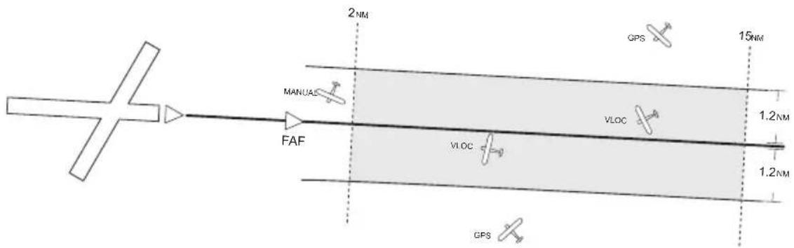
The automatic switch from GPS to VLOC is not immediate, but instead occurs gradually to prevent abrupt CDI changes when coupled to an autopilot. The CDI selection can also be changed manually by tapping CDI.
If you attempt to intercept the approach course at a distance less than 2.0 nm from the FAF, tap CDI to manually switch from GPS to VLOC.
GPS Flight Phase Annunciations
Flight Phase (Caution)

Check the annunciator bar for current phase of flight.
Map complements your printed approach plates by improving situational awareness during the approach. It does not replace printed approach plates.
Always fly an approach as it appears on the approach plate.
Phase of flight annunciations are a direct indication of the current CDI behavior for the selected navigation source. Under normal conditions, these annunciations are green. They turn yellow when cautionary conditions exist.
A caution alerts you when the GPS/WAAS accuracy required for the displayed service level has not been met within the last 30 seconds. This means that an approach downgrade or failure may occur. Always monitor flight phase annunciations and system messages for any change in status.
Not all annunciations are available for every navigator.
| ANNUNCIATION FLIGHT PHASE | |
| 0.30 NM | 0.3 nm CDI scaleBased on pilot selection |
| 1.00 NM | 1.0 nm CDI scaleBased on pilot selection |
| DPRT | DepartureTerminal level with departure procedure as the active navigationSystem using non-precision approach integrityCDI full-scale deflection: 0.30 nm |
| DR | Dead reckoningCDI not available |
| ENR | En routeCDI full-scale deflection: 2.0 nm or current CDI scale selection, whichever is smaller |
| LNAV | Lateral Navigation ApproachFly to published LNAV minimums |
| LNAV+V | Lateral Navigation Approach with Advisory Vertical GuidanceFly to published LNAV minimums |
| LVNAV | Lateral and Vertical Navigation ApproachFly to published LNAV/VNAV minimums |
| LOW ALT | Low AltitudeAircraft's estimated height is lower than the final approach waypoint height by approximately 50 metersFor LNAV+V, LNAV/VNAV, LP +V, or LPV approachesNot active when terrain alerting functions are operational |
| LP | Localizer Performance ApproachFly to published LP minimums |
| LP +V | Localizer Performance Approach with Advisory Vertical GuidanceFly to published LP minimums |
| LPV | Localizer Performance with Vertical Guidance ApproachFly to LPV minimums |
| MAPR | Missed ApproachSystem using missed approach integrityCDI full-scale deflection: ±0.30 nm |
| OCN | OceanicCDI full-scale deflection: 2.0 nm |
| TERM | TerminalCDI full-scale deflection: 2.0 nm or current CDI scale selection, whichever is smaller |
| VISUAL | Visual ApproachVertical guidance based on advisory terrain avoidance calculationsCDI scaling is identical to LPV approaches |
Departures
Loading a Departure into Flight Plan
• Flight plans allow only one departure procedure at a time
- Loading a departure when one is already present will replace the existing entry
- Selecting a departure, transition waypoint, and runway defines the route
FEATURE LIMITATIONS
• Vector-only departures may be excluded from some databases
PAGE SPECIFIC CONTROLS
Load Departure: Loads departure procedure into the active flight plan.
SELECT A DEPARTURE
From the Home page:
- Tap PROC > Departure.
- Confirm the selected airport. If necessary, tap Airport and choose an airport using the provided search options.
- Tap Departure and select a departure from the list.
- Tap Transition and select a transition.
- Tap Runway and select a runway.
- Tap Preview, then review the departure diagram and sequence list.
- Tap Load Departure, then scroll the flight plan to view all departure waypoints.
To change the departure:
Tap the existing flight plan departure and select a different one.
If the selected runway displays a "B," such as "RW10B," this means the selected runway is both 10L and 10R.
Flight Plan Departure Options
Departure Options
View Charts
Select Departure
Remove Departure
Selecting a departure on the flight plan opens a menu. Changes to the active flight plan take effect immediately.
• View chart for selected departure
- Select a new departure
- Remove the selected departure from the flight plan
Arrivals
Loading an Arrival into Flight Plan
- Load a Standard Terminal Arrival (STAR) at any airport with a published arrival procedure
• Flight plans allow only one arrival procedure at a time - Loading an arrival when one is already present will replace the existing entry
- Selecting an arrival, transition waypoint, and runway defines the route
PAGE SPECIFIC CONTROLS
Load Arrival: Loads arrival procedure into the active flight plan.
SELECT AN ARRIVAL
From the Home page:
- Tap PROC > Arrival.
- Tap Arrival > Select an arrival from the list.
- Tap Transition > Select a transition.
- Tap Runway > Select a runway.
- Tap Preview > Review the arrival diagram and sequence list.
- Tap Load Arrival. The Active FPL page opens.
-
Scroll the flight plan to view all arrival waypoints.
-
Confirm the selected airport. If necessary, tap Airport and choose an airport using the provided search options.
To change the arrival:
Tap the existing flight plan arrival and select a different one.
Flight Plan Arrival Options
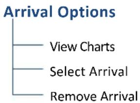
flowchart
graph TD
    A["Arrival Options"] --> B["View Charts"]
    A --> C["Select Arrival"]
    A --> D["Remove Arrival"]
Selecting an arrival on the flight plan opens a menu. Changes to the active flight plan take effect immediately.
• View chart for selected arrival
- Select a new arrival
- Remove the selected arrival from the flight plan
Approaches
Loading an Approach into Flight Plan
• Always check the runway, transition, and all waypoints
• Flight plans allow only one approach procedure at a time
- You may load an alternate approach during a missed approach procedure (flight plan retains all missed approaches)
- Loading an approach when one is already present will replace the existing entry
- Loading and not activating an approach does not remove the approach airport from the flight plan
- Selecting an approach, transition waypoint, and runway defines the route
PAGE SPECIFIC CONTROLS
Load Approach: Loads approach procedure into the active flight plan.
Load Approach & Activate: Loads approach procedure into the active flight plan and activates the approach.
Channel/ID: Loads an SBAS approach based on the specified channel.
SELECT AN APPROACH
From the Home page:
- Tap PROC > Approach.
- Confirm the selected airport. If necessary, tap Airport and choose an airport using the provided search options.
- Tap Approach and select an approach from the list.
- Tap Transition and select a transition.
- Tap Load Approach. The Active FPL page opens.
- Scroll the flight plan to view all approach waypoints.
To change the approach:
Tap the existing flight plan approach and select a different one.
SBAS APPROACHES
Channel ID Key
- Select the channel ID for an SBAS approach to the current destination
- Provides an alternate means of loading an approach.
• IDs are available from an approved approach chart - In the case of duplicate numbers, select an approach from the provided list
To load an SBAS approach:
- Tap Channel/ID.
- Specify an approach channel.
If present, both channel and ID load automatically.
SUSPENDED APPROACH PROCEDURE ANNUNCIATION
"SUSP" indicates that automatic sequencing of approach waypoints is suspended on the active leg. This annunciation appears in the procedure field of the annunciator bar.
Suspended approaches typically occur during:
- Holding patterns
• Crossing the missed approach point - Climb to altitude legs
- Hold to altitude legs
PROCEDURE TURNS
Roll Steering & Procedure Turns
The steering provided for a procedure turn does not guarantee that the aircraft will stay within the charted procedure turn boundaries. Always be sure to fly within the confines of the charted procedure.
A procedure turn is stored as another approach leg. It does not require any special operations other than flying the procedure itself.
Roll steering is available for aircraft with a compatible autopilot.
Flight Plan Approach Options
Approach Options
Activate Approach
Activate Vectors to Final
View Charts
Activate Missed Approach
Select Approach
Remove Approach
Selecting an approach on the flight plan opens a menu. Changes to the active flight plan take effect immediately.
• Activate the selected approach
- Activate vectors to final for the selected approach
• View chart for selected approach
• Activate a missed approach
- Select a new approach
- Remove the selected approach from the flight plan
Missed Approach
The method for activating a missed approach depends on your position in relation to the missed approach point.
BEFORE MISSED APPROACH POINT
Select Activate Missed Approach. This function is available in two applications:
Active FPL:
Home > Flight Plan > Select the approach > Activate Missed Approach
Procedures:
Home > Procedures > Activate Missed Approach
Once selected, guidance continues along an extension of the final approach course (i.e., final approach fix to missed approach point).
The unit automatically sequences to the first leg of the missed approach. This allows you to execute the missed approach prior to reaching the missed approach point.
CROSSING MISSED APPROACH POINT
When crossing the missed approach point:
- "SUSP" annunciation indicates that approach waypoint sequencing is suspended at the missed approach point
- FROM/TO flag on the CDI indicates "From" for non-composite CDIs
- FROM/TO field on the annunciator bar indicates "FR"
• Course guidance continues along the final approach course
If you need to go around the holding pattern again to lose extra altitude or speed, tap SUSP to manually suspend waypoint sequencing before crossing the holding waypoint the second time.
If you have already passed the waypoint, re-activate the holding pattern.
AFTER MISSED APPROACH POINT
Upon reaching the missed approach point, a pop-up presents two options.

To continue with sequencing suspended, tap
Remain Suspended.
To receive guidance to the missed approach hold point, tap
Activate GPS Missed Approach.
Approach Hold
Published holds display on the flight plan one of two ways: with an exit leg or without. Most published holds have three distinct legs.
Hold Entry Leg Hold Leg Hold Exit Leg
This leg is active prior to crossing the hold fix for the first time.
This leg is active after crossing the hold fix for the first time. It remains active until:
- Navigation is unsuspended and the hold fix is crossed again
• The Hold exit leg is activated
This leg is active when the navigator is in an unsuspended state and the aircraft is established inbound.
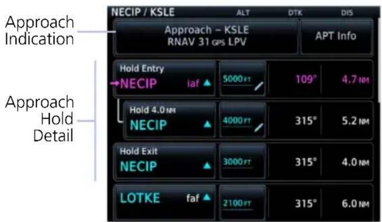
If VNAV is enabled, each hold leg is accompanied by a separate altitude constraint value.
It is the pilot's responsibility to verify that altitude constraints match published charts and ATC clearance.
In this example, the pilot may have received the instruction, "Cross NECIP at 5,000 ft, hold at NECIP, maintain 4,000 ft..."
To stay in the holding pattern, tap SUSP, and the Hold leg will remain active. When you are ready to exit the hold, tap UNSUSP, and the navigation will sequence the next time the airplane crosses the hold fix.
APPROACH HOLDS WITHOUT AN EXIT LEG

Not all published holds support a Hold Exit leg. Some show only Hold Entry and Hold legs. In this case, the Hold leg will remain active until crossing the hold fix for the final time.
It is the pilot's responsibility to fly the procedure in accordance with published charts and ATC clearance.
FLIGHT PLAN APPROACH HOLD OPTIONS
Hold Options

flowchart
graph TD
    A["Activate Hold"] --> B["Insert After"]
    B --> C["Edit Hold"]
    C --> D["Exit Hold"]
    D --> E["Remove"]
Selecting an approach hold on the flight plan opens a menu. Changes to the active flight plan take effect immediately.
• Activate the selected hold
- Insert a waypoint after the hold
- Edit hold details
- Exit the holding pattern
- Remove the selected hold from the flight plan
ACTIVATE HOLD
- Select the hold.
- Tap Activate Hold.
- Confirm the request.
NOTE: Activating the hold will result in direct-to navigation to the hold fix.
REMOVE HOLDING PATTERN

- Select the hold.
- Tap Remove.
- Confirm the request.
EXIT HOLDING PATTERN

- Select the hold.
- Tap Exit Hold.
- Confirm the request.
NON-REQUIRED HOLDING PATTERNS

Upon activating an RNP GPS approach, decide whether to skip non-required holding patterns during the initial transitions of the approach.
A pop-up presents two options.

Selecting Yes adds the hold to the flight plan.
Preview shows the hold in white.

Selecting No means the hold is not included in the flight plan.
Preview shows the hold in gray.
Timer/Distance field displays on the active flight plan (refer to when flying the outbound portion of the holding pattern). Holding pattern appears on Map with the active flight plan leg indication.
DME Arc
DME Arc Approaches
• Left/right guidance relative to the arc
• Manual arc leg activation once aircraft is near the arc
The unit supports approaches containing DME arcs.
To manually activate DME Arc, the aircraft must be within the shaded area.

flowchart
graph TD
    A["Arcing Fix (VOR)"] --> B["Intermediate Approach Fix"]
    B --> C["DME Arc"]
    C --> D["Initial Approach Fix"]
    D --> E["1/2 X"]
    style A fill:#ccc,stroke:#333
    style B fill:#fff,stroke:#333
    style C fill:#ccc,stroke:#333
    style D fill:#fff,stroke:#333
    style E fill:#ccc,stroke:#333
RF Legs
AC 90-101A - RF Legs
AC 90-101A defines RF leg as "A constant radius circular path, around a defined turn center, that starts and terminates at a fix. An RF leg may be published as part of a procedure."
The unit supports radius-to-fix (RF) legs associated with RNAV RNP 1.0 non-AR approaches, when approved by the installation.
Flying a radius-to-fix approach is similar to flying a DME arc approach (status indications are identical).
Unlike DME arcs, however, RF legs are not based on a VOR. They may have varying radii, making them larger or smaller than arc legs.
For details regarding RF legs for specific aircraft, consult the AFMS.
Vectors to Final

Activating the approach with vectors to final displays an extension of the final approach course on Map.

Magenta depicts the active leg of the flight plan. CDI needle remains off center until you are established on the final approach course.
As a reminder, "vtf" annunciates as part of the active leg on the GPS Nav status bar.
Activating vectors-to-final while on the From side of the final approach fix suspends automatic waypoint sequencing. "SUSP" annunciates at the bottom of the screen. Sequencing resumes once the aircraft is on the To side of the final approach fix and within full-scale deflection.
ILS Approach

NOTE
ILS and LOC approaches are not approved for GPS. GPS guidance is for monitoring purposes only.
Selecting an ILS or LOC approach results in a pop-up message. Activate the approach or select a different one.
Do not attempt to use the unit as the primary navigation source during ILS approach.
VOR+V Approaches
Per guidance provided in AC 90-108 regarding the use of GPS as an alternate means of navigation, VOR and NDB approaches may be treated as LNAV+V approaches (i.e., LNAV with advisory vertical guidance) as long as the pilot monitors the VOR.

During approach selection, "+V" displays for VOR and NDB approaches when advisory guidance is available. Approach strings remain unmodified when no vertical guidance is available.
If the approach indicates "VOR+V," then advisory vertical guidance may be removed without indication. This is due to the vertical guidance not being within tolerances.
This does not constitute a downgrade. You may still fly the approach to VOR minimums.
Flying a VOR approach with advisory vertical guidance (VOR+V) does not change how the approach should be flown. The pilot is still responsible for descending to the correct altitude at each step down.
The result is still an MDA and missed approach point.
RNAV Approaches
Always fly to the published minimums for:
Fly RNAV approaches according to the published chart.
LNAV APPROACH
RNAV non-precision lateral navigation approach.
LNAV+V APPROACH
RNAV non-precision LNAV approach with advisory vertical guidance.
The glidepath is a light dashed line on the vertical profile (Jeppesen charts only) with an associated glidepath angle (usually in the 3.00 degree range) to assist in maintaining a constant vertical glidepath, similar to an ILS glideslope.

CDI scale varies when VTF is active.
LPV APPROACH
Localizer performance with vertical guidance. Similar to flying the standard ILS approach.
This segment describes a typical LPV approach sequence and the necessary pilot actions.
Within 31 nm of destination:
• Mode switches from En Route to Terminal
• CDI scale transitions from 2.0 nm to 1.0 nm, full-scale deflection
Approaching initial approach fix:
• Waypoint message annunciates
- Time to Turn advisory annunciates and 10 second timer counts down as the distance approaches zero
Approaching final approach fix:
• Mode switches from Terminal to LPV
2.0 nm from final approach fix:
- CDI scaling tightens from 1 nm to the approach-defined angular full-scale deflection
60 seconds before final approach fix:
• System verifies GPS position integrity is within approach limits
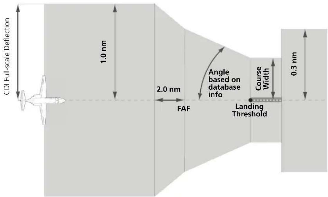
CDI scale varies when VTF is active.
If GPS integrity exceeds the horizontal and/or vertical alarm limits:
- Approach downgrades to non-precision
- "LNAV" annunciates on Map to inform of the change if there are LNAV minimums for the approach
- Advisory message: "GPS approach downgraded. Use LNAV minima."
• Glideslope indication disappears -
Pilot continues approach using LNAV non-precision minimums, if applicable. If GPS integrity does not meet the non-precision horizontal alarm limits:
-
Advisory message: "Abort Approach. GPS approach is no longer available."
- Pilot acknowledges message
- Unit reverts to terminal limits of 1 nm to support navigation to the missed approach
When crossing the final approach fix:
- Waypoint sequences to the missed approach point (e.g., RW31, the runway threshold)
- Pilot flies toward missed approach point, keeping the needle on the external CDI (or HSI) at center, and observing published altitude minimums
• Final course segment becomes the active flight plan leg on Map
After the aircraft passes final approach fix:
- Pilot captures the glidepath (method is same as for ILS glideslope)
Approaching missed approach point:
- Advisory message: "Arriving at Waypoint."
Crossing missed approach point:
- Sequencing suspends
- Pop-up message: "Missed Approach Waypoint Reached"
- Pilot decides whether to remain suspended or activate the missed approach
- Tapping Remain Suspended allows you to continue with sequencing suspended
- Tapping Activate GPS Missed Approach allows you to continue with guidance to the missed approach hold point
Prepare aircraft for missed approach operation:
- Pilot taps UNSUSP (sequences missed approach), then follows the unit provided guidance to the missed approach hold point and holds
LP APPROACH
Points About LP Approaches
• Use SBAS accuracy, making them similar to an LNAV approach but more precise
- Combine the lateral accuracy of an LPV approach with the angular scaling of a localizer approach
- Often contain step-down altitudes
• Always result in a minimum descent altitude and missed approach point
This segment describes a typical LP approach sequence and the necessary pilot actions.
Within 30 nm of destination:
• Mode switches from En Route to Terminal
• CDI scale transitions from 2.0 nm to 1.0 nm, full-scale deflection
Approaching initial approach fix:
• Turn direction message annunciates
- Time to Turn advisory annunciates and 10 second timer counts down as the distance approaches zero
Approaching final approach fix:
- Unit begins to automatically rescale in an angular fashion, allowing you to fly as you would a standard localizer approach
2.0 nm from final approach fix:
- CDI scaling tightens from 2 degrees or 0.3 nm full-scale deflection, whichever is smaller
60 seconds before final approach fix:
- System verifies GPS position integrity is within the horizontal limits to complete the LP non-precision approach
If pilot exceeds the horizontal alarm limits:
- Approach downgrades to non-precision
- "LNAV" annunciates on Map to inform of the change
- Advisory message: "GPS approach downgraded. Use LNAV minima."
- Pilot continues approach using LNAV non-precision minimums, if applicable
If GPS integrity does not meet the non-precision horizontal alarm limits:
- Advisory message: "Abort Approach. GPS approach is no longer available."
- Pilot acknowledges message
- Unit reverts to terminal limits of 1 nm to support navigation to the missed approach
If the approach indicates “LP+V,” then advisory vertical guidance may be removed without indication. This is due to the vertical guidance not being within tolerances.
This does not constitute a downgrade. You may still fly the approach to LP minimums.
Flying an LP approach with advisory vertical guidance (LP+V) does not change how the approach should be flown. The pilot is still responsible for descending to the correct altitude at each step down.
The result is still an MDA and missed approach point.
When crossing the final approach fix:
- Waypoint sequences to the missed approach point (e.g., RW31, the runway threshold)
- Pilot flies toward missed approach point, keeping the needle on the external CDI (or HSI) at center, observing published altitude minimums
• Final course segment becomes the active flight plan leg on Map
Approaching missed approach point:
- Advisory message: "Arriving at Waypoint."
Crossing missed approach point:
- Sequencing suspends
- Pop-up message: "Missed Approach Waypoint Reached"
- Pilot decides whether to remain suspended or activate the missed approach
- Tapping Remain Suspended allows you to continue with sequencing suspended
- Tapping Activate GPS Missed Approach allows you to continue with guidance to the missed approach hold point
Prepare aircraft for missed approach operation:
- Pilot taps UNSUSP (sequences missed approach)
NOTE: For missed approaches with heading legs, fly manually until you reach the first active course leg.
- Pilot follows the unit provided guidance to the missed approach hold point and holds
Visual Approach
Points About Visual Approaches
- Provide advisory horizontal and optional vertical guidance for the selected runway
• Lateral guidance is always provided for visual approaches
• Helps stabilize the runway approach
• Three methods for loading and activation
FEATURE REQUIREMENTS
- Valid terrain database
FEATURE LIMITATIONS
• Not all airports in the database support visual approaches
Published data is used to determine the visual approach GPA and threshold crossing height (TCH) for the selected runway. If no published data is available, the default is 3 degrees GPA and 50 ft TCH.
You may load and activate a visual approach from the following apps.
- Map
- Procedures
- Waypoint Info

Upon loading the visual approach, a pop-up informs when vertical guidance is available.
If available, the pop-up contains the glidepath angle (GPA) and threshold crossing (TCH).
If unavailable, it reads: "NO VERTICAL GUIDANCE"
Terrain and obstacle obstructions along the approach path determine the availability of vertical guidance advisories for visual approaches.
- If no known obstructions are within the approach path, vertical guidance is provided to a maximum distance of 28 nm from the runway.
- If there are known obstructions further than 3 nm, but within the 28 nm maximum distance from the runway along the approach, vertical guidance is limited to the approach path after crossing the known obstructions. After loading the approach, a shortened magenta line shows on the map.
If obstructions are within 3 nm to the runway, along the approach path, advisory vertical guidance is not available.
LOAD A VISUAL APPROACH FROM MAP
When the aircraft is within 10 nm of the destination airport, the Visual Approach selector key becomes active. This key may appear in one of two places:
On the map or at the left of the screen if the supporting airport is selected.
- Select the airport icon.
- Tap Visual.
- Select from the list of available visual approaches.
Once selected, the visual approach immediately loads and activates.
For more about Visual Approach key configuration, refer to Map Setup.
LOAD A VISUAL APPROACH FROM PROCEDURES
Two methods:
Home > PROC > Approach
OR
Home > Waypoint Info > Airport > PROC, then select an approach (similar to published instrument approaches)
Autopilot Outputs

CAUTION
Engage the autopilot heading mode and set the heading bug appropriately to use the autopilot on heading legs using the autopilot's NAV, GPSS, or APR mode. Not all autopilots follow guidance on these leg types, Some revert to a roll only or wings level mode.
FEATURE REQUIREMENTS
• Availability dependent upon configuration
FEATURE LIMITATIONS
• Applicable to King KAP 140 and KFC 225 autopilots

Outputs for the King KAP 10/KFC 225 autopilot units require manual activation.
APR Guidance Advisory, GTN 650Xi

If configured, this function prompts you to enable autopilot outputs during the approach procedure.
Once enabled, the unit provides guidance information consistent with what the autopilot expects (i.e., angular CDI scaling and glideslope capture for LPV or other vertically guided GPS approaches).
ENABLE AUTOPILOT OUTPUTS
- Acknowledge the advisory message.
- Tap Enable APR Output.
- Follow the unit provided guidance.
4 Planning
VCALC 4-4
TRIP PLANNING 4-7
FUEL PLANNING 4-11
DALT/TAS/WIND CALCULATOR 4-15
RAIM PREDICTION....4-18
CHECKLISTS....4-20
PLANNING APPS & FUNCTIONS
The following features make flight planning easier and more efficient.
VCALC
Input:
- Target Altitude
- Altitude Profile
- Target Waypoint
GTN computes:
• Time to TOD
- VS Required

Trip Planning
Input:
- Route
- Depart Date/Time
- Ground Speed
GTN computes:
• DIS
DTK
ESA
• ETA
• ETE
- Sunrise/Sunset

RAIM Prediction
Input:
- Waypoint
- Arrival Date/Time
GTN computes:
- RAIM Status

Checklists
- Review and complete aircraft checklists

Fuel Planning
Input:
- Route
- Fuel Data
- Ground Speed
DALT/TAS/Winds
Input:
- Air Data
- Track
- Heading
- Ground Speed
GTN computes:
- Fuel Required
- Reserve
- Range
- Efficiency
• Endurance
GTN computes:
- Density ALT
• TAS - Wind Direction
- Wind Speed
- Head Wind
VCALC and VNAV are mutually exclusive. Which app you have is dependent upon installer configuration. For information about VNAV functions and operations, read En Route Vertical Navigation in section 3.
VCALC
Calculate time to TOD and vertical speed required to reach target altitude at the specified location.

WARNING
Do not rely on VCALC messages as the only means of either avoiding terrain/obstacles or following ATC guidance. VCALC provides advisory information only and must be used in concert with all other available navigation data sources.
FEATURE LIMITATIONS
This feature is inhibited when:
• Groundspeed is < 35 knots
• No active flight plan or direct-to destination is available
• One of the following modes is active: SUSP, Vectors-to-Final, OBS
• Navigating to a waypoint after the FAF
Define a VCALC Profile
WHERE TO FIND IT

flowchart
graph TD
    A["Home"] --> B["Utilities"]
    B --> C["VCALC"]
With the Vertical Calculator (VCALC) feature, you can create a 3D profile to guide you from your present position and altitude to a final (target) altitude at a specified location. Once defined, you may configure message alerts and additional data on Map to stay informed of your progress.

Creating a profile is helpful when you want to descend to a certain altitude near an airport.

flowchart
graph TD
    A["Target ALT"] --> B["Specify target altitude"]
    C["Altitude Type"] --> D["Above WPT MSL"]
    E["VS Profile"] --> F["Specify vertical speed"]
    G["Offset"] --> H["Specify offset value"]
    I["Target Waypoint"] --> J["Select flight plan waypoint"]
Profile selections allow you to:
- Specify a target altitude and offset
- Choose a target type
- Specify vertical speed
- Select a target waypoint from the active flight plan
Target ALT • Specify the final (target) altitude for the course
| Altitude Type | Altitude reference used for VCALC calculationsToggles between “MSL” and “Above WPT“Above WPT is available for airports only |
| VS Profile | Specify the vertical speed value |
| Offset | Distance value representing the geographical location at the target altitudeDistance is measured from the target waypoint along the flight path |
| Before/After | Select whether the offset distance defines a point before or after reaching the target waypoint“After” option not available for last destination in flight plan (key changes to a non-selectable “Before” indication) |
| Target Waypoint | Reference location specified in the flight plan or active direct-to that will be used for planning a descentWhen using a flight plan, the target waypoint is a reference that can be specified from the waypoints in the flight planLast waypoint in the flight plan is the default target setting |
STATUS & VS REQUIRED INDICATIONS
Status
VS Required
Descend to target
-502 FPM
Status
VCALC status messages display here.
VS Required
Shows the vertical speed required to reach target altitude and offset.
VCALC Setup

Messages
VCALC
Approaching top of descent.
Setup options allow you to restore default app settings and display VCALC related advisory messages.
Restore Defaults Display Messages
Restore Defaults
- Resets VCALC settings to their default values
• Excludes Target Waypoint
Display Messages
- Allows VCALC related advisory messages to display on the Messages page
GTN 650Xi SERIES
VCALC Menu
Restore Defaults
Display Messages
Tap Menu to access setup controls.
GTN 750Xi SERIES
Setup controls reside on the profile page.
Trip Planning

View DTK, DIS, ETE, ESA, and ETA information for a direct course between two specified waypoints or any programmed flight plan.
WHERE TO FIND IT
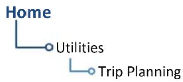
flowchart
graph TD
    A["Home"] --> B["Utilities"]
    B --> C["Trip Planning"]
Trip statistics are based on route and ground speed.
Trip Planning Modes
Tapping Mode toggles the active trip planning mode between Point to Point and Flight Plan. Point to Point is the default mode setting.
Point-to-Point Mode Flight Plan Mode
Calculate trip data between two waypoints in the database, or between the aircraft's present position and a selected waypoint.
Calculate trip data for a specific flight plan leg, or for the cumulative flight plan.
Use the mode specific controls to define the flight path (leg or route). Required input values are dependent upon mode selection.
Departure date and time and ground speed data are required independent of mode selection.
MODE SELECTION DESCRIPTION
| Point-to-Point | P. Position | ·Enters the current aircraft coordinates as the departure location (or From waypoint) ·Aircraft latitude and longitude fields replace the From waypoint key |
| From | ·Specify a waypoint from the database as the departure location (or From waypoint) ·Not available when P. Position is active | |
| To | ·Specify a waypoint from the database as the destination (or To waypoint) | |
| Flight Plan | Flight Plan | ·Opens a list of available flight plans ·Options include the active flight plan or one from the catalog ·Defaults to the active flight plan if no selection is made |
| Leg | ·Options dependent upon flight plan selection ·Defaults to cumulative leg option if no selection is made | |
| Both | Depart Time | ·Specify the departure time (local time at From waypoint) |
| Depart Date· | Specify the year, month, and day of departure | |
| Use Sensor Data | ·Utilize current GPS ground speed data | |
| Ground Speed | Behavior based on state of Use Sensor Data key.Use Sensor Data key inactive: ·Function selectable ·Specify ground speed Use Sensor Data key active: ·Function not selectable ·Displays current GPS ground speed when the Use Sensor Data key is active |
COMPLETED LEG INDICATION

Dashes indicate when the selected flight plan leg is completed or the data cannot be computed.
Trip Statistics
Trip statistics include:
• Desired track (DTK)
- Distance (DIS)
- Destination sunrise/sunset times
• Est. time en route (ETE)
• Est. time of arrival (ETA)
• En route safe altitude (ESA)
Trip data calculations are based on the selected trip planning mode and specified input values.
This information is for planning purposes only.
DESTINATION SUNRISE/SUNSET TIMES
WHERE TO FIND IT

flowchart
graph TD
    A["System"] --> B["Setup"]
    B --> C["Date/Time"]
The time zone on which destination sunrise/sunset calculations are based depends on the system Time Format setting. This option resides in the System – Setup Date/Time feature.
Local 12 or 24 hour. Calculations are based on the time zone of the From waypoint. A flight plan originating in the Pacific time zone and ending in the Central time zone would show sunrise/sunset times at the destination in Pacific time.
UTC. Calculations use Universal Time Coordinated (time zones are not considered). There is no potential offset.
ETA CALCULATIONS
The method for calculating ETA varies based on mode selection.
Point-to-Point mode. ETA = ETE + departure time
Flight Plan mode. Calculations depend on flight plan selection:
| If Then | |
| Active Flight Plan | ETA reflects the present position and active leg:ETA = current time + ETE of each leg from the active leg up to and including the selected leg |
| Catalog Route | ETA = departure time + ETE of each leg up to and including the selected leg |
If you select the entire flight plan, the last leg of the flight plan is treated as the selected leg. This is true whether the selected flight plan is active or inactive.
GTN 650Xi SERIES

To calculate trip data, enter all required input values and then tap Compute Data.

Statistics for the selected leg or route display on a dedicated data page.
To return to the data entry page, tap Edit Input Data.
GTN 750Xi SERIES
Trip data calculates automatically upon entry. Statistics for the selected leg or route display on the lower half of the page.
COMPUTE TRIP STATISTICS
- Select a trip planning mode.
-
Define a leg or route.
-
If "Flight Plan" is set, select the flight plan and leg. Selecting the active flight plan sets the starting waypoint at the aircraft's current position.
-
If "Point to Point" is set, select From and To waypoints, or use the aircraft's current position as the From waypoint.
-
Specify the departure date and time.
- Specify ground speed or elect to use sensor data.
- Tap Compute Data (GTN 650Xi Series only).
- Tap Next or Prev to view statistics for other legs in the flight plan (if applicable).
Fuel Planning

View fuel conditions along any flight plan (active or cataloged) or between two waypoints (including the active direct-to).
WHERE TO FIND IT

flowchart
graph TD
    A["Home"] --> B["Utilities"]
    B --> C["Fuel Planning"]
The fuel planning feature computes fuel conditions based on route, ground speed, fuel on board, and fuel flow.
Input values may be entered manually or supplied by sensors, if connected.
Fuel Planning Modes

Tapping Mode toggles the active fuel planning mode between Point to Point and Flight Plan. Point to Point is the default mode setting.
Point-to-Point Mode Flight Plan Mode
Calculate fuel between two waypoints in the database, or between the aircraft's present position and a selected waypoint.
Calculate fuel for a specific flight plan leg, or for the cumulative flight plan.
Use the mode specific controls to define the flight path (leg or route). Required input values are dependent upon mode selection.
Fuel on board, fuel flow, and ground speed data are required independent of mode selection.
For Planning Purposes Only
- When interfaced with a Garmin EIS, Fuel on Board and Fuel Flow values are supplied by EIS. If an EIS is not present, or if the Use Sensor Data function is not active, these values are specified by the pilot and are not an indication of actual fuel on board or fuel flow.
- Fuel Required to
is a calculated prediction. It is not a direct indication of actual fuel quantity once the aircraft reaches its destination. - All data entries on this page are used exclusively by the Fuel Planning app.
• Fuel computations are for planning purposes only.
MODE SELECTION DESCRIPTION
| Point-to-Point | P. Position | ·Enters the current aircraft coordinates as the departure location (or From waypoint) ·Aircraft latitude and longitude fields replace the From waypoint key |
| From | ·Specify a waypoint from the database as the departure location (or From waypoint) ·Not available when P. Position is active | |
| To | ·Specify a waypoint from the database as the destination (or To waypoint) | |
| Flight Plan | Flight Plan | ·Opens a list of available flight plans ·Options include the active flight plan or one from the catalog ·Defaults to the active flight plan if no selection is made |
| Leg | ·Options dependent upon flight plan selection ·Defaults to cumulative leg option if no selection is made | |
| Both | Fuel on Board | ·Specify the amount of fuel on board (gallons) ·Amount decreases once per second based on specified fuel flow value or sensor data |
| Fuel Flow | ·Specify the current fuel flow rate (gallons per hour) | |
| Use Sensor Data1 | ·Toggle on to utilize current GPS ground speed data and fuel sensor data (if available) ·Toggle off for manual data entry | |
| Ground Speed | ·Specify ground speed |
^1 When inactive, ground speed and fuel data functions are selectable. When active, these functions are not selectable.
Adjust fuel on board and fuel flow values as necessary to account for changes in performance.
Fuel Statistics
Fuels statistics include:
- Fuel required for leg
- Fuel after leg
- Reserve after leg
- Range
- Efficiency
• Endurance
Compute and display fuel data based on the selected fuel planning mode and specified input values.
This information is for planning purposes only.
GTN 650Xi SERIES

To calculate fuel data, enter all required input values and then tap Compute Data.

Statistics for the selected leg or route display on a dedicated data page.
To return to the data entry page, tap Edit Input Data.

GTN 750Xi SERIES
Fuel data calculates automatically upon entry. Statistics for the selected leg or route display on the lower half of the page.
COMPUTE FUEL STATISTICS
- Select a fuel planning mode.
-
Define a leg or route.
-
If "Flight Plan" is set, select the flight plan and leg. Selecting the active flight plan sets the starting waypoint at the aircraft's current position.
-
If "Point to Point" is set, select From and To waypoints, or use the aircraft's current position as the From waypoint.
-
Specify the amount of fuel on board and average fuel flow rate.
- Specify ground speed or elect to use sensor data.
- Tap Compute Data (GTN 650Xi Series only).
- Tap Next or Prev to view statistics for other legs in the flight plan (if applicable).
If total fuel quantity or fuel flow values are supplied via sensor, GTN uses the data from this app to calculate the Fuel Range Ring overlay on Map. Fuel range rings indicate an estimate of remaining flight distance based on fuel onboard, fuel consumptions rates, and current ground speed.
Map depicts two separate rings: one displaying range to reserve fuel, the other displaying total endurance range. Both offer additional situational awareness regarding fuel remaining and endurance.
DALT/TAS/Wind Calculator

Calculate density altitude, true airspeed, and winds.
FEATURE REQUIREMENTS
• Air data computer for automatic data entry
- Valid sensor data
An air data computer is not required for manual data entry.
WHERE TO FIND IT

flowchart
graph TD
    A["Home"] --> B["Utilities"]
    B --> C["DALT/TAS/Winds"]
This function computes density altitude, true airspeed, and wind data to provide the theoretical altitude at which your aircraft performs. Information is based on several input variables, which may be provided manually or via an air data computer.
Edit Input Data
Tapping Use Sensor Data inputs data from the connected sensors. When active, the available sensor data populate the appropriate fields.
Sensor data values are not selectable for editing. Toggle the function off for manual data entry.
| Indicated ALT | Specify indicated altitude valueUse +/- keys to indicate above or below sea levelMutually exclusive with Pressure ALT ^1 |
BARO • Specify barometric pressure value 2
CAS • Specify calibrated air speed value
| TAT | Specify true air temperatureUse +/- keys to indicate above or below 0° |
HDG • Specify heading value
TRK • Specify track angle value
| Use Sensor Data | • Inputs reference values (internal or received from air data computer) • Replaces indicated altitude with pressure altitude received from fuel/air data computer |
Ground Speed • Specify ground speed
^1 Toggles to Pressure ALT indication when sensor data is in use and the sensor is providing pressure altitude.
^2 Not present if Use Sensor Data is active and the ADC is providing pressure altitude.
DALT/TAS/Wind Statistics
Compute and display density altitude and current wind conditions. Calculations are based on current input values.
This information is for planning purposes only.
Density Altitude Wind Data
- Pressure altitude corrected for nonstandard temperature
• Units display in increments of ten
• Wind direction and speed
- Headwind
- True air speed
Density altitude and true airspeed calculations are dependent upon indicated altitude, barometric pressure, and total air temperature. Total air temperature includes temperature and the heating effect of speed, as read on a standard outside temperature gauge.
Wind data calculations are dependent upon aircraft heading and track, true airspeed, and ground speed.
Wind direction is dependent upon the NAV Angle system unit setting.
If wind speed is zero, wind direction displays as dashes.
GTN 650Xi SERIES

To calculate density altitude and wind data, enter all required input values and then tap Compute Data.

Statistics display on a dedicated data page.
To return to the data entry page, tap Edit Input Data.

GTN 750Xi SERIES
Data calculates automatically upon entry. Statistics for the selected leg or route display on the lower half of the page.
INVALID INPUT DATA INDICATION

Dashes indicate when input values are invalid.
RAIM Prediction

Determine GPS coverage availability for the current location or a specified waypoint at any time and date. RAIM performs checks to ensure that the navigator has adequate satellite geometry during flight.

NOTE
RAIM availability prediction is for use in areas where WAAS coverage is not available. It is not required in areas where WAAS coverage is available.
FEATURE REQUIREMENTS
• Active flight plan or off-route direct-to waypoint (arrival date and time)
FEATURE LIMITATIONS
FAA's TSO requirements for non-precision approaches specify significantly greater satellite coverage than is required during other phases of flight. As a result, RAIM may not be available for all approaches.
RAIM prediction results are valid for up to 90 days from the current date. Arrival dates beyond 90 days, or in the past, may not provide accurate results.
This feature predicts the availability of fault detection integrity. It cannot predict the availability of LPV or L/VNAV approaches.
Use a non-GPS based approach when RAIM is not available. To determine WAAS availability, including for LPV approaches, visit the FAA's NOTAM service.
WHERE TO FIND IT

flowchart
graph TD
    A["Home"] --> B["Utilities"]
    B --> C["RAIM Prediction"]
This feature can help you plan for a pending flight by confirming GPS operation before an approach.
RAIM Features
- Automatically monitors RAIM during approach operations and warns when RAIM is not available
- Near 100% availability in Oceanic, En route, and Terminal phases of flight
• Waypoint Identifier, Arrival Date, and Arrival Time setup keys - Compute RAIM key
Calculate RAIM Status

Calculate RAIM availability for the specified waypoint, date, and time. Prediction results annunciate once the calculation is complete.
WAYPOINT SEARCH OPTIONS
A Waypoint Identifier key allows you to specify a destination airport using multiple search options.
ARRIVAL DATE & TIME
These setup controls allow you to set the expected date and time of arrival at the specified airport. Values default to the current date and time in the absence of an active flight plan and off-route direct-to waypoint.
CHECK RAIM AVAILABILITY
- Specify a destination waypoint.
- Specify the expected arrival date and time.
- Tap Compute RAIM.
RAIM STATUS INDICATIONS
Dashes indicate when the destination waypoint is invalid.
| ANNUNCIATION DESCRIPTION | |
| Computing Status is pending. | |
| RAIM Available RAIM is available at the specified waypoint. | |
| RAIM Unavailable RAIM is not available at the specified waypoint. |
Checklists

Review an electronic version of your aircraft checklist(s). Depending on the number of inspection items, these lists may be scrollable.
This icon appears only when GTN detects a checklist on your SD card.

NOTE
Garmin strongly recommends the author of the checklist file to carry out a functional system test prior to in-flight use. Validation should be carried out on the GTN Xi Series hardware while the aircraft is on ground.
FEATURE REQUIREMENTS
• SD card for storing checklist files
• Garmin Aviation Checklist Editor software tool for authoring and grouping
FEATURE LIMITATIONS
- Check boxes automatically clear following a unit power cycle
• Feature title dependent upon installer configuration
WHERE TO FIND IT

flowchart
graph TD
    A["Home"] --> B["Utilities"]
    B --> C["Checklists/Task Lists"]
Depending on configuration, this feature may be titled "Checklists" or "Task Lists."
Disclaimer
Operational approval may be required for the use of any electronic checklist developed for certified aircraft. Any checklist created with the checklist tool for certified aircraft may require additional operational airworthiness approval and cannot replace the official Flight Manual and/or checklist required by the Type Certificate or Supplemental Type Certificate. Do not use an unapproved checklist during flight operations.
User generated checklists are created using the free Aviation Checklist Editor software available at flyGarmin.com.
Define properties for groups, checklists, and new entries using the features provided in the software tool.
Save checklists in the chklist.ace format. Copy the file to the root folder of an SD card.
For download instructions and system requirements, visit the Aviation Product Support page at flyGarmin.com.
View a Checklist

flowchart
graph TD
    A["Checklist Menu"] --> B["Group"]
    B --> C["Select Checklist Group"]
    A --> D["Checklist"]
    D --> E["Select Checklist"]
    A --> F["Clear Current Checklist"]
    A --> G["Clear All Checklists"]
Tap Menu to access available group and checklist selections. Functions for clearing check boxes on the active list and all other checklists on the datacard also reside here.
| Group | Select from the list of existing groups. Group properties are defined during checklist creation. |
| Checklist Select a checklist for viewing and completion. | |
| Clear Current Checklist | Clears all check boxes for the active list. |
| Clear All Checklists | Clears the check boxes for all available checklists on the installed SD card. |
CHECK BOXES
To mark an item as completed, tap the corresponding check box.

Cabin Heat & Defrost ...... On
The item description turns green
A check mark appears next to the list item

Tapping the box again deselects the item.
Deselected
LIST STATUS ANNUNCIATIONS
Completion status annunciates at the bottom of the list.

One or more list items are not marked as complete. Review the list and complete the remaining inspection items.

All check boxes are marked as complete. Proceed to the next checklist or select a different list from the menu.
COMPLETE A CHECKLIST
- Insert SD card containing the file titled chklist.ace.
- Open the Checklist menu (Home > Utilities > Checklists > Menu).
- Select a group.
- Select a checklist.
- Select Clear Current Checklist or Clear All Checklists (if necessary).
- Review and complete all inspection items.
Upon completion, select from the following options.
- Advance to the next available checklist: Tap Go to Next Checklist.
- Exit the function: Tap Back.
- Select another checklist: Tap Menu and select another group and/or checklist.
5 Hazard Awareness
WEATHER AWARENESS....5-3
Menu selections vary based on features and optional equipment installed with Garmin avionics.

Traffic
- Display traffic
• Control traffic system - Set up the traffic display

Terrain
• Display terrain & obstacles
- Inhibit alerting
- Test alerting

Weather
Access available weather apps. Depending on unit configuration these may include:
- SiriusXM WX
- FIS-B WX
- Connext WX
- Stormscope
- Radar
Weather Awareness

For installations with multiple weather sources, tapping the Weather icon on the Home page opens a menu. Available options are dependent upon the installed weather sources.
For installations with only a single weather source, tapping the icon takes you directly to the configured application.
Datalink Weather


GTN presents datalink weather data as overlays on the dedicated weather app. Available functions are dependent upon the active weather source(s).
The unit allows up to three datalink weather options:
- SiriusXM • FIS-B • Connex
FEATURE REQUIREMENTS
• FIS-B and GDL 88 or GTX 345 (FIS-B Weather)
• GSR 56 Iridium satellite transceiver (Connext Weather)
• GDL 69/69A SiriusXM receiver (SiriusXM Weather)
All datalink weather apps share the same basic layout and features.

Common WX Display Features
| 1 | Ownership IconDepicts current aircraft position and orientation. |
| 2 | North IndicatorIndicates True north. |
| 3 | Page Orientation LabelReflects the selected page orientation. |
| 4 | BasemapPresents a graphical depiction of land and water data. |
| 5 | Product TimestampApproximate time of data collection for each active weather product. |
WX Info Banner
Tapping any weather icon displays an information banner. When applicable, a pop-up window displays additional data.

Banner Information
- Pan mode symbol
- Bearing and distance to map pointer from aircraft's current position
WX Display Orientation
Each weather app allows you to set the orientation of the weather display.
Tap Menu > Orientation, and select from the following options.
North Up Track Up Heading Up
Orients page to True north
Orients page to current aircraft GPS track
Orients page to current aircraft heading (requires heading data source interface)
Page orientation label changes to reflect the selected orientation.
Ownership Icon Position & Orientation
• The tip represents actual aircraft location
• Symbol type is dependent upon configuration
• This feature is absent if a GPS source is not available
WX Display/Map Settings
Several weather map display settings are based on selections made in the setup menu of the primary Map application.
From the Home page:
Tap Map > Menu > Map Setup, and select the appropriate tab. Applicable map settings are as follows:
Map Tab Aviation Tab Land Tab
Settings:
• North Up Above range
Settings:
- Runway Extensions
- Airport Range
- Intersection Range
- NDB Range
• VOR Range - VRP Range
- User Waypoint Range
Settings:
- Road Detail
- City Detail
• State/Province Names - River/Lake Detail
Changes to these map settings take effect immediately on the configured datalink weather app(s).
Datalink Weather Products

WARNING
Do not rely solely on datalink weather for weather information. Datalink weather provides a snapshot in time. It may not accurately reflect the current weather situation.

NOTE
Datalink weather is not intended to replace weather briefings or in-flight weather reports from AFSS or ATC.
In addition to the dedicated weather app, datalink weather products may display as one or more of the following, depending on weather source, product type and availability. For details, refer to the Datalink Weather Products List.

Map
Some product overlays are available for display on Map. For options, open the Map Setup menu.
Airport Info
Textual information about local weather conditions is accessible on the WX Data tab.

WX Pop-up
Some product overlays display textual information when selected on Weather or Map.
Raw Text Reports
Textual reports are available for certain FIS-B weather products. These are accessible via the Datalink Status page.
DATALINK WEATHER PRODUCTS LIST
When available, datalink weather products display as follows.
| DATALINK WEATHER PRODUCT | WEATHER DISPLAY | ||||
| WX OVERLAY | WX POP-UP | MAPOVERLAY | AIRPORT INFO | RAW TEXT REPORT | |
| AIREP C, F, S C, F, S | |||||
| AIRMET (Graphical) F F | |||||
| AIRMET (Textual) C, S C, S | |||||
| Cell Movement/SCIT S S S | |||||
| Center Weather Advisory | F F F | ||||
| City Forecast S S S | |||||
| Cloud Top F, S | S | ||||
| IR Satellite | C | C | |||
| County Warnings | S S | ||||
| Cyclone Track | S | ||||
| Echo Tops | S S | ||||
| Freezing Levels | F, S | ||||
| Icing Potential/SLD | F, S | ||||
| Lightning (Datalink) | C, F, S | C, F, S | |||
| METAR w/Decoding | C, F, S C, F, S C, F, S C, F, S | F | |||
| NEXRAD/PRECIP | C, F, S | C, F, S | |||
| NOTAM-D | F F | ||||
| NOTAM-FDC | F F | ||||
| PIREP | C, F, S C, F, S | F | |||
| SIGMET | C, F, S C , F, S | F | |||
| Surface Analysis | S | ||||
| TAF | C, F, S C, F, S | F, S F | |||
| Temps Aloft | F | F | |||
| TFR | C, F, S C, F, S C, F, S | F | |||
| Turbulence | F, S | ||||
| Winds Aloft | C, F, S | F | |||
Connext Product:
C
FIS-B Product:
F
SiriusXM Product:
S
Product Age

NOTE
Data contained within a composite weather product may be older than its weather product age and should never be considered current.
A timestamp identifies the approximate time of data collection for each weather product. For quick reference, the age of each active weather product is calculated and shown in a color-coded side bar on Weather and Map.
TIMESTAMP COLOR DEFINITIONS

Yellow
Weather product considered stale. Its age is older than half its expiration time.
A weather product may be amber when its issue date and time occurs in the future by more than the complete expiration time for the requested weather product (e.g., some TFRs).
Green
Weather product considered current. Its age is newer than half its expiration time.
Tapping timestamp window displays the time for all green colored weather products.
Gray
Weather product data is one of the following:
- Expired
- Not received
• Not supported at the selected altitude
"No Data" or "ALT UNAVBL" displays next to the weather product title.
SiriusXM WX Product Age
- Broadcast intervals are defined and controlled by SiriusXM Satellite Radio and its data vendors
- Data that does not refresh within its defined interval is considered expired and removed from the display
- Product age may not reflect the time difference between when the data was assembled by SiriusXM and the current GPS time. It is an indication of the time elapsed from when it is received by GTN
- Timestamp collapses when all WX products are current
Connext WX Product Age
- Product age is based on time difference between when the data was assembled by Connext and the current GPS time
• Product expiration is based on intervals defined for each product - Pilot controls weather product requests
- Refresh intervals are defined and controlled by Connext Satellite Radio services and its data vendors
- Data is removed upon expiration, ensuring that displayed data is always consistent with what is currently being provided by Connext Satellite Radio services
FIS-B weather product update and transmission intervals are published in the SBS Description Document associated with TSO-C157b. This information is available electronically at the FAA's Regulatory and Guidance Library: https://rgl.faa.gov/
Product Legends

A scrollable legend provides relevant product colors and symbols. Definitions are organized by product function.
To display the legend for an active weather product, tap Menu > Legend.
Enabling this feature on one application does not enable it on all datalink weather apps.
GTN 650Xi SERIES
Toggling this feature on shows datalink weather product legends on a dedicated page.
GTN 750Xi SERIES
Toggling this feature on shows datalink product legends along the left side of the display.
Altitude Adjustment Keys
Directional keys adjust altitude for altitude-based weather products. Selectable altitude values vary by weather service and product. Includes:
- Icing • Turbulence • Winds Aloft
Airport Icons
Tapping the METAR symbol displays information about local weather conditions.
The same is true for airports containing the City Forecast product symbol (SiriusXM Weather only).

Precipitation
AVAILABLE WITH: FIS-B | SIRIUSXM | CONNEXT

natural_image
Pixelated illustration of a stylized flame or tree with green and yellow colors (no text or symbols)
WARNING
Never use NEXRAD weather for maneuvering in, near, or around areas of hazardous weather. NEXRAD images are snapshots of past weather data. They are not safe for use as real time depictions of nearby weather activity.
FIS-B NEXRAD

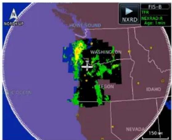
CONUS NEXRAD Regional NEXRAD
NEXRAD weather radar displays a mosaic of precipitation data, colored according to reflectivity. Composite reflectivity images depict the highest radar energy received from multiple antenna tilt angles at various altitudes. Base reflectivity images depict radar returns from the lowest antenna tilt angle. Per AC 00-63A, FIS-B CONUS and Regional NEXRAD are composite reflectivity images.
The precipitation intensity level reflected by each pixel represents the highest level of composite radar reflectivity data sampled in that location.
A clear understanding of ground-based Doppler weather radar capabilities will allow you to interpret the NEXRAD weather imagery in the safest way possible. The National Oceanic and Atmospheric Administration hosts a description of the technology on its website: https://www.weather.gov/jetstream/doppler_intro
RADAR DATA ANIMATIONS

To depict trending weather movements over time, an animation function stitches the last three to six received radar images together in sequence, from oldest to newest, and replays them on a continuous loop.
Play and stop controls are active when three or more images are available for playback.
CONNEXT PRECIP
Precipitation products are available for areas around the world. For current coverage areas and product information, visit www.garmin.com/connext.
FIS-B NEXRAD
FIS-B NEXRAD is uplinked to the aircraft as two separate weather products: CONUS and Regional NEXRAD. Both products display individually or simultaneously, separated by a white hash-marked boundary, based on source selection.
Depending on the locations of received FIS-B ground stations, Regional NEXRAD coverage can extend more than 250 nm around an aircraft's position. Aircraft flying at higher altitudes typically receive data from more ground stations than aircraft flying at low altitudes.
FIS-B NEXRAD does not differentiate between liquid and frozen precipitation types.

CONUS & Regional NEXRAD Combined
Missing Data Indications
A semi-transparent mask indicates regions where data may be missing or incomplete. Color is dependent upon the presence of topographical data.
The mask is purple when there is no underlying topographical data, such as on the FIS-B weather display, or on Map when the TOPO overlay is off.
On Map, the mask is dark gray when the TOPO overlay is on, so that the underlying topographical features can still be interpreted.
Source Options:
Source options are selectable from the FIS-B Weather menu or the NEXRAD key located in the control bar. The key label changes to reflect the active source.

CONUS
- Large, low-resolution weather image for the entire continental U.S.
- Pixels are 7.5 min (7.5 nm = 13.89 km) wide by 5 min (5 nm = 9.26 km) wide

Regional
- High-resolution weather image with limited range, centered around each broadcasting ground station
- Pixels are 1.5 min (1.5 nm = 2.78 km) wide by 1 min (1 nm = 1.852 km) tall
- Each weather pixel varies with latitude. Above 60° latitude, pixel block width doubles to 3 min/nm for regional maps

Combined
- Both CONUS and Regional NEXRAD images display simultaneously
• White hash mark indicates regional boundary
SIRIUSXM NEXRAD
SiriusXM offers NEXRAD radar imagery from CONUS and non-CONUS sources. Weather menu options are Composite and Base.

Depending on the SXM service and installed GDL hardware, radar base reflectivity imaging may have broader coverage within North America or be limited to only Canada.
Source Options:

Composite (CONUS)
Composite reflectivity image of radar for the conterminous U.S.

Base
Base reflectivity image. Coverage and availability are dependent upon subscription.
Precipitation above 52^ N may display as mixed precipitation regardless of actual precipitation type. Precipitation of an unknown type always displays as rain.
Textual AIRMETs

AVAILABLE WITH: SIRIUSXM | CONNEXT
An AIRMET advises of weather that may be particularly hazardous to single engine, light aircraft and VFR pilots. Overlays draw the geographical boundaries of received AIRMETs on the dedicated weather page.
SiriusXM Textual AIRMETs

Tapping an AIRMET opens a detailed report.

AIRMET TYPES

Icing
Areas of moderate airframe icing including areal extent.

Turbulence
Areas of moderate turbulence including vertical extent.

IFR
Weather conditions with ceilings <1,000 ft and/or visibility <3 mi.

MTN OBSR
Widespread mountain obscuration due to clouds, precipitation, smoke, haze, mist, or fog.

Surface Winds
Sustained surface winds >30 kt and/or potential non-convective wind shear below 2,000 ft AGL.
Graphical AIRMETs

AVAILABLE WITH: FIS-B
Graphical AIRMETs (G-AIRMETs) display more weather phenomena than textual AIRMETs, while eliminating the need to interpret raw text.
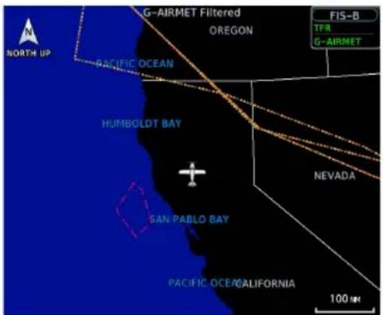
Tapping a G-AIRMET displays textual details.
Updates occur four times daily.
G-AIRMET:
Icing
Issued: 05-Nov 20:45 UTC
Active: 05-Nov 21:00 UTC
Expire: 06-Nov 00:00 UTC
Altitude: 17000 FT MSL
Filtering options allow you to mitigate page clutter. Forecast and filter selections are accessible from the FIS-B Weather menu.
Forecast Settings:
Off Current (Auto) All Forecasts
Disables automatic functionality.
Filter options not available.
Displays active graphical records based on the current UTC.
Function automatically switches from 0 hr to 3 hr forecasts.
Displays the most recent, non-expired graphical records.
Forecast periods include 0 hr, 3 hr, and 6 hr.
Hazard Awareness
G-AIRMET FILTERS
Freezing Level MTN OBSCR
Icing Surface Winds
IFR Turbulence
Low-level
Wind Shear
To enable graphical AIRMETs:
- Home > Weather > FIS-B Weather > Menu.
- Tap G-AIRMET and select between Current (Auto) and All Forecasts.
- Tap G-AIRMET Filters and select one or more filters.
AIREPs
AVAILABLE WITH: FIS-B | SIRIUSXM | CONNEXT

AIREPs are routine, automated reports of in-flight weather conditions such as wind and temperature.
SiriusXM AIREPs

AIREPs display as a green map icon. Tapping this icon displays a report.

Cell Movements
AVAILABLE WITH: SIRIUSXM

Information derived from NEXRAD displays the location of storm cells within a strong storm. Vector symbols represent cell position and direction of movement.
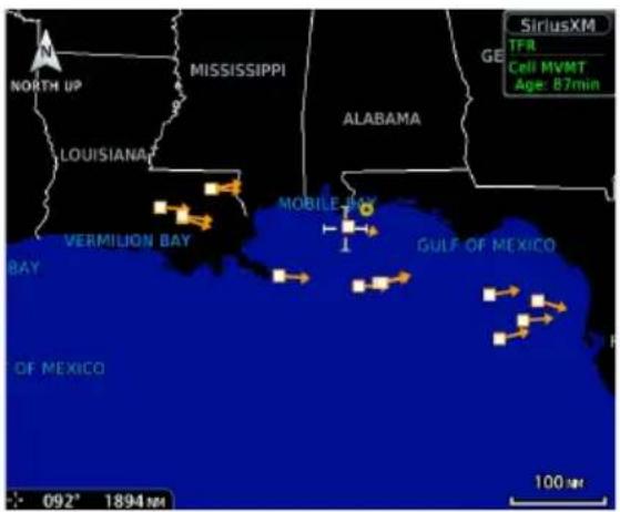
Tapping one of these symbols displays details about the cell's speed and direction as well as the storm's top altitude.
Cell Movement:
Speed: 17 KT
Direction: 102°T
Top: 21500FT
Top Heights
Top height is reported as maximum altitude of reflected precipitation. Storm height may be higher than radar reflections. Top heights are reported in MSL.
Center Weather Advisory

AVAILABLE WITH: FIS-B
These advisories communicate en route and terminal weather conditions expected to occur within the next two hours. Information is valid for up to 2 hours.
Tapping a CWA symbol displays textual details.
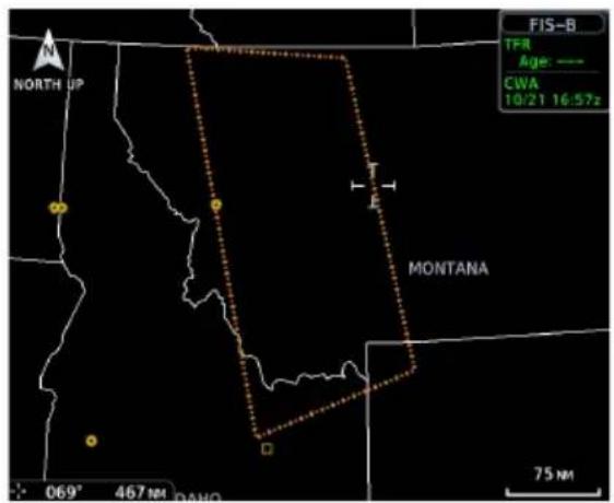
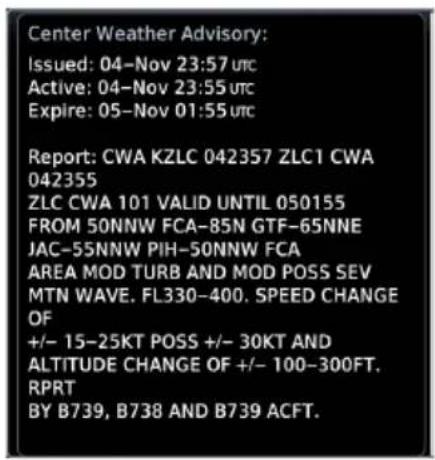
City Forecast

natural_image
Weather and weather icons including sun, cloud, rain, snowflake, moon, and smoke (no text or symbols)AVAILABLE WITH: SIRIUSXM
Provides two-day forecasts for major U.S. cities, including daily forecast high and low temperatures, chance of precipitation, and sky conditions.
City Forecast offers a 48 hour look ahead.

Tapping a City Forecast symbol displays weather details.

Forecast Period Options:
- Current • 12 hour • 24 hour • 36 hour • 48 hour
Clouds
CLOUD TOPS
AVAILABLE WITH:
FIS-B | SIRIUSXM

FIS-B Cloud Tops

Indicates the altitude of the highest visible portions of a cloud at the time of measurement.
- SiriusXM cloud top altitude data is estimated from IR satellite imagery
- FIS-B cloud top data is generated by a computer model and has limited accuracy compared to actual conditions
IR SATELLITE
AVAILABLE WITH: CONNEXT

Infrared Satellite weather information is available for North America and Europe. Updates occur every 30 minutes.
• Lighter grays depict colder temperatures
• Darker grays depict warmer temperatures
County Warnings

AVAILABLE WITH: SIRIUSXM
County warnings are provided for the counties within the continental United States. Specific public awareness and protection alerts, such as fires and natural disasters, are included with warnings for tornadoes, thunderstorms, floods and flash floods.

Tapping a County Warning symbol displays weather details.

Symbols include: • Severe T-Storm • Tornado • Flooding
Cyclone
AVAILABLE WITH: SIRIUSXM


Displays tropical storm information as issued by the National Hurricane Center. Includes the cyclone's location, projected path, date, and time.
Echo Tops
AVAILABLE WITH: SIRIUSXM

Freezing Levels
AVAILABLE WITH: FIS-B | SIRIUSXM
Depicts the location, elevation, and direction of NEXRAD radar echoes. This information is useful for gauging storm intensity in a relative sense. A higher radar echo means a stronger storm updraft.

SiriusXM Freezing Level

Color-coded contour lines indicate the altitude of the freezing level.
When freezing data is absent at a given altitude, it means:
- the system has not received data for the altitude, or
• the data is expired
FIS-B Weather:

To view freezing altitude, select the freezing level G-AIRMET. Updates occur four times daily.
Icing
AVAILABLE WITH:
FIS-B | SIRIUSXM


NOTE
Due to the incremental and overlapping nature of the FIS broadcast, timestamps, regional coverage, and map data availability may vary with altitude for computer generated FIS-B icing forecasts.
FIS-B Icing

Icing potential provides a graphic view of current icing conditions. SLD threat areas are depicted as black and pink blocks over the icing colors.
Directional keys allow you to adjust the reporting altitude within product-specific limits.
FIS-B SIRIUSXM
| Timestamp shows: | Valid time in UTC | Time of data compilation |
| Altitude Range: | 2,000 to 24,000 ft (at 2,000 ft intervals) | 1,000 ft3,000 ft6,000 ft9,000 to 30,000 ft (at 3,000 ft intervals) |
ICING CATEGORIES
 | SLD Threat | Categories vary depending on the configured weather source. |
 | Heavy | |
 | Moderate | Icing potential is not a forecast, but a presentation of icing potential at the time of analysis. Supercooled Large Droplet (SLD) icing conditions are characterized by the presence of relatively large, super cooled water droplets indicative of freezing drizzle and freezing rain aloft. |
 | Light | |
 | Trace1 | |
 | No Coverage2 |
Lightning
AVAILABLE WITH: FIS-B | SIRIUSXM | CONNEXT

SiriusXM Lightning
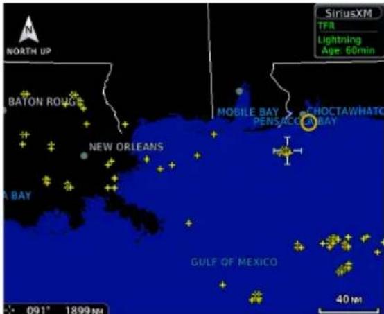
SiriusXM Weather:
A yellow cross icon indicates a strike event occurring within a two kilometer region. Strike location is an estimate of its center.
Unlike Stormscope, the icon does not change shape or color as data ages.
Connext Weather:
Only cloud-to-ground strikes are reported through the Connext weather service.
FIS-B Weather:

Lightning strikes display as a bolt or cluster of bolts. The bolt color indicates the strike polarity.
METARs and TAFs

AVAILABLE WITH: FIS-B | SIRIUSXM | CONNEXT
METAR and TAF reports provide information on current and forecast conditions. Colored METAR flags display when a METAR reporting station is matched with a corresponding navigation database identifier.
When selected, the METAR is decoded and displayed above the original METAR text. METARs are provided only in areas covered by the currently loaded navigation database.
Tapping a METAR opens a detailed report.
FIS-B METARS


METAR SYMBOLS

VFR
Ceiling greater than 3,000 ft AGL and visibility greater than five miles.

Marginal VFR
Ceiling 1,000 to 3,000 ft AGL and/or visibility three to five miles.

IFR
Ceiling 500 to 1,000 ft AGL and/or visibility one to three miles.

Low IFR
Ceiling below 500 ft AGL and/or visibility less than one mile.

Unknown
Ceiling and/or visibility data unavailable.
PIREPs
AVAILABLE WITH: FIS-B | SIRIUSXM | CONNEXT

PIREPs are pilot-generated weather reports that may contain non-forecast adverse weather conditions, such as low in-flight visibility, icing conditions, wind shear, and turbulence.
FIS-B PIREPs

Selecting a PIREP displays a report.
![PIREP: Location: PDX 45 NM 79° Time: 23:53 UTC [ Age: 19 hrs ] Urgent: No AC Type: CRJ Altitude: 10000 FT Turbulence: MO Remarks: ..ZSE Report: PIREP PDX 022353Z PDX UA /OV PDX079045/TM 2353/FL100/TP CRJ/TB MO /RM ..ZSE](/content/2026/06/1343935/images/a590a72502b0bc9bf0b6fab12a754bead8c282e959bfdd35e0fe5b80a82eae94.jpg)
PIREP SYMBOLS

flowchart
graph TD
    A["Blue Square"] --> B["Routine (UA)"]
    C["Yellow Square"] --> D["Urgent (UUA)"]
    E["Yellow Square"] --> F["Route"]
    G["Blue Square"] --> H["Route"]
PIREPs are issued as either Routine (UA) or Urgent (UUA). Tapping a PIREP symbol displays textual details.
SIGMETs

AVAILABLE WITH: FIS-B | SIRIUSXM | CONNEXT
The SIGMET overlay draws the geographical boundaries of received SIGMETs on the dedicated weather page. Convective and non-convective SIGNificant METerological Information combine in a textual report and display graphically for the observed or forecast region.
SiriusXM SIGMETs & AIRMETs

Tapping a SIGMET opens a detailed report.
SIGMET: Report: CONVECTIVE SIGMET 36WVALID UNTIL 1955ZWAFROM 30SSE YDC-40NW EPHDVLPG LINE TS 30 NM WIDE MOV FROM 25020KT. TOPS TO FL340..
Surface Analysis

AVAILABLE WITH: SIRIUSXM

Displays weather fronts, high (H) and low (L) pressure centers, and isobars.
Forecast Period Options:
- Current • 12 hour • 24 hour
• 36 hour • 48 hour
TFRS
AVAILABLE WITH: FIS-B | SIRIUSXM | CONNEXT


WARNING
Do not exclusively use datalink services for TFR information. TFR Depictions may not be a complete listing and may vary between cockpit devices. Always confirm TFR information with official sources such as Flight Service Stations or Air Traffic Control.
TFRs identify areas of airspace where aircraft are temporarily restricted from operating. They are routinely issued for occurrences such as dignitary visits, military activities, and forest fires.
Tapping a TFR displays textual details.
FIS-B TFRs


FIS-B Weather:
Latest TFR data transmit every 10 to 20 minutes.
For FIS-B datalink weather, TFRs and NOTAMs that do not include geographical locations are viewable from the FIS-B Raw Text Reports page.
Turbulence
AVAILABLE WITH:
FIS-B | SIRIUSXM

natural_image
Pixelated orange abstract shape resembling a stylized bird or creature (no text or symbols)
NOTE
Due to the incremental and overlapping nature of the FIS broadcast, timestamps, regional coverage, and map data availability may vary with altitude for FIS-B turbulence forecasts.
FIS-B Turbulence

Turbulence data identifies the potential for erratic movement of high-altitude air mass associated winds. This information is intended to supplement AIRMETs and SIGMETs.
Turbulence is classified as light, moderate, severe or extreme.
Directional keys allow you to adjust the reporting altitude within product-specific limits.
FIS-B SIRIUSXM
| Timestamp shows: | Valid time in UTC | Time of data compilation |
| Altitude Range: | 2,000 to 24,000 ft (at 2,000 ft intervals) | 21,000 to 45,000 ft (at 3,000 ft intervals) |
Data may not be available for all regions at all altitudes.
Winds Aloft
AVAILABLE WITH: FIS-B | SIRIUSXM | CONNEXT

SiriusXM Winds Aloft

Indicates wind speed and direction, and temperature forecast for the specified altitude.
The wind barb extends outward from the reporting location dot in the direction of wind origination.
Directional keys allow you to adjust the reporting altitude within product-specific limits. Reporting altitudes vary depending on the weather provider.
FIS-B Winds & Temps Aloft
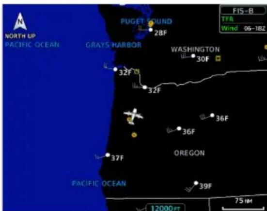
FIS-B Winds & Temperatures Aloft:
FIS-B wind forecasts also provide temperature data for the selected altitude. These forecasts update every 12 hours.
Altitude Range:
| FIS-B SIRIUSXM & CONNEXT | |
| 1,000 ft | Surface to 45,000 ft (at 3,000 ft intervals) |
| 1,500 ft | |
| 2,000 ft | |
| 3,000 ft | SiriusXM data not available at 45,000 ft |
| 6,000 ft | |
| 9,000 ft | |
| 12,000 ft | |
| 15,000 ft | |
| 18,000 ft | |
| 24,000 ft | |
| 30,000 ft | |
| 34,000 ft | |
| 39,000 ft | |
| 45,000 ft | |
| 53,000 ft | |
Not all altitudes provide winds and temperatures aloft forecasts for all regions.
SiriusXM Weather

SiriusXM satellites deliver high bandwidth (S-band) data to provide high-resolution images. Available data is received within a few minutes after the aircraft satellite receiver comes into view of the SiriusXM satellite network.
FEATURE REQUIREMENTS
• SiriusXM receiver (GDL 69 or GDL 69A)
• Active SiriusXM Aviation Weather subscription
FEATURE LIMITATIONS
- For Icing Potential, Winds Aloft (U.S.), and Turbulence, the valid time displays instead of product age
- For Freezing Level and Winds Aloft (Canada), the generation time displays instead of valid time
Activate SiriusXM Services
Before you can access SiriusXM Weather, you must contact SiriusXM customer service and provide them with either one or two coded IDs:
• Data Radio ID (Weather)
• Audio Radio ID (Entertainment).
These coded IDs are used to send an activation signal, which allows the use of weather and entertainment products received by the GDL 69/69A.
When SiriusXM weather services are not activated:
- All weather product boxes are cleared on the GDL 69 Status page
- A yellow "Activation Required" message appears at the center of the page
Service Class refers to the groupings of weather products available for subscription.
SiriusXM Customer Service: https://www.siriusxm.com/sxmaviation.
COMPLETE SUBSCRIPTION ACTIVATION
- Contact SiriusXM using the customer service telephone number listed on the website.
- Provide the customer service agent with your Data Radio ID and Audio Radio ID.
-
Position aircraft within the satellite reception area and power on the unit.
-
Navigate to the GDL 69 Status page.
-
From the Home page: Tap System > External LRUs, locate GDL 69 and tap More Info.
• From the Music page: Tap Status. -
Verify activation. For weather subscriptions, the status page displays your Data Radio ID, Subscription Level, and a list of weather products.
-
Tap Menu > Lock Activation > OK.
Troubleshooting the GDL 69/69A Datalink Receiver
GTN serves as the control head for your remotely mounted GDL 69/69A. In the event of a receiver failure:
• View datalink receiver status on the GDL 69 Status page
- Verify the SiriusXM Satellite Radio subscription is active
- Check circuit breakers to ensure power is applied to the receiver
It may take several minutes for all subscription data to become available after unit power up.
For more information, consult GDL 69/69A SiriusXM Satellite Radio Activation Instructions. For subscription activation instructions, visit https://www.siriusxm.com/sxmaviation.
SiriusXM Weather Setup
SiriusXM Weather Menu

flowchart
graph TD
    A["NEXRAD"] --> B["Forecast Period"]
    C["Echo Tops"] --> B
    D["Cloud Tops"] --> B
    E["Icing"] --> B
    F["Turbulence"] --> B
    G["Winds Aloft"] --> B
    H["Current"] --> I["12 Hour"]
    I --> J["24 Hour"]
    J --> K["36 Hour"]
    K --> L["48 Hour"]
    M["City Forecast"] --> N["Surface Analysis"]
    O["Lightning"] --> P["METAR"]
    Q["Cell Movement"] --> R["AIREP PIREP"]
    S["County Warnings"] --> T["SIGMET AIRMET"]
    U["Freezing Level"] --> V["Cyclone"]
    W["Orientation"] --> X["North Up"]
    W --> Y["Track Up"]
    W --> Z["Heading Up"]
    AA["Legend"] --> AB["End"]
Tap Menu to access weather product overlay controls and pilot settings.
Changes to an overlay setting take effect immediately.
- Enable/disable weather overlays
- Specify a forecast period
- Change the orientation of the weather display
• Display the product legend
Map WX Overlays
SiriusXM Weather overlay controls reside in the Map Setup menu.
From the Home page, tap Map > Menu, Map Setup, and select the Weather tab.
If another weather source is active, tap Weather Source and select SiriusXM.
FIS-B Weather
FIS-B weather data displays on the dedicated weather page and as overlays on Map. No pilot action is required to receive FIS-B weather information.
FEATURE REQUIREMENTS
• UAT receiver (GDL 88 or GTX 345)
The FAA provides FIS-B as a Surveillance and Broadcast Service operating on the UAT (978 MHz) frequency band. FIS-B uses a network of FAA-operated ground-based transceivers to transmit weather datalink information to the aircraft's receiver on a scheduled continuous basis.
The Flight Information Service-Broadcast (FIS-B) Weather service is freely available for aircraft equipped with a capable datalink universal access transceiver (UAT). Ground stations provide uninterrupted services for the majority of the contiguous U.S., Hawaii, Guam, Puerto Rico, and parts of Alaska. No weather subscription service is required. For the latest FAA ground station coverage information, visit: www.faa.gov/nextgen/programs/adsb/
Data Transmission Limitations
FIS-B broadcasts provide weather data in a repeating cycle which may take several minutes to completely transmit all available weather data. Therefore, not all weather data may be immediately present upon initial FIS-B signal acquisition.
LINE OF SIGHT RECEPTION
To receive FIS-B weather information, the aircraft's datalink receiver must be within range and line-of-sight of an operating ground-based transceiver. Reception may be affected by altitude, terrain, and other factors. Per the FAA, much of the United States has FIS-B in airborne coverage at and above 3,000 feet AGL. Terminal coverage is available at altitudes below 3,000 feet AGL and is available when flying near approximately 235 major U.S. airports. Surface coverage allows FIS-B ground reception at approximately 36 major U.S. airports.
PER FAA TSO-C157B
FIS-B information may be used for pilot planning decisions focused on updating the pilot's awareness of the dynamic flight environment; including avoiding areas of inclement weather that are beyond visual range and pilot near-term decisions where poor visibility precludes visual acquisition of inclement weather. FIS-B weather and NAS status information may be used as follows:
a. To promote pilot awareness of ownership location with respect to reported weather, including hazardous meteorological conditions; NAS status indicators to enhance pilot planning decisions; and pilot near-term decision-making.
b. To cue the pilot to communicate with Air Traffic Control, Flight Service Station specialist, operator dispatch, or airline operations control center for general and mission critical meteorological information, NAS status conditions, or both. FIS-B information, including weather information, NOTAMs, and TFR areas, are intended for the sole purpose of assisting in long-/near-term planning and decision making. The system lacks sufficient resolution and updating capability necessary for aerial maneuvering associated with immediate decisions. In extreme scenarios, the oldest weather radar data on the display can be up to 15 to 20 minutes older than the display's age indication for that weather radar data. Therefore, do not attempt to use FIS-B weather information to maneuver the aircraft at minimum safe distances from hazardous weather.
FIS-B information must not be used in lieu of a standard preflight briefing.
c. FIS-B uplink is a subscription-free FIS broadcast managed by FAA SBS. It provides an FAA approved source for METAR, TAF, WINDS, PIREPs, NEXRAD, AIRMET, SIGMET, and TFR information, and is subject to the broadcast range limits for these products.
FIS-B uplink is not an FAA approved source for NOTAMs.
NOTAM 30-DAY LIMITATION
NOTAMs received via FIS-B may not be a complete listing. Active NOTAMs are removed from the FIS-B data stream 30 days after issuance. Before flight, review all necessary aeronautical and meteorological information from official sources.
For more information, consult AC 00-63A or latest revision.
FIS-B Product Status

View the status of all FIS-B weather products. States include:
- Unavailable
- Awaiting Data
- Data Available
You may access this page one of two ways.
From the External LRUs list:
Home > System > External LRUs, locate GDL 88 or GTX 345, and tap More Info
From the FIS-B Weather menu:
Home > Weather > FIS-B Weather > Menu > Datalink Status
FIS-B WEATHER ENABLED
To mitigate any possibility of the avionics receiving unexpected data formats in the FIS broadcast, you may disable FIS-B Weather by toggling the Enabled key to off.
This key is active by default. It is not intended for use under normal broadcast conditions.
FIS-B Weather Setup
FIS-B Weather Menu
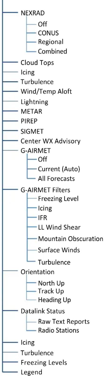
flowchart
graph TD
    A["NEXRAD"] --> B["Off"]
    A --> C["CONUS"]
    A --> D["Regional"]
    A --> E["Combined"]
    F["Cloud Tops"] --> G["Icing"]
    F --> H["Turbulence"]
    F --> I["Wind/Temp Aloft"]
    F --> J["Lightning"]
    F --> K["METAR"]
    F --> L["PIREP"]
    F --> M["SIGMET"]
    F --> N["Center WX Advisory"]
    O["G-AIRMET Filters"] --> P["Off"]
    O --> Q["Current (Auto)"]
    O --> R["All Forecasts"]
    S["G-AIRMET Filters"] --> T["Freezing Level"]
    S --> U["Icing"]
    S --> V["IFR"]
    S --> W["LL Wind Shear"]
    S --> X["Mountain Obscuration"]
    S --> Y["Surface Winds"]
    S --> Z["Turbulence"]
    AA["Orientation"] --> AB["North Up"]
    AA --> AC["Track Up"]
    AA --> AD["Heading Up"]
    AE["Datalink Status"] --> AF["Raw Text Reports"]
    AE --> AG["Radio Stations"]
    AH["Icing"] --> AI["Turbulence"]
    AH --> AJ["Freezing Levels"]
    AH --> AK["Legend"]
Tap Menu to access weather product overlay controls and pilot settings. Changes to an overlay setting take effect immediately.
- Enable/disable weather overlays
- Select a NEXRAD source
- Filter G-AIRMETs and specify a forecast period
- Change the orientation of the weather display
• View datalink status and enable/disable the FIS-B Weather function
• Display the product legend
The Datalink Status page provides controls for enabling/disabling the FIS-B Weather function, viewing raw text reports, and checking ground reception status.
Map WX Overlays
FIS-B Weather overlay controls reside in the Map Setup menu.
From the Home page, tap Map >
Menu > Map Setup, and select the Weather tab.
If another weather source is active, tap Weather Source and select FIS-B.
Raw Text Reports
Product Selections

View raw textual data for a FIS-B product.
- Open the FIS-B WX Status page.
- Tap Raw Text Reports.
- Select a weather product.


The latest uploaded data for the product displays on a dedicated page.


Multiple reporting stations appear in a list. Tapping View displays raw text for the corresponding identifier.

| FIS-B SERVICE OUTAGE 210201Z ZBW,ZDC,ZJX,ZMA,ZME,ZNY,ZTL GUAM NEXRAD PRODUCT UPDATES UNAVAILABLE |
| FIS-B SERVICE OUTAGE 221321Z ZLC SUA PRODUCT UPDATES UNAVAILABLE |
| FIS-B SERVICE OUTAGE 212200Z ZJX,ZMA,ZDC SAN JUAN NEXRAD PRODUCT UPDATES UNAVAILABLE |
To view information about products not available due to a service outage, select Unavailable Products.
READING WINDS/TEMPS ALOFT REPORTS
Tapping Winds/Temps Aloft displays a forecast of winds and temperatures for different altitudes. Temperature forecasts are not included for altitudes below 2,500 ft AGL.
On the raw text report, altitude values do not align with the corresponding forecast. Match the color of the altitude and forecast to interpret the information.
Color markings are for reference only.
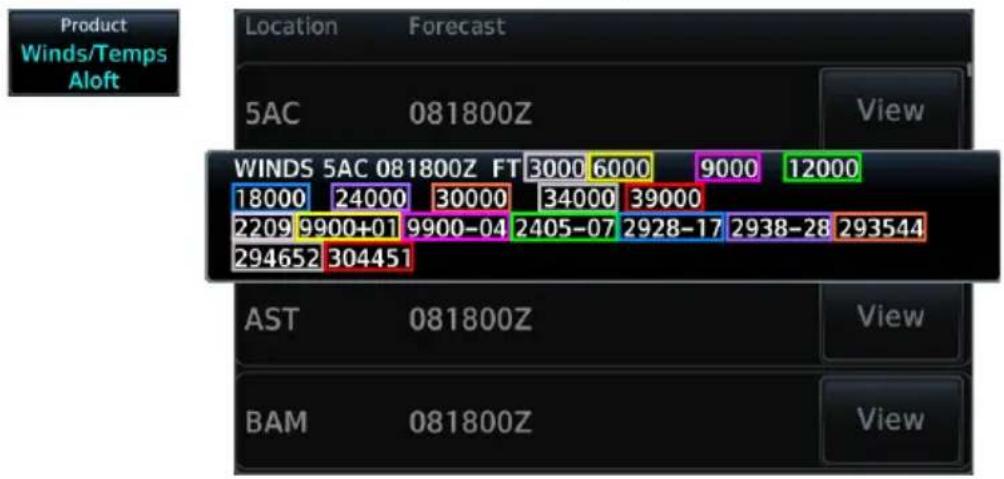
ALTITUDE (FT)
3,000 6,000 9,000 12,000 18,000 24,000 30,000 34,000 39,000 2209 9900+01 9900-04 2405-07 2928-17 2938-28 293544 294652 304451
FIS-B Ground Reception Status

Monitor FIS-B ground station transmission status from the FIS-B Reception Status page.

Current Report List shows the completeness of NOTAM-TFR, AIRMET, and SIGMET data for all received ground stations.
Station Range field indicates complete/incomplete status for only the products within the received ground station's range.
OPEN FIS-B RECEPTION STATUS PAGE

This page is accessible from the Datalink Weather menu. You can access this menu one of two ways:
From FIS-B Weather:
Tap Menu > Datalink Status > Menu > Radio Stations.
From the External LRU list:
Home > System > External LRUs > Locate GDL 88 and tap More Info > Datalink Status > Menu > Radio Stations.
Connext Weather

Garmin provides Connext datalink, on-demand weather products through the Iridium satellite system via a GSR 56 transceiver and L-band frequencies. An Iridium satellite data subscription service is required for worldwide Connext weather coverage.
FEATURE REQUIREMENTS
• GSR 56 transceiver
• Active Connex t subscription
Connext Weather coverage is available throughout most of Europe, Canada, and the U.S. Additional radar coverage areas are added continuously. Various world-wide weather subscription package options provide weather reporting for most of Europe, Canada, Australia, and the U.S.
For the latest radar coverage information, visit: https://fly.garmin.com/fly-garmin/connext/worldwide-weather/
Activate Connext Satellite Services
To access Connext Weather, visit flyGarmin.com and create a Connext Satellite Services account. Garmin will issue an access code for entry in the Connext Registration pop-up.
When completing your application for Connext Satellite Services, be ready to provide the following information.
• GTN ID
- Iridium serial number
- Airframe info:
- Model
- Tail number
- Serial number
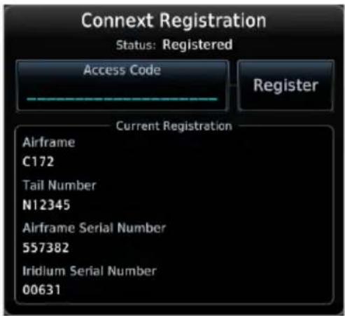
If access code and system ID are correct, the airframe registration details will display.
Current Registration Detail
To complete activation:
- Move aircraft within satellite range and power on the unit.
- Tap Weather > Connext Weather > Menu > Connext Settings > Datalink Status > Connext Registration > Access Code.
- Enter the required code, then tap Register.
Deactivate Connext Unit Registration
You can deactivate your registration by entering an invalid access code in the Connext Registration pop-up window. This prevents the unit from making any further requests from Connext. Requests made after deactivation will fail.
From the GSR Status page:
- Tap Connext Registration > Access Code.
- Tap CLR to remove the current access code.
- Enter an invalid code, then tap Register.
Deactivating your Connext registration does not cancel your subscription.
Connext Weather Setup
Connext Weather Menu
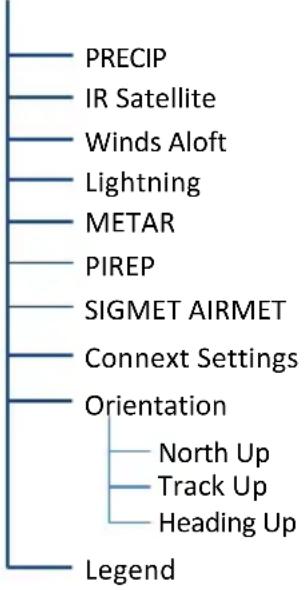
flowchart
graph TD
    A["PRECIP"] --> B["IR Satellite"]
    B --> C["Winds Aloft"]
    C --> D["Lightning"]
    D --> E["METAR"]
    E --> F["PIREP"]
    F --> G["SIGMET AIRMET"]
    G --> H["Connext Settings"]
    H --> I["Orientation"]
    I --> J["North Up"]
    I --> K["Track Up"]
    I --> L["Heading Up"]
    I --> M["Legend"]
Tap Menu to access weather product overlay controls and pilot settings. Changes to an overlay setting take effect immediately.
- Enable/disable weather overlays
• View Iridium satellite datalink status and signal strength - Change the orientation of the weather display
• Display the product legend
Tap Connext Settings to access the Data Request function and various coverage region options. From here you may access the GSR Status page, where the Connext Registration function resides.
Connext Settings Menu

flowchart
graph TD
    A["Present Position"] --> B["Destination"]
    B --> C["Flight Plan"]
    C --> D["Specify distance"]
    C --> E["Waypoint"]
    E --> F["Specify identifier"]
    C --> G["Request Data"]
    G --> H["COV Diameter"]
    H --> I["Select coverage diameter"]
    C --> J["Datalink Status"]
    J --> K["Connex registration"]
Map WX Overlays
Connext Weather overlay controls reside in the Map Setup menu.
From the Home page, tap Map > Menu > Map Setup, and select the Weather tab.
If another weather source is active, tap Weather Source and select Connext.
Connext Data Requests
FEATURE REQUIREMENTS
- Direct connection to GSR 56 (Auto Request function)
Download selected weather products for a specific waypoint, flight plan, destination, or your current position. A request must be sent in order for downloading to occur.
WHERE TO FIND IT

Weather data request controls reside in the Connext Settings menu.
Requests may be sent manually or set to occur automatically within a specified time interval.
DATA REQUEST CONTROLS
Request Data
Request Data
Request weather data at any time regardless of predetermined automatic update frequency.
Once the request is sent, you may reset the Auto Request timer (if active) for the next request interval.
Auto Request 10 MIN
Auto Request
Select a weather request period to enable automatic updates.
Options: • Off • 5 min • 10 min
00:14 Remaining...
A timer counts down to the next update. The Cancel Request key becomes available.
Multiple Weather Requests
To accommodate multiple weather requests, Connext merges the following products with stale data, while discarding the stale data of other products.
- AIRMETs
METARs
• SIGMETs
• TAFs
• TFRs
Use these controls when you want to:
- Set automatic updates: Tap Auto Request and select the automatic weather request period.
- Request a manual update: Tap Menu > Connext Settings > Request Data.
- Cancel a request in progress: Tap Cancel Request.
COVERAGE REGION OPTIONS
| Present Position | Request weather information around aircraft's present position. COV diameter determines extent of request. |
| Destination | Request weather information for the destination airport. |
| Flight Plan | Request weather information for the active fight plan route. |
| Distance | Enter requested weather information for a specified distance along the active flight plan.Range: 10 nm to 500 nm |
| Waypoint | Request weather information for a specified waypoint. |
| COV Diameter | Define the diameter of coverage.Range: 10 nm to 500 nm |
GTN 650Xi SERIES
| Coverage Region |
Coverage region controls reside in a dedicated submenu.
Tap Menu > Connext Settings > Coverage Region.
Stormscope

Stormscope lightning information displays on a dedicated weather page and as overlays on Map.

WARNING
Do not exclusively use the lightning detection system for weather avoidance. The system may display inaccurate or incomplete information. For additional information, consult the lightning detection system documentation.
FEATURE REQUIREMENTS
• WX-500 Stormscope Weather Mapping Sensor
FEATURE LIMITATIONS
- Stormscope lightning information cannot display concurrently with a datalink lightning weather product (SiriusXM, Connex, or FIS-B)
Stormscope Features
• Passive weather avoidance system
- Detects electrical discharges from thunderstorms within 200 nm of current position
- Plots strike count and relative bearing location every two seconds
• Heading and distance from aircraft
- Arc and 360^ viewing options
For more information, consult the WX-500 pilot's guide.
Stormscope Setup

flowchart
graph TD
    A["Stormscope Menu"] --> B["View"]
    A --> C["Mode"]
    B --> D["360° Arc"]
    C --> E["Cell Strike"]
Tap Menu to access Stormscope setup options.
From here, you can change the current display view and mode settings.
Changes in mode selection also reflect on the associated Map overlay.
Stormscope Map Overlay
Stormscope overlay controls reside in the Map menu.
From the Home page, tap Map > Menu > Stormscope.
Changes in overlay mode selection also reflect on the Stormscope display. The same is true for clearing strikes on Map.
Stormscope Modes & Symbols
Cell Mode Strike Mode
Identifies clusters of electrical activity, grouping individual strikes together.
Displays individual discharge points in relation to where they are detected.
When to use:
During heavy storm activity to identify where storm cells are located.
When to use:
During periods of light electrical activity to plot the initial strikes associated with a building thunderstorm.

Less than 6 strikes (initial strike)

Less than 60 strikes

Less than 120 strikes Less than 180 strikes
Strike Rate
Strike Rate reports the approximate number of strikes per minute for a given view range. Refer here when trying to determine if storm cells are building or decaying.

Strikes occur at a higher rate as a storm matures. They are less frequent as the storm dissipates.
CLEAR STRIKES

Tapping this key resets the rate value and clears the display of all strikes. Clearing strikes on the Stormscope display also clears them on Map.
Stormscope data displays with or without a heading source. If flying without a heading source, you must clear all strikes following each heading change
Views
Stormscope provides both arc and 360° views of lightning data.
ARC VIEW
Cell Mode Strike Mode
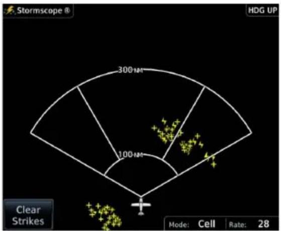

360^ VIEW
Cell Mode Strike Mode
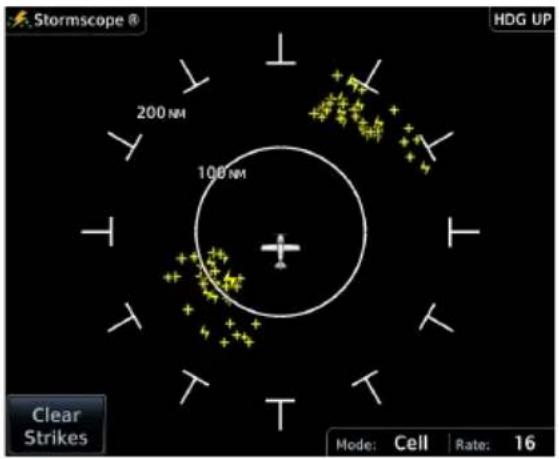

Stormscope Display Orientation
Heading Up is the normal display orientation. If no heading source is available, the page orientation label changes to "HDG N/A."
Airborne Weather Radar
AVAILABLE WITH: GTN 750Xi SERIES

Weather radar information displays on a dedicated weather page and as overlays on Map.

WARNING
Use weather radar to avoid severe weather, not to enter it.
FEATURE REQUIREMENTS
• GTN 725Xi or GTN 750Xi
FEATURE LIMITATIONS
• Available modes and intensity levels depend on the installed radar type
• Not available on GTN 650Xi Series units
Maximum Permissible Exposure Level, GWX 68
Radiation exceeds the U.S. Government standard level of 1 mW/cm ^2 11 feet from the antenna. All personnel must a minimum safe distance while the radar is in operation.
Average power density at the MPEL boundary significantly reduces with a scanning or rotating beam.
For information on safe distance determination, refer to Advisory Circular 20-68B.
For maximum permissible exposure levels, consult the appropriate radar documentation.
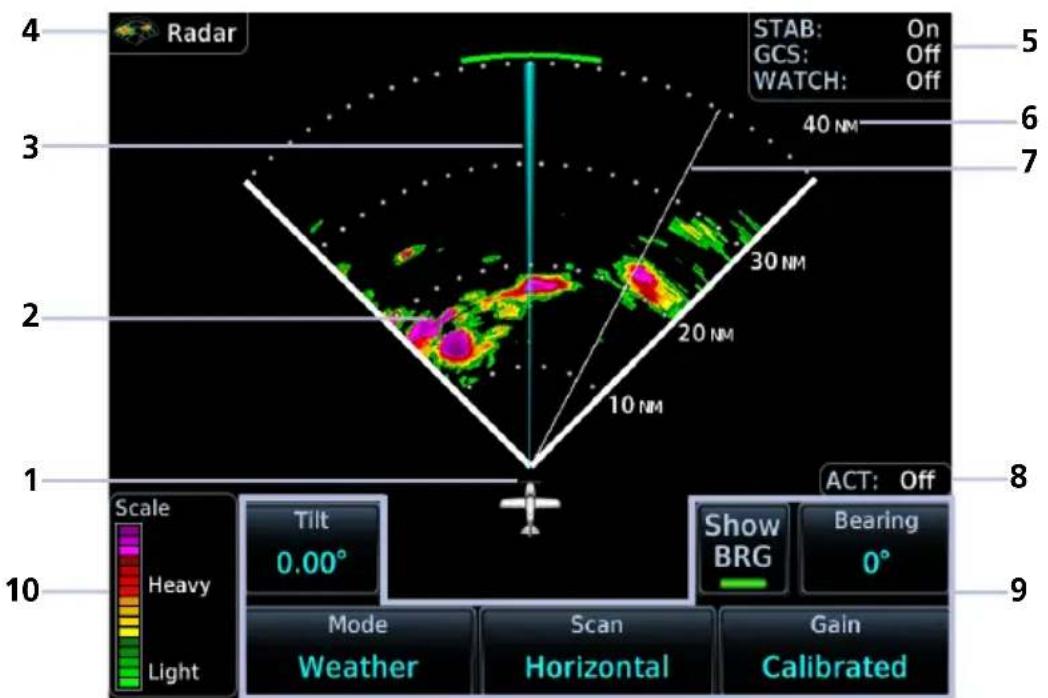
Weather Radar Features
| 1 Ownership Icon 6 Radar Display Range | |
| 2 Weather Depiction 7 Scan | |
| 3 Bearing/Tilt Line 8 ACT Status Field | |
| 4 WX App Label 9 Radar Controls | |
| 5 Feature Status Display 10 Intensity Scale |
RADAR UNITS

Distance units on the radar display are determined by the pilot selectable Distance/Speed setting in the System Units app (Home > System > Units > Distance/Speed).
DISPLAY ADJUSTMENTS

Tapping In and Out changes the radar display range.
TILT AND BEARING ADJUSTMENTS
To adjust tilt and bearing angle, tap and drag the line indicator as necessary, or use the associated control keys.
INTENSITY SCALE


Each operating mode uses a unique color palette to depict increasing intensity levels.
Weather Ground
WARM-UP COUNTDOWN TIMER

A warm-up period initiates upon power up (GWX 68 only). Duration varies depending on how long the radar is off. The radar begins transmitting once warm-up is complete.
Weather Radar Setup
Weather Radar Menu
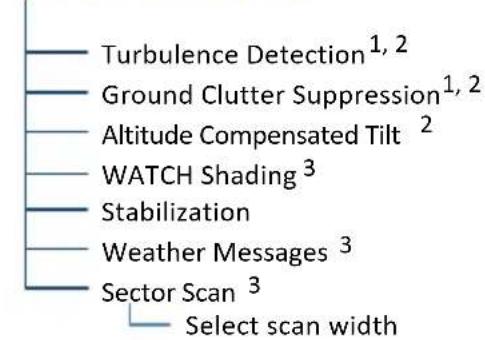
flowchart
graph TD
    A["Turbulence Detection¹,²"] --> B["Ground Clutter Suppression¹,²"]
    B --> C["Altitude Compensated Tilt²"]
    C --> D["WATCH Shading³"]
    D --> E["Stabilization"]
    E --> F["Weather Messages³"]
    F --> G["Sector Scan³"]
    G --> H["Select scan width"]
Tap Menu to access weather radar setup options. Available features are dependent upon configuration.
With the exception of Sector Scan, all selections are on/off only.
Map WX Overlays
The Radar overlay control resides in the Map Setup menu.
From the Home page, tap Map > Menu > Radar.
Radar and NEXRAD overlays are mutually exclusive. Selecting one automatically turns the other off.
^1 Requires feature enablement.
^2 GWX 70/75/80 only.
^3 Not available for third-party radars.
ALTITUDE COMPENSATED TILT
AVAILABLE WITH: GWX 70/75/80
FEATURE LIMITATIONS
• Not available for third-party radars
This feature adjusts the tilt to compensate for altitude changes as the aircraft climbs and descends.
Status displays above the radar controls.
AVAILABLE WITH: GWX 70/75/80
FEATURE REQUIREMENTS
• Purchased GWX Ground Clutter Suppression feature enabled on unit
FEATURE LIMITATIONS
• Not available for third-party radars
• Horizontal scans only
This feature reduces the amount of returns of highly reflective objects on the ground, while maintaining the intensity and size of weather returns.
SECTOR SCAN
FEATURE LIMITATIONS
• Not available for third-party radars
• Horizontal scans only
The sector scan option focuses the scan on a smaller segment of the radar sweep. This is useful when monitoring priority weather targets.
| GWX INCREMENTS |
| 68 20°, 40°, 60°, Full |
| 70/75/80 20°, 40°, 60°, 90°, Full |
| The 90° horizontal scan option is available only for radars with extended scan capabilities (120° sweep). |
Horizontal sector scans center on the bearing line.
Increments vary according to radar.
STABILIZATION
This feature helps stabilize the antenna so the scan is parallel to the ground when active. When off, the antenna scan is relative to the aircraft lateral axis.
TURBULENCE DETECTION
AVAILABLE WITH: GWX 70/75/80
FEATURE REQUIREMENTS
• Purchased GWX Turbulence Detection feature enabled on unit
FEATURE LIMITATIONS
• Not available for third-party radars
• Horizontal scans only
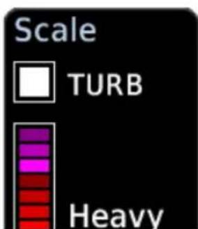
This feature detects and displays severe turbulence.
A legend shows when turbulence detection is active. Status reports as inactive when:
• Current scan range is greater than 160 nm
• Radar is not in weather mode
• Vertical scan is active
Turbulence Off Turbulence On


The decision to fly into an area of radar targets depends on target intensity, spacing between targets, aircraft capabilities, and pilot experience.
Some weather radars detect only precipitation, not clouds or turbulence. While GTN may indicate clear areas between intense returns, this does not mean it is safe to fly between them.
WATCH
FEATURE LIMITATIONS
• Not available for third-party radars
• Horizontal scans only
Use WATCH to determine areas of inaccuracies in displayed intensity from attenuation while in horizontal scan mode. Adjust tilt to determine the extent of attenuation in a shaded area. WATCH displays only in horizontal scans.
WATCH Off WATCH On


WEATHER MESSAGES
FEATURE LIMITATIONS
• Not available for third-party radars
• Not available during ground mode
• Horizontal scans only
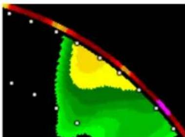
natural_image
Color-coded thermal or emission profile image with red, yellow, green, and purple regions against black background (no text or symbols)These alerts indicate the presence of heavy precipitation beyond the current display range (80 nm to 320 nm from current position).
Red bands on the outer range ring display at the approximate azimuth of severe weather targets.
- If the antenna tilt is adjusted too low, a weather alert is generated by ground returns.
- If a weather alert is detected within +10 degrees of the aircraft heading, an advisory displays in the message list.
Radar Modes

WARNING
Do not transmit when personnel or objects are within 11 feet of the antenna.

Tapping Mode opens a list of available mode options.

A confirmation pop-up alerts you when attempting to scan while on the ground.
STANDBY
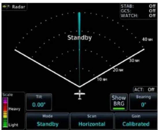
- Parks the antenna at the centerline
• Automatic standby occurs during power up and landing
During weather and ground modes, the system automatically switches to standby upon landing.
TEST
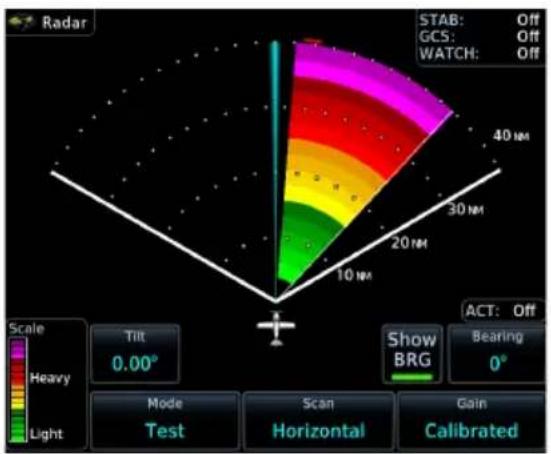
- Places transmitter in standby as the display simulates a radar sweep
• Data verifies communication between the weather radar and display - Radar pulses do not transmit from the antenna during this mode
GROUND

- Presents a depiction of terrain similar to that of a topographical map
- Useful when trying to verify aircraft position
| GROUND MAP MODE COLOR | GROUND TARGET INTENSITY LEVELS | |
| GWX RADAR INTENSITY | THIRD-PARTY RADAR LEVEL | |
| Black 0 dB 0 | ||
| Light Blue > 0 dBZ to < 9 dBZ 1 | ||
| Yellow 9 dBZ to < 18 dBZ 2 | ||
| Magenta 18 dBZ to < 27 dBZ 3 and above | ||
| Blue 27 dBZ and greater Not used | ||
WEATHER
• Presents an airborne depiction of precipitation
- Colors represent approximate rainfall intensity and rates for weather radar targets.
GWX 68 Radar
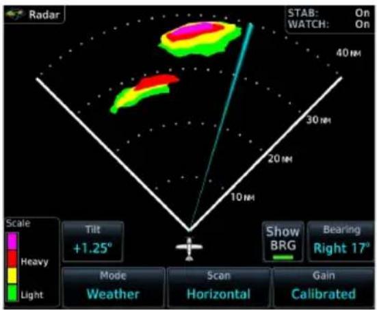
GWX 75 Radar

| WEATHER MODE COLOR | GWX 68/70/75/80 RADAR | THIRD-PARTY RADAR | |
| APPROXIMATE INTENSITY | APPROXIMATE RAINFALL RATE (IN/HR) | RADAR RETURN LEVEL1 | |
| Black < 23 dBZ < .01 0 | |||
| Green 23 dBZ to < 33 dBZ .01 to < 0.1 1 | |||
| Yellow 33 dBZ to < 41 dBZ 0.1 to < 0.5 2 | |||
| Red 41 dBZ to < 49 dBZ 0.5 to < 2.0 3 | |||
| Magenta 49 dBZ and greater 2.0 and greater 4 | |||
| White Turbulence Detection 2 | |||
^1 Consult third-party radar documentation. ^2 GWX 70, GWX 75, and GWX 80 only.
Radar Controls

flowchart
graph TD
    A["Weather Radar Page"] --> B["Show Bearing/Tilt 1"]
    A --> C["Bearing"]
    C --> D["Set bearing"]
    A --> E["Tilt"]
    E --> F["Set tilt"]
    A --> G["Mode"]
    G --> H["Standby"]
    G --> I["Weather"]
    G --> J["Ground"]
    G --> K["Test"]
    A --> L["Scan"]
    L --> M["Horizontal"]
    L --> N["Vertical 2"]
    A --> O["Gain"]
    O --> P["Set to Calibrated"]
Some radars allow independent sweeps when connected to multiple displays.
GWX 68 synchronizes the controls from all connected displays. All other GWX radars receive commands from each display independently and perform a separate sweep for each.
^1 Dependent upon scan type selection. ^2 Not available for RS 181 and RS 811 radars.
SHOW BEARING/TILT
Display the tilt or bearing line depending on the current scan selection. This feature is useful when making horizontal or vertical scan adjustments.
Horizontal Scan Active Vertical Scan Active
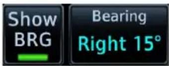

BEARING
FEATURE LIMITATIONS
• Bearing angle not available on RS 181A and RS 811A radars

Directional keys allow fine adjustment of the bearing line angle. This method is optional to tapping and dragging.
TILT
Use antenna tilt to locate the top and bottom of storm cells and to increase intensity of ground target returns. One degree of tilt equals 100 feet of altitude per nautical mile.
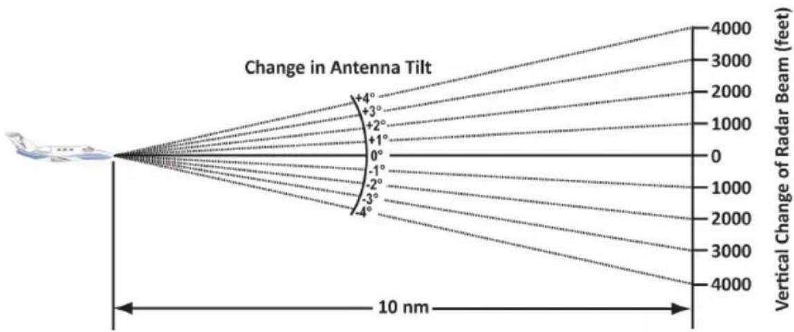
line
| Angle (°) | Vertical Change of Radar Beam (feet) | | --------- | ------------------------------------ | | +4 | 4000 | | +3 | 3000 | | +2 | 2000 | | +1 | 1000 | | 0 | 0 | | -1 | 1000 | | -2 | 2000 | | -3 | 3000 | | -4 | 4000 |Basic Antenna Tilt Setup
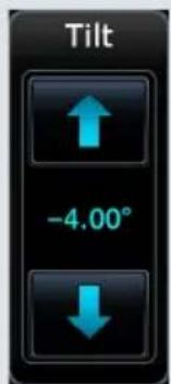
In a typical tilt setup, the bottom of the radar beam is adjusted to 4^ below parallel with the ground. To achieve this:
- Fly the aircraft level.
- Adjust antenna tilt so ground returns display at a distance equal to the aircraft's current altitude (AGL) divided by 1,000.
Remember the following points when flying with the antenna at this basic angle setting.
Altitudes between 2,000 and 30,000 ft AGL:
- Avoid target returns at 5 nm. These may be either weather or ground returns that are 2,000 ft or less below the aircraft.
- Raise the antenna tilt 4^ to separate ground returns from weather returns in flat terrain. Return the antenna to the previous setting after a few sweeps of the radar.
- Set the display range to 60 nm for aircraft flying at 15,000 ft or lower. Monitor ground returns for possible threats.
Altitudes above 29,000 ft:
Be cautious of targets 30 nm or closer. This may indicate a thunderstorm that the aircraft cannot fly over safely.
For a more accurate view of target coverage and intensity, center the tilt angle on the strongest return area, aiming below the freezing level of the storm. In areas of multiple heavy cells, use the vertical scan feature along with antenna tilt to examine the cells. Avoid shadowed areas behind targets.
VERTICAL SCAN
FEATURE LIMITATIONS
• Vertical scan not available on RS 181A and RS 811A radars

Vertical scans focus the radar on a particular vertical target.
- Enable tilt line visibility: Tap Show Tilt.
- Adjust tilt of vertical scan: Tap and drag tilt line up or down. Or tap Tilt and adjust angle using the directional keys.
- Adjust horizontal angle for the vertical scan: Tap Bearing and adjust angle using the directional keys.
Vertical Scan with Stabilization
When vertically scanning with stabilization on, the physical area that the radar is sweeping may not match the displayed vertical scan. This occurs when the aircraft pitch is not at 0^ . To compensate, the GDU does not draw the unscanned portion.
To avoid constant adjustment of the bearing line, ensure that the aircraft wings are level when performing a vertical scan of a storm cell.
HORIZONTAL SCAN
Horizontal scans provide a visual depiction of weather in front of the aircraft.
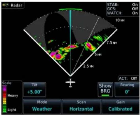
- Enable bearing line visibility: Tap Show BRG.
- Adjust the horizontal scan bearing: Tap and drag bearing line left or right. Or tap Bearing and adjust angle using the directional keys.
- Adjust vertical angle for the horizontal scan: Tap Tilt and adjust angle using the directional keys.
GAIN

NOTE
Precipitation intensity may not be accurate if the gain is changed.
FEATURE LIMITATIONS
• For third-party radars, this control is active only during ground mode
This feature controls the sensitivity of the radar receiver. Adjustments to receiver sensitivity automatically change the intensity of radar targets.
Directional keys allow sensitivity adjustments.

Tapping Set to Calibrated restores the calibrated gain setting and returns intensity depictions to their actual colors.
Radar Alerts

Caution messages alert you when there is a weather radar failure. For a list of possible radar alerts, refer to the annunciations table in this segment.

Radar Alert Annunciation
When a radar alert occurs:
• A textual annunciation appears over the radar sweep
- Scan depictions do not display
- Weather radar overlay detail is absent from Map if heading input is lost
ALERT ANNUNCIATIONS
| ANNUNCIATION ALERT TYPE | CONDITION | |
| Radar Fault | Alert Type: CautionCondition:Data contains a fault unrelated to attitude. |
| Radar Fail | Alert Type: CautionCondition:Weather radar product status is timed out. |
| Radar Controls Disagree | Alert Type: Caution (Third-party radars only)Condition:Radar's actual state does not match the commanded state. |
| Radar Active | Alert Type: CautionCondition:Radar is in standby, but remains active due to another interfacing controller. |
| Off | Alert Type: Advisory (GWX only)Condition:Radar is off. |
| Warm Up XX | Alert Type: Advisory (GWX 68 only)Condition:Radar is warming up. Countdown timer displays number of seconds remaining ("XX"). |
| Standby | Alert Type: AdvisoryCondition:Radar is in standby mode. |
Traffic Awareness

WARNING
Do not rely solely upon the display of traffic information for collision avoidance maneuvering. The traffic display does not provide collision avoidance resolution advisories and does not under any circumstances or conditions relieve the pilot's responsibility to see and avoid other aircraft.
FEATURE LIMITATIONS
- Traffic symbols vary according to traffic source (e.g., TIS-A, TAS, ADS-B)
- Intruding aircraft without altitude reporting capabilities do not display altitude separation data or climb /descent indications
• Available display ranges and vector types are dependent upon traffic source
Available Traffic Sources
• TIS-A
- TCAD 9900B
- TCAD 9900BX
• Ryan TCAD 9900BX w/GDL 88
• TAS/TCAS I
• TCAS II
- ADS-B
Available functions, alerting features, and options are dependent upon on the traffic system source.
ADS-B controls are accessible from the Traffic setup menu. Controls for other traffic systems reside in a control menu and/or on the Traffic page.
Traffic Display

Collision avoidance and traffic surveillance data display on the dedicated Traffic page and as overlays on Map.
The Traffic page displays intruding traffic in relation to the current position and altitude of the aircraft without clutter from other data.

WARNING
Do not rely solely upon the display of traffic information to accurately depict all of the traffic within range of the aircraft. Due to lack of equipment, poor signal reception, and/or inaccurate information from aircraft or ground stations, traffic may be present that is not represented on the display.

radar
| Angle | Value | |-------|-------| | 0° | +12 | | 30° | +12 | | 60° | +12 | | 90° | +12 | | 120° | +12 |Traffic Display Features
| 1 | Ownship IconDepicts current aircraft position.Nose of the ownership is the actual ownership locationUnlike the configured ownership icon on map displays, this icon is always a directional arrow |
| 2 | Ground Station Transmitter Status Icon |
| 3 | Traffic Status & Active ApplicationsStatus indications:On means the AIRB and ATAS traffic applications are activeOff means that air and ground applications are inactiveTest means the traffic test function is activeFail means that ADS-B reports a failure+SURF means that ground targets displays in addition to airborne targetsAltitude filter setting (NORM, ABV, BLW, UNR) |
| 4 | Range RingOuter ring represents selected rangeRange options vary according to traffic application |
| 5 | Selected Vector Type and DurationTypes: Absolute and RelativeRefer to Motion Vectors for more information. |
| 6 | Intruding Aircraft SymbolActual intruder location varies according to symbol type.Tip of directional symbolsCenter of non-directional symbols |
| 7 | Altitude Separation ValueIndicates when an intruder is above or below the ownership.Value appears above or below the traffic symbol, depending on relative altitudePlus or minus sign denotes higher or lower altitude in hundreds of feet |
| 8 | Vertical Trend ArrowActive when an intruder is climbing or descending at a vertical speed greater than 500 fpm. |
| 9 | Next KeyAvailable when multiple targets are spaced closely together. |
| 10 | Selected Traffic Information WindowSelect and view aircraft information for multiple traffic symbols.Refer to Traffic Interactions for more information. |
| 11 | Page Orientation LabelTrack Up orients page to current aircraft GPS trackHeading Up orients page to current aircraft heading (requires heading data source interface) |
GROUND STATION TRANSMITTER STATUS ICON

TIS-B ground station transmitter is providing a traffic picture specific to the ownership aircraft.

Traffic picture may be incomplete in the vicinity of the ownership. A partial traffic picture may be available due to:
- aircraft-to-aircraft ADS-B and/or
- traffic pictures from the ground station customized for other nearby aircraft
TRAFFIC UNITS
| PARAMETER UNITS | |
| Altitude ft | |
| Distance nm | |
Traffic units are always uniform.
Selections in the System Units app do not affect the traffic display.
TRAFFIC GROUPS
When the Traffic Grouping function is active, traffic within close proximity of each other may display as a group.

• Asterisk indicates that the target belongs to a group
• Relative proximity of the closest target determines color
• Depiction is of the most immediate threat
OFF SCALE TRAFFIC ALERTS

Off scale (out of range) traffic alerts are depicted as half yellow symbols on the outermost range ring at the correct bearing.
TRAFFIC OVERLAY STATUS ICON (MAP ONLY)

This icon appears on Map when the traffic overlay is active. It is absent when the overlay function is off. An "X" appears over the icon when the overlay is on but unavailable.

Traffic Setup
Tap Menu to access pilot selectable settings and the self-test functions.
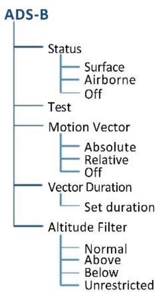
flowchart
graph TD
    A["ADS-B"] --> B["Status"]
    B --> C["Surface"]
    B --> D["Airborne"]
    B --> E["Off"]
    A --> F["Test"]
    F --> G["Motion Vector"]
    G --> H["Absolute"]
    G --> I["Relative"]
    G --> J["Off"]
    A --> K["Vector Duration"]
    K --> L["Set duration"]
    A --> M["Altitude Filter"]
    M --> N["Normal"]
    M --> O["Above"]
    M --> P["Below"]
    M --> Q["Unrestricted"]
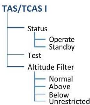
flowchart
graph TD
    A["TAS/TCAS I"] --> B["Status"]
    A --> C["Test"]
    A --> D["Altitude Filter"]
    B --> E["Operate Standby"]
    C --> F["Normal Above"]
    C --> G["Below Unrestricted"]

flowchart
graph TD
    A["TCAS II"] --> B["Standby"]
    A --> C["On"]
    A --> D["Altitude Reporting"]
    A --> E["TA Only"]
    A --> F["TA/RA"]

flowchart
graph TD
    A["TIS-A"] --> B["Status"]
    B --> C["Operate"]
    B --> D["Standby"]
Map Traffic Overlay
The overlay control resides in the Map setup menu.
Home > Map > Menu, and select Traffic.
Traffic Test
FEATURE LIMITATIONS
• ADS-B, TAS, and TCAS applications only
• Available only when the aircraft is on ground (i.e., standby mode)
• Test pattern depiction is dependent upon the active traffic system

The test function displays a test pattern on the Traffic page. For ADS-B, this option is accessible via the Traffic menu.
Altitude Filtering
FEATURE LIMITATIONS
• ADS-B, TAS, and TCAS applications only
Pilot selectable filters limit the display of traffic to a specific altitude range relative to the altitude of the ownership.
Filter selections apply to both the Traffic page and the traffic overlay on Map.
SELECTION LABEL ALTITUDE RANGE
| Normal NORM -2,700 ft to 2,700 ft |
| Above ABV -2,700 ft to 9,900 ft |
| Below BLW -9,900 ft to 2,700 ft |
| Unrestricted UNR -9,900 ft to 9,900 ft |
Traffic Interactions
Selected Traffic Information
- Registration/call sign
- Vehicle type
- Closure rate
- Track
- Ground speed
Selecting a traffic symbol displays information about the aircraft in the upper right corner of the page.
Selections remain active through altitude filtering, zoom scale, and page changes.

Tapping Next repeatedly steps through multiple symbols spaced closely together.

Mute Alert
FEATURE LIMITATIONS
• Available only with GTX 345 and ADS-B software v3.20 or later

When a traffic alert occurs, the Mute Alert option temporarily replaces the Next key.
Traffic Types
TIS-A

NOTE
Garmin is not responsible for Mode S geographical coverage. Operation of the ground stations is the responsibility of the FAA. Refer to the AIM for a terminal Mode S radar site map covering the U.S.
FEATURE REQUIREMENTS
- Aircraft location is within the service volume of a Mode S terminal radar site
• TIS-capable Mode S transponder is interfaced to the GTN
FEATURE LIMITATIONS
- Except for GDL 88 or GTX 345 equipped aircraft, TIS and TAS may not both be displayed at the same time
TIS is available only when the aircraft is within the service volume of a TIS-capable terminal radar site. Aircraft without an operating transponder are invisible to both Traffic Advisory System (TAS) and TIS. Aircraft without altitude reporting capability are shown without altitude separation data or climb/descent indication.
TIS will be unavailable at low altitudes in many areas of the U.S., particularly in mountainous regions. Also, when flying near the “floor” of radar coverage in a particular area, intruders below the client aircraft may not be detected by TIS.
For information about TIS-A functions and limitations, consult the Aeronautical Information Manual (AIM).
TIS-A Features
- 2D graphical depiction of proximate traffic based on data received from terminal radars
- Track vector depicts intruder trajectory over the ground
• Vertical coverage: +3,500/-3,000 ft from ownership
• Eight intruder maximum within an 8 nm radius
• Five second update cycle
• Normal and standby mode options
TIS-A SETUP SELECTIONS
Select an operating mode: Tap Status and choose Operate or Standby.
TIS-A TRAFFIC SYMBOLS
Traffic information is for advisory use only. The pilot is responsible for identifying and avoiding traffic.

Non-threat Traffic

Traffic Advisory (TA)

TA Off-scale
TIS-A STATUS INDICATIONS
| ANNUNCIATION DESCRIPTION | |
| Data Failed | GTN receives data from the transponder, but a failure exists in the data stream. |
| Failed Transponder failure. | |
| No Data GTN is not receiving valid data from the transponder. | |
| TA X.X NM ±XX ↑ | System cannot determine TA bearing. Intruder depiction not available. Annunciation includes:Distance in nautical milesAltitude separation in hundreds of feetAltitude trend arrow (climbing/descending) |
| TA OFF SCALE TA is | outside the selected display range. |
| Traffic Coast x SEC Intruder depictions are more than 6 seconds old. | |
| Traffic Removed | Intruder depictions are more than 12 seconds old. Traffic symbols no longer display. |
| Unavailable | Transponder not receiving TIS-A data from ground station. |
TCAD 9900B
The Traffic and Collision Alert Device (TCAD) 9900B provides a passive system that uses transponder replies from other aircraft to acquire traffic information.

| 1 Altitude Separation 900 ft, Closing | |
| 2 | Traffic Advisory, Altitude Separation 0 ft, Steady Altitude Separation |
| 3 Traffic Advisory, Separation 100 ft, Diverging | |
TCAD 9900B SYMBOLS
| IMMINENT TRAFFIC1 | NON-IMMINENT TRAFFIC | |
 |  | Traffic Closing Vertically |
 |  | Traffic Diverging Vertically |
 |  | Traffic not Closing or Diverging Vertically |
^1 Traffic within ±500 feet and 1.0 nm or no altitude and within 1.0 nm.
TCAD 9900B PAGE SELECTIONS
- Set local barometric pressure: Tap BARO and specify a barometric pressure value.
- Set the active shield: Tap Active Shield and choose En route, Standard, or Terminal.
TCAD 9900B MENU SELECTIONS
Traffic Audio Set volume level of traffic alerts.
Shield Setup Set the active shield. Options are Approach or Standard.
Approach Mode Set the shield height.
Shield Range Set the shield range.
SHIELD SETUP
The Shield Setup function allows you to set the type (mode of operation) and volume of the shield that will provide alerts when entered by other aircraft.
Set an approach shield:
- Select En route, Standard, or Terminal
- Ensure Use DEST APT is deselected and then tap Field Elevation.
- Specify the field elevation value for traffic reporting.
Use DEST APT to automatically use the field elevation of the destination airport of the active flight plan for traffic reporting. If a destination airport is not present in the GTN Xi system, TCAD will not receive a field elevation and therefore not automatically enter approach mode.
Set an En Route, Standard, or Terminal shield:
- Tap Shield Type and select the preferred shield type.
- Tap Shield Height and specify the shield height value.
- Tap Shield Range and specify the shield range value.
Select a mode:
- Approach mode: Toggle the Approach key to choose between Set, Armed, or Active.
• Ground mode: Toggle the Ground key on or off.
TCAD 9900BX
The TCAD 9900BX provides an active system that interrogates other aircraft to acquire traffic information. System setup is identical to TCAD 9900B.
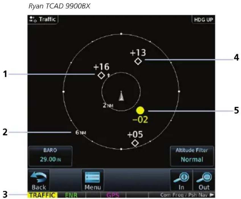
| 1 | Altitude Separation 1,600 ft and Ascending | 4 | Other Traffic, Separation 1,300 ft Above |
| 2 | Range Ring Radius 5 | Traffic Advisory, Altitude Separation 200 ft and Descending | |
| 3 | Traffic Annunciation |
TCAD 9900BX SYMBOLS

Traffic Advisory

Proximity Advisory (color may be configured as cyan)

Other Traffic (color may be configured as cyan)

Out-of-Range Traffic Advisory
Ryan TCAD 9900BX with GDL 88
Ryan TCAD is a system that provides audio and visual alerts for traffic near your aircraft. The information from this system can be interfaced through GTN Xi.
Ryan TCAD Features
• TCAS-like symbols are used in the 9900BX
- Altitude modes are available (normal, look up, look down, unrestricted)
- Ranges are manually controlled for the current shield
TRAFFIC DISPLAY RANGE
Options include: • 1 nm • 2 nm • 2 and 6 nm • 6 and 12 nm • 12 and 24 nm
RYAN TCAD ALERT TYPES
The Ryan TCAD on-board air traffic display identifies potential collision threats. It computes the relative altitude and range of threats from nearby Mode C and Mode S-equipped aircraft. TCAD will not detect aircraft that are not equipped with operating transponders or that are beyond radar coverage. When within the defined limits, TCAD creates a shield of airspace around the aircraft that detected traffic cannot penetrate without triggering an alert.
- TA: Traffic Advisory. Traffic with 500 feet, or less, of altitude separation that is converging or maintaining altitude separation.
- PA: Proximity Advisory. Traffic with 500 feet of altitude separation that is not a TA.
• TRFC: Other traffic.
When TCAD is connected to GTX 345, the available controls will appear as described for TCAS. For details about the Ryan TCAD system, consult the associated pilot's guide.
Ryan TCAD with GDL 88
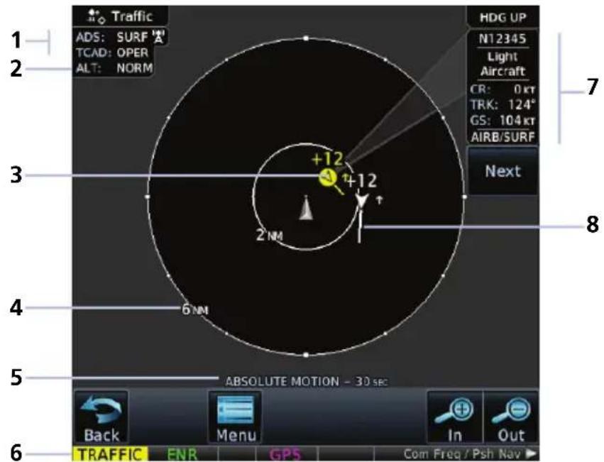
| 1 ADS-B/TCAD Status 5 Selected Vector Type & Duration | ||
| 2 Altitude Filter Setting Indication 6 Traffic Annunciation | ||
| 3 | Alerted Target, 1,200 ft Above and Climbing | 7 Selected Traffic Information |
| 4 Range Ring Radius 8 Traffic Motion Vector | ||
TCAD SETUP SELECTIONS
Tapping TCAD Control provides access to setup controls for the TCAD Traffic display.
Traffic Audio Set volume level of traffic audio.
Field Elevation Set the elevation.
BARO Set the barometric pressure.
Operate Toggle
TCAD traffic on and off.
Ground Mode Toggle TCAD ground mode on and off.
Approach Mode Toggle TCAD approach mode on and off.
TAS/TCAS I
FEATURE LIMITATIONS
Pilots should be aware of TAS limitations. TAS requires transponders of other aircraft to respond to system interrogations. If the transponders do not respond to interrogations due to phenomena such as antenna shading or marginal transponder performance, traffic may be displayed intermittently, or not at all.
Aircraft without altitude reporting capability are shown without altitude separation data or climb descent indication. Pilots should remain vigilant for traffic at all times.
TAS/TCAS I Features
• Airborne traffic system independent of ground radar
• 2D graphical depiction of traffic relative to aircraft position and altitude
TAS/TCAS I SETUP SELECTIONS
| Status | Select operating mode. Options are Operate and Standby. | |
| Test | Initiate a test of the traffic system. | |
| Altitude Filter | Select filter range. Options include: | |
| Normal | Above | |
| Below | Unrestricted | |
TAS/TCAS I TRAFFIC SYMBOLS
Traffic information is for advisory use only. The pilot is responsible for identifying and avoiding traffic conflict.

Other Traffic

Proximity Advisory

Traffic Advisory

TA Off-scale
TAS/TCAS I STATUS INDICATIONS
| ANNUNCIATION DESCRIPTION | |
| Data Failed | GTN receives traffic data, but the TAS unit is reporting a failure. |
| Failed Traffic data failure. | |
| No Data GTN is not receiving valid data from the TAS unit. | |
| TA X.X NM ±XX ↑ | System cannot determine TA bearing. Intruder depiction not available. Annunciation includes:Distance in nautical milesAltitude separation in hundreds of feetAltitude trend arrow (climbing/descending) |
TCAS II
FEATURE LIMITATIONS
• GTS 8000 or third-party TCAS II system
If the installed TCAS II traffic system is not a GTS 8000, refer to the applicable documentation for system-specific information.
TCAS II Features
• Monitors nearby airspace for aircraft flying with operating transponders
- Issues TAs to assist in visual identification of traffic
- Issues RAs to provide recommended vertical guidance maneuvers to resolve traffic conflicts
TCAS II STATUS INDICATIONS
| SELECTION | TRAFFIC PAGE ANNUNCIATIONS |
| TCAS II Self-Test Initiated (TEST) | Test |
| Traffic and Resolution Advisory (TA/RA) | TA/RA |
| Traffic Advisory Only | TA Only |
| TCAS II Standby | STBY |
| TCAS II Failed | Fail |
TCAS II ALERTS
When the TCAS II unit issues a TA or RA, "TRAFFIC" flashes for 5 seconds in the annunciator bar. It remains until no TAs or RAs are detected.
- RA "TRAFFIC" annunciations are white text with red backgrounds
• TA “TRAFFIC” annunciations are black text with yellow backgrounds - If a TA and RA occur simultaneously, only the red and white RA "TRAFFIC" annunciation displays
If GTN Xi is not displaying the Traffic page, the system displays a traffic alert pop-up.
- During a TA event, the system issues a single "Traffic, Traffic" voice alert each time the system detects a new TA threat
-
During an RA event, voice alert(s) provide vertical guidance to resolve the traffic conflict
-
The VSI displays a range of vertical speeds to fly to or avoid as applicable
• Additional voice alerts occur if the RA status changes and when the aircraft is clear of the conflict
If the traffic system cannot determine the bearing of a traffic or RA, the alert displays as a traffic alert banner.
Warning Banner
RA X.X ± XX OR
- Displays when the system is unable to determine the bearing of an RA and extreme pilot vigilance is required
- Indicates distance in nm and altitude separation in hundreds of feet
- Indicates altitude trend up
for climbing and down for descending traffic ^1
Caution Banner
TA X.X ± XX OR
- Displays when the system is unable to determine the bearing of a TA and pilot vigilance is required
- Indicates distance in nm and altitude separation in hundreds of feet
- Indicates altitude trend up
for climbing and down for descending traffic ^1
TCAS II TRAFFIC SYMBOLS
Traffic information is for advisory use only. The pilot is responsible for identifying and avoiding traffic conflict. The TCAS II system categorizes detected traffic into four groups of increasing collision threat potential. Lowest threat is OT and the highest is RA.

OT
Other non-threatening traffic.

PA
Traffic is not currently a threat, but is within 6 nm and ± 1,200 feet of the own-aircraft altitude.

TA
Indicates traffic is within 20-48 seconds of a potential collision area.

Off-scale TA
Traffic is beyond the selected map range and the system displays a half-TA symbol at the edge of the map at the approximate relative bearing of the TA traffic. If TA traffic subsequently meets the criteria for an RA, the system issues an RA.

RA
Indicates traffic is within 15-35 seconds of a potential collision area.

Off-scale RA
If RA traffic is beyond the selected map range, the system displays a half-RA symbol at the edge of the map positioned at the approximate relative bearing to the RA traffic.
TCAS II WITH ADS-B

NOTE
Aircraft that are surveilled only by ADS-B In will not trigger a TCAS resolution advisory.
TCAS II interrogates Mode-S transponder data while automatically receiving ADS-B position and velocity information directly from a comparably equipped aircraft target. For preciseness, the system correlates between two data sources and the system displays the traffic information for the source determined to be the most accurate. Traffic that is not correlated (i.e., only detected by one system but not the other) is also displays for the flight crew. This may occur, for example, if another aircraft is beyond the surveillance range of the TCAS II, but it is still receiving position and velocity information from other ADS-B equipped aircraft. The traffic correlation feature improves the accuracy of the traffic displayed, while reducing the occurrence of displaying a single target twice.
ADS-B
FEATURE REQUIREMENTS
• GTN with external ADS-B In product (GDL 88, GTX 345, or GTS)
FEATURE LIMITATIONS
• Available functions and alerting features are dependent upon the ADS-B traffic system source
ADS-B Features
- Runway and taxiway depiction during SURF mode (< 2 nm range scale)
- Selectable traffic icons display intruder and vector information
- Customizable motion vectors (type, duration)
• Airborne and surface mode options - On-scene mode option (rotorcraft only)
ADS-B SETUP SELECTIONS
| ADS-B Status | Enable automatic mode selection. System selects between Surface and Airborne depending on the state of the aircraft.Selecting Off disables the function. | |
| Test | Initiate a test of the traffic system. | |
| Motion Vector | Select motion vector type. Selecting Off removes all motion vectors from the display. | |
| Absolute | Relative | |
| Off | ||
| Vector Duration | Select the amount of time represented by the endpoint. Options range from 0 seconds to 5 minutes.A longer duration results in a longer vector. | |
| Altitude Filter | Select filter range. Options include: | |
| Normal | Above | |
| Below | Unrestricted | |
ADS-B TRAFFIC SYMBOLS
Traffic Information is for advisory use only. The pilot is responsible for identifying and avoiding traffic conflict.
 | Basic Directional Proximate Di  | nal | |
 | Basic Non-directional Proxima  | n-directional | |
 | Basic Off-scale Selected |  | Proximate Off-scale Selected |
 | Directional (On-Ground) |  | Non-directional Alerted |
 | Non-directional (On-Ground) |  | Off-scale Non-directional Alerted Traffic |
 | Proximate Directional (On-Ground) |  | Directional Alerted Traffic |
 | Proximate Non-directional (On-Ground) |  | Off-scale Directional Alerted Traffic |
 | Directional Surface Vehicle |  | Non-directional Surface Vehicle |
ADS-B TRAFFIC APPLICATIONS
FEATURE REQUIREMENTS
• Aviation database (SURF only)
FEATURE LIMITATIONS
• ATAS does not alert to traffic on ground
ADS-B In traffic supports three applications:
AIRB: Basic Airborne Application
ATAS: ADS-B Traffic Advisory System
SURF: Surface Situation Awareness
AIRB is considered the fundamental airborne traffic application. ATAS provides alerts when airborne traffic trajectories pose a potential collision risk.
SURF provides additional situational awareness when you are on ground or within the terminal environment.
TRAFFIC APPLICATIONS
| AIRB & ATAS | Both active when ADS-B is “On”(airborne traffic indications are available; ATAS arms to provide airborne alerts)Alerts occur when potential collision risks are determined based on current airborne position and trajectory and the position and trajectories of other airborne trafficAirborne traffic alerts only(no alerts on ground or for traffic on the ground)Nominally allow 20 to 40 seconds for flight crew responseProvide aural alerting when traffic alerts occur |
| SURF | Active on ground or within the terminal environment(<5 nm and <1,500 ft above field elevation)Traffic on ground may display when SURF is activeRunway and taxiway depictions when the zoom scale is <2 nm (Traffic page only)Depicts only traffic and ground vehicles equipped with ADS-B Out |
Traffic Application Failures
During normal operation, the “ADS: On” status annunciation means that both AIRB and ATAS applications are active. In the rare event of an application failure, it is possible that only one of the applications may be active. The unit provides indications to reflect which application is no longer operational.
• ADS field indicates "On"
- If AIRB is active and ATAS is failed, the unit displays the system message: "ADS-B traffic alerting function inoperative"
- If AIRB is failed and ATAS is active (and still capable of providing a no-bearing aural alert), "Unavailable" annunciates across the traffic display
MOTION VECTORS
FEATURE LIMITATIONS
• Motion vectors display on the Traffic page only
A motion vector is a line extending from the nose of an intruder icon. Its orientation represents the intruder's direction and movement. A yellow vector indicates when traffic meets intruding TA criteria (i.e., closing rate, distance, vertical separation).
| MOTION VECTOR TYPES | |
| Absolute | Cyan or white vector depending on configurationDepicts intruder ground trackCalculations based on intruder direction and ground speedEndpoint depicts intruder's position over the ground at the end of the selected durationAirborne and ground functionality |
| Relative | Green vectorDepicts intruder movement relative to the ownershipCalculations based on track and ground speed of both intruder and ownershipEndpoint depicts intruder's location relative to the ownership at the end of the selected durationAirborne functionality only“Relative Motion - Unavailable” annunciates during ground operations |
ADS-B STATUS INDICATIONS
| ANNUNCIATION DESCRIPTION | |
| Absolute Motion - XX SEC/MIN | Active motion vector type is absolute. |
| Failed ADS data failure. | |
| No Data GTN is not receiving valid traffic data. | |
| No GPS Position ADS-B LRU detects that GPS unit is initializing. | |
| Relative Motion - XX SEC/MIN | Active motion vector type is relative. |
| Relative Motion - UNAVAILABLE | Aircraft is not airborne and the active motion vector type is relative. |
| Unavailable Necessary traffic data | not available. |
ADS-B TRAFFIC INTERACTIONS
Selected Traffic Information
- Registration/call sign
- Vehicle type
- Closure rate
- Track
- Ground speed
• AIRB/SURF eligibility
Selecting a traffic symbol displays information about the aircraft in the upper right corner of the page.
Selections remain active through altitude filtering, zoom scale, and page changes.
Tapping Next repeatedly steps through multiple symbols spaced closely together.

radar
| Position | Value | |--------|-------| | Top Left | +12 | | Top Right | +50 | | Bottom Left | -12 | | Bottom Right | +50 || 1 | ADS-B/TCAS Status & AIRB/SURF Eligibility Indications | 4 Selected Vector Type & Duration |
| 2 | Altitude Filter Setting Indication 5 Selected Traffic | |
| 3 | Traffic Motion Vector 6 Selected Traffic Information | |
Traffic Alerting
Traffic Alert Types
- Textual annunciations at the bottom of the screen
• Color-coded target icons on Traffic page - Pop-up window when another page is active
Traffic alerts occur anytime there is an increase in the number of traffic advisories. They remain active until the area is clear of all TAs.

GTN 750Xi Series

Traffic pop-ups do not display when the aircraft is on ground.
GTN 650Xi Series

Traffic Alert Pop-up
| ANNUNCIATION | ALERT TYPE | POP-UP | CONDITION | VOICE MESSAGE |
| TRAFFIC | Alert Type: CautionPop-up Alert: YesCondition:• Traffic reports a traffic advisoryVoice Message:• Message content depends on current traffic system configuration |
For installations with GTX 345 and ADS-B software v3.20 or later, tapping the Mute Alert key silences the active traffic alert voice message. This function is applicable only to the active aural alert (does not mute future alerts). For more information, read Aural Alerts in section 2.
Alerting Parameters
Alerting Parameter Considerations
• Altitude separation and trend
- Angle
- Speed
• Closure rate of each aircraft (ownership and target)
Traffic alerting parameters consider several factors in order to allow you enough time to acquire the target and maneuver the aircraft away from conflicting traffic.
To minimize nuisance alerts, traffic alerting sensitivity is adaptive, based on altitude above ground level. No aural alerts are given below 500 ft.
Terrain Awareness

WARNING
Do not use Terrain and obstacle data to navigate or maneuver around terrain. They are an aid to situational awareness only.
FEATURE REQUIREMENTS
All terrain functions require the following components to operate properly.
- Valid 3D GPS position for terrain and obstacle data display
- Valid terrain/obstacle database
FEATURE LIMITATIONS
- Alerting functions are dependent upon the configured terrain alerting options
Terrain Configurations
Available Terrain Modes
• (H)Terrain Proximity
- Terrain Alerting
- TAWS-B ^1
- TAWS-A ^1
• (H)Terrain Alerting
HTAWS ^+
Terrain Proximity displays relative elevations on moving map depictions (Terrain page, Map). It does not provide visual alerts.
Terrain Alerting adds Forward Looking Terrain Alert (FLTA) and Premature Descent Alert (PDA) functions. These include visual alerts when the aircraft flies below an alerting threshold.
^1 Optional.
Terrain controls are accessible from the Terrain menu. Map overlay keys are accessible from the associated map menu.
GPS Altitude for Terrain
FEATURE REQUIREMENTS
GPS altitude is derived from satellite measurements. To acquire an accurate 3D fix (latitude, longitude, altitude), a minimum of four operating satellites must be in view of the GPS receiver antenna.
The terrain system uses GPS altitude and position data to:
- Create a 2D image of surrounding terrain and obstacles relative to the aircraft's position and altitude
- Calculate the aircraft's flight path in relation to surrounding terrain and obstacles
• Predict hazardous terrain conditions and issue alerts
GSL ALTITUDE & INDICATED ALTITUDE
The unit converts GPS altitude data to GSL altitude (i.e., the geometric altitude relative to MSL) for use in terrain functions. All Terrain page depictions and elevation indications are in GSL.
Variations between GSL altitude and the aircraft's corrected barometric altitude (or indicated altitude) are common. As a result, Terrain page altitude data may differ from current altimeter readings. Both GSL altitude and indicated altitude represent height above MSL, but differ in accuracy and reliability.
GSL Altitude Indicated Altitude
• Highly accurate and reliable geometric altitude source
- Does not require local altimeter settings to determine height above MSL
• Not subject to pressure and temperature variations
- Affected primarily by satellite geometry
• Barometric altitude source corrected for pressure variations
- Requires frequent altimeter setting adjustment to determine height above MSL
- Subject to local atmospheric conditions
- Affected by variations in pressure, temperature, and lapse rate
Database Limitations

NOTE
Garmin cross-validates terrain and obstacle data in accordance with TSO-C151d.
However, the information should never be considered all-inclusive. Database inaccuracies or omissions may exist.
Terrain and obstacle data are not available when the aircraft is operating outside of the installed database coverage area.
Garmin obtains terrain and obstacle data from government sources and cannot independently verify the accuracy and completeness of the information. Pilots must familiarize themselves with the appropriate charts and other data for safe flight.
| DATABASE LIMITATION | |
| Terrain | Not available north of 89° N latitude and south of 89° S latitude |
| Obstacle | Coverage areas vary according to database typePower line indications for the contiguous United States and small parts of Canada and MexicoRegional definitions may change without noticeMay not contain uncharted obstaclesMay include power lines or only HOT lines depending on database type1 |
^1 HOT lines are power lines that share location with other obstacles identified by the FAA.
Terrain Display

Terrain, obstacle, and wire data display as overlays on the dedicated Terrain page and as overlays on Map.

Terrain Display Features
| 1 | Ownship IconDepicts current aircraft position. |
| 2 | GSL AltitudeDisplays current GPS height above mean sea level. |
| 3 | North IndicatorIndicates True north. |
| 4 | Page Orientation LabelTrack Up orients page to current aircraft GPS trackHeading Up orients page to current aircraft heading (requires heading data source interface)Heading Up takes priority over Track Up when both orientation inputs are available. |
| 5 | Overlay IconsIndicates power line or obstacle presence at the current zoom scale. |
AUTOMATIC ZOOM

In the event an alert occurs, the page automatically zooms to provide the best depiction of that alerted terrain, obstacle, or power line.
AUTOMATIC DATA REMOVAL

Automatic removal of obstacle and power line data occurs at range scales greater than 10 nm.
Terrain Setup

flowchart
graph TD
    A["Terrain Page Menu"] --> B["View"]
    A --> C["Layers"]
    A --> D["(H)Terrain Alerting"]
    A --> E["(H)TAWS (Optional)"]
    B --> F["360 Arc"]
    C --> G["Flight Plan Legend"]
    D --> H["(H)Terrain Test"]
    D --> I["(H)Terrain Inhibit RP Mode 1"]
    E --> J["TAWS Test"]
    E --> K["TAWS Inhibit Flap Override 2"]
    E --> L["G/S Inhibit GPWS Inhibit it 2"]
Tap Menu to access pilot selectable settings as well as self-test and alert inhibit functions.
Map Terrain Overlays
Overlay controls reside in the Map setup menu.
Home > Map > Menu > Select from Terrain and OBST/Wires.
(H) designates the function is applicable to rotorcraft.
TERRAIN SETUP SELECTIONS
| View | 360 | Changes view format to a 360° ring encircling the aircraft (default view) |
| Arc | Changes view format to a forward-looking 120° arc | |
| Layers | Flight Plan | Toggles the active flight plan overlay on or off (Terrain page only) |
| Legend | Toggles the Terrain and Obstacle/Wire legend on or off | |
| HTAWS & (H)Terrain Alerting | Test [NAME] | Performs a system test of the terrain alerting functionVerifies the validity of required databases |
| [NAME] Inhibit | Inhibits visual alerts for terrain, obstacles, and power linesInhibits the FLTA aural and visual alerts | |
| RP Mode | Reduces alerting thresholds for low-level operations (rotorcraft only) | |
| TAWS-A | Flap Override | Overrides flap-based FIT alerting while other FIT alert functions remain in effectInhibits nuisance FIT alerts where flap extension is not desired |
| G/S Inhibit | Inhibits glideslope or glidepath alerts depending on current stateUse to prevent glideslope/glidepath deviation alerts (e.g., when flying a localizer backcourse approach)Active only for a single approach | |
| GPWS Inhibit | Inhibits GPWS audible and visual alerts (i.e., EDR, ECR, FIT, and NCR) | |
| TAWS A & B | TAWS Test | Performs TAWS alerting system testVerifies the validity of required databases |
| TAWS Inhibit | Inhibits PDA/FLTA audible and visual alertsInhibits EDR/NCR audible and visual alerts for TAWS-B |
Terrain Proximity
FEATURE LIMITATIONS
- Terrain and obstacle depictions are relative to aircraft altitude.
- Obstacle depictions are dependent upon database
• Does not provide visual or aural alerts
View color depictions of terrain and obstacle elevations relative to your current position and altitude.
Terrain Proximity Features
• Non-TSO C151d certified terrain display system
- 2D graphical representation of surrounding terrain, obstacles, and power lines relative to aircraft position and altitude
- Declutter automatically removes obstacle and power line data at large ranges
• Continuous monitoring of database validity, GPS and hardware status
• Displays when higher level terrain functions are active
Terrain Elevation Depictions
Color shading depicts terrain elevations relative to the aircraft's position and altitude. Colors automatically adjust as the aircraft's altitude changes.

Terrain Shading
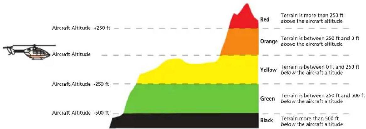
bar_stacked
| Altitude Range | Color | Terrain Range | |---|---|---| | Red | Grey | > 250 ft above | | Orange | Orange | between 250 ft and 0 ft above | | Yellow | Yellow | between 0 ft and 250 ft below | | Green | Green | between 250 ft and 500 ft below | | Black | Black | more than 500 ft below the aircraft altitude |Rotorcraft Terrain Shading
Obstacle Elevation Depictions
FEATURE LIMITATIONS
- Obstacles more than 2,000 ft below current altitude do not display
TOWER OBSTACLES
| UNLIGHTED OBSTACLE | LIGHTED OBSTACLE | OBSTACLE LOCATION | |||
| <1000' AGL | >1000' AGL | <1000' AGL | >1000' AGL | FIXED WING ROTORCRAFT | |
 |  |  |  | Red obstacle is above or within 100 ft below current altitude. | Red obstacle is at or above current altitude. |
 |  |  |  | Yellow obstacle is between 100 ft and 1000 ft below current altitude. | Yellow obstacle is within 250 ft below current altitude. |
 |  |  |  | White obstacle is between 1,000 ft and 2,000 ft below current altitude. | White obstacle more than 250 ft below current altitude. |
WIND TURBINE OBSTACLES
| UNLIGHTED WIND TURBINE OBSTACLE | LIGHTED WIND TURBINE OBSTACLE | OBSTACLE LOCATION | |
| FIXED WING ROTORCRAFT | |||
 |  | Red obstacle is above or within 100 ft below current altitude. | Red obstacle is at or above current altitude. |
 |  | Yellow obstacle is between 100 ft and 1,000 ft below current altitude. | Yellow obstacle is within 250 ft below current altitude. |
 |  | White obstacle is more than 1,000 ft below current altitude. | White obstacle more than 250 ft below current altitude. |
POWER LINE OBSTACLES
| OBSTACLE POWER LINE OBSTACLE LOCATION | |
 | Red power line is above or within 100 ft below current altitude. |
 | Yellow power line is between 100 ft and 1,000 ft below current altitude. |
 | White power line is between 1,000 ft and 2,000 ft below current altitude. |
OBSTACLE GROUPS

An asterisk indicates when the obstacle database contains only a single latitude and longitude for a group of obstacles. This occurrence is rare.
Alert Types
The behavior of an alerting function is determined at installation. Installer configurable settings allow:
- Alert suppression for specific runway types
• Gender selection for voice messages
• Volume level
TERRAIN ALERTING
- Imminent Impact
- Reduced Clearance
- Premature Descent
TAWS-A
- Imminent Impact
- Reduced Clearance
- Premature Descent
• Excessive Descent Rate
• Excessive Closure Rate - Negative Climb Rate
- Flight Into Terrain
• Excessive Below Glideslope/Glidepath Deviation
TAWS-B
- Imminent Impact
- Reduced Clearance
- Premature Descent
• Excessive Descent Rate - Negative Climb Rate
Available alerting functions depend on the installed terrain system.
| ALERT TYPE CONDITION | |
| Imminent Impact1 | Aircraft reaches the minimum clearance altitude of any obstacle (IOI), terrain (ITI), or power line (ILI) in the projected flight path. |
| Reduced Clearance1 | Aircraft's vertical flight path is projected to be within the minimum clearance altitude of an obstacle (ROC), terrain (RTC), or power line (RLC). |
| Premature Descent2 | Aircraft is significantly below the normal approach path for the nearest runway. Altitude is <700 ft above terrain Distance from destination airport is 15 nm or less |
| Excessive Descent Rate | Aircraft descends toward terrain at an excessive rate. |
| Excessive Closure Rate3 | Aircraft closes upon terrain at a rate excessive for gear and flaps in the landing configuration. |
| Negative Climb Rate | Aircraft loses altitude following takeoff. Altitude is <700 ft above terrain Distance from departure airport is 2 nm or less Deviation from departure heading is <110° |
| Flight Into Terrain | Aircraft is too low with respect to terrain. Based on landing gear status, flap position, and ground speed. |
| Excessive Below Glideslope or Glidepath Deviation | Aircraft is significantly below the glidepath for the selected approach. Active only after departure and when the following conditions are met. Altitude is <1,000 ft AGL Gear is configured for landing ILS, LPV, LNAV/VNAV, or LNAV+V approach is active and the unit is indicating vertical navigation |
^1 Alerting inhibited <200 ft AGL within 0.5 nm of approach runway or <125 ft AGL within 1.0 nm of runway threshold.
^2 Alerting inhibited within 0.5 nm of approach runway or <125 ft AGL within 1.0 nm of runway threshold. Alerting thresholds for final descent are based on current position, speed, and flight path data.
^3 Alerting inhibited within 5 nm of nearest airport, except when FLTA is not available. In such cases, "TAWS N/A" or "TAWS FAIL" annunciates and ECR alerting remains active until landing.
Alerting Thresholds
| FLIGHT PHASE | MINIMUM CLEARANCE ALTITUDE | |
| LEVEL FLIGHT DESCENDING | ||
| En Route 700 ft 500 ft | ||
| Terminal 350 ft 300 ft | ||
| Approach 150 ft 100 ft | ||
| Departure 100 ft 100 ft | ||
EDR THRESHOLDS
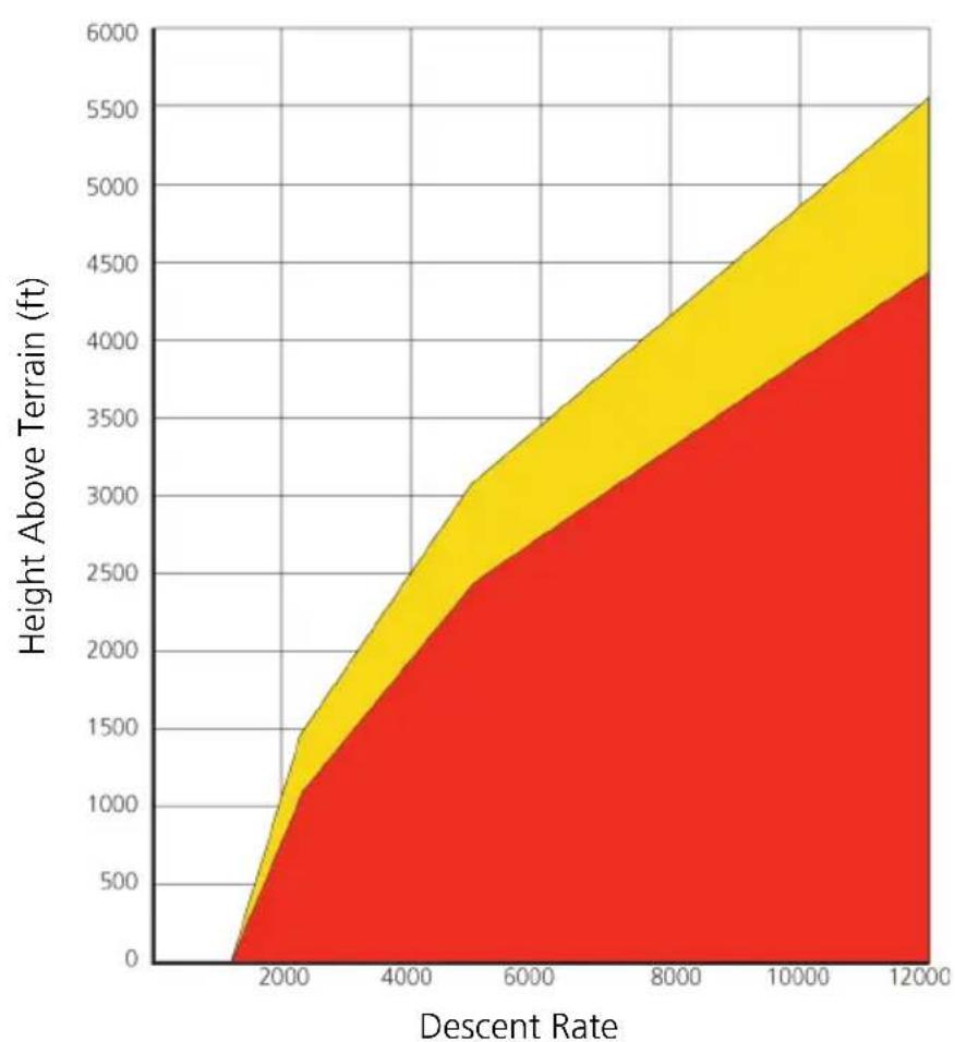
area
| Descent Rate | Height Above Terrain (ft) | | ------------ | ------------------------- | | 0 | 0 | | 2000 | 1000 | | 4000 | 2000 | | 6000 | 2500 | | 8000 | 3000 | | 10000 | 3500 | | 12000 | 4500 |Sink Rate "Pull Up"

PDA THRESHOLD

area
| Distance from Destination Airport (nm) | Height Above Terrain (ft) | | -------------------------------------- | ------------------------- | | 1 | 0 | | 2 | 100 | | 3 | 200 | | 4 | 250 | | 5 | 300 | | 6 | 350 | | 7 | 375 | | 8 | 390 | | 9 | 400 | | 10 | 410 | | 11 | 420 | | 12 | 430 | | 13 | 450 | | 14 | 500 | | 15 | 700 |Alerting Area

NER THRESHOLDS
Alert triggers: altitude loss, sink rate
Height Above Terrain (ft)Height

area
| Altitude Loss (ft) | Value | | ------------------ | ----- | | 0 | 0 | | 20 | 200 | | 40 | 400 | | 60 | 600 | | 80 | 650 | | 100 | 650 | | 120 | 650 | | 140 | 650 |
area
| Sink Rate (fpm) | Value | | --------------- | ----- | | 0 | 0 | | 500 | 700 | | 4000 | 700 |"Don't Sink"

EXCESSIVE CLOSURE RATE ALERT

area_stacked
| Category | CAution (FLTA available, Gear Down) "Pull-up" | Warning (FLTA available, Gear Down) "Pall-up" | Caution (FLTA available, Gear Up) "Terrain-Terrain" | Warning (FLTA available, Gear Up) "Pall-up" | Caution (FLTA not available) "Pull-up" | Caution (FLTA not available) "Terrain-Terrain" | |---|---|---|---|---|---|---| | 2000 | 0 | 0 | 0 | 0 | 0 | 0 | | 2500 | 0 | 0 | 0 | 0 | 0 | 0 | | 3000 | 0 | 0 | 0 | 0 | 0 | 0 | | 3500 | 0 | 0 | 0 | 0 | 0 | 0 | | 4000 | 650 | 1500 | 1250 | 1750 | 1500 | 1750 | | 4500 | 650 | 1550 | 1250 | 1750 | 1550 | 1750 | | 5000 | 650 | 1600 | 1250 | 1750 | 1600 | 1750 | | 5500 | 650 | 1650 | 1250 | 1750 | 1650 | 1750 | | 6000 | 650 | 1750 | 1250 | 1750 | 1750 | 1750 | | 6500 | 650 | 1800 | 1250 | 1750 | 1800 | 1750 | | 7000 | 650 | 1850 | 1250 | 1750 | 1850 | 1750 |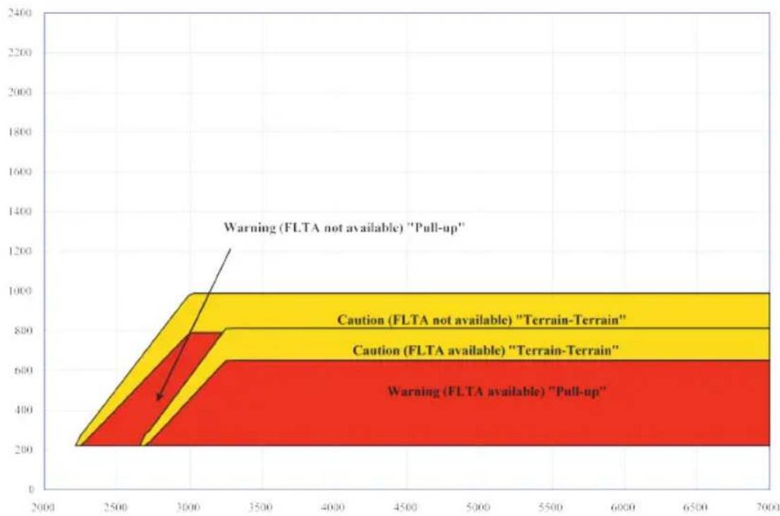
bar_stacked
| Range | Warning (FLTA available) "Pull-up" | Caution (FLTA available) "Terrain-Terrain" | Caution (FLTA not available) "Terrain-Terrain" | | --------- | ----------------------------------- | ------------------------------------------ | ---------------------------------------------- | | 2000-2500 | 200 | 200 | 200 | | 2500-3000 | 600 | 800 | 1000 | | 3000-3500 | 600 | 800 | 1000 | | 3500-4000 | 600 | 800 | 1000 | | 4000-4500 | 600 | 800 | 1000 | | 4500-5000 | 600 | 800 | 1000 | | 5000-5500 | 600 | 800 | 1000 | | 5500-6000 | 600 | 800 | 1000 | | 6000-6500 | 600 | 800 | 1000 | | 6500-7000 | 600 | 800 | 1000 |FLIGHT INTO TERRAIN ALERT

area
| Altitude Change Rate (fpm) | Height Above Terrain (ft) | | :--- | :--- | | -1500 | 500 | | -1000 | 300 | | -500 | 200 | | 0 | 200 | | 500 | 200 | | 1000 | 200 | | 1500 | 200 | The chart displays a single yellow region representing combinations of gear up/down, ground speed, flaps landing speed, and terrain, each associated with a specific coordinate on the x-axis. The labels indicate that “Too Low” or “Gear” or “Down” denote different scenarios or conditions for each scenario. The chart is divided into three horizontal bands: bottom-left (high altitude), middle-right (moderate altitude), and top-left (low altitude). The central label “Gear Up, Groundspeed Below either V_LE or maximum flaps landing speed, whichever is less - 'Too Low - Gear' *” appears in the upper left region, suggesting it may represent a key condition or target. The bottom-left region contains an orange band labeled “Gear Up - 'Too Low - Gear' or Gear Down, Flaps not in Landing Position - 'Too Low - Flaps' *” in the middle right, implying a range of flaps. The bottom-right region contains an orange band labeled “Either Gear Up or Flaps not in Landing Position, Groundspeed Above either V_LE or maximum flaps landing speed, whichever is less - 'Too Low - Terrain'”.* Flap position will not trigger alert if Flap Override option is enabled. To enable, tap Menu > Flap Override.
OVERRIDING FLAPS-BASED FIT ALERTING
The FLAP O/R (Flap Override) should be activated when an approach without flaps is going to be performed.
To reduce nuisance FIT alerts on approaches where flap extension is not desired (or is intentionally delayed), you may override FIT alerting based on the flap position, while all other FIT alerting remains in effect.
FIT alerts also occur during takeoff or go-around if the aircraft's height above ground level (as determined by the radar altimeter) is too close to rising terrain. TAWS-A will issue the aural message "Too Low - Terrain" and visual annunciations when conditions enter the caution alert area.
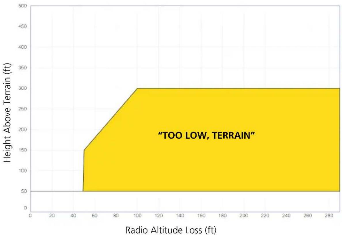
area
| Radio Altitude Loss (ft) | Height Above Terrain (ft) | | ------------------------ | ------------------------- | | 50 | 150 | | 100 | 300 |EXCESSIVE BELOW GLIDESLOPE/GLIDEPATH DEVIATION ALERT
A Glideslope Deviation or Glidepath Deviation (GSD) caution alert is issued when the system detects that the aircraft is significantly below the glidepath for the selected approach.
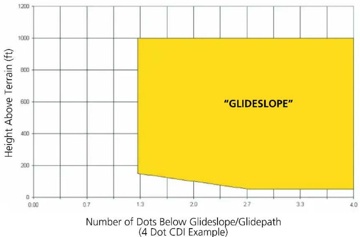
area
| Number of Dots Below Glideslope/Glidepath | Height Above Terrain (ft) | | :--- | :--- | | 1.3 | 150 | | 2.0 | 100 | | 2.7 | 50 | | 3.3 | 50 | | 4.0 | 50 |Terrain Alerting
FEATURE REQUIREMENTS
- Valid terrain/obstacle database
• Valid 3D GPS position solution
Receive visual alerts for potential flight path conflicts involving terrain, obstacles, or power lines. Alerting behavior is determined at installation.
Terrain Alerting Features
• Non-TSO C151d certified terrain alerting system
• FLTA functions: RTC, RLC, ROC, ITI, ILI, and IOI
• Premature Descent alerts
- Terrain depictions and display overlays
- Cautions and warnings indicate alert severity and threat type
- Textual annunciations
- Pop-up alerts
- Threat location indication on Terrain page and Map
• Self-test and alert inhibit functionality
| TERRAIN ALERTING | |
| ANNUNCIATION ALERT TYPE | CONDITION | AURAL MESSAGE | |
| PULL UP | Alert Type:WarningCondition:FLTA Terrain Warning (RTC-W, ITI-W)Aural Messages:“Terrain Ahead, Pull Up; Terrain Ahead, Pull Up”or“Terrain, Terrain; Pull Up, Pull Up” |
| Alert Type:WarningCondition:FLTA Obstacle Warning (ROC-W, IOI-W)Aural Messages:“Obstacle Ahead, Pull Up; Obstacle Ahead, Pull Up”or“Obstacle, Obstacle; Pull Up, Pull Up” | |
| Alert Type:WarningCondition:FLTA Wire Warning (ILI-W, RLC-W)Aural Messages:“Wire Ahead Pull Up, Wire Ahead Pull Up”or“Wire Wire, Pull Up, Pull Up” | |
| TERRAIN | Alert Type:CautionCondition:FLTA Terrain Caution (RTC-C, ITI-C)Aural Messages:“Terrain Ahead; Terrain Ahead”or“Caution, Terrain; Caution, Terrain” |
| OBSTACLE | Alert Type:CautionCondition:FLTA Obstacle Caution (ROC-C, IOI-C)Aural Messages:“Obstacle Ahead; Obstacle Ahead”or“Caution, Obstacle; Caution, Obstacle” |
| WIRE | Alert Type: CautionCondition: FLTA Wire Caution (ILI-C, RLC-C)Aural Messages:“Wire Ahead, Wire Ahead”or“Caution Wire, Caution Wire” |
| TERRAIN | Alert Type: CautionCondition: Premature Descent Alert Caution (PDA)Aural Messages: “Too Low, Terrain” |
| None | Alert Type: InformationalCondition: Voice Call Out (VCO-500)Aural Messages: “Five-Hundred” |
TERRAIN SYSTEM STATUS
During power-up, the terrain system conducts a self-test of its aural and visual annunciations. This test can also be manually initiated. An aural alert is issued at test completion. Terrain system testing is disabled when ground speed exceeds 30 knots.
| ANNUNCIATION ALERT TYPE | CONDITION | AURAL MESSAGE | |
| None | Alert Type: InformationalCondition: Terrain AvailableAural Messages: None |
| TER TEST | Alert Type: InformationalCondition: Terrain System Test in ProgressAural Messages: None |
| None | Alert Type: InformationalCondition: Terrain System Test PassAural Messages: “Terrain System Test OK” |
| TER N/A | Alert Type: CautionCondition: Terrain N/AAural Messages: “Terrain Not Available” |
| TER INHB | Alert Type: InformationalCondition: Terrain Alerting is DisabledAural Messages: None |
| TER FAIL | Alert Type: CautionCondition: Terrain System Test FailAural Messages: “Terrain System Failure” |
Alert Inhibit, TAWS & Terrain Alerting

The Terrain Inhibit control is accessible via the terrain pop-up alert or the Terrain page menu.
Always use discretion when inhibiting TAWS or Terrain Alerting alerts. Re-activate the alert function when appropriate.
| TERRAIN INHIBIT FUNCTIONS | |
| INHIBIT | Manually inhibits TAWS or Terrain Alerting aural and visual alerts for low altitude approaches or rotorcraft operation. |
| AUTOMATIC INHIBIT | Automatically inhibits TAWS and Terrain Alerting alerts when the aircraft meets the following approach criteria.TAWS: • GPS/SBAS approach• Position inside FAFTAWS & TERRAIN• Altitude <200 ft above ALERTING: runway elevation• Position <0.5 nm of approach end or between each runway end |
TAWS-A INHIBIT ANNUNCIATIONS
Terrain Page

TAWS-A alert inhibit annunciations appear at the bottom right of the display.
- "FLAP OVRD" does not annunciate if GPWS Inhibit is already active, as both functions inhibit FIT alerts.
- A plus sign indicates multiple alerts (e.g., "TAWS INHB+")
TAWS-B
FEATURE REQUIREMENTS
- Valid 3D GPS position
• TAWS-B feature enablement
TAWS-B Features
- Optional TSO-C151d Class B terrain alerting system
- All Terrain alerting functions plus: premature descent, excessive descent rate, negative climb rate, and altitude voice callout (500 ft) alerts
TAWS-B Setup Selections
View Selects 360° or Arc view on terrain page.
| Layers | Selects to display flight plan and/or legend on the terrain page. |
| TAWS InhibitPrevents TAWS alerts. | |
| Test | Tests the TAWS system. Available only when the aircraft is on the ground. |
TAWS-B Alerts
| TAWS-B ALERTS | |
| ANNUNCIATION ALERT TYPE | POP-UP | CONDITION | |
| PULL UP | Alert Type:WarningCondition: Excessive Descent Rate Warning (EDR-W)Aural Message: "Pull Up" |
| Alert Type:WarningCondition: FLTA Terrain Warning (RTC-W, ITI-W)Aural Message:"Terrain Ahead, Pull Up; Terrain Ahead, Pull Up"or"Terrain, Terrain; Pull Up, Pull Up" | |
| Alert Type:WarningCondition: FLTA Obstacle Warning (ROC-W, IOI-W)Aural Message:"Obstacle Ahead, Pull Up; Obstacle Ahead, Pull Up"or"Obstacle, Obstacle; Pull Up, Pull Up" | |
| Alert Type:WarningCondition: FLTA Wire Warning (ILI-W, RLC-W)Aural Message:"Wire Ahead Pull Up, Wire Ahead Pull Up"or"Wire, Wire, Pull Up, Pull Up" | |
| TERRAIN | Alert Type:CautionCondition: FLTA Terrain Caution (RTC-C, ITI-C)Aural Message:"Terrain Ahead; Terrain Ahead"or"Caution, Terrain; Caution, Terrain" |
| OBSTACLE | Alert Type: CautionCondition: FLTA Obstacle Caution (ROC-C, IOI-C)Aural Message:“Obstacle Ahead; Obstacle Ahead”or“Caution, Obstacle; Caution, Obstacle” |
| WIRE | Alert Type: CautionCondition: FLTA Wire Caution (ILI-C, RLC-C)Aural Message:“Wire Ahead, Wire Ahead”or“Caution Wire, Caution, Wire” |
| TERRAIN | Alert Type: CautionCondition: Premature Descent Alert Caution (PDA)Aural Message: “Too Low, Terrain” |
| Alert Type: CautionCondition: Excessive Descent Rate Caution (EDR-C)Aural Message: “Sink Rate” | |
| Alert Type: CautionCondition: Negative Climb Rate Caution (NCR-C)Aural Message:“Don’t Sink”or“Too Low, Terrain” | |
| None | Alert Type: InformationalCondition: Voice Call Out (VCO-500)Aural Message: “Five-Hundred” |
Altitude VCO
TAWS-B provides aural advisory alerts as the aircraft descends, beginning at 500 feet above the terrain, as determined by the radar altimeter (if greater than 5 NM from the nearest airport) or 500 feet above the nearest runway threshold elevation (if less than 5 NM from the nearest airport). Upon descent to this altitude, TAWS-B issues the aural alert message “Five-hundred.”
TAWS-B Not Available Alert
TAWS-B requires a 3D GPS position solution along with specific vertical accuracy minimums. Should the position solution become degraded or if the aircraft is out of the database coverage area, the annunciation “TAWS N/A” is generated in the annunciation window and on the TAWS-B page. The aural message “TAWS Not Available” is generated. When the GPS signal is re-established and the aircraft is within the database coverage area, the aural message “TAWS Available” is generated (when the aircraft is airborne).
TAWS-B Failure Alert
TAWS-B continually monitors several system-critical items such as database validity, hardware status, and GPS status. If the terrain/obstacle database is not available, the aural message “TAWS System Failure” is generated along with a “TAWS FAIL” annunciation.
TAWS-B SYSTEM STATUS
During power-up, TAWS-B conducts a self-test of its aural and visual annunciations. The system test can also be manually initiated. An aural alert is issued at test completion. TAWS System Testing is disabled when ground speed exceeds 30 knots.
| ANNUNCIATION ALERT TYPE AURAL MESSAGE | ||
| None TAWS Available “TAWS Available” | ||
| TAWS TEST | TAWS System Test in Progress | None |
| None TAWS System Test Pass “TAWS System Test OK” | ||
| TAWS N/A | TAWS N/A “TAWS Not Available” | |
| TAWS INHB | TAWS Alerting is Disabled None | |
| TAWS FAIL | TAWS System Test Fail “TAWS System Failure” | |
TAWS-A
FEATURE REQUIREMENTS
- Valid terrain/obstacle/navigation database
- Valid 3D GPS position
- Valid flap and landing gear status inputs
- Valid radar altimeter
- Valid air data computer
Class A TAWS incorporates radar altimeter input with the GSL altitude to provide a more accurate position reference when at lower altitudes for certain alert types, and to retain a level of ground proximity warning capability in the unlikely event of a navigation, terrain or obstacle database failure.
TAWS-A Features
- Optional TSO-C151d Class A terrain alerting system
- All Terrain-FLTA functions plus: premature descent, excessive descent and closure rate, negative climb rate, flight into terrain, excessive below glideslope/glidepath deviation
- Visual and aural annunciations when terrain and obstacles are within the given altitude threshold from the aircraft
TAWS-A Setup Selections
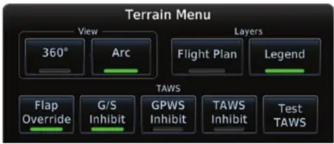
Tap Menu to access setup options. Selections are grouped by function: View, Layers, and TAWS.
INHIBIT
Manually inhibits FLTA or PDA visual alerts for low altitude approaches.
AUTOMATIC INHIBIT
Automatically inhibits FLTA alerts when the aircraft meets the following approach criteria.
• Altitude <200 ft above runway elevation
- Position <0.5 nm off approach end or between each runway end
TAWS-A Alerts
| TAWS-A ALERTS | |
| ANNUNCIATION ALERT TYPE | POP-UP | CONDITION | |
| PULL UP | Alert Type:WarningCondition: Reduced Required Terrain Clearance (RTC)Pop-up Alert:“Terrain - Pull Up”or“Terrain Ahead - Pull Up"Aural Message:“Terrain, Terrain; Pull Up, Pull Up”or“Terrain Ahead, Pull Up; Terrain Ahead, Pull Up” |
| Alert Type:WarningCondition: Imminent Terrain Impact (ITI)Pop-up Alert:“Terrain - Pull Up”or“Terrain Ahead - Pull Up"Aural Message:“Terrain, Terrain; Pull Up, Pull Up”or“Terrain Ahead, Pull Up; Terrain Ahead, Pull Up” | |
| Alert Type:WarningCondition: Reduced Required Obstacle Clearance (ROC)Pop-up Alert:“Obstacle Pull Up”or“Obstacle Ahead - Pull Up"Aural Message:“Obstacle, Obstacle; Pull Up, Pull Up”or“Obstacle Ahead, Pull Up; Obstacle Ahead, Pull Up” | |
| PULL UP | Alert Type:WarningCondition: Imminent Obstacle Impact (IOI)Pop-up Alert:“Obstacle Pull Up”or“Obstacle Ahead - Pull Up"Aural Message:“Obstacle, Obstacle; Pull Up, Pull Up”or“Obstacle Ahead, Pull Up; Obstacle Ahead, Pull Up” |
| Alert Type:WarningCondition: Excessive Descent Rate (EDR)Pop-up Alert: “Pull Up"Aural Message: “Pull Up” | |
| Alert Type:WarningCondition: Excessive Closure Rate (ECR)Pop-up Alert: “Pull Up"Aural Message: “Pull Up” | |
| Alert Type:WarningCondition: Imminent Line Impact (ILI)Pop-up Alert: “Wire Ahead - Pull Up"Aural Message:“Wire Ahead, Pull Up; Wire Ahead, Pull Up”or“Wire, Wire; Pull Up, Pull Up” | |
| Alert Type:WarningCondition: Reduced Line Clearance (RLC)Pop-up Alert: “Wire Ahead - Pull Up"Aural Message:“Wire Ahead, Pull Up; Wire Ahead, Pull Up”or“Wire, Wire; Pull Up, Pull Up” | |
| TERRAIN | Alert Type: CautionCondition: Reduced Required Terrain Clearance (RTC)Pop-up Alert:“Caution - Terrain”or“Terrain Ahead”Aural Message:“Caution, Terrain; Caution, Terrain”or“Terrain Ahead; Terrain Ahead” |
| Alert Type: CautionCondition: Imminent Terrain Impact (ITI)Pop-up Alert:“Caution - Terrain”or“Terrain Ahead”Aural Message:“Caution, Terrain; Caution, Terrain”or“Terrain Ahead; Terrain Ahead” | |
| OBSTACLE | Alert Type: CautionCondition: Reduced Required Obstacle Clearance (ROC)Pop-up Alert:“Caution - Obstacle”or“Obstacle Ahead”Aural Message:“Caution, Obstacle; Caution, Obstacle”or“Obstacle Ahead; Obstacle Ahead” |
| Alert Type: CautionCondition: Imminent Obstacle Impact (IOI)Pop-up Alert:“Caution - Obstacle”or“Obstacle Ahead”Aural Message:“Obstacle Ahead; Obstacle Ahead”or“Caution, Obstacle; Caution, Obstacle” | |
| WIRE | Alert Type: CautionCondition: Imminent Line Impact (ILI)Pop-up Alert: “Wire Ahead”Aural Message:“Wire Ahead; Wire Ahead”or“Caution, Wire; Caution, Wire” |
| WIRE | Alert Type: CautionCondition: Reduced Line Clearance (RLC)Pop-up Alert: “Wire Ahead”Aural Message:“Wire Ahead; Wire Ahead”or“Caution, Wire; Caution, Wire” |
| TERRAIN | Alert Type: CautionCondition: Premature Descent Alert (PDA)Pop-up Alert: “Don’t Sink”Aural Message: “Too Low, Terrain” |
| Alert Type: CautionCondition: Excessive Descent Rate (EDR)Pop-up Alert: “Sink Rate”Aural Message: “Sink Rate” | |
| Alert Type: CautionCondition: Excessive Closure Rate (ECR)Pop-up Alert: “Terrain”Aural Message: “Terrain, Terrain” | |
| Alert Type: CautionCondition: Negative Climb Rate (NCR)Pop-up Alert:“Don’t Sink”or“Too Low - Terrain”Aural Message:“Don’t Sink”or“Too Low, Terrain” | |
| TERRAIN | Alert Type:CautionCondition: Flight Into Terrain High Speed (FIT)Pop-up Alert: "Too Low, Terrain"Aural Message: "Too Low, Terrain" |
| Alert Type:CautionCondition: Flight Into Terrain Gear (FIT)Pop-up Alert: "Too Low, Gear"Aural Message: "Too Low, Gear" | |
| Alert Type:CautionCondition: Flight Into Terrain Flaps (FIT)Pop-up Alert: "Too Low, Flaps"Aural Message: "Too Low, Flaps"Alert Type:CautionCondition: Flight Into Terrain Takeoff (FIT)Pop-up Alert: "Too Low, Terrain"Aural Message: "Too Low, Terrain" | |
| GLIDESLOPE | Alert Type:CautionCondition: Glideslope Deviation (GSD)Pop-up Alert: "Glideslope"Aural Message: "Glideslope" |
| None | Alert Type: InformationalCondition: Altitude Voice Call Out (VCO)Pop-up Alert: NoneAural Message: "Five-Hundred" |
| Alert Type: InformationalCondition: TAWS AvailablePop-up Alert: N/AAural Message: "TAWS Available" | |
| TAWS TEST | Alert Type: InformationalCondition: TAWS system test in progress.Pop-up Alert: N/AAural Message: None |
| None | Alert Type: InformationalCondition: TAWS System Test PassPop-up Alert: N/AAural Message: “TAWS System Test OK” |
| TAWS N/A | Alert Type: CautionCondition: TAWS N/APop-up Alert: N/AAural Message: “TAWS Not Available” |
| TAWS INHB | Alert Type: InformationalCondition: TAWS Alerting is disabled.Pop-up Alert: N/AAural Message: None |
| TAWS FAIL | Alert Type: CautionCondition: TAWS system test has failed.Pop-up Alert: N/AAural Message: “TAWS System Failure” |
| Alert Type: Caution1Condition:Incorrect TAWS configurationInvalid/missing terrain, airport, or obstacle databaseTAWS audio faultPop-up Alert: N/AAural Message: “TAWS System Failure” | |
| TAWS N/A | Alert Type: CautionCondition: No GPS positionPop-up Alert: N/AAural Message: “TAWS Not Available” |
| Alert Type: CautionCondition: GPS position unavailable/degraded. Outside of terrain database coverage.Pop-up Alert: N/AAural Message: “TAWS Not Available” | |
| None | Alert Type: InformationalCondition: Sufficient GPS signal reception restored.Pop-up Alert: N/AAural Message: “TAWS Available” (aural message only in flight) |
| GPWS FAIL | Alert Type: CautionCondition:Incorrect TAWS configurationRadar altimeter unavailableGPS position unavailable/degradedTAWS audio faultPop-up Alert: N/AAural Message: “GPWS System Failure” |
| GPWS INHB | Alert Type: InformationalCondition: GPWS InhibitPop-up Alert: NoneAural Message: “GPWS System Failure” |
| GPWS N/A | Alert Type: CautionCondition:GPWS Not AvailableIncorrect TAWS configurationRadar altimeter unavailableGPS position unavailable/degradedTAWS audio faultPop-up Alert: N/AAural Message: “GPWS System Failure” |
| G/S INHB | Alert Type: InformationalCondition: Glideslope InhibitPop-up Alert: N/AAural Message: None |
| FLAP OVRD | Alert Type: InformationalCondition: FLAP OverridePop-up Alert: N/AAural Message: None |
^1 VCO alerts are not issued if both TAWS and GPWS systems have failed or are not available.
GSD alert is available if a valid ILS is being used for navigation, even when no valid GPS signal is being received.
ENABLE FLAP OVERRIDE
When the Flaps Override option is enabled, the annunciation "FLAP OVRD" is annunciated on the TAWS-A Page. If GPWS alerts are also inhibited (which include FIT), the "FLAP OVRD" annunciation is not shown.
-
Tap Menu.
-
Tap Flap Override to toggle the override state.
GSD alerting is only active after departure and the following conditions are met:
- An ILS, LPV, LNAV/VNAV, or LNAV+V approach is active and vertical navigation indications are being displayed.
• Aircraft is below 1000 feet AGL.
• Gear is configured for landing.
When a GSD caution alert occurs, the aural and visual annunciation "GLIDESLOPE" is issued. If a GSD caution alert occurs on an LPV, LNAV/VNAV, or LNAV+V approach, the aural and visual annunciation "GLIDESLOPE" is issued.
INHIBITING GLIDESLOPE DEVIATION (GSD) ALERTS
When G/S alerts are inhibited, they are only inhibited for a single approach. To inhibit G/S alerts on the next approach, the G/S Inhibit function must be activated again between the first and second approaches.
- Tap Menu.
- Tap G/S Inhibit to inhibit or enable glideslope or glidepath alerts.
The Glideslope (G/S) Inhibit function:
- Should be activated when flying a localizer backcourse approach to prevents nuisance GSD alerts
- GSD alerts are inhibited independent from all other FLTA, PDA, and GPWS alerts
- Will only be active for a single approach and will not remain active for subsequent approaches
INHIBITING GPWS ALERTS (EDR, ECR, FIT, AND NCR)
The “Inhibit GPWS” function only affects GPWS alerts (EDR, ECR, NCR, and FIT). Alerting for FLTA, PDA, and GSD is controlled independently from the GPWS alerts listed below.
EDR, ECR, FIT, and NCR aural and visual alerts can be manually inhibited as a group. Discretion should be used when inhibiting alerts and the GPWS system should be enabled when appropriate. When these alerts are inhibited, the alert annunciation "GPWS INH" is shown on the TAWS-A Page annunciation window.
- Tap Menu.
- Tap GPWS Inhibit to inhibit or enable GPWS alerts (choice dependent upon current state).

ALTITUDE VOICE CALL OUT (VCO)
TAWS-A provides aural advisory alerts as the aircraft descends, beginning at 500 feet above the terrain, as determined by the radar altimeter (if greater than 5 NM from the nearest airport) or 500 feet above the nearest runway threshold elevation (if less than 5 NM from the nearest airport). Upon descent to this altitude, TAWS-A issues the aural alert message “Five-hundred.”
TAWS-A SYSTEM STATUS
During power-up, TAWS-A conducts a self-test of its aural and visual annunciations. The system test can also be manually initiated. An aural alert is issued at test completion. TAWS-A System Testing is disabled when ground speed exceeds 30 knots.
TAWS-A ABNORMAL OPERATIONS
TAWS-A continually monitors several system-critical items such as database validity, flap and landing gear position, radar altimeter input, and GPS status.
If the GTN does not contain Terrain and Obstacle databases (or the databases are invalid), the aural message “TAWS System Failure” is generated along with the “TAWS FAIL” alert annunciation.
TAWS-A requires a 3D GPS navigation solution along with specific vertical accuracy minimums. Should the navigation solution become degraded or if the aircraft is out of the database coverage area, the annunciation “TAWS N/A” is generated in the annunciation window and on the TAWS-A page, the aural message “TAWS Not Available” is generated if airborne, some TAWS-A terrain alerts will not be issued, and GPWS alerting (which are not dependent upon GPS position) will continue to operate. When the GPS signal is re-established and the aircraft is within the database coverage area, the aural message “TAWS Available” is generated.
TAWS-A also requires radar altimeter input. Should the radar altimeter input fail or become degraded, the annunciation "GPWS FAIL" is generated in the annunciation window and on the TAWS-A Page. The aural message "GPWS System Failure" is also generated. The "GPWS FAIL" annunciation will also occur if both GPS altitude and barometric altitude are unavailable. If only the GPWS system has failed, GPWS-based alerts will not be available, while other TAWS-A alerting remains unaffected.
Multiple TAWS or GPWS annunciations cannot be displayed at the same time. When multiple annunciations exist, a plus-sign will be present next to the annunciation. The display of each annunciation will alternate with each being displayed for approximately five seconds.
HTAWS/(H)Terrain Alerting

NOTE
HTAWS-enabled units can be identified by going to the Terrain page and checking the lower right-corner for "HTAWS."
FEATURE REQUIREMENTS
- Valid 3D GPS position
- Valid terrain/obstacle database
Garmin's Helicopter Terrain Awareness Warning System (HTAWS) is an optional feature to increase situational awareness and aid in reducing controlled flight into terrain. Garmin HTAWS is TSO-C194 authorized. (H)Terrain Alerting is not TSO-C194 authorized.
HTAWS provides visual and aural annunciations when terrain and obstacles are a hazard to the aircraft.
HTAWS Terrain Display

POWER UP
During unit power up, terrain and obstacle database versions display along with a pilot disclaimer. At the same time, the HTAWS self-test begins. HTAWS provides the following aural messages upon test completion:
• The test is successful: "HTAWS System Test, OK"
• The test fails: "HTAWS System Failure"
Self-test failures are accompanied by a textual annunciation. For a list of possible HTAWS alerts, refer to the annunciations table at the end of this section.
HTAWS Setup Selections
The HTAWS page menu provides options to acknowledge caution alerts, reduce protection, or inhibit alerting.
View Selects 360° or Arc view on the Terrain page.
| Layers | Selects to display flight plan and/or legend on the Terrain page. |
| RP Mode | Reduces the alerting thresholds, and suppresses visual and aural annunciation of caution alertsAn external RP Mode switch and an external alert acknowledge switch can be used“RP Mode” displays in the terrain annunciator field whenever protection is reduced |
| HTAWS Inhibit | When the ground speed is less than 30 knots HTAWS automatically displays “HTAWS INHB” and cannot be removed by menu option selection. Other features:Inhibit mode deactivates aural and visual alerts (Use discretion when inhibiting the HTAWS system and remember to enable the system when appropriate)VCOs are not inhibited in Inhibit modeAll FLTA aural and visual alerting suppressedHTAWS should only be inhibited when in visual contact with terrain and obstaclesHTAWS configured units will always start up with HTAWS alerts uninhibited |
| Test HTAWS | Tests the HTAWS system. Available only when the rotorcraft is on the ground.An aural message communicates test results:“HTAWS System Test, OK” if the system passes the test.“HTAWS System Failure” if the system fails the test. |
HTAWS Alerts
• HTAWS alerts employ either a CAUTION or WARNING alert severity level
• Visual annunciations display when alert is issued
• Aural alerts are simultaneously issued
• Annunciations appear in dedicated field in the lower left corner of the display
• HTAWS Caution Alerts display as constant black text on a yellow background
• HTAWS Warning Alerts display as constant white text on a red background
Unit issues terrain alerts when the aircraft altitude is below the terrain elevation and when aircraft is projected to come within minimum clearance values of the terrain.
Any threat locations are depicted on the display. There are two levels of severity for FLTA alerts. They are cautionary (amber) and warning (red).
FLTA Caution:
- Estimated potential impact in approximately 30 seconds after a caution pop-up alert and annunciation
- Accompanied by the aural message "Caution Terrain; Caution Terrain"
- The time to an alert can vary with conditions, therefore there is no guarantee of a 30 second caution alert being issued
FLTA Warning:
- Warning pop-up alerts issued 15 seconds prior to estimated potential impact in normal mode and approximately 10 seconds in RP mode
- Accompanied by the aural message "Warning - Terrain, Terrain" or "Warning - Obstacle, Obstacle"
- The time to an alert can vary with conditions, therefore there is no guarantee of a 15/10 second warning alert being issued
HTAWS VOICE CALL OUT (VCO) AURAL ALERT
- VCO aural alert messages provide an advisory alert to the pilot the aircraft is between 500 feet and 100 feet above terrain in 100 foot increments
- When the aircraft descends within the selected distance from terrain, the aural message for the selected height above terrain is generated
- There are no display annunciations or pop-up alerts that accompany the aural message
• HTAWS allows an additional 50 foot VCO alert with radar altimeter input
HTAWS VCO SELECTION
If a radar altimeter is interfaced to GTN, alerts are available down to 50 feet and the height above terrain when the radar altimeter is used to generate the callouts.
To select VCO choices:
- Tap System > Audio > Voice Callouts.
- Tap MAX Voice Callout to select the Voice Call Outs.
- The values above the selected value will be disabled (Off).
HTAWS NOT AVAILABLE ALERT
- Requires a 3D GPS navigation solution along with specific vertical accuracy minimums.
- "HTAWS N/A" displays if solution becomes degraded or aircraft is out of database coverage area.
HTAWS FAILURE ALERT
If the terrain/obstacle database is not available, the aural message "HTAWS System Failure" is issued along with the "HTAWS FAIL" annunciation.
HTAWS ALERT SUMMARY
HTAWS Caution Alerts appear as constant black text on a yellow background.
HTAWS Warning Alerts appear as constant white text on a red background.
PILOT ACTIONS
If an HTAWS warning and associated aural are received, the pilot should immediately maneuver the rotorcraft in response to the alert unless the terrain or obstacle is clearly identified visually and determined by the pilot not to be a factor to the safety of the operation.
A HTAWS caution alert indicates terrain or obstacle nearby. If possible visually locate the terrain or obstacle for avoidance. A HTAWS warning alert may follow a HTAWS caution unless the aircraft's path towards the terrain or obstacle is changed.
Display of terrain and obstacles on the display is supplemental data only. Maneuvering solely by reference to the terrain and obstacle data is not recommended or authorized.
| HTAWS ALERTS | |
| ANNUNCIATION ALERT TYPE | POP-UP | CONDITION | |
| TERRAIN | Alert Type:WarningCondition:FLTA Warning for TerrainPop-up Alert:"Warning - Terrain"Aural Message:"Warning - Terrain, Terrain" |
| Alert Type:CautionCondition:FLTA Caution for TerrainPop-up Alert:"Caution - Terrain"Aural Message:"Caution -Terrain, Terrain" | |
| OBSTACLE | Alert Type:WarningCondition:FLTA Warning for ObstaclePop-up Alert:"Warning - Obstacle"Aural Message:"Warning - Obstacle, Obstacle" |
| Alert Type:CautionCondition:FLTA Caution for ObstaclePop-up Alert:"Caution - Obstacle"Aural Message:"Caution - Obstacle, Obstacle" | |
| WIRE | Alert Type:WarningCondition:FLTA Warning for Power LinesPop-up Alert:"Warning - Wire"Aural Message:"Wire Ahead Pull Up, Wire Ahead Pull Up" |
| Alert Type:CautionCondition:FLTA Caution for WirePop-up Alert:"Caution - Wire"Aural Message:"Wire Ahead" | |
| HTAWS FAIL | Alert Type:CautionCondition:HTAWS has failed.Pop-up Alert:NoneAural Message:"HTAWS System Failure" |
| HTAWS N/A | Alert Type: CautionCondition: HTAWS is not available.Pop-up Alert: NoneAural Message: “HTAWS Not Available” |
| RP MODE | Alert Type: InformationalCondition: Alerting thresholds are reduced. Visual and aural annunciation of caution alerts are suppressed.Pop-up Alert: NoneAural Message: None |
| HTAWS INHB | Alert Type: InformationalCondition: HTAWS has been inhibited by the crew, or the aircraft ground speed is below 30 knots (automatic inhibiting).Pop-up Alert: NoneAural Message: None |
| None | Alert Type: N/ACondition: HTAWS provides optional 500 ft through 100 ft (in 100 ft increments) altitude call out alerts. An additional value of 50 ft is available if a radar altimeter is installed.Pop-up Alert: NoneAural Messages:“Five Hundred”“Four Hundred”“Three Hundred”“Two Hundred”“One Hundred”“Fifty” |
INTENTIONALLY LEFT BLANK
6 Abnormal Operations
EMERGENCY MODES AT A GLANCE 6-2
SMART GLIDE 6-4
EMERGENCY DESCENT.... 6-28
Emergency Modes at a Glance

Emergency modes are available to assist you in the event of engine failure or a loss of cabin pressure.

NOTE
While emergency features can assist in workload reduction, it is the responsibility of the pilot in command to know and follow all published AFM/POH normal and emergency procedures.
Emergency Page, GTN 650Xi

A status window displays information related to the active emergency mode.
Emergency modes are accessible via the Emergency page. Available options are dependent upon configuration.
Contact a Garmin dealer to see if emergency features are available for your aircraft.
| Smart Glide Emergency Descent Mode | ||
| Emergency Condition | engine failure cabin depressurization, fire | |
| Pilot Assumption | coherent hypoxic | 1 |
| Mode Activation | manual automatic | 2 or manual |
| Active AFCS Vertical Mode^3 | IAS to best glide speed IAS to V | MO (fast) |
| Active AFCS Lateral Mode^3 | GPS or ROL at wings level HDG | |
| Controlling LRU GTN Xi GDU TXi (PFD) | ||
^1 Pilots experiencing hypoxia may be incoherent or unconscious.
^2 Mode activation may occur automatically depending on configuration.
^3 Automatic flight director mode change available only with GFC 500/600.
Smart Glide

In the event of engine failure or partial power loss, this feature allows you to quickly locate and plot a direct course to the most suitable airport within glide range, avoiding terrain and obstacles along the way.

WARNING
Do not rely solely upon Smart Glide for navigation, airspeed and altitude management, or landing field selection. It is the pilot's responsibility to navigate, manage airspeed and altitude, and determine the best field for landing.

NOTE
Smart Glide is not an autonomous landing system. It indicates the latest appropriate time for the pilot to take control of the aircraft by issuing visual and aural "Maneuver and Land" alerts. It is the pilot's responsibility to disengage the autopilot (if present) and safely fly the approach and landing.
FEATURE REQUIREMENTS
• GTN Xi software v20.20 or later
• Garmin PFD or Garmin ADI (e.g., GI 275)
FEATURE LIMITATIONS
• Availability dependent upon configuration
- Does not provide automatic weather avoidance, vertical guidance, or altitude management
• Manual activation only
Smart Glide is unavailable when:
• on the ground and below 1,000 ft AGL (after takeoff)
• descending below 200 ft AGL (after having reached 1,000 ft AGL)
• flying at altitudes above 36,000 ft (11,000 m)
• one of the following is lost: GPS, ADC, or AHRS
- a crossfill error occurs and the cross-side navigator is GTN Xi ^1
- the system is initializing (lasts approximately 40 seconds after unit power up) ^2
OPTIONAL COMPONENTS
Feature availability is dependent upon software version. Contact a Garmin dealer for more information.
• G3X • GI 275 • FIS-B In source
• G5 EFI • G500/G600/G700 TXi
• GDL 69/69A ^3
4
• GFC 500/600 autopilot ^4
3
^1 Dual GTN Xi installations only. Crossfill errors occur only when both units are online. For information on how to prevent crossfill errors after installing databases, read Database SYNC in section 2.
^2 Results in a system advisory message if initialization occurs during flight.
^3 Provides datalink winds aloft and METAR information. ^4 Requires GDU TXi software v3.30 or later.
^5 Automatically engages servos and activates airspeed, wings-level, and GPS flight director modes.
How it Works

The "Hold for Smart Glide Activation" control label appears near the bottom of the display when you activate the feature using the Direct To key.
Activate Smart Glide when engine failure occurs. Activation options vary according to airframe.
• Airframes with a dedicated Smart Glide switch: Push and release the dedicated switch.
• Airframes without a dedicated Smart Glide switch: Push and hold the Direct To key on GTN Xi for 2 seconds.
• All installations: Go to the Emergency page and tap Smart Glide.
GTN Xi signals all configured LRUs that Smart Glide is active.
UPON ACTIVATION


Dual GTN Xi configuration with dedicated map display on GTN 750Xi (GTN 1) and Emergency page on GTN 650Xi (GTN 2).
Dual GTN Xi Installations:
GTN 1 displays Smart Glide indications on Map, while GTN 2 defaults to the Emergency page.
Single GTN Xi Installations:
Map automatically opens and displays Smart Glide indications.
Installations with GFC 500/600 Autopilot:
If present, the GFC 500/600 autopilot engages servos when the aircraft is more than 2 nm from the destination airport. Coupling will not occur if less than 2 nm; however, the autopilot will remain coupled if servos are already engaged. Flight director modes activate as follows:
• IAS to target the configured glide speed
- ROL with wings level reference attitude
• GPS upon calculation of the Smart Glide route
Smart Glide Function
Functionality changes based on whether or not a suitable destination airport is within the estimated glide range.
Suitable airport within glide range:
- Configures Map to show pertinent glide information, including Smart Glide Range Ring and arrival AGL
- Replaces existing flight plan with a direct glide route to a suitable destination airport
- Provides a list of alternate airports that are within the estimated glide range
• Indicates the best glide speed for the aircraft at gross weight - Triggers autopilot flight director modes to target configured best glide speed and follow the GPS Smart Glide direct-to route ^1
- Alerts pilot if glide destination falls outside the Smart Glide Range Ring
- Allows direct tuning of emergency transponder code 7700^2
• Tunes standby COM to destination CTAF or tower frequency
• CDI scale is set to 0.30 nm
No suitable airport within glide range:
- Configures Map to show pertinent glide information, including Smart Glide Range Ring
• Indicates the best glide speed for the aircraft at gross weight - Triggers autopilot flight director modes to target configured best glide speed and level the wings ^1
- Allows direct tuning of emergency transponder code 7700^2
• Tunes standby COM to emergency frequency 121.5
• Provides altitude voice callouts for 2,000, 1,000, and 500 ft AGL
^1 Requires a GFC 500/600 autopilot.
^2 Requires a compatible transponder that can be controlled from GTN Xi.
DURING SMART GLIDE MODE
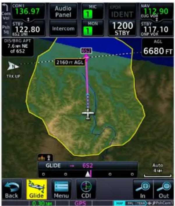
The Glide key replaces the Messages key when the Emergency page is not active.
Smart Glide calculates the glide route to a suitable destination airport. It then plots a direct course to the airport, replacing the existing flight plan.
Airport selection is based on specific characteristics and conditions. For more about how Smart Glide prioritizes airports, read Glide Destination Airport Criteria.
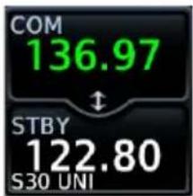
Standby COM frequency tunes to either the airport CTAF or tower frequency (if the active frequency is not already tuned).
Glide Destination Airport Criteria
Smart Glide will only suggest airports that meet the runway surface requirement. ^1 Any remaining airports are prioritized if:
• Weather conditions are MVFR or better ^2
• Estimated AGL altitude upon arrival is higher
• The runway is longer
Airports are de-prioritized if:
• The airport type is Private
• Weather conditions are IFR or lower ^2
- The longest runway is less than the configured minimum desired runway length
- Gust speed is higher than configured maximum gust speed ^1
^1 For aircraft specific information, consult the AFMS.
2 Weather rankings apply only to airports with weather reporting capability. Weather affects ranking only if the aircraft is equipped for weather data and weather information is current.

Map features automatically declutter and TOPO and Terrain overlays turn on if not already active. Map features revert to their previous settings when you cancel Smart Glide.
The yellow Smart Glide Range Ring automatically appears on all configured moving map displays (i.e., Map and HSI Map). Unlike the normal mode Glide Range Ring, this ring uses real-time data to calculate an estimated glide ratio based on current aircraft glide performance and available wind data. Shading outside the ring denotes areas not within estimated gliding distance.
An altitude label indicates the estimated arrival AGL for the airport. Runway extensions and AGL and DIS/ BRG APT user fields turn on if not already active.
HSI Map & MFD Map, GDU TXi

Smart Glide & Glide Range Ring
The Glide Range Ring uses color to indicate its current behavior. Under normal conditions, the ring is based on the configured glide ratio (cyan coloration). Upon Smart Glide activation, GTN Xi begins to measure the actual glide ratio and updates the ring accordingly (yellow coloration). If no aircraft configuration changes are made (e.g., flaps, gear), the measured glide ratio should reach steady state within 30 seconds of achieving stable glide. After configuration changes, it may take up to 30 seconds for GTN Xi to determine the new glide ratio.

While en route, GTN Xi navigates directly to the center of the airport.
Unless already completed, disengage the autopilot (if equipped) and land the aircraft when you receive the "Maneuver and Land" alert.
Smart Glide does not manage altitude. In order to make a safe landing, you may need to add drag and/or maneuver the aircraft off route before reaching the airport.
Flashing textual annunciations alert the pilot of warning, caution, and advisory conditions. These annunciations appear in a banner on the Emergency page and over the route display on Map. They turn solid or disappear after 5 seconds.
Advisory Alert Caution Alert
APPROACHING AIRPORT
Annunciates when the aircraft is 4 nm from airport.
AIRPORT OUT OF RANGE
Annunciates when the destination airport is unreachable.
Warning Alert
MANEUVER AND LAND
Annunciates when the aircraft is 2 nm from airport.
Flashing Alert Annunciations
• "AIRPORT OUT OF RANGE"1
- "APPROACHING AIRPORT"1
• "MANEUVER AND LAND"1
• "ALTN APT OUT OF RANGE" ^2
^1 Turns solid after 5 seconds.
^2 Disappears after 5 seconds.
For a list of possible Smart Glide alerts, refer to the annunciation tables in Smart Glide Alerts.
Enable Smart Glide Activation

Tapping Smart Glide Activation toggles activation between Enabled and Disabled. This key resides in the Emergency menu.
Disabling Smart Glide activation inhibits all methods of activation. An advisory message informs: "SMART GLIDE Disabled. Activation manually disabled by pilot."
To enable or disable Smart Glide activation:
From the Home page, tap Emergency > Menu > Smart Glide Activation.
Activate Smart Glide

NOTE
Contact a Garmin dealer if your installation does not provide access to emergency features.
FEATURE LIMITATIONS
Activation options are dependent upon installer configuration. If configured for an external switch, activation via the Direct To key is not available.
Emergency Page, GTN 650Xi

A message in the Emergency Mode Status window informs you that no emergency modes are active.
You may activate Smart Glide from any configured GTN Xi series navigator or MFD TXi series display unit. If installed, an external switch allows manual activation without the use of a touchscreen.
ACTIVATE SMART GLIDE VIA EXTERNAL SWITCH
From a dedicated external switch:
Press or toggle the dedicated switch (if configured).
ACTIVATE SMART GLIDE USING THE DIRECT TO KEY

Push and hold the Direct To key for 2 seconds. Activation occurs following a 3-2-1 countdown.
Hold for Smart Glide Activation in 3
ACTIVATE SMART GLIDE FROM THE EMERGENCY PAGE
WHERE TO FIND IT

flowchart
graph TD
    A["Home"] --> B["Emergency"]
    B --> C["Smart Glide"]
The Smart Glide activation key resides on the Emergency page of the configured GTN Xi series navigator or MFD TXi series display unit.
From the Home page:
Tap Emergency > Smart Glide.
View Smart Glide Status Information
Tapping Glide opens the Emergency page. Refer here for active route and longest runway details, the configured best glide speed for the aircraft, and available control options. This page is also accessible via the Emergency icon on the Home page.

When Smart Glide is active, this key replaces the Message key in the control bar.

The Message key returns once the Emergency page opens or when you cancel Smart Glide.
Emergency Page, GTN 750Xi

| 1 Mode Status Banner 5 Menu Key | ||
| 2 Active Route Display 6 Smart Glide Controls | ||
| 3 Longest Runway Information 7 Best Glide Speed Indication | ||
| 4 MSG Key (active) |
ACTIVE ROUTE DISPLAY
Glide → KIPT Williamsport Rgnl Arrival AGL: 2740 FT
Shows the active direct route for gliding to the destination airport. Information includes:
• Active airport identifier
- Airport name
• Estimated arrival AGL
Arrival AGL (or extra altitude) is the aircraft's estimated height above ground level when crossing the center of the airport.
Active Flight Plan, GTN 750Xi Series

Upon activation, Smart Glide replaces the active flight plan with a new direct course.
A message informs you that the flight plan is unavailable while Smart Glide is active.
GTN 650Xi SERIES
Active route identifiers appear on the Emergency page, active flight plan, Default Navigation page, and Map.
GTN 750Xi SERIES
Active route identifiers appear on the Emergency page, active flight plan, and Map.
Active route identifiers appear in multiple locations on configured Garmin displays. For details about the Smart Glide indications on these units, consult the associated pilot's guide.
LONGEST RUNWAY INFORMATION

NOTE
Wind data displays for airports without weather reporting if another airport with valid weather data is within 5 nm. The pilot is responsible for determining current wind direction and intensity.
View details about the destination runway.
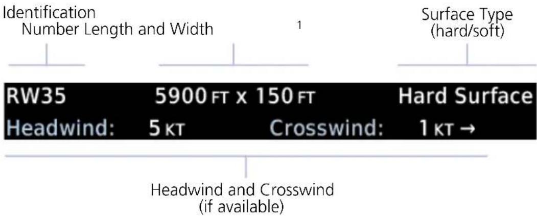
| Longest Runway | |||
| RW35 | 5900 FT x 150 FT | Hard Surface | |
| Tailwind: | 7 KT | Crosswind: | 3 KT ← |
Headwind data field changes color to indicate when tailwind conditions exist.
Advisory wind data received via datalink could be up to 90 minutes old.
"Wind data not available" Indication
This message displays in the absence of valid wind data.
Wind data not available
BEST GLIDE SPEED INDICATION
Shows the airspeed necessary to follow the calculated glide route.
Glide IAS: 110 KT
This value is configured by the installer and based on the published AFM/POH value for best glide speed at gross weight.
SMART GLIDE CONTROLS
Emergency Smart Glide Page

flowchart
graph TD
    A["Squawk 7700"] --> B["Map"]
    B --> C["Alternate Airport"]
    B --> D["Cancel Glide"]
Available control options allow you to:
- Direct tune emergency transponder code 7700
• View Smart Glide information on Map
• View and select alternate airports - Cancel Smart Glide
Tune Transponder

Tapping Squawk 7700 tunes the transponder to emergency code 7700. Use this function to immediately alert all air traffic control facilities in the area of your emergency.
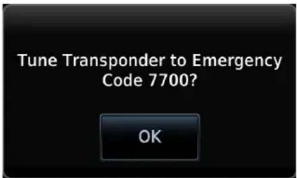
A pop-up message requests confirmation.
Tapping OK confirms the request.
Tapping Cancel closes the pop-up without alerting ATC.
View Smart Glide Information on Map

The Map key provides direct access to the moving map. Map shows a graphical representation of the active direct-to course for the suggested airport. Shading denotes areas estimated to be unreachable on glide.
Map, GTN 750Xi

To return to the Emergency page, tap Glide.
An alert banner displays textual warning, caution, and advisory annunciations. User fields indicating the aircraft's present AGL and its distance/bearing from the destination airport display on a solid black background for greater visibility. Other user fields declutter along with unnecessary map overlays.

If previously configured by the pilot, these two user fields remain in the same location once Smart Glide is activated. If not configured, they will appear in the upper corners as shown. If only one field is configured, the other will appear in the upper left or right corner.
Data removed during Smart Glide
- Airways
• Best Glide Airport indicator - Charts overlay
- Fuel Range Ring
- Heliports
- Intersections
• METAR product timestamp - NAV Range Ring
- NEXRAD
TOPO Scale - User fields other than AGL and DIS/BRG APT
• Visual Approach selector key
Data depicted during Smart Glide
- Airports
• Active glide route
• AGL and DIS/BRG APT user fields - Alert banner
• Estimated Arrival AGL label - Glide Range Ring
- Runway Extensions
- Terrain overlay
- TOPO overlay
GTN 750Xi SERIES
Active glide route identifiers appear on the GPS NAV Status bar.

Select an Alternate Airport on Map

You can select an alternate airport by tapping your finger directly on the map display. Selecting an airport icon within glide range opens an information banner. The Glide to Airport key replaces the Graphically Edit FPL key during Smart Glide mode.
FEATURE LIMITATIONS
Map displays up to 25 alternate airports within the estimated glide range. If more than 25 airports are within glide range, not all will be selectable for the destination airport. This feature is available only for airports in the database.
Map, GTN 650Xi

- Open Map to view all airports within glide range.

- Select the airport that best suits your needs.
- Tap Glide To Airport.

The active glide route adjusts to reflect the new destination. GPS NAV status bar updates to show the new route identifiers (GTN 750Xi Series only).
The new waypoint now appears as active atop the alternate airport list.
Find Alternate Airport

You may select an alternate airport directly from the map display or from the Alternate Airport list. Tapping Alternate Airport displays only the airports and runways within the projected glide range.

WARNING
Be aware that other airports or off airport landing areas may be available and more suitable but unknown to the Smart Glide system. The pilot must evaluate all options and choose the most appropriate course of action given the conditions.

NOTE
This system is intended to aid the crew in the initial avionics setup during a glide emergency and, if possible, assist the pilot in finding and navigating to a suitable airport within the estimated glide range of the aircraft. The pilot must make every effort to ensure that the system guidance is as desired.
FEATURE LIMITATIONS
• Lists up to 25 alternate airports within the estimated glide range
• Available only for airports in the database (e.g., private airports not in the database do not appear in the list)

Alternate airports appear until no longer within the projected range.
Runway length and surface type display for the longest runway at each airport.
Selecting an airport immediately creates a new direct route.
Tapping Glide or Back returns to the Emergency page.
Using the Direct To function to create and activate a new direct course automatically cancels Smart Glide.
Deactivate Smart Glide
You may deactivate Smart Glide at any time by tapping Cancel Glide.

A pop-up message requests confirmation.
Tapping OK confirms the request.
Tapping Back closes the pop-up without deactivating Smart Glide.
Upon deactivation:
• Map features revert to their previous settings
• Active Flight Plan restores and activates the previous flight plan route
- Aural message "Smart Glide canceled" alerts flight crew of deactivation
- Autopilot (if present) remains in its current active modes or reverts to ROL lateral mode
• CDI scale reverts to its previous setting
Smart Glide Alerts

WARNING
Do not rely solely upon Smart Glide data for guidance or decision-making. Smart Glide is intended only to enhance situational awareness during an emergency. Always manage any emergency in accordance with the approved flight manual or third-party operating instructions.
Textual annunciations alert the pilot of warning, caution, and advisory conditions related to Smart Glide. An aural voice message may play depending on the alerted condition.
Map, GTN 750Xi

Emergency Page, GTN 650Xi

Smart Glide Alert Banner
When an alert occurs:
- Textual annunciations appear in a banner on the Emergency page and over the route display on Map ^1
• Emergency page opens if another page is active ^2
• An aural voice message may play
| SMART GLIDE ALERTING | |
| ANNUNCIATION ALERT TYPE | CONDITION | AURAL MESSAGE | |
| MANEUVER AND LAND | Alert Type:WarningCondition:Aircraft is 2 nm from the destination airport's center. If not already doing so, the pilot should disconnect the autopilot (if equipped) and maneuver to manage altitude for a safe landing.Aural Message:"Maneuver and land. Airport X o'clock. Two miles."Alert Behavior:Flashing annunciation turns solid after 5 seconds. |
| NO AIRPORT IN RANGE | Alert Type:CautionCondition:Smart Glide activates with wings level and no airport within estimated glide range.Aural Message:"No airports within glide range." |
| AIRPORT OUT OF RANGE | Alert Type:CautionCondition:Destination airport is out of estimated glide range. May occur due to decreasing glide performance.Aural Message:"Airport out of range." (plays only once)Alert Behavior:Flashing annunciation turns solid after 5 seconds.Note: Estimated arrival AGL not available. |
| ALTN APT OUT OF RANGE | Alert Type:CautionCondition:The pilot selects an alternate airport via Map or the alternate airport list, but the airport becomes unreachable before Smart Guide can complete route calculation.Duration: 5 secondsAural Message: NoneAlert Behavior:Flashing annunciation disappears after 5 seconds. |
| None | Alert Type:CautionCondition:Smart Glide is active within 2 nm of the destination airport, the autopilot is engaged, and there is not enough altitude for the system to safely make a full circle descent with 2,000 ft remaining. Disengage autopilot to manage energy.Aural Message:"Disconnect autopilot." (plays 10 seconds after arriving within 2 nm of destination airport) |
| CALCULATING ROUTE | Alert Type:AdvisoryCondition:System is calculating the glide route to a suitable destination airport. Occurs during the following:Smart Glide activationSelection of an alternate destination (pilot override)When the CDI exceeds half of full-scale deviationAural Message:NoneNote:Estimated arrival AGL not available until route calculation is complete. |
| ACTIVE | Alert Type:AdvisoryCondition:Destination airport within range. Follow the displayed GPS route.Aural Messages:"Airport X o'clock. More than thirty miles.""Airport X o'clock. X miles.""Airport X o'clock. X and a half miles.""Airport X o'clock. One mile.""Airport X o'clock. Less than one mile." |
| None | Alert Type: AdvisoryCondition:Pilot attempts to activate Smart Glide via dedicated aircraft switch orDirect Tokey while the system is experiencing an error. On-screenSmart Glidekey not available.Aural Message: “Smart Glide disabled.” |
| APPROACHING AIRPORT | Alert Type: AdvisoryCondition:Aircraft is 4 nm from the destination airport’s center.Aural Message:“Approaching airport. X o’clock. Four miles.”Alert Behavior:Flashing annunciation turns solid after 5 seconds. |
| Smart Glide disabled until aircraft reaches 1,000 ft AGL | Alert Type: AdvisoryCondition:Pilot attempts to activate Smart Glide via dedicated aircraft switch orDirect Tokey while Smart Glide is disabled on ground or before reaching 1,000 ft AGL.Aural Message: “Smart Glide disabled. Low altitude.” |
| None | Alert Type: AdvisoryCondition:Pilot deactivates Smart Glide by tappingCancel Glide.Aural Message: “Smart Glide canceled.” |
| None | Alert Type: AdvisoryCondition:Pilot activates Smart Glide.Aural Message: “Smart Glide active.” |
| None | Alert Type: AdvisoryCondition:Smart Glide is active and current AGL reaches 500 ft.Aural Message: “Five hundred.”Note:Occurs only if unit is configured for Terrain Proximity. |
| None | Alert Type: AdvisoryCondition:Smart Glide is active and current AGL reaches 1,000 ft.Aural Message: “One thousand.”Note:Occurs only if no airports are within range. |
| None | Alert Type: AdvisoryCondition:Smart Glide is active and current AGL reaches 2,000 ft.Aural Message: “Two thousand.”Note:Occurs only if no airports are within range. |
| None | Alert Type: AdvisoryCondition:GFC transitions to autopilot engaged.Aural Message: “Engaging autopilot.” |
System Failure Alerts
In the case of a Smart Glide system failure (e.g., position data failure), discontinue use of Smart Glide for navigation. Use alternate forms of navigation and consider alternate landing areas.
When a Smart Glide system failure occurs, the Emergency page automatically opens if another page is active. In dual GTN Xi installations, this occurs on GTN 2 only.
These alerts do not appear on Map.
| SYSTEM FAILURE ALERTING | |
| ANNUNCIATION ALERT TYPE | CONDITION | AURAL MESSAGE | |
| TERRAIN DB ERROR | Alert Type:WarningCondition:Terrain database has an error.Aural Message:"Smart Glide failure. Consider alternate landing area." |
| NAVIGATION DB ERROR | Alert Type:WarningCondition:Navigation database has an error.Aural Message:"Smart Glide failure. Consider alternate landing area." |
| POSITION DATA ERROR | Alert Type:WarningCondition:Position or altitude data has an error.Aural Message:"Smart Glide failure. Consider alternate landing area." |
| FPL LOAD FAILURE | Alert Type:WarningCondition:Error occurs while attempting to calculate a route.Aural Message:"Smart Glide failure. Consider alternate landing area." |
Emergency Descent
Emergency Descent Mode (EDM) assists pilots of pressurized aircraft in the event of cabin depressurization. Depending on installation type, GTN Xi provides access to this feature via the Emergency page.
FEATURE REQUIREMENTS
• GDU 700( )/1060 PFD (host)
• GFC 600 autopilot configured for EDM
For automatic activation, GFC 600 must be configured with an air data module that provides cabin pressure monitoring.
FEATURE LIMITATIONS
Availability and the manner in which activation occurs (manual or automatic) are dependent upon configuration.
EDM Activation
Emergency Page, GTN 650Xi

If configured for cabin pressure monitoring, the system monitors cabin pressure once EDM is armed. EDM is considered armed when:
- Autopilot is active
• Aircraft is above 15,000 ft MSL
Once armed, activation may occur manually or automatically.
EDM is a function of GDU TXi. For more information regarding functionality, consult G500(H)/G600/G700 TXi Pilot's Guide.
Manual Activation
WHERE TO FIND IT
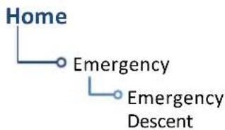
You can activate EDM one of two ways:
From the Home page:
Tap Emergency > Emergency Descent.
From a dedicated external switch:
Enable the dedicated switch (if configured).
Automatic Activation
If the aircraft experiences decompression and cabin altitude increases beyond the threshold configured for the aircraft, the system automatically triggers EDM.
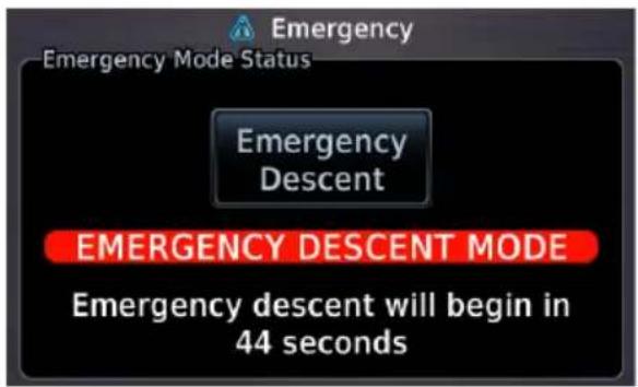
Warning and timer indications are identical to those appearing on the Emergency page of the host GDU TXi.
Upon Activation
The status window displays a warning message and timer.
Emergency descent occurs once the timer expires. This delay can range from 10 to 60 seconds.

Status messages inform you of mode status.
If manually activated, you may skip the delay and activate EDM immediately by selecting Emergency Descent again.
INTENTIONALLY LEFT BLANK
7 Services
SIRIUSXM AUDIO ENTERTAINMENT....7-3
CONNEXT SERVICES....7-9
SERVICES APPS & FUNCTIONS

Optional satellite services are available when your unit is connected to a GDL 69/69A datalink receiver (Music) or GSR 56 Iridium transceiver (Phone, SMS Text, and Position Reports).

Phone
- Place telephone calls
- Set up call notifications

SMS Text
• Compose & send messages
- Receive messages
- Set up text notifications

Music
- Tune SXM radio
- Adjust radio volume

Position Reports
- Set up automatic reporting
• Transmit reports manually

Contacts
- Manage contacts
- Call or message contacts
SiriusXM Audio Entertainment

The Music app provides controls for tuning and presetting satellite radio music channels. This subscription-based service is available through SiriusXM Satellite Radio.
FEATURE REQUIREMENTS
• GDL 69A SiriusXM receiver
• Active SiriusXM Satellite Radio subscription

Music Features
| 1 Channel Selection Key 5 Browse Categories Key |
| 2 Channel Seek Controls 6 Volume Key |
| 3 Preset Group Key 7 Current Selection Info |
| 4 Preset Channel Keys 8 SXM Signal Level |
SiriusXM Audio Activation

The GDL 69A Status page provides information necessary for activating SiriusXM Satellite Radio services.
OPEN GDL 69A STATUS PAGE
You can access this page one of two ways.
From the External LRUs list:
Home > System > External LRUs, locate GDL 69A and tap More Info

From the Music page:

Home > Services > Music > Status
COMPLETE SUBSCRIPTION ACTIVATION
- Navigate to the GDL 69A Status page.
- Verify activation. For entertainment subscriptions only, the status page displays your Audio Radio ID and subscription information.
- Tap Menu > Lock Activation > OK.
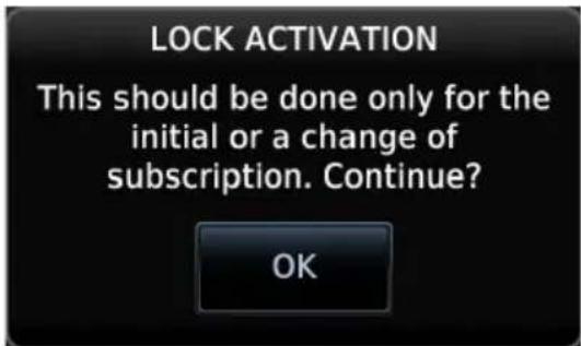
Adjust Radio Volume

Tap the Volume key to adjust or mute music volume.

Mute On
Mute toggles radio audio output on or off.
Direct Channel Tuning
SiriusXM Radio Options
• Channels 0 to 999
- Categories 0 to 63
Music provides both numeric entry and channel seek functionality.
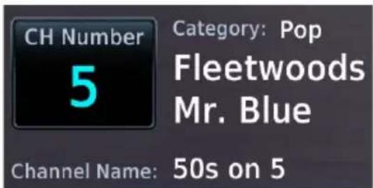
Tapping CH Number allows you to enter a specific radio channel by number. The channel, song, artist, and music category display for the current selection.

Seek controls allow you to step to the next or previous channel.
Browse Music Channels
Tapping Browse allows you to scroll through a list of all available channels.
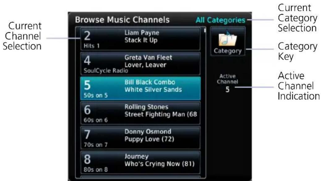

To filter the list according to a specific genre, tap Category and then choose one of the available music types.
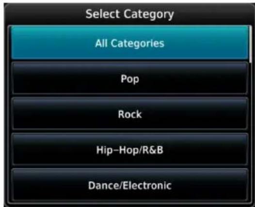
To choose all available types, select All Categories.
Assign Channel Presets
Quick Tuning Options
• Choice of three preset groups: XM 1, XM 2, XM 3
- Assign up to five preset channels per group
For quick tuning, use presets to store multiple channels in the unit's memory.
ASSIGN A CHANNEL PRESET
- Select a channel.
- Tap Presets until the desired preset group displays.
- Tap and hold any preset key for three seconds.

Unassigned Preset Keys
SELECT A PRESET
- Select a preset group (XM 1, XM 2, or XM 3).
- Tap any assigned preset key.

Assigned Preset Keys
XM Data Link Failure
If the Audio Radio ID and/or Data Radio ID do not display during GDL 69A operation, contact a Garmin dealer.

Troubleshooting the GDL 69/69A Datalink Receiver
GTN serves as the control head for your remotely mounted GDL 69/69A. In the event of a receiver failure:
• View datalink receiver status on the GDL 69 Status page
• Verify the SiriusXM Satellite Radio subscription is active
- Check circuit breakers to ensure power is applied to the receiver
It may take several minutes for all subscription data to become available after unit power up.
For more information, consult GDL 69/69A SiriusXM Satellite Radio Activation Instructions. For subscription activation instructions, visit https://www.siriusxm.com/sxmaviation.
Connext Services


Optional 2-way text and voice communication and GPS-referenced position reporting apps are available through the Iridium satellite system.


FEATURE REQUIREMENTS
• GSR 56 satellite datalink
• Iridium satellite network subscription
- Valid phone number or email address for 2-way text messaging via SMS
FEATURE LIMITATIONS
• Applicable to the Iridium satellite telephone system only
Phone

Make and receive telephone calls using the Iridium satellite communications network.
WHERE TO FIND IT

flowchart
graph TD
    A["Home"] --> B["Services"]
    B --> C["Phone"]
Phone is accessible from the Services menu.
Incoming calls generate a pop-up, allowing you to accept or ignore the call without leaving the current screen.

flowchart
graph TD
    A["1: Status"] --> B["Idle"]
    B --> C["Phone Number 1234567890"]
    C --> D["Call"]
    C --> E["End Call"]
    D --> F["Volume 40%"]
    E --> G["Suppress Visuals On During APR/MAPR/TERM"]
    F --> H["In-Call Distribution"]
    G --> H
    H --> I["Pilot"]
    H --> J["Co-Pilot"]
    H --> K["Passenger"]
Phone Page

Phone Pop-up
| 1 Phone Status Window 5 Volume Controls | |
| 2 Phone Number Entry Key 6 Suppress Visuals Function | |
| 3 Call Key 7 | In-call Distribution Controls ^1 |
| 4 End Call Key (inactive) | |
^1 Available only when interfaced with a GMA 35 Audio Panel.
Phone Volume

Tap the Volume keys to set telephone volume to the preferred level.
Volume displays as a percentage of the maximum volume, with 0% being muted and 100% being maximum volume.
These controls are grayed out when the function is not available.
Volume controls are available only when Phone is:
- Idle
- Connected
- Changing Volume
Phone Status Annunciations

Refer to the Status window for current call time and operating status.
| ANNUNCIATION MEANING | |
| Idle Phone is not communicating via GSR 56. | |
| Initializing GSR 56 and its driver are initializing. | |
| Call Time ##:## Duration of the current telephone call. | |
| Connected GSR 56 is connected to the dialed number. | |
| Connecting Call | GSR 56 is in the process of connecting to the dialed number. |
| Changing Volume The volume level on GSR 56 is fluctuating. | |
| Busy | Phone is in use by another service. Call may not complete. |
| Dialing G | SR 56 is dialing the number. |
| Incoming Call GSR 56 is receiving a call. | |
| Hanging Up GSR 56 is disconnecting from the call. | |
| Unavailable GSR 56 is not usable by the Iridium phone system. | |
Suppress Visuals
FEATURE LIMITATIONS
• Applicable only to calls using the Iridium telephone system

Enabling this function inhibits visual indications of incoming calls and text messages.
Tap Phone > Suppress Visuals, and select from the following options.
Off On
No suppression. You may transmit and receive calls normally through the Iridium phone.
Suppression active. Incoming call/text pop-up indication will not resume until you turn suppression off.
On During APR/MAPR/TERM
Suppression active during approach, missed approach, and terminal operations only.
Suppression does not affect:
• Audible indications (i.e., phone ringer, incoming SMS chime)
- Outgoing calls
• Answering incoming calls
Garmin recommends inhibiting audio from GSR 56 when the Iridium phone is not in use.
In-Call Distribution
FEATURE REQUIREMENTS
• GMA 35 Audio Panel
Distribute telephone audio to selected crew and/or passenger positions. These include:
- Pilot • Co-Pilot • Passenger
You may toggle the telephone audio off to any position at any time.
Outgoing Calls

Call someone directly or dial an existing contact in your contact list.
MAKE A CALL
Tap Phone > Phone Number.
From here you may:
- Direct dial a number: Type the number you wish to call and then tap Enter.
- Dial an existing contact: Tap Contacts, select a name from the list, then tap Call.
To cancel the call, tap End Call.
DATA ENTRY

If it is necessary to enter data during a call (e.g., an automated phone menu prompts you to make a numeric selection), tap Touchtone Entry and enter the value using the provided keypad.
Incoming Calls
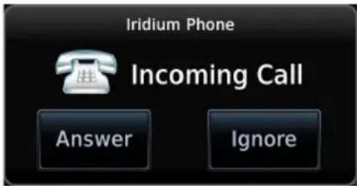
Incoming calls generate a status message. Options allow you to accept or ignore the call.
ACCEPT A CALL
Tap Answer. Status window shows the call as "Connected" and the cumulative call timer begins.
Upon accepting a call, you have the following options.
- Adjust call volume: Use volume controls to set the level according to preference.
• Distribute telephone audio: Select Pilot, Co-Pilot, and/or Passenger.
• Hang up: Tap End Call.
IGNORE A CALL
Tap Ignore. This disconnects the call (i.e., hangs up).
SMS Text

Send and receive text messages via phone or email through your GSR 56 phone connection.
WHERE TO FIND IT
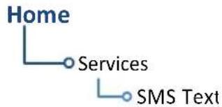
flowchart
graph TD
    A["Home"] --> B["Services"]
    B --> C["SMS Text"]
Message tabs allow for management of all incoming and outgoing messages. Each tab displays a message list.
Notations indicate the status of messages within each list. The total number of messages annunciates at the bottom of the pane.

Inbox Lists up to 250 received messages.
Drafts Lists all saved outgoing messages.
Outbox Lists all sent messages pending transmittal.
MESSAGE ICONS & NOTATIONS

TXing
Draft message pending transmittal

Sent
Sent message (outbox)

New
New message (inbox)

Send/Resend
Send message

Open
Message has been read

Failed
Failed to send
Message Filtering & Setup Options
SMS Text Messaging
Menu

flowchart
graph TD
    A["Time"] --> B["Address"]
    B --> C["Mark All As Read"]
    C --> D["Delete All Messages"]
    D --> E["Suppress Visuals"]
    E --> F["Off"]
    E --> G["On"]
    E --> H["On During"]
    H --> I["APR/MAPR/TERM"]
Tap Menu to access SMS text messaging filtering and setup options.
- Sort messages according to time or address
• Suppress incoming call indications
• Mark or delete all messages
| Sort Messages By Time | Organize messages according to time. The most recent entry appears at the top of the list. |
| Sort Messages By Address | Organize messages according to address. Entries are listed in alphabetical order. |
| Mark All As Read | Mark all inbox messages as read. |
| Delete All Messages | Remove all messages from each tab simultaneously. This command requires user confirmation. |
| Suppression | Enable/disable the suppression function. Options: Off, On, On During APR/MAPR/TERM |
Send a Text Message

Compose and send a new text message via telephone or email.

-
Tap Compose.
-
Select the message destination: Tap To, then choose either Phone Number or Email Address.
-
Specify the recipient's phone number or email address. For existing contacts, tap Contact and select the recipient's name from the list.
-
Tap Message and then type the message content.


flowchart
graph TD
    A["Draft Message Options"] --> B["Delete"]
    A --> C["Save"]
    A --> D["Send"]
Once you begin to compose your message, you have the following options.
- Delete the unsent message: Tap Delete.
- Save the message as a draft: Tap Save.
- Send the message: Tap Send.
Once sent, the message automatically appears in your outbox. Pending messages remain in your outbox until they complete transmittal.
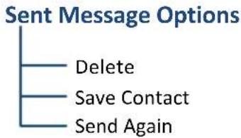
flowchart
graph TD
    A["Sent Message Options"] --> B["Delete"]
    A --> C["Save Contact"]
    A --> D["Send Again"]
Open a sent message if you wish to:
- Delete it from your outbox: Tap Delete.
- Save the phone number or email address: Tap Save Contact and enter the new contact name.
- Resend after it failed to send on the first attempt: Tap Send Again.
MESSAGE FAILED TO SEND

Failed messages remain in the outbox until they are resent or deleted. The number of failed messages annunciates below the tab name.

To resend the message:
Select the message from the outbox list, then tap Send Again.
If the message fails to send, you can tap Delete to remove it from the list.
Receiving Text Messages
To view a new text message, tap Inbox and select the message from the list.
Received Message Options
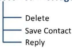
flowchart
graph TD
    A["Delete"] --> B["Save Contact"]
    B --> C["Reply"]
All received messages allow the following options.
- Delete the message from your inbox: Tap Delete.
- Add the sender to your contact list: Tap Save Contact and enter the new contact name.
- Compose a response: Tap Reply.
Position Reports

Enable automatic GPS-referenced position reports for continuous monitoring of aircraft status while en route. This function collects system variables and transmits them at predefined intervals through the GSR 56.
WHERE TO FIND IT

flowchart
graph TD
    A["Home"] --> B["Services"]
    B --> C["Position Reports"]
Set the report function to transmit automatically based on a schedule of your choice, or send a report immediately by tapping Send Report.
Position Reporting Status Annunciations
Position reporting enables when the aircraft is in the air. A window displays the status of GSR 56 functions.
| Status | |
| Time Until Transmit | 14:48 |
| Reporting Status | Transferring |
| Reports in Queue | 1 |
| ANNUNCIATION MEANING | |
| Idle GSR 56 reporting function is not in use. | |
| Idle - On Ground | GSR 56 reporting function is not in use.Aircraft is on the ground. |
| Initializing GSR 56 and its driver are initializing. | |
| Transferring GSR 56 is transmitting a position report. | |
| Unavailable GSR 56 is not usable by the reporting system. | |
GSR 56 Product Information Reporting:
Once GTN powers up, it takes 90 seconds for the GSR 56 to report its serial number. During this period, GSR 56 product information status shows as Waiting.
Counters & Timers
Time Until Transmit Reports in Queue
- Countdown timer
• Shows time remaining until the next data transmission -
Dashes indicate when the aircraft is on the ground
-
Counter
• Shows the number of reports waiting in queue
Position Reporting

Tapping Automatic Reporting toggles the automatic position reporting function on or off.
SPECIFY A REPORT PERIOD
- Enable automatic reporting.
- Tap Report Period and specify a reporting interval between 2 and 60 minutes.
SEND A REPORT
- Disable automatic reporting.
- Tap Send Report.
Contacts

Store up to 250 contacts. Call by telephone or send text messages via SMS or email.
WHERE TO FIND IT
Scroll the list or search by name. Contact names are in alphabetical order.

flowchart
graph TD
    A["Home"] --> B["Services"]
    B --> C["Contacts"]
Create a Contact
- Tap Add.
- Enter the contact's name, phone number, and/or email address using the appropriate data entry keys.
- Tap Save Contact.
The new contact appears in the list.
3/250
A field in the upper right corner of the page indicates the total number of contacts in the list.
When direct dialing or storing a contact's phone number, dial "1" before the area code and seven-digit telephone number.
1 + area code + seven-digit telephone number
Find a Contact

- Tap Search.
- Type the contact's name and tap Enter.
The page displays the matching entry.
To return to the full list view, tap Clear Search.
Contact Options




Selecting an existing contact opens a menu. Options allow you to:
• Dial a contact's telephone
- Send a text message via phone or email
• Edit contact information
- Delete a contact from the list
DELETE A CONTACT
- Select a name from the contact list.
- Tap Delete.
- Confirm the request.
INTENTIONALLY LEFT BLANK
8 Messages
ADVISORY MESSAGES....8-2
Advisory Messages
Message List

Advisories are system-related messages relative to the display.
- Most recent advisories appear at the top of the message list
• View-once advisories remain in queue until viewed by the pilot - Persistent (or conditional) advisories remain active until the indicated condition is resolved
Dual GTN Installations
Advisory messages are not crossfilled between GTN units. Each unit displays messages based on the data it receives. This may result in duplicate messages between units.
Always view the messages on both GTNs to ensure that all information is received.
Message Key
This key displays in the unit's control bar when an advisory condition is present. Tapping MSG once displays an advisory list. Tapping it again acknowledges all active advisories and closes the list.
The key no longer displays after all active advisories are cleared.

The key flashes when a new advisory is present.

It turns solid once all active advisories are acknowledged.
Airspace Advisories
Alerted airspace types are based on pilot settings in the Airspace Alerts page. These advisories are informational only. No action is necessary.
| ADVISORY CONDITION | |
| AIRSPACE ALERTInside airspace. | Aircraft is inside alerted airspace. |
| AIRSPACE ALERTAirspace within 2 nm andentry in less than 10 minutes. | Alerted airspace is within 2 nm of the path andprojected to enter in less than 10 minutes. |
| AIRSPACE ALERTAirspace entry in less than10 minutes. | Aircraft is projected to enter alerted airspacein less than 10 minutes. |
| AIRSPACE ALERTWithin 2 nm of airspace. | Alerted airspace is less than 2 nm from theaircraft. May not be projected to enter theairspace. |
Database Advisories
ADVISORY CONDITION CORRECTIVE ACTION
| CROSSFILL ERRORGTN Navigation DBmismatch. | Navigation databases donot match betweenGTNs, resulting in a lossof communicationbetween the two units. | Verify that the databaseversion specified by bothGTNs is up to date. Updatethe database if needed. |
| DATABASEDatabase not unlocked for this system. | A system ID mismatchbetween the databaseand the system unitresults in a databaseinstallation failure. | Re-download and install alldatabases. Contact a Garmindealer for support. |
| DATABASETerrain or Obstacledatabase not available. | The Terrain or Obstacledatabase is missing orcorrupt. | Re-download and install theindicated database. Contact aGarmin dealer for support. |
| DATABASETerrain displayunavailable forcurrent location. | Terrain/TAWS functionunavailable. Terraindatabase cannot provideelevation at the currentGPS position. Aircraft isoutside the databasecoverage area. | Load appropriate coveragearea onto the externaldatacard. |
| DATABASEVerify user-modifiedprocedures in storedflight plans arecorrect. | Navigation databaseupdates and the storedflight plan containsuser-modifiedprocedures. | Verify the procedures arecorrect. |
| DATABASEVerify airways instored flight plan arecorrect. | The stored flight plancontains an airway that isinconsistent with thecurrent navigationdatabase. | Verify all airways are correct. Ifnecessary, reload airways tothe stored flight plan routes. |
| DATABASEA procedure hasbeen modified in acataloged flightplan. | Database update causesflight plan to exceed100 waypoint limit.Procedure is removed ortruncated as a result. | Verify cataloged flight planand procedures are correct. Ifnecessary, reload proceduresto the stored flight planroutes. |
ADVISORY CONDITION CORRECTIVE ACTION
| DATABASEChart database valid until [date]. | The charts database is approaching expiration. | Verify expiration date:Home > System >System Status > Active tabIf available, load the next cycle of the charts database into standby. |
| The charts database is expired. | Update the database if necessary for operation. | |
| DATABASEChart function unavailable. | Charts database verification failure. | Re-download and install the indicated database. Contact a Garmin dealer for support. |
| DATABASEChart database incomplete. Some charts may be unavailable. | Charts database verification failure. | Re-download and install the indicated database. Contact a Garmin dealer for support. |
| DATABASETerrain database is not installed, is corrupt, or is not valid for this system. | Terrain database is not available at system startup. Terrain information and alerts do not display.The database may be corrupt, not present, or not authorized for the unit. | Re-load the database on the external datacard. |
| DATABASEChart Streaming unavailable. Using installed chart database from datacard. | Chart streaming not available. GTN reverted to the currently installed charts. | Open the System Status page and check database synchronization status. If the problem persists, contact a Garmin dealer for support. |
| DATABASESYNC in progress.View System Status page for more info. | Database synchronization is in progress. | Wait for database synchronization to complete.Restart GTN to use new databases. |
| MAGNETIC VARIATIONAircraft in area with large mag var. Verify all course angles. | Magnetic variation flagged as unreliable in the MagVar database.Typically occurs when operating at high latitudes that do not support a magnetic NAV angle. | Verify that the geographical region supports navigation based on magnetic variation. |
Datalink Advisories
ADVISORY CONDITION CORRECTIVE ACTION
| DATALINKADS-B In fault:UAT receiver. | ADS-B In source detectsa UAT receiver fault. | Service required.Contact dealer for support. |
| DATALINKADS-B In fault:1090 receiver. | ADS-B In source detectsa 1090 receiver fault. | |
| DATALINKFIS-B weather hasfailed. | FIS-B receiver reports afailure. FIS-B productsmay not display. | |
| DATALINKGDL 69 isinoperative orconnection to GTNis lost. | GTN losescommunication withGDL 69/69A. Datalinkdata not available. | 1. Close the GDL 69/69Acircuit breaker.2. Verify that the GDL 69/69Aunit is receiving power.3. Ensure the aircraft has aclear view of the sky.4. Verify subscription status isactive (Home >System>External LRUs, locateGDL 69/69A and tapMore Info).5. Contact dealer for service. |
| DATALINKGDL 88 ADS-Bfailure. Unable totransmit ADS-Bmessages. | GDL 88 cannot transmitthe ADS-B message dueto an internal failure oran antenna failure. | Service required.Contact dealer for support. |
| DATALINKGDL 88 ADS-B fault. | GDL 88 detects a faultwith one of theUAT/1090 antennas. | |
| DATALINKGDL 88 ADS-B fault.Pressure altitudeinput is invalid. | GDL 88 losescommunication with thepressure altitude source. | |
| DATALINKGDL 88 ADS-B is nottransmittingposition. Check GPSdevices. | GDL 88 detects a positioninput fault. |
ADVISORY CONDITION CORRECTIVE ACTION
| DATALINKGDL 88 configuration module needs service. | GDL 88 detects a configuration module fault. | Service required.Contact dealer for support. |
| DATALINKGDL 88 control input fault. Check transponder is in correct mode. | GDL 88 loses communication with the transponder. | |
| DATALINKGDL 88 is inoperative or connection to GTN is lost. | GTN loses communication with the datalink device (GDL 88). Traffic and/or FIS-B weather data not available. | |
| DATALINKGDL 88 needs service. | GDL 88 reports an internal fault. | |
| DATALINKGSR 56 data services inoperative; registration required. | GSR 56 requires registration. GSR weather and position reporting services are not available. | 1. Register the GSR 56.2. Activate a Connext subscription.3. Contact dealer for service. |
| DATALINKGSR 56 is inoperative or connection to GTN is lost. | GTN loses communication with GSR 56. GSR weather, position reporting, and phone services are not available. | 1. Close the GSR 56 circuit breaker.2. Verify that the GSR 56 unit is receiving power.3. Contact dealer for service. |
Flight Plan Advisories
| ADVISORY CONDITION CORRECTIVE ACTION | ||
| FLIGHT PLANIMPORTFlight plan import failed. | Unit unable to decode flight plan contents.Wireless import of the requested flight plan not possible. | Check for proper operation of all necessary components.If the problem persists,contact dealer for service. |
| FLIGHT PLANIMPORTFlight plan import failed. Catalog is full. | The flight plan catalog is full. Wireless import of the requested flight plan not possible. | Delete any unnecessary flight plans from the catalog. |
| FLIGHT PLANIMPORTNew imported flight plan(s) available for preview. | Unit receives the specified number of flight plans via the import function. They are available for viewing on the Preview page. | No action necessary. |
| FLIGHT PLANIMPORTChanges to active route are disabled. | Unit receives a flight plan from G3X Touch, but the External FPL Crossfill function is off. | Service required.Contact dealer for support. |
| FLIGHT PLANIMPORTGDU disconnected.External flight plan crossfill inoperative. | Unit loses communication with the G3X Touch. | Verify that the GDU is on.Contact dealer for service. |
| FPL WAYPOINTLOCKEDStored flight plan waypoint is not in current navigation database. | Current navigation database no longer contains a stored flight plan waypoint. | Verify all stored cataloged flight plans and procedures.Modify stored flight plans as necessary to include waypoints that are in the current navigation database. |
| FPL WPT MOVEDStored flight plan waypoint has changed location. | A waypoint in a stored flight plan moved by more than 0.33 arc minutes from its previous position. | Verify stored cataloged flight plans and procedures.Modify stored flightplans as necessary to include waypoints that are in the current navigation database. |
ADVISORY CONDITION CORRECTIVE ACTION
| LOCKED FLIGHT PLANCannot activate a flight plan containing a locked waypoint. | User is attempting to activate a flight plan that contains a locked waypoint. | Modify flight plan as necessary to include waypoints, procedures, and airways that are in the navigation database. |
| OBSOBS is not available due to dead reckoning or no active waypoint. | OBS not supported in dead reckoning mode. Requires an active waypoint. | No action necessary. |
| PARALLEL TRACKParallel track not supported for leg type. | Parallel track not supported on active leg type. | |
| PARALLEL TRACKParallel track not supported for turns greater than 120 degrees. | Parallel track not supported for turns greater than 120 degrees due to the acute angle. | |
| PARALLEL TRACKParallel track not supported past IAF. | Parallel track not supported on approaches. | |
| STEEP TURNSteep turn. Aircraft may overshoot course during turn. | The flight plan contains an acute course change ahead. Following the guidance requires a bank in excess of normal. If coupled, the autopilot may not be able to execute the steep turn. | Slowing the aircraft may shallow the turn. |
GPS/WAAS Advisories
ADVISORY CONDITION CORRECTIVE ACTION
| GPS NAVIGATION LOSTInsufficient satellites. Use other navigation source. | GPS position lost due to lack of satellites. | Wait for GPS satellite geometry to improve. Ensure the aircraft has a clear view of the sky. Use a different GPS receiver or a non-GPS based source of navigation.Contact dealer for service. |
| GPS NAVIGATION LOSTErroneous position. Use other navigation source. | GPS position lost due to erroneous position. | Use a different GPS receiver or a non-GPS based source of navigation. Contact dealer for service. |
| GPS RECEIVERLow internal clock battery. | GPS receiver indicates that its clock battery is low. May experience delay when attempting to acquire GPS position. | Contact dealer for service. |
| GPS RECEIVERGPS receiver needs service. | GPS receiver reports that it requires service. GPS module functionality may be unavailable. | Use a different GPS receiver or a non-GPS based source of navigation. Contact dealer for service. |
| GPS RECEIVERGPS receiver has failed. Check GPS coax for electrical short. | Internal communication to the GPS receiver is inoperative. | Use a different GPS receiver or a non-GPS based source of navigation. Contact dealer for service. |
| GPS SEARCHINGSKYEnsure GPS antenna has unobstructed view of the sky. | GPS receiver is acquiring position and may take longer than normal.Typically occurs when the unit is powered on after installation or being off for several weeks. | No action necessary. |
| LOSS OF INTEGRITY (LOI)Verify GPS position with other navigation equipment. | GPS board reports LOI.Antenna may be shaded from satellites. | Ensure the aircraft is clear of hangars, buildings, trees, etc. Use a different GPS receiver or a non-GPS based source of navigation. If the problem persists, contact dealer for service. |
Navigation Advisories
ADVISORY CONDITION CORRECTIVE ACTION
| ABORT APPROACHGPS approach is no longer available. | GPS approach not available. GPS unable to provide approach level of service (i.e., LPV, LNAV, LNAV+V, or L/VNAV). | Initiate a climb to the MSA or other published safe altitude, abort the approach, and execute a non-GPS based approach. |
| APPROACHDOWNGRADEGPS approach downgraded.Use LNAV minima. | Approach downgraded from LPV or LNAV/VNAV to an LNAV approach.Vertical guidance no longer available. | Continue to fly the approach using published LNAV minimums. |
| APPROACH NOTACTIVEApproach guidance not available. | GPS approach could not transition to active (e.g., the unit remains in TERM as it does not have the required HPL/VPL for LNAV). | Abort the approach and then execute a non-GPS based approach. |
| CDI/HSI FLAGMain lateral/vertical flag on CDI/HSI is inoperative. | Main Lateral/Vertical Superflag output is off due to an overcurrent condition. | Verify course guidance is valid and correct by crosschecking the unit's on-screen CDI with other navigational equipment.Contact dealer for service. |
| CDI SOURCESelect appropriate CDI source for approach. | Aircraft is on a GPS approach, but CDI is set to VLOC. | Select the appropriate CDI source for the approach. |
| Aircraft is on VLOC approach, CDI is set to GPS, and aircraft is less than 2 nm from the FAF. | ||
| HOLD EXPIREDHolding EFC time has expired. | It is past the specified Expected Further Clearance time for the user-defined hold. | No action necessary.Consider contacting ATC as appropriate. |
| MAGNETIC NORTH APPROACHVerify NAV angles are referenced to Magnetic north. | The loaded approach is magnetic, but the NAV angle reference is not. | Change NAV angle setting to Magnetic. |
ADVISORY CONDITION CORRECTIVE ACTION
| NAV ANGLENAV angles are referenced to True north (T). | NAV angle is set to True. | No action necessary. |
| NAV ANGLENAV angles are referenced to a user set value (U). | NAV angle is set to User. | |
| NON-WGS84 WAYPOINTLocation may be different than where surveyed for. | The active waypoint does not reference the WGS84 datum. | No action necessary.For more information, read “Points About Non-WGS84 Waypoints” in this section. |
| SELECT FREQUENCYSelect appropriate NAV frequency for approach. | The active NAV frequency is not correct for the approach procedure. | Enter the correct frequency into the active NAV frequency window. |
| SET COURSESet Course on CDI/HSI to. | The selected course on the CDI/HSI does not match the current desired track. | Set the CDI/HSI selected course to the current desired track. |
| TOD/BODin 1 minute. | Aircraft will reach top/bottom of descent in 1 minute. | No action necessary. |
| TRUE NORTH APPROACHVerify NAV angles are referenced to True north (T). | The loaded procedure references True north and the active leg has a published True north reference. | Verify the NAV angle is set to True north. |
| VISUAL APPROACH NOT ACTIVEApproach guidance not available when direct-to runway. | A direct course was created to the runway waypoint. Approach guidance not available. | Reactivate the approach or cancel the direct course. |
| VNAVUnable to reach vertical waypoint. | Altitude constraint cannot be reached based on current ground and vertical speeds. | Attempt to intercept vertical path by adjusting aircraft altitude. |
ADVISORY CONDITION CORRECTIVE ACTION
| VNAVUnavailable.Upcoming flight plan leg not supported. | The lateral flight plan contains a procedure turn, vector, or other unsupported leg type prior to the active vertical waypoint. | Treat the flight plan segments before and after the affected leg as separate vertical profiles. GTN cannot provide automatic guidance between the two segments. |
| VNAVUnavailable.Excessive cross track error. | Crosstrack exceeds limit, causing vertical path guidance to become invalid. | Navigate within 10 nm of flight plan centerline, or edit flight plan to allow for vertical navigation. |
| VNAVUnavailable.Excessive track angle error. | Track angle error exceeds limit, causing vertical path guidance to become invalid. | Navigate within 70° of active flight plan course. |
| VNAVUnavailable.Barometric altitude lost. | A loss of data from the barometric altitude sensor causes vertical path guidance to become invalid. | Contact dealer for support. |
| WAYPOINTArriving at [wpt name]. | Pilot set the arrival alarm and is within the specified distance. | Informational only.No action necessary. |
Points About Non-WGS84 Waypoints
• There are several types of geodetic datums that a waypoint can reference.
- TSO-C146 requires that all waypoints reference the WGS84 datum, but allows for navigation to coordinates not compliant with this standard as long as the pilot is notified of the potential difference in location.
- Not all waypoints in the navigation database reference the WGS84 datum. For some of these coordinates the reference datum is unknown. In such cases, the "Non-WGS84 Waypoint" advisory displays.
- Garmin cannot determine the exact proximity of a non-compliant waypoint to the WGS84 datum in use by the system. Typically, the distance is < 2 nm.
• Most non-WGS84 waypoints are outside of the United States.
Pilot Specified Advisories
These advisories display when the associated timer expires or reaches a preset value. They are informational only. Other than acknowledging the message, no action is necessary.
| ADVISORY CONDITION | |
| SCHEDULED MESSAGE. | The custom message timer expired. |
| TIMERTimer has expired. | The generic timer is past its preset value. |
Smart Glide Advisories
The unit automatically inhibits Smart Glide when the required conditions are not met.
ADVISORY CONDITION CORRECTIVE ACTION
| REMOTE KEYSTUCKEngage/DisengageSmart Glide key is stuck. | System detects the indicated remote key is depressed for at least 30 seconds. It will now ignore this input. | Push the indicated key again.If it remains stuck, contact dealer for service. |
| SMART GLIDEDisabled.Activation manually disabled by pilot. | Pilot disables Smart Glide activation by toggling theSmart Glide Activationkey to Disabled. | Re-enable Smart Glide activation. From the Home page, tapEmergency>Menu, and toggle theSmart Glide Activationkey to Enabled. |
| SMART GLIDEDisabled.Erroneous activation detected. May be re-enabled via Emergency page menu. | System disablesSmart Glide activation because the feature exceeded the maximum number of activations allowed within a one minute period. System allows up to three activations per minute. | |
| SMART GLIDEDisabled.System initializing. | System disablesSmart Glide activation for 40 seconds after unit power up. | Wait 40 seconds for system initialization to complete, then re-attempt activation. |
| SMART GLIDEUnavailable above 11,000M/36,000FT.1 | Aircraft altitude is above the indicated MSL. | Descend below 11,000 m/36,000 ft and attempt to activate Smart Glide. |
ADVISORY CONDITION CORRECTIVE ACTION
| SMART GLIDEUnavailable.AHRS roll angle lost. | GTN Xi is not receiving a valid roll angle from the AHRS source. | Contact dealer for service. |
| SMART GLIDEUnavailable.Barometric altitude lost. | GTN Xi is not receiving valid barometric altitude. | |
| SMART GLIDEUnavailable.Crossfill Error. | A crossfill error prevents Smart Glide from functioning properly. | |
| SMART GLIDEUnavailable.Magnetic heading lost. | GTN Xi is not receiving a valid heading from AHRS source. | |
| SMART GLIDEUnavailable.True airspeed lost. | GTN Xi is not receiving valid true airspeed from ADC source. |
^1 Actual units dependent upon configuration.
System Hardware Advisories
ADVISORY CONDITION CORRECTIVE ACTION
| APR GUIDANCE AVAILABLEPress “Enable APR Output” before selecting APR on autopilot. | Approach guidance is available and waiting for pilot acknowledgment. | Before engaging approach mode on the autopilot, tap the Enable APR Output key. |
| AUDIO FAILAural alerts unavailable. GTN needs service. | GTN is unable to play audio for alerts. | Contact dealer for service. |
| CONFIGURATION MODULEGTN configuration module needs service. | GTN cannot communicate with its configuration module. Unit configuration may still be valid. | Contact dealer for service. |
| COOLINGGTN over temp. Reducing backlight brightness. | Unit temperature exceeds the over temperature threshold. Backlight dims to reduce power and heat. | Decrease cabin temperature and increase cabin airflow near the unit. If the problem persists, contact dealer for service. |
| COOLING FANThe cooling fan failed. | The unit's cooling fan is not turning at the required RPM. Backlight may dim to reduce power and heat. | Extended operation at high temperatures is not recommended as damage to the unit may occur. Contact dealer for service. |
| CROSSFILL ERRORGTN software mismatch. | Crossfill function is on, but not working due to a software mismatch. | Contact dealer for software update. |
| CROSSFILL ERRORCrossfill is inoperative. | The unit lost communication with the other GTN. | Contact dealer for service. |
| One GTN requires service. | ||
| CROSSFILL STATUSCrossfill is turned off. | Crossfill function is off. | No action necessary.To re-enable, open the System Setup page and toggle the associated function key on. |
ADVISORY CONDITION CORRECTIVE ACTION
| DATA LOSTPilot stored data was lost. Recheck settings. | An error occurred in the pilot stored data. The following user settings may be lost.Alert settingsMap menu settingsUser waypointsCatalog flight plansUser field settingsUnit convention selection | Recheck settings. |
| DATACARD ERRORSD card is invalid or failed. | The SD card has an error and is unreadable. | 1. Reformat the SD card using an external computer.2. Re-insert the SD card in the slot.3. Contact dealer if the problem persists. |
| DATACARD REMOVEDReinsert SD card. | The external SD card was removed. | Reinsert SD card. |
| DATA SOURCEHeading source inoperative or connection to GTN lost. | GTN is not receiving heading information from any source. Heading up map orientation not available. | Contact dealer for service. |
| DATA SOURCEPressure altitude source inoperative or connection to GTN lost. | GTN is not receiving pressure altitude data from any source.NOTE:A transponder receiving pressure altitude data from GTN will not receive pressure altitude while this condition is present. | |
| DATA SOURCERadar Altimeter source inoperative or connection to GTN lost. | GTN is not receiving radio altitude information from any source.50 foot VCO aural alert not available. (HTAWS installations only). |
ADVISORY CONDITION CORRECTIVE ACTION
| DEMO MODEDemo mode is active. Do not use for navigation. | The unit is in demo mode. Do not use for actual navigation. | Power cycle the unit to exit demo mode. |
| Verify that theDirect Tokey is not stuck. | ||
| GTNGTN needs service. | Loss of factory calibration data. | Contact dealer for service. |
| INTERFACE ADAPTERGAD 42 configuration needs service. | GAD 42 reports a configuration error. | Verify all input/output data to/from the adapter.Contact dealer for service. |
| INTERFACE ADAPTERGAD 42 needs service. | GAD 42 reports it needs service. Functionality may be unavailable. | |
| INTERNAL SD CARD ERRORGTN needs service. | The unit's internal SD card has an error.This card is not accessible by the user. | Contact dealer for service. |
| INTERNAL SD CARD REMOVEDGTN needs service. | The internal SD card has been removed from the unit or it has experienced a failure. | |
| KEY STUCKkey is stuck. | System detects the indicated bezel key is depressed for at least 30 seconds. It will now ignore this input. | Push the indicated key again.If it remains stuck, contact dealer for service. |
| KNOB STUCKknob is stuck in the pressed position. | System detects the indicated knob is depressed for at least 30 seconds. It will now ignore this input. | Push the knob again. If it remains stuck, use the corresponding touchscreen controls.Contact dealer if the problem persists. |
ADVISORY CONDITION CORRECTIVE ACTION
| Export failure. May occur for GPS receiver diagnostic or flight data logs. | 1. Reformat the SD card using an external computer.2. Re-insert the SD card in the slot.3. Contact dealer if the problem persists. | |
| Export to SD card successful. Occurs for GPS receiver diagnostic and flight data logs. | No action necessary. | |
| REMOTE KEY STUCKRemotekey is stuck. | System detects the indicated remote key is depressed for at least 30 seconds. It will now ignore this input. | Push the indicated remote key again. If it remains stuck, contact dealer for service. |
Audio Panel Advisories
AVAILABLE WITH:
GTN 725Xi/750Xi
ADVISORY CONDITION CORRECTIVE ACTION
| AUDIO PANELAudio panel needs service. | GMA 35 is reporting that it requires service.Functionality may be unavailable. | Service required.Contact dealer for support. |
| AUDIO PANELAudio panel is inoperative or connection to GTN is lost. | Unit loses communication with GMA 35. Audio panel control is not possible. | Remove power from GMA 35 by pulling the Audio circuit breaker. Maintain communication using the COM 2 radio.Contact dealer for support. |
| REMOTE KEY STUCKPilot/Co-pilot voice command push-to-command key is stuck. | System detects the key depressed for at least 30 seconds. It will now ignore the input signal.This input is not available on all installations. | Press the key again. If it remains stuck, contact dealer for service. |
COM Radio Advisories
AVAILABLE WITH: GTN 635Xi/650Xi/750Xi
ADVISORY CONDITION CORRECTIVE ACTION
| COM RADIOCOM radio needs service. | COM radio is reporting that it requires service.Functionality may be unavailable. | Cycle radio power.Contact dealer for service. |
| COM RADIOCOM radio may be inoperative. | COM radio is not communicating with the unit. | Push and hold volume knob or external com remote transfer switch (if installed) to force the radio to 121.5 MHz. Contact dealer for service. |
| COM RADIOCOM overtemp or undervoltage.Reducing transmitter power. | COM radio is in overtemp or undervoltage mode.Transmitting power automatically reduces to prevent damage to the com radio. Radio range is reduced as a result. | Decrease length of com transmissionsDecrease cabin temperature and increase cabin airflow, especially near the unitCheck aircraft voltage and reduce electrical load as necessaryContact dealer for service if message persists |
| COM RADIOCOM locked to 121.5 MHz.Hold remote com transfer key to exit. | COM radio is locked to 121.5 MHz via the external com remote transfer switch. | Hold remote transfer switch for two seconds to exit mode. |
ADVISORY CONDITION CORRECTIVE ACTION
REMOTE KEY STUCK
COM
Unit detects the specified key in the pressed position for 30 seconds. The input is ignored as a result. Radio stops transmitting.
Includes:
- Push-to-talk key
- Remote transfer key
- Remote frequency increment key
- Remote frequency decrement key
Verify that the key is not stuck. Contact dealer for service if message persists.
XPDR Advisories
ADVISORY CONDITION CORRECTIVE ACTION
| TRANSPONDER 1/2ADS-B is not transmitting position. | Transponder is not receiving valid GPS position data. Unable to support ADS-B. | Ensure the aircraft has a clear view of the sky.If the problem persists, contact dealer for service. |
| TRANSPONDER 1/2ADS-B Out system fault. Pressure altitude source inoperative or connection lost. | Transponder loses communication with the pressure altitude source. | Contact dealer for service. |
| TRANSPONDER 1/2Transponder has failed. | Transponder detects an internal failure.Functionality may be unavailable. | |
| TRANSPONDER 1/2Transponder 1/2 needs service. | The transponder is reporting that it needs service. Functionality may be unavailable. | Verify squawk code and altitude with ATC.Contact dealer for service. |
| TRANSPONDER 1/2Transponder 1/2 is inoperative or connection to GTN is lost. | GTN is unable to communicate with the configured transponder. | Verify squawk code and altitude with ATC.Contact dealer for service. |
| TRANSPONDER 1/2Transponder 1/2 is operating in ground test mode. | Transponder is operating in a mode intended for ground testing. | Cycle power to the transponder once ground test completes. |
| TRANSPONDER1/2Transponder overtemp. | Transponder reports that its internal temperature exceeds the over temperature threshold. | Decrease cabin temperature and increase cabin airflow near the transponder. If the problem persists, contact dealer for service. |
| TRANSPONDER 1/2Transponder under temp. | Transponder reports that its internal temperature is below the normal operating threshold. | If the problem persists, contact dealer for service. |
Terrain Advisories
ADVISORY CONDITION CORRECTIVE ACTION
| CONFIGURATION TAWS/Terrain configuration is invalid. GTN needs service. | Terrain/TAWS alerting inoperative due to a unit configuration problem. Message accompanied by the “TER FAIL” annunciation. | Service required.Contact dealer for support. |
| HTAWSInvalid Terrain Database. | Terrain database resolution does not support HTAWS (rotorcraft only). | Load rotorcraft specific terrain database from the external SD card. |
| HTERRAIN ALERTINGInvalid Terrain Database. | Terrain database resolution does not support the current terrain alerting configuration (rotorcraft only). | |
| TAWS/TERRAIN AUDIO INHIBITED TAWS/Terrain audio inhibit input is stuck. | The alerting system's audio inhibit discrete input is active for at least 30 seconds.Alerts may be heard simultaneously with other audio alerts. | Contact dealer for support. |
Traffic System Advisories
ADVISORY CONDITION CORRECTIVE ACTION
| TRAFFICADS-B In traffic alerting has failed. | ADS-B traffic system reports a CSA failure.Functionality not available. | Ensure that the aircraft has a clear view of the sky.If the problem persists, contact dealer for service. |
| TRAFFICADS-B In traffic has failed. | ADS-B traffic system detects an internal fault. | Contact dealer for support. |
| ADS-B traffic system has lost GPS position. | ||
| TRAFFICADS-B In traffic source does not match configuration. | The primary ADS-B traffic source is not available.GTN is relying on data from backup source. | |
| TRAFFICTraffic device has failed. | GTS reports a device failure. | |
| TRAFFICTraffic device is inoperative or connection to GTN is lost. | GTN is not receiving data from the configured traffic device. | |
| TRAFFICTAS/TCASinoperative or connection to GTN is lost. | TAS/TCAS device reports a traffic failure. | Reset the TCAS device.Contact dealer for support. |
| GTN loses communication with the TAS/TCAS device. | ||
| TRAFFICTraffic device has been in standby for more than 60 seconds. | GTN is airborne; traffic device in standby > 60 seconds. | If traffic alerts are desired, open the Traffic app and enable the operating mode of the traffic device:Home >Traffic >Menu >Operate |
| TRAFFICTCAD has a low battery. | GDL 88 reports that the external traffic system has a low battery. | Contact dealer for support. |
ADVISORY CONDITION CORRECTIVE ACTION
| TRAFFICTraffic device battery low. Traffic device user config settings not saved. | The TCAD system indicates a low battery. | Contact dealer for support. |
VCALC Advisories
| ADVISORY CONDITION CORRECTIVE ACTION | ||
| VCALCApproaching top of descent. | User configured a vertical descent calculation, and the aircraft is within 60 seconds of the calculated top of descent. | No action necessary. |
| VCALCArriving at VCALC target altitude. | User configured a vertical descent calculation, and the aircraft is approaching target altitude. | |
VLOC/GS Advisories
ADVISORY CONDITION CORRECTIVE ACTION
| GLIDESLOPEGlideslope receiver needs service. | Glideslope board is reporting that it requires service. Functionality may be unavailable. | Verify glideslope deviation indications with another source and cross-check final approach fix crossing altitude. If another source is not available, fly a GPS based approach.Contact dealer for service. |
| VOR/LOC/GS RECEIVERNavigation receiver has failed. | NAV radio is not communicating with the system. VOR, LOC, and GS are inoperative. | Use GPS based navigation.Contact dealer for support. |
| VLOC RECEIVERNavigation receiver needs service. | NAV radio is reporting that it requires service. Functionality may be unavailable. | Service required.Contact dealer for support. |
Waypoint Advisories
ADVISORY CONDITION CORRECTIVE ACTION
| GNS CROSSFILLCatalog full; not all GNS waypoint(s) transferred. | User waypoint catalog is full. Import of the requested user waypoints could not complete. | Delete any unnecessary user waypoints from the catalog and try again. |
| GNS CROSSFILLGTN user waypoint(s) replaced with GNS user waypoints. | A user waypoint from the GNS unit replaces one or more existing waypoints on GTN. | Avoid overwriting existing waypoints by ensuring that all requested user waypoints have unique identifiers prior to transfer. |
| GNS CROSSFILLWaypoint transfer failed. | Waypoint transfer did not complete. | Reattempt data transfer. |
| MARK ON TARGETWaypoint creation has failed. MOT requires GPS position. | MOT waypoint creation failed due to missing GPS position. | Wait for GPS satellite geometry to improveEnsure that the aircraft has a clear view of the skyReattempt waypoint creationContact dealer for support |
| USER WAYPOINT IMPORTUser waypoint import failed. | User waypoint import failed due to improper file format. | Verify that media has the correct file format. If the problem persists, contact dealer for service. |
| USER WAYPOINT IMPORTUser waypoint import failed. User waypoint database is full. | User waypoint catalog is full. Import of the requested user waypoints could not complete. | Delete any unnecessary user waypoints from the catalog and try again. |
| USER WAYPOINT IMPORTUser waypoints were imported successfully. | User waypoint import successful. | No action necessary. |
ADVISORY CONDITION CORRECTIVE ACTION
| USER WAYPOINT IMPORTUser waypoints imported successfully - existing waypoints reused. | User waypoint import successful. Import function reuses existing user waypoints instead of creating duplicates. | No action necessary. |
Weather Service Advisories
| ADVISORY CONDITION CORRECTIVE ACTION | ||
| WX ALERTPossible severe weather. | Weather radar detects the presence of a weather alert within +/- 10 degrees of the aircraft heading. | To view information about severe weather in the current flight path, open the Radar app:Home > Weather > Radar |
| WX RADAR FAILWeather radar is inoperative. | GTN is not receiving weather radar data. | Contact dealer for support. |
| WX RADAR SERVICEWeather radar needs service. Return unit for repair. | Weather radar reports that a degraded or inoperative condition exists.Appears only when the aircraft is on ground. | Service required.Contact dealer for support. |
| STORMSCOPEStormscope is inoperative or connection to GTN is lost. | GTN is not receiving data from the Stormscope unit. | 1. Close the Stormscope circuit breaker.2. Verify that the Stormscope unit is receiving power.3. Contact d ealer for support. |
| STORMSCOPEInvalid heading received from Stormscope. | Stormscope reports an invalid heading source. | Stormscope data is correct and safe for use.Contact dealer for support. |
9 Qualification
The procedures described in this section are not authorized for completion during flight. All tasks must be performed while the aircraft is on the ground.
Glove Qualification
The touchscreen uses capacitive touch technology to sense the proximity of skin to the display. A glove creates a barrier between the skin and the display glass, potentially reducing the ability of the display to detect touches.
This procedure qualifies a specific glove for use with the touchscreen. Due to differences in finger size and glove size, the qualification procedure is specific to the pilot/glove and GTN combination. Multiple units must be evaluated individually.
GLOVE SELECTION CONSIDERATIONS
• Thinner gloves perform better than thicker gloves.
- Leather gloves, and gloves designed specifically for use with capacitive touchscreen devices, are often found to be acceptable.
- To improve touchscreen sensitivity while wearing gloves, use the pad of your finger instead of the tip during touch interactions.
- Checklist 1 contains the tasks required to qualify a glove.
- Checklist 2 contains tasks that are not required to qualify a glove, but may limit how some functions are accessed while wearing a glove.
GLOVE QUALIFICATION STEPS
Complete only the tasks for the capabilities relevant to the installed navigator.
- Sitting in the pilot's seat, start the unit in demo mode (push and hold the Direct To key during power up).
- Perform the tasks presented in each checklist, tapping the specified keys with a non-gloved finger. It is not necessary to record any results for this step.
- Repeat step 2 using a gloved hand.
- For each task, determine whether the touchscreen response is the same or worse than without the glove.
- Record the results in the applicable column. Items that may cause the operation to be worse include, but are not limited to:
• Multiple attempts to select a key
• Unintentional selection of adjacent key(s)
• Excessive force on the touchscreen to select a key
- If all applicable tasks produce the same response with and without a glove, you may use the glove in flight.
GLOVE QUALIFICATION PROCEDURE
Pilot: ____
Glove Description: ____
Circle the applicable navigator.
GTN 625Xi GTN 635Xi GTN 650Xi
GTN 725Xi GTN 750Xi
CHECKLIST 1: REQUIRED TASKS
| TASK | OPERATION WITH GLOVE(circle one) | |
| Starting from the Home page: | ||
| 1. Tap Demo > GPS > Waypoint. | Same | Worse |
| 2. Type the airport identifier “KSLE” and tap Enter. | Same Worse | |
| 3. Return to the Home page. Same Worse | ||
| 4. Tap Flight Plan > Add Waypoint. | Same | Worse |
| 5. Type the airport identifier “KSLE” and tap Enter. | Same Worse | |
| Add each of the following waypoints in the same manner. | ||
| 6. KMMV Same Worse | ||
| 7. KONP Same Worse | ||
| 8. BTG Same Worse | ||
| 9. Select BTG. Same Worse | ||
| 10. Tap Load Airway > V23 > ALFOR > Load. | Same | Worse |
| 11. Scroll the list of flight plan waypoints up and down, then tap Back. | Same Worse | |
| GTN 635Xi/650Xi/750Xi ONLY | ||
| 12. Select the COM STBY frequency window. Same Worse | ||
| 13. Type a valid frequency and tap Enter. | Same Worse | |
| 14. Select the active COM frequency window.Observe: active and standby frequency values swap positions. | Same Worse | |
| GTN 650Xi/750Xi ONLY | ||
| 15. Select the active NAV frequency field.Observe: active and standby frequency values swap positions. | Same Worse | |
CHECKLIST 2: NON-REQUIRED TASKS
| TASK | OPERATION WITH GLOVE(circle one) |
| Starting from the Home page: | |
| 1. Tap Flight Plan. Same Worse | |
| 2. With one finger on the page, drag the waypoint list up and down, then tap Back | Same Worse |
| 3. Tap Map. Same Worse | |
| 4. Tap the map display and select Graphically Edit FPL. | Same Worse |
| 5. Drag KONP to an empty area of the map, panning and zooming as necessary. Observe: KONP is removed from the flight plan. | Same Worse |
| 6. Drag the leg between KMMV and BTG to KSPB. Observe: KSPB is added to the flight plan. | Same Worse |
Voice Command Qualification
Qualification Procedure Requirements
GMA 35/350
- Valid GPS position
• Aviation headset and MIC
- English proficiency
This procedure qualifies the Telligence Voice Command voice recognition feature for use by the pilot and/or copilot.
Crew members must be proficient in English and comfortable with speaking into an aviation headset.
ACCEPTANCE CRITERIA
Minimum passing score: 85% (17 out of 20)
Allowable number of attempts: 1
VOICE COMMAND GUIDELINES
- Position headset MIC approximately 1/8" away from mouth. Align with bottom lip to avoid breathing into the microphone.
- Review commands before performing the qualification.
- Enunciate each word, maintaining a normal tone, volume, and cadence.
• After activating the PTC switch, pause briefly before speaking the command.
| If Then | |
| The command is uninterpretable | Verify that the system is performing the intended action or displaying the appropriate data |
| The system does not recognize the command | Use the touchscreen controls to execute the function |
| The total number of successful commands is less than 17 | Disable the voice command feature |
A list of all performed commands is available in the Voice Command History. From the Home page, tap System > Voice Commands > Command History.
ALTERNATE COMMANDS
Not all features listed in this qualification may pertain to your aircraft's configuration. Speak the alternate phrase if the initial command is not applicable to your system.
Example: The command is "Toggle COM 2," but the unit is not equipped with a COM radio. In this case, speak the alternate command: "Say distance."
VOICE COMMAND QUALIFICATION
- Start the unit in normal mode and acquire a GPS position.
-
Perform checklist tasks in the order presented. For each task:
-
Push and hold PTC switch.
- Speak the provided command and then release switch. For commands pertaining to non-applicable features, speak the alternate command.
-
Listen for the audible one.
-
Record the result in the provided column.
For audible tone definitions and feature activation/deactivation steps, refer to Telligence Voice Command in section 2.
CHECKLIST: VOICE COMMANDS
| TASK | RESULT(circle one) | ||
| 1. | Speak: Show Flight Plan page.Then: Manually enter a towered airport as the destination. | Pass | Fail |
| 2. | Speak: Show Trip Planning page. Pass Fail | ||
| 3. | Speak: Tune nearest ground.1Alternate: Show Nearest Airport page. | Pass | Fail |
| 4. | Speak: Tune nearest ATIS.1Alternate: Show nearest weather frequency page. | Pass | Fail |
| 5. | Speak: Toggle COM 2.2Alternate: Say distance. | Pass | Fail |
| 6. | Speak: Show Map page. Pass Fail | ||
| 7. | Speak: Zoom out. Pass Fail | ||
| 8. | Speak: Say distance to destination. Pass Fail | ||
| 9. | Speak: Show Flight Timers page. Pass Fail | ||
| 10. | Speak: Select MIC 2.2Alternate: Say ETA at destination. | Pass | Fail |
| 11. | Speak: Say active waypoint. Pass Fail | ||
| 12. | Speak: Create waypoint here. Pass Fail | ||
| 13. | Speak: Tune destination tower.1Alternate: Show Destination Runways page. | Pass | Fail |
| 14. | Speak: Show Traffic page.3Alternate: Show Nearest page. | Pass | Fail |
| 15. | Speak: Show Procedures page. Pass Fail | ||
| 16. | Speak: Show V-CALC page.Alternate: Show System page. | Pass | Fail |
| 17. | Speak: Show current time. Pass Fail | ||
| 18. | Speak: Say desired track. Pass Fail | ||
| 19. | Speak: Back. Pass Fail | ||
| 20. | Speak: Show Voice Command History page. | Pass | Fail |
10 Practice
DEMO MODE 10-2
Demo Mode

GTN provides a demonstration (or demo) mode that allows simulation of all operations while on the ground. Enable this mode when you want to familiarize yourself with the unit controls.

WARNING
Never use GTN for navigation when demo mode is active. Demo mode is for learning purposes only. It is not for use in the air.
Enable Demo Mode

While the aircraft is on ground:
-
Push and hold the Direct To key.
-
With the key depressed, apply power to the GTN.
The unit powers up in demo mode. A dedicated start-up page presents a caution message.
Tapping Continue advances to the normal mode start-up page.
During demo mode, the Home page has the appearance of being in normal mode with two notable exceptions:

A Demo key provides access to mode setup options. This key resides in the unit's control bar.

An active mode indication appears in the annunciator bar.
Demo Setup Options

Tapping Demo opens the Demo Setup page.
Demo Setup

flowchart
graph TD
    A["Waypoint"] --> B["Select waypoint"]
    C["Coordinates"] --> D["Specify lat/lon"]
    E["Airspeed"] --> F["Specify value"]
    G["Altitude"] --> H["Specify value"]
    I["Track Mode"] --> J["Select mode"]
    K["GPS"] --> L
    M["NAV"] --> N
    O["Date/Time"] --> P
    Q["RAIM/FDE"] --> R
Options allow you to specify GPS position and other parameters so that you may practice navigating with the unit.
Advanced settings for GPS, navigation, date, and time are accessible via the respective page access keys.
| GPS Position | Waypoint Set GPS position by selecting a waypoint. | |
| Coordinates | Set GPS position by specifying the lat/lon coordinates. | |
| NAV | Airspeed Specify the value for true airspeed. | |
| Altitude Specify the value for altitude. | ||
| Track Mode | Select the track mode. Options include:• Flight plan• Flight Plan + Vertical• Manual | |
| Advanced Settings | GPS Access advanced GPS settings. | |
| NAV Access advances navigation settings. | ||
| Date/Time Access date and time settings. | ||
Advanced Settings
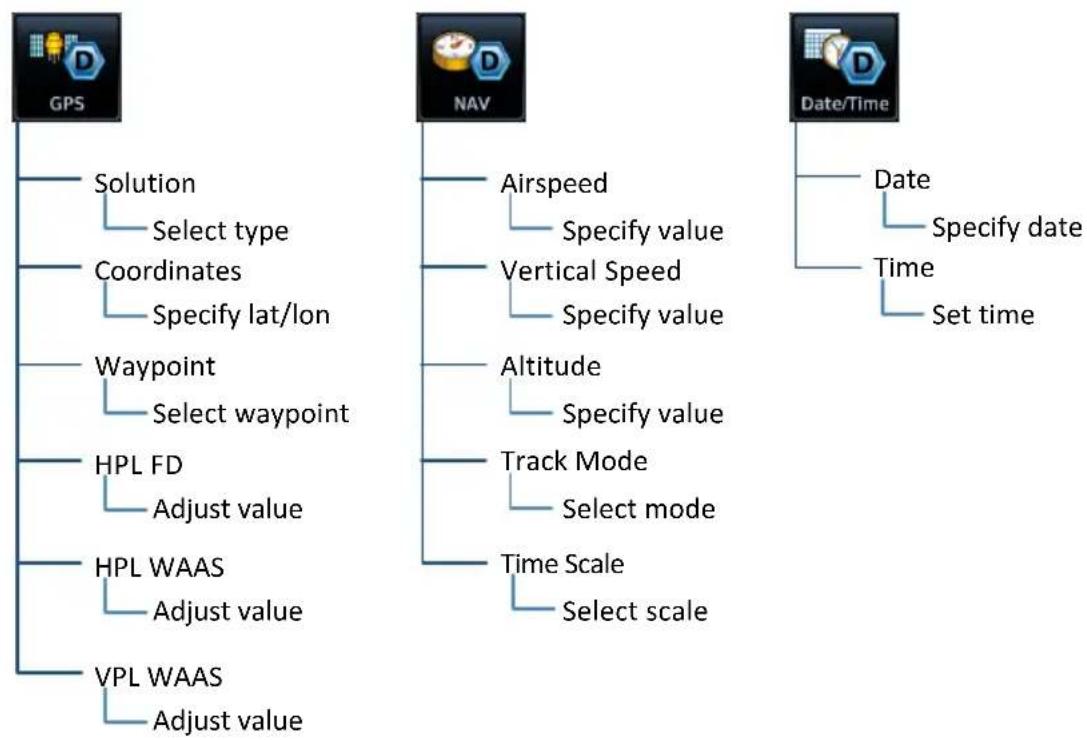
flowchart
graph TD
    A["GPS"] --> B["Solution"]
    A --> C["Coordinates"]
    A --> D["Waypoint"]
    A --> E["HPL FD"]
    A --> F["HPL WAAS"]
    A --> G["VPL WAAS"]
    H["NAV"] --> I["Airspeed"]
    H --> J["Vertical Speed"]
    H --> K["Altitude"]
    H --> L["Track Mode"]
    H --> M["Time Scale"]
    H --> N["Select scale"]
    O["Date/Time"] --> P["Date"]
    O --> Q["Time"]
    O --> R["Set time"]
    B --> S["Select type"]
    C --> T["Specify lat/lon"]
    D --> U["Select waypoint"]
    E --> V["Adjust value"]
    F --> W["Adjust value"]
    G --> X["Adjust value"]
Position Error Values
You may adjust position error values to reflect errors induced by naturally occurring conditions. These values are not normally adjusted for most demo mode operations. Values include:
• Horizontal protection levels for fault detection and SBAS
• Vertical protection levels for SBAS
11 Glossary
A
ACT Altitude Compensated Tilt
ADAHRS Air Data/Attitude & Heading Reference System
ADC Air Data Computer
ADF Automatic Direction Finder
ADIZ Air Defense Identification Zone
ADS-B Automatic Dependent Surveillance Broadcast
AFM Aircraft Flight Manual
AFMS Aircraft Flight Manual Supplement
AGL Above Ground Level
AHRS Attitude Heading Reference System
AIM Aeronautical Information Manual
AIRB Basic Airborne Application
AIRMET Airman's Meteorological Information
ALT Altitude Hold
AP Autopilot
APR Approach
APT Airport
ARINC Aeronautical Radio Incorporated
ARTCC Air Route Traffic Control Center
AR Approval Required
ASOS Automated Service Observing System
ATAS ADS-B Traffic Advisory System
ATC Air Traffic Control
ATIS Automatic Terminal Information Service
ATK Along Track
AWOS Automated Weather Observing Station
B
BRG Bearing
C
CDI Course Deviation Indicator
CDU Control and Display Unit
CNXT Connext
CRS Course
CTAF Common Traffic Advisory Frequency
CUM Cumulative
D
DALT Density Altitude
DB Database
DEST Destination
DFLT Default
DG Directional Gyro
DIS Distance
DME Distance Measuring Equipment
DPRT Departure
DTK Desired Track
E
EDM Emergency Descent Mode
EDR Excessive Descent Rate
EFC Expected Further Clearance
EGNOS European Geostationary Navigation Overlay Service
ENR En Route
ESA En Route Safe Altitude
ESP Electronic Stability and Protection
ETA Estimated Time of Arrival
ETE Estimated Time En Route
F
FAA Federal Aviation Administration
FAF Final Approach Fix
FCC Federal Communication Commission
FDC Flight Data Center
FIS-B Flight Information Services Broadcast
FLTA Forward Looking Terrain Avoidance
FMS Flight Management System
FPL Flight Plan
FREQ Frequency
FSS Flight Service Station
G
GAGAN GPS-aided GEO Augmented Navigation
GCS Ground Clutter Suppression
GDC Garmin Air Data Computer
GDL Garmin Data Link
GDU Garmin Display Unit
GFC Garmin Flight Controller
GMA Garmin Marker Beacon Audio
GMU Garmin Magnetometer Unit
GP Glidepath
GPS Global Positioning System
GPSS Global Positioning System Steering
GRS Garmin Reference System
GS Glideslope
GSL Geometric Sea Level
GSU Garmin Sensing Unit
GTP Garmin Temperature Probe
GTX Garmin Transponder
H
HDG Heading
HOT Hazardous Obstacle Transmission
HPL Horizontal Protection Level
HSDB High Speed Data Bus
HSI Horizontal Situation Indicator
HTAWS Helicopter Terrain Awareness and Warning System
|
IAF Initial Approach Fix
IAS Indicated Airspeed
IAT Induction Air Temperature
IFR Instrument Flight Rules
ILI Imminent Line Impact
ILS Instrument Landing System
INT Intersection
IOI Imminent Obstacle Impact
ISA International Standard Atmosphere
ITI Imminent Terrain Impact
K
KIAS Knots Indicated Airspeed
L
LCD Liquid Crystal Display
LDI Lateral Deviation Indicator
LOA Letter of Authorization
LOC Localizer
LOI Loss of Integrity
LPV Localizer Performance with Vertical Guidance
LRU Line Replaceable Unit
M
MAG VAR Magnetic Variation
MAP Missed Approach Point
MAHP Missed Approach Holding Point
MDA Minimum Descent Altitude
METAR Meteorological Terminal Aviation Routine Weather Report
MGRS Military Grid Reference System
MOA Military Operations Area
MOT Mark on Target
MSA Minimum Safe Altitude
MSAS MTSAT Satellite Augmentation System
MSG Message
MSL Mean Sea Level
N
NAV Navigation
NAVAID Navigation Aid
NCR Negative Climb Rate
NDB Non-Directional Beacon
NEXRAD Next-Generation Radar
0
OAT Outside Air Temperature
OBS Omni Bearing Selector
OCN Oceanic
P
PCL Pilot Controlled Lighting
PDA Premature Descent Alert
PVT Position, Velocity, and Time
R
RA Resolution Advisory RAIM Receiver Autonomous Integrity Monitoring RF Radius to Fix RLC Reduced Line Clearance RNAV Area Navigation RNP Required Navigation Performance ROC Reduced Required Obstacle Clearance RRC Remote Radio Control RTC Reduced Required Terrain Clearance
S
SAR Search and Rescue SAT Static Air Temperature SBAS Satellite Based Augmentation System SBS Surveillance and Broadcast Services SD Secure Digital SIGMET Significant Meteorological Information SSID Service Set Identifier STAR Standard Terminal Arrival
STBY Standby SUA Special Use Airspace SURF Surface Situation Awareness SUSP Suspend SVID Satellite-Vehicle Identification
T
T True
TA Traffic Advisory
TACAN Tactical Air Navigation System
TAF Terminal Aerodrome Forecast
TAS
Traffic Advisory System
True Airspeed
TAT Total Air Temperature
TAWS Terrain Awareness and Warning System
TCA Terminal Control Area
TCAD Traffic Alert and Collision Avoidance Devices
TCAS Traffic Alert and Collision Avoidance System
TCH Threshold Crossing Height
TERM Terminal
TFR Temporary Flight Restriction
TIS Traffic Information Service
TMA Terminal Maneuvering Area
TRK Track
TRSA Terminal Radar Service Area
TSAA Traffic Situational Awareness with Alerting
TSO
Technical Standard Order
U
UPS Universal Polar Stereographic Grid
USR
User
UTC Universal Time Coordinated
UTM Universal Transverse Mercator
V
VCALC Vertical Calculator
VDI Vertical Deviation Indicator
VFR Visual Flight Rules
VHF Very High Frequency
VLOC VOR/Localizer
VNAV Vertical Navigation
VOR Very High Frequency Omnidirectional Range
VORTAC Very High Frequency Omnidirectional Range Station and Tactical Air Navigation
VPL Vertical Protection Level
VRP Visual Reporting Point
VS Vertical Speed
VSI Vertical Speed Indicator
W
WAAS Wide Area Augmentation System
WGS84 World Geodetic System 1984
WPT Waypoint
WX Weather
X
XPDR Transponder
XTK Cross Track
12 Regulatory Information
COMPLIANCE....12-2
SOFTWARE LICENSE AGREEMENT 12-3
Compliance
FCC Compliance Statement
This device complies with Part 15 of the FCC limits for Class B digital devices. This equipment generates, uses, and can radiate radio frequency energy and, if not installed and used in accordance with the instructions, may cause harmful interference to radio communications. Furthermore, there is no guarantee that interference will not occur in a particular installation.
If this equipment does cause harmful interference, the user is encouraged to try to correct the interference by relocating the equipment or connecting the equipment to a different circuit than the affected equipment. Consult an authorized dealer or other qualified avionics technician for additional help if these remedies do not correct the problem.
Operation of this device is subject to the following conditions: (1) This device may not cause harmful interference, and (2) this device must accept any interference received, including interference that may cause undesired operation.
AC 90-100A Statement of Compliance
The Garmin navigational unit meets the performance and functional requirements of FAA Advisory Circular (AC) 90-100A, U.S. Terminal and En Route Area Navigation (RNAV) Operations.
Software License Agreement
BY USING THE DEVICE, COMPONENT OR SYSTEM MANUFACTURED OR SOLD BY GARMIN ("THE GARMIN PRODUCT"), YOU AGREE TO BE BOUND BY THE TERMS AND CONDITIONS OF THE FOLLOWING SOFTWARE LICENSE AGREEMENT. PLEASE READ THIS AGREEMENT CAREFULLY. Garmin Ltd. and its subsidiaries ("Garmin") grants you a limited license to use the software embedded in the Garmin Product (the "Software") in binary executable form in the normal operation of the Garmin Product. Title, ownership rights, and intellectual property rights in and to the Software remain with Garmin and/or its third-party providers. You acknowledge that the Software is the property of Garmin and/or its third-party providers and is protected under the United States of America copyright laws and international copyright treaties. You further acknowledge that the structure, organization, and code of the Software are valuable trade secrets of Garmin and/or its third-party providers and that the Software in source code form remains a valuable trade secret of Garmin and/or its third-party providers. You agree not to reproduce, decompile, disassemble, modify, reverse assemble, reverse engineer, or reduce to human readable form the Software or any part thereof or create any derivative works based on the Software. You agree not to export or re-export the Software to any country in violation of the export control laws of the United States of America.
INTENTIONALLY LEFT BLANK
GARMIN®
- SOFTWARE VERSION
- INFORMATION & SUPPORT
- Pilot Interface ....1-5
- Compatible Equipment 1-20
- GET STARTED 2-1
- Power Up 2-2
- Databases 2-7
- Connectivity 2-22
- COM 2-26
- Table of Contents
- Pilot Settings 2-68
- Status Indications 2-85
- Logs 2-96
- NAVIGATION 3-1
- PLANNING 4-1
- HAZARD AWARENESS 5-1
- Terrain Awareness 5-97
- ABNORMAL OPERATIONS 6-1
- Emergency Modes at a Glance 6-2
- Smart Glide 6-4
- Emergency Descent 6-28
- SERVICES 7-1
- SiriusXM Audio Entertainment 7-3
- Connext Services 7-9
- MESSAGES 8-1
- Advisory Messages 8-2
- QUALIFICATION 9-1
- PRACTICE 10-1
- WARNING
- CAUTION
- NOTE
- Record of Revision
- Available for Download
- Electronic Pilot's Guide
- Upgrade Supplement
- Layout
- Product Descriptions
- GTN 650Xi Series
- GTN 750Xi Series
- Feature Depictions
- Special Notations
- Insets
- System at a Glance
- Overview
- Unit Configurations
- Apps & Features
- Pilot Interface
- Bezel
- Bezel
- SD Card Slot
- Home Key
- Direct To Key
- Volume/Squelch Knob
- Inner & Outer Knobs
- Photocell
- Home Key Shortcuts
- SD Card Slot
- FEATURE LIMITATIONS
- INSERT AN SD CARD
- EJECT AN SD CARD
- For Mac Users
- Touchscreen
- Gestures
- Keys
- COMMON COMMANDS
- Zoom Control & Scale
- Directional Keys
- FUNCTION KEYS
- APP ICONS
- Menus
- SLIDE OVER MENUS
- LISTS
- Tabs
- Keyboards
- Control Knobs
- Dual Concentric Knob
- Volume/Squelch Knob
- Page Navigation Labels
- Knob Function Indicators
- Map Active Flight Plan Active
- Home Page Active
- Dual Concentric Knob Shortcuts GTN 650Xi/750Xi
- COM Standby Frequency Active
- Com Freq / Psh Nav
- Waypoint Identifier Keypad Active
- Wpt Ident / Psh Enter
- Numeric Keypad Active
- Num Entry / Psh Enter
- Direct To Window Active
- Edit Wpt / Psh Activate
- Screen Captures
- FEATURE REQUIREMENTS
- Screen Capture Successful
- Screen Capture Failed
- Color Conventions
- Red
- Yellow
- Green
- White
- Magenta
- Cyan
- Gray
- Blue
- Compatible Equipment
- Line Replaceable Units
- Get Started
- Power Up
- WI-FI SETUP ACCESS
- FUEL SETUP ACCESS
- Remote Database Confirmation
- Preset Fuel Quantities
- Fuel on Board
- Fuel Flow
- FUEL CAPACITY ENTRY KEYS
- Set Full/Tabs
- Full
- FUEL CAPACITY UNITS
- From the Home page:
- Instrument Panel Self-Test
- Databases
- Aviation Database Errors
- Database Effective Cycles
- DATABASE EFFECTIVE STATUS
- Overwriting SD card database files
- Database Conflicts
- DATABASE MISMATCH
- MISSING DATABASE INFORMATION
- Active and Standby Databases
- Active Databases Standby Databases
- Database Info
- STANDBY DATABASE LIST
- DATABASE NOT FOUND
- Manual Updates
- DATABASE SOURCE INDICATION
- SELECT ALL DATABASES
- Dual GTN Xi and GTN Xi/GDU TXi Installations 1
- SHOW ALL DATABASES
- ERROR INFORMATION
- SELECT REGION
- To specify a database region:
- Automatic Updates
- Automatic updates occur when:
- INSTALL OR UPDATE A DATABASE USING AN SD CARD
- Database Concierge
- Database Concierge Transfer Function
- TRANSFER A DATABASE USING DATABASE CONCIERGE
- SKIP TRANSFER
- Database SYNC
- WHERE TO FIND IT
- Database SYNC Transfer Function
- Dual GTN Xi Installations
- Chart Streaming
- Chart Streaming Function
- Connectivity
- Connext Setup
- Connext Features
- Bluetooth Setup
- Bluetooth Wireless Features
- BLUETOOTH NAME
- Managing Paired Devices
- AUTO RECONNECT
- REMOVE
- CONNECTION STATUS
- Importing a Flight Plan
- Wi-Fi Setup
- WI-FI INFO KEY STATUS ANNUNCIATIONS
- CONNECT TO WI-FI
- COM
- COM Standby Control Panel
- From the COM Standby control panel you can:
- COM Volume Controls
- Open Squelch
- Volume/Squelch Knob Adjustments
- COM Radio Setup
- From here you can:
- Set COM Channel Spacing
- Revert Knob Function to Radio Control
- Page Navigation COM Radio
- Access Remote Unit Radio Functions
- Local
- Local & Remote
- Enable Reverse Frequency Look-up
- When frequency look-up is active, COM displays:
- Adjust Sidetone Volume Offset
- LINK TO COM VOLUME
- Tuning & Monitoring
- COM STATUS INDICATIONS
- Direct Tuning
- DATA ENTRY KEYS
- FREQUENCY AUTOFILL
- Simplified Frequency Entry
- KNOB TUNING
- Transfer Frequency to Active (Flip-Flop)
- ACTIVE FREQUENCY WINDOW
- XFER KEY
- Frequency Flip-Flop via Control Knob
- Hold for Flip-Flop
- Frequency Autofill & Transfer
- Remote Radio Control
- Remote Radio Control Knob Access
- Direct Tuning from the Radios Page:
- LOAD FREQUENCY OPTIONS
- Monitor Mode
- Frequency Selection
- Search Tabs
- TAB ENTRIES
- MULTIPLE FREQUENCIES
- Remote Frequency Selection
- Emergency Frequency
- Remote COM Lock
- Create User Frequencies
- ADD A USER FREQUENCY
- EDIT USER FREQUENCY
- COM Alert
- Stuck Microphone
- NAV
- Frequency Tuning & Selection
- STANDBY NAV FREQUENCY ENTRY
- Navigation frequencies include:
- IDENT
- Volume Knob Adjustments
- NAV Alert
- Audio Panel
- Audio Panel Controls
- PLAYBACK CONTROLS
- Tap Playback Controls to:
- CABIN SPEAKER CONTROL AND VOLUME
- HIGH SENSE
- Mic Setup
- PASSENGER ADDRESS
- SPLIT MODE
- Active:
- Inactive:
- 3D Audio
- MARKER Audio
- Intercom
- Intercom Modes
- Intercom Setup
- VOLUME AND SQUELCH ADJUSTMENTS
- Music Setup
- Telephone Setup
- Tap Telephone to set:
- Bluetooth Audio
- Tap Bluetooth to set:
- Telligence Voice Command
- Voice Command Setup
- VOICE COMMAND HISTORY
- Audio Panel Alert
- XPDR
- XPDR Control Panel
- The XPDR key becomes available when you:
- XPDR Setup
- Enable ADS-B Out Transmissions
- Assign a Flight ID
- XPDR Modes
- MODE OPTIONS
- Standby
- On
- Altitude Reporting
- Squawk Code Keys
- VFR
- XPDR Key
- TRANSPONDER STATUS INDICATIONS
- IDENT Standby Mode
- IDENT with New Squawk Code Altitude Reporting Mode
- XPDR Alert
- ADS-B Altitude Reporting
- ADS-B Control Panel
- GDL 88 Features
- ADS-B Key
- OR
- Enable Anonymous Mode
- GDL 88 Alert
- Pilot Settings
- Setup
- Alerts
- Audio
- Units
- Backlight
- User Fields
- Page Shortcuts
- Flight Timers
- CDI Scale
- Auto Setting Annunciation Manual Setting Annunciation
- Aircraft is within 31 nm of the destination airport (i.e., terminal area).
- Horizontal Alarm Limits
- ILS CDI Capture
- Auto Switch Manual Selection
- Startup Page
- Page Options:
- Keyboard Type
- Nearest Airport Runway Criteria
- RUNWAY SURFACE
- Runway Surface Options
- MINIMUM RUNWAY LENGTH
- INCLUDE USER AIRPORTS
- Clocks & Timers
- Timers
- Clock/Generic Timer Trip/Departure Timers
- Controls:
- Clock
- RESTORE DEFAULTS
- Alerts Settings
- Arrival Alerts
- ENABLE AN ARRIVAL ALERT
- Airspace Alerts
- Airspace Alert Options
- Unit Selections
- SPECIFY UNIT TYPE
- User Selected NAV Angle
- Magnetic External
- True User
- Position Formats
- REGIONAL POSITION FORMATS
- Click Volume
- Click Volume Control
- HTAWS Voice Alert Options
- Voice Callout Availability
- Display Brightness Control
- Automatic Brightness Control
- Manual Brightness Control
- Scheduled Messages
- CREATE A REMINDER MESSAGE
- Message Types
- Modifying Scheduled Messages
- EDIT MESSAGE
- RESET TIMER
- DELETE MESSAGE
- Crossfill
- Crossfill Features
- WAYPOINT IDENTIFIERS
- GTN to GTN Data
- Alerts:
- External Sensors:
- Flight Plan Catalog
- System Setup:
- User waypoints
- Get Started
- GTN to GNS Data
- GTN to GNS GNS to GTN
- Status Indications
- Alert Types
- WARNINGS & CAUTIONS
- FUNCTION & MODE ADVISORIES
- Alert Annunciations
- ANNUNCIATION LOCATION
- Pop-up Alerts
- Pop-up Alert Priority
- Aural Alerts
- MUTE ALERT
- System Status
- SYSTEM INFO CONTROLS
- GPS Status
- SKY VIEW DISPLAY
- SIGNAL STRENGTH INDICATIONS
- Satellite SVIDs
- POSITION ACCURACY FIELDS
- LABEL POSITION DATA
- Circle of Uncertainty
- SBAS Providers
- GPS Status Annunciations
- GPS Alerts
- LRU Status
- Logs
- Flight Data Log Functions
- WAAS Diagnostic Log Functions
- FILE NAMING CONVENTIONS
- log\_YYMMDD\_HHMMSS\_WPT.csv
- Data Logging at a Glance
- If Flight Stream is present in GDU TXi:
- If Flight Stream is present in GTN Xi:
- If an SD card is present in GTN Xi:
- What happens if there's a power interruption?
- Export to an SD Card
- What if I forget to insert my SD card before flight?
- TRANSFER SD CARD DATA TO YOUR ONLINE LOGBOOK
- To create a logbook:
- To upload flight logs to your logbook:
- Streaming to Garmin Pilot
- What happens if I forget to bring my tablet on the flight?
- Navigation
- NAVIGATION APPS & FUNCTIONS
- Map
- Charts
- Waypoint Info
- Nearest
- Flight Plan
- Procedures
- Direct To
- Default NAV
- FEATURE LABELS
- TRAFFIC UNITS
- LAND AND WATER DEPICTIONS
- DATA DRAWING ORDER
- Map Setup
- Shared Map Settings
- Map Display Orientation
- North Up Track Up Heading Up
- Ownership Icon Position & Orientation
- North Up Above
- Visual Approach
- Auto Zoom
- Local Auto Zoom (Rotorcraft Only)
- Track Vector
- Altitude Constraints
- Glide Range Ring
- FIXED WING AIRCRAFT ONLY
- OPTIONAL COMPONENTS
- Glide Range Ring Options
- Best Glide Airport Indicator
- "No Wind Data" Indicator
- NEAREST AIRPORT GLIDE INDICATIONS
- NAV Range Ring
- Fuel Range Ring
- TOPO Scale
- Chart Color Scheme
- Selected Altitude Range Arc
- Aviation Selections
- Aviation Menu
- AVIATION DATA SYMBOLS
- SafeTaxi
- SafeTaxi Features
- SAFETAXI DATA SYMBOLS
- HOT SPOTS
- CONSTRUCTION SPOTS
- Airspace Selections
- Airspace Menu
- Smart Airspace
- Land Selections
- Land Menu
- LAND DATA SYMBOLS
- Traffic & Weather Selections
- TRAFFIC
- WEATHER
- Map Interactions
- Basic Interactions
- PAN & ZOOM
- OBJECT SELECTION
- MAP POINTER
- MAP INFO
- DATA FIELDS CONTROLS
- STACKED OBJECTS
- AIRSPACE INFO
- Graphical Flight Plan Editing
- TEMPORARY FLIGHT PLAN BANNER
- ADD WAYPOINT TO AN EXISTING LEG
- REMOVE WAYPOINT FROM FLIGHT PLAN
- CREATE LEGS WITHOUT AN EXISTING FLIGHT PLAN
- Graphical Flight Plan Mode
- Map Overlays
- Overlay Selections
- Overlay Controls
- TOPO
- TERRAIN
- NEXRAD
- STORMSCOPE
- AIRWAYS
- RADAR
- Overlay Status Icons
- USER FIELD TYPES
- Data Function Page
- Data Tab Options:
- Function Tab Options:
- Page Tab Options:
- TOPO SCALE & USER FIELDS
- TURN OFF USER FIELDS
- Default User Fields
- ADDITIONAL USER FIELDS
- Map Detail
- CHART STATUS
- Chart Setup
- Chart Information 1
- Invert Colors
- Chart Selection
- CHART TYPES
- Approach
- Arrival
- Departure
- Information
- AUTOMATIC CHART SELECTION
- Aircraft Position Icon
- POSITION UNAVAILABLE INDICATION
- OFF SCALE AREA
- Waypoints
- Waypoint Information
- Common Page Features
- Data Fields Waypoint Identifier
- MAP PREVIEW WINDOW
- Waypoint Specific Page Features
- Airport
- Intersection
- Very High Frequency Omni-directional Range
- Visual Reporting Point
- Non-Directional Beacon
- User Waypoint
- Waypoint Selection
- Waypoint Autofill
- FastFind Predictive Waypoint Entry
- FastFind & Flight Plan
- RECENT
- USER
- SEARCH BY NAME/CITY
- Search By Name
- Search By City
- Create User Waypoints
- MAP POINTER/CREATE WAYPOINT KEY
- USER WAYPOINT IDENTIFIER
- User Airport
- Define Waypoint Criteria
- COMMENT FORMAT
- LAT/LON Radial/Distance
- Radial/Radial
- POSITION TYPE
- Radial/Radial Radial/Distance LAT/LON
- MARK WAYPOINTS
- Create a User Waypoint
- OPEN CREATE USER WAYPOINT PAGE
- From Map:
- ASSIGN POSITION VALUES
- MODIFY DEFAULT SETTINGS
- Edit an Existing User Waypoint
- ACCESS USER WAYPOINT EDIT OPTIONS
- From the dedicated information page:
- From the Nearest page:
- From the Active FPL page:
- MODIFY POSITION VALUES
- Delete User Waypoints
- DELETE ALL USER WAYPOINTS
- Import User Waypoints
- FUNCTIONAL LIMITATIONS
- CREATE USER WAYPOINT FILE
- ABCD
- User Waypoint File Considerations
- Nearest Airport
- Nearest Intersection
- Nearest Very High Frequency Omni-directional Range
- Nearest Visual Reporting Point
- Nearest Non-Directional Beacon
- Nearest User Waypoint
- Nearest Airspace
- Nearest Air Route Traffic Control Center
- Nearest Flight Service Station
- Nearest Weather Frequency
- UPDATE INTERVALS
- Active Flight Plan
- ACTIVE LEG STATUS INDICATIONS
- Create a Flight Plan
- CREATE FROM THE ACTIVE FLIGHT PLAN PAGE
- CREATE FROM MAP
- CREATE FROM THE FLIGHT PLAN CATALOG
- Airway Options
- Collapse All Airways
- Sort Airways
- En Route Vertical Navigation
- VNAV Functions
- Define a VNAV Profile
- ENABLE VNAV GUIDANCE
- Disabling vertical navigation:
- ALTITUDE CONSTRAINT INDICATIONS
- Altitude Constraint Data Priority
- INVALID ALTITUDE CONSTRAINTS
- ALTITUDE CONSTRAINT OPTIONS
- Designate a waypoint altitude for use with vertical guidance:
- Enter or modify an altitude constraint:
- Delete an altitude constraint:
- Return a modified altitude constraint to its original database value:
- VNAV Direct To
- ACTIVATE VNAV DIRECT TO
- Transition to Approach
- Temperature Compensated Altitude
- SETTING TEMPERATURE COMPENSATED ALTITUDE
- ACTIVATE TEMPERATURE COMPENSATED ALTITUDE
- OBS
- SUSPEND/UNSUSPEND
- SUSP
- UNSUSP
- Dead Reckoning
- Points About Dead Reckoning
- When dead reckoning mode is active:
- Parallel Track
- ACTIVATE A PARALLEL TRACK
- Invert Flight Plan
- INVERT THE ACTIVE FLIGHT PLAN
- Edit Data Fields
- CHANGE DATA FIELD TYPE
- Catalog Route Options
- Route Options
- ACTIVATE
- INVERT & ACTIVATE
- PREVIEW
- EDIT
- COPY
- DELETE A FLIGHT PLAN
- From the FPL menu:
- From the catalog:
- DELETE ALL CATALOGED FLIGHT PLANS
- Flight Plan Waypoint Options
- Options Menu
- Import a Flight Plan
- Import Options
- IMPORT USING CONNEXT
- IMPORT FROM A DATACARD
- From the Flight Plan Catalog:
- Potential Import Errors
- Full catalog.
- Flight plan contains errors.
- Flight plan exceeds the waypoint limit.
- Along Track Offsets
- CREATE AN ATK
- From the active flight plan:
- CREATE AN ATK FOR AN ALTITUDE CONSTRAINT
- MODIFY AN ATK OFFSET
- User Holds
- Hold at Waypoint Options
- HOLD PREVIEW
- CREATE & ACTIVATE A HOLD
- Search and Rescue Patterns
- SAR Pattern Options
- SAR PATTERN PREVIEW
- SAR PATTERN TYPES
- CREATE & ACTIVATE A SEARCH AND RESCUE PATTERN
- SAR Flight Plan Options
- REMOVE A SEARCH AND RESCUE PATTERN
- Flight Plan Map Overlays
- Leg Status Indications
- Along Track Offset Indications
- Altitude Constraint Labels
- User Airport Icon
- CDI
- GPS Receiver VLOC Receiver
- If the unit is not configured for a CDI key:
- GPS Nav Status Bar
- No Flight Plan Exists
- Active Route Display
- Direct To Basics
- Direct To is useful for quickly navigating to:
- Direct To Search Tabs
- WAYPOINT
- FPL & NRST APT
- Direct To Activation
- ACTIVE FIX INDICATIONS
- Map User Field
- Active Flight Plan Indication
- Navigating Direct To
- DIRECT TO A NEW WAYPOINT
- DIRECT TO A FLIGHT PLAN WAYPOINT
- Flight Plan Waypoints
- DIRECT TO THE NEAREST AIRPORT
- DIRECT TO A MAP WAYPOINT
- MAPWPT
- DIRECT TO AN OFF-ROUTE COURSE
- Direct To & Procedure Fixes
- Remove a Direct Course
- LOAD A PROCEDURE
- COMMON PAGE CONTROLS
- Flight Procedure Basics
- When adding procedures to a flight plan:
- Roll Steering
- TO/FROM LEGS ON CDI
- TO Legs FROM Legs
- Localizer or VOR-based Approaches
- GPS Flight Phase Annunciations
- Departures
- Loading a Departure into Flight Plan
- PAGE SPECIFIC CONTROLS
- SELECT A DEPARTURE
- To change the departure:
- Flight Plan Departure Options
- Departure Options
- Arrivals
- Loading an Arrival into Flight Plan
- SELECT AN ARRIVAL
- To change the arrival:
- Flight Plan Arrival Options
- Approaches
- Loading an Approach into Flight Plan
- SELECT AN APPROACH
- To change the approach:
- SBAS APPROACHES
- Channel ID Key
- SUSPENDED APPROACH PROCEDURE ANNUNCIATION
- PROCEDURE TURNS
- Roll Steering & Procedure Turns
- Flight Plan Approach Options
- Approach Options
- Missed Approach
- BEFORE MISSED APPROACH POINT
- CROSSING MISSED APPROACH POINT
- AFTER MISSED APPROACH POINT
- Approach Hold
- Hold Entry Leg Hold Leg Hold Exit Leg
- APPROACH HOLDS WITHOUT AN EXIT LEG
- FLIGHT PLAN APPROACH HOLD OPTIONS
- Hold Options
- ACTIVATE HOLD
- REMOVE HOLDING PATTERN
- EXIT HOLDING PATTERN
- NON-REQUIRED HOLDING PATTERNS
- DME Arc
- DME Arc Approaches
- RF Legs
- AC 90-101A - RF Legs
- Vectors to Final
- ILS Approach
- VOR+V Approaches
- RNAV Approaches
- Always fly to the published minimums for:
- LNAV APPROACH
- LNAV+V APPROACH
- LPV APPROACH
- Within 31 nm of destination:
- Approaching initial approach fix:
- Approaching final approach fix:
- nm from final approach fix:
- seconds before final approach fix:
- When crossing the final approach fix:
- After the aircraft passes final approach fix:
- Approaching missed approach point:
- Crossing missed approach point:
- Prepare aircraft for missed approach operation:
- LP APPROACH
- Points About LP Approaches
- Within 30 nm of destination:
- Points About Visual Approaches
- LOAD A VISUAL APPROACH FROM MAP
- LOAD A VISUAL APPROACH FROM PROCEDURES
- Autopilot Outputs
- ENABLE AUTOPILOT OUTPUTS
- Planning
- PLANNING APPS & FUNCTIONS
- VCALC
- Trip Planning
- RAIM Prediction
- Checklists
- Fuel Planning
- DALT/TAS/Winds
- Define a VCALC Profile
- STATUS & VS REQUIRED INDICATIONS
- Status
- VS Required
- VCALC Setup
- Restore Defaults Display Messages
- Trip Planning Modes
- Point-to-Point Mode Flight Plan Mode
- COMPLETED LEG INDICATION
- Trip Statistics
- Trip statistics include:
- DESTINATION SUNRISE/SUNSET TIMES
- ETA CALCULATIONS
- COMPUTE TRIP STATISTICS
- Fuel Planning Modes
- For Planning Purposes Only
- Fuel Statistics
- Fuels statistics include:
- COMPUTE FUEL STATISTICS
- DALT/TAS/Wind Calculator
- Edit Input Data
- DALT/TAS/Wind Statistics
- This information is for planning purposes only.
- Density Altitude Wind Data
- INVALID INPUT DATA INDICATION
- RAIM Features
- Calculate RAIM Status
- WAYPOINT SEARCH OPTIONS
- ARRIVAL DATE & TIME
- CHECK RAIM AVAILABILITY
- RAIM STATUS INDICATIONS
- Disclaimer
- View a Checklist
- CHECK BOXES
- LIST STATUS ANNUNCIATIONS
- COMPLETE A CHECKLIST
- Hazard Awareness
- Weather Awareness
- Datalink Weather
- WX Info Banner
- Banner Information
- WX Display Orientation
- WX Display/Map Settings
- Map Tab Aviation Tab Land Tab
- Settings:
- Datalink Weather Products
- Airport Info
- WX Pop-up
- Raw Text Reports
- DATALINK WEATHER PRODUCTS LIST
- Product Age
- TIMESTAMP COLOR DEFINITIONS
- SiriusXM WX Product Age
- Connext WX Product Age
- Product Legends
- Altitude Adjustment Keys
- Airport Icons
- Precipitation
- CONUS NEXRAD Regional NEXRAD
- RADAR DATA ANIMATIONS
- CONNEXT PRECIP
- FIS-B NEXRAD
- Missing Data Indications
- Source Options:
- CONUS
- Regional
- Combined
- SIRIUSXM NEXRAD
- Composite (CONUS)
- Base
- Textual AIRMETs
- AVAILABLE WITH: SIRIUSXM | CONNEXT
- AIRMET TYPES
- Icing
- Turbulence
- IFR
- MTN OBSR
- Surface Winds
- Graphical AIRMETs
- AVAILABLE WITH: FIS-B
- Forecast Settings:
- Off Current (Auto) All Forecasts
- Hazard Awareness
- G-AIRMET FILTERS
- To enable graphical AIRMETs:
- AIREPs
- Cell Movements
- AVAILABLE WITH: SIRIUSXM
- Top Heights
- Center Weather Advisory
- City Forecast
- Forecast Period Options:
- Clouds
- CLOUD TOPS
- IR SATELLITE
- AVAILABLE WITH: CONNEXT
- County Warnings
- Cyclone
- Echo Tops
- Freezing Levels
- FIS-B Weather:
- ICING CATEGORIES
- Lightning
- SiriusXM Weather:
- Connext Weather:
- METARs and TAFs
- AVAILABLE WITH: FIS-B | SIRIUSXM | CONNEXT
- METAR SYMBOLS
- Marginal VFR
- Low IFR
- Unknown
- PIREPs
- PIREP SYMBOLS
- SIGMETs
- Surface Analysis
- TFRS
- Winds Aloft
- FIS-B Winds & Temperatures Aloft:
- SiriusXM Weather
- Activate SiriusXM Services
- When SiriusXM weather services are not activated:
- COMPLETE SUBSCRIPTION ACTIVATION
- Troubleshooting the GDL 69/69A Datalink Receiver
- SiriusXM Weather Setup
- Map WX Overlays
- FIS-B Weather
- Data Transmission Limitations
- LINE OF SIGHT RECEPTION
- PER FAA TSO-C157B
- NOTAM 30-DAY LIMITATION
- FIS-B Product Status
- FIS-B WEATHER ENABLED
- FIS-B Weather Setup
- READING WINDS/TEMPS ALOFT REPORTS
- ALTITUDE (FT)
- FIS-B Ground Reception Status
- OPEN FIS-B RECEPTION STATUS PAGE
- Connext Weather
- Activate Connext Satellite Services
- To complete activation:
- Deactivate Connext Unit Registration
- From the GSR Status page:
- Connext Weather Setup
- Connext Data Requests
- DATA REQUEST CONTROLS
- Request Data
- Auto Request 10 MIN
- Auto Request
- 00:14 Remaining...
- Multiple Weather Requests
- Stormscope Features
- Stormscope Setup
- Stormscope Map Overlay
- Stormscope Modes & Symbols
- Cell Mode Strike Mode
- When to use:
- Strike Rate
- CLEAR STRIKES
- Views
- ARC VIEW
- 360° VIEW
- Stormscope Display Orientation
- Airborne Weather Radar
- Maximum Permissible Exposure Level, GWX 68
- RADAR UNITS
- DISPLAY ADJUSTMENTS
- TILT AND BEARING ADJUSTMENTS
- INTENSITY SCALE
- WARM-UP COUNTDOWN TIMER
- Weather Radar Setup
- ALTITUDE COMPENSATED TILT
- AVAILABLE WITH: GWX 70/75/80
- SECTOR SCAN
- STABILIZATION
- TURBULENCE DETECTION
- WATCH
- WEATHER MESSAGES
- Radar Modes
- TEST
- GROUND
- Radar Controls
- SHOW BEARING/TILT
- BEARING
- TILT
- Basic Antenna Tilt Setup
- Altitudes between 2,000 and 30,000 ft AGL:
- Altitudes above 29,000 ft:
- VERTICAL SCAN
- Vertical Scan with Stabilization
- HORIZONTAL SCAN
- GAIN
- Radar Alerts
- When a radar alert occurs:
- Traffic Awareness
- Available Traffic Sources
- Traffic Display
- GROUND STATION TRANSMITTER STATUS ICON
- TRAFFIC GROUPS
- OFF SCALE TRAFFIC ALERTS
- TRAFFIC OVERLAY STATUS ICON (MAP ONLY)
- Traffic Setup
- Map Traffic Overlay
- Traffic Test
- Altitude Filtering
- Traffic Interactions
- Selected Traffic Information
- Traffic Types
- TIS-A
- TIS-A Features
- TIS-A SETUP SELECTIONS
- TIS-A TRAFFIC SYMBOLS
- TCAD 9900B
- TCAD 9900B PAGE SELECTIONS
- TCAD 9900B MENU SELECTIONS
- SHIELD SETUP
- Set an approach shield:
- Set an En Route, Standard, or Terminal shield:
- Select a mode:
- TCAD 9900BX
- TCAD 9900BX SYMBOLS
- Ryan TCAD 9900BX with GDL 88
- Ryan TCAD Features
- TRAFFIC DISPLAY RANGE
- RYAN TCAD ALERT TYPES
- TCAD SETUP SELECTIONS
- TAS/TCAS I
- TAS/TCAS I Features
- TAS/TCAS I SETUP SELECTIONS
- TAS/TCAS I TRAFFIC SYMBOLS
- TCAS II
- TCAS II Features
- TCAS II ALERTS
- Warning Banner
- RA X.X ± XX OR
- Caution Banner
- TA X.X ± XX OR
- TCAS II TRAFFIC SYMBOLS
- OT
- PA
- TA
- Off-scale TA
- RA
- Off-scale RA
- TCAS II WITH ADS-B
- ADS-B
- ADS-B Features
- ADS-B SETUP SELECTIONS
- ADS-B TRAFFIC SYMBOLS
- ADS-B TRAFFIC APPLICATIONS
- Traffic Application Failures
- MOTION VECTORS
- ADS-B STATUS INDICATIONS
- ADS-B TRAFFIC INTERACTIONS
- Traffic Alerting
- Traffic Alert Types
- Alerting Parameters
- Alerting Parameter Considerations
- Terrain Awareness
- Terrain Configurations
- Available Terrain Modes
- GPS Altitude for Terrain
- GSL ALTITUDE & INDICATED ALTITUDE
- GSL Altitude Indicated Altitude
- Database Limitations
- Terrain Display
- AUTOMATIC ZOOM
- AUTOMATIC DATA REMOVAL
- Terrain Setup
- Map Terrain Overlays
- Terrain Proximity
- Terrain Proximity Features
- Terrain Elevation Depictions
- Obstacle Elevation Depictions
- POWER LINE OBSTACLES
- OBSTACLE GROUPS
- TERRAIN ALERTING
- TAWS-A
- TAWS-B
- Alerting Thresholds
- NER THRESHOLDS
- OVERRIDING FLAPS-BASED FIT ALERTING
- EXCESSIVE BELOW GLIDESLOPE/GLIDEPATH DEVIATION ALERT
- Terrain Alerting Features
- TERRAIN SYSTEM STATUS
- Alert Inhibit, TAWS & Terrain Alerting
- TAWS-A INHIBIT ANNUNCIATIONS
- TAWS-B Features
- TAWS-B Setup Selections
- TAWS-B Alerts
- Altitude VCO
- TAWS-B Not Available Alert
- TAWS-B Failure Alert
- TAWS-B SYSTEM STATUS
- TAWS-A Features
- TAWS-A Setup Selections
- INHIBIT
- AUTOMATIC INHIBIT
- TAWS-A Alerts
- ENABLE FLAP OVERRIDE
- INHIBITING GLIDESLOPE DEVIATION (GSD) ALERTS
- INHIBITING GPWS ALERTS (EDR, ECR, FIT, AND NCR)
- ALTITUDE VOICE CALL OUT (VCO)
- TAWS-A SYSTEM STATUS
- TAWS-A ABNORMAL OPERATIONS
- HTAWS/(H)Terrain Alerting
- HTAWS Setup Selections
- HTAWS Alerts
- FLTA Caution:
- FLTA Warning:
- HTAWS VOICE CALL OUT (VCO) AURAL ALERT
- HTAWS VCO SELECTION
- To select VCO choices:
- HTAWS NOT AVAILABLE ALERT
- HTAWS FAILURE ALERT
- HTAWS ALERT SUMMARY
- PILOT ACTIONS
- Abnormal Operations
- Emergency Modes at a Glance
- Smart Glide
- How it Works
- UPON ACTIVATION
- Dual GTN Xi Installations:
- Single GTN Xi Installations:
- Installations with GFC 500/600 Autopilot:
- Smart Glide Function
- Suitable airport within glide range:
- No suitable airport within glide range:
- DURING SMART GLIDE MODE
- Glide Destination Airport Criteria
- Smart Glide & Glide Range Ring
- Advisory Alert Caution Alert
- APPROACHING AIRPORT
- AIRPORT OUT OF RANGE
- Warning Alert
- MANEUVER AND LAND
- Flashing Alert Annunciations
- Enable Smart Glide Activation
- To enable or disable Smart Glide activation:
- Activate Smart Glide
- ACTIVATE SMART GLIDE VIA EXTERNAL SWITCH
- ACTIVATE SMART GLIDE USING THE DIRECT TO KEY
- Hold for Smart Glide Activation in 3
- ACTIVATE SMART GLIDE FROM THE EMERGENCY PAGE
- View Smart Glide Status Information
- Glide → KIPT Williamsport Rgnl Arrival AGL: 2740 FT
- LONGEST RUNWAY INFORMATION
- "Wind data not available" Indication
- Wind data not available
- BEST GLIDE SPEED INDICATION
- SMART GLIDE CONTROLS
- Emergency Smart Glide Page
- Tune Transponder
- View Smart Glide Information on Map
- Data removed during Smart Glide
- Data depicted during Smart Glide
- Select an Alternate Airport on Map
- Find Alternate Airport
- Deactivate Smart Glide
- Upon deactivation:
- Smart Glide Alerts
- When an alert occurs:
- System Failure Alerts
- Emergency Descent
- EDM Activation
- Manual Activation
- Automatic Activation
- Services
- SERVICES APPS & FUNCTIONS
- Phone
- SMS Text
- Music
- Position Reports
- Contacts
- SiriusXM Audio Entertainment
- SiriusXM Audio Activation
- OPEN GDL 69A STATUS PAGE
- Adjust Radio Volume
- Direct Channel Tuning
- SiriusXM Radio Options
- Browse Music Channels
- Assign Channel Presets
- Quick Tuning Options
- ASSIGN A CHANNEL PRESET
- SELECT A PRESET
- XM Data Link Failure
- Connext Services
- Phone Volume
- Volume controls are available only when Phone is:
- Phone Status Annunciations
- Suppress Visuals
- Off On
- On During APR/MAPR/TERM
- Suppression does not affect:
- In-Call Distribution
- Outgoing Calls
- MAKE A CALL
- DATA ENTRY
- Incoming Calls
- ACCEPT A CALL
- IGNORE A CALL
- MESSAGE ICONS & NOTATIONS
- TXing
- Sent
- New
- Send/Resend
- Open
- Failed
- Message Filtering & Setup Options
- Send a Text Message
- MESSAGE FAILED TO SEND
- To resend the message:
- Receiving Text Messages
- Received Message Options
- Position Reporting Status Annunciations
- GSR 56 Product Information Reporting:
- Counters & Timers
- Time Until Transmit Reports in Queue
- Position Reporting
- SPECIFY A REPORT PERIOD
- SEND A REPORT
- Create a Contact
- Find a Contact
- Contact Options
- DELETE A CONTACT
- Messages
- Advisory Messages
- Dual GTN Installations
- Message Key
- Airspace Advisories
- Database Advisories
- Datalink Advisories
- GPS/WAAS Advisories
- Navigation Advisories
- Points About Non-WGS84 Waypoints
- Pilot Specified Advisories
- Smart Glide Advisories
- System Hardware Advisories
- Audio Panel Advisories
- COM Radio Advisories
- ADVISORY CONDITION CORRECTIVE ACTION
- REMOTE KEY STUCK
- XPDR Advisories
- Terrain Advisories
- Traffic System Advisories
- VLOC/GS Advisories
- Waypoint Advisories
- Qualification
- Glove Qualification
- GLOVE SELECTION CONSIDERATIONS
- GLOVE QUALIFICATION STEPS
- GLOVE QUALIFICATION PROCEDURE
- Voice Command Qualification
- Qualification Procedure Requirements
- ACCEPTANCE CRITERIA
- VOICE COMMAND GUIDELINES
- ALTERNATE COMMANDS
- Practice
- Demo Mode
- Enable Demo Mode
- Demo Setup Options
- Demo Setup
- Advanced Settings
- Position Error Values
- Glossary
- A
- B
- C
- D
- E
- F
- G
- H
- |
- K
- L
- M
- N
- 0
- P
- R
- S
- T
- U
- V
- W
- X
- Regulatory Information
- Compliance
- FCC Compliance Statement
- AC 90-100A Statement of Compliance
- Software License Agreement
- GARMIN®
Brand : GARMIN
Model : GTN 625Xi
Category : Instrument de navigation aérienne