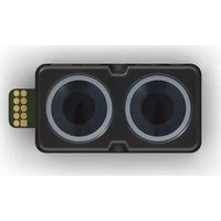
LIDAR-Lite v4 LED - Capteur lidar GARMIN - Free user manual and instructions
Find the device manual for free LIDAR-Lite v4 LED GARMIN in PDF.


| Product Type | LIDAR Distance Sensor |
| Brand | Garmin |
| Model | LIDAR-Lite v4 LED |
| Measurement Range | Up to 40 m (indoor) / 30 m (outdoor) |
| Accuracy | ±2.5 cm (typical) |
| Resolution | 1 cm |
| Dimensions (L x W x H) | 48 x 20 x 40 mm |
| Weight | 22 g |
| Supply Voltage | 5 V DC |
| Current Consumption | 105 mA (active), 70 mA (idle) |
| Interface | I2C (up to 400 kHz) and PWM (capture or output) |
| Laser Class | Class 1 (eye-safe) |
| Laser Wavelength | 905 nm |
| Update Rate | Up to 400 Hz (I2C), 100 Hz (PWM) |
| Operating Temperature | -10°C to +50°C |
| Mounting Holes | 4x M3 threaded holes |
| Field of View | ±12° (typical) |
| Compatible Logic Levels | 3.3 V or 5 V |
| Spare Parts Available | None (integrated unit) |
| Maintenance | Keep lens clean, avoid moisture |
| Safety Precautions | Do not stare into laser beam; Class 1 product |
Frequently Asked Questions - LIDAR-Lite v4 LED GARMIN
User questions about LIDAR-Lite v4 LED GARMIN
0 question about this device. Answer the ones you know or ask your own.
Ask a new question about this device
Download the instructions for your Capteur lidar in PDF format for free! Find your manual LIDAR-Lite v4 LED - GARMIN and take your electronic device back in hand. On this page are published all the documents necessary for the use of your device. LIDAR-Lite v4 LED by GARMIN.
USER MANUAL LIDAR-Lite v4 LED GARMIN
| Specification Measurement | |
| Unit dimensions (L × W × H)NOTE: Measurements do not include an attached connector. | 52.2 x 24 x 21.2 mm (2.1 x 0.9 x 0.8 in.) |
| Weight 14.6 g (0.5 oz.) | |
| Operating temperature -20 to 60°C (-4 to 140°F) | |
| Storage temperature -40 to 85°C (-40 to 185°F) | |
| Power (operating voltage) 4.75 to 5.25 Vdc | |
| Current consumption 2 mA idle | 85 mA during an acquisition |
| Input voltage (VIN) 3.3 V Max | |
| Range 5 cm (1.97 in.) to 10 m (32.8 ft.) | |
| Resolution 1 cm (0.4 in.) | |
| Beam divergence 4.77 degrees | |
| LED wavelength 940 nm | |
| Optical aperture 14.9 mm | |
| Update rate I2C: Greater than 200 Hz typicalANT: Up to 200 Hz to a 90% reflective target indoors at 2 m in normal operating mode | |
| Interface I2C or ANT | * Configurable for SPI with user applications |
| Measurement repeatabilityNOTE: As measured indoors to a 90% reflective target; 1 cm is equivalent to 1 standard deviation. Measurements were obtained using high accuracy mode. | ± 1 cm to 2 m± 2 cm to 4 m± 5 cm to 10 m |
Device Dimensions

| 1 | 52.17 mm (2.05 in.) |
| 2 | 44.98 mm (1.77 in.) |
| 3 | 10.6 mm (0.42 in.) |
| 4 | 24.03 mm (0.95 in.) |
| 5 | 1 mm (0.04 in.) |
| 6 | 18 mm (0.71 in.) |
| 7 | 21.35 mm (0.84 in.) |
| 8 | 21.2 mm (0.83 in.) |
Mounting Options
Cable tie: You can secure the device to your application using a 3.6 mm (0.14 in.) wide cable tie. You should route the cable tie through the channel in the center of the device.
Double-sided tape: You can secure the bottom of the device to your application using double-sided tape. For best results, you should select a tape that has a high-strength bond.
Labeling Requirements
The LIDAR-Lite v4 LED device is an FCC-certified transmitter. If you are integrating the device with another product, you must ensure the FCC ID is visible from the outside of your product. You are responsible for meeting any other labeling requirements imposed by the FCC rules and any rules related to the compliance of your end product.
Connections
LIDAR-Lite v4 LED Connection Diagram
The through-holes on the LIDAR-Lite v4 LED device are arranged in 2 rows of 5 holes each, with a 2 mm pitch between each connection.
NOTICE
The LIDAR-Lite v4 LED maximum signal level is 3.3 V. A signal greater than 3.3 V will damage the device.

| Pin Pin Name Function | V Max | ||
| 1 | VIN | 5 V Power | 5 V |
| 2 | GND | Ground | -- |
| 3 | I2C SDA | I2C Data | 3.3 V |
| Pin Pin Name Function V Max | |||
| 4 | I2C SCL I2C Clock | 3.3 V | |
| 5 | GPIOA General Purpose I/O 3.3 V | ||
| 6 | GPIOB General Purpose I/O 3.3 V | ||
| 7 | VRETURN nRF52840 | DBG 3.3 V | |
| 8 | nRESET nRF52840 | DBG 3.3 V | |
| 9 | SWCLK nRF52840 | DBG 3.3 V | |
| 10 | SWDIO nRF52840 | DBG 3.3 V | |
Operational Information
Technology
This device measures distance by calculating the time delay between the transmission of a near-infrared light and its reception after reflecting off of a target, using the known speed of light.
The LIDAR-Lite v4 LED contains an nRF52840 SoC from Nordic Semiconductor. This SoC pairs an ARM Cortex-M4 processor with 1 MB of flash memory and 256 KB of RAM. The included 2.4GHz multiprotocol radio and S340 SoftDevice support Ultra Low Power (ULP) wireless technologies, including ANT and Bluetooth® 5 LE.
The LIDAR-Lite v4 LED comes preloaded with an application that allows the developer to communicate with the device using several methods. An I2C interface allows the device to be connected to an external micro-controller, or it can be controlled and operated wirelessly using the ANT wireless protocol in accordance with the ANT Ranging Profile.
The LIDAR-Lite v4 LED also comes preloaded with a Bluetooth LE secure DFU bootloader, which enables wireless software updates using a Bluetooth LE capable device.
Theory of Operation
When the device takes a measurement, it first performs a receiver adjustment routine, correcting for changing ambient light levels and allowing maximum sensitivity.
The device sends a reference signal directly from the transmitter to the receiver. It stores the transmit signature, sets the time delay for "zero" distance, and recalculates this delay periodically after several measurements.
Next, the device initiates a measurement by performing a series of acquisitions. Each acquisition is a transmission of the main light signal while recording the return signal at the receiver. If there is a signal match, the result is stored in memory as a correlation record. The next acquisition is summed with the previous result. When an object at a certain distance reflects the light signal back to the device, these repeated acquisitions cause a peak to emerge, out of the noise, at the corresponding distance location in the correlation record.
The device integrates acquisitions until the signal peak in the correlation record reaches a maximum value. If the returned signal is not strong enough for this to occur, the device stops at a predetermined maximum acquisition count.
Signal strength is calculated from the magnitude of the signal record peak and a valid signal threshold is calculated from the noise floor. If the peak is above this threshold, the measurement is considered valid and the device will calculate the distance. If the peak is not above the threshold, it will report 1 cm. When beginning the next measurement, the device clears the signal record and starts the sequence again.
Interface
Initialization
When you turn on or reset the device, it performs a self-test sequence and initializes all registers with default values. After roughly 22 ms, you can take distance measurements using the
I2C interface, the mode control pin, or a wireless ANT connection.
I2C Interface
This device has a 2-wire, I2C-compatible serial interface. It can be connected to an I2C bus as a slave device, under the control of an I2C master device. It supports 400 kHz Fast Mode data transfer.
The I2C bus operates internally at 3.3 Vdc. Internal 13 kiloohm pull-up resistors ensure this functionality and allow for a simple connection to the I2C host.
The device has a 7-bit slave address with a default value of 0x62. The effective 8-bit I2C address is 0xC4 write and 0xC5 read. The device does not respond to a general call. Support is not provided for 10-bit addressing. The device auto-increments the register address with successive reads or writes within an I2C block transfer. This is commonly used to read the two bytes of a 16-bit value within one transfer. See Obtaining Measurements from the I2C Interface, page 2.
For a list of all available control registers, see Control Register List, page 5.
For more information about the I2C protocol, see I2C Protocol Information, page 4.
Obtaining Measurements from the I2C Interface
You can obtain measurement results from the I2C interface.
1 Write 0x04 to register 0x00.
2 Read register 0x01.
3 Repeat step 2 until bit 0 (LSB) goes low.
4 Read two bytes from 0x10 (low byte 0x10 then high byte 0x11) to obtain the 16-bit measured distance in centimeters.
Settings
You can configure the device with alternate parameters for the distance measurement algorithm. You can use this algorithm to customize performance by enabling configurations that allow speed, range, and sensitivity options. See the full control register list (Control Register List, page 5) for additional settings.
Configurable I2C Address
You can change the I2C address from its default to any 7-bit value. Before you can configure the secondary I2C address, you must first enable flash storage (0xEA). After you configure the secondary I2C address, the address persists if you turn off the device. You can use this process to run multiple devices on a single bus by enabling a device, changing its address, and then enabling the next device. Before you can change the I2C address, the I2C communications bus must read the UNIT_ID and write it back to the device in a single five-data-byte transaction with the new I2C address as the fifth byte. Software template functions for configuring the I2C address are available at https://github.com/garmin/.
Mode Control Pins
The mode control pins can be used to trigger distance measurements and check the status of the LIDAR-Lite v4 LED. These connections are not required. These pins can provide a simpler and faster method of controlling the device, and they are intended to be used in conjunction with the I2C interface. For more information, go to https://github.com/garmin/.
| Pin Description Functionality Details | |||
| GPIO A | TRIGGER LID | AR-Lite v4LEDmeasurementtrigger input | Toggle to start a distance measurement. The LIDAR-Lite v4 LED starts a distance measurement on either the rising or falling edge. If a distance measurement is triggered while the device is busy, the requested measurement is ignored. |
| GPIO B | MONITOR LID | AR-Lite v4LED BUSYstatus output | Indicates when the LIDAR-Lite v4 LED is busy. If low, the device is idle and is ready to start a distance measurement. If high, the device is busy taking a distance measurement. Wait for the signal to drop before you toggle GPIO A to trigger a distance measurement. |
Triggering and Reading Distance Measurements
1 Toggle the TRIGGER pin.
2 Wait for the MONITOR pin to go low.
3 Read two bytes from 0x10 (low byte 0x10, then high byte 0x11) to obtain the 16-bit measured distance in centimeters.
NOTE: If you need to take distance measurements as quickly as possible, you can reverse steps 2 and 3 so the LIDAR-Lite v4 LED device takes a distance measurement while performing the I2C register read. When this occurs, the LIDAR-Lite v4 LED device is in the process of measuring the distance while the registers are read. The distance returned is the previously triggered measurement.
ANT
ANT is a practical wireless network protocol running in the 2.4 GHz ISM band. Designed for ultra-low power, ease of use, efficiency, and scalability, ANT easily handles peer-to-peer, star, tree, and mesh topologies. Other ANT capable devices can connect to the LIDAR-Lite v4 LED to control it, receive data from it, and configure it wirelessly. ANT messages are sent and received from the LIDAR-Lite v4 LED in accordance to the ANT ranging profile.
For more details about the ANT ranging profile and the capabilities and workings of the ANT wireless protocol, see ANT Ranging Profile and ANT Message Protocol and Usage at https://github.com/garmin/.
Connecting Wirelessly Using ANT
Before you can connect to the LIDAR-Lite v4 LED using ANT, you must complete these tasks.
• Install Windows 7 Service Pack 1 or higher on your PC
• Install .Net Framework 4.5 or higher on your PC
• Install Visual C++ 2008 SP1 Redistributable Package or higher on your PC
• Purchase a Garmin ^® ANT USB-m stick
1 Connect the USB ANT stick to your computer.
2 Download and install the Garmin ANT demo PC application on your computer (https://github.com/garmin/).
3 Configure and connect the PC application to the LIDAR-Lite v4 LED device as specified in the readme file that is included with the Garmin ANT demo PC application.
Activating the Bluetooth LE Bootloader
NOTE: If you are installing a custom unsigned application to the LIDAR-Lite v4 LED, you should first test and debug the custom application using a J-Link debugging probe before you perform wireless updates.
The LIDAR-Lite v4 LED device comes preloaded with a Bluetooth LE bootloader that allows you to update the device software wirelessly. You can use the Nordic Secure DFU bootloader to install an official update signed by Garmin, or a developer can use that bootloader to install a custom, unsigned application.
1 Disconnect power from the LIDAR-Lite v4 LED device.
2 Ground the boot pin (GPIO B).
3 Connect power to the LIDAR-Lite v4 LED device.
The Bluetooth LE bootloader starts advertising as "LLV4 DFU Mode."
Updating the Firmware Using the Bluetooth LE Bootloader You can use the Bluetooth bootloader to update the LIDAR-Lite v4 LED firmware using a smartphone equipped with Bluetooth LE or a PC equipped with an nRF52 DK or nRF52840 dongle. The firmware is contained in a file called DFU.zip.
1 Copy the DFU.zip file to a smartphone or PC.
NOTE: You can use the DFU.zip file provided by Garmin or a custom DFU.zip file.
2 Using the nRF Connect or nRF Toolbox app, start the firmware upgrade using the DFU.zip file you copied.
3 After the DFU process reaches 100%, verify the new application runs correctly.
For more information about how to update the nRF52840 using the Nordic secure DFU bootloader, go to https://github.com/garmin/.
I2C Protocol Information
Write
Read

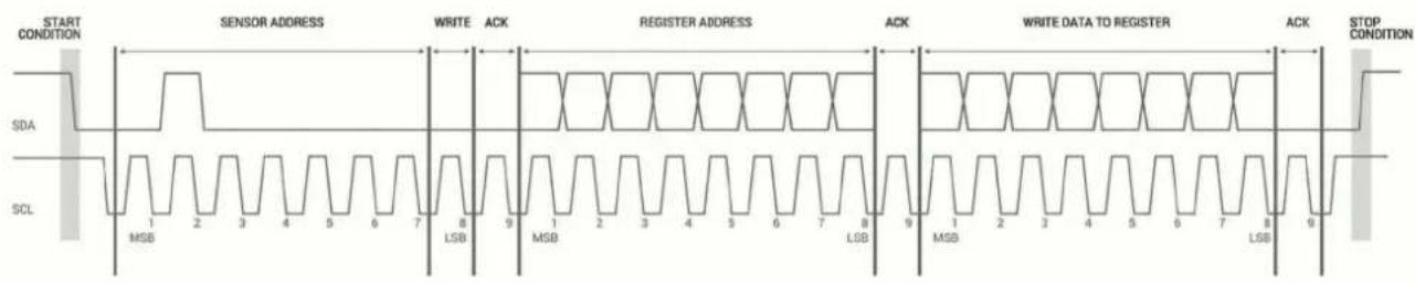
The sensor module has a 7-bit slave address with a default value of 0x62 in hexadecimal notation. The effective 8 bit I2C address is 0xC4 write, 0xC5 read. The device will not respond to a general call.
The last NACK in the read is optional, but the formal I2C protocol states that the master shall not acknowledge the last byte.
I2C Protocol Operation
This protocol description uses the term master to refer to the host controller, and the term LIDAR device to refer to the LIDAR-Lite v4 LED device acting as a slave on the I2C bus.
When working with the I2C serial bus protocol, the LIDAR device operates as follows.
1 The master initiates data transfer by establishing a start condition, which consists of a high-to-low transition on the SDA line while SCL is high.
2 The master sends an address byte, which consists of the 7-bit slave address.
3 The master sends a read/write bit with a zero state, which indicates a write request. A write operation is used as the initial stage of both read and write transfers.
4 If the slave address corresponds to the LIDAR device address, the LIDAR device responds by pulling SDA low during the ninth clock pulse. This operation is considered the acknowledge bit. At this stage, all other devices on the bus remain idle while the selected LIDAR device waits for data to be written to or read from its shift register.
5 Data transmits over the serial bus in sequences of nine clock pulses (eight data bits followed by an acknowledge bit).
These transmissions must occur on the SDA line during the low period of SCL and remain stable during the high period of SCL.
6 The master sends an 8-bit data byte following the slave address, which loads the I2C control register on the LIDAR device with the address of the first control register to be accessed.
7 The master requests a read operation from the LIDAR device or sends a write operation to the LIDAR device.
Read Operation
After the master establishes communication with the LIDAR device, you can obtain a reading from the LIDAR device.
1 The first data frame sets the address of the desired read register.
2 The master sends a stop bit at the completion of the first data frame.
3 The master initiates a new start condition, which consists of the slave I2C device address with the read bit set (one state).
4 The LIDAR device sends an acknowledge bit to the master when it receives a valid address.
5 The master reads one or more data bytes in succession. The internal device address pointer auto increments with each byte access.
6 The master strobes the acknowledge bit following each data byte except for the final byte in the transfer before sending the stop condition.
7 After the read cycle is done, the master sends a stop condition to complete the operation.
Write Operation
After the master establishes communication with the LIDAR device, writing to the LIDAR device operates as follows.
1 The master sends one or more 8-bit data blocks to the LIDAR device. The internal device address pointer auto increments with each byte access.
2 The LIDAR device sends an acknowledge bit to the master when it receives and writes a valid data byte.
3 After the write cycle is done, the master sends a stop condition to complete the operation.
Control Register List
NOTE: Unless otherwise noted, all registers contain one byte and are read and write.
| Address R/W Name Description Initial Value Details | |||||
| 0x00 W A | CQ_ | COMMANDS Device command | -- 0x00, page 5 | ||
| 0x01 R S | TATUS | System status -- 0x01, page 5 | |||
| 0x05 | R/W | ACQUISITION_COUNT | Maximum acquisition count | 0xFF | 0x05, page 6 |
| 0x10 | R | FULL_DELAY_LOW | Distance measurement low byte | -- | 0x10, page 6 |
| 0x11 | R | FULL_DELAY_HIGH | Distance measurement high byte | -- | 0x11, page 6 |
| 0x16 | R | UNIT_ID_0 | Unit ID, byte 0 | -- | 0x16, page 6 |
| 0x16 | W | UNIT_ID_0_UNLOCK | Write unit ID 0 for I2C address unlock | -- | 0x16, page 6 |
| 0x17 | R | UNIT_ID_1 | Unit ID, byte 1 | -- | 0x17, page 6 |
| 0x17 | W | UNIT_ID_1_UNLOCK | Write unit ID 1 for I2C address unlock | -- | 0x17, page 6 |
| 0x18 | R | UNIT_ID_2 | Unit ID, byte 2 | -- | 0x18, page 6 |
| 0x18 | W | UNIT_ID_2_UNLOCK | Write unit ID 2 for I2C address unlock | -- | 0x18, page 6 |
| 0x19 | R | UNIT_ID_3 | Unit ID, byte 3 | -- | 0x19, page 6 |
| 0x19 | W | UNIT_ID_3_UNLOCK | Write unit ID 3 for I2C address unlock | -- | 0x19, page 6 |
| 0x1A | R/W | I2C_SEC_ADDR | Write new I2C address after unlock | -- | 0x1A, page 6 |
| 0x1B | W | I2C_CONFIG | Default address response control | 0x00 | 0x1B, page 6 |
| 0x1C | R/W | DETECTION_SENSITIVITY | Peak detection threshold bypass | 0x00 | 0x1C, page 6 |
| 0x30 | R | LIB_VERSION | Read Garmin software library version string | -- | 0x30, page 7 |
| 0x52 | R/W | CORR_DATA | Correlation record data control | -- | 0x52, page 7 |
| 0x72 | R | CP_VER_LO | Coprocessor firmware version low byte | -- | 0x72, page 7 |
| 0x73 | R | CP_VER_HI | Coprocessor firmware version high byte | -- | 0x73, page 7 |
| 0xE0 | R | BOARD_TEMPERATURE | Board temperature | -- | 0xE0, page 7 |
| 0xE1 | R | HARDWARE_VERSION | Board hardware version | -- | 0xE1, page 7 |
| 0xE2 | R/W | POWER_MODE | Power state control | 0xFF | 0xE2, page 7 |
| 0xE3 | R/W | MEASUREMENT_INTERVAL | Automatic measurement rate | 0xFF | 0xE3, page 7 |
| 0xE4 | W | FACTORY_RESET | Reset default settings | -- | 0xE4, page 7 |
| 0xE5 | R/W | QUICK_TERMINATION | Quick acquisition termination | 0x08 | 0xE5, page 7 |
| 0xE6 | W | START_BOOTLOADER | Start secure Bluetooth LE bootloader | -- | 0xE6, page 7 |
| 0xEA | R/W | ENABLE_FLASH_STORAGE | Store register settings | 0x00 | 0xEA, page 7 |
| 0xEB | R/W | HIGH_ACCURACY_MODE | Improved accuracy setting | 0x14 | 0xEB, page 8 |
| 0xEC | R | SOC_TEMPERATURE | SoC temperature | -- | 0xEC, page 8 |
0x00
| R/W | Name | Description | Initial Value |
| W | ACQ_COMMANDS | Device command | -- |
Bit Function
| 7:0 | Write 0x03: Take distance measurement without receiver bias correctionWrite 0x04: Take distance measurement with receiver bias correction |
0x01
| R/W | Name | Description Initial Value | |
| R | STATUS | System status | -- |
Bit Function
| 5 | DC error flag0: No error detected1: An error was detected in correcting DC noise bias, and distance measurements are expected to be inaccurate |
| 4 | DC bias done flag0: The device is performing automatic DC noise bias corrections1: DC noise is within tolerance, and the automatic DC noise bias corrections are currently idle |
| 3 | Low power flag0: Device is powered on. I2C commands can be issued at a normal rate.1: The device is in low power mode. To allow the device to power on and perform the I2C command, a 10ms delay after each command is recommended. |
Bit Function
| 2 Reference overflow flag0: Reference data has not overflowed1: Reference data in correlation record has reached the maximum value before overflow (this occurs when taking measurements with biasing enabled) |
| 1 Signal overflow flag0: Signal data has not overflowed1: Signal data in correlation record has reached the maximum value before overflow (this occurs with a strong received signal strength) |
| 0 Busy flag0: Device is ready for a new command1: Device is busy taking a measurement or powering on |
0x05
| R/W | Name Description Initial Value | ||
| R/W | ACQUISITION_COUNT | Maximum acquisition count | 0xFF |
Bit Function
| 7:0 Maximum number of acquisitions during measurement |
0x10
| R/W Name Description Initial Value | ||
| R FULL_DELAY_LOW Distance measurement low byte | -- | |
Bit Function
| 7:0 Distance measurement result in centimeters, low byte. |
0x11
| R/W | Name Description Initial Value | ||
| R | FULL_DELAY_HIGH | Distance measurement high byte | -- |
Bit Function
| 7:0 Distance measurement result in centimeters, high byte. |
0x16
| R/W Name Description Initial | Value | ||
| R UNIT_ID_0 Unit ID, byte 0 | -- | ||
| W UNIT_ID_0_UNLOCK Write unit ID 0 for I2C address unlock | -- | ||
Bit Function
| 7:0 | Read byte zero (LSB) of the unit IDWrite the value in UNIT_ID_0 here as part of enabling a non-default I2C address. See I2C_SEC_ADDR (0x1A, page 6). |
0x17
| R/W Name Description Initial | Value | ||
| R UNIT_ID_LOW | Unit ID, byte 1 -- | ||
| W UNIT_ID_1_UNLOCK | Write unit ID 1 for I2C address unlock | -- | |
Bit Function
| 7:0 Read byte one of the unit IDWrite the value in UNIT_ID_1 here as part of enabling a non-default I2C address. See I2C_SEC_ADDR (0x1A, page 6). |
0x18
| R/W | Name Description Initial | Value | |
| R UNIT_ID_2 Unit ID, byte 2 | -- | ||
| W UNIT_ID_2_UNLOCK Write unit ID 2 for I2C address unlock | -- | ||
Bit Function
| 7:0 | Read byte two of the unit IDWrite the value in UNIT_ID_2 here as part of enabling a non-default I2C address. See I2C_SEC_ADDR (0x1A, page 6). |
0x19
| R/W Name Description Initial | Value | ||
| R UNIT_ID_3 Unit ID, byte 3 | -- | ||
| W UNIT_ID_3_UNLOCK Write unit ID 3 for I2C address unlock | -- | ||
Bit Function
| 7:0 | Read byte three (MSB) of the unit ID.Write the value in UNIT_ID_3 here as part of enabling a non-default I2C address. See I2C_SEC_ADDR (0x1A, page 6). |
0x1A
| R/W | Name | Description | Initial Value |
| R/W | 12C_SEC_ADDR | Write new I2C address after unlock | -- |
Bit Function
| 7:0 Non-default I2C address. |
| Available addresses are any non-zero 7-bit values.The five byte sequence is composed of the four byte UNIT_ID and the one byte slave address. The UNIT_ID must be entered with the least significant byte first. |
| UNIT_ID_0_UNLOCK (0x16, page 6), UNIT_ID_1_UNLOCK (0x17, page 6), UNIT_ID_2_UNLOCK (0x18, page 6), and UNIT_ID_3_UNLOCK (0x19, page 6) must have the correct value for the device to respond to the non-default I2C address. |
| Example: UNIT_ID = 0x01020304, (LSB = 04, MSB = 01)Example write starting at 0x16: 0x0403020155, would match on UNIT_ID and set slave address to 0x55 (The effective 8-bit secondary I2C address would be 0xAA write and 0xAB read) |
| NOTE: You must enable ENABLE_FLASH_STORAGE before configuring the secondary I2C address (0xEA, page 7). After the secondary address is configured, ENABLE_FLASH_STORAGE can be turned off and the I2C_SEC_ADDR remains operational. |
0x1B
| R/W | Name | Description | Initial Value |
| R/W | I2C_CONFIG | Default address response control | 0x00 |
Bit Function
| 7:0 | 0x00: Use the default address only (0x62). |
| 0x01: Use the secondary I2C address only. This requires the address to be configured using write command I2C_SEC_ADDR (0x1A, page 6). | |
| 0x02: Use both addresses. | |
| NOTE: As a backup, value 0x01 does not persist in NVM. If the device is reset, both I2C addresses are enabled (0x02). |
0x1C
| R/W | Name | Description | Initial Value |
| R/W | DETECTION_SENSITIVITY | Peak detection threshold bypass | 0x00 |
Bit Function
| 7:0 | 0x00: Use default valid measurement detection algorithm based on the peak value, signal strength, and noise in the correlation record. 0x01 to 0xFF: Set simple threshold for valid measurement detection. Values 0x20 to 0x60 generally perform well. |
0x30
| R/W Name Description Initial Value | |||
| R LIB_VERSION Read Garmin software library version string | -- | ||
Bit Function
| 7:0 | Read 11 consecutive bytes in one I2C read for the full library version string. Each byte represents a character using ASCII encoding. |
0x52
| R/W Name Description Initial Value | ||
| R/W CORR_DATA Correlation record data control -- | ||
Bit Function
| 7:0 | Read two consecutive bytes to retrieve correlation record data as a 16-bit, two's complement value. The memory index is incremented automatically, and successive two-byte reads produce sequential data.Write 0x00: Reset correlation internal pointer to zero. |
0x72
| R/W | Name Description Initial Value | |
| R | CP_VER_LO Coprocessor firmware version low byte. | -- |
Bit Function
| 7:0 Coprocessor firmware version low byte. |
0x73
| R/W | Name Description Initial Value | |
| R CP | VER_HI Coprocessor firmware verison high byte | -- |
Bit Function
| 7:0 Coprocessor firmware version high byte. |
0xE0
| R/W | Name | Description | Initial Value |
| R | BOARD_TEMPERATURE | Board temperature | -- |
Bit Function
| 7:0 | Returns the board's temperature as an 8-bit, two's complement value in Celsius. |
0xE1
| R/W | Name | Description | Initial Value |
| R | HARDWARE_VERSION | Board hardware version | -- |
Bit Fu
| 7:0 Board | hardware version |
0xE2
| R/W Name | Description | Initial Value |
| R/W POWER_MODE | Power state control | 0xFF |
Bit Function
| 7:0 | 0x00: Asynchronous Mode. The coprocessor is always OFFunless a distance measurement is requested or a register accessis required0x01: Synchronous Mode. Distance measurement is tied to theANT channel period. The coprocessor is turned on and off asrequired.0xFF: Always on. The coprocessor is not turned off, allowing forthe fastest measurements possible.NOTE: You must disable HIGH_ACCURACY_MODE before youadjust the power mode. |
0xE3
| R/W | Name Description | Initial | Value |
| R/W | MEASUREMENT_INTERVAL | Automatic measurement rate | 0xFF |
Bit Function
| 7:0 | This register is used in conjunction with Synchronous Mode(0xE2, page 7).0x00 and 0xFF: Trigger a distance measurement for every ANTmessage0x01 to 0xFE: The number of ANT channel periods to wait beforetriggering a distance measurement, effectively reducing theautomatic measurement rate.HIGH_ACCURACY_MODE must be disabled before adjusting themeasurement interval (0xEB, page 8). |
0xE4
| R/W | Name | Description | Initial Value |
| W FACTORY_RESET Reset default settings | -- | ||
Bit Function
| 7:0 | 0x01 to 0xFE: Resets the NVM/Flash storage information back to default settings and executes a SoftDevice reset. |
0xE5
| R/W | Name | Description | Initial Value |
| R/W | QUICK_TERMINATION | Quick acquisition termination | 0x08 |
Bit Function
| 7:0 | 0x00: Enable measurement quick termination. The device terminates the distance measurement early if it anticipates the signal peak in the correlation record will reach the maximum value. 0x08: Disable measurement quick termination. |
0xE6
| R/W | Name | Description | Initial Value |
| W | START_BOOTLOADER | Start secure Bluetooth LE bootloader. | -- |
Bit Function
| 7:0 | 0x01 to 0xFE: Restarts the device and launches the Bluetooth LE advertiser. All other functionality is disabled while using the Bluetooth LE bootloader. |
0xEA
| R/W | Name | Description | Initial Value |
| R/W | ENABLE_FLASH_STORAGE | store register settings | 0x00 |
Bit Function
| 7:0 | 0x00: Use RAM storage only. When the device is reset, default values are loaded. |
| 0x11: Use FLASH/NVM storage. Any register that supports both read and write operations is stored in NVM and persists over power cycles. When the device is reset, the values stored in NVM are loaded instead of the default values. | |
| NOTE: Use caution when enabling flash storage. The total number of writes and erases is limited to 10,000. |
0xEB
| R/W | Name Description Initial Value | ||
| R/W | HIGH_ACCURACY_MODE | Improved accuracy setting | 0x14 |
Bit Function
| 7:0 | 0x00: Disable high accuracy mode. While high accuracy mode is disabled, you can adjust the POWER_MODE to Asynchronous Mode or Synchronous Mode if required (0xE2, page 7).0x01 to 0xFF: Enable high accuracy mode. The value is used as the number of distance measurements to accumulate and average before returning them to the user. You must set the POWER_MODE to Always On before you adjust to a non-zero value. |
0xEC
| R/W Name Description Initial Value | ||
| R SOC_TEMPERATURE SoC temperature -- | ||
Bit Function
| 7:0 | Returns the temperature of the nRF SoC as an 8-bit, two's complement value in Celsius. |
0xF0
| R/W | Name Description Initial Value | ||
| R/W | ENABLE_ANT_RADIO | Enables ANT wireless communication | 0xFF |
Bit Function
| 7:0 | 0x00 Turn the ANT radio off |
| 0x55 Radio status is unavailable (read only) | |
| 0xFF Turn the ANT radio on (default) | |
| NOTE: As a backup, value 0x00 does not persist in NVM. If the device is reset, the radio is enabled (0xFF). |
Appendix
Reprogramming the nRF52840 SoC
NOTICE
Reprogramming the nRF52840 System on Chip (SoC) removes all pre-programmed factory software. The device comes preprogrammed with a unique ANT ID to ensure each device can be uniquely identified over the ANT wireless protocol. When reprogramming the device, special precautions should be taken to preserve the ANT ID value. See https://github.com/garmin/ for information about accessing and retaining the ANT ID value.
The LIDAR-Lite v4 LED device comes preprogrammed from the factory with a Bluetooth LE secure DFU bootloader for receiving wireless software updates. When reprogramming the nRF52840, the bootloader is removed. If you require a bootloader after reprogramming the device, you can follow the Bluetooth LE Secure DFU Bootloader reference design in the Nordic nRF5 SDK. If a boot pin is required, you should configure it to one of the exposed GPIOs (LIDAR-Lite v4 LED Connection Diagram, page 1).
Before you can reprogram the device, you must connect it to a compatible debugging probe.
The header on the LIDAR-Lite v4 LED device provides access to the nRF52840 SoC. You can reprogram the nRF52840 SoC to suit the individual needs of your project. Software development should be completed using the C programming language and the Nordic nRF5 SDK. For more information about the capabilities of the nRF52840, go to www.nordicsemi.com/nrf52840.
- For information about setting up a LIDAR-Lite v4 LED development environment, go to https://github.com/garmin/.
- For support in using the nRF5 SDK and reprogramming the nRF52840 SoC, go to https://devzone.nordicsemi.com/.
10-pin J-Link Wiring
You should connect the 10-pin J-Link debugging probe to the LIDAR-Lite v4 LED device as shown in the diagram and table below.
NOTE: A 10-pin J-link debugging probe cannot supply power to the LIDAR-Lite v4 LED device. Connections 1 and 2 are connected to the device from an external power supply. The power supply and debugging probe should share a common ground at pin 2 on the LIDAR-Lite v4 LED device.
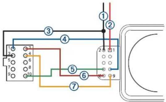
| Connection | 10-Pin J-Link Debugging Probe Pin | LIDAR-Lite v4 LED Pin |
| 1 | -- 2 (GND) to common ground | |
| 2 | -- 1 (VIN) to power source | |
| 3 | 3 (GND) to common ground -- | |
| 4 | 1 (VCC) 7 (VRETURN) | |
| 5 | 10 (nRESET) 8 (nRESET) | |
| 6 | 2 (SWDIO) 10 (SWDIO) | |
| 7 | 4 (SWCLK) | 9 (SWCLK) |
20-pin J-Link Wiring
You should connect the 20-pin J-Link debugging probe to the LIDAR-Lite v4 LED as shown in the diagram and table below.

| Connection | 20-Pin J-Link Debugging Probe Pin | LIDAR-Lite v4 LED Pin |
| 1 | 7 (SWDIO) 10 (SWDIO) | |
| 2 | 1 (VCC) 7 (VRETURN) | |
| 3 | 20 (GND) 2 (GND) | |
| 4 | 15 (nRESET) 8 (nRESET) | |
| 5 | 19 (5V Supply) 1 (5V) | |
| 6 | 9 (SWCLK) 9 (SWCLK) | |
| 7 | Short 11 to 12 Not applicable |
Standard Arduino® DUE I2C Wiring
NOTICE
The LIDAR-Lite v4 LED maximum signal level is 3.3 V. A signal greater than 3.3 V will damage the device.
You should connect the Arduino DUE and the LIDAR-Lite v4 LED as shown in the diagram and table.
NOTE: You must splice the ground wires so all components share a common ground. These components include the power supply, the programmer, the microcontroller operating I2C, and any GPIOs.

| Item Arduino DUE LIDAR-Lite v4 | LED | V Max | |
| 1 | 5V 1 (5 V) 5 V | ||
| 2 | GND 2 (GND) -- | ||
| 3 | SDA 20 3 (SDA) 3.3 V | ||
| 4 | SCL 21 | 4 (SCL) 3.3 V | |
| 5 | PWM 3 | 6 (GPIOB) | 3.3 V |
| 6 | PWM 2 | 5 (GPIOA) | 3.3 V |
Troubleshooting
Product Support
Contact your authorized Garmin Reseller for troubleshooting information related to your device and its specific application.
Go to support.garmin.com for general help and information, such as product manuals, specifications, and frequently asked questions.
The I2C is not responsive while the device is powered on
GPIO B is used as a boot pin to start the LIDAR-Lite v4 LED Bluetooth LE bootloader. If GPIO B is grounded when the device is powered on, the bootloader is enabled and I2C and ANT functionality are disabled.
Verify GPIO B is not grounded.
I cannot connect my device to the Garmin PC simulator
- Ensure the ANT network key is configured correctly.
If the LIDAR-Lite v4 LED device still has the default application installed from the factory, verify that you have the Garmin developer key selected.
If you have reprogrammed the device and you are using the public network key, verify that you have the public network key selected.
- Verify that you have the same RF frequency selected on both the LIDAR-Lite v4 LED device and the Garmin PC simulator.
- Verify that you have the correct channel parameters selected. TIP: You can set wildcards for the channel parameters to connect to any device. On the PC simulator, if you set the device number and transmission type to zero, the Garmin PC simulator connects to a device with any device number and transmission type.
Can I use a microcontroller with 5 V signaling?
The LIDAR-Lite v4 LED device is tolerant to only 3.3 V. If you need to use a 5 V system, such as the Arduino Uno, you must use a logic level converter to protect the I/O drivers in the LIDAR-Lite v4 LED device. Garmin does not endorse or recommend using a microcontroller with 5 V signaling.
© 2019–2020 Garmin Ltd. or its subsidiaries
Garmin ^2 , the Garmin logo, and ANT ^® are trademarks of Garmin Ltd. or its subsidiaries, registered in the USA and other countries.
Arduino ^2 is a registered trademark of Arduino AG. The BLUETOOTH ^® word mark and logos are owned by the Bluetooth SIG, Inc. and any use of such marks by Garmin is under license. J-Link is a trademark of SEGGER Microcontroller GmbH. Nordic Semiconductor ^2 is a trademark of Nordic Semiconductor ASA.
- Mounting Options
- Labeling Requirements
- Connections
- LIDAR-Lite v4 LED Connection Diagram
- NOTICE
- Operational Information
- Technology
- Theory of Operation
- Interface
- Initialization
- I2C Interface
- Obtaining Measurements from the I2C Interface
- Settings
- Configurable I2C Address
- Mode Control Pins
- Triggering and Reading Distance Measurements
- ANT
- Connecting Wirelessly Using ANT
- Activating the Bluetooth LE Bootloader
- I2C Protocol Information
- I2C Protocol Operation
- Read Operation
- Write Operation
- Control Register List
- Appendix
- Reprogramming the nRF52840 SoC
- 10-pin J-Link Wiring
- 20-pin J-Link Wiring
- Standard Arduino® DUE I2C Wiring
- Troubleshooting
- Product Support
- The I2C is not responsive while the device is powered on
- I cannot connect my device to the Garmin PC simulator
- Can I use a microcontroller with 5 V signaling?
Brand : GARMIN
Model : LIDAR-Lite v4 LED
Category : Capteur lidar