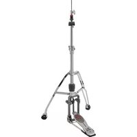
H-2050 - Computer Drum Pearl Sports - Free user manual and instructions
Find the device manual for free H-2050 Pearl Sports in PDF.


| Product Type | Computer Tower Case |
| Brand | Pearl Sports |
| Model | H-2050 |
| Form Factor | ATX Mid Tower |
| Max Motherboard Support | ATX, Micro-ATX, Mini-ITX |
| Dimensions (H x W x D) | 18.9 x 8.3 x 19.3 inches (approx.) |
| Weight | 12.5 lbs (approx.) |
| Material | Steel, Plastic front panel |
| Drive Bays | 2 x 3.5", 2 x 2.5" |
| Expansion Slots | 7 |
| Fan Support | Front: 2 x 120mm, Rear: 1 x 120mm |
| Power Supply | ATX PS2 (not included) |
| Front I/O Ports | USB 3.0 x2, USB 2.0 x2, Audio In/Out |
| Maximum GPU Length | Up to 13 inches |
| Maximum CPU Cooler Height | Up to 6.3 inches |
| Dust Filters | Front and bottom washable filters |
| Side Panel | Tempered glass window (left side) |
| Lighting | None |
| Cleaning | Use a soft dry cloth; remove dust filters regularly |
| Safety | Follow standard PC assembly safety guidelines; ensure proper grounding |
| Spare Parts | Contact Pearl Sports support for spare screws, panels, and filters |
Frequently Asked Questions - H-2050 Pearl Sports
User questions about H-2050 Pearl Sports
0 question about this device. Answer the ones you know or ask your own.
Ask a new question about this device
Download the instructions for your Computer Drum in PDF format for free! Find your manual H-2050 - Pearl Sports and take your electronic device back in hand. On this page are published all the documents necessary for the use of your device. H-2050 by Pearl Sports.
USER MANUAL H-2050 Pearl Sports
Congratulations on your purchase!
To get optimum performance of your H-2050 Hi-Hat Stand, please read this Instruction Manual before playing.
Power shifter
ELIMINATOR


Base Assembly
Hold the Pedal Frame with one hand. Loosen the Key Bolt on the Support Casting and disengage the Tab (Fig.1-A). Remove the Pedal Frame from the Docking Station as shown (Fig.1-B), and tighten the Key Bolt to prevent noise while performance.

Loosen the Key Bolts on both sides of the bottom of the Support Casting, and open up the Clamp (Fig.2-A). Insert the Strut Ends at the end of the Pedal Frame into the Clamps at the angle shown (Fig.2-B). Make sure that the Strut Ends are inserted all way in, and then rotate the Pedal Frame downward as shown (Fig.2-C). Tighten the Key Bolts on the Clamps to secure the Strut Ends.
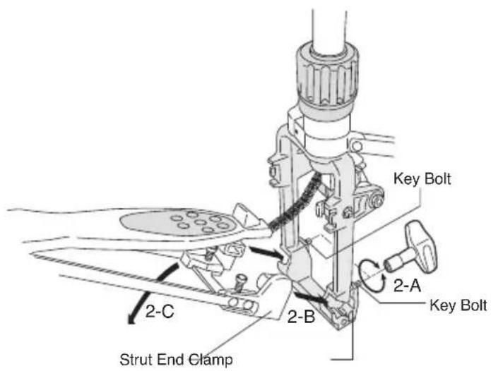
Fig.2-A, 2-B, 2-C
Stand the base up and holding it with one hand, loosen the Wing Bolt and open the legs. Make sure that the legs are forming a stable tripod, and tighten the Wing Bolt to retain setting (Fig.3).

Fig. 3
Make sure both the Support Casting and the Heel part of the Footboard are touching the playing surface, and that the stand is set vertically (Fig. 4).

CAUTION
Do not use the stand tilted. It would lose stability and would cause the stand to fall over.
The legs can be swiveled to fit your setting. Loosen the Wing Bolt and the Key Bolt as shown in (Fig.5). Swivel the legs to the desired position and tighten the Wing Bolt and Key Bolt to retain the setting.

Fig. 5
CAUTION
Depending on the position of the legs, the stand could become unstable and fall over. Make sure that the stand itself is stable before performance.
Upper Section Assembly
Thread the Upper Pull Rod into the Connector inside the Die Cast Joint as shown in (Fig.6-A) and tighten securely. Insert the Upper Tube into the Die Cast Joint and set the height to your preference then tighten the Wing Nut. Set the Stop Lock by loosening the Key Bolt and sliding the Stop Lock against the Die Cast Joint, then retighten the Key Bolt. Thread the Lower Hi-Hat Cymbal through the Upper Pull Rod and place it on the Hi-Hat Cup. Assemble the Top Hi-Hat Cymbal and the Hi-Hat Clutch as shown in (Fig.6-B). Tighten the Key Bolt on the Bottom Nut (Fig.6-C) to prevent it from loosening during performance. Mount the Clutch with the Top Hi-Hat Cymbal attached to the Upper Pull Rod. Adjust the distance between the top and bottom cymbals to your preference then secure the Clutch by tightening the Wing Nut.

Hi-Hat Cup Tilt Adjustment
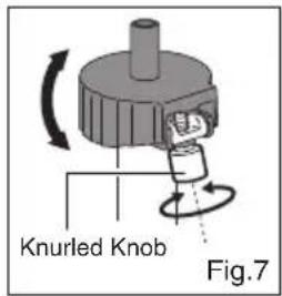
Turn the Knurled Knob to tilt the bottom cymbal to help prevent "air lock" between the cymbals (Fig.7).
VariSet Footboard Angle Adjustment
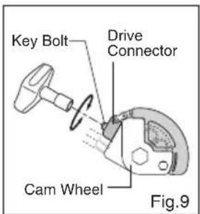
The Footboard angle can be adjusted in two ways. By loosening the Key Bolt on the Pull Cam, you can change the Footboard angle infinitely (Fig.8). You can also change the angle by loosening the Key Bolt on the Cam Wheel, and sliding the Drive Connector to one of the three positions (Fig.9). Make sure to tighten the Key Bolts after adjustments.

Tip
If the Footboard angle is set too high or too low, the action of the Release Button (for the Interchangeable Cam system) can be impaired. Should this happen, slightly readjust the angle of the Pull Cam until the Release Button moves freely.
PowerShifter Adjustment
The PowerShifter function allows the feel of the pedal to be changed from Strong, Normal, and Light.
To change the feel, loosen the Key Bolt on the Heel Plate and move the Footboard to the A, B, or C position. Tighten the Key Bolt to secure the Footboard (Fig.10).

A: Strong feel
B : Normal feel
C : Light feel
Fig.10
Spring Tension Adjustment
The spring tension can be adjusted quickly and precisely by turning the Spring Tension Dial. This innovative system features extended tension range and click-stops for slip-proof performance under the most demanding playing conditions (Fig.11).

Interchangeable Cams
Our exclusive Cam System provides four interchangeable color-coded cams (black, white, blue and red) allowing you to quickly change the power and feel of the pedal to suit your individual playing style. From the factory, the Black Cam is mounted. To change Cams, push the Release Button on the Wheel housing and remove the Cam as shown (Fig.12). To attach the Cam, it is not necessary to press the Release Button, simply snap the Cam onto the Wheel as shown (Fig.13). Check to make sure that the Cam is seated correctly and is secure to the Wheel housing.

Note
- Do not force the Cam onto the Wheel. If needed adjust the position of the Cam to fit properly.
- Do not use the pedal without the Cam attached, damage may occur.
| Included 4 Optional 2 | |
| Black Blu/WhiteRed | Yellow |
Black : Linear Action Cam
This is Pearl's original "perfect circle" Cam design. It offers superior power and a very natural, perfectly balanced action and smooth feel.
White : Oversized Linear Cam
The White Cam is a slightly over sized "perfect circle" Cam. It offers a very natural, smooth action, with great power and balance, with a slightly lighter pedal feel.
Blue : Progressive Cam
This is the very popular "off-center" axis type Cam design. It offers a light feel in the beginning that accelerates with speed and power upon impact.
Red : Radical Progressive Cam
The Red Cam features an extreme "off-center" axis design. The action is similar to the Blue Cam but with a lighter feel at the beginning of the stroke.
Purple : Aggressive Action Cam
The Purple Cam provides aggressive acceleration for huge power and response, second only to the Red Cam. (CAM-PL)
Yellow : Inverse Action Cam
The Yellow Cam provides a slight inverse action. When maximum power is required, this is the Cam of choice. (CAM-YL)
Traction Grip and Traction Plate Adjustment
The Traction Grip dots can be totally removed or inserted as needed to custom tailor the amount of traction for your personal playing style. To remove the Traction Grip dots, loosen the Allen Screws holding the Traction Plate with the provided hexagonal wrench and remove the Traction Plate from the footboard (Fig.14). The Traction Plate is also reversible to provide just the right amount of grip at either the front or rear of the footboard (Fig.15).

CAUTION
When putting the Traction Plate back, finger-tighten the four screws to prevent cross-threading; then tighten the screws securely. Do not use the Pedal without the Traction Plate mounted. It could cause injury to your foot.
Convertible Spiked / Rubber Tipped Feet
For maximum slip prevention, the H-2050 is equipped with a push button activated Spike Tip. To activate the Spike Tip, push the button on the top as shown in Fig.16. To retract the Spike Tip, push the button on the side as shown in Fig.17.

The inscription "HH" on the Rubber Foot stands for "Hi-Hat" and is the factory set position for the H-2050. Do not change this setting for best performance (Fig.18).

Fig.18
CAUTION
The Spikes are sharp and can cause serious personal or property injury. To prevent mishaps, use extreme care when handling the stand especially when the Spike Tips are exposed. A rug or carpet should be used to protect floor surfaces whenever the Spikes are used.
Dismantling the Pedal Frame
Loosen the two Key Bolts on both side of the bottom of the Support Casting, open the Clamp and remove the Pedal
Frame from the Support Casting. Loosen the Key Bolt on the Docking Station and disengage the Tab. Locate the square slot on the Strut End and the square prong on the Docking Station. Make sure that they are aligned and insert the Strut End into the Docking Station. Keep the Docking Station and the Pedal Frame parallel to each other (Fig.19).

Fig.19
Tighten the Key Bolt to secure the Pedal Frame to the Docking Station. Make sure the Tab is properly seated as shown before tightening the Key Bolt to prevent damage to the Tab and/or Key Bolt (Fig.20).
CAUTION
While docking, support the Pedal Frame to avoid injury.

Fig.20
Maintenance
The Base Tube (shown to the right) is secured to the Support Casting with Allen screws. In the event the Base Tube becomes loose, tighten the Allen screws with the provided hexagonal wrench to restore stability.


CAUTION
Periodically check all Allen Screws for tightness and tighten them with the provided hexagonal wrench as needed.
Periodically lightly lube external moving parts such as the Chain, Wing Nuts, Wing Bolts, Key Bolts, and Footboard Hinge to achieve optimum performance from your stand.
To maximize traction of the rubber mat beneath the heel plate, keep it clean and dust free using a damp cotton towel.
Pearl®
http://www.pearldrum.com
Products and specifications are subject to change without notice.
Printed in China
-1601-

- BASE ASSEMBLY
- CAUTION
- UPPER SECTION ASSEMBLY
- HI-HAT CUP TILT ADJUSTMENT
- VARISET FOOTBOARD ANGLE ADJUSTMENT
- TIP
- POWERSHIFTER ADJUSTMENT
- SPRING TENSION ADJUSTMENT
- INTERCHANGEABLE CAMS
- NOTE
- BLACK : LINEAR ACTION CAM
- WHITE : OVERSIZED LINEAR CAM
- BLUE : PROGRESSIVE CAM
- RED : RADICAL PROGRESSIVE CAM
- PURPLE : AGGRESSIVE ACTION CAM
- YELLOW : INVERSE ACTION CAM
- TRACTION GRIP AND TRACTION PLATE ADJUSTMENT
- CONVERTIBLE SPIKED / RUBBER TIPPED FEET
- DISMANTLING THE PEDAL FRAME
- MAINTENANCE
Brand : Pearl Sports
Model : H-2050
Category : Computer Drum