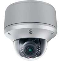
TruVision TVD-1204 - Surveillance Camera Interlogix - Free user manual and instructions
Find the device manual for free TruVision TVD-1204 Interlogix in PDF.


| Product Type | Surveillance Camera |
| Brand | Interlogix |
| Model | TruVision TVD-1204 |
| Resolution | 1280 x 720 (HD 720p) |
| Lens Type | Fixed focal length, 3.6mm |
| Night Vision | Up to 30 meters IR range |
| Video Compression | H.264 |
| Frame Rate | 25/30 fps at 720p |
| Power Supply | 12V DC, 1A |
| Power Consumption | Max 8W |
| Dimensions (W x H x D) | 135 x 85 x 85 mm |
| Weight | 0.4 kg |
| Mounting | Wall or ceiling mount |
| Protection Rating | IP66 (weatherproof) |
| Operating Temperature | -30°C to 60°C |
| Storage Temperature | -40°C to 70°C |
| Motion Detection | Yes, configurable |
| Audio | Built-in microphone (optional) |
| Maintenance | Clean lens with soft, dry cloth |
| Safety | Use approved power adapter; ensure secure mount |
| Spare Parts | IR LEDs, lens module, power adapter |
| Repairability | Contact authorized service center for repairs |
| Included Accessories | Mounting kit, screws, manual |
Frequently Asked Questions - TruVision TVD-1204 Interlogix
User questions about TruVision TVD-1204 Interlogix
0 question about this device. Answer the ones you know or ask your own.
Ask a new question about this device
Download the instructions for your Surveillance Camera in PDF format for free! Find your manual TruVision TVD-1204 - Interlogix and take your electronic device back in hand. On this page are published all the documents necessary for the use of your device. TruVision TVD-1204 by Interlogix.
USER MANUAL TruVision TVD-1204 Interlogix
TruVision 12/32 Series IP Camera Installation Guide
Copyright © 2015 United Technologies Corporation, Interlogix is part of UTC Building & Industrial Systems, a unit of United Technologies Corporation. All rights reserved.
Trademarks and patents Trade names used in this document may be trademarks or registered trademarks of the manufacturers or vendors of the respective products.
Manufacturer Interlogix
2955 Red Hill Avenue, Costa Mesa, CA 92626-5923, USA
Authorized EU manufacturing representative: UTC Fire & Security B.V.
Kelvinstraat 7, 6003 DH Weert, The Netherlands
Certification

FCC compliance Class A: This equipment has been tested and found to comply with the limits for a Class A digital device, pursuant to part 15 of the FCC Rules. These limits are designed to provide reasonable protection against harmful interference when the equipment is operated in a commercial environment. This equipment generates, uses, and can radiate radio frequency energy and, if not installed and used in accordance with the instruction manual, may cause harmful interference to radio communications. Operation of this equipment in a residential area is likely to cause harmful interference in which case the user will be required to correct the interference at his own expense.
ACMA compliance Notice! This is a Class A product. In a domestic environment this product may cause radio interference in which case the user may be required to take adequate measures.
Canada This Class A digital apparatus complies with Canadian
ICES-003.
European Union directives
12004/108/EC (EMC directive): Hereby, UTC Fire & Security declares that this device is in compliance with the essential requirements and other relevant provisions of Directive 2004/108/EC.

2012/19/EU (WEEE directive): Products marked with this symbol cannot be disposed of as unsorted municipal waste in the European Union. For proper recycling, return this product to your local supplier upon the purchase of equivalent new equipment, or dispose of it at designated collection points. For more information see: www.recyclethis.info.
Contact information For contact information, see www.interlogix.com or www.utcfssecurityproducts.eu.
Content
Introduction 2
Product overview 2
Installation 3
Installation environment 3
Package contents 4
Cable requirements 12
Camera description 13
Setting up the camera 17
IR illuminators 18
Accessing the SD card 19
Mounting the bullet camera 19
Mounting the VF dome camera 20
Mounting the outdoor dome camera 25
Using the camera with an Interlogix NVR or Hybrid DVR or another system 30
Using the camera with TruVision Navigator 30
Specifications 30
TruVision IP box cameras 30
TruVision IP VF outdoor dome cameras 32
Pin definitions 33
Installation Guide 1
Introduction
Product overview
This is the installation guide for TruVision 12/32 Series IP camera models:
• TVC-1201 (1.3MPX IP box camera, PAL)
• TVC-3201 (1.3MPX IP box camera, NTSC)
• TVC-1202 (3MPX IP box camera, PAL)
• TVC-3202 (3MPX IP box camera, NTSC)
• TVB-1201 (1.3MPX IP bullet camera, 2.8-12mm, PAL)
• TVB-3201 (1.3MPX IP bullet camera, 2.8-12mm, NTSC)
• TVB-1202 (3MPX IP bullet camera, 2.8-12mm, PAL)
• TVB-3202 (3MPX IP bullet camera, 2.8-12mm, NTSC)
• TVB-1203 (3MPX IP bullet camera, 8-32mm, PAL)
• TVB-3203 (3MPX IP bullet camera, 8-32mm, NTSC)
• TVD-1201 (1.3MPX IP VF mini dome, 2.8-12mm, PAL)
- TVD-3201 (1.3MPX IP VF mini dome, 2.8-12mm, NTSC)
• TVD-1202 (3MPX IP VF mini dome, 2.8-12mm, PAL)
• TVD-3202 (3MPX IP VF mini dome, 2.8-12mm, NTSC)
• TVD-1203 (1.3MPX IP outdoor dome, 2.8-12mm, PAL)
- TVD-3203 (1.3MPX IP outdoor dome, 2.8-12mm, NTSC)
• TVD-1204 (3MPX IP outdoor dome, 2.8-12mm, PAL)
• TVD-3204 (3MPX IP outdoor dome, 2.8-12mm, NTSC)
• TVD-1205 (3MPX IP outdoor dome, 8-32mm, PAL)
• TVD-3205 (3MPX IP outdoor dome, 8-32mm, NTSC)
Installation
This section provides information on how to install the cameras.
Installation environment
When installing your product, consider these factors:
- Electrical: Install electrical wiring carefully. It should be done by qualified service personnel. Always use a proper PoE switch or a 12 VDC UL listed Class 2 or CE certified power supply to power the camera. Do not overload the power cord or adapter.
- Ventilation: Ensure that the location planned for the installation of the camera is well ventilated.
- Temperature: Do not operate the camera beyond the specified temperature, humidity or power source ratings. The operating temperature of the camera without heater is between -30 to +60°C (-22 to 140°F). Humidity is below 90%. For the outdoor cameras have built-in heaters, the operating temperature range is -40°C to 60°C(-40°F to 140°F)
- Moisture: Do not expose the camera to rain or moisture, or try to operate it in wet areas. Turn the power off
immediately if the camera is wet and ask a qualified service person for servicing. Moisture can damage the camera and also create the danger of electric shock.
- Servicing: Do not attempt to service this camera yourself. Any attempt to dismantle or remove the covers from this product will invalidate the warranty and may also result in serious injury. Refer all servicing to qualified service personnel.
- Cleaning: Do not touch the sensor modules with fingers. If cleaning is necessary, use a clean cloth with some ethanol and wipe the camera gently. If the camera will not be used for an extended period of time, put on the lens cap to protect the sensors from dirt.
Package contents
Check the package and contents for visible damage. If any components are damaged or missing, do not attempt to use the unit; contact the supplier immediately. If the unit is returned, it must be shipped back in its original packaging.
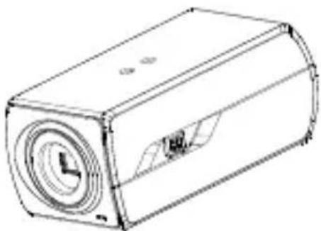
IP box camera
- Camera
- CD with Configuration manual and TruVision Device Finder

• WEEE and Battery Disposal

C-CS adaptor

• Installation manual
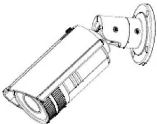
IP VF bullet camera
- Camera
- Template

- Screws M4.8 × 18, 4pcs to attach the back box

- Back box

- Alarm connector (2 pcs)

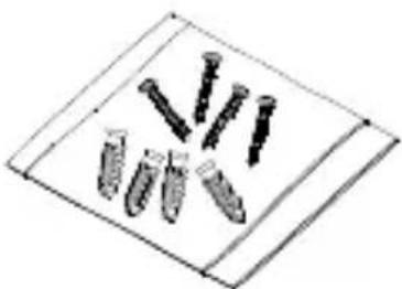
- Screws (4 pcs)
• Water joint: provide water resistance to network connection.

- CD with Configuration manual and TruVision Device Finder

• Installation manual

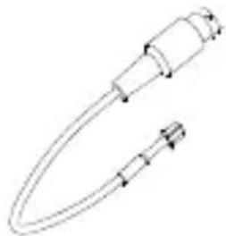
- Video cable
- Wrench

• WEEE and Battery Disposal

IP VF dome camera
- Camera

- Template


- Adaptor: for TVD-CB3 cup base

• 12 VDC Connector: DC jack socket to terminal connectors with positive and negative indicators.

• Water joint: provide water resistance to network connection.

- Screws C: M4×8, 3pcs

- Hex wrench

• Installation manual
Installation Guide 9
- Screws (4 pcs)
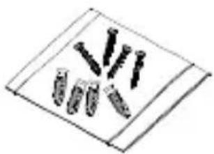
• Alarm connector (2 pcs)

- CD with Configuration manual and TruVision Device Finder

• WEEE and Battery Disposal

IP VF outdoor dome camera
- Camera

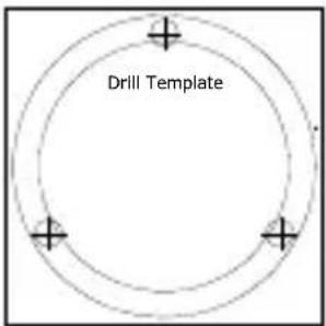
- Template (flush mount)
- Screws(4 pcs)

- Screws M4 × 9.5, 3pcs to attach the back box

- Back box

- Template (back box)

- Screws B (3 pcs)

- Wrench

- Alarm connector(4 pcs)

• Water joint: provide water resistance to network connection.

• Installation manual

- CD with Configuration manual and TruVision Device Finder

• WEEE and Battery Disposal

CAUTION: Use direct plug-in UL listed power supplies marked Class 2/CE certified or LPS (limited power source) of the required output rating as listed on the unit.
Cable requirements
For proper operation, adhere to the following cable and power requirements for the cameras. Category 5 cabling or better is recommended. All network cabling must be installed according to applicable codes and regulations.
Table 1 below lists the requirements for the cables that connect to the camera.
Table 1: Recommended power cable requirements
| Box camera | 12 VDC/24 VAC power wires or PoE (802.3af) |
| VF bullet camera: | 12 VDC power jack or PoE (802.3af) |
| VF mini dome: | 12 VDC power jack or PoE (802.3af) |
| VF outdoor dome: | 24 VAC power wires or PoE (802.3af) |
Camera description
Figure 1: IP bullet camera

- Ethernet RJ45 PoE port
- Power supply
- Reset button
- SD card
- BNC port
- Ground
-
Alarm Out
-
RS-232 serial port
- RS-485 port
- Alarm In
- Audio Out
- ABF (automatic back focus) button
- Audio In
Note:
-
To reset the camera to default settings, you need to press and hold the RESET button and power on the camera. After the camera is started up, please still hold the Reset button for about 20 seconds.
-
The type of auto-iris interface is shown as below figure:
| No. | DC-driven |
| 1 | Damp- |
| 2 | Damp+ |
| 3 | Drive+ |
| 4 | Drive- |
Power, Video and GND pins are used when the auto-iris is driven by video. Damp+, Damp-, Drive+ and Drive- pins are used when the auto-iris is driven by DC.
Figure 2: IP VF bullet camera

- Shield
- Lens cover
- Mounting base
- BNC output
- Back box
- Alarm I/O
- Reset button
- Power supply
- SD card slot
- Ethernet RJ45 PoE port
Figure 3: IP VF dome camera
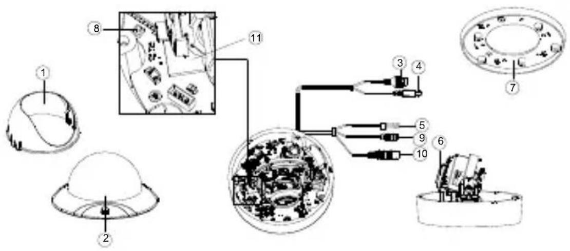
- Dome liner
- Bubble Assembly
- Ethernet RJ45
- Power cable
- Alarm cable
- Lens
- Adaptor
- Reset button
- RS485
- BNC cable
- SD card slot
Figure 4: IP VF outdoor dome camera

- Dome liner
- Bubble Assembly
- SD card
- Analog video output
-
Reset button
-
Ethernet RJ45 PoE port
- Power supply
- Lens
- Alarm I/O
Setting up the camera
Note: If the light source where the camera is installed experiences rapid, wide-variations in lighting, the camera may not operate as intended.
To quickly put the camera into operation:
- Prepare the mounting surface.
2 Mount the camera on the mounting surface using the appropriate fasteners. See “Mounting the bullet camera” on page 19. - Set up the camera's network and streaming parameters so that the camera can be controlled over the network. For further information, please refer to the “TruVision 12/32 series IP Camera Configuration Manual”.
- Program the camera to suit its location. For further information, please refer to the "TruVision 12/32 series IP Camera Configuration Manual".
IR illuminators
The camera's built-in IR illumination provides high-quality video in low-light environments, even when there is no other illumination available.
You can configure the IR illumination using a web browser or a client software. If the function is enabled, the IR light is On when the camera enters night (black and white) mode. If disabled, the IR light is always Off.
The visible IR range may vary due to multiple factors, such as weather, IR reflection rate of viewing objects, lens adjustment, and camera settings. Please refer to the camera datasheet for the standard IR range.
Note: Avoid installing the IR camera closely facing a tree or wall. The reflection will cause over-exposure and lose visibility of detail in field of view.
Accessing the SD card
Insert a Micro SD card with up to 64GB for local storage as a backup in case, for example, the network fails (see Figure 1 on page 13). The card is not supplied with the camera.
For the IP VF mini dome and outdoor dome cameras, point the lens vertically upwards to access the SD card slot.
Video and log files stored on the Micro SD card can only be accessed via the web browser. You cannot access the card using TruVision Navigator or a recording device.
Note: When using the SD card slot of the bullet camera, make sure that the lens cover is screwed back correctly on the camera.
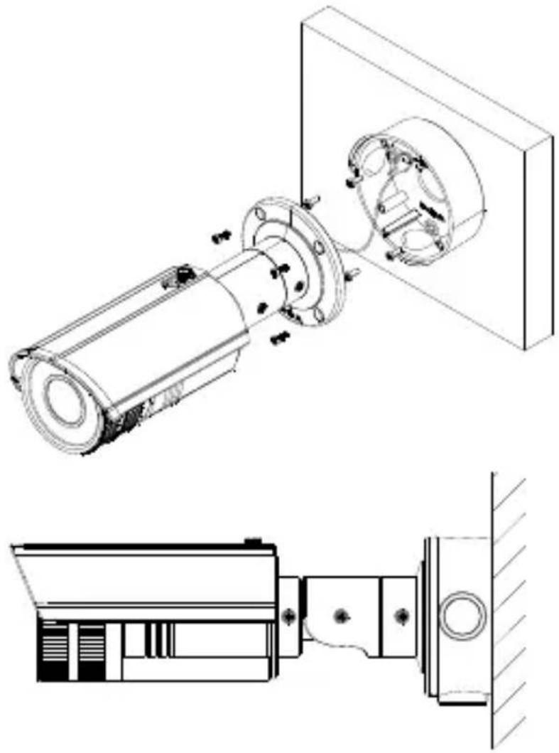
Mounting the bullet camera
Mount the camera on a ceiling or wall.
To mount the bullet camera:
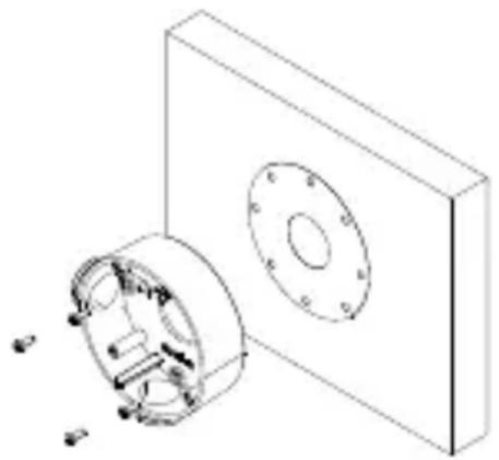
- Use the supplied template to mark out the mounting area. Drill the screw holes on the ceiling or wall. If you need to route the cables from the camera base, drill a cable hole in the ceiling or wall.
- Secure the back box to the ceiling or wall with the supplied screws.
Installation Guide 19
- Hook the camera to the back box with the safety cable. Use the screws to fix the camera to the back box.
Mounting the VF dome camera
To mount the VF dome camera on a ceiling or wall:
- Loosen the three screws on the edge of the lower dome with a wrench.

- Open the lower dome and remove the black inner liner.

- Using the drill template, drill three holes in the mounting surface.

Screw holes
-
If you want to route the cables behind the dome, drill a cable hole in the ceiling or wall using the drill template.
-
Mount the camera to the ceiling or wall by aligning the housing holes with those in the ceiling. Secure the camera with the supplied screws as shown below.

-
Route the cables through the side hole of the dome by removing the cover.
-
Connect the video output connector to the monitor. Connect the power connector to the power supply.
-
View the camera image using the monitor. Adjust the pan, tilt and azimuth angle. Loosen and adjust the zoom and focus lever to obtain the appropriate angle of view and optimum focus.
2) Zoom and focus adjustment.
Loosen the zoom lever and move the lever between T(Tele) and W(Wide) to obtain the appropriate angle of view.
3) Tighten the zoom lever.
Loosen the focus lever and move the lever between F(Far) and N(Near) to obtain the optimum focus.
Tighten the focus lever.
Tilting

Rotation
Mounting the outdoor dome camera
To mount the outdoor dome camera on a ceiling:
- Drill the screw holes on the ceiling with the supplied drilling template. To route the cables from the base of the camera, cut a cable hole in the ceiling.

- Install the mounting base to the ceiling with the supplied screws.

-
Connect the corresponding power cable and network cables.
-
Remove the bubble and liner of the camera.

- Install the dome camera to the mounting base.

- Adjust the surveillance angle.
1) Loosen the lock screw besides the lens.
2) Hold the plastic plate and rotate the camera to adjust the panning angle [0\~350°].
3) Push the lens forward and backward to adjust the tilting angle [0\~80°].
4) Rotate the lens to adjust the azimuth angle of the camera [0\~350°].
5) Tighten the lock screw.

- Re-attach the dome liner and bubble to the camera.

Installation Guide 27
To mount the outdoor dome camera into a ceiling:
- Drill the screw holes on the ceiling with the supplied drilling template.

- Remove the housing and liner from the camera.
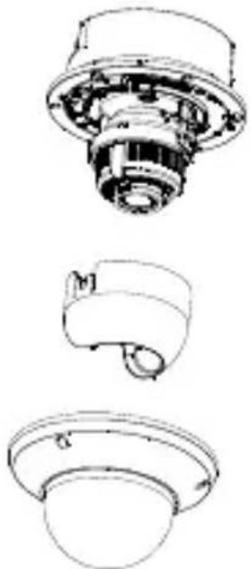
- Install the camera to the hole with three screw,

- Re-attach the housing and liner.

Using the camera with an Interlogix NVR or Hybrid DVR or another system
Please refer to the NVR/DVR user manuals for instructions on connecting and operating the camera with these systems.
Using the camera with TruVision Navigator
A camera must be connected to an Interlogix NVR or hybrid DVR in order to be operated by TruVision Navigator. Please refer to the TruVision Navigator user manual for instructions on operating the camera with the TruVision Navigator.
Specifications
TruVision IP box cameras
| Electrical | |
| Voltage input | 12 VDC/24 VAC, PoE (IEEE 802.3af) |
| Power consumption | 1.3MPX: Max. 6 W (max. 9 W with IR on)3MPX: Max. 6.5 W (max. 9.5 W with IR on) |
| Miscellaneous | |
| Connectors | AC/DC power, network, audio, alarm in/out and video |
| Operating temperature | -30 to +60 °C (-22 to +140°F) |
| Dimensions | 69.8 × 58 × 145 mm(2.68" × 2.56" × 5.70 in.) |
Weight 830g (1.83 lbs.)
| Electrical | |
| Voltage input 12 VDC, PoE (IEEE 802.3af) | |
| Power consumption | 1.3MPX: Max. 6 W (max. 8 W with IR on) |
| 3MPX: Max. 6.5 W (max. 8.5 W with IR on) | |
| Miscellaneous | |
| Connectors Alarm: screw terminal | |
| RS-485: screw terminal | |
| DC power: female connector | |
| RJ45: female connector | |
| BNC: female connector | |
| Operating temperature -30 to +60 °C (-22 to +140 °F) | |
| Dimensions | Φ 140 × 100 mm(Φ 5.51" × 3.94"in.) |
| Weight | 800 g |
| Environmental rating IP66 | |
TruVision IP VF bullet cameras
| Electrical |
| Voltage input 12 VDC, PoE (IEEE 802.3af) |
| Power consumption 1.3MPX: Max. 12 W |
| 3MPX: Max. 12.5 W |
| Miscellaneous |
| Connectors DC power: screw terminal |
| RJ45: female connector |
| Alarm: screw terminal |
| Operating temperature -30 to +60 °C (-22 to 140°F) |
| -40°C to +60°C (-40°F to +140°F), with heater on |
| Dimensions 98 x 105 × 328.8 mm |
| Weight 1700 g (3.75 lbs.) |
| Environmental rating IP66 |
TruVision IP VF outdoor dome cameras
| Electrical | |
| Voltage input 24 VAC, PoE (IEEE 802.3af) | |
| Power consumption Max. 12.5 W | |
| Miscellaneous | |
| Connectors AC power: screw terminalRJ45: female connectorAlarm wire | |
| Operating temperature -30 to +60°C (-22 to +140°F) | |
| -40 to +60°C (-40 to +140°F), with heater on | |
| Dimensions | Φ 159.8 × 146 mm(Φ 6.29" × 5.75"in.) |
| Weight 2100 g (4.62 lbs.) | |
| Environmental rating IP66, IK10 | |
Pin definitions
There are eight wires on a standard UTP/STP cable and each wire is color-coded. The following shows the pin allocation and color of straight and crossover cable connection:
Figure 5: Straight-through cable

Figure 6: Cross-over cable

Please make sure your connected cables have the same pin assignment and color as above before deploying the cables in your network.


- TRUVISION 12/32 SERIES IP CAMERA INSTALLATION GUIDE
- CERTIFICATION
- EUROPEAN UNION DIRECTIVES
- CONTENT
- INTRODUCTION 2
- INSTALLATION 3
- SPECIFICATIONS 30
- PIN DEFINITIONS 33
- INTRODUCTION
- PRODUCT OVERVIEW
- INSTALLATION
- INSTALLATION ENVIRONMENT
- PACKAGE CONTENTS
- IP BOX CAMERA
- IP VF BULLET CAMERA
- IP VF DOME CAMERA
- IP VF OUTDOOR DOME CAMERA
- CABLE REQUIREMENTS
- CAMERA DESCRIPTION
- NOTE
- SETTING UP THE CAMERA
- TO QUICKLY PUT THE CAMERA INTO OPERATION
- IR ILLUMINATORS
- ACCESSING THE SD CARD
- MOUNTING THE BULLET CAMERA
- TO MOUNT THE BULLET CAMERA
- MOUNTING THE VF DOME CAMERA
- MOUNTING THE OUTDOOR DOME CAMERA
- TO MOUNT THE OUTDOOR DOME CAMERA ON A CEILING
- TO MOUNT THE OUTDOOR DOME CAMERA INTO A CEILING
- USING THE CAMERA WITH AN INTERLOGIX NVR OR HYBRID DVR OR ANOTHER SYSTEM
- USING THE CAMERA WITH TRUVISION NAVIGATOR
- SPECIFICATIONS
- PIN DEFINITIONS
Brand : Interlogix
Model : TruVision TVD-1204
Category : Surveillance Camera