65BZW - Lighting Code 3 - Free user manual and instructions
Find the device manual for free 65BZW Code 3 in PDF.


| Product Type | Emergency Warning Light |
| Brand | Code 3 |
| Model | 65BZW |
| Dimensions (L x W x H) | 48 x 12 x 3 inches (typical) |
| Weight | 15 lbs (approx.) |
| Power Supply | 12V DC |
| Current Draw | 10A (typical) |
| Light Source | LED |
| Flash Patterns | Multiple selectable patterns |
| Synchronization | Master/Slave capable |
| Housing Material | Aluminum with polycarbonate lens |
| Mounting | Surface mount or bracket |
| Weather Resistance | IP65 (dust and water resistant) |
| Operating Temperature | -30°C to 60°C |
| Certifications | SAE, CE, ECE |
| Color Options | Red, Blue, Amber, White (depending on configuration) |
| Spotlight Function | Yes (directional option) |
| Maintenance | Clean with soft damp cloth and mild soap |
| Spare Parts Available | Yes, from Code 3 or authorized dealers |
| Warranty | 5 years (typical) |
Frequently Asked Questions - 65BZW Code 3
User questions about 65BZW Code 3
0 question about this device. Answer the ones you know or ask your own.
Ask a new question about this device
Download the instructions for your Lighting in PDF format for free! Find your manual 65BZW - Code 3 and take your electronic device back in hand. On this page are published all the documents necessary for the use of your device. 65BZW by Code 3.
USER MANUAL 65BZW Code 3


Code 3,® Inc., a subsidiary of Public Safety Equipment, Inc.
CODE 3® PUBLIC SAFETY EQUIPMENT, INC.
SERIES 45, 65, 85
LED PERIMETER, STOP/TURN/TAIL
Contents:
Introduction 2
Unpacking & Pre-Installation 2
Mounting Options 3
Installation & Wiring 3-6
Flash Pattern Selection 7
Power Requirements 7-8
Parts & Exploded View 8
Maintenance 9
Options 9
Warranty 12
IMPORTANT:
Read all instructions and warnings before installing and using. INSTALLER: This manual must be delivered to the end user of this equipment.
Introduction
The 45/65/85 Series LED Perimeter Light Heads are designed for the emergency vehicle market. The light heads are to be connected directly to +12 or +24 VDC systems for independent flashing or through electromechanical or solid state flasher units. These light heads with their unique optics are designed for full, optimized signals at all angles.
Models 45STR and 65STR (Red Stop-Turn-Tail); 45STA and 65STA (Amber Turn) meet the requirements for Stop-Turn-Tail lamps of Federal Motor Vehicle Safety Standard No. 108 and SAE specifications J2040, J2261 and J593. These units are to be installed only on the rear of the vehicle. The units are to be connected to the stop/tail, turn signal, and reverse light circuitry of the vehicle.
Consisting of an LED base unit, lens, o-ring, gasket, optional bezel and mounting screws, these units are easy to install.

WARNING!
The use of this or any warning device does not insure that all drivers can or will observe or react to an emergency warning signal. Never take the right-of-way for granted. It is your responsibility to be sure you can proceed safely before entering an intersection, driving against traffic, responding at a high rate of speed, or walking on or around traffic lanes.
The effectiveness of this warning device is highly dependent upon correct mounting and wiring. Read and follow the manufacturer's instructions before installing or using this device. The vehicle operator should insure daily that all features of the device operate correctly. In use, the vehicle operator should insure the projection of the warning signal is not blocked by vehicle components (i.e.: open trunks or compartment doors), people, vehicles, or other obstructions. This equipment is intended for use by authorized personnel only. It is the user's responsibility to understand and obey all laws regarding emergency warning devices. The user should check all applicable city, state and federal laws and regulations.
Public Safety Equipment, Inc., assumes no liability for any loss resulting from the use of this warning device.
Proper installation is vital to the performance of this warning device and the safe operation of the emergency vehicle. It is important to recognize that the operator of the emergency vehicle is under psychological and physiological stress caused by the emergency situation. The warning device should be installed in such a manner as to: A) Not reduce the output performance of the system, B) Place the controls within convenient reach of the operator so that he can operate the system without losing eye contact with the roadway.
Emergency warning devices often require high electrical voltages and/or currents. Properly protect and use caution around live electrical connections. Grounding or shorting of electrical connections can cause high current arcing, which can cause personal injury and/or severe vehicle damage, including fire. Wait 10 minutes after turning off the power from system before touching any internal components. Always wear hand and eye protection when handling electrical components.
PROPER INSTALLATION COMBINED WITH OPERATOR TRAINING IN THE PROPER USE OF EMERGENCY WARNING DEVICES IS ESSENTIAL TO INSURE THE SAFETY OF EMERGENCY PERSONNEL AND THE PUBLIC.
Unpacking and Pre-Installation
Carefully remove the light head from its protective packaging. Inspect the unit for transit damage. Report any damage to the carrier and keep the shipping carton. Verify the contents of the package (refer to Figures 4 & 5 on page 8).
Mounting Options
There are three mounting options for the LED base unit:
- Attaching the LED base unit with high strength double-sided foam tape (customer supplied). This option minimizes the piercing of the vehicle by requiring only a center wire hole.
- Attaching the LED base unit with four #10 x 3/4" sheet metal screws.
- Attaching the LED base unit and lens together using four #6 x 1-1/2" sheet metal screws.
Options 1 and 2 allow removal of the outer lens without removing the base from the vehicle. Option 3 allows removal of the entire unit from the vehicle with the removal of only four screws.
Installation
- Determine the mounting options to be used. Select the desired mounting location for the light head assembly. The installation must accommodate the base gaskets. Refer to Figure 1 for gasket dimensions. Note: The gaskets are flexible. Do not use them for drill templates.
- Verify free clearance behind the mounting surface for wiring and fasteners.
- Using the appropriate template (Figures 2-4) cut the center opening for the wiring and install a grommet (customer supplied). Use a drill bit sized for the appropriate thickness of the mounting surface and a #10 sheet metal screw for drilling the screw holes. For example: for aluminum alloy sheet metal .125" thick, a #23 (.154") drill size is recommended. Note: If the unit is to be attached with very high bond tape instead of screws then the screw holes need not be drilled. Clean the mounting surfaces of the vehicle and the light head with isopropyl alcohol and dry thoroughly prior to attaching tape.
- Route the vehicle power wires and allow a minimum of 3 inches of slack to protrude from the center opening at each light head location. Use 18 AWG for wires up to 40 feet length, 16 AWG for wires up to 70 feet length.
- Place the light head gasket (and bezel if used) over the light head location and run the vehicle power wire slack through the center opening of the gasket. Refer to Figures 5 & 6.
- For Perimeter Lights, refer to the section Flash Pattern Selection prior to finalizing the electrical connections. Prepare the vehicle power wires and the light head's wires with terminations of the customer's choice (not supplied). Waterproof connectors are recommended. Refer to the following table for appropriate wiring connections.
| Code 3 LED Perimeter Light Models | Wire Function | ||
| Red White Black | |||
| Models 45, 65, 85 - Perimeter Configurations | +12 or +24 Program | ||
| 45STR & 65STR - LED STT, Red Stop or Turn | Tail Ground | ||
| 45STA & 65STA - LED STT, Amber Turn | none | ||
Connect the light head's black and red wires to the vehicle system's ground and positive (+12 or +24 VDC), respectively. Note: For Perimeter Lights, the white flash pattern selection wire must be protected from contact with the system ground to prevent inadvertent changes to the flash pattern. This can be accomplished by sealing or capping the end of the wire.
- At the power source end of the cable, determine if the cable length is acceptable. If a shorter length is required, coil the cable and tie with an electrical tie.
- Verify proper light head operation by supplying electrical power to the system wires at the power source end of the cable.
- Verify that the O-ring is properly seated onto the LED base unit.
- Push the assembled electrical connectors through the center opening and into the vehicle.
- Push the LED base unit (and bezel if used) into the gasket. The LED base unit is symmetric and does not have a preferred top or bottom. Verify that the gasket (and bezel if used) is properly oriented. These parts are labeled with "TOP" and their part numbers at the top and have a drain slot at the bottom.
- Mount the LED base unit and gasket (and bezel if used) using four #10 x 3/4" screws. Optionally, the unit may be mounted with very high bond tape (customer supplied). If tape is used, it should be attached to the base unit and the vehicle. Do not use tape to secure the gasket to either the LED base unit or the vehicle chassis. Follow the tape manufacturer's instructions to ensure proper adhesion.
- Verify the "TOP" lens marking is on the top and install the lens using four screws. Two screw options are supplied: four #10 x 3/4" screws or four #6 x 1-1/2" screws. The #10 screws attach the lens to the LED base unit. The optional longer #6 screws go through the LED base unit and tap into the vehicle body. If the longer #6 screws are used then first drill an appropriate pilot hole into the vehicle body.

| MODEL WIDTH HEIGHT | |
| 45 7.84 3.67 | |
| 65 7.00 4.6 | |
| 85 9.77 7.78 | |
| 45BZ 9.18 5 | |
| 65BZ 8.00 5.6 | |
| 85BZ 11.1 9.11 |
FIGURE 1 Gasket Dimensions
(For Layout Purposes Only. Do Not Scale.)

9x7 (Model 85)
FIGURE 2
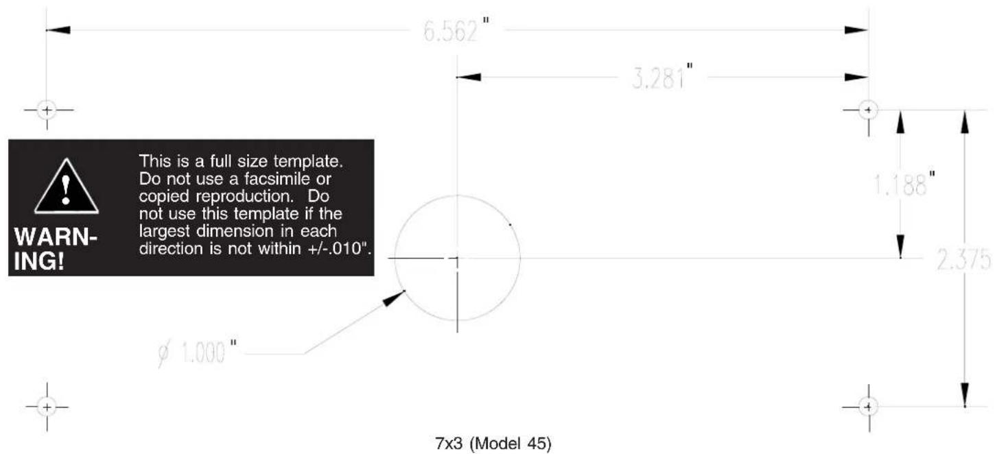
FIGURE 3

6x4 (Model 65)
FIGURE 4
Flash Pattern Selection
The LED Perimeter Lights are equipped with one steady burn and twenty flashing patterns including ten alternating patterns, an exclusive feature of the Code 3 LED Perimeter Light. All flash patterns are either 75 flashes per minute (FPM) or 150 FPM.
To select a different flash pattern, apply +12 or +24 VDC to the red wire and connect the black wire to the power supply ground. The unit will flash in whatever pattern was last set. Change the pattern by momentarily touching the white wire to the power supply ground. The flash pattern will change to the next pattern according to the following list:
| Pattern Number | Description |
| - Steady Burn | |
| 1 75 | FPM Single |
| 2 75 | FPM, Alternating Sides |
| 3 150 | FPM Single |
| 4 150 | FPM Single, Alternating Sides |
| 5 75 | FPM Double |
| 6 75 | FPM Double, Alternating Sides |
| 7 75 | FPM Triple |
| 8 75 | FPM Triple, Alternating Sides |
| 9 75 | FPM Quad |
| 10 75 | FPM Quad, Alternating Sides |
| 11 150 | FPM Quad |
| 12 150 | FPM Quad, Alternating Sides |
| 13 75 | FPM Hi-Low-Low-Hi |
| 14 75 | FPM Hi-Low-Low-Hi, Alternating Sides |
| 15 150 | FPM Double |
| 16 150 | FPM Double, Alternating Sides |
| 17 150 | FPM Triple |
| 18 150 | FPM Triple, Alternating Sides |
| 19 75 | FPM Hi-Low-Hi |
| 20 75 | FPM Hi-Low-Hi, Alternating Sides |
Continue to cycle through the various patterns until the desired pattern is selected. The unit will retain this pattern even when power is removed. Note: For Perimeter Lights the white flash pattern selection wire must be protected from contact with the system ground to prevent inadvertent changes to the flash pattern. This can be accomplished by sealing or capping the end of the wire.
For units that are flashed with an external control system such as a multiplexer or a flasher unit, the heads should be set to steady burn. Note: Regardless of the location in the program in the flash pattern list, the unit can be forced to steady burn by permanently electrically tying the white wire to the black wire.
It is recommended that all heads be set to the desired pattern at a workbench prior to installation.
Power Requirements
The Code3 LED Perimeter Lights are designed to be long life, full signal, light weight and low current draw. The following table lists the number of LEDs in each model and the average current draw for various conditions.
| Code 3 LED Perimeter Light Models | Number of LED's | Average Current Draw, Amps | |||
| Steady Burn 13.8VDC | Flashing 13.8VDC | Steady Burn 24.0VDC | Flashing 24VDC | ||
| Model 45,45STA&45STR 7x3 Perimeter | 62 | 1.0 | 0.5 | 0.5 | 0.3 |
| Model 65, 6x4 Perimeter | 76 | 1.0 | 0.5 | 0.5 | 0.3 |
| Model 85, 9x7 Perimeter | 124 | 1.5 | 0.8 | 0.8 | 0.4 |
| 65STR - 6x4, Red (Stop or Turn Config.) | 54 | 0.7 | 0.4 | 0.4 | 0.2 |
| 65STR - 6x4, Red (Tail Configuration) | 0.05 | n/a | 0.04 | n/a | |
| 65STA - 6x4, Amber Turn | 54 | 0.7 | 0.4 | 0.4 | 0.2 |
Parts & Exploded Views
Note: All of the components illustrated are for the 45 series. They are shown for reference only. The procedures outlined within are generic procedures and are for use in the 65 & 85 series as well.
| Standard Unit, Figure 4 Bezeled Unit, Figure 5 1 2 3 | 4 * 5 * | 6 * 7 | ||||||
| Code 3 Model Number - Description Code 3 Model Number - Description | Base Lens Lens O- Ring | Gasket | Bezel | Bezel Gasket | Bag of Screws | |||
| 45R - LED Perim, 7x3, Red | 45BZR - LED Perim, 7x3, Red, Bezel | - | T07891 | T07925 | T07919 | T07916 | T07922 | T07928 |
| 45A - LED Perim, 7x3, Amber | 45BZA - LED Perim, 7x3, Amber, Bezel - T07892 | |||||||
| 45B - LED Perim, 7x3, Blue | 45BZB - LED Perim, 7x3, Blue, Bezel | - | T07893 | |||||
| 45W - LED Perim, 7x3, White | 45BZW - LED Perim, 7x3, White, Bezel | -- | T07894 | |||||
| 45RB - LED Perim, 7x3, Red-Blue 45BZR | B - LED Perim, 7x3, Red-Blue - T07894 | |||||||
| 45RA - LED Perim, 7x3, Red-Amber | 45BZRAW - LED Perim, 7x3, Red-Amber | - | T07894 | |||||
| 45RW - LED Perim, 7x3, Red-White | 45BZRW - LED Perim, 7x3, Red-White | - | T07894 | |||||
| 45AW - LED Perim, 7x3, White-Amber | 45BZAW - LED Perim, 7x3, White-Amber | -- | T07894 | |||||
| 45STR - LED STT, 7x3, Red | 45STBZR - LED STT, 7x3, Red | - | T07895 | |||||
| 45STA - LED Turn, 7x3, Amber | 45STBZA - LED Turn, 7x3, Amber | - | T07896 | |||||
| 65R - LED Perim, 6x4, Red | 65BZR - LED Perim, 6x4, Red, Bezel | - | T07901 | T07926 | T07920 | T07917 | T07923 | |
| 65A - LED Perim, 6x4, Amber | 65BZA - LED Perim, 6x4, Amber, Bezel - T07902 | |||||||
| 65B - LED Perim, 6x4, Blue | 65BZB - LED Perim, 6x4, Blue, Bezel | - | T07903 | |||||
| 65W - LED Perim, 6x4, White | 65BZW - LED Perim, 6x4, White, Bezel | -- | T07904 | |||||
| 65RB - LED Perim, 6x4, Red-Blue 65BZR | B - LED Perim, 6x4, Red-Blue - T07904 | |||||||
| 65RA - LED Perim, 6x4, Red-Amber | 65BZRAW - LED Perim, 6x4, Red-Amber | - | T07904 | |||||
| 65RW - LED Perim, 6x4, Red-White | 65BZRW - LED Perim, 6x4, Red-White | - | T07904 | |||||
| 65AW - LED Perim, 6x4, Amber-White | 65BZAW - LED Perim, 6x4, Amber-White | - | T07904 | |||||
| 65STR - LED STT, 6x4, Red | 65STBZR - LED STT, 6x4, Red, Bezel | - | T07905 | |||||
| 65STA - LED Turn, 6x4, Amber | 65STBZA - LED Turn, 6x4, Amber, Bezel - T07906 | |||||||
| 85R - LED Perim, 9x7, Red | 85BZR - LED Perim, 9x7, Red, Bezel | - | T07911 | T07927 | T07921 | T07918 | T07924 | |
| 85A - LED Perim, 9x7, Amber | 85BZA - LED Perim, 9x7, Amber, Bezel - T07912 | |||||||
| 85B - LED Perim, 9x7, Blue | 85BZB - LED Perim, 9x7, Blue, Bezel | - | T07913 | |||||
| 85W - LED Perim, 9x7, White | 85BZW - LED Perim, 9x7, White, Bezel | -- | T07914 | |||||
* Gasket, item 4, only used for Standard Units.
Bezel, item 5, and Bezel Gasket, item 6, only used for Bezeled Units.
Turn Arrow Insert T04580 only used with 65STA.
Maintenance
The lens is field removable for cleaning or replacement. Remove the lens by unscrewing the four mounting screws. Use mild detergent, warm water and a soft cloth to clean both surfaces of the lens. Use of any other chemicals may void product warranty. Thoroughly dry before reinstalling.
Because plastic scratches easily, cleaning is only recommended when necessary. Do not subject the lenses to car washes that use brushes as these will scratch the lenses. Do not use a pressure washer.

Case Products
Cases of ten units, all the same. Add suffix letter K to the model number. For example, 45BZRK is a case of ten LED perimeter lights, 7 X 3, Red, Bezel.
65F 4x6 LED for Headlamp Housing (See figure 6 below)
1. Slip (4) tinnerman clips onto the four corners of the lower mounting bracket #S89856. 2. Attach the lens, gasket, and LED, to the mounting plate part #S95273. 3. Attach assembled LED assembly to the lower mounting bracket with screws through the tinnerman clips.


MOUNTING DIMENSIONS FOR 65STK3 4X6 LED PERIMETER TRIPLE STACK HOUSING

MOUNTING DIMENSIONS FOR 65STK4 4X6 LED PERIMETER QUAD STACK HOUSING

MOUNTING DIMENSIONS FOR 45STK3 3X7 LED PERIMETER TRIPLE STACK HOUSING
NOTES:
WARRANTY
Code 3, Inc. L.E.D. emergency warning devices are designed to exceed all industry standards and are tested and found to be operational at the time of manufacture. Provided they are installed and operated in accordance with manufacturer's recommendations, Code 3, Inc. guarantees all parts and components to a period of 1 year and the LED base unit for 5 years from the date of purchase or delivery, whichever is later. LED emergency warning devices which do not meet industry standards, within the warranty period, will be repaired or replaced, at Code 3 Inc.'s option, at the factory service center.
Use of inappropriate or inadequate wiring or circuit protection causes this warranty to become void. Failure or destruction of the product resulting from abuse or unusual use and/or accidents is not covered by this warranty. Code 3, Inc. shall in no way be liable for other damages including consequential, indirect or special damages whether loss is due to negligence or breach of warranty.
CODE 3, INC. MAKES NO OTHER EXPRESS OR IMPLIED WARRANTY INCLUDING, WITHOUT LIMITATION, WARRANTIES OF FITNESS OR MERCHANTABILITY, WITH RESPECT TO THIS PRODUCT.
PRODUCT RETURNS
If a product must be returned for repair or replacement*, please contact our factory to obtain a Return Goods Authorization Number (RGA number) before you ship the product to Code 3, Inc. Write the RGA number clearly on the package near the mailing label. Be sure you use sufficient packing materials to avoid damage to the product being returned while in transit.
*Code 3, Inc. reserves the right to repair or replace at its discretion. Code 3, Inc. assumes no responsibility or liability for expenses incurred for the removal and/or reinstallation of products requiring service and/or repair.; nor for the packaging, handling, and shipping: nor for the handling of products return to sender after the service has been rendered.
PROBLEMS OR QUESTIONS? CALL OUR TECHNICAL ASSISTANCE HOTLINE (314) 996-2800
Code 3,® Inc., a subsidiary of
Public Safety Equipment, Inc.
CODE 3®
PUBLIC SAFETY EQUIPMENT, INC.
Code 3, Inc.
10986 N. Warson Road
St. Louis, Missouri 63114-2029—USA
Ph. (314) 426-2700
Fax (314) 426-1337
www.code3pse.com


- SERIES
- LED PERIMETER, STOP/TURN/TAIL
- CONTENTS
- INTRODUCTION
- WARNING
- UNPACKING AND PRE-INSTALLATION
- MOUNTING OPTIONS
- INSTALLATION
- FLASH PATTERN SELECTION
- POWER REQUIREMENTS
- PARTS & EXPLODED VIEWS
- MAINTENANCE
- CASE PRODUCTS
- F 4X6 LED FOR HEADLAMP HOUSING (SEE FIGURE 6 BELOW)
- NOTES
- WARRANTY
- PRODUCT RETURNS
Brand : Code 3
Model : 65BZW
Category : Lighting