
RS62-EZ - Loudspeaker SoundTube - Free user manual and instructions
Find the device manual for free RS62-EZ SoundTube in PDF.


| Product Type | 2-Way In-Ceiling Speaker |
| Driver | 6.5" Polypropylene Woofer, 1" Silk Dome Tweeter |
| Power Handling | 100W RMS, 200W Peak |
| Impedance | 8 Ohms |
| Frequency Response | 50 Hz - 20 kHz |
| Sensitivity | 90 dB 1W/1m |
| Dimensions (Diameter x Depth) | 11.5" x 7.5" |
| Cutout Diameter | 10.5" |
| Weight | 5.5 lbs |
| Finish | White Paintable Grille |
| Mounting System | Patented EZ Mounting (Tool-Free) |
| Enclosure | Included Backcan |
| Input | Spring-Loaded Terminals |
| Safety Certifications | UL 2043 (Plenum Rated) |
| Warranty | 5 Years |
| Installation Accessories | Cutout Template, Mounting Screws |
| Cleaning | Wipe with Dry Cloth |
| Repairability | Replaceable Drivers and Grille |
Frequently Asked Questions - RS62-EZ SoundTube
User questions about RS62-EZ SoundTube
0 question about this device. Answer the ones you know or ask your own.
Ask a new question about this device
Download the instructions for your Loudspeaker in PDF format for free! Find your manual RS62-EZ - SoundTube and take your electronic device back in hand. On this page are published all the documents necessary for the use of your device. RS62-EZ by SoundTube.
USER MANUAL RS62-EZ SoundTube
Install Instructions For:
RS42-EZ-WH, RS42-EZ-BK, RS62-EZ-WH & RS62-EZ-BK

Box contents
1 Speaker
1 Cover Plate w/ 4 screws
1 Rubber weather plug
1 Hanging kit
1 3/8" NPT Wire Gland
1 3/4" to 3/8" NPT Adapter
1.435.647.9555 | 800.647.TUBE | www.soundtube.com
©2016 SoundTube Entertainment, Inc. All rights reserved. INS_RS-EZ 9-22-2016 - EN54 Document Reference Number RSEZ0013

WarningWarning
SoundTube speakers must be installed by a professional audio installer/contractor. For safety and for optimum audio performance, installer must follow all directions issued by SoundTube Entertainment.

Do not spec or install speaker near support beam, ventilation duct or other structure that may interfere with speaker function or dispersion.
RS-EZ series
Install Instructions For:
RS42-EZ-WH, RS42-EZ-BK, RS62-EZ-WH & RS62-EZ-BK
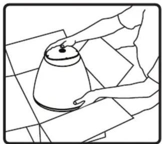
- Unpack speaker and SpeedClamp™ mounting hardware.
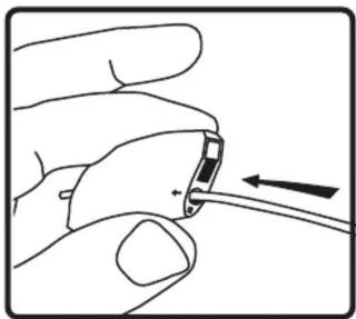
- Thread hanging or safety cable through SpeedClamp™ mechanisms as shown.

- Attach the hanging cable by securing it and safety cable to structure as shown.

- Thread cable end(s) through SpeedClamp™ mechanisms as shown.

- Adjust speaker hanging height with SpeedClamp™ mechanism. Pull to tighten & press button on SpeedClamp as shown to loosen or adjust.
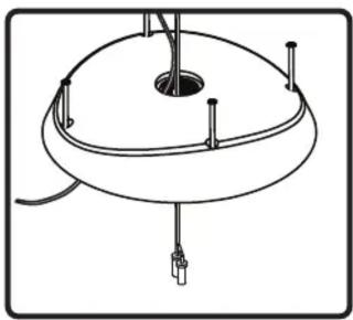
- Slide cover plate over hanging and safety cables and run signal wire through center hole.

7a. Attach hanging cable by (1) inserting into side of mounting bracket and (2) rotating to align with center slot in hanging bracket.
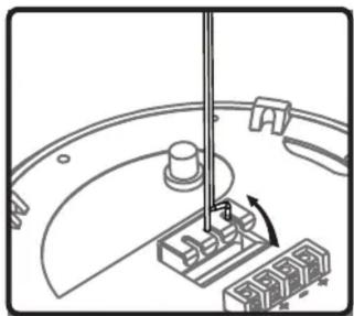
7b. Once aligned with central slot, pull cable up into slot to secure. Repeat steps 7a and 7b with secondary safety cable into one of the side slots.

- Extra slot and 2 holes provided for additional safety cables where needed.
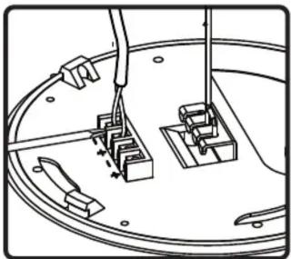
- Connect signal wires to (+) and (-) inputs. Use extra (+) and (-) for daisy chaining.

- Select desired tap position. Switch is preset to maximum 70.7V (100V) mode.

- Place cover plate onto top of speaker and rotate clockwise until alignment indicators meet.

- Tighten all four (4) screws to lock cover plate in place.

- Install rubber weather plug by sliding slit over the wire, then pressing snuggly into hole in cover plate.
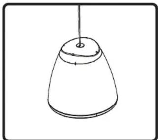
- Done.
RS-EZ series
Install Instructions For:
RS42-EZ-WH, RS42-EZ-BK, RS62-EZ-WH & RS62-EZ-BK
Note: Conduit is not an approved mounting method for UL1480 installations
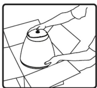
- Unpack speaker from box.

- Securely mount conduit to structure. Conduit must have 3/4" NPT thread to accomodate RS-EZ speaker.

- Thread cover plate on to conduit until secure.

- Run signal wire and at least one safety cable through conduit.
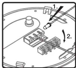
- Attach safety cable by first inserting into side of mounting bracket.
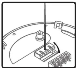
- Align safety cable with center slot and pull up to secure.
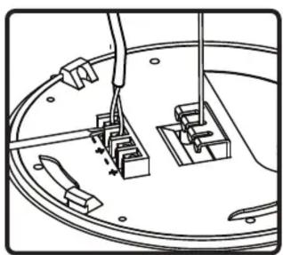
- Connect signal wires to (+) and (-) inputs. Use extra (+) and (-) for daisy chaining.
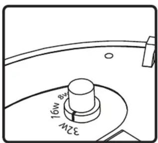
- Select desired tap position. Switch is preset to maximum 70.7V (100V) mode.
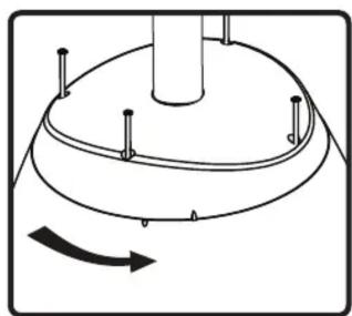
- Line speaker up with cover plate and rotate to lock in to place. Alignment marks will meet when secured.

- Tighten all four (4) screws 11. Done. to lock speaker in to cover plate.
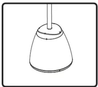
EN54-24
Install Instructions For EN54-24 Compliance
In order for this speaker to be EN54-24 compliant, a 3/8" NPT wire gland and a 3/4" to 3/8" NPT adapter have been included with the product. These items must be installed according to this document to be EN54-24 compliant.

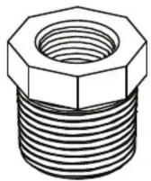
3/8" NPT Wire Gland 3/4" to 3/8" NPT Adapter
Installation

- Thread the 3/4" to 3/8" NPT adapter into the top plate of the speaker in the hole provided. Make sure to tighten securely to ensure a water tight fit.
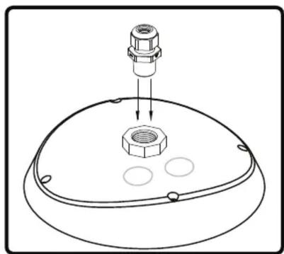
- Thread the 3/8" NPT wire gland into the 3/4" to 3/8" NPT adapter. Make sure to tighten securely to ensure a water tight fit.
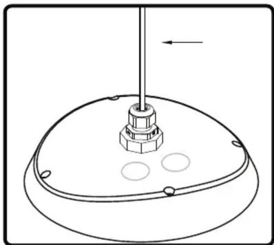
- Thread the speaker security cable through the 3/8" NPT wire gland and attach to the back of the speaker as noted in the installation instructions.
Tighten the top of 3/8" NPT wire gland such that the rubber grommet is tight around the cable. This may require a wrench.
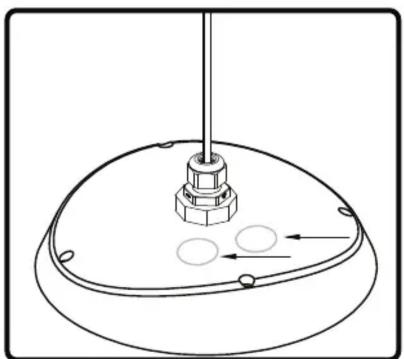
- Thread signal wires through the provided conduit knockouts.
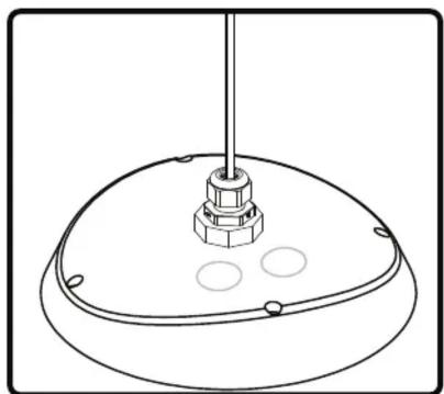
- Done
Note: A water tight conduit connection must be used in the knockout locations in order to be EN54-24 compliant
Brand : SoundTube
Model : RS62-EZ
Category : Loudspeaker