
Omada EAP110 V4 - Access Point TP-LINK - Free user manual and instructions
Find the device manual for free Omada EAP110 V4 TP-LINK in PDF.


| Type of product | Access Point |
| Brand | TP-Link |
| Model | Omada EAP110 V4 |
| Wireless standard | IEEE 802.11n |
| Frequency band | 2.4 GHz |
| Maximum data rate | 300 Mbps |
| Ethernet ports | 1x 10/100 Mbps (PoE input) |
| Power supply | PoE (802.3af) or passive PoE |
| Mounting | Ceiling / Wall (kit included) |
| Dimensions | 150 x 150 x 30 mm |
| Weight | 200 g |
| Operating temperature | 0°C to 40°C |
| Security | WPA/WPA2-PSK, WPA-Enterprise |
| Management | Omada Controller (cloud or local) |
| LED indicators | Power, LAN, WLAN |
| Antenna | 2 internal omnidirectional |
| Firmware upgrade | Via Omada Controller or web interface |
| Cleaning | Wipe with a soft dry cloth |
| Spare parts | Not applicable (no user-serviceable parts) |
Frequently Asked Questions - Omada EAP110 V4 TP-LINK
User questions about Omada EAP110 V4 TP-LINK
0 question about this device. Answer the ones you know or ask your own.
Ask a new question about this device
Download the instructions for your Access Point in PDF format for free! Find your manual Omada EAP110 V4 - TP-LINK and take your electronic device back in hand. On this page are published all the documents necessary for the use of your device. Omada EAP110 V4 by TP-LINK.
USER MANUAL Omada EAP110 V4 TP-LINK
1.1 Determine the Network Topology ....2
1.1.1 Management on the local Network....2 1.1.2 Management via Cloud Access....4
1.2 Install Omada Controller Software....5
1.2.1 Installation on Windows Host....5 1.2.2 Installation on Linux Host .... 5
1.3 Inform the EAPs of the Controller Host's Address....7
1.4 Start and Log In to the Omada Controller 8
1.4.1 Launch Omada Controller 9 1.4.2 Do the Basic Configurations....9 1.4.3 Log In to the Management Interface.... 12
1.5 Create Sites and Adopt EAPs....13
1.5.1 Create Sites.... 13 1.5.2 Adopt the EAPs 16
1.6 Monitor and Manage the EAPs....17
2 Monitor and Manage the Network....18
2.1 View the Statistics of the Network....19
2.1.1 View the Client Distribution on SSID 19 2.1.2 Have a Quick Look at EAPs and Clients 19 2.1.3 View Current Usage-Top EAPs 20 2.1.4 View Recent Activities 20
2.2 Monitor the Network with the Map 21
2.2.1 Add a Map.... 21 2.2.2 Monitor the EAPs on the Map 24
2.3 Monitor and Manage the EAPs....25
2.3.1 Manage the EAPs in Different Status.... 25
2.3.2 View the Detailed Information of EAPs.... 26 2.3.3 Manage the EAPs in the Action Column 26
2.4 Monitor and Manage Clients....28
2.4.1 View the Current Information of Clients 28 2.4.2 Manage Clients in the Action Column.... 28
2.5 View Clients Statistics During the Specified Period 29
2.5.1 Select a Specified Period 29 2.5.2 View the History Information of Clients 30 2.5.3 Manage Clients in the Action Column.... 30
2.6 Manage the Rogue APs List 30
2.6.1 Manage the Untrusted Rogue APs List 31 2.6.2 Manage the Trusted Rogue APs List.... 31
2.7 View Past Guest Authorization....32
2.8 View Logs....32
3 Configure the EAPs Globally....34
3.1 Wireless Network....35
3.1.1 Add Wireless Networks.... 35 3.1.2 Configure Advanced Wireless Parameters 45 3.1.3 Configure Band Steering 47 3.1.4 Configure Mesh....48
3.2 Access Control 53
3.3 Portal Authentication....54
3.3.1 No Authentication....55 3.3.2 Simple Password 59 3.3.3 Local User....63 3.3.4 Voucher....71 3.3.5 SMS....78 3.3.6 Facebook....83 3.3.7 External RADIUS Server 84
3.3.8 External Portal Server 90
3.4 Free Authentication Policy....91
3.5 MAC Filter 92
3.6 Scheduler....94
3.7 QoS....96
3.8 Site Settings 99
3.8.1 LED 99
3.8.2 Device Account....100
3.8.3 Reboot Schedule....100
3.8.4 Log Settings 101
3.8.5 Batch Upgrade....102
3.8.6 SSH....104
3.8.7 Management VLAN....105
4 Omada Cloud Service.... 106
4.1 Configure the Cloud Access.... 107
4.1.1 Enable Cloud Access....107
4.1.2 Manage the Cloud Users 107
4.2 Manage the Controller via Omada Cloud 109
4.2.1 Access the controller via Omada Cloud....110
4.2.2 Change your TP-Link ID information....112
5 Configure the EAPs Separately 113
5.1 View the Information of the EAP.... 114
5.1.1 Active Channel Information....114
5.1.2 Overview....115
5.1.3 LAN....115
5.1.4 Radio....116
5.2 View Clients Connecting to the EAP 116
5.2.1 User....116
5.2.2 Guest....117
5.3 View Mesh Information of the EAP 117
5.3.1 Uplinks 117 5.3.2 Downlinks 118
5.4 Configure the EAP 118
5.4.1 Basic Config....118 5.4.2 IP Setting....119 5.4.3 Radio....120 5.4.4 Load Balance....121 5.4.5 WLANs....122 5.4.6 LED 122 5.4.7 Trunk Settings (Only for EAP330)....123 5.4.8 Rogue APs Detection....123 5.4.9 Local LAN Port Settings (Only for EAP115-Wall and EAP225-Wall) 124 5.4.10 Forget this AP 124
6 Manage the Omada Controller 125
6.1 User Account.... 126 6.2 General Setting.... 127
6.2.1 Configure Controller Name....127 6.2.2 Configure Mail Server 127
6.3 History Data Retention.... 129 6.4 Backup&Restore....130 6.5 Auto Backup.... 130 6.6 Migrate....133
6.6.1 Controller Migrate 133 6.6.2 Site Migrate....137
6.7 Information About the Software.... 141
7 Application Example 142
7.1 Basic Configuration.... 143 7.2 Advanced Settings 143
7.2.1 Monitor the EAPs with Map....143 7.2.2 Configure Portal Authentication....144 7.2.3 Create a SSID for the Employees....146 7.2.4 Configure Scheduler....147
Appendix: Omada App 149
1 Install Omada App on the Mobile Device 150 2 Manage your Network in Standalone Mode 150 3 Manage your Network in Controller Mode.... 153 3.1 Locally manage your EAPs using the Omada App 153 3.2 Remotely manage your EAPs using the Omada App 156
1 Quick Start
Omada Controller is a management software for TP-Link EAPs. With this software, you can centrally manage your EAPs, such as configure EAPs in batches and conduct real-time monitoring of EAPs locally or remotely through Omada Cloud service.
Follow the steps below to complete the basic settings of Omada Controller.
- Determine the Network Topology
- Install Omada Controller Software
- Inform the EAPs of the Controller Host's Address
- Start and Log In to the Omada Controller
- Create Sites and Adopt the EAPs
- Monitor and Manage the EAPs
1.1 Determine the Network Topology
There are two methods to centrally manage EAPs via Omada Controller:
■ Management on the Local Network ■ Management via Cloud Access
Determine your management method according to your need and refer to the following introductions to build your network topology.
Tips:
Omada app offers a convenient way to access the Omada Controller and adopt EAPs. With Local Access and Cloud Access functions on the Omada app, you can manage the controller at local and remote sites. For more detailed information about the Omada app, refer to Appendix: Omada App.
1.1.1 Management on the Local Network
There are two kinds of network topologies to centrally manage EAPs on the local network:
■ Omada Controller and EAPs are in the same subnet. ■ Omada Controller and EAPs are in different subnets.
Determine your management method according to your need and refer to the following introductions to build your network topology.
Management in the Same Subnet
If your Omada Controller and EAPs are in the same subnet, refer to the following network topology.
A router acts as a DHCP server to assign IP addresses to EAPs and clients. The Omada Controller should be installed on one host, which is called the Controller Host. Other hosts in the same LAN can access the Controller Host to manage the network. Taking the following topology as an example, you can enter "https://192.168.0.100:8043" in a web browser on Host B to visit the Omada Controller interface on Host A. It is recommended to set a static IP address for the Controller Host for convenient login to the Omada Controller interface.
![graph TD A["Omada Controller"] --> B["Layer 2 Switch"] B --> C["Router (DHCP Server) LAN IP:192.168.0.1/24"] B --> D["Host B"] B --> E["EAPs"] B --> F["Clients"] G["Internet"] --> H["Client"] style A fill:#f9f,stroke:#333 style B fill:#ccf,stroke:#333 style C fill:#cfc,stroke:#333 style D fill:#fcc,…](/content/2026/06/1336671/images/f969d7dbb6b69fdb286602064a4d6ac3d93702ea05794f75506aa1c24b035771.jpg)
Note:
- The Omada Controller must be running all the time when you manage the network.
- The Omada Controller can be running on only one host in a LAN. When other users in the LAN try to launch the Omada Controller on their own hosts, they will be redirected to the host that is already running the Omada Controller.
Management in Different Subnets
If your Omada Controller and EAPs are in different subnets, refer to the following topology.
A router acts as the gateway of the network. A layer 3 switch acts as a DHCP server to assign IP addresses to EAPs and clients. The Controller Host and the EAPs are connected to the switch's different network segments. To help EAPs find the Controller Host, the Omada Discovery Utility should be installed on Host B, which is in the same subnet as the EAPs. For how to use the Omada Discovery Utility, refer to "Inform the EAPs of the Controller Host's Address".
![graph TD A["Omada Controller"] -->|192.168.1.0/24| B["Layer 3 Switch (DHCP Server)"] B -->|192.168.2.0/24| C["Omada Discovery Utility"] B --> D["Host B"] B --> E["EAPs"] B --> F["Internet"] G["Client"] --> H["Mobile Device"] G --> I["Smartphone"] G --> J["Laptop"] B --> K["Router"] K --> L["WAN"] st…](/content/2026/06/1336671/images/044848d85dbb1540b2b1f1d4eae5e8d4b1400a55d6c7d1efc0838c8bf1855d8b.jpg)
1.1.2 Management via Cloud Access
With Cloud Access enabled on the Omada Controller, you can use https://omada.tplinkcloud.com to remotely access and monitor multiple controllers. If you want to manage EAPs remotely via Omada Cloud, refer to the following topology.
A router acts as the gateway of the network. A Layer 3 switch acts as a DHCP server to assign IP addresses to EAPs and clients. The management device is not on the local network. On the management device, you can launch a web browser to remotely launch Omada Controller to manage EAPs via Omada Cloud. For more details about Cloud Access, refer to Omada Cloud Service.
![graph TD A["Switch"] --> B["LAN"] B --> C["Router"] C --> D["Internet"] D --> E["Management Devices"] F["Omada Controller"] --> G["Controller Host"] H["Mobile Device"] --> I["Client"] J["Smartphone"] --> K["Client"] L["Client"] --> M["EAPs"] N["Wireless Signal"] --> O["Wireless Signal"] P["Wireless…](/content/2026/06/1336671/images/90a156de614103b8cbe8b43ec8fba10f0b50a40778c9fe1d3597f3034091a5fc.jpg)
1.2 Install Omada Controller Software
We provide Omada Controller for both Windows and Linux operating systems. Determine your operation system and follow the introductions below to install Omada Controller.
1.2.1 Installation on Windows Host
Make sure your PC meets the following requirements of hardware and system, then properly install the Omada Controller software.
Hardware Requirements
Omada Controller can manage up to 1500 EAPs if the Controller Host has enough hardware resources. To guarantee operational stability for managing 1500 EAPs, we recommend that you use the hardware which meets or exceeds the following specifications:
CPU: Intel Core i3-8100, i5-6500, or i7-4700 with 2 or more cores and 4 or more threads.
Memory: 6 GB RAM or more.
System Requirements
Operating System: Microsoft Windows 7/8/10/Server.
Web Browser: Mozilla Firefox 32 (or above), Google Chrome 37 (or above), Opera 24 (or above), or Microsoft Internet Explorer 11 (or above).
Note:
We recommend that you deploy Omada Controller on a 64-bit operating system to guarantee the software stability.
Install Omada Controller
Download the installation file of Omada Controller from the website https://www.tp-link.com/en/download/EAP-Controller.html. Then follow the instructions to properly install the Omada Controller software. After successful installation, a shortcut icon of the Omada Controller will be created on your desktop.
1.2.2 Installation on Linux Host
Two versions of installation package are provided: .tar.gz file and .deb file. The .tar.gz file can be used in multiple versions of Linux operating system. And the .deb file can be used in Ubuntu and Debian.
Make sure your PC meets the following requirements of hardware and system, then choose the proper installation files to install the Omada Controller software.
Hardware Requirements
Omada Controller can manage up to 1500 EAPs if the Controller Host has enough hardware resources. To guarantee operational stability for managing 1500 EAPs, we recommend that you use the hardware which meets or exceeds the following specifications:
CPU: Intel Core i3-8100, i5-6500, or i7-4700 with 2 or more cores and 4 or more threads.
Memory: 6 GB RAM or more.
System Requirements
Operating System: 64-bit Linux operating system, including Ubuntu 14.04/16.04/17.04, CentOS 6.x/7.x, Fedora 20 (or above) and Debian 9.8.
Web Browser: Mozilla Firefox 32 (or above), Google Chrome 37 (or above), Opera 24 (or above), or Microsoft Internet Explorer 11 (or above).
Install the Omada Controller
Download the installation file of Omada Controller from our website https://www.tp-link.com/en/download/EAP-Controller.html.
Make sure you have jsvc and curl installed in your system before installation, which is vital to the smooth running of the system. If your system does not have jsvc or curl installed, you can install it manually with the command: apt-get install or yum install. For example, you can use the command: apt-get install jsvc or yum install jsvc to get jsvc installed. And if dependencies are missing, you can use the command: apt-get -f install to fix the problem.
■ Install the .tar.gz file
Follow the steps below to install Omada Controller on your Linux PC:
- Make sure your PC is running in root mode. You can use this command to enter root mode: sudo
- Extract the tar.gz file using the command: tar zxvf Omada_Controller_v3.0.5_linux_x64_targz.tar.gz
- Install Omada Controller using the command: sudo./install.sh
■ Install the .deb file
Follow the steps below to install Omada Controller on your Linux PC:
- Make sure your PC is running in root mode. You can use this command to enter root mode:
sudo
- Install the .deb file using the command:
dpkg -i Omada_Controller_v3.0.5_linux_x64.deb
Tips:
- For installing the .tar.gz, if you want Omada Controller to run as a user (it runs as root by default), you should modify the OMADA_USER value in bin/control.sh.
- To uninstall Omada Controller, go to the installation path: /opt/tplink/EAPController, and run the command: sudo ./uninstall.sh.
- During uninstallation, you can choose whether to backup the database. The backup folder is /opt/tplink/eap_db_backup.
- During installation, you will be asked whether to restore the database if there is any backup database in the folder /opt/tplink/eap_db_backup.
1.3 Inform the EAPs of the Controller Host's Address
If your Controller Host and EAPs are in the same network segment, you can skip this section.
If your Controller Host and EAPs are in different subnets, you need to install Omada Discovery Utility on a host that is in the same network segment with the EAPs. Omada Discovery Utility can help EAPs find the Controller Host.
System Requirements
Windows 7/8/10/Server
Mac OS X 10.7/10.8/10.9/10.10/10.11
Install and Use Omada Discovery Utility
Follow the steps below to install Omada Discovery Utility and use it to inform the EAPs of the Controller Host's IP address:
- Download the installation file with the latest version from the website https://www.tp-link.com/en/download/EAP-Controller.html#EAP_Discovery_Tool.
- Make sure you have JRE (Java Runtime Environment) with version 1.8 installed on your system before installation. If your system loses JRE, download JRE from the website https://www.oracle.com/technetwork/java/javase/downloads/jre8-downloads-2133155.html and install it on your system.
- For Windows OS, run the start-omada-discovery-utility.bat to open the Omada Discovery Utility. For Mac OS, use the command java -jar ** to open the Omada Discovery Utility. Then the following window will pop up. This window shows the information of all EAPs in the same LAN.

- Click Manage in the Action column or select multiple EAPs and click Batch Setting.
- Enter the hostname or IP address of the Controller Host.
- Enter the EAP's username and password (both are admin by default).

- Click Apply to inform the EAP of the Controller Host's hostname or IP address. And then the connection can be established between the EAP and the Controller Host.
1.4 Start and Log In to the Omada Controller
Launch Omada Controller and follow the instructions to complete the basic configurations, and then you can log in to the management interface.
1.4.1 Launch Omada Controller
Double click the icon and the following window will pop up. You can click Hide to hide this window but do not close it. After a while, your web browser will automatically open.

Note:
- If your browser does not open automatically, click Launch a Browser to Manage Wireless Network. You can also launch a web browser and enter http://127.0.0.1:8088 in the address bar. • If your web browser opens but prompts a problem with the website's security certificate, click Continue.
- Only one Omada Controller can run in a LAN. If an Omada Controller has already been running on a host that is in your LAN, you will be redirected to the Omada Controller interface on that host.
1.4.2 Do the Basic Configurations
In the web browser you can see the configuration page. Follow the setup wizard to complete the basic settings for Omada Controller.
1. Click Let's Get Started.
Welcome to use Omada Controller
Please follow the wizard to set up your Controller.
Let's Get Started
- Specify a name for Omada Controller. Click Next.

- Specify a username and password for the login account. Specify the email address for resetting your password in case that you forget the password. After logging in Omada Controller, set a mail server so that you can receive emails and reset your password. For how to set a mail server, refer to Configure Mail Server. Click Next.

- The setup page displays all the detected EAPs in the network. Select one or more EAPs to be managed and click Next.

- Set an SSID name (wireless network name) and password for the EAPs to be managed. Omada Controller will create two wireless networks, a 2.4GHz one and a 5GHz one, both encrypted in WPA2-PSK mode. Click Next.

- If you want to manage EAPs via Omada Cloud, enable the Cloud Access button, and bind your TP-Link ID to your Omada Controller, and then click Next. If you want to manage EAPs on the local network, you can just click Skip. For more details about Omada Cloud, please refer to Omada Cloud Service in chapter 4.

- Review your settings and click Finish.

1.4.3 Log In to the Management Interface
Once the basic configurations are finished, the browser will be redirected to the following page. Log in to the management interface using the username and password you have set in the basic configurations.
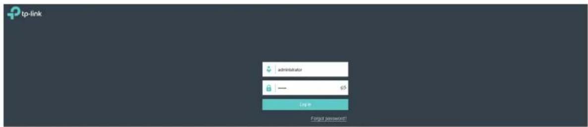
Note:
In addition to the Controller Host, other hosts in the same LAN can also manage EAPs via remote access to the Controller Host. For example, if the IP address of the Controller Host is 192.168.0.100 and Omada Controller is running normally on this host, you can enter https://192.168.0.100:8043/login, or https://192.168.0.100:8043, or http://192.168.0.100:8088 in the web browser of other hosts in the same LAN to log in to the Omada Controller and manage EAPs. Or you can log in to Omada Controller on the management devices through Omada Cloud service.
1.5 Create Sites and Adopt EAPs
Omada Controller can manage multiple EAP networks, which are called sites. Multiple sites are logically separated, and each site has its own configurations. There is an initial site named Default. The Default site cannot be deleted. If you have no need to manage EAPs with different sites, you can edit the default site and skip the Create Sites section. However, Adopt the EAPs is a necessary step to manage the EAPs.
1.5.1 Create Sites
There are three methods to create sites: Add Sites, Import Sites, and Copy Sites. Determine the method according to your need and refer to the following introductions to create sites.
Add Sites
Follow the steps below to add a new site directly.
- Click Sites: Default in the top left corner of the page and select Site Manager, the following window will pop up.

- Click and enter a unique name for the new site.
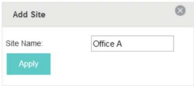
- Click Apply to create the site.
Import Sites
You can import the site from another controller. The site settings and EAPs in the site will be imported to the new site.
Note:
- The site to be imported must come from a different controller.
- Importing sites is available only for local logged-in users.
- Click Sites: Default in the top left corner of the page and select Site Manager, and then the following window will pop up.

- Click and enter a unique name for the new site.
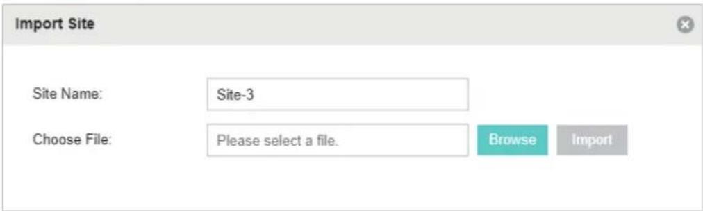
- Click Browse to upload the backup file of another site and click Import to import the site.

Tips:
To export sites (including site settings and EAPs in the sites) from one controller to another, use the Migrate function. For more details about Migrate, refer to Migrate.
Copy Sites
With Site Copy, you can create a new site with the same settings as the existing sites on your controller. Note that only the site settings will be copied. The EAPs will still be managed at the original site.
- Click Sites: Default √ in the top left corner of the page and select, a small number in the following window will pop up.
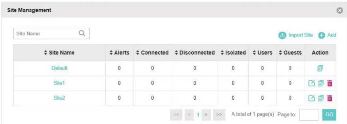
- Select a site that you want to copy all the settings and click in the Action column. Then enter a unique name for the new site.
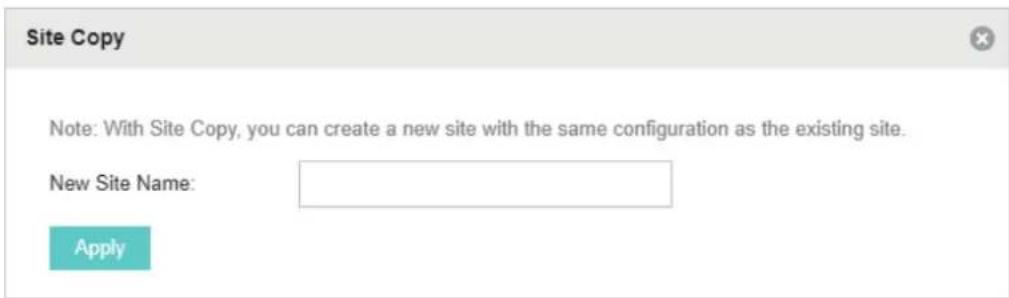
- Click Apply to create the site.
1.5.2 Adopt the EAPs
Omada Controller can discover all EAPs currently connected in the network and display their connection status. All EAPs are in Pending status when first discovered by Omada Controller. To manage the EAPs, you need to adopt them. In the quick setup process, Omada Controller will automatically adopt the selected EAPs using the default username and password (both are admin). However, if you have changed the username or password of your EAPs before, Omada Controller cannot automatically adopt them, and you need to refer to the following steps to adopt them manually.
To ensure that all EAPs are adopted, follow the steps below:
- Select a site and go to Access Points > Pending. The table displays all the EAPs that have not been adopted.

- Click the Retry button in the Action column and enter the current username and password of the EAP. Click Apply.

Tips:
- If you have a new discovered EAP, you can click the Adopt button in the Action column to adopt the EAP. Omada Controller will automatically adopt the EAP using the default username and password (both are admin).
- If you have multiple newly discovered EAPs, and all of them have the default username and password (both are admin), you can click the Batch Adopt button to adopt them in batch. But if there are any EAPs with the Retry button, it means that the username and password of these EAPs have been changed. You need to first adopt them before batch adopting the rest of the EAPs.
- After EAPs are adopted, the status will change from Pending to Connected. All the EAPs' username and password will become the same as those of the Controller's administrator account you created in the Basic Configuration.
Tips:
If you want to change the EAPs' username and password, refer to Device Account.
1.6 Monitor and Manage the EAPs
When all the configurations above are finished, you can centrally monitor and manage the EAPs via the Omada Controller's management interface. The management interface is divided into three sections as the following figure shows.

Section A
In Section A, you can check the status of EAPs and clients in the network. Also, you can click 📊 to refresh the current page, click 🔒 to globally configure the wireless network, and click ➤ to sign out from the management interface.
Furthermore, the Sites allows you to group your EAPs and manage them in batches. To configure sites, refer to Create Sites.
Section B In Section B, you can centrally monitor the EAPs and clients.
Section C
In Section C, you can globally configure the wireless network. The global configurations will take effect on all the adopted EAPs.
2 Monitor and Manage the Network
With Omada Controller you can monitor the EAPs and centrally manage your wireless network. This chapter includes the following sections:
■ View the Statistics of the Network ■ Monitor the Network with the Map ■ Monitor and Manage the EAPs ■ Monitor and Manage Clients ■ View Clients Statistics during the Specified Period ■ Manage the Rogue APs List ■ View Past Guest Authorization ■ View Logs
2.1 View the Statistics of the Network
Omada Controller collects all statistics of the managed EAPs and displays the statistical information via graphs, pie charts and tables, providing an overview of your wireless network.

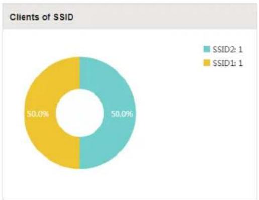
2.1.1 View the Client Distribution on SSID
A visual pie chart shows the client distribution on each SSID. For example, the SSID1 has one client, which occupies 50% of all the clients.
2.1.2 Have a Quick Look at EAPs and Clients
This tab displays the Most Active AP, the Most Active Clients and the All-Time Top Client. You can click the MAC address of the EAP or the client to see more details.

Most Active AP: The current connected AP with the maximum traffic.
Most Active Client: The current connected client with the maximum traffic.
All-time Top Client: The client with the maximum traffic among all the clients that have ever accessed the EAP network.
2.1.3 View Current Usage-Top EAPs
This tab lists the number of connected clients and the data traffic condition of the ten APs that use the most traffic currently.

Clients: The amount of clients connected to this EAP.
| %Clients | The proportion of current connected clients to the Top EAPs' total client amount. |
| Traffic (MB) | The total amount of data transmitted by this EAP, which equals the sum of the transmission traffic of all the current clients that connect to the AP. |
| %Traffic | The proportion of the EAP's current data transmission amount to the Top EAPs' total transmission amount. |
2.1.4 View Recent Activities
The Recent Activities statistics can be toggled between a view for the past specific 24 hours and one for the past specific 30 days.
The left ordinate axis indicates the traffic and the right one represents the number of the clients. The abscissa axis shows the selected time period. Traffic indicates a visual graph of the network
traffic during the selected time period. Client indicates a visual graph of the number of the connected clients during the selected time period. For example, the statistics information at 15:00 indicates the traffic size and client number from 14:00 to 15:00. In the following figure, at 11 o'clock, the traffic is about 34MB and there is 1 client connected to the AP.

2.2 Monitor the Network with the Map
You can upload your local map images and monitor the status and coverage range of each EAP with the map. When you initially launch Omada Controller, a default map is displayed as the following figure shows. Follow the instructions below to add your own map and manage the EAPs via the map.

2.2.1 Add a Map
Prepare a map image in .jpg, .jpeg, .gif, .png, .bmp, .tiff format. And then follow the steps below to add the map to the Omada Controller.
- Click Configure Maps on the upper right corner of the Map page and click Add.

- Enter the map description, select your map image, and click Create.

- Select your local map from the drop-down list on the upper right corner of the map area.

- Click 1. Draw a line on the map and enter the distance the line represents. Then the Omada Controller will compute and generate the map scale automatically based on your configuration.

- Drag the EAPs from the Unplaced APs list to the appropriate locations on the map according to their actual locations.

You can click to reveal additional options:

| Lock the selected EAP in the current location on the map. | |
| Unlock the selected EAP and you can drag it to another location. | |
| Display the EAP's details and configure the wireless parameters. Refer to Configure the EAPs Separately. | |
| Remove the selected EAP back into the Unplaced APs list. | |
| Flash the LED of the EAP on the map. Then the LED will flash for 10 minutes or until the cancel button is clicked again. | |
| Click the button to stop the LED from flashing. |
2.2.2 Monitor the EAPs on the Map
Click any of the following options to display EAP Label, Details, and Coverage on the map.
Label | Details | Coverage
| Label Display the EAP's name. The default name is the MAC address of the EAP. | |
| Details | Display the EAP's name, MAC address, IP address, transmitting/receiving channel, number of connected users, and number of connected guests. |
| Coverage | Display a visual representation of the wireless range covered by EAPs. The actual signal coverage may be smaller than the visual coverage on the map because the obstacles around the EAPs will weaken the signal. |
2.3 Monitor and Manage the EAPs
Omada Controller can discover all the EAPs currently connected to the network and display their information on the Access Points page.

2.3.1 Manage the EAPs in Different Status
According to their connection status, EAPs are divided into four categories: Connected, Disconnected, Isolated, and Pending. You can view the EAPs in different status on different pages:

| All Displays the information of all EAPs in different status. | |
| Connected | Displays the connected EAPs.The status of connected EAPs includes two cases: Connected and Connected (Wireless).Connected: After you adopt a wired EAP in Pending status, its status will become Provisioning, then Configuring and Connected eventually-connected (Wireless): In a mesh network, if an EAP has a successful wireless uplink, its status will become Adopting (Wireless) and then Connected (Wireless).Only connected EAPs can be managed. A connected EAP will turn into a pending one after you forget it. You can refer to Forget this AP to forget an EAP or click Forget All on the page to forget all the connected EAPs. |
| Disconnected | Displays the disconnected EAPs.If a connected EAP powers off or disconnects from the Omada Controller, it will be in Disconnected status. When a disconnected EAP is reset to factory defaults or forgot, it will turn into a pending one again. You can refer to Forget this AP to forget a EAP or click Forget All on the page to forget all the disconnected EAPs. |
| Isolated | Displays the isolated EAPs.In a mesh network, when the EAP which has been managed before by Omada Controller connects to the network wirelessly and cannot reach the gateway, it goes into the Isolated state. The isolated EAP searches for wireless uplink and the LED on the device turns green and flashes off every 5 seconds. To know more about mesh network, refer to Configure Mesh. |
Pending: Displays the pending EAPs.
The status of pending EAPs includes three cases: Pending, Pending (Wireless), and Managed by others.
Pending: All the EAPs with wired network connection are in pending status by default when first discovered by Omada Controller.
Pending (Wireless): The factory default EAP with mesh functions and no wired network connection is in Pending (Wireless) status when first discovered by Omada Controller.
Managed by others: An EAP is located on the same network as the controller, but has been already managed by an existing controller before. You can provide the username/password to unbind the EAP from the existing controller and begin adoption in current controller.
Only after pending EAPs are adopted and connected, can you manage them. To adopt pending EAPs, refer to Adopt the EAPs.
2.3.2 View the Detailed Information of EAPs
You can click Overview, Config, Performance, or Mesh Network tab to view different detailed information of EAPs.
| Overview | Config | Performance | Mesh Network | |
| Overview | Displays the EAP's name, MAC address, IP address, status, model, hardware version, firmware version, channel number of connected clients and download/upload bytes. | |||
| Config | Displays the EAP's name, MAC address, IP address, status, model, hardware version, firmware version, WLAN Group bounded with the 2G and 5G of the EAP, and radio of the 2G and 5G. | |||
| Performance | Displays the EAP's name, MAC address, IP address, status, model, hardware version, firmware version, number of connected 2G clients and 5G clients, TX(Downloaded Traffic), RX(Uploaded Traffic), TX 2G and TX 5G. | |||
| Mesh Network | Displays the EAP's name, MAC address, IP address, status, model, hardware version, firmware version, number of connected clients, hops, uplink APs and downlink APs. | |||
2.3.3 Manage the EAPs in the Action Column
You can execute the corresponding operation to the EAP by clicking an icon in the Action column.

| Locate the EAP in the map. | |
| Reboot the EAP. |

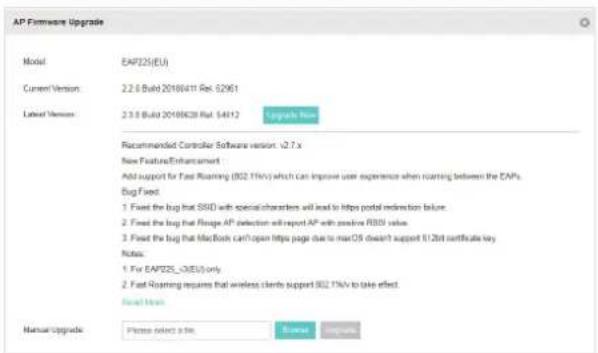
Upgrade the EAP.
Two options are available for upgrading: upgrade online and upgrade manually.
Upgrade online: With Cloud Access enabled on the controller and a TP-Link ID bound with the controller, the latest firmware for the EAP can be detected by the controller automatically. And you can upgrade the EAP online by clicking Upgrade Now. For more details about Cloud Access, refer to Omada Cloud Service.
Upgrade manually: Click Browse to locate and choose the upgrade file in your computer, then click Upgrade to install the latest EAP firmware. The Status will appear as Upgrading until the process is complete and the EAP reconnects to the Omada Controller.

Move the EAP to a site.
Select a site that has been created and click Apply. You can group all the EAPs by this way and centrally manage them on each site.


Configure the EAP.
For detailed instructions about how to configure the EAP on this window, refer to Configure the EAPs Separately.

Note:
- Only managed EAPs can be rebooted or upgraded.
- The EAP which is managed by the controller can not be logged in to its own management interface. To log in to the EAP's own management interface, forget the EAP in the controller first.
2.4 Monitor and Manage Clients
The Clients tab displays the clients connected to the EAP network.

2.4.1 View the Current Information of Clients
The clients are divided into two types: User and Guest. Users are the clients connected to the EAP wireless network without the Portal Authentication. Guests are the clients connected to the EAP wireless network with the Portal Authentication.
You can click the following tabs to respectively view the detailed information of users and guests.
All Clients | Users | Guests
All Clients The page displays the information of all clients including users and guests.
Users The page displays the information of Users.
Guests The page displays the information of Guests.
2.4.2 Manage Clients in the Action Column
You can execute the corresponding operation to the EAP by clicking an icon in the Action column:
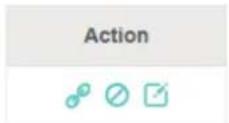

Reconnect the client to the network.

Restrict the client's access to the network.

Configure the rate limit of the client and view the connection history.
Enter the download limit and upload limit and click Apply.


If the client is a Guest, you can click this icon to cancel the authorization for it.
2.5 View Clients Statistics During the Specified Period
The Clients Statistics page under the Insight tab displays the information of clients that have connected to the EAPs network during a specified period.

2.5.1 Select a Specified Period
Select a period from the drop-down menu. Then the page will display clients that have connected to the EAPs network during the period.

2.5.2 View the History Information of Clients
You can click the client's MAC address to get its connection history and configure the Rate Limit feature for this client. In addition, you can click the following tabs to view the information of different types of clients:
| All | User | Guest | Blocked | Rate Limited |
All: The page displays the history information of all the clients.
User: The page displays the history information of Users.
Users are the clients connected to the EAP wireless network without the Portal Authentication.
Guest: The page displays the history information of Guests.
Guests are the clients connected to the EAP wireless network with the Portal Authentication.
Blocked: The page displays the clients that have been blocked.
Rate Limited: The page displays the clients that have been limited upload or download rate.
All / Offline Only
All: The page displays the history information of all clients.
Offline Only: The page displays the history information of the off-line clients.
2.5.3 Manage Clients in the Action Column
You can execute the corresponding operation to the EAP in the Action column:

Block the client's access to the network.

Resume the client's access.

Configure the rate limit of the client and view the connection history.

Remove the limit to the client's upload or download rates.
2.6 Manage the Rogue APs List
A Rogue AP is an access point that has been installed on a secure network without explicit authorization from a system administrator. The Omada Controller can scan all channels to detect
all nearby EAPs. If rogue APs are detected, they will be shown on the Untrusted Rogue APs list. Besides, you can move the untrusted rogue APs to the Trusted Rogue APs list.
By default, the Rogue AP Detection feature is disabled. To allow your EAP to detect nearby APs, you need to enable this feature for this EAP. You can refer to Rogue AP Detection.
2.6.1 Manage the Untrusted Rogue APs List
The Untrusted Rogue APs page displays the detailed information of untrusted rogue APs.

You can execute the corresponding operation to the EAP in the Action column:
| Move the untrusted rogue AP to the Trusted Rogue APs list. | |
| Delete this record. | |
| Delete all records. |
2.6.2 Manage the Trusted Rogue APs List
The Trusted Rogue APs page displays the detailed information of trusted rogue APs.
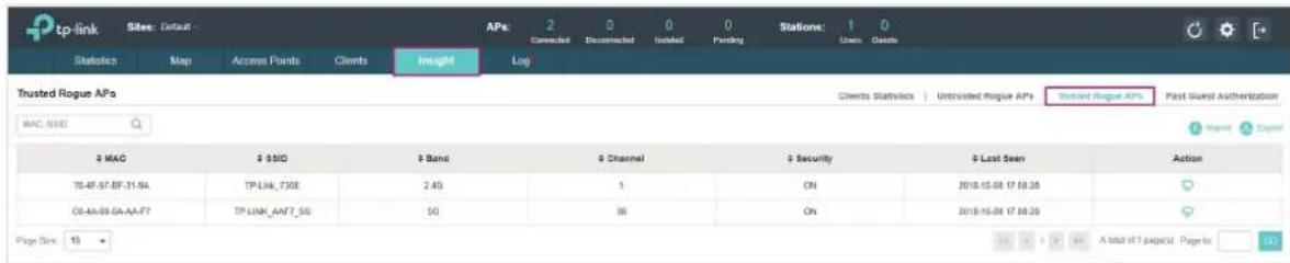
You can execute the corresponding operation to the EAP by clicking an icon in the Action column:

Move the trusted rogue AP to the Untrusted Rogue APs list.

Export and download the current Trusted Rogue APs list and save it on your PC.

Import
Import a saved Trusted Rogue APs list. If the MAC address of an AP appears in the list, it will not be detected as a rogue AP.

Please follow the steps below:
- Select Replace (replace the current Trusted Rogue APs list with the one you import) or Merge (add the APs in the file to the current Trusted Rogue APs list).
- Click Browse to locate the file and choose it.
- Click Import to import the Trusted Rogue APs list.
2.7 View Past Guest Authorization
The Past Guest Authorization page displays the details about all the clients that accessed the network during a certain time period. You can select a period in the drop-down list.

2.8 View Logs
The logs of Omada Controller can effectively record, classify and manage the system information of the managed EAPs, providing powerful support for you to monitor network operation and diagnose malfunctions. The Log page displays the log's module, level, content, operator and occurred time.

You can view the alerts on a separate page by clicking Alerts in the top right corner of the page. As follows, you can click 🔒 to mark the alerts as read.

Note:
The logs and alerts of the controller with version 3.0.5 or below will be discarded after the controller is upgraded to version 3.1.4 or above.
3 Configure the EAPs Globally
This chapter introduces the global configurations applied to all the managed EAPs. To configure a specific EAP, please refer to Chapter 5 Configure the EAPs Separately.
In global configurations, you can configure the following items:
■ Wireless Network ■ Access Control ■ Portal Authentication ■ Free Authentication Policy ■ MAC Filter ■ Scheduler ■ QoS ■ Site Settings
3.1 Wireless Network
In addition to the wireless network you created in Quick Start, you can add more wireless networks and configure the advanced wireless parameters to improve the network quality.
3.1.1 Add Wireless Networks
To add wireless networks, follow the steps below.
- Go to Wireless Settings > Basic Wireless Setting.

- Click at the right of to add a WLAN group. Creating WLAN groups
is an easy way to quickly deploy EAPs by creating a template-based set of SSIDs with wireless parameters. Different WLAN groups can be applied to different EAPs. If you have no need to group your wireless networks, you can use the default WLAN group and skip this step.
- Select the WLAN group and click to add an SSID to the specific WLAN group.

- Select the WLAN group and click to add an SSID to the specific WLAN group.

- Configure the parameters in the following window.
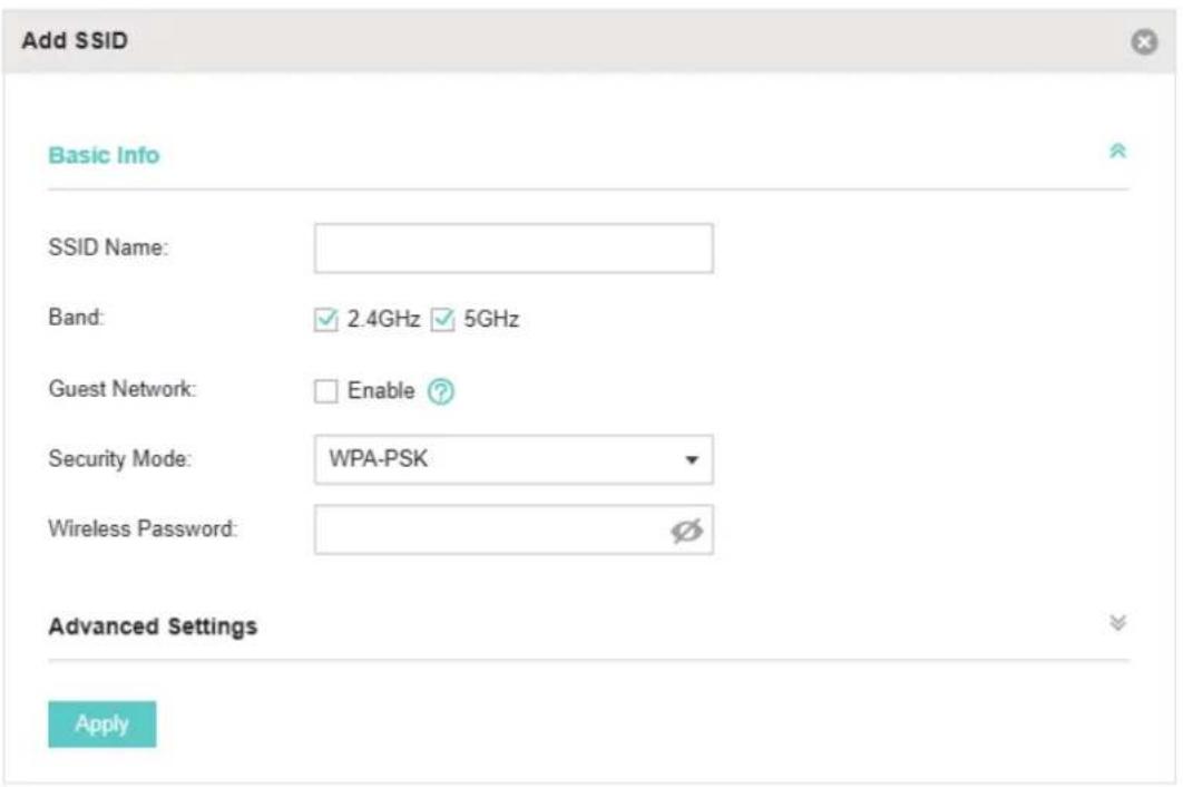
SSID Name: Enter an SSID name using up to 32 characters.
Band Select the radio band to add the SSID.
Guest Network With this option enabled, the network acts as a guest network. All clients connecting to the SSID will be blocked from reaching any private IP subnet.
Security Mode Select the security mode of the wireless network.
None: The hosts can access the wireless network without authentication.
WEP/WPA-Enterprise/WPA-PSK: The hosts need to get authenticated before accessing the wireless network. For network security, you are suggested to encrypt your wireless network.
Settings vary in different security modes and the details are in the following introduction.
Note:
- 8 SSIDs can be created on each band at most.
- The SSID on different radio bands with the same name will be regarded as an identical SSID entry. When you upgrade your controller or restore the backup files from the controller with version 3.0.5 or below, the SSID entries with the same name will be merged if they are on 2.4GHz and 5GHz in the same WLAN group. All the configurations in the entry will be changed to the parameters of the original SSID on the 2.4GHz radio band.
Following is the detailed introduction of None, WEP, WPA-Enterprise and WPA-PSK.
None
The hosts can access the wireless network without authentication. Configure the advanced parameters in the following window.
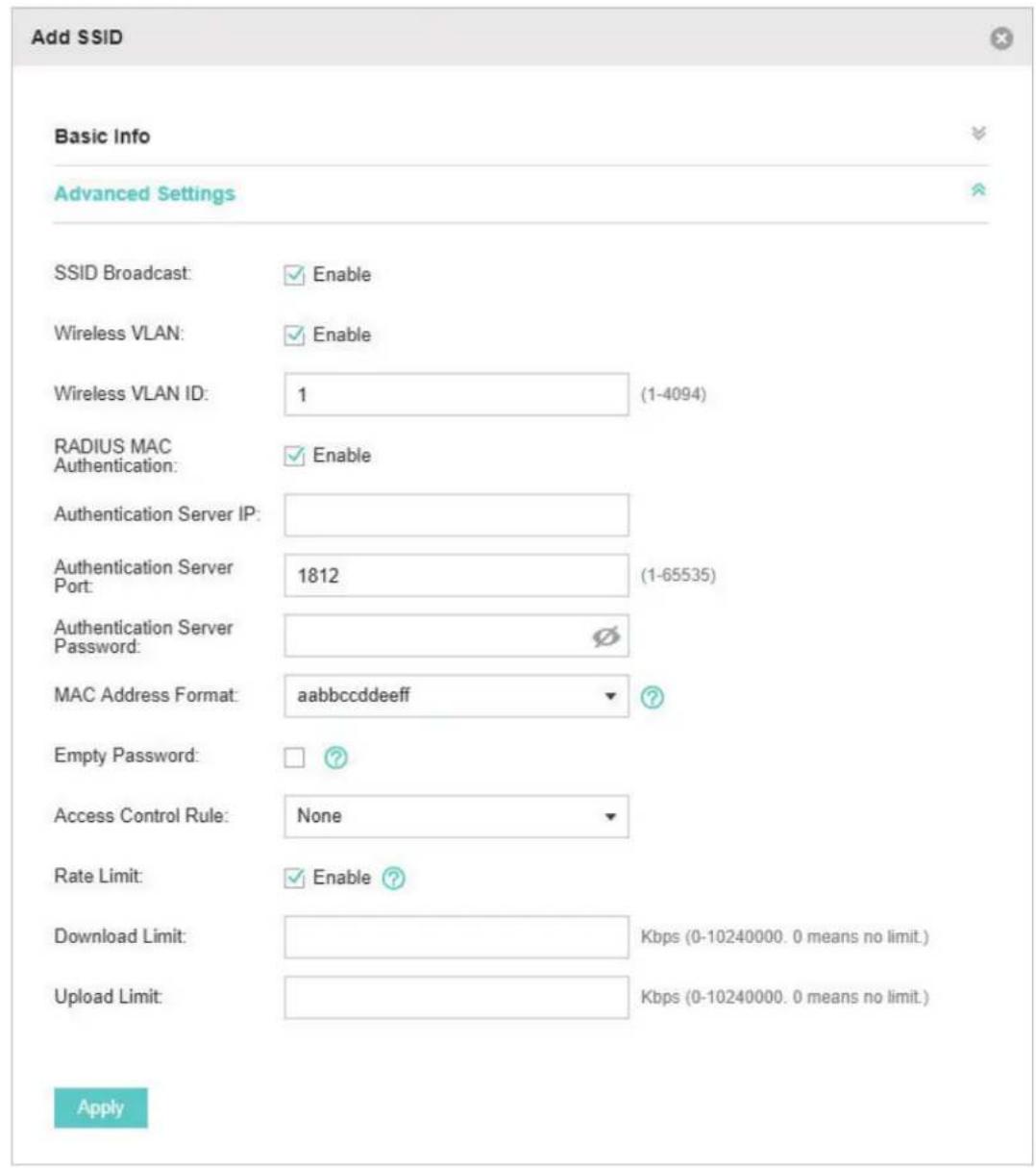
SSID Broadcast
With the option enabled, EAPs will broadcast the SSID to the nearby hosts, so that those hosts can find the wireless network identified by this SSID. If this option is disabled, users must enter the SSID manually to connect to the EAP.
The option is enabled by default.
| Wireless VLAN With this option enabled, the EAP can work together with the switches supporting 802.1Q VLAN. Traffic from the clients in different wireless networks is added with different VLAN tags according to the VLAN settings of the wireless networks. Then the wireless clients in different VLANs cannot directly communicate with each other.To set a wireless VLAN for the wireless network, enable the option and set a VLAN ID in the Wireless VLAN ID. | |
| Wireless VLAN ID | Enter a VLAN ID for the wireless VLAN. Wireless networks with the same VLAN ID are grouped to a VLAN. The value ranges from 1 to 4094. |
| RADIUS MAC Authentication | With this option enabled, the EAP will send the MAC address of the client to the RADIUS server as the username and password for authentication. If the authorization succeeds, the RADIUS server grants the client access to the network.To set RADIUS MAC Authentication, enable the option and configure the following parameters: Authentication Server IP, Authentication Server Port, Authentication Server Password, MAC Address Format, and Empty Password. |
| Authentication Server IP | With RADIUS MAC Authentication enabled, enter the IP address of the authentication server. |
| Authentication Server Port | With RADIUS MAC Authentication enabled, enter the port number you have set on the RADIUS server for authentication requests. The default setting is 1812. |
| Authentication Server Password | With RADIUS MAC Authentication enabled, enter the authentication password. The authentication server and the controller use the password to encrypt passwords and exchange responses. |
| MAC Address Format | With RADIUS MAC Authentication enabled, select the format to convert a client's MAC address to the RADIUS username. |
| Empty Password With the option enabled, a blank password for RADIUS MAC Authentication will be allowed. With the option disabled, the password will be the same as the username. | |
| Access Control Rule | Select an Access Control rule for this SSID. For more information, refer to Access Control. |
| Rate Limit | With this option enabled, the download and upload rate of each client which connects to the SSID will be limited to balance bandwidth usage. You can limit the download and upload rate for some specific clients by configuring rate limit in client list, refer to Manage Clients in the Action Column to get more details.Note that the download and upload rate will be limited to the minimum of the value configured in SSID, client and portal configuration. |
| Download Limit With Rate Limit enabled, specify the limit of download rate. 0 means unlimited. | |
| Upload Limit With Rate Limit enabled, specify the limit of upload rate. 0 means unlimited. | |
WEP
WEP is based on the IEEE 802.11 standard and is less secure than WPA-Enterprise and WPA-PSK.
Note:
WEP is not supported in 802.11n mode or 802.11ac mode. If WEP is applied in 802.11n, 802.11ac, or 802.11n/ac mixed mode, clients may not be able to access the wireless network. If WEP is applied in 11b/g/n mode (2.4GHz) or 11a/n (5GHz), the EAP may work at a low transmission rate.

Key Selected: Select one key to specify. You can configure up to four keys.
Key Value: Enter the WEP keys. The length and valid characters are affected by the key type.
Configure the advanced parameters in the following window.

| Type Select the authentication type for WEP. | |
| Auto: The Omada Controller can select Open System or Shared Key automatically based on the wireless station's capability and request. | |
| Open System: Clients can pass the authentication and associate with the wireless network without password. However, correct password is necessary for data transmission. | |
| Shared Key: Clients have to input password to pass the authentication, otherwise it cannot associate with the wireless network or transmit data. | |
| WEP Key Format | Select ASCII or Hexadecima as the WEP key format. |
| ASCII: ASCII format stands for any combination of keyboard characters of the specified length. | |
| Hexadecimal: Hexadecimal format stands for any combination of hexadecimal digits (0-9, a-f, A-F) with the specified length. | |
| Key Type Select the WEP key length for encryption. | |
| 64Bit: Enter 10 hexadecimal digits or 5 ASCII characters. | |
| 128Bit: Enter 26 hexadecimal digits or 13 ASCII characters. | |
| 152Bit: Enter 32 hexadecimal digits or 16 ASCII characters. | |
| Key Value Enter the WEP keys. The length and valid characters are affected by key type. | |
| SSID Broadcast | With the option enabled, EAPs will broadcast the SSID to the nearby hosts, so that those hosts can find the wireless network identified by this SSID. If this option is disabled, users must enter the SSID manually to connect to the EAP. |
| The option is enabled by default. | |
| Wireless VLAN With this option enabled, the EAP can work together with the switches supporting 802.1Q VLAN. Traffic from the clients in different wireless networks is added with different VLAN tags according to the VLAN settings of the wireless networks. Then the wireless clients in different VLANs cannot directly communicate with each other. | |
| To set a wireless VLAN for the wireless network, enable the option and set a VLAN ID in the Wireless VLAN ID. | |
| Wireless VLAN ID | Enter a VLAN ID for the wireless VLAN. Wireless networks with the same VLAN ID are grouped to a VLAN. The value ranges from 1 to 4094. |
| Access Control Rule | Select an Access Control rule for this SSID. For more information, refer to Access Control. |
| Rate Limit | With this option enabled, the download and upload rate of each client which connects to the SSID will be limited to balance bandwidth usage. You can limit the download and upload rate for some specific clients by configuring rate limit in client list, refer to Manage Clients in the Action Column to get more details. |
| Note that the download and upload rate will be limited to the minimum of the value configured in SSID, client and portal configuration. | |
| Download Limit With Rate Limit enabled, specify the limit of download rate. 0 means unlimited. | |
WPA-Enterprise
The WPA-Enterprise mode requires a RADIUS server to authenticate clients. Since WPA-Enterprise can generate different passwords for different clients, it is much more secure than WPA-PSK. However, it costs much more to maintain and is usually used by enterprises.

RADIUS Server IP: Enter the IP address of the RADIUS Server.
RADIUS Port: Enter the port number of the RADIUS Server.
RADIUS Password: Enter the shared secret key of the RADIUS server.
RADIUS Accounting: Enable or disable the RADIUS Accounting feature.
| Accounting Server IP | Enter the IP address of the accounting server. |
| Accounting Server Port | Enter the port number of the accounting server. |
| Accounting Server Password | Enter the shared secret key of the accounting server. |
| Interim Update | With this option enabled, you can specify the duration between accounting information updates. By default, the function is disabled.Enter the appropriate duration between updates for EAPs in Interim Update Interval. |
| Interim Update Interval | With Interim Update enabled, specify the appropriate duration between updates for EAPs. The default duration is 600 seconds. |
Configure the advanced parameters in the following window.

Version: Select the version of WPA-Enterprise.
Auto: The EAP will automatically choose the version used by each client device.
WPA/WPA2: Two versions of Wi-Fi Protected Access.
Encryption: Select the Encryption type.
Auto: The default setting is Auto and the EAP will select TKIP or AES automatically based on the client device's request.
TKIP: Temporal Key Integrity Protocol. TKIP is not supported in 802.11n mode, 802.11ac mode, or 802.11n/ac mixed mode. If TKIP is applied in 802.11n, 802.11ac, or 802.11n/ac mixed mode, the clients may not be able to access the wireless network of the EAP. If TKIP is applied in 11b/g/n mode (2.4GHz) or 11a/n mode (5GHz), the device may work at a low transmission rate.
AES: Advanced Encryption Standard. We recommend that you select AES as the encryption type because it is more secure than TKIP.
Group Key Update Period: Specify a group key update period, which instructs the EAP how often it should change the encryption keys. The value can be either 0 or 30~8640000 seconds. 0 means no change of the encryption key anytime.
| SSID Broadcast | With the option enabled, EAPs will broadcast the SSID to the nearby hosts, so that those hosts can find the wireless network identified by this SSID. If this option is disabled, users must enter the SSID manually to connect to the EAP.The option is enabled by default. |
| Wireless VLAN | With this option enabled, the EAP can work together with the switches supporting 802.1Q VLAN. Traffic from the clients in different wireless networks is added with different VLAN tags according to the VLAN settings of the wireless networks. Then the wireless clients in different VLANs cannot directly communicate with each other.To set a wireless VLAN for the wireless network, enable the option and set a VLAN ID in the Wireless VLAN ID. |
| Wireless VLAN ID Enter a VLAN ID for the wireless VLAN. Wireless networks with the same VLAN ID are grouped to a VLAN. The value ranges from 1 to 4094. | |
| Access Control Rule | Select an Access Control rule for this SSID. For more information, refer to Access Control. |
| Rate Limit | With this option enabled, the download and upload rate of each client which connects to the SSID will be limited to balance bandwidth usage. You can limit the download and upload rate for some specific clients by configuring rate limit in client list, refer to Manage Clients in the Action Column to get more details.Note that the download and upload rate will be limited to the minimum of the value configured in SSID, client and portal configuration. |
| Download Limit With Rate Limit enabled, specify the limit of download rate. 0 means unlimited. | |
| Upload Limit With Rate Limit enabled, specify the limit of upload rate. 0 means unlimited. | |
WPA-PSK
Based on a pre-shared key, WPA-PSK is characterized by high safety and simple settings and is mostly used by common households and small businesses.

| Wireless Password | Configure the wireless password with ASCII or Hexadecimal characters. For ASCII, the length should be between 8 and 63 characters with combination of numbers, letters (case-sensitive) and common punctuations. For Hexadecimal, the length should be 64 characters (case-insensitive, 0-9, a-f, A-F). |
Configure the advanced parameters in the following window.

Version: Select the version of WPA-Enterprise.
Auto: The EAP will automatically choose the version used by each client device.
WPA/WPA2: Two versions of Wi-Fi Protected Access.
Encryption: Select the Encryption type.
Auto: The default setting is Auto and the EAP will select TKIP or AES automatically based on the client request.
TKIP: Temporal Key Integrity Protocol. TKIP is not supported in 802.11n mode, 802.11ac mode or 802.11n/ac mixed mode. If TKIP is applied in 802.11n, 802.11ac or 802.11n/ac mixed mode, the clients may not be able to access the wireless network of the EAP. If TKIP is applied in 11b/g/n mode (2.4GHz) or 11a/n mode (5GHz), the device may work at a low transmission rate.
AES: Advanced Encryption Standard. We recommend that you select AES as the encryption type for it is more secure than TKIP.
Group Key Update Period: Specify a group key update period, which instructs the EAP how often it should change the encryption keys. The value can be either 0 or 30~8640000 seconds. 0 means the encryption keys will not be changed at all.
| SSID Broadcast | With the option enabled, EAPs will broadcast the SSID to the nearby hosts, so that those hosts can find the wireless network identified by this SSID. If this option is disabled, users must enter the SSID manually to connect to the EAP.The option is enabled by default. |
| Wireless VLAN | With this option enabled, the EAP can work together with the switches supporting 802.1Q VLAN. Traffic from the clients in different wireless networks is added with different VLAN tags according to the VLAN settings of the wireless networks. Then the wireless clients in different VLANs cannot directly communicate with each other.To set a wireless VLAN for the wireless network, enable the option and set a VLAN ID in the Wireless VLAN ID. |
| Wireless VLAN ID Enter a VLAN ID for the wireless VLAN. Wireless networks with the same VLAN ID are grouped to a VLAN. The value ranges from 1 to 4094. | |
| Access Control Rule | Select an Access Control rule for this SSID. For more information, refer to Access Control. |
| Rate Limit | With this option enabled, the download and upload rate of each client which connects to the SSID will be limited to balance bandwidth usage. You can limit the download and upload rate for some specific clients by configuring rate limit in client list, refer to Manage Clients in the Action Column to get more details.Note that the download and upload rate will be limited to the minimum of the value configured in SSID, client and portal configuration. |
| Download Limit With Rate Limit enabled, specify the limit of download rate. 0 means unlimited. | |
| Upload Limit With Rate Limit enabled, specify the limit of upload rate. 0 means unlimited. | |
6. Click Apply.
3.1.2 Configure Advanced Wireless Parameters
Proper wireless parameters can improve the network's stability, reliability and communication efficiency. The advanced wireless parameters consist of Fast Roaming, Beacon Interval, DTIM Period, RTS Threshold, Fragmentation Threshold and Airtime Fairness.
To configure the advanced wireless parameters, follow the steps below.
- Go to Wireless Settings > Advanced Wireless Setting.

- Enable Fast Roaming and configure the corresponding parameters.

| Fast Roaming With this option enabled, 11k/v capable clients can have improved fast roaming experience when moving among different APs. | |
| Dual Band 11k Report | With this feature disabled, the controller provides candidate AP report that contains the APs in the same band as the clients. With this feature enabled, the controller provides candidate AP report that contains the APs in both 2.4GHz and 5GHz bands. |
| Force-disassociation | The controller dynamically monitors the link quality of every associated client. When the client's current link quality drops below the predefined threshold and there are some other APs with better signal, the current AP issues an 11v roaming suggestion to the client.With Force-disassociation disabled, the AP only issues a roaming suggestion, but whether to roam or not is determined by the client.With Force-disassociation enabled, the AP not only issues a roaming suggestion but also disassociates the client after a while. Thus the client is supported to re-associate to a better AP. This function is recommended when there are sticky clients that don't roam. |
- Click Apply.
4. Select the band frequency
2.4GHz
5GHz
5. Configure the following parameters.
| Beacon Interval | Beacons are transmitted periodically by the EAP to announce the presence of a wireless network for the clients. Beacon Interval value determines the time interval of the beacons sent by the device.You can specify a value between 40 and 100ms. The default is 100ms. |
| DTIM Period | The DTIM (Delivery Traffic Indication Message) is contained in some Beacon frames. It indicates whether the EAP has buffered data for client devices. The DTIM Period indicates how often the clients served by this EAP should check for buffered data still on the EAP awaiting pickup.You can specify the value between 1-255 Beacon Intervals. The default value is 1, indicating clients check for buffered data on the EAP at every beacon. An excessive DTIM interval may reduce the performance of multicast applications, so we recommend that you keep it by default. |
| RTS Threshold | RTS (Request to Send) can ensure efficient data transmission. When RTS is activated, the client will send a RTS packet to EAP to inform that it will send data before it send packets. After receiving the RTS packet, the EAP notices other clients in the same wireless network to delay their transmitting of data and informs the requesting client to send data, thus avoiding the conflict of packet.If the size of packet is larger than the RTS Threshold, the RTS mechanism will be activated.If you specify a low threshold value, RTS packets are sent more frequently and help the network recover from interference or collisions that might occur on a busy network. However, it also consumes more bandwidth and reduces the throughput of the packet. We recommend that you keep it by default. The recommended and default value is 2347. |
| Fragmentation Threshold | The fragmentation function can limit the size of packets transmitted over the network. If a packet exceeds the Fragmentation Threshold, the fragmentation function is activated and the packet will be fragmented into several packets.Fragmentation helps improve network performance if properly configured. However, too low fragmentation threshold may result in poor wireless performance caused by the extra work of dividing up and reassembling of frames and increased message traffic. The recommended and default value is 2346 bytes. |
| Airtime Fairness | With this option enabled, each client connecting to the EAP can get the same amount of time to transmit data, avoiding low-data-rate clients to occupy too much network bandwidth and improving the network throughput. We recommend that you enable this function under multi-rate wireless networks. |
6. Click Apply.
3.1.3 Configure Band Steering
A client device that is capable of communicating on both the 2.4GHz and 5GHz frequency bands will typically connect to the 2.4GHz band. However, if too many client devices are connected to an EAP on the 2.4GHz band, the efficiency of communication will be diminished. Band Steering can steer
dual-band clients to the 5GHz frequency band which supports higher transmission rates and more client devices, and thus greatly improve the network quality.
To configure Band Steering, follow the steps below.
1. Go to Wireless Settings > Band Steering.
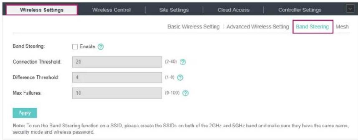
- Check the box to enable the Band Steering function.
- Configure the following parameters to balance the clients on both frequency bands:
| Connection Threshold/ Difference Threshold | Connection Threshold defines the maximum number of clients connected to the 5GHz band. The value of Connection Threshold is from 2 to 40, and the default is 20. |
| Difference Threshold defines the maximum difference between the number of clients on the 5GHz band and 2.4GHz band. The value of Difference Threshold is from 1 to 8, and the default is 4. | |
| When the following two conditions are both met, the EAP prefers to refuse the connection request on 5GHz band and no longer steers other clients to the 5GHz band: | |
| 1. The number of clients on the 5GHz band reaches the Connection Threshold value. | |
| 2. The difference between the number of clients on the 2.4GHz band and 5GHz band reaches the Difference Threshold value. |
| Max Failures If a client repeatedly attempts to associate with the EAP on the 5GHz band and the number of rejections reaches the value of Max Failures, the EAP will accept the request.The value is from 0 to 100, and the default is 10. |
- Click Apply.
3.1.4 Configure Mesh
Mesh is used to establish a wireless network or expand a wired network through wireless connection on the 5GHz radio band. In practical application, it can help users to conveniently deploy APs without requiring Ethernet cable. After the mesh network is established, the EAPs can be configured
and managed within Omada controller in the same way as wired EAPs. Meanwhile, because of the ability to self-organize and self-configure, mesh also can efficiently reduce the configuration overhead.
Note:
- EAP225-Outdoor with specific firmware (version 1.3 or above) and EAP225 V3 with specific firmware (version 2.5.0 or above) are available for mesh function currently.
- Only the EAPs in the same site can establish a mesh network.
To understand how mesh can be used, the following terms used in Omada Controller will be introduced:
■Root AP: The AP is managed by Omada Controller with a wired data connection that can be configured to relay data to and from mesh APs (Downlink AP). ■Isolated AP: When the EAP which has been managed before by Omada Controller connects to the network wirelessly and cannot reach the gateway, it goes into the Isolated state. ■Mesh AP: An isolated AP will be mesh AP after establishing a wireless connection to the AP with network access. ■Uplink AP/Downlink AP: Among mesh APs, the AP that offers the wireless connection for other APs is Uplink AP. A Root AP or an intermediate AP can be the Uplink AP. And the AP that connects to the Uplink AP is called Downlink AP. An uplink AP can offer direct wireless connection for 4 Downlink APs at most. ■Wireless Uplink: The action that a Downlink AP connects to the uplink AP. ■Hops: In a deployment that uses a root AP and more than one level of wireless uplink with intermediate APs, the uplink tiers can be referred to by root, first hop, second hop and so on. The hops cannot be more than 3.
In a basic mesh network as shown below, there is a root AP that is connected by Ethernet cable, while other isolated APs have no wired data connection. Mesh allows the isolated APs to communicate with pre-configured root AP on the network. Once powered up, factory default or unadopted EAPs can sense the EAP in range and make itself available for adoption within the Omada controller.
![graph LR A["Host A (Controller Host) Switch"] --> B["Router (DHCP Server)"] B --> C["Internet"] C --> D["Wireless Uplink"] D --> E["Root AP Mesh AP (Hops: 1)"] E --> F["Mesh APs (Hops: 2)"] G["Omega Controller"] --> A](/content/2026/06/1336671/images/9a775829e34251060667fa6f6d8fe4943b03a4e15b8ad318819d7c81da6f3135.jpg)
After all the EAPs are adopted, a mesh network is established. Then the EAPs connected to the network wirelessly also can broadcast SSIDs and relay network traffic to and from the network through the uplink AP.
To establish a mesh network, follow the steps below.
■Enable Mesh Function. ■Adopt the Root AP. ■Set up wireless uplink by adopting APs in Pending (Wireless) or Isolated status.
- Go to Wireless Settings > Mesh.
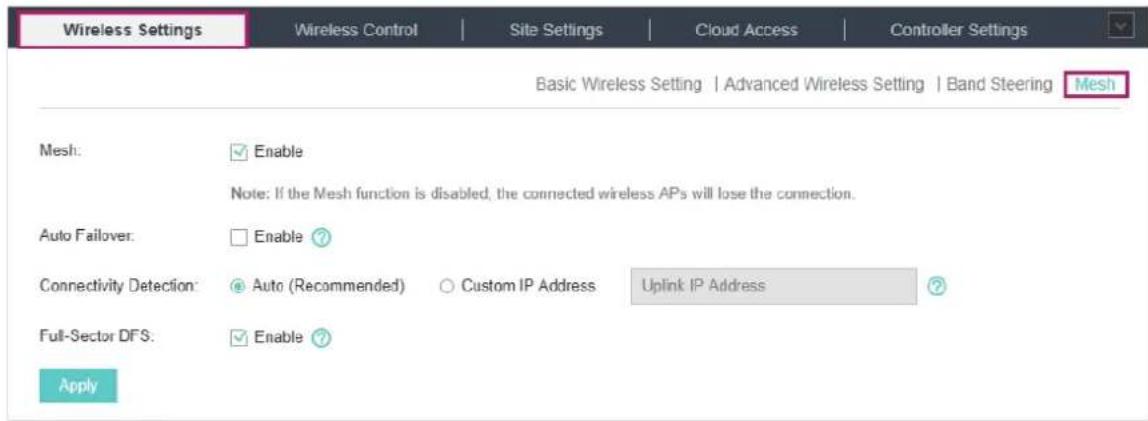
- Check the box to enable the Mesh function.
- Configure the following parameters to maintain the mesh network:
Auto Failover Enable or disable Auto Failover.
Auto Failover is used to automatically maintain the mesh network for the controller. With this feature enabled, the controller can automatically select an uplink AP for the isolated EAP to establish Wireless Uplink. Thus the controller will automatically select a new uplink AP for the mesh EAPs when the original uplink fails.
Connectivity Detection Specify the method of Connection Detection.
In a mesh network, the APs can send ARP request packets to a fixed IP address to test the connectivity. If the link fails, the status of these APs will change to Isolated.
Auto (Recommended): Select this method and the mesh APs will send ARP request packets to the default gateway for the detection.
Custom IP Address: Select this method and specify a desired IP address. The mesh APs will send ARP request packets to the custom IP address to test the connectivity. If the IP address of the AP is in different network segments from the custom IP address, the AP will use the default gateway IP address for the detection.
Full-Sector DFS: With this feature enabled, when radar signals are detected on the current channel by one EAP, the other EAPs in the mesh network will also be informed. Then all EAPs in the mesh network will switch to an alternate channel.
- Click Apply.
- Go to Access Points > Pending and adopt the Root AP. Then the status of the Root AP will change into Connected.

- Install the EAP that will uplink the Root AP wirelessly. Make sure the intended location is within the range of the Root AP. The EAPs that are waiting for Wireless Uplink include two cases: factory default EAPs and EAPs that have been managed by Omada Controller before.
1) For the factory default EAP, after powering on the device, the EAP will be in Pending (Wireless) status shown in the controller. Go to Access Points > Pending and adopt the EAPs in Pending (Wireless) status.

After adoption begins, the status of Pending (Wireless) EAP will become Adopting (Wireless) and then Connected (Wireless). It should take roughly 2 minutes to show up Connected (Wireless) within your controller.
2) For the EAP that has been managed by Omada Controller before and cannot reach the gateway, it goes into Isolated status when it is discovered by the controller again. Go to Access
Points > Isolated, click 📄.

The following page will be shown, go to Mesh, then click to connect the Uplink AP.
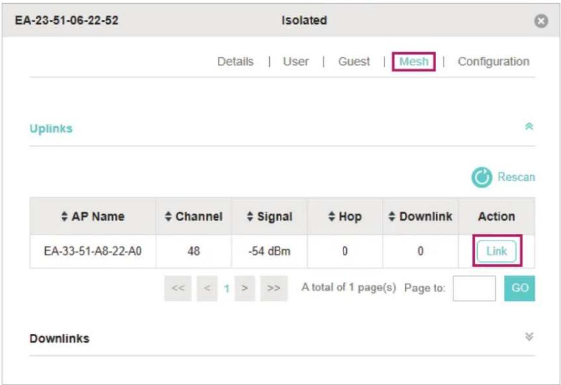
Once adoption has finished, your device can be managed by the controller in the same way as a wired EAP. You can click the EAP's name on the Access Points tab to view and configure the mesh parameters of the EAP on the pop-up window. Please refer to View Mesh Information of the EAP.
Tips:
- You can manually select the uplink AP that you want to connect in the uplink EAP list. To build a mesh network with better performance, we recommend that you select the Uplink AP with the strongest signal, least hop, and least Downlink AP.
- You can enable Auto Failover to make the controller automatically select an uplink AP for the isolated EAP to establish Wireless Uplink. And the controller will automatically select a new uplink AP for the mesh EAPs when the original uplink fails.
3.2 Access Control
Access Control is used to block or allow clients to access specific subnets. To configure Access Control rules, follow the steps below.
1. Go to Wireless Control > Access Control.
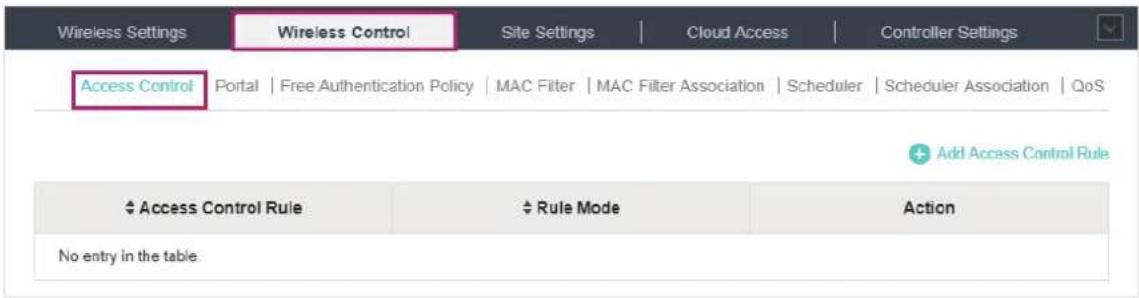
2. Click to add a new Access Control rule.

3. Configure the following parameters.
Rule Name: Specify a name for this rule.
Rule Mode: Select the mode for this rule.
Block: Select this mode to block clients from accessing the specific subnets.
Allow: Select this mode to allow clients to access the specific subnets.
Rule Members: Specify the member subnets for this rule.
Subnets: Enter the subnet that will follow the rule mode in the format X.X.X.X/X and click Add New. Up to 16 subnets can be added.
Except Subnets: Enter the excepted subnet in the format X.X.X.X/X and click Add New. Up to 16 subnets can be added. The rule mode will not apply to the subnet that is in both the Subnets list and the Except Subnets list.
4. Click Apply.
- Go to Wireless Settings > Basic Wireless Setting and enable the Access Control function of a selected SSID.
3.3 Portal Authentication
Portal authentication enhances network security by providing authentication services to clients who only need temporary access to the wireless network. Such clients must log into a web page to complete verification, after which they can access the network as guests. Additionally, you can customize the authentication login page and specify a URL to which newly authenticated clients will be redirected.
To configure Portal Authentication, go to Wireless Control > Portal and click + Add a New Portal.

The following window will then appear:

The available authentication methods are: No Authentication, Simple Password, Local User, Voucher, SMS, Facebook, External RADIUS Server, and External Portal Server. The following sections explain how to configure each Portal authentication method.
3.3.1 No Authentication
With No Authentication configured, clients can access the network without any authentication.
Follow the steps below to configure No Authentication:
- Go to Wireless Settings > Basic Wireless Settings and create an SSID for the Portal.
- Return to the Portal configuration page. In the Basic Info section, complete the basic settings for the portal authentication.
Basic Info
Portal Name:
SSID:
Authentication Type:
Authentication Timeout:
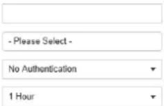
Daily Limit ?
HTTPS Redirect:
Redirect:
Enable ?
Enable ?
Redirect URL:

Configure the following parameters:
Portal Name: Specify a name for the Portal.
SSID: Select an SSID for the Portal.
Authentication Type: Select No Authentication.
Authentication Timeout
With Daily Limit disabled, the client's authentication will expire after the time period you set and the client needs to log in again on the web authentication page to access the network.
Options include 1 Hour, 8 Hours, 24 Hours, 7 Days and Custom. Custom allows you to define the time in days, hours and minutes. The default value is one hour.
With Daily Limit enabled, the client's authentication will expire after the time period you set and the client cannot log in again in the same day.
Options include 30 Minutes, 1 Hour, 2 Hours, 4 Hours and Custom. Custom allows you to define the time in hours and minutes. The default value is 30 minutes.
Daily Limit: With Daily Limit enabled, after authentication times out, the user cannot get authenticated again in the same day.
HTTPS Redirect: With this function enabled, unauthorized clients will be redirected to the Portal page when they try to browse HTTPS websites.
With this function disabled, unauthorized clients cannot browse HTTPS websites and are not redirected to the Portal page.
Redirect: If you enable this function, the portal will redirect newly authenticated clients to the configured URL.
Redirect URL
If the Redirect function above is enabled, enter the URL that a newly authenticated client will be redirected to.
3. In the Login Page section, configure the login page for the Portal.
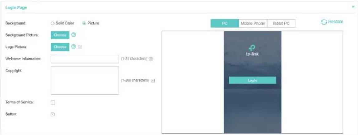
Configure the following parameters:
| Background | Select the background type. Two types are supported: Solid Color and Picture. |
| Background Color | If Solid Color is selected, configure your desired background color through the color picker or by entering the RGB value manually. |
| Background Picture | If Picture is selected, click the Choose button and select a picture from your PC. Drag and scale the clipping region to edit the picture and click Confirm. |
| Logo Picture | Click the Choose button and select a picture from your PC. Drag and scale the clipping region to edit the picture and click Confirm.In addition, you can click and configure the logo position. The options include Middle, Upper and Lower. |
Welcome Information: Specify the welcome information.
In addition, you can click 📋 and select your desired text color for the welcome information through the color picker or by entering the RGB value manually.

Copyright: Specify the copyright information.
In addition, you can click 📋 and select your desired text color for Copyright information through the color picker or by entering the RGB value manually.

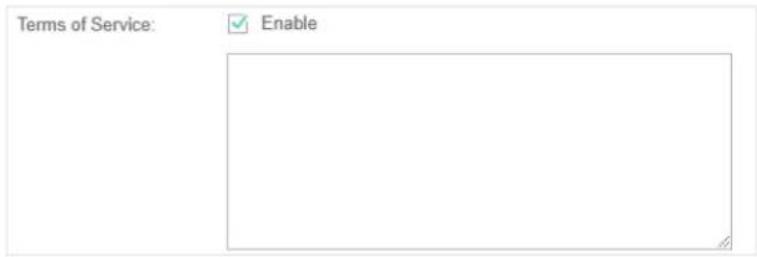
Terms of Service
Enable or disable Terms of Service. With this option enabled, specify the terms of service in the following box.
Button
Click 📋 and configure the button.
Button Position: Set the position of the login button. The options include Middle, Upper and Lower.
Button Color: Select your desired login button color through the color picker or by entering the RGB value manually.
Button Text Color: Select your desired text color for the button through the color picker or by entering the RGB value manually.

- In the Advertisement section, select whether to display advertisement pictures for users and configure the related parameters.
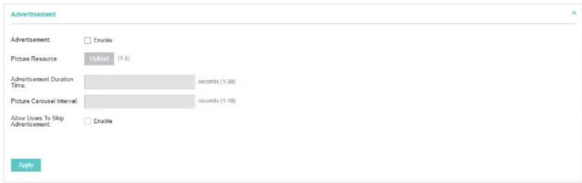
Configure the following parameters:
Advertisement
Specify whether to enable the Advertisement feature. With this feature enabled, you can add advertisement pictures on the authentication page. These advertisement pictures will be displayed before the login page appears. You can also allow users to skip the advertisement by enabling Allow Users To Skip Advertisement. The advertisement picture should be less than 2MB. And only JPG, PNG, BMP, GIF and JPEG file types are supported.
| Picture Resource | Upload advertisement pictures. When several pictures are added, they will be played in a loop. |
| Advertisement Duration Time | Specify how long the advertisement will be displayed for. For this duration, the pictures will be played in a loop. If the duration time is not enough for all the pictures, the rest will not be displayed. |
| Picture Carousel Interval | Specify the picture carousel interval. For example, if this value is set as 5 seconds, the first picture will be displayed for 5 seconds, followed by the second picture for 5 seconds, and so on. |
| Allow Users To Skip Advertisement | Specify whether to enable this feature. With this feature enabled, the user can click the Skip button to skip the advertisement. |
5. Click Apply.
3.3.2 Simple Password
With this Simple Password configured, clients are required to enter the correct password to pass the authentication.
Follow the steps below to configure No Simple Password Portal:
- Go to Wireless Settings > Basic Wireless Settings and create an SSID for the Portal.
- Go back to the Portal configuration page. In the Basic Info section, complete the basic settings for the portal authentication.

Configure the following parameters:
Portal Name Specify a name for the Portal.
SSID: Select an SSID for the Portal.
Authentication Type: Select Simple Password.
Password: Set the password for authentication.
| AuthenticationTimeout | The client's authentication will expire after the time period you set and the client needs to log in again on the web authentication page to access the network.Options include 1 Hour, 8 Hours, 24 Hours, 7 Days and Custom. Custom allows you to define the time in days, hours and minutes. The default value is one hour. |
| HTTPS Redirect With this function enabled, the unauthorized clients will be redirected to the Portal page when they are trying to browse HTTPS websites.With this function disabled, the unauthorized clients cannot browse HTTPS websites and are not redirected to the Portal page. | |
| Redirect If you enable this function, the portal will redirect the newly authenticated clients to the configured URL. | |
| Redirect URL | If the Redirect function above is enabled, enter the URL that a newly authenticated client will be redirected to. |
3. In the Login Page section, configure the login page for the Portal.

Configure the following parameters:
| Background | Select the background type. Two types are supported: Solid Color and Picture. |
| Background Color | If Solid Color is selected, configure your desired background color through the color picker or by entering the RGB value manually. |
| Background Picture | If Picture is selected, click the Choose button and select a picture from your PC. Drag and scale the clipping region to edit the picture and click Confirm. |
Logo Picture
Click the Choose button and select a picture from your PC. Drag and scale the clipping region to edit the picture and click Confirm.
In addition, you can click 📋 and configure the logo position. The options include Middle, Upper, and Lower.

Welcome Information: Specify the welcome information.
In addition, you can click 📋 and select your desired text color for the welcome information through the color picker or by entering the RGB value manually.

Copyright: Specify the copyright information.
In addition, you can click 📋 and select your desired text color for Copyright information through the color picker or by entering the RGB value manually.

Terms of Service
Enable or disable Terms of Service. With this option enabled, specify the terms of service in the following box.

Input Box
Click 📋 and configure the input box.
Select your desired color for the input box through the color picker or by entering the RGB value manually.

Button
Click 📋 and configure the button.
Button Position: Set the position of the login button. The options include Middle, Upper and Lower.
Button Color: Select your desired login button color through the color picker or by entering the RGB value manually.
Button Text Color: Select your desired text color for the button through the color picker or by entering the RGB value manually.

- In the Advertisement section, select whether to display advertisement pictures for users and configure the related parameters.
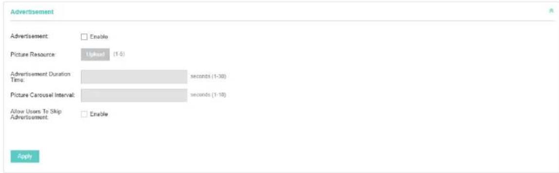
Configure the following parameters:
| Advertisement Specify whether to enable the Advertisement feature. With this feature enabled, you can add advertisement pictures on the authentication page. These advertisement pictures will be displayed before the login page appears. You can also allow users to skip the advertisement by enabling Allow Users To Skip Advertisement. The advertisement picture should be less than 2MB. And only JPG, PNG, BMP, GIF and JPEG file types are supported. | |
| Picture Resource | Upload advertisement pictures. When several pictures are added, they will be played in a loop. |
| Advertisement Duration Time | Specify how long the advertisement will be displayed for. For this duration, the pictures will be played in a loop. If the duration time is not enough for all the pictures, the rest will not be displayed. |
| Picture Carousel Interval | Specify the picture carousel interval. For example, if this value is set as 5 seconds, the first picture will be displayed for 5 seconds, followed by the second picture for 5 seconds, and so on. |
| Allow Users To Skip Advertisement | Specify whether to enable this feature. With this feature enabled, the user can click the Skip button to skip the advertisement. |
5. Click Apply.
3.3.3 Local User
With this Local User configured, clients are required to enter the correct username and password of the login account to pass the authentication. You can create multiple accounts and assign different accounts for different users.
Configure Local User Portal
Follow the steps below to configure Local User Portal:
- Go to Wireless Settings > Basic Wireless Settings and create an SSID for the Portal.
- Go back to the Portal configuration page. In the Basic Info section, complete the basic settings for the portal authentication.

Configure the following parameters:
| Portal Name Specify a name for the Portal. | |
| SSID Select an SSID for the Portal. | |
| Authentication Type Select Local User. | |
| User Management | You can click this button to configure user accounts for authentication later.Please refer to Create Local User Accounts. |
| HTTPS Redirect With this function enabled, the unauthorized clients will be redirected to the Portal page when they are trying to browse HTTPS websites.With this function disabled, the unauthorized clients cannot browse HTTPS websites and are not redirected to the Portal page. | |
| Redirect If you enable this function, the portal will redirect the newly authenticated clients to the configured URL. | |
| Redirect URL | If the Redirect function above is enabled, enter the URL that a newly authenticated client will be redirected to. |
- In the Login Page section, configure the login page for the Portal.

Configure the following parameters:
| Background | Select the background type. Two types are supported: Solid Color and Picture. |
| Background Color | If Solid Color is selected, configure your desired background color through the color picker or by entering the RGB value manually. |
| Background Picture | If Picture is selected, click the Choose button and select a picture from your PC. Drag and scale the clipping region to edit the picture and click Confirm. |
| Logo Picture | Click the Choose button and select a picture from your PC. Drag and scale the clipping region to edit the picture and click Confirm.In addition, you can click [IMAGE] and configure the logo position. The options include Middle, Upper and Lower. |
Welcome Information: Specify the welcome information.
In addition, you can click the color picker icon and select your desired text color for the welcome information through the color picker or by entering the RGB value manually.

Copyright: Specify the copyright information.
In addition, you can click the color picker icon and select your desired text color for the copyright information through the color picker or by entering the RGB value manually.

| Terms of Service | Enable or disable Terms of Service. With this option enabled, specify the terms of service in the following box. |
| Input Box | Click and configure the input box.Select your desired color for the input box through the color picker or by entering the RGB value manually.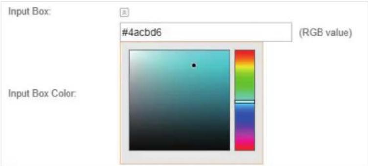 |
| Button | Click and configure the button.Button Position: Set the position of the login button. The options include Middle, Upper and Lower.Button Color: Select your desired login button color through the color picker or by entering the RGB value manually.Button Text Color: Select your desired text color for the button through the color picker or by entering the RGB value manually. |
- In the Advertisement section, select whether to display advertisement pictures for users and configure the related parameters.

Configure the following parameters:
| Advertisement | Specify whether to enable the Advertisement feature. With this feature enabled, you can add advertisement pictures on the authentication page. These advertisement pictures will be displayed before the login page appears. You can also allow users to skip the advertisement by enabling Allow Users To Skip Advertisement. The advertisement picture should be less than 2MB. And only JPG, PNG, BMP, GIF and JPEG file types are supported. |
| Picture Resource | Upload advertisement pictures. When several pictures are added, they will be played in a loop. |
| Advertisement Duration Time | Specify how long the advertisement will be displayed for. For this duration, the pictures will be played in a loop. If the duration time is not enough for all the pictures, the rest will not be displayed. |
| Picture Carousel Interval | Specify the picture carousel interval. For example, if this value is set as 5 seconds, the first picture will be displayed for 5 seconds, followed by the second picture for 5 seconds, and so on. |
| Allow Users To Skip Advertisement | Specify whether to enable this feature. With this feature enabled, the user can click the Skip button to skip the advertisement. |
5. Click Apply.
Create Local User Accounts
Follow the steps below to create the user accounts for authentication:
- In the Basic Info section on the portal configuration page, click User Management. The management page will appear. Go to the User page and click Create User.

- The following window will pop up. Configure the required parameters and click Apply.

Configure the following parameters:
| Username Specify the username. The username should not be the same as any existing one. | |
| Password Specify the password. Users will be required to enter the username and password when they attempt to access the network. | |
| AuthenticationTimeout | Specify the authentication timeout for formal users. After timeout, the users need to log in again on the web authentication page to access the network. |
| MAC Address BindingType | There are three types of MAC binding: No Binding, Static Binding and Dynamic Binding.Static Binding: Specify a MAC address for this user account. Then only the user with the this MAC address can use the username and password to pass the authentication.Dynamic Binding: The MAC address of the first user that passes the authentication will be bound. Then only this user can use the username and password to pass the authentication. |
Maximum Users: Specify the maximum number of users able to use this account to pass authentication.
Name: Specify a name for identification.
Telephone: Specify a telephone number for identification.
Rate Limit (Download): Select whether to enable download rate limit. With this option enabled, you can specify the limit of download rate.
Rate Limit (Upload): Select whether to enable upload rate limit. With this option enabled, you can specify the limit of upload rate.
Traffic Limit: Select whether to enable traffic limit. With this option enabled, you can specify the total traffic limit for the user. Once the limit is reached, the user can no longer use this account to access the network.
- In the same way, you can add more user accounts. The created user accounts will be displayed in the list. Users can use the username and password of the account to pass the portal authentication.
By default, the account Status is ☐, which means that the user account is enabled and valid. You can also click this button to disable the user account. The icon will be changed to ☐, which means that the user account is disabled.

Additionally, you can click to backup all the user account information into a CSV
file or XLS file and save the file to your PC. If needed, you can click Import Users and select the file to import the account information to the list.
Note:
Using Excel to open the CSV file may cause some numerical format changes, and the number may be displayed incorrectly. If you use Excel to edit the CSV file, please set the cell format as text.
Manage the Guests
On the Guest page, you can view the information of clients that have passed the portal authentication and manage the clients.

You can select an icon to execute the corresponding operation:

Disconnect client.

Extend the effective time.
Create Operator Accounts
Operator account can be used to remotely manage the Local User Portal and Voucher Portal. Other users can visit the URL https://Omada Controller Host's IP Address:8043/hotspot (For example: https://192.168.0.64:8043/hotspot) and use the Operator account to enter the portal management page.
Note:
- Make sure the host that is used to enter the portal management page with operator account can visit the Controller host.
- Only the user that log in to the controller with the administrator role can add or remove the operator account for portal management.
- The users who enter the portal management page by operator account can only create local user accounts and vouchers and manage the clients.
Follow the steps below to create Operator account.
1. Go to the Operator page.

2. Click and the following window will pop up.

- Specify the Name, Password and Notes of the Operator account.
- Select Site Privileges from the drop-down list (multiple options available) for the Operator account.
- Click Apply to create an Operator account. Then other users can use this account to enter the hotspot management page.
3.3.4 Voucher
With Voucher configured, you can distribute the vouchers automatically generated by the Omada Controller to the clients. Clients can use the vouchers to access the network.
Configure Voucher Portal
Follow the steps below to configure Voucher Portal:
- Go to Wireless Settings > Basic Wireless Settings and create an SSID for the Portal.
- Go back to the Portal configuration page. In the Basic Info section, complete the basic settings for the portal authentication.

Configure the following parameters:
Portal Name Specify a name for the Portal.
SSID Select an SSID for the Portal.
Authentication Type Select Voucher.
User Management You can click this button to configure vouchers for authentication later. Please refer to Create Vouchers.
HTTPS Redirect With this function enabled, the unauthorized clients will be redirected to the Portal page when they are trying to browse HTTPS websites.
With this function disabled, the unauthorized clients cannot browse HTTPS websites and are not redirected to the Portal page.
Redirect If you enable this function, the portal will redirect the newly authenticated clients to the configured URL.
Redirect URL: If the Redirect function above is enabled, enter the URL that a newly authenticated client will be redirected to.
- In the Login Page section, configure the login page for the Portal.

Configure the following parameters:
| Background | Select the background type. Two types are supported: Solid Color and Picture. |
| Background Color | If Solid Color is selected, configure your desired background color through the color picker or by entering the RGB value manually. |
| Background Picture | If Picture is selected, click the Choose button and select a picture from your PC. Drag and scale the clipping region to edit the picture and click Confirm. |
| Logo Picture | Click the Choose button and select a picture from your PC. Drag and scale the clipping region to edit the picture and click Confirm.In addition, you can click [IMAGE] and configure the logo position. The options include Middle, Upper and Lower. |
Welcome Information: Specify the welcome information.
In addition, you can click the clipboard icon and select your desired text color for the welcome information through the color picker or by entering the RGB value manually.

Copyright: Specify the copyright information.
In addition, you can click the clipboard icon and select your desired text color for the copyright information through the color picker or by entering the RGB value manually.
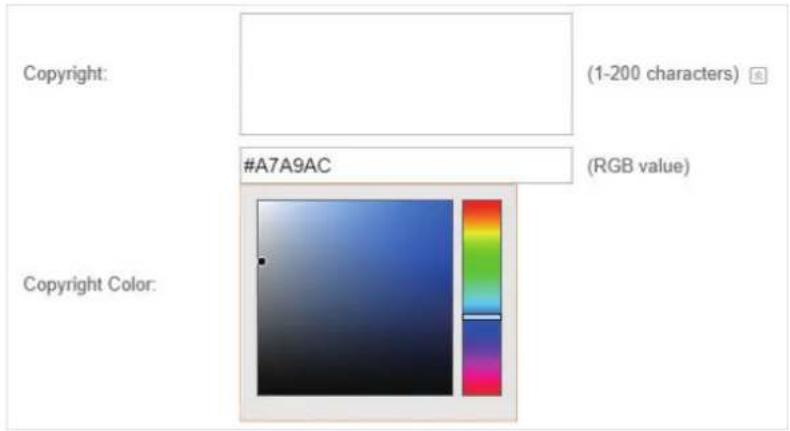
Terms of Service:
Enable or disable Terms of Service. With this option enabled, specify the terms of service in the following box.
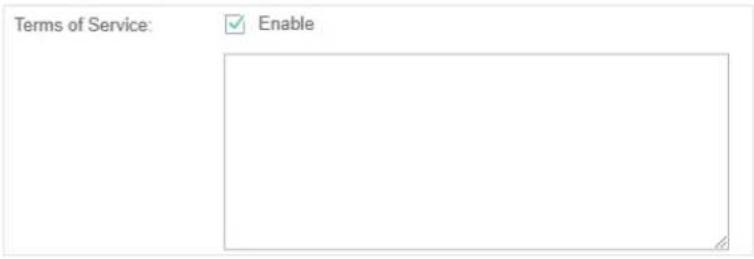
Input Box:
Click the dropdown arrow and configure the input box.
Select your desired color for the input box through the color picker or by entering the RGB value manually.

Button:
Click the clipboard icon and configure the button.
Button Position: Set the position of the login button. The options include Middle, Upper, and Lower.
Button Color: Select your desired login button color through the color picker or by entering the RGB value manually.
Button Text Color: Select your desired text color for the button through the color picker or by entering the RGB value manually.

- In the Advertisement section, select whether to display advertisement pictures for users and configure the related parameters.

Configure the following parameters:
| Advertisement | Specify whether to enable the Advertisement feature. With this feature enabled, you can add advertisement pictures on the authentication page. These advertisement pictures will be displayed before the login page appears. You can also allow users to skip the advertisement by enabling Allow Users To Skip Advertisement. The advertisement picture should be less than 2MB. And only JPG, PNG, BMP, GIF and JPEG file types are supported. |
| Picture Resource | Upload advertisement pictures. When several pictures are added, they will be played in a loop. |
| Advertisement Duration Time | Specify how long the advertisement will be displayed for. For this duration, the pictures will be played in a loop. If the duration time is not enough for all the pictures, the rest will not be displayed. |
| Picture Carousel Interval | Specify the picture carousel interval. For example, if this value is set as 5 seconds, the first picture will be displayed for 5 seconds, followed by the second picture for 5 seconds, and so on. |
| Allow Users To Skip Advertisement | Specify whether to enable this feature. With this feature enabled, the user can click theSkipbutton to skip the advertisement. |
5. Click Apply.
Create Vouchers
Follow the steps below to create vouchers for authentication:
- In the Basic Info section, click Voucher Manager. The voucher management page will appear. Go to the Voucher page and click Create Vouchers.

- The following window will pop up. Configure the required parameters and click Apply.

Configure the following parameters:
| Code Length Specify the length of the voucher codes to be created. | |
| Amount Enter the voucher amount to be generated. | |
| Type | Select Single Use or Multi Use.Single Use means one voucher can only be distributed to one client. Multi Use means one voucher can be distributed to several clients, who can use the same voucher to access the network at the same time.If you select Multi Use, enter the value of Max Users. When the number of clients who are connected to the network with the same voucher reaches the value, no more clients can use this voucher to access the network. |
| Duration Select the period of validity of the Voucher.The options include 8 hours, 2 days and User-defined. The period of valid of the voucher is reckoned from the time when it is used for the first time. | |
| Rate Limit (Download) | Select whether to enable download rate limit. With this option enabled, you can specify the limit of download rate. |
| Rate Limit (Upload) | Select whether to enable upload rate limit. With this option enabled, you can specify the limit of upload rate. |
| Traffic Limit | Specify the total traffic limit for one voucher. Once the limit is reached, the client can no longer access the network using the voucher. |
Notes: Enter a description for the Voucher (optional).
- The Vouchers will be generated and displayed on the page.

- Click to print a single voucher; click to print your selected vouchers; click Print All Unused Vouchers to print all unused vouchers.
| Valid for 8h with single use 838770 | Valid for 8h with single use 202209 | Valid for 8h with single use 306697 | Valid for 8h with single use 568081 |
| Valid for 8h with single use 637139 | Valid for 8h with single use 461670 | Valid for 8h with single use 172787 | Valid for 8h with single use 457410 |
| Valid for 8h with single use 191851 | Valid for 8h with single use 921414 |
- Distribute the vouchers to clients, and then they can use the codes to pass authentication.
- When the vouchers are invalid, you can click 📄 to delete the Voucher or click to Delete the selected vouchers.
Manage the Guests
On the Guest page, you can view the information of clients that have passed the portal authentication and manage the clients.

You can select an icon to execute the corresponding operation:

Restrict the client to access the network.

Extend the effective time.
Create Operator Accounts
Operator account can be used to remotely manage the Local User Portal and Voucher Portal. Other users can visit the URL https://Omada Controller Host's IP Address:8043/hotspot (For example: https://192.168.0.64:8043/hotspot) and use the Operator account to enter the portal management page.
Note:
- Make sure the host that is used to enter the portal management page with operator account can visit the Controller host.
- Only the user that log in to the controller with the administrator role can add or remove the operator account for portal management.
- The users who enter the portal management page by operator account can only create local user accounts and vouchers and manage the clients.
Follow the steps below to create Operator account.
- Go to the Operator page.

- Click and the following window will pop up.

- Specify the Name, Password and Notes of the Operator account.
- Select Site Privileges from the drop-down list (multiple options available) for the Operator account.
- Click Apply to create an Operator account. Then other users can use this account to enter the hotspot administrative system.
3.3.5 SMS
With SMS portal configured, client can get verification codes using their mobile phones and enter the received codes to pass the authentication.
Follow the steps below to configure SMS Portal:
- Go to www.twilio.com/try-twilio and get a Twilio account. Buy the Twilio service for SMS. Then get the account information, including ACCOUNT SID, AUTH TOKEN and Phone number.
- Go to Wireless Settings > Basic Wireless Settings and create an SSID for the Portal.
- Go back to the Portal configuration page. In the Basic Info section, complete the basic settings for the portal authentication.

Configure the following parameters:
| Portal Name Specify a name for the Portal. | |
| SSID Select an SSID for the Portal. | |
| Authentication Type Select SMS. | |
| Twilio SID Enter the Account SID for Twilio API Credentials. | |
| Auth Token Enter the Authentication Token for Twilio API Credentials. | |
| Phone Number Enter the phone number that is used to send verification messages to the clients. | |
| Maximum Users A telephone can get several codes via messages one by one, and different clients can use different codes to pass the authentication. However, the number of clients that is allowed to be authenticated using the same telephone at the same time has a upper limit.Specify the upper limit in this field. | |
| Authentication Timeout | The client's authentication will expire after the time period you set and the client needs to log in again on the web authentication page to access the network.Options include 1 Hour, 8 Hours, 24 Hours, 7 Days and Custom. Custom allows you to define the time in days, hours and minutes. The default value is one hour. |
| Preset Country Code | Set the default country code that will be filled automatically on the authentication page. |
| HTTPS Redirect With this function enabled, the unauthorized clients will be redirected to the Portal page when they are trying to browse HTTPS websites.With this function disabled, the unauthorized clients cannot browse HTTPS websites and are not redirected to the Portal page. | |
Redirect If you enable this function, the portal will redirect the newly authenticated clients to the configured URL.
Redirect URL
If the Redirect function above is enabled, enter the URL that a newly authenticated client will be redirected to.
- In the Login Page section, configure the login page for the Portal.

Configure the following parameters:
| Background | Select the background type. Two types are supported: Solid Color and Picture. |
| Background Color | If Solid Color is selected, configure your desired background color through the color picker or by entering the RGB value manually. |
| Background Picture | If Picture is selected, click the Choose button and select a picture from your PC. Drag and scale the clipping region to edit the picture and click Confirm. |
| Logo Picture | Click the Choose button and select a picture from your PC. Drag and scale the clipping region to edit the picture and click Confirm.In addition, you can click and configure the logo position. The options include Middle, Upper and Lower. |
Welcome Information Specify the welcome information.
In addition, you can click 📋 and select your desired text color for the welcome information through the color picker or by entering the RGB value manually.

Copyright: Specify the copyright information.
In addition, you can click 📋 and select your desired text color for Copyright information through the color picker or by entering the RGB value manually.

Terms of Service
Enable or disable Terms of Service. With this option enabled, specify the terms of service in the following box.

Input Box
Click ▼ and configure the input box.
Select your desired color for the input box through the color picker or by entering the RGB value manually.
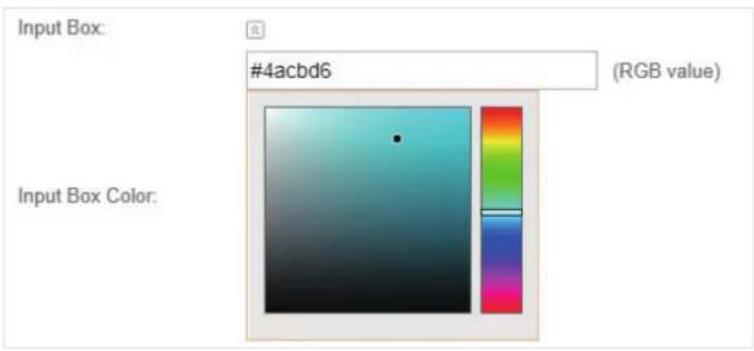
Button
Click 📋 and configure the button.
Button Position: Set the position of the login button. The options include Middle, Upper and Lower.
Button Color: Select your desired login button color through the color picker or by entering the RGB value manually.
Button Text Color: Select your desired text color for the button through the color picker or by entering the RGB value manually.

- In the Advertisement section, select whether to display advertisement pictures for users and configure the related parameters.

Configure the following parameters:
| Advertisement Specify whether to enable the Advertisement feature. With this feature enabled, you can add advertisement pictures on the authentication page. These advertisement pictures will be displayed before the login page appears. You can also allow users to skip the advertisement by enabling Allow Users To Skip Advertisement. The advertisement picture should be less than 2MB. And only JPG, PNG, BMP, GIF and JPEG file types are supported. | |
| Picture Resource | Upload advertisement pictures. When several pictures are added, they will be played in a loop. |
| Advertisement Duration Time | Specify how long the advertisement will be displayed for. For this duration, the pictures will be played in a loop. If the duration time is not enough for all the pictures, the rest will not be displayed. |
| Picture Carousel Interval | Specify the picture carousel interval. For example, if this value is set as 5 seconds, the first picture will be displayed for 5 seconds, followed by the second picture for 5 seconds, and so on. |
| Allow Users To Skip Advertisement | Specify whether to enable this feature. With this feature enabled, the user can click the Skip button to skip the advertisement. |
6. Click Apply.
For more details about how to configure SMS Portal, you can go to https://www.tp-link.com/en/configuration-guides.html and download the configuration guide for SMS Portal.
3.3.6 Facebook
With Facebook Portal configured, when clients connect to your Wi-Fi, they will be redirected to your Facebook page. To access the internet, clients need to pass the authentication on the page.
Note:
Omada Controller will automatically create Free Authentication Policy entries for the Facebook Portal. You don't need to create them manually.
Follow the steps below to configure Facebook Portal:
- Go to www.facebook.com and get a Facebook account. Create your Facebook page according to your needs.
- Go to Wireless Settings > Basic Wireless Settings and create an SSID for the Portal.
- Go back to the Portal configuration page. In the Basic Info section, complete the settings for the portal authentication.

Configure the following parameters:
| Portal Name Specify a name for the Portal. | |
| SSID Select an SSID for the Portal. | |
| Authentication Type Select Facebook. | |
| Facebook Page Configuration | Click this button to specify the Facebook Page. |
| Facebook Checkin Location | If the Facebook page is successfully got by the Omada Controller, the name of the Facebook page will be displayed here. |
| HTTPS Redirect With this function enabled, the unauthorized clients will be redirected to the Portal page when they are trying to browse HTTPS websites.With this function disabled, the unauthorized clients cannot browse HTTPS websites and are not redirected to the Portal page. | |
For more details about how to configure Facebook Portal, you can go to https://www.tp-link.com/en/configuration-guides.html and download the configuration guide for Facebook Portal.
3.3.7 External RADIUS Server
If you have a RADIUS server, you can configure External RADIUS Server Portal. With this type of portal, you can get two types of portal customization: Local Web Portal and External Web Portal. The authentication login page of Local Web Portal is provided by the built-in portal server of the controller. The External Web Portal is provided by external portal server.
Note:
Omada Controller will automatically create Free Authentication Policy entries for the External RADIUS Portal.
Follow the steps below to configure External RADIUS Server Portal:
- Go to Wireless Settings > Basic Wireless Settings and create an SSID for the Portal.
- Go back to the Portal configuration page. In the Basic Info section, complete the basic settings for the portal authentication.

Configure the following parameters:
| Portal Name Specify a name for the Portal. | |
| SSID Select an SSID for the Portal. | |
| Authentication Type | Select External RADIUS Server. |
| Authentication Timeout | The client's authentication will expire after the time period you set and the client needs to log in again on the web authentication page to access the network.Options include 1 Hour, 8 Hours, 24 Hours, 7 Days, Custom. Custom allows you to define the time in days, hours, and minutes. The default value is one hour. |
| RADIUS Server IP Enter the IP address of the RADIUS server. | |
| RADIUS Port Enter the port number you have set on the RADIUS server. | |
| RADIUS Password Enter the password you have set on the RADIUS server. | |
| Authentication Mode | Select the authentication protocol for the RADIUS server. Two authentication protocols are available: PAP and CHAP. |
| NAS ID Configure a Network Access Server Identifier (NAS ID) using 1 to 64characters on the portal. The NAS ID is sent to the RADIUS server by the controller through an authentication request packet. With the NAS ID which classifies users to different groups, the RADIUS server can send a customized authentication response. The default value is TP-Link. | |
| RADIUS Accounting Enable or disable RADIUS Accounting feature. | |
| Accounting Server IP Enter the IP address of the accounting server. | |
| Accounting Server Port Enter the port number of the accounting server. The default port number is 1813. | |
| Accounting Server Password | Enter the shared secret key of the accounting server. |
| Interim Update With this option enabled, you can specify the duration between accounting information updates. By default, the function is disabled.Enter the appropriate duration between updates for EAPs in Interim Update Interval. | |
| Interim Update Interval | With Interim Update enabled, specify the appropriate duration between updates for EAPs. The default duration is 600 seconds. |
| Portal Customization Select Local Web Portal or External Web Portal.Local Web Portal: If this option is selected, refer to step 3 to configure the login page and step 4 to configure the advertisement.External Web Portal: If this option is selected, follow the steps below.1. Configure the external RADIUS server.2. Enter the authentication login page's URL provided by the external portal server in the External Web Portal URL field.Note that you should update the External Web Portal after you upgrade your controller with old version to version 3.1.4 or above. Otherwise, the External Web Portal will not take effect. | |
| HTTPS Redirect With this function enabled, the unauthorized clients will be redirected to the Portal page when they are trying to browse HTTPS websites.With this function disabled, the unauthorized clients cannot browse HTTPS websites and are not redirected to the Portal page. | |
| Redirect If you enable this function, the portal will redirect the newly authenticated clients to the configured URL.It is disabled by default. | |
| Redirect URL If the Redirect function above is enabled, enter the URL that a newly authenticated client will be redirected to. | |
- If Local Web Portal is configured, configure the login page for the Portal in the Login Page section.

Configure the following parameters:
| Background | Select the background type. Two types are supported: Solid Color and Picture. |
| Background Color | If Solid Color is selected, configure your desired background color through the color picker or by entering the RGB value manually. |
| Background Picture | If Picture is selected, click the Choose button and select a picture from your PC. Drag and scale the clipping region to edit the picture and click Confirm. |
| Logo Picture | Click the Choose button and select a picture from your PC. Drag and scale the clipping region to edit the picture and click Confirm.In addition, you can click and configure the logo position. The options include Middle, Upper and Lower. |
Specify the welcome information.
In addition, you can click 📋 and select your desired text color for the welcome information through the color picker or by entering the RGB value manually.

Copyright: Specify the copyright information.
In addition, you can click 📋 and select your desired text color for Copyright information through the color picker or by entering the RGB value manually.

Terms of Service
Enable or disable Terms of Service. With this option enabled, specify the terms of service in the following box.

Input Box
Click ▼ and configure the input box.
Select your desired color for the input box through the color picker or by entering the RGB value manually.

Button
Click 📋 and configure the button.
Button Position: Set the position of the login button. The options include Middle, Upper and Lower.
Button Color: Select your desired login button color through the color picker or by entering the RGB value manually.
Button Text Color: Select your desired text color for the button through the color picker or by entering the RGB value manually.

- If Local Web Portal is configured, select whether to display advertisement pictures for users and configure the related parameters in the Advertisement section.

Configure the following parameters:
| Advertisement | Specify whether to enable the Advertisement feature. With this feature enabled, you can add advertisement pictures on the authentication page. These advertisement pictures will be displayed before the login page appears. You can also allow users to skip the advertisement by enabling Allow Users To Skip Advertisement. The advertisement picture should be less than 2MB. And only JPG, PNG, BMP, GIF and JPEG file types are supported. |
| Picture Resource | Upload advertisement pictures. When several pictures are added, they will be played in a loop. |
| Advertisement Duration Time | Specify how long the advertisement will be displayed for. For this duration, the pictures will be played in a loop. If the duration time is not enough for all the pictures, the rest will not be displayed. |
| Picture Carousel Interval | Specify the picture carousel interval. For example, if this value is set as 5 seconds, the first picture will be displayed for 5 seconds, followed by the second picture for 5 seconds, and so on. |
| Allow Users To Skip Advertisement | Specify whether to enable this feature. With this feature enabled, the user can click theSkipbutton to skip the advertisement. |
5. Click Apply.
3.3.8 External Portal Server
The option of External Portal Server is designed for the developers. They can customized their own authentication type according to the interface provided by Omada Controller, e.g. message authentication and WeChat authentication etc.
- Go to Wireless Settings > Basic Wireless Settings and create an SSID for the Portal.
- Go back to the Portal configuration page. In the Basic Info section, complete the settings for the portal authentication.
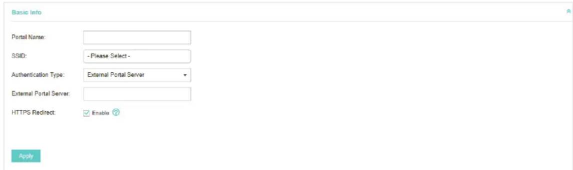
Portal Name: Specify a name for the Portal.
SSID: Select an SSID for the Portal.
| Authentication Type | Select External Portal Server. |
| External Portal Server | Enter the complete authentication URL that redirect to an external portal server, for example:http://192.168.0.147:8880/portal/index.php or http://192.168.0.147/portal/index.html |
HTTPS Redirect: With this function enabled, the unauthorized clients will be redirected to the Portal page when they are trying to browse HTTPS websites. With this function disabled, the unauthorized clients cannot browse HTTPS websites and are not redirected to the Portal page.
3. Click Apply.
3.4 Free Authentication Policy
Free Authentication Policy allows some specified clients to access the network resources without authentication. Follow the steps below to add free authentication policy.
- Go to Wireless Control > Free Authentication Policy.

- Click and the following window will pop up.

- Configure the following parameters. When all conditions are met, the client can access the network without authentication.
| Policy Name Specify a name for the policy. | |
| Match Mode Select the match mode for the policy. Two options are provided:URL: With this option selected, configure an URL that is allowed to be visited by the clients without authentication.IP-MAC Based: With this option selected, configure Source IP Range, Destination IP Range, Source MAC and Destination MAC to specify the specific clients and service that will follow the Free Authentication feature. | |
| URL Set the URL. | |
| Source IP Range Set the Source IP Range with the subnet and mask length of the clients. | |
| Destination IP Range | Set the Destination IP Range with the subnet and mask length of the server. |
| Source MAC Set the MAC address of client. | |
| Destination Port Enter the port the service uses. | |
| Status Check the box to enable the policy. | |
- Click Apply and the policy is successfully added.
3.5 MAC Filter
MAC filter can be used to allow or block the listed clients to access the network. Thereby it can effectively control the client's access to the wireless network.
Follow the steps below to configure MAC Filter.
- Go to Wireless Control > MAC Filter to add MAC Filter group and group members.

1) Click and specify a name for the group.

2) Click Apply and the group will be successfully added as shown below.

3) Click and enter a MAC address in the format as shown below.

4) Click Apply to add the MAC address into the MAC filter group.

- You can add more groups or members according to your need.
Note:
You can click to export the group members to an Excel file and save the file on your PC. If needed, you can also click Export Group Members to import the group members to the Omada Controller.
- Go to Wireless Control > MAC Filter Association to associate the added MAC Filter group with SSID.

1) Check the box and click Apply to enable MAC Filtering function. 2) Select a band frequency (2.4GHz or 5GHz) and a WLAN group. 3) In the MAC Filter Name column of the specified SSID, select a MAC Filter group in the dropdown list. Then select Allow/Deny in the Action column to allow/deny the clients in the MAC Filter group to access the network. 4) Click Apply in the Setting column.
3.6 Scheduler
With the Scheduler, the EAPs or their wireless network can automatically turn on or off at the time you set. For example, you can use this feature to schedule the radio to operate only during the office working time in order to achieve security goals and reduce power consumption. You can also use the Scheduler to make clients only access the wireless network during the time period you set in the day.
Follow the steps below to configure Scheduler.
- Go to Wireless Control > Scheduler.

1) Click and specify a name for the profile.

2) Click Apply and the profile will be added.

3) Click and configure the parameters to specify a period of time.

4) Click Apply and the profile is successfully added in the list.
- Go to Wireless Control > Scheduler Association.

1) Check the box to enable Scheduler function. 2) Select Associated with SSID (the profile will be applied to the specific SSID on all the EAPs) or Associated with AP (the profile will be applied to all SSIDs on the specific EAP). Then click Apply. 3) Select a band frequency (2.4GHz or 5GHz) and a WLAN group. 4) In the Profile Name column of the specified SSID or AP, select a profile you added before in the drop-down list. Select Radio Off/Radio On to turn off or on the wireless network during the time interval set for the profile. 5) Click Apply in the Setting column.
3.7 QoS
The Omada Controller software allows you to configure the quality of service (QoS) on the EAP for optimal throughput and performance when handling differentiated wireless traffic, such as Voice-over-IP (VoIP), other types of audio, video, streaming media, and traditional IP data.
To configure QoS on the EAP, you should set parameters on the transmission queues for different types of wireless traffic and specify minimum and maximum wait times (through contention windows) for transmission. In normal use, we recommend that you keep the default values for the EAPs and station EDCA (Enhanced Distributed Channel Access).
Follow the steps below to configure QoS.
1. Go to Wireless Control > QoS.

2. Enable or disable the following features.
| Wi-Fi Multimedia (WMM) | By default enabled. With WMM enabled, the EAPs have the QoS function to guarantee the high priority of the transmission of audio and video packets. If 802.11n only mode is selected in 2.4GHz (or 802.11n only, 802.11ac only, or 802.11 n/ac mixed mode in 5GHz), the WMM should be enabled. If WMM is disabled, the 802.11n only mode cannot be selected in 2.4GHz (or 802.11n only, 802.11ac only, or 802.11 n/ac mixed mode in 5GHz). |
| No Acknowledgment | By default disabled. You can enable this function to specify that the EAPs should not acknowledge frames with QoS No Ack. Enabling No Acknowledgment can bring more efficient throughput but higher error rates in a noisy Radio Frequency (RF) environment. |
| Unscheduled Automatic Power Save Delivery | By default enabled. As a power management method, it can greatly improve the energy-saving capacity of clients. |
- Click AP EDCA Parameters and the following page will appear. AP EDCA parameters affect traffic flowing from the EAP to the client station. We recommend that you use the defaults.

| Queue | Queue displays the transmission queue. By default, the priority from high to low is Data 0, Data 1, Data 2, and Data 3. The priority may be changed if you reset the EDCA parameters.Data 0 (Voice)—Highest priority queue, minimum delay. Time-sensitive data such as VoIP and streaming media are automatically sent to this queue.Data 1 (Video)—High priority queue, minimum delay. Time-sensitive video data is automatically sent to this queue.Data 2 (Best Effort)—Medium priority queue, medium throughput and delay. Most traditional IP data is sent to this queue.Data 3 (Background)—Lowest priority queue, high throughput. Bulk data that requires maximum throughput and is not time-sensitive is sent to this queue (FTP data, for example). |
| Arbitration Inter-Frame Space | A wait time for data frames. The wait time is measured in slots. Valid values for Arbitration Inter-Frame Space are from 0 to 15. |
| Minimum Contention Window | A list to the algorithm that determines the initial random backoff wait time (window) for retry of a transmission.This value can not be higher than the value for the Maximum Contention Window. |
| Maximum Contention Window | The upper limit (in milliseconds) for the doubling of the random backoff value. This doubling continues until either the data frame is sent or the Maximum Contention Window size is reached.This value must be higher than the value for the Minimum Contention Window. |
| Maximum Burst | Maximum Burst specifies the maximum burst length allowed for packet bursts on the wireless network. A packet burst is a collection of multiple frames transmitted without header information. The decreased overhead results in higher throughput and better performance. |
- Click Station EDCA Parameters and the following page will appear. Station EDCA parameters affect traffic flowing from the client station to the EAP. We recommend that you use the defaults.
| Queue | Arbitration Inter_Frame Space | Minimum Contention Window | Maximum Contention Window | TXOP Limit |
| Data 0(Voice) | 2 | 3 | 7 | 1504 |
| Data 1(Video) | 2 | 7 | 15 | 3008 |
| Data 2(Best Effort) | 3 | 15 | 1023 | 0 |
| Data 3(Background) | 7 | 15 | 1023 | 0 |
| Queue | Queue displays the transmission queue. By default, the priority from high to low is Data 0, Data 1, Data 2, and Data 3. The priority may be changed if you reset the EDCA parameters.Data 0 (Voice)—Highest priority queue, minimum delay. Time-sensitive data such as VoIP and streaming media are automatically sent to this queue.Data 1 (Video)—High priority queue, minimum delay. Time-sensitive video data is automatically sent to this queue.Data 2 (Best Effort)—Medium priority queue, medium throughput and delay. Most traditional IP data is sent to this queue.Data 3 (Background)—Lowest priority queue, high throughput. Bulk data that requires maximum throughput and is not time-sensitive is sent to this queue (FTP data, for example). |
| Arbitration Inter-Frame Space | A wait time for data frames. The wait time is measured in slots. Valid values for Arbitration Inter-Frame Space are from 0 to 15. |
| Minimum Contention Window | A list to the algorithm that determines the initial random backoff wait time (window) for retry of a transmission. This value can not be higher than the value for the Maximum Contention Window. |
| Maximum Contention Window | The upper limit (in milliseconds) for the doubling of the random backoff value. This doubling continues until either the data frame is sent or the Maximum Contention Window size is reached.This value must be higher than the value for the Minimum Contention Window. |
TXOP Limit
The TXOP Limit is a station EDCA parameter and only applies to traffic flowing from the client station to the EAP. The Transmission Opportunity (TXOP) is an interval of time, in milliseconds, when a WME client station has the right to initiate transmissions onto the wireless medium (WM) towards the EAP. The valid values are multiples of 32 between 0 and 8192.
5. Click Apply.
3.8 Site Settings
You can configure the site-specific settings on the Site Settings page. To switch sites, select a different site from the Sites drop-down menu at the top of any screen.

3.8.1 LED
You can change the LED light status on the EAPs on the page Site Settings > LED.

By default, the LED status is on, which means that the LED lights of all the EAPs on the site are on. You can click this button to change the LED light status. The icon will be changed to off, which means that all the LED lights are off.
3.8.2 Device Account
When the EAPs are adopted for the first time, their username and password will become the same as those of the Omada Controller which are specified at Basic Configurations. You can specify a new username and password for the adopted EAPs in batches.
Follow the steps below to change the username and password of EAPs.
- Go to Site Settings > Device Account.

- Specify a new username and password for the EAPs.
- Click Apply.
Note:
- The new account will be applied to EAPs but not the Omada Controller. To change the Omada Controller's username and password, please refer to User Account. • Device account can only be viewed and changed when you log in to the controller as the administrator. While the operator and observer accounts do not have the permission.
3.8.3 Reboot Schedule
You can reboot all the EAPs in the network periodically as needed. Follow the steps below to configure Reboot Schedule.
- Go to Site Settings > Reboot Schedule.

- Check the box to enable the function.
- Choose Daily, Weekly or Monthly in the Timing Mode drop-down list and set a specific time to reboot the EAPs.
- Click Apply.
3.8.4 Log Settings
Follow the steps below to choose the way to receive system logs.
- Go to Site Settings > Log Setting.
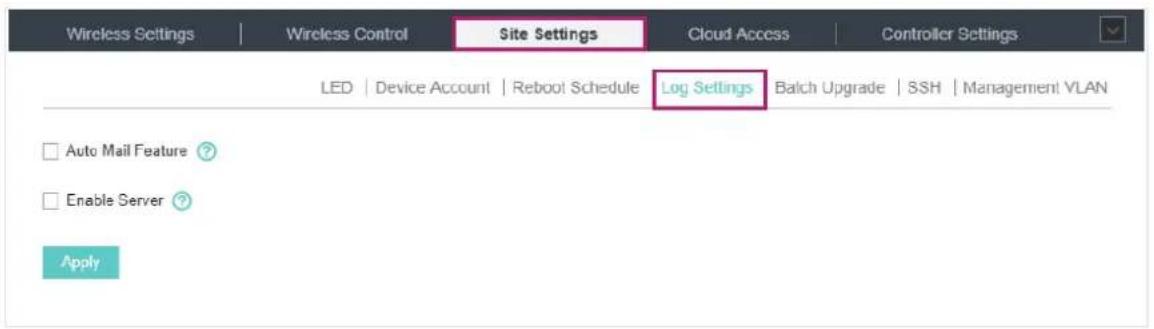
- Check the box to choose the ways to receive system logs and click Apply. Two ways are available: Auto Mail Feature and Server. You can choose more than one way.
Note:
The logs and alerts of the controller with version 3.0.5 or below will be discarded after the controller is upgraded to version 3.1.4 or above.
Auto Mail Feature
If Auto Mail Feature is enabled, system logs will be sent to a specified mailbox. Check the box to enable the feature and configure the parameters.

Receiver Address: Enter the receiver's E-mail address.
SMTP Server: Enter the IP address or domain name of the SMTP server.
| Port The SMTP server uses port 25 as default. If SSL is enabled, the port number will automatically change to 465. | |
| SSL You can check the box to enable SSL (Security Socket Layer) to enhance secure communications over the internet. | |
| Authentication | You can check the box to enable mail server authentication. Enter the sender's mail account name and password. |
| Username Enter the sender's mail account name. | |
| Password Enter the sender's mail password. | |
| Sender Address Enter the sender's E-mail address. | |
| Time Mode Select Time Mode. System logs can be sent at specific time or time interval. | |
Fixation Time: If you select Fixation Time, specify a fixed time to send the system log mails.
For example, 08:30 indicates that the mail will be sent at 8:30 am every day.

Period Time: If you select Period Time, specify a period time to regularly send the system
log mail. For example, 6 indicates that the mail will be sent every six hours.

Server
If Server is enabled, system logs will be sent to a server. Check the box to enable the feature and configure the parameters.
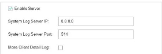
System Log Server IP: Enter the IP address of the server.
System Log Server Port: Enter the port of the server.
More Client Detail Log: With the option enabled, the logs of clients will be sent to the server.
3.8.5 Batch Upgrade
You can upgrade your EAPs of the same model in batches using Batch Upgrade. Two options are available for upgrading: upgrade online and upgrade manually.
Upgrade Online
With Cloud Access enabled, the latest firmware for the EAPs can be detected by the controller automatically. And you can upgrade the EAPs online. Thus you need not to save the firmware files locally in advance.
Follow the steps below to upgrade the EAPs online according to their model.
- Go to Cloud Access. Click the button to enable Cloud Access and log in and bind with your TP-Link ID. For more details about Cloud Access, please refer to Omada Cloud Service.
- Go to Site Settings > Batch Upgrade. The device model, amount, current firmware and available firmware will appear on the Firmware list.

- Click in the Action column to upgrade the device.
After upgrading, the device will reboot automatically.
Tips:
- You can click to check if the latest firmware is available.
- You can click ⓘ in the Available Firmware column to view the release note of the firmware, which can help you know the new features or improvements of this firmware.
Upgrade Manually
The latest firmware files can be downloaded in the download center of TP-Link Website. Then you can upgrade the EAPs manually.
Follow the steps below to upgrade the EAPs manually according to their model.
- Visit http://www.tp-link.com/en/support/download/ to download the latest firmware file of the corresponding model.
- Go to Site Settings > Batch Upgrade.

- Click in the Action column to upgrade the device.

- Click Browse to locate and choose the proper firmware file for the model.
- Click Upgrade to upgrade the device.
After upgrading, the device will reboot automatically.
Note:
- The EAP cannot be upgraded manually when you access the controller via Omada Cloud. • To avoid damage, please do not turn off the device while upgrading.
3.8.6 SSH
SSH is a protocol working in application layer and transport layer. It can provide a secure, remote connection to a device. After enabling SSH Login here, you can log in to the EAPs via SSH.
- Go to Site Setting > SSH. Enter the port number of the SSH server.

- Check the box to enable SSH Login. If you want to log in to the EAP from a different subnet via SSH, enable Layer-3 Accessibility.
- Click Apply.
3.8.7 Management VLAN
Management VLAN provides a safer way for you to manage the EAP. With Management VLAN enabled, only the hosts in the management VLAN can manage the EAP. Since most hosts cannot process VLAN tags, connect the management host to the network via a switch, and set up correct VLAN settings for the switches on the network to ensure the communication between the host and the EAP in the management VLAN.
Follow the steps below to configure Management VLAN.
- Go to Site Setting > Management VLAN. Check the box to enable Management VLAN.

- Specify the Management VLAN ID. The default VLAN ID is 1.
- Click Apply.
4 Omada Cloud Service
TP-Link Omada Cloud Service provides a better way to realize remote management. With Cloud Access enabled on the controller and a TP-Link ID bound with your controller, you can easily monitor and manage your wireless network. To ensure that your EAPs stay new and get better over time, the Omada Cloud will notify you when a newer firmware upgrade is available. Surely you can also manage multiple Omada Controllers with a single TP-Link ID.
Follow the steps below to configure Cloud Access and access the controller via Omada Cloud:
- Configure the Cloud Access
- Manage the Controller via Omada Cloud
4.1 Configure the Cloud Access
4.1.1 Enable Cloud Access
You can configure the controller via Omada Cloud only when Cloud Access is enabled on the controller and you have been added as a Cloud User.
On the Cloud Access page, you can configure Cloud Access. Click the button to enable Cloud Access. The Cloud Access status is ☐, which means that Cloud Access is enabled.

4.1.2 Manage the Cloud Users
To configure and manage the Omada Controller through the Cloud service, you need to have a TP-Link ID and bind your TP-Link ID to the controller. Then you can remotely access the controller as a Cloud User.
Note:
To register a TP-Link ID and bind it to your controller, make sure that the controller host can access the internet.
Register a TP-Link ID
In the Quick Setup process, you can register a TP-Link ID and bind it to your controller. If you skipped the registration during the Quick Setup process, you can go to Cloud Access. Click Register Now and follow the instructions to register a TP-Link ID.

Log in and bind your TP-Link ID
After activating your TP-Link ID, come back to the Cloud Access page to log in and bind your TP-Link ID to your controller.

The TP-Link ID that is bound with the controller for the first time will be automatically bound as an administrator. Only one TP-Link ID can be bound with the controller as an administrator. An administrator account can add or remove other TP-Link IDs to or from the same controller as Cloud Users.

Add new Cloud Users
After you have an administrator TP-Link ID, you can add new Cloud Users. Click , enter another TP-Link ID as needed, and click Save.
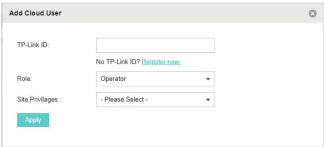
| TP-Link ID | Enter the TP-Link ID that you want to add as the new Cloud User. If you do not have another TP-Link ID, you can clickRegister Nowand follow the instructions to register a TP-Link ID. |
| Role Select the role for the new Cloud User from the drop-down list. Two options are provided:Operator: An Operator account can change the settings of the privileged sites that are given by the administrator. And the Operator account cannot manage the cloud users and change controller settings.Observer: An Observer account can only view the status and settings of the privileged sites that are given by the administrator but not change the settings.Both the Operator and Observer accounts cannot manage the cloud users and controller settings. Thus Operator and Observer accounts can only be created or deleted by the administrator. | |
| Site Privileges | Select the privileged sites (multiple options available) for the Operator or Observer accounts from the drop-down list. |
Unbind a TP-Link ID
You can click Unbind to unbind your administrator TP-Link ID. Note that the Unbind operation cannot be performed when you log in to the controller through Omada Cloud service.

4.2 Manage the Controller via Omada Cloud
With Cloud Access enabled, you can manage your controller remotely using your TP-Link ID. You can refer to the following topology.
![graph TD A["Switch"] --> B["Controller Host"] B --> C["Omada Controller"] B --> D["Router"] D --> E["EAPs"] D --> F["Internet"] F --> G["Management Devices"] B --> H["Clients"] style A fill:#f9f,stroke:#333 style D fill:#f9f,stroke:#333 style G fill:#ccf,stroke:#333](/content/2026/06/1336671/images/26e18d8e0d12f8b890e0efe7ad888c649043aae0d19aab535f0a8c20c71a0706.jpg)
Before you remotely access your controller, make sure that the following requirements have been met:
■ Cloud Access is enabled on the controller. - Your controller has been bound with a TP-Link ID. If you don't have a TP-Link ID, refer to Register a TP-Link ID to get one. ■ Both your Controller Host and management devices have internet access.
4.2.1 Access the controller via Omada Cloud
- Launch a web browser and type https://omada.tplinkcloud.com in the address bar, then press Enter (Windows) or Return (Mac).


https://omada.tplinkcloud.com
- Enter your TP-Link ID and password and click Log In.

- After you log in to Omada Cloud, a list of controllers that have been bound with your TP-Link ID will appear. If the controller does not appear on the list, you can click 🔒 to refresh the current page.
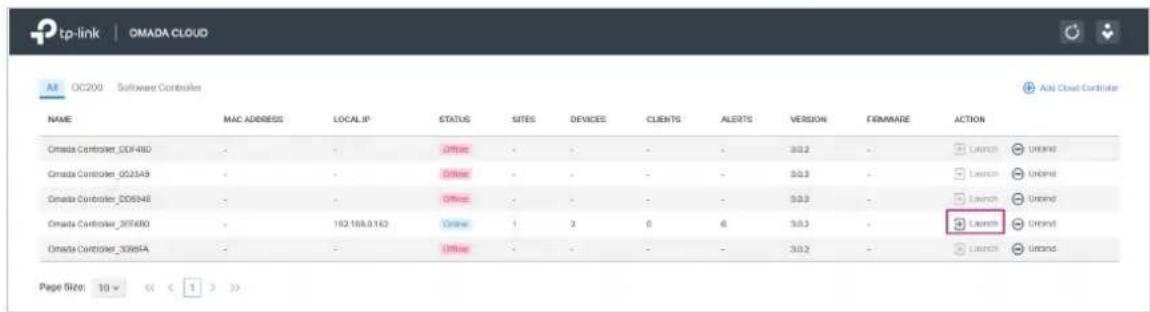
Click Launch to access your controller. Then you can configure and manage your controller.

Note:
- To refresh the page, click 📊. Automatic refreshing is not available when accessing the controller via Omada Cloud.
• To remove the Omada Controller from your cloud account, you can click ☑ Unbind.
• To log out of Omada Cloud, click and select Log Out.
4.2.2 Change your TP-Link ID information
You can change your TP-Link ID information on the Omada Cloud page. Click the user icon and select My TP-Link ID, the cloud account settings will appear.
You can have a nickname for your TP-Link ID. Enter your nickname and click Save.

You can also change the password of your TP-Link ID. Enter the current password, then a new password twice and click Save.

5 Configure the EAPs Separately
In addition to global configuration, you can configure the EAPs separately and the configuration results will be applied to a specified EAP.
To configure a specified EAP, click the EAP's name on the Access Points tab or click the connected EAP on the map. Then you can view the EAP's detailed information and configure the EAP in the pop-up window.
This chapter includes the following contents:
■ View the Information of the EAP ■ View Clients Connecting to the EAP ■ View Mesh Information of the EAP ■ Configure the EAP
5.1 View the Information of the EAP
5.1.1 Active Channel Information
The active channel information on each radio band will be displayed in a bar graph, which indicates its percentages of the following: Rx Frames (blue), Tx Frames (green), Interference (orange), and Free bandwidth (gray). The percentage of channel utilization is also displayed with the corresponding evaluation.
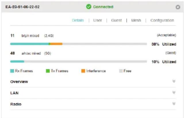
You can click a point on either bar graph for more details:
| Tx Pkts/Bytes | 5730951 / 1.11 G |
| Rx Pkts/Bytes | 39200052 / 8.72 G |
| Tx Error/Dropped | 0.0% / 0.0% |
| Rx Error/Dropped | 0.0% / 0.0% |
| Ch.Util.(Busy/Rx/Tx) | 38% / 28% / 1% |
| Tx Pkts/Bytes Displays the amount of data transmitted as packets and bytes. | |
| Rx Pkts/Bytes Displays the amount of data received as packets and bytes. | |
| Tx Error/Dropped Displays the percentage of transmit packets that have errors and thepercentage of packets that were dropped. | |
| Rx Error/Dropped | Displays the percentage of receive packets that have errors and thepercentage of packets that were dropped. |
| Ch.Util.(Busy/Rx/Tx) Displays channel utilization statistics. | |
| Busy: This number is the sum of Tx, Rx, and also non-WiFi interference, whichindicates how busy the channel is. | |
| Rx: This number indicates how often the radio is in active receive mode. | |
| Tx: This number indicates how often the radio is in active transmit mode. | |
5.1.2 Overview
Click Overview to view the basic information of the EAP which includes EAP's MAC address (or name you set), IP address, model, firmware version, the usage rate of CPU and Memory and uptime (indicates how long the EAP has been running without interruption).

5.1.3 LAN
Click LAN to view the traffic information of the LAN port, including the total number of packets, the total size of data, the total number of packets lost, and the total size of error data in the process of receiving and transmitting data.

5.1.4 Radio
Click Radio to view the radio information including the frequency band, the wireless mode, the channel width, the channel, and the transmitting power. You can also view parameters of receiving/transmitting data on each radio band.

5.2 View Clients Connecting to the EAP
5.2.1 User
The User page displays the information of clients connecting to the SSID with Portal disabled, including their MAC addresses and connected SSIDs. You can click the client's MAC address to get its connection history.

5.2.2 Guest
The Guest page displays the information of clients connecting to the SSID with Portal enabled, including their MAC addresses and connected SSIDs. You can click the client's MAC address to get its connection history.

5.3 View Mesh Information of the EAP
The Mesh page is used to view and configure the mesh parameters of the EAP.
5.3.1 Uplinks
Here you can view the parameters of the uplink APs or click to change the uplink AP.

Tips:
- You can click to search the available uplink APs and the Uplink list will refresh.
- To build a mesh network with better performance, we recommend that you select the Uplink AP with the strongest signal, least hop and least Downlink AP.
5.3.2 Downlinks
Here you can view the downlink APs.

5.4 Configure the EAP
The Configuration page is used to configure the EAP. All the configurations will only take effect on this device.
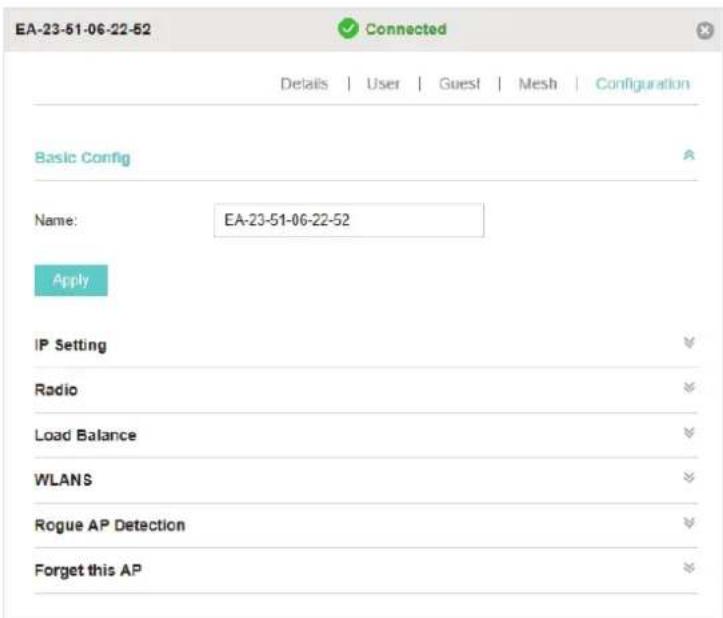
5.4.1 Basic Config
Here you can change the name of the EAP.

5.4.2 IP Setting
You can configure an IP address for this EAP. Two options are provided: DHCP and Static.

Get a Dynamic IP Address From the DHCP Server
- Configure your DHCP server.
- Select DHCP on the page above.
- Enable the Fallback IP feature. When the device cannot get a dynamic IP address, the fallback IP address will be used.
- Set IP address, IP mask and gateway for the fallback address and click Apply.
Manually Set a Static IP Address for the EAP
- Select Static.
- Set the IP address, IP mask, and gateway for the static address, then click Apply.
5.4.3 Radio
Radio settings directly control the behavior of the radio in the EAP and its interaction with the physical medium; that is, how and what type of signal the EAP emits.

Select the frequency band (2.4GHz/5GHz) and configure the following parameters.
| Status Enabled by default. If you disable the option, the radio on the frequency band will turn off. | |
| Mode Select the IEEE 802.11 mode the radio uses.When the frequency of 2.4GHz is selected, 802.11b/g/n mixed, 802.11b/g mixed, and 802.11n only modes are available:802.11b/g/n mixed: All of 802.11b, 802.11g, and 802.11n clients operating in the 2.4GHz frequency can connect to the EAP. We recommend that you select the 802.11b/g/n mixed mode.802.11b/g mixed: Both 802.11b and 802.11g clients can connect to the EAP.802.11n only: Only 802.11n clients can connect to the EAP.When the frequency of 5GHz is selected, 802.11 n/ac mixed, 802.11a/n mixed, 802.11 ac only, 802.11a only, and 802.11n only modes are available:802.11n/ac mixed: Both 802.11n clients and 802.11ac clients operating in the 5GHz frequency can connect to the EAP.802.11a/n mixed: Both 802.11a clients and 802.11n clients operating in the 5GHz frequency can connect to the EAP.802.11ac only: Only 802.11ac clients can connect to the EAP.802.11a only: Only 802.11a clients can connect to the EAP.802.11n only: Only 802.11n clients can connect to the EAP. | |
| Channel Limit | For the EAPs that support DFS in EU version, there is a Channel Limit option. If you want to use your EAP outdoors, enable this option to comply with the laws in your country. |
| Channel Width | Select the channel width of the EAP. The available options differ among different EAPs.For some EAPs, available options include 20MHz, 40MHz and 20/40MHz.For other EAPs, available options include 20MHz, 40MHz, 80MHz and 20/40/80MHz.The 20/40 MHz and 20/40/80MHz channels enable higher data rates but leave fewer channels available for use by other 2.4GHz and 5GHz devices. When the radio mode includes 802.11n, we recommend that you set the channel bandwidth to 20/40 MHz or 20/40/80MHz to improve the transmission speed. |
| Channel Select the channel used by the EAP to improve wireless performance. The range of available channels is determined by the radio mode and the country setting. If you select Auto for the channel setting, the EAP scans available channels and selects a channel where the least amount of traffic is detected. | |
| Tx Power (EIRP) | Select the Tx Power (Transmit Power) in the 4 options: Low, Medium, High and Custom. Low, Medium and High are based on the Min. Txpower (Minimum transmit power) and Max. TxPower (Maximum transmit power. It may vary among different countries and regions).Low: Min. TxPower + (Max. TxPower-Min. TxPower) * 20% (round off the value)Medium: Min. TxPower + (Max. TxPower-Min. TxPower) * 60% (round off the value)High: Max. TxPowerCustom: Enter a value manually. |
5.4.4 Load Balance
By setting the maximum number of clients accessing the EAPs, Load Balance helps to achieve rational use of network resources.

Select the frequency band (2.4GHz/5GHz) and configure the parameters.
| Max Associated Clients | Enable this function and specify the maximum number of connected clients. While more clients requesting to connect, the EAP will disconnect those with weaker signals. |
5.4.5 WLANs
You can specify a different SSID name and password to override the previous SSID. After that, clients can only see the new SSID and use the new password to access the network. Follow the steps below to override the SSID.

- Select the WLAN group.
- Click ☑ and the following window will pop up.

- Check the box to enable the feature.
- You can join the overridden SSID into a VLAN. Check the Use VLAN ID box and specify a VLAN ID.
- Specify a new name and password for the SSID.
- Click Apply to save the configuration.
5.4.6 LED
You can change the LED status of each EAP.
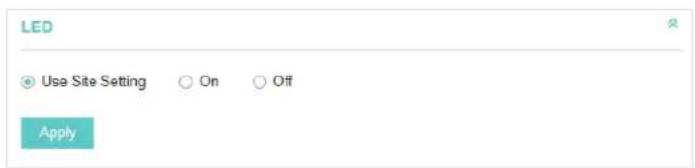
Using Site Setting The LED status will be the same as the site settings.
On Turn on the LED.
Off Turn off the LED.
5.4.7 Trunk Settings (Only for EAP330)
The trunk function can bundle multiple Ethernet links into a logical link to increase bandwidth and improve network reliability.
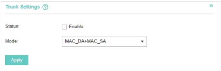
Status Enable this function.
The EAP330 has two 1000Mbps Ethernet ports. If the Trunk function is enabled and the ports are in the speed of 1000Mbps Full Duplex, the whole bandwidth of the trunk link is up to 4Gbps (2000Mbps * 2).
Mode Select the applied mode of Trunk Arithmetic from the drop-down list.
MAC_DA+MAC_SA: When this option is selected, the arithmetic will be based on the source and destination MAC addresses of the packets.
MAC_DA: When this option is selected, the arithmetic will be based on the destination MAC addresses of the packets.
MAC_SA: When this option is selected, the arithmetic will be based on the source MAC addresses of the packets.
5.4.8 Rogue APs Detection
With this option enabled, the EAP will detect rogue APs in all channels. You can view the results in the Insight > Untrusted Rogue APs page.

Note:
For some specific versions of the firmware, some EAPs will detect rogue APs automatically when this option is enabled.
5.4.9 Local LAN Port Settings (Only for EAP115-Wall and EAP225-Wall)
You can configure the LAN port of the EAP.

VLAN: Enable this feature and specify the VLAN that the EAP is added to, and then the hosts connected to this EAP can only communicate with the devices in this VLAN. The valid values are from 1 to 4094, and the default is 1.
PoE Out: If your EAP has a PoE OUT port, you can enable this option to supply power to the connected device on this port. The EAP that has no PoE OUT port does not support this feature.
5.4.10 Forget this AP
If you no longer want to manage this EAP, you may remove it. All the configurations and history about this EAP will be deleted. It is recommended to back up the configurations of this EAP before you forget it.

6
Manage the Omada Controller
This chapter mainly introduces how to manage the user account and configure system settings. This chapter includes the following contents.
■ User Account ■ General Setting ■ History Data Retention ■ Backup & Restore ■ Auto Backup ■ Migrate ■ Information About the Software
6.1 User Account
You can use different user roles to log in to the Omada Controller. There are three user roles: administrator, operator, and observer. The administration authority varies among different roles.
| Administrator | The first administrator account is created in the Basic Configuration process and this account can not be deleted. An administrator can change the settings of the EAP network and create and delete user accounts. |
| Operator An operator account can be created or deleted by the administrator. The operator can change the settings of the EAP network. | |
| Observer An observer account can be created or deleted by the administrator. The observer can only view the status and settings of the EAP network but not change the settings. | |
Follow the steps below to add a user account.
- Go to Controller Settings > User Account.

- Click and the following window will pop up.

- Specify the username, Email and password of the account.
- Select the role from the drop-down list.
■If you select operator or observer, you also need to select the Site Privileges.
■If you select administrator, the Site Privileges option will not appear and all sites are available for the administrator user.
- Click Apply to add the user account.
Note:
- You can refer to the Role page to view the user role's type, description information, permission scope and created time.
- The user account cannot be used to log in to the Omada Controller through Omada Cloud Service. To access the controller via Cloud Access, you should be a cloud user. To add a cloud user, refer to manage the cloud users
6.2 General Setting
6.2.1 Configure Controller Name
Omada Controller is given a default name in the format Omada Controller_XXXXXX. You can give your controller a descriptive name in the Controller Settings > General Setting page and click Apply.

6.2.2 Configure Mail Server
With the Mail Server, you can reset the login password of the user account if necessary. An email with the link for resetting the password will be sent from the Omada Controller. This is different from the SMTP Server, which is only used for sending system log emails.
Follow the steps below to configure the mail server.
- Go to Controller Settings > General Setting and click Mail Server.

- Enter the hostname or IP address of the Omada Controller. The default IP address of the Omada Controller is 127.0.0.1. You can keep it or customize the hostname or IP address that can be visited by the Controller host.
When the email with the link for resetting the password is sent out, the Controller hostname or IP address will be specified in the Controller URL in every message.
- Check the box to enable SMTP Server, and then the following screen will appear.

4. Configure the following parameters.
| Mail Server Enter the IP address or domain name of SMTP Server. | |
| Port The SMTP server uses port 25 as default. | |
| You can enable SSL (Security Socket Layer) to enhance secure communications over the Internet. If SSL is enabled, the port number will automatically change to 465. | |
| Enable Auth Check the box to enable authentication (Optional). | |
| Username/Password | If you enable authentication, enter the username and password required by the mail server. |
| Specify Sender Address | Specify the sender's mail address. Enter the email address that will appear as the sender for resetting password. |
5. Click Apply to save the configuration.
Note:
Specify the account email address based on the Mail server to receive the email for resetting the password.
6.3 History Data Retention
History Data Retention allows users to determine the retention of logs and client statistics. The logs and client statistics beyond the specified number of days will be cleared. For example, with 7 days selected, only the logs and client statistics from the recent 7 days will be retained, and the data beyond 7 days will be cleared from the controller.
Follow the steps below to configure Historical Data Retention:
1. Go to Controller Settings > History Data Retention.

- Select the length of time in days that data will be retained from the drop-down list. Seven options are provided: 7 days, 30 days, 60 days, 90 days, 180 days, 365 days, or All time.
- Click Apply.
6.4 Backup & Restore
You can save the current configuration and data in the controller as a backup file and, if necessary, restore the configuration using the backup file. We recommend that you back up the settings before upgrading the device. This function is available only for locally logged-in users.
Follow the steps below to back up and restore the configuration.
- Go to Controller Settings > Backup & Restore.

- Select the length of time in days that data will be backed up in the Retained Data Backup drop-down list. For example, with 7 days selected, only the data from the recent 7 days will be backed up.
- Click Backup to save the backup file.
- If necessary, click Browse to locate and choose the backup file. Then click Restore to restore the configuration.
Note:
- If you do not want to back up historical data, you can select Settings only to save only the controller settings in the backup files.
- If you do not want to back up data manually, you can enable the Auto Backup function. Please refer to Auto Backup.
- To keep the backup data safe, please wait without performing any operations while restoring the backup file.
6.5 Auto Backup
With Auto Backup enabled, the controller will be scheduled to back up the configuration and data automatically at the specified time.
Follow the steps below to configure the Auto Backup function.
- Go to Controller Settings > Auto Backup.

- Check the box to enable Auto Backup function.
- Select how often to perform Auto Backup in the Occurrence. You can choose Daily, Weekly, Monthly or Yearly from drop-down list. Then set an appropriate time to back up files in the Backup Time.
Note: When you choose the Occurrence as Monthly, please carefully choose the backup date in Backup Time. For example, if you choose to automatically backup the data on the 31th day of every month. When it comes to June, which is only 30 days long, the auto backup will not take effect
- Select the length of time in days that data will be backed up in the Retained Data Backup. For example, with 7 days selected, the data only in recent 7 days will be backed up.
- Specify the maximum number of backup files to save in the Maximum Number of Files. The default is 7.
You can view the name, backup time and size of the backup files in the Backup Files List.

You can execute the corresponding operation to the backup files by clicking an icon in the Action column.

Restore the data and configurations in the backup file.

Download the backup file.

Delete the backup file.
Note:
- To back up data manually and restore the data to the controller, configure Backup&Restore function. Please refer to Backup&Restore
- If you do not want to back up historical data, you can select Settings only to get only the controller setting saved in the backup files.
- The auto backup files will be stored in data/ autobackup folder of the controller installation location.
- The configuration of the cloud users will not be backed up. Thus the configuration of the cloud users cannot be restored. To add cloud users, please refer to Manage the Cloud Users. • To keep the backup data safe, please wait without any operations while restoring the backup file.
6.6 Migrate
The Migrate function allows users to migrate the configurations and data to any other site or controller.
For migrating all the configurations and data from the current controller to any other controller, refer to Controller Migrate.
For migrating the configurations and data from the existing site to any other controller, refer to Site Migrate.
6.6.1 Controller Migrate
With the Controller Migrate function, you can migrate your configurations and data from the current controller to any other controller that has the same or higher version.
The process of migrating configurations and data from the current controller to another controller can be summarized in three steps: Export Controller, Migrate Controller, and Migrate Devices.
Follow the steps below to migrate your controller.
Note:
- The connection to the internet will be lost for several minutes during the migration. Clients need to connect to the wireless network again after the migration is completed. Please choose the time to start the migration operation carefully.
- Exporting Controller and Migrating Controller are available only for local logged-in users.
■ Export Controller
1. Go to Controller Settings > Migrate > Controller Migrate.

- Select the length of time in days that data to be imported into the second controller in the Retained Data Backup drop-down list. For example, with 7 days selected, only the data from the recent 7 days will be imported into the second controller.
- Click Download Backup File to download the file of the current controller. If you have backed up the file, click Skip.
■Migrate Controller
- Start and log in to the second controller, go to Controller Settings > Backup&Restore > Restore File.

- Click Browse to locate and choose the file of your controller to be imported. Then click Restore to upload the file.
- After the file has been restored to the second controller, go back to the export controller and click Confirm.

■Migrate Devices
- Enter the IP address or URL of your second controller into Controller URL/IP input filed. In this case, the IP address of the second controller is 10.0.3.23.

Note:
Make sure that you enter the correct IP address of the second controller to establish the communication between EAPs and your second controller. Otherwise the EAPs cannot be adopted by the second controller.
- Select the devices that are to be migrated by clicking the boxes next to each device. By default, all the devices are selected.

- Click Migrate Devices to migrate the selected devices to the second controller.
- Verify that all the migrated devices are visible and connected on the second controller. Note that this may take several minutes. When all the migrated devices are in Connected status on the Access Points page on the second controller, click Forget Devices to finish the migration process.
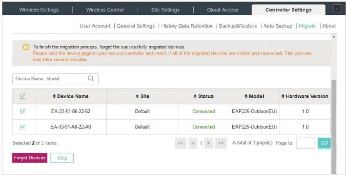
When the migration process is completed, all the configuration and data are migrated to the second controller. You can uninstall the previous controller if necessary.
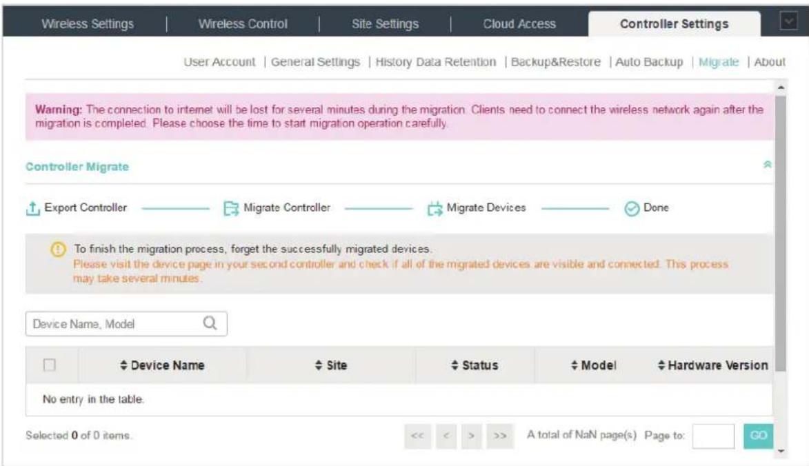
6.6.2 Site Migrate
With Site Migrate function, you can migrate your configurations and data of a site to any other controller that has the same version.
The process of migrating configurations and data from a site to another controller can be summarized in three steps: Export Site, Migrate Site, and Migrate Devices.
Follow the steps below to migrate a site to another controller.
Note:
The connection to the internet will be lost for several minutes during the migration. Clients need to connect to the wireless network again after the migration is completed. Please choose the time to start the migration operation carefully.
■ Export Site
- Go to Controller Settings > Migrate > Site Migrate.
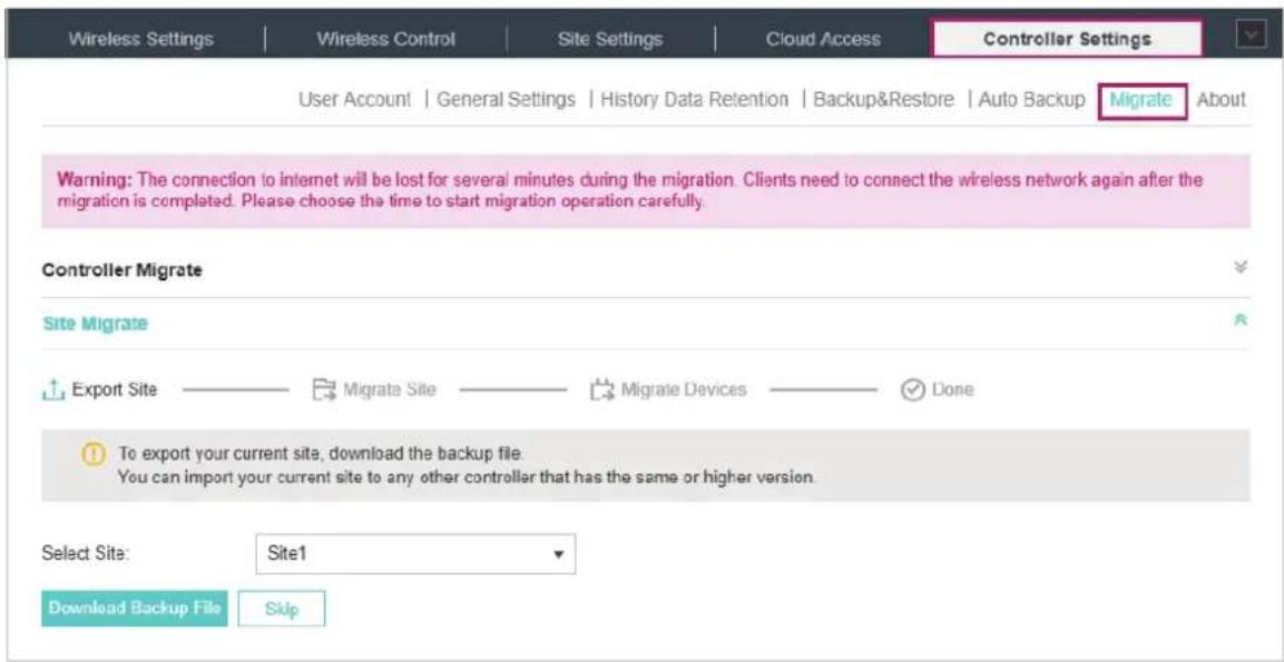
- Select the site to be imported into the second controller in the Select Site drop-down list.
- Click Download Backup File to download the file of the current site. If you have backed up the file, click Skip.
■ Migrate Site
- Start and log in to the second controller, click Sites: Default in the top left corner of the page and select Site Manager, and then the following window will pop up.

- Click and enter a unique name for the new site.

- Click Browse to upload the file of the site to be imported and click Import to import the site.

- After the file has been imported to the second controller, go back to the export controller and click Confirm.

■ Migrate Devices
- Enter the IP address or URL of your second controller into the Controller URL/IP input field. In this case, the IP address of the second controller is 10.0.3.14.

Note:
Make sure that you enter the correct IP address of the second controller to establish the communication between EAPs and your second controller. Otherwise the EAPs cannot be adopted by the second controller.
- Select the devices that are to be migrated by clicking the boxes next to each device. By default, all the devices are selected.

- Click Migrate Devices to migrate the selected devices to the second controller.
- Verify that all the migrated devices are visible and connected on the second controller. Note that this may take several minutes. When all the migrated devices are in Connected status on the Access Points page on the second controller, click Forget Devices to finish the migration process.

When the migration process is completed, all the configuration and data are migrated to the second controller. You can delete the previous site if necessary.

6.7 Information About the Software
You can view the Omada Controller's version and copyright information on the Controller Settings > About page.

7 Application Example
A restaurant has a wireless network with three EAPs managed by the Omada Controller. The network administrator wants to:
■ Monitor the EAPs with the Map. ■ Enable Portal function to drive customers' attention to the ads of the supermarket when customers attempt to access the network. The customers need to use a simple password to pass the authentication. ■ Allow the employees of the restaurant to access the network resources without portal authentication. ■ Schedule the radio to operate only during the working time (8:00 am to 22:00 pm) in order to reduce power consumption.
Follow the steps below to achieve the requirements above.
7.1 Basic Configuration
Follow the steps below to do the basic configuration.
- Connect the hardware by referring to the following topology.
![graph TD A["Host A (Controller Host)<br>IP: 192.168.0.100"] --> B["Omada Controller"] B --> C["Switch"] C --> D["Router (DHCP Server)<br>LAN IP:192.168.0.1"] D --> E["Internet"] C --> F["EAPs"] C --> G["EAPs"]](/content/2026/06/1336671/images/6f73e0a96d11389135e67d71dce223b78e0f1e8bf77877e290e4da1e4c91ea0a.jpg)
- Install the Omada Controller on Host A.
- Launch the software and follow the instructions to complete some initial configurations.
- Log into the management interface.
- Adopt the pending EAPs.
7.2 Advanced Settings
After the basic configuration, refer to the following content to meet the network administrator's requirements.
7.2.1 Monitor the EAPs with Map
Follow the steps below to create a map and monitor the EAPs with the map.
- Go to the Map.
- Import a local map and set the map scale.
- Drag the EAPs to the appropriate locations on the map.
- Click Coverage and you can see the representation of the EAPs' wireless coverage.

7.2.2 Configure Portal Authentication
Follow the steps below to configure Portal function.
- Go to Wireless Settings > Basic Wireless Settings and edit the SSID we created in the basic configuration.

To make it easier for customers to connect, change the Security Mode from WPA-PSK to None. Customers can connect to the EAPs without a password and be redirected to the Portal Authentication where the correct password will be required.
- Open the global configuration window and go to Wireless Control > Portal. Click, and the configuration window will pop up.

Add a New Portal
- In the Basic Info section, complete the basic settings for the portal.

1) Specify a name for the portal. 2) Select an SSID for the portal. 3) Select the Authentication Type as Simple Password. Specify a simple password for the guests. 4) Select the Authentication Timeout. For example, 1 Hour is suitable for the customers at the restaurant. 5) Enable the Redirect to drive the customers to the restaurant's homepage after successful login. We can put some promotion information on the page.
- In the Login Page section, configure the login page.

- In the Advertisement section, upload two pictures of the restaurant and set the related parameters.

- Click Apply.
7.2.3 Create an SSID for the Employees
We have created an SSID in the basic configuration for the customers. Here we need to create another SSID for the employees to allow them to access the network without portal authentication. In addition, the new SSID should be invisible to the customers.
Follow the steps below to create an SSID for the employees.
- Open the global configuration window and go to Wireless Settings > Basic Wireless Settings.
- Click Add to add a new SSID.

Configure the parameters.
1) Disable the SSID Broadcast to hide this SSID from the customers. 2) Specify the SSID Name, Security Mode, and Wireless Password. Let the employees manually enter the SSID name and password, and choose the security mode you set to access the network. 3) Click Apply to save the configuration.
7.2.4 Configure Scheduler
Follow the steps below to schedule the radio to operate only during the working time (from 8:00 to 22:00).
- Open the global configuration window and go to Wireless Control > Scheduler.
1) Add a profile.

2) Add an item for the profile. The parameters are set as shown on the following screen.
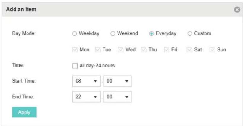
- Go to Scheduler Association tab.

1) Enable the function and select Associated with SSID. Click Apply. 2) In the Profile Name column of both SSIDs, select the profile we just created. 3) In the Action column of both SSIDs, select Radio On. 4) Click Apply in the Setting column of both SSIDs. 5) Select 5GHz and do the same configurations as above.
Appendix: Omada App
Omada app is a mobile application designed for Omada series EAP products. It allows you to conveniently monitor and manage your network. The Omada app can be used for Standalone and Controller modes.
This appendix introduces how to use Omada app to manage your network and includes the following sections:
■ Install Omada App on the Mobile Device ■ Manage your Network in Standalone Mode ■ Manage your Network in Controller Mode
1 Install Omada App on the Mobile Device
Omada app runs on iOS and Android devices, such as smart phones and tablets. Launch the Apple App Store (iOS) or Google Play store (Android) and search "TP-Link Omada" or simply scan the QR code to download and install the app.

or →
Scan for Omada App Download Omada App
2 Manage your Network in Standalone Mode
For a relatively small-scale network which has a few EAPs (usually less than three) and only basic functions are required, standalone mode is recommended. You can use a mobile device to configure each EAP individually for basic functionality without configuring an Omada Controller. Note that the EAP which is managed by Omada Controller is inaccessible in standalone mode.
Refer to the topology below, make sure that the following requirements have been met:
■An Ethernet connection from your Omada EAP to the LAN with a DHCP server. ■The supported firmware version of the EAP. EAP245, EAP225, EAP115, EAP110, EAP225-Outdoor, EAP110-Outdoor, EAP115-Wall and EAP225-Wall are currently supported. To check the firmware versions of the supported EAPs, please refer to www.tp-link.com/omada_compatibility_list. More products will be supported by Omada app in the near future as firmware updates are released. ■A compatible iOS or Android device with Omada app.
![graph LR A["Internet"] --> B["Router"] B --> C["EAP"] B --> D["EAP"] C --> E["Mobile Device Installed with Omada App"] D --> E](/content/2026/06/1336671/images/37aa82115220459982aab9f2838d676d1605d0d9e435e12cc170dea78a28a8b7.jpg)
Follow the steps below to manage your network via Omada app in standalone mode. The following page is exampled with the iOS version of the app. The Android version is similar.
- Connect your mobile device to the EAP by using the default SSID (format: TP-Link 2.4GHz/5GHz_XXXXXX) printed on the label.

- Launch the Omada app, tap Standalone APs and wait for the EAP device to be discovered.

Tips:
All the EAP devices in the same subnet will be discovered by Omada app and shown on the page. You can tap the discovered EAP device to configure directly.
- Tap on the EAP device appearing on the page. Set a new username and password for your login account of the EAP.

- Edit the default SSID and password to keep your wireless network secure. Tap Next.

Note:
The settings will take effect after several minutes. For operation system differences, the wireless network connection will be different. When the default SSID of the EAP device is changed, normally mobile device join the new wireless network automatically. For the unsupported operation system, you should manually connect to the new SSID.
- You can view the name of the EAP device and other information including wireless parameters and clients. And you can tap 🔒 to change the settings of radio, SSID and device account.

Tips:
- Omada app is designed to help you quickly configure some basic settings. For advanced configuration, you can use controller mode. And when your EAP is managed by the controller, you cannot use standalone mode.
- In standalone mode, only one user is allowed to log in to the management page of the EAP at the same time. Thus the management web page of the EAP cannot be logged in to when using the Omada app and vice versa. Also only one user can log in to the EAP via Omada app.
3 Manage your Network in Controller Mode
For a large-scale network which has mass EAPs and advanced functions are required, controller mode is recommended. Controller mode allows you to configure and automatically synchronize unified wireless settings to all EAPs in the network.
Omada app offers a convenient way to access the Omada Controller and adopt EAPs. With Local Access and Cloud Access function on the Omada app, you can manage the controller at local and remote sites.
Note:
Omada Controller needs to be kept running when using Omada app to access the controller.
3.1 Locally manage your EAPs using the Omada App
Local Access function on Omada app is designed for accessing the controller which is in the same subnet with your mobile devices. Refer to the topology below, make sure that the following requirements have been met:
■ An Ethernet connection from your Omada EAP to the LAN with a DHCP server. ■ The version of the Omada Controller is 3.0.2 or above. ■ A compatible iOS or Android device with Omada app.
![graph TD A["Internet"] --> B["Router"] B --> C["Switch"] C --> D["Omada Controller Software running the Management PC"] C --> E["EAP EAP"] C --> F["EAP"] C --> G["Mobile Device Installed with Omada App"]](/content/2026/06/1336671/images/3c44d8aa775dcc4ade58a93f43b7fa8bd57f885d7178eb745c7eca61cce59a52.jpg)
Follow the steps below to manage your network via Omada app in controller mode locally. The following page is exampled with the iOS version of the app. The Android version is similar.
- Connect your mobile device to the EAP by using the default SSID (format: TP-Link 2.4GHz/5GHz_XXXXXX) printed on the label. Note that the EAP should be in the same subnet with the controller.

- Launch the Omada app, go to Local Access, tap the + button on the upper-right corner to add the Omada controller. Normally Omada app will discover the controller which is in the same subnet. If the controller cannot be found, you can add the controller by entering the IP address and port of the controller host in the manual column.

- Tap the Omada Controller, the controller login page will show. Enter the username and password of the controller, then tap Log In to launch the controller.

- On the APs screen, tap the EAP that is pending for the adoption. And you can use the functions at the bottom to navigate various screens of the Omada Controller including the wireless statistics, clients information and basic settings.

- MONITOR AND MANAGE THE NETWORK
- MONITOR AND MANAGE CLIENTS
- VIEW CLIENTS STATISTICS DURING THE SPECIFIED PERIOD
- MANAGE THE ROGUE APS LIST
- VIEW PAST GUEST AUTHORIZATION
- VIEW LOGS
- CONFIGURE THE EAPS GLOBALLY
- WIRELESS NETWORK
- ACCESS CONTROL
- PORTAL AUTHENTICATION
- OMADA CLOUD SERVICE
- CONFIGURE THE EAPS SEPARATELY
- VIEW MESH INFORMATION OF THE EAP
- CONFIGURE THE EAP
- MANAGE THE OMADA CONTROLLER
- APPLICATION EXAMPLE
- APPENDIX: OMADA APP
- QUICK START
- DETERMINE THE NETWORK TOPOLOGY
- TIPS
- MANAGEMENT ON THE LOCAL NETWORK
- MANAGEMENT IN THE SAME SUBNET
- NOTE
- MANAGEMENT IN DIFFERENT SUBNETS
- MANAGEMENT VIA CLOUD ACCESS
- INSTALL OMADA CONTROLLER SOFTWARE
- INSTALLATION ON WINDOWS HOST
- HARDWARE REQUIREMENTS
- SYSTEM REQUIREMENTS
- INSTALL OMADA CONTROLLER
- INSTALLATION ON LINUX HOST
- INSTALL THE OMADA CONTROLLER
- INFORM THE EAPS OF THE CONTROLLER HOST'S ADDRESS
- INSTALL AND USE OMADA DISCOVERY UTILITY
- START AND LOG IN TO THE OMADA CONTROLLER
- LAUNCH OMADA CONTROLLER
- DO THE BASIC CONFIGURATIONS
- CLICK LET'S GET STARTED
- LOG IN TO THE MANAGEMENT INTERFACE
- CREATE SITES AND ADOPT EAPS
- CREATE SITES
- ADD SITES
- IMPORT SITES
- COPY SITES
- ADOPT THE EAPS
- MONITOR AND MANAGE THE EAPS
- SECTION A
- SECTION C
- VIEW THE STATISTICS OF THE NETWORK
- VIEW THE CLIENT DISTRIBUTION ON SSID
- HAVE A QUICK LOOK AT EAPS AND CLIENTS
- VIEW CURRENT USAGE-TOP EAPS
- VIEW RECENT ACTIVITIES
- MONITOR THE NETWORK WITH THE MAP
- ADD A MAP
- MONITOR THE EAPS ON THE MAP
- MANAGE THE EAPS IN DIFFERENT STATUS
- VIEW THE DETAILED INFORMATION OF EAPS
- MANAGE THE EAPS IN THE ACTION COLUMN
- VIEW THE CURRENT INFORMATION OF CLIENTS
- MANAGE CLIENTS IN THE ACTION COLUMN
- SELECT A SPECIFIED PERIOD
- VIEW THE HISTORY INFORMATION OF CLIENTS
- MANAGE THE UNTRUSTED ROGUE APS LIST
- MANAGE THE TRUSTED ROGUE APS LIST
- ADD WIRELESS NETWORKS
- NONE
- WEP
- WPA-ENTERPRISE
- WPA-PSK
- CLICK APPLY
- CONFIGURE ADVANCED WIRELESS PARAMETERS
- SELECT THE BAND FREQUENCY
- CONFIGURE THE FOLLOWING PARAMETERS
- CONFIGURE BAND STEERING
- GO TO WIRELESS SETTINGS > BAND STEERING
- CONFIGURE MESH
- GO TO WIRELESS CONTROL > ACCESS CONTROL
- CLICK TO ADD A NEW ACCESS CONTROL RULE
- NO AUTHENTICATION
- IN THE LOGIN PAGE SECTION, CONFIGURE THE LOGIN PAGE FOR THE PORTAL
- SIMPLE PASSWORD
- LOCAL USER
- CONFIGURE LOCAL USER PORTAL
- CREATE LOCAL USER ACCOUNTS
- MANAGE THE GUESTS
- CREATE OPERATOR ACCOUNTS
- GO TO THE OPERATOR PAGE
- CLICK AND THE FOLLOWING WINDOW WILL POP UP
- VOUCHER
- CONFIGURE VOUCHER PORTAL
- CREATE VOUCHERS
- SMS
- EXTERNAL RADIUS SERVER
- EXTERNAL PORTAL SERVER
- FREE AUTHENTICATION POLICY
- MAC FILTER
- SCHEDULER
- QOS
- GO TO WIRELESS CONTROL > QOS
- ENABLE OR DISABLE THE FOLLOWING FEATURES
- SITE SETTINGS
- LED
- DEVICE ACCOUNT
- REBOOT SCHEDULE
- LOG SETTINGS
- AUTO MAIL FEATURE
- SERVER
- BATCH UPGRADE
- UPGRADE ONLINE
- UPGRADE MANUALLY
- SSH
- MANAGEMENT VLAN
- CONFIGURE THE CLOUD ACCESS
- ENABLE CLOUD ACCESS
- MANAGE THE CLOUD USERS
- REGISTER A TP-LINK ID
- LOG IN AND BIND YOUR TP-LINK ID
- ADD NEW CLOUD USERS
- UNBIND A TP-LINK ID
- MANAGE THE CONTROLLER VIA OMADA CLOUD
- ACCESS THE CONTROLLER VIA OMADA CLOUD
- CHANGE YOUR TP-LINK ID INFORMATION
- VIEW THE INFORMATION OF THE EAP
- ACTIVE CHANNEL INFORMATION
- OVERVIEW
- LAN
- RADIO
- VIEW CLIENTS CONNECTING TO THE EAP
- USER
- GUEST
- UPLINKS
- DOWNLINKS
- BASIC CONFIG
- IP SETTING
- GET A DYNAMIC IP ADDRESS FROM THE DHCP SERVER
- MANUALLY SET A STATIC IP ADDRESS FOR THE EAP
- LOAD BALANCE
- WLANS
- TRUNK SETTINGS (ONLY FOR EAP330)
- ROGUE APS DETECTION
- LOCAL LAN PORT SETTINGS (ONLY FOR EAP115-WALL AND EAP225-WALL)
- FORGET THIS AP
- USER ACCOUNT
- GENERAL SETTING
- CONFIGURE CONTROLLER NAME
- CONFIGURE MAIL SERVER
- CLICK APPLY TO SAVE THE CONFIGURATION
- HISTORY DATA RETENTION
- GO TO CONTROLLER SETTINGS > HISTORY DATA RETENTION
- BACKUP & RESTORE
- AUTO BACKUP
- MIGRATE
- CONTROLLER MIGRATE
- GO TO CONTROLLER SETTINGS > MIGRATE > CONTROLLER MIGRATE
- MIGRATE DEVICES
- SITE MIGRATE
- EXPORT SITE
- MIGRATE SITE
- INFORMATION ABOUT THE SOFTWARE
- BASIC CONFIGURATION
- ADVANCED SETTINGS
- MONITOR THE EAPS WITH MAP
- CONFIGURE PORTAL AUTHENTICATION
- CREATE AN SSID FOR THE EMPLOYEES
- CONFIGURE SCHEDULER
- INSTALL OMADA APP ON THE MOBILE DEVICE
- MANAGE YOUR NETWORK IN STANDALONE MODE
- MANAGE YOUR NETWORK IN CONTROLLER MODE
- LOCALLY MANAGE YOUR EAPS USING THE OMADA APP
Brand : TP-LINK
Model : Omada EAP110 V4
Category : Access Point