
Compaq TC1000 - Tablet HP - Free user manual and instructions
Find the device manual for free Compaq TC1000 HP in PDF.


| Product Type | Tablet PC (Convertible) |
| Brand | HP |
| Model | Compaq TC1000 |
| Display Size | 10.4 inches TFT LCD |
| Display Resolution | 1024 x 768 pixels |
| Processor | Transmeta Crusoe TM5800 (1.0 GHz) |
| RAM | 256 MB (upgradable to 512 MB) |
| Storage | 20 GB Hard Drive |
| Operating System | Microsoft Windows XP Tablet PC Edition |
| Battery | Lithium-Ion 6-cell, up to 3 hours |
| Weight | Approx. 3.3 lbs (1.5 kg) with keyboard dock |
| Dimensions (Tablet only) | 10.4 x 8.3 x 0.65 inches |
| Connectivity | USB 1.1, VGA, Audio, Modem 56K, Ethernet 10/100 |
| Wireless | Optional 802.11b via PC Card |
| Input | Touchscreen with stylus, detachable keyboard |
| Audio | Built-in speakers and microphone |
| Expansion | PC Card slot (Type II), CF card slot |
| Security | Kensington lock slot |
| Power | AC adapter (output 19V DC) |
| Cleaning | Use a soft, lint-free cloth lightly dampened with water or screen cleaner. Avoid solvents. |
| Spare Parts | Battery, stylus, keyboard dock, AC adapter available from HP or third-party vendors. |
| Repairability | User-replaceable battery, hard drive, and RAM. Other repairs recommended by trained technicians. |
Frequently Asked Questions - Compaq TC1000 HP
User questions about Compaq TC1000 HP
0 question about this device. Answer the ones you know or ask your own.
Ask a new question about this device
Download the instructions for your Tablet in PDF format for free! Find your manual Compaq TC1000 - HP and take your electronic device back in hand. On this page are published all the documents necessary for the use of your device. Compaq TC1000 by HP.
USER MANUAL Compaq TC1000 HP
This guide explains how to identify, use, modify, and maintain the hardware features on the tablet PC and keyboard. It also includes power, networking, and environmental specifications, which may be helpful when traveling with the tablet PC.
© 2003 Hewlett-Packard Development Company, L.P.
Microsoft and Windows are trademarks of Microsoft Corporation in the U.S. and/or other countries. SD Logo is a trademark.
The information contained herein is subject to change without notice. The only warranties for HP products and services are set forth in the express warranty statements accompanying such products and services. Nothing herein should be construed as constituting an additional warranty. HP shall not be liable for technical or editorial errors or omissions contained herein.
Hardware Guide
HP Tablet PC Series
First Edition October 2003
Reference Number: TC1100/TR1105
Document Part Number: 331734-001
Contents
1 External Components
Pen Components.... 1-1
Tablet PC Components 1-2
Front: Lights and Bluetooth.... 1–2
Front: Pen-Activated Buttons 1–3
Right Side: Power Switch and
Power/Standby Light 1-4
Right Side: Windows Security and
Display Toggle Buttons 1-5
Right Side: Esc, Tab and Q Menu Buttons ..... 1–6
Right Side: Jog Dial and Antenna 1-7
Lower Side.... 1–8
Left Side: Attachment Slots and
Keyboard Connector 1-9
Left Side: Security Cable Slot, Vent and
Antenna 1-10
Top: Connectors and Jacks 1–11
Top: Pen Holder and LAN Connection Lights . . . 1–12
Top: Card Slots, Buttons and Tether Eyelet ..... 1–13
Back: Attachment Features and
Hard Drive Bay 1-14
Back: Battery Bay 1-15
Back: Memory and Mini PCI Compartment 1-16
Back: Labels 1-17
Back: Tilt Feet and Pad Feet 1-18
Additional Tablet PC Standard Components 1-19
Documentation CDs 1-20
Cords and Cables 1-21
Adapters and Accessories 1-22
Tablet PC Keyboard Components 1-23
Front: Lights and Pointing Device 1-23
Front: Keys 1-24
Front: Positioning and Security Features 1-25
Top 1-26
Back 1-27
Additional Keyboard Standard Component ..... 1–28
2 Pen, Command Controls and Keyboards
Pen 2-1
Entering Information with the Pen 2-2
Calibrating the Pen 2-4
Setting Pen Preferences 2-5
Command Controls 2-6
Identifying Command Controls 2-6
Command Controls Quick Reference 2-7
Using Command Controls 2-8
Setting Command Control Preferences ..... 2–14
On-Screen Keyboard 2-17
Tablet PC Keyboard.... 2-18
Using the Pointing Device.... 2–19
Using the Keypad 2-20
Using F11/F12 2-23
3 Battery Packs
Running the Tablet PC on Battery Power 3-1
Replacing a Battery Pack 3-2
Removing a Battery Pack 3-2
Inserting a Battery Pack 3-4
Securing a Battery Pack 3-6
Accessing the Battery Pack Security Screw 3-6
Inserting a Battery Pack Security Screw 3-7
Charging a Battery Pack 3-8
Charging a New Battery Pack 3-9
Charging an In-Use Battery Pack 3-9
Monitoring the Charge in a Battery Pack 3-10
Obtaining Accurate Charge Information 3-10
Displaying Charge Information on the Screen 3-10
Displaying Charge Information on a Battery Pack. 3–12
Managing Low-Battery Conditions 3–13
Identifying Low-Battery Conditions ..... 3–13
Resolving Low-Battery Conditions ..... 3–14
Initiating and Resuming from Standby or Hibernation 3–15
Calibrating a Battery Pack 3-16
When to Calibrate 3-16
How to Calibrate.... 3–16
Battery Conservation Procedures and Settings ..... 3–19
Conserving Power as You Work 3–19
Selecting Power Conservation Settings. 3–19
Storing a Battery Pack 3-20
Disposing of a Used Battery Pack 3-21
Finding More Power Information 3-21
4 Drives
Adding a Drive to the System 4-1
Understanding Drive Terms. 4-2
Terms for Types of Drives. 4-2
Terms for Drive Media 4-2
Caring for Drives 4-3
Inserting or Removing Drive Media 4-4
Inserting a CD or DVD 4-4
Removing a CD or DVD (with Power) 4-5
Removing a CD or DVD (Without Power) ..... 4-6
Inserting a Diskette 4-7
Removing a Diskette 4-7
Using Drive Media. 4-8
Avoiding Standby and Hibernation 4-8
Displaying Media Contents 4-8
Caring for Drive Media 4-9
Finding More Drive Software Information ..... 4–10
5 Audio
Adjusting Volume 5-1
Using the Volume Control Icon.... 5-1
Using the Q Menu 5-2
Using the Internal Speakers 5–3
Using the Internal Microphone 5-4
Connecting an Audio Device 5–5
Identifying Audio Jacks. 5–5
Using the Audio-Out Jack 5-6
Using the Headset Jack 5–6
Using the Microphone Jack 5-7
Finding Audio and Video Software Information ..... 5–7
6 Internal Modem
Connecting the Modem 6-2
Selecting Connectors 6-2
Connecting the Modem to an RJ-11 Jack ..... 6–3
Connecting the Modem with an Adapter.... 6-4
Setting Country Preferences. 6–5
Displaying the Current Country Configuration ..... 6–5
Adding a Country Configuration. 6–5
Solving Travel Connection Problems 6–6
Accessing Communication Software 6–8
Finding AT Command Information 6–8
7 Network Connections
Connecting the Network Cable 7-2
Turning a Network Connection Off and On 7–3
Using the LAN Connection Lights 7-3
Accessing the Network at Startup 7-4
Enabling a NIC for Startup 7-4
Responding to a Network Service Boot Prompt . . . . 7–5
Finding Wireless LAN Information 7-5
8 External Device Connections
Standard Device 8-1
USB Device 8-2
Tablet PC Keyboard.... 8-3
Attaching the Tablet PC to the Keyboard ..... 8–3
Adjusting the Tablet PC and Keyboard.... 8–5
Closing the Tablet PC and Keyboard 8–6
Transporting the Tablet PC and Keyboard ..... 8–7
Detaching the Tablet PC from the Keyboard ..... 8–8
Cable Lock 8-10
9 Additional Hardware Options
Obtaining Upgrades 9-1
Using a PC Card.... 9-1
Selecting a PC Card.... 9-2
Configuring a PC Card 9-2
Inserting a PC Card 9-3
Stopping and Removing a PC Card. 9–3
Using an SD Card. 9-4
Configuring an SD Card 9-5
Inserting an SD Card 9-5
Stopping and Removing an SD Card. 9–6
Increasing Memory 9-7
Displaying Memory Information. 9–7
Removing or Inserting a Memory Module ..... 9–8
10 Maintenance, Shipping and Travel
Maintaining Software.... 10-1
Protecting Hardware.... 10-2
Using Portfolios.... 10-3
Attaching a Portfolio 10-3
Detaching a Portfolio 10-5
Cleaning Hardware 10-6
Cleaning the Screen 10-6
Cleaning a Tablet PC Keyboard 10-7
Replacing Hardware 10-8
Replacing the System Hard Drive 10-8
Replacing a Pointing Stick Cap 10-13
Preparing the Tablet PC for Shipping or Travel 10-14
Traveling with the Tablet PC 10-15
Checklist for Travelers 10-15
Contacting HP 10-16
11 Specifications
Tablet PC and Tablet PC Keyboard Dimensions 11-1
Tablet PC Operating Environment 11-2
Tablet PC Rated Input Power. 11-2
Modem Specifications 11-3
Finding More Environmental Information. 11–3
Index
External Components
Pen Components

Component Description
① Pen tip: Interacts with the tablet PC whenever the tip is touching the screen or within 1.27 cm (0.5 inch) of the screen. When tapped on or held over a pen-activated button, activates the button.
② Pen button: Functions like the right button on an external mouse.
③ Pen tether eyelet: Used with the tether eyelet on the tablet PC, enables you to tether the pen to the tablet PC.
Tablet PC Components
Front: Lights and Bluetooth
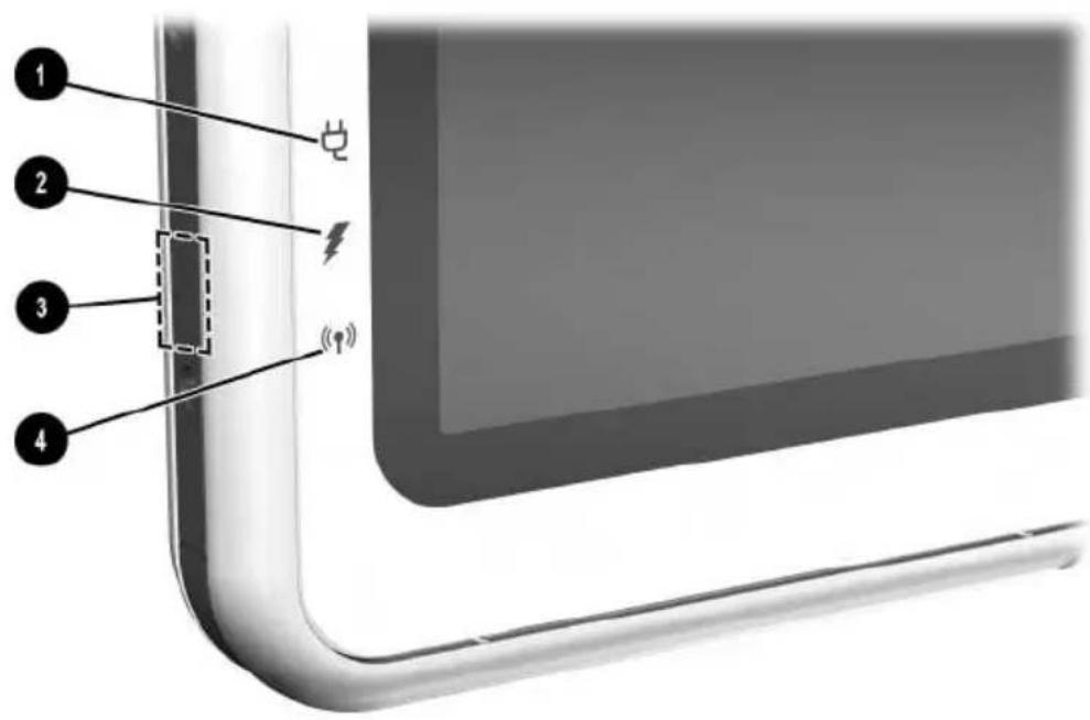
Component Description
① AC adapter light: On: AC power is being supplied through the AC adapter. ② Battery light: On: A battery pack is charging. Flashing: A battery pack that is the only available power source has reached a low-battery condition. ③ Bluetooth antenna: Sends and receives Bluetooth* Integrated Wireless signals.† ④ Wireless activity light: On: The wireless mini PCI and/or Bluetooth are on. Off: The wireless mini PCI and/or Bluetooth are off.
*Bluetooth is not available on all models.
For optimal performance when using Bluetooth, keep the area around the antenna free from obstructions.
Front: Pen-Activated Buttons

Component Description
1 Tablet PC Input Panel launch button* When Windows is running, opens the Microsoft Tablet PC Input Panel application, which includes a handwriting pad and an on-screen keyboard.
2 Journal launch button* When Windows is running, opens and closes the Microsoft Journal application, which supports handwriting.
3 Rotate button* Switches the image between landscape and portrait orientation.
*This table describes default settings. For information about changing the functions of the Tablet PC Input Panel launch, Journal launch, and rotate buttons, see Chapter 2, "Pen, Command Controls and Keyboards."
Right Side: Power Switch and Power/Standby Light

Component Description
1 Power switch* When the tablet PC is:
Off: Turns on the tablet PC. On: Initiates Standby.* In Standby: Resumes tablet PC from Standby. In Hibernation: Resumes tablet PC from Hibernation.* If the system has stopped responding and Windows shut down procedures cannot be used, slide and hold for 4 seconds to turn off the tablet PC.
2 Power/standby light On: Tablet PC is on.
Flashing: Tablet PC is in Standby. Off: Tablet PC is off or in Hibernation.
*This table describes default settings. For information about changing the functions of the power switch and about using Standby and Hibernation, refer on this CD to the Software Guide, "Power" chapter.
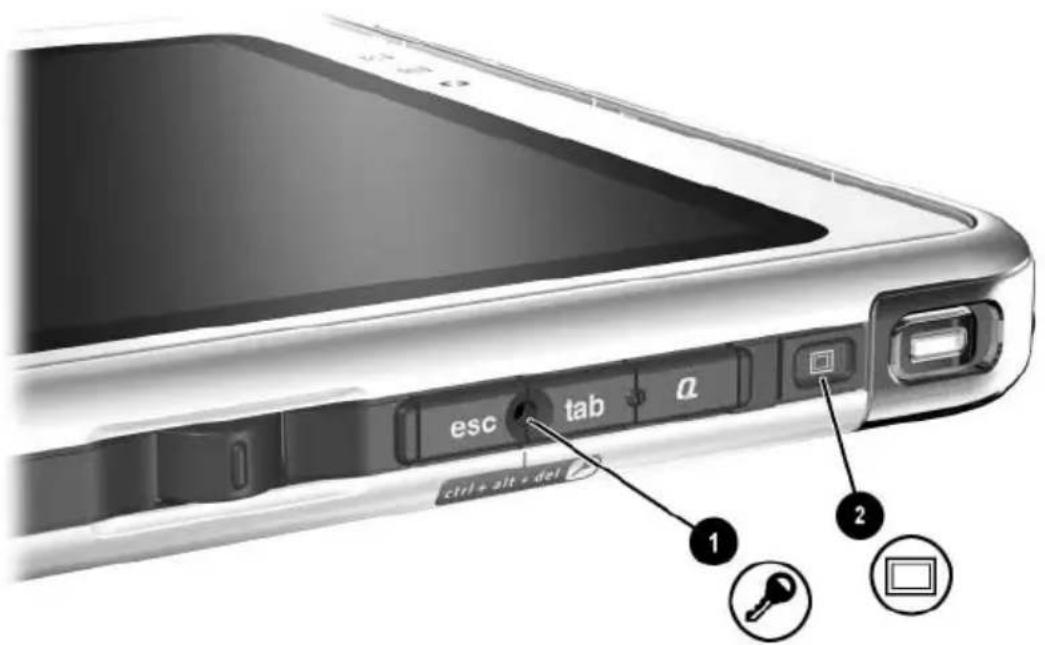
Right Side: Windows Security and Display Toggle Buttons
Component Description
① Windows Security button* When pressed with the pen tip or a small object like the end of a paper clip while: ■Windows is open, enters the ctrl+alt+delete command.† ■The Setup utility is open, enters the reset command.
② Display Toggle button
When Windows is running, toggles the external monitor display settings:
■Internal only ■Internal and External ■Extended Desktop
*This table describes default settings. For information about changing the functions of the Windows Security button, see Chapter 2, "Pen, Command Controls and Keyboards."
†To protect your work and the system, the ctrl+alt+delete command cannot be entered using the Ctrl, Alt, and Del keys on the on-screen keyboard.
Right Side: Esc, Tab and Q Menu Buttons

Component Description
① Esc button* While the tablet PC is:
■Starting up and a flashing pointer is displayed on the screen, opens the Setup utility.
In Windows, functions like esc on a standard keyboard.
② Tab button* When Windows is running, functions like tab on a standard keyboard.†
③ Q menu button* When Windows is running, opens or closes the Q Menu.
*This table describes default settings. For information about changing the functions of the esc, tab, and Q menu buttons, see Chapter 2, "Pen, Command Controls and Keyboards."
† The tab button can also be used, instead of an F12 command, to respond to a Network Service Boot prompt during startup.
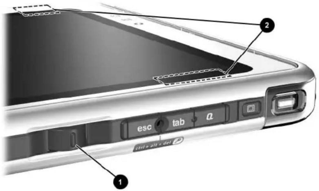
Right Side: Jog Dial and Antenna
Component Description
① Jog dial* Functions like enter and the up and down arrow keys on a standard keyboard.
■ Press inward to enter a command.
■ Rotate upward to scroll upward.
■ Rotate downward to scroll downward.
② Antennas, not visible from the outside of the tablet PC
② Antennas, not visible from the outside of the tablet PC
Sends and receives internal wireless LAN signals. †
*This table describes default settings. For information about changing the rotation functions of the jog dial, see Chapter 2, "Pen, Command Controls and Keyboards."
For optimal performance, keep the antennas free from obstructions while you are using an internal wireless LAN.
Component Description

Left Side: Attachment Slots and Keyboard Connector
| 1 | Docking alignment slots (2) Secure the tablet PC to an optional Tablet PC Docking Station. |
| 2 | Speakers (2) Produce stereo sound. |
| 3 | Audio-out jack Connects optional stereo headphones or powered stereo speakers. |
| 4 | Headset jack Connects an optional headset, such as a mobile telephone headset with a microphone and a monaural ear piece. |
| 5 | Microphone jack Connects an optional monaural or stereo microphone. |
| 6 | Microphone Inputs monaural sound.* |
| *If you are using speech recognition or other software that requires optimal sound quality, you must use an optional external microphone or a headset. | |
Left Side: Attachment Slots and Keyboard Connector

| Component Description | |
| 1 | Screen protector slots (2) Secure the screen protector* when it is attached to the tablet PC. |
| 2 | Universal attachment slots (2) Secure the portfolio, a screen protector*, or an attachment, such as a tablet PC keyboard, to the tablet PC. |
| 3 | Keyboard connector Connects the tablet PC keyboard to the tablet PC. |
| 4 | Alignment key slot Accepts an alignment key to safeguard attachment procedures. For example, matching the alignment key on the tablet PC keyboard to the alignment key slot helps you correctly orient the tablet PC to the keyboard as you attach the tablet PC to the keyboard. |
| *A screen protector is included with an optional Tablet PC Docking Station. | |
Left Side: Security Cable Slot, Vent and Antenna

Component Description
① IrDA Fast Infrared Port Transmits and receives infrared transmissions between the tablet PC and other infrared devices. ② Security cable slot Attaches an optional security cable to the tablet PC. ③ Vent Allows airflow to cool internal components.
To prevent overheating, do not obstruct the vent. Do not allow a hard surface, such as an adjoining optional printer, or fabric, such as bedding or clothing, to block airflow.
4 Antenna*, not visible from the outside of the tablet PC Receives internal wireless LAN signals.†
*The tablet PC has 2 antennas. The other antenna is found on the right side of the tablet PC.
† For optimal performance, keep the antennas free from obstructions while you are using an internal wireless LAN.
Top: Connectors and Jacks

Component Description
| 1 | USB connector Connects an optional USB 2.0- or 1.1-compliant device.* | |
| 2 | External MultiBay connector | Connects an optional USB 2.0- or 1.1-compliant device.* |
| 3 | RJ-11 telephone jack Connects a modem cable. | |
| 4 | RJ-45 network jack Connects an Ethernet network cable. | |
| 5 | External monitor connector | Connects an optional VGA external monitor or projector. |
| 6 | AC power connector Connects an AC adapter or an optional DC cable, Auto/Air Cable, or Automobile Power Adapter/Charger. | |
| *If an optional External MultiBay is connected to the USB connector, the External MultiBay must also be connected to external power. If an External MultiBay is connected to the External MultiBay connector, it is not necessary to connect the External MultiBay to external power. | ||
Top: Pen Holder and LAN Connection Lights
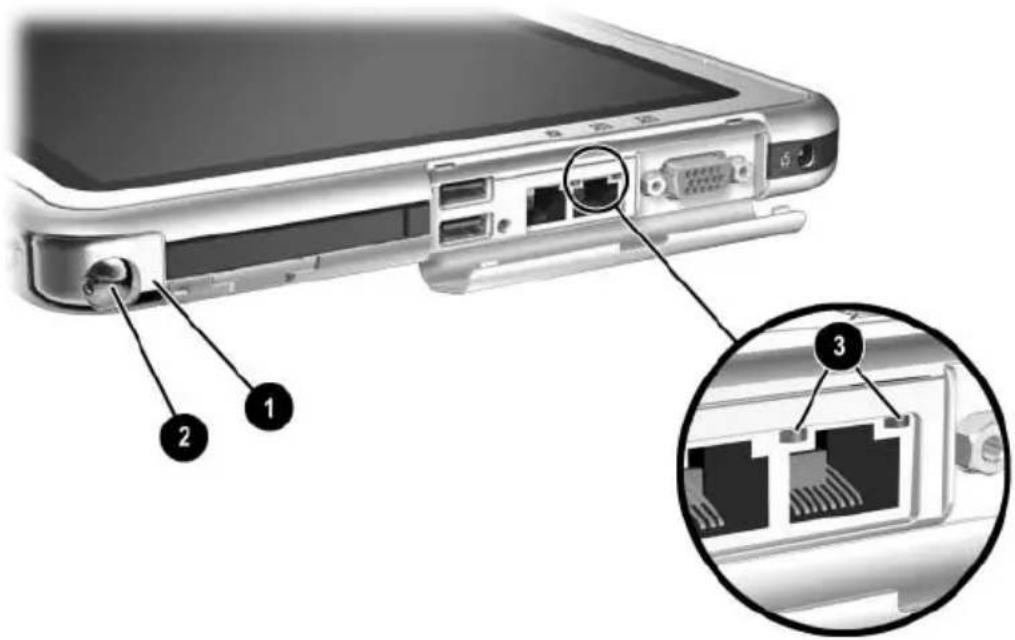
Component Description
| 1 | Pen holder (shown with pen 2 inserted) | Secures the pen to the tablet PC. |
| 3 | LAN connection lights (2) Both lights off: The tablet PC is not connected to a LAN.Both lights on: The tablet PC is connected to a LAN with a 100 Mbps link.Green light on and yellow light off: The tablet PC is connected to a LAN with a 10 Mbps link. | |
Top: Card Slots, Buttons and Tether Eyelet

Component Description
① PC Card slot Supports an optional Type I or Type II 32-bit (CardBus) or 16-bit PC Card.
② PC Card eject button Ejects an optional PC Card from the PC Card slot.
③ Tablet PC tether eyelet: Used with the tether eyelet on the pen, enables you to tether the pen to the tablet PC.
④ SD (Secure Digital) Card slot: Supports an optional SD Card.
Back: Attachment Features and Hard Drive Bay
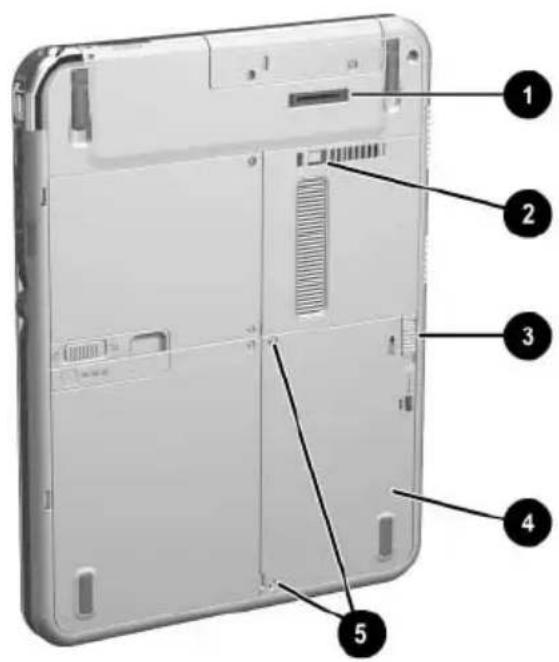
| Component Description | |
| 1 | Docking connector Connects the tablet PC to an optional Docking Station. |
| 2 | Docking restraint latch recess Accepts the docking restraint latch on an optional Docking Station to secure the tablet PC to the Docking Station. |
| 3 | Attachment release switch Releases an attachment, such as the portfolio, a screen protector*, or an optional tablet PC keyboard, from the universal attachment slots on the tablet PC. |
| 4 | Hard drive bay Holds the system hard drive. |
| 5 | Hard drive bay retaining screws (2) Secure the hard drive bay cover to the tablet PC. |
| *A screen protector is included with an optional Tablet PC Docking Station. | |
Back: Battery Bay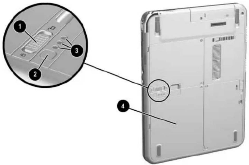
| Component Description | |
| 1 | Battery pack release latch Releases the battery pack from the battery bay. |
| 2 | Battery quick check button on battery pack* Activates the battery quick check lights (see below) which display how much charge remains in the battery pack. |
| 3 | Battery quick check lights (3) on battery pack* On: Each light represents a percent of a full charge. For example, when all 3 lights are on, the battery pack is fully charged.Flashing: When one light is flashing, less than 5 percent of a full charge remains in the battery pack. |
| 4 | Battery bay Holds the battery pack. Also, contains one battery pack security screw.* |
| *This illustration shows the battery pack inserted in the battery bay. The battery pack is included with the tablet PC, but is not inserted. For insertion instructions and information about using a battery pack security screw for protection against theft, see Chapter 3, “Battery Packs.” | |
Back: Memory and Mini PCI Compartment
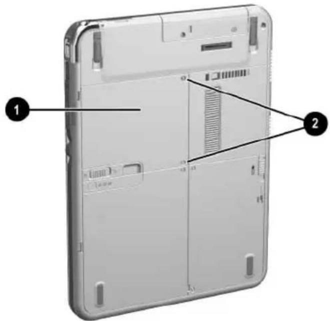
Component Description
① Memory and mini PCI (Peripheral Component Interconnect) compartment, not visible from the outside of the tablet PC.
Contains one memory slot for a PC133-compliant memory module. Also, holds an optional mini PCI board such as a wireless board. (A mini PCI board is included with some tablet PC models.)

The FCC does not allow unauthorized mini PCI devices to be used in the tablet PC. Installing an unsupported mini PCI device can prevent your tablet PC from operating properly and may result in a warning message. To resume proper operation, remove the unauthorized device. Contact your HP Customer Care Center if a warning message about your mini PCI device displays in error.
② Memory and mini PCI compartment retaining screws (2): Secure the memory and mini PCI compartment cover to the tablet PC.
Secure the memory and mini PCI compartment cover to the tablet PC.
Back: Tilt Feet and Pad Feet
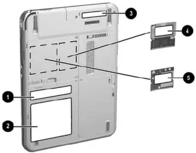
| Component Description | ||
| 1 | Microsoft Certificate of Authenticity label (inside the battery bay) | Contains the Product Key number. You may need this number to update or troubleshoot the operating system. |
| 2 | System label Provides regulatory information about the tablet PC. | |
| 3 | Product identification label Contains the serial number of the tablet PC and a code describing the original configuration of the tablet PC. You will need the serial number if you call HP Customer Care. | |
| 4 | Modem approvals label Lists the countries in which the modem has been approved for use.* | |
| 5 | Wireless certification label (on mini PCI wireless device) | Lists the countries in which the wireless device has been approved for use.* |
| *You may need this information when traveling. | ||
Component Description

① Tilt feet (2): While the tablet PC is being used in portrait orientation as a free-standing tablet, can elevate the top of the tablet PC to provide a comfortable writing and viewing angle.
① Tilt feet (2) While the tablet PC is being used in portrait orientation as a free-standing tablet, the tilt feet can elevate the top of the tablet PC to provide a comfortable writing and viewing angle.
② Pad feet (2) Stabilize the tablet PC when the tablet PC is placed as a free-standing tablet on a flat surface.
Additional Tablet PC Standard Components
The components included with the tablet PC vary by geographical region and the tablet PC hardware ordered. The following illustrations and tables identify the standard external components included with most tablet PC models.
These illustrations do not include supplementary documentation, supplementary CDs, the portfolio that shipped attached to the tablet PC or an optional keyboard, or optional devices such as PC Cards or drives. The system hard drive ships inside the hard drive bay.
Documentation CDs
Among the CDs included are:
■ Documentation Library CD, which includes product-specific documentation for the tablet PC, along with modem, networking, safety, and regulatory information. For information about using the Documentation Library CD, refer to the printed Startup Guide included with the tablet PC. ■ Documentation Library Wireless LAN CD, which includes documentation on the wireless devices available for the tablet PC. ■ Documentation Library Bluetooth CD, which includes the guides and software for Bluetooth wireless connection.

Wireless information may vary depending upon the exact configuration of your tablet PC.
Cords and Cables
Component Description
① Power cord* Connects the AC adapter to an AC electrical outlet. ② Modem cable Connects the modem to an RJ-11 telephone jack or to a country-specific modem adapter.

The modem cable has a 6-pin RJ-11 telephone connector at each end.
③ Network cable Connects the tablet PC to an RJ-45 (Ethernet network) jack. (A network cable is included with network models only.)

The network cable has an 8-pin RJ-45 network connector at each end.
*Power cords vary in appearance by region.
Adapters and Accessories

Component Description
| 1 | AC adapter* Converts AC power to DC power. | |
| 2 | Country-specific modem adapter (included by region as required with modem models only) | Adapts the modem cable to a non-RJ-11 telephone jack. |
| 3 | Japan-specific outlet adapter (Japan only) | Connects the AC adapter to a 2-prong electrical outlet. |
| 4 | Battery pack Runs the tablet PC when the tablet PC is not connected to external power. | |
| *AC adapters vary in appearance by region. The only AC adapter that should be used with the tablet PC is the AC adapter included with the tablet PC or a replacement AC adapter provided by HP. | ||
Tablet PC Keyboard Components
This section identifies the hardware components of an optional tablet PC keyboard.
For information about detaching, attaching, and adjusting the keyboard, see Chapter 8, “External Device Connections.”
For information about using the keyboard, see Chapter 2, "Pen, Command Controls and Keyboards."
Front: Lights and Pointing Device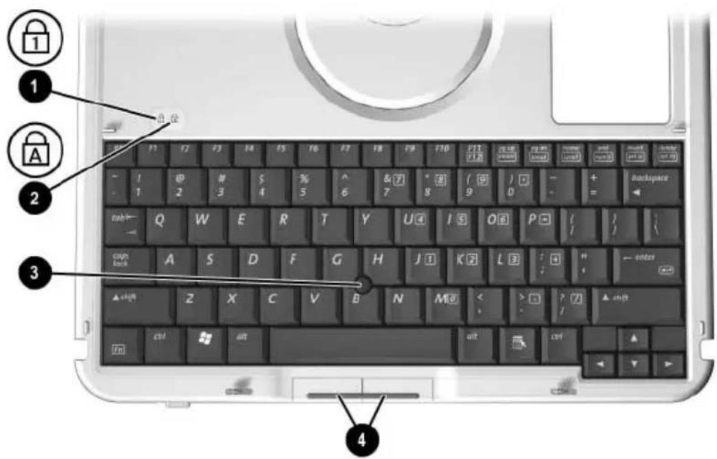
| Component Description | |
| 1 | Num lock light On: The keypad is on. |
| 2 | Caps lock light On: Caps lock is on. |
| 3 | Pointing stick Moves the pointer and selects and activates items on the screen. |
| 4 | Left and right pointing stick buttons Function like the left and right buttons on an external mouse. |
Front: Keys
Component Description
① Function keys (11) Perform system and application tasks. For example, in Windows and many applications, pressing F1 opens a Help file. To enter an F11 function, press F11/F12. To enter an F12 function, press Fn+F11/F12.
② Fn Combines with other keys to perform system tasks. For example, pressing Fn+num lk turns on the keypad.
③ Keypad keys (15)* Can be used like the keys on an external numeric keypad.
④ Microsoft logo key Displays the Windows Start menu.
⑤ Applications key Displays a shortcut menu for an item beneath the pointer.
*For more information about using keypad keys, see Chapter 2, "Pen, Command Controls and Keyboards."
Front: Positioning and Security Features
Component Description
| 1 | Rotation disk Rotates the tablet PC while it is attached to the keyboard. | |
| 2 | Docking alignment notches (4) | Help guide the tablet PC and keyboard into an optional Docking Station. |
| 3 | Keyboard latch When the tablet PC and keyboard are closed, locks the tablet PC to the keyboard: ■Slide to the right to lock the tablet PC to the keyboard. ■Slide to the left to unlock the tablet PC from the keyboard. | |
Top

Component Description
1 Alignment key: Inserts into the alignment key slot on the tablet PC to safeguard attachment procedures. For example, matching the alignment key to the alignment key slot on the tablet PC helps you correctly orient the tablet PC to the keyboard as you attach the tablet PC to the keyboard.
2 Keyboard hooks (2): Secure the tablet PC to the keyboard.
3 Keyboard connector: Connects the tablet PC to the keyboard.
4 Tilt adjustment: Tilts the tablet PC upward or downward while it is connected to the keyboard.
Back

| Component Description | |
| 1 | Screen protector slots (2) Secure a screen protector* to the keyboard. |
| 2 | Attachment release switch Releases attachments, such as the portfolio, a screen protector*, or the tablet PC, from the keyboard. |
| 3 | Docking connector pass-through Allows the tablet PC to be connected to an optional Docking Station while the tablet PC is attached to the keyboard. |
| 4 | Universal attachment slots (2) Secure the portfolio, a screen protector*, or the tablet PC to the keyboard. |
| *A screen protector is included with an optional Tablet PC Docking Station. | |
Additional Keyboard Standard Component
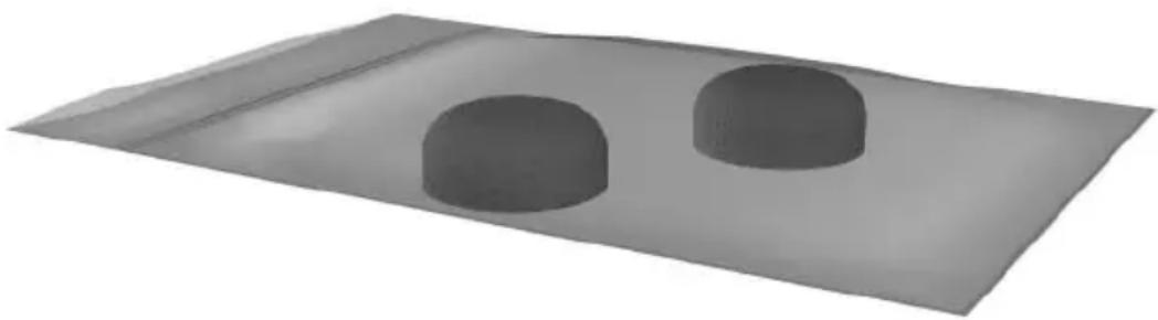
Component Description
Spare pointing stick caps (2): Replace a worn pointing stick cap.
Pen, Command Controls and Keyboards
You can enter and access information on the tablet PC by voice (supported in English only), pen, command controls, the on-screen keyboard, or the tablet PC keyboard or external USB keyboard. An optional external mouse can be connected to a USB connector on the tablet PC, an optional Docking Station, or some external USB keyboards.
This chapter provides information about using the pen, command controls, the on-screen keyboard, and a tablet PC keyboard.
Pen
You can write with the pen in pen-specific applications such as Journal and Tablet PC Input Panel, in all Microsoft Office applications, and in most other Windows applications and utilities. The information you write on the screen with the pen can be filed, searched, and shared among most Windows applications.
To access basic information about using the pen within the operating system, refer to the printed Windows XP Tablet PC Edition Start Here guide included with the tablet PC.
To access on-screen tutorials which include more detailed information about using the pen in the tablet PC system:
- Open Windows Explorer. To open Windows Explorer from the Start button, select Start > All Programs > Accessories > Windows Explorer.
- In Windows Explorer, select My Computer > Local Disk (C:) > WINDOWS > Help > latute.hta.
Entering Information with the Pen
Identifying the Pen Tip and Pen Button
The pen interacts with the tablet PC whenever the tip of the pen ① is within 1.27 cm (0.5 inch) from the screen. The pen button ② emulates the functions of the right-click button on an external mouse.

Identifying the pen tip and pen button
Holding the Pen
Hold the pen as if you were writing with a standard pen or pencil. Position your hand on the pen so that you will not accidentally press the pen button.
As you monitor the movements of the pen, focus on the pointer, not on the tip of the pen.
Performing Mouse Clicks with the Pen
To select an item on the screen as you would with the left button of an external mouse:
Tap the item with the tip of the pen.
To double-click an item on the screen as you would with the left button of an external mouse:
Tap the item twice with the tip of the pen.
To select an item as you would with the right button of an external mouse:
Press and hold down the pen button, then tap the item with the tip of the pen.
Performing Other Procedures with the Pen
In addition to emulating mouse clicks, the pen can be used for the following tasks:
To display the pointer location, hold the pen tip immediately over any location on the tablet PC screen without touching the screen with the pen tip.
To display the menu options related to an item on the screen, tap the screen with the pen tip.
To write with the pen, write on the screen with the tip of the pen.
To press a pen-activated button, tap the button with the tip of the pen.
Pressure-Sensitivity
The tablet PC pen is equipped with a pressure-sensitive feature. This means that you can manipulate the pen to create lines of various thickness, depending upon the amount of pressure you use to write.
Calibrating the Pen
The pen can function at the default calibration or at a calibration set by another user. However, HP highly recommends that you use the pen only while it is calibrated to your personal handwriting and mouse action motions. Calibration optimizes pen performance for all users and particularly for left-handed users.
To calibrate the pen:
- Select Start > Control Panel > Printers and Other Hardware icon > Tablet and Pen Settings window > Settings tab.
- Select the Calibrate button.
- Follow the instructions on the screen.
Tap the pen in the exact center of each of the calibration markers. The calibration markers are displayed on the screen as plus signs (+).
Be sure to calibrate the pen for use in both portrait and landscape orientations.

You can display information about any setting in the Tablet and Pen Settings window by selecting the question mark button in the upper right corner of the window, then selecting a setting. A definition, explanation, or procedure is displayed.
Using the Pen Holder
To protect the pen when you are not using it, insert the pen, tip first, into the pen holder on the tablet PC.
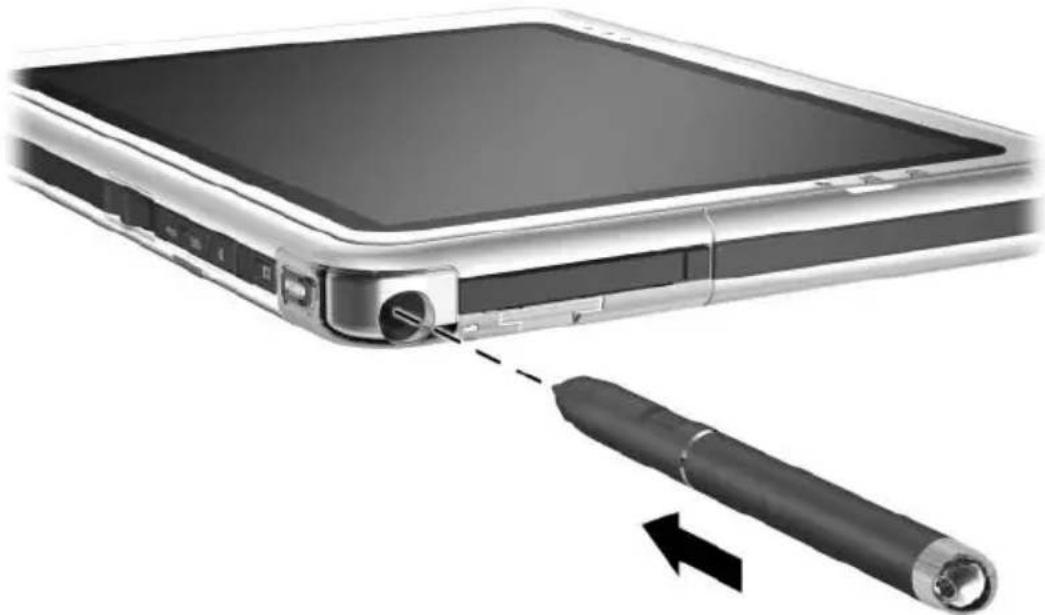
Inserting the pen into the pen holder
Setting Pen Preferences
Pen preferences are set in the Tablet and Pen Settings window of the operating system. The preferences include settings that optimize handwriting recognition and the location of on-screen menus for either right-handed or left-handed users. To access the pen settings:
Select Start > Control Panel > Printers and Other Hardware icon > Tablet and Pen Settings window > Pen Options tab.
The preferences you set in the Tablet and Pen Settings window are specific to the pen and the tablet PC.
Pointing device preferences, such as pointer speed, click speed, and mouse trails, that apply to any pointing device in the system, are set in the Mouse Properties window. For instructions, see “Setting Pointing Device Preferences” in the “Tablet PC Keyboard” section later in this chapter.
Command Controls
The 9 command controls enable you to enter commands usually entered with keyboard keys while you are using the tablet PC without an external keyboard. The command controls can also be used while you are using the on-screen keyboard or an optional keyboard.
Identifying Command Controls
① Tablet PC Input Panel launch button ② Journal launch button ③ Rotate button ⑥ Tab button
④ Display Toggle button
⑤ Q menu button
⑦ Windows Security button
⑧ Esc button
⑨ Jog dial

Identifying the command controls
Command Controls Quick Reference
The following table identifies the default setting and activation procedure for each command control.
■To activate a pen-activated button, tap the button with the tip of the pen. ■To activate a manually activated button, press and release the button.
| Button Default Function Activation | ||
| Tablet PCInput Panel launch button* | Opens and closes the Tablet PC Input Panel application, which includes a writing pad and the on-screen keyboard. | Pen |
| Journal launch button* | Opens and closes the Journal application. | Pen |
| Rotate button* | Switches the image between landscape and portrait orientation. | Pen |
| Display Toggle button | When Windows is running, toggles the external monitor display settings:■Internal only■Internal and External■Extended Desktop | Manual |
| Q menu button* | Opens and closes the Q Menu. Manual | |
| Tab button* Functions like tab on a standard keyboard. | Manual | |
(Continued)
| Button Default Function Activation | ||
| Windows Security button* | In Windows, functions like the ctrl+alt+delete command on a standard keyboard.In the Setup utility, functions like the reset button on some computers. | Manual |
| Esc button* During startup, opens the Setup utility.In Windows, functions like esc on a standard keyboard. | Manual | |
| Jog dial* Enters commands or scrolls the image upward or downward. | Manual | |
| *These controls are programmable. For instructions, see “Setting Command Control Preferences,” later in this chapter. | ||
Using Command Controls
Tablet PC Input Panel Launch Button
Tap the Tablet PC Input Panel launch button with the pen tip when the tablet PC is in Windows to open the Tablet PC Input Panel application. The Tablet PC Input Panel application displays a keyboard on the screen and can also display a writing pad, which supports handwriting.
To protect your work and the system, the ctrl+alt+delete command cannot be entered using the Ctrl, Alt, and Del keys on the on-screen keyboard. To enter the ctrl+alt+delete command, press the Windows Security button on the tablet PC with the pen tip or a small object like the end of a paper clip.
For more information about using the Tablet PC Input Panel application, refer to the Help file within the application, the “On-Screen Keyboard” section, later in this chapter, or to an on-screen tutorial. To access the tutorials:
- Open Windows Explorer. To open Windows Explorer from the Start button, select Start > All Programs > Accessories > Windows Explorer.
- In Windows Explorer, select My Computer > Local Disk (C:) WINDOWS > Help > latute.hta.
Journal Launch Button
Tap the Journal launch button with the pen tip to open the Journal application. The Journal application is a handwriting program unrelated to the Journal feature in Microsoft Outlook.
For more information about using the Journal application, refer to the Help file within the application or to an on-screen tutorial. To access the tutorials:
- Open Windows Explorer. To open Windows Explorer from the Start button, select Start > All Programs > Accessories > Windows Explorer.
- In Windows Explorer, select My Computer > Local Disk (C:) WINDOWS > Help > latute.hta.
Rotate Button
Tap the rotate button with the pen tip when the tablet PC is in Windows to rotate the image on the screen 90 degrees. For example, if the image is in landscape orientation, tap the rotate button to rotate the image to portrait orientation.
Display Toggle Button
Press the Display Toggle button to adjust the display settings for the tablet PC and the optional external monitor.
When Windows is running, the Display Toggle button toggles the external monitor display settings in the following order:
■Internal only ■Internal and External ■Extended Desktop
Q Menu Button
Press the Q menu button manually when Windows is running to open or close the Q Menu. The Q Menu provides quick access to programmable tasks and destinations including:
■System controls, such as volume and screen brightness. ■Key simulations such as Capture Screen, which functions like the print screen key on a standard keyboard. ■Applications, files, or folders on a drive, a network, or the Internet.
To select an item from the Q Menu without using the pen or a keyboard, press the Q menu button to display the Q Menu, rotate the jog dial upward or downward until your selection is highlighted, then press the jog dial inward.
For more information about using the Q Menu, refer on this CD to the Software Guide, “Q Menu and Desktop Video Profiles” chapter.
Tab Button
Press the tab button manually to enter the tab command as you would by pressing the tab key on a standard keyboard. The tab button can be used with or without the on-screen keyboard or an optional keyboard.
The function of the tab command varies by application. For example, in Microsoft Word the tab command indents and in Microsoft Excel the tab command moves the pointer to an adjoining cell.
The tab button can be combined with keystrokes on the on-screen keyboard or an external keyboard. For example, press the alt key on either keyboard, then the tab button, to display and select from among all open applications.
Windows Security Button
Press the Windows Security button with the pen tip or a small object like the end of a paper clip to enter the Ctrl+Alt+Delete command while you are in Windows or the reset command while you are in the Setup utility. The Ctrl+Alt+Delete command cannot be entered using the Ctrl, Alt, and Del keys on the on-screen keyboard.
Ctrl+Alt+Delete Command
When the tablet PC is in Windows, the Windows Security button clears your work from the screen and displays the Windows Security window in which you can lock, log off, or shut down the tablet PC, initiate Standby or Hibernation, or open Task Manager.
The Shut Down option in the Ctrl+Alt+Delete window enables you to safely shut down the tablet PC if the system has become unresponsive.
Task Manager displays the status of all open applications and enables you to close an application that has become unresponsive.
If the system remains unresponsive after selecting Shut Down in the Windows Security window, slide and hold the power switch for 4 seconds. For additional shut down procedures, refer on this CD to the Software Guide, “Power” chapter. For information about using the Ctrl+Alt+Delete command in non-Windows applications, refer to the application documentation.
Reset Command
When the Setup utility is open, the Windows Security button simulates the reset button found on some computers. When the tablet PC is reset, the tablet PC restarts and all unsaved information is lost.
The reset function can be used to restore functionality when the system has become unresponsive. For information about the Setup utility, which is a non-Windows utility, refer on this CD to the Software Guide, “Setup and Support Utilities” chapter.
Esc Button
Press the esc button manually to open the Setup utility or to use the esc button like the esc key on a standard keyboard.
Setup Utility Function
While the tablet PC is starting up, the HP logo is displayed and the cursor flashes in the upper right hand corner of the screen. During this time, press the esc button to open the Setup utility. For information about the Setup utility, refer on this CD to the Software Guide, “Setup and Support Utilities” chapter.
Esc Key Function
When the tablet PC is on, press the esc button to enter the esc command as you would by pressing the esc key on a standard keyboard. The esc button can be used with or without the on-screen keyboard or an external keyboard.
The function of the esc command varies among applications. Esc is usually used to exit a mode or routine or to cancel a function.
The esc button can be combined with keystrokes on the on-screen keyboard or an external keyboard. For example, press the ctrl key on either keyboard, then the esc button, to display the Windows Start menu.
Jog Dial
Press or rotate the jog dial manually to enter commands or scroll vertically:
Press inward to simulate the function of the enter key on a standard keyboard. Rotate upward or downward to scroll toward the top or bottom of an image.
At the default setting, the jog dial scrolls line by line like the up and down arrow keys on a standard keyboard. The jog dial can be set to scroll page by page like the page up and page down keys on a standard keyboard or three lines at a time like a mouse wheel. Other settings, in addition to scroll functions, are also available. For instructions, see "Setting Command Control Preferences," next in this chapter.
Setting Command Control Preferences
All command controls except the Display Toggle button and the enter function of the jog dial can be customized to launch applications, simulate key combinations, or perform preset system functions.
Each programmable command control can be assigned to 4 settings. Each setting applies only to 1 of 4 views:
Portrait-Primary, Portrait-Secondary, Landscape-Primary, Landscape-Secondary
Command control preferences are set in the Tablet and Pen Settings window. You must select a view before setting a preference. Each view is illustrated in the Button Location pane of the Tablet and Pen Settings window as you select it.
If you are unfamiliar with the four views, you may want to read "Selecting a View" next in this section, before setting a command control preference.
Selecting a View
In the Portrait-Primary and Portrait-Secondary views, the image is displayed vertically, in portrait orientation. In the Landscape-Primary and Landscape-Secondary views, the image is displayed horizontally, in landscape orientation.
A portrait view is often optimal when you are using the tablet PC as a handheld. A landscape view is often optimal when you are displaying the image on an optional external monitor or projector.
In the primary views (Portrait-Primary and Landscape-Primary), the image switches clockwise between vertical and horizontal. In the secondary views (Portrait-Secondary and Landscape-Secondary), the image switches counterclockwise between vertical and horizontal.
Left-handed users may find the secondary views more convenient.
HP recommends that you not use a secondary view while using the internal wireless. The positions commonly occupied by the tablet PC, external devices, and users while the tablet PC is in a secondary view may obstruct the antennas.
When you are facing the tablet PC screen with the tablet PC in portrait orientation, the antennas, not visible from the outside of the tablet PC, are on the right and left sides of the tablet PC, near the upper corners.
To switch the system among the Portrait-Primary, Landscape-Primary, Portrait-Secondary, and Landscape-Secondary views:
- Press the Q menu button.
- Select a view from the Q Menu. (The system switches to the view you select.)
For more information about using the Q Menu, including instructions for adding or removing items from the Q Menu, refer on this CD to the Software Guide, “Q Menu and Desktop Video Profiles” chapter.
Assigning or Changing a Preference
To assign or change the function of a programmable command control:
- Select Start > Control Panel > Printers and Other Hardware icon > Tablet and Pen Settings window > Tablet Buttons tab.
- In the Button Settings For field, select the view in which you want to use your preference. (The view is illustrated in the Button Location panel.)
- In the Tablet Button drop-down list, select the button you plan to assign.
To assign or change the function of rotating the jog dial upward, select Up. To assign or change the function of rotating the jog dial downward, select Down.
- Select the Change button. (The Button Action dialog box opens.)
- Select your preference in the Button Action dialog box. To save your preference, select the OK or Apply button.
Returning All Command Controls to Default Settings
To return the settings on all command controls to their default settings:
- Select Start > Control Panel > Printers and Other Hardware icon > Tablet and Pen Settings window > Tablet Buttons tab.
- In the Button Settings For field, select the view in which you want to change all command controls to their default settings.
- Select the Reset button. (All command controls are returned to their default settings only in the orientation currently selected.)
- Select the Apply button, then select OK.
On-Screen Keyboard
The Tablet PC Input Panel application displays a keyboard on the screen. This on-screen keyboard simulates the functions of an optional keyboard.
To open the Tablet PC Input Panel application, tap the Tablet PC Input Panel launch button ① with the pen.
To type, tap a key. To switch the keys displayed in the top row between number keys and function keys, tap Func. To enter the ctrl+alt+delete command, press the Windows Security button ② on the tablet PC with the pen tip or a small object like the end of a paper clip. To protect your work and the system, the ctrl+alt+delete command cannot be entered using the Ctrl, Alt, and Del keys on the on-screen keyboard.
For more information about using the Tablet PC Input Panel application, see “Tablet PC Input Panel Launch Button” in the “Using Command Controls” section, earlier in this chapter.

Identifying the Tablet PC Input Panel launch and Windows Security buttons
Tablet PC Keyboard
An optional tablet PC keyboard that is thinner than the tablet PC but the same length and width is available from your HP authorized dealer, reseller, or service provider.
When the tablet PC is attached to the keyboard, the tablet PC can be folded down flush with the keyboard for transport or tilted upward and used like a notebook display.
This chapter provides information about using the keyboard pointing device and keypad.
For information about identifying other keyboard components, see Chapter 1, "External Components."
For information about attaching, detaching, and positioning the keyboard, see Chapter 8, "External Device Connections."
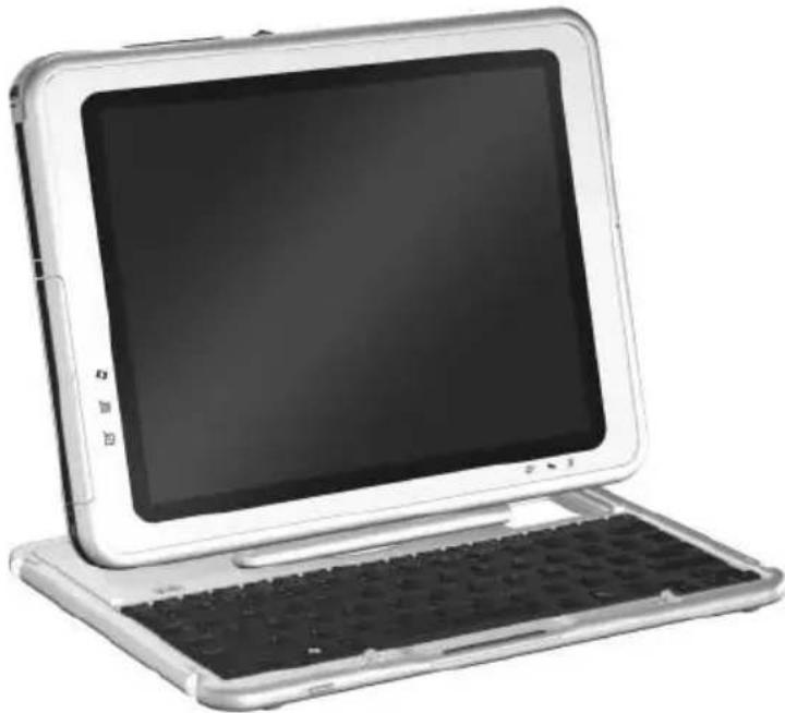
Using the tablet PC and tablet PC keyboard like a notebook
Using the Pointing Device
Navigating and Selecting
To move the pointer, press the pointing stick ① in the direction you want to move the pointer. To increase or decrease pointer speed, increase or decrease the directional (not downward) pressure on the pointing stick. If the pointer continues to move after you release the pointing stick, wait a few seconds and the pointer will stop moving.
Use the left ② and right ③ pointing stick buttons as you would the left and right buttons on an external mouse.
For information about replacing the pointing stick cap with one of the two spare pointing stick caps included with the keyboard, see Chapter 10, "Maintenance, Shipping and Travel."

Identifying pointing device components
Setting Pointing Device Preferences
Pointer speed, click speed, mouse trails, and other pointing device preferences can be set in the Mouse Properties window of the operating system. To access Mouse Properties, select Start > Control Panel > Printers and Other Hardware icon > Mouse icon.
To learn more about a setting, select the question mark icon in the upper right corner of the window, then select the setting. To select a setting, follow the instructions on the screen, then select the OK button.
Mouse Properties settings apply to any pointing device in the system, including the pen, an optional mouse, and the pointing device on an optional tablet PC keyboard.
Using the Keypad
The tablet PC keyboard includes 15 keys that can be used like the keys on an external numeric keypad. When the keypad is turned on, each of these 15 keys performs the functions indicated by the icon in the upper right corner of the key. The standard functions of the keypad keys can still be accessed while the keypad is turned on.
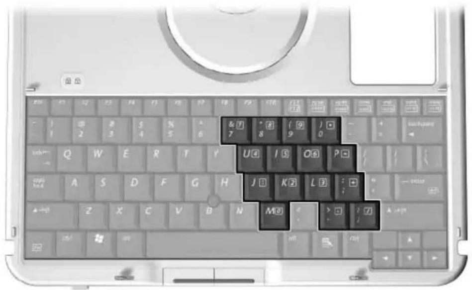
Identifying the keypad keys
Turning the Keypad On and Off
Press Fn+num lk ① on the keyboard to turn the keypad on and off.
■ When the keypad is on, press Fn+num lk ① to turn the keypad off. The num lock light ② turns off. ■ When the keypad is off, press Fn+num lk ① to turn the keypad on. The num lock light ② turns on.

Identifying the Fn and num lk keys and the num lock light
Switching Keypad Keys Between Standard and Keypad Functions
You can temporarily switch the functions of keypad keys between their standard keyboard functions and their keypad functions by using Fn ① and shift ②.
■To use a key on the keypad temporarily as a keypad key while the keypad is off, press and hold Fn as you press the key.
■To use a keypad key temporarily as a standard key while the keypad is on:
☐ Press and hold Fn to type in lowercase.
Press and hold Fn+Shift to type in uppercase.
When Fn is released, the keypad keys return to their standard functions if the keypad is off or to their keypad functions if the keypad is on.

Identifying the Fn and Shift keys
Using F11/F12
F11/F12 provides both F11 and F12 functions.
To enter an F11 function, press F11/F12 ①. To enter an F12 function, press Fn+F11/F12 ②.

Identifying the F11/F12 and Fn keys
Running the Tablet PC on Battery Power
When the tablet PC is connected to external power, the tablet PC runs on external power.
When a charged battery pack is in the tablet PC and the tablet PC is not connected to external power, the tablet PC runs on battery power.
The tablet PC switches between external power and battery power according to the availability of an external power source. For example, if the tablet PC contains a charged battery pack and is running on external power supplied through the AC adapter, the tablet PC will switch to battery power if the AC adapter is disconnected from the tablet PC.
Whether to leave a battery pack in the tablet PC or in storage depends on how you work. Keeping a battery pack in the tablet PC enables the battery pack to charge whenever the tablet PC is connected to external power and also protects your work in case of a power outage.
On the other hand, a battery pack in the tablet PC slowly discharges even while the tablet PC is turned off.
If you will not be using the tablet PC for one month or more, removing the battery pack and storing it as described in “Storing a Battery Pack,” later in this chapter, will prolong its life. For more information about leaving your work, refer to the Software Guide, “Power” chapter on this CD.
Replacing a Battery Pack
Removing a Battery Pack

CAUTION: To prevent loss of work when removing a battery pack that is running the tablet PC, initiate Hibernation or turn off the tablet PC before removing the battery pack.
If you remove a battery pack that is running the tablet PC while the tablet PC is in Standby, your work is saved in Standby for up to one minute, then the tablet PC shuts down and your unsaved work is lost. If you remove a battery pack that is running the tablet PC while the tablet PC is on, the tablet PC shuts down immediately and your unsaved work is lost.
To remove a battery pack from the tablet PC:
- Turn the tablet PC front side down. (If a battery pack security screw is in place, remove the screw.)
- To unlock the battery pack release latch, slide the latch firmly toward the unlock icon ①. Then hold the latch as you disengage the 2 tabs on the battery pack from the 2 slots on the battery bay ② and lift the battery pack out of the battery bay ③.
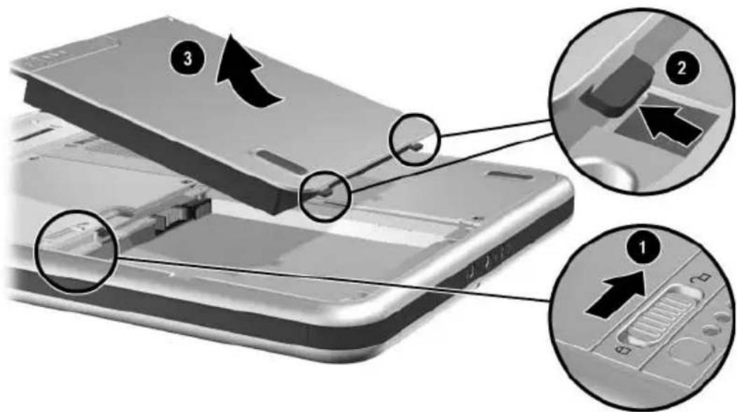
Removing a battery pack
Inserting a Battery Pack
To insert a battery pack into the tablet PC:
- Turn the tablet PC front side down.
- Align the 2 rectangular tabs ① on the battery pack with the 2 rectangular alignment slots ② in the battery bay.

Aligning the battery pack tabs with the battery bay alignment slots
- Angle the battery pack toward the alignment slots ① until the 2 tabs are inserted into the 2 alignment slots ②.
- Tilt the battery pack downward until it snaps into place ③.
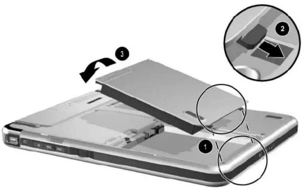
Inserting a battery pack
- If you initiated Standby or Hibernation before replacing the battery pack, slide and release the power switch to resume from Standby or Hibernation.
Securing a Battery Pack
Use the battery pack security screw to hold the battery pack in place, and to provide antitheft protection for the battery pack.
Accessing the Battery Pack Security Screw
A battery pack security screw ships inside the battery bay.
To access the battery pack security screw:
- Remove the battery pack as instructed in “Removing a Battery Pack” earlier in this section.
- Remove the battery pack security screw.
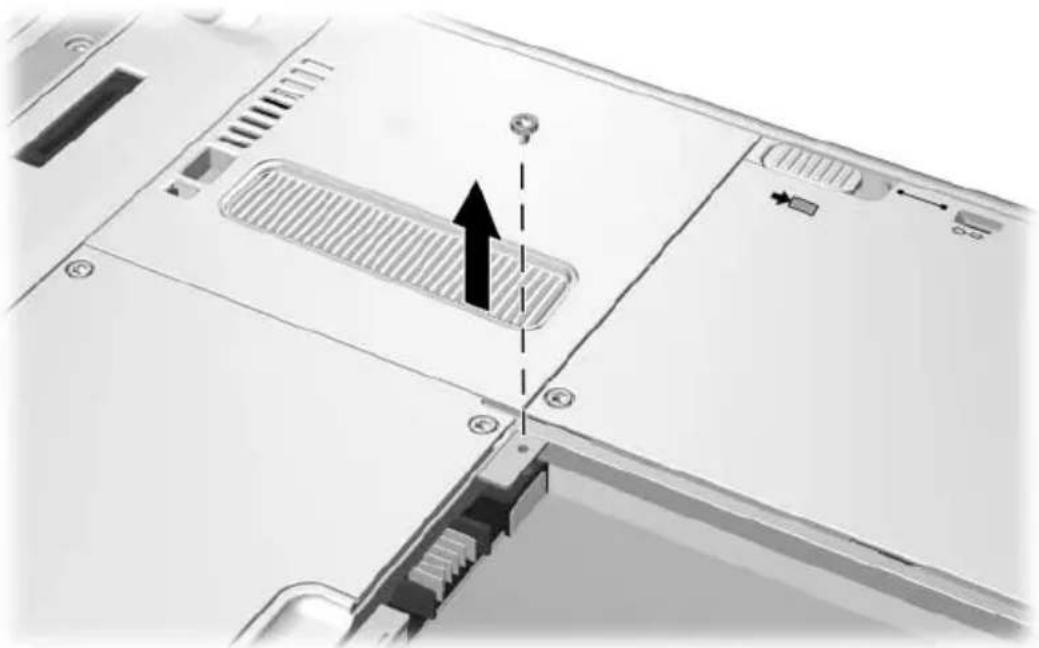
Removing the battery pack security screw
Inserting a Battery Pack Security Screw
To secure the battery pack in the battery bay with a battery pack security screw:
- Insert the battery pack into the battery bay as instructed in "Inserting a Battery Pack" earlier in this section.
- Insert a battery pack security screw through the battery pack case and into the tablet PC.

Inserting a battery pack security screw
Charging a Battery Pack
The battery pack in the tablet PC charges whenever the tablet PC is connected to external power.
The battery pack charges whether or not the tablet PC is in use, but charges faster when the tablet PC is off.
Charging may be delayed if a battery pack is new, has not been used for 2 weeks or more, or is much warmer or cooler than room temperature. Charging times vary.
The battery light displays charge status:
■On: the battery pack is charging. ■Off: the battery pack is fully charged. ■Flashing: the battery pack has 5 percent or less of a full charge.

Identifying the battery light
Charging a New Battery Pack
Fully charge the battery pack while the tablet PC is connected to external power through the AC adapter.
A new battery pack that has been partially charged, but not fully charged, can run the tablet PC, but battery charge displays may be inaccurate.
Charging an In-Use Battery Pack
To prolong battery life and increase the accuracy of battery charge displays:
Allow the battery pack to discharge to less than 10 percent of a full charge through normal use before charging it.
When you charge the battery pack, charge it fully. An in-use battery pack can be charged while the tablet PC is connected to external power through the AC adapter or an optional Automobile Power Adapter Charger, Docking Station, or DC cable.
An optional Auto/Air Cable can be used to run the tablet PC, but cannot be used to charge a battery pack.
Monitoring the Charge in a Battery Pack
Obtaining Accurate Charge Information
To increase the accuracy of all battery charge displays:
Allow a battery pack to discharge to less than 10 percent of a full charge through normal use before charging it. When you charge a battery pack, charge it fully. If a battery pack has not been used for one month or more, calibrate the battery pack instead of simply charging it. For calibration instructions, see "Calibrating a Battery Pack" later in this chapter.
Displaying Charge Information on the Screen
Accessing Charge Displays
To display battery charge information on the screen, use the operating system Power Meter feature.
To access Power Meter displays, use either of the following methods:
Select Start > Control Panel > Performance and Maintenance icon > Power Options icon > Power Meter tab. Select the Power Meter icon in the system tray.
To display the Power Meter icon in the system tray:
- Select Start > Control Panel > Performance and Maintenance icon > Power Options icon > Advanced tab.
- Select the Always Show Icon On The Taskbar check box.
- Select the OK button.
- If the icon is not displayed, select in the system tray the icon for Show Hidden Icons.
Interpreting Charge Displays
Power Meter displays battery charge status in both percent and time:
The percent indicates the amount of charge remaining in the battery pack.
The time indicates the approximate running time remaining on the battery pack if the battery pack continues to provide power at the current level. For example, the time remaining will decrease if you start backing up to an SD Card and will increase when the backup is complete.
A lightening bolt icon indicates that the battery pack is charging.
Displaying Charge Information on a Battery Pack
Charge information about a battery pack can be displayed on the battery pack with the Quick Check feature, which can be used whether or not the battery pack is inserted in the battery bay.
To display the percent of a full charge remaining in a battery pack, press the battery quick check button ① on the battery pack. The three battery quick check lights ② on the battery pack indicate the charge remaining in the battery pack.
Indication Percent of a Full Charge Remaining
| 3 lights on 67 to 100% |
| 2 lights on 34 to 66% |
| 1 light on 6 to 33% |
| 1 light flashing* 0 to 5% |
| *When the battery pack reaches 5% of a full charge, the battery light on the tablet PC also flashes. |

Identifying the quick check button and lights on a battery pack inserted in the battery bay
Managing Low-Battery Conditions
The information in this section describes default alerts and system responses.
Some low-battery condition alerts and system responses can be changed in the Power Options Properties window of the operating system. Preferences set in the Power Options Properties window do not affect lights.
For information about setting preferences in the Power Options Properties window, refer on this CD to the Software Guide, "Power" chapter, "Setting Power Preferences" section.
Identifying Low-Battery Conditions
Low-Battery Condition
When a battery pack that is the sole power source available to the tablet PC reaches a low-battery condition (5 percent of a full charge), the battery light flashes.
Critical Low-Battery Condition
If a low-battery condition is not resolved, the tablet PC enters a critical low-battery condition (1 percent of a full charge).
In a critical low-battery condition:
■ If Hibernation is enabled and the tablet PC is on or in Standby, the tablet PC initiates Hibernation. ■ If Hibernation is disabled and the tablet PC is on or in Standby, the tablet PC remains briefly in Standby, then shuts down and loses your unsaved work.
Hibernation is enabled by default. To verify that Hibernation is enabled, select Start > Control Panel > Performance and Maintenance icon > Power Options icon > Hibernate tab. If Hibernation is enabled, the Enable Hibernation check box is selected.
Resolving Low-Battery Conditions

CAUTION: If the tablet PC has reached a critical low-battery condition (one percent of a full charge) and has initiated Hibernation, do not slide the power switch until Hibernation is complete. Hibernation is complete when the power/standby light turns off.
When a Charged Battery Pack Is Available
To resolve a low-battery condition, select one of the following options:
Turn off the tablet PC or initiate Hibernation, insert a charged battery pack while the tablet PC is off or in Hibernation, then turn on the tablet PC.
To replace the battery with minimal disruption to your work, slide and release the power switch to initiate Standby, confirm that Standby has been initiated by making sure the power/standby light is flashing, then replace the battery pack within one minute.

CAUTION: To prevent loss of work, be sure to replace the battery pack within one minute. The bridge battery runs the tablet PC in Standby for up to one minute, at which point the tablet PC will shut down and lose unsaved work if no external power is available.
Do not immediately repeat the Standby procedure for replacing a battery pack. The bridge battery requires time to recharge between uses.
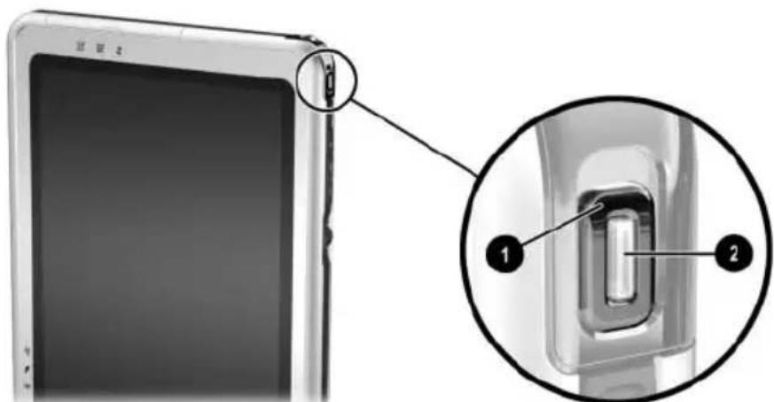
Identifying the power switch and the power/standby light
When External Power Is Available
To resolve a low-battery condition, select one of the following options:
Plug the AC adapter cable into the tablet PC, then plug the power cord into the AC adapter and into an AC electrical outlet. Plug an optional Automobile Power Adapter/Charger into the tablet PC and into a vehicle cigarette lighter receptacle. Plug an optional Auto/Air Cable into the tablet PC and into the in-seat power supply available on some commercial aircraft. (An optional Auto/Air Cable can run the tablet PC but cannot charge a battery pack.)
When No Power Source Is Available
To resolve a low-battery condition, initiate Hibernation. Or, save your work, then shut down the tablet PC.
Initiating and Resuming from Standby or Hibernation
For more information about Standby and Hibernation, refer on this CD to the Software Guide, "Power" chapter.
To initiate Standby, slide and release the power switch. To resume from Standby, slide and release the power switch. To initiate Hibernation, select Start > Turn off Computer > Hibernate. If the Hibernate option is not displayed and an external keyboard is attached, press and hold shift. (When you press and hold shift, the Hibernate option replaces the Standby option in the Shut Down window.) To resume from Hibernation, slide and release the power switch.
For information about initiating Standby or Hibernation from the Q Menu, refer to the Software Guide, “Q Menu and Desktop Video Profiles” chapter on this CD.
Calibrating a Battery Pack
When to Calibrate
Calibrate an in-use battery pack whenever battery charge displays seem inaccurate or whenever the battery pack has not been used for one month or more. It should not be necessary to calibrate any battery pack, even if it is heavily used, more than once a month. It is not necessary to calibrate a new battery pack before first use.
How to Calibrate
Calibration requires three steps:
■ “Charging the Battery Pack” ■ “Discharging the Battery Pack” ■ “Recharging the Battery Pack”
To initiate an unattended calibration in an optional Battery Charger or Multibattery Charger, follow the instructions included with the charger.
To calibrate a battery pack manually, follow the instructions in the following sections.
Charging the Battery Pack
You can charge the battery pack while the tablet PC is on or off, but the battery pack will charge faster while the tablet PC is off.
To charge the battery pack:
- Insert the battery pack into the tablet PC.
- Connect the tablet PC to external power. (The battery light turns on.) To connect the tablet PC to external power, use any of the following methods:
Plug the AC adapter cable into the tablet PC, then plug the power cord into the AC adapter and into an AC electrical outlet.
Plug an optional Automobile Power Adapter/Charger into the tablet PC and into a vehicle cigarette lighter receptacle.
- Leave the tablet PC connected to external power until the battery pack is fully charged. (The battery light turns off.)
Discharging the Battery Pack
The tablet PC must remain on while the battery pack is being discharged. The battery pack can discharge whether or not you are using the tablet PC, but will discharge faster while the tablet PC is in use.
If you plan to leave the tablet PC unattended during the discharge, save your work before beginning the discharge procedure.
If you use the tablet PC occasionally during the discharge procedure and have set energy-saving timeouts, expect the following performance from your system during the discharge process:
The monitor will not turn off automatically. Hard drive speed will not decrease automatically while the tablet PC is idle. System-initiated Standby will not occur. System-initiated Hibernation will not occur until the battery has discharged to a critical low-battery condition.
To fully discharge a battery pack:
- When the battery light turns off indicating that the battery pack is fully charged, select Start > Control Panel > Performance and Maintenance icon > Power Options icon > Power Schemes tab.
- Record the 2 settings in the Plugged In column and the 2 settings in the Running On Batteries column so that you can reset them after the calibration.
- Change the settings in both columns to Never.
- Select the OK button.
- Disconnect the tablet PC from the external power source, but do not turn off the tablet PC.
- Run the tablet PC on battery power until the battery pack is fully discharged. (The battery light begins to flash when the battery pack has discharged to a low-battery condition. When the battery pack is fully discharged, the tablet PC initiates Hibernation and the power/standby light turns off.)
Recharging the Battery Pack
- Connect the tablet PC to external power, then leave the tablet PC connected to external power until the battery pack is fully recharged. (The battery light turns off.) You can use the tablet PC while the battery pack is recharging but the battery pack will charge faster if the tablet PC is off.
- If the tablet PC is off, turn it on when the battery pack is fully charged and the battery light turns off.
- Select Start > Control Panel > Performance and Maintenance icon > Power Options icon > Power Schemes tab.
- Referring to the settings you recorded earlier, reenter your settings for the 2 options in the Plugged In column and the 2 options in the Running On Batteries column.
- Select the OK button.
Battery Conservation Procedures and Settings
Using the battery conservation procedures and settings described in the following sections extends the time that a battery pack can run the tablet PC from a single charge.
Conserving Power as You Work
To conserve power as you use the tablet PC:
■ Turn off wireless and local area network (LAN) connections and exit modem applications when you are not using them. ■ Detach, disconnect, stop, or remove unpowered external devices that you are not using. Such devices include a PC Card, an SD Card, or a tablet PC keyboard. ■ Use the Brightness item on the Q Menu to lower and raise screen brightness quickly. ■ Use optional powered speakers instead of the internal speakers, or use volume controls to mute, restore, raise, and lower system volume quickly. ■ If you leave your work, initiate Standby or Hibernation or shut down the tablet PC.
Selecting Power Conservation Settings
To set the tablet PC to conserve power:
■ Select a short wait for the screen saver and select a screen saver with minimal graphics and motion. To access screen saver settings, select Start > Control Panel > Appearance and Themes icon > Display icon > Screen Saver tab. ■ Follow the instructions on this CD in the Software Guide, "Power" chapter, to select a power scheme with low power-use settings.
Storing a Battery Pack
If the tablet PC will be unused and unplugged for more than one month, remove and store the battery pack.

CAUTION: To prevent damage to a battery pack, do not expose it to high temperatures for extended periods of time.
High temperatures accelerate the self-discharge rate of a stored battery pack. To prolong the charge of a stored battery pack, place it in a cool, dry place.
Use the following table to estimate how long you can safely store a battery pack. The storage times provided are based on a battery pack that contains 50 percent of a full charge. A fully charged battery pack can be safely stored for longer; a battery pack containing a low charge can be safely stored for less time.
Calibrate a battery pack that has been stored for one month or more before using it.
| At These Temperatures | You Can Safely Store a Battery Pack for This Amount of Time | |
| Temperature Range °F | Temperature Range °C Storage Time | |
| 115°–140° | 46°–60° Less than 1 month | |
| 79°–113° | 26°–45° No more than 3 months | |
| 32°–77° | 0°–25° 1 year | |
Disposing of a Used Battery Pack

WARNING: There is a risk of fire and chemical burn if a battery pack is handled improperly. Do not disassemble, crush, or puncture a battery pack or short the contacts on a battery pack. Do not expose a battery pack to temperatures higher than 60°C (140°F), or dispose of a battery pack in water or fire.
When a battery pack has reached the end of its useful life, do not dispose of it in general household waste.
In North America, you can dispose of battery packs by using the HP battery recycling program. This program provides you with a postage-paid battery pack mailer preaddressed to a reclamation facility where the metals are recycled. For more information, call the telephone number listed for your location in the Worldwide Telephone Numbers booklet, included in English only with the tablet PC. In Europe, dispose of or recycle battery packs by using the public collection system or by returning them to HP, your authorized HP partners, or their agents. In other regions, refer to the Worldwide Telephone Numbers booklet, included in English only with the tablet PC, to contact an HP-authorized dealer, reseller, or service provider and request information about battery pack disposal.
For more information about battery pack precautions and disposal and the complete text of governmental agency notices, refer on this CD to the Regulatory and Safety Notices guide.
Finding More Power Information
For more information about using Standby and Hibernation, conserving power, setting power preferences, and using other power management features, refer on this CD to the Software Guide, “Power” chapter. For information about initiating Standby or Hibernation from the Q Menu, refer in the Software Guide to the “Q Menu and Desktop Video Profiles” chapter.
Adding a Drive to the System
Drives enable you to store and access data.
A standard removable drive can be added to the system by inserting the drive into the MultiBay of an optional External MultiBay or Docking Station. A USB drive can be added by connecting the drive to a USB connector on the tablet PC or on the Docking Station. Hard drive functions can also be added with a PC Card.
For information about connecting a USB drive, see Chapter 8, “External Device Connections.” For information about PC Cards, see Chapter 9, “Additional Hardware Options.” For general information about inserting and removing drives from an External MultiBay or Docking Station, refer to the documentation included with the device.
This chapter provides specific information about using drives in the tablet PC system.
The tablet PC hard drive bay supports only a 9.5-mm system hard drive. A MultiBay in an External MultiBay or Docking Station supports an additional 9.5-mm optional hard drive (inserted in a MultiBay Hard Drive Adapter) and the following 12.7-mm standard removable drives:
□ CD-ROM drive
□ DVD/CD-RW drive
□ CD-RW drive
Diskette drive
□ DVD-ROM drive
Understanding Drive Terms
Terms for Types of Drives
A hard drive is used for the permanent storage of data files and of software such as system files, applications, and drivers. The hard drive in the hard drive bay is the system hard drive, sometimes called the local disk. The system hard drive can be replaced, but cannot be used in a MultiBay. A hard drive is sometimes called a hard disk drive or HDD.
Diskette drives are often used to store or transport data. The tablet PC can read or write to any MultiBay diskette drive. A diskette drive is sometimes called a floppy disk drive, floppy drive, or FDD.
Optical drives include CD and DVD drives. Optical drives are used to store or transport data and to play music and movies. DVD media have higher capacities than CD media. The tablet PC can read or write to optical drives as described in the following table.
| Optical Drive Read Write |
| CD-ROM drive Yes No |
| CD-RW drive Yes Yes |
| DVD-ROM drive Yes No |
| DVD/CD-RW drive Yes Yes |
Terms for Drive Media
A diskette or disc that can be inserted or removed from a drive is referred to as a drive medium. In this guide, a diskette is inserted in a diskette drive, and a disc is inserted in an optical drive.
Caring for Drives
Drives are fragile system components that must be handled with care. Observe the following cautions when handling any drive.

CAUTION: To prevent damage to the tablet PC or a drive and loss of work:
■ Do not remove the system hard drive except for repair or replacement. For instructions, see Chapter 10, "Maintenance, Shipping and Travel." ■ Electrostatic discharge can damage electronic components. To prevent electrostatic damage to the tablet PC or a drive, follow these two precautions: (1) Discharge yourself from static electricity before handling a drive by touching a grounded metal object, and (2) Avoid touching the connectors on a drive. For more information about preventing electrostatic damage, refer to the Regulatory and Safety Notices guide on this CD. ■ Excessive force can damage drive connectors. When you insert a drive, use only enough force to seat the drive. ■ Handle a drive carefully. Do not drop it. ■ Avoid exposing a hard drive or a diskette to devices with magnetic fields. Products with magnetic fields include video and audio tape erasure products, monitors, and speakers. Security devices with magnetic fields include airport walk-through devices and security wands. The airport security devices that check carry-on luggage, usually while it is placed on a conveyor belt, use x-rays instead of magnetism and will not damage a hard drive or a diskette. ■ Do not spray a drive with cleaners. ■ Avoid exposing a drive to liquids or temperature extremes. If you mail a drive, ship it in packaging that protects it from shock, vibration, temperature, and humidity. Label the package "FRAGILE."
Inserting or Removing Drive Media
For general information about inserting or removing a drive from a MultiBay, refer to the documentation included with an optional External MultiBay or Docking Station. This section provides information that is not provided with optional drives or MultiBays and that may be helpful to users unfamiliar with standard removable drives.
Inserting a CD or DVD
- Be sure the tablet PC is turned on.
- Press the media release button ① on the drive bezel to release the media tray, then pull the tray outward until it is fully extended ②.
- Position a CD or one-sided DVD over the tray label side up.
- Gently press the disc onto the tray spindle ③ until the disc snaps into place. Handle the disc by the edges, not the flat surfaces. (If the media tray is not fully extended, tilt the disc to position it over the tray spindle, then press it downward into position.)
- Close the media tray ④.

Inserting a CD or DVD into an optical drive
Removing a CD or DVD (with Power)
If power is available:
- Be sure the tablet PC is on.

Press the media release button ① on the drive bezel to release the media tray, then pull the tray outward until it is fully extended ②.
- Remove the disc from the tray ③ by gently pushing down on the spindle while pulling up on the outer edges of the disc. If the media tray is not fully extended, tilt the disc as you remove it. Handle the disc by the edges, not the flat surfaces.
- Close the media tray ④.
- Place the disc in a protective case.
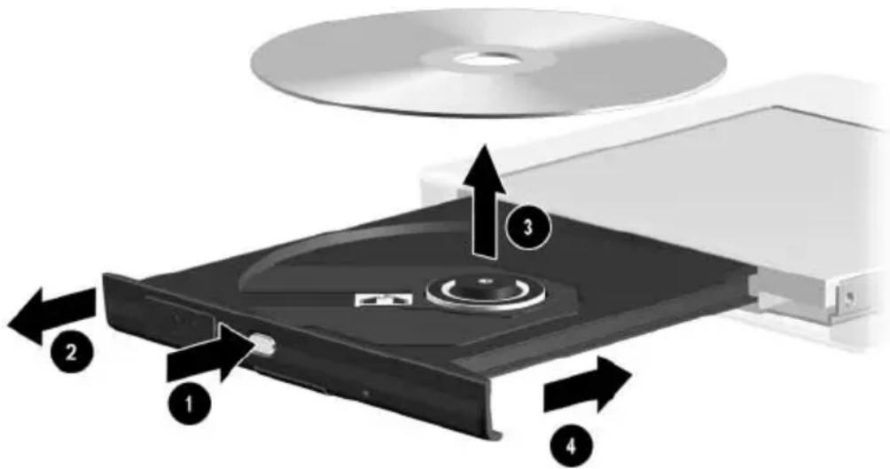
Removing a CD or DVD from an optical drive when power is available
Removing a CD or DVD (Without Power)

CAUTION: To prevent damage to the pen tip, do not insert the pen tip into the release access.
If the tablet PC is turned off or if no power is available, the media release button on the drive will not work. To remove a disc from an optical drive without using the media release button:
- Insert a small object like the end of a paper clip into the release access ① in the front bezel of the drive.
- Press gently on the paper clip until the media tray is released, then pull the tray outward until it is fully extended ②.
- Remove the disc from the tray ③. If the media tray is not fully extended, tilt the disc as you remove it. Handle the disc by the edges, not the flat surfaces.
- Close the media tray ④.
- Place the disc in a protective case.

Removing a CD or DVD from an optical drive when power is not available
Inserting a Diskette
To insert a diskette into a diskette drive, gently push the diskette, label side up, into the drive until it clicks into place.
The media eject button extends when the diskette is correctly inserted.

Identifying the media eject button on a diskette drive
Removing a Diskette
To remove a diskette from a diskette drive:
- Press the media eject button on the drive to eject the diskette.
- Pull the diskette from the drive.
- Place the diskette in a protective case.
Using Drive Media
Avoiding Standby and Hibernation

Initiating Standby or Hibernation while playing audio or video drive media may stop the play or diminish the quality of the play.
If Standby or Hibernation is accidentally initiated while a medium is in use, slide and release the power switch to resume from Standby or Hibernation, then restart the tablet PC.
For more information about Standby and Hibernation, refer on this CD to the Software Guide, “Power” chapter.
Displaying Media Contents
When you insert a diskette, CD, or DVD into the system, the tablet PC can play the medium, display its contents, take no action, or display a response prompt on the screen. You can set the responses of the tablet PC to the insertion of various types of media by using the operating system AutoPlay feature.
Setting AutoPlay Preferences
To set AutoPlay preferences:
- Select Start > My Computer.
- Right-click a drive.
- Select Properties > AutoPlay tab, then follow the instructions on the screen.
- To save your settings, select the OK button.
Displaying Media Contents Without Using AutoPlay
To display the contents of a drive medium when the contents are not displayed by AutoPlay:
- Insert the medium into the drive.
- Select Start > Run, then type:
explorer x:
(where X = the drive designation of the drive containing the medium).
- Select the OK button.

A drive designation is a letter of the alphabet that the tablet PC uses to identify the drive. To display the drive designation of every drive in the system, select Start > My Computer.
Caring for Drive Media

CAUTION: To prevent damage to drive media:
■ Do not open the metal shutter of a diskette or touch the disk within the diskette case. ■ Do not expose a diskette to a strong magnetic field, such as the security field used by a walk-through security device or a handheld security wand. ■ Clean a CD or DVD only with a disc cleaning kit. Disc cleaning kits are available from most electronics retailers.
Finding More Drive Software Information
All the software you need to play the types of CDs and DVDs supported by the tablet PC is included with the tablet PC. For information about this software, refer on this CD to the Software Guide, “CD and DVD Software” chapter.
In addition, a feature in the Setup utility enables you to set the tablet PC to start from a specified medium or device. For instructions, refer on this CD to the Software Guide, “Boot Order” chapter.
Adjusting Volume
Volume can be adjusted by using the Windows volume control icon, the Q Menu, or the volume adjustment available within some applications. Volume can be adjusted on the Q Menu without using a keyboard or the pen. For information about application volume features, refer to the application documentation.
Using the Volume Control Icon
To display the Windows volume control icon in the system tray:
- Select Start > Control Panel > Sounds, Speech, and Audio Devices icon > Sounds and Audio Devices icon.
- Select the Volume tab.
- Select the check box for Place Volume Icon In The Taskbar.
- Select the OK button.
- If the icon is not displayed, select the system tray icon for Show Hidden Icons.
To adjust, mute, or restore volume using the volume control icon, select the icon in the system tray. Then:
■ To increase or decrease volume, select the slide bar, then drag it upward or downward. ■ To mute or restore volume, select or clear the Mute check box.
To close the volume control pop-up window, click anywhere outside the window.
Using the Q Menu
To adjust, mute, or restore volume using the Q Menu:
- To open the Q Menu, press the Q menu button ①.
☐ To display the Windows volume control window, select the Volume tab.
☐ To mute or restore system volume, select the Mute On/Off tab. (Selecting the On/Off tab mutes system volume if it is on or restores system volume if it is muted.)
- To close the Q Menu, press the Q menu button, tap anywhere outside the Q Menu with the pen tip, or click an optional pointing device.
To select an item on the Q Menu without using a keyboard or the pen, press the Q menu button, rotate the jog dial ② upward or downward to scroll vertically through the items, then press the jog dial inward to select an item.
For more information about using the Q Menu, refer on this CD to the Software Guide, “Q Menu and Desktop Video Profiles” chapter.

Identifying the Q menu button and the jog dial
Using the Internal Speakers
The internal speakers play sound in stereo from applications, the operating system, games, drive media, the Internet, and other sources.
The internal speakers are disabled if:
Optional powered speakers or a headphone is connected to the audio-out jack on the tablet PC or an optional Docking Station. An optional mobile telephone headset is connected to the headset jack.
Attaching an optional tablet PC keyboard to the tablet PC or connecting a line-in device, such as a clock radio or MP3 player, to the tablet PC or to an optional Docking Station does not affect the performance of the internal speakers.
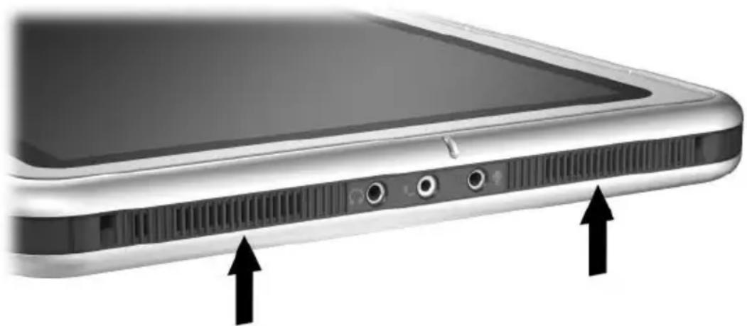
Identifying the internal speakers
Using the Internal Microphone
The internal microphone:
Has a standard sensitivity of -45 decibels. Can be used while a screen protector or an optional tablet PC keyboard is attached. A screen protector is provided with an optional Docking Station. Is disabled if:
An optional external microphone is connected to the microphone jack. An optional headset is connected to the headset jack.
If you are using speech recognition or other software that requires optimal sound quality, use an optional external microphone or headset. To access on-screen tutorials that include operating system speech features:
- Open Windows Explorer. To open Windows Explorer from the Start button, select Start > All Programs > Accessories > Windows Explorer.
- In Windows Explorer, select My Computer > Local Disk (C:) > WINDOWS > Help > latute.hta.
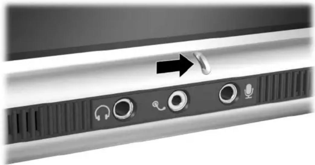
Identifying the internal microphone
Connecting an Audio Device Identifying Audio Jacks
The tablet PC has 3 audio jacks:
The audio-out jack ① connects stereo headphones or powered stereo speakers. The headset jack ② can support a headset, such as a mobile telephone headset with a microphone and a monaural ear piece. The microphone jack ③ supports a monaural external microphone.

Identifying the audio jacks
Using the Audio-Out Jack

WARNING: To reduce the risk of personal injury, adjust the volume before putting on headphones.

CAUTION: To prevent possible damage to an external device, do not plug a monaural plug into the audio-out jack.
When connecting a device to the audio-out jack:
■ Use only a 3.5-mm stereo plug. ■ For best sound quality, use 24-ohm to 32-ohm headphones.
When optional powered speakers or a headphone is connected to the audio-out jack on the tablet PC or an optional Docking Station, the internal speakers are disabled.
Using the Headset Jack
The headset jack can support a headset, such as a mobile telephone headset, that has a microphone, a monaural ear piece, and a 2.5-mm plug.
When a headset is connected to the headset jack, the internal microphone and speakers are disabled.
Using the Microphone Jack
The microphone jack supports a monaural microphone with a 3.5-mm plug.
A monaural electret condenser microphone is recommended. If you connect a stereo microphone, left channel sound will record on both channels.
When an optional headset or external microphone is connected to the tablet PC, the internal microphone is disabled.
Finding Audio and Video Software Information
For information about using audio and video software, refer to the Software Guide, “CD and DVD Software” chapter on this CD.
Internal Modem
The tablet PC has an RJ-11 telephone jack and preinstalled modem drivers.
A modem cable with RJ-11 connectors at each end is included with models that ship with an internal modem. If you purchased the tablet PC in a country where RJ-11 telephone jacks are not standard, a country-specific modem adapter is also included.
The internal modem supports:
■ All applications supported by the operating system. ■ V.34 ITU (International Telecommunications Union) analog modem recommendations for speeds up to 33.6 Kbps. ■ V.44 data compression algorithm. ■ V.90/V.92 ITU digital/analog modem pair recommendations for speeds up to 56 Kbps.

The digital/analog modem pair rates allow faster downloads only from compliant digital sources. Maximum achievable download rates are currently unknown, may not reach 56 Kbps, and will vary with line conditions. Maximum achievable upload rates are limited to 48 Kbps, may not reach 48 Kbps, and will vary with line conditions.
Connecting the Modem
Selecting Connectors
The modem must be connected to an analog telephone line.

WARNING: To reduce the risk of electric shock, fire, or damage to the equipment, do not plug a telephone cable into the RJ-45 network jack.

CAUTION: Jacks for digital PBX systems may resemble RJ-11 telephone jacks, but are not compatible with the modem.
Jacks for analog telephone lines and procedures for connecting the modem vary by country:
■ If you are connecting the modem in a country where RJ-11 telephone jacks are standard, follow the instructions in the “Connecting the Modem to an RJ-11 Jack” section, next in this chapter.
■ If you are connecting the modem in a country where RJ-11 telephone jacks are not standard, a modem adapter specific to the country in which you purchased the tablet PC is included with the tablet PC. Follow the instructions in the “Connecting the Modem with an Adapter” section, later in this chapter.
If you plan to use the modem outside the country in which you purchased the tablet PC, you can purchase adapters specific for the countries on your itinerary from most computer or electronics retailers. For information about using country-specific software configurations, see the “Setting Country Preferences” section, later in this chapter.
Connecting the Modem to an RJ-11 Jack
To connect the modem to an analog telephone line that has an RJ-11 telephone jack:
- To access the RJ-11 jack ① on the tablet PC, open the upper panel of the tablet PC.
- If the modem cable has noise suppression circuitry ②, which prevents interference with TV and radio reception, orient the circuitry end of the cable toward the tablet PC.
- Plug the cable into the RJ-11 telephone jack ③ (not the RJ-45 network jack) on the tablet PC.
- Plug the modem cable into an RJ-11 telephone jack ④ (not into an RJ-45 network jack or a PBX jack).
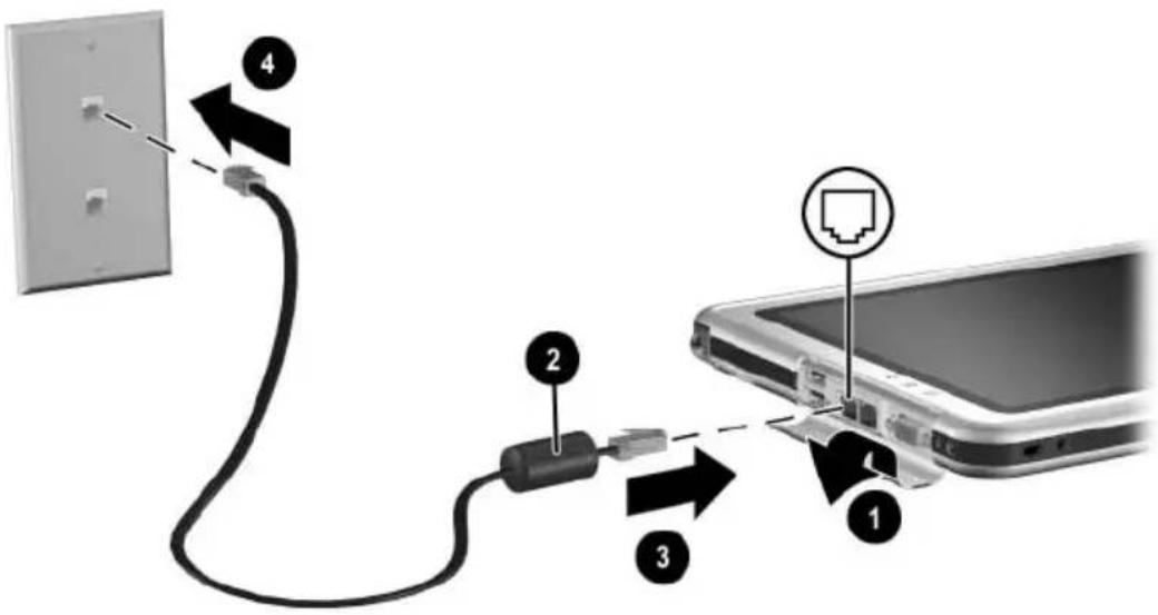
Connecting the modem to an RJ-11 telephone wall jack (Telephone wall jacks vary in appearance by region.)

WARNING: To reduce the risk of electric shock, disconnect the modem from the telephone network before accessing an internal compartment of the tablet PC. Internal compartments include the memory and Mini PCI compartment and the hard drive bay.
Connecting the Modem with an Adapter
To connect the modem to an analog telephone line that does not have an RJ-11 telephone jack:
- To access the RJ-11 jack ①, open the upper panel of the tablet PC.
- If the modem cable has noise suppression circuitry ②, which prevents interference with TV and radio reception, orient the circuitry end of the cable toward the tablet PC.
- Plug the modem cable into the RJ-11 telephone jack ③ (not the RJ-45 network jack) on the tablet PC.
- Plug the modem cable ④ into the country-specific modem adapter.
- Plug the country-specific modem adapter ⑤ into the telephone jack.

Connecting the modem with a modem adapter (Telephone wall jacks vary in appearance by region.)

WARNING: To reduce the risk of electric shock, disconnect the modem from the telephone network before accessing an internal compartment of the tablet PC. Internal compartments include the memory and Mini PCI compartment and the hard drive bay.
Setting Country Preferences
The internal modem is configured to function in and meet the operating standards of the country in which you purchased the tablet PC. To use the internal modem in other countries, you must add country-specific modem configurations.
Displaying the Current Country Configuration
To display the current country configuration, select Start > Control Panel > Date, Time, Language, and Regional Options category > Regional and Language Options icon > Regional Options tab. The current country configuration of the modem is displayed in the Location panel.
Adding a Country Configuration

CAUTION: To prevent loss of your current country configuration, do not delete or replace your current country configuration. Additional country configurations can be added without deleting the current configuration.

CAUTION: To prevent modem malfunction and violation of telecommunications regulations and laws, use the modem only with the country configuration for the country in which you are using the modem.
To add a country configuration:
- Select Start > Control Panel > Network and Internet Connections category.
- From the See Also menu in the left column of the window, select Phone and Modem Options > Dialing Rules tab.

If you do not see the Dialing Rules tab when you select Phone and Modem Options, complete the fields in the Location Information wizard. After you save the settings on the Location Information wizard, the Dialing Rules tab is displayed.
- Select the New button, then type a name for the new location in the Location Name field.
- Select a country or region for the new location from the Country/Region list. If you select a country or region that is not supported by the modem, the country configuration defaults to USA or UK.
- Select the OK button > OK button.
Solving Travel Connection Problems
If you experience connection problems while using the modem outside the country in which you purchased the tablet PC, the following suggestions may be helpful.
Before changing any settings, you may want to write down your current settings so you can quickly replace those settings when you return home.
Check the Line
The modem requires an analog, not a digital, telephone line. A line described as a PBX line is usually a digital line. A telephone line described as a data line, fax machine line, modem line, or standard telephone line is probably an analog line.
Check the Dialing Mode
Dial a few digits on the telephone, then listen for clicks or tones. Clicks indicate that the telephone line supports pulse dialing; tones indicate that the telephone line supports tone dialing. To set the internal modem to support either pulse or tone dialing:
- Select Start > Control Panel > Network and Internet Connections category.
- From the See Also menu in the left column of the window, select Phone and Modem Options > Dialing Rules tab.
- Select your location, then select the Edit button.
- Select the Tone or Pulse radio button.
- Select the OK button > OK button.
Check the Telephone Number
Dial the telephone number on the telephone, verify that the remote modem is answering, then hang up.
Check the Dial Tone
If the modem receives a dial tone it does not recognize, it will not dial and will display a No Dial Tone error message.
■To set the modem to ignore all dial tones before dialing:
- Select Start > Control Panel > Network and Internet Connections category.
- From the See Also menu in the left column of the window, select Phone and Modem Options > Modems tab.
- Select your modem > Properties button > Modem tab.
- Clear the Wait For Dial Tone Before Dialing check box.
- Select the OK button > OK button.
■If you continue to receive the No Dial Tone error message after clearing the check box:
- Select Start > Control Panel > Network and Internet Connections category.
- From the See Also menu in the left column of the Network and Internet Connections window, select Phone and Modem Options > Dialing Rules tab.
- Select your location, then select the Edit button.
- Select your location from the Country/Region list.

If you select a country or region that is not supported by the modem, the country configuration defaults to USA or UK.
- Select the OK button.
- In the Phone and Modem Options window, select the Modems tab.
- Select your modem > Properties button > Modem tab.
- Clear the Wait For Dial Tone Before Dialing check box.
- Select the OK button > OK button.
Accessing Communication Software
To access preinstalled modem software, including software for terminal emulation and data transfer, select Start > All Programs > Accessories > Communications, then select an application, wizard, or utility.
Finding AT Command Information
It is not necessary to use AT commands with most modem software. If you prefer to use AT commands, refer on this CD to:
■ Modem Command Guidelines for information about accessing Hyperterminal, identifying the modem in your tablet PC, and using AT commands. ■ The Soft Modem AT Command Reference Manual for the AT commands supported by your modem. This guide is provided in English only.
Network Connections
The tablet PC has an RJ-45 network jack. Network tablet PC models also have an internal NIC (network interface card), preinstalled network drivers, and a network cable.
The tablet PC can be connected to a network whether or not the internal modem is connected to a telephone line.
If your tablet PC is connected to a network, you may want to confer with your network administrator before changing network settings.
The tablet PC supports network speeds up to 10 Mbps when connected to a 10BaseT network and 100 Mbps when connected to a 100BaseTX network.
Connecting the Network Cable
A network cable has an 8-pin RJ-45 network connector at each end and may contain noise suppression circuitry, which prevents interference with TV and radio reception.
- To access the tablet PC RJ-45 network jack ①, open the upper panel of the tablet PC.
- Orient the end of a network cable with noise suppression circuitry ② toward the tablet PC.
- Plug the network cable into the tablet PC RJ-45 network jack ③.
- Plug the other end of the cable into the network RJ-45 jack ④.

Connecting a network cable

WARNING: To reduce the risk of electric shock, disconnect the network cable before accessing an internal compartment of the tablet PC. Internal compartments include the memory and mini PCI compartment and the hard drive bay.
Turning a Network Connection Off and On
To conserve power, turn off a network connection you are not using.
To turn off a network connection, log off the network, then disconnect the network cable.
To turn on a network connection, connect the network cable, then log on to the network.
Using the LAN Connection Lights
The 2 LAN connection lights indicate the status of a network connection:
Both lights off: The tablet PC is not connected to a LAN.
Both lights on: The tablet PC is connected to a LAN with a 100 Mbps link.
Green light on and yellow light off: The tablet PC is connected to a LAN with a 10 Mbps link.

Identifying the LAN connection lights
Accessing the Network at Startup
To connect to a PXE (Preboot eXecution Environment) or RPL (Remote Program Load) server during startup, you must respond to the Network Service Boot prompt each time you want to connect to the server as the tablet PC starts or restarts.
To set the tablet PC to display the Network Service Boot prompt each time it is started or restarted, you must enable the internal NIC for startup.
Enabling a NIC for Startup
An internal NIC is enabled for startup in the Setup utility.
- To open the Setup utility, turn on or restart the tablet PC. While the HP logo is displayed and a cursor is flashing in the upper right corner of the screen, press the esc button on the tablet PC or press F10 on an optional keyboard.
- To change the language, select Advanced > Languages.
To navigate and select without using an optional keyboard, rotate the jog dial to scroll and press the jog dial inward to select.
To navigate and select using an optional keyboard, use the arrow and enter keys.
- Select Advanced menu > I/O Device Configuration, then enable PXE/Remote Boot.
- To save your preference and exit the Setup utility, select File > Save Changes and Exit, then follow the instructions on the screen.
Your preference is set as you exit the Setup utility and is in effect when the tablet PC restarts.
Responding to a Network Service Boot Prompt
After the internal NIC has been enabled for startup, the Network Service Boot prompt is displayed very briefly in the lower right corner of the screen each time the tablet PC is started or restarted.
To connect to a network by responding to the prompt, use either of the following procedures:
Press the tab button on the tablet PC. Press F12 on an optional keyboard. To press F12 on the tablet PC keyboard, press Fn+F11/F12.
Finding Wireless LAN Information
The tablet PC supports wireless LAN provided through a mini PCI board, a PC Card, or an SD Card. A wireless LAN PC Card or an SD Card is optional. A wireless mini PCI board may be preinstalled.
Information about using a preinstalled wireless LAN board is provided on the Documentation Library Wireless LAN CD included with your tablet PC. Information about the Bluetooth wireless option is provided on the Documentation Library Bluetooth CD included with your tablet PC. Information about Microsoft's Wireless LAN configuration utility is available in the Help & Support Center, which is accessible from the Start Menu.
If you purchase a wireless device as an option, documentation about the device is included with the option.
External Device Connections
Standard Device
The jacks and connectors described in this guide support standard external devices.
For information about which jack or connector to use, refer to the documentation included with the device. For information about installing or loading any software required by the device, refer to the device documentation, the operating system Help files, or the device manufacturer's Web site.
To connect a standard external device to the tablet PC:
- If you are connecting a powered device, be sure the device is turned off.
- Connect the device to a jack or connector on the tablet PC.
- If you are connecting a powered device, plug the device power cord into a grounded electrical outlet.
- Turn on the device.

If a properly connected display device does not display an image, try pressing the Q menu button > Internal and External item or External Only item to switch the image to the new device.
To disconnect a standard external device from the tablet PC, turn off the device (if it is powered), then disconnect the device from the tablet PC.
USB Device
USB is a hardware interface that can be used to connect external devices such as a USB keyboard, mouse, drive, printer, scanner, or hub to the tablet PC or an optional Docking Station.
A USB device functions in the system in the same way as a comparable non-USB device. The USB connectors support USB 2.0- or 1.1-compliant devices.
A USB hub is a connecting device that can be powered or unpowered. USB hubs can be connected to a USB connector on the tablet PC or on an optional Docking Station or to other USB devices. Hubs support varying numbers of USB devices and are used to increase the number of USB devices in the system.
Powered hubs must be connected to external power. Unpowered hubs must be connected either to a USB connector on the tablet PC or to a port on a powered hub.
Some USB devices may require additional support software, which is usually included with the device. For software information about a specific device, refer to the documentation included with the device.

Identifying the 2 USB connectors on the tablet PC
Tablet PC Keyboard
A tablet PC keyboard, which includes a numeric keypad, can be used with the tablet PC.
For information about using the tablet PC keyboard pointing device, keypad, and F11/F12 key, see the “Pen, Command Controls and Keyboards” chapter, “Tablet PC Keyboard” section.
The tablet PC can be attached or detached from the keyboard while it is on, off, in Standby, or in Hibernation.
Attaching the Tablet PC to the Keyboard
To attach the tablet PC to the keyboard:
- Place the keyboard on a flat surface with the keyboard keys facing you.
- Rotate the attachment features on the rotation disk toward the keyboard.
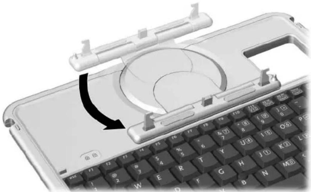
Rotating the attachment features toward the keyboard
- Position the tablet PC horizontally above the keyboard, with the front of the tablet PC facing the keyboard.
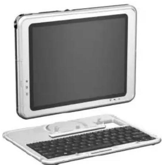
Positioning the tablet PC above the keyboard
- Align the 4 slots on the tablet PC with the keyboard connector, alignment key, and 2 keyboard hooks on the keyboard ①, then press the tablet PC downward until it snaps into place ②.

Attaching the tablet PC to the keyboard
Adjusting the Tablet PC and Keyboard
To tilt the tablet PC screen to a comfortable viewing angle, push gently on the top of the tablet PC.

Tilting the tablet PC on the keyboard
Closing the Tablet PC and Keyboard
To close the tablet PC and keyboard as you would close the display on a standard notebook:
- Rotate the tablet PC clockwise until it snaps into place facing away from the keyboard.
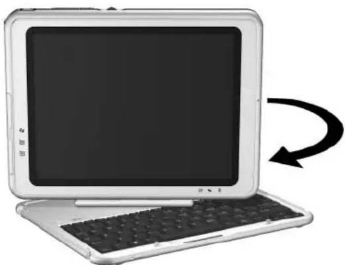
Rotating the tablet PC toward the back of the keyboard 2. Tilt the tablet PC downward onto the keyboard.

Closing the tablet PC and keyboard
Transporting the Tablet PC and Keyboard
If you are transporting the tablet PC and keyboard while they are not attached, be sure the rotation disk is in the default position. (The attachment features are at the rear of the tablet PC and the HP logo is right side up when you are facing the keyboard.)
If you are transporting the tablet PC and keyboard while they are attached, you may want to use the keyboard latch. The keyboard latch locks the tablet PC to the keyboard while the tablet PC and keyboard are closed.
To lock the tablet PC to the keyboard while the tablet PC is closed, slide the keyboard latch to the right ①.
To release the tablet PC from the closed position, push the keyboard latch to the left, then slide and hold the latch toward the left as you open the tablet PC ②.
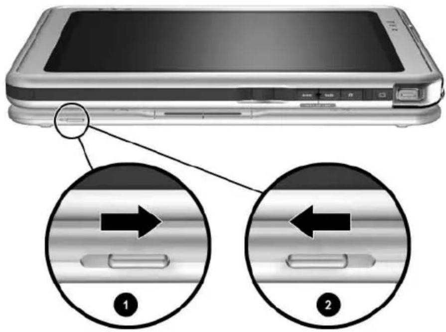
Using the keyboard latch
Detaching the Tablet PC from the Keyboard
To detach the tablet PC from the keyboard:
- If the tablet PC is closed, open the tablet PC, then rotate the tablet PC so the screen is facing the keyboard in the notebook position.
If the tablet PC does not open easily from the keyboard, it may be secured to the keyboard with the keyboard latch. For release instructions, see the “Transporting the Tablet PC and Keyboard” section, earlier in this chapter.

Opening the tablet PC to the notebook position
- Rotate the tablet PC and keyboard so the back of the tablet PC and the keyboard are facing you.

Positioning the tablet PC and keyboard to detach the tablet PC
- To detach the keyboard, slide and hold the attachment release switch ① on the tablet PC as you lift the tablet PC away from the keyboard ②.
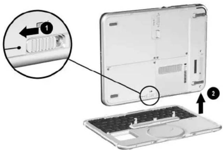
Detaching the tablet PC from the tablet PC keyboard
Cable Lock
Loop the cable around a secure object, then insert the cable lock key ① into the security cable lock ②. Then insert the cable lock into the security cable slot ③ on the tablet PC.

Connecting an optional cable lock

The purpose of security solutions is to act as a deterrent. These solutions do not prevent the product from being mishandled or stolen.
Additional Hardware Options
Obtaining Upgrades
To order or learn more about optional hardware upgrades and accessories, visit the HP Web site at http://www.hp.com. The hardware upgrade area is English only. Or, refer to the Worldwide Telephone Numbers booklet, included in English only with the tablet PC, to contact an HP-authorized dealer, reseller, or service provider.
For information about obtaining and installing software updates and upgrades, refer on this CD to the Software Guide.
Using a PC Card
A PC Card is a credit card-sized accessory designed to conform to the standard specifications of the Personal Computer Memory Card International Association (PCMCIA). The tablet PC supports both 32-bit CardBus and 16-bit PC Cards.
A PC Card can be used to add modem, sound card, memory, storage, wireless communication, or digital camera functions to the tablet PC. A PC Smart Card Reader or a biometric identification PC Card can add security.

The purpose of security solutions is to act as a deterrent. These solutions do not prevent the product from being mishandled or stolen.
Selecting a PC Card
A Type I or Type II PC Card can be used. A Type III PC Card will not fit into the PC Card slot of the tablet PC. (Types I, II, and III PC Cards vary by thickness, with Type III being the thickest.)
Zoomed video cards are not supported.
Configuring a PC Card

CAUTION: If you install all of the software or any of the enablers provided by a PC Card manufacturer, you may not be able to use other PC Cards. If you are instructed by the documentation included with a PC Card to install device drivers:
Install only the device drivers for the Microsoft Windows XP Tablet PC Edition operating system.
Do not install other software, such as card services, socket services, or enablers, that may also be supplied by the PC Card manufacturer.
Inserting a PC Card

CAUTION: To prevent damage to the PC Card connectors, use minimal force when inserting a PC Card into the PC Card slot.
- Hold the PC Card label-side up with the connector facing the tablet PC.
- Gently push the card into the PC Card slot until the card is seated.

Inserting a PC Card
Stopping and Removing a PC Card

CAUTION: To prevent loss of work or an unresponsive system, stop a PC Card before removing it.

An inserted PC Card uses power even when it is not in use. To conserve power, stop a PC Card when you are not using it.
- Close all applications and complete all activities that are supported by the PC Card.
- To stop a PC Card, select the system tray icon for Safely Remove Hardware, then follow the instructions on the screen. (To display the Safely Remove Hardware icon, select the system tray icon for Show Hidden Icons.)
- To release the PC Card, press the PC Card eject button ①.
- Gently pull out the PC Card ②.

Removing a PC Card
Using an SD Card
An SD Card is smaller than a PC Card, but can add similar functions to the tablet PC system. Most commonly, an SD Card is used to add backup, storage, wireless network, fax/modem, or cellular telephone functions.
When using an SD Card, HP recommends that you connect the system to external power whenever possible. Some SD Cards use large amounts of power and can quickly drain a battery pack.


CAUTION: To prevent loss of work or damage to an SD Card:
- Do not save your work to an SD Card unless the tablet PC is connected to external power or you are certain that the battery pack has enough charge remaining to complete the operation.
■Do not shut down the tablet PC or remove the SD Card until all activities supported by the card are complete.
Configuring an SD Card
If an SD Card manufacturer instructs you to install card-specific drivers, be sure to install only the drivers supported by the Windows XP Tablet PC Edition operating system. If you are unsure of driver compatibility, contact the SD Card manufacturer.
Inserting an SD Card

CAUTION: To prevent damage to the SD Card connectors, use minimal force when inserting an SD Card into the SD Card slot.
- Hold the SD Card label-side up with the connector facing the tablet PC.
- Gently push the card into the SD Card slot until the card is seated.

Inserting an SD Card
Stopping and Removing an SD Card

CAUTION: To prevent loss of work or an unresponsive system, stop an SD Card before removing it.

An inserted SD Card uses power even when it is not in use. To conserve power, stop an SD Card when you are not using it.
- Close all applications and complete all activities that are supported by the SD Card.
- To stop an SD Card, select the system tray icon for Safely Remove Hardware, then follow the instructions on the screen. (To display the Safely Remove Hardware icon, select the system tray icon for Show Hidden Icons.)
- To release the SD Card, press inward on the SD Card ①.
- Gently pull out the SD Card ②.

Removing an SD Card
Increasing Memory
You can increase the amount of RAM (random access memory) in the tablet PC with an optional PC Card or with an optional memory module.
The tablet PC has one user-accessible memory slot. The slot supports a PC133-compliant 128-megabyte, 256-megabyte, or 512-megabyte memory module.
Displaying Memory Information
When the amount of RAM in the system increases, the operating system increases the hard drive space reserved for the hibernation file.
If you experience problems with Hibernation after increasing RAM, verify that your hard drive has enough free space for the larger hibernation file.
■To display the amount of RAM in the system:
Select Start > Control Panel > Performance and Maintenance icon > System icon > General tab.
■To display both the amount of free space on your hard drive and the amount of space required by the hibernation file:
Select Start > Control Panel > Performance and Maintenance icon > Power Options icon > Hibernate tab.
Removing or Inserting a Memory Module

WARNING: To prevent exposure to electric shock, work only in the memory and mini PCI compartment during this procedure. The hard drive bay and the memory and mini PCI compartment are the only user-accessible internal compartments on the tablet PC. All other areas that require a tool to access should be opened only by an HP-authorized service provider.

WARNING: To prevent exposure to electric shock and damage to the tablet PC, shut down the tablet PC, unplug the power cord, and remove the battery pack before installing a memory module.

CAUTION: To prevent electrostatic discharge from damaging electronic components: Discharge static electricity from yourself by touching a grounded metal object before beginning this procedure. For more information about preventing electrostatic damage, refer on this CD to the Regulatory and Safety Notices guide.
- Be sure that you have followed the instructions in the preceding warnings and caution. If you are not sure whether the tablet PC is off or in Hibernation, slide and release the power switch. If your work returns to the screen, save your work, exit all applications, then shut down the tablet PC.
- Disconnect all external devices connected to the tablet PC.
- Disconnect the power cord.
- Remove the battery pack.
- If the tablet PC keyboard is attached to the tablet PC, detach the keyboard.
- Turn the tablet PC front side down.
- Remove the two memory and mini PCI compartment retaining screws ①.
- Slide, lift, then remove the memory and mini PCI compartment cover ②.

Opening the memory compartment
- Remove or insert the memory module.
To remove a memory module:
a. Release the retention clips on each side of the memory module ①. (The memory module tilts upward.) b. Grasp the edges of the memory module, then gently pull it out of the memory slot ②.
c. To protect a removed memory module, place it in an electrostatic-safe container.

Removing a memory module
To insert a memory module:
a. Align the keyed (notched) edge of the memory module with the keyed area in the memory slot ①. b. Press the memory module into the slot from a 45-degree angle until it is seated ②. c. Push the memory module downward until the retention clips snap into place ③.

Inserting a memory module
- Align the tabs on the memory compartment cover with the cover slots on the tablet PC ①, then press downward on the cover until it is seated.
- Reinsert the two retaining screws that secure the memory and mini PCI compartment cover to the tablet PC ②.

Replacing the memory compartment cover
Maintenance, Shipping and Travel
Maintaining Software
HP recommends that you:
■ Install all software updates as they become available. For instructions, refer on this CD to the Software Guide, "Software Updates and Restorations" chapter. ■ Install and use virus protection software. Antivirus software can be purchased from most computer or electronics retailers. ■ Back up your work and system software frequently.
☐ For information about using the operating system backup utility, select Start > Help and Support > Performance and Maintenance topic. In the upper left pane of the Performance and Maintenance window, select the Backing Up Your Data check box.
☐ For information about selecting optional backup software or hardware, consult with your authorized HP dealer, reseller, or service provider.
Protecting Hardware
To protect and prolong the performance of your hardware, observe the following cautions.

CAUTION: To prevent damage to your hardware or loss of work:
- Carry and store the tablet PC in the portfolio or an optional Executive Portfolio. ■ Do not place anything on top of the tablet PC, even when it is in a portfolio. ■ Use the tablet PC only on solid surfaces and in open areas. Do not allow a hard surface, such as an adjoining optional printer, or a soft surface, such as carpet, clothing, or bedding, to block the vent. ■ Protect the tablet PC from liquids and excessive moisture. ■ Do not expose the tablet PC to direct sunlight, extreme temperatures, or ultraviolet light for extended periods of time.
- Keep all hard drives and diskettes away from magnetic fields. Magnetic fields can corrupt data stored on hard drives and diskettes. If the tablet PC will be unused for one week or more, shut it down. If the tablet PC will be disconnected from external power for more than one month, shut down the tablet PC and remove the battery pack. For information about storing the battery pack, see Chapter 3, "Battery Packs."
Using Portfolios
To protect the tablet PC screen, HP recommends that you use or transport the tablet PC with a portfolio attached. A slim portfolio that protects the tablet PC or the tablet PC attached to an optional keyboard is included with the tablet PC.
An optional leather Executive Portfolio that provides additional protection, has slots for business cards, and accommodates additional items is available in most regions.
To obtain the Executive Slimline or Workstation Portfolio, refer to the Worldwide Telephone Numbers booklet included in English only with the tablet PC to contact your authorized HP dealer, reseller, or service provider.
Attaching a Portfolio
When you are using only the tablet PC, press the 2 tabs on the portfolio into the 2 universal attachment slots on the tablet PC.
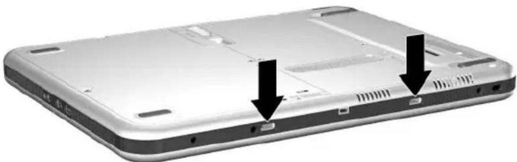
Identifying the universal attachment slots on the tablet PC
When you are using the tablet PC attached to the tablet PC keyboard, press the 2 tabs on the portfolio into the 2 universal attachment slots on the keyboard.

Identifying the universal attachment slots on a tablet PC keyboard
Detaching a Portfolio
To release a portfolio from the tablet PC, slide and hold the attachment release switch on the tablet PC.

Sliding the attachment release switch on the tablet PC
To release a portfolio from the tablet PC keyboard, slide and hold the attachment release switch on the tablet PC keyboard.

Sliding the attachment release switch on the tablet PC keyboard
Cleaning Hardware

WARNING: To prevent electric shock or damage to components, do not attempt to clean the tablet PC until you:
■ Shut down the tablet PC. ■ Disconnect the tablet PC from external power. ■ Disconnect all powered external devices from the tablet PC.

CAUTION: Do not spray liquids on the tablet PC. Household solvents can permanently damage tablet PC surfaces, and any liquid can damage the internal components of the tablet PC or an optional keyboard.
Cleaning the Screen
To remove smudges and lint, clean the screen with a soft, lint-free cloth dampened with water or a glass cleaning liquid. Antistatic screen cleaner or premoistened antistatic wipes may also be used.
Cleaning a Tablet PC Keyboard
Dust, lint, and other debris can affect the performance of an optional tablet PC keyboard. To prevent sticking or nonfunctioning keys, clean the keyboard frequently using a can of compressed air with a straw extension. Blow the compressed air around the base of each key.
To clean the key surfaces, use a soft, damp, lint-free cloth.

Using a household vacuum cleaner to clean the keyboard may deposit, rather than remove, debris.

Cleaning a tablet PC keyboard with a can of compressed air
Replacing Hardware
Replacing the System Hard Drive
The system hard drive is the hard drive in the hard drive bay. Remove the system hard drive only for repair or replacement.

CAUTION: To prevent an unresponsive system and loss of work:
■ Shut down the tablet PC before removing the system hard drive. Do not remove the system hard drive while the tablet PC is powered on, in Standby, or in Hibernation.
To verify that the tablet PC is off and not in Hibernation, slide and release the power switch. If your work returns to the screen, save your work, exit all applications, then shut down the tablet PC.
- Save your work, then shut down the tablet PC.
- Turn the tablet PC front side down.
- Remove the 2 hard drive bay cover retaining screws ①.
- Slide, lift, then remove the hard drive bay cover ②.

Removing the hard drive bay cover
CAUTION: The connector pins on the hard drive are designed to support only the minimal insertions or removals that may be required for repair or replacement. To prevent damage to the hard drive connectors, be careful not to bend them while removing the hard drive.
- To remove the hard drive, gently disengage the drive connectors ① by sliding the hard drive toward the lower edge of the tablet PC.
- Remove the drive from the bay ②.

Removing a system hard drive from the hard drive bay
- To insert the replacement hard drive, lower the drive into the hard drive bay ①, then slide the connectors on the hard drive toward the connectors in the bay ② until the connectors engage and the drive is seated.

Inserting a system hard drive into the hard drive bay
- Align the tabs on the hard drive bay cover with the cover slots on the tablet PC ①, then press downward on the cover until it is seated.
- Reinsert the 2 retaining screws that secure the cover to the tablet PC ②.

Replacing the hard drive bay cover
Replacing a Pointing Stick Cap
Two pointing stick replacement caps are included with an optional tablet PC keyboard. To replace a worn pointing stick cap:
- If the keyboard is attached to the tablet PC, shut down the tablet PC.
- Gently pull off the used pointing stick cap.
- Push a replacement cap into place.

Replacing the pointing stick cap
Preparing the Tablet PC for Shipping or Travel
- Back up your work.
- Remove a PC Card or SD Card.
- Undock the tablet PC from an optional Docking Station.
- Turn off, then disconnect all optional external devices such as headphones or an External MultiBay. (It is not necessary to detach the tablet PC from the tablet PC keyboard.)
- Shut down the tablet PC.
- If the tablet PC will be disconnected from an external power source for more than one month, shut down the tablet PC, remove the battery pack, and store the battery pack in a cool, dry place.
- If you are shipping the tablet PC, insert it into a portfolio, place it in the original packing box or similar protective packaging, and label the package “FRAGILE.”
Traveling with the Tablet PC
Checklist for Travelers
■ Take along a backup of your work. Do not pack the backup with the tablet PC.
■ Carry the tablet PC with you. Do not check it with your luggage.
If you will have access to an optical drive, you may want to take along the Documentation Library CD. If not, HP suggests that you print and take with you the “Contacting HP” section later in this chapter.
■ Do not expose the tablet PC, a hard drive, or a diskette to a magnetic security detector.
☐ The security device that examines carry-on items placed on a conveyor belt uses x-rays and is safe for the tablet PC and all drive media.
☐ The walk-through security device and handheld security wands are magnetic and may damage the tablet PC, a hard drive, or a diskette.
If you plan to use the tablet PC during a flight, check with the airline in advance. In-flight tablet PC use is at the discretion of the airline.
If you expect to encounter climatic extremes, see the “Specifications” chapter, “Tablet PC Operating Environment” section.
If you are traveling internationally:
If you plan to use an internal modem, review Chapter 6, “Internal Modem” for information about using adapters and country configurations. You may want to print and take with you the “Solving Travel Connection Problems” section of that chapter if you are not bringing the Documentation Library CD. Check the computer-related customs regulations for each country on your itinerary. Consult with an electronics retailer or an HP authorized dealer, reseller, or service provider about power cord and adapter requirements for each location in which you plan to use the tablet PC. (Voltage, frequency, and plug configurations vary.) To contact an HP-authorized dealer, reseller, or service provider near you, refer to the Worldwide Telephone Numbers booklet included in English only with the tablet PC.

WARNING: To reduce the risk of electric shock, fire, or damage to the equipment, do not attempt to run the tablet PC with a voltage converter kit sold for appliances.
Contacting HP
Getting Help from the Internet
If you have Internet access, you can resolve most problems that may arise while traveling with the tablet PC by using HP Help and Support.
HP Help and Support provides links to specific areas of the HP Web site (http://www.hp.com) where you can:
Obtain all documentation included with your tablet PC as well as other information about your tablet PC such as specifications, white papers, and customer advisories. Initiate an online service event with an HP support specialist.
Download the latest drivers, utilities, and other software updates for your tablet PC. Subscribe to the HP Support Software CD.
To access these links and descriptions of the options they provide, select Start > HP Help and Support. The HP Help and Support menu is displayed in the left panel.
Not all links are available worldwide, and most sites are available in limited languages.
Getting Help Without Using the Internet
If you need help and cannot access the Internet:
To obtain troubleshooting information:
Refer to the Troubleshooting guide on this CD. Also refer to the “Solving Problems” chapter in the printed Startup Guide included with the tablet PC.
To obtain a list of worldwide Technical Support telephone numbers:
Select Start > Control Panel > Performance and Maintenance icon > System icon. Then, near the lower edge of the System Properties window, select the Support Information button.
Refer to the printed Worldwide Telephone Numbers booklet included in English only with the tablet PC.
Specifications
The information in this chapter may be helpful if you plan to use or transport the tablet PC internationally or in extreme environments.
Tablet PC and Tablet PC Keyboard Dimensions
| Dimension Metric U.S. |
| Height 2.1 cm 0.8 in |
| Width 21.0 cm 8.3 in |
| Depth 27.1 cm 10.8 in |
Tablet PC Operating Environment
| Factor Metric U.S. |
| Temperature |
| Operating 10° to 35° C 50° to 95° F |
| Nonoperating -10° to 60° C 14° to 140° F |
| Relative humidity (noncondensing) |
| Operating 10 to 90% 10 to 90% |
| Nonoperating 5 to 90% 5 to 90% |
| Maximum altitude (unpressurized) |
| Operating 3,048 m 10,000 ft |
| Nonoperating 9,144 m 30,000 ft |
Tablet PC Rated Input Power
The tablet PC operates on DC power, which can be supplied by an AC or DC power source.
| Input Power Rating | |
| Operating voltage 100–120/220–240 Vrms | |
| Operating current 1.7/0.85 A RMS | |
| Operating frequency range | 50 to 60 Hz AC |
| When powered by a DC source | 18.5 V MAX |
| This product is designed for IT power systems in Norway with phase-to-phase voltage not exceeding 240 Vrms. | |
Modem Specifications
This tablet PC has been tested and found to comply with the limits for a Class B digital device.
| Factor Specification | ||
| Temperatures | ||
| Operating 10° to 40°C (50° to 104°F) | ||
| Nonoperating -20° to 60°C (-4° to 140°F) | ||
| Relative Humidity (noncondensing) | ||
| Operating 10 to 90% | ||
| Nonoperating 5 to 90% | ||
| Interfaces Communications | Standard RJ-11 connector | |
| connector | ||
| Host Connector mini PCI Type III | ||
| Power Requirements +3.3 volts ±5%, +3.3 vaux ±5% | ||
Finding More Environmental Information
The specifications in this chapter contain information about exposing the tablet PC to environmental extremes.
For similar information about storing battery packs, see the “Battery Packs” chapter, “Storing a Battery Pack” section.
For information about exposing the tablet PC to sunlight, ultraviolet light, x-rays, or magnetic fields, see the “Maintenance, Shipping and Travel” chapter, “Protecting Hardware” section.
Index
A
AC adapter
AC power connector 1–11
connecting 3–15
disconnecting 3–1
identifying 1–22
light 1–2
AC power connector 1–11
AC power, switching to and from 3–1
adapter
for AC power cord. See AC adapter
for connecting AC adapter to electrical outlet (Japan only) 1–22
for modem. See modem adapter adjustment, tilt 1–26
airport security devices 10–15 alignment
key 1-26
key slot 1–9
notches, docking 1–25
slots, battery bay 3–4
slots, docking 1–8
tabs, battery pack 3–4
altitude specifications 11–2
analog telephone lines 6–6
antennas 1–7, 1–10
antivirus software 10–1
applications key 1–24
applications. See software
AT commands 6–8
attachment release switch
on tablet PC 1–14, 8–9
on tablet PC keyboard 1–27
audio devices, external
connecting 8–1
jacks for 5–5
audio-out jack 5–5
Auto/Air Cable
AC power connector 1–11
connecting 3–15
tasks supported by 3–9
Automobile Power
Adapter/Charger
AC power connector 1–11
connecting 3–15
tasks supported by 3–8
AutoPlay 4–8
B
backup software 10–1
battery bay
alignment slots 3–4
inserting battery pack into 3–4
Microsoft Certificate of Authenticity label, inside 1–17
release latch 1–15
removing a battery pack security screw from 3–6
removing battery pack from 3–2
battery light 1–2
battery pack
button and lights on 3–12
calibrating 3–16
charging 3–8
disposing of 3–21
inserting 3–4
monitoring charge in 3–10
Quick Check feature 3–12
recycling 3–21
release latch 1–15
security screws 3–6
storing 3–1, 3–20
tabs 3–4
battery power
conserving 3–19
low-battery conditions 3–13, 3–14
running tablet PC on 3–1
switching to and from 3–1
battery, bridge 3–14
biometric identification PC Cards 9–1
board
mini PCI 1–16, 7–5
modem 6–1
bridge battery 3–14
button(s)
battery quick check 3–12
esc 1–6, 2–12
Journal launch 1–3, 2–9
media eject, on diskette drive 4–7
media release, on optical drive 4–5
PC Card eject 9–4
pen 2–2
pointing stick 2–19
Q menu 1–6, 2–10
reset 2–12
rotate 1–3, 2–9
tab 1–6, 2–11
Tablet PC Input Panel launch 1–3, 2–8
Windows Security 1–5, 2–11
See also jog dial; latch; switch
C
cable
DC 1-11
modem 1–21, 6–3
modem vs. network 1–21
network 1–21, 7–2
security 8–10
cable lock, security 8–10
calibration
battery pack 3–16
pen 2–4
cap, replacing pointing stick 10–13
caps lock light 1–23
card and socket services, PC Card 9–2
CD-ROM, CD-RW drives. See drives
CDs included with tablet PC 1–19
CDs, CD-RWs. See drive media
circuitry, noise suppression
on modem cable 6–3
on network cable 7–2
command controls
identified 2–6
procedures 2–8
Quick Reference 2–7
commands, AT 6–8
compartment memory 1–16, 9–9
connector(s)
AC power 1–11
connection procedures 8–1
docking 1–14
drive 4–3
external monitor 1–11
External MultiBay 1–11
keyboard 1–9
modem 6–2
network 1–21
telephone 1–21
USB 8-2
See also fasteners for tablet PC keyboard; jack
conservation, power 3–19
controls, command 2–6
cord, power 1–21
See also cable
country-specific modem adapter
configuring software for use with 6–5
connecting 6–4
included with tablet PC 1–22
when required 6–2
critical low-battery condition
identifying 3–13
restoring from 3–15
ctrl+alt+delete command 2-11
D
DC cable 1–11
device drivers
for external devices 8–1
modem 6–1
network 7–1
PC Card 9–2
SD (Secure Digital) 9–5
updating 10–17
USB 8-2
dial, jog
described 2–13
identified 2–6
dialing modes (pulse vs. tone) 6–6
digital telephone lines 6–6
dimensions, tablet PC 11–1
disc drive, diskette drive. See drives
disc, diskette. See drive media
disk, rotation 1–25
display device images, managing 8–1
docking
alignment notches 1–25
alignment slots 1–8
connector 1–14
connector pass-through 1–27
restraint latch recess 1–14
Docking Station
audio-out jack on 5–3
docking alignment notches 1–25
docking alignment slots 1–8
docking connector 1–14
drives supported by 4–1
drive media
affected by airport security 4–3
affected by Standby and Hibernation 4–8
caring for 4–9
displaying contents of 4–8
inserting a CD or DVD 4–4
inserting a diskette 4–7
playing 4–10
removing a CD or DVD (power available) 4–5
removing a CD or DVD (power unavailable) 4–6
removing a diskette 4–7
types and terms 4–2
drivers. See device drivers drives
adding to system 4–1
affected by airport security 4–3
caring for 4–3
shipping 4–3
supported 4–1
types and terms 4–2
USB 8-2
See also hard drive, system
DVD, DVD/CD-RW drive. See drives
DVDs, CD-RWs. See drive media
E
eject button
diskette drive 4–7
optical drive 4–5
PC Card 9–4
electrostatic discharge (ESD) 9–8
enablers, PC Card 9–2
enter command 2–13
environmental specifications 11–1
esc button
identified 1–6
procedures 2–12
ESD (electrostatic discharge) 9–8
external devices
connecting, disconnecting 8–1 USB 8–2
See also connector(s); fasteners for tablet PC keyboard; jack; specific types of devices
external monitor connector 1–11
External MultiBay
connectors for 1–11
drives supported 4–1
External MultiBay connector 1–11
F
F11/F12 key
procedures 2–23
responding to Network Service Boot prompt with 7–5
fasteners for tablet PC keyboard 8–4
FDD (floppy disk drive). See drives
feet, tilt and stationary 1–18
Fn, specific functions of on on-screen keyboard 2–17 on tablet PC keyboard 2–21, 2–23
freeze, system 2–11 function keys (F1, F2, etc.)
accessing F12 on tablet PC keyboard 2–23
accessing, on on-screen keyboard 2–17
standard functions of 1–24
H
hard drive bay cover 10–8 cover retaining screws 10–8 replacing system hard drive in 10–8
hard drive, system defined 4–2 displaying amount of free space on 9–7 replacing 10–8 retaining screw 10–9 space on, required for Hibernation file 9–7 See also drives
HDD (hard disk drive). See hard drive, system
headphones audio-out jack 5–5 connecting 5–6, 8–1
headset connecting 5–6, 8–1 headset jack 5–5
Hibernation avoiding while playing media 4–8 identifying 10–8 initiated during critical low-battery condition 3–13 initiating 3–15 resuming from 3–15
holder, pen 2–5 hooks, keyboard 1–26, 8–4 HP Support Software CD 10–17 hub, USB 8–2 humidity specifications 11–2
identifying pen components 1–1 identifying tablet PC components additional 1–19 back 1–14 front 1–2 left side 1–9, 1–10 lower side 1–8 right side 1–4 top 1–10, 1–11
identifying tablet PC keyboard components additional 1–28 back 1–27 front 1–23
internal wireless activity light 1–2 internal wireless LAN antennas 1–7, 1–10 documentation 7–5 optimizing transmissions 1–7
J
jack
audio-out 5–5
connection procedures 8–1
headset 5–5
microphone 5–5
PBX 6–6
RJ-11 telephone 6–2
RJ-45 network 7–2
See also connector(s)
Japan-specific outlet adapter 1–22
jog dial
identified 1–7
procedures 2–13
Journal application 2–9
Journal launch button
identified 1–3
procedures 2–9
K
key(s)
F11/F12 2-23
function (F1, F2, etc.) 1–24
Microsoft logo 1–24
numeric keypad 2–20
Windows application 1–24
keyboard, external USB
connecting 8–2
supported 2–1
keyboard, on-screen 2–17
keyboard, tablet PC
alignment key 1–26
attaching 8–3
cleaning 10–7
closing 8–6
components identified 1–23
connector 1–26
detaching 8–7, 8–8
F11/F12 key 2–23
hooks 1–26
latch 8–7
locking to tablet PC 8–7
numeric keypad 2–20
obtaining 2–18
opening 8–5, 8–7
pointing device 2–19
releasing 8–7, 8–8
replacing pointing stick cap
10–13
rotating 8–5
securing 8–6
setting pointing device
preferences 2–20
shipping 10–14
tilting 8–5
unlocking 8–7
L
label
Microsoft Certificate of
Authenticity 1–17
modem approvals 1–17
product identification 1–17
system 1–17
wireless certification 1–17
LAN. See internal wireless LAN;
network
LAN connection lights 7–3
landscape orientation
defined 2–14
rotate button 1–3
Landscape View, Primary and Secondary 2–14
latch
battery pack release 1–15, 3–3
docking restraint, recess 1–14
keyboard 8–7
See also button(s); switch
light(s)
AC adapter 1–2
battery 1–2
battery quick check 3–12
caps lock 1–23
LAN connection 7–3
power/standby 1–4
wireless LAN activity 1–2
local area network. See internal
wireless LAN; network
lock, security cable 8–10
lockup, system 1–4
low-battery conditions
identifying 3–13
resolving 3–15
M
magnetic fields, affecting
hardware 10–15
media eject button 4–7
media, drive
avoiding Standby and
Hibernation while using 4–8
caring for 4–9
displaying contents of 4–8
software 4–10
types and terms 4–2
memory
displaying amount of 9–7
module, inserting or removing 9–8
modules supported 9–7
slots available 9–7
microphone, external
connecting 5–7, 8–1
microphone jack 5–5
microphone, internal 5–4
Microsoft logo key 1–24
modem adapter
configuring software for use
with 6–5
connecting 6–4
included 1–22
when required 6–2
modem cable
connecting 6–2
included 1–21
noise suppression circuitry on 6–3
RJ-11 telephone jack 1–11
vs. network cable 1–21
modem commands 6–8
modem, internal
board 6–1
setting country preferences 6–5
specifications 6–1, 11–3
travel connection
troubleshooting 6–6
using while connected to a
network 7–1
modes, dialing (pulse vs. tone) 6–6
module, memory 9–7
monitor, external
connecting 8–1
displaying image on 8–1
external monitor connector 1–11
mouse, external
setting preferences for 2–1
supported 2–1
USB connectors 8–2
N
network
accessing at startup 7–4
connection specifications 7–1
hardware and software included 7–1
LAN lights 7–3
Service Boot prompt 7–5
turning connection on and off 7–3
using internal modem while connected to 7–1
network cable
connecting 7–2
included 1–21
noise suppression circuitry on 7–2
RJ-45 network jack 1–11
vs. modem cable 1–21
No Dial Tone error message 6–7
noise suppression circuitry
on modem cable 6–3
on network cable 7–2
number
keys, on keypad 2–20
keys, on on-screen keyboard 2–17
Product Key 1–17
serial 1–17
numeric keypad 2–20
O
operating environment
specifications 11–2
operating system Product Key
numbers 1–17
optical disc. See drive media
optical drive. See drives
Outlook 2–9
P
PBX jack 6–2, 6–6
PC Card
eject button 9–4
enablers and card and socket services 9–2
functions 9–1
inserting 9–3
microdrive 4–1
removing 9–4
stopping 9–3
pen
attaching 2–5
button 2-2
calibration 2–4
components 1–1
entering information with 2–2
Help and tutorials 2–1
Journal application 2–1, 2–7
pen-activated buttons 2–6
setting preferences for 2–5, 2–20
peripherals
connecting, disconnecting 8–1 USB 8–2
See also connector(s); fasteners for tablet PC keyboard; jack; specific types of devices
pointing device(s)
command controls 2–6
on tablet PC keyboard 2–18
pen 2–1
setting preferences for 2–5, 2–20
using in Setup utility 7–4
pointing stick cap
replacing 10–13
spares included 1–28
portfolio(s)
attaching 10–3
detaching 10–5
Executive 10–3
included with tablet PC 10–3
when to use 10–3
portrait orientation
defined 2–14
rotate button 1–3
Portrait View, Primary and
Secondary 2–14
power
connector, AC 1–11
conservation 3–19
cord 1–21
rated input 11–2
switch 1–4
switching between external and battery 3–1
See also battery power
Power Meter 3–10
power/standby light 1–4
Product Key number 1–17
projector
connecting 8–1
displaying image on 8–1
external monitor connector 1–11
pulse dialing mode 6–6
PXE (Preboot eXecution
Environment) server 7–4
Q
Q Menu
Brightness tab 3–19
described 2–10
Internal and External item 8–1
Internal Only item 8–1
menu 1–6
volume controls 5–2
Q menu button
identified 1–6
procedures 2–10
Quick Check feature, battery 3–12
R
RAM (random access memory) 9–7
recycling a battery pack 3–21
regulatory information
Class B designation (FCC) 11–3
release latch, battery pack 3–3
release switch, attachment
on tablet PC 1–14, 8–9
on tablet PC keyboard 1–27
reset (emergency shut down) 2–11
RJ-11 telephone jack
connecting 6–2
modem cable 1–21
RJ-45 network jack
connecting 7–2
network cable 1–21
rotate button
identified 1–3
procedures 2–9
setting preferences for 2–14
rotation disk 1–25
RPL (Remote Program Load)
server 7–4
s
screen protector
included with Docking Station 1–9
slots, on tablet PC 1–9
slots, on tablet PC keyboard 1–27
universal attachment slots 1–9, 1–27
screen, cleaning 10–6
SD (Secure Digital) Card
drivers 9–5
functions 9–4
power considerations 9–4, 9–6
stopping 9–6
Secure Digital Card, See also SD
(Secure Digital) Card
security
cable lock 8–10
screws, battery pack 3–6
security devices, affecting
hardware 10–15
serial number 1–17
servers, network 7–4
Setup utility
accessing 7–4
network settings 7–4
resetting the tablet PC 2–12
shipping the tablet PC 10–14
shutting down the tablet PC 2–11
Sleep. See Standby
slipcase 10–3
slot(s)
alignment key 1–9
battery bay 3–4
docking alignment 1–8
memory 9–7
PC Card 9–3
screen protector, on keyboard 1–27
screen protector, on tablet PC 1–9
SD (Secure Digital) Card 9–5
security cable 8–10
universal attachment, on tablet PC 1–9
universal attachment, on tablet PC keyboard 1–27
socket services, PC Card 9–2
Soft Modem AT Command Reference Manual 6–8
software
AT command 6–8
AutoPlay 4–8
backup 10–1
Journal 2–9
modem 3–19, 6–1, 6–8
Outlook 2–9
Power Meter 3–10
setting up 2–2
Setup utility 2–12
Tablet PC Input Panel 2–17
Task Manager 2–11
Windows Security window 2–11
speakers, external
audio-out jack 5–5
connecting 5–6, 8–1
speakers, internal 5–3
specifications
modem 6–1, 11–3
network 7–1
tablet PC 11–1
Standby
avoiding while playing media 4–8
initiated during critical low-battery condition 3–13
initiating 3–15
power/standby light 1–4
resuming from 3–15
stylus. See pen
sunlight, affecting tablet PC 10–2
support, HP customer 10–16
Suspend. See Standby switch
attachment release, on keyboard 1–27
attachment release, on tablet PC 1–14
power 1–4
See also button(s); latch
system hard drive. See hard drive, system
system lockup 2–11
T
tab button
identified 1–6
procedures 2–11
responding to Network Service Boot prompt with 7–5
Tablet PC Input Panel application 2–17
Tablet PC Input Panel launch button
identified 1–3
procedures 2–8
tablet PC keyboard. See keyboard, tablet PC
telephone jack (RJ-11)
connecting 6–3
modem cable 1–21
telephone line(s)
analog vs. digital 6–6
connecting modem to 6–2
temperature(s)
operating 11–2
overheating 1–10
storage, for battery packs 3–20
thermal vent 1–10
tilt
adjustment 1–26
feet 1–18
tone dialing mode 6–6
traveling with the tablet PC
Auto/Air Cable 3–15
Automobile Power
Adapter/Charger 3–15
battery pack temperature considerations 3–20
connecting the modem 6–2, 6–5
modem approvals label 1–17
operating environment specifications 11–2
wireless certification label 1–17
troubleshooting
modem problems, while traveling 6–6
resources 10–17
turning off the tablet PC 2–11
tutorials
Journal 2–9
Tablet PC Input Panel 2–9
Type I, II, and III PC Cards 9–2
U
ultraviolet light, affecting tablet PC 10–2
universal attachment slots
on tablet PC 1–9
on tablet PC keyboard 1–27
USB
connector 1–11
devices, connecting 8–2
External MultiBay connector 1–11
hub 8–2
utilities. See software
V
vent 1–10
virus protection software 10–1
volume controls
adjusting volume with 5–1
conserving power with 3–19
W
Windows applications key 1–24
Windows Security button
identified 1–5
procedures 2–11
wireless LAN, internal
antennas 1–7, 1–10
documentation 7–5
optimizing transmissions 1–7
wireless LAN activity light 1–2
worldwide telephone numbers, HP 10–17
X
x-rays, affecting hardware 10–15
Z
zoomed video 9–2


- CONTENTS
- EXTERNAL COMPONENTS
- PEN, COMMAND CONTROLS AND KEYBOARDS
- BATTERY PACKS
- DRIVES
- AUDIO
- INTERNAL MODEM
- NETWORK CONNECTIONS
- EXTERNAL DEVICE CONNECTIONS
- ADDITIONAL HARDWARE OPTIONS
- MAINTENANCE, SHIPPING AND TRAVEL
- SPECIFICATIONS
- INDEX
- PEN COMPONENTS
- COMPONENT DESCRIPTION
- TABLET PC COMPONENTS
- FRONT: LIGHTS AND BLUETOOTH
- FRONT: PEN-ACTIVATED BUTTONS
- RIGHT SIDE: POWER SWITCH AND POWER/STANDBY LIGHT
- RIGHT SIDE: WINDOWS SECURITY AND DISPLAY TOGGLE BUTTONS
- RIGHT SIDE: ESC, TAB AND Q MENU BUTTONS
- RIGHT SIDE: JOG DIAL AND ANTENNA
- LEFT SIDE: ATTACHMENT SLOTS AND KEYBOARD CONNECTOR
- LEFT SIDE: SECURITY CABLE SLOT, VENT AND ANTENNA
- TOP: CONNECTORS AND JACKS
- TOP: PEN HOLDER AND LAN CONNECTION LIGHTS
- TOP: CARD SLOTS, BUTTONS AND TETHER EYELET
- BACK: ATTACHMENT FEATURES AND HARD DRIVE BAY
- BACK: MEMORY AND MINI PCI COMPARTMENT
- BACK: TILT FEET AND PAD FEET
- ① TILT FEET (2): WHILE THE TABLET PC IS BEING USED IN PORTRAIT ORIENTATION AS A FREE-STANDING TABLET, CAN ELEVATE THE TOP OF THE TABLET PC TO PROVIDE A COMFORTABLE WRITING AND VIEWING ANGLE
- ADDITIONAL TABLET PC STANDARD COMPONENTS
- DOCUMENTATION CDS
- ADAPTERS AND ACCESSORIES
- TABLET PC KEYBOARD COMPONENTS
- TOP
- BACK
- ADDITIONAL KEYBOARD STANDARD COMPONENT
- PEN
- ENTERING INFORMATION WITH THE PEN
- IDENTIFYING THE PEN TIP AND PEN BUTTON
- HOLDING THE PEN
- PERFORMING MOUSE CLICKS WITH THE PEN
- PERFORMING OTHER PROCEDURES WITH THE PEN
- PRESSURE-SENSITIVITY
- CALIBRATING THE PEN
- USING THE PEN HOLDER
- SETTING PEN PREFERENCES
- COMMAND CONTROLS
- IDENTIFYING COMMAND CONTROLS
- COMMAND CONTROLS QUICK REFERENCE
- USING COMMAND CONTROLS
- TABLET PC INPUT PANEL LAUNCH BUTTON
- JOURNAL LAUNCH BUTTON
- ROTATE BUTTON
- DISPLAY TOGGLE BUTTON
- Q MENU BUTTON
- TAB BUTTON
- WINDOWS SECURITY BUTTON
- CTRL+ALT+DELETE COMMAND
- RESET COMMAND
- ESC BUTTON
- SETUP UTILITY FUNCTION
- ESC KEY FUNCTION
- JOG DIAL
- SETTING COMMAND CONTROL PREFERENCES
- SELECTING A VIEW
- ASSIGNING OR CHANGING A PREFERENCE
- RETURNING ALL COMMAND CONTROLS TO DEFAULT SETTINGS
- ON-SCREEN KEYBOARD
- TABLET PC KEYBOARD
- USING THE POINTING DEVICE
- NAVIGATING AND SELECTING
- SETTING POINTING DEVICE PREFERENCES
- USING THE KEYPAD
- TURNING THE KEYPAD ON AND OFF
- SWITCHING KEYPAD KEYS BETWEEN STANDARD AND KEYPAD FUNCTIONS
- USING F11/F
- RUNNING THE TABLET PC ON BATTERY POWER
- REPLACING A BATTERY PACK
- REMOVING A BATTERY PACK
- INSERTING A BATTERY PACK
- SECURING A BATTERY PACK
- ACCESSING THE BATTERY PACK SECURITY SCREW
- INSERTING A BATTERY PACK SECURITY SCREW
- CHARGING A BATTERY PACK
- CHARGING A NEW BATTERY PACK
- CHARGING AN IN-USE BATTERY PACK
- MONITORING THE CHARGE IN A BATTERY PACK
- OBTAINING ACCURATE CHARGE INFORMATION
- DISPLAYING CHARGE INFORMATION ON THE SCREEN
- ACCESSING CHARGE DISPLAYS
- INTERPRETING CHARGE DISPLAYS
- DISPLAYING CHARGE INFORMATION ON A BATTERY PACK
- MANAGING LOW-BATTERY CONDITIONS
- IDENTIFYING LOW-BATTERY CONDITIONS
- LOW-BATTERY CONDITION
- CRITICAL LOW-BATTERY CONDITION
- RESOLVING LOW-BATTERY CONDITIONS
- WHEN A CHARGED BATTERY PACK IS AVAILABLE
- WHEN EXTERNAL POWER IS AVAILABLE
- WHEN NO POWER SOURCE IS AVAILABLE
- INITIATING AND RESUMING FROM STANDBY OR HIBERNATION
- CALIBRATING A BATTERY PACK
- WHEN TO CALIBRATE
- HOW TO CALIBRATE
- CHARGING THE BATTERY PACK
- DISCHARGING THE BATTERY PACK
- RECHARGING THE BATTERY PACK
- BATTERY CONSERVATION PROCEDURES AND SETTINGS
- CONSERVING POWER AS YOU WORK
- SELECTING POWER CONSERVATION SETTINGS
- STORING A BATTERY PACK
- DISPOSING OF A USED BATTERY PACK
- FINDING MORE POWER INFORMATION
- ADDING A DRIVE TO THE SYSTEM
- UNDERSTANDING DRIVE TERMS
- TERMS FOR TYPES OF DRIVES
- TERMS FOR DRIVE MEDIA
- CARING FOR DRIVES
- INSERTING OR REMOVING DRIVE MEDIA
- INSERTING A CD OR DVD
- REMOVING A CD OR DVD (WITH POWER)
- REMOVING A CD OR DVD (WITHOUT POWER)
- INSERTING A DISKETTE
- REMOVING A DISKETTE
- USING DRIVE MEDIA
- AVOIDING STANDBY AND HIBERNATION
- DISPLAYING MEDIA CONTENTS
- SETTING AUTOPLAY PREFERENCES
- DISPLAYING MEDIA CONTENTS WITHOUT USING AUTOPLAY
- CARING FOR DRIVE MEDIA
- FINDING MORE DRIVE SOFTWARE INFORMATION
- ADJUSTING VOLUME
- USING THE VOLUME CONTROL ICON
- USING THE Q MENU
- USING THE INTERNAL SPEAKERS
- USING THE INTERNAL MICROPHONE
- CONNECTING AN AUDIO DEVICE IDENTIFYING AUDIO JACKS
- USING THE AUDIO-OUT JACK
- USING THE HEADSET JACK
- USING THE MICROPHONE JACK
- FINDING AUDIO AND VIDEO SOFTWARE INFORMATION
- CONNECTING THE MODEM
- SELECTING CONNECTORS
- CONNECTING THE MODEM TO AN RJ-11 JACK
- CONNECTING THE MODEM WITH AN ADAPTER
- SETTING COUNTRY PREFERENCES
- DISPLAYING THE CURRENT COUNTRY CONFIGURATION
- ADDING A COUNTRY CONFIGURATION
- SOLVING TRAVEL CONNECTION PROBLEMS
- CHECK THE LINE
- CHECK THE DIALING MODE
- CHECK THE TELEPHONE NUMBER
- CHECK THE DIAL TONE
- ACCESSING COMMUNICATION SOFTWARE
- FINDING AT COMMAND INFORMATION
- CONNECTING THE NETWORK CABLE
- TURNING A NETWORK CONNECTION OFF AND ON
- USING THE LAN CONNECTION LIGHTS
- ACCESSING THE NETWORK AT STARTUP
- ENABLING A NIC FOR STARTUP
- RESPONDING TO A NETWORK SERVICE BOOT PROMPT
- FINDING WIRELESS LAN INFORMATION
- STANDARD DEVICE
- USB DEVICE
- ATTACHING THE TABLET PC TO THE KEYBOARD
- ADJUSTING THE TABLET PC AND KEYBOARD
- CLOSING THE TABLET PC AND KEYBOARD
- TRANSPORTING THE TABLET PC AND KEYBOARD
- DETACHING THE TABLET PC FROM THE KEYBOARD
- CABLE LOCK
- OBTAINING UPGRADES
- USING A PC CARD
- SELECTING A PC CARD
- CONFIGURING A PC CARD
- INSERTING A PC CARD
- STOPPING AND REMOVING A PC CARD
- USING AN SD CARD
- CONFIGURING AN SD CARD
- INSERTING AN SD CARD
- STOPPING AND REMOVING AN SD CARD
- INCREASING MEMORY
- DISPLAYING MEMORY INFORMATION
- REMOVING OR INSERTING A MEMORY MODULE
- MAINTAINING SOFTWARE
- PROTECTING HARDWARE
- USING PORTFOLIOS
- ATTACHING A PORTFOLIO
- DETACHING A PORTFOLIO
- CLEANING HARDWARE
- CLEANING THE SCREEN
- CLEANING A TABLET PC KEYBOARD
- REPLACING HARDWARE
- REPLACING THE SYSTEM HARD DRIVE
- REPLACING A POINTING STICK CAP
- PREPARING THE TABLET PC FOR SHIPPING OR TRAVEL
- TRAVELING WITH THE TABLET PC
- CHECKLIST FOR TRAVELERS
- CONTACTING HP
- GETTING HELP FROM THE INTERNET
- GETTING HELP WITHOUT USING THE INTERNET
- TABLET PC RATED INPUT POWER
- MODEM SPECIFICATIONS
- FINDING MORE ENVIRONMENTAL INFORMATION
- A
- B
- C
- D
- E
- F
- H
- J
- K
- L
- M
- N
- O
- P
- Q
- R
- S
- T
- U
- V
- W
- X
- Z
Brand : HP
Model : Compaq TC1000
Category : Tablet