
Omada EAP225-Wall - Access Point TP-LINK - Free user manual and instructions
Find the device manual for free Omada EAP225-Wall TP-LINK in PDF.


| Product Type | Access Point |
| Model | Omada EAP225-Wall |
| Brand | TP-Link |
| Wireless Standard | 802.11ac Wave 2, 802.11a/b/g/n |
| Frequency Band | Dual-band (2.4 GHz + 5 GHz) |
| Maximum Data Rate | 2.4 GHz: 300 Mbps, 5 GHz: 867 Mbps (total 1.2 Gbps) |
| Antenna | 2x2 MIMO internal antennas |
| MU-MIMO | Yes (2x2 on 5 GHz) |
| Interface | 1x Gigabit Ethernet port (802.3af/at PoE in), 1x Gigabit Ethernet passthrough port |
| Power Supply | PoE (802.3af/at) or optional 12V DC adapter |
| Power Consumption | Up to 7.5W (PoE) |
| Dimensions | 86 x 86 x 30 mm (faceplate), 36 mm depth (body) |
| Weight | ~200 g (0.44 lb) |
| Mounting | Wall plate (standard EU/UK/US gang box compatible) |
| Management | Omada Controller (cloud/on-premises), standalone web UI, app |
| Security | WPA/WPA2/WPA3, MAC filtering, VLAN tagging, captive portal |
| Operating Temperature | 0°C to 40°C (32°F to 104°F) |
| Operating Humidity | 5% to 95% (non-condensing) |
| Certifications | CE, FCC, RoHS |
| Package Contents | Access point, mounting bracket, screws, installation guide |
| LED Indicators | 1x multi-color LED (power/status) |
| Warranty | 3 years (depending on region) |
Frequently Asked Questions - Omada EAP225-Wall TP-LINK
User questions about Omada EAP225-Wall TP-LINK
0 question about this device. Answer the ones you know or ask your own.
Ask a new question about this device
Download the instructions for your Access Point in PDF format for free! Find your manual Omada EAP225-Wall - TP-LINK and take your electronic device back in hand. On this page are published all the documents necessary for the use of your device. Omada EAP225-Wall by TP-LINK.
USER MANUAL Omada EAP225-Wall TP-LINK
About this User Guide.... 1
Overview 2
1 Quick Start....4
1.1 Determine the Management Method....5
1.2 Build the Network Topology....6
1.3 Log In to the EAP 7
Log In via the Domain Name....7
Log in via the IP Address of the EAP 9
1.4 Edit the SSID....11
1.5 Configure and Manage the EAP....14
2 Configure the Network....15
2.1 Configure the IP Address of the EAP....16
2.2 Configure the Wireless Parameters....19
Configure Basic Wireless Settings.... 20
Configure SSIDs....22
Cofigure Wireless Advanced Settings.... 27
Configure Load Balance....29
2.3 Configure Portal Authentication ....29
Configure Portal 30
Configure Free Authentication Policy.... 36
2.4 Configure MAC Filtering....38
2.5 Configure Scheduler....40
2.6 Configure QoS....43
2.7 Configure Rogue AP Detection....47
Detect Rogue APs & Move the Rogue APs to the Trusted AP List 48
Manage the Trusted AP List 50
3 Monitor the Network....52
3.1 Monitor the EAP....53
View Device Information....54
View Wireless Settings....55
View LAN Information....55
View Client Information 56
View LAN Traffic....57
View Radio Traffic....58
3.2 Monitor the SSIDs....59
3.3 Monitor the Clients....60
View the Users....60
View and Manage the Portal Authenticated Guests.... 61
4 Manage the EAP....62
4.1 Manage System Logs....63
View System Logs....64
Configure the Way of Receiving Logs 64
Backup Logs (For EAP320/EAP330/EAP225)....66
4.2 Configure Web Server....66
4.3 Configure Management Access....67
4.4 Configure Trunk (For EAP330)....68
4.5 Configure LED....69
4.6 Configure Wi-Fi Control (For EAP115-Wall)....69
4.7 Configure PoE (For EAP225-Wall)....70
4.8 Configure SSH....70
4.9 Configure Management VLAN 71
4.10 Configure SNMP....71
5 Configure the System....74
5.1 Configure the User Account....75
5.2 Configure the System Time....75
Configure the System Time....76
Configure Daylight Saving Time....78
5.3 Reboot and Reset the EAP....80
5.4 Backup and Restore the Configuration....81
5.5 Update the Firmware 81
6 Application Example 83
6.1 Determine the Network Requirements....84
6.2 Build the Network Topology....84
6.3 Log in to the EAP 85
6.4 Configure the EAP 86
Configure SSIDs....86
Configure Portal Authentication 88
Configure Scheduler 90
6.5 Test the Network....91
About this User Guide
When using this guide, please notice that features of the EAP may vary slightly depending on the model and software version you have, and on your location, language, and Internet service provider. All screenshots, images, parameters and descriptions documented in this guide are used for demonstration only.
The information in this document is subject to change without notice. Every effort has been made in the preparation of this document to ensure accuracy of the contents, but all statements, information, and recommendations in this document do not constitute the warranty of any kind, express or implied. Users must take full responsibility for their application of any product.
Convention
Unless otherwise noted, the introduction in this guide takes EAP245 as an example.
More Info
The latest software, management app and utility can be found at Download Center at http://www.tp-link.com/support.
The Quick Installation Guide can be found where you find this guide or inside the package of the EAP.
Specifications can be found on the product page at http://www.tp-link.com.
A Technical Support Forum is provided for you to discuss our products at http://forum.tp-link.com.
Our Technical Support contact information can be found at the Contact Technical Support page at www.tp-link.com/support.
Overview
Omada series products provide wireless coverage solutions for small-medium business and households. They can either work independently as standalone APs or be centrally managed by the EAP Controller software, providing a flexible, richly-functional but easily configured wireless network for small and medium business and households.
The following figure shows the top view of EAP110/EAP115/EAP225/EAP245/EAP320/EAP330:

The following figure shows the front view of EAP115-Wall:

The following figure shows the front view of EAP225-Wall:

The following figure shows the front view of EAP110-Outdoor/EAP225-Outdoor:

1 Quick Start
This chapter introduces how to build a wireless network using the EAPs and how to complete the basic settings. Follow the steps below:
- Determine the Management Method
- Build the Network Topology
- Log In to the EAP
- Edit the SSID
- Configure and Manage the EAP
1.1 Determine the Management Method
Before building the wireless network, choose a proper method to manage the EAP based on your actual network situation. There are two methods: via EAP Controller and via the web page of the EAP.
■ Via EAP Controller
If you want to establish a large-scale wireless network and have mass EAPs to be managed, we recommend that you use EAP Controller to centrally manage the EAPs. In such case, the EAPs work in FIT mode.
For detailed instructions about the network topology in such situation and how to use EAP Controller, refer to the User Guide of EAP Controller. To download EAP Controller and its User Guide, go to http://www.tp-link.com/en/download/EAP-Controller.html.
■ Via the Web Page of the EAP
If you have a relatively small-sized wireless network and only one or just a small number of EAPs need to be managed, you can directly use the web browser to manage each EAP on its own management web page. In such case, the EAP works in Standalone mode (FAT mode), which means that it works independently as a standalone access point.
This User Guide introduces how to configure the Standalone EAP on its web page.
Note:
The web page of an EAP is inaccessible while it is managed by EAP Controller. To turn the EAP back to Standalone mode and access its web page, you can Forget the EAP on EAP Controller to reset the EAP or simply close EAP Controller.
1.2 Build the Network Topology
To manage the EAPs in Standalone mode, refer to the following topology.
![graph TD A["Switch"] --> B["Router (DHCP Server) LAN: 192.168.0.1"] A --> C["PC"] A --> D["EAP"] A --> E["EAP"] C --> F["IP: 192.168.0.100"] D --> G["Wireless Signal"] E --> H["Wireless Signal"] F --> I["Mobile Phone"] G --> J["Mobile Phone"] H --> K["Mobile Phone"] I --> L["Clients"] J --> L K -->…](/content/2026/06/1329068/images/b0a225c42e4180b6d983a42fe7f1ad59145f5e2909021d8b8028d36b419be0c3.jpg)
- The router is the gateway of the network, and devices in the LAN surf the internet via the router. At the same time, the router acts as a DHCP server to assign dynamic IP addresses to the EAPs and clients.
- The layer 2 switch is connected to the LAN interface of the router.
- The PC and the EAPs are all connected to the layer 2 switch. Since the PC and the EAPs are in the same network segment, the PC can log in to the web pages of the EAPs and manage them.
1.3 Log In to the EAP
There are two methods to log in to the EAP. You can choose one as you like: Log In via the Domain Name and Log in via the IP Address of the EAP.
Note:
EAP320 and EAP330 are not currently available for login via domain name.
Log In via the Domain Name
In this method, you needn't know the IP address of the EAP, but you need to prepare a wireless client device, such as a wireless laptop. Follow the steps below to log in to the EAP wirelessly:
- Set the wireless client device to get IP settings assigned automatically

-
Search the default SSID (Network name) using your wireless client device and connect to the wireless network of the EAP. The default SSID of the EAP is printed on the product label at the bottom of the device. The dual-band EAP has two default SSIDs named TP-LINK_2.4GHz_XXXXXX and TP-LINK_5GHz_XXXXXX on the 2.4GHz band and 5GHz band, and the single-band EAP has a default SSID named TPLINK_2.4GHz_XXXXXX on the 2.4GHz band.
-
Make sure that the wireless client has been assigned the IP address and has got the IP address of the DNS server and the gateway.

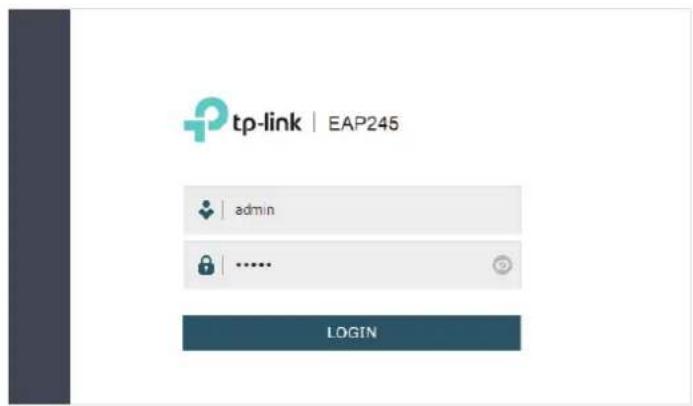
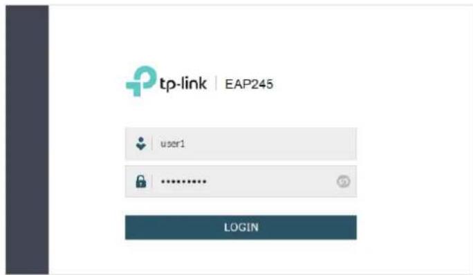
- Launch a web browser on the client device and enter http://tplinkeap.net in the address bar to load the login page of the EAP. Use admin for both of the username and password to log in.
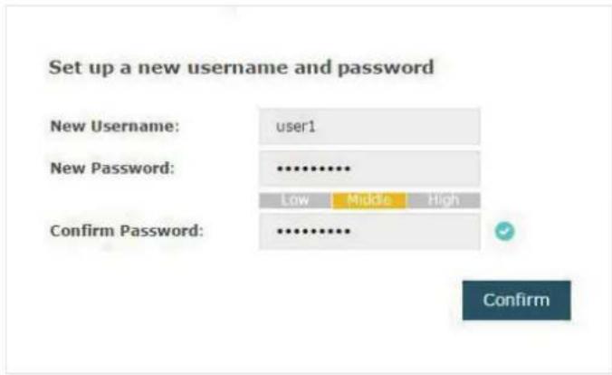
- In the pop-up window, configure a new username and a new password for your user account.
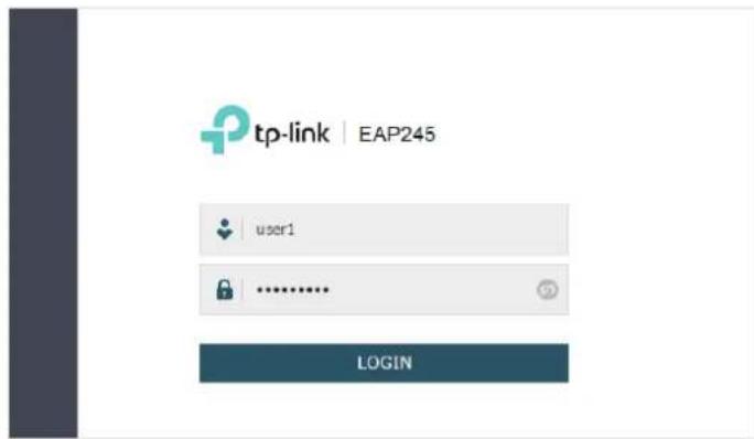
- Use the new username and password to log in.
Tips:
To facilitate access to the EAP via a wired device, you can set a static IP address for the EAP and remember it well or write it down. But make sure that this IP address is not being used in the same LAN. For detailed instructions about how to set a static IP address for the EAP, refer to Configure the IP Address of the EAP.
Log in via the IP Address of the EAP
To log in to the EAP through the Ethernet cable, you need to know the IP address of the EAP. Follow the steps below to log in via the IP address of the EAP:
- Get the IP address of the EAP. There are two methods.
- Log in to the router which acts as the DHCP server. In the DHCP client list, find the IP address of your EAP according to its MAC address. The MAC address can be found at the bottom of the EAP.
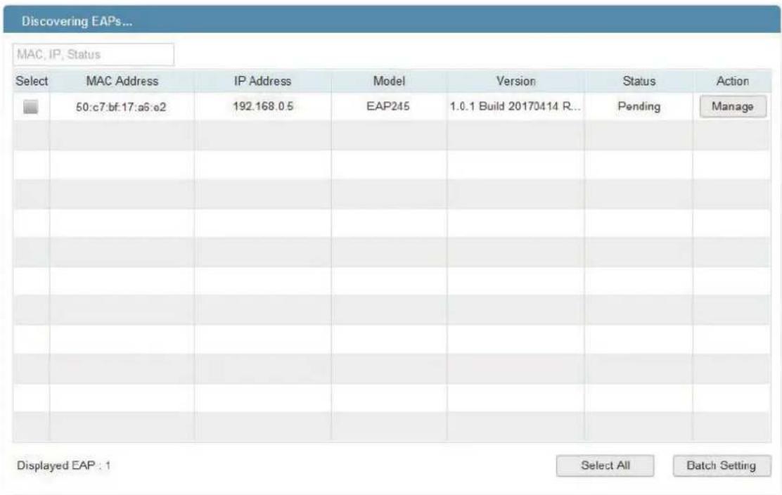
- Go to http://www.tp-link.com/en/download/EAP-Controller.html#EAP_Discovery_Tool to download EAP Discovery Utility. EAP Discovery Utility is a software that can scan all EAPs in the same network segment. Install and launch EAP Discovery Utility
on the PC, and find the IP address of the EAP. In the following figure, the IP address of the EAP is 192.168.0.5.
- Launch a web browser and enter 192.168.0.5 in the address bar to load the login page of the EAP. Use admin for both of the username and password to log in.

- In the pop-up window, configure a new username and a new password for your user account.

- Use the new username and password to log in.
Tips:
To facilitate access to the EAP via a wired device, you can set a static IP address for the EAP and remember it well or write it down. But make sure that this IP address is not being used in the same LAN. For detailed instructions about how to set a static IP address for the EAP, refer to Configure the IP Address of the EAP.
1.4 Edit the SSID
By default, the dual-band EAP has two default SSIDs named TP-LINK_2.4GHz_XXXXXX and TP-LINK_5GHz_XXXXXX on the 2.4GHz band and 5GHz band, and the single-band EAP has a default SSID named TP-LINK_2.4GHz_XXXXXX on the 2.4GHz band.
The default SSID has no password, so anyone can access the network without authentication. If your network is a private network, for security, we recommend that you change the SSID configuration immediately after login.
Follow the steps below to edit the default SSID:
- Go to the Wireless > Wireless Settings page. In the SSIDs section, click ☑ in the Modify column of the SSID entry.

tp-link
Access Point


Network
Wireless
Monitoring
Management
System
Wireless Settings
Portal
MAC Filtering
Scheduler
QoS
Rogue AP Detection
2.4GHz
5GHz
Wireless Basic Settings
2.4GHz Wireless Radio:
√ Enable
Wireless Mode:
802.11b/g/n mixed

Channel Width:
20/40MHz

Channel:
Auto

Tx Power(EIRP):
19
d8m(10-19)
Note:
The EIRP transmit power includes the antenna gain.
Save
SSIDs

Add
| ID | SSID | Wireless VLAN ID | SSID Broadcast | Security Mode | Portal | SSID Isolation | Modify |
| 1 | TP-LINK_2.4GHz_17A6E2 | 0 | Enable | None | Disable | Disable |
- The following page will appear. Change Security Mode from None to WEP, WPA-Enterprise or WPA-PSK. Configure the related parameters and click OK. We recommend that you choose WPA-PSK. For details, refer to Configure SSIDs.
SSIDs
| ID | SSID | Wireless VLAN ID | SSID Broadcast | Security Mode | Portal | SSID Isolation | Modify |
| 1 | TP-LINK_2.4GH2_17A6E2 | 0 | Enable | None | Disable | Disable | |
| SSID: | office_market | ||||||
| Wireless VLAN ID: | 0 | (0-4094, 0 is used to disable VLAN tagging.) | |||||
| SSID Broadcast: | Enable | ||||||
| Security Mode: | WPA-PSK | ||||||
| Version: | Auto WPA-PSK WPA2-PSK | ||||||
| Encryption: | Auto TKIP AES | ||||||
| Wireless Password: | 123456abc | ||||||
| Group Key Update Period: | 0 | seconds (30-8640000, 0 means no update.) | |||||
| Portal: | Enable | ||||||
| SSID Isolation: | Enable | ||||||
| Cancel | OK | ||||||
Tips:
- If needed, you can also create more new SSIDs. For detailed instructions about how to create new SSIDs, refer to Configure SSIDs.
- If your EAP is a dual-band EAP, remember to configure the SSID of the 5GHz band in the same way.
1.5 Configure and Manage the EAP
After all the steps above are completed, the legal wireless clients can enjoy the internet via the EAP. Additionally, you can configure the advanced functions of the EAP according to your need, and manage it conveniently on the web page.

On the top of the page, you can click to log out and click to open the technical support website.
There are five tabs: Network, Wireless, Monitoring, Management and System. The following table introduces what you can configure under each tab.
| Network You can configure the IP address of the EAP. |
| Wireless You can configure the wireless parameters and the advanced features, such as Portal, MAC Filtering, Scheduler, QoS and Rogue AP Detection. |
| Monitoring You can view the information of the EAP, SSIDs and clients. |
| Management You can manage the EAP using the management features, such as System Logs, Web Server, Management Access, Management VLAN and SNMP. |
| System You can configure the system parameters, including the login account and the system time. In addition, you can reboot and reset the EAP, backup and restore the configuration, and upgrade the EAP using the new firmware file. |
2 Configure the Network
This chapter introduces how to configure the network parameters and the advanced features of the EAP, including:
- Configure the IP Address of the EAP
- Configure the Wireless Parameters
- Configure Portal Authentication
- Configure MAC Filtering
- Configure Scheduler
- Configure QoS
- Configure Rogue AP Detection
2.1 Configure the IP Address of the EAP
The IP address of the EAP can be a dynamic IP address assigned by the DHCP server or a static IP address manually specified by yourself. By default, the EAP gets a dynamic IP address from the DHCP server. You can also specify a static IP address according to your needs.
Tips:
For detailed introduction about how to find the dynamic IP address of the EAP, refer to Log in via the IP Address of the EAP.
To configure the IP address of the EAP, go to the Network page.
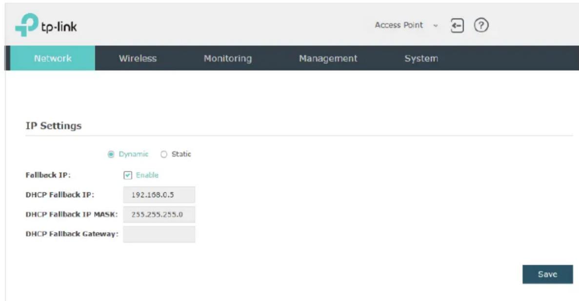
Follow the steps below to configure the IP address of the EAP:
- Choose your desired IP address mode: Dynamic or Static.
- Configure the related parameters according to your selection.
- Dynamic
If you choose Dynamic as the IP address mode, make sure that there is a reachable DHCP server on your network and the DHCP sever is properly configured to assign IP address and the other network parameters to the EAP.

For network stability, you can also configure the fallback IP parameters for the EAP:
| Fallback IP With the fallback IP configured, if the EAP fails to get an IP address from a DHCP server within 10 seconds, the fallback IP will work as the IP address of the EAP. After that, however, the EAP will keep trying to obtain an IP address from the DHCP server until it succeeds. | |
| DHCP Fallback IP | Specify a fallback IP address for the EAP. Make sure that this IP address is not being used by any other device in the same LAN. |
| DHCP Fallback IP MASK | Specify the network mask of the fallback IP. |
| DHCP Fallback Gateway | Specify the network gateway. |
- Static
If you choose Static as the IP address mode, you need to manually specify an IP address and the related network parameters for the EAP. Make sure that the specified IP address is not being used by any other device in the same LAN.
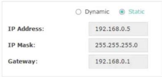
Configure the IP address and network parameters as the following table shows:
IP Address Specify a static IP address for the EAP.
IP Mask Specify the network mask.
Gateway Specify the network gateway.
- Click Save.
2.2 Configure the Wireless Parameters
To configure the wireless parameters, go to the Wireless > Wireless Settings page.
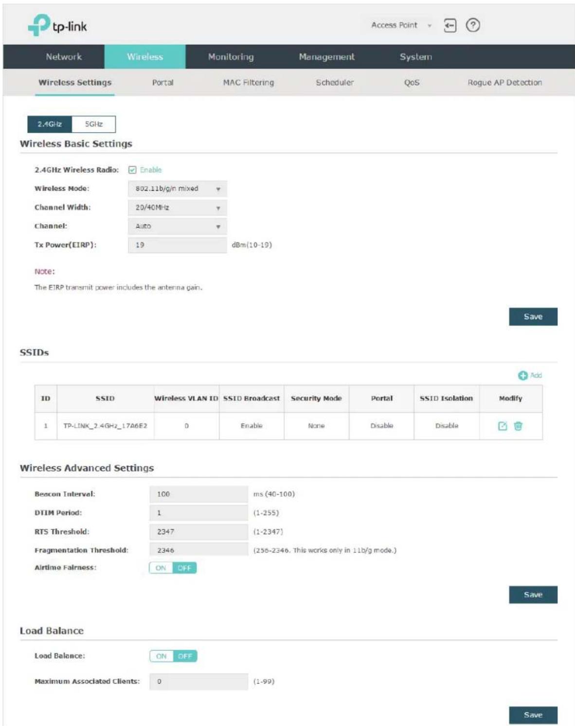
The following sections introduce these contents: Configure Basic Wireless Settings, Configure SSIDs, Cofigure Wireless Advanced Settings and Configure Load Balance.
Note:
- For a dual-band EAP, there are two bands: 2.4GHz and 5GHz. The wireless parameters are separately set on each band. You can click 2.4GHz to select a band and configure the wireless parameters on this band.
• The following figures take 2.4GHz as an example.
Configure Basic Wireless Settings
Proper wireless parameters can improve the quality of your wireless network. This section introduces how to configure the basic wireless parameters.
Wireless Basic Settings
5GHz Wireless Radio:

Wireless Mode:
802.11a/n/ac mixed

Channel Width:
20/40/80MHz

Channel Limit:

Note: In EU member states and EFTA countries, the operation in the frequency range 5150MHz-5350MHz is not allowed outdoors.
Channel:


Tx Power(EIRP):

dBm(7-30)
Note:
The EIRP transmit power includes the antenna gain.
Save
Follow the steps below to complete the basic wireless settings:
-
If your EAP is a dual-band device, click 2.4GHz 5GHz to choose a frequency band to be configured.
-
In the Wireless Basic Settings section, configure the following parameters:
2.4GHz Wireless Radio/5GHz Wireless Radio
Check the box to enable 2.4GHz/5GHz Wireless Radio. By default, it is enabled.
Only when this option is enabled will the wireless radio on 2.4GHz/5GHz band works.
Wireless Mode Select the protocol standard for the wireless network.
For 2.4GHz network, we recommend that you select 802.11b/g/n. In this way, clients supporting any one of these modes can access your wireless network.
For 5GHz network, we recommend that you select 802.11n/ac or 802.11a/n/ac. In this way, clients supporting any one of these modes can access your wireless network.
| Channel Width Select the channel width. | |
| According to IEEE 802.11n standard, using a higher bandwidth can increase wireless throughput. However, you may choose a lower bandwidth due to the following reasons:To increase the available number of channels within the limited total bandwidth.To avoid interference from overlapping channels occupied by other devices in the environment.Lower bandwidth can concentrate higher transmit power, increasing stability of wireless links over long distances. | |
| Channel Limit | Check the box to enable the Channel Limit function. With this function enabled, the wireless frequency 5150MHz~5350MHz will be disabled.This function can influence the available options in Channel.This feature is only available for 5GHz wireless configuration of EAP225-Outdoor. |
| Channel Select the channel used by the EAP. For example, 1/2412MHz means that the channel is 1 and the frequency is 2412MHz.By default, the channel is automatically selected, and we recommend that you keep the default setting. | |
| Tx Power (EIRP) Specify the transmit power value. | |
| If this value is set to be larger than the maximum transmit power that is allowed by the local regulation, the regulated maximum transmit power will be applied in the actual situation.Note: In most cases, it is unnecessary to use the maximum transmit power. Specifying a larger transmit power than needed may cause interference to the neighborhood. Also it consumes more power and reduces longevity of the device. | |
- Click Save.
Configure SSIDs
SSID (Service Set Identifier) is used as an identifier for a wireless LAN, and is commonly called as the "network name". Clients can find and access the wireless network through the SSID. For one EAP, you can build up to eight SSIDs per frequency band.
SSIDs

Follow the steps below to create an SSID on the EAP:
-
If your EAP is a dual-band device, click 2.4GHz 5GHz to choose a frequency band on which the new SSID will be created.
-
Click + Add to add a new SSID on the chosen band.
Tips:
If there are SSIDs already in the list, you can also click to edit the specific SSID.
- Configure the following required parameters for this SSID:
SSID Specify a name for the wireless network.
| Wireless VLAN ID | Set a VLAN ID for the wireless network. It supports maximum 8 VLANs per frequency band.With this feature, the EAP can work together with the switches supporting 802.1Q VLAN. The EAP adds different VLAN tags to the clients which are connected to the corresponding wireless network. The clients in different VLANs cannot directly communicate with each other.VLAN 0 means that the EAP does not add any VLAN tag to the clients which are connected to this wireless network.Note:Clients connected to the EAP via Ethernet cable do not belong to any VLAN. Thus wired client can communicate with all the wireless clients despite the VLAN settings. |
| SSID Broadcast With the option enabled, EAP will broadcast the SSID to the nearby hosts, so that those hosts can find the wireless network identified by this SSID. If this option is disabled, users must enter the SSID manually to connect to the EAP. | |
| Security Mode Select the security mode of the wireless network. There are four options:None:Clients can access the wireless network without authentication.WEPI/WPA-Enterprise/WPA-PSK: Clients need to pass the authentication before accessing the wireless network. For network security, we recommend that you encrypt your wireless network. The following sections will introduce how to configure these security modes. | |
| Portal With this option enabled, the Portal configuration will be applied to this wireless networkPortal provides authentication service for the clients who just need temporary access to the wireless network, such as the customers in a shopping mall or in a restaurant. Portal also provides a way for vendors and companies to put their advertisements on the authentication page. For detailed instructions about Portal, refer to Configure Portal Authentication. | |
| SSID Isolation With this option enabled, the devices connected to the same SSID cannot communicate with each other. | |
4. Click OK to create the SSID.
Following is the detailed instructions about how to configure WEP, WPA-Enterprise and WPA-PSK.
• WEP
WEP (Wired Equivalent Privacy) is a traditional encryption method. It has been proved that WEP has security flaws and can easily be cracked, so WEP cannot provide effective protection for wireless networks. Since WPA-PSK and WPA-Enterprise are much safer
than WEP, we recommend that you choose WPA-PSK or WPA-Enterprise if your clients also support them.
Note:
WEP is not supported in 802.11n mode or 802.11ac mode. If WEP is applied in 802.11n, 802.11 ac or 802.11n/ac mixed mode, the clients may not be able to access the wireless network. If WEP is applied in 802.11b/g/n mode (2.4GHz) or 802.11a/n (5GHz), the EAP may work at a low transmission rate.
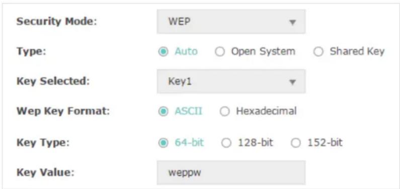
The following table detailedly introduces how to configure each item:
Type Select the authentication type for WEP.
Auto: The EAP can select Open System or Shared Key automatically based on the wireless capability and request of the clients.
Open System: Clients can pass the authentication and associate with the wireless network without password. However, correct password is necessary for data transmission.
Shared Key: Clients have to input the correct password to pass the authentication, otherwise the clients cannot associate with the wireless network or transmit data.
Key Selected Select one key to specify. You can configure four keys at most.
WEP Key Format Select ASCII or Hexadecimal as the WEP key format.
ASCII: With this format selected, the WEP key can be any combination of keyboard characters of the specified length.
Hexadecimal: With this format selected, the WEP key can be any combination of hexadecimal digits (0-9, a-f, A-F) with the specified length.
Key Type Select the WEP key length for encryption.
64Bit: Enter 10 hexadecimal digits or 5 ASCII characters.
128Bit: Enter 26 hexadecimal digits or 13 ASCII characters.
152Bit: Enter 32 hexadecimal digits or 16 ASCII characters.
Key Value Enter the WEP keys. The length and valid characters are determined by the key format and key type.
- WPA-Enterprise
WPA-Enterprise (Wi-Fi Protected Access-Enterprise) is a safer encryption method compared with WEP and WAP-PSK. It requires a RADIUS server to authenticate the clients via 802.1X and EAP (Extensible Authentication Protocol). WPA-Enterprise can generate different passwords for different clients, which ensures higher network security. But it also costs more to maintain the network, so it is more suitable for business networks.

The following table introduces how to configure each item:
Version Select the version of WPA-Enterprise.
Auto: The EAP will automatically choose the version used by each client device.
WPA/WPA2: They're two versions of WPA security mode. WPA2 is an update of WPA. Compared with WPA, WPA2 introduces AES algorithm and CCMP encryption. Theoretically, WPA2 is securer than WPA.
Encryption Select the Encryption type.
Auto: The default setting is Auto and the EAP will select TKIP or AES automatically based on the client device's request.
TKIP: Temporal Key Integrity Protocol. TKIP is not supported in 802.11n mode, 802.11ac mode or 802.11n/ac mixed mode. If TKIP is applied in 802.11n, 802.11 ac or 802.11n/ac mixed mode, the clients may not be able to access the wireless network. If TKIP is applied in 11b/g/n mode (2.4GHz) or 11a/n mode(5GHz), the device may work at a low transmission rate.
AES: Advanced Encryption Standard. It is securer than TKIP.
RADIUS Server IP Enter the IP address of the Radius Server.
RADIUS Port Enter the port number of the Radius Server.
RADIUS Password Enter the shared secret key of the Radius server.
Group Key Update Period
Specify an update period of the encryption key. The update period instructs how often the EAP should change the encryption key. 0 means that the encryption key does not change at anytime.
- WPA-PSK
WPA-PSK (Wi-Fi Protected Access-PSK) is based on a pre-shared key. It is characterized by high safety and simple settings, so it is mostly used by common households and small businesses.
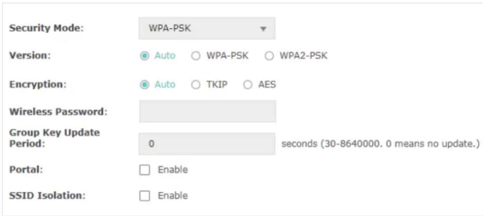
The following table introduces how to configure each item:
Version Select the version of WPA-Enterprise.
Auto: The EAP will automatically choose the version used by each client device.
WPA-PSK/WPA2-PSK: They're two versions of WPA-PSK security mode. WPA2-PSK is an update of WPA-PSK. Compared with WPA, Theoretically, WPA2 is securer than WPA.
Encryption Select the Encryption type.
Auto: The default setting is Auto and the EAP will select TKIP or AES automatically based on the client device's request.
TKIP: Temporal Key Integrity Protocol. TKIP is not supported in 802.11n mode, 802.11ac mode or 802.11n/ac mixed mode. If TKIP is applied in 802.11n, 802.11 ac or 802.11n/ac mixed mode, the clients may not be able to access the wireless network. If TKIP is applied in 11b/g/n mode (2.4GHz) or 11a/n mode(5GHz), the device may work at a low transmission rate.
AES: Advanced Encryption Standard. It is securer than TKIP.
| Wireless Password | Configure the wireless password with ASCII or Hexadecimal characters.For ASCII, the length should be between 8 and 63 and the valid characters contain numbers, letters (case-sensitive) and common punctuations.For Hexadecimal, the length should be between 8 and 64, and the valid characters contain: 0-9, a-f, A-F. |
| Group Key Update Period | Specify an update period of the encryption key. The update period instructs how often the EAP should change the encryption key. 0 means that the encryption key does not change at anytime. |
Cofigure Wireless Advanced Settings
Configure the advanced wireless parameters of the EAP and click Save.
Wireless Advanced Settings
Beacon Interval:
DTIM Period:
RTS Threshold:
Fragmentation Threshold:
Airtime Fairness:
100
1
2347
2346
ON
OFF
ms (40-100)
(1-255)
(1-2347)
(256-2346. This works only in 11b/g mode.)
Save
The following table introduces how to configure each item:
Beacon Interval Beacons are transmitted periodically by the EAP device to announce the presence of a wireless network for the clients. Beacon Interval determines the time interval of the beacons sent by the EAP device.
You can specify a value between 40 and 100ms. The default is 100ms.
DTIM Period The DTIM (Delivery Traffic Indication Message) is contained in some Beacon frames. It indicates whether the EAP device has buffered data for client devices. The DTIM Period indicates how often the clients served by this EAP device should check for buffered data still on the EAP device awaiting pickup.
You can specify the value between 1-255 Beacon Intervals. The default value is 1, indicating that clients check for buffered data at every beacon. An excessive DTIM interval may reduce the performance of multicast applications, so we recommend you keep the default value.
| RTS Threshold RTS/CTS (Request to Send/Clear to Send) is used to improve the data transmission efficiency of the network with hidden nodes, especially when there are lots of large packets to be transmitted.When the size of a data packet is larger than theRTS Threshold, the RTS/CTS mechanism will be activated. With this mechanism activated, before sending a data packet, the client will send an RTS packet to the EAP to request data transmitting. And then the EAP will send CTS packet to inform other clients to delay their data transmitting. In this way, packet collisions can be avoided.For a busy network with hidden nodes, a low threshold value will help reduce interference and packet collisions. But for a not-so-busy network, a too low threshold value will cause bandwidth wasting and reduce the data throughput. The recommended and default value is 2347 bytes. | |
| Fragmentation Threshold | The fragmentation function can limit the size of packets transmitted over the network. If the size of a packet exceeds theFragmentation Threshold, the fragmentation function is activated and the packet will be fragmented into several packets.Fragmentation helps improve network performance if properly configured. However, a too low fragmentation threshold may result in poor wireless performance caused by the extra work of dividing up and reassembling of frames and increased message traffic. The recommended and default value is 2346 bytes. |
| Airtime Fairness EAP225_V3, EAP225-Outdoor_V1, EAP245_V3, EAP320 and EAP330 support this feature.With this option enabled, each client connected to the EAP can get the same amount of time to transmit data, avoiding low-data-rate clients to occupy too much network bandwidth.Compared with the relatively new client devices, some legacy client devices support slower wireless rate. If they communicate with the same EAP, the slower clients take more time to transmit and receive data compared with the faster clients. As a result, the overall wireless throughput of the network decreases. So under such circumstance, we recommend that you enable this feature to ensure the data transmission time for the faster clients. In this way, the network overall throughput can be improved.For EAP225_V3 and EAP225-Outdoor_V1, with this option enabled, at most 50 wireless clients can connect to the EAP in 2.4GHz band. | |
Configure Load Balance
With the Load Balance feature, you can limit the maximum number of clients who can access the EAP. In this way, you can achieve rational use of network resources.

Follow the steps below to configure Load Balance:
- Click 2.4GHz 5GHz to choose a frequency band on which the load balance feature will take effect.
- In the Load Balance section, click ON OFF to enable this feature. The ON button with cyan background color indicates this feature is enabled.
- Specify the maximum number of clients who can connect to the EAP at the same time. While the number of connected clients has reached the limit and there are more clients requesting to access the network, the EAP will disconnect those with weaker signals.
- Click Save.
2.3 Configure Portal Authentication
Portal authentication provides authentication service to the clients that only need temporary access to the wireless network, such as the customers in a restaurant or in a supermarket. To access the network, these clients need to enter the authentication login page and use the correct login information to pass the authentication. In addition, you can customize the authentication login page and specify a URL which the authenticated clients will be redirected to.
In this module, you can also configure Free Authentication Policy, which allows the specific clients to access the specific network resources without authentication.
To configure portal authentication, go to the Wireless > Portal page.
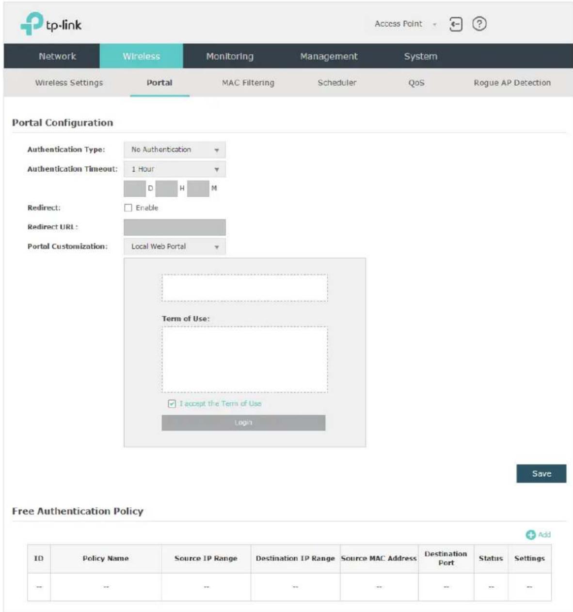
Configure Portal
Three portal authentication types are available: No Authentication, Local Password and External Radius Server. The following sections introduce how to configure each authentication type.
- No Authentication
With this authentication type configured, clients can pass the authentication and access the network without providing any login information. They only need to accept the term of use on the authentication page.
Portal Configuration
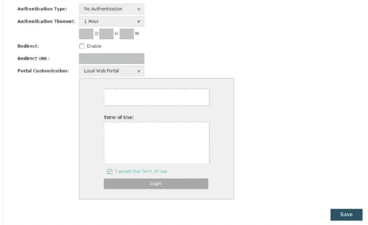
Follow the steps below to configure No Authentication as the portal authentication type:
-
Select No Authentication as the authentication type.
-
Configure the relevant parameters as the following table shows:
| AuthenticationTimeout | Specify the value of authentication timeout.A client's authentication will expire after the authentication timeout and the client needs to log in to the authentication page again to access the network.Options include 1 Hour, 8 Hours, 24 Hours, 7 Days, and Custom. With Custom selected, you can customize the time in days, hours, and minutes. |
| Redirect With this function configured, the newly authenticated client will be redirected to the specific URL. | |
| Redirect URL | With Redirect enabled, you also need to enter the URL in this field. The newly authenticated client will be redirected to this URL. |
Portal Customization
Configure the authentication page. Local Web Portal is the only available option in this authentication type. Enter the title and term of use in the two boxes.
The EAP uses its built-in web server to provide this authentication page for clients. To pass the authentication, clients only need to check the box of I accept the Term of Use and click the Login button.
-
Click Save.
-
Go to the Wireless > Wireless Settings page and enable the Portal option for the specific SSID. Then the portal authentication feature will take effect on this SSID.
Portal:

Enable
- Local Password
With this authentication type configured, clients are required to provide the correct password to pass the authentication.

Follow the steps below to configure Local Password as the portal authentication type:
- Select Local Password as the authentication type.
- Configure the relevant parameters as the following table shows:
| AuthenticationTimeout | Specify the value of authentication timeout.A client's authentication will expire after the authentication timeout and the client needs to log in to the authentication page again to access the network.Options include 1 Hour, 8 Hours, 24 Hours, 7 Days, and Custom. With Custom selected, you can customize the time in days, hours, and minutes. |
| Password Specify a password for authentication. | |
| Redirect With this function configured, the newly authenticated client will be redirected to the specific URL. | |
| Redirect URL | With Redirect enabled, you also need to enter the URL in this field. The newly authenticated client will be redirected to this URL. |
| PortalCustomization | Configure the authentication page. Local Web Portal is the only available option is this authentication type. Enter the title and term of use in the two boxes.The EAP uses its built-in web server to provide this authentication page for clients. To pass the authentication, clients need to provide the correct password in the Password field, check the box of I accept the Term of Use and click the Login button. |
- Click Save.
- Go to the Wireless > Wireless Settings page and enable the Portal option for the specific SSID. Then the portal authentication feature will take effect on this SSID.
Portal:

Enable
• External Radius Server
If you have a RADIUS server on the network to authenticate the clients, you can select External Radius Server. Clients need to provide the correct login information to pass the authentication.
Portal Configuration
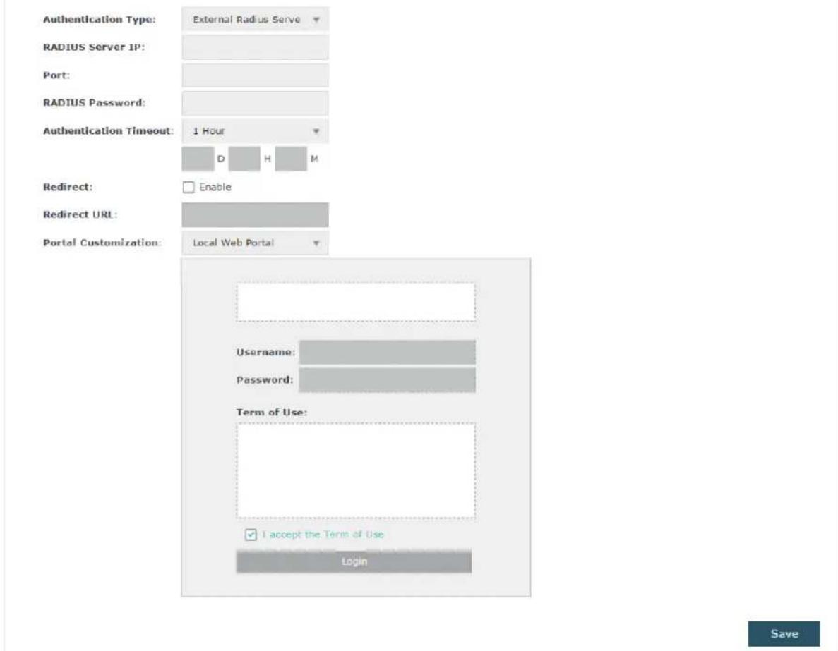
Follow the steps below to configure External Radius Server as the portal authentication type:
- Build a Radius server on the network and make sure that it is reachable by the EAP.
- Go to the Portal configuration page on the EAP. Select External Radius Server as the authentication type.
- Configure the relevant parameters as the following table shows:
RADIUS Server IP Enter the IP address of RADIUS server.
Port Enter the port of the RADIUS server.
RADIUS
Password
Enter the password of the RADIUS server.
| AuthenticationTimeout | Specify the value of authentication timeout.A client's authentication will expire after the authentication timeout and the client needs to log in to the authentication page again to access the network.Options include 1 Hour, 8 Hours, 24 Hours, 7 Days, and Custom. With Custom selected, you can customize the time in days, hours, and minutes. |
| Redirect With this function configured, the newly authenticated client will be redirected to the specific URL. | |
| Redirect URL | With Redirect enabled, you also need to enter the URL in this field. The newly authenticated client will be redirected to this URL. |
| PortalCustomization | Configure the authentication page. There are two options: Local Web Portal and External Web Portal.Local Web PortalEnter the title and term of use in the two boxes. The EAP uses its built-in web server to provide this authentication page for clients. To pass the authentication, clients need to provide the correct username and password in the Username and Password fields, check the box of I accept the Term of Use and click the Login button.External Web PortalWith External Web Portal configured, the authentication page will be provided by the web portal server built on the network. To configure External Web Portal, you need to complete the following configurations:Build an external web portal server on your network and make sure that it is reachable by the EAP.On this configuration page, enter the URL of the authentication page provided by the external portal server. |
| Portal Customization: External Web PortalExternal Web PortalURL:3. Add the external web portal server to the Free Authentication Policy list. In this way, clients can access the web portal server before authenticated. For details about how to configure Free Authentication Policy, refer to Configure Free Authentication Policy. | |
-
Click Save.
-
Go to the Wireless > Wireless Settings page and enable the Portal option for the specific SSID. Then the portal authentication feature will take effect on this SSID.

Configure Free Authentication Policy
Free Authentication Policy allows some specific clients to access the specific network resources without authentication. For example, you can set a free authentication policy to allow clients to visit the external web portal server before authenticated. In this way, the clients can visit the login page provided by the web portal server and then pass the subsequent authentication process.
Free Authentication Policy
| ID | Policy Name | Source IP Range | Destination IP Range | Source MAC Address | Destination Port | Status | Settings |
| -- | -- | -- | -- | -- | -- | -- | -- |
Follow the steps below to add free authentication policy.
- In the Free Authentication Policy section, click + Add to load the following page.
| ID | Policy Name | Source IP Range | Destination IP Range | Source MAC Address | Destination Port | Status | Settings |
| - | - | - | - | - | - | - | - |
| Policy Name: | |||||||
| Source IP Range: | 0.0,0.0 | / | (Optional) | ||||
| Destination IP Range: | 0.0,0.0 | / | (Optional) | ||||
| Source MAC Address: | 00-00-00-00-00-00 | (Optional) | |||||
| Destination Port: | (Optional) | ||||||
| Status: | □ Enable | ||||||
| Cancel | OK | ||||||
- Configure the following parameters. When all the configured conditions are met, the client can access the network without authentication.
| Policy Name Specify a name for the policy. | |
| Source IP Range Specify an IP range with the subnet and mask length. The clients in this IP range can access the network without authentication.Leaving the field empty means that clients with any IP address can access the specific resources. | |
| Destination IP Range | Specify an IP range with the subnet and mask length. The devices in this IP range can be accessed by the clients without authentication.Leaving the field empty means that all devices in the LAN can be accessed by the specific clients. |
| Source MAC Address | Specify the MAC address of the client, who can access the specific resources without authentication.Leaving the field empty means that clients with any MAC address can access the specific resources. |
| Destination Port Specify the port number of the service. When using this service, the clients can access the specific resources without authentication.Leaving the field empty means that clients can access the specific resources no matter what service they are using. | |
| Status Check the box to enable the policy. | |
Tips:
When External Web Portal is configured in the portal configuration, you should set the IP address and subnet mask of the external web server as the Destination IP Range. As for Source IP Range, Source MAC Address and Destination Port, you can simply keep them as empty or configure them according to your actual needs.
- Click OK to add the policy.
2.4 Configure MAC Filtering
MAC Filtering is used to allow or block the clients with specific MAC addresses to access the network. With this feature you can effectively control clients' access to the wireless network according to your needs.
To configure MAC Filtering, go to the Wireless > MAC Filtering page.

Follow the steps below to configure MAC Filtering on this page:
- In the Settings section, check the box to enable MAC Filtering, and click Save.
Settings
Enable MAC Filtering

- In the Station MAC Group section, click + Create Groups and the following page will appear.
Station MAC Group
| MAC Group Name | Modify | ID | MAC Address | Modify | |
| - | - | → | - | - | - |
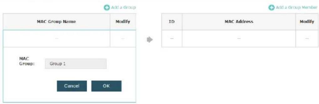
1) Click + Add a Group and specify a name for the MAC group to be created. Click OK. You can create up to eight MAC groups.
Station MAC Group
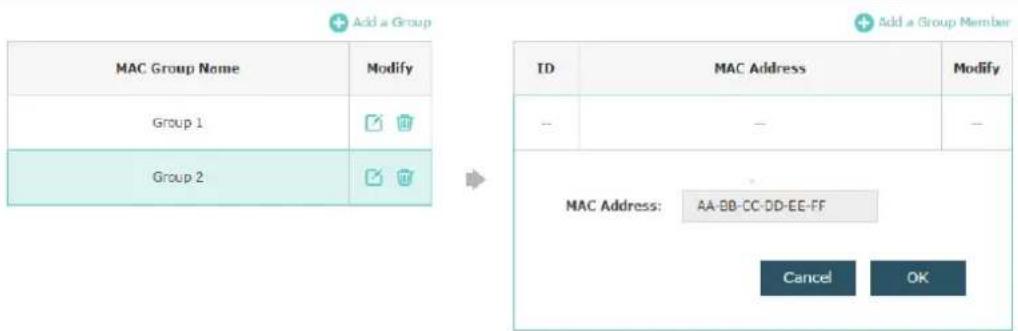
2) Select a MAC group in the group list (the color of the selected one will change to blue). Click Add a Group Member to add group members to the MAC group. Specify the MAC address of the host and click OK. In the same way, you can add more MAC addresses to the selected MAC group.
Station MAC Group
- In the MAC Filtering Association section, configure the filtering rule. For each SSID, you can select a MAC group in the MAC Group Name column and select the filtering rule (Allow/Deny) in the Action column. Click Save.
For example, the following configuration means that the hosts in Group 2 are denied to access the SSID TP-LINK_2.4GHz_17A6E2 on the 2.4GHz band and allowed to access the SSID TP-LINK_5GHz_17A6E3 on the 5GHz band.
MAC Filtering Association
| ID | SSID | Band | MAC Group Name | Action |
| 1 | TP-LINK_2.4GHz_17A6E2 | 2.4GHz | Group 2 | Deny |
| 2 | TP-LINK_SGHz_17A6E3 | 5GHz | Group 2 | Allow |
Note:
Deny: Block access from the stations in the MAC Group list.
Allow: Only allow access from the stations in the MAC Group list.
Save
2.5 Configure Scheduler
With the Scheduler feature, the EAP or its wireless network can automatically turn on or off at the time you set. For example, you can schedule the radio to operate only during the office working time to reduce power consumption.
To configure Scheduler, go to the Wireless > Scheduler page.
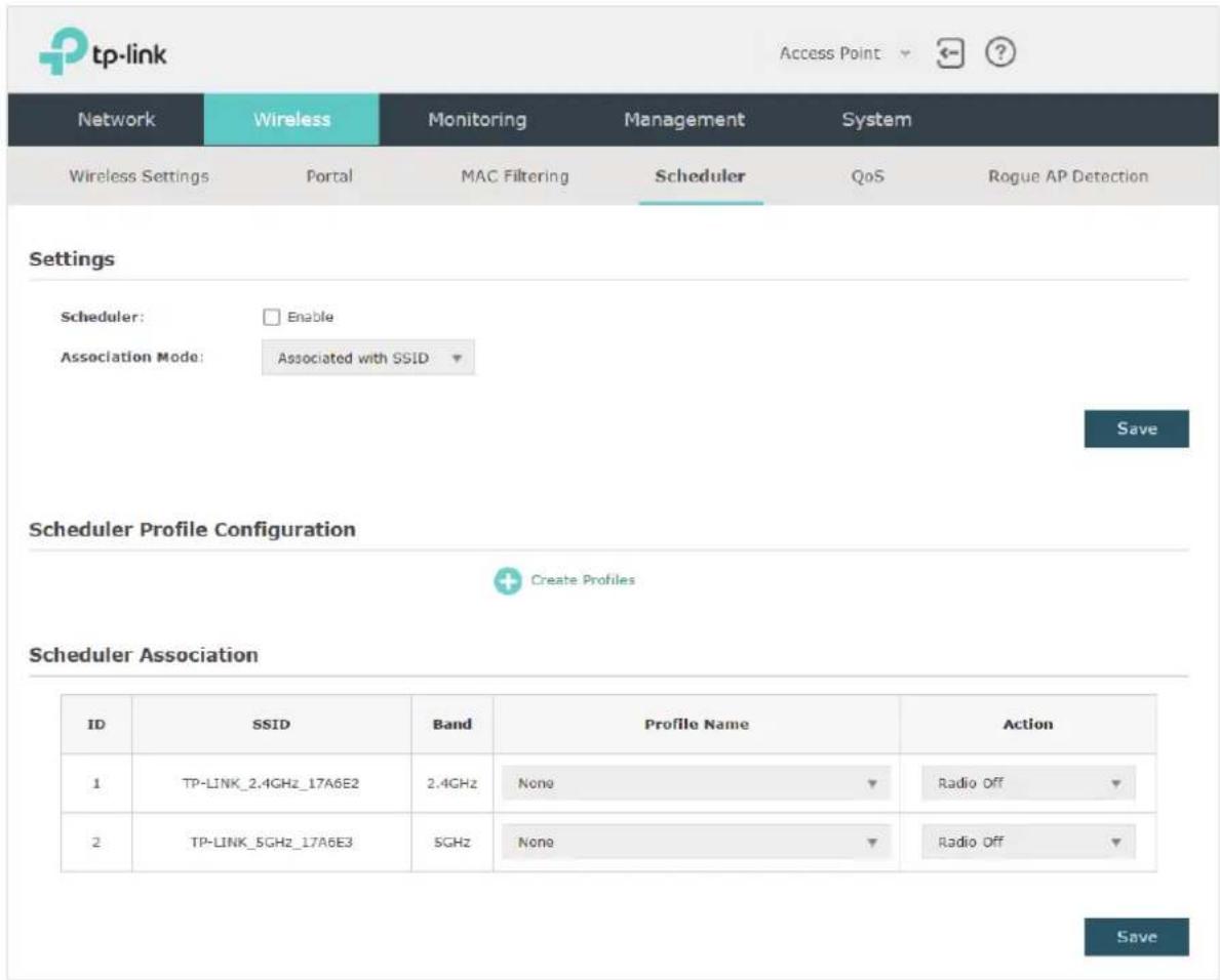
Follow the steps below to configure Scheduler on this page:
- In the Settings section, check the box to enable Scheduler and select the Association Mode. There are two modes: Associated with SSID (the scheduler profile will be applied to the specific SSID) and Associated with AP (the profile will be applied to all SSIDs on the EAP). Then click Save.

- In the Scheduler Profile Configuration section, click + Create Profiles and the following page will appear.

1) Click + Add a Profile and specify a name for the profile to be created. Click OK. You can create up to eight profiles.

2) Select a profile in the list (the color of the selected one will change to blue). Click
Add an item to add time range items to the profile. Specify the Day, Start Time and End Time of the time range, and click OK.

Tips:
You can add up to eight time range items for one profile. If there are several time range items in one profile, the time range of this profile is the sum of all of these time ranges.
- In the Scheduler Association section, configure the scheduler rule. There are two association modes: Association with SSID and Association with AP. The following sections introduce how to configure each mode.
■ Association with SSID
If you select Association with SSID in step 1, the Scheduler Association table will display all the SSIDs on the EAP. For each SSID, you can select a profile in the Profile Name column and select the scheduler rule (Radio On/Radio Off) in the Action column. Then click Save.
For example, the following configuration means that during the time range defined in Profile2, the radio of SSID TP-LINK_2.4GHz_17A6E2 is on and the radio of SSID TPLINK_5GHz_17A6E3 is off.
| ID | SSID | Band | Profile Name | Action |
| 1 | TP-LINK_2.4GHz_17A6E2 | 2.4GHz | Profile 2 | Radio On |
| 2 | TP-LINK_5GHz_17A6E3 | 5GHz | Profile 2 | Radio Off |
■ Association with AP
If you select Association with AP in step 1, the Scheduler Association table will display the name and MAC address of the EAP. Select a profile in the Profile Name column and select the scheduler rule (Radio On/Radio Off) in the Action column. Then click Save.
For example, the following configuration means that during the time range defined in Profile2, the radio of all SSIDs on the EAP is on.
| ID | AP | AP MAC | Profile Name | Action |
| 1 | EAP245-50-c7-bf-17-a6-e2 | 50-C7-BF-17-A6-E2 | Profile 2 | Radio On |
2.6 Configure QoS
Quality of service (QoS) is used to optimize the throughput and performance of the EAP when handling differentiated wireless traffic, such as Voice-over-IP (VoIP), other types of audio, video, streaming media, and traditional IP data.
In QoS configuration, you should set parameters on the transmission queues for different types of wireless traffic and specify minimum and maximum wait time for data transmission. In normal use, we recommend that you keep the default values.
To configure QoS, go to the Wireless > QoS page.

Follow the steps below to configure QoS on this page:
- Click 2.4GHz 5GHz to choose a frequency band to be configured.
- Check the box to enable Wi-Fi Multimedia (WMM). With WMM enabled, the EAP uses the QoS function to guarantee the high priority of the transmission of audio and video packets.

Note:
If 802.11n only mode is selected in 2.4GHz (or 802.11n only, 802.11ac only, or 802.11 n/ac mixed mode selected in 5GHz), the WMM should be enabled. If WMM is disabled, the 802.11n only mode cannot be selected in 2.4GHz (or 802.11n only, 802.11ac only, or 802.11 n/ac mixed mode in 5GHz).
- In the AP EDCA Parameters section, configure the AP EDCA ((Enhanced Distributed Channel Access) parameters. AP EDCA parameters affect traffic flowing from the EAP device to the client station. The following table detailedly explains these parameters.
AP EDCA Parameters
| Queue | Arbitration Inter-Frame Spacing | Minimum Contention Window | Maximum Contention Window | Maximum Burst |
| Data 0 (Voice) | 1 | 3▼ | 7▼ | 1504 |
| Data 1 (Video) | 1 | 7▼ | 15▼ | 3008 |
| Data 2 (Best Effort) | 3 | 15▼ | 63▼ | 0 |
| Data 3 (Background) | 7 | 15▼ | 1023▼ | 0 |
The following table detailedly explains these parameters:
Queue Displays the transmission queue. By default, the priority from high to
low is Data 0, Data 1, Data 2, and Data 3. The priority may be changed if you reset the EDCA parameters.
Data 0 (Voice): Highest priority queue, minimum delay. Timesensitive data such as VoIP and streaming media are automatically sent to this queue.
Data 1 (Video): High priority queue, minimum delay. Time-sensitive video data is automatically sent to this queue.
Data 2 (Best Effort): Medium priority queue, medium throughput and delay. Most traditional IP data is sent to this queue.
Data 3 (Background): Lowest priority queue, high throughput. Bulk data that requires maximum throughput and is not time-sensitive is sent to this queue (FTP data, for example).
Arbitration Inter- Frame Space
A wait time for data frames. The wait time is measured in slots. Valid values are from 0 to 15.
Minimum Contention Window
A list to the algorithm that determines the initial random backoff wait time (window) for retry of a transmission.
This value cannot be higher than the value of Maximum Contention Window.
Maximum Contention Window
The upper limit (in milliseconds) for the doubling of the random backoff value. This doubling continues until either the data frame is sent or the Maximum Contention Window size is reached.
This value must be higher than the value of Minimum Contention Window.
Maximum Burst Maximum Burst specifies the maximum burst length allowed for packet bursts on the wireless network. A packet burst is a collection of multiple frames transmitted without header information. The decreased overhead results in higher throughput and better performance.
- In the Station EDCA Parameters section, configure the station EDCA (Enhanced Distributed Channel Access) parameters. Station EDCA parameters affect traffic flowing from the client station to the EAP device.
Station EDCA Parameters
| Queue | Arbitration Inter-Frame Spacing | Minimum Contention Window | Maximum Contention Window | TXOP Limit |
| Data 0 (Voice) | 2 | 3▼ | 7▼ | 1504 |
| Data 1 (Video) | 2 | 7▼ | 15▼ | 3008 |
| Data 2 (Best Effort) | 3 | 15▼ | 1023▼ | 0 |
| Data 3 (Background) | 7 | 15▼ | 1023▼ | 0 |
The following table detailedly explains these parameters:
Queue Displays the transmission queue. By default, the priority from high to low is Data 0, Data 1, Data 2, and Data 3. The priority may be changed if you reset the EDCA parameters.
Data 0 (Voice): Highest priority queue, minimum delay. Timesensitive data such as VoIP and streaming media are automatically sent to this queue.
Data 1 (Video): High priority queue, minimum delay. Time-sensitive video data is automatically sent to this queue.
Data 2 (Best Effort): Medium priority queue, medium throughput and delay. Most traditional IP data is sent to this queue.
Data 3 (Background): Lowest priority queue, high throughput. Bulk data that requires maximum throughput and is not time-sensitive is sent to this queue (FTP data, for example).
Arbitration Inter-Frame Space A wait time for data frames. The wait time is measured in slots. Valid values are from 0 to 15.
Minimum A list to the algorithm that determines the initial random backoff wait time (window) for retry of a transmission.
This value cannot be higher than the value of Maximum Contention Window.
| Maximum Contention Window | The upper limit (in milliseconds) for the doubling of the random backoff value. This doubling continues until either the data frame is sent or the Maximum Contention Window size is reached.This value must be higher than the value of Minimum Contention Window. |
| TXOP Limit The TXOP Limit is a station EDCA parameter and only applies to traffic flowing from the client station to the EAP device.The Transmission Opportunity (TXOP) is an interval of time, in milliseconds, when a WME (Wireless Multimedia Extensions) client station has the right to initiate transmissions onto the wireless medium (WM) towards the EAP device. The valid values are multiples of 32 between 0 and 8192. | |
- Choose whether to enable the following two options according to your need.

The following table detailedly explains these options:
| No Acknowledgement With this option enabled, the EAP would not acknowledge frames with QosNoAck. No Acknowledgement is recommended if VoIP phones access the network through the EAP device. | |
| Unscheduled Automatic Power Save Delivery | As a power management method, it can greatly improve the energy-saving capacity of clients. |
- Click Save.
2.7 Configure Rogue AP Detection
A Rogue AP is an access point that is installed on a secure network without explicit authorization from the network administrator. With Rogue AP Detection, the EAP can scan all channels to detect the nearby APs and display the detected APs in the Detected Rogue AP list. If the specific AP is known as safe, you can move it to the Trusted APs list. Also, you can backup and import the Trusted AP list as needed.
Note:
The Rogue AP Detection feature is only used for collecting information of the nearby wireless network and does not impact the detected APs, no matter what operations you have executed in this feature.
To configure Rogue AP Detection, go to the Wireless > Rogue AP Detection page.

Detect Rogue APs & Move the Rogue APs to the Trusted AP List
Follow the steps below to detect the nearby APs and move the trusted ones to the Trusted AP list.
- In the Settings section, check the box to enable Rogue AP Detection. Click Save.
Settings
Rogue AP Detection:

- In the Detected Rogue AP List section, click

Scan
- Wait for a few seconds without any operation. After detection is finished, the detected APs will be displayed in the list.
Detected Rogue AP List
| Action | MAC | SSID | Band | Channel | Security | Beacon Interval | Signal |
| Known | 00:0A:EB:13:7A:FF | TP-LINK_7AFF | 2.4 | 1 | ON | 100 | |
| Known | 00:36:76:26:1F:F2 | 36 | 2.4 | 1 | ON | 100 | |
| Known | 14:75:90:37:D2:EC | quxy-wifi | 2.4 | 6 | ON | 100 | |
| Known | 18:A6:F7:20:02:E0 | AD?200 | 2.4 | 1 | ON | 100 | |
| Known | 18:CF:SE:00:93:16 | 123 | 2.4 | 1 | ON | 100 | |
| Known | 1C:FA:68:58:B2:12 | pingan | 2.4 | 6 | ON | 100 | |
| Known | 20:76:93:31:47:0C | UniIC-2.4 | 2.4 | 12 | ON | 100 | |
| Known | 20:DC:E6:55:5A:20 | pingan_web | 2.4 | 6 | ON | 100 | |
| Known | 2C:D0:SA:EC:2E:36 | LieBaoWiFi860 | 2.4 | 11 | ON | 100 | |
| Known | 34:96:72:D4:29:E7 | ZYD | 2.4 | 1 | ON | 100 |
1 2 3 4 5 6 7
The following table introduces the displayed information of the APs:
MAC Displays the MAC address of the AP.
SSID Displays the SSID of the AP.
Band Displays the frequency band the AP is working on.
Channel Displays the channel the AP is using.
Security Displays whether the security mode is enabled on the AP.
Beacon Interval Displays the Beacon Interval value of the EAP.
Beacon frames are sent periodically by the AP to announce to the stations the presence of a wireless network. Beacon Interval determines the time interval of the beacon frames sent by the AP device.
Signal Displays the signal strength of the AP.
-
To move the specific AP to the Trusted AP list, click Known in the Action column. For example, we move the first two APs in the above Detected Rogue AP list to the Trusted AP list.
-
View the trusted APs in the Trusted AP List section. To move the specific AP back to the Rogue AP list, you can click Unknown in the Action column.
Trusted AP List
| Action | MAC | SSID | Band | Channel | Security |
| Unknown | 00:0A:EB:13:7A:FF | TP-LINK_7AFF | 2.4 | 1 | ON |
| Unknown | 00:36:76:26:1F:F2 | 36 | 2.4 | 1 | ON |
Manage the Trusted AP List
You can download the trusted AP list from your local host to the EAP or backup the current Trusted AP list to your local host.
• Download the Trusted AP List From the Host
You can import a trusted AP list which records the MAC addresses of the trusted APs. The AP whose MAC address is in the list will not be detected as a rogue AP.
Download/Backup Trusted AP List
Save Action:
Download (PC to AP)
Backup (AP to PC)
Source File Name:

Browse
File Management:
Replace
Merge
Save
Follow the steps below to import a trusted AP list to the EAP:
-
Acquire the trusted AP list. There are two ways:
-
Backup the list from a EAP. For details, refer to Backup the Trusted AP List to the Host.
-
Manually create a trusted AP list. Create a txt. file, input the MAC addresses of the trusted APs in the format XX:XX:XX:XX:XX and use the Space key to separate each MAC address. Save the file as a cfg file.
-
On this page, check the box to choose Download (PC to AP).
- Click Browse and select the trusted AP list from your local host.
-
Select the file management mode. Two modes are available: Replace and Merge. Replace means that the current trusted AP list will be replaced by the one you import. Merge means that the APs in the imported list will be added to the current list with the original APs remained.
-
Click Save to import the trusted AP list.
• Backup the Trusted AP List to the Host
You can backup the current trusted AP list and save the backup file to the local host.
Download/Backup Trusted AP List
Save Action:
○ Download (PC to AP)
Backup (AP to PC)
Save
Follow the steps below to backup the current trusted AP list:
- On this page, check the box to choose Backup (AP to PC).
- Click Save and the current trusted AP list will be downloaded to your local host as a cfg file.
3 Monitor the Network
This chapter introduces how to monitor the running status and statistics of the wireless network, including:
- Monitor the EAP
• Monitor the SSIDs
• Monitor the Clients
3.1 Monitor the EAP
You can view the information of the EAP, including device information, wireless settings, LAN information, client information, LAN traffic and radio traffic.
To monitor the EAP information, go to the Monitoring > AP page.
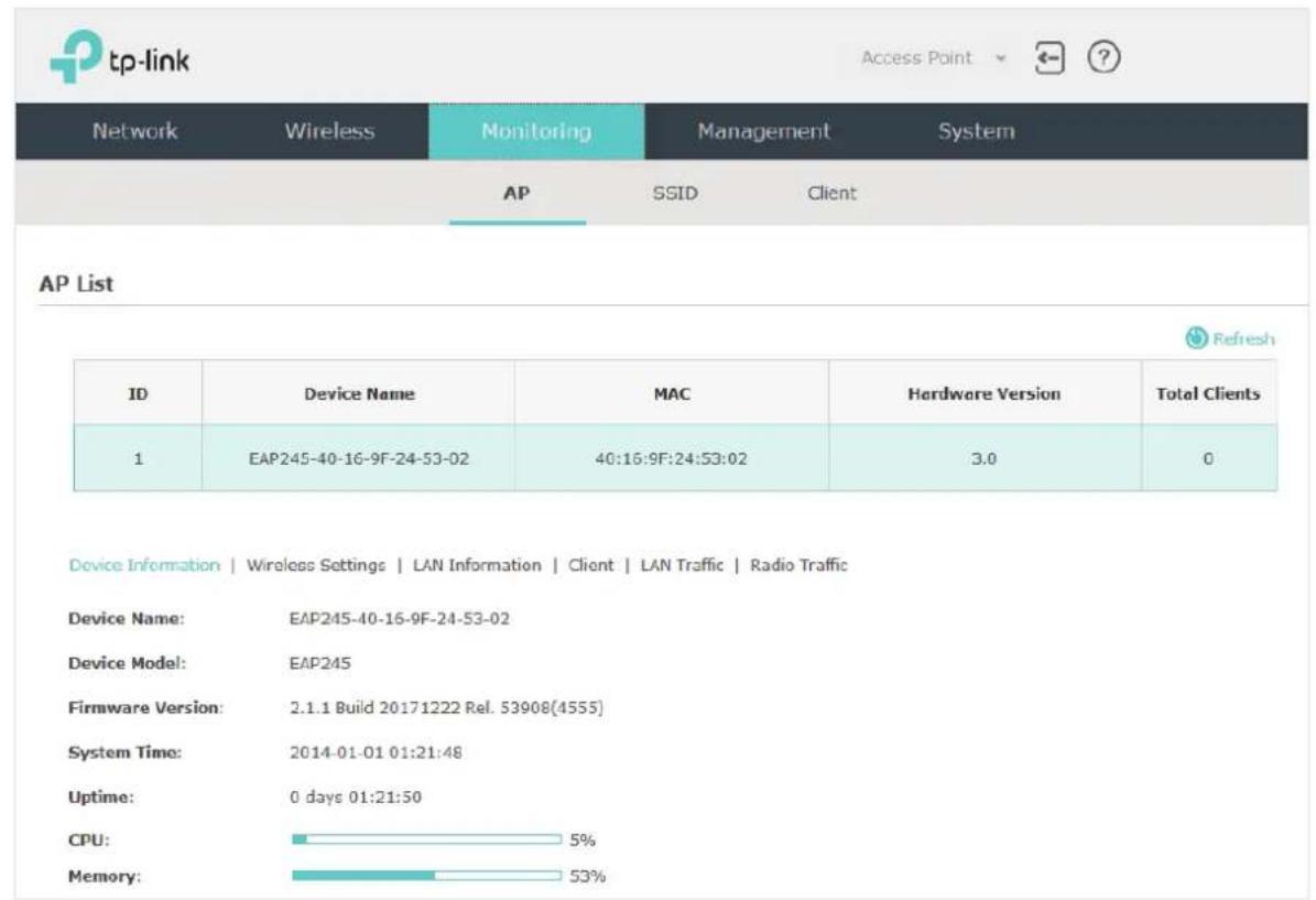
The AP List displays the following information:
Device Name Displays the name of the EAP. The name consists of the product model followed with the MAC address of the EAP.
MAC Displays the MAC address of the EAP.
Total Clients Displays the number of clients currently connected to the EAP.
View Device Information
Under this tab, you can view the device information of EAP.
| Device Information | Wireless Settings | LAN Information | Client | LAN Traffic | Radio Traffic | |
| Device Name: | EAP245-50-C7-BF-17-A6-E2 |
| Device Model: | EAP245 |
| Firmware Version: | 1.0.1 Build 20170414 Rel. 65957(4555) |
| System Time: | 2017-05-31 17:06:04 |
| Uptime: | 5 days 07:30:05 |
| CPU: | 2% |
| Memory: | 46% |
The following device information is displayed:
| Device Name Displays the name of the EAP. The name consists of the product model followed with the MAC address of the EAP. | |
| Device Model Displays the product model of the EAP. | |
| Firmware Version | Displays the current firmware version the EAP. To update the firmware, you can refer to Update the Firmware. |
| System Time Displays the current system time. To configure the system time, you can refer to Configure the System Time. | |
| Uptime Displays how long the EAP has been working since it starts up. | |
| CPU Displays the CPU occupancy. If this value is too high, the EAP may work abnormally. | |
| Memory Displays the memory occupancy. | |
View Wireless Settings
Under this tab, you can view the wireless settings of EAP.
Tips:
To change the wireless settings, you can refer to Configure the Wireless Parameters.
| Device Information | Wireless Settings | LAN Information | Client | LAN Traffic | Radio Traffic | |
| 2.4GHz | 5GHz | |
| Channel/Frequency: | 12 / 2467MHz |
| Channel Width: | 20/40MHz |
| IEEE802.11 Mode: | b/g/n mixed |
| Max TX Rate: | 450.0Mbps |
| Transmit Power: | 19dBm |
Note:
- For a dual-band EAP, there are two bands: 2.4GHz and 5GHz. You can click to select a band to view.
• The following figure posted in the introduction takes 2.4GHz as an example.
The following wireless information is displayed:
Channel/ Frequency Displays the channel and frequency which are currently used by the EAP.
Channel Width Displays the channel width which is currently used by the EAP.
IEEE802.11 Mode Displays the IEEE802.11 protocol currently used by the EAP.
Max TX Rate Displays the maximum physical rate of the EAP.
View LAN Information
Under this tab, you can view the LAN information of EAP.
Device Information | Wireless Settings | LAN Information | Client | LAN Traffic | Radio Traffic
MAC Address: 50-C7-BF-17-A6-E2
IP Address: 192.168.0.5
Subnet Mask: 255.255.255.0
LAN Port: 1000Mbps - FD
The following LAN information is displayed:
MAC Address Displays the MAC address of the EAP.
IP Address Displays the IP address of the EAP.
Subset Mask Displays the subnet mask of the EAP.
LAN Port Displays the maximum physical transmission rate and duplex mode of the port. HD meas half-duplex and FD means full-duplex.
View Client Information
Under this tab, you can view the client information of EAP.
Device Information | Wireless Settings | LAN Information | Client | LAN Traffic | Radio Traffic
| ID | MAC | Band | SSID | SNR(dB) | CCQ(%) | Rate (Mbps) | Down (Byte) | Up (Byte) | Active Time |
| 1 | 20-AB-37-84-9A-E2 | 2.4GHz | Office_market_2.4GHz | 18 | 100 | 1.0 | 43k | 46k | 0 days 00:00:43 |
The following client information is displayed:
MAC Displays the MAC address of the client.
Band Displays the frequency band the client is working on.
SSID Displays the SSID the client is connected to.
SNR (dB) Displays the Signal to Noise Ratio (SNR) of the client. SNR refers to the power ratio between the received wireless signal strength and the environmental noise strength. The bigger SNR value is, the better network performance the device can provide.
CCQ (%) Displays the wireless Client Connection Quality (CCQ). CCQ refers to the ratio between the current effective transmission bandwidth and the theoretical maximum available bandwidth. CCQ reflects the quality of the actual link. A bigger value means a better utilization of the bandwidth.
Rate (Mbps) Displays the wireless transmission rate of the client.
Down (Byte) Displays the client's total downloaded traffic from the EAP since the last connection.
Up (Byte) Displays the client's total uploaded traffic to the EAP since the last connection.
Active Time Displays how long the client has been connected to the EAP.
View LAN Traffic
Under this tab, you can view the LAN traffic of EAP.
Device Information | Wireless Settings | LAN Information | Client | LAN Traffic | Radio Traffic
Rx Packets: 105955
Tx Packets: 128601
Rx Bytes: 10847763
Tx Bytes: 93498247
Rx Dropped
Packets: 0
Tx Dropped Packets: 0
Rx Errors: 0
Tx Errors: 0
The following traffic information of the LAN is displayed:
Rx Packets Displays the total number of received packets in the LAN since the EAP starts up.
Tx Packets Displays the total number of sent packets in the LAN since the EAP starts up.
Rx Bytes Displays the total received traffic in the LAN since the EAP starts up.
Tx Bytes Displays the total sent traffic in the LAN since the EAP starts up.
Rx Dropped Packets Displays the total number of the dropped packets which are received by the EAP since it starts up.
Tx Dropped Packets Displays the total number of the dropped packets which are sent by the EAP since it starts up.
Rx Errors Displays the total number of the received error packets since the EAP starts up.
Tx Errors Displays the total number of the sent error packets since the EAP starts up.
View Radio Traffic
Under this tab, you can view the radio traffic of EAP.
| Device Information | Wireless Settings | LAN Information | Client | LAN Traffic | Radio Traffic | |||
| 2.4GHz | 5GHz | |||
| Rx Packets: | 43945726 | Tx Packets: | 9920997 |
| Rx Bytes: | 5608414053 | Tx Bytes: | 134826 |
| Rx Dropped Packets: | 0 | Tx Dropped Packets: | 0 |
| Rx Errors: | 0 | Tx Errors: | 10 |
The following traffic information of the radio is displayed:
| Rx Packets Displays the total number of the received packets on the 2.4GHz/5GHz band since the EAP starts up. | |
| Tx Packets Displays the total number of the sent packets on the 2.4GHz/5GHz band since the EAP starts up. | |
| Rx Bytes Displays the total received traffic on the 2.4GHz/5GHz band since the EAP starts up. | |
| Tx Bytes Displays the total sent traffic on the 2.4GHz/5GHz band since the EAP starts up. | |
| Rx Dropped Packets | Displays the total number of the dropped packets which are received on the 2.4GHz/5GHz band since the EAP starts up. |
| Tx Dropped Packets | Displays the total number of the dropped packets which are sent on the 2.4GHz/5GHz band since the EAP starts up. |
| Rx Errors Displays the total number of error packets which are received on the 2.4GHz/5GHz band since the EAP starts up. | |
| Tx Errors Displays the total number of error packets which are sent on the 2.4GHz/5GHz band since the EAP starts up. | |
3.2 Monitor the SSIDs
You can monitor the SSID information of the EAP.
To monitor the SSID information, go to the Monitoring > SSID page.

The following table introduces the displayed information of the SSID:
SSID Displays the SSID name.
VLAN ID Displays the VLAN ID of the SSID.
Total Clients Displays the number of clients currently connected to the SSID.
SSID Broadcast Displays whether the SSID broadcast is enabled.
Band Displays the frequency band the SSID is currently using.
Security Displays the security mode of the SSID.
Portal Displays whether portal authentication is enabled on the SSID.
MAC Filtering Displays whether MAC filtering is enabled on the SSID.
Isolation Displays whether SSID isolation is enabled on the SSID.
Down (Byte) Displays the total download traffic since the SSID starts working.
Up (Byte) Displays the total upload traffic since the SSID starts working.
3.3 Monitor the Clients
You can monitor the information of the clients connected to the EAP.
To monitor the client information, go to the Monitoring > Client page.
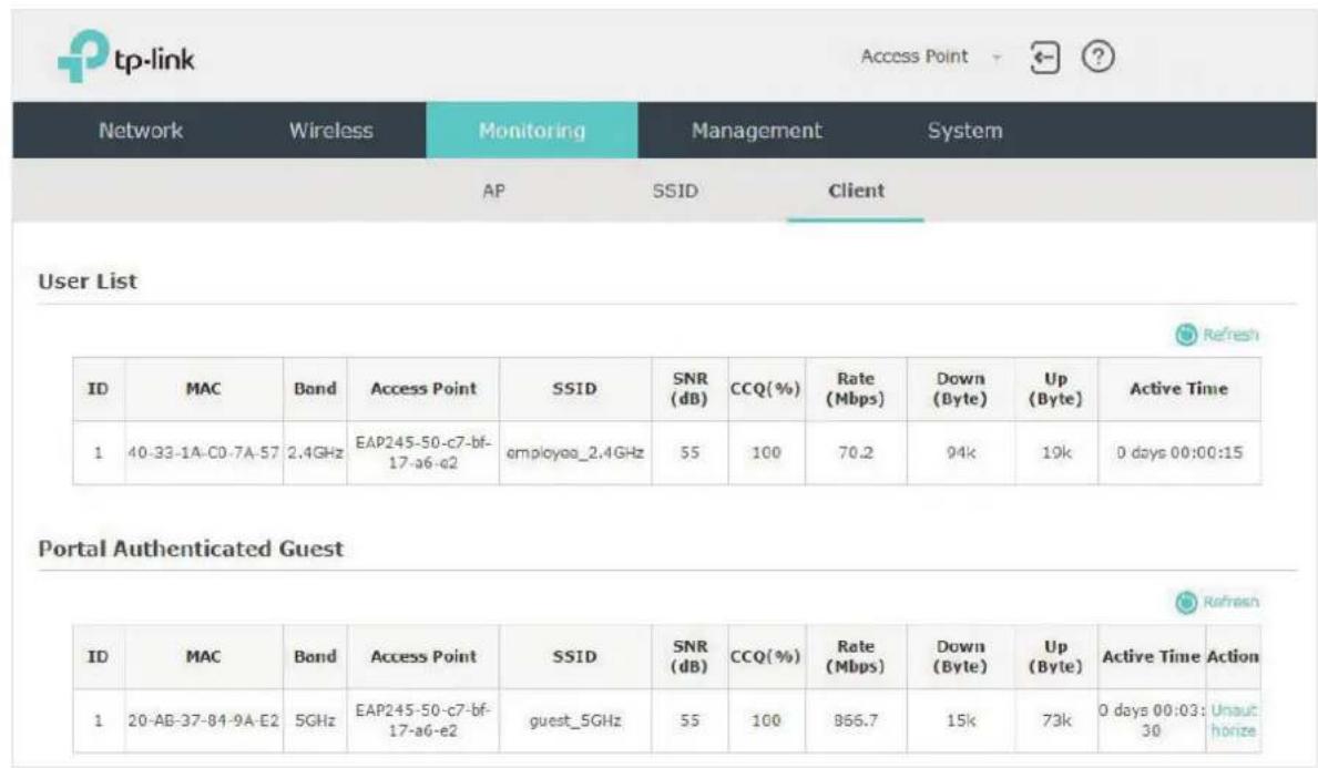
There are two types of clients: users and portal authenticated guests. Users are the clients that connect to the SSID with portal authentication disabled. Guests are the clients that connect to the SSID with portal authentication enabled.
View the Users
The following table introduces the displayed information of the users.
MAC Displays the MAC address of the user.
Band Displays the frequency band the user is working on.
Access Point Displays the device name of the EAP the user is connected to.
SSID Displays the SSID the user is connected to.
SNR (dB) Displays the Signal to Noise Ratio (SNR) of the user. SNR refers to the power ratio between the received wireless signal strength and the environmental noise strength. The bigger SNR value is, the better network performance the device can provide.
| CCQ (%) Displays the wireless Client Connection Quality (CCQ) of the user. CCQ refers to the ratio between the current effective transmission bandwidth and the theoretical maximum available bandwidth. CCQ reflects the quality of the actual link. A bigger value means a better utilization of the bandwidth. |
| Rate (Mbps) Displays the wireless transmission rate of the user. |
| Down (Byte) Displays the user's total downloaded traffic from the EAP since the last connection. |
| Up (Byte) Displays the user's total uploaded traffic to the EAP since the last connection. |
| Active Time Displays how long the user has been connected to the EAP. |
View and Manage the Portal Authenticated Guests
The following table introduces the displayed information of the portal authentication guests.
| MAC Displays the MAC address of the user. |
| Band Displays the frequency band the user is working on. |
| Access Point Displays the device name of the EAP the user is connected to. |
| SSID Displays the SSID the user is connected to. |
| SNR (dB) Displays the Signal to Noise Ratio (SNR) of the user. SNR refers to the power ratio between the received wireless signal strength and the environmental noise strength. The bigger SNR value is, the better network performance the device can provide. |
| CCQ (%) Displays the wireless Client Connection Quality (CCQ) of the user. CCQ refers to the ratio between the current effective transmission bandwidth and the theoretical maximum available bandwidth. CCQ reflects the quality of the actual link. A bigger value means a better utilization of the bandwidth. |
| Rate (Mbps) Displays the wireless transmission rate of the user. |
| Down (Byte) Displays the user's total downloaded traffic from the EAP since the last connection. |
| Up (Byte) Displays the user's total uploaded traffic to the EAP since the last connection. |
| Active Time Displays how long the user has been connected to the EAP. |
In the Action column, you can click Unauthorize to delete the authentication information of the guest. To access the internet, the guest needs to log in again.
4
Manage the EAP
The EAP provides powerful functions of device management and maintenance. This chapter introduces how to manage the EAP, including:
- Manage System Logs
- Configure Web Server
- Configure Management Access
- Configure Trunk (For EAP330)
- Configure LED
- Configure Wi-Fi Control (For EAP115-Wall)
- Configure PoE (For EAP225-Wall)
- Configure SSH
- Configure Management VLAN
- Configure SNMP
4.1 Manage System Logs
System logs record information about hardware, software as well as system issues and monitors system events. With the help of system log, you can get informed of system running status and detect the reasons for failure.
To manage system logs, go to the Management > System Log page.

On this page, you can view the system logs and configure the way of receiving system logs. For EAP320/EAP330/EAP225, you can also backup the system logs to your local host.
View System Logs
In the Log section, you can click to refresh the logs and view them in the table.
Log
Refresh
| Index | Time | Type | Level | Log Content |
| 3 | 2014-01-01 01:32:54 | OTHER | WARNING | LAN IP and mask changed to 192.168.0.S |
| 2 | 1970-01-01 00:00:11 | OTHER | WARNING | LAN IP and mask changed to 192.168.0.245 |
| 1 | 1970-01-01 00:00:05 | OTHER | INFO | S |
Configure the Way of Receiving Logs
In the Log Settings section, you can configure the ways of receiving system logs.
Log Settings
Enable Auto Mail:
□ Auto Mail Feature
Enable Server:
Enable Server
Save
Follow the steps below to configure this feature:
- Check the corresponding box to enable one or more ways of receiving system logs, and configure the related parameters. Two ways are available: Auto Mail and Server.
■ Auto Mail
If Auto Mail is configured, system logs will be sent to a specified mailbox. Check the box to enable the feature and configure the related parameters.
Note:
SSL encryption is not currently supported.
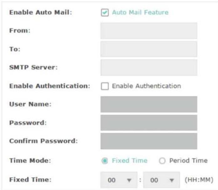
The following table introduces how to configure these parameters:
| From Enter the sender's E-mail address. | |
| To Enter the receiver's E-mail address. | |
| SMTP Server Enter the IP address of the sender's SMTP server. | |
| Note: At present, the domain name of SMTP server is not supported in this field. | |
| Enable Authentication | If the sender's mailbox is configured with You can check the box to enable mail server authentication. Enter the sender's username and password. |
| Time Mode | Select Time Mode: Fixed Time or Period Time.Fixed Time means that the system logs will be sent at the specific time every day. Period Time means that the system logs will be sent at the specific time interval. |
| Fixed Time | If you select Fixed Time, specify a fixed time to send the system log mails. For example, 08:30 indicates that the mail will be sent at 8:30 am everyday. |
| Period Time | If you select Period Time, specify a period time to regularly send the system log mail. For example, 6 indicates that the mail will be sent every six hours. |
■ Server
If Server is configured, system logs will be sent to the specified system log server, and you can use the syslog software to view the logs on the server.
Enable this feature and enter the IP address and port of the system log server.
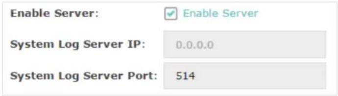
2. Click Save.
Backup Logs (For EAP320/EAP330/EAP225)
In the Backup Log section, you can click to backup the current system logs into a file and save the file on your local host.

4.2 Configure Web Server
With the web server, you can log in to the management web page of the EAP. You can configure the web server parameters of the EAP according to your needs.
To configure Web Server, go to the Management > Web Server page.

Follow the steps below to configure Web Server:
- Refer to the following table to configure the parameters:
Secure Server Port Designate a secure server port for web server in HTTPS mode. By default the port is 443.
Server Port Designate a server port for web server in HTTP mode. By default the port is 80.
Session Timeout Set the session timeout. If you do nothing with the web page within the timeout, the system will log out automatically. You can log in again if you want to go back to web page.
- Click Save.
4.3 Configure Management Access
By default, all hosts in the LAN can log in to the management web page of the EAP with the correct username and password. To control the hosts' access to the web page of the EAP, you can specify the MAC addresses of the hosts that are allowed to access the web page, and other hosts without MAC addresses specified are not allowed to access the web page.
To configure Management Access, go to the Management > Management Access page.

Follow the steps below to configure Management Access on this page:
- Check the box to enable MAC Authentication.
- Specify one or more MAC addresses in the MAC1/MAC2/MAC3/MAC4 fields. Up to four MAC addresses can be added.
- Click Save.
Tips:
- You can click Add PC's MAC Address to quickly add the MAC address of your current logged-in host, .
- Verify the MAC addresses carefully. Once the settings are saved, only the hosts in the MAC address list can access the web page of the EAP.
- If you cannot log in to the web page after saving the wrong configuration, you can reset the EAP to the factory defaults and use the default username and password (both admin) to log in.
4.4 Configure Trunk (For EAP330)
The trunk function can bundle multiple Ethernet links into a logical link to increase bandwidth and improve network reliability. The EAP330 has two 1000Mbps Ethernet ports. If the Trunk function is enabled and the ports are in the speed of 1000Mbps Full Duplex, the whole bandwidth of the trunk link is up to 4Gbps (2000Mbps * 2).
Note:
The trunk feature here refers to static trunk. Make sure that the trunk mode of the peer is static.
To configure Trunk, go to the Management > Trunk page.

Follow the steps below to configure Trunk on this page:
- Check the box to enable Trunk.
- Select the trunk algorithm mode from the drop-down list. Three options are available: SRC MAC+DST MAC, DST MAC and SRC MAC. Based on the selected algorithm mode, the EAP determines which physical port is used to send out the received packet.
- With SRC MAC+DST MAC selected, the EAP determines the outgoing port based on both the source and destination MAC addresses of the packet.
- With DST MAC selected, the EAP determines the outgoing port baesed on the destination MAC address of the packet.
- With SRC MAC selected, the EAP determines the outgoing port based on the source MAC address of the packet.
3. Click Save.
4.5 Configure LED
You can turn on or off the LED light of the EAP.
To configure LED, go to the Management > LED ON/OFF page.
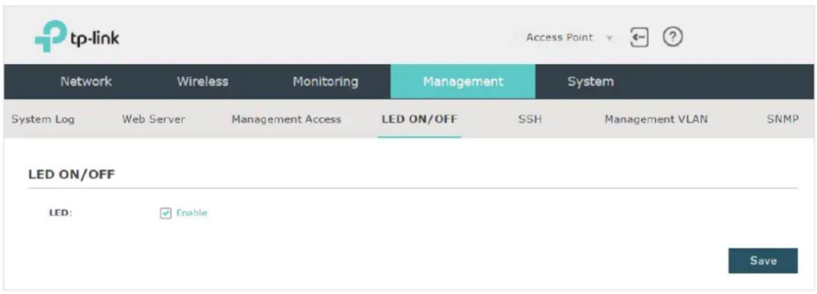
Check the box to turn on or turn off the LED light of the EAP, and click Save.
4.6 Configure Wi-Fi Control (For EAP115-Wall)
EAP115-Wall has an LED/Wi-Fi button on the front panel. With Wi-Fi Control enabled, you can press the button to turn on or off both of the Wi-Fi and LED at the same time.
To configure Wi-Fi Control, go to the Management > Wi-Fi Control page.
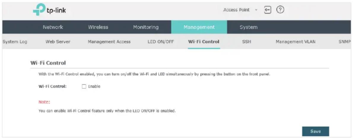
Check the box to enable Wi-Fi Control and click Save.
Note:
You can enable Wi-Fi Control only when the option LED ON/OFF is enabled.
4.7 Configure PoE (For EAP225-Wall)
EAP225-Wall has a PoE out port that can transmit data and supply power to the client simultaneously. You can also disable the PoE feature to make the port transmit data only.
To configure PoE, go to the Management > PoE Out page.
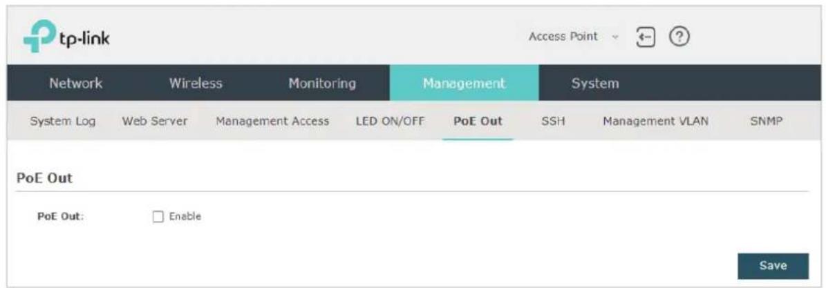
Check the box to enable the PoE feature and click Save.
4.8 Configure SSH
If you want to remotely log in to the EAP via SSH, you can deploy an SSH server on your network and configure the SSH feature on the EAP.
To configure SSH, go to the Management > SSH page.
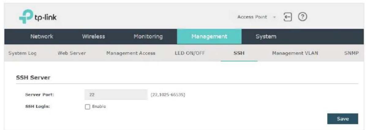
Follow the steps below to configure SSH on this page:
- Enter the port number of the SSH server.
- Check the box to enable SSH Login. By default, it is disabled.
- Click Save.
4.9 Configure Management VLAN
Management VLAN provides a safer method to manage the EAP. With Management VLAN enabled, only the hosts in the Management VLAN can access the web page of the EAP. Since most hosts cannot process VLAN TAGs, you can connect the management host to the network via a switch, and set up correct VLAN settings for the switches on the network to ensure the communication between the host and the EAP in the Management VLAN.
To configure Management VLAN, go the Management > Management VLAN page.

Follow the steps below to configure Management VLAN on this page:
- Check the box to enable Management VLAN.
- Specify the VLAN ID of the management VLAN. Only the hosts in the Management VLAN can log in to the EAP via the Ethernet port.
- Click Save.
4.10 Configure SNMP
The EAP can be configured as an SNMP agent and work together with the SNMP manager. Once the EAP has become an SNMP agent, it is able to receive and process request messages from the SNMP manager. At present, the EAP supports SNMP v1 and v2c.
To configure the EAP as an SNMP agent, go to the Management > SNMP page.

Follow the steps below to complete the configuration on this page:
- Check the box to enable SNMP Agent.
- Refer to the following table to configure the required parameters:
| SysContact Enter the textual identification of the contact person for this managed node. |
| SysName Enter an administratively-assigned name for this managed node. |
| SysLocation Enter the physical location of this managed node. |
| Get Community Community refers to a host group aiming at network management.Get Community only has the read-only right of the device's SNMP information. The community name can be considered a group password. The default setting is public. |
| Get Source Defines the IP address (for example, 10.10.10.1) for management systems that can serve as Get Community to read the SNMP information of this device. The default is 0.0.0.0, which means all hosts can read the SNMP information of this device. |
| Set Community Set Community has the read and write right of the device's SNMP information. Enter the community name that allows read/write access to the device's SNMP information. The community name can be considered a group password. The default setting is private. |
Set Source Defines the IP address (for example, 10.10.10.1) for management systems that can serve as Set Community to read and write the SNMP information of this device. The default is 0.0.0.0, which means all hosts can read and write the SNMP information of this device.
3. Click Save.
Note:
Defining community can allow management systems in the same community to communicate with the SNMP Agent. The community name can be seen as the shared password of the network hosts group. Thus, for the security, we recommend that modify the default community name before enabling the SNMP Agent service. If the field of community is blank, the SNMP Agent will not respond to any community name.
5 Configure the System
This chapter introduces how to configure the system of the EAP, including:
- Configure the User Account
- Configure the System Time
• Reboot and Reset the EAP - Backup and Restore the Configuration
- Update the Firmware
5.1 Configure the User Account
Every EAP device has a user account, which is used to log in to the management page of the EAP. When you start the EAP at the first time, the username and password of the user account are both admin. After the first login, the system will require you to set a new username and a new password for the user account. And then you can use the new user account to log in to the EAP. Also, you can change your user account as needed.
Tips:
Please remember your user account well. If you forget it, reset the EAP to the factory defaults and log in with the default user account (username and password are both admin).
To configure the user account, go to System > User Account page.
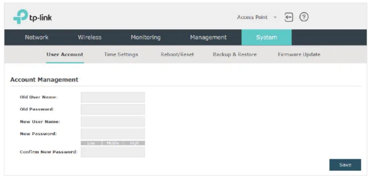
Follow the steps below to change your user account on this page:
- Enter the old username and old password of your user account.
- Specify a new username and a new password for your user account. The system will automatically detect the strength of your entered password. For security, we recommend that you set a password with high strength.
- Retype the new password.
- Click Save.
5.2 Configure the System Time
System time is the standard time for Scheduler and other time-based functions. The EAP supports the basic system time settings and the Daylight Saving Time (DST) feature.
To configure the system time, go to the System > Time Settings page.

The following two sections introduce how to configure the basic system time settings and the Daylight Saving Time feature.
Configure the System Time
In the Time Settings section, you can configure the system time. There are three methods to set the system time: Set the System Time Manually, Acquire the System Time From an NTP Server, and Synchronize the System Time with PC's Clock.

Determine the way of setting the system time and follow the steps below to complete the configurations:
- Set the System Time Manually
To set the system time manually, follow the steps below:
- Configure the following three options on the page: Time Zone, Date and Time.
Time Zone Select your time zone from the drop-down list. Here GMT means Greenwich Mean Time.
Date Specify the current date in the format MM/DD/YYYY. MM means month, DD means day and YYYY means year. For example: 06/01/2017.
Time Specify the current time in the format HH/MM/SS. HH means hour, MM means minute and SS means second. It uses 24-hour system time. For example: 14:36:21.
2. Click Save.
Note:
The system time set manually will be lost after the EAP is rebooted.
• Acquire the System Time From an NTP Server
To get the system time from an NTP server, follow the steps below:
- Build an NTP server on your network and make sure that it is reachable by the EAP. Or you can simply find an NTP server on the internet and get its IP address.
Note:
If you use an NTP server on the internet, make sure that the gateway address is set correctly on the EAP. Otherwise, the EAP cannot get the system time from the NTP server successfully. To set the gateway address, refer to Configure the IP Address of the EAP.
- Specify the NTP server for the EAP. If you have two NTP servers, you can set one of them as the primary NTP server, and the other as the secondary NTP server. Once the primary NTP server is down, the EAP can get the system time from the secondary NTP server.
| Primary NTP Server | Enter the IP address of the primary NTP server. Note: If you have only one NTP server on your network, enter the IP address of the NTP server in this field. |
| Secondary NTP Server | Enter the IP address of the secondary NTP server. |
-
Click the button Get GMT and the acquired system time will be displayed in the Date and Time fields.
-
Click Save.
- Synchronize the System Time with PC's Clock
To synchronize the system time with the clock of your currently logged-in host, follow the steps below:
-
Click the button Synthe is synth beized system time will be displayed in the Date and Time fields.
-
Click Save.
Note:
The system time synchronized with PC's clock will be lost after the EAP is rebooted.
Configure Daylight Saving Time
Daylight saving time is the practice of advancing clocks during summer months so that evening daylight lasts longer, while sacrificing normal sunrise times. The EAP provides daylight saving time configuration.

Follow the steps below to configure daylight saving time:
-
Check the box to enable Daylight Saving.
-
Select the mode of daylight saving time. Three modes are available: Predefined Mode, Recurring Mode and Date Mode.
-
Configure the related parameters of the selected mode.
■ Predefined Mode
If you select Predefined Mode, choose your region from the drop-down list and the EAP will use the predefined daylight saving time of the selected region.

There are four regions provided: USA, European, Austrilia and New Zealand. The following table introduces the predefined daylight saving time of each region.
USA From 2:00 a.m. on the Second Sunday in March to 2:00 a.m. on the First Sunday in November.
European From 1:00 a.m. on the Last Sunday in March to 1:00 a.m. on the Last Sunday in October.
Australia From 2:00 a.m. on the First Sunday in October to 3:00 a.m. on the First Sunday in April.
New Zealand From 2:00 a.m. on the Last Sunday in September to 3:00 a.m. on the First Sunday in April.
■ Recurring Mode
If you select Recurring Mode, manually specify a cycle time range for the daylight saving time of the EAP. This configuration will be used every year.
Mode:
○ Predefined Mode
Recurring Mode Date Mode
Time Offset:

minutes (1-180)
Start:
End:


The following table introduces how to configure the cycle time range.
Time Offset Specify the time to set the clock forward by.
Start Specify the start time of daylight saving time. The interval between the start time and end time should be more than 1 day and less than 1 year (365 days).
End Specify the end time of daylight saving time. The interval between the start time and end time should be more than 1 day and less than 1 year (365 days).
Date Mode
If you select Date Mode, manually specify an absolute time range for the daylight saving time of the EAP. This configuration will be used only once.

The following table introduces how to configure the absolute time range.
Time Offset Specify the time to set the clock forward by.
Start Specify the start time of daylight saving time. The interval between the start time and end time should be more than 1 day and less than 1 year (365 days).
End Specify the end time of daylight saving time. The interval between the start time and end time should be more than 1 day and less than 1 year (365 days).
4. Click Save.
5.3 Reboot and Reset the EAP
You can reboot and reset the EAP according to your need.
To reboot and reset the EAP, go to the System > Reboot&Reset page.
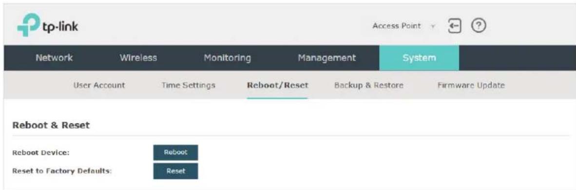
- To reboot the EAP, click the reboot, and the EAP will be rebooted automatically. Please wait without any operation.
- To reset the EAP, click the Reset button, and the EAP will be reset to the factory defaults automatically. Please wait without any operation.
Note:
After reset, all the current configuration of the EAP will be lost. We recommend that you check whether you have any configuration that needs to be backed up before resetting the EAP.
5.4 Backup and Restore the Configuration
You can save the current configuration of the EAP as a backup file and save the file to your host. And if needed, you can use the backup file to restore the configuration. We recommend that you backup the configuration before resetting or upgrading the EAP.
To backup and restore the configuration, go to the System > Backup&Restore page.
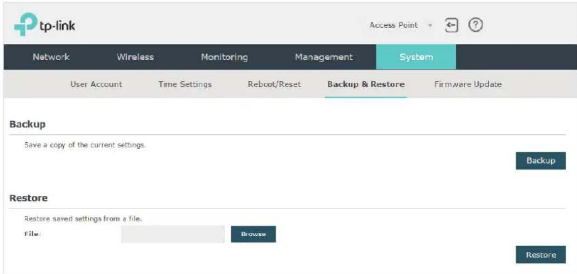
- To backup the configuration, click the button to 'Backup' and the backup file will be saved to the host automatically.
- To restore the configuration, click the button Browse in the Restore section and choose the backup file from the host. Then click the button Restore to restore the configuration.
5.5 Update the Firmware
We occasionally provide the firmware update files for the EAP products on our official website. To get new functions of the EAP, you can check our official website and download the update files to update the firmware of your EAP.
To update the firmware, go to the System > Firmware Update page.
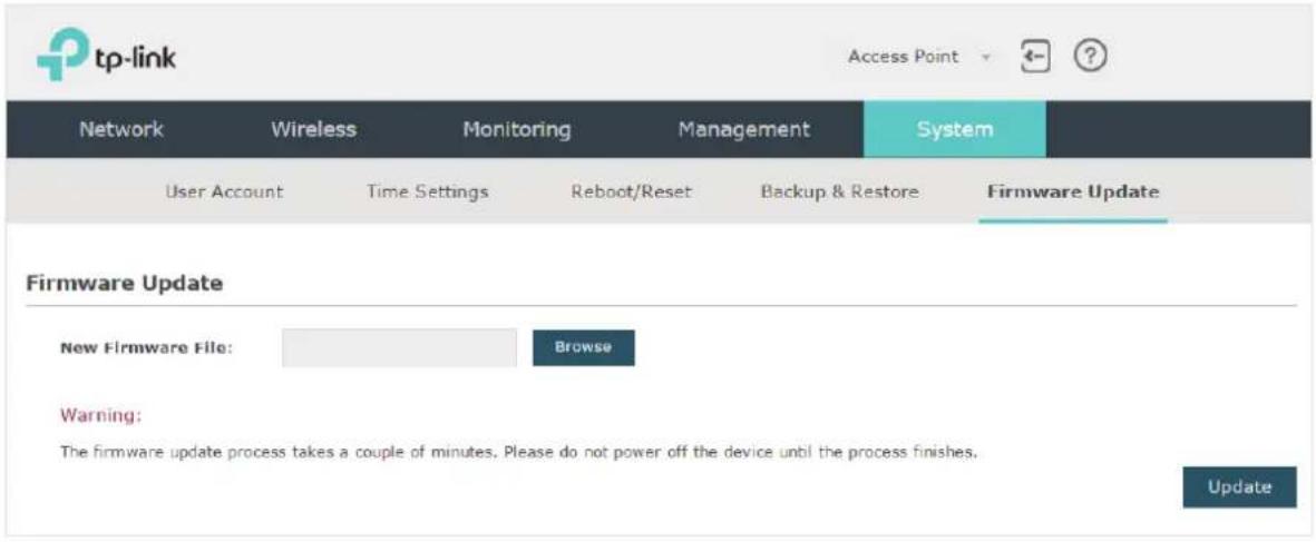
Follow the steps below to update the firmware of your EAP:
- Go to our website www.tp-link.com and search your EAP model. Download the proper firmware file on the support page of the EAP.
- Click the button Browse, locate and choose the correct firmware file from your host.
- Click the button Update to update the firmware of the EAP. After updated, the EAP will be rebooted automatically.
Note:
The update process takes several minutes. To avoid damage to the EAP, please wait without any operation until the update is finished.
6
Application Example
This chapter provides an application example about how to establish and manage a EAP wireless network:
A restaurant wants to provide the wireless internet access for the employees and guests. The restaurant now has a router, a switch, a dual-band EAP and a computer. Follow the steps below to establish the wireless network:
- Build the Network Topology
- Log in to the EAP
- Configure the EAP
-
Test the Network
-
Determine the Network Requirements
6.1 Determine the Network Requirements
Before starting to build the network, we need to first analyze and determine the network requirements. In this restaurant example, the network requirements are as follows:
- On both 2.4GHz and 5GHz bands, there are two SSIDs needed: one for the restaurant employees and one for the guests.
- In order to advertise the restaurant, the Portal feature needs to be configured on the SSIDs for the guests. In this way, the guests who have passed the portal authentication will be redirected to the restaurant's official website http://www.restaurant1.com.
- The employees of the restaurant can use the correct password to access the internet and do not need to pass the portal authentication. For security, the SSIDs for the employees should be encrypted with WPA2-PSK.
- To reduce power consumption, the Scheduler feature needs to be configured. The radio should operate only during the working time (9:00 am to 22:00 pm).
6.2 Build the Network Topology
Build the network topology as the following figure shows.
![graph LR A["Management Host"] --> B["Switch"] B --> C["Router (DHCP Server)\nLAN: 192.168.88.1"] B --> D["EAP"] C --> E["Internet"]](/content/2026/06/1329068/images/5298c129b34b53beaf6c8d0735fbd5c9450243c06315d03fb1c0c28806e68a4f.jpg)
- The router is the gateway of the network and acts as a DHCP server to assign dynamic IP addresses to the management host, EAP and clients. The LAN IP of the router is 192.168.88.1/24.
- Connect the switch to the LAN port of the router.
- Connect the management host and the EAP to the switch. The IP address mode of the management host and EAP is dynamic, which means that they will get dynamic IP addresses from the router.
Tips:
If the router has more than one LAN port, we can also respectively connect the management host and the EAP to the LAN ports of the router.
6.3 Log in to the EAP
After building the network topology, follow the steps below to log in to the web page of the EAP:
- On the management host, launch the web browser and enter "192.168.88.1" in the address bar. Then log in to the router and find the IP address of the EAP. As the following figure shows, the IP address of the EAP is 192.168.88.101.
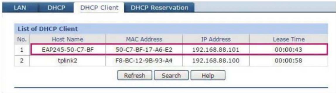
- Enter "192.168.88.101" in the address bar to load the login page of the EAP. Type the default username and password (both admin) in the two fields and click LOGIN.
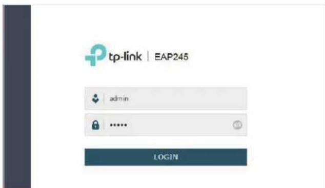
- In the pop-up window, specify a new username and a new password for the user account. Click Confirm.
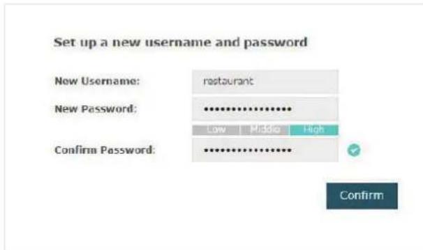
- Enter the new username and new password and click LOGIN. Then we can enter the web page of the EAP.

6.4 Configure the EAP
To achieve the network requirements in this application example, we need to Configure SSIDs, Configure Portal Authentication and Configure Scheduler.
Configure SSIDs
Follow the steps below to respectively configure SSIDs for the employees and guests on the 2.4GHz band and 5GHz band:
- Go to the Wireless > Wireless Settings page.
- In the SSIDs section, there is already a default SSID on the 2.4GHz band. Click
SSIDs
| ID | SSID | Wireless VLAN ID | SSID Broadcast | Security Mode | Portal | SSID Isolation | Modify |
| 1 | TP-LINK_2.4GHz_17A6E2 | 0 | Enable | None | Disable | Disable |
- The following page will appear. Configure this SSID for the employees. Change SSID to "employee_2.4GHz", select the Security Mode as "WPA2-PSK", and specify the Wireless Password as "restaurant123abc". Click OK.

- On the same page, click to add a new SSID.
| ID | SSID | Wireless VLAN ID | SSID Broadcast | Security Mode | Portal | SSID Isolation | Modify |
| 1 | employee_2.4GHz | 0 | Enable | WPA-PSK | Disable | Disable |
- The following page will appear. Configure this SSID for the guests. Change SSID to "guest_2.4GHz", keep the Security Mode as "None" and check the box to enable the Portal feature for this SSID. Click OK.
| ID | SSID | Wireless VLAN ID | SSID Broadcast | Security Mode | Portal | SSID Isolation | Modify |
| - | - | - | - | - | - | - | - |
| SSID: | guest_2.4GHz | ||||||
| Wireless VLAN ID: | 0 | (0-4094, 0 is used to disable VLAN tagging.) | |||||
| SSID Broadcast: | ✓ Enable | ||||||
| Security Mode: | None | ||||||
| Portal: | ✓ Enable | ||||||
| SSID Isolation: | ☐ Enable | ||||||
| Cancel | OK | ||||||
- Click 2.4GHz 5GHz to enter the configuration page for the 5GHz band. Similarly to the configurations for the 2.4GHz band, configure two SSIDs for the employees and guests on the 5GHz band.
Configure Portal Authentication
Follow the steps below to configure portal authentication:
-
Go to the Wireless > Portal page.
-
Configure the portal feature as the following figure shows.

1) Select the Authentication Type as "Local Password" and specify the Password as "restaurant123".
2) Configure Authentication Timeout. Here we customize the timeout as 2 hours. It means that guests will be logged out after they have been authenticated for 2 hours. To continue to use the internet service, these guests need to enter the password to pass the portal authentication once again.
3) Check the box to enable Redirect, and enter the website of the restaurant: http://www.restaurant1.com.
4) Configure the authentication page. Specify the title and the term of use. To access the internet, guests need to enter the correct password in the Password field, accept the Term of Use, and click the Login button.
- Click Save.
Configure Scheduler
Follow the steps below to schedule the radio to operate only during the working time (9:00 am to 22:00 pm).
- Go to the Wireless > Scheduler page.
- In the Settings section, check the box to enable Scheduler, and select the Association Mode as "Associated with AP". Click Save.
Settings
Scheduler:
Association Mode:
Enable
Associated with AP
7
Save
- In the Scheduler Profile Configuration section, click + Create Profiles
Scheduler Profile Configuration

Create Profiles
1) The following page will appear. Click Add a Profile and specify the profile name as "worktime". Click OK.
Scheduler Profile Configuration

2) Choose the newly added profile "worktime", and click + Add an item. Then the item configuraiton page will appear. Specify the time range as everyday 9:00 to 22:00. Click OK.

- In the Scheduler Association section, select "worktime" in the Profile Name column and select "Radio On" in the Action column. Click Save.
Scheduler Association
| ID | AP | AP MAC | Profile Name | Action |
| 1 | EAP245-50-c7-bf-17-a6-e2 | 50-C7-BF-17-A6-E2 | worktime | Radio On |
6.5 Test the Network
To ensure that the employees and guests can surf the internet via the wireless network, we can use a client device, such as a telephone, to test whether the SSIDs are working normally.
• To test the SSIDs for the employees, follow the steps below:
1) Enable the Wi-Fi feature of the client device.
2) Choose the SSID "employee_2.4GHz" or "employee_5GHz" among the detected SSIDs.
3) Enter the password "restaurant123abc" to join the wireless network.
4) Check whether internet websites can be visited successfully.
• To test the SSIDs for the guests, follow the steps below:
1) Enable the Wi-Fi feature of the client device.
2) Choose the SSID "guest_2.4GHz" or "guest_5GHz" among the detected SSIDs.
3) The default web browser on the device will pop up and the authentication page will appear. Enter the password "restaurant123", check the box to accept the term of use, and click the LOGIN button.
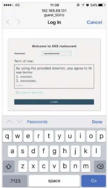
Tips:
Generally, the web browser pops up automatically. But if the web browser does not pop up, we can manually launch the web browser and visit any http website. Then the authentication page will appear.
4) If the network is working normally, we will be redirected to the website of the restaurant: http://www.restaurant1.com.

FCC Compliance Information Statement

Product Name: Omada EAP
Model Number: EAP110 / EAP115 / EAP225 / EAP245 / EAP320 / EAP330 / EAP115-Wall / EAP110-Outdoor / EAP225-Outdoor / EAP225-Wall
| Component Name | Model |
| I.T.E POWER SUPPLY | T090060-2B1(For EAP115)T120150-2B1(For EAP245/EAP320)TL-POE2412G(For EAP110/EAP110-Outdoor/EAP225-Outdoor/EAP225-Wall) |
| SWITCHING POWER SUPPLY S030 | ABU1200250 |
Responsible party:
TP-Link USA Corporation, d/b/a TP-Link North America, Inc.
Address: 145 South State College Blvd. Suite 400, Brea, CA 92821
Website: http://www.tp-link.com/us/
Tel: +1 626 333 0234
This equipment has been tested and found to comply with the limits for a Class B digital device, pursuant to part 15 of the FCC Rules. These limits are designed to provide reasonable protection against harmful interference in a residential installation. This equipment generates, uses and can radiate radio frequency energy and, if not installed and used in accordance with the instructions, may cause harmful interference to radio communications. However, there is no guarantee that interference will not occur in a particular installation. If this equipment does cause harmful interference to radio or television reception, which can be determined by turning the equipment off and on, the user is encouraged to try to correct the interference by one or more of the following measures:
- Reorient or relocate the receiving antenna.
- Increase the separation between the equipment and receiver.
- Connect the equipment into an outlet on a circuit different from that to which the receiver is connected.
- Consult the dealer or an experienced radio/ TV technician for help.
This device complies with part 15 of the FCC Rules. Operation is subject to the following two conditions:
1) This device may not cause harmful interference.
2) This device must accept any interference received, including interference that may cause undesired operation.
Any changes or modifications not expressly approved by the party responsible for compliance could void the user's authority to operate the equipment.
Note: The manufacturer is not responsible for any radio or TV interference caused by unauthorized modifications to this equipment. Such modifications could void the user's authority to operate the equipment.
FCC RF Radiation Exposure Statement:
This equipment complies with FCC RF radiation exposure limits set forth for an uncontrolled environment. This device and its antenna must not be co-located or operating in conjunction with any other antenna or transmitter.
"To comply with FCC RF exposure compliance requirements, this grant is applicable to only Mobile Configurations. The antennas used for this transmitter must be installed to provide a separation distance of at least 20cm (28cm for EAP320, 46cm for EAP330) from all persons and must not be colocated or operating in conjunction with any other antenna or transmitter."
We, TP-Link USA Corporation, has determined that the equipment shown as above has been shown to comply with the applicable technical standards, FCC part 15. There is no unauthorized change is made in the equipment and the equipment is properly maintained and operated.
Issue Date:2018-01-25
FCC Compliance Information Statement

Product Name: I.T.E POWER SUPPLY
Model Number: T090060-2B1, T120150-2B1, TL-POE2412G
Product Name: SWITCHING POWER SUPPLY
Model Number: S030ABU1200250
Responsible party:
TP-Link USA Corporation, d/b/a TP-Link North America, Inc.
Address: 145 South State College Blvd. Suite 400, Brea, CA 92821
Website: http://www.tp-link.com/us/
Tel: +1 626 333 0234
This equipment has been tested and found to comply with the limits for a Class B digital device, pursuant to part 15 of the FCC Rules. These limits are designed to provide reasonable protection against harmful interference in a residential installation. This equipment generates, uses and can radiate radio frequency energy and, if not installed and used in accordance with the instructions, may cause harmful interference to radio communications. However, there is no guarantee that interference will not occur in a particular installation. If this equipment does cause harmful interference to radio or television reception, which can be determined by turning the equipment off and on, the user is encouraged to try to correct the interference by one or more of the following measures:
- Reorient or relocate the receiving antenna.
- Increase the separation between the equipment and receiver.
- Connect the equipment into an outlet on a circuit different from that to which the receiver is connected.
- Consult the dealer or an experienced radio/ TV technician for help.
This device complies with part 15 of the FCC Rules. Operation is subject to the following two conditions:
1) This device may not cause harmful interference.
2) This device must accept any interference received, including interference that may cause undesired operation.
Any changes or modifications not expressly approved by the party responsible for compliance could void the user's authority to operate the equipment.
We, TP-Link USA Corporation, has determined that the equipment shown as above has been shown to comply with the applicable technical standards, FCC part 15. There is no unauthorized change is made in the equipment and the equipment is properly maintained and operated.
Issue Date:2018-01-25
CE Mark Warning
CE
This is a class B product. In a domestic environment, this product may cause radio interference, in which case the user may be required to take adequate measures.
OPERATING FREQUENCY(the maximum transmitted power)
EU declaration of conformity
TP-Link hereby declares that the device is in compliance with the essential requirements and other relevant provisions of directives 2014/53/EU, 2009/125/EC and 2011/65/EU.
The original EU declaration of conformity may be found at http://www.tp-link.com/en/ce.
RF Exposure Information
This device meets the EU requirements (2014/53/EU Article 3.1a) on the limitation of exposure of the general public to electromagnetic fields by way of health protection.
The device complies with RF specifications when the device used at 20 cm from your body.
National Restrictions (EAP320/EAP330/EAP225/EAP245/EAP225-Wall)
Restricted to indoor use.
Canadian Compliance Statement
This device complies with Industry Canada license-exempt RSSs. Operation is subject to the following two conditions:
1) This device may not cause interference, and
2) This device must accept any interference, including interference that may cause undesired operation of the device.
This radio transmitter (IC: 8853A-EAP110OD / Model: EAP110-Outdoor) has been approved by Industry Canada to operate with the antenna types listed below with the maximum permissible gain indicated. Antenna types not included in this list below, having a gain greater than the maximum gain indicated for that type, are strictly prohibited for use with this device.
This radio transmitter (IC: 8853A-EAP225OD / Model: EAP225-Outdoor) has been approved by Industry Canada to operate with the antenna types listed below with the maximum permissible gain indicated. Antenna types not included in this list below, having a gain greater than the maximum gain indicated for that type, are strictly prohibited for use with this device.
1) The device for operation in the band 5150–5250 MHz is only for indoor use to reduce the potential for harmful interference to co-channel mobile satellite systems;
2) For devices with detachable antenna(s), the maximum antenna gain permitted for devices in the bands 5250-5350 MHz and 5470-5725 MHz shall be such that the equipment still complies with the e.i.r.p. limit; (For EAP225-Outdoor only)
3) For devices with detachable antenna(s), the maximum antenna gain permitted for devices in the band 5725-5850 MHz shall be such that the equipment still complies with the e.i.r.p. limits specified for point-to-point and non-point-to-point operation as appropriate; and
The high-power radars are allocated as primary users (i.e. priority users) of the bands 5250-5350 MHz and 5650-5850 MHz and that these radars could cause interference and/or damage to LE-LAN devices.
DFS (Dynamic Frequency Selection) products that operate in the bands 5250-5350 MHz, 5470-5600MHz, and 5650-5725MHz. (For EAP245 and EAP225-Outdoor).
Avertissement
Radiation Exposure Statement
This equipment complies with ISEDC radiation exposure limits set forth for an uncontrolled environment. This equipment should be installed and operated with minimum distance (20cm for EAP110/EAP115/EAP245/EAP115-Wall/EAP110-Outdoor/EAP225-Outdoor/EAP225-Wall, 35cm for EAP 320, 46cm for EAP330, and 24cm for EAP225) between the radiator & your body.
Industry Canada Statement
CAN ICES-3 (B)/NMB-3(B)
Korea Warning Statements
When product has power button, the power button is one of the way to shut off the product; When there is no power button, the only way to completely shut off power is to disconnect the product or the power adapter from the power source.
- Keep the device away from water, fire, humidity or hot environments.
- Do not attempt to disassemble, repair, or modify the device.
- Do not use damaged charger or USB cable to charge the device.
- Do not use any other chargers than those recommended
- Do not use the device where wireless devices are not allowed.
- Adapter shall be installed near the equipment and shall be easily accessible.
For EAP110/EAP225/EAP245/EAP110-Outdoor/EAP225-Outdoor:

Use only power supplies which are provided by manufacturer and in the original packing of this product. If you have any questions, please don't hesitate to contact us.
NCC Notice
注意!
依據 低功率電波輻射性電機管理辦法
For EU/EFTA, this product can be used in the following countries:
(EAP320/EAP330/EAP225/EAP245/EAP225-Outdoor/EAP225-Wall)
| AT BE BG | CH CY CZ | DE DK | |||||
| EE | EL | ES | FI | FR | HR | HU | IE |
| IS | IT | LI | LT | LU | LV | MT | NL |
| NO | PL | PT | RO | SE | SI | SK | UK |
Explanation of the symbols on the product label
| Symbol | Explanation |
| DC voltage | |
 | RECYCLINGThis product bears the selective sorting symbol for Waste electrical and electronic equipment (WEEE). This means that this product must be handled pursuant to European directive 2012/19/EU in order to be recycled or dismantled to minimize its impact on the environment.User has the choice to give his product to a competent recycling organization or to the retailer when he buys a new electrical or electronic equipment. |
 | Indoor use only |
COPYRIGHT & TRADEMARKS
Specifications are subject to change without notice. The registered trademark of TP-Link Technologies Co., Ltd. Other brands and product names are trademarks or registered trademarks of their respective holders.
No part of the specifications may be reproduced in any form or by any means or used to make any derivative such as translation, transformation, or adaptation without permission from TP-Link Technologies Co., Ltd. Copyright © 2018 TP-Link Technologies Co., Ltd.. All rights reserved.
- ABOUT THIS USER GUIDE
- OVERVIEW
- QUICK START
- CONFIGURE THE NETWORK
- MONITOR THE NETWORK
- MONITOR THE EAP
- MONITOR THE SSIDS
- MONITOR THE CLIENTS
- MANAGE THE EAP
- MANAGE SYSTEM LOGS
- CONFIGURE WEB SERVER
- CONFIGURE MANAGEMENT ACCESS
- CONFIGURE TRUNK (FOR EAP330)
- CONFIGURE LED
- CONFIGURE WI-FI CONTROL (FOR EAP115-WALL)
- CONFIGURE POE (FOR EAP225-WALL)
- CONFIGURE SSH
- CONFIGURE MANAGEMENT VLAN
- CONFIGURE SNMP
- CONFIGURE THE SYSTEM
- CONFIGURE THE USER ACCOUNT
- CONFIGURE THE SYSTEM TIME
- APPLICATION EXAMPLE
- CONVENTION
- MORE INFO
- DETERMINE THE MANAGEMENT METHOD
- VIA EAP CONTROLLER
- VIA THE WEB PAGE OF THE EAP
- NOTE
- BUILD THE NETWORK TOPOLOGY
- LOG IN TO THE EAP
- LOG IN VIA THE DOMAIN NAME
- TIPS
- LOG IN VIA THE IP ADDRESS OF THE EAP
- EDIT THE SSID
- TP-LINK
- WIRELESS BASIC SETTINGS
- SSIDS
- CONFIGURE AND MANAGE THE EAP
- CONFIGURE THE IP ADDRESS OF THE EAP
- DYNAMIC
- STATIC
- CONFIGURE THE WIRELESS PARAMETERS
- CONFIGURE BASIC WIRELESS SETTINGS
- CONFIGURE SSIDS
- CLICK OK TO CREATE THE SSID
- WEP
- WPA-ENTERPRISE
- WPA-PSK
- COFIGURE WIRELESS ADVANCED SETTINGS
- WIRELESS ADVANCED SETTINGS
- CONFIGURE LOAD BALANCE
- CONFIGURE PORTAL AUTHENTICATION
- CONFIGURE PORTAL
- NO AUTHENTICATION
- LOCAL PASSWORD
- EXTERNAL RADIUS SERVER
- CONFIGURE FREE AUTHENTICATION POLICY
- CONFIGURE MAC FILTERING
- CONFIGURE SCHEDULER
- ASSOCIATION WITH SSID
- ASSOCIATION WITH AP
- CONFIGURE QOS
- CONFIGURE ROGUE AP DETECTION
- DETECT ROGUE APS & MOVE THE ROGUE APS TO THE TRUSTED AP LIST
- MANAGE THE TRUSTED AP LIST
- DOWNLOAD THE TRUSTED AP LIST FROM THE HOST
- BACKUP THE TRUSTED AP LIST TO THE HOST
- VIEW DEVICE INFORMATION
- VIEW WIRELESS SETTINGS
- VIEW LAN INFORMATION
- VIEW CLIENT INFORMATION
- VIEW LAN TRAFFIC
- VIEW RADIO TRAFFIC
- VIEW THE USERS
- VIEW AND MANAGE THE PORTAL AUTHENTICATED GUESTS
- VIEW SYSTEM LOGS
- CONFIGURE THE WAY OF RECEIVING LOGS
- LOG SETTINGS
- AUTO MAIL
- SERVER
- CLICK SAVE
- BACKUP LOGS (FOR EAP320/EAP330/EAP225)
- SET THE SYSTEM TIME MANUALLY
- ACQUIRE THE SYSTEM TIME FROM AN NTP SERVER
- CONFIGURE DAYLIGHT SAVING TIME
- RECURRING MODE
- DATE MODE
- REBOOT AND RESET THE EAP
- BACKUP AND RESTORE THE CONFIGURATION
- UPDATE THE FIRMWARE
- DETERMINE THE NETWORK REQUIREMENTS
- CONFIGURE THE EAP
- TEST THE NETWORK
- FCC COMPLIANCE INFORMATION STATEMENT
- RESPONSIBLE PARTY
- FCC RF RADIATION EXPOSURE STATEMENT
- CE MARK WARNING
- CE
- OPERATING FREQUENCY(THE MAXIMUM TRANSMITTED POWER)
- EU DECLARATION OF CONFORMITY
- RF EXPOSURE INFORMATION
- NATIONAL RESTRICTIONS (EAP320/EAP330/EAP225/EAP245/EAP225-WALL)
- CANADIAN COMPLIANCE STATEMENT
- AVERTISSEMENT
- RADIATION EXPOSURE STATEMENT
- INDUSTRY CANADA STATEMENT
- KOREA WARNING STATEMENTS
- NCC NOTICE
- EXPLANATION OF THE SYMBOLS ON THE PRODUCT LABEL
- COPYRIGHT & TRADEMARKS
Brand : TP-LINK
Model : Omada EAP225-Wall
Category : Access Point