
CQ-C5300W - Car radio PANASONIC - Free user manual and instructions
Find the device manual for free CQ-C5300W PANASONIC in PDF.


| Product type | Car stereo with CD receiver |
| Brand | Panasonic |
| Model | CQ-C5300W |
| Dimensions (W x H x D) | 178 x 50 x 160 mm (1-DIN) |
| Weight | 1.2 kg |
| Power supply | 12 V DC (negative ground) |
| Maximum power output | 4 × 20 W (or 4 × 50 W peak) |
| Tuner bands | AM (530-1710 kHz) / FM (87.5-108 MHz) |
| CD player | Plays CD, CD-R, CD-RW |
| Display | Backlit LCD with track/time info |
| Preamp outputs | 1 pair (front) or 2 pairs (front/rear) |
| Bluetooth | Not supported |
| Remote control | Not included (optional) |
| Fuse rating | 10 A (AGC type) |
| Maintenance | Clean exterior with soft cloth; use lens cleaning disc for CD player |
| Safety precautions | Disconnect battery negative terminal before installation; avoid water exposure |
| Spare parts / Repairability | Contact Panasonic service center; user-replaceable fuse only |
Frequently Asked Questions - CQ-C5300W PANASONIC
User questions about CQ-C5300W PANASONIC
0 question about this device. Answer the ones you know or ask your own.
Ask a new question about this device
Download the instructions for your Car radio in PDF format for free! Find your manual CQ-C5300W - PANASONIC and take your electronic device back in hand. On this page are published all the documents necessary for the use of your device. CQ-C5300W by PANASONIC.
USER MANUAL CQ-C5300W PANASONIC
If you use commercial CDs, they must have either of these labels below.


(Only for CQ-C5400W/CQ-C5300W)
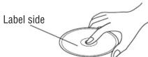
How to hold the disc
- Do not touch the underside of the disc.
- Do not scratch the disc.
- Do not bend the disc.
- When not in use, keep the disc in the case.
Do not use irregularly shaped discs.

Do not leave discs on the following places:
- Direct sunlight
- Near car heaters ● Dirty, dusty and damp areas
- Seats and dashboards
Disc cleaning
Use a dry, soft cloth to wipe from the center outward.


Do not attach any seals or labels to your discs.
Do not write anything on the disc label with a pointed pen or hard-point pen.
CQ-C5400/5300/5100W
Notes on CD-Rs/RWs
- You may have trouble playing back some CD-R/RW discs recorded on CD recorders (CD-R/RW drives), either due to their recording characteristics or dirt, fingerprints, scratches, etc. on the disc surface.
- CD-R/RW discs are less resistant to high temperatures and high humidity than ordinary music CDs. Leaving them inside a car for extended periods may damage them and make playback impossible.
- Some CD-R/RWs cannot be played back successfully due to incompatibility among writing software, a CD recorder (CD-R/RW drive) and the discs.
- This player cannot play the CD-R/RW discs if the session is not closed.
- This player cannot play the CD-R/RW discs which contain other than CD-DA (or MP3/WMA data CQ-C5400W [CQ-C5300W]).
- Be sure to observe the instructions of CD-R/RW disc for handling it.
Anti-Theft System
This unit is equipped with a removable face plate. Removing this face plate makes the unit totally inoperable.
Caution:
- This face plate is not waterproof. Do not expose it to water or excessive moisture.
- Do not remove the face plate while driving your car.
- Do not place the face plate on the dashboard or nearby areas where the temperature rises to high level.
- Do not touch the contacts on the face plate or on the main unit, since this may result in poor electrical contacts.
Remove the Removable Face Plate
① Switch off the power of the unit (page 24). ② Press [icon] (release) to remove the removable face plate. (The face plate disengages with a click when it is removed.)
![Menu, Tube, Bi-Rand, Faner, Deep. Contact [ ] (Release)](/content/2026/06/1328344/images/47db632250fe01a2f7afd7edfeae0ec8e90dfd4c5dab5bc5733e13768a5e5483.jpg)
Note:
- Be absolutely sure to turn off the main unit's power before removing the removable face plate.
- Do not install or remove the removable face plate while it is moving.
③ Gently press the bottom of the case and open the cover. Place the face plate into the case and take it with you when you leave the car.

- If dirt or other foreign substances get on the contacts, wipe them off with a clean and dry cloth.
- To avoid damaging the face plate, do not push it down or place objects on it while it is open.
- The front panel will automatically close about 5 seconds after [ ] (release) is pressed while the front panel is tilted or open, so take care to ensure that your fingers will not be pinched by the closing panel.
Install Removable Face Plate
① Slide the left side of the removable face plate in place. ② Press the right end of removable face plate until "click" is heard.

Security Indicator
The security indicator blinks when the face plate is removed from the unit.
This function is activated when the security function is on (page 42). Security indicator

Panel Removal Alarm
This alarm sounds to warn you not to forget to remove the panel before leaving your car.
This function is activated when the security function is on (page 42).
CQ-C5400/5300/5100W
Installation Guide

WARNING
This installation information is designed for experienced installers and is not intended for non-technical individuals. It does not contain warnings or cautions of potential dangers involved in attempting to install this product.
Any attempt to install this product in a motor car by anyone other than a qualified installer could cause damage to the electrical system and could result in serious personal injury or death.
If your car is equipped with air bags and/or anti-theft systems specific procedures may be required for connection and disconnection of the battery to install this product.
Before attempting installation of this electronic component contact your car dealer or manufacturer to determine the required procedure and strictly follow their instructions.
FAILURE TO FOLLOW THE PROCEDURE MAY RESULT IN THE UNINTENDED DEPLOYMENT OF AIR BAGS OR ACTIVATION OF THE ANTI-THEFT SYSTEM RESULTING IN DAMAGE TO THE VEHICLE AND PERSONAL INJURY.
Caution:
- This unit operates with a 12 V DC negative ground auto battery system only. Do not attempt to use it in any other system. Doing so could cause serious damage.
Installation Hardware
| No. | Item Diagram Q'ty | ||
| 1 | Mounting collar 1 | ||
| 2 | Hex. nut (5 mm φ ) | 1 | |
| 3 | Rear support strap 1 | ||
| 4 | Tapping screw(5 mm φ ×16 mm) | 1 | |
| 5 | Mounting bolt(5 mm φ ) | 1 | |
| 6 | Power connector 1 | ||
| 7 | Trim plate 1 | ||
| 8 | Lock cancel plate 2 |
Required Tools
You'll need a screwdriver, a 1.5 V AA battery, and the following:
12 V DC Test bulb
Electrical tape Side-cut


Overview
This product should be installed by a professional. However, if you plan to install this product yourself, your first step is to decide where to install it. The instructions in these pages will guide you through the remaining steps:
(Please refer to the "WARNING" statement.)
- Identify and label the car wires.
- Connect the car wires to the wires of the power connector.
- Install the unit in the dashboard.
- Check the operation of the unit.
If you encounter problems, please consult your nearest professional installer.
Before you begin installation, look for the items which are packed with your unit.
- Panasonic Service Station List for Service Directory... Keep for future reference in case the product needs servicing.
- Installation Hardware... Needed for in-dash installation.
Dashboard Specifications
Thickness: Min. 4.75 mm, Max. 5.56 mm

Preparation
- We strongly recommend that you wear gloves during installation to protect yourself from injuries.
- When bending the mounting tabs of the mounting collar with a screwdriver, be careful not to injure your hands and fingers.
- Disconnect the cable from the negative ⊖ battery terminal (see caution below).
- The unit should be installed in a horizontal position with the front end up at a convenient angle, but not more than 30°.


Caution:
- If your car is equipped with air bags and/or anti-theft systems, specific procedures may be required for connection and disconnection of the battery to install this product.
- Before attempting installation of this electronic component, contact your car dealer or manufacturer to determine the required procedure and strictly follow their instructions.
- FAILURE TO FOLLOW THE PROCEDURE MAY RESULT IN THE UNINTENDED DEPLOYMENT OF AIR BAGS OR ACTIVATION OF THE ANTI-THEFT SYSTEM, RESULTING IN DAMAGE TO THE VEHICLE AND PERSONAL INJURY.
Note:
- Various settings that have been stored in the memory of on-board equipment (e.g., car navigation) may be lost if the battery terminals are disconnected.
Therefore, we recommend making a record of or backing up the settings before disconnecting the terminals.
After completing installation of the main unit, set the equipment again according to the record.
Dashboard Installation
Installation Opening
This unit can be installed in any dashboard having an opening as shown above. The dashboard should be 4.75 mm–5.56 mm thick in order to be able to support the unit.
CQ-C5400/5300/5100W
Installation Guide (continued)
Identify All Leads
The first step in installation is to identify all the car wires you'll use when hooking up your sound system.
As you identify each wire, we suggest that you label it using masking tape and a permanent marker. This will help avoid confusion when making connections later.
Note:
- Do not connect the power connector to the stereo unit until you have made all connections. If there are no plastic caps on the stereo hooking wires, insulate all exposed leads with electrical tape until you are ready to use them. Identify the leads in the following order.
Power Lead
If your car has a radio or is pre-wired for one:
Cut the connector wires one at a time from the plug (leaving the leads as long as possible) so that you can work with individual leads.


Turn the ignition on to the accessory position, and ground one lead of the test bulb to the chassis.
Touch the other lead of the test bulb to each of the exposed wires from the cut radio connector plug. Touch one wire at a time until you find the outlet that causes the test bulb to light.
Now turn the ignition off and then on. If the bulb also turns off and on, that outlet is the car power lead.
If your car is not wired for an audio unit: Go to the fuse block and find the fuse port for radio (RADIO), accessory (ACC), or ignition (IGN).
Battery Lead
If your stereo unit has a yellow lead, you will need to locate the car's battery lead. Otherwise you may ignore this procedure. (The yellow battery lead provides continuous power to maintain a clock, memory storage, or other function.)
If your car has a radio or is pre-wired for one: With the ignition and headlights off, identify the car battery lead by grounding one lead of the test bulb to the chassis and checking the remaining exposed wires from the cut radio connector plug.
If your car is not wired for an audio unit: Go to the fuse block and find the fuse port for the battery, usually marked BAT.
Speakers
Identify the car speaker leads. There are two leads for each speaker which are usually color coded. A handy way to identify the speaker leads and the speaker they are connected with is to test the leads using a 1.5 V AA battery as follows.
Hold one lead against one pole of the battery and stroke the other lead across the other pole. You will hear a scraping sound in one of the speakers if you are holding a speaker lead.
If not, keep testing different lead combinations until you have located all the speaker leads. When you label them, include the speaker location for each.
Antenna Motor
If your car is equipped with an automatic power antenna, identify the car motor antenna lead by connecting one bulb tester lead to the car battery lead and touching the remaining exposed wires from the cut radio connector plug one at a time. You will hear the antenna motor activate when you touch the correct wire.
Antenna
The antenna lead is a thick, black wire with a metal plug at the end.
Connect All Leads
Now that you have identified all the wires in the car, you are ready to begin connecting them to the stereo unit wires. The wiring diagram (page 58) shows the proper connections and color coding of the leads.
We strongly recommend that you test the unit before making a final installation.
You can set the unit on the floor and make temporary connections to test the unit. Use electrical tape to cover all exposed wires.
Important:
- Connect the red power lead last, after you have made and insulated all other connections.
Ground
Connect the black ground lead of the power connector to the metal car chassis.
Speakers
Connect the speaker wires. See the wiring diagram (page 58) for the proper hookups. Follow the diagram carefully to avoid damaging the speakers and the stereo unit.
The speakers used must be able to handle more than 50 W of audio power. If using an optional audio amplifier, the speakers should be able to handle the maximum amplifier output power. Speakers with low input ratings can be damaged. Speaker impedance should measure 4–8 Ω, which is typically marked on most speakers. Lower or higher impedance speakers will affect output and can cause both speaker and stereo unit damage.
Motor Antenna
Connect the car motor antenna lead to the blue motor antenna relay control lead.
(Do not confuse the antenna lead with blue/white stripe lead for a power amplifier.)
Battery
Connect the yellow battery lead to the correct radio wire or to the battery fuse port on the fuse block.
Antenna
Connect the antenna by plugging the antenna lead into the antenna receptacle.
Equipment
Connect any optional equipment such as an amplifier, according to the instructions furnished with the equipment. Leave about 30 cm of distance between the speaker leads/amplifier unit and the antenna/antenna extension cord. Read the operating and installation instructions of any equipment you will connect to this unit.
Power
Connect the red power lead to the correct car radio wire or to the appropriate fuse port on the fuse block.
If the stereo unit functions properly with all these connections made, disconnect the wires and proceed to the final installation.
Final Installation
Lead Connections
Connect all wires, making sure that each connection is insulated and secure. Bundle all loose wires and fasten them with tape so they will not fall down later. Now insert the stereo unit into the mounting collar.
Congratulations! After making a few final checks, you're ready to enjoy your new auto stereo system.
Final Checks
- Make sure that all wires are properly connected and insulated.
- Make sure that the stereo unit is securely held in the mounting collar.
- Turn on the ignition to check the unit for proper operation.
If you have difficulties, consult your nearest authorized professional installer for assistance.
Installation Guide (continued)
Installation Procedures
First complete the electrical connections, and then check them for correctness (page 58).
Remove the mounting collar ① and the trim plate ⑦ from the main unit temporarily, which are already mounted at shipment.
⑥ Power connector
Mounting springs (※)
2
4
A
1
1
1
Therefore, m = 3/11
2

Engage the mounting springs (※) in the mounting holes of the mounting collar ① firmly.
The included mounting collar ① is designed specifically for this unit. Do not use it to attach any other model.
1. Insert mounting collar ① into the dashboard, and bend the mounting tabs out with a screwdriver.
The tabs to be bent vary depending on the car. To securely install the unit, fully bend a number of the tabs so that there is no rattling.
Example:

Secure the rear of the unit.
After fixing mounting bolt ⑤ and power connector ⑥, fix the rear of the unit to the car body by either method (a) or (b) shown below.
3 Insert trim plate ⑦.
4 After installation, reconnect the negative ⊖ battery terminal.


(b) Using the rubber cushion (option)
Rubber cushion (option) Rear support bracket (provided on the car)

CQ-C5400/5300/5100W
Remove the Unit
Switch off the power of the unit.
1 Remove the removable face plate (page 51).
2 Remove the trim plate ⑦ with a screwdriver.
3 Insert the lock cancel plates ⑧ along the grooves on both sides of the main unit until “click” is heard.
② Pull out the unit while pushing the plates further inside.
4 Remove the unit pulling with both hands.


CQ-C5400/5300/5100W

- HOW TO HOLD THE DISC
- DO NOT LEAVE DISCS ON THE FOLLOWING PLACES
- DISC CLEANING
- DO NOT ATTACH ANY SEALS OR LABELS TO YOUR DISCS
- NOTES ON CD-RS/RWS
- ANTI-THEFT SYSTEM
- CAUTION
- REMOVE THE REMOVABLE FACE PLATE
- NOTE
- INSTALL REMOVABLE FACE PLATE
- SECURITY INDICATOR
- PANEL REMOVAL ALARM
- INSTALLATION GUIDE
- WARNING
- REQUIRED TOOLS
- OVERVIEW
- DASHBOARD SPECIFICATIONS
- PREPARATION
- DASHBOARD INSTALLATION
- INSTALLATION GUIDE (CONTINUED)
- IDENTIFY ALL LEADS
- POWER LEAD
- BATTERY LEAD
- SPEAKERS
- ANTENNA MOTOR
- ANTENNA
- CONNECT ALL LEADS
- IMPORTANT
- GROUND
- MOTOR ANTENNA
- BATTERY
- EQUIPMENT
- POWER
- FINAL INSTALLATION
- LEAD CONNECTIONS
- FINAL CHECKS
- INSTALLATION PROCEDURES
- REMOVE THE UNIT
Brand : PANASONIC
Model : CQ-C5300W
Category : Car radio