
TP-75 - Waste press FRANKE - Free user manual and instructions
Find the device manual for free TP-75 FRANKE in PDF.


| Product Type | Waste Press (Compactor) |
| Brand | Franke |
| Model | TP-75 |
| Dimensions (H x W x D) | 400 mm x 300 mm x 500 mm |
| Weight | 12 kg |
| Material | Stainless steel, reinforced plastic |
| Power Source | Manual operation (hand lever) |
| Compaction Force | 1500 kg (approx.) |
| Waste Capacity | Up to 20 liters per cycle |
| Safety Features | Safety lock on handle, anti-jam mechanism |
| Installation | Freestanding or under-counter (with kit) |
| Operation | Pull lever to compact, release to eject block |
| Maintenance | Wipe with damp cloth, lubricate moving parts every 6 months |
| Spare Parts Available | Compaction plate, handle, foot pedal, springs |
| Repairability | Repairable by authorized service centers |
| Environmental | Reduces waste volume by up to 80% |
| Warranty | 2 years (parts and labor) |
| Certifications | CE, GS |
Frequently Asked Questions - TP-75 FRANKE
User questions about TP-75 FRANKE
0 question about this device. Answer the ones you know or ask your own.
Ask a new question about this device
Download the instructions for your Waste press in PDF format for free! Find your manual TP-75 - FRANKE and take your electronic device back in hand. On this page are published all the documents necessary for the use of your device. TP-75 by FRANKE.
USER MANUAL TP-75 FRANKE
FOOD WASTE DISPOSER FRANKE TURBO PLUS OWNERS GUIDE
Important - Read all instructions thoroughly
IMPORTANT SAFETY INSTRUCTIONS
Instructions pertaining to risk of fire, electric shock or injury to persons. Save these instructions.
WARNING - When using electrical appliances, basic precautions should always be followed, including the following:
- Read all instructions before using the appliance.
- To reduce the risk of injury, close supervision is necessary when an appliance is used near children.
- Do not put fingers or hands into a waste disposer while it is functioning.
- Turn the power switch to the off position before attempting to clear a jam or remove an object from the disposer.
- When attempting to loosen a jam in a waste disposer, use a long wooden utensil e.g. spoon.
- When attempting to remove objects from a disposer, use long-handled tongs or pliers.
- To reduce the risk of injury please note:
- this disposer is not for grinding hard materials, such as glass and metal;
- This disposer must be connected to the electric supply by means of either a power supply cord or insulated wires in a flexible conduit.
- When installing the disposer, care must be taken to ensure that the reset button of the overload protection device remains readily accessible.
- Additionally for continuous feed models:
- Care must be taken to ensure that the supply is disconnected by switching off the electric supply or by removing the plug from the socket-outlet before freeing a jammed rotor.
- When not operating the disposer, leave the stopper in place to reduce the risk of objects falling into the disposer.
- Do not operate disposer unless splash guard is in place.
9. For proper electrical earth instructions see the ELECTRICAL CONNECTION details of this manual.
- All installations should be carried out by a qualified electrician.
- The symbol ☒ on the product or on its packaging indicates that this product may not be treated as household waste. Instead, it shall be handed over to the applicable environmental collection point for the recycling of electrical and electronic equipment. For more detailed information about recycling of this product, please contact your local authority, your household waste disposal service or the shop where you purchased the product.
Please retain for future reference
1. OVERFLOW/APPLIANCE CONNECTIONS
For overflow or dishwasher connections, complete the following procedure. Alternatively go on to section 3.
1 Using a blunt instrument (steel punch or wooden dowel), knock out entire plug (see 1A). Do not use a screwdriver or sharp instrument. (When knockout plug falls into Disposer, you may remove it or grind it up when the disposer is used. This will not damage the disposer in any way, but may take some time to grind over the course of several uses).
2 Connect dishwasher hose (see 1B) using a hose clamp. Make sure all plumbing connections are tight and in accordance with all plumbing codes and ordinances. Run water and check for leaks.


WHEN YOU DO NOT WISH TO UTILISE THE AIR SWITCH
(e.g. if hard wiring the WDU to a standard electrical switch)
Follow the following procedure:
1 With the disposer mounted on the sink and the unit connected to the mains, turn ON the wall mounted switch.
2 Connect the air switch tube to the nipple on the underside of the unit.
3 If the disposer is OFF, depress air switch actuator to turn the disposer ON.
4 With the disposer ON pull air switch hose from disposer connection and discard air switch actuator and hose.
5 Turn the disposer OFF by turning off the switch, usually controlled by a wall mounted switch.
6 Operation of disposer is now controlled in a typical manner by the wall mounted switch.
FRANKE TURBO PLUS MODELS
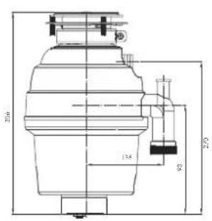
TP-50 Continuous Feed
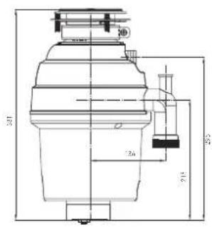
TP-75 Continuous Feed

TP-125 Continuous Feed

TP-125B Batch Feed
2a. INSTALLATION OF 3-BOLT MOUNTING ASSEMBLY
For TP-50, TP-75 and TP-125 models. Read completely before starting.
NB - Pay close attention to the order of mount assembly parts, as they have been correctly assembled by the factory. (See A and B.)
A Disassemble the mounting assembly, as it has been shipped, by turning the sink flange until the projections align with the notches in the mount ring and allow you to pull the sink flange up and out of the remaining mount assembly. Note the sequence of these parts as they are stacked and refer to A and B to identify each part. Unpack the 3 mount screws and screw them half way through the mount ring (notice "THIS SIDE UP" is imprinted on top of the mount ring). Next, stack the rubber gasket on top of the protector ring and sit them on top of the pointed ends of the mount screws. B Keep these assembled parts together and set aside. Before you connect the disposer to the mount assembly under the sink, you may want to practice engaging the groove of the cushion ring to the ridge at the bottom of the sink flange (see A and read Sec. 5). C Be sure your sink is clean. Pack the underside rim of the sink flange with plumber's putty (see C). Position the sink flange so it is centered and readable as you look into your sink. Push the sink flange firmly into the sink opening to make a good seal. DO NOT move or rotate the sink flange once seated or the seal may be broken. D Take the remaining portion of the mount assembly, as it was set aside and make sure that the rubber gasket is on top of the protector ring. From under the sink, while holding the sink flange firmly with one hand, line up the notches in the mount ring with the projections of the sink flange. Slide the mount assembly up onto the sink flange, past the projections and give the mount assembly a 1/4 turn, so that it will hang by itself (see D). E Tighten the 3 mounting screws evenly with a screwdriver (see E). DO NOT OVERTIGHTEN! Trim off excess putty.


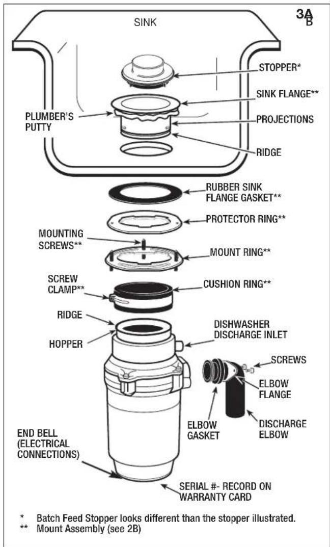


2b. INSTALLATION OF EZ MOUNT ASSEMBLY
For TP-125B models. Read completely before starting.
A Raise the mount ring towards the top of the sink flange. Remove cushion mount. Remove mount ring. You may want to practice installing the cushion mount at this point before you are under the sink.
See the 'IMPORTANT NOTICE: Cushion Mount Detail' below.
B Unscrew the support ring from the sink flange and remove the fibre gasket. You are now left with the sink flange and rubber gasket. C The rubber gasket is used instead of plumber's putty with stainless steel sinks. Other sinks will require silicone or plumber's putty. D If no caulking is used, insert the sink flange through the rubber gasket into the sink opening. Do not rotate the sink flange once it is seated. E If you use silicone instead of the gasket, form a ring around the underside of the sink flange (see C). Insert the flange into the sink opening, press down hard to squeeze out excess (see B). From under the sink, clean up excess flush with the bottom edge of the sink opening. F From underneath the sink, slip the fibre gasket onto the exposed sink flange. With arrows pointing up, screw the support ring onto the sink flange and hand tighten until the sink flange will not move.
At this point you may want to insert the stopper in the sink and fill with water to check the sink flange seal and ensure there are no leaks.
G Place the mount ring over the sink flange and hold it in place while installing the cushion mount (large side down) so the groove on the inside of the cushion mount fits over the lip on the sink flange (see D). H The disposer must be installed so that the reset button is easily accessible.
IMPORTANT NOTICE: Cushion Mount Detail
When the cushion mount is installed correctly, the lip of the sink flange fits into the groove of the inside of the cushion mount and the mount ring can be pulled downwards over the cushion mount and will be free to rotate. The bottom bead of the cushion mount acts as a gasket between the bottom of the sink flange and the top of the disposer (see F).
CONNECTION OF AIR SWITCH TO UNIT:
To install the button switch, unscrew the tightening nut and thread the plastic pipe and base of the button switch through the hole in the sink/worktop. Attach the nut and tighten it on the base of the button switch. Push the plastic pipe into the nipple on the base of the unit.


3. ELECTRICAL CONNECTIONS
DANGER - IMPROPER CONNECTION OF THE EQUIPMENT GROUNDING CONDUCTOR CAN RESULT IN A RISK OF ELECTRIC SHOCK. CHECK WITH A QUALIFIED ELECTRICIAN OR SERVICEMAN IF YOU ARE IN DOUBT AS TO WHETHER THE APPLIANCE IS PROPERLY GROUNDED. DO NOT MODIFY THE PLUG PROVIDED WITH THE APPLIANCE IF IT WILL NOT FIT THE OUTLET. HAVE A PROPER OUTLET INSTALLED BY A QUALIFIED ELECTRICIAN.
GROUNDING INSTRUCTIONS
For waste disposers equipped with a grounded plug-in power cord.
This appliance must be grounded. In the event of a malfunction or breakdown, grounding provides a path of least resistance for electric current to reduce the risk of electric shock. This appliance is equipped with a cord having an equipment-grounding conductor and a grounding plug.
The plug must be plugged into an appropriate outlet that is properly installed and grounded in accordance with all local codes and ordinances. If the supply cord is damaged, it must be replaced by the manufacturer, its service agent, or similarly qualified person in order to avoid a hazard.
4. ATTACHING DISCHARGE ELBOW
Assemble rubber gasket to waste elbow (see 4A).
Connect waste elbow to the disposer (see 4B), proceed to step 5 and then connect bottom of the elbow by tightening the slip nut (see 4C).
If you are connecting to a dishwasher, return to section 1B. If not, make sure all plumbing connections are tight and in accordance with all plumbing codes and ordinances. Run water and check for leaks.


5a. 3 BOLT MOUNT ASSEMBLY
For TP-50, TP-75 and TP-125 models.
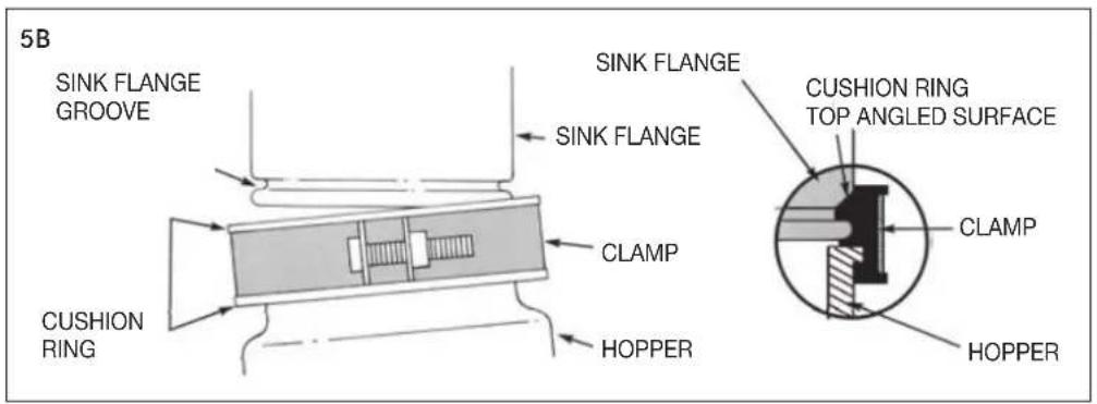
IMPORTANT PLEASE READ - DO NOT REMOVE CLAMP FROM CUSHION RING OR CUSHION RING FROM HOPPER. BOTH PARTS ARE FACTORY INSTALLED AND INSTALLATION READY
A Press firmly around the cushion ring to ensure it is engaged with the neck of the disposer. B Lubricate the top inside lip of the rubber cushion ring with a liquid soap. C Line up discharge elbow of disposer with trap under mounting assembly (see 5A). Guide disposer up and engage the GROOVE
of the cushion ring around the RIDGE at the bottom of the sink flange (see 5A & refer back to 2B). While still supporting the disposer, tighten the screw-clamp around cushion ring. The disposer will now hang by itself.
D If you need to turn the disposer make sure the sink flange does not turn. It will break the seal created when installed.

5b. EZ MOUNT ASSEMBLY
For TP-125B models.
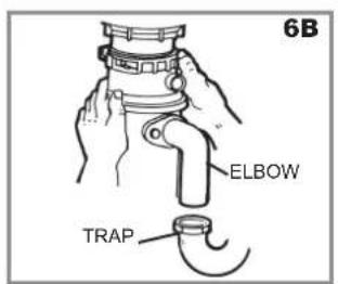
A Line up disposer under mounting assembly. Guide hopper projections into mount ring slots. Turn mount ring about 1/4" to right so that disposer is temporarily supported (see 6A). B Turn mount ring and disposer until disposer elbow lines up with trap (see 6B). C Turn mount ring to the right (counter-clockwise) until it locks up tight. Tap the mount ring ears with a hammer until the lock position is achieved. Hopper projections must be to extreme left of mounting slots (see 6C & 6D). D If mount ring is hard to turn, you may add a small amount of petroleum jelly or liquid soap to hopper projections. Run water and check for leaks.



6A. CONTINUOUS FEED OPERATING INSTRUCTIONS
The Anti-Jam Swivel Impellers make a clicking sound as they swing into place. This indicates normal operation.
A Remove sink stopper. Turn on a medium flow of cold water. B Turn switch to ON position; your motor is turning at full speed and ready to use. C Scrape in food waste. Down the drain go table scraps, peelings, rinds, seeds, pits, small bones and coffee grounds. To speed up food waste disposal, cut or break up large bones, rinds and cobs. Large bones and fibrous husks require
Considerable grinding time and are more easily thrown away with other trash. Do not be alarmed that the disposer slows down while grinding. The disposer is actually increasing torque (grinding power) and is operating under normal conditions.
D. Before turning disposer off, let water and disposer run for approximately 15 seconds after shredding stops. This ensures that all waste is thoroughly flushed through trap and drain.
E. It is not recommended to use hot water while running disposer. Cold water will keep waste and fats solid so disposer can flush away particles.
6B. BATCH FEED OPERATING INSTRUCTIONS
The Anti-Jam Swivel Impellers make a clicking sound as they swing into place. This indicates normal operation.
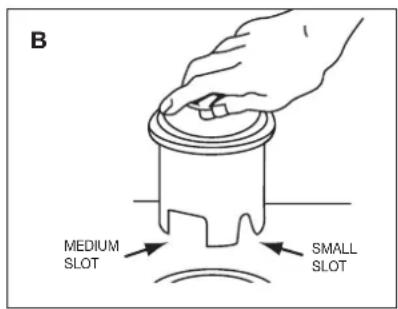
A. Remove sink stopper and turn on a medium flow of cold water. B. Scrape in food waste. Down the drain go table scraps, vegetable peelings, cobs, rinds, pits, bones and coffee grounds. (see A) C. Insert stopper to start disposer. (see B) One of the two small slots in stopper base must line up with switch plunger inside
the neck of the disposer. Push down firmly to turn the disposer on. Lift stopper to shut the disposer off.
D. Run disposer for 15 seconds after shredding stops. This ensures that all waste is thoroughly flushed through the drain.
E. To fill sink, insert stopper and align the largest slot with the switch plunger. (see C) Push down to seal sink without starting the disposer. When medium sized slot (see B) in stopper base is lined up with the switch plunger, water can drain, but tableware, etc., cannot be accidentally dropped into disposer.


7. TIPS FOR SUCCESSFUL OPERATION
A. Be sure disposer is empty before using your dishwasher so it may drain properly. B. You may want to leave the stopper in the drain when not in use to prevent utensils and foreign objects from falling into the disposer. C. Your disposer is ruggedly built to give you many years of trouble free service. It will handle all normal food wastes, but it will NOT grind or dispose of such items as plastic, tin cans, bottle caps, glass, china, leather, cloth, rubber, string, clam and oyster shells, aluminum foil or feathers.
8. TROUBLESHOOTING
Before seeking repair or replacement, we recommend that you review the following:
SAFETY NOTE: Before investigating you must disconnect the power supply. Depending on the installation this can be done by either removing the plug from the socket or for continuous feed models, switching the disposer control to OFF.
LOUD NOISES: (Other than those during grinding of bones and fruit pits) These are usually caused by accidental entry of a spoon, bottle cap or other foreign object. To correct this, remove *splash guard and remove object with long handled tongs. Replace *splash guard.
UNIT DOES NOT START: With *splash guard removed, check to see if turntable will rotate freely using a wooden utensil. If turntable rotates freely, replace *splash guard and check reset button to see if it has been tripped. Reset button is red and located opposite discharge elbow, near the bottom (see 8A). Push button in until it clicks and remains depressed.
If reset button has not been tripped, check for shorted or broken wire connecting to disposer. Check electrical power switch, fuse box or circuit breaker. If wiring and electrical components are intact, the unit may have internal problems that require service or replacement.
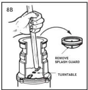
IF TURNTABLE DOES NOT ROTATE FREELY: Check for foreign object lodged between the turntable and grind ring. Dislodge object by rotating table with a wooden utensil and remove object (see 8B). If no foreign object is present, there may be internal problems.
CONNECTION OF AIR SWITCH TO UNIT: To connect the air switch the tube should be connect to the nipple on the underside of the unit by pushing it on firmly.
LEAKS: If the unit leaks at the top, it may be due to:
- Improper seating of sink flange (gasket choice, putty or tightening.)
- Support ring not tightened properly.
- Defective cushion mount.
If unit leaks at the waste elbow, leak may be due to improper tightening of elbow flange screws.

WARNING: Before resetting, disconnect the power supply - please see SAFETY NOTE above. The overload control prevents the motor from operating should overloading occur. This safety feature protects your house wiring and your disposer. When overloaded, the motor will stop automatically.
* Splash guard is not used with Batch Feed or 3-Bolt Mount units.
Franke UK Limited
West Park, MIOC
Styal Road
Manchester
M22 5WB
Phone +44 (0)161 436 6280
Fax +44 (0)161 436 2180
Email info.uk@franke.com
www.franke.co.uk
Service & Spares
UK Mainland & N. Ireland
Tel: 0844 371 0195
Fax: 0844 371 0198
franke@servevastdirect.co.uk
Republic of Ireland
Tel: +353 1 413 6481
Fax: +353 1 413 6489
kalserve@kal.ie
- FOOD WASTE DISPOSER FRANKE TURBO PLUS OWNERS GUIDE
- IMPORTANT SAFETY INSTRUCTIONS
- FOR PROPER ELECTRICAL EARTH INSTRUCTIONS SEE THE ELECTRICAL CONNECTION DETAILS OF THIS MANUAL
- OVERFLOW/APPLIANCE CONNECTIONS
- WHEN YOU DO NOT WISH TO UTILISE THE AIR SWITCH
- FRANKE TURBO PLUS MODELS
- A. INSTALLATION OF 3-BOLT MOUNTING ASSEMBLY
- B. INSTALLATION OF EZ MOUNT ASSEMBLY
- IMPORTANT NOTICE: CUSHION MOUNT DETAIL
- CONNECTION OF AIR SWITCH TO UNIT
- ELECTRICAL CONNECTIONS
- GROUNDING INSTRUCTIONS
- ATTACHING DISCHARGE ELBOW
- A. 3 BOLT MOUNT ASSEMBLY
- B. EZ MOUNT ASSEMBLY
- A. CONTINUOUS FEED OPERATING INSTRUCTIONS
- B. BATCH FEED OPERATING INSTRUCTIONS
- TIPS FOR SUCCESSFUL OPERATION
- TROUBLESHOOTING
Brand : FRANKE
Model : TP-75
Category : Waste press