DSB-071LH - Air conditioner DAEWOO - Free user manual and instructions
Find the device manual for free DSB-071LH DAEWOO in PDF.


| Product Type | Split Air Conditioner (Cooling & Heating) |
| Model | DSB-071LH |
| Cooling Capacity | 7,000 BTU/h (approx. 2.1 kW) |
| Heating Capacity | 7,500 BTU/h (approx. 2.2 kW) |
| Power Supply | 220-240 V, 50 Hz, Single Phase |
| Indoor Unit Dimensions (W x H x D) | 80 cm x 28 cm x 20 cm |
| Outdoor Unit Dimensions (W x H x D) | 70 cm x 50 cm x 25 cm |
| Indoor Unit Weight | 10 kg |
| Outdoor Unit Weight | 25 kg |
| Refrigerant Type | R32 |
| Noise Level (Indoor) | 30-40 dB(A) |
| Noise Level (Outdoor) | 55 dB(A) |
| Air Flow Rate (Cooling) | 400 m³/h |
| Energy Efficiency (SEER) | 6.1 (Class A++) |
| Filter Type | Washable Pre-Filter |
| Operating Temperature Range | -10°C to 45°C (Cooling), -10°C to 25°C (Heating) |
| Maintenance | Clean air filter every 2 weeks; annual professional check |
| Safety Features | Auto restart, anti-icing, overheat protection |
| Spare Parts Availability | Remote control, filters, fan motor, compressor |
| Warranty | 2 years (parts & labor) |
Frequently Asked Questions - DSB-071LH DAEWOO
User questions about DSB-071LH DAEWOO
0 question about this device. Answer the ones you know or ask your own.
Ask a new question about this device
Download the instructions for your Air conditioner in PDF format for free! Find your manual DSB-071LH - DAEWOO and take your electronic device back in hand. On this page are published all the documents necessary for the use of your device. DSB-071LH by DAEWOO.
USER MANUAL DSB-071LH DAEWOO
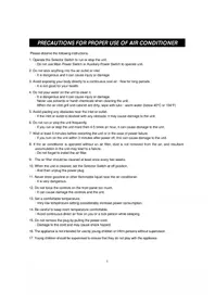
This air conditioner meets strict safety and operating standards. The installer of this unit must install or service this unit so it operates safely and efficiently.
IMPORTANT NOTES
- Adhere to all safety instructions and warnings throughout this manual.
- Read this manual carefully before installing or operating this unit to become familiar with its features and obtain the performance that will bring you continued enjoyment for many years.
- Follow each installation or repair step exactly as shown in the manual.
- Observe all local, state and national electric codes. Contact your local government for more information on electrical codes.

The lightning flash with arrowhead symbol, within an equilateral triangle is intended to alert the user to the presence of uninsulated dangerous voltage within the product's enclosure that may be of sufficient magnitude to constitute a risk of electric shock to persons.

The exclamation point within an equilateral triangle is intended to alert the user to the presence of important operating and maintenance (servicing) instructions in the literature accompanying the appliance.
Contact Installer if Necessary:
The installation instructions are for a experienced installer. If you are not an experienced installer, contact a local installer for help. If you require help with service, contact your certified dealer or Daewoo Electronics for additional instructions.
If Unit is Installed Improperly:
The manufacturer shall in no way be responsible for improper installation or maintenance service, including failure to follow the instructions in this manual.
WARNING:
- ELECTRICAL SHOCK CAN CAUSE SEVERE PERSONAL INJURY OR DEATH. ONLY A QUALIFIED, EXPERIENCED ELECTRICIAN/INSTALLER SHOULD ATTEMPT TO WIRE THIS SYSTEM.
- THE APPLIANCE IS NOT INTENDED FOR USE BY CHILDREN OR INFIRM PERSONS WITHOUT SUPERVISION
- YOUNG CHILDREN SHOULD BE SUPERVISED TO ENSURE THAT DO NOT PLAY WITH THE APPLIANCE
Precautions When Wiring:
- Do not plug in the unit until all connections (tubing, drain hose, mounting, etc.) have been made and double-checked.
- High voltages are present in this unit and are very dangerous. Please refer to these instructions and diagrams when wiring. Improper connections or inadequate grounding can cause accidental injury.
- This unit must be grounded in accordance with local electrical codes.
- Connect wires and pipes securely and tightly as loose connections/wiring may cause overheating at connections and a possible fire hazard.
Precautions When Transporting:
- When transporting the unit, be very careful and get help as the units are very heavy. Be careful of sharp edges on the units also.
Precautions When Installing:
- When installing in a ceiling or wall, make sure the ceiling/wall is strong enough to hold the unit's weight. A frame may be necessary for added support.
- When installing in a room, make sure the tubes are well insulated to protect the walls and furniture from sweating of the tubes.
- When installing in moist or uneven locations, make sure to use a raised level concrete pad or concrete blocks to provide a level, solid foundation for the outdoor unit; this prevents water damage and vibration.
- When installing in an area of high winds, make sure to securely anchor the outdoor unit down with bolts and a metal frame.
When Connecting Refrigerant Tubing:
- Keep all tubing as short as possible.
- Use the flare method for connecting tubing.
- Apply refrigerant lubricant to the matching surfaces of the flare and union tubes before connecting them, then tighten, making sure not to overtighten.
- Check the tubes carefully for leaks before starting the test run.
When Servicing:
- Make sure the power is off and the unit is unplugged before opening the unit to troubleshoot or repair electrical parts and wiring.
- Keep your fingers and clothing away from any moving parts.
- Clean up the sight after you finish, making sure no metal scraps and wiring are left in the unit.
- The Air conditioner shall be installed in accordance with the nationed wiring regulation.
CONTENTS
It is recommended that you read the Installation and Operating instructions fully before installing and/or operating this unit.
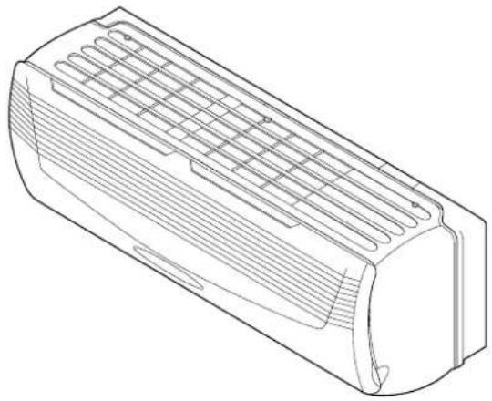
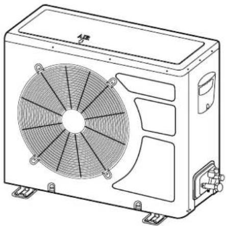
Safety Instructions....1
Contents 2
INSTALLATION SECTION
Basic Accessories ....3
Optional Accessories....4
Installation Diagram....5
Installation....6
Selecting a Site 6
Installing the Wall Bracket....6
Installing the Indoor/Outdoor Wire to
the Indoor Unit for AC Connection....7
Mounting the Indoor Unit....8
Preparing the Copper Tubing....9
Connecting Copper Tubes....9
Connecting the Drain Hose....10
Installing the Indoor/Outdoor Wire to
the Outdoor Unit for AC Connection....11
Taping up the Wire/Tubes/Hose....12
Applying Putty and Inserting Wall Cap ....12
Air Purging....13
Air Purging with Vacuum Pump....13
Test Run....15
Pump Down....15
OPERATING SECTION
Location of Controls 16
Indoor Unit....16
Outdoor Unit....16
Remote Controller....18
Remote Display....19
Operation....19
Connecting the AC Cord....19
Setting the Unit for Remote Operation....20
How to Install Batteries ....21
Celsius to Fahrenheit Conversion Chart....21
To Set the Unit to Auto Mode 22
To Operate Fan Only 22
To Set Unit to Cool Mode....22
To Set Unit to Heat Mode 23
To Set Unit to Dehumidifier Mode....23
To Select The Fan Direction 24
To Set Unit to High Power Cooling/Heating Mode.....24
To Set the On Timer Mode ....25
To Set the Off Timer Mode 25
To Set Unit to Sleep Mode....26
Emergency Operation....26
Changing/Cleaning the Air Filters 27
Cleaning the Indoor Cover 27
Care and Maintenance....28
Troubleshooting Guide....29
Specifications 30
INSTALLATION SECTION
BASIC ACCESSORIES
This Installation section explains how and where to connect this new air conditioner. Please read make sure all accessories are included as shown below and read manual thoroughly. This Installation section is provided to assist the person knowledgeable in air conditioner installation and should not be installed by anybody who is not thoroughly familiar with this type of installation. Please contact a professional installer if necessary.
ACCESSORIES SUPPLIED WITH THE UNIT:
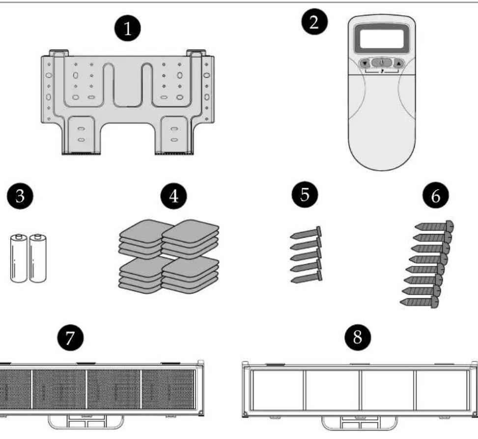
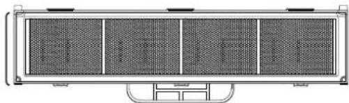
| No. Description Qty. | No. Description Qty. |
| 1 Wall Bracket 12 Remote Controller 13 Battery 24 Foot Cushion 4 | 5 Concrete Nails 56 Wall Bracket Screws 87 Deodorizing Filter Option Part 18 Electrostatic Filter 1 |
COPPER TUBING:
Copper tubing supplied is available at most dealers or A/C shops. Make sure the new copper tubing has the exact same specifications and diameter as the original copper tubing and is as short as possible.
OPTIONAL ACCESSORIES
ACCESSORIES NOT SUPPLIED WITH THE UNIT:
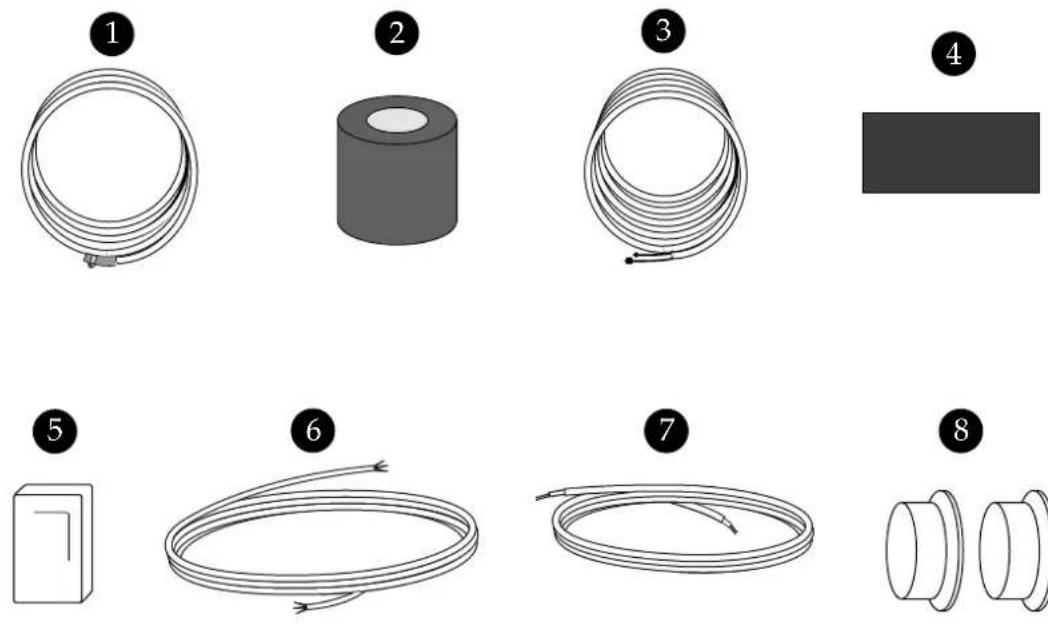
| No. | Description Part No. Qty Material Size | ||||
| 1 | Drain Hose Extension 3103200200 1 PVC | ID19.6 X 2m PVC Pipe | |||
| 2 | Tape 2TQ1008000 1 PVC 80W X 0.1T X 3.5m | ||||
| 3 | Copper Tubing Extension | 3100002600 | 1 | 1/2", 1/4" Copper Tube | |
| 4 | Insulator Plate | 3103301000 | 1 | F-US | 225 X 120 X 8T |
| 5 | Putty 22 | 21040001 1 | 80g | ||
| 6 | Connection Cord 31 | 02797200 1 | (1.5mm) | 2X 6m X 3P) | |
| 7 | Signal line Cord 31 | 02796360 1 | (1.5mm) | 2X 6m X 2P) | |
| 8 | Cap Wall 31 | 00900600 2 | P.P. | ||
| Complete Optional Accessories (1, 2, 3, 4, 5, 6, 7, 8) | 3100019000 1 | ||||
INSTALLATION DIAGRAM
Below is an overview for the connection of the the Indoor unit to the Outdoor unit. The pages following will give detailed instructions for full installation. Remember to read the complete Installation section and follow all the safety instructions fully when installing the Indoor and Outdoor units.
OVERVIEW
This appliance must be installed according to national power supply requirement.
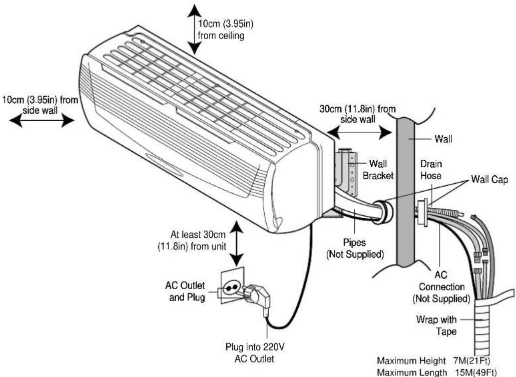
NOTES:
• After installation it must be possible for the user to disconnect the power supply plug.
- If the AC outlet is a 3-pronged type or other, have an electrician install a new outlet.
- Contact service man when replace the power cord set.
- The specification of AC connection is 1.5mm2X5PX6m .
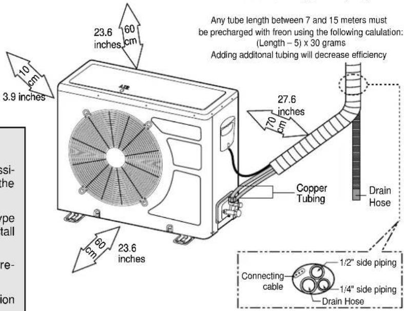
INSTALLATION
SELECTING A SITE:
INDOOR UNIT
- Do not install the unit in an area with direct sunlight, near heat sources (radiator, etc.), or an area where leakage of flammable gas may be expected.
- Select a position in the room, high on the wall, where the whole room can be uniformly cooled.
- Select a location that can hold the weight of the unit and where the copper tubing, drain hose and Indoor to Outdoor Wire have the shortest distance to the Outdoor unit.
- Make sure the Indoor unit is installed at least 10cm (3.95in) away from the top and left side wall and at least 30cm (11.8in) from AC outlet and right side wall (see Overview figure on previous page).
OUTDOOR UNIT
- Do not install the unit in an area near heat sources, exhaust fans, or an area where leakage of flammable gas may be expected.
- Do not install the unit in a humid, damp or uneven location.
- Select a location that is well ventilated.
- Leave enough room around the unit for air intake, exhaust and possible maintenance.
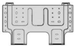
INSTALLING THE WALL BRACKET:
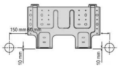
To install the wall bracket, follow the procedures below. One hole is required for the tubing and may be either on the left or right side.
- Determine the type of wall (sheetrock, concrete, etc.) and make sure it is strong enough to hold indoor unit. Select an approximate position for the unit, taking the required distances away from walls/AC outlet into consideration.
- Determine if the hole is to be made at the left or right hole location.

CAUTION
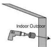
- Before making hole, make sure there are no studs, pipes, electrical wiring or conduit directly behind the area to be cut.
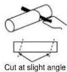
- Using drill with hole-cutting attachment or equivalent, cut a hole 65mm (2.56") in diameter. The hole should be made at a slight downward slant to the outdoor side. Measure the thickness from the inside to outside edges and cut a PVC pipe at a slight angle 1/4" shorter than the thickness of the wall and insert pipe in wall.
- For sheetrock, wooden or similar wall, measure down from the ceiling using a level or tape measure and attach the wall bracket to the wall using 4 screws. If you are not able to line up the holes with the beams, use toggle bolts. Make sure the wall bracket is even and flush against the wall.
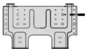
For Concrete, or similar type wall, make holes into the wall and insert concrete nails instead of screws.
INSTALLATION (CONTINUED)
INSTALLING THE INDOOR/OUTDOOR WIRE TO THE INDOOR UNIT FOR AC CONNECTION
The Indoor/Outdoor wire is used to supply AC from the Indoor unit to the Outdoor unit. To install the indoor/outdoor wire, follow the procedures below.
- Open the connection cover on the indoor unit to access the connection area.
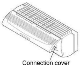
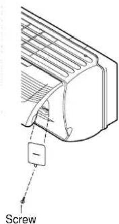
Remove the Connection Cover.
- Loosen one screw for fixing the Connection Cover.
- Loosen one screw at the Connection Cover.
- Remove the Connection Cover.
- Fish the indoor/outdoor wire from the rear of the indoor unit through the front of the unit.
For easier connection, make sure enough wire is pulled through the front.
Use the wire as shown below:
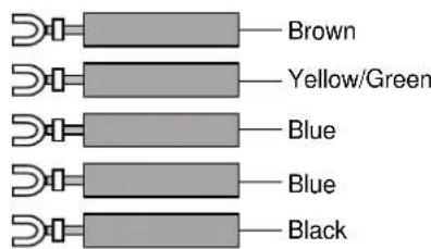
- To connect wires, loosen the screw in the Terminal Block and insert the correct wires like following figure. Connect the Brown wire to the "L" connection, Yellow/Green wire to the "connection", the Blue wire to "Y" connection, the Blue wire to "1" connection and the Black wire to "2" connection.
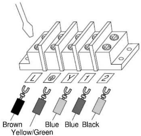
NOTES:
- This appliance must be installed according to National power supply requirement.
- If the supply cord is damaged, it must be replaced by the manufacturer or its service agent or a similarly qualified person in order to avoid a hazard.
- Make sure the Indoor unit's AC cord is not connected to AC power when connecting the indoor/outdoor wire.
- When connecting wires, make sure they are fully inserted and minimum copper wire is exposed. If they are not, shorting, overheating, no operation, etc. may occur.
- Be sure to comply with local codes on running a wire from the indoor to the outdoor unit.
INSTALLATION (CONTINUED)
- Connect the wires to the housing and terminals on the control board individually according to the outdoor unit connection.
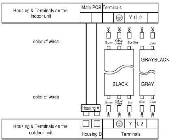
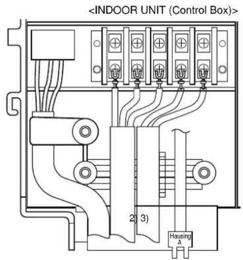
The used connection cable connected to indoor and outdoor unit must be ;
1) H07RN-F 3G1.5mm² (NOT INCLUDED)
2) H07RN-F 2G1.5mm² (NOT INCLUDED)
3) UL2464 AWG22 2G0.75mm² (INCLUDED IN SET)
MOUNTING THE INDOOR UNIT
The Indoor unit must be mounted before connecting the indoor/outdoor wire, drain hose and copper tubing. To mount, follow the procedures below:
- The tubing can be extended in 4 directions as shown below. No cutting is necessary for left/rear and right/rear tubing connections. If using left or right tubing connections, remove the plastic area with a hacksaw so pipes can go through.
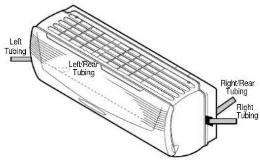
- Make sure the drain hose and copper tubing are wrapped with the rubber insulation. Using the tape, wrap the indoor/outdoor wire, copper tubing and drain hose together.

CAUTION:
- Make sure the Indoor unit's AC cord is not connected to AC power when performing these procedures.
- Be sure to comply with local codes on running a wire from the indoor to the outdoor unit.
- DO NOT LET THE INDOOR/OUTDOOR WIRE COME IN DIRECT CONTACT WITH THE TUBING OR HOSE!
INSTALLATION (CONTINUED)
- Shape the tubing so it can easily go through the hole in the wall. Push the indoor/outdoor wire, copper tubing and drain hose through the hole in the wall angling downward. Situate the indoor unit on the wall bracket by lifting the indoor unit slightly above the wall bracket and then down so it is securely locked in place.
PREPARING THE COPPER TUBING (NOT INCLUDED)
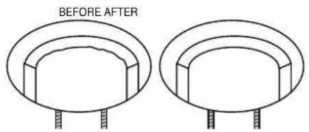
A copper tubing extension (not included) may need to be cut. If this is the case, it will also have to be deburred and flared as shown below:
- Cut the copper tube extension to the desired length with a tube cutter. It is highly recommended that 1 foot is added to the requested length. After cutting, deburring may be necessary (see below diagram). Perform this with a tube reamer.
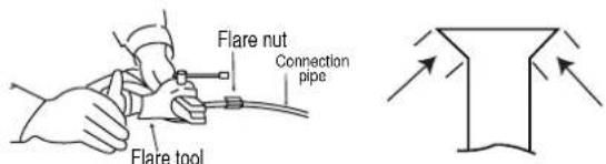
- Make a flare at the end of the copper tube with a flare tool. Make sure the inside surface and edges are smooth and the sides are uniform length.

CAUTION:
- When using the tube reamer, hold the tube downward and make sure no copper scraps fall into the tubing.
CONNECTING COPPER TUBES
To connect the copper tubes, follow the procedures below:
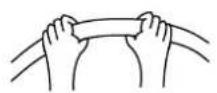
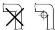
- Remove the flare nut stoppers from the inside unit. Determine the location of the copper tubing and where the bends will be. Gently bend the copper tubing, making sure to use big angles so no crimping will occur. Try to do this on the first try as repeated bending may break or crimp the tubing.
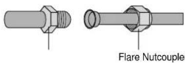
- Remove the plastic stoppers from the tubing. Connect the large and small copper tubing to the respective extension and rotate the flare nut with your finger until a smooth match is made. Make sure the copper extension has foam rubber (insulation) on it.
NOTE:
When removing the flare nut stopper from the inside unit, confirm "Ping", sounds because the mixed gas is charged in the inside unit,
INSTALLATION (CONTINUED)
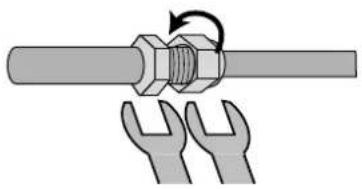
- Once a smooth match is made, tighten the flare nut using a wrench. Be very careful not to strip the threads or flare nut. Repeat this process for the small and large tubing. When tightening the flare nut, use another wrench to securely hold the coupler from twisting and possibly damaging the tubing.
-
Perform a leak test on all copper tube connections. To prevent heat loss and damage to walls from condensation, the copper tube connections coming from the wall must be insulated. Do this by wrapping foam rubber or equivalent around the connection approximately 8mm thick so no copper tubing is exposed.
-
Remove the flare nut stoppers from the outdoor unit's valves. Connect the larger copper tubing to the larger valve on the outdoor unit. Connect the smaller copper tubing to the smaller valve on the outdoor unit.
NOTES:
- As with all wiring and hookups on this unit, make sure the AC plug on the indoor unit is unplugged.
- Be very careful not to strip the threads or flare nut.
- When insulating the connections, use foam rubber or equivalent.
CONNECTING THE DRAIN HOSE
To connect the drain hose, follow the procedures below:
- Connect the drain hose extension to the drain hose coming from the indoor unit by loosing the clamp on the extension using a phillips screwdriver, attaching the hoses together and then tightening the clamp.
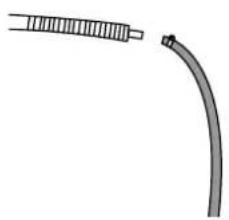
- Run the drain hose, slanted downward, outside. If the drain pipe is exposed indoors, make sure it is thoroughly insulated so condensation does not ruin walls or furniture or come in contact with the AC connection or extension. Also, do not crease or form a trap in the tubing.
INSTALLATION (CONTINUED)
INSTALLING THE INDOOR/OUTDOOR WIRE TO THE OUTDOOR UNIT FOR AC CONNECTION
The Indoor/Outdoor wire is used to supply AC from the Indoor unit to the Outdoor unit. To install the indoor/outdoor wire, follow the procedures below.
- Remove the screw holding on the connection cover. Remove the connection cover on the outdoor unit to access the connection area.
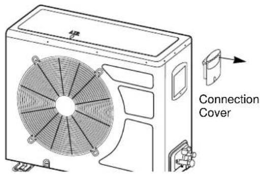
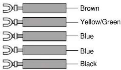
- Route the indoor/outdoor wire into the opening on the outdoor unit and through the wire holder. To connect to the wire holder, loosen the screw on the wire holder, insert the wires through, then tighten the screw.
Use the wire as shown below:
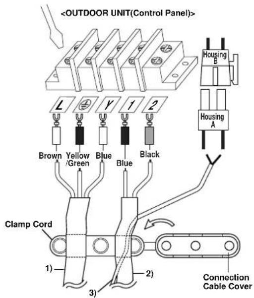
- Connect the wires to the housing and terminals on the Control board individually according to the outdoor unit Connection.
![graph TD A["Housing & Terminals on the indoor unit"] --> B["Main PCB"] B --> C["Terminals"] C --> D["Y 1-2"] D --> E["Black"] E --> F["BRIDGE"] F --> G["BRIDGE"] G --> H["BRIDGE"] H --> I["BRIDGE"] I --> J["BRIDGE"] J --> K["BRIDGE"] K --> L["BRIDGE"] L --> M["BRIDGE"] M --> N["BRIDGE"] N --> O["BRI…](/content/2026/06/1313564/images/a530e6f156c07e6be2ed95290335ce14bf028ce74918c7df37498092ec0683bf.jpg)
- To connect wires, loosen the screw in the Terminal Block and insert the correct wires like following figure. Connect the Brown wire to the "L" connection, Yellow/Green wire to the "connection", the Blue wire to "Y" connection, the Blue wire to "1" connection and the Black wire to "2" connection. Insert Housing "A" and Housing "B" to connection.
NOTES:
- Make sure the Indoor unit's AC cord is not connected to AC power when connecting the indoor/outdoor wire.
- When connecting wires, make sure they are fully inserted and minimum copper wire is exposed. If they are not, shorting, overheating, no operation, etc. may occur.
- Be sure to comply with local codes on running a wire from the indoor to the outdoor unit.
The used connection cable connected to indoor and outdoor unit must be ;
1) H07RN-F 3G1.5mm² (NOT INCLUDED)
2) H07RN-F 2G1.5mm² (NOT INCLUDED)
3) UL2464 AWG22 2G0.75mm² (INCLUDED IN SET)
INSTALLATION (CONTINUED)
TAPING UP THE WIRE/TUBES/HOSE
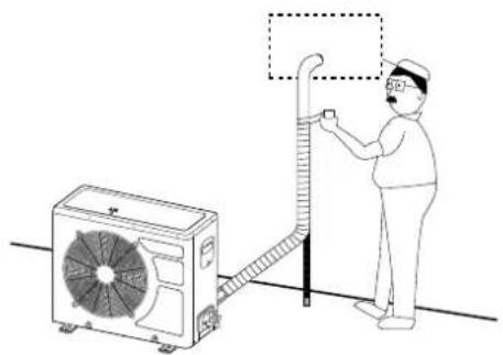
After running the wire, hose and tubing outside, tape them up as shown below to insulate.
- Tape the two copper tubes, drain hose (and the electrical wiring if local codes permit) together with the supplied tape. Make sure the electrical wiring does not come in direct contact with the copper tubing or drain hose. Approximately 1 foot outside the hole, let the drain hose out and separate from the copper tubing and wiring.
- Begin wrapping from the point the tubing comes out of the outdoor unit and continue to the hole in the wall. Leave no gaps or breaks and cover the entire length of the tubing. As you wrap, overlap the previous turn by half the width of the tape.
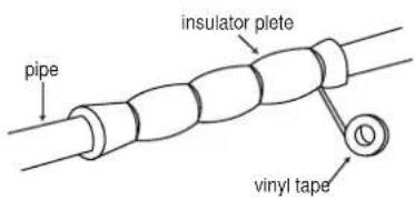
- Wrap the piping joints with the insulator plate and fasten it with vinyl tape.
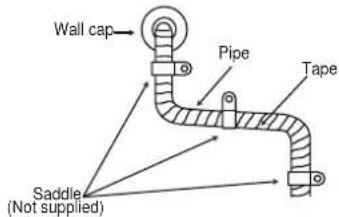
- After wrapping the connection pipe with tape, fasten it to the outside wall with saddles, etc.
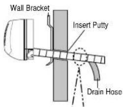
APPLYING PUTTY AND INSERTING WALL CAP
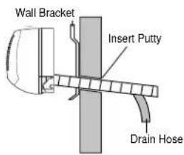
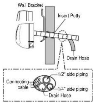
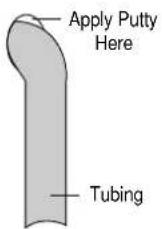
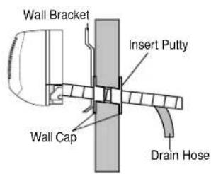
After running the wires and tubing outside, putty should be inserted around the opening on the outside to protect against rain, wind, etc. To apply putty, see below:
- Apply the putty to any area on the outside hole that air or rain can get into.
- After applying putty, insert the wall Cap at Indoor side and Outdoor side.
INSTALLATION (CONTINUED)
AIR PURGING
Air and moisture remaining in the refrigerant system may create adverse conditions as indicated below:
• pressure in the system rises
• operating current rises
• cooling efficiency drops
- moisture in the refrigerant circuit may freeze and block capillary tubing
• water may lead to corrosion of parts in the refrigerant system
Therefore, the indoor unit and tubing between the indoor and outdoor unit must be leak tested and evacuated to remove any noncondesables and moisture from the system.
AIR PURGING WITH VACUUM PUMP(TEST RUN)
Confirm each tube (narrow and wide tubes) between the indoor and outdoor units has been properly connected and all wiring for the test run has been completed. Remove the valve caps from the wide and narrow service valves on the outdoor unit. Note that both narrow and wide tube service valves on the outdoor unit are kept closed at this stage (shipping position).
Leak Test
- With the service valves on the outdoor unit remaining closed, remove the threaded cover on the wide tube service port. (Save for reuse.)
- Attach a manifold valve (with pressure gauge) and dry nitrogen gas cylinder to this service port with charge hoses.

CAUTION:
Be sure to use a manifold valve for air purging. If it is not available, use a stop valve for this purpose. The "Hi" knob of the manifold valve must always be kept closed.
3. Pressurize the system to no more than 150 P.S.I.G. with dry nitrogen gas and close the cylinder valve when the gauge reading reaches 150 P.S.I.G. Next, test for leaks with liquid soap.

CAUTION:
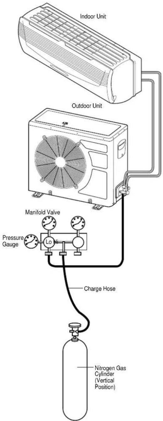
To avoid nitrogen entering the refrigerant system in a liquid state, the top of the nitrogen gas cylinder must be higher than its bottom when you pressurize the system. Usually, the cylinder is used in a vertical standing position.
- Do a leak test of all joints of the tubing (both indoor and outdoor) and both wide and narrow service valves. Bubbles indicate a leak. Be sure to wipe off the soap with a clean cloth.
- After the system is found to be free of leaks, relieve the nitrogen pressure by loosening the charge hose connector at the nitrogen cylinder. When the system pressure is reduced to normal, disconnect the hose from the cylinder.
INSTALLATION (CONTINUED)
Evacuation
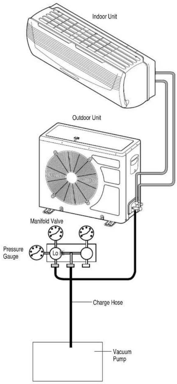
- Attach the charge hose end described in the leak test area to a vacuum pump to evacuate the tubing and indoor unit. Confirm the "Lo" knob of the manifold valve is open. Then, run the vacuum pump. The operation time for evacuation varies with the tubing length and capacity of the pump. The following table shows the amount of time for evacuation:
| Required time for evacuation when 30 gal/h vacuum pump is used | |
| If tubing length is less than 33 ft. (10 m) | If tubing length is longer than 33 ft. (10 m) |
| 10 min. or more | 15 min. or more |
- When the desired vacuum is reached, close the "Lo" knob of the manifold valve and stop the vacuum pump.
Finishing the job
- With a hex wrench, turn the narrow tube service valve stem counter-clockwise to fully open the valve.
- Turn the wide tube service valve stem counter-clockwise to fully open the valve.

CAUTION:
To avoid gas from leaking when removing the charge hose, make sure the wide tube service valve is fully open and turned all the way out.
- Loosen the charge hose connected to the wide tube service port slightly to release the pressure, then remove the hose.
- Replace the threaded cover on the wide tube service port and fasten it securely. This process is very important to prevent gas from leaking from the system.
- Replace the valve caps at both wide and narrow service valves and fasten them securely.
This completes air purging with a vacuum pump. The air conditioner is now ready to test run.
INSTALLATION (CONTINUED)
TEST RUN
Check that all tubing and wiring have been completed correctly. Check again that the wide and narrow tube service valves are fully opened. Turn on the power and run the system.
Service Valve Construction
- Valve Position Closed
The valve systems of both the wide and narrow tubes are turned all the way in. The unit is shipped from the factory in this position and it is also used for Pump Down and Air Purging.
• Valve Position Fully Open
The valve stems of both the wide and narrow tubes are turned all the way out. This is normal operating and Test Run position.
• Valve Position Half Open
With the narrow tube valve stem is turned to the halfway-down position. This position is used for pressure measurement and gas charging.

CAUTION:
When opening or closing the service valve stem, be sure to use a hex wrench.
PUMP DOWN
Pump Down means collecting all refrigerant in the outdoor unit without loss in refrigerant gas.
This is performed when the unit is to be relocated or the refrigerant circuit is serviced.

CAUTION:
Be sure to perform Pump Down procedure with the unit cooling mode.
Pump Down Procedure
- Connect a low-pressure gauge manifold hose to the charge port on the wide tube service valve.
- Open the wide tube service valve halfway and purge the air from the manifold hose using the refrigerant gas.
- Close the narrow tube service valve (all the way in).
- Turn on the unit's operating switch and start the cooling operation.
- When the low-pressure gauge reading becomes 1 to 0.5kg/cm2 (14.2 to 7.1 psi), fully close the wide tube valve stem and then quickly turn off the unit. At that time, Pump Down has been completed and all refrigerant gas will have been collected in the outdoor unit.
OPERATING SECTION
LOCATION OF CONTROLS
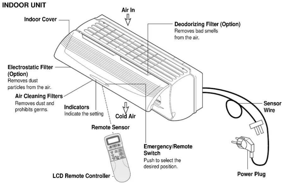
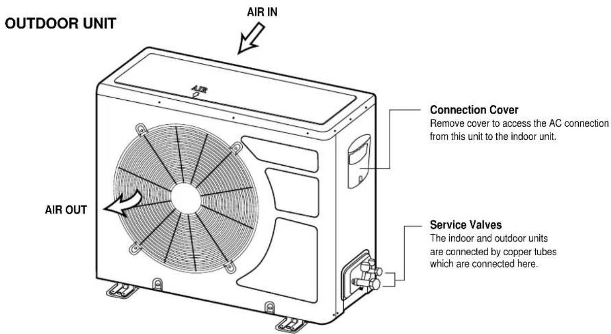
LOCATION OF CONTROLS
INDOOR UNIT
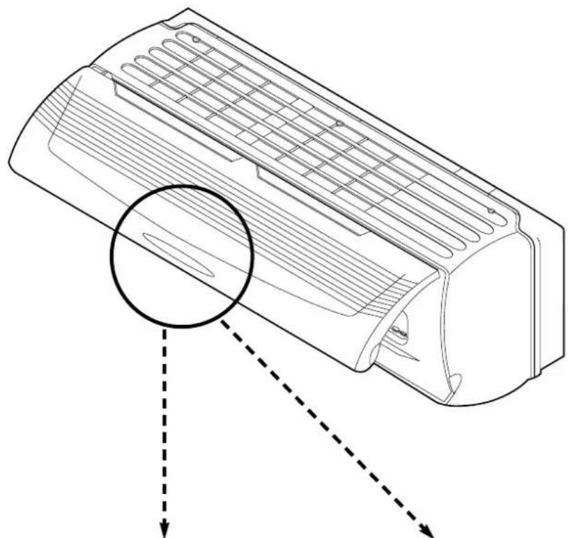
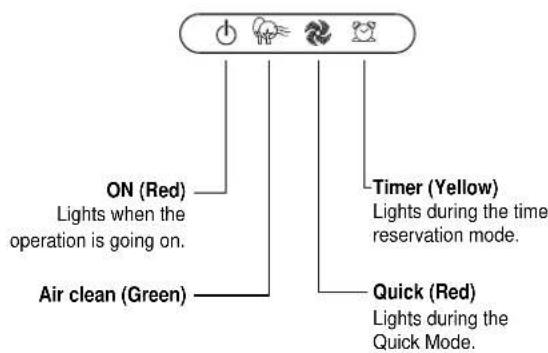
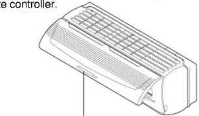
Indoor Unit Display Sw……anel
■ Remote Control Signal Receiver
This place is the part to receive the signal if it receive the signal, you can hear the signal "beep. beep".
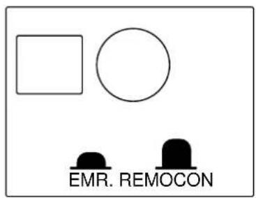
■ There is a switch panel at inside of Front Panel. At the time of operating, open the Front Panel.
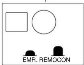
Emergency switch can be used when the remote controller is lost or Testing.
Remote switch is usually used by remote controller.
LOCATION OF CONTROLS (CONTINUED)
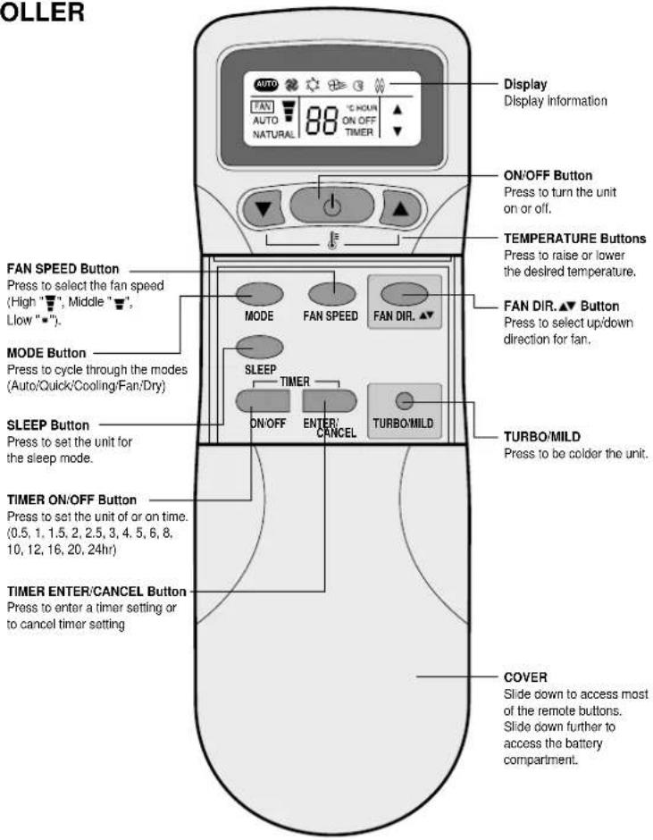
REMOTE CONTROLLER
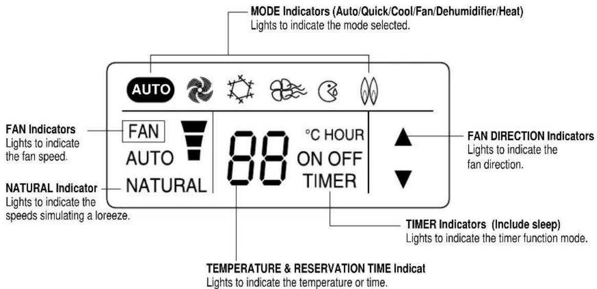
REMOTE DISPLAY
OPERATION
CONNECTING THE AC CORD
The outdoor unit is connected to the indoor unit through the AC connecting wire or connection cord. To connect the indoor unit to AC, follow the procedures below:
- Insert the attached AC plug into a pronged 220V AC outlet.
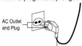
Plug into 220V AC Outlet.
NOTES:
- Never connect the AC line cord plug to other than the specified voltage (220V).
- Use the attached power cord only.
- The new air conditioner system should be on it's own 220V circuit. Contact your local electrical installer for installation.
After the unit is fully connected and plugged in, it can be turned on. To turn the unit on and set it for remote operation, follow the procedures below:
- Open the indoor unit's cover and make sure the EMERGENCY/REMOTE switch is set to the REMOTE position; this will allow the unit to operate with the remote controller.
EMERGENCY/REMOTE Switch
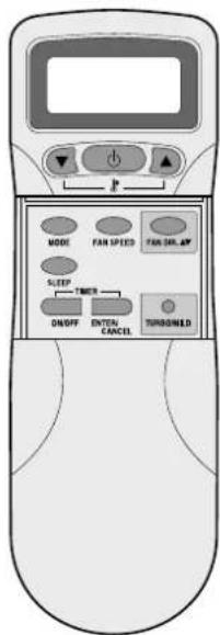
- Press the ON/OFF button on the remote controller to turn on the unit. The On LED will light on the indoor unit and "ON" will light in the remote display. To select the various modes and settings, read the following pages.
THREE MINUTE COMPRESSOR DELAY
- After turning the indoor unit on and setting it for air conditioner operation, the compressor (outdoor unit) will not come on for three minutes. This is a feature that will protect the compressor from damage due to quick start and stops.
OPERATION (CONTINUED)
HOW TO INSTALL BATTERIES
To install the batteries, follow the procedures below:
- Slide down the cover to access most of the remote buttons. Slide down further to access the battery compartment.
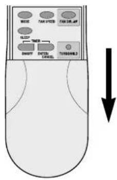
- Insert two "AAA" size Alkaline batteries following the polarity diagram below.
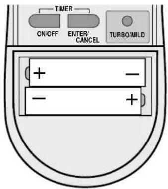
BATTERY PRECAUTIONS
The precautions below should be followed when using batteries in this device:
- Use only the size and type of batteries specified.
- Be sure to follow the correct polarity when installing the batteries as indicated in the battery compartment. Reversed batteries may cause damage to the device.
- Do not mix different types of batteries together (e.g. Alkaline and Carbon-zinc) or old batteries with fresh ones.
- If the device is not to be used for a long period of time, remove the batteries to prevent damage or injury from possible battery leakage.
- Do not try to recharge batteries not intended to be recharged; they can overheat and rupture. (Follow battery manufacturer's directions).
CELSIUS TO FAHRENHEIT CONVERSION CHART
| CELSIUS FAHRENHEIT | CELSIUS FAHRENHEIT |
| 18 64.4 | 26 78.8 |
| 19 66.2 | 27 80.6 |
| 20 68 | 28 82.4 |
| 21 69.8 | 29 84.2 |
| 22 71.6 | 30 86 |
| 23 73.4 | 31 87.8 |
| 24 75.2 | 32 89.6 |
| 25 77 |
NOTES:
- When operating the remote controller, make sure there are no obstructions between the remote controller and the remote sensor.
- After a while the display goes blank to conserve battery power. To check the settings, press the ON/OFF button once.
TO SET THE UNIT TO AUTO MODE
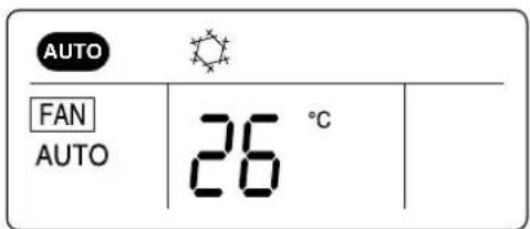
This unit will automatically operate the unit according to its surroundings while in the Auto mode. All you have to set is the desired temperature and it will control the fan, coolness and dehumidifier. Follow procedures below:
- Press the ON/OFF button on the remote control to turn the unit on; the On LED will light on the indoor unit and "ON" will light in the remote display.

-
Make sure the AUTO operator appears in the remote display. Using the TEMP. ▼ or ▲ buttons, set the desired temperature. The desired temperature can be changed up or down 1 degree from the actual room temperature. For temperature setting: 24\~28°C
-
Then the unit will automatically operate.
AUTO
FAN AUTO
SET UNIT TO QUICK MODE
To set this unit to cool at the highest power, follow the procedures below:
- Press the ON/OFF button on the remote control to turn the unit on; the On LED will light on the indoor unit and "ON" will light in the remote display.
- Press the MODE button until the Quick ("") indicator appears in the display.
- The unit will then start cooling the room at the highest power.
TO SET UNIT TO COOL MODE
To set the unit to cool the room to a desired temperature, follow the procedures below:
- Press the ON/OFF button on the remote control to turn the unit on; the On LED will light on the indoor unit and "ON" will light in the remote display.
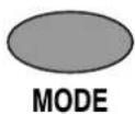
- Press the MODE button until the Cool indicator appears in the display.
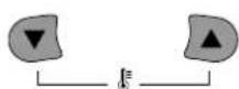
- Using the TEMP. ▼ or ▲ buttons, set the desired temperature. The desired temperature can be changed up to 32°C and down to 18°C.
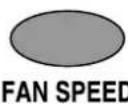
- To select the fan speed, press the FAN SPEED button until the desired speed appears in the display (see below).
FAN SPEEDS
"AUTO" The fan will automatically select the fan speed.
“The fan will operate on low speed.
“The fan will operate on medium speed.
“The fan will operate on high speed.
“NATURAL” The fan will randomly cycle through the speeds simulating a cool breeze.
TO OPERATE FAN ONLY
To operate only the fan so the unit will circulate the air, proceed as follows:
- Press the ON/OFF button on the remote control to turn the unit on; the On LED will light on the indoor unit and "ON" will light in the remote display.
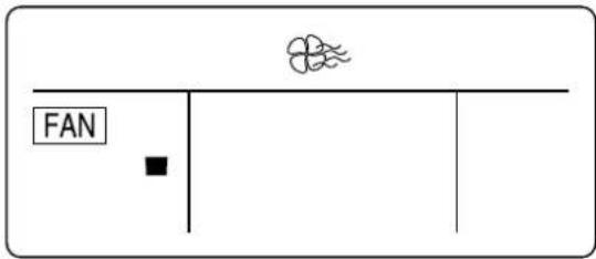
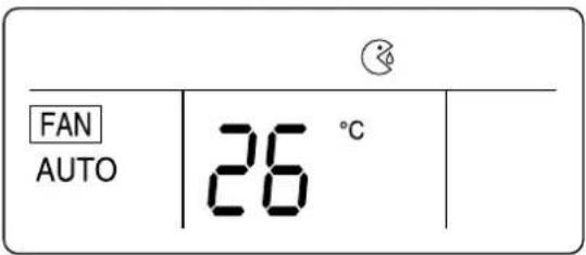
- Press the MODE button until the Fan indicator appears in the display. No allowance setting temperature
- To select a fan speed, press the FAN SPEED button until the desired speed appears in the display (see below).
FAN SPEEDS
“”The fan will operate on low speed.
“The fan will operate on medium speed.”
“The fan will operate on high speed.”
“NATURAL” The fan will randomly cycle through the speeds simulating a breeze.
NOTE:
- If "NATURAL" is selected, the NATURAL" indicator on the indoor unit will light.
TO SET UNIT TO DEHUMIDIFIER MODE
Select this mode when there is high humidity. To select, follow the procedures below.
- Press the ON/OFF button on the remote control to turn the unit on; the On LED will light on the indoor unit and "ON" will light in the remote display.
- Press the MODE button until the Dehumidifier indicator appears in the display.
- Using the TEMP. ▼ or ▲ buttons, set the desired temperature. The desired temperature can be changed up to 32°C and down to 18°C.
TO SET UNIT TO HEAT MODE
To set the unit to heat the room to a desired temperature, follow the procedures below:
- Press the ON/OFF button on the remote control to turn the unit on; the On LED will light on the indoor unit and "ON" will light in the remote display.
- Press the MODE button until the Heat indicator appears in the display. In the heat mode, the fan direction (UP, DOWN) is further downward than that in the cool mode for the good
- Using the TEMP. ▼ or ▲ buttons, set the desired temperature. The desired temperature can be changed up to 32°C and down to 18°C.
- To select the fan speed, press the FAN SPEED button until the desired speed appears in the display (see below).
NOTE:
When the heating orperation is started, hot air delivery might be delayed due to warm up period.
FAN AUTO

FAN SPEEDS
"AUTO" The fan will automatically select the fan speed.
“” The fan will operate on low speed.
“The fan will operate on medium speed.”
“The fan will operate on high speed.
“NATURAL” The fan will randomly cycle through the speeds simulating a cool breeze.
TO SELECT THE FAN DIRECTION
Regardless of the mode the unit is set for, the fan direction can be changed so it moves up and down, left and right or both. Follow procedures below to set fan direction.
- Press the ON/OFF button on the remote control to turn the unit on; the On LED will light on the indoor unit and "ON" will light in the remote display.
- Press the MODE button to select the desired mode.
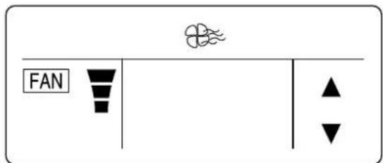
- Press the FAN DIR. button to select the fan direction. See chart below for detailed information on each of the three settings.
| FAN DIR. First Press The air will flow up and down. | |
| Second Press Normal air direction. |
TO SET THE ON TIMER MODE
This unit can be set to automatically turn on after a predetermined amount of hours (up to 24) in the order of 0.5, 1, 1.5, 2, 2.5, 3, 3.5, 4, 5, 6, 8, 10, 12, 16, 20, 24.
-
Press the ON/OFF button of timer on the remote control to set the on timer mode, "HOUR" and "ON" on the remote display will be displayed and "TIMER" will be flicked. When you increase to press "ON/OFF" you will get desired time. Then, if pressing "ENTER/CANCEL" button, ON TIMER Mode will be started. If you want to stop ON TIMER Mode, please press "ENTER/CANCEL" again.
-
While the unit is off, press the TIMER ON button; the display will light waiting input for the timer, but the actual unit will not turn on.
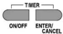
0.5 HOUR ON TIMER
- Repeatedly press the TIMER ON button until the desired hour that you want the unit to turn on appears on the display. For example, if it is 1:00 P.M. and you want the unit to turn on at 4:00 P.M., select
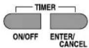
- Press the ENTER button to input the setting into memory; the unit will beep, the TIMER indicator will light on the unit and the TIMER indicator on the remote will light to indicate the unit is in the timer mode.
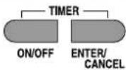
- Place the remote controller so it is facing the unit. When the desired hour is reached, the unit will turn on to the selected mode.
NOTE: Press the ENTER button within 5 seconds of selecting the desired time. If note than 5 seconds elapse, steps 3 and 4 must be repeated.
AUTO
FAN AUTO
26 ° C TIMER
TO SET THE OFF TIMER MODE
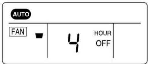
This unit can be set to automatically turn off after a predetermined amount of hours (up to 12) in the order of 0.5, 1, 1.5, 2, 2.5, 3, 3.5, 4, 4.5, 5, 5.5, 6, 6.5, 7, 7.5, 8, 8.5, 9, 9.5, 10, 11, 12.
-
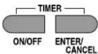
Press the ON/OFF button of timer on the remote control to set the off timer mode, "HOUR" and "OFF" on the remote display will be displayed and "TIMER" will be flicked. When you increase to press "ON/OFF" you will get desired time. Then, if pressing "ENTER/CANCEL" button, OFF TIMER Mode will be started. If you want to stop OFF TIMER Mode, please press "ENTER/CANCEL" again.
-
Press the TIMER OFF button once to enter the Timer screen.
AUTO
FAN AUTO
5 HOUR OFF TIMER
- Repeatedly press the TIMER OFF button until the desired hour that you want the unit to shut off appears on the display. For example, if it is 8:00 P.M. and you want the unit to turn off at 10:00 P.M.,
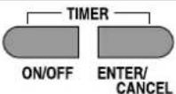
- Press the ENTER button to input the setting into memory; the unit will beep, the TIMER indicator will light on the unit and the TIMER indicator on the remote will light to indicate the unit is in the timer mode.
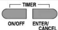
- Place the remote controller so it is facing the unit. When the desired hour is reached, the unit will turn off.
NOTE: Press the ENTER button within 5 seconds of selecting the desired time. If note than 5 seconds elapse, steps 3 and 4 must be repeated.
AUTO
FAN AUTO
26 ° C TIMER
TO SET UNIT TO SLEEP MODE
In the cooling operation; When you are going to sleep, select this feature and the unit will cool off the room to the desired temperature and then increase that temperature throughout the night.
In the heating operation; When you are going to sleep, select this feature and the unit will heat up the room to the desired temperature and then decrease that temperature throughout the night.
- Press the ON/OFF button on the remote control to turn the unit on; the On LED will light on the indoor unit and "ON" will light in the remote display.
- Press the MODE button to select the desired mode. Then, set the desired temperature using the TEMP. ▲ or ▲ buttons.
MODE
- Press the SLEEP button on the remote controller. The unit will then be in the sleep mode and will cool the room to the desired temperature. After a while the unit will increase the temperature again. This process will then repeat.
SLEEP
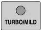
- Press the "TURBO/MILD" button to select powerful cooling if this button is selected one more time, it is become normal power. TURBO/MILD function is disable in actual heat operation (for example, heating operation in the Auto Mode or Heat Mode)
TO CANCEL SLEEP MODE:
To cancel sleep mode, press the SLEEP button again; the SLEEP indicator will disappear in the display.
EMERGENCY OPERATION
If the remote control is lost, broken or has no batteries, follow the procedures below:
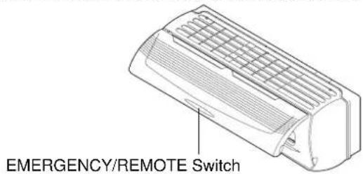
- Open the indoor unit's cover and make sure the EMERGENCY/REMOTE switch is set to the EMERGENCY position.
-
The unit will then turn on and depending on the room temperature, it will select the cool or dehumidifier, fan speed automatically.
-
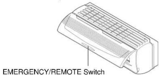
To turn the unit off, push the EMERGENCY/REMOTE switch to the REMOTE position.
CHANGING/CLEANING THE AIR FILTERS
To change or clean the two black air filters, follow the procedures below:
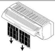
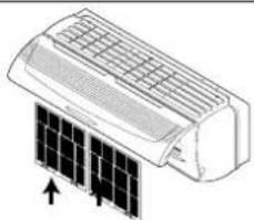
- Open the indoor unit's cover and remove both black air filters by bending them slightly backward and the lifting out.
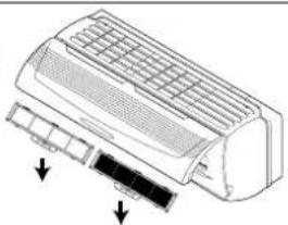
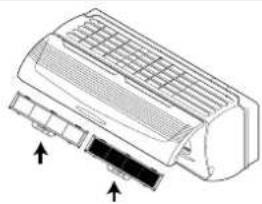
- Remove the two small filters (Deodorizing and Electrostatic) from the indoor unit. *This filters (Deodorizing and Electrostatic) are option.
- Examine the filters and determine if they need to be cleaned or replaced. To clean filters, use a vacuum and clean off dust. Use water and mild soap also if necessary.
NOTES:
-
The filters should be changed every 6 months. If in a climate with cold winters, once a year is adequate.
• After getting rid of vinyl in the filter (Deodorizing and Electrostatic), use it. -
Insert cleaned or new small filters (Deodorizing and Electrostatic) back into the unit.
- Insert cleaned or new black filters back into the unit.
CLEANING THE INDOOR COVER
To clean the indoor cover, follow the procedures below:
- Remove the left and right side to open the indoor cover upward by two hands.
NOTE: Please remove and insert the indoor cover by two hands.
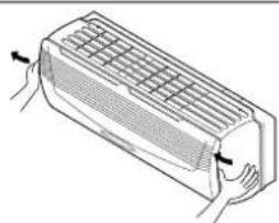
- Pushing forward the indoor cover.
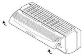
- Remove the indoor cover.
(Remove it when cleaning.)
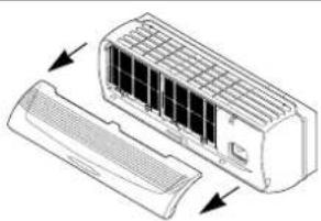
- Cleaning the indoor cover.
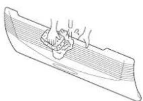
NOTES:
- Wipe the indoor cover with soft sponge or soft cloth.
- When cleaning up it in the state of opening the indoor cover, wipe it with soft cloth.
• After drying it completely in the shade, assemble it.
• If you do not so, it may cause a trouble. - Reassemble the indoor cover is reverse process of assemble
CARE AND MAINTENANCE

WARNING
- Make sure the AC cord is unplugged and the unit is off before cleaning.
- Do not use water on the unit to clean it. This is a shock hazard and the unit can be damaged.
Clean the casing and front of the indoor unit with a vacuum brush or wipe with a clean damp cloth.
- NEVER USE Solvents, harsh chemicals or hot water to clean the unit.
- Some metal edges on the unit are sharp. Be careful when cleaning or handling.
- Internal parts in the outdoor unit may need cleaning or routine maintenance from time to time. Consult your local service center for more details.
AFTER THE SEASON:
- Operate the fan, then dry the indoor unit.
- Shut off the indoor unit and then unplug it from the wall.
- Clean the air filters.
- Cover the outdoor unit with the supplied cover; this is very important to protect this unit.
BEFORE THE SEASON:
• Make sure the air filters are clean.
- Make sure the inlet and outlet on the indoor and outdoor units are not blocked by obstructions.
- Make sure the unit is grounded. Consult a serviceman for help.
PRECAUTIONS:
- Do not use this unit for animal or plant storage.
• In a lightning or thunder storm, immediately unplug it from the wall.
TROUBLESHOOTING GUIDE
Before requesting service, please refer to the chart below for possible solutions:
| SYMPTOMS POSSIBLE CAUSE POSSIBLE SOLUTIONS | ||
| No power. Power failure. | Restore the power | |
| Line voltage too low. Contact electrician to install new outlet. | ||
| Unit is unplugged or not completely Insert plugged in. | plug all the way. | |
| Unit is off. Turn unit on. | ||
| Batteries in remote are weak or dead. Replace remote's batteries. | ||
| EMERGENCY/REMOTE Push EMERGENCY/REMOTE switch is not set to REMOTE. to REMOTE. | ||
| The compressor does When the unit is first plugged in Wait 3 minutes for the compressor (no cool air) will delay turn on for 3 minutes. | the unit to operate. | |
| If the unit is turned off and then Wait 3 minutes immediately back on, the compressor will delay for 3 minutes. | ||
| The air filter(s) is dirty or clogged. | ||
| Unit is located near a heat source (heater, stove, etc.) | ||
| A door or window is open. Shut door or window. | ||
| There is an obstacle in front of intake or indoor unit. | ||
| Thermostat is set too high. | ||
| Strange sounds occur. | During operation, especially after turning it on or off, refrigerant flows inside the unit. | This is normal. |
| Strange smells occur. | The fan is bringing out the smells of the carpet, walls, etc. | The smell should go away shortly. |
| No remote operation. | Batteries are weak, dead or inserted improperly. | Replace batteries. |
| Remote is out of range. | Move closer to unit. | |
| Remote not aimed at sensor. | Aim remote at sensor. | |
| There is an obstruction between unit and remote. | Remove obstruction. | |
SPECIFICATIONS
| MODELDSB-071LH | |||
| Function Cooling / Heating (Heat pump) | |||
| Power Supply AC 220 | -240V, 50Hz | ||
| Cooling Capacity (Heating) | 1,688 Kcal/h (1,764 Kcal/h) | ||
| Operating Current (Heating Mode) | 3.0 A (3.2 A) | ||
| Power Consumption (Heating Mode) | 676 W (693 W) | ||
| Indoor Unit Dimensions W 750 x H 240 x D | 174 mm | ||
| Outdoor Unit Dimensions W 654 x H 549 x D | D 256 mm | ||
| Net Weight | Indoor 7.0 kg | ||
| Outdoor 34 kg | |||
| Connection the piping | Type Flare | ||
| Gas 1/2" (12.7 mm) | |||
| Liquid 1/4" (6.35 mm) | |||
| Air Cleaning Anti-bacteria Filter, (Electrostatic Filter, Deodorizing Filter Option) | |||
| Operating Condition | Indoor side (Heating Mode) | min 21°C ~ max 32°C (min 15°C ~ max 27°C) | |
| Outdoor side (Heating Mode) | min 21°C ~ max 43°C (min -5°C ~ max 24°C) | ||
Design and specification are subject to change without notice for product improvement.
S/N:3103901701

- IMPORTANT NOTES
- CONTACT INSTALLER IF NECESSARY
- IF UNIT IS INSTALLED IMPROPERLY
- WARNING
- PRECAUTIONS WHEN WIRING
- PRECAUTIONS WHEN TRANSPORTING
- PRECAUTIONS WHEN INSTALLING
- WHEN CONNECTING REFRIGERANT TUBING
- WHEN SERVICING
- CONTENTS
- INSTALLATION SECTION
- OPERATING SECTION
- BASIC ACCESSORIES
- ACCESSORIES SUPPLIED WITH THE UNIT
- COPPER TUBING
- OPTIONAL ACCESSORIES
- ACCESSORIES NOT SUPPLIED WITH THE UNIT
- INSTALLATION DIAGRAM
- OVERVIEW
- NOTES
- INSTALLATION
- SELECTING A SITE
- INDOOR UNIT
- OUTDOOR UNIT
- INSTALLING THE WALL BRACKET
- CAUTION
- INSTALLATION (CONTINUED)
- INSTALLING THE INDOOR/OUTDOOR WIRE TO THE INDOOR UNIT FOR AC CONNECTION
- MOUNTING THE INDOOR UNIT
- PREPARING THE COPPER TUBING (NOT INCLUDED)
- CONNECTING COPPER TUBES
- NOTE
- CONNECTING THE DRAIN HOSE
- INSTALLING THE INDOOR/OUTDOOR WIRE TO THE OUTDOOR UNIT FOR AC CONNECTION
- TAPING UP THE WIRE/TUBES/HOSE
- APPLYING PUTTY AND INSERTING WALL CAP
- AIR PURGING
- AIR PURGING WITH VACUUM PUMP(TEST RUN)
- LEAK TEST
- EVACUATION
- FINISHING THE JOB
- TEST RUN
- SERVICE VALVE CONSTRUCTION
- VALVE POSITION CLOSED
- VALVE POSITION FULLY OPEN
- VALVE POSITION HALF OPEN
- PUMP DOWN
- PUMP DOWN PROCEDURE
- LOCATION OF CONTROLS
- INDOOR UNIT DISPLAY SW……ANEL
- REMOTE CONTROL SIGNAL RECEIVER
- THERE IS A SWITCH PANEL AT INSIDE OF FRONT PANEL. AT THE TIME OF OPERATING, OPEN THE FRONT PANEL
- LOCATION OF CONTROLS (CONTINUED)
- OPERATION
- CONNECTING THE AC CORD
- THREE MINUTE COMPRESSOR DELAY
- OPERATION (CONTINUED)
- HOW TO INSTALL BATTERIES
- BATTERY PRECAUTIONS
- CELSIUS TO FAHRENHEIT CONVERSION CHART
- TO SET THE UNIT TO AUTO MODE
- AUTO
- SET UNIT TO QUICK MODE
- TO SET UNIT TO COOL MODE
- FAN SPEEDS
- TO OPERATE FAN ONLY
- TO SET UNIT TO DEHUMIDIFIER MODE
- TO SET UNIT TO HEAT MODE
- TO SELECT THE FAN DIRECTION
- TO SET THE ON TIMER MODE
- TO SET THE OFF TIMER MODE
- TO SET UNIT TO SLEEP MODE
- TO CANCEL SLEEP MODE
- EMERGENCY OPERATION
- CHANGING/CLEANING THE AIR FILTERS
- CLEANING THE INDOOR COVER
- CARE AND MAINTENANCE
- AFTER THE SEASON
- BEFORE THE SEASON
- PRECAUTIONS
- TROUBLESHOOTING GUIDE
Brand : DAEWOO
Model : DSB-071LH
Category : Air conditioner