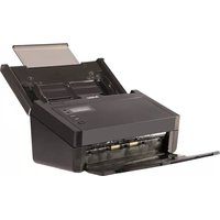
AD260 - Scanner AVISION - Free user manual and instructions
Find the device manual for free AD260 AVISION in PDF.


| Product Type | Document Scanner |
| Scanner Type | ADF (Automatic Document Feeder) + Flatbed |
| Scan Speed (Color / Grayscale / B&W) | Up to 60 ppm (simplex), 120 ipm (duplex) |
| Optical Resolution | 600 dpi |
| Document Size | Up to A4 (210 x 297 mm) |
| ADF Capacity | 80 sheets (80 gsm) |
| Duplex Scanning | Yes, one-pass duplex |
| Dimensions (W x D x H) | 430 x 310 x 200 mm |
| Weight | 4.5 kg |
| Power Supply | AC 100-240 V, 50/60 Hz |
| Power Consumption | 30 W (operating), <5 W (sleep) |
| Interface | USB 3.0 (compatible with USB 2.0) |
| Supported OS | Windows, macOS |
| Daily Duty Cycle | Up to 5,000 scans |
| Maintenance | Clean glass and ADF rollers with approved cleaning wipes |
| Safety Certifications | UL, CE, FCC |
| Spare Parts / Repairability | ADF roller kit, separation pad, replacement ADF module |
| Included Software | Avision Capture Tool, Twain driver, ISIS driver |
| Warranty | 1 year limited |
Frequently Asked Questions - AD260 AVISION
User questions about AD260 AVISION
0 question about this device. Answer the ones you know or ask your own.
Ask a new question about this device
Download the instructions for your Scanner in PDF format for free! Find your manual AD260 - AVISION and take your electronic device back in hand. On this page are published all the documents necessary for the use of your device. AD260 by AVISION.
USER MANUAL AD260 AVISION
natural_image
Line drawing of a printer with internal components and base mount (no text or symbols)Regulatory model: FL-1315B/FL-1314B
Avision Inc.
Trademarks
Microsoft is a U.S. registered trademark of Microsoft Corporation. Windows, Windows Vista, Windows 7, Windows 8, and Windows 10 are either registered trademarks or trademarks of Microsoft Corporation in the United States and/or other countries.
Energy Star ® is a registered trademark of the U.S. government. IBM, IBM PC are registered trademarks of International Business Machines Corp.
Other brands and product names herein are trademarks or registered trademarks of their respective holders.
Copyright
All rights reserved. No part of this publication may be reproduced, transmitted, transcribed, stored in a retrieval system, or translated into any language or computer language, in any form or by any means, electronic, mechanical, magnetic, optical, chemical, manual, or otherwise, without the prior written permission of Avision Inc.
Material scanned by this product may be protected by governmental laws and other regulations, such as copyright laws, the customer is solely responsible for complying with all such laws and regulations.
Warranty
The information contained in this document is subject to change without notice.
Avision makes no warranty of any kind with regard to this material, including, but not limited to, the implied warranties of fitness for a particular purpose.
Avision shall not be liable for errors contained herein or for incidental or consequential damages in connection with the furnishing, performance, or use of this material.
Federal Communications Commission (FCC) compliance information statement
Part 15
This equipment has been tested and found to comply with the limits for a Class B digital device, pursuant to Part 15 of the FCC Rules. These limits are designed to provide reasonable protection against harmful interference in a residential installation. This equipment generates, uses and can radiate radio frequency energy and, if not installed and used in accordance with the instructions, may cause harmful interference to radio communications.
However, there is no guarantee that interference will not occur in a particular installation. If this equipment does cause harmful interference to radio or television reception, which can be determined by turning the equipment off and on, the user is encouraged to try to correct the interference by one of the following measures:
- Reorient or relocate the receiving antenna.
- Increase the separation between the equipment and receiver.
- Connect the equipment into an outlet on a circuit different from that to which the receiver is connected.
- Consult the dealer or an experienced radio/TV technician for help.
This device complies with Part 15 of the FCC Rules. Operation is subject to the following two conditions: (1) This device may not cause harmful interference, and (2) this device must accept any interference received, including interference that may cause undesired operation.
CE
European Union Regulatory Notice
Products bearing the CE marking comply with the following EU Directives:
● Low Voltage Directive 2014/35/EC
● EMC Directive 2014/30/EC
- Restriction of the use of certain hazardous substances (RoHS) Directive 2011/65/EU
CE compliance of this product is valid if powered with the correct CE-marked AC adapter provide by Avision.
This product satisfies the Class B limits of EN55022, EN55024, safety requirements of EN 60950 and ROHS requirements of EN50581.
* This machine is certified as Class 1 LED product.
Disposal of Waste Equipment by Users in Private Union

This symbol on the product or on its packaging indicates that the product can not be disposed of with your other household waste. Instead it should be sent to appropriate facilities for recovery and recycling in an effort to protect human health and the environment. Fore more information about where you can drop off your waste equipment for recycling, please contact your local city office, your household waste disposal service or the shop where you purchased the product.

As an ENERGY STAR® Partner, Avision Inc. has determined that this product meets the ENERGY STAR guidelines for energy efficiency.
System Requirements
CPU: Intel ® Core TM 2 Duo or higher
Memory: 32 bit: 2 GB
64 bit: 4 GB
Optical Drive: DVD-ROM Drive
USB Port: USB port 3.0 (compatible with USB 2.0/1.1)
Compatible Microsoft Windows XP(SP3), Windows Vista,
Operating Windows 7, Windows 8 (32 bits/64 bits),
System: Windows 10 (32 bits/64 bits)
Product Safety Guide
Please clearly read all these instructions, and follow all instructions and warnings before installing and using the device.
The following indications are used in this document to obviate any chance of accident or damage to you and/or the device.
| WARNING | Indicates potentially hazardous situations, which if instructions are not followed, could result in death or serious injury. |
| CAUTION | Indicates a potentially hazardous situation which, if instructions are not followed, may result in minor or moderate injury or damage to property. |
WARNING
Use only the AC power adapter that came with your device. Using any other AC power adapter could cause fire, electrical shock, or injury.
Use only the AC power cord and USB cable that came with your device and avoid abrasions, cuts, fraying, crimping, and kinking. Using any other AC power cord and USB cable could cause fire, electrical shock, or injury.
Do not place objects on top of the AC power cord, and do not allow the AC power adapter or the AC power cord to be stepped on or run over.
Place the device and its AC power adapter near an electrical outlet where the AC power adapter can easily be unplugged.
If you use an extension cord with the device, make sure that the total ampere rating of the devices plugged into the extension cord does not exceed the cord's ampere rating.
Place the device close enough to the computer so that the interface cable can easily reach between the device and the computer.
Do not place or store the device or its AC power adapter:
- Outdoors
● Near excessive dirt or dust, water, or heat sources - In locations subject to shocks, vibrations, high temperature or humidity, direct sunlight, strong light sources, or rapid changes in temperature or humidity
Do not use the device with wet hands.
Never disassemble, modify, or attempt to repair the AC power adapter, device, or device option by yourself, except as specifically explained in the device's documentation. This could cause fire, electrical shock, or injury.
Do not insert objects into any opening, as they may touch dangerous voltage points or short-out components. Beware of electrical shock hazards.
Unplug the device and the AC power adapter, and refer servicing to qualified service personnel under the following conditions:
● The AC power adapter or plug is damaged.
- Liquid has entered the device or the AC power adapter.
- Object has entered the device or the AC power adapter.
- The device or the AC power adapter has been dropped, or the case has been damaged.
- The device or the AC power adapter does not operate normally (i.e. appearance of smoke, strange smell, odd noise, etc.), or exhibits a distinct change in performance
■ Unplug the device and the AC power adapter before cleaning.
CAUTION:
Do not locate the device on rackety or aslope tables. Do not locate the device on unstable surface. The device may fall down and this may result in injury.
Do not place heavy objects on the unit. It may cause unbalance and the device may fall down. This may result in injury.
- Store the AC Power cord/USB cable bundled out of the reach of children to avoid the risk of injury.
- Keep plastic bags bundled out of the reach of children to avoid the danger of suffocation.
If you are not going to use the device for a long period, unplug the AC power adapter from the electrical outlet.
1. Introduction
Congratulations on your purchase of the color sheet-fed image scanner. With this scanner, you can scan documents from the auto document feeder increase your productivity.
Before you install and operate the new scanner, please take a few minutes to read through this manual. It provides proper instructions for you to unpack, install, operate and maintain the scanner.
1.1 Package Items
The following figure indicates the package contents. Please check all the items against your checklist. If you do not receive all the items, please contact your authorized local dealer immediately.
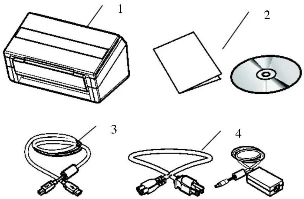
- Scanner Main Unit
- Quick Guide/ CD
- USB Cable
- Power Adapter & Power Cord
Note:
- Only use the AC adapter DA-48M24 by APD included in the machine. Using other AC adapters may damage the machine and void the warranty.
- Please unpack the packing carefully, and check the contents against the checklist. If any items are missing or damaged, please contact your dealer immediately.
- To access more service supports, visit www.avision.com to register your Avision's product.
1.2 Front View
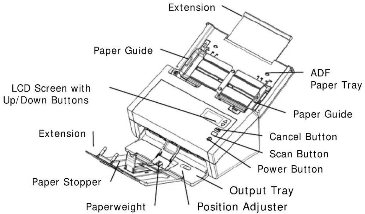
| Part Name | Function |
| Extension Can be | pulled out and adjusted to the size of the document being scanned. |
| ADF Paper Tray | Load the document onto this part when scanning document. |
| Paper Guides Adj | usts to the width of the documents to prevent skewing of the scanned pages. |
| Operation Panel | LCD screen:Shows a number indicating a scan-to destination via the Up/Down buttons.The Power Button:Press to turn on the power.The Scan Button:Press to start a scan.The Cancel Button:Press to cancel a scanning job during operation. |
| Output Tray Open | to collect the document after scanned. |
| Position Adjuster | Slide the adjuster inward to make the Output Tray in a flat position. |
| Extension | Pull it out. Documents are ejected from the ADF to the tray. |
| Paperweight | Used to hold down a stack of output paper. |
| Paper Stopper Adjusted | Adjust to the length of the documents to prevent them from falling apart. |
1.3 Rear View
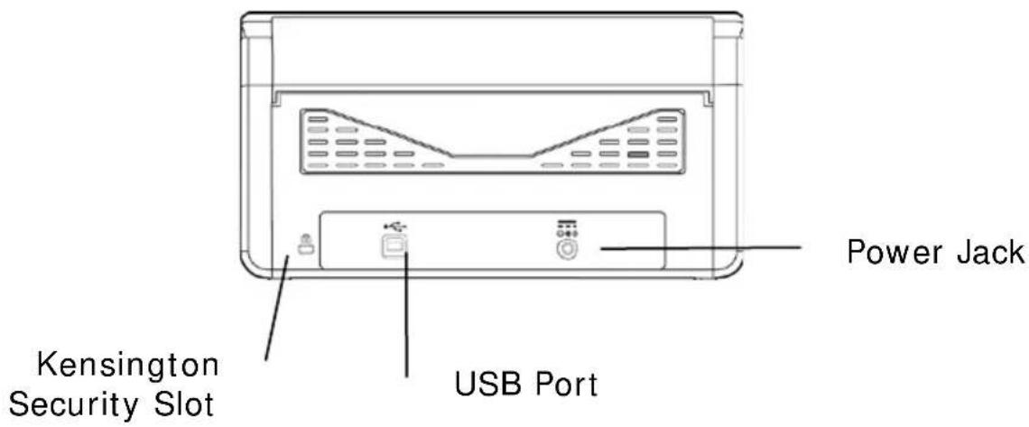
| Part Name Function | |
| USB Port Connect | to your computer. |
| Power Jack Connect | ct the AC adapter to the scanner. |
| Kensington Security Slot | Attach to a lock to secure the scanner. |
2. Scanner Installation
2.1 Precautions
- Keep the scanner out of direct sunlight. Direct exposure to the sun or excessive heat may cause damage to the unit.
■ Do not install the scanner in a humid or dusty place.
■ Be sure to use the proper AC power source.
■ Place the scanner securely on an even, flat surface. Tilted or uneven surfaces may cause mechanical or paper-feeding problems.
■ Retain the scanner box and packing materials for shipping purposes.
2.2 Installing the Scanner Driver and Connecting the Cables
NOTE:
1). To ensure your computer can identify the USB scanner, please install scanner driver first before connecting the scanner to your computer.
2). The scanner driver contains TWAIN, ISIS and WIA driver. After the installation of scanner driver is completed, this scanner allows you to scan via a TWAIN, ISIS, or a WIA interface. Start your TWAIN-compliant image editing software application to select a TWAIN or WIA user interface or your ISIS software to select an ISIS user interface. You may also launch Microsoft's Scanner and Camera Wizard to scan via a WIA user interface.
2.2.1 Connecting to Power
Before connecting, make sure the power switch is off.
Plug the small end of the power adaptor into the power jack of your scanner. Insert the other end to an appropriate power outlet.
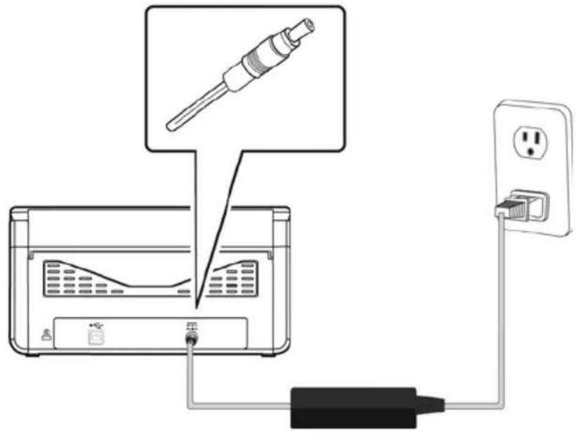
2.2.2 Turning on the Power
Press the Power Switch button on the front panel, the Power LED will flash. When it is finished and ready to scan, the LED indicator will stop flashing and become steadily on. To turn off the scanner, press the Power Switch button for about 3 seconds, the Power LED will be off.
2.2.3 Installing the Scanner Driver
- Place the supplied CD-ROM onto your CD-ROM drive.
- The software installation graphic appears. If not, run "setup.exe".
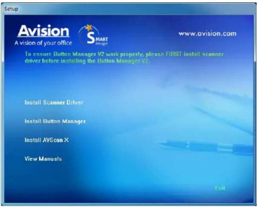
Contents on the installation graphic:
• Install Scanner Driver: To communicate with your scanner, you need to install the scanner driver.
• Install Button Manager V2: To use the buttons on the scanner, you need to install Button Manager V2. To ensure Button Manager V2 works properly, please FIRST install scanner driver before installing Button Manager V2.
• Install AVScan X: To scan and organize your multi-page document(s), you can install the software application to manage them easily and effectively.
• View Manual: Click “View Manual” to view or print the detailed user manual for the scanner and Button Manager V2 respectively.
- Click Install Scanner Driver to install the scanner driver and then click Install Button Manager V2 to install the Button Manager V2 unto your computer.
2.2.4 Connecting to Computer
- Connect the square end of the USB cable to the USB port of your scanner. Connect the rectangle end to the USB port at the rear side of your computer.
Note: The scanner is designed with a USB 3.0 interface to ensure the optimal speed. If your computer comes with a USB 3.0 port, make sure to connect the scanner to your computer to the USB 3.0 port which is distinguished in blue color at the back of your computer. The USB 3.0 port enhances your scanning speed and is also compatible with USB 2.0 and USB 1.1.
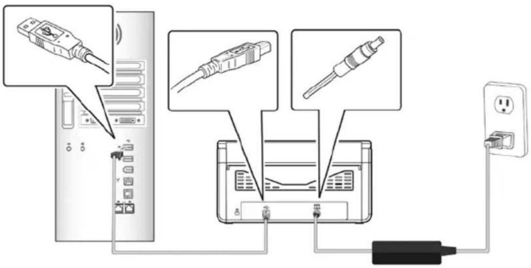
-
The computer should detect a new USB device and prompt a "New Hardware Found" message.
-
By following the on-screen instructions, click the Next button to continue. When the certification screen appears, click Continue Anyway to complete the installation.
-
When the Finish dialog is prompted, click the Finish button.
3. Completing Your First Scan
3.1 Loading Your Paper
3.1.1 Notice on Using the ADF
Before using the ADF, please make sure that your paper meets the following specifications:
- Document (s) can range in size from 50 x 50 mm (2 x 2 in.) to 242 x 356 mm (9.5 x 14 in.)
- Document (s) can range in weight from 27 \~ 413 g/m 2 (7 \~ 110 lb.)
• ID cards up to 1.25 mm (0.05 in.) thick - Document(s) should be square or rectangular and in good condition (not fragile or worn).
- Document(s) should be free of curl, wrinkle, tears, wet ink, or punch holes.
- Document(s) should be free of staples, paper clips, paper sticky notes.
3.1.2 Loading Your Document in the ADF Paper Tray
Fanning Your Document
Note:
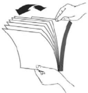
To avoid occasional multi-feeds or paper jams, please fan your documents and align the top edges before feeding them into the scanner.
- Hold both ends of the documents and fan them a few times.
natural_image
Illustration of hands holding a stack of papers with an arrow indicating rotation (no text or symbols)- Rotate the documents by 90 degrees and fan them in the same manner.
- Align the edges of the documents in a step-like pattern (see picture below).
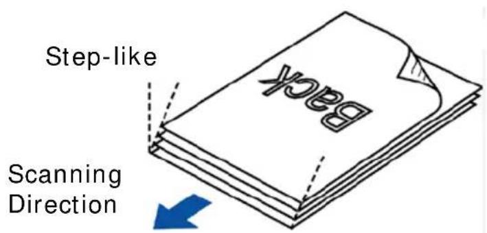
Document Feeding
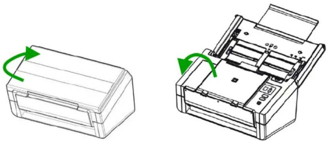
- Unfold the document feeder and its extension.
- Unfold the output tray and raise the paper stopper.
natural_image
Technical line drawing of a printer with green arrows indicating rotation, showing front and side views (no text or symbols)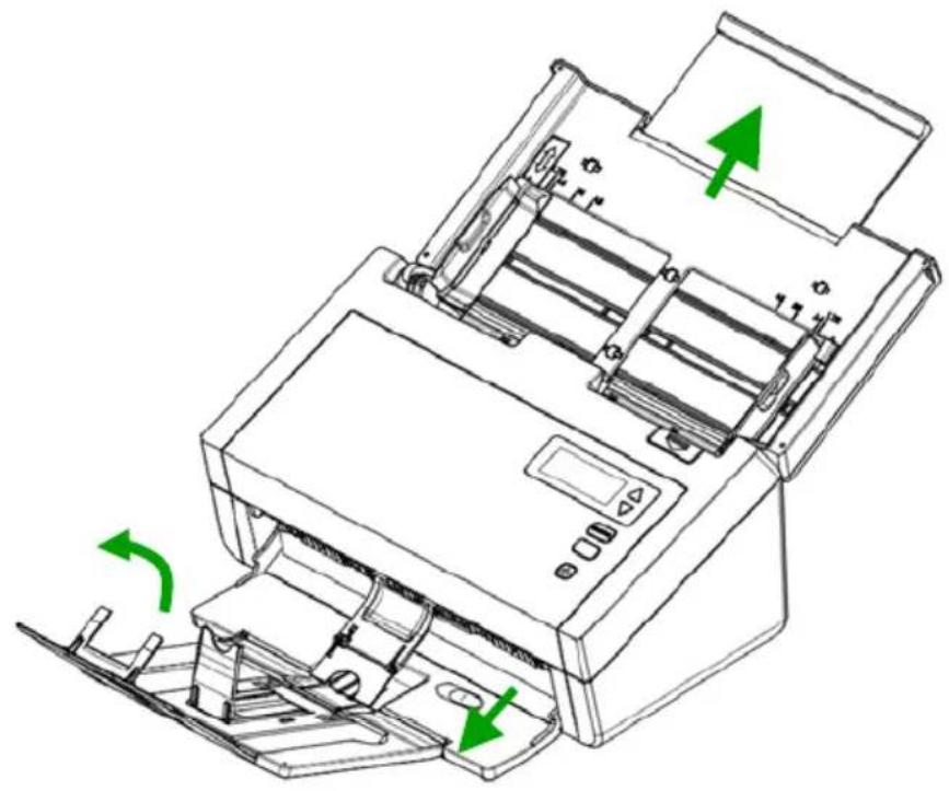
natural_image
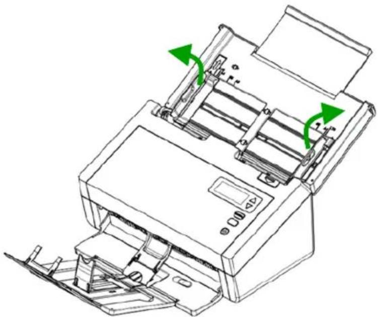
Line drawing of a printer with green arrows indicating motion or operation, no text or symbols present- Raise the paper guide to hold your multi-page document.
natural_image
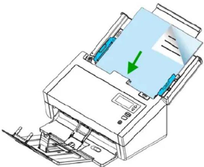
Line drawing of a printer with green arrows indicating directional movement (no text or symbols)- Load the stack of document face down with the top of the pages pointing into the feeder.
natural_image
Illustration of a printer with paper being inserted, showing paper sheet and printer handle (no text or symbols)- Verify that the paper guides are aligned with the edges of the stack.
Note: The [Paper Width] switch:
If your document width is 216 mm (8.5 in.):
If your document width is 216 mm (8.5 in.), slide the [Paper Width] switch DOWN to fix your paper guide to conveniently load the letter-size document.
If your document width is larger than 216 mm (8.5 in.):
If your document width is larger than 216 mm (8.5 in.) such as invoices with punch holes, slide the [Paper Width] switch UP and move the paper guide to the right end to load your documents.
Slide DOWN the [Paper Width] switch to set your paper width to 216 mm (8.5 in.)
![N the [Paper ] switch to set r width to 216 mm (8.5 in.)](/content/2026/06/1312892/images/895c2f01a98b51371cafa34441cbc7096f5b6037a7a28bd5e1870814f7f3f4f0.jpg)
Slide UP the [Paper Width] switch to set your paper width larger than 216 mm (8.5 in.)
![Paper Width] et your paper than 216 mm (8.5 in.)](/content/2026/06/1312892/images/9b3ab63a927328d702a9fb2f7f7a640fdb8f84e397f59571eaf1e1af92e2f137.jpg)
3.1.3 Scanning Thin Paper
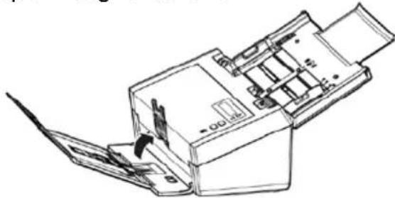
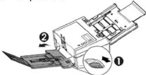
To scan a stack of thin paper, it is recommended to raise the paper weight and then make the output tray in a flat position to keep the paper from rolling or possible paper jams due to the paper stack in the output tray.
For normal document scanning, press down the paperweight and keep the output tray in an angled position to prevent paper from falling apart.
To scan thin paper,
- Lift up the paperweight as shown.
natural_image
Line drawing of a mechanical device with a tool inserted, showing internal components and no text or symbols.- Slide the position adjuster of the output tray to make the output tray in a flat position.
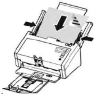
- Load a stack of thin paper into the paper tray. Align the paper guides and make sure the edges of paper slightly touch the paper guides on both side as illustrated.
natural_image
Diagram of a printer with a paper feeding into a stack, showing internal components and arrows indicating process flow (no text or symbols present)3.1.4 Scanning a Stack of Document with Various sizes and Weights
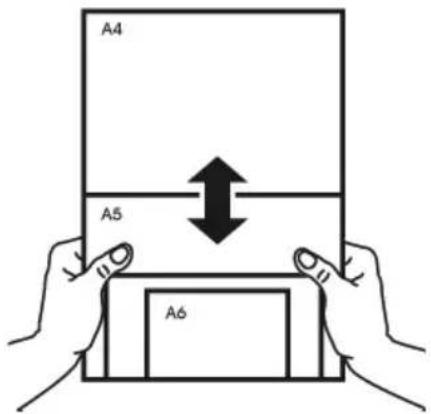
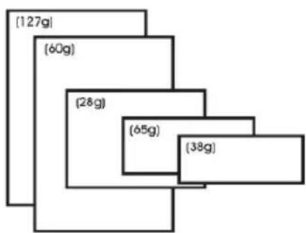
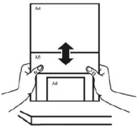
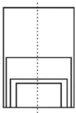
When scanning a batch of documents with different sizes and weights, be sure to follow these guidelines to avoid a skewed image or a paper jam:
- Align the documents TOP EDGE first in the sequence of paper size from large to small.
- If two pages are of the same size yet with different weight, arrange these pages in the sequence of paper weight from heavyweight to lightweight.
bar_stacked
| Category | Weight (g) | |---|---| | [127g] | 0 | | [60g] | 0 | | (28g) | 0 | | (65g) | 0 | | (38g) | 0 |- Align the edges of the documents by tapping the bottom of the stack against the table top.
- Center these pages in the document feeder and make sure that the edges of page of the largest size slightly touch the Paper Guide.
natural_image
Pure geometric diagram of nested rectangles with a vertical dashed line (no text or symbols)3.2 Verifying Your Scanner Installation
To verify if your scanner installation is correct, Avision provides you a useful test program called Avision Capture Tool. With this tool, you can perform simple scans and view the captured images. In addition, it helps you complete your scan at a rated speed.
The following procedure describes how to verify your scanner installation. If the installation is not correct, please review the preceding section to check if the cable connection and scanner driver have been successfully installed.
Before you begin, be sure the scanner is on.
- Select Start>Programs>Avision xxx Scanner>Avision Capture Tool. The Select Scanner Model dialog box will be displayed.
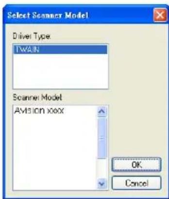
- Select your driver type and scanner model and click OK. The following Avision Capture Tool dialog box will be displayed.
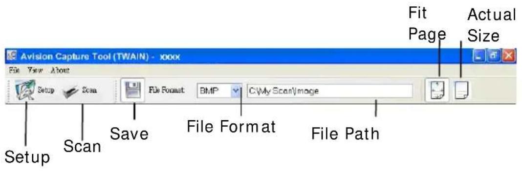
- Choose your desired file format from the File Format drop down list box. (Default is JPEG, other choice includes TIFF, MTIFF, PDF, MPDF, GIF, and BMP.) The supported file formats vary depending on your scanner model.
- Type your desired folder name and file name in the File Path box. (Default is C:\Documents and Settings\User Name\My Documents\My Scan\Image.)
Note: If you do not wish to save the scanned image, deselect the Save button since default is Save Enable. In this case, the thumbnail view will be disabled. And therefore, after viewing all the scanned images, only the last one will remain on the screen.
- Click the Setup button ( ) or choose Setup from the File menu to prompt the Scanner Properties dialog box.
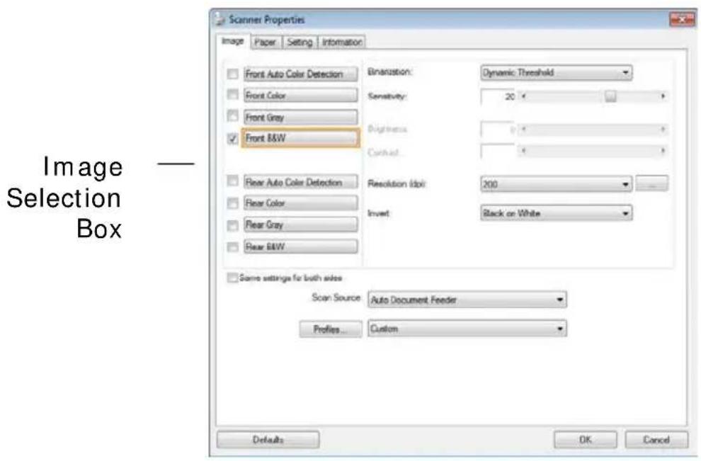
- From the Image Selection Box, choose your desired image type for your scanned image. (Default is Front B&W) If you have a duplex scanner, choose Front and Rear to scan both sides of your document.
- Click OK to quit the Scanner Properties dialog box. (To learn more details about the Scanner Properties dialog box, please see the subsequent chapter, Using the Scanner Properties Dialog Box.)
- Place your document face down on the document glass or face up in the auto document feeder.
- In the Scan Validation dialog box, click the Scan button
or choose Scan from the File menu.
- The document will be scanned and displayed in the Scan Validation screen. After the scanned images have been displayed, your scanner installation verification is completed.
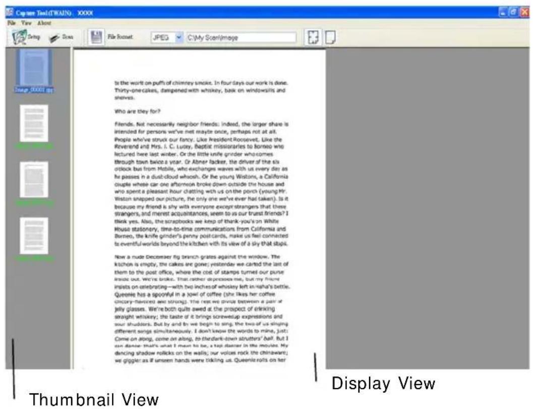
- You can view the scanned image in Fit Page (☐) or Actual Size (100%) button (☐) from the Viewing toolbars at the right side.
- Click the Close box or Quit from the File menu to exit the Scan Validation Tool.
3.3 A Glance of the Scanner Properties Dialog Box
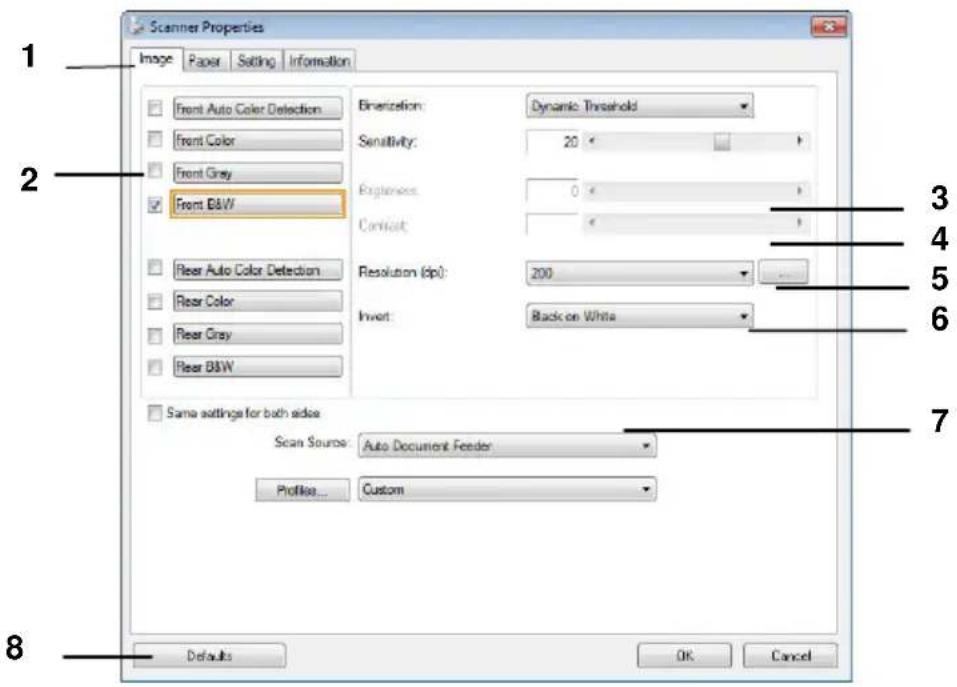
| 1. Tab Options | Choice: Image, Compression, Color Dropout, Paper, Multi-Feed Detection, Preview, Options, Settings, Information. |
| 2. Image Selection Box | Choose your image type and the side of document you wish to scan. Options vary based on type of scanner. |
| 3. Brightness | Adjust the brightness level from -100 to +100. |
| 4. Contrast | Adjust the contrast level from -100 to +100. |
| 5. Resolution | Determine the quality of the scanned image. The industry standard is 200 dpi. |
| 6. Invert | Reverse the color of your scanned image. |
| 7. Scan Source | Choice: Auto Document Feeder, Flatbed, Flatbed (Book), Automatic (varies due to different scanner model) |
| 8. Defaults Reset | all values on the tabs to the factory default settings. |
4. Using the Scanner Properties Dialog Box
The Scanner Properties dialog box allows you to configure the scanner's settings. It consists of several tabbed windows each of which will be described in this chapter.
Note: In this chapter, all options are available based on a duplex (double-side) scanner. If you have purchased a simplex (single-side) scanner, all options are available for single sided only.
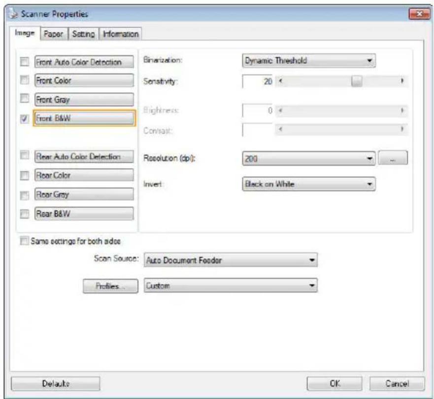
The Scanner Properties dialog box
4.1 Buttons on the Scanner Properties Dialog Box
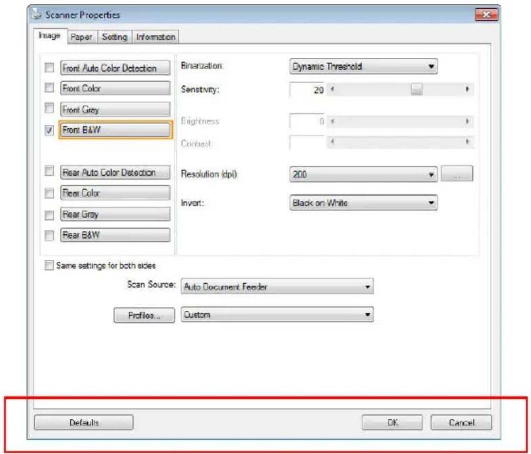
The buttons on the Scanner Properties dialog box
| Buttons | Description |
| Defaults | Click the Defaults button, the factory default settings will be shown on each tab. |
| Cancel | Click the Cancel button to leave the Scanner Properties dialog box. |
The following table shows the default settings :
| Tab name | Default settings |
| Image | Image: Front B&W Binarization: Dynamic Threshold Resolution: 200 dpi Invert: Blank on White Scan Source: Auto Document Feeder Threshold: None Brightness: None Contrast: None |
| Compression None | |
| Color Dropout | None |
| Paper | Cropping: Automatic Deskew: Yes Orientation: Portrait OverScan: 0.00 Note: The availability of this option varies due to scanner model. Unit: Inch |
| Multi-Feed Detection | None |
| Preview None | |
| Options | Rotation Degrees: None Blank Page Removal: None Edge Fill: White, 0 mm Image Control Option: None |
| Setting | Enable Energy Saver: Enable, 15 minutes after last scan action Show Scanning Progress: Yes Show Warning Message: Yes Save Settings after Closing: Yes |
| Imprinter Digital Imprinter | |
4.2 Showing or Hiding Tabs
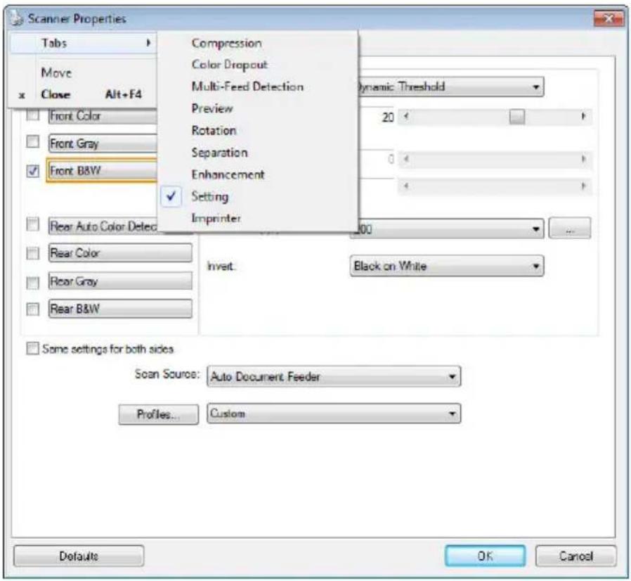
The [Scanner Properties] dialog box is displayed in default with three basic tabs - Image, Paper, and Information. To show more tabs, click the [Scanner Properties] icon to access more scan settings.
To show more tabs,
- Click the [Scanner Properties] icon ( ) on the upper left corner, and choose [Tab] to show available tab names. The available tabs include Compression, Color Drop out, Preview, Rotation, Separation, Multi-Feed, Options, Settings, and Imprinter. (Note: the options vary based on scanner model.)
- Choose the tab you want to display. The selected tab will be shown with a check mark and then displayed in the [Scanner Properties] dialog box.
- To access the settings, click the selected tab on the top of the [Scanner Properties] dialog box. The page of the selected tab will be displayed.
To hide a tab window,
- Click the [Scanner Properties] icon (☐) on the upper left corner, and choose [Tabs] to show available tab names.
- Choose the tab you want to hide. Then, the selected tab will be hid in the [Scanner Properties] dialog box.
Note: The [Image], [Paper], and [Information] tab can not be hided since they preprogrammed to be displayed by default.
4.3 The Image Tab
The Image tab allows you to choose the front side and (or) the rear side of your document, the type of image, and to set several basic scan settings. Note that except for the resolution, you can set individual scan settings for the front side and the rear side. For example, all settings in the Image tab,
Compression tab, Color Dropout tab can be set individually for the front and the rear side. However, the settings in the Paper tab, the Option tab, and the Setting tab have to be set the same for the front and rear side.
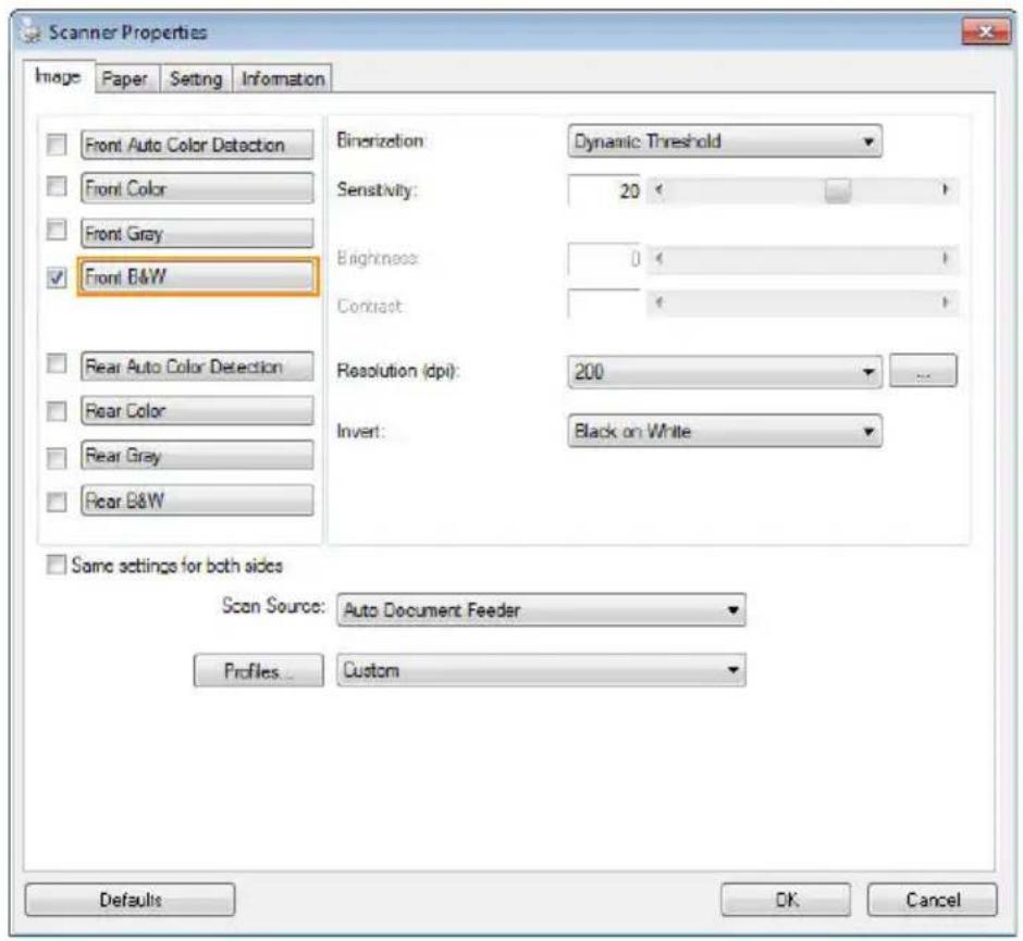
The Image tab dialog box
4.3.1 The Image Selection Box
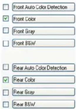
The Image Selection box includes the image type and document side option. If you wish to scan both the front side and the rear side of your color document, you can check both Front Color and Rear Color at the same time. Note the options vary based on type of scanner.
Example 1 : Scanning a two-sided color document, both sides in color
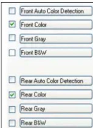
Side/ Image Selection
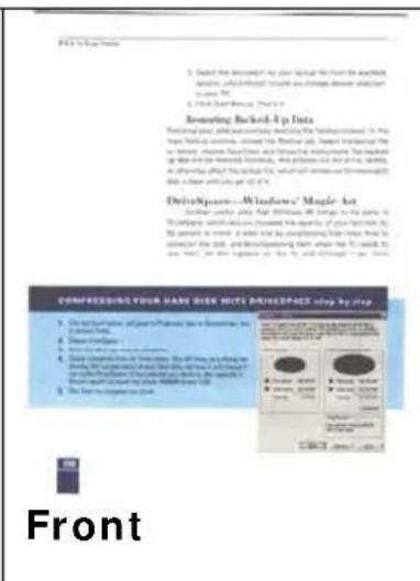
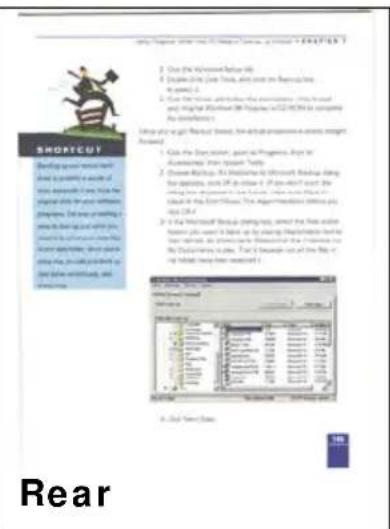
Example 2 : Scanning a two-sided color document, one in B&W, the other in color
| Front Auto Color DetectionFront ColorFront GrayFront B&WRear Auto Color DetectionRear ColorRear GrayRear B&WSide/ Image Selection |  |  |
| Front | Rear |
| Image Type | Description |
| Color Choose | Color if you wish to scan a color image for your original in color. |
| Gray | Choose Gray image if your original contains actual shades of gray. |
| B&W | Choose B&W if your original contains only text, pencil or ink sketch. |
B&W
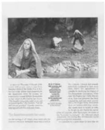
Gray
Front/ Rear Auto Color Detection:
Click to automatically detect and scan the front or the rear page of your color document in color image mode. If your document is in colors, the scanner will automatically scan the document into a color image. If your document is non-color, you can choose the output to be either B&W or Gray from the Non-Color Selection option. This option is useful when you have a mixture of color and non-color document.
Note: If you choose Front Rear Auto Color Detection, you can not specify the image mode of your rear page and vice versa.
Modes of Auto Color Detection:
If [Front/ Rear Auto Color Detection] is selected, its modes will be displayed. Choice includes Normal, Ignore Paper Color. For paper with background color such as invoices, choosing [Ignore Paper Color] will automatically remove the background color and enhance the detection accuracy.
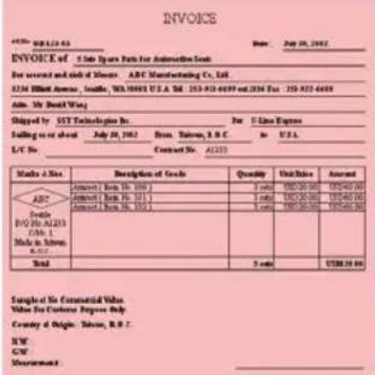 | 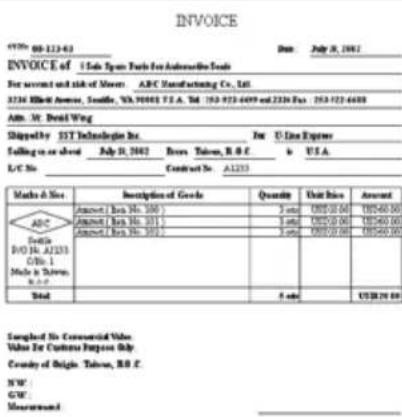 |
| Normal | Ignore single background color |
Sensitivity of Auto Color Detection
If your documents contain primarily B&W text and small amount of light or pale colors and you do not wish them to be recognized as color image to save the file size, you can increase the sensitivity value by moving the bar to the right to let these images to be detected as B&W. The value ranges from 1 to 100. The default is 37.
| Standard | IEEE 802.11 b/g/n standards compliant | |
| Wireless LAN | 1TIR Mode | |
| Frequency Range | 2.400 ~ 2.4835GHz (subject to local regulations) | |
| Number of Selectable Channels | 802.11n: 20MHz/40MHz | |
| 802.11b/g: | USA, Canada (PCC):11 channels(2.412GHz~2.462GHz)Europe (CE): 13 channels (2.412GHz~2.472GHz)Japan (TELEC): 14 channels(2.412GHz~2.4835GHz) | |
| Data Rate | 802.11n: up to 150Mbps802.11b: 1, 2, 5,5, 11Mbps802.11g: 6, 9, 12, 18, 24, 36, 48, 54Mbps | |
| Transmit Power(EIRP) | 11n HT40 MCS7 : +13 dBm11g OPDM: +15 dBm11b CDK: +18 dBm | |
| Security | WEP 64/128, TKIP, WPA, WPA2 mixed,802.1x and 802.11i | |
Original
| Standard | IEEE 802.11 b/g/n standards compliant | |
| Wireless LAN | 1T1R Mode | |
| Frequency Range | 2.400 ~ 2.4835GHz (subject to local regulations) | |
| Number of Selectable Channels | 802.11n: 20MHz/40MHz | |
| 802.11b/g: | USA, Canada (PCC):11 channels(2.412GHz~2.462GHz)Europe (CE): 13 channels (2.412GHz~2.472GHz)Japan (TELEC): 14 channels(2.412GHz~2.4835GHz) | |
| Data Rate | 802.11n: up to 150Mbps802.11b: 1, 2, 5,5, 11Mbps802.11g: 6, 9, 12, 18, 24, 36, 48, 54Mbps | |
| Transmit Power(EIRP) | 11n HT40 MCS7 : +13 dBm11g OFDM: +15 dBm11b CCK: +18 dBm | |
| Security | WEP 64/128, TKIP, WPA, WPA2 mixed,802.1x and 802.11i | |
| Sensitivity: 1(The image is recognized as a color one) | Sensitivity: 100(The image is recognized as a black and white one) | |
Same settings on both sides:
Click to apply same scan settings for both sides of your documents. After checking this option, any settings you have changed will automatically applied to both the front side and the rear side. For example, if you choose your ideal resolution to be 300 dpi, this will be applied both to the front side and rear side of your document.
4.3.2 Other Image Options
Binarization
This is the process of converting a grayscale or color image to a bi-tonal image. There are several different methods of performing this conversion.
Options: Dynamic Threshold, Dynamic Threshold (AD), Fixed Processing, Halftone 1\~5, Error Diffusion.
Dynamic Threshold: Selecting Dynamic Threshold allows the scanner to dynamically evaluate each document to determine the optimal threshold value to produce the highest quality image. This is used to scan mixed document containing faint text, shaded background, or color background with a single setting. If Dynamic Threshold is selected, Threshold, Brightness, and Contrast are not available.
Dynamic Threshold (AD): Selecting Dynamic Threshold (AD) to perform the enhanced mode of the Dynamic Threshold feature. However, using this mode may slow down your scanning speed.
Sensitivity of Dynamic Threshold
Occasionally your scanned image may contain small dots or speckles. To remove these spots, increase the sensitivity value by moving the bar to the right. The value ranges from 1 to 30. The default is 20.
Fixed Processing: Used for black-and-white and other high contrast documents. A single level is set to determine the black-and-white transition. The threshold is programmable over the entire density range. Fixed Processing sets Contrast to 0. If Fixed Processing is selected, Contrast is not available.
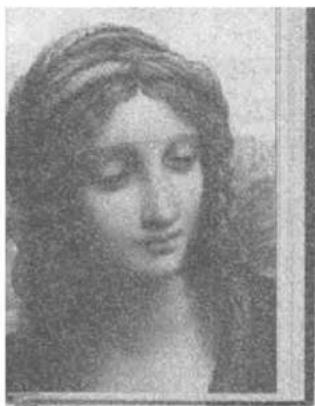
Halftone: In addition to the black and white display, Halftone can present a somehow gray shade of image by using different size of dots. Halftone image looks like the picture we have seen in the newspaper. Options include Halftone 1, Halftone 2, Halftone 3, Halftone 4, Halftone 5.
Error Diffusion: Error Diffusion is a type of Halftone. Error Diffusion gives good image texture and makes text in images more readable than Halftone.
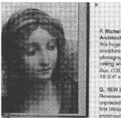
Halftone Image
natural_image
Portrait of a woman with detailed facial features (no visible text or symbols)
Error Diffusion Image
 |  |
| Dynamic Threshold | Dynamic Threshold (AD) |
Threshold Used to convert a grayscale image to a bi-tonal image. The value ranges from 0 to 255. A low threshold value produces a lighter image, and can be used to subdue backgrounds and subtle, unneeded information. A high threshold value produces a darker image, and can be used to help pick up faint images.
Adjust the threshold setting by dragging the Threshold sliding bar to the left or right to achieve the desired threshold setting.
200 dpi, Threshold:50, Brightness: 0
200 dpi, Threshold:100, Brightness: 0
Gray
Document Type: Choice: Normal, Photo, Document
Three options of document type are provided when you choose Gray as the image type for your scanned document. Choice: Normal, Photo, Document.
- Document: Choose Document if your original contains pure text or a mixture of text and graphic since it is an optimal setting for regular business document. When using Document, only Threshold can be adjusted.
• Photo: Choose Photo if your original contains photo to reproduce your photo in vivid grayscale image. When using Photo, no Threshold and Contrast can be adjusted. - Normal: When using Normal, Threshold, Brightness, and Contrast can be adjusted.
Threshold: The value ranges from 0 to 255. The default is 230. A low threshold value produces a lighter image, and can be used to subdue backgrounds and subtle, unneeded information. A high threshold value produces a darker image, and can be used to help pick up faint images. Adjust the threshold setting by dragging the Threshold sliding bar to the left or right to achieve the desired threshold setting.
Normal
Photo
Document
(Threshold: 230)
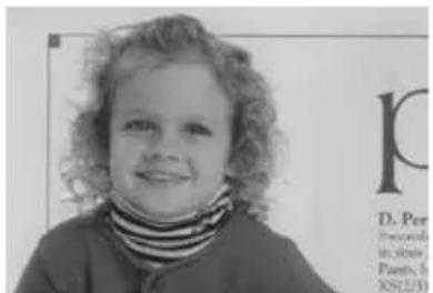
Normal
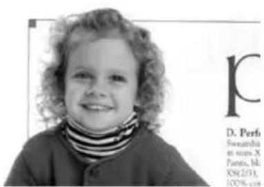
Photo
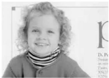
Document
(Threshold: 230)
Brightness
Adjusts the lightness or darkness of an image. The higher the value, the brighter the image. Drag the slider to the right or left to increase or decrease the brightness. The range is from -100 to +100.
Contrast
Adjusts the range between the darkest and the lightest shades in the image. The higher the contrast, the bigger the different grayscale. Drag the slider to the right or left to increase or decrease the contrast. The range is from -100 to +100.
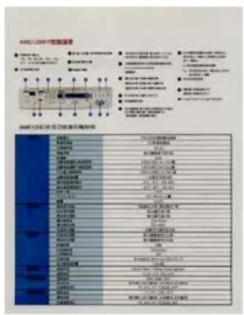
Brightness: 0 (Normal)
Brightness: + 50
Contrast: -50
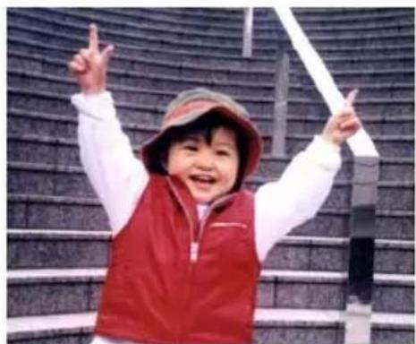
A good control of the resolution results a good detail of an image that scans. The resolution is measured by dots per inch (dpi). Normally, the greater the dpi number, the higher the resolution and the image file size. Be aware that greater resolution takes more time to scan, and more disk space for the scanning image. For your information, an A4 size color image scanned at 300 dpi at True Color mode consumes approximately 25 MB of disk space. A higher resolution (usually means over 600 dpi) is only recommended when you need to scan a small area at True Color mode.
Choose a resolution value from the drop down list. The default value is 200 dpi. Available resolutions are 75, 100, 150, 200, 300, 400 and 600. Or you may choose your desired value by clicking the box in the right side of the drop down list and press the arrow key to select your desired value and then click the Add button to include it in the drop down list. Note: The resolution is up to 300 dpi if an imprinter or a MICR reader is installed or connected to the scanner.

natural_image
Child wearing red vest and hat, raising hands with index finger (no visible text or symbols)Resolution: 75 dpi
natural_image
A smiling child in a red vest and hat, posing with raised hands against a textured wall background (no text or symbols visible)Resolution: 150 dpi
Invert
Reverses the brightness and the colors in the image. The default setting is Black on a White background. Reverse mode is White on a Black background. For color images, each pixel will be changed into its complementary color at the command of Invert.
"I am not worthy to have you enter my
that is God, I beg all my brothers - those we who work manually, clerics and lay brothers ards being humble in all things; not to glorify r to become interiorly proud because of good w sometimes says or does in them or through t ord: "Do not rejoice... in the fact that the de : 10:20) Let us be firmly convinced of the fact
Black on White
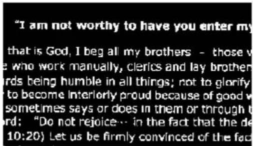
White on Black
Scan Source
Choice:
- Auto Document Feeder: Used to scan multiple pages.
- Flatbed: Used to scan a single page. For example, pages from newspaper clipping, paper with wrinkles or curls.
- Flatbed (book): Used to scan several inside pages from book.
- Automatic: Allow the scanner automatically set its scan source. If Automatic is selected and there is document in both the auto document feeder (ADF) and the flatbed, then the scan source will be automatically set to ADF. If Automatic is selected and there is document only in flatbed, then the scan source will be set to flatbed.
- Merge Two Sides into One Image:
If you have a sheet-fed duplex scanner with front input tray, you can scan an A3 size document with an innovative method. Thus, fold your A3 size document into A4, and then load the paper in the front tray. Choose Merge Two Sides from the Scan Source option and then the scanner is able to scan both sides of your document and merge two A4 images into one A3 image.
When you select Merge Two Sides into One Image, the Cropping or Multi-feed function will be disabled.
Note: This feature must be used with a carrier sheet. Regarding how to load a document with a Carrier Sheet, refer to Section 4.6.2, Other Paper Selection.
Note the options vary based on type of scanner.
Note: If you have purchased a duplex sheet-fed scanner, choose [Merge Two Sides] on the [Scan Source], then the scanner is able to scan both sides of your document and merge them into a single image.
If “Merge Two Sides into One Image” is selected, its choice will be available including “Merge Horizontally”, “Merge Vertically”, “Merge Vertically (Back Side Flip)”. If the reverse side of your document is upside down, choose “Merge Vertically (Back Side Flip)” and the back side will be automatically rotated 180 degrees and merged.
| Front Side |
| Rear Side |
Merge Vertically
| Front Side | Rear Side |
Merge Horizontally
Note the options vary based on type of scanner.
Color Matching
The purpose of Color Matching is getting the accurate color. This option uses the default parameters (ICC profile) to adjust the colors of the image.
Choice: None, Document, Photo
- None: Choose "None" to disable this option.
- Document: Choose "Document" if your original contains pure text or a mixture of text and graphic since it is an optimal setting for regular business document.
- Photo: Choose "Photo" if your original contains photo to reproduce your photo in vivid color image.

natural_image
Still life arrangement of assorted fruits and vegetables including a basket, glasses, wine bottle, and sliced meat (no text or symbols visible)Normal

natural_image
Assorted fresh vegetables and fruits arranged on a table, including a basket of bread, glasses, and wine bottle (no visible text or labels)After Color Matching
4.3.3 Scanning color images
The following options are available for scanning color images.
- Brightness
- Contrast
- Resolution
- Invert
4.3.4 Scanning grayscale images
The following options are available for scanning gray images.
- Brightness
- Contrast
- Resolution
- Invert
4.3.5 Scanning B&W images
The following options are available for scanning B&W images.
• Binarization (Dynamic Threshold)
- Resolution
- Invert
Or
• Binarization (Fix Processing)
- Threshold
- Brightness
- Resolution
- Invert
4.3.6 Editing Profiles
The Scanner Properties dialog box allows you to change and save your frequently used scan settings into a profile. You can edit these profiles by renaming or deleting them.
To add a new profile,
- Customize your settings. (For example, change your resolution, image type, cropping method, scan size, or other scan settings.)
- Click the Image tab and then choose "Profiles" to prompt the "Edit Your Profile" dialog box.
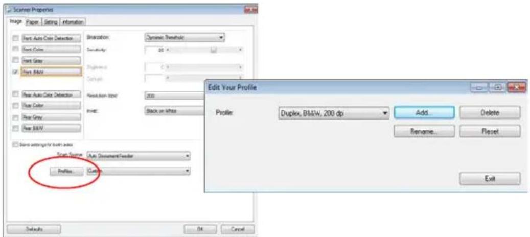
- Click "Add" to enter the name of the profile and then choose "Save".
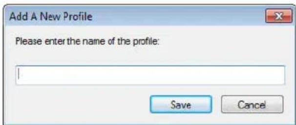
- The new profile will be saved and shown in the "Profiles" dropdown list box.
To load a profile,
- From the Image tab dialog box, choose your favorable profile from the "Profiles" dropdown list box.
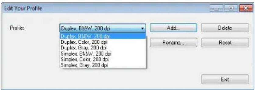
- Your favorable profile will be immediately loaded and displayed on Scanner Properties dialog box.
To delete a profile,
- From the Image tab dialog box, click "Profiles" to prompt the Edit Your Profile dialog box.
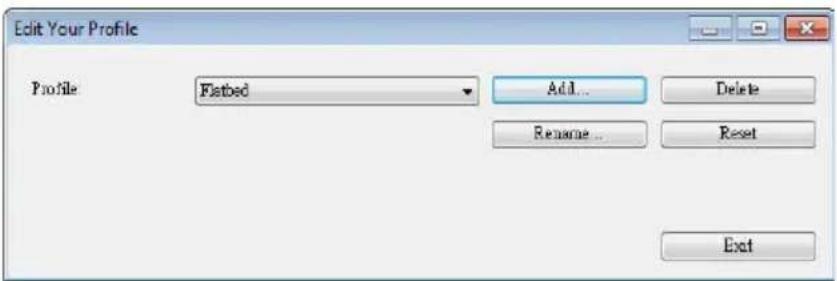
- Choose the profile you want to delete from the dropdown list box.
- Click "Delete". A Confirm message "Are you sure you want to delete this profile?" is prompted.
- Choose "Yes" to delete or "Cancel" to quit.
To rename a profile,
- From the Image tab dialog box, click "Profiles" to prompt the Edit Your Profile dialog box.
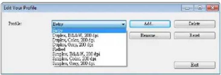
- Choose the profile you want to rename from the dropdown list box and then click the Rename button.
- Enter new name for the profile.
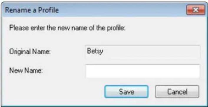
- Choose "Save" to save the new profile or "Cancel" to quit.
Note:
- The preset default profiles include Flatbed, Simplex-B&W, 200 dpi, Simplex-Gray, 200 dpi, Simplex-Color, 200 dpi, Duplex-B&W, 200 dpi, Duplex-Gray, 200 dpi, Duplex-Color, 200 dpi. If you have a simplex or a sheetfed scanner, the duplex or the flatbed option will not be available.
- If any setting for a current profile has been changed, a [*] sign will be marked before the name of current profile, for example, [* Duplex, Color, 200 dpi]. If desire, click the [OK] or [Scan] button and a dialog box will be prompted to let you save the new profile.
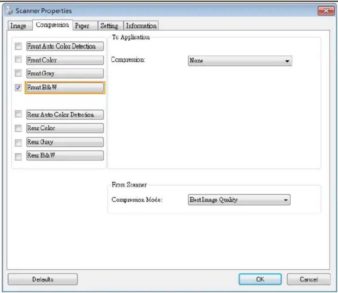
4.4 The Compression Tab
The Compression tab allows you to compress your scanned image and choose the level of compression. Bi-tonal images are normally compressed using CCITT standard called Group 4 (G4). Color and grayscale images are often compressed using JPEG technology. Move the JPEG Quality slider to the right or left to increase or decrease the level of compression. Note the greater the compression level, the lower image quality. Default is 50%.
Note that the compression depends on your image editing application. If your image editing application does not support the type of compression format, then either a warning message will appear or the image quality of the compressed file will not be acceptable.
JPEG (Joint Photographic Editor Group). This group developed and lent their name to a file compression standard for color and grayscale images that is widely used by scanners, and software applications. On Microsoft Windows-based systems, a file with the extension .jpg has normally been compressed using this standard.
For scanning color or gray images, the following compressions are available:
- None
- JPEG
For scanning B&W images, the following compressions are available:
- None
• G4
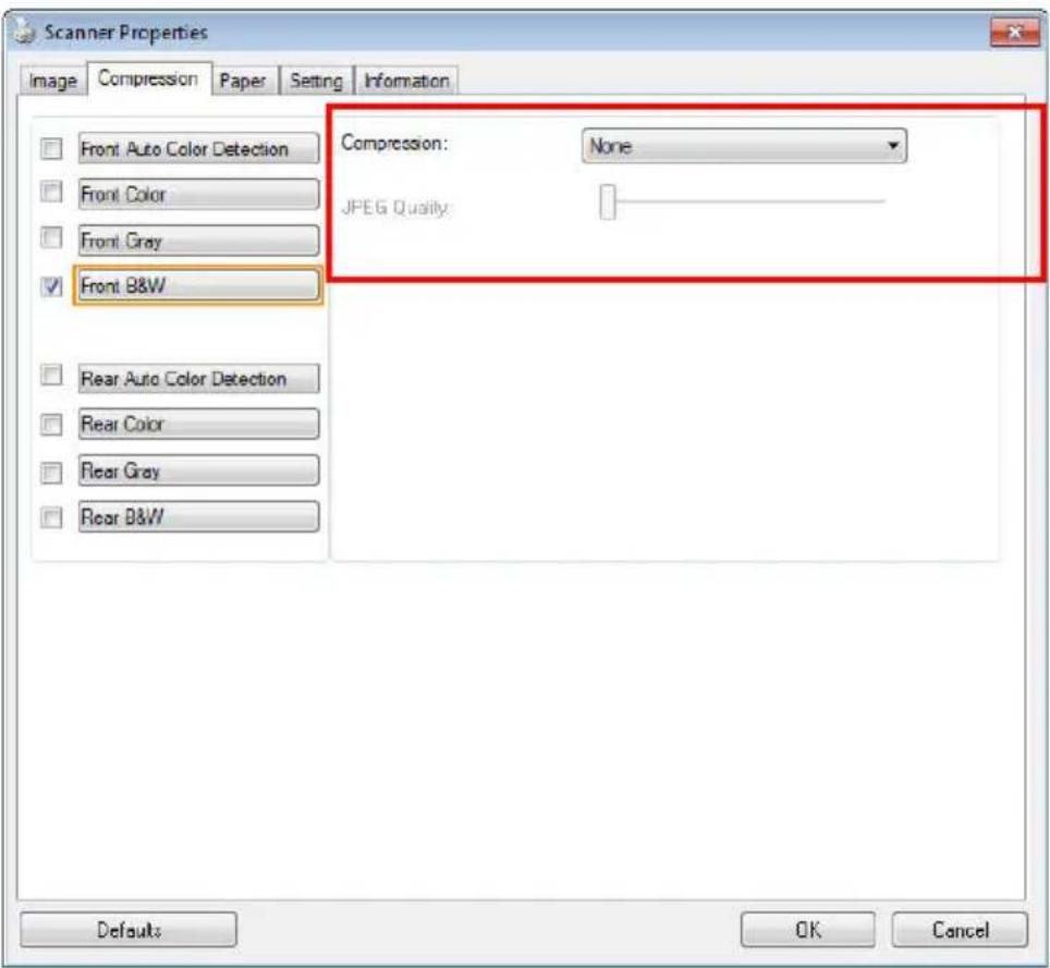
The Compression tab dialog box
Compression:
To complete your scan at a rated speed, the scanned image is compressed by default during transmission. However, if you wish to obtain the highest image quality, you can choose to uncompress the image data before it is output.

flowchart
graph LR
    A["Scanner"] -->|Scanned Image| B["Scanner Driver"]
    B -->|Scanned Image| C["Image Editing Application"]
To Application:
Choose if you wish to compress the image data and transfer it from the TWAIN driver to the application. Note Bi-tonal images are normally compressed using CCITT standard called Group 4 (G4). Color and grayscale images are often compressed using JPEG technology. Move the [Image Quality] slider to the right or left to increase or decrease your image quality. Note the greater the image quality, the lower the compression level. Default is 50%.
Note that the compression depends on your image editing application. If your image editing application does not support the type of compression format, then the image of the compressed file will look abnormal.
From Scanner: (Note: The availability of this feature varies due to scanner model.)
Choose if you wish to compress the scanned image and transfer it from the scanner to the TWAIN driver.
Choice: Uncompressed, * Best Image Quality (Low Compression Level), Better Image Quality (Normal Compression Level), Normal Image Quality (High Compression Level). (*: Factory Default)
4.5 The Color Dropout Tab
4.5.1 Color Dropout Selection
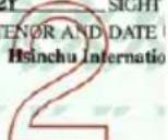
The [Color Dropout] tab allows you to select either green, red, blue, or a color of your choice to remove the details of the selected color from a scanned image. This feature is used to sharpen your text when using OCR (Optical Character Recognition) software. Note this feature applies only to the gray or black and white image.
Choice: None, Auto, Remove Red, Remove Green, Remove Blue, Custom
- None: Does not remove any color.
- Auto: Automatically outputs the image with the details of the primary color removed.
- Remove Red/ Remove Green/ Remove Blue: Outputs the image with the details of the specified color removed.
- Custom: Specify the color you wish to remove by entering its RGB (Red, Green, and Blue) value respectively.
Advanced Options:
- Quality Mode: Range: 0\~20. Default: 10
When [Quality Mode] is selected, you can determine the color to be dropped out using the [Filter Threshold] slider. A lower value will drop more of the selected color out, while a higher value will leave more of the selected color in.
- Normal Mode: Use an optimized setting to determine the color.
  Original Original | 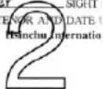 Auto/Remove Green (normal mode) Auto/Remove Green (normal mode) |
  Remove Red (normal mode) Remove Red (normal mode) | 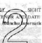 Remove Green (quality mode: Threshold: 18) Remove Green (quality mode: Threshold: 18) |
Preview the color dropout result:
To preview the color dropout result, please follow these steps:
- Click the [Scanner Properties] icon (图标) on the upper left corner, and choose [Tab] to show available tab names.
- Choose [Preview] to show the Preview tab.
- Click the [Preview] tab to show the Preview page.
- Load your document to the scanner and click the [Preview] button to get a preview image.
- On the [Image] tab, click [Gray] or [Black and White] image mode and then choose [Custom] on the [Color Dropout] tab. A [Preview window] button will be displayed.
-
Click the [Preview window] button to prompt the [Preview] window with the previewed image.
-
Move your cursor over the preview image. Your mouse cursor now becomes an Eyedropper.
- Click to select a color which you wish to remove.
- Click and hold your mouse button to view the result after removing the specified color. If the result is satisfactory, click [OK] to close the Preview window.
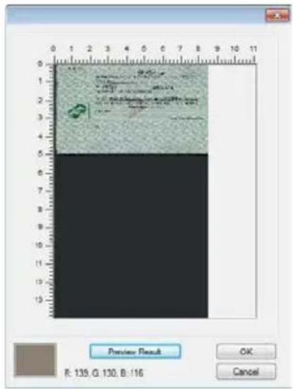
The Preview Window
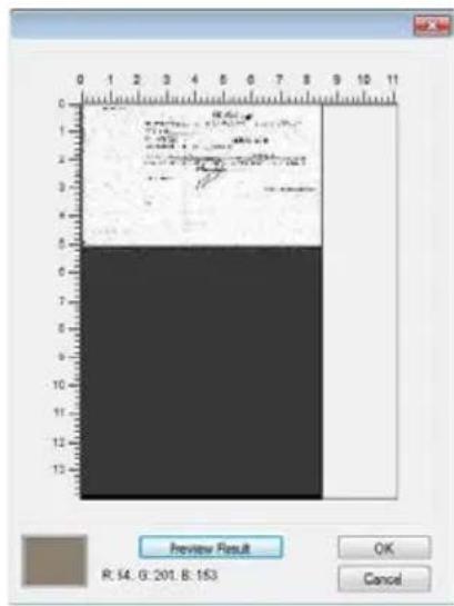
The Color dropout result
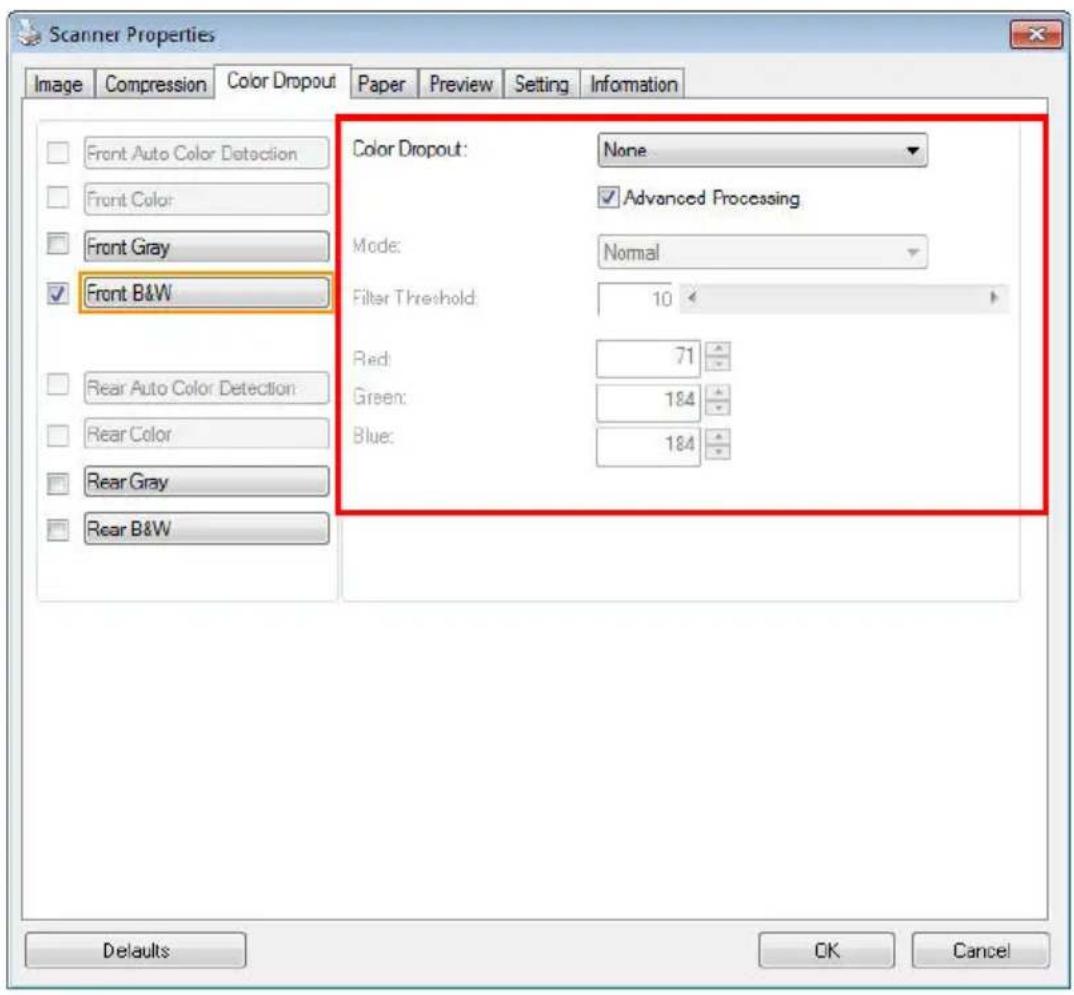
The Color Dropout dialog box
To select a color on the Color palette,
- Click the Color Dropout tab from the Scanner Properties dialog box.
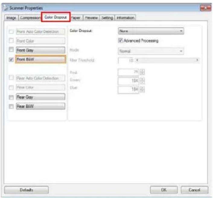
- Choose Gray or B&W from the Image Selection box and click "Custom" from the Color Dropout drop-down menu. The Color palette appears.
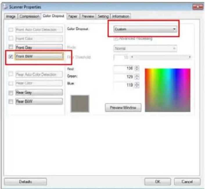
- Move your cursor over the palette. The cursor becomes a cross sign.
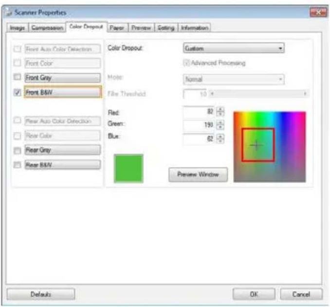
- Click to choose a color. The RGB values are changed simultaneously.
4.6 The Paper Tab
The Paper tab allows you to define values relating to image output (i.e., Auto Crop or not, Scan Area, OverScan, Multi-Feed Detection).
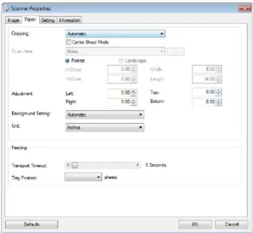
The Paper tab dialog box
4.6.1 Cropping
Cropping allows you to capture a portion of the document being scanned. Choice: Automatic, Automatic (36"), Fixed to Transport, EOP (End of Page) Detection, Automatic Multiple, Relative to Documents.
| Options Description | |
| Automatic | Automatic adjusts the cropping window according to different document sizes and automatically straighten a skewed document. Use this option for batches of mixed-sized documents. |
| Automatic (36") | Automatically adjusts the cropping window according to different document sizes smaller than 36" and automatically straighten a skewed image. Use this option for batches of mixed-sized document. Note: The availability of this feature varies due to scanner model. |
| Fixed to Transport | This feature allows you to define the area or zone to be imaged. Use for batches of same-sized documents. If you select this option, you can use the arrow keys to define the x and y offset values, width and length to redefine your scanned area. The Display window will show image placement as you change the values. |
| EOP (End of Page) Detection | This feature allows you to define the area or zone to be imaged. Use for batches of same-width but different length documents. If you select this option, you can use the arrow keys to define the x and y offset values, width and length to redefine your scanned area. The Display window will show image placement as you change the values. |
| Automatic Multiple | This option allows you to place various sized documents such as photos, ID Cards, or business cards on the flatbed (if available) and lets you create multiple individually cropped images in one scan. Note: To correctly create multiple images, please make sure there is at least 12mm (0.5") of space between each document. |
| Relative to Document | This option allows you to crop different areas on your documents and deliver these images in B&W, Gray, or Color separately. For example, there are applications which require you to store the entire document in B&W and a part of the document in color to save storage space. This is useful for documents where a photograph or signature appears in a consistent area on the document such as resumes, and so on. |
The following options are only available when Fixed to Transport is selected.
• X-Offset — the distance from the left end of the scanner to the left edge of the scanning area.
• Y-Offset — the position from the top end of the document to the top end of the scanning area.
• Width — the width of the scanning area.
• Length — the length of the scanning area.
• Center: automatically calculates the x-offset for center-fed feeding based upon document size selected.
- — relocate the scan area by click the arrow key on the cross sign while retain the scan size. View the result from the Display window.
The Adjustment option is available when Automatic is selected.
- Adjustment —adds a positive/negative margin value Top/Bottom or toward left/right of the image. □ Adjustment is used when the automatic document feeder is used. Adjustment reduces the possibility of corner clipping on skewed images. To set Adjustment values, use the UP/Down buttons to select where you want to apply Adjustment values: Top/Bottom or Left/Right, and then select the amount of inches/mm/pixels applied. Select a value within the range of 0.00 to 1.00 / -1.00.
Relative to Document: (used for batches of same-sized documents)
This option allows you to crop different areas on your documents and deliver these images in B&W, Gray, or Color separately. For example, there are applications which require you to store the entire document in B&W and a part of the document in color to save storage space. This is useful for documents where a photograph or signature appears in a consistent area on the document such as resumes, and so on.
The following procedure describes how to reproduce the entire document in B&W and a portion of document (picture) in color.
- On the Paper tab, choose "Relative to Document" or "Fixed to Transport" from the Cropping option.
- Choose your scan size from the Scan Area option. The selected scan size will be displayed in a red rectangular box. This is also the scan size of your entire document. (For example, ISO B5. If you have not chosen a scan area and leave the selection as None, then the default area will be the scanner's maximum.)
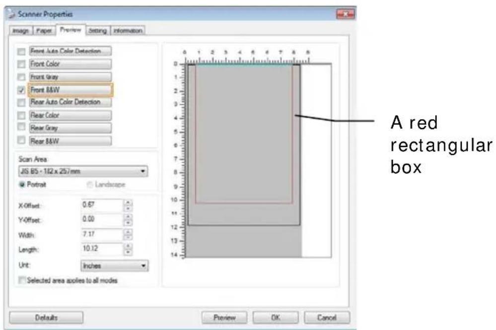
- Click the Preview tab to display the Preview window. A black rectangular box appears to indicate the max. scan size your have just selected.
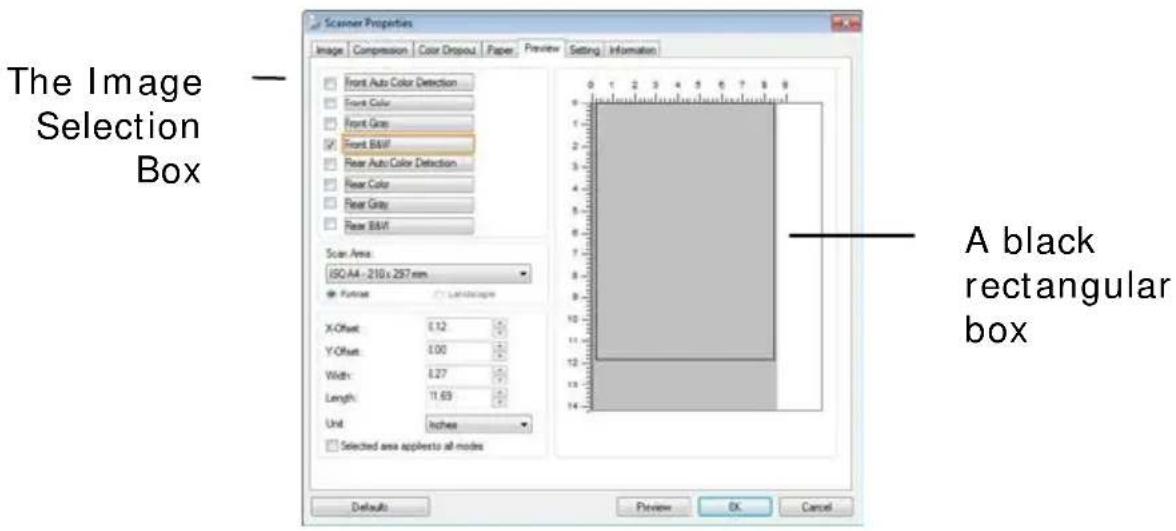
- Click the Preview button to view the entire image in low resolution to correctly crop your relative scan area.
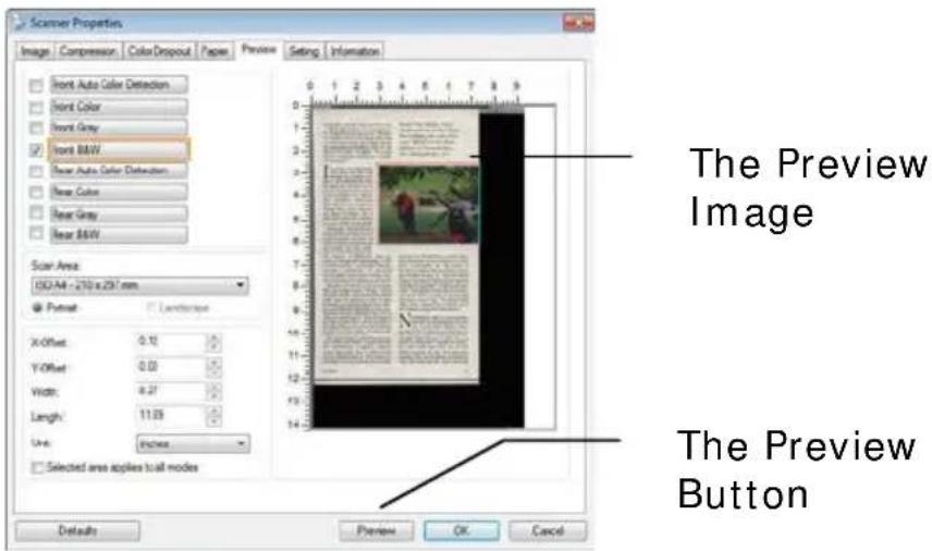
- Select image type from the Image Selection box. The selected image will appear in highlighted color. (For example, Front Color)
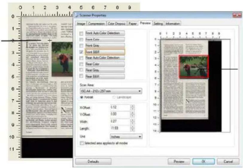
- Place your cursor on the Preview window and click your left mouse button. A cross sign will appear as illustrated. Create your relative scan size diagonally by dragging the left mouse button to your preferable size. The selected area will appear in a red box as illustrated.
A Cross Sign
The Relative Area
- Check the B&W image from the Image Selection box to scan the entire document.
- Click the Scan button to start scanning the document in two image types and sizes. (See the result in below.)
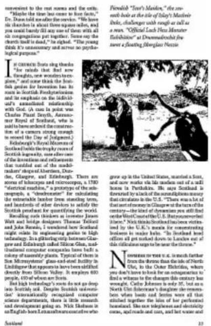
The entire document in B&W

natural_image
Two people outdoors near a pond, one crouching and the other holding an object, with trees and greenery in the background (no visible text or symbols)The relative area in color
4.6.2 Other Paper Selection
Carrier Sheet Mode:
Check this option to automatically crop the scan window according to your document size when scanning non-standard document (fragile, irregular-size document) with a carrier sheet (optional). Note: The availability of this option varies due to scanner model.
Loading Documents Using a Carrier Sheet
A Carrier Sheet is a plastic sheet specifically used for loading non-standard document onto the scanner. It allows you to scan document that can not be scanned in the regular way. Also, documents larger than A4 size, such as A3 and B4, can be scanned by folding in half, inserting into the Carrier Sheet, and scanning in duplex mode. You can also scan documents that can be damaged quite easily such as photographs, or irregular size documents that are difficult to load directly such as clippings.
To scan document using a Carrier Sheet,
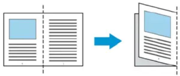
For documents larger than A4/ Letter size, such as A3
a. Fold the sheet to be scanned in half.
b. Fold the sheet tightly and smooth out crease. Otherwise, the sheet may be skewed during scanning.
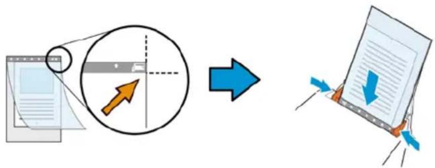
1. Open the Carrier Sheet and place the document inside.
Align the top of the document to the top of the Carrier Sheet (the printed area).
For documents larger than A4/ letter size, such as A3
Align the top of the document to the top of the Carrier Sheet (the printed section) and the folded portion to the right edge of the Carrier Sheet so that the document fits into the Carrier Sheet at the upper corner.
flowchart
graph LR
    A["文件提交"] --> B["文档审核"]
    B --> C["文档分页"]
    C --> D["分页操作"]
    D --> E["分页归档"]
    E --> F["分页归档"]
    style A fill:#f9f,stroke:#333
    style F fill:#bbf,stroke:#333
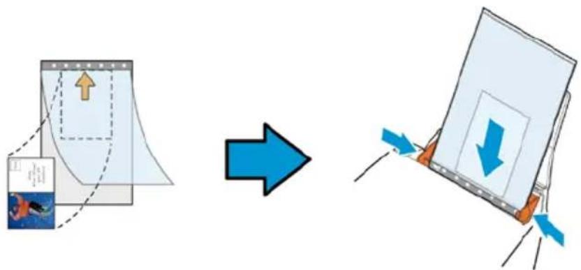
For non-standard document
Center your document in the Carrier Sheet.
-
Load the Carrier Sheet with the gray section (printed section) facing downwards.
-
Adjust the paper guides to the width of the Carrier Sheet. Adjust the paper guides so that there is no space between the guides and the Carrier sheet. Space between the guides and Carrier Sheet may cause the Carrier Sheet to become unaligned during scanning, and skew the scanned image.
-
Start the scan.
Notice:
- [Carrier Sheet] is available for the models that support the Carrier Sheet.
- Some functions are disabled when [Carrier Sheet] is checked.
- This option may not work properly on some applications.
Scan Area
Choose your desired paper size with the drop-down list box. Or you may select a custom paper size by clicking the Scan Area box and then click Add to include in the choice.
Choices are listed below :
| None |
| US Letter- 8.5” x 11” |
| US Legal - 8.5” x 14” |
| ISO A4 - 21 x 29.7 cm |
| ISO A5 - 14.8 x 21 cm |
| ISO A6 - 10.5 x 14.8cm |
| ISO A7 - 7.4 x 10/ 5 cm |
| ISO B5 - 17.6 x 25 cm |
| ISO B6 - 12.5 x 17.6 cm |
| ISO B7 - 8.8 x 12.5 cm |
| JIS B5 - 18.2 x 25.7 cm |
| JIS B6 - 12.8 x 18.2 cm |
| JIS B7 - 9.1 x 12.8 cm |
| Scanner Maximum |
| Long Page (<118”) |
Long Page (<118"):
When you need to scan documents whose length exceeds scanner maximum, please choose Long Page. Note if Long Page is selected, the Multi-Feed Detection will not be available. (Note: This option and the maximum allowable document length vary due to type of scanner.)
When Long Page (<118") is selected, be sure to specify your document size in the Length and Width field.
Notice when scanning long page document:
- Pull out the extension in the ADF Paper Tray.
- Secure enough space around the Output Tray to prevent the ejected paper from falling off the Output Tray.
- To ensure the performance, in color mode, set the resolution to be 300 dpi or lower; in Black and White mode, set the resolution to be 600 dpi or lower.
- Depending on your system environments, application, or your specified paper size, there may be insufficient memory to perform scanning.
OverScan
Overscan allows you to add a specific margin at top and bottom or right and left (Options vary based on the type of scanner) of the edge of the image. This is used to reduce possible corner clipping on the skewed images and often applied to a batch of skewed document to be scanned in the auto document feeder. Select a value between 0 and +5 mm. Note the overscan result will not be shown in the Display window and that the availability of the function varies based on type of scanner.
Pre-Feed
Choice: Enable, Disable. If enable is selected, you can set the amount of time the scanner starts pre-feeding your paper after your documents has been loaded into the feeder. The default is disable. Note: The availability of this option varies due to scanner model.
Transport Timeout
Set the amount of time the scanner will wait and then start auto scan after the first scan job is completed. If you have many separate documents need to be scanned at the same scan settings, this feature is especially useful. The default is 0. The value ranges from 0 to 30 seconds.
Note:
1 Within the specified timeout period, if you load your document to the feeder, the scanner starts scanning automatically.
2 If your scanner has a flatbed option and you place your paper on the flatbed, after the timeout period, you need to click the Scan button on the TWAIN user interface to start scanning.
Background Setting
This option allows you to set your scan background. Choice: White Background, Black Background.
Note: For a sheet-fed scanner with an auto document feeder, this option is currently available only in the “Auto crop” mode. For a scanner with a flatbed platen, this option is available either in the “Auto crop” or the “Fixed to Transport” mode.
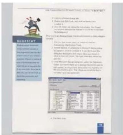
White Background
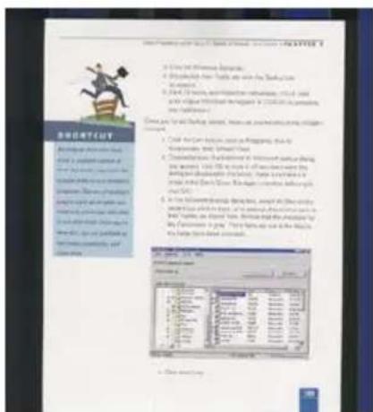
Black Background
4.7 The Multi-Feed Detection Tab
Multi-Feed Detection
Multi-Feed Detection allows you to detect overlapped document that go through the auto document feeder. Multi-Feed usually occurs due to stapled documents, adhesives on documents, or electro-statically charged document. Note: The availability of the function varies based on type of scanner.
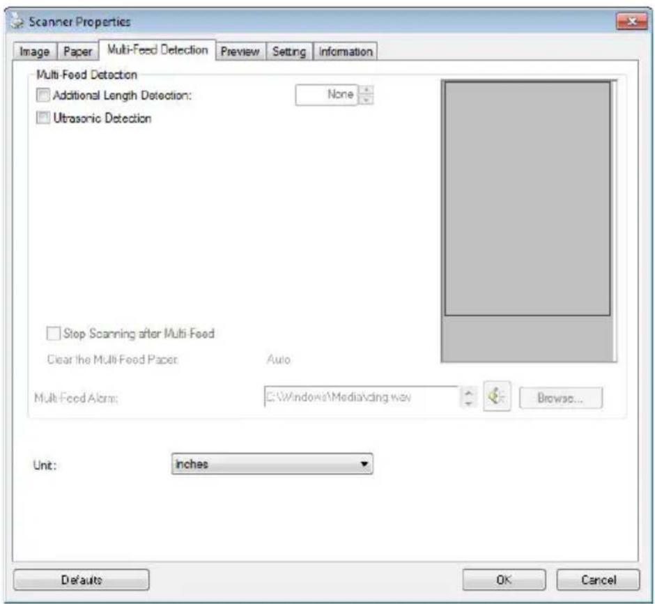
Additional Length Detection
Additional Length Detection allows you to define the length of document being multi-fed. This value indicates the additional length exceeding your scan area. The Display window will show the size of the document as you change the value. A value of 0 indicates no additional length detection. The Additional Length Detection is best used when scanning same-size documents in the auto document feeder.
Ultrasonic Detection
Ultrasonic Detection allows you to set overlapped document by detecting paper thickness between documents. Note: The availability of the function varies based on type of scanner.
There are two options available if Multi-Feed is detected.
- Stop Scanning after Multi-Feed
If this is selected, the scanner will stop the feeder and prompt a multi-feed warning message. In addition, the multi-feed paper will be ejected from the scanner automatically.
Note: The availability of the [Auto Clear Multi-Feed Paper] feature varies based on scanner type. If your scanner does not support this feature, remove the multi-feed paper manually.
If this is not selected, the scanner will continue scanning the entire document though multi-feed is detected. After the entire document has been scanned, a multi-feed dialog box will be prompted to indicate the page number which has been detected multi-feed and need to be rescanned.
- Multi-Feed Alarm
If a wave file is added, the scanner will make a sound alarm if multi-feed is detected yet no Warning dialog box will be displayed.
How to add the sound alarm :
- Click the Browse button on the right side of the speaker icon. The Open dialog box appears.
- Choose your wave file.
- Click the Open button. The wave file is added.
Units
Defines the primary measurement system. Inches, Millimeters, and Pixels are available.
4.8 The Preview Tab
The Preview tab allows you to preview (a low-resolution scan) your image before final scan. This preview image lets you allocate your scan area. You can choose your scan area by the "Scan Area" drop down list box or placing your cursor on the Display window and dragging it diagonally on the Display window. Then, a red rectangle box will appear to indicate the selected area.
Note: If you choose "Automatic Cropping" on the "Paper Tab", then to select a scan area on the Preview tab is not allowed.
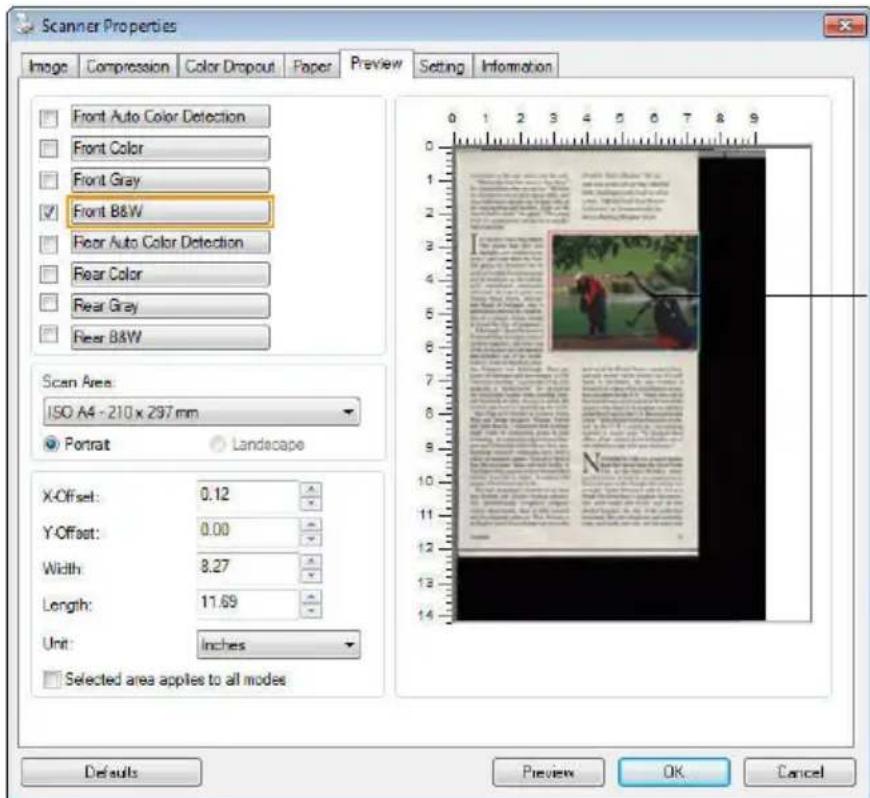
The Display Window
The Preview Tab
4.9 The Enhancement Tab
The Enhancement tab allows you to set following additional image processing settings.
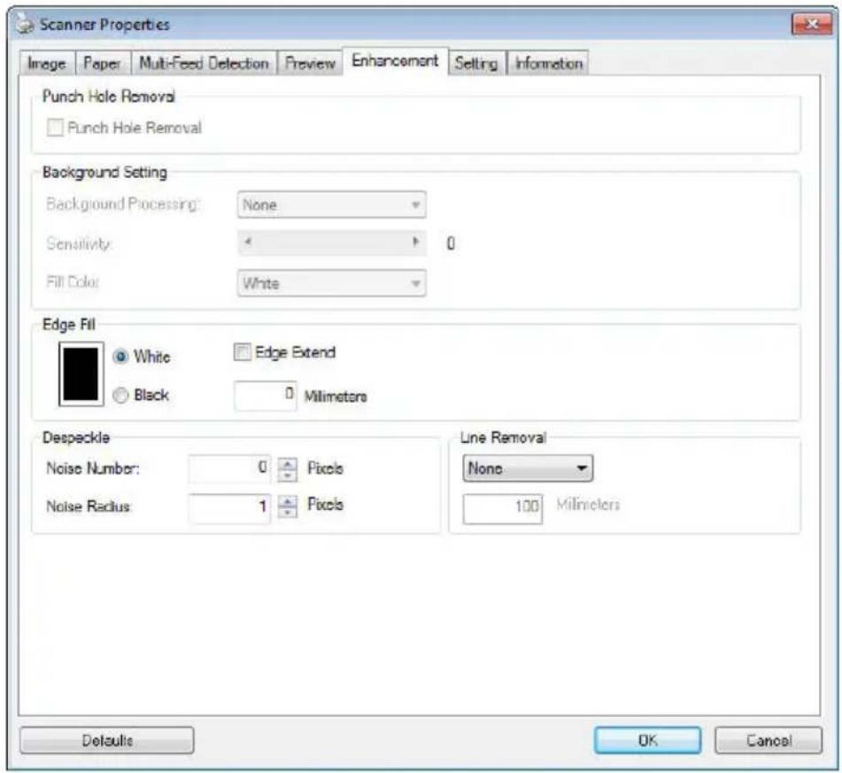
The Option tab dialog box
Punch Hole Removal
You can remove punch holes from the output scanned image when scanning punched document. Note the availability of this feature varies depending on your scanner model.
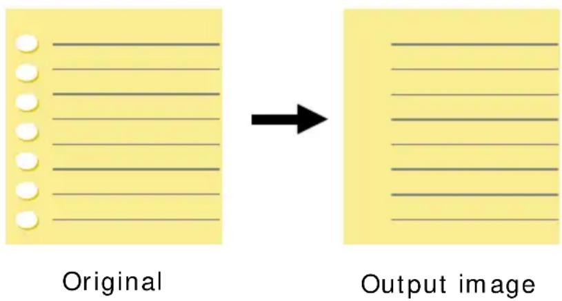
Punch holes can not be removed when:
• Resolution is set lower than 150dpi
- The hole is near the edge of the document
- The holes are not aligned along the edge of the document
- Punch Hole Removal is available only when “Auto Crop” is enabled. If either “Fixed to Transport”, “EOP (End of Page) Detection”, “Automatic Multiple”, “Relative to Documents” is selected from the Cropping option on the Paper tab, the Punch Hole Removal option will be disabled.
Shadow Removal
Removal」option will be enabled. Click to remove the shadow on the book spine when scanning a book.
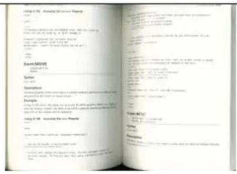
Before Shadow Removal
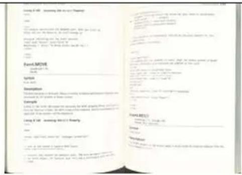
After Shadow Removal
Background Processing: The [Background Processing] option allows you to smooth background color or remove it to make image clearer. The option is especially useful for documents with color forms such as invoices.
Choices: None (default), Smooth, Removal
- None - no background processing will be performed (default)
- Smooth - produces images with a more uniform background color. This option improves image quality.
- Removal - identifies the background color and then removes it.
Sensitivity: Choice: 0, 1, 2, 3, 4. Default: 0
- The higher the value, the more background color will be kept.
Mode: Auto, Moiré
If [Smooth] is selected in the [Background Processing] option, then the choices for the [Mode] option includes Auto, and Moiré.
- Auto - uses the factory preprogrammed mode to proceed background smoothing.
- Moiré – Remove the moiré patterns that appear on the background of the image when scanning printed material.
If [Removal] is selected in the [Background Processing] option, then the [Mode] option will be replaced with [Fill Color]. Choices: White, Auto.
- White - identifies the background color and substitutes it with white.
- Auto - identifies the background color and substitutes it with the color of the largest background zone.
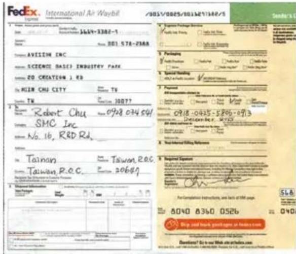
Background Processing: None
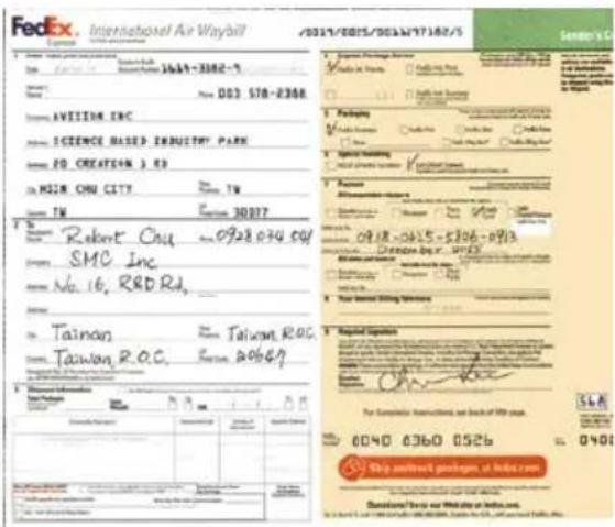
Background Processing: Smooth
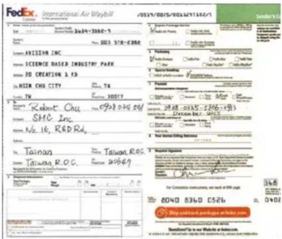
Background Processing:
Removal
Fill Color: White
Note: Background color in small zone will not be processed or removed.
Edge Fill
Check White or Black if you wish to add white or black edge on the border of your scanned image. Enter the value from 0 to 5 mm. Default value is 0.
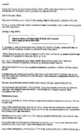
Original
Occasionally small dots or specks appear in the background of a scanned image. Remove unwanted speckles provides a cleaner image for OCR (Optical Character Recognition) processing, and also helps to reduce compressed file size.
Define the speckles (also known as image noise) you wish to remove by specifying its number (size) and radius (range). The measuring unit is pixel. The higher the number, the more speckles will be removed.
A plague on thee! Hast thou never an eye in thy head? Canst not hear?
—The First Part of King Henry the Fourth: 2.1.26–27
A carrier to Gadshill, the host of a tavern.
Before Despeckle
(noise number:0, noise radius:1)
A plague on thee! Hast thou never an eye in thy head? Canst not hear?
—The First Part of King Henry the Fourth: 2.1.26–27
A carrier to Gadshill, the host of a tavern.
After Despeckle
(noise number:22, noise radius:10)
Note:
- The function is currently available for Black and White image only.
- To scan at rated speed, it is recommended to set the noise radius up to 10 pixels.
Line Removal: When Black and White image mode is selected on the [Image] tab, the [Line Removal] option will be enabled. Line Removal erases lines on the image and then reconstructs characters so the OCR (Optical Character Recognition) accuracy can be improved.
Choices: None, Form, Horizontal, Vertical
None – the default mode which does not remove any line.
Form – remove any form in the document.
Horizontal – select [Horizontal] and then enter the length of horizontal line to remove only the horizontal line exceeding your specified length.
Vertical – select [Vertical] and then enter the length of vertical line to remove only the vertical line exceeding your specified length.
Ann. Mr. Brett Wang
| Marks & Nos. | Description of Goods | Quantity | Unit Price | Amount |
| ABC Seattle DVO No.1223 EBO 1 Hode in Talveen R.O.C. | A##net | Betn No. 1001) | 3 ozs | USD 20.00 | USD 60.00 |
| A##net | Betn No. 1011) | 3 ozs | USD 20.00 | USD 60.00 | |
| A##net | Betn No. 1021) | 3 ozs | USD 20.00 | USD 60.00 | |
| Total | 5 ozs | USD 20.00 |
A##: Mr. Daid Wang
| Stage of by SST Technologies Inc. | Per U-Line Express | ||||
| Sailing on or about | July 30, 2012 | From Taiwan, R.O.C. | to U.S.A. | ||
| L/C No. | Contract No. A1233 | ||||
| Varch & Kira | Description of Cada for | Quantity | Unit Price | Amount | |
| ABC | A##ret (Bata No. 100) | 3 sets | USD40.00 | USD40.00 | |
| A##ret (Bata No. 101) | 3 sets | USD40.00 | USD40.00 | ||
| A##ret (Bata No. 102) | 3 sets | USD40.00 | USD40.00 | ||
| Seattle PVON6 A1235(DN) | |||||
| Dada in TaiwanR.O.C. | |||||
| Total | 5 sets | US$80.00 | |||
None Remove Form
Adin Mr. David Wang
| Shipped by: SST Technologies Inc. | For | U-Line Express | ||
| Sailing on or about | July 30, 2012 | Braea Taiwan, R.O.C. | to | U.S.A. |
| L/C No. | Contract No. A1223 | |||
| Muster & Ste. | Description of Goods | Quantity | Unit Price | Amount |
| ABC | Ammaret (Bera No. 100) | 3 sets | USD10.00 | USD60.00 |
| Ammaret (Bera No. 101) | 3 sets | USD20.00 | USD60.00 | |
| Ammaret (Bera No. 102) | 3 sets | USD10.00 | USD60.00 | |
| Seattle P/O No. ALI233 LADs. 1 Mode in Europe R.O.C. | ||||
| Total | 5 sets | US$120.00 |
Aim:Mr.David Wang
| Shipped by SST Technologies Inc. | Per | U-Line Express | |||
| Sealing en or about | July 20, 2012 | Erons Taiwan, R.O.C. | to | U.S.A. | |
| L/C No. | Contract No. A1285 | ||||
| Marks & Nos. | Description of Goods | Quantity | Unit Price | Amount |
| ABC Seattle D/C No.: A1233 C/No. 1 Made in Taiwan R.O.C. | Amort.(Non Ho. 100) | 3 sets | USD20.00 | USD50.00 |
| Amort.(Non Ho. 101) | 3 sets | USD20.00 | USD50.00 | |
| Amort.(Non Ho. 102) | 3 sets | USD20.00 | USD50.00 | |
| Total | 5 sets | USD126.00 |
Remove Horizontal Line (over 30 mm)
Remove Vertical Line (over 70 mm)
4.10 The Rotation Tab
The Rotation tab allows you to set the following image rotating options:
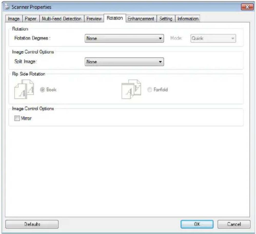
Rotate Image
Choose the rotation angle from the drop down list if you wish to rotate your scanned image.
Choice: None, 90° CW (clockwise), 90° CCW (counter clockwise), 180°, Auto based on contents. Auto rotate every even page.
1 2 3
123
Original
Rotate 90°CW
123
123
Rotate 90° CCW
Rotate 180°
Auto based on contents: Automatically rotate images based on the contents of document. When 'Auto based on
contents」is selected, its modes will be enabled to let you select more options.
Mode: Quick, Full Text, Complexity
Quick – the default mode to let you rotate images at the fastest speed.
Full Text – the enhanced mode for documents with mixed text orientation.
Complexity – the enhanced mode yet at the slowest speed for document with complex image or text orientation.
Auto rotate every even page:
Automatically rotate 180° on every even page. This is especially useful when you scan the inside pages from a book. As a result, if you choose “Flatbed (book)” from the “Scan Source” option, “auto rotate every even page” will be selected as default.
Note: This option varies based on type of scanner.
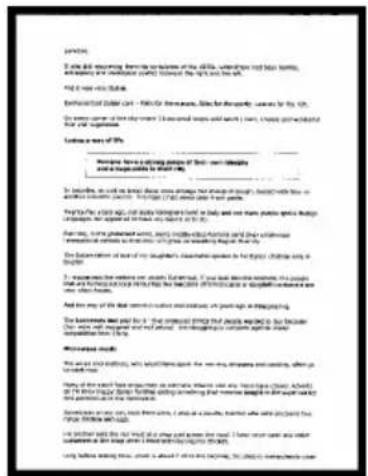
Document with various text orientations
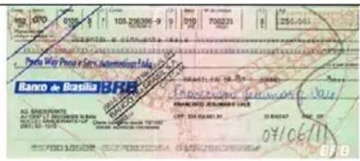
Document with dark or complex background
Split Image
By splitting an image, two separate images are created horizontally or vertically. This is useful for documents containing two pages per image when you want to save them as two images (one page for one image). Choice: None, Horizontal, Vertical. Default is None.
Horizontal: Divide one image into the upper half and the lower half.
Vertical: Divide one image into the left half and the right half.
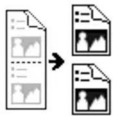
flowchart
graph TD
    A["File"] --> B["Image Conversion"]
    B --> C["Output Image 1"]
    B --> D["Output Image 2"]
Split Horizontally
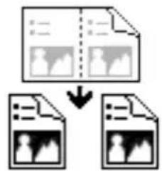
flowchart
graph TD
    A["Document Input"] --> B["Document Review"]
    B --> C["Document Review"]
    style A fill:#f9f,stroke:#333
    style B fill:#ccf,stroke:#333
    style C fill:#cfc,stroke:#333
Split Vertical
Flip Side Rotation
Select "fanfold" to rotate the image of the reverse side to 180 degrees.
This is applied to double-sided document which are viewed in portrait are sometime fed into the scanner in landscape or vice versa.
Choice: Book, Fanfold.
If "Book" is selected, the image of the reverse side will not be rotated.
The following illustration shows the documents which should be viewed in portrait are fed into the scanner in landscape
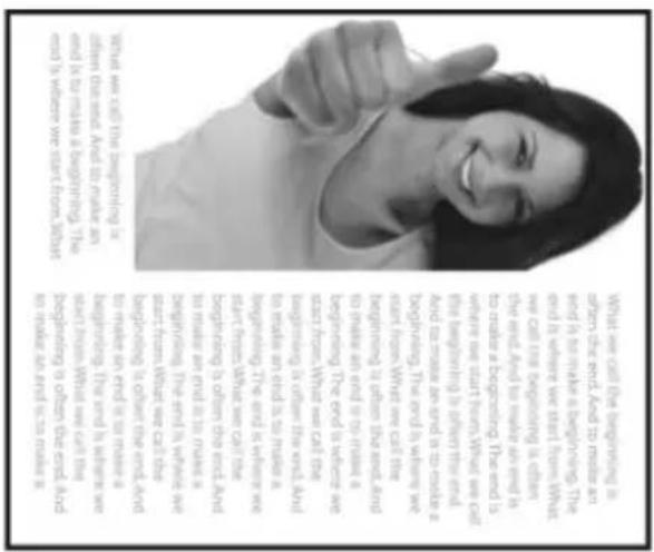
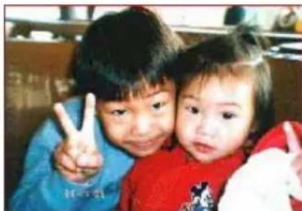
Image Control Option
Check the Mirror box if you wish to reverse the right and left side of your image.
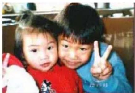
natural_image
Two children making peace signs together (no visible text or symbols)Original
natural_image
Two children making peace signs together, one adult and one child smiling (no visible text or symbols)The Mirror Effect
4.11 The Separation Tab
The Separation tab allows you to enable the detection engine to detect the blank page, barcode, and patch code and then notify the software application which supports document separation to separate your multi-page documents. Choices: Blank Page Removal, Barcode Detection, Patch Code Detection.
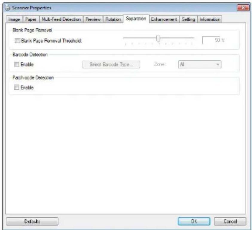
Blank Page Removal
Choices: None, Blank Page Removal Threshold, Image Size.
None – Do not remove the blank pages.
Threshold - Move the slider to the left or right to define your threshold for the blank page.
Image Size – Range: 1\~10000 KB. Specify your desired image size to detect the page as a blank page. For example, if 3 KB is selected, any page less than 3 KB will be recognized as blank page.
Barcode Detection
Check [Enable] to detect barcode and notify the software application for advanced processing. Please note the whole document will be checked and no specific detection area needs to be designated.
When the bar code has been detected successfully, a file [avbarcode.ini] will be created and stored in the following path:
Windows XP: C:\Documents and Settings\All Users\Application Data\% PRODUCTNAME%
Vista, Windows 7, Windows 8, Windows 10: C:\Program Data\% PRODUCTNAME%
Barcode Types: The following barcode types can be detected.
Two-dimensional codes
- Aztec
- DataMatrix
- PDF417
- QR Code
One-dimensional barcodes:
- Add-2
- Add-5
- Airline 2 of 5
• Australian Post 4-State Code - BCD Matrix
- Codabar
- Code 128 (A,B,C)
- Code 2 of 5
- Code 32
- Code 39
- Code 39 Extended
- Code 93
- Code 93 Extended
- DataLogic 2 of 5
EAN 128 (GS1, UCC)
EAN-13
• EAN-8
- GS1 DataBar
- Industrial 2 of 5
- Intelligent Mail (One Code)
- Interleaved 2 of 5
- Inverted 2 of 5
- ITF-14 / SCC-14
- Matrix 2 of 5
- Patch Codes
- PostNet
• Royal Mail (RM4SCC)
• UCC 128
- UPC-A
- UPC-E
Barcode Zone:
Specify the barcode zone to be detected.
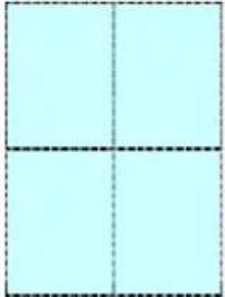
Select 「All」 to checks the whole document and detects barcodes. Or you may speed up the process by specifying a detection area since only the specified area is checked.
Choice: All, Top, Bottom, Left, Right, Bottom Right, Bottom Left, Top Right, Top Left
Choice for barcode zone on a page:
 All All | 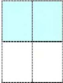 Top Top | 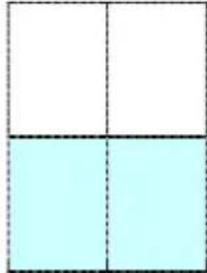 Bottom Bottom | 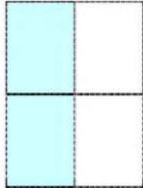 Left Left | 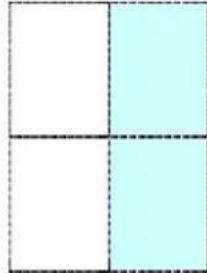 Right Right |
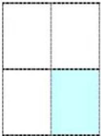 Bottom Right Bottom Right | 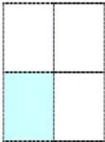 Bottom Left Bottom Left | 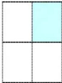 Top Right Top Right | 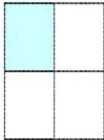 Top Left Top Left |
Note:
- Recommended resolution: 200\~600 dpi for regular barcode, 300\~600 dpi for QR code
- Skewed barcodes may not be recognized correctly.
- Using the same sheet repeatedly may decrease the recognition accuracy due to accumulated dirt on the sheets. If the sheet is not recognized correctly or gets smudged, replace it with a new sheet.
Patch code Detection:
Check [Enable] to detect patch codes and notify the software application for advanced processing.
A patch code is a pattern of parallel, alternating black bars and spaces (i.e. a barcode) that is printed on a document. Patch code sheet is most commonly used as a document separator in a stack of document.
You can find various sizes of patch codes (PDF) by choosing [Start] menu>[All Programs]>[Avision Scanner Series]>[Patch code] in succession.
Simply print the PDF file to produce the patch code sheet. Insert the patch code sheets to wherever you want the file to separate.
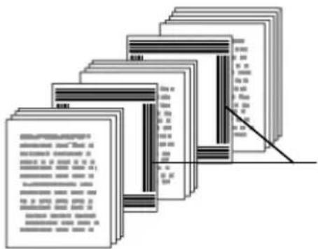
Patch code sheet
Notes to print the patch codes:
- Use blank white paper.
- Set the scaling to 100%. The sheet is not recognized correctly when printed in a size smaller than the original.
- Do not use toner saving mode. The sheet is not recognized correctly when the print is too light.
- Do not use thin paper in order to avoid bleed-through from the back.
- When you copy a patch code sheet that you printed out, make sure to copy by the same size and brightness as the original copy.
- Use the same sheet repeatedly may decrease the recognition accuracy due to accumulated dirt on the sheets. If the sheet is not recognized correctly or gets smudged, replace it with a new sheet.
4.12 The Setting Tab
The Setting tab allows you to set the following settings:
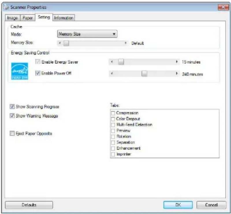
The Setting tab dialog box
| Energy Saving Control | Check the Enable Energy Saver box and move the slider to set the amount of time to start the energy saver after your last action. The range is from 1 to 60 minutes. |
| Enable Power Off | Check the Enable Power Off box and move the slider to set the amount of time to automatically turn off the scanner after your last action. The range is from 1 to 480 minutes. The default is 240 minutes (4 hours). Note the value of “Power Off” has to be greater than or equal to the value of “Energy Saving”. |
| Cache | Mode: None, Page Number, Memory Size.This option allows you to assign a specified memory size from the available RAM to process the image data. By specifying a smaller memory size, you can free more memory for other applications you are running. By specifying a larger memory size, you can have more memory to process the image data especially when you have a large amount of documents needed to be scanned.You can also specify your memory size by the page number. For your information, an A4 color document scanning at 300 dpi consumes approximates 24MB.Image CountWhen the selected cache mode is “none”, the image count option allows you to assign number of pages you need to scan. For example, if you wish to scan the first two pages, simply move the page slider to 2, and the scan action will be stopped when the scanning of the first two pages have been completed. |
| Show Scanning Progress | Check and the scanning progress bar will be shown during scanning. |
| Show Warning Message | Check to show the warning messages such as “ADF pad count exceeds 50,000 scans (the number varies based on type of scanner). Please replace the ADF pad and reset the pad count.” |
| Save Settings after Closing | Check to save your scanner properties settings after leaving the dialog box. Next time when you open the Scanner Properties dialog box, the previously saved settings will be shown. |
4.13 The Imprinter Tab
The Imprinter tab allows you to print alphanumeric characters, date, time, document count and custom message on your scanned image if digital imprinter is selected or at the back of your document if external imprinter is selected.
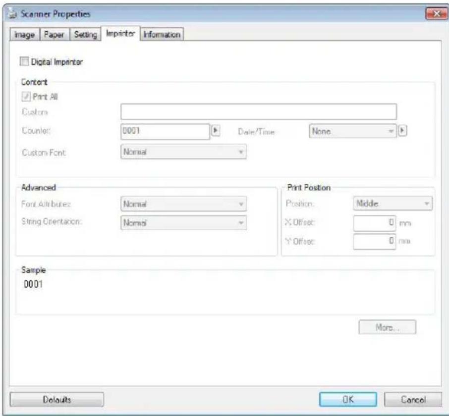
Choice: External Imprinter, Digital Imprinter. If you have installed an external imprinter, choose external imprinter. If you do not have an imprinter, choose digital imprinter. Note External Imprinter provides a vertical and rear-side print capability while digital printer provides a horizontal and front-side print capability.
Contents
| Print All | Check Print All to automatically print the text at all pages of your documents. Uncheck Print All to print the text for the first page of your documents only. |
| Custom | Enter your custom text to be included in your print string. |
| Counter | Show the document count for the scan session. This value is increased sequentially by the scanner. |
| Date/ Time | Choose if you wish to include the date and time in your print string.Format: YYYYMMDDHHSS For example, 20090402170645-check0001 indicates year, month, date, hour, seconds, your custom text and the counter. |
| Custom Font | Choose your desired font.Choice: Normal, Fixed WidthFixed Width (Mono spaced) fonts have a fixed character spacing. So each character occupies the same width. |
Advanced
| Font Attributes | Choose your font attributes. Choice: Normal, Underline, Double, and Bold. | |
| String Orientation | Choose your string orientation.Choice: Normal, Rotated, Vertical,Vertical Inversion, 90 degrees CW, 90degrees CCW | |
| 2010abcNormal | 2010abcRotated | |
| 2010abcVertical | 2010abcVertical Inversion | |
| 2010abc90 degrees CW | 2010abc90 degrees CCW | |
| If you check the digital imprinter to stamp text on your scanned image, the illustration of normal and rotated string is shown below: | ||
| 2010abcNormal | 2010abcRotated | |
| Print Position | Choose the position you wish to print your string. Move the slider to the right to increase the value or to the left to decrease the value. Range: 0~355mm, default:0 mm The value indicates the height from the bottom of your paper to the last letter of your string. This option is available only if an external imprinter is installed.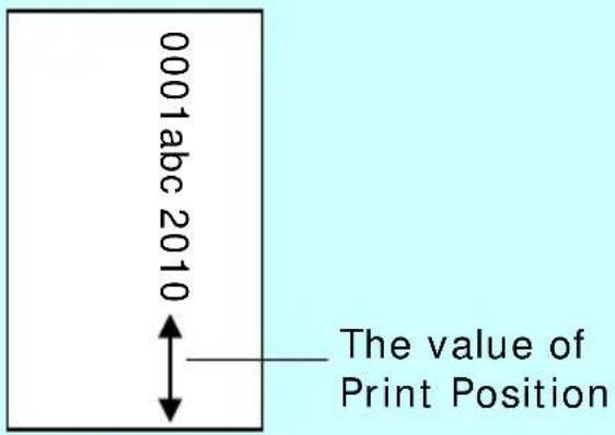 | |
Print Position (for digital imprinter)
Choose the position of your printed string. Choice: Top, Middle, Bottom, Custom. If Custom is selected, enter the X and Y offset value to specify the position.
4.14 The Information Tab
The Information tab displays the following system and scanner information.
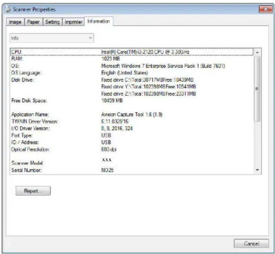
The Information tab dialog box
The "Report" button :
If you encounter any error message while using the scanner, click the Report button. A report.txt file [Windows XP: C:\Documents and Settings\All Users\Application Data\%PRODUCTNAME%; Vista, Windows 7, Windows 8, Windows 10: C:\ProgramData\%PRODUCTNAME% (C: system drive)] will be generated. Please send this file to the nearest service center for trouble shooting.
The "Reset Roller Count" button :
After scanning over a recommended number of pages (refer to subsequent section 7.4 Replacing the ADF Roller) through the ADF, the ADF roller may be worn out and you may experience problems with document feeding. In this case, it is highly recommended to replace the ADF roller with a new one. (Note the replacement of the ADF roller has to be performed only by authorized service center. Therefore, please return your scanner for roller replacement.) After replacing the ADF roller, click the “Reset Roller Count” button to reset the roller count.
Note :
The lifetime and the replacing procedure vary based on type of scanner.
5. ISIS Interface Operation
* Please refer to the preceding chapter, Scanner Installation, to install ISIS scanner driver. You may start your ISIS-compliant software application to scan via the ISIS user interface.
The ISIS driver operation method is similar to the TWAIN's. Every function on the ISIS interface screen is briefly described as below:
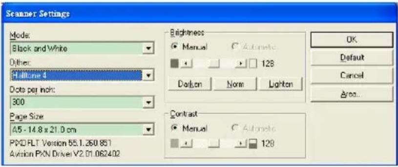
Mode: Select one of scan modes, including B&W, gray, color options.
Dither: 5 halftone levels available, can be disabled.
Dots per inch: Select your desired resolution.
Paper Size: Select your desired paper size.
Brightness: Adjust your scan image brightness or darkness.
Contrast: Adjust the range between the darkest and the lightest shades in the image.
Default: Click to reset all settings.
Area: Select your desired scan area or position.
6. Using the Buttons
The following picture shows the 4 buttons and 1 function screen on the scanner.
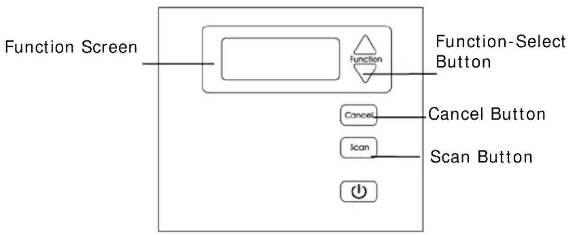
flowchart
graph TD
    A["Function Screen"] --> B["Function"]
    B --> C["Function-Select Button"]
    B --> D["Cancel"]
    B --> E["Scan"]
    B --> F["Power Button"]
6.1 Installing Button Manager V2
Button Manager V2 provides you an easy way to scan your document and then link the scanned image to your designated software application. All this can be done by a simple touch of the button on the scanner. Yet, before you scan, it is recommended to check the button configurations first to ensure a proper file format and a destination application.
6.2 Checking the Button Configurations before Scanning
- Button Manager V2 runs from the system tray. After Button Manager V2 and the scanner driver are properly installed, Button Manager V2 is started and the Button icon will be displayed on the system tray at the bottom right corner of your computer screen.
01:41 PM
- Left-click the Button Manager V2 icon to prompt the following Button Panel.
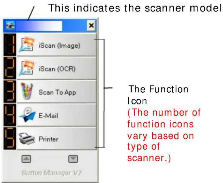
The Button Panel
- The Button Panel shows the first five scanning buttons. Right-click the button (function) you wish to check. The Button Properties window appears.
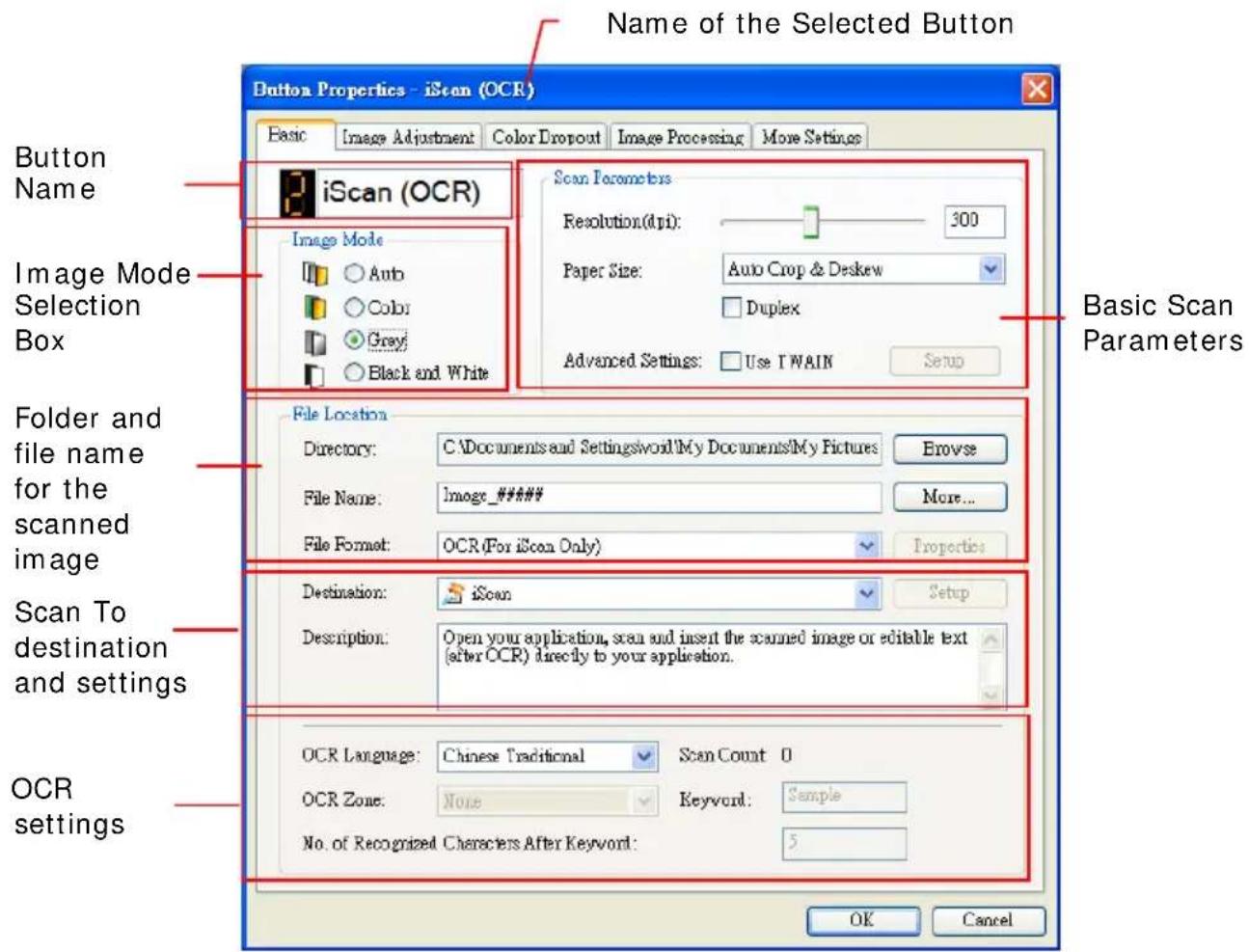
If you wish to change the setting, use this window to reset the setting for the file format, destination application, or other scan settings.
- Click the OK button to leave the window.
6.3 Scanning From One Touch of the Buttons
- Adjust the paper guide for the width of paper and load the document with their tops into the automatic document feeder.
- Check the button name on the LCD screen to ensure if you are selecting the proper scan settings and destination application. (For example, if you wish to scan with Button, "Scan to App", which opens Microsoft Paint and displays the scanned image in the window of Microsoft Paint, the LCD screen should show "Scan to App").
- Press the Scan button on the scanner.
- After the scanning is finished, the Microsoft Paint software will be launched and the scanned image appears in the main window of Microsoft Paint as below.
| General Specifications: | Document feeding mode | Flatbed |
| Technology | ||
| Optical resolution | ||
| Scanning speed | ||
| RAM | ||
| ADF min. paper size | 4.5 inch | |
| ADF max. paper size | 8.5 inch | |
| Flatbed mix. paper size | 8.5 inch : | |
| ADF capacity | ||
| Operation environment | 10 | |
| Storage environment | -20 | |
| Noise | ||
| Dimensions(H x W x D) | ||
| Weight | ||
| Copy Specifications: | First copy out | Color mode |
| Color copy speed | ||
| B/W copy speed | ||
| Copy resolution | ||
| Copy scaling | ||
| Multiple copies |
Note:
- For details information on how to use the Button Manager V2, please refer to the user's manual in the supplied CD.
- You may also use Button Manager V2 on your desktop by starting Button Manager V2 from All Programs or double clicking the Avision Scanner Utility from the Control Panel.
7. Maintenance
7.1 Cleaning the ADF
From time to time, the Reverse roller and the Feeding Rollers may be contaminated with ink, toner particles, or paper dust. In this case, the paper may not be fed smoothly. Please follow the following steps to clean the Reverse roller and the Feeding Rollers to ensure the best of the scanner.
The Cleaning Steps:
- Soak a clean cloth with some isopropyl alcohol (95%).
- Press the ADF release button and open the front door.
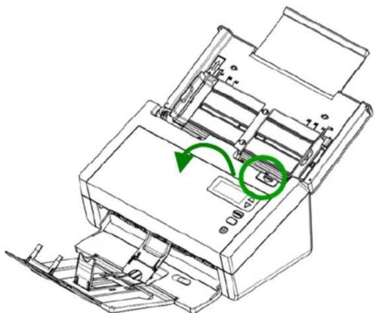
natural_image
Line drawing of a printer with a green circular arrow indicating rotation or adjustment (no text or symbols present)- Wipe the feeding rollers until they are cleaned.
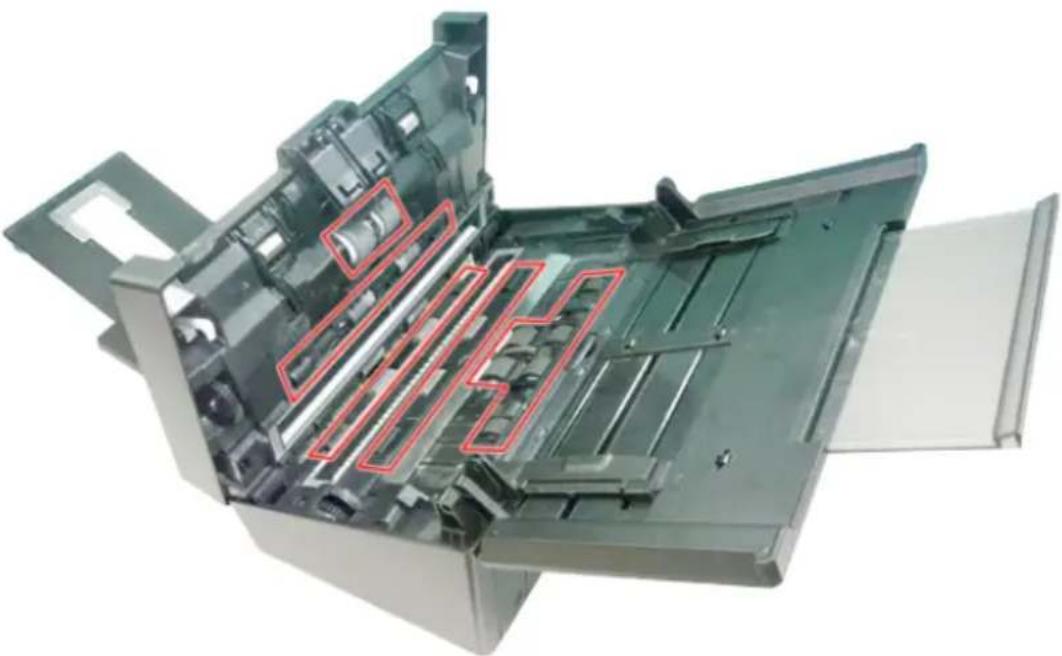
natural_image
Interior view of a computer printer showing internal components and casing (no text or symbols visible)- Press both sides of the cover of the ADF reverse roller and pull the cover down.
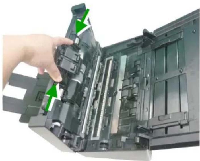
natural_image
Close-up of a hand inserting a component into an open computer case, showing internal structure and green directional arrows (no text or symbols visible)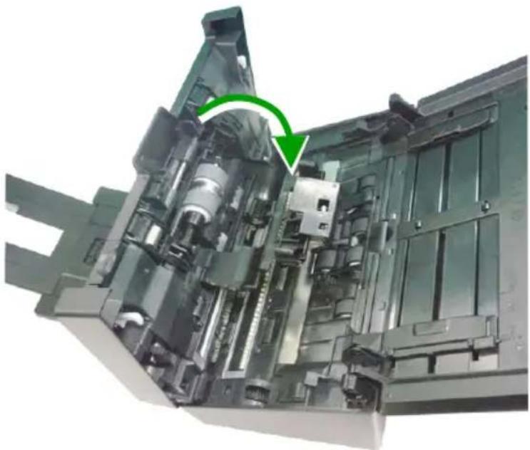
natural_image
Close-up of a mechanical device interior showing internal components and a green arrow indicating a specific part (no text or symbols visible)- Press and wipe the rollers one by one. Rotate the roller until the surfaces are completely cleaned.
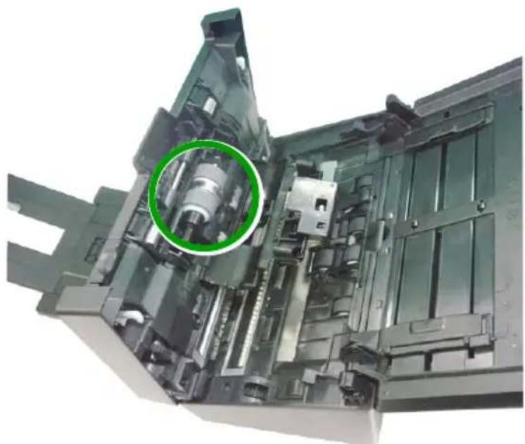
natural_image
Internal view of a mechanical device with a highlighted cylindrical component (no visible text or symbols)7.2 Cleaning the Glass
- Press the ADF release button. Open the front door.
- Wet a clean cloth with some isopropyl alcohol. (95%)
- Wipe the glass as illustrated below by moving the swab from side to side to rid the dust or dirt.
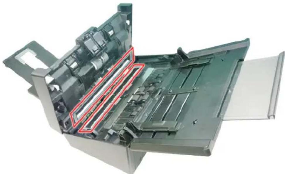
natural_image
Interior view of an open printer with visible internal components and a red outline highlighting a specific area (no text or symbols present)7.3 Replacing the ADF Reverse Roller
After scanning approximately 100,000 pages through the ADF, the reverse roller will be worn out and you may have problems with document feeding. It is time to replace the Reverse roller. For ordering the replacement, please contact your dealer.
Disassembling Procedure
- Press the ADF release button.
- Gently open the ADF front door to the left.
- Hold the reverse roller cover with your fingers as shown and place it down.
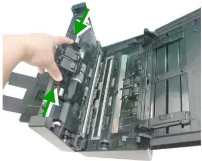
natural_image
Close-up of a hand inserting a component into an open electronic device (no visible text or symbols)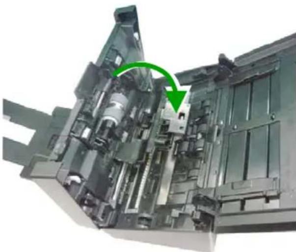
natural_image
Close-up of a mechanical assembly with green arrows indicating a component or process (no visible text or symbols)- Press the right end of the reverse roller externally to detach it from the slot and then detach the left end from its hole.
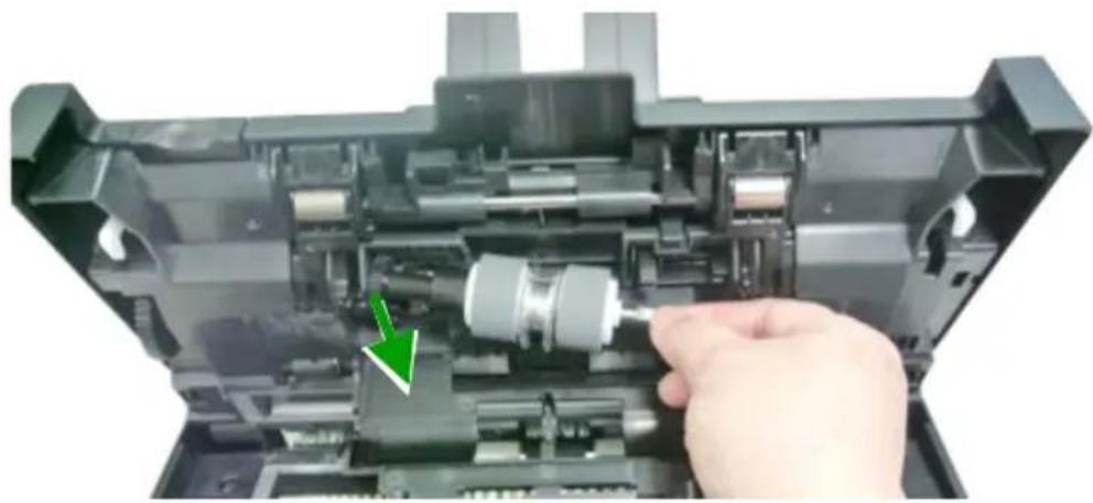
natural_image
Close-up of a hand inserting a plastic component into a device casing (no visible text or symbols)Reassembling Procedure
-
Insert the left end of the reverse roller to the hole of its original place.
-
Insert the right end of the reverse roller to its slot.
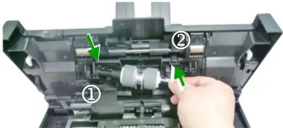
- Close the reverse roller Cover.
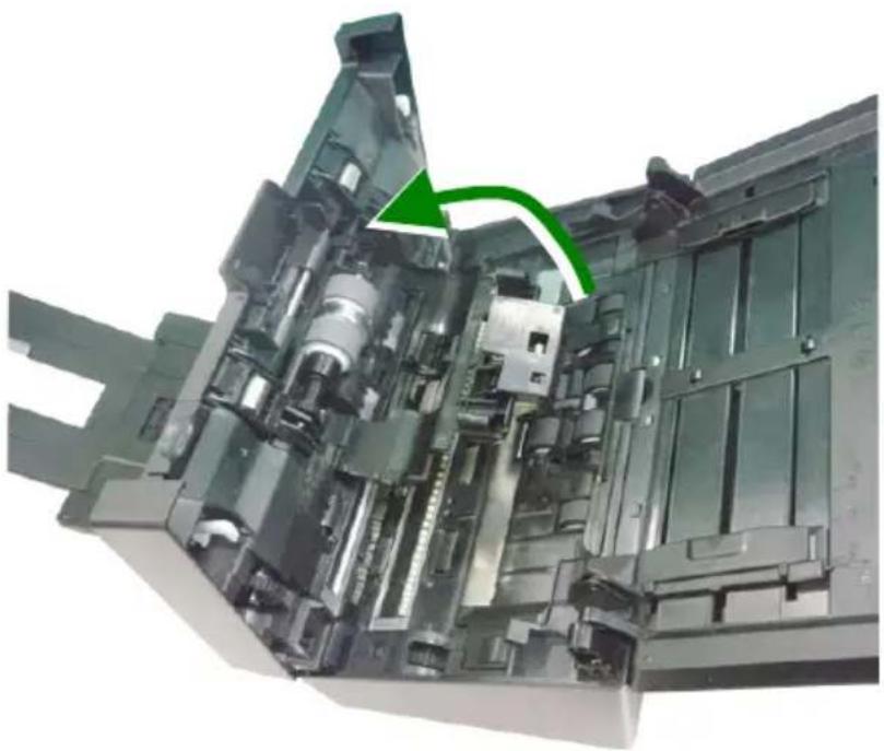
natural_image
Cross-sectional view of a mechanical device showing internal components and a green arrow indicating a specific part (no text or symbols present)- Close the ADF cover.
7.4 Replacing the ADF Rollers
After scanning approximately 200,000 pages through the ADF, the ADF roller may be worn out and you may experience problems with document feeding. In this case, you may need to replace a new ADF roller. For ordering the ADF roller, please consult your nearest dealer and follow the procedure below to replace it.
Disassembling Procedure
- Press the ADF release button to open the front door.
- Pull the center of the roller cover to open it.

natural_image
Hand pressing down on a printer's internal circuit board with a green arrow indicating the process (no text or symbols visible)- Move the tab of the ADF roller DOWN as indicated.
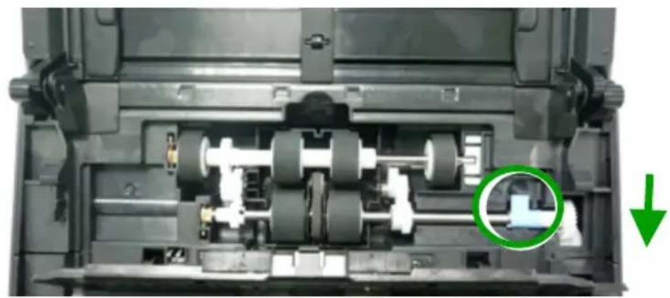
natural_image
Internal view of a mechanical device showing internal gears and shafts, with a green circular annotation highlighting a component (no text or symbols present)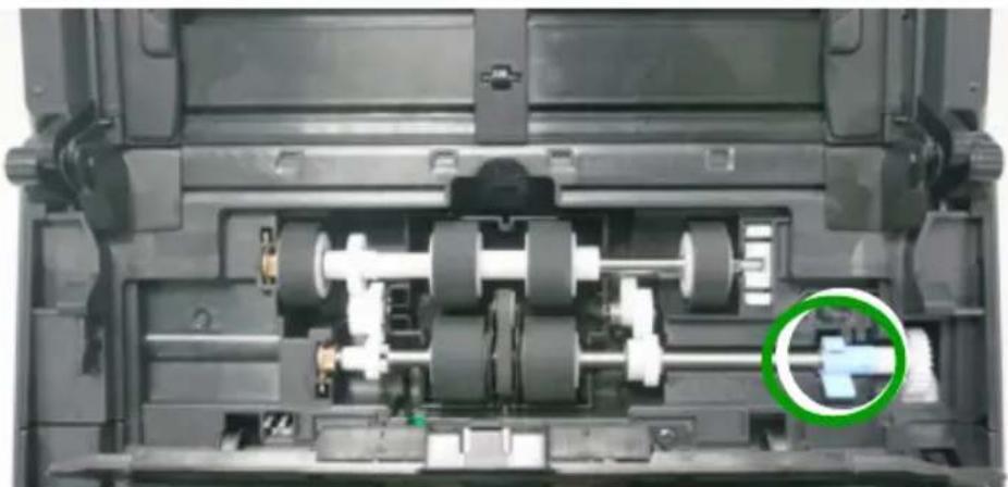
natural_image
Interior view of a mechanical device showing internal gears and shafts (no visible text or symbols)- Detach the right end of the ADF roller from the scanner and remove the ADF roller.
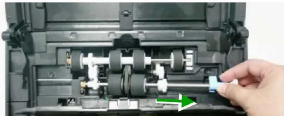
natural_image
Close-up of a mechanical device showing internal gears and shafts, with a hand adjusting a component (no visible text or symbols)Assembling Procedure
- Insert the left end of the ADF roller first to its slot and place the ADF roller to its proper position.
Make sure the belt in the center of the lower ADF roller is installed horizontally with the other rollers as indicated.
The Belt
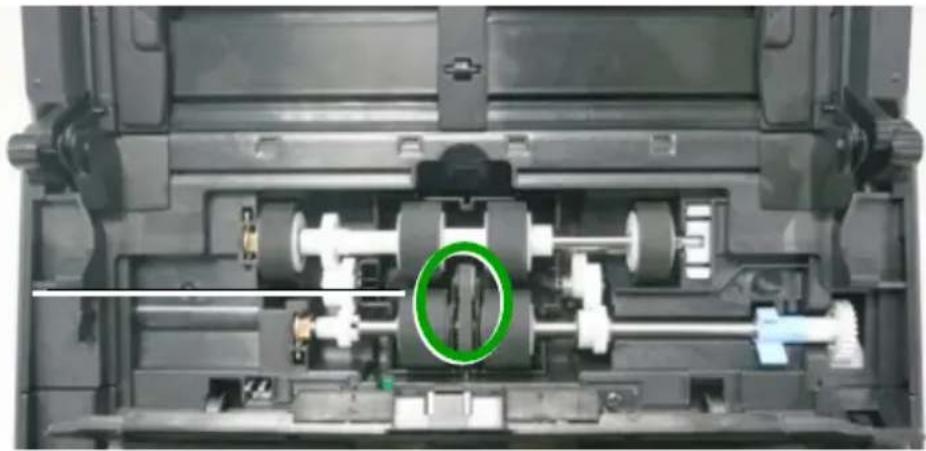
natural_image
Interior view of a mechanical device showing internal gears and shafts (no visible text or symbols)- Move the tab of the ADF roller UP.
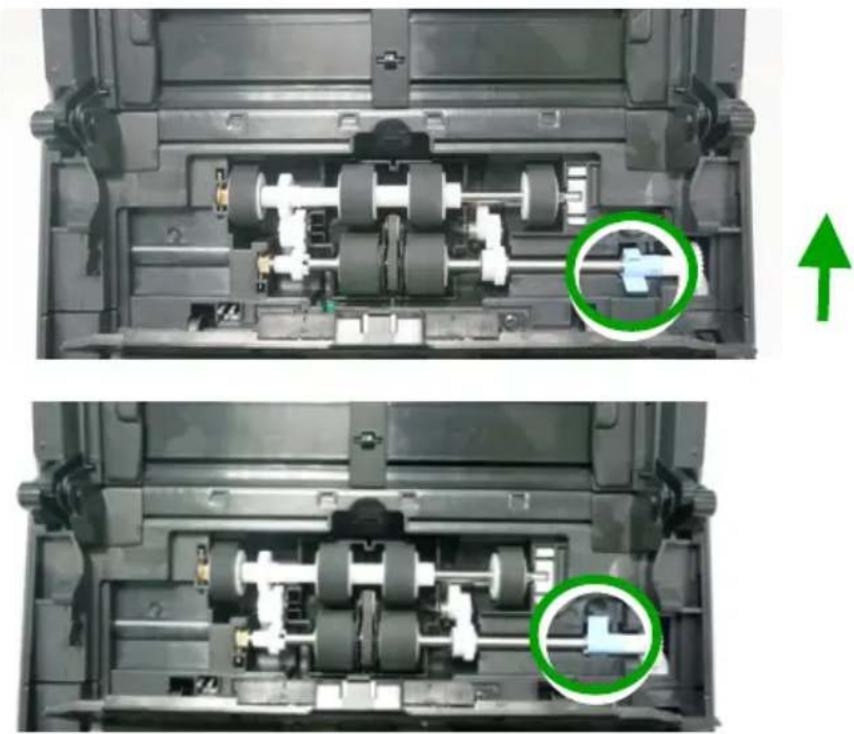
natural_image
Two views of a mechanical device showing internal components and a green arrow indicating upward motion (no text or symbols present)- Close the ADF roller cover. A snap-in sound could be heard if correctly installed.
8. Troubleshooting
8.1 Clearing a Paper Jam
In the event of a paper jam, follow the procedures below to remove the paper:
- Press the ADF release button on the right side. Gently open the front door.
- Carefully pull the paper out of the ADF unit.
- Close the front door. Your Scanner is now ready to use.
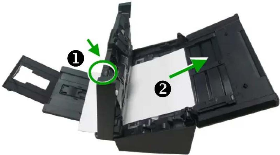
8.2 Questions and Answers
| Question: | Paper becomes jammed during scanning. |
| Answer: | 1) Open the front door.2) Pull out the jammed paper carefully.3) Close the front door. |
| Question: | More than one sheet of paper are fed into the scanner. |
| Answer: | 1) Open the scanner front door.2) Remove the multi-fed sheets.3) Close the front door.4) Flatten the corners and edges. Loosen the paper before putting it into the paper guide again.5) Check the feeding roller condition. If necessary, follow the cleaning directions in section 7.1 and perform the cleaning. |
| Question: | Paper becomes skewed in the scanner. |
| Answer: | 1) Use the slide guide to keep the paper path straight.2) Check the condition of the feeding roller. If necessary, follow the cleaning directions in Section 7.1 and perform the cleaning. |
Question: Why does my scanned image always come out too dark?
Answer:
1) Please adjust the screen settings to sRGB.
2) Please adjust the brightness settings on the screen from application software.
Question:
When I choose optical resolution to be 600 dpi, the "auto crop" and "deskew" functions will be disabled.
Answer:
Since to perform auto crop and deskew consumes great deal of system memory, it is suggested if you wish to perform "auto crop" and "deskew" functions, please choose your optical resolution to be smaller than 600 dpi to prevent a error message.
8.3 Technical Service
Before contacting Avision, please prepare the following information by referring to Section 4.14, The Information Tab:
- Scanner serial & revision number (located on the bottom of the scanner);
■ Hardware configuration (e.g., your host CPU type, RAM size, free disk space, display card, interface card);
■ The name and version of your scanning software application;
■ The version of your scanner driver.
Please call us at:
Headquarter
Avision Inc.
No. 20, Creation Road I, Science-Based Industrial Park,
Hsinchu 300, Taiwan, ROC
TEL: +886 (3) 578-2388
FAX: +886 (3) 577-7017
E-MAIL: service@avision.com.tw
Web Site: http://www.avision.com.tw
US and Canada Area
Avision Labs, Inc.
6815 Mowry Ave., Newark CA 94560, USA
TEL: +1 (510) 739-2369
FAX: +1 (510) 739-6060
E-MAIL: support@avision-labs.com
Web Site: http://www.avision.com
China Area
Hongcai Technology Limited
7A, No.1010, Kaixuan Road, Shanghai 200052 P.R.C.
TEL :+86-21-62816680
FAX :+86-21-62818856
E-MAIL :sales@avision.net.cn
Web Site:http://www.avision.com.cn
Europe Area
Avision Europe GmbH
Bischofstr. 101 D-47809 Krefeld Germany
TEL: +49-2151-56981-40
FAX: +49-2151-56981-42
E-MAIL: info@avision-europe.com
Web Site: http://www.avision.de
Espaço Brasil
Avision Brasil Ltda.
Avenida Jabaquara, 2958 - Cj. 75 - Mirandópolis –
All specifications are subject to change without notice. For the most up-to-date and detailed specifications, please refer to our web site at http://www.avision.com
Model Number : FL-1315B/FL-1314B
Optical Resolution: 600 dpi
Output Resolution: 72\~1200 dpi (adjustable in 1 dpi increments)
Scanning Modes: Black & White / Gray / Color
ADF Capacity: Up to 100 pages (75 g/m 2 ) (20 lb.)
Max. Document Size: 242 x 356 mm (9.5 x 14 in.)
Min. Document Size: 50 x 50 mm (2 x 2 in.)
Paper Weight: 27 \~ 413 g/m 2 (7\~110 lb.)
ID Card Thickness: < 1.25 mm (0.05 in.)
Interface: Hi-speed USB 3.0
Power Source: 24V, 2.0A
Operating Temperature: 10° C\~ 35° C
Dimensions: (WxDxH)
Min. 316 x 191 x 168 mm
(12.4 × 7.5 × 6.6 in.)
Max. 316 x 680 x 239 mm
(12.4 × 26.8 × 9.4 in.)
Weight: 4.7 kg (10.4 lb.)
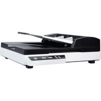
- Trademarks
- Copyright
- Warranty
- Federal Communications Commission (FCC) compliance information statement
- Part 15
- CE
- European Union Regulatory Notice
- Disposal of Waste Equipment by Users in Private Union
- System Requirements
- Product Safety Guide
- WARNING
- CAUTION:
- Introduction
- Package Items
- Note:
- Front View
- Rear View
- Scanner Installation
- Precautions
- Installing the Scanner Driver and Connecting the Cables
- Connecting to Power
- Before connecting, make sure the power switch is off.
- Turning on the Power
- Installing the Scanner Driver
- Contents on the installation graphic:
- Connecting to Computer
- Completing Your First Scan
- Loading Your Paper
- Notice on Using the ADF
- Loading Your Document in the ADF Paper Tray
- Fanning Your Document
- Document Feeding
- Scanning Thin Paper
- Scanning a Stack of Document with Various sizes and Weights
- Verifying Your Scanner Installation
- A Glance of the Scanner Properties Dialog Box
- Using the Scanner Properties Dialog Box
- Buttons on the Scanner Properties Dialog Box
- The buttons on the Scanner Properties dialog box
- Showing or Hiding Tabs
- The Image Tab
- The Image Selection Box
- Example 1 : Scanning a two-sided color document, both sides in color
- Example 2 : Scanning a two-sided color document, one in B&W, the other in color
- Front/ Rear Auto Color Detection:
- Modes of Auto Color Detection:
- Sensitivity of Auto Color Detection
- Original
- Same settings on both sides:
- Other Image Options
- Binarization
- Sensitivity of Dynamic Threshold
- Gray
- Document Type: Choice: Normal, Photo, Document
- Brightness
- Contrast
- Invert
- "I am not worthy to have you enter my
- Black on White
- White on Black
- Scan Source
- Choice:
- Color Matching
- Choice: None, Document, Photo
- Scanning color images
- Scanning grayscale images
- Scanning B&W images
- Editing Profiles
- To add a new profile,
- To load a profile,
- To delete a profile,
- To rename a profile,
- The Compression Tab
- Compression:
- To Application:
- From Scanner: (Note: The availability of this feature varies due to scanner model.)
- The Color Dropout Tab
- Color Dropout Selection
- Choice: None, Auto, Remove Red, Remove Green, Remove Blue, Custom
- Advanced Options:
- The Paper Tab
- Cropping
- Relative to Document: (used for batches of same-sized documents)
- A Cross Sign
- Other Paper Selection
- Carrier Sheet Mode:
- Loading Documents Using a Carrier Sheet
- To scan document using a Carrier Sheet,
- For documents larger than A4/ Letter size, such as A3
- Open the Carrier Sheet and place the document inside.
- For non-standard document
- Notice:
- Scan Area
- Long Page (<118"):
- Notice when scanning long page document:
- OverScan
- Pre-Feed
- Transport Timeout
- Background Setting
- The Multi-Feed Detection Tab
- Multi-Feed Detection
- Additional Length Detection
- Ultrasonic Detection
- - Stop Scanning after Multi-Feed
- - Multi-Feed Alarm
- How to add the sound alarm :
- Units
- The Preview Tab
- The Enhancement Tab
- Punch Hole Removal
- Punch holes can not be removed when:
- Shadow Removal
- Choices: None (default), Smooth, Removal
- Sensitivity: Choice: 0, 1, 2, 3, 4. Default: 0
- Mode: Auto, Moiré
- 100% Flight Passes and Passes
- Edge Fill
- Choices: None, Form, Horizontal, Vertical
- None Remove Form
- Remove Horizontal Line (over 30 mm)
- Remove Vertical Line (over 70 mm)
- The Rotation Tab
- Rotate Image
- Mode: Quick, Full Text, Complexity
- Auto rotate every even page:
- Split Image
- Flip Side Rotation
- Choice: Book, Fanfold.
- The Separation Tab
- Blank Page Removal
- Barcode Detection
- Two-dimensional codes
- One-dimensional barcodes:
- Barcode Zone:
- Choice for barcode zone on a page:
- Patch code Detection:
- Notes to print the patch codes:
- The Setting Tab
- The Imprinter Tab
- Print Position (for digital imprinter)
- The Information Tab
- The Information tab dialog box
- The "Report" button :
- The "Reset Roller Count" button :
- Note :
- ISIS Interface Operation
- Using the Buttons
- Installing Button Manager V2
- Checking the Button Configurations before Scanning
- Scanning From One Touch of the Buttons
- Maintenance
- Cleaning the ADF
- The Cleaning Steps:
- Cleaning the Glass
- Replacing the ADF Reverse Roller
- Disassembling Procedure
- Reassembling Procedure
- Replacing the ADF Rollers
- Assembling Procedure
- Troubleshooting
- Clearing a Paper Jam
- Questions and Answers
- Question: Why does my scanned image always come out too dark?
- Answer:
- Question:
- Technical Service
- Headquarter
- Avision Inc.
- US and Canada Area
- Avision Labs, Inc.
- China Area
- Hongcai Technology Limited
- Europe Area
- Avision Europe GmbH
- Espaço Brasil
- Avision Brasil Ltda.
Brand : AVISION
Model : AD260
Category : Scanner