
Modus (2008) - Car RENAULT - Free user manual and instructions
Find the device manual for free Modus (2008) RENAULT in PDF.


| Type | Compact MPV |
| Manufacturer | Renault |
| Model | Modus (2008) |
| Body style | 5-door MPV |
| Engine options | 1.2L I4 petrol (75 hp), 1.5L I4 diesel (68 hp) |
| Transmission | 5-speed manual or 5-speed automated manual |
| Dimensions (L x W x H) | 3799 x 1695 x 1589 mm |
| Wheelbase | 2482 mm |
| Kerb weight | 1100 - 1200 kg (depending on engine) |
| Fuel consumption (combined) | 5.6 - 6.2 L/100 km (depending on engine) |
| Fuel tank capacity | 49 L |
| Seating capacity | 5 |
| Safety features | ABS, EBD, front and side airbags, Isofix |
| Maintenance interval | Every 30,000 km or 2 years (oil change every 15,000 km) |
| Steering | Electric power steering |
| Brakes | Front ventilated discs, rear drums |
| Tire size | 185/65 R15 (standard) |
| Battery type | 12V, 60Ah |
| Oil type | 5W-30 or 5W-40 (depending on engine) |
| Coolant | Pre-mix type D (Radiator fluid) |
Frequently Asked Questions - Modus (2008) RENAULT
User questions about Modus (2008) RENAULT
0 question about this device. Answer the ones you know or ask your own.
Ask a new question about this device
Download the instructions for your Car in PDF format for free! Find your manual Modus (2008) - RENAULT and take your electronic device back in hand. On this page are published all the documents necessary for the use of your device. Modus (2008) by RENAULT.
USER MANUAL Modus (2008) RENAULT
A passion for performance

ELF, partner of
world
series
bag RENAULT


RENAULT recommends ELF
Partners in cutting-edge automotive technology, Elf and Renault combine their expertise on both the racetrack and the city streets. This enduring partnership gives drivers a range of lubricants perfectly suited to Renault cars. Lasting protection and optimum performance for your engine – guaranteed. Whether changing the oil or simply topping up, to find the approved ELF lubricant best suited to your vehicle, ask your Renault dealer for a recommendation or consult your vehicle maintenance handbook.
www.lubricants.elf.com

A brand from TOTAL
Welcome to your new vehicle
This Driver's Handbook contains the information necessary:
- for you to familiarise yourself with your vehicle, to use it to its best advantage and to benefit fully from all the functions and the technical developments it incorporates.
- to ensure that it always gives the best performance by following the simple, but comprehensive advice concerning regular maintenance.
- to enable you to deal quickly with minor faults not requiring specialist attention.
It is well worth taking a few minutes to read this handbook to familiarise yourself with the information and guidelines it contains about the vehicle and its functions and new features. If certain points are still unclear, our Network technicians will be only too pleased to provide you with any additional information.
The following symbol will help you when reading this handbook:

To indicate a hazard, danger or safety recommendation.
The descriptions of the models given in this handbook are based on the technical specifications at the time of writing. This handbook covers all items of equipment (both standard and optional) available for these models but whether or not these are fitted to the vehicle depends on the version, options selected and the country where the vehicle is sold.
This handbook may also contain information about items of equipment to be introduced later in the model year.
Throughout the manual, the "approved Dealer" is your RENAULT Dealer.
Enjoy driving your new vehicle.
Translated from French. Copying or translation, in part or in full, is forbidden unless prior written permission has been obtained from the vehicle manufacturer.
0.1

CONTENTS
Sections
Getting to know your vehicle ....
1
Driving
2
Your comfort ....
3
Maintenance
4
Practical advice ....
5
Technical specifications ....
6
Alphabetical index ....
7
Section 1: Getting to know your vehicle
Radio frequency remote control unit: general information, use, deadlocking 1.2
Doors.... 1.7
Automatic locking of opening elements when driving 1.11
Engine immobiliser system 1.12
Headrests - Seats 1.13
Seat belts. 1.16
Additional methods of restraint 1.20
to the front seat belts 1.20
to the rear seat belts 1.24
Additional methods of side restraint 1.25
Child safety: general information.... 1.27
Choosing a child seat mounting 1.30
Fitting a child seat 1.32
Deactivating/activating the front passenger airbag 1.38
Steering wheel. 1.41
Driving position 1.42
Instrument panel 1.46
On-board computer 1.52
Information displays.... 1.61
Clock and exterior temperature.... 1.62
Rear-view mirrors 1.64
Audible and visual signals 1.66
Exterior lighting and signals 1.67
Headlight beam adjustment 1.72
Washers/Wipers 1.73
Fuel tank (filling with fuel) 1.76
1.1
KEY/RADIO FREQUENCY REMOTE CONTROL: general information (1/2)
26565 A
Key A
1 Coded key for ignition switch, doors and fuel filler cap.
The key must not be used for any function other than those described in the handbook (removing the cap from a bottle, etc.).
B
Radio frequency remote control unit B or C
1 Locking the doors and tailgate. 2 Unlocking the doors and tailgate. 3 Driver's door and ignition key.
102A 27415 ©
4 Locking/unlocking the tailgate only. 5 To release the key from its housing, press button 5. It will be released automatically.
To reinsert it in its housing, press button 5 and guide the key into the storage position.
Advice
Avoid leaving the remote control in hot, cold or humid areas.
KEY/RADIO FREQUENCY REMOTE CONTROL: general information (2/2)
Radio frequency remote control operating range
This varies according to the environment: take care not to lock or unlock the doors by inadvertently pressing the buttons on the remote control.
Interference
The presence of certain objects (metal objects, mobile telephones, or an area with strong electromagnetic radiation, etc.) close to the key may create interference and affect the operation of the system.

Driver's responsibility
Never leave your vehicle with the key inside and never leave a child (or a pet) unsupervised, even for a short while.
They may pose a risk to themselves or to others by starting the engine, activating equipment such as the electric windows or by locking the doors.
Risk of serious injury.
For replacement, or if you require an additional remote control.
You must only contact an approved Dealer.
- To replace a remote control, the vehicle must be taken to an approved Dealer as both the vehicle and the remote control are needed to initialise the system.
- Depending on the vehicle, you have the option of using up to four remote controls.
Remote control unit failure
Make sure that the correct battery type is being used, and that the battery is in good condition and inserted correctly. These batteries have a service life of approximately two years.
Refer to the information on the "Key, radio frequency remote control: batteries" in Section 5 for the battery changing procedure.
RADIO FREQUENCY REMOTE CONTROL: use (1/2)

Unlocking the doors
Remote control A or B
Press unlocking button 2.
The hazard warning lights and indicator lights flash once to indicate that the doors have unlocked.

Special notes (for some countries):
- pressing button 2 enables the driver's door only to be unlocked,
- the other doors can be unlocked by pressing button 2 twice.
The key must not be used for any other function than those described in the handbook (removing the cap from a bottle, etc.).
RADIO FREQUENCY REMOTE CONTROL: use (2/2)
A 102A
Locking the doors
Remote control A or B
Press locking button 1.
The indicator lights and hazard warning lights flash twice to indicate that the doors have locked:
If a door or the tailgate is open or not properly shut, the doors or tailgate lock then quickly unlock and the hazard warning lights and indicator lights do not flash.
27415 B
Unlocking/locking the tailgate only
(for some countries)
Press button 3 to unlock or lock the tailgate.
The hazard warning lights and indicator lights flash once to indicate that the tailgate is unlocked if the vehicle doors are locked.
The hazard warning lights and indicator lights flash twice to indicate that the tailgate is locked if the vehicle doors are locked.

Driver's responsibility
Never leave your vehicle with the key inside and never leave a child (or a
Never leave children or pets unsupervised, even for a short while.
They may pose a risk to themselves or to others by starting the engine, activating equipment such as the electric windows, or by locking the doors.
Risk of serious injury.
DEADLOCKING

102A
Deadlocking of the doors/tailgate
(for some countries)
This allows you to lock the doors and tailgate and to prevent the doors from being opened with the interior handles (by breaking the window and then trying to open the doors from the inside).
27415

To activate deadlocking
Press button 1 twice in quick succession.
The hazard warning lights and indicator lights flash five times to indicate that the doors have locked.

Never use deadlocking if someone is still inside the vehicle.
OPENING AND CLOSING THE DOORS (1/2)

Opening the doors from the outside
After the vehicle has been locked using the remote control or the key, pull handle 1.

Opening from the inside
Pull handle 2.

As a safety precaution, the doors should only be opened or closed when the vehicle is stationary.
Lights-on warning buzzer
If you have switched off the ignition and left the lights switched on, a warning buzzer will sound when a door is opened.
Door/tailgate open buzzer
If a door or tailgate is open or not properly closed, as soon as the vehicle reaches a speed of approximately 12 mph (20 km/h), the message "luggage compartment open" or "door open" (depending on what is open) will appear on the instrument panel accompanied by a warning light.
OPENING AND CLOSING THE DOORS (2/2)

Child safety
Vehicles fitted with switch 3 with integrated indicator light
Press switch 3 to inhibit operation of the rear electric windows and opening of the rear doors from the inside. The indicator light in the switch confirms that the locks have been activated.

Safety of rear occupants
The driver can authorise operation of the rear doors and, depending on the vehicle, the electric windows by pressing switch 3 on the side with the illustration.
hicle, the electric windows by pressing switch 3 on the side with the illustration.
Depending on the vehicle, in the event of a fault:
- a beep sounds;
- a message is displayed on the instrument panel; – the integrated indicator does not light up.
If the battery has been disconnected, press switch 3 on the side with the symbol, to lock the rear doors.
Vehicle with manual door locking
Move lever 4 and check from the inside that the doors are securely locked, to prevent the rear doors being opened from the inside.

Driver's responsibility when parking or stopping the vehicle
Never leave an animal, child or adult who is not self-sufficient alone on your vehicle, even for a short time.
They may pose a risk to themselves or to others by starting the engine, activating equipment such as the electric windows or by locking the doors. Also, in hot and/or sunny weather, please remember that the temperature inside the passenger compartment increases very quickly.
RISK OF DEATH OR SERIOUS INJURY.
LOCKING/UNLOCKING THE DOORS (1/2)
Locking/Unlocking from the outside
Refer to the information on the "Key, radio frequency remote control: general information".
In some cases, the key/radio frequency remote control may not work:
- if the vehicle is located in a zone of high electromagnetic radiation;
- if the remote control battery is old or the vehicle battery discharged.
It is then possible:
- to use the key/remote control locking unit near to the left-hand door mirror; – depending on the vehicle, to use the remote control key, for the front left-hand door only;
- to lock each of the doors manually;
- to use the interior door locking/un-locking control (refer to the following pages).

Using the key
Insert the key into lock 1 then lock or unlock.

Locking the doors manually
With the door open, turn screw 2 (using the key) and close the door.
This means that the doors are then locked from the outside.
The doors can only be opened from the inside by pressing the opening controls on the inside or by using the key for the front left-hand door.
LOCKING/UNLOCKING THE DOORS (2/2)
Locking/Unlocking doors from the outside (continued)
Using the door locking/unlocking interior control.
With the engine switched off and a front door open, press switch 3 for more than five seconds.
Make sure you have your key with you before you leave your vehicle.
When the door is closed, all the doors and tailgate will be locked.
Unlocking from outside the vehicle will only be possible with the key, for the front left-hand door.
Locking/Unlocking from the inside: button 3
This simultaneously controls the opening elements (doors and tailgate) and the fuel filler flap.
If a door is open or not properly closed, the doors lock and then quickly unlock.

To lock the vehicle leaving a door open (e.g., when transporting something in the luggage compartment which prevents it from being closed), or when the vehicle is located in a zone of high electromagnetic radiation, or if the card or key is faulty: with the engine switched off, press and hold button 3 for more than five seconds.
Doors and tailgate status indicator light
The indicator light integrated in button 3 shows whether or not the doors and tailgate are locked:
- the indicator light is on when the doors/tailgate are locked;
- the light goes out when the doors/tailgate are unlocked.
When you lock the doors, the indicator light remains lit for approximately one minute then goes out.

Driver's responsibility
Never leave your vehicle with the key or remote control inside.
If you decide to keep the doors locked when you are driving, remember that it may be more difficult for those assisting you to gain access to the passenger compartment in the event of an emergency.
AUTOMATIC LOCKING WHEN DRIVING
You can decide whether you want to activate this function.
To activate
With the ignition on, press central door locking button 1 for approximately 5 seconds, until you hear one beep.
To deactivate
With the ignition on, press central door locking button 1 for approximately 5 seconds, until you hear one beep.

Driver's responsibility
If you decide to keep the doors locked when you are driving, remember that it may be more difficult for those assisting you to gain access to the passenger compartment in the event of an emergency.

Operating principle
After the vehicle is started, the system automatically locks the doors when you are driving at approximately 6 mph (10 km/h) and over.
The door can be unlocked:
- by pressing door unlocking button 1.
- by opening a door when stationary.
Note: if a door is opened or closed, it will automatically lock again when the vehicle reaches a speed of 6 mph (10 km/h).
Operating faults
If you experience an operating fault (no automatic locking, the indicator light incorporated in button 1 does not light up when trying to lock the doors and tailgate, etc.), firstly check that the doors and tailgate are properly closed. If they are properly closed, contact an approved Dealer.
ENGINE IMMOBILISER
This prevents the vehicle being driven by anyone not in possession of the vehicle's coded ignition key.
The vehicle is automatically protected a few seconds after the engine is switched off.

Any unauthorised work carried out on the engine immobiliser (computers, wiring, etc.) could be dangerous. Work must be carried out by qualified personnel.

Operating principle
When the engine is started, warning light 1 remains lit for a few seconds then goes out (refer to the information on "Starting the engine" in Section 2).
If the code is not recognised, the warning light flashes rapidly and the vehicle will not start.

Vehicle protection tell-tale light
After the ignition has been switched off, warning light 1 flashes and the vehicle is protected.
Operating fault warning light
If the warning light continues to flash or stays lit up permanently following an attempt to start the engine, this indicates a fault in the system.
In this case, use the second key (supplied with the vehicle). If the fault is still present, contact your approved Dealer as only an approved Dealer is qualified to repair the engine immobiliser system.
FRONT HEADRESTS

To raise the headrest
Slide it upwards to the required height.
To lower the headrest
Move tab 1 forwards and lower the headrest down to the required height.
To remove the headrest
Press button 2 and lift the headrest to release it.
To refit the headrest
Insert the headrest rods into the holes, with the notches facing forwards.
Move tab 1 forwards and lower the headrest down to the required height.


For safety reasons, carry out any adjustments when the vehicle is not being driven.

The headrest is an important safety component: ensure that it is in place and in the correct position. The
distance between your head and the headrest and the distance between the head and section A should be as small as possible.
REAR HEADRESTS

Positions for use
Press tab A of lock 1 and raise the headrest to its maximum height to use it in the high position. Lower it until it locks to use it in the bottom position.
Storage position
Press catch 2 and lower the headrest completely.
When the headrest is set at the lowest position (position B) this is for storage only: It should not be in this position when a seat is occupied.

To remove the headrest
Press tab A on catches 1 and 2 then take out the headrest.
To refit the headrest
Insert the rods into the holes, press the tabs on both rods and lower the head-rest.


The headrest is a safety component, check that it is fitted and in the correct position.
FRONT SEATS
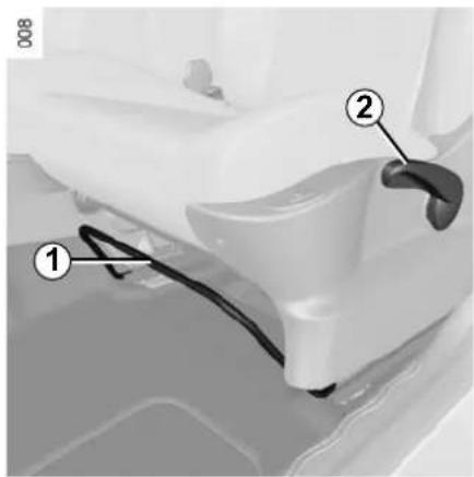
To move forwards or backwards
Lift handle 1 underneath the seat to release. Release the handle once the seat is in the correct position and ensure that the seat is fully locked into position.
To tilt the seatback
Turn control knob 4 and tilt the seat-back to the desired position.

Adjusting the height of the driver's seat
Move lever 2 as many times as necessary:
- upwards to raise it;
- downwards to lower it.
Heated seats
With the ignition switched on, press switch 3 on the required seat. The indicator light in the switch lights up.
The system, which has a thermostat, decides whether or not the heating is needed.


For safety reasons, carry out any adjustments when the vehicle is not being driven.
We would advise you not to recline the seatbacks too far to ensure that the effectiveness of the seat belts is not reduced.
Nothing should be placed on the floor (area in front of driver) as such objects may slide under the pedal during braking manoeuvres, thus obstructing its use.
SEAT BELTS (1/4)
Always wear your seat belt when travelling in your vehicle. You must also comply with the legislation of the particular country you are in.
Before starting, first adjust your driving position, then ask all passengers to adjust their seat belts to ensure optimum protection.

Incorrectly adjusted or twisted seat belts may cause injuries in the event of an accident.
Use one seat belt per person, whether child or adult.
Even pregnant women should wear a seat belt. In this case, ensure that the lap belt is not exerting too much pressure on the abdomen, but do not allow any slack.
Adjusting your driving position
- Sit well back in your seat (having first removed your coat or jacket). This is essential to ensure your back is positioned correctly;
- adjust the distance between the seat and the pedals. Your seat should be as far back as possible while still allowing you to depress the clutch pedal fully. The seatback should be adjusted so that your arms are slightly bent when you hold the steering wheel;
- adjust the position of your headrest. For safety reasons, the top of the headrest must be level with the top of the head;
- adjust the height of the seat. This adjustment allows you to select the seat position which offers you the best possible view;
- adjust the position of the steering wheel.
Refer to the information on the "Steering wheel" in Section 1.

Adjusting the seat belts
Sit with your back firmly against the seatback.
Shoulder strap 1 should be as close as possible to the base of the neck but not on it.
Lap belt 2 should be worn flat over the thighs and against the pelvis.
The belt should be worn so that it is as close as possible to your body, i.e.: avoid wearing heavy clothing or keeping bulky objects under the belts, etc.
SEAT BELTS (2/4)

To fasten
Unwind the belt slowly and smoothly and ensure that buckle 3 locks into catch 5 (check that it is locked by pulling on buckle 3).
If the belt jams before it clicks in, allow it to return before attempting to unwind it again.
If your seat belt is completely jammed, pull slowly, but firmly so that just over 3 cm unwinds. Allow it to return slightly before attempting to unwind it again.
If there is still a problem, contact an approved dealer.

Seat belt reminder warning light
This warning light on the instrument panel or dashboard goes out to let you know that the seat belt has been correctly fastened.
Unlocking
Press button 4 on catch 5 and the seat belt will be rewound by the inertia reel. Guide the buckle to help the operation.
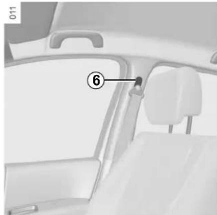
Adjusting the height of the seat belt
Move button 6 to select the position you require so that chest strap 1 is worn as described above.
Make sure that the seat belt is locked in position correctly after you have adjusted it.
SEAT BELTS (3/4)
Rear side seat belts 7
The belts are locked, unlocked and adjusted in the same way as the front belts.

Rear centre belt
Unwind belt 9 slowly from its housing, then fasten buckle 8 into the corresponding black catch 11.

Make sure that the rear bench seats are locked in position properly so that the seat belts will operate efficiently. Refer to the information on the "Rear bench seats" in Section 3.

Fasten sliding buckle 10 into the corresponding red catch 12.

Check that the rear seat belts are positioned and operating correctly each time the rear bench seat is
moved.
SEAT BELTS (4/4)
The following information applies to the vehicle's front and rear seat belts.

- No modification may be made to the component parts of the originally fitted restraint system: belts, seats and their mountings. For special operations (e.g. fitting child seats), contact an authorised dealer.
- Do not use devices which allow any slack in the belts (e.g. clothes pegs, clips, etc.): a seat belt which is worn too loosely may cause injury in the event of an accident.
- Never wear the shoulder strap under your arm or behind your back.
- Never use the same belt for more than one person and never hold a baby or child on your lap with your seat belt around them.
- The belt should never be twisted.
- Following an accident, have the seat belts checked and replaced if necessary. Always replace your seat belts as soon as they show any signs of wear.
- When putting back the rear bench seat, make sure the seat belts are correctly positioned so that they can be used properly.
- Make sure that the buckle is inserted into the appropriate catch.
- Ensure that no objects are placed in the area around the seat belt catch as they could prevent it from being properly secured.
- Make sure the seat belt catch is properly positioned (it should not be hidden away, crushed or flattened by people or objects).
METHODS OF RESTRAINT IN ADDITION TO THE FRONT SEAT BELTS (1/4)
These are:
- pretensioners,
- chest and lap belt force limiters,
- air bags for driver and front passenger.
These systems are designed to operate independently or together in the event of a front, side or rear impact.
Depending on the severity of the impact, the system can trigger:
- seat belt locking;
- the lap belt pretensioner to keep the occupant in their seat, the low volume front air bag and the force limiter; – the large volume air bag.

Pretensioners
With the ignition switched on, if the vehicle is subjected to a significant frontal impact the system may, depending on the severity of impact, trigger piston 1 which instantly retracts the belt.
The pretensioners flatten the belt against the body, holding the occupant against the seat, thus improving the efficiency of the belt.

- Have the entire restraint system checked following an accident.
- No operation whatsoever is permitted on any part of the system (pretensioners, air bags, computers, wiring) and the system components must not be reused on any other vehicle, even if identical.
- To avoid incorrect triggering of the system which may cause injury, only qualified personnel from an approved dealer may work on the pretensioner and air bag system.
- The electric trigger system may only be tested by a specially trained technician using special equipment.
- When the vehicle is scrapped, contact an approved dealer for disposal of the pretensioner and air bag gas generators.
METHODS OF RESTRAINT IN ADDITION TO THE FRONT SEAT BELTS (2/4)
Chest-level and lap belt load limiters
Above a certain severity of impact, this mechanism is used to limit the force of the belt against the body so that it is at an acceptable level.
Air bags for driver and front passenger
Fitted to the driver and passenger side.
The presence of this equipment is indicated by the word "Air bag" on the steering wheel and the dashboard (air bag zone A) and, depending on the vehicle, a label on the lower part of the windscreen.
Each air bag system consists of:
- an air bag and gas generator fitted on the steering wheel for the driver and in the dashboard for the front passenger;
- an electronic unit for system monitoring which controls the gas generator electrical trigger system;
- a single warning light on the instrument panel.
- remote sensors.


The air bag system uses pyrotechnic principles. This explains why, when the air bag inflates, it will gener-
ate heat, produce smoke (this does not mean that a fire is about to start) and make a noise upon detonation. In a situation where an air bag is required, it will inflate immediately and this may cause some minor, superficial grazing to the skin or other problems.
METHODS OF RESTRAINT IN ADDITION TO THE FRONT SEAT BELTS (3/4)
Operation
This system is only operational when the ignition is switched on.
In a severe frontal impact, the air bags inflate rapidly, cushioning the impact of the driver's head and chest against the steering wheel and of the front passenger against the dashboard. The air bags then deflate immediately so that the passengers are not in any way hindered from leaving the vehicle.

Special feature of the front air bag
There are two volumes of operation depending on the severity of the impact:
- low volume air bag, this is the first stage of operation; – large volume air bag, the straps are torn in order to allow the air bag to inflate to a higher volume (in the event of more severe impacts).

Operating faults
Warning light 1 will light up on the instrument panel when the ignition is switched on and then go out after a few seconds.
If it does not light up when the ignition is switched on, or comes on when the engine is running, there is a fault in the system.
Contact your approved Dealer as soon as possible. Your protection will be reduced until this fault is rectified.
METHODS OF RESTRAINT IN ADDITION TO THE FRONT SEAT BELTS (4/4)
All of the warnings below are given so that the air bag is not obstructed in any way when it is inflated and also to prevent the risk of serious injuries caused by items which may be dislodged when the air bag inflates.

Warnings concerning the driver's air bag
- Do not modify the steering wheel or the steering wheel boss.
- Do not cover the steering wheel boss under any circumstances.
- Do not attach any objects (badge, logo, clock, telephone holder, etc.) to the steering wheel boss.
- The steering wheel must not be removed (except by qualified personnel from our Network).
- When driving, do not sit too close to the steering wheel. Sit with your arms slightly bent (see the information on "Adjusting your driving position" in Section 1). This will allow sufficient space for the air bag to deploy correctly and be fully effective.
Warnings concerning the passenger air bag
- Do not attach or glue any objects (badge, logo, clock, telephone holder, etc.) to the dashboard on or near the air bag.
- Do not place anything between the dashboard and the passenger (pet, umbrella, walking stick, parcels, etc.).
- The passenger must not put his or her feet on the dashboard or seat as there is a risk that serious injuries may occur. In general, parts of the body should be kept away from the dashboard (knees, hands, head, etc.).
- The devices in addition to the front passenger seat belt should be reactivated as soon as a child seat is removed, to ensure the protection of the passenger in the event of an impact.
A CHILD SEAT MUST NOT BE FITTED TO THE FRONT PASSENGER SEAT UNLESS THE ADDITIONAL RESTRAINT SYSTEMS, I.E. THE PASSENGER AIR BAG, ARE DEACTIVATED.
(refer to Section 1 "Child safety: deactivating/activating the front passenger air bag")
METHODS OF RESTRAINT IN ADDITION TO THE REAR SEAT BELTS
Force limiter
Above a certain severity of impact, this mechanism is used to limit the force of the belt against the body so that it is at an acceptable level.

– Have the entire restraint system checked following an accident.
- No operation whatsoever is permitted on any part of the system (air bags, electronic control units, wiring) and the system components must not be reused on any other vehicle, even if identical.
- Only qualified personnel from our Network may work on the air bags; otherwise the system may trigger accidentally and cause injury.
SIDE PROTECTION DEVICES
Side air bags
This air bag may be fitted to each of the front seats and is activated at the sides of the seats (door side) to protect the occupants in the event of a severe side impact.
Curtain air bags
These air bags may be fitted along the top of each side of the vehicle and are triggered along the front and rear side windows to protect the passengers in the event of a severe side impact.
Depending on the vehicle, a marking on the windscreen informs you of the presence of additional means of restraint (air bags, pretensioners, etc.) in the passenger compartment.

These air bags operate through slits in the front seatbacks (door side): never insert any objects in slits.

Warnings concerning the side air bag
- Fitting seat covers: seats equipped with an air bag require covers specifically designed for your vehicle. Contact an approved dealer to find out if these covers are available. The use of any covers other than those designed for your vehicle (including those designed for another vehicle) may affect the operation of the air bags and reduce your protection.
- Do not place any accessories, objects or even pets between the seatback, the door and the internal fittings. Do not cover the seatback with any items such as clothes or accessories. This may prevent the air bag from operating correctly or cause injury when the air bag is deployed.
- No work or modification whatsoever may be carried out on the seat or internal fittings, except by qualified personnel from an approved dealer.
- The area between the rear bench seatback and the trim is the area of air bag operation: no objects must be placed here.
ADDITIONAL METHODS OF RESTRAINT
All the warnings below are given so that air bag activation is not obstructed in any way and also to prevent the risk of serious injuries caused by items which may be dislodged when the air bag inflates.

The air bag is designed to complement the action of the seat belt. Both the air bags and seat belts are integral parts of the same protection system. It is therefore essential to wear seat belts at all times. If seat belts are not worn, the occupants are exposed to the risk of serious injury in the event of an accident. It may also increase the risk of minor superficial injuries occurring when the air bag is deployed, although such minor injuries are always possible with air bags.
If the vehicle should overturn or suffer a rear impact, however severe, the pretensioners and air bags are not always triggered. Shocks to the underbody of the vehicle, e.g. from pavements, potholes or stones, can all trigger these systems.
- No work or modification whatsoever may be carried out on any part of the air bag system (air bags, pretensioners, computer, wiring harness, etc.), except by qualified personnel from an approved dealer.
- To ensure that the system is in good working order and to avoid accidental triggering of the system which may cause injury, only qualified Network personnel may work on the air bag system.
- As a safety precaution, have the air bag system checked if your vehicle has been involved in an accident, or is stolen or broken into.
- When selling or lending the vehicle, inform the user of these points and hand over this driver's handbook with the vehicle.
- When scrapping your vehicle, contact your approved dealer for disposal of the gas generator(s).
CHILD SAFETY: General information (1/2)
Carrying children
Children - and adults - must be correctly seated and strapped in for all journeys. The children being carried in your vehicle are your responsibility.
A child is not a miniature adult. Children are at risk of specific injuries as their muscles and bones have not yet finished growing. The seat belt alone would not provide suitable protection. Use an approved child seat and ensure you use it correctly.
Using a child seat
The level of protection offered by the child seat depends on its ability to restrain your child and on its installation. Incorrect installation compromises the protection it offers the child in the event of harsh braking or an impact.
Before purchasing a child seat, check that it complies with the regulations for the country you are in and that it can be fitted in your vehicle. Consult an approved dealer to find out which seats are recommended for your vehicle.
Before fitting a child seat, read the manual and follow its instructions. If you experience any difficulties during installation, contact the manufacturer of the equipment. Keep the instructions with the seat.
For vehicles fitted with a TRIPTIC rear bench seat, configuring it as a 2-seater bench seat with the large section of the seatback folded down prevents the remaining place being used for fitting child seats using the vehicle seat belt, as it is not possible to fasten it (seat belt buckle inaccessible).
Set a good example by always fastening your seat belt and teaching your child:
- to strap themselves in correctly. - to always get in and out of the car at the kerb, away from busy traffic.
Do not use a second-hand child seat or one without an instruction manual.
Check that there are no objects in the vicinity of the child seat which could impede its operation.

Driver's responsibility when parking or stopping the vehicle
Never leave an animal, child or adult who is not self-sufficient alone on your vehicle, even for a short time.
They may pose a risk to themselves or to others by starting the engine, activating equipment such as the electric windows or by locking the doors.
Also, in hot and/or sunny weather, please remember that the temperature inside the passenger compartment increases very quickly.
RISK OF DEATH OR SERIOUS INJURY.
CHILD SAFETY: General information (2/2)

Never leave a child unattended in the vehicle.
Check that your child is always strapped in and that
the belt or safety harness used is correctly set and adjusted. Avoid wearing bulky clothing which could cause the belts to slacken.
Never let your child put their head or arms out of the window.
Check that the child is in the correct position for the entire journey, especially if asleep.

To prevent the doors being opened, use the "Child safety" device (refer to the information on "Opening
and closing the doors" in Section 1).

A collision at 30 mph (50 km/h) is the same as falling a distance of 10 metres.
Transporting a child without
a restraint is the equivalent of allowing him or her to play on a fourth-floor balcony without railings.
Never travel with a child held in your arms. In the event of an accident, you will not be able to keep hold of the child, even if you yourself are wearing a seat belt.
If your vehicle has been involved in a road accident, replace the child seat and have the seat belts and ISOFIX anchorage points checked.
CHILD SAFETY: choosing a child seat

Rear-facing child seats
A baby's head is, proportionally, heavier than that of an adult and its neck is very fragile. Transport the child in this position for as long as possible (until the age of 2 at the very least). It supports both the head and the neck.
Choose a bucket type seat for best side protection and change it as soon as the child's head is higher than the shell.

Forward-facing child seats
The child's head and abdomen need to be protected as a priority. A forward-facing child seat which is firmly attached to the vehicle will reduce the risk of impact to the head. Ensure your child travels in a forward-facing seat with a harness or buckle for as long as their size permits. Choose a bucket type seat for optimum side protection.

Booster cushions
From 15 kg or 4 years, the child can travel using a booster seat, which will enable the seat belt to be adapted to suit his/her size and shape. The booster seat cushion must be fitted with guides to position the seat belt on the child's thighs rather than the stomach. It is recommended that you use a seat-back fitted with a belt strap guide which can be adjusted in terms of height to position the seat belt in the centre of the shoulder. It must never rest on the neck or on the arm.
Choose a bucket type seat for optimum side protection.
CHILD SAFETY: Choosing a child seat mounting
There are two ways of attaching child seats: via the seat belt or using the ISOFIX system.
Attachment via the seat belt
The seat belt must be adjusted to ensure that it is effective in the event of harsh braking or an impact.
Ensure that the strap paths indicated by the child seat manufacturer are respected.
Always check that the seat belt is correctly fastened by pulling it up, then pulling it out fully whilst pressing on the child seat.
Check that the seat is correctly held by moving it from side to side and back to front: the seat should remain firmly fixed.

Triptic rear bench seat
If the rear bench seat is in the two-seater position with the large section of the
seatback folded down, this prevents the remaining seat being used for the installation of a child seat using the vehicle seat belt, as it is not possible to fasten the seat belt (seat belt buckle not accessible).

Do not use the child seat if it may unfasten the seat belt restraining it: the base of the seat must not rest on
the buckle and/or catch of the seat belt.

The seat belt must never be twisted or have tension relieved. Never pass the shoulder strap under the
arm or behind the back.
Check that the seat belt has not been damaged by sharp edges.
If the seat belt does not operate normally, it will not protect the child.
Consult an approved dealer. Do not use this seat until the seat belt has been repaired.

No modifications may be made to the component parts of the restraint system (belts, ISOFIX and seats or mountings) originally fitted.
Attachment with the ISOFIX system
Authorised ISOFIX child seats are approved in accordance with regulation ECE-R44 in one of the three following scenarios:
– ISOFIX universal 3-point forward-facing seat
- ISOFIX semi-universal 2-point seat - specific
For the latter two, check that your child seat can be installed by consulting the list of compatible vehicles.
Attach the child seat with the ISOFIX locks, if these are provided. The ISOFIX system allows quick, easy, safe fitting.
The ISOFIX system consists of 2 rings and, in some cases, a third ring.

Before using an ISOFIX child seat that you purchased for another vehicle, check that its installation is
authorised. Consult the list of vehicles which can be fitted with the seat with the equipment manufacturer.
CHILD SAFETY: Choosing a child seat mounting (continued)

The two rings 1 are located between the seatback and the seat base of the seat and are identified by a marking.
To ensure your child seat can be easily fitted and locked on rings 1, use access guides 2 on the child seat.

The third ring is used to attach the upper belt on some child seats.
Depending on the vehicle, to attach the child seat belt 3:
- open the ring cover 5, - attach the hook 4 to the ring 5 located on the roof rear cross member
and marked by

- close the cover and tighten the belt. Do not change the position of the bench seat (if sliding) after tensioning the belt.

The ISOFIX anchorage points have been exclusively designed for child seats with the ISOFIX
system. Never fit a different type of child seat, seat belt or other objects to these fittings.
Check that nothing is obstructing the anchorage points.
If your vehicle has been involved in a road accident, have the ISOFIX fittings checked and replace your child seat.
CHILD SAFETY: fitting a child seat (1/6)
Some seats are not suitable for fitting child seats. The diagrams on the following pages show you how to attach a child seat.
The types of child seats indicated may not be available. Before using a different child seat, check with the manufacturer that it can be fitted.

Fit the child seat in a rear seat wherever possible.
Check that when installing the child seat in the vehicle
it is not at risk of coming loose from its base.
If you have to remove the headrest, check that it is correctly stored so that it does not come loose under harsh braking or impact.
Always attach the child seat to the vehicle even if it is not in use so that it does not come loose under harsh braking or impact.
In the front seat
The laws concerning children travelling in the front passenger seat differ in every country. Consult the legislation in force and follow the indications on the diagrams on the following pages.
Before fitting a child seat in this seat (if authorised):
– lower the seat belt as far as possible; - move the seat as far back as possible; - gently tilt the seatback away from vertical (approximately 25°); – on equipped vehicles, raise the seat base as far as possible.
Do not change these settings after the child seat is installed.

RISK OF DEATH OR SERIOUS INJURY: before
fitting a rear-facing child seat in this seat, check
that the air bag has been deactivated (refer to the information on "Deactivating the front passenger air bags" in Section 1).
In the rear side seat
Carrycots can only be fitted in the 3-seater position and will take up at least two seats. Position the child with his or her feet nearest the door.
Push the vehicle seat fully forwards to install a rear-facing child seat, then push it back as far as possible without allowing it to make contact with the child seat. For the safety of the child in the forward-facing seat, do not move the seat in front back past the middle of the runner, do not tilt the seatback too far (maximum of 25°) and raise the seat as much as possible.
Always move the (sliding) bench seat back as far as possible. The floor support of the child seat should rest on the floor in accordance with the child seat instructions. A booster cushion may be fitted on the TRIPTIC bench seat, using the ISOFIX locks and the seat belt, in the 2-seater position only.
In rear centre seat
Seat limited to certain booster cushions available from an approved Dealer. Consult the booklet available from an approved Dealer.
CHILD SAFETY: fitting a child seat (2/6)
Installation diagram (sliding bench seats)

= check the status of the front or bag before fitting a child seat allowing a passenger to use the seat.

RISK OF DEATH OR SERIOUS INJURY: before
fitting a rear-facing child seat in the front passen-
ger seat, check that the air bag has been deactivated (refer to the information on "Deactivating the front passenger air bags" at the end of the paragraph).
Child seat attached using the belt
U = seat which allows a seat with "universal" approval to be attached with a belt;
UD = seat which only allows a rear-facing seat with "universal" approval to be fitted;
L = seat which allows certain booster cushions to be fitted. Consult the booklet available from an approved Dealer.

Using a child safety system which is not approved for this vehicle will not correctly protect the baby or child. They risk serious or even fatal injury.
Child seat attached using the ISOFIX fitting

= seat which allows an ISOFIX child seat to be fitted.

= the rear seats are fitted with an anchorage point which allows a forward-facing ISOFIX child seat with universal approval to be fitted. This is located on the roof rear boss member under a cover.
The size of the ISOFIX child seat is indicated by a letter:
- A, B and B1: for forward-facing seats in group 1 (9 to 18 kg);
- C: rear-facing seats in group 1 (9 to 18 kg);
- D and E: shell seat or rear-facing seats in group 0 or 0+ (less than 13 kg);
- F and G: cots in group 0 (less than 10 kg).
CHILD SAFETY: fitting a child seat (3/6)
The table below summarises the information already shown on the diagram on the previous page, to ensure the regulations in force are respected.
| Type of seat | Weight of the child | ISOFIXseat size | Front passenger seat (1) (3) | Rear side seats (7) (8) | Rear centre seat |
| Carrycot fitted across the vehicle group 0 | < 10 kg F – G X | U - IL (4) X | |||
| Rear-facing shell seat group 0 or 0 + and 1 | < 13 kg and 9 to 18 kg | C, D, E U U - IL (2) (5) X | |||
| Forward-facing seat group 1 | 9 to 18 kg A, B, | B1 X | U - IUF - IL (2) (6) | X | |
| Booster seat group 2 and 3 | 15 to 25 kg and 22 to 36 kg | -X | U – IL (2) (6) (8) | L (2) (6) |

(1) RISK OF DEATH OR
SERIOUS INJURY: before
fitting a rear-facing child
seat in the front passen-
ger seat, check that the air bag has been deactivated (refer to the information on "Deactivating the front passenger air bags" at the end of the paragraph).

(2) For vehicles fitted with
the TRIPTIC rear seat, if
the bench seat is in the
2-seater position with the
large section of the seatback folded down, this prevents the remaining seat from being used for the installation of child seats using the vehicle seat belt, as it is not possible to fasten the seat belt (seat belt buckle not accessible).
CHILD SAFETY: fitting a child seat (4/6)
X = Seat not suitable for fitting child seats.
U = Seat which allows a child seat with "Universal" approval to be attached by seat belt; check that it can be fitted.
IUF/IL = On equipped vehicles, seat which allows a child seat with "universal/semi-universal or vehicle specific" approval to be fitted using the ISOFIX system; check that it can be fitted correctly.
L = Seat which allows certain booster cushions to be fitted. Consult the booklet available from an approved Dealer.
(3) Only a rear-facing child seat can be fitted in this seat: position the vehicle seat as far back and raise it as much as possible, and tilt the seatback slightly (approximately 25°). (4) A carrycot can be installed across the vehicle and will take up at least two seats. Position the child with his or her feet nearest the door. (5) Push the vehicle seat fully forwards to install a rear-facing child seat, then push it back as far as possible without allowing it to make contact with the child seat. (6) Forward-facing child seat; position the seatback of the child seat in contact with the seatback of the vehicle seat. Adjust the headrest, or remove it if necessary. Do not push the seat in front of the child more than halfway back on its runners and do not recline the seatback more than 25°. (7) Before fitting a child seat (excluding carrycot) on vehicles fitted with TRIPTIC bench seats, it is recommended that the bench seat is put in the 2-seater position if possible (refer to information on "Rear bench seat functions" in section 3). In the 2 or 3-seater positions, move the bench seat as far back as possible, checking that the floor support of the child seat is resting on the floor in accordance with the child seat instructions. (8) It is not possible to fit a booster cushion using the ISOFIX anchorage points and the seat belt on the rear side seat when the TRIPTIC bench seat is in the 3-seater position.
CHILD SAFETY: fitting a child seat (5/6)
Installation diagram (fixed bench seat)

= check the status of the front or bag before fitting a child seat allowing a passenger to use the seat.

RISK OF DEATH OR SERIOUS INJURY: before
fitting a rear-facing child seat in the front passenger
fitting a rear-facing child seat in the front passenger seat, check that the air bag has been deactivated (refer to the information on "Deactivating the front passenger air bags" at the end of the paragraph).
Child seat attached using the belt
U = seat which allows a seat with "universal" approval to be attached with a belt;
UD = seat which only allows a rear-facing seat with "Universal" approval to be fitted;
L = seat which allows certain booster cushions to be fitted. Consult the booklet available from an approved Dealer.

Using a child safety system which is not approved for this vehicle will not correctly protect the baby or child. They risk serious or even fatal injury.
Child seat attached using the ISOFIX mounting

= seat which allows an ISOFIX child seat to be fitted.

= the rear seats are fitted with an anchorage point which allows a forward facing ISOFIX child seat with universal approval to be fitted. The anchoring ring is located on the roof rear cross member under cover.
The size of the ISOFIX child seat is indicated by a letter:
- A, B and B1: for forward-facing seats in group 1 (9 to 18 kg);
- C: rear-facing seats in group 1 (9 to 18 kg);
- D and E: shell seat or rear-facing seats in group 0 or 0+ (less than 13 kg);
- F and G: cots in group 0 (less than 10 kg).
CHILD SAFETY: fitting a child seat (6/6)
The table below summarizes the information already shown in the diagram on the previous page, to ensure compliance with the regulations in force.
| Type of seat | Weight of the child | ISOFIX seat size | Front passenger seats (1) (2) | Rear side seats | Rear centre seat |
| Carrycot fitted across the vehicle group 0 | < 10 kg F – G | X U - IL (3) X | |||
| Rear-facing shell seat group 0 or 0 + and 1 | up to 18 kg C, | D, E U U - IL (4) X | |||
| Forward-facing seat group 1 | 9 kg to 18 kg A | B, B1 X U - IUF - | IL (5) X | ||
| Booster seat group 2 and 3 | 15 kg to 36 kg | – X U - IL (5) L (5) |
X = seat not suitable for fitting child seats. U = seat allowing a child seat with "Universal" approval to be attached by seat belt; check that it can be fitted correctly. IUF/IL = on equipped vehicles, seat which allows a child seat with "universal, semi-universal or vehicle specific" approval to be fitted using the ISOFIX system; check that it can be fitted correctly. L = seat which allows certain booster cushions to be fitted. Consult the booklet available from an approved Dealer. (2) Only a rear-facing child seat can be fitted to this seat: position the vehicle seat as far back and as high as possible, and tilt the seatback slightly (approximately 25°). (3) A carrycot can be installed across the vehicle and will take up at least two seats. Position the child with his or her feet nearest the door. (4) Push the vehicle seat fully forwards to install a rear-facing child seat, then push it back as far as possible without allowing it to make contact with the child seat. (5) Forward-facing child seat; position the seatback of the child seat in contact with the seatback of the vehicle seat. Adjust the height of the headrest or remove it if necessary; do not push the seat in front of the child more than halfway back on its runners and do not recline the seatback more than 25°.

(1) RISK OF DEATH OR SERIOUS INJURY: before fitting a rear-facing child seat in the front passenger seat, check that the air bag has been deactivated (refer to the information on "Deactivating the front passenger air bags" at the end of the paragraph).
CHILD SAFETY: deactivating/activating the front passenger air bag (1/3)

Deactivating the front passenger air bags (on equipped vehicles)
You must deactivate the devices in addition to the front passenger seat belt before fitting a child seat in the front passenger seat.

To deactivate the air bags: when the vehicle is stationary, push and turn lock 1 to the OFF position.
With the ignition on, you must check
that indicator light 2 is lit on the central display and, depending on the vehicle, that the message "Passenger air bag deactivated" is displayed.
This light remains permanently lit to let you know that you can fit a child seat.

The passenger air bag must only be deactivated or activated with the ignition off.
If it is interfered with when the vehicle is being driven, indicator
lights on. and will come
Switch the ignition off then on again to reset the air bag in accordance with the lock.
CHILD SAFETY: deactivating/activating the front passenger air bag (2/3)


The markings on the dashboard and labels A on each side of the passenger sun visor 3 (example: label shown above) remind you of these instructions.

DANGER
Since operation of the front passenger air bag is not compatible with the position
of a rear-facing child seat, NEVER fit a rear-facing child seat on a front passenger seat with an active front air bag. The child may suffer very serious injuries if the air bag is triggered.
CHILD SAFETY: deactivating/activating the front passenger air bag (3/3)

Activating the front passenger air bags
You should reactivate the air bag as soon as you remove the child seat from the front passenger seat to ensure the protection of the front passenger in the event of an impact.
To reactivate the air bags: switch off the ignition, press and turn lock 1 to the ON position.
With the ignition on, check that warning light 2 is off. The front passenger seat belt additional restraint systems are activated.

Operating faults
It is forbidden to fit a rear-facing child seat to the front passenger seat if the air bag activation/deactivation system is faulty.
Allowing any other passenger to sit in that seat is not recommended.
Contact your approved dealer as soon as possible.

DANGER
Since operation of the front passenger air bag is not compatible with the position of a rear-facing child seat, NEVER fit a rear-facing child seat on a front passenger seat with an active front air bag. The child may suffer very serious injuries if the air bag is triggered.

The passenger air bag must only be deactivated or activated with the ignition off.
If it is interfered with when the vehicle is being driven, indicator
lights on. and will come
Switch the ignition off then on again to reset the air bag in accordance with the lock.
STEERING WHEEL

Steering wheel height adjustment
Pull lever 1 and place the steering wheel in the required position; push the lever to lock the steering wheel in place.
Make sure that the steering wheel is correctly locked.

For safety reasons, only adjust the steering wheel when the vehicle is stationary.
Never leave the steering wheel on full lock when the vehicle is stationary.
Do not drive with a low battery charge. The steering wheel may not operate correctly.
With the engine switched off, or if there is a system fault, it is still possible to turn the steering wheel. The force required will be greater.
A noise may be heard when the steering wheel is moved quickly. This is normal.

Never switch off the ignition when travelling downhill, and avoid doing so in normal driving (assistance provided).
DRIVER'S POSITION, LEFT-HAND DRIVE
DRIVER'S POSITION, LEFT-HAND DRIVE (continued)
The fittings described depend on the vehicle version and country.
1 Side window demister outlet. 2 Side air vent. 3 Stalk for:
– direction indicator lights; - exterior lights; - front fog lights; - rear fog lights.
4 Driver's air bag location, horn, cruise control/speed limiter controls. 5 Stalk for:
- windscreen and rear screen wash/wipe;
- Trip computer information read-out control.
6 Ignition switch. 7 Instrument panel. 8 Passenger air bag location.
9 Side air vent. 10 Side window demister outlet. 11 Glove box. 12 Centre air vent. 13 Heating or air conditioning control. 14 Central door locking switch. 15 Gear lever. 16 Cigar lighter. 17 Handbrake. 18 Cruise control/speed limiter control. 19 Location for a cup holder, ashtray, etc.
20 Location for radio, navigation system, etc. 21 Hazard warning lights switch. 22 - Radio remote control;
- Hands-free telephone integrated control.
23 Steering column height adjustment control. 24 Bonnet release. 25 Fuse box. 26 Controls for:
- parking distance control;
- traction control; – electric headlight beam adjustment.
DRIVER'S POSITION, RIGHT-HAND DRIVE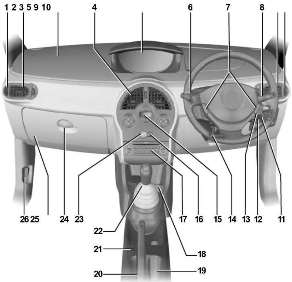
DRIVER'S POSITION, RIGHT-HAND DRIVE (continued)
The fittings described DEPEND ON THE VEHICLE VERSION AND COUNTRY.
1 Side window demister outlet. 2 Side air vent. 3 Location of passenger air bag. 4 Centre air vents. 5 Instrument panel. 6 Stalk for: – direction indicator lights; - exterior lights; - front fog lights; - rear fog lights. 7 Driver's air bag location, horn, cruise control/speed limiter controls. 8 Stalk for: - windscreen and rear screen wash/wipe; - Trip computer information readout control.
9 Side air vent. 10 Side window demister outlet. 11 Controls for: - parking distance control; - traction control; - electric headlight beam adjustment. 12 Ignition switch. 13 - Radio remote control. - Hands-free telephone integrated control. 14 Steering column height adjustment control. 15 Heating or air conditioning control. 16 Central door locking switch.
17 Location for radio, navigation system, etc. 18 Location for a cup holder, ashtray, etc. 19 Cigar lighter. 20 Handbrake. 21 Cruise control/speed limiter control. 22 Gear lever. 23 Hazard warning lights switch. 24 Glove box. 25 Fuse box. 26 Bonnet release.
INSTRUMENT PANEL: warning lights (1/4)
The presence and operation of the warning lights DEPEND ON THE EQUIPMENT AND COUNTRY.

The instrument panel A lights up when the ignition is switched on. In some cases, the appearance of a warning light is accompanied by a message.
The warning light means you should drive very carefully to an approved dealer as soon as possible. If you fail to follow this recommendation, you risk damaging your vehicle.

Left-hand direction indicator tell-tale

Right-hand direction indicator tell-tale

Main beam headlight tell-tale

Dipped beam headlight tell-tale

Front fog light tell-tale

Rear fog light tell-tale

Side light tell-tale light

Door status warning light

Warning light STOP requires you to stop immediately, for your own safety, as traffic conditions allow, turn off the engine and do not restart it. Contact an approved Dealer.

Toxic Fume Filter System Warning Light
For vehicles equipped with this option, the light comes on when the ignition is switched on then goes out.
- If it lights up continuously, consult your approved dealer as soon as possible;
- if it flashes, reduce the engine speed until the light stops flashing. Contact your approved Dealer as soon as possible.
Refer to the information on "Advice: antipollution, fuel economy and driving" in Section 2.

If no lights or sounds are apparent, this indicates a fault in the instrument panel. This indicates that it is essential to stop immediately (as soon as traffic conditions allow). Ensure that the vehicle is correctly immobilised and contact an approved Dealer.
INSTRUMENT PANEL: warning lights (2/4)
The presence and operation of the warning lights DEPEND ON THE EQUIPMENT AND COUNTRY.
STOP light
STOP: This lights up when the ignition is switched on and goes out as soon as the engine is started. It comes on with other warning lights and/or messages, and is accompanied by a beep.
It requires you to stop immediately, for your own safety, as soon as traffic conditions allow. Switch off the engine and do not restart it.
Contact an approved Dealer.

Oil pressure warning light
This lights up when the ignition is switched on and goes out after a few seconds. If it comes on when you are driving, accompanied by the STOP warning light and a beep, it is essential to stop and switch off the ignition.
Check the oil level. If the level is normal, the indicator light is being lit by something else. Contact an approved Dealer.

Battery charge warning light
This lights up when the ignition is switched on and goes out after a few seconds.
If it comes on when you are driving, accompanied by the STOP warning light and a beep, it indicates that the electrical circuit is overcharged or under-charged.
Stop as soon as traffic conditions allow and contact an approved Dealer.

Handbrake on and brake circuit incident warning light
This comes on when the ignition is switched on and goes out as soon as the handbrake is released. If the handbrake is not fully released, the warning light will remain lit, a beep will sound, and the message "handbrake on" will be displayed on the instrument panel when the vehicle reaches a speed of 12 mph (20 km/h) or more.
If it comes on during braking and is accompanied by the STOP warning light and a beep, it indicates that the fluid level in the circuit is low or that there is a braking system fault. Stop as soon as traffic conditions allow and contact an approved Dealer.

Fuel economy indicator lights
This lights up when the ignition is switched on and goes out after a few seconds. This lights up to let you know the best time to engage a higher or lower gear.
INSTRUMENT PANEL: warning lights (3/4)
The presence and operation of the warning lights DEPEND ON THE EQUIPMENT AND COUNTRY.
26620
Anti-lock braking warning light
It comes on when the engine is started then goes out.
If it lights up when you are driving, it indicates a fault in the anti-lock braking system.
Braking will then be as normal, without the ABS. Contact an approved Dealer as soon as possible.

Air bag warning light
This lights up when the ignition is switched on and goes out after a few seconds.
If it does not light up when the ignition is switched on, or comes on when the engine is running, there is a fault in the system. Contact your approved Dealer as soon as possible.

Automatic gearbox operational warning lights

Refer to information on "Automatic gearbox" and "Quickshift gearbox" in Section 2.


Particle filter warning light
Refer to the information on "Special features of diesel versions with particle filter" in Section 2.

Electronic stability program (ESP) and traction control
Warning light
There are several reasons for the warning light to come on: refer to the information on the "Electronic stability program: ESP" and "Traction control: ASR" in Section 2.

Warning light
This lights up when the ignition is switched on and goes out as soon as the engine is started. It can light up in conjunction with other indicator lights and/or messages on the instrument panel.
It means you should drive very carefully to an approved dealer as soon as possible. If you fail to follow this recommendation, you risk damaging your vehicle.

Engine immobiliser system warning light
Refer to the information on the "Engine immobiliser" in Section 1.
INSTRUMENT PANEL: warning lights (4/4)
The presence and operation of the warning lights DEPEND ON THE EQUIPMENT AND COUNTRY.


Speed limiter and cruise control indicator lights
See the information on the "Speed limiter" and "Cruise control" in Section 2.

Driver's seat belt reminder warning light
If the driver's seat belt is not fastened it begins to flash when the vehicle reaches a speed of 12 mph (20 km/h) and a buzzer sounds for approximately two minutes.

Passenger air bag OFF
This warning light comes on several seconds after the ignition is switched on when the front passenger air bags are deactivated (depending on vehicle).

Preheating warning light (diesel version)
This should come on when the ignition is switched on. It indicates that the heater plugs are in operation.
It goes out when preheating is complete. The engine can be started.
INSTRUMENT PANEL: displays and indicators

Coolant temperature indicator 1
In normal use, the needle should be below the area marked 1a. Under severe conditions, the needle may enter this area.
This is not serious unless the STOP warning light comes on, accompanied by a message on the instrument panel and a beep.
Gear engaged indicator 2 (for vehicles with an automatic gearbox).
Rev counter 3
(scale x 1 000)
The red zone indicates a prohibited engine speed
Speedometer 4 (mph or km/h)
Overspeed buzzer
Depending on the vehicle, a buzzer sounds for approximately 10 seconds every 40 seconds, as long as the vehicle is travelling in excess of 72 mph (120 km/h).
Display 5
It lights up to indicate that a door or the tailgate is open or not properly closed (refer to the information on the "Tyre pressure monitor" in Section 2).
Fuel gauge 6
The number of squares lit shows the fuel level.
Minimum fuel level warning 6a
If it flashes and a beep sounds, this indicates that the minimum fuel level has been reached. Fill up with fuel as soon as possible.
Each time the ignition is switched on when the minimum fuel level has been reached, a beep sounds to warn you.
Engine oil level low warning 7
The display informs the driver that the engine oil level is low when the engine is started. This warning lasts for 15 seconds. Refer to the information on the "Engine oil level" in Section 4.
Trip computer and warning system
After 15 seconds, the display switches to the trip computer function. Refer to the information on the "Trip computer and warning system" in the following pages.
INSTRUMENT PANEL: displays and indicators (continued)

Instrument panel brightness adjustment button 7
Refer to the information on "Exterior lighting and signals" in Section 1.
Clock setting button 8
Refer to the information on the "Clock" in Section 1.

Multifunction display 9
This displays several types of information: multimedia information, clock, external temperature.
TRIP COMPUTER: general information (1/2)

Trip computer and warning system 1
Depending on the vehicle, this includes the following functions:
- distance travelled;
- journey parameters;
- information messages;
- operating fault messages (connected to the warning light);
- warning messages (connected to the warning light STOP).
All these functions are described on the following pages.

Display selection keys 2 and 3
Scroll through the following information in this order or reverse the order by briefly pressing the key repeatedly.
a) Total mileage and trip mileage recorder,
b) journey parameters:
- fuel used, – average fuel consumption,
- current fuel consumption (depending on vehicle),
- estimated range,
- distance travelled.
c) mileage before service, d) programmed speed (speed limiter/cruise control), e) on-board log: operating fault and information message readout.
Instrument panel in miles
It is possible to switch to km/h.
With the ignition on, press either button 2 or 3 and turn the key to the accessories position.
The speed measurement unit indicator flashes for approximately three seconds, then the new unit flashes on the display and is then lit up continuously: release button 2 or 3.
To return to the previous mode, repeat the operation.
Note: once the battery is switched off, the trip computer and warning system automatically returns to the original unit of measurement.
TRIP COMPUTER: general information (2/2)

Resetting the trip mileage
With the "trip mileage recorder" selected on the display, press and hold button 2 or 3 until the mileage recorder is reset.
Resetting the journey parameters (reset button)
With one of the trip parameters selected on the display, press button 2 or 3 until the display is reset.
Interpreting some of the values displayed after resetting
The values showing average fuel consumption, range and average speed will become more stable and reliable the further you travel after pressing the reset button.
For the first few miles after pressing the reset button you may notice:
- that the range increases as you travel. This is normal, as average fuel consumption may decrease when:
– the vehicle stops accelerating; - the engine reaches its operating temperature (if the engine was cold when reset button was pressed); - when driving from a built-up area onto the open road.
- You may also notice that the average fuel consumption increases when the vehicle is stationary and the engine idling.
This is normal, since the computer takes account of fuel used during idling.
Automatic resetting of the journey parameters
Resetting occurs automatically when the maximum value of any of the parameters is exceeded.
TRIP COMPUTER AND WARNING SYSTEM: journey parameters (1/4)
The display of information shown below DEPENDS ON THE VEHICLE EQUIPMENT AND COUNTRY.
| Examples of selections Interpreting the display selected | |
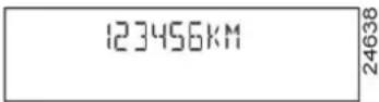 | a) Total mileage recorder |
 | Trip mileage recorder |
 | b) Journey parametersFuel consumed since the last reset. |
 | Average fuel consumption since the last reset.This value is displayed after driving 400 metres and takes into account the distance travelled and the fuel used since the last time the reset button was pressed. |
TRIP COMPUTER AND WARNING SYSTEM: trip parameters (2/4)
The display of information shown below DEPENDS ON THE VEHICLE EQUIPMENT AND COUNTRY.
| Examples of selections Interpreting the display selected | |
CURRENT 12.3L/100 12.3L/100 | Current fuel consumption This value is displayed after a speed of approximately 18 mph (30 km/h) is reached. This value is displayed after a speed of approximately 18 mph (30 km/h) is reached. |
 236.4KM 236.4KM | Estimated range with remaining fuel This range takes into account the average fuel consumption since the last time the reset button was pressed.The value is displayed after driving 400 metres.Several minutes after the reserve light has come on (refer to the information on the “Instrument panel”), the estimated range will no longer be displayed. This range takes into account the average fuel consumption since the last time the reset button was pressed.The value is displayed after driving 400 metres.Several minutes after the reserve light has come on (refer to the information on the “Instrument panel”), the estimated range will no longer be displayed. |
 TRIP275.5KM TRIP275.5KM |  Distance travelled since the last reset. Distance travelled since the last reset. |
 AVERAGE82KM/H AVERAGE82KM/H |  Average speed since the last reset. Average speed since the last reset. |
TRIP COMPUTER AND WARNING SYSTEM: trip parameters (3/4)
The display of information shown below DEPENDS ON THE VEHICLE EQUIPMENT AND COUNTRY.
| Examples of selections Interpreting the display selected | |
 | c) Mileage before serviceDistance remaining until the next service (displayed in miles (kilometres) and months), then when the service nears, several scenarios are possible:- distance/time remaining less than 900 miles (1,500 km) or one month: the message “SERVICE DUE IN” is displayed;- distance equal to 0 miles/km or service date reached: the message “SERVICE DUE” is displayed when the selected display is “mileage before service”, accompanied by the symbol and the warning light.The vehicle requires a service as soon as possible. |
| NB: depending on the vehicle, the mileage before service changes according to the driving style (frequent driving at low speed, door-to-door journeys, extensive use at idle speed, towing a trailer etc.). The distance remaining until the next service can therefore decrease more quickly in some cases than the actual distance travelled.The service intervals are independent of the vehicle’s maintenance schedule: please refer to your vehicle’s Maintenance Service Booklet.Resetting: to reset the distance before service with the display selecting “service”, press and hold one of the display reset buttons for approximately 10 seconds until the display shows the mileage permanently. | |
TRIP COMPUTER AND WARNING SYSTEM: trip parameters (4/4)
The display of information shown below DEPENDS ON THE VEHICLE EQUIPMENT AND COUNTRY.
| Examples of selections Interpreting the display selected | |
 CRUISECONTROL90KM/H CRUISECONTROL90KM/H |  d) Cruise control/speed limiter speed setting (depending on vehicle)Refer to the information on the “Cruise control - Speed limiter” in Section 2. d) Cruise control/speed limiter speed setting (depending on vehicle)Refer to the information on the “Cruise control - Speed limiter” in Section 2. |
| [ TXDI ]SPEED LIMITER90KM/H | |
| AUTO LIGHTS DE-ACTIVATED | [ CWKS ]e) On-board logSuccessive display:– information messages (depending on the vehicle: automatic headlights, etc.),– operating fault messages (check the injection system, etc.). |
TRIP COMPUTER AND WARNING SYSTEM: information messages
These can help in the vehicle starting phase, or give information about a selection or a driving status.
Examples of information messages are given in the following pages.
| Examples of messages Interpreting the display selected | |
| “BOOT OPEN” Indicates that the tailgate has been left open.“OIL LEVEL OK” Indicates that the oil level is correct when the ignition is switched on.“AUTO LIGHTS DE-ACTIVATED” | Indicates that the automatic lights function is deactivated. |
TRIP COMPUTER AND WARNING SYSTEM: operating fault messages
These appear with the warning light and mean that you should drive very carefully to an authorised dealer as soon as possible. If you fail to follow this recommendation, you risk damaging your vehicle.
They disappear when the display selection key is pressed or after several seconds and are stored in the computer log. The warning light stays on. Examples of operating fault messages are given in the following pages.
| Examples of messages Interpreting the display selected | |
| “CHECK ESP SYSTEM” | Indicates a fault in the traction control system (refer to Section 2: “Traction control: ASR”). |
| “CHECK FUEL FILTER” | Indicates that there is water present in the diesel fuel.Contact your approved Dealer as soon as possible. |
| “CHECK GEARBOX” | Indicates that a fault has occurred in the gearbox; contact your approved Dealer as soon as possible. |
| “CHECK AUTO LIGHTS” | Indicates an automatic lights operating fault; contact your approved Dealer. |
| “CHECK STEERING” Indicates a power-assisted steering system operating fault. | |
TRIP COMPUTER AND WARNING SYSTEM : warning messages
These appear with the STOP warning light and require you to stop immediately, for your own safety, as soon as traffic conditions allow. Stop your engine and do not restart it. Contact an approved Dealer.
Examples of warning messages are given in the following pages. Note: the messages appear on the display either individually or alternately (when there are several messages to be displayed), and may be accompanied by a warning light and/or a beep.
| Examples of messages Interpreting the display selected | |
| “INJECTION FAULT” Indicates that the vehicle has a serious engine fault. | |
| “ENGINE OVERHEATING” Indicates that the engine is overheating. | |
| “CHECK STEERING” Indicates a fault in the vehicle’s power-assisted steering. | |
| “GEARBOX OVERHEATING” Indicates that the gearbox is overheating. |
INFORMATION DISPLAYS
Depending on the vehicle, displays 1 or 2 may show:
– the external temperature (zone A); - the radio (zone B); - the time (zone C); – navigation aid information (zone D).

If the electrical supply is cut (battery disconnected, broken supply wire, etc.), the clock will lose its time setting.
The clock must be reset.
We recommend that you do not adjust these settings while driving.
CLOCK

The time is displayed when the ignition is switched on.

Resetting the clock 1
- press button 2 for approximately three seconds to enter time setting mode;
- when the hour flashes, press button 2 again to adjust it;
- wait approximately three seconds, the minutes will flash; press button 2 to set the minutes;
- wait approximately three seconds, the minutes will stop flashing; the time is set.
If the electrical supply is cut (battery disconnected, broken supply wire, etc.), the clock will lose its time setting.
The clock must be reset.
We recommend that you do not adjust these settings while driving.
EXTERNAL TEMPERATURE
External temperature indicator 1
The external temperature is displayed when the ignition is switched on.
Special note:
When the outside temperature is between -3°C and +3°C, the °C characters flash (signalling a risk of black ice on the road).


External temperature indicator
As ice formation is related to exposure, local air humidity and temperature, the external temperature alone is not sufficient to indicate the presence of ice.
DOOR MIRRORS (1/2)

Door mirrors with manual adjustment
To adjust the mirror, move lever 1.

The driver's door mirror may have two clearly defined zones. Zone B shows what can normally be seen
in an ordinary rear view mirror. For your safety, zone A increases the area you can see at the rear and to the side of your vehicle.
The objects in zone A look much further away than they really are.
DOOR MIRRORS (2/2)

Electric door mirrors
With the ignition on, move button 2:
- position C to adjust the left-hand door mirror;
- position E to adjust the right-hand door mirror; D is the inactive position.
Move button 2 to position F and the door mirrors fold in.
To reset them for driving, return to position C, D or E.
Heated door mirrors
With the engine running, mirror de-icing is activated simultaneously with rear screen de-icing/demisting.

The driver's door mirror may have two clearly defined zones. Zone B shows what can normally be seen
in an ordinary rear view mirror. For your safety, zone A increases the area you can see at the rear and to the side of your vehicle.
The objects in zone A look much further away than they really are.

Interior rear view mirror
Its position can be adjusted. When driving at night, to avoid being dazzled by the headlights of the vehicle behind, depress the little lever located behind the rear view mirror 3.
AUDIBLE AND VISUAL SIGNALS

Horn
Press steering wheel boss A.
Headlight flasher
To flash the headlights, even if the lights are not on, pull stalk 1 towards you.

Direction indicators
Move stalk 1 parallel to the steering wheel and in the direction you are going to turn it.
When driving on the motorway, the steering wheel is not often turned enough to return the stalk automatically to 0. There is an intermediate position in which the stalk may be held when changing lanes.
When the stalk is released, it automatically returns to 0.

Hazard warning lights
Press switch 2. This switch ac-
tivates all four direction indicators and the side indicator lights simultaneously. It must only be used in an emergency to warn drivers of other vehicles that you have had to stop in an area where stopping is prohibited or unexpected or that you are obliged to drive under special conditions.
Depending on the vehicle, the hazard warning lights may come on automatically under heavy deceleration. You can switch them off by pressing switch 2.
EXTERIOR LIGHTING AND SIGNALS (1/5)


Switching on the side lights
Turn the end of stalk 1 until the symbol is opposite mark 2.
In all cases, an indicator light on the instrument panel comes on.


Before driving at night, check that the electrical equipment is operating correctly and adjust the headlight beams (if your vehicle is not carrying its normal load). In general, check that the lights are not obscured (by dirt, mud, snow or objects which could cover them).

24434_m
Adjusting the brightness of the instrument panel lighting
With the lights on, press button 3. Each time the button is pressed, the brightness increases; there are four levels of brightness. Pressing the button again will dim the lighting to its lowest level.
EXTERIOR LIGHTING AND SIGNALS (2/5)


Switching on dipped beam headlights
Manual operation
Turn the end of stalk 1 until the symbol is opposite mark 2.
In all cases, an indicator light on the instrument panel comes on.
Automatic operation (depending on vehicle)
With the engine running, the dipped beam headlights are switched on or off automatically depending on the level of ambient light, without the need to operate stalk 1 (position 0).
This function can be deactivated or re-activated.
- To activate it, with the ignition on, press button 4 for at least four seconds. An instrument panel message confirms this action.
- To deactivate it, with the ignition on, press button 4 for at least four seconds. The "Auto lights OFF" message is displayed on the instrument panel.
If stalk 1 is operated, it overrides and cancels the automatic function temporarily.
See-me-home lighting function
This function (useful, for example, for opening a gate, a garage, etc.) enables you to switch on dipped headlights momentarily.
With the ignition off and the headlights off, pull stalk 1 towards you: the dipped beam headlights come on for approximately thirty seconds.
This action may be carried out no more than four times for a maximum lighting period of two minutes.
To switch off the lights before they go out automatically, turn the end of stalk 1, then return it to position 0.
EXTERIOR LIGHTING AND SIGNALS (3/5)
Cornering lights
Depending on the vehicle, if the dipped beam headlights are on when cornering, and under certain driving conditions (speed, steering wheel angle, forwards gear selected, etc.), additional lights are switched on to light the inside of the bend.
Note: under certain conditions of prolonged use, this system will be switched off automatically as it is intended for use over limited periods.


Switching on the main beam headlights
With the dipped beam headlights lit, pull stalk 1 towards you.
When the main beam headlights are lit, an indicator light on the instrument panel comes on.
To return to the dipped headlight position, pull stalk 1 towards you.
Automatic lighting with main beam headlights
Depending on the vehicle, when you change to main beam headlights, the dipped beam headlight raise to improve lighting.
Note: in the event of an operating fault on the system, the dipped beam headlight and the main beam headlight concerned go out and the front fog lights
come on accompanied by the #D instrument panel warning light.
Warning: as this operating mode is not a normal driving condition, consult an approved dealer as soon as possible.
EXTERIOR LIGHTING AND SIGNALS (4/5)

Switching off the lights
Manual operation
There are three options (depending on the vehicle):
– return stalk 1 to its initial position; - the lights extinguish when the engine is stopped, when the driver's door is opened or when the vehicle is locked. In this case, the next time the engine is started the lights will be switched back according to the position of the stalk 1; - a timer will switch off the lights automatically.
Automatic operation (depending on vehicle)
The lights go out when the engine is stopped, when the driver's door is opened or when the vehicle is locked.
Lights-on warning buzzer
If the lights are switched on after the engine is switched off, a warning beep sounds when the driver's door is opened to warn you that the lights are still on.
EXTERIOR LIGHTING AND SIGNALS (5/5)


Front fog lights
Turn centre ring 5 on stalk 1 until the symbol faces mark 6, then release it.
Operation of the fog lights depends on the exterior lighting selected, and an indicator light will light up on the instrument panel.
Do not forget to switch off the fog lights when they are no longer needed, to avoid inconveniencing other road users.
Erratic illumination of the front fog light indicator light on the instrument panel indicates an operating fault with the automatic lighting of the main beam headlights.
Refer to the information on "Automatic lighting with main beam headlights" in Section 1.

Rear fog light
Turn centre ring 5 on stalk 1
until the symbol faces mark 6, then release it.
The fog light can only be switched on if the dipped beam headlights or front fog lights are lit.
To avoid inconveniencing other road users, remember to switch off the rear fog light when it is no longer needed.
Note: the fog light is located on the driver's side.
Switching off the lights
Turn ring 5 again until mark 6 is opposite the symbol for the fog light you wish to switch off.
The front and rear fog lights switch off when the exterior lights are switched off.
When driving in the fog, the dipped beam headlights do not come on automatically, you must switch them on manually.
Switching on the fog lights remains the responsibility of the driver: the indicator lights on the instrument panel inform you whether the fog lights are lit (indicator light on) or not (indicator light not on).
ELECTRIC BEAM HEIGHT ADJUSTMENT

On vehicles fitted with this function, control A allows you to adjust the height of the beams according to the load.
Turn control A downwards to lower the headlights and upwards to raise them.
| Examples of positions for controlA depending on the load | |
| Driver only 0 | |
| Driver with one front passenger | 0 |
| Driver with one front passenger and three rear passengers | 1 |
| Driver with one front passenger, three rear passengers and luggage | 2 |
| Driver with luggage or load reaching the maximum permissible all-up weight | 3 |
WINDSCREEN WASH/WIPE (1/2)

With the ignition on, move stalk 1
A park B intermittent wiping
The wipers will pause for several seconds between sweeps. It is possible to change the time between sweeps by turning ring 2.
C normal wiping speed D fast wiping speed

Special note
When the vehicle is being driven, the wiping speed slows down whenever the vehicle stops. The speed will change from fast wiping speed to normal wiping speed.
As soon as the vehicle moves off, wiping will return to the speed originally selected.
Any action on stalk 1 overrides and cancels automatic operation.

When working in the engine compartment, ensure that the windscreen wiper stalk is in position A (park).
Risk of injury.
Vehicles with automatic wiper function
With the engine running, move stalk 1
A park B automatic wiper function
When this position is selected, the system detects the presence of water on the windscreen and triggers wiping at a suitable wiping speed.
It is possible to modify the sensitivity by turning ring 2.
Each time the engine is started, it is essential to return to park position A then to return to the automatic wiping position.
C normal wiping speed D fast wiping speed
With the vehicle stationary, if for any reason the wipers cannot move (e.g. stuck to windscreen by ice), the system will automatically cut off the power supply to the wipers.
WINDSCREEN WASH/WIPE (2/2)

Windscreen washers, headlight washers (depending on vehicle)
With the ignition on, pull stalk 1 towards you.
Headlights off
A short press triggers one sweep cycle of the wiper.
A longer press triggers three sweeps followed by a final sweep after several seconds.
Headlights on
The headlight washers will be activated at the same time.
In frosty weather, make sure that the wiper blades are not stuck by ice (risk of motor overheating).
Keep an eye on the condition of the blades. Replace the wiper blades as soon as they begin to lose efficiency (approximately once a year).
Clean your windscreen regularly.
If you switch off the ignition before switching off the windscreen wiper (position A), the blades will stop at random on the windscreen.

Before any action on the windscreen (washing the vehicle, de-icing, cleaning the windscreen, etc.), return
stalk 1 to position A (park).
Risk of injury and/or damage.

When working in the engine compartment, ensure that the windscreen wiper stalk is in position A (park).
Risk of injury.
REAR SCREEN WASH/WIPE

24119

Speed-dependent rear screen wiper with
timer
With the ignition on, turn the end of stalk 1 to align mark 2 with the symbol. Wiping frequency varies with speed.

When working in the engine compartment, ensure that the windscreen wiper stalk is in the park position.
Risk of injury.

Rear screen wash/wipe
With the ignition on, turn the
end of stalk 1 to align mark 2 with the symbol.
When the stalk is released, it returns to the rear screen wiper position.
Special note
If the windscreen wipers are operating or are in automatic mode, the rear screen wiper wipes intermittently when reverse gear is engaged.

Before any action on the windscreen (washing the vehicle, de-icing, cleaning the windscreen, etc.) return
stalk 1 to the park position.
Risk of injury or damage.
In freezing or snowy weather, ensure they are not stuck to the windscreen (including the central area located behind the interior rear-view mirror) and the rear screen before starting the wipers (risk of motor overheating).
Check the condition of the wiper blades. You are responsible for their service life:
- they must remain clean: clean the blades, windscreen and rear screen regularly with soapy water;
- do not use them when the windscreen or rear screen are dry;
- free them from the windscreen or rear screen when they have not been used for a long time.
In all cases, replace them as soon as they begin to lose efficiency: approximately once a year.
Before using the rear wiper, check that no object obstructs the travel of the blade.
Do not use the wiper arm to open or close the tailgate.
FUEL TANK (1/2)

Capacity of the fuel tank: approximately 49 litres.
To open compartment A, place your finger into recess 1, then pull the cover.
For details on filling the fuel tank, refer to the information on "Filling with fuel" on the next page.
A cap holder 2 is provided on the fuel filler flap for holding the cap when the tank is being filled.
After filling, check that the cap and cover are closed.


Fuel filler cap: this is of a special type.
If you have to replace it, make sure it is identical
to the original cap. Contact an approved Dealer.
Never place the cap near a source of heat or flame.
Do not wash the filler area with a high-pressure washer.
Fuel grade
Use a high grade fuel that complies with the standards currently in force in each country.
Diesel version
It is essential to use diesel fuel that conforms with the information given on the label inside cover A.
Make sure that no water accidentally enters the fuel tank during filling. The shut-off system and its surrounding area must be dust-free.

Do not mix even small amounts of petrol (unleaded or E85) with diesel.
Do not use ethanol-based fuel; our vehicle is not compatible with this type of fuel.
Do not add any additives to the fuel, as you risk damaging the engine.
FUEL TANK (2/2)
Petrol version
It is essential to use unleaded petrol. The octane rating (RON) must conform with the specifications given on the label inside fuel filler flap A. Refer to the information on "Engine specifications" in Section 6.
Special features of vehicles running on ethanol-based fuel:
It is essential to use unleaded petrol or fuel containing a maximum of 85% ethanol (E85).
To make it easier to start the engine in very cold conditions, it is recommended to use unleaded petrol or, on equipped vehicles, to use the heater integrated in the engine.
In this case, connect the special end of the extension piece supplied into the socket integrated into the radiator grille and the other end into a 220V socket for at least 6 hours before starting.
Note: when using ethanol-based fuel, you may notice over-consumption.
Filling up with fuel
Petrol versions
Using leaded petrol will damage the antipollution system and may lead to a loss of warranty.
To ensure the fuel tank is not filled with leaded petrol, the fuel tank filler neck contains a restrictor fitted with a foolproof system which only allows the nozzle for unleaded petrol to be used (at the pump):
- Insert the nozzle so that the valve is pushed back and fully insert it before beginning to fill the fuel tank, (risk of splash-back);
- Keep the nozzle in this position throughout the entire filling operation.
Petrol and diesel versions
When the pump cuts out automatically at the end of the filling procedure, a maximum of two further filling attempts may be made, as there must be sufficient space in the fuel tank to allow for expansion.

Persistent smell of fuel
If you notice a persistent smell of fuel you should:
- stop the vehicle as soon as traffic conditions allow and switch off the ignition;
- switch on the hazard warning lights and ask your passengers to leave the vehicle and to keep away from traffic;
- contact an approved Dealer.

No modifications whatsoever are permitted on any part of the fuel supply system (computers, wiring,
fuel circuit, injector, protection covers, etc.) as this may be dangerous (such work must be undertaken by qualified Network personnel).
Section 2: Driving
(Advice on use relating to fuel economy and the environment)
Running in 2.2
Ignition switch 2.3
Starting/stopping the engine 2.4
Special features of petrol versions 2.5
Special features of diesel versions 2.6
Special features of diesel versions fitted with a particle filter 2.7
Gear lever/Power-assisted steering 2.8
Handbrake 2.9
Advice on emission control, fuel economy and driving 2.10
Environment 2.13
Anti-lock braking system: ABS. 2.14
Electronic Stability Programme: ESP 2.15
Traction control: ASR. 2.17
Emergency brake assist 2.19
Speed limiter 2.20
Cruise control 2.23
Automatic gearbox 2.27
Quickshift gearbox 2.31
Parking distance control 2.36
2.1
RUNNING IN
Petrol version
For the first 600 miles (1,000 km), do not exceed 78 mph (130 km/h) in the highest gear, or 3,000 to 3,500 rpm.
You may only expect top performance from your vehicle after approximately 1,800 miles (3,000 km).
Service intervals: refer to the Maintenance Service Booklet for your vehicle.
Diesel version
For the first 900 miles (1,500 km), do not exceed 2,500 rpm. After completing this mileage you may drive faster, although you may only expect top performance after approximately 3,600 miles (6,000 km).
During the running in period, do not accelerate hard while the engine is still cold and do not let the engine over-rev.
Service intervals: refer to the Maintenance Service Booklet for your vehicle.
IGNITION SWITCH

Position S: Off and steering lock applied
To lock: remove the key and turn the steering wheel until the steering column locks.
To unlock: turn the key and the steering wheel slightly.
Accessories position A
When the ignition is switched off, any accessories (radio, etc.) will continue to function.
Ignition on position M
The ignition is switched on.
Start position D
If the engine fails to start at the first attempt, the key must be turned back before the starter can be activated again. Release the key as soon as the engine starts.
Note: on diesel versions, several seconds may pass between turning the key and the engine starting to allow for engine preheating.
Starting a vehicle with automatic gearbox
Before starting, move the lever to position N or P.
STARTING/STOPPING THE ENGINE
Starting the engine
Petrol injection
Engine warm or cold
Turn the key to the start position without depressing the accelerator. Release the key as soon as the engine starts.

Diesel injection
Cold or warm engine
Turn the key to "Start" position D without depressing the accelerator. Release the key as soon as the engine starts.
Note: several seconds may pass between turning the key and the engine starting to allow for engine preheating.

When you leave your vehicle, check that the engine has completely stopped.
Stopping the engine
With the engine idling, turn the key back to the Stop position.

Never leave your vehicle with the key inside the vehicle and never leave a child (or a pet) unsupervised, or a short while.
There is a risk that they could start the engine or operate electrical equipment (electric windows etc.) and trap part of their body (neck, arms, hands, etc.).
Risk of serious injury.
Never switch off the ignition before the vehicle has stopped completely. Once the engine has stopped, the brake servo, power-assisted steering, etc. and the passive safety devices such as air bags and pretensioners will no longer operate.
SPECIAL FEATURES OF PETROL VERSIONS
The following operating conditions:
– driving for long periods when the low fuel level warning light is lit; – using leaded petrol; – using fuel or lubrication additives which are not approved.
Or operating faults such as:
- faulty ignition system, running out of fuel or disconnected spark plugs resulting in the engine misfiring or cutting out when driving;
- loss of power,
as they may cause the catalytic converter to overheat and thus reduce its efficiency, or damage it irreparably and cause heat damage to the vehicle.
If you notice any of the above operating faults, have the necessary repairs carried out as soon as possible by an approved Dealer.
These faults may be avoided by regularly taking your vehicle to an approved Dealer at the intervals specified in the Maintenance Service Booklet.
Starting problems
To avoid damaging the catalytic converter, do not keep trying to start the engine (using the start button, or by pushing or towing the vehicle) without having identified and corrected the starting fault.
If the fault cannot be identified, do not keep trying to start the engine, but contact an approved Dealer.

Do not park the vehicle or run the engine in locations where combustible substances or materials such
as grass or leaves can come into contact with the hot exhaust system.
SPECIAL FEATURES OF DIESEL VERSIONS
Diesel engine speed
Diesel engines are fitted with injection equipment which prevents the engine speed being exceeded irrespective of the gear selected.
If the message "Check anti-pollution system" is displayed on the instrument
panel accompanied by the 📄 and warning light; consult an approved dealer straight away.
When driving, depending on the fuel grade used, it is possible that white smoke may be emitted.
This is due to the exhaust particle filter being cleaned automatically, and does not affect the way the vehicle runs.
Running out of fuel
If the tank has been completely drained, the system must be reprimed after the tank is refilled: see information on the "fuel tank" in section 1 before restarting the engine.
Precautions to be taken in winter
To avoid any faults in icy weather:
– ensure that the battery is always fully charged, – always keep the diesel tank relatively full to avoid water vapour condensing in it and accumulating at the bottom of the tank.

Do not park the vehicle or run the engine in locations where combustible substances or materials such as or leaves can come into with the hot exhaust system.
SPECIAL FEATURES OF DIESEL VERSIONS FITTED WITH A PARTICLE FILTER
Depending on the vehicle, the warning light comes on to indicate a filter saturation risk.
Within 60 miles (100 km) of the message appearing, drive at an average speed of 24 mph (40 km/h), as traffic conditions and speed limits allow, until the warning light goes out. If the vehicle is stopped before the message disappears you will have to restart the process from the beginning.
As a guide, this type of cleaning should take up to 20 minutes.
If the message "Check antipollution" is displayed on the instrument panel accompanied by the 📄 and
warning lights; consult an approved dealer straight away.

Do not park the vehicle or run the engine in locations where combustible substances or materials such as leaves can come into contact with the hot exhaust system.
When driving, depending on the fuel grade used, it is possible that white smoke may be emitted.
This is due to the exhaust particle filter being cleaned automatically, and does not affect the way the vehicle runs.
Diesel engine speed
Diesel engines are fitted with injection equipment which prevents the engine speed being exceeded irrespective of the gear selected.
GEAR LEVER/POWER-ASSISTED STEERING

Selecting reverse gear
Vehicles with manual gearbox: refer to the grid on the gear lever knob 1.
Vehicles with an automatic gearbox: refer to the information on the "Automatic gearbox" in Section 2.
The reversing lights will come on as soon as reverse gear is selected with the ignition on.

An impact to the underside of the vehicle (e.g.: striking a post, raised kerb or other street furniture) may result
in damage to the vehicle (e.g.: deformation of an axle).
To avoid any risk of accident, have your vehicle checked by an approved Dealer.
Power Assisted Steering
Never drive with an inadequately charged battery.
Variable power assisted steering
The variable power assisted steering system is equipped with an electronic control system which alters the level of assistance to suit the vehicle speed.
Steering is made easier during parking manoeuvres (for added comfort) whilst the force needed to steer increases progressively as the speed rises (for enhanced safety at high speeds).
Never leave the steering wheel on full lock when the vehicle is stationary.

Never switch off the ignition when travelling downhill, and avoid doing so in normal driving (assistance is not provided).
HANDBRAKE

To release
Pull lever 1 up slightly, press button 2 and then lower the lever to the floor.
The red warning light on the instrument panel will stay on if you are driving with the handbrake not fully released.

Make sure that the hand-brake is properly released when driving (red indicator light off), otherwise over-, or even damage, may
To apply
Pull upwards. Check that the vehicle is immobilised.

When stationary and depending on the slope and/or vehicle load, it may be necessary to pull up the hand at least two extra notches and a gear (1st or reverse gear) classes with a manual gearbox on P for vehicles with an au-gearbox.
ADVICE: antipollution, fuel economy and driving (1/3)
By virtue of its design, moderate fuel consumption and initial settings, your vehicle conforms to current antipollution regulations. The manufacturer is actively striving to reduce pollutant exhaust gas emissions and to save energy. But the fuel consumption of your vehicle and the level of pollutant exhaust gas emissions are also your responsibility. Ensure that it is maintained and used correctly.
Aiding fuel economy
Depending on the vehicle, in order to optimise consumption, the trip computer and warning system will inform you of the best moment to upshift or downshift gears:

upshift a gear;

shift down a gear.
Maintenance
It is important to remember that failure to respect antipollution regulations could lead to legal action being taken against the vehicle owner. In addition, replacing engine, fuel supply system and exhaust components with parts other than those originally recommended by the manufacturer may alter your vehicle so that it no longer complies with antipollution regulations.
Have your vehicle adjusted and checked by an approved dealer, in accordance with the instructions given in your maintenance schedule: they will have all the equipment necessary for ensuring that your vehicle is maintained to its original standard.
Engine adjustments
- ignition: this does not require adjustment.
- spark plugs: for optimum fuel economy, efficiency and performance the specifications laid down by our Design Department must be strictly applied.
If the spark plugs have to be changed, use the make, type and gap specified for your vehicle's engine. Contact an approved dealer for this.
– idling speed: this does not require adjustment. - air filter, diesel filter: a clogged element hinders performance. It must be replaced.
ADVICE: antipollution, fuel economy and driving (2/3)
Exhaust gas monitoring system
The exhaust gas monitoring system will detect any operating faults in the vehicle's antipollution system.
If this system malfunctions, toxic substances may be released into the atmosphere or damage may occur.

This warning light on the instrument panel will indicate if
there are any faults in the system: This lights up when the ignition is switched on and goes out when the engine is started.
- If it lights up continuously, consult an approved Dealer as soon as possible;
- if it flashes, reduce the engine speed until the light stops flashing. Contact your approved dealer as soon as possible.

Driving
- Drive carefully for the first few miles until the engine reaches its normal operating temperature, rather than let it warm up while the vehicle is stationary.
- Speed is expensive.
- Do not overrev the engine in the intermediate gears. Always use the highest gear possible without labouring the engine. On versions with an automatic gearbox, it is preferable to keep the gear lever in position D.
- Avoid sudden acceleration.
- Sporty driving uses a lot of fuel: drive with a light right foot.
- Brake as little as possible. If you anticipate an obstacle or bend in advance, you may then simply release the accelerator pedal.
- Do not try to maintain the same speed up a hill, accelerate no more than you would on the level. Keep your foot in the same position on the accelerator pedal.
- Double declutching and accelerating before switching off are unnecessary in modern vehicles. – Bad weather, flooded roads

Do not drive through floods if the water is above the lower edge of the wheel rims.

Obstructions to the driver On the driver's side, only use mats adapted to the vehicle that attach to the pre-
installed parts, and regularly check their mounting. Do not place several mats on top of each other.
Risk of pedals jamming
ADVICE: antipollution, fuel economy and driving (3/3)

Advice on use
- Electricity is fuel; switch off all the electrical components which are not really needed. However (safety first), keep your lights on when the visibility is bad ("see and be seen").
- Use the air vents. Driving with the windows open at 60 mph (100 km/h) will increase fuel consumption by 4%.
- In vehicles fitted with air conditioning, it is normal to observe an increase in fuel consumption (especially in urban conditions) when it is used. For vehicles fitted with manual air conditioning, switch off the system when it is not required.
Advice for reducing consumption and therefore helping to preserve the environment:
If the vehicle has been parked in the sun, open the doors for a few moments to let the hot air escape before starting the engine.
- Never fill the fuel tank right to the brim to avoid overflow.
- Do not leave an empty roof rack fitted to the vehicle.
- It is better to fit a trailer for bulky objects.
- When towing a caravan, fit a wind deflector and adjust it carefully.

- Avoid using the vehicle for door-to-door calls (short journeys with long waits in between) because the engine never reaches its normal operating temperature.
Tyres
- An under-inflated tyre increases fuel consumption.
- The use of non-recommended tyres can increase fuel consumption.
ENVIRONMENT
Your vehicle has been designed with respect for the environment in mind for its entire service life: during production, use and at the end of its life.
This commitment is illustrated by the eco2 signature of the manufacturer.
Manufacture
Your vehicle has been manufactured at a factory which complies with a policy to reduce the environmental impact on the surrounding areas (reduction of water and energy consumption, visual and noise pollution, atmospheric emissions and waste water; sorting and reusing waste).
Emissions
Your vehicle has been designed to emit fewer greenhouse gases (CO2) while in use, and therefore to consume less fuel (eg. 140 g/km, equivalent to 5.3 l/100 km for a diesel vehicle).
Our vehicles are also equipped with a particle filter system including a catalytic converter, an oxygen sensor and an active carbon filter (the latter prevents vapour from the fuel tank being released into the open air).
For certain diesel vehicles, this system also has a particle filter to reduce the volume of soot particles emitted.
Please make your own contribution towards protecting the environment too.
Worn parts replaced in the course of routine vehicle maintenance (vehicle battery, oil filter, air filter, batteries, etc.) and oil containers (empty or filled with used oil) must be disposed of through specialist organizations.
- At the end of the vehicle's service life, it should be sent to approved centers to ensure that it is recycled. In all cases, comply with local legislation.
Recycling
Your vehicle is 85% recyclable and 95% recoverable.
To achieve these objectives, many of the vehicle components have been designed to enable them to be recycled. The materials and structures have been carefully designed to allow these components to be easily removed and reprocessed by specialist companies.
In order to preserve raw material resources, this vehicle incorporates numerous parts made from recycled plastics or renewable materials (vegetable or animal-derived materials such as cotton or wool).
ANTI-LOCK BRAKING SYSTEM: ABS
Under heavy braking, the ABS prevents the wheels from locking, allowing the stopping distance to be managed and keeping control of the vehicle.
Under these circumstances, the vehicle can be steered to avoid an obstacle whilst braking. In addition, this system can increase stopping distances, particularly on roads with low surface grip (wet ground, etc.).
You will feel a pulsation through the brake pedal each time the system is activated. The ABS does not in any way improve the vehicle's physical performance relating to the road surface and roadholding. It is still essential to follow the rules of good driving practice (such as driving at a safe distance from the vehicle in front).
In an emergency, apply firm and continuous pressure to the brake pedal. There is no need to pump it repeatedly. The ABS will modulate the force applied in the braking system.
Operating faults:
If orange indicator lights (ABS) are displayed on the instrument panel when driving, braking safety is still guaranteed.
If warning lights (ABS), (!), STOP and the message "braking fault" are lit on the instrument panel, this indicates a fault with the braking system and ABS.

Your braking systems are partially operational. However, it is dangerous to brake suddenly and
it is essential to stop immediately, as soon as traffic conditions allow. Contact an approved dealer.
ELECTRONIC STABILITY PROGRAM: ESP (1/2)
This system helps to keep control of the vehicle in critical driving situations (avoiding an obstacle, loss of grip when cornering, etc.) and works in conjunction with the understeer control system.

This function is an additional aid in the event of critical driving conditions, enabling the vehicle behav-
iour to be adapted to suit the driving conditions.
However, the function does not take the place of the driver. It does not increase the vehicle's limits and should not encourage you to drive more quickly.
Therefore, it can under no circumstances replace the vigilance or responsibility of the driver when manoeuvring the vehicle (the driver must always be ready for sudden incidents which may occur when driving).

Operating principle
A sensor in the steering wheel detects the direction selected by the driver.
Other sensors throughout the vehicle measure the actual direction.
The system compares the direction selected by the driver and the actual direction of the vehicle and corrects this as necessary by applying the brakes selectively and/or acting on the engine power.
When the ESP function starts operating, warning light A flashes to warn you.
If the warning light comes on accompanied by the "traction control deselected" message when the engine is started, slowly turn the steering wheel from lock to lock to reinitialise the system.
Understeer control
This system optimises the action of the ESP in the case of pronounced understeering (loss of front axle road holding).
ELECTRONIC STABILITY PROGRAM: ESP (2/2)
Disabling the function
The function is deactivated by pressing switch 1; warning light A will come on to warn you that the system has been deactivated.
This action also deactivates the traction control mechanism: the message "ASR deselected" appears on the instrument panel. Refer to the information on "Traction control: ASR" in the following pages.
Correct this as soon as possible by pressing switch 1 again.
The function is reactivated automatically when the ignition is switched on or when a speed of approximately 30 mph (50 km/h) is exceeded.
It is impossible to deselect this function when travelling above a threshold of approximately 30 mph (50 km/h).


Operating faults
When the system detects an operating fault the message "Check ESP" appears on the instrument panel along with the warning light and warning light A.
Consult your approved Dealer.

Deactivating the ASR function results in the ESP function being deactivated. Refer to the information on
the "Traction control: ASR" on the following pages.
TRACTION CONTROL: ASR (1/2)
This system helps to limit skidding on drive wheels and to control the vehicle when pulling away or accelerating.

This function is an additional aid in the event of critical driving conditions, enabling the vehicle behav-
iour to be adapted to suit the driving conditions.
However, the function does not take the place of the driver. It does not increase the vehicle's limits and should not encourage you to drive more quickly.
Therefore, it can under no circumstances replace the vigilance or responsibility of the driver when manoeuvring the vehicle (the driver must always be ready for sudden incidents which may occur when driving).

Operating principle
Using the wheel sensors, the system measures and compares the speed of the drive wheels at all times and slows down their over-rotation.
If a wheel is starting to slip, the system brakes automatically until the drive supplied becomes compatible with the level of grip under the wheel again.
The system also adjusts the engine speed to the grip available under the wheels, independently of the pressure exerted on the accelerator pedal.
When the function begins to operate, warning light A flashes to warn you.
If the warning light comes on accompanied by the "traction control deselected" message when the engine is started, slowly turn the steering wheel from lock to lock to reinitialise the system.
TRACTION CONTROL: ASR (2/2)
Disabling the function
In some situations (driving on very wet ground: snow, mud, etc. or driving with snow chains fitted), the system may reduce the engine output to limit wheel-spin. If this is not required, it is possible to deactivate the function by pressing switch 1.
The "traction control deselected" message is displayed on the instrument panel along with warning light A to inform you.
Disabling the function also disables the ESP function.
Correct this as soon as possible by pressing switch 1 again.
The function is reactivated automatically when the ignition is switched on or when a speed of approximately 30 mph (50 km/h) is exceeded.
It is impossible to deselect this function when travelling above a threshold of approximately 30 mph (50 km/h).


Disabling the ASR function also disables the ESP function. Refer to the information on the "Electronic sta-
bility program: ESP" in the previous pages.

Operating faults
If the system detects an operating fault, the message "Check ESP" is displayed on the instrument panel display along with the warning light and warning light A.
Consult your approved Dealer.
This system is complementary to the ABS and helps reduce vehicle stopping distances.
Operating principle
The system is for detecting an emergency braking situation. In this case, the braking assistance immediately develops maximum power and may trigger ABS regulation.
ABS braking is maintained as long as the brake pedal is applied.
Hazard warning lights activation
Depending on the vehicle, these may light up in the event of sudden deceleration.

This function is an additional aid in the event of critical driving conditions, enabling the vehicle behav-
iour to be adapted to suit the driving conditions.
However, the function does not take the place of the driver. It does not increase the vehicle's limits and should not encourage you to drive more quickly.
Therefore, it can under no circumstances replace the vigilance or responsibility of the driver when manoeuvring the vehicle (the driver must always be ready for sudden incidents which may occur when driving).
CRUISE CONTROL/SPEED LIMITER: limiter function (1/3)

The speed limiter function helps you stay within the driving speed limit that you choose, known as the limit speed.
This may be useful, for example, driving in urban areas or areas with a speed restriction (roadworks), etc.
The system operates from a driving speed of about 18 mph (30 km/h).

Controls
1 Main "On/Off" switch. 2 Limit speed activation, storage and increase switch (+). 3 Limit speed activation, storage and decrease switch (-). 4 Switch the function to standby (with limit speed memorised (O)). 5 Stored limit speed activation, storage and recall (R).


Indicator light 6
This indicator light on the in-
strument panel lights up to indicate that the limiter function is in operation.
When the function is activated, the message "Limiter" appears on the instrument panel accompanied by dashes.
CRUISE CONTROL/SPEED LIMITER: limiter function (2/3)

Switching on
Press switch 1 on the side showing

The indicator light on the instrument panel will come on.
Limiting the speed
At a steady speed (above 20 mph (30 km/h)), press switch 2 (+): the speed is stored.
The system is designed in such a way that it is possible to detect a difference between the programmed speed and the speed shown on the instrument panel.

Driving
When a limit speed has been stored, if this speed is not reached the vehicle behaves in a similar way to a vehicle without the speed limiter function.
Once you have reached the stored speed, no effort on the accelerator pedal will allow you to exceed the programmed speed except in an emergency (refer to information on "Exceeding the limit speed").
Varying the limit speed
You can vary the limit speed by pressing switch 2 repeatedly to increase the speed or switch 3 (-) to decrease it.
Exceeding the limit speed
In the event of an emergency
It is possible to exceed the limit speed at any moment. To do this: press the accelerator pedal firmly and fully (beyond the kickdown point).
Whilst the speed is being exceeded, the cruising speed displayed on the instrument panel flashes.
When the emergency has passed, release the accelerator pedal: the speed limiter function will return as soon as you reach a speed lower than the limit speed before the emergency.

The speed limiter function is in no way linked to the braking system.
CRUISE CONTROL/SPEED LIMITER: limiter function (3/3)
Limit speed cannot be maintained
In some driving conditions (for example when driving up or down a steep gradient), the system is unable to maintain the limit speed: the stored speed on the instrument panel information display will flash to inform you of this situation.
Putting the function on standby
The speed limiter function is interrupted when you:
- press switch 4 (O);
- engage reverse gear.
In both cases, the speed is memorised and the speed displayed on the instrument panel appears in brackets to confirm the function is on standby.

The speed limiter function is in no way linked to the braking system.

Recalling the limit speed
A stored speed can be recalled by pressing switch 5 (R) until the message "Speed limiter" is displayed.
When the speed limiter is suspended, pressing switches 2 (+) or 3 (-) reactivates the function without taking into account the stored speed: it is the speed at which the vehicle is moving that is taken into account.

Switching off the function
The speed limiter function is interrupted when you press:
- switch 4 (O), in which case the limit speed remains stored and the message "Stored" appears on the instrument panel,
- switch 1, in which case the limit speed is no longer stored, and the indicator light on the instrument panel goes out to confirm that the function has been cancelled.
CRUISE CONTROL/SPEED LIMITER: cruise control function (1/4)

The cruise control function helps you to maintain your driving speed at a speed that you choose, called the cruising speed.
This cruising speed may be set at any speed above 18 mph (30 km/h).

The cruise control function is in no way linked to the braking system.

This function is an additional driving aid. However, the function does not take the place of the driver.
Therefore, it can under no circumstances replace the driver's responsibility to respect speed limits and to be vigilant (the driver must always be ready to brake).
Cruise control must not be used in heavy traffic, on winding or slippery roads (black ice, aquaplaning, gravel) and during bad weather (fog, rain, side winds etc.).
There is a risk of accidents.

Controls
1 Main On/Off switch. 2 Cruising speed activation, storage and increase switch (+). 3 Cruising speed activation, storage and decrease switch (-). 4 Switch the function to standby (with cruising speed memorised (O)). 5 Cruising speed storage and recall switch (R).
CRUISE CONTROL/SPEED LIMITER: cruise control function (2/4)

Switching on
Press switch 1 on the side showing

The corresponding warning light on the instrument panel comes on to indicate that the cruise control function is in operation.
When the function is activated, the message "Cruise control" appears on the instrument panel accompanied by dashes.

Activating cruise control
At a steady speed (above 20 mph (30 km/h)), press switch 2 (+) or 3 (-): the function is activated and the speed is stored.
When the cruise control function is activated, the indicator light on the instrument panel is surrounded by a border.
When activated, the indicator light on the instrument panel is surrounded by a border.
Once a cruising speed is stored and the cruise control function is active, you may lift your foot off the accelerator pedal.
Once a cruising speed is stored and the cruise control function is active, you may lift your foot off the accelerator pedal.

Important: you are nevertheless advised to keep your feet close to the pedals in order to react if necessary.
The system is designed in such a way that it is possible to detect a difference between the programmed speed and the speed shown on the instrument panel.
CRUISE CONTROL/SPEED LIMITER: cruise control function (3/4)

The cruising speed may be changed by pressing repeatedly or continuously on:
The cruising speed may be changed by pressing repeatedly or continuously on:
- switch 3 (-) to decrease the speed.
- switch 3 (-) to decrease the speed.
Exceeding the cruising speed
In the event of an emergency
The cruising speed may be exceeded at any time by depressing the accelerator pedal. While the speed is being exceeded, the cruising speed displayed on the instrument panel flashes.
Then, release the accelerator: the vehicle will automatically return to its set cruising speed.
Unable to maintain the speed selected
In some driving conditions (for example when driving up or down a steep gradient), the system is unable to maintain the set speed: the speed on the instrument panel information display will flash to inform you of this situation.

The cruise control function is in no way linked to the braking system.
CRUISE CONTROL/SPEED LIMITER: cruise control function (4/4)

Putting the function on standby
The function is interrupted when you:
- switch 4 (O),
- depress the brake pedal,
- the clutch pedal or shift into neutral if the vehicle has an automatic gearbox.
In all three cases, the cruising speed remains stored and the message "stored" appears on the instrument panel.
Recalling the cruising speed
If a speed has been stored, it is possible to recall it by pressing switch 5 (R) (the "Cruise control" message appears on the instrument panel) on condition that you are driving faster than 18 mph (30 km/h) and that you are sure that the driving conditions are suitable (traffic, road surface condition, weather conditions, etc.).
Note: if the speed previously stored is much higher than the current speed, the vehicle will accelerate more rapidly to reach this threshold.
When the cruise control is suspended, pressing switches 2 (+) or 3 (-) reactivates the function without taking into account the stored speed: it is the speed at which the vehicle is moving that is taken into account.

Switching off the function
The cruise control function is deactivated if you press switch 1: in this case a speed is no longer stored.
The instrument panel indicator light goes out, confirming that the function is stopped.

Putting the cruise control on standby or switching it off does not cause a rapid reduction in speed: you
must brake by depressing the brake pedal.
AUTOMATIC GEARBOX (1/4)

Selector lever 1
Display A on the instrument panel shows the mode and gear selected.
P: park R: reverse N: neutral D: automatic mode (in forwards gear only) 3: displays gear engaged in manual mode.

Operation
With gear lever 1 in position P or N, switch on the ignition.
To move out of position P, you must depress the brake pedal whilst simultaneously pressing unlocking button 2.
With your foot on the brake pedal (warning light 4 goes out), shift from position P.
Only engage D or R when the vehicle is stopped, with your foot on the brake and the accelerator pedal released.
Driving in automatic mode
Move lever 1 to position D.
In most traffic conditions, you will not have to touch the gear selector lever again: the gears will change automatically at the right time and at the most suitable engine speed because the automatic system takes into account the vehicle load and road contour and adjusts itself to the particular driving style you have chosen.
If the driver's door is open or not properly closed when the gear lever is in position D and the vehicle is moving, a beep sounds.
Economical driving
When driving, leave the lever in position D, keeping the accelerator pedal lightly depressed to ensure automatic gear changes at comparatively low engine speeds.
AUTOMATIC GEARBOX (2/4)
Accelerating and overtaking
Depress the accelerator pedal firmly and fully (so that it goes beyond the kickdown point).
This will enable you to change down to the optimum gear within the engine range.
Driving in manual mode
With selector lever 1 in position D, pull the lever to the left (changing gear using the lever).
Changing gear using the lever
Shifting the lever repeatedly allows you to change gears manually:
- To move down through the gears, push the lever backwards;
- To move up through the gears, push the lever forwards.
The gear selected is displayed on the instrument panel.

Special cases
In certain driving conditions (e.g.: engine protection, operation of the electronic stability program: ESP), the automated system may change the gear automatically.
Likewise, to prevent incorrect manoeuvres, a gear change may be refused by the automatic system: in this case the gear display flashes for a few seconds as a warning.
AUTOMATIC GEARBOX (3/4)

Special circumstances
- Snow position: if you are driving on ground where you are likely to skid (snow, mud, etc.), press switch 4, and operating tell-tale 5 will come on.
Once these special driving conditions no longer apply, exit this function by pressing switch 4 again. Operating tell-tale light 5 goes out.

- If the bends and road surface do not allow you to stay in automatic mode (eg. in the mountains), we recommend that you change to manual mode.
This will prevent the automatic gearbox from changing gear repeatedly when climbing, and permit engine braking on long descents.
- In cold weather, start the engine and wait a few seconds before moving the selector lever from position P or N and engaging it in D or R to prevent the engine stalling.
24491
- Vehicles not fitted with traction control: on a slippery surface or surface with a low level of adhesion, select second gear manually before starting the engine to avoid wheel-spin when starting.
Parking the vehicle
When the vehicle is stopped, move the lever to position P while keeping your foot on the brake pedal: the gearbox is in neutral and the drive wheels are mechanically locked by the driveshaft.
Apply the handbrake.

An impact to the underside of the vehicle while reversing (e.g.: striking a post, raised kerb or other street
furniture) may result in damage to the vehicle (e.g.: deformation of the rear axle).
To avoid any risk of accident, have your vehicle checked by an approved Dealer.
AUTOMATIC GEARBOX (4/4)
Operating faults
- When driving, if the message "Check gearbox" and the warning light appear on the instrument panel, this indicates a fault.
Contact your approved Dealer as soon as possible.
- When driving, if the message "Gearbox overheating" appears on the instrument panel, drive at a moderate speed and avoid leaving the lever in the D (or R) position, where traffic conditions allow: always return to the N position when you stop.
Contact your approved Dealer as soon as possible.
- If a vehicle with an automatic gearbox breaks down, refer to the information on "Towing" in Section 5.
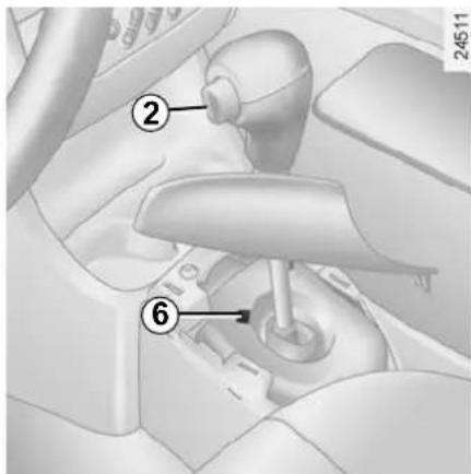
When setting off, if the lever is locked in position P even though you are depressing the brake pedal, the lever can be released manually. To do this, unclip the base of the lever, press recess 6, visible on the gear lever gaiter, and unlocking button 2 on the lever.
QUICKSHIFT GEARBOX (1/5)
Selector lever 1
A/M to change mode (automatic/manual)
▲ to change up a gear ▼ to change down N neutral R reverse

For safety reasons, do not switch off the ignition before the vehicle has come to a complete standstill.

26590
Display
2 automatic mode 3 gear display 4 brake pedal depressed indicator light 5 snow mode
The oil level in the automatic gearbox system reservoir varies depending on use. Adding oil is strictly forbidden (except by qualified approved network personnel).
Switch on the ignition.
The display on the instrument panel switches on.
By default:
- automatic mode is selected (letter A on the display),
- and neutral is engaged (letter N on the display).
Note: if the display does not light up when the ignition is switched on (discharged battery), do not attempt to start the engine by pushing the vehicle.
Starting
The display shows N (neutral) and A (automatic mode).
Moving off forwards
- With your foot on the brake pedal, push the selector lever forwards or backwards and then release it again.
- Release the brake pedal then accelerate gently to move forwards.
Reverse
- With your foot on the brake pedal, push the selector lever towards the right and backwards, and then release it. Reverse gear is engaged (letter R appears on the display).
- Release the brake pedal then accelerate gently to move backwards.
When the vehicle is stationary, push the selector lever towards the front to engage a forwards gear.
Shifting to neutral
With the brake pedal depressed (indicator light 4 will come on if you forget), push the lever towards the right.
Driving in automatic mode
Each time the ignition is switched on, automatic mode is selected by default (letter A on the display).
The vehicle is controlled using the accelerator and the brake.
Gears will change automatically at the correct moment and at a suitable engine speed because automatic mode takes into consideration the road surface and the chosen driving style.
You may change the gear selection made by the automatic system (unless this risks the engine being overrevved or underrevved):
- by pushing the lever forwards or backwards,
- or, depending on the vehicle, by using the paddles (refer to the next page).
QUICKSHIFT GEARBOX (3/5)
Changing mode
You can change mode at any time by pushing the lever to the left. This switches mode without changing gear.
Driving in manual mode
Using the selector lever
Pushing the lever repeatedly allows you to change gears manually.
- to change up a gear: push the lever forwards
- to change down a gear: push the lever backwards
- to change to neutral: with the brake pedal depressed (indicator light 4 will come on if you forget), push the lever towards the right
Note: when the vehicle is stationary (braking, red light, etc.), the system automatically switches to the most suitable gear.
If the engine is being overrevved or underevved, the system will select the optimal gear.
Accelerating and overtaking
To obtain maximum vehicle performance, in automatic or manual mode selected, quickly depress the accelerator pedal beyond the kickdown point.
This will activate the kickdown function allowing you to change down to the most suitable gear.
Parking
To park the vehicle with a gear engaged (on a slope, for example): before switching off the engine, check that a gear other than N is displayed on the instrument panel.
The next time the engine is started, depress the brake pedal. The vehicle will then automatically change to neutral (letter N on the display).
Audible warning
If you leave the vehicle with the engine running when in gear, an audible warning will sound. You must switch to neutral before leaving the vehicle.

Special circumstances
Snow mode
If you are driving on ground where you are likely to skid (snow, mud, etc.), press switch A. Operating tell-tale 5 lights up on the instrument panel.
Once these special driving conditions no longer apply, exit this function by pressing the switch again. The operating tell-tale light goes out.

Selecting snow position activates automatic mode. If you switch to manual mode, it will be deactivated.
Note: snow mode is deselected every time the engine is switched off.
QUICKSHIFT GEARBOX (5/5)
Operating faults
"Check gearbox"
If, when driving, the message "check gearbox" and the warning light appear on the instrument panel, this indicates a fault.
Contact an approved dealer as soon as possible.
"Gearbox overheating"
If you keep the vehicle on a slope for too long without applying the brakes or handbrake, the message "gearbox overheating" will appear along with the warning light.
Depress the brake pedal or apply the handbrake.
The vehicle will not start
If you cannot start the engine and if the battery is not discharged (display lit up):
- switch on the ignition,
- select neutral,
- push the vehicle or roll it down a sufficiently steep slope. Then push the selector lever forwards.
The optimum gear for starting the engine will then be automatically selected.
Note: never attempt this manoeuvre in reverse.
Towing the vehicle
Refer to the information on "Towing: breakdown" in Section 5.
PARKING DISTANCE CONTROL
Operating principle
Ultrasonic sensors, fitted in the vehicle's rear bumper, measure the distance between the vehicle and an obstacle when reversing.
This measurement is indicated by beeps which become more frequent the closer you come to the obstacle, until they become a continuous beep when the vehicle is approximately 30 centimetres from the obstacle.
There is a beep when changing to reverse gear.
Note: make sure that the ultrasonic sensors are not obscured (by dirt, mud, snow, etc.).


This function is an additional aid that indicates the distance between the vehicle and an obstacle whilst reversing, using sound signals.
Under no circumstances should it replace the driver's care or responsibility whilst reversing.
The driver should always pay attention to sudden incidents during driving: always ensure that there are no moving obstacles (such as a child, animal, pram or bicycle, etc.) or small, narrow objects such as stones or posts in your path when manoeuvring.

Temporary deactivation of the system
Press switch 1 to deactivate the system.
The indicator light built into the switch lights up to remind you that the system is deactivated.
Pressing the switch again will reactivate the system and switch off the indicator light.
The system is automatically reactivated after the ignition is switched off and the engine restarted.
PARKING DISTANCE CONTROL (continued)
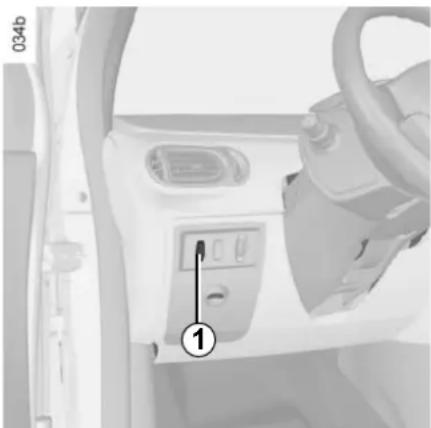
Prolonged deactivation of the system
You can deactivate the system permanently by pressing switch 1 and holding it down for approximately three seconds.
The indicator light built into the switch remains lit constantly.
Once deactivated, the system can be reactivated by pressing the button again for longer than approximately three seconds.
Operating faults
When the system detects an operating fault there will be a 5-second, continuous warning beep when reverse gear is selected. Consult an approved Dealer.

An impact to the underside of the vehicle (e.g.: striking a post, raised kerb or other street furniture) may result
in damage to the vehicle (e.g.: deformation of an axle).
To avoid any risk of accident, have your vehicle checked by an approved Dealer.
Section 3: Your comfort
Air vents. 3.2
Heating and air conditioning 3.4
Electric windows 3.17
Electric sunroof 3.20
Sun visor 3.22
Interior lighting 3.23
Passenger compartment storage space and fittings 3.24
Ashtray – Cigarette lighter 3.29
Fixed rear bench seat 3.30
Sliding rear bench seat 3.32
Triptic rear bench seat. 3.35
Tailgate 3.36
Tailgate rear parcel shelf 3.37
Luggage compartment fittings 3.38
Transporting objects in the boot 3.39
Roof bars 3.40
Bike rack 3.41
3.1
AIR VENTS (air outlets)

1 left-hand side window demister outlet 2 left-hand side air vent 3 windscreen demisting vents 4 centre air vents
5 control panel 6 right-hand side air vent 7 right-hand side window demister outlet 8 passenger footwell heater outlets
AIR VENTS (continued)

Air flow
Move the control knob 1 or 3 (beyond the resistance point).
→: maximum air flow.
: closed.

Direction
Right/left: move tabs 2 or 4.
Up/down: lower or raise tabs 2 or 4.
To remove bad odours from your vehicles, only use the systems designed for this purpose. Consult an approved Dealer.

Do not add anything to the vehicle's ventilation circuit (for example, to remove bad odours).
There is a risk of damage or of fire.
HEATING/AIR CONDITIONING (1/4)

The controls
A Passenger compartment air distribution adjustment. B Air temperature adjustment. C Ventilation speed adjustment. D Air recirculation control.
E Heated rear screen and heated door mirror control and indicator light (depending on vehicle). F Air conditioning operation control and indicator light (depending on vehicle).
Information and advice on use: refer to the end of the information on "Air conditioning".
HEATING/AIR CONDITIONING (2/4)

Distribution of air in the passenger compartment
Move control A to position the pointer opposite the marked positions.

All the air flow is directed to the demisting vents for the windshield and the side windows.
Note: use the air conditioning (depending on the vehicle) to demist the vehicle quickly and position your controls on:
Note: use the air conditioning (depending on the vehicle) to demist the vehicle quickly and position your controls on:
- maximum temperature,
- ventilation speed at 3 or 4,
- demisting.
- The air flow is shared between the side window and windshield demisting vents and the footwells.

The air flow is shared between the side window and wind-demisting vents and the footwells.
This is the recommended position for the best temperature in cold weather.

The air flow is directed mainly towards the passenger footwells.

The air flow is directed mainly towards all the air vents and the passenger footwells.
This is the recommended position for the best temperature in hot weather.

The air flow is directed mainly towards all the air vents.
HEATING/AIR CONDITIONING (3/4)
Adjusting the air temperature
Turn control B to obtain the desired temperature. The further the slide is in the red, the more the temperature will be increased.
Switching air conditioning on or off
The air conditioning is switched on (indicator light illuminated) or off (indicator light extinguished) using button F.
The air conditioning system is used for:
– lowering the temperature inside the passenger compartment; - eliminating condensation.
The air conditioning does not operate when the exterior temperature is low.
B C
F
Adjusting the ventilation speed
Normal use
Turn control C to one of the four positions to start the ventilation system and adjust the power.
Depending on the vehicle, select position 1 or ⚙ for minimum ventilation and position 4 or ⚙ for maximum ventilation.
Position 0
In this position:
- the air conditioning stops automatically even if button F is activated (the indicator light remains lit);
- the ventilation speed of air in the passenger compartment is zero;
- there is, however, a slight flow of air when the vehicle is moving.
This position should not normally be used.
HEATING/AIR CONDITIONING (4/4)

Air recirculation operation (isolation of the passenger compartment)
Turn control D towards the symbol for air recirculation: air is taken from the passenger compartment and is recycled, with no air being taken from outside the vehicle.
Air recirculation is for:
- isolating the vehicle from the external atmosphere (driving in polluted areas, etc.);
- bringing the passenger compartment to the desired temperature as quickly as possible.
Prolonged use of this position can lead to condensation forming on the side windows and windscreen, and problems due to the use of non-renewed air in the passenger compartment.
We therefore advise you to return to normal mode (external air) as soon as the air recirculation function is no longer required, by turning control D again.
Rear screen de-icing/demisting
With the engine running, press button E. The operating tell-tale comes on.
This function permits rapid demisting/de-icing of the rear screen and de-icing of the door mirrors (on equipped vehicles).
To exit this function, press button E again.
Demisting automatically stops.
AUTOMATIC CLIMATE CONTROL

The controls
1 Clear View button to demist and de-ice the windows. 2 Clear View function indicator light. 3 Switching the air conditioning on and off. 4 and 7 Adjusting the air temperature.
5 Display. 6 Starting automatic mode. 8 and 10 Passenger compartment air distribution adjustment. 9 and 11 Ventilation speed adjustment.
12 Heated rear screen and heated door mirrors (depending on vehicle). 13 Heated rear screen warning light. 14 Air recirculation control.
Information and advice for use
Refer to the end of the information on "Heating/air conditioning".
Buttons 1 and 12 are complemented by operation indicator lights (2 and 13):
– indicator light on, the function is switched on, – indicator light off, the function is switched off.
AUTOMATIC CLIMATE CONTROL (continued)

Ambient temperature: automatic mode
Press button 6.
Only the temperature and the AUTO symbol are displayed.
Functions managed in automatic mode are not displayed.
The automatic climate control system guarantees comfort in the passenger compartment and good visibility (except in the event of extreme conditions), while optimising consumption.
This is the recommended mode of use.
- Press button 7 to increase the temperature;
- Press button 4 to decrease the temperature.
Note: The maximum and minimum settings of 15°C and 27°C allow the system to produce a minimum or maximum temperature, whatever the ambient conditions.
In automatic mode (AUTO indicator light on the display is lit), all heating and air conditioning functions are controlled by the system.
When you modify certain functions the AUTO indicator light goes out. Only the modified function is not controlled by the system.
AUTOMATIC CLIMATE CONTROL (continued)
Ambient temperature: automatic mode (continued)
Operation
To reach and keep the chosen comfort level and to maintain good visibility, the system controls:
- ventilation speed;
- air distribution; – air recirculation management; – air conditioning start/stop;
- air temperature.
The displayed temperature values show a comfort level.
When the vehicle is started in cold or hot weather, increasing or decreasing the values displayed does not mean that the temperature level is reached more quickly (the system optimises the temperature increase or decrease whatever the air temperature indicated). The ventilation does not start immediately at maximum power but increases progressively: this may take between a few seconds and several minutes.
Generally speaking, unless there is a particular fault, the dashboard air vents should remain open.
Adjusting automatic mode
The automatic mode is the system's normal operating mode (AUTO light on) but you may alter the selections made by the system (air distribution, etc.).
These options are explained on the following pages.
This is the recommended mode of use: the automatic heating and air conditioning system guarantees comfort (except in the event of extreme conditions) in the passenger compartment and good visibility while optimising consumption.
Return to automatic mode as soon as possible.
AUTOMATIC CLIMATE CONTROL (continued)

Distribution of air in the passenger compartment
There are five possible combinations for air distribution, which may be selected by pressing buttons 8 and 10 repeatedly. The arrows on display 5 indicate the setting selected:
All the air flow is directed to the demisting vents for the windscreen and the side windows.
The air flow is directed to the windscreen and side window demisting vents, and the passenger footwells.
The air flow is directed towards all the air vents.
The air flow is directed towards all the air vents and the passenger footwells.
The air flow is directed mainly towards the passenger foot-well.
The manual air distribution option causes the AUTO (automatic mode) operating tell-tale light on the display 5 to go out, but only air distribution is no longer controlled automatically by the system.
Press button 6 to return to automatic mode.
AUTOMATIC CLIMATE CONTROL (continued)
Varying the ventilation speed
In automatic mode, the system uses the most suitable amount of air to reach and maintain the desired comfort level.
Automatic mode is switched off by pressing buttons 9 and 11.
These buttons allow you to increase or decrease ventilation speed. If you set the ventilation speed to zero, the system switches off.
Switching air conditioning on or off
In automatic mode, the system switches the air conditioning system on or off, depending on the climate conditions.
Exit automatic mode by pressing button 3: the AUTO warning light on display 5 goes out.
Button 3 activates (display warning light comes on) or stops (warning light goes out) the air conditioning function.

Note: the Clear View function automatically activates the air conditioning system (indicator light on). Press button 6 to return to automatic mode.
In automatic mode, in cold weather, the ventilation will not start immediately at maximum power but will increase progressively until the engine temperature is warm enough to heat the passenger compartment air. This may take from a few seconds to several minutes.
AUTOMATIC CLIMATE CONTROL (continued)

Rear screen de-icing/ demisting
With the engine running, press button 12. The operating tell-tale 13 comes on.
This function permits rapid demisting/de-icing of the rear screen and de-icing of the door mirrors (on equipped vehicles).
To exit this function, press button 12 again. Demisting automatically stops by default.
AUTOMATIC CLIMATE CONTROL (continued)

Clear View function
With the engine running, press button 1, and operating tell-tale 2 comes on.
The AUTO button indicator light (on the display) goes out.
This function rapidly demists/de-ices the windscreen, the front side windows and the door mirrors (depending on the vehicle).
It imposes automatic operation of the air conditioning and heating of the rear screen (warning light 13), and inhibits air recirculation.
Press button 12 if you do not want the heated rear screen to be activated. Warning light 13 will go out.
Note: if you wish to reduce the air flow (which may produce a certain amount of noise in the passenger compartment), press button 11.
To exit this function, press either:
- button 1 again,
- button 6 (the AUTO indicator light on the display will light up).
AUTOMATIC CLIMATE CONTROL (continued)

Air recirculation mode
Pressing button 14 activates air recirculation (the symbol lights up on the display).
During recirculation, air is taken from the passenger compartment and is recycled, with no air being taken from outside the vehicle.
Air recirculation allows the external atmosphere to be cut off (when driving in polluted areas, etc.).
Prolonged use of this position may lead to odours, caused by non-renewal of air, and the formation of condensation on the windows.
We therefore advise you to return to normal mode (external air or automatic recirculation) as soon as air recirculation is no longer needed, by pressing button 14.
AIR CONDITIONING: information and advice on use
Fuel consumption
You will normally notice an increase in fuel consumption (especially when driving in town) when the air conditioning is operating. For vehicles fitted with manual air conditioning, switch off the system when it is not required.
Advice for reducing consumption and therefore helping to preserve the environment:
Drive with the air vents open and the windows closed.
If the vehicle has been parked in the sun, open the doors for a few moments to let the hot air escape before starting the engine.
Maintenance
Refer to the Maintenance Service Booklet for your vehicle for the inspection frequency.
Operating faults
As a general rule, contact your approved Dealer in the event of an operating fault.
- Reduction in de-icing, demisting or air conditioning performance. This may be caused by the passenger compartment filter cartridge becoming clogged.
- No cold air is being produced. Check that the controls are set correctly and that the fuses are sound. Otherwise, switch off the system.
Note
Presence of water under the vehicle. After prolonged use of the air conditioning system, it is normal for water to be present under the vehicle. This is caused by condensation.

Do not add anything to the vehicle's ventilation circuit (for example, to remove bad odours).
There is a risk of damage or of fire.

Do not open the refrigerant fluid circuit. The fluid may damage eyes or skin.
ELECTRIC WINDOWS

With the ignition on
Press the switch for the relevant window to lower it to the desired height (the rear windows cannot be lowered completely).
Raise the switch for the relevant window to raise it to the desired height.
Driver's seat
Operate the switches as follows:
- 1 for the driver's side;
- 2 for the front passenger's side;
- 3 and 5 for the rear passenger windows.

Front passenger seat: Press switch 6.

Rear seats: Press switch 7.

Safety of rear occupants
The driver can authorise operation of the rear doors and, depending on the vehicle, the rear electric windows by pressing switch 4. The integrated indicator on the switch confirms this.
Driver's responsibility
Never leave your vehicle with the remote control unit inside and never leave a child (or a pet) unsupervised, even for a short while. The reason for this is that the child may endanger himself or others by starting the vehicle, activating equipment such as the windows, or locking the doors. If something gets trapped, reverse the direction of travel of the window as soon as possible by pressing the relevant switch.
Risk of serious injury.
ONE-TOUCH ELECTRIC WINDOWS (1/2)

The one-touch mode works in addition to the operation of the electric windows described previously.
It is fitted to the driver's window if it is present on the vehicle.
Press switch 1.
The system operates:
– with the ignition on; - with the ignition off until the driver's door is opened/closed (approximately 20 minutes limit).

Driver's responsibility
Never leave your vehicle with the key or remote control inside and never leave a child (or a pet) unsupervised, even for a short while. The reason for this is that the child may endanger himself or others by starting the engine and activating equipment such as the window winders or the sunroof. If any part of the body becomes trapped, reverse the direction of the window immediately by pressing the relevant switch.
Risk of serious injury.
Avoid resting any objects against a half-open window: there is a risk that the electric window could be damaged.

Safety of rear occupants
The driver can inhibit operation of the rear electric windows and doors by pressing on the side with the illustra-

Closing windows can cause serious injury.
ONE-TOUCH ELECTRIC WINDOWS (2/2) MANUAL WINDOW WINDERS
One-touch mode
- Press the switch down fully and briefly: the window will open completely.
- Lift the switch fully and briefly: the window will close completely.
Pressing the switch again while the window is moving will stop its movement.
Special feature
For your safety, your vehicle is fitted with an anti-pinch facility. When a window encounters resistance while closing (for example, someone's fingers, an animal's paw, or a tree branch), it stops and lowers by several centimeters.
Normal mode
- Press down on the relevant switch to lower the window and release it when the window is at the desired height.
- Lift the relevant switch to raise the window and release it when the window is at the desired height.
Operating faults
If a window does not close, the system will change to normal mode: press the relevant switch as often as necessary to close the window, then release it. Press the switch again (still on the closing side) for one second to reset the system.
If necessary, contact your approved Dealer.

Manually operated rear windows: Turn handle 1.
ELECTRIC SUNROOF

The system operates:
- with the ignition on,
- with the ignition off until the driver's door is opened/closed for the first time (approximately 20 minutes limit).
Sun blind
Always operate the sun blind with the sunroof closed:
- to open: push handle 1 upwards and guide the blind as it retracts;
- to close: pull handle 1 until the locks click in place on both sides.

Tilting the sunroof
- to open: open the sun blind then turn button 2 to position A;
- to close: turn button 2 to position 0.
Sliding the sunroof
- to open: open the sun blind then turn button 2 to position B, C or D, depending on the opening position required;
- to close: turn button 2 to position 0.
Never operate the sunroof with the blind closed.
Never drive the vehicle with the sun-roof open and the sun blind closed.

Driver's responsibility
Never leave a child (or animal) alone in the vehicle with the key inside. He/she
may be able to operate the electric sunroof and there is a risk of trapping his/her neck, arm, hand, etc., which could cause serious injuries.
If something gets trapped, reverse the direction of travel as soon as possible by turning button 2 fully to the right (position D).
ELECTRIC SUNROOF (continued)

Special features
If the vehicle is fitted with an anti-pinch facility: when a window encounters resistance whilst closing, (eg.: someone's fingers, an animal's paw or the branch of a tree), it stops and then lowers a few centimetres.
Sunroof closing operating fault
In this case, check that nothing is obstructing it. Turn button 2 to position 0, then press button 3 until the sunroof is completely closed.
Important: during this operation, the sunroof anti-pinch function is deactivated.
Contact your approved Dealer as soon as possible.
Precautions during use
- check that the sunroof is properly closed before leaving your vehicle;
– clean the seal every three months using products recommended by our Technical Department;
- do not open the sunroof immediately after the vehicle has been in the rain or after your car has been washed.
- vehicle with roof bars
It is not advisable to operate the sun-roof.
Before using the sunroof, check the objects and/or accessories (bike racks, roof boxes, etc.) attached to the roof bars: they should be properly arranged and secured and should not interfere with the operation of the sunroof.
Contact your approved Dealer for details of possible conversions.
SUN VISOR

Front sun visor
Lower one of the sun visors 1.
Courtesy mirrors
Slide cover 2.

Child minder mirror 3

Side sun blinds A and B
Pull tab 5 forwards and tab 6 towards the rear of the vehicle until they both click into their respective housings 4 and 7.
INTERIOR LIGHTING

Courtesy light
Press switch 2.
This provides:
- permanent lighting;
- intermittent lighting, which comes on when a door is opened. It only switches off after a time delay and when the doors concerned have been closed correctly; – immediate switching off.
Map reading lights
(depending on vehicle)
Press switch 1 for the driver, 3 for the front passenger.

Driver's and passenger underfloor storage compartment lights 4
(depending on vehicle)
Luggage compartment light
It comes on when the tailgate is opened.
Unlocking and opening the doors or tailgate switches on the timed courtesy lights and lights.
PASSENGER COMPARTMENT STORAGE/FITTINGS (1/5)


Front door storage pockets 1 Driver's and passenger footwell storage compartments 2

Sunglasses holder 3

Ensure that no hard, heavy or pointed objects are placed in the "open" storage compartments in such a
way that they may fall onto passengers during sudden turning, braking or in the event of an accident.

Nothing should be placed on the floor area in front of the driver as such objects may slide under the pedal
during braking manoeuvres, thus obstructing its use.
PASSENGER COMPARTMENT STORAGE/FITTINGS (2/5)

Dashboard storage compartment 4
Depending on the vehicle, it may be fitted with a cover.

Clip 5
This can be used for storing motorway tickets, cards, etc.

Centre console storage compartment 6
This can be used for storing a mobile ashtray, cup holder, etc.

When turning corners, accelerating or braking, ensure that the receptacle being held by the cup is not dislodged.
There is a risk of injury if hot liquid escapes.
PASSENGER COMPARTMENT STORAGE/FITTINGS (3/5)

Passenger seat with integrated object holder 7
To access this location, pull the tab at the rear of the seat base to tilt it forwards.
This location can be used to store a handbag or documents, etc.
There is a strap for holding documents.

For safety reasons, before folding the seat base, check that there is nothing present in the object holder.

Tray under front seat 8
Rear door storage compartment 9

Ensure that no hard, heavy or pointed objects are placed in the "open" storage compartments in such a way that they may fall onto passengers during sudden turning, braking or in the event of an accident.
way that they may fall onto passengers during sudden turning, braking, or in the event of an accident.

This offers support and can be held when the vehicle is being driven. Do not use it for getting into or out of the vehicle.
This offers support and can be held when the vehicle is being driven. Do not use it for getting into or out of the vehicle.
Glove box 11

Pull handle 12 to open it.
Depending on the vehicle, this glove box compartment is ventilated and air conditioned in the same way as the passenger compartment.

Depending on the vehicle, this glove box compartment is ventilated and air conditioned in the same way as the passenger compartment.
Turn blanking cover 13 to open or close the air inlet.
Depending on the vehicle, this socket is located in the passenger glove box.
Depending on the vehicle, this socket is located in the passenger glove box.

Front seat storage compartments 14
PASSENGER COMPARTMENT STORAGE/FITTINGS (5/5)

Rear parcel shelves 15
Raise them to their horizontal position.
It is recommended that you use the shelves only when the vehicle is stationary.

Roof compartments 16
Maximum weight in each compartment: 500 g evenly distributed.
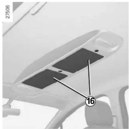

- Always leave the storage compartment covers closed when driving:
– there is a risk of injury when braking suddenly or in the event of an accident;
- there is a risk of objects being hurled through the passenger compartment.
ASHTRAYS - CIGAR LIGHTER

Ashtray 1
This is a removable ashtray which fits into the cup holder in the vehicle.
If your vehicle is not fitted with a cigar lighter and an ashtray, these can be obtained from an approved Dealer.
Cigar lighter 2
With the ignition on, push in cigar lighter 2.
It will spring back with a click when it is ready. Pull it out to use. After use, replace it without pushing it all the way in.

Connect accessories with a maximum power of 120 Watts only.
Fire hazard.
FIXED REAR BENCH SEAT (1/2)

The seat and the seatback may be folded away to allow bulky objects to be carried.
Start by folding down the seat base, then the seatback.

To fold away the seat base
Lift up the front of the seat cushion A until it reaches the stop.
Ensure that both sides of the seat base are unlocked.
Then lift up the rear section of cushion 1 and tilt the seat base so that it is next to the front seats.

To fold down the seatback
Depending on the vehicle, it can be folded down in one or two sections.
Remove the rear headrests if necessary.
Ensure that the front seats are far enough forward.
Place the seat belts in their guides B.
Press button 2 on each side and lower the seatback C.

For safety reasons, carry out any adjustments when the vehicle is not being driven.
FIXED REAR BENCH SEAT (2/2)

To raise the seat base
Proceed in reverse order.
Lower the bench seat cushion A in such a way as to position the rear section of the seat base 1 under the seatback.

Allow the bench seat to turn on its axis naturally without forcing it, guiding it as it lowers onto the floor.

Then push the front 3 of the cushion A in order to lock the seat base.
To raise the seatback
Proceed in reverse order.
Refit the seatback and click it back into place.

When moving the rear seats, ensure that nothing obstructs the anchorage points (passenger's arm or foot, gravel, cloth, toys, etc.).

When refitting the seat-back, make sure it is correctly locked in place. If seat covers are fitted,
make sure these do not prevent the seatback latch from locking in. Make sure that the seat belts are positioned correctly. Reposition the headrests.
SLIDING REAR BENCH SEAT (1/3)

To move forwards or backwards
To unlock the seat:
- from the front, lift one of the levers 1; - from the rear, hold the bars of handle 2 and push them together.
Move the seat forwards or back to the required position.
Release lever 1 or handle 2 and make sure that the seat is locked correctly in position.


For safety reasons, carry out any adjustments when the vehicle is not being driven.
SLIDING REAR BENCH SEAT (2/3)

The seat may be folded down to enable bulky objects to be transported.

To fold down the seatbacks
Special features of the triptic rear bench seat
This must be in the three-seater configuration (refer to the information on "Triptic rear bench seat" in Section 3).
Any sliding rear bench seat
Lower the rear headrests (refer to the information on the "Rear headrests" in Section 1).
Pull lever 3 and lower large seatback B or pull lever 4 and lower small seatback C.


The 2-seater bench seat position with large seat-back B folded down prevents seat position C from
being used, as it is not possible to fasten the seat belt (buckle 5 cannot be accessed).

Check that the rear seat belts are positioned and operating correctly each time the rear seat is moved.

For safety reasons, carry out any adjustments when the vehicle is not being driven.
SLIDING REAR BENCH SEAT (3/3)

To fold down the bench seat Triptic rear bench seat
This should be in the 3-seater position (refer to the next page).
Any sliding rear bench seat Bench seat pushed fully forward with the headrests in the low position:
- fold down the seatbacks;
- lift controls 7 located on each side of the bench seat;
- lift the seat base with handle 2;
- take out the strap from storage compartment 6;
- attach it to one of the front headrest rods and pull it taut.

To reposition the seat
- Lower the bench seat until it locks in position; – fold the seatbacks up again;
- make sure that the seat base and seatbacks lock into position correctly.

When the bench seat has been returned to the position for use, check that it is completely locked into its anchoring points and that no objects can accidentally unlock the controls 7.


The seat belts are not attached to the floor. For your safety, when moving the rear bench seat, check that the sequence of hooks 9 is clean (e.g. gravel, cloth, toys, etc.).
It is essential to check that the seat base hook 8 locks correctly onto the sequence 9.
Check that the rear seat belts are positioned and operating correctly each time the rear bench seat is moved.
TRIPTIC REAR BENCH SEAT
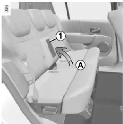
This is a sliding bench seat which, in addition to the settings described in the previous pages, can be configured to two or three seats.
Before moving it, ensure that nobody is occupying the seat or preventing it from being moved.

For safety reasons, carry out any adjustments when the vehicle is not being driven.
For safety reasons, it is not permitted to sit on the centre seat position when section 1 is raised.

Changing to the two-seater configuration
- lift centre section 1 of the bench seat;
- lift handle 2 and push the seat base towards the centre until it locks in place (the second section of the seat is recentred at the same time).
Make sure that the seat base locks into position correctly.
You can then move the bench seat forwards or backwards (four possible positions).
Location A is not a storage compartment.

Changing to the three-seater configuration
- move the bench seat fully forwards,
- lift handle 2 and pull the seat base until the seat locks in place (ensure that the seat base is locked correctly in position);
– lower centre section 1 of the seat.
You can then move the bench seat backwards a notch (two possible positions).
TAILGATE
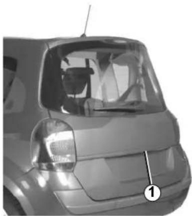
To open
Press button 1 and lift the tailgate.
27429

To close
Lower the tailgate, initially using interior handles 2 to assist you.

Operating faults
If it is not possible to unlock the tailgate, it can be unlocked manually from inside.
- access the luggage compartment by folding forward the seatback(s) of the rear bench seat,
- insert a pencil or similar object in cavity 3 and slide the unit as shown in the illustration,
- Push the tailgate to open it.
TAILGATE REAR PARCEL SHELF
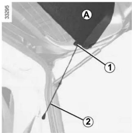
Parcel shelf A
To remove:
- Unhook both straps 2;
- Remove the straps 2 from the guide 1;
- Unclip parcel shelf A.
To refit:
- Clip on the parcel shelf;
- Ensure that the straps feed correctly into the guides 1;
- Hook both straps.

Vehicle with flexible cover B
This is fixed in place with a velcro-type strip. To remove it, detach it from the rear bench seatback.

Vehicle with fixed cover C
Lift the parcel shelf.
To refit it, proceed in reverse order to removal.

Do not place any objects, especially heavy or hard objects, on the parcel shelf.
These may pose a risk to the vehicle occupants if the driver has to brake suddenly or if the vehicle is involved in an accident.
LUGGAGE COMPARTMENT FITTINGS

Location for anchorage points
On equipped vehicles, these are for securing items transported in the luggage compartment (refer to the information on "Transporting objects in the luggage compartment").
Depending on the vehicle, a net for retaining luggage on the floor, located in the storage compartment under the passenger seat, may be attached to these hooks.

Strap
Depending on the vehicle, this strap is used to hold a bottle, etc.

Luggage compartment hook 3
On equipped vehicles, there may be up to three of these in the luggage compartment. These hooks can be used to hold a bag, etc.
TRANSPORTING OBJECTS IN THE LUGGAGE COMPARTMENT
Always position the objects transported so that the largest surface is against:
- The rear bench seatback for normal loads (example A).
- The folded down seat for maximum loads (example B).


If you have to place objects on the folded seatback, with the bench seat in the 3-seater position, remove the front headrests before folding the seatback so that it can be folded as flat as possible against the seat base.

Always position the heaviest items directly on the floor. Use the lashing points on the floor of the luggage
compartment, if these are fitted to the vehicle. The luggage should be loaded in such a way that no items will be thrown forward and strike the occupants if the driver has to brake suddenly. Fasten the rear seat belts, even if the seats are not occupied.
ROOF BARS
084

Access to the mounting points
Open the doors. Behind seal 2 are blanking bolts 1 which protect the mounting bolt locations.

Never remove blanking bolts 1 without plugging the holes afterwards.
When fitting roof bars, replace the blanking bolts with the mounting bolts supplied with the roof bars.

If original roof bars, approved by our Technical Department, are supplied with screws, only use these
screws for attaching the roof bars to the vehicle.
For information on the range of equipment adapted to your vehicle, we advise you to consult an approved Dealer.
Refer to the fitting instructions for information on how to fit roof bars and conditions of use.
Please keep these instructions with the rest of the vehicle documentation.
Maximum permissible load on roof rack: refer to the information on "Weights" in Section 6.
"VELOFIX" BIKE RACK

On vehicles equipped with this accessory, the rear bumper is fitted with two flaps covering the mounting points for the bike rack and an electrical socket 2 located underneath the vehicle.
Each flap is protected by a blanking cover 1.
Accessing the mounting points
Unclip the blanking cover on each side of the rear bumper.
For vehicles not fitted with blanking covers 1, contact your approved Dealer.
Bike rack permissible load: 30 kg.
Refer to the manufacturer's instructions for information on how to fit and use the bike rack.
Please keep these instructions with the rest of the vehicle documentation.
If there is a bike rack light operating fault, contact your approved Dealer as soon as possible.
Section 4: Maintenance
Bonnet 4.2
Engine oil level: 4.4
General information 4.4
Topping up, filling 4.6
Engine oil change 4.7
Levels: engine coolant. 4.8
Brake fluid 4.9
Windscreen/headlight washer reservoir 4.10
Tyre pressure.... 4.11
Battery 4.12
Bodywork maintenance 4.13
Interior trim maintenance.... 4.15
4.1
BONNET (1/2)

To open the bonnet, pull the handle 1.

Unlocking the bonnet catch: To open, push tab 2 to the left as you open the bonnet.

Opening the bonnet: Lift the bonnet and release stay 4 from its holder 5. For your own safety, it is very important to fix the stay into retainer 3 in the bonnet.
Before opening the bonnet, remember to return the windscreen wiper stalk to park position (refer to the information on the "Windscreen wash/wipe" (Section 1).
In the event of even a slight impact involving the radiator grille or bonnet, have the bonnet lock checked by an approved dealer as soon as possible.
The engine may be hot when carrying out operations in close proximity. In addition, the engine cooling fan can come on at any moment. Risk of injury.
BONNET (2/2)

Closing the bonnet
Before closing the bonnet, make sure that nothing has been left in the engine compartment.
To close the bonnet, replace stay 4 in holder 5. Hold the middle of the bonnet and guide it down to one foot (30 cm) above the closed position, then release. It will latch automatically under its own weight.

After carrying out any work in the engine compartment, check that nothing has been left behind (cloth, etc.).
These may damage the engine or cause a fire.

Ensure that the bonnet is properly locked.
Check that nothing is preventing the catch from locking (gravel, cloth, etc.).
ENGINE OIL LEVEL: general information
It is normal for an engine to use oil for lubrication and cooling of moving parts and it is normal to top up the level between oil changes.
However, contact an approved Dealer if more than 0.5 litres is being consumed every 600 miles (1,000 km) after the running in period.
Check the oil level at regular intervals and before any long journey to avoid the risk of damaging your engine.
Reading the oil level
The oil level should be read with the vehicle on level ground, after the engine has been switched off for some time.
The dipstick must be used to read the exact oil level and make sure that the maximum level has not been exceeded (risk of engine damage). Refer to the following pages.
The instrument panel display only alerts the driver when the oil level is at its minimum.

Minimum oil level warning on instrument panel
When the ignition is switched on, if the level is above the minimum level, the display indicates "oil level correct" for approximately 15 seconds: message 1.
To gain a more precise indication, press the information scroll button on the trip computer.
The squares which appear on the display indicate the level. They disappear as the oil level drops and they are replaced by a dash.
To advance to trip computer reading, press the button again.
If the level is at the minimum: the message "Top up oil level" will appear on the display, the squares are replaced by dashes (message 2) and the warning light 📁 on the instrument panel comes on.
It is vital to top up the oil as soon as possible.

The display only warns the driver if the oil level is at the minimum level. It does not inform the driver that the oil
level has exceeded the maximum level as this can only be measured using a dipstick.
ENGINE OIL LEVEL: general information (continued)

Reading the level using the dipstick
- remove the dipstick (refer to the following pages for information on its location);
- wipe the dipstick using a clean, lint-free cloth;
- Push the dipstick in as far as it will go (for vehicles equipped with "cap-type dipstick" C, screw the cap in completely);
- Take out the dipstick again;
- Read the level: it should never fall below minimum mark A or exceed maximum mark B.
Once the level has been checked, ensure that the dipstick is pushed in as far as it will go or that the cap-type dipstick is completely screwed in.
Exceeding the maximum engine oil level
The oil level should only be read with the dipstick as explained above.
If the oil level exceeds the maximum level, do not start your vehicle and contact an approved Dealer.

When working in the engine compartment, ensure that the windscreen wiper stalk is in the park position.
Risk of injury.
Consult your approved Dealer at once if you notice an abnormal or repeated drop in any of the fluid levels.
In order to prevent splashback, it is recommended that a funnel be used when topping up/filling with oil.

Under no circumstances should maximum filling level B be exceeded: this could damage the engine catalytic converter.

The engine may be hot when carrying out operations in close proximity. In addition, the engine cooling fan may come on at any moment. Injury.
ENGINE OIL LEVEL: topping up, filling (1/2)

Topping up/filling
The vehicle must be parked on level ground and the engine should be cold (for instance, before the engine is started up for the first time in the day).
Engine oil grade
Refer to the Maintenance Service Booklet for your vehicle for information regarding which grade of oil to use.
Do not exceed the max level and do not forget to refit cap 1 and dipstick 2.
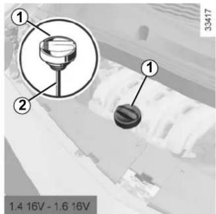
- Unscrew cap 1;
- top up the level (as a guide, the capacity between the minimum and maximum reading on the dipstick 2 is between 1.5 and 2 litres, depending on the engine);
- wait for approximately 10 minutes to allow the oil to flow into the engine;
- check the level using the dipstick 2 (as described above).
Once the operation has been completed, ensure that the dipstick is pushed in as far as it will go or that the cap is completely screwed in.


When working in the engine compartment, ensure that the windscreen wiper stalk is in the park position.
Risk of injury.

The engine may be hot when carrying out operations in close proximity. In addition, the engine cooling
fan can come on at any moment.
Risk of injury.
ENGINE OIL LEVEL: topping up, filling (2/2) / OIL CHANGE
Oil change
Service interval: refer to the Maintenance Service Booklet for your vehicle.
Average capacities for oil changes (oil filter included) (for information)
1.2 16V engine: 4.0 litres; 1.2 16V TCE engine: 4.0 litres; 1.4 16V engine: 4.8 litres; 1.6 16V engine: 4.8 litres; 1.5 dCi engine: 4.5 litres
Engine oil grade
Refer to the Maintenance Service Booklet for your vehicle.
In order to prevent splashback, it is recommended that a funnel be used when topping up/filling with oil.

Filling: take care when topping up the oil that no oil drips onto engine components - risk of fire.
Remember to refit the cap securely as there is a risk of fire if oil splashes onto hot engine components.
Consult your approved Dealer at once if you notice an abnormal or repeated drop in any of the fluid levels.

The engine may be hot when carrying out operations in close proximity. In addition, the engine cooling
fan can come on at any moment.
Risk of injury.

Engine oil change: if you are changing the oil when the engine is hot, be careful not to scald yourself if the oil flows.

Never run the engine in an enclosed space as exhaust gases are poisonous.
LEVELS (1/3)

Coolant
With the engine switched off and on level ground, the level when cold must be between the "MIN" and "MAX" marks on coolant reservoir 1.
Top this level up when cold before the "MIN" mark is reached.
Checking intervals
Check the coolant level regularly (very severe damage is likely to be caused to the engine if it runs out of coolant).
If the level needs to be topped up, only use products approved by our Technical Department which ensure:
– protection against freezing; - anticorrosion protection of the cooling system.

When working in the engine compartment, ensure that the windscreen wiper stalk is in the park position.
Risk of injury.

No operations should be carried out on the cooling circuit when the engine is hot.
Risk of burns.
Replacement intervals
Refer to the Maintenance Service Booklet for your vehicle.
Consult your approved Dealer at once if you notice an abnormal or repeated drop in any of the fluid levels.

The engine may be hot during operations in close proximity. In addition, the engine cooling fan may start at any moment.
Risk of injury.
LEVELS (2/3)

Brake fluid
This should be checked frequently, and immediately if you notice even the slightest loss in braking efficiency.
The level should be read with the engine switched off and on level ground.
Level 2
It is normal for the level to drop as the linings become worn, but it should never drop below the MIN warning line.
Because of the reduced accessibility, we advise you to have the brake fluid level checked and if necessary topped up by a specialist.
If you wish to check the disc and drum wear yourself, you should obtain the document explaining the checking procedure from the manufacturer's network or web site.

When working in the engine compartment, ensure that the windscreen wiper stalk is in the park position.
Risk of injury.
Filling
After any operation on the hydraulic circuit, a specialist must replace the fluid.
Only use fluids approved by the manufacturer's Technical Department (and taken from a sealed container).
Replacement intervals
Refer to the Maintenance Service Booklet for your vehicle.

The engine may be hot during operations in close proximity. In addition, the engine cooling fan may
come on at any moment.
Risk of injury.
LEVELS (3/3) FILTERS

Windscreen/headlight washer reservoir
Filling
With the engine switched off, open cap 3, fill until you can see the fluid, then refit the cap.

When working in the engine compartment, ensure that the windscreen wiper stalk is in the park position.
Risk of injury.

Fluid
Special windscreen washer fluid (product with antifreeze in winter).
Jets
Use a tool such as a needle to adjust the height of the windscreen washer jets.
NOTE
Depending on the vehicle, to find out the fluid level, use the "dropper-cap". To do this, plug hole 4 (in the cap) and remove the cap.
Filters
The replacement of filter elements (air filter, passenger compartment filter, diesel filter, etc.) is scheduled in the maintenance operations for your vehicle.
Replacement intervals for filter elements: refer to the Maintenance Service Booklet for your vehicle.

The engine may be hot during operations in close proximity. In addition, the engine cooling fan may
come on at any moment.
Risk of injury.
TYRE PRESSURE

Label A
Open the driver's door to read it.
Note: the number of lines on the label may vary depending on the vehicle.
Tyre pressures should be checked when the tyres are cold.
If the tyre pressures cannot be checked when the tyres are cold, increase the pressures from 0.2 to 0.3 bar (or 3 PSI). Never deflate a hot tyre.

B: dimension of the tyres fitted to the vehicle. C: tyre pressures for the front wheels (non-motorway driving). D: tyre pressures for the rear wheels (non-motorway).

When they need to be replaced, only tyres of the same make, size, type and profile should be used on a single axle.
Tyres fitted to the vehicle should either be identical to those fitted originally or conform to those recommended by your approved
dealer.
E: tyre pressures for the front wheels (motorway).
F: tyre pressures for the rear wheels (motorway driving).
Special note concerning fully laden vehicles (Maximum Permissible All-Up Weight) and towing a trailer: the maximum speed must be limited to 60 mph (100 kph) and the tyre pressure increased by 0.2 bar.
Please refer to the information on "Weights" in Section 6.
Tyre safety and use of snow chains: please refer to the information on "Tyres" in Section 5 for the servicing conditions and, depending on the version, the use of chains.
BATTERY

The battery 1 does not require any maintenance.

Handle the battery with care as it contains sulphuric acid, which must not come into contact with eyes or skin.
If it does, wash the affected area with plenty of cold water. Consult a doctor if necessary.
Ensure that naked flames, red hot objects and sparks do not come into contact with the battery as there is a risk of explosion.
Replacing the battery
As this operation is complex, we advise you to contact an approved Dealer.

The battery is a specific type, please ensure it is replaced with the same type. Consult an approved
dealer.

Label A
Observe the indications on the battery: - 2 naked flames and smoking forbidden;
- 3 eye protection required;
- 4 keep away from children;
- 5 explosive materials;
- 6 refer to the handbook;
- 7 corrosive materials.

The engine may be hot during operations in close proximity. In addition, the engine cooling fan may
start at any moment.
Risk of injury.
BODYWORK MAINTENANCE (1/2)
A well-maintained vehicle will last longer. It is therefore recommended to maintain the exterior of the vehicle regularly.
Your vehicle has been treated with very effective anti-corrosion products. It is nevertheless subject to various outside influences.
Corrosive agents in the atmosphere
– atmospheric pollution (built-up and industrial areas), – saline atmospheres (near the sea, particularly in hot weather), – seasonal and damp weather conditions (e.g. road salt in winter, water from road cleaners, etc.).
Minor impacts
Abrasive action
Dust and sand in the air, mud, road grit thrown up by other vehicles, etc.
You should take a number of minor precautions in order to safeguard your vehicle against such risks.
What you should not do
Do not degrease or clean mechanical components (e.g. the engine compartment), underneath the body, parts with hinges (e.g. inside the doors) and painted plastic external fittings (e.g. bumpers) using high-pressure cleaning equipment or by spraying on products not approved by our Technical Department. Doing this could give rise to corrosion or operational faults.
Wash the vehicle in bright sunlight or freezing temperatures.
Do not scrape off mud or dirt without pre-wetting.
Allow dirt to accumulate on the exterior.
Allow rust to form following minor impacts.
Do not use solvents not approved by our Technical Department to remove stains as this could damage the paint-work.
Do not drive in snow or muddy conditions without washing the vehicle, particularly under the wheel arches and body.
You should
Wash your car frequently, with the engine off, using cleaning products recommended by the manufacturer (never use abrasive products). Rinse thoroughly beforehand with a jet:
- spots of tree resin and industrial grime;
- mud in the wheel arches and underneath the body, which forms damp patches;
- bird droppings, which cause a chemical reaction with the paint that rapidly discolours paintwork and may even cause the paint to peel off; wash the vehicle immediately to remove these marks since it is impossible to remove them by polishing;
- salt, particularly in the wheel arches and underneath the body after driving in areas where the roads have been gritted.
Remove any plant matter (resin, leaves, etc.) from the vehicle regularly.
BODYWORK MAINTENANCE (2/2)
Respect local regulations about washing vehicles (e.g., do not wash your vehicle on a public highway).
Observe the vehicle stopping distances when driving on gravelled surfaces to prevent paint damage.
Repair, or have repaired quickly, areas where the paint has been damaged, to prevent corrosion spreading.
Remember to visit the body shop periodically in order to maintain your anti-corrosion warranty. Refer to the Maintenance Document.
If it is necessary to clean mechanical components, hinges, etc., spray them with products approved by our Technical Department to protect them after they have been cleaned.
We have selected special products to care for your vehicle and you can obtain these from the manufacturer's accessory outlets.
Vehicles with a matte paint finish
This type of paint requires certain precautions.
Do not do the following
– use wax-based products (polishing); - rub hard; - wash the vehicle in a roller-type car wash; - wash the vehicle using a high-pressure device; - attach stickers to the paintwork (risk of leaving marks).
You should do the following
Wash the vehicle by hand using plenty of water, using a soft cloth or a gentle sponge.
Using a roller type car wash
Return the windscreen wiper stalk to the Park position (refer to the information on the "Windscreen washer, wiper" in Section 1). Check the mounting of external accessories, additional lights and mirrors, and ensure that the wiper blades are secured with adhesive tape. Remove the radio aerial mast if your vehicle is fitted with this equipment. Remember to remove the tape and refit the antenna after washing.
Cleaning the headlights
As the headlights are made of plastic "glass", use a soft cloth or cotton wool to clean them. If this does not clean them properly, moisten the cloth with soapy water, then wipe clean with a soft damp cloth or cotton wool. Finally, carefully dry off with a soft dry cloth.
Cleaning products containing alcohol must not be used.
INTERIOR TRIM MAINTENANCE (1/2)
A well-maintained vehicle will last longer. It is therefore recommended to maintain the interior of the vehicle regularly.
A stain should always be dealt with swiftly.
Whatever type of stain is on the trim, use cold (or warm) soapy water with natural soap.
Detergents (washing-up liquid, powdered products, alcohol-based products) should not be used.
Use a soft cloth.
Rinse and soak up the excess.
Glass instrument panel
(e.g., instrument panel, clock, exterior temperature display, radio display, etc.)
Use a soft cloth (or cotton wool).
If this does not clean it properly, use a soft cloth (or cotton wool) slightly moistened with soapy water and then wipe clean with a soft damp cloth or cotton wool.
Finally, carefully dry off with a soft dry cloth.
Cleaning products containing alcohol must not be used under any circumstances.
Seat belts
These must be kept clean.
Use products selected by our Technical Department (Approved outlets) or warm, soapy water and a sponge and wipe with a dry cloth.
Detergents or dyes must not be used under any circumstances.
Textiles (seats, door trim, etc.)
Vacuum-clean the textiles regularly.
Liquid stain
Use soapy water.
Dab lightly (never rub) with a soft cloth, rinse and remove the excess.
Solid or pasty stain
Carefully remove the excess solid or pasty material immediately with a spatula (working from the edges to the centre to avoid spreading the stain).
Clean as for a liquid stain.
Special instructions for sweets or chewing gum
Put an ice cube on the stain to solidify it, then proceed as for a solid stain.
For further recommendations for maintaining the interior, and/or for any unsatisfactory results, please see an authorised dealer.
INTERIOR TRIM MAINTENANCE (2/2)
Removal/replacing removable equipment originally fitted in the vehicle
If you need to remove equipment in order to clean the passenger compartment (for example, mats), always ensure that they are correctly refitted and are the right way around (the driver's mat should be fitted on the driver's side, etc.) and fit them with the components supplied with the equipment (for example, the driver mat should always be fixed using the pre-fitted mounting components).
With the vehicle stationary, ensure that nothing will impede driving (anything obstructing the pedals, heel wedged by the mat, etc.).
You should not:
You are strongly advised not to position objects such as deodorants, scents, etc. near air vents, as this could damage your dashboard trim.

You are strongly recommended not to use high-pressure or spray cleaning equipment inside the passenger compartment: use of such equipment could impair the correct functioning of the electrical or electronic components in the vehicle, or have other detrimental effects.
You are strongly recommended not to use high-pressure or spray cleaning equipment inside the passenger compartment: use of such equipment could impair the correct functioning of the electrical or electronic components in the vehicle, or have other detrimental effects.
Section 5: Practical advice
Puncture 5.2
Emergency spare wheel 5.2
Tyre inflation kit 5.6
Tool kit (jack, wheelbrace, etc.) 5.9
Wheel trims – Wheel 5.10
Changing a wheel 5.11
Tyres (tyre and wheel safety, use in winter) 5.13
Halogen headlights: changing bulbs 5.16
Rear lights (changing bulbs) 5.19
Indicator lights (changing bulbs) 5.20
Interior lighting (changing bulbs) 5.21
Fuses.... 5.23
Battery 5.25
Radio frequency remote control unit: battery. 5.28
Fitted audio equipment 5.29
Accessories 5.30
Wipers (replacing blades) 5.31
Towing 5.32
Operating faults 5.35
5.1
PUNCTURE, EMERGENCY SPARE WHEEL (1/4)
In the event of a puncture, depending on the vehicle, you will have:
An emergency spare wheel or tyre inflation kit (refer to the information on the following pages).

If the emergency spare wheel has been stored for several years, have it checked by your Dealer to ensure that it is safe to use.
Vehicles fitted with an emergency spare wheel smaller than the four other wheels:
- Never fit more than one emergency spare wheel to the same vehicle.
- Replace the emergency spare wheel as soon as possible with a wheel with the same dimensions as the original.
- When this is fitted to the vehicle, which must only be a temporary measure, the driving speed must not exceed the speed indicated on the label on the wheel.
- Fitting an emergency spare wheel may alter the way the vehicle usually runs. Avoid sudden acceleration or deceleration and reduce your speed when cornering.
- If you need to use snow chains, fit the emergency spare wheel to the rear axle and check the tyre pressure.
PUNCTURE, EMERGENCY SPARE WHEEL (2/4)

The emergency spare wheel is located underneath the vehicle.
- Open the tailgate;
- Lift carpet 1 and place it against the back of the rear bench seat;
- Lift cover 2, then remove it;
- Take out the tool kit, lifting it by both handles 3.
Label A reminds you of how to operate the emergency spare wheel winch.

Unscrew nut 4 in an anti-clockwise direction until it comes off completely, then place the palm of your hand on section B of handle 5 and push towards the front of the vehicle. The wheel will be lowered.

When you push handle 5, the wheel will drop under the vehicle; risk of injury.
Ensure that everybody is kept away from the underside of the vehicle.

Pull the wheel towards you, lay the wheel down flat and unfasten cable 6 from its housing 7; – depending on the vehicle, remove shim 8.
You may remove the wheel from its support.

Do not touch the exhaust as it could burn.
PUNCTURE, EMERGENCY SPARE WHEEL (3/4)

To refit a wheel
To carry out this operation, the cable must be unwound.
If the cable has been wound back up on its own, unwind it again as follows:
– Pull the handle to unwind the cable, - press the button located under handle 5 to hold the unwound cable, then guide it down; – recover the cable from underneath the vehicle; - attach the cable end piece to the wheel support.
You may refit the wheel.

After changing a wheel, position the replaced wheel on support 9, with the valve facing the ground. Depending on the vehicle, reposition shim 8. Clip cable 6 into housing 7, then push the wheel underneath the luggage compartment (tab 10 towards the rear of the vehicle).

Make sure that no one has their fingers close to the cable when you move the handle. Risk of injury.

Position yourself behind the vehicle and pull handle 5 to raise the wheel until it is anchored under the vehicle.
PUNCTURE, EMERGENCY SPARE WHEEL (4/4)

To lock the system:
- press nut 4, screwing it on fully until it locks in place. Several turns will be necessary. This operation is essential to ensure that the wheel is secure; – return handle 5 to its original position;
- clip on the tool kit;
- replace the cover then lower it and replace the luggage compartment carpet.
Note: if the tool kit does not lock in place, check the tightness of nut 4 and the correct positioning of handle 5.
Special features
The emergency spare wheel holder should always be present when you are driving even when the wheel itself is not present: risk of water entering the vehicle.
If you have to release it when it is not holding a wheel, push the centre of the wheel holder towards the ground while pressing handle 4.

It is essential to lock the nut so that the wheel is held securely.

As the punctured wheel is wider than the emergency spare wheel, when you place the punctured wheel in the emergency spare wheel bay, the vehicle's ground clearance is reduced. To prevent damage, proceed carefully when driving over raised sections of road and when dismounting pavements. When this is fitted to the vehicle, which must only be a temporary measure, the driving speed must not exceed the speed indicated on the label on the wheel. Replace the emergency spare wheel as soon as possible with a wheel with the same dimensions as the original.

The system should only be used with the original vehicle wheels.
TYRE PRESSURE KIT (1/3)
32788


The kit repairs tyres when tread A has been damaged by objects smaller than 4 mm. It cannot repair
all types of puncture, such as cuts larger than 4 mm, or cuts in tyre sidewall B.
Ensure also that the wheel rim is in good condition.
Do not pull out the foreign body causing the puncture if it is still in the tyre.

Do not attempt to use the inflation kit if the tyre has been damaged as a result of driving with a puncture.
You should therefore carefully check the condition of the tyre sidewalls before any operation.
Driving with underinflated, flat or punctured tyres can be dangerous and may make the tyre impossible to repair.
This repair is temporary
A tyre which has been punctured should always be inspected (and repaired, where possible) as soon as possible by a specialist.
When taking a tyre which has been repaired using this kit to be replaced, you must inform the specialist.
When driving, vibration may be felt due to the presence of the repair product injected into the tyre.

The kit is only approved for inflating the tyres of the vehicle originally equipped with the kit.
It must never be used to inflate the tyres of another vehicle, or any other inflatable object (rubber ring, rubber boat, etc.).
Avoid spillage on skin when handling the repair liquid bottle. If droplets do leak out, rinse them off with plenty of water.
Keep the repair kit away from children.
Do not dispose of the empty bottle in the countryside. Return it to your approved dealer or to a recycling organisation.
The bottle has a limited service life which is indicated on its label. Check the expiry date.
Contact an approved dealer to replace the inflation tube and repair product bottle.
TYRE PRESSURE KIT (2/3)

Depending on the vehicle, in the event of a puncture, use the kit located underneath the luggage compartment carpet.

Before using this kit, park the vehicle at a sufficient distance from traffic, switch on the hazard warning
lights, apply the handbrake, ask all passengers to leave the vehicle and keep them away from traffic.
With the engine running and the parking brake applied,
– unroll the hose from the container; – connect the compressor hose 4 to the container's inlet 6; – depending on the vehicle, connect the container 6 to the compressor from the container recess 7; – unscrew the valve cap on the relevant wheel and screw on the container's inflation adapter 2; – adapter 3 must be connected to the vehicle accessories socket; – press switch 5 to inflate the tyre to the recommended pressure (please refer to the information on "Tyre pressure");
- After a maximum of 15 minutes, stop inflating and read the pressure (on pressure gauge 6). NB: while the container is emptying (approximately 30 seconds), the pressure gauge 3 will briefly indicate a pressure of up to 6 bar. The pressure will then drop.
- Adjust the pressure: to increase, continue inflation with the kit; to reduce, press button 1 located on the inflation adapter.
If a minimum pressure of 1.8 bar is not reached after 15 minutes, repair is not possible; do not drive the vehicle but contact an approved dealer.

If the vehicle is parked on the hard shoulder, you must warn other road users of your vehicle's presence
with a warning triangle or with other devices as per the legislation applying to the country you are in.
TYRE PRESSURE KIT (3/3)

Once the tyre is correctly inflated, remove the kit: slowly unscrew the inflation adapter 2 to prevent any repair product from escaping and store the container in plastic packaging to prevent the product from escaping.

Nothing should be placed around the driver's feet as such objects may slide under the pedals during
sudden braking manoeuvres and obstruct their use.
- Affix the driving recommendation label to the dashboard where it can easily be seen by the driver;
- Put the kit away.
- At the end of this initial inflation operation, air will still escape from the tyre. You must drive a short distance in order to seal the hole.
- Start immediately and drive at between 12 and 40 mph (20 and 60 km/h) in order to distribute the product evenly in the tyre and, after driving for 2 miles (3 km), stop and check the pressure.
- If the pressure is greater than 1.3 bar but less than the recommended pressure (refer to the label affixed to the edge of the driver's door), readjust it. Otherwise, please contact an authorised dealer: the tyre cannot be repaired.
Precautions when using the kit
The kit should not be operated for more than 15 consecutive minutes.

Please be aware that a poorly tightened or missing valve cap can make the tyres less airtight and may cause pressure loss.
Always use valve caps identical to those fitted originally and tighten them fully.

Following repair with the kit, do not travel further than 120 miles (200 km). In addition, reduce your speed and
under no circumstances exceed 48 mph (80 km/h). The sticker, which you must affix in a prominent position on the dashboard, reminds you of this.
Depending on the country or local legislation, a tyre repaired with the inflation kit may need to be replaced.
TOOL KIT

Tool kit A is located in the luggage compartment.
To access the tools, lift the luggage compartment carpet, lift the cover and remove it.
Take out the tool kit, lifting it at both ends.
To return it, proceed in the reverse order to removal.
The tools included in the tool kit depend on the vehicle.

Storage compartment 1
This is for storing a box of bulbs.
Storage compartment 2
This is for storing a lock nut.
Wheelbrace 3
This is used to tighten or release the wheel bolts.
Towing hitch 4
Refer to the information on the "Towing: breakdown" in Section 5.
Hubcap tool 5 or 6
This tool is used to remove the wheel trims.
Jack 7
When replacing the jack, fold it up completely and replace it in its position.

Do not leave the tools unsecured inside the vehicle as they may come loose under braking. After use,
check that all the tools are correctly clipped into the tool kit, then position it correctly in its housing: there is a risk of injury.
If wheel bolts are supplied in the tool kit, only use these bolts for the emergency spare wheel: refer to the label affixed to the emergency spare wheel.
The jack is designed for wheel changing purposes only. Under no circumstances should it be used for carrying out repairs underneath the vehicle or to gain access to the underside of the vehicle.
WHEEL TRIMS - WHEEL

Wheel trim (example: wheel trim 1)
Remove the wheel trim using hubcap tool 2 (located in the tool kit) by engaging the hook in the opening near valve 3.
To refit it, align it with valve 3. Push the retaining hooks in fully, starting with side A near the valve, followed by B and C, finishing at D opposite the valve.

Central wheel trim (example: wheel trim 4)
Remove the wheel trim using the hubcap tool 6 (located in the tool kit) inserting the tool 6 into the recess 5.
To refit it, position it in line with recess 5 and tighten it with tool 6.
We would advise you to note down the number engraved on the tool so that you can replace it if it is lost.
CHANGING A WHEEL (1/2)


Switch on the hazard warning lights.
Keep the vehicle away from traffic and on a level sur-
face where it will not slip (if necessary, place a solid support under the jack base).
Apply the handbrake and engage a gear (first or reverse, or P for automatic transmissions).
Ask all the passengers to leave the vehicle and keep them away from traffic.
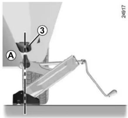
Vehicles equipped with a jack and wheelbrace
If necessary, remove the wheel trim.
- Unlock the wheel bolts using wheel-brace 4. Position it so as to be able to push from above;
- crank up jack 1 by hand to position the jack head against jacking point 3 closest to the wheel concerned and, depending on the vehicle, marked by an arrow 2.
- continue to crank the jack so that the baseplate is correctly positioned (it should be underneath the vehicle and aligned with jack head A);
- turn the wheelbrace until the wheel lifts off the ground;
If the vehicle is not equipped with a jack or wheelbrace, you can obtain these from your approved dealer.

To prevent any risk of injury or damage to the vehicle, only crank the jack until the wheel you are replacing is
a maximum of 3 centimetres off the ground.
CHANGING A WHEEL (2/2)
- undo the bolts and take off the wheel;
- fit the emergency spare wheel on the central hub and turn it to align the mounting holes in the wheel and the hub;
- tighten the bolts and lower the jack;
- with the wheel on the ground, tighten the screws as fully as possible and check the tightness as soon as possible (tightening torque 105 N.m).

If you have a puncture, replace the wheel as soon as possible.
A tyre which has been punctured should always be inspected (and repaired, where possible) by a specialist.
Anti-theft bolt
If you use anti-theft bolts, fit these nearest the valve (otherwise it may not be possible to fit the wheel trim).

If the vehicle is parked on the hard shoulder, you must warn other road users of your vehicle's presence
with a warning triangle or with other devices as per the legislation applying to the country you are in.
TYRES (1/3)
Tyre and wheel safety
The tyres are the only contact between the vehicle and the road, so it is essential to keep them in good condition.
You must make sure that your tyres conform to local road traffic regulations.

When they need to be replaced, only tyres of the same make, size, type and profile should be used.
Tyres fitted to the vehicle should either be identical to those fitted originally or conform to those recommended by your approved dealer.

Maintaining the tyres
The tyres must be in good condition and have sufficient depth to the tread. Tyres approved by our Technical Department have wear warning strips 1 in the form of raised strips moulded into the tread at several points.
When the tyre tread has been worn to the level of the wear indicators, they become visible 2: it is then necessary to replace your tyres because the tread rubber is no more than 1.6 mm deep, resulting in poor roadholding on wet roads.
An overloaded vehicle, long journeys by motorway, particularly in very hot weather, or continual driving on poorly surfaced minor roads will lead to more rapid tyre wear and affect safety.

Incidents which occur when driving, such as striking the kerb, may damage the tyres and wheel rims, and could
also lead to misalignment of the front or rear axle geometry. In this case, have the condition of these checked by an approved dealer.
TYRES (2/3)
Tyre pressures
Tyre pressures must be adhered to (remember to check the emergency spare wheel at the same time). Inflation pressures must be checked at least once a month and always before a long journey (refer to the information on "Tyre pressures").

Incorrect tyre pressures lead to abnormal tyre wear and unusually hot running.
These are factors which
may seriously affect safety and lead to:
– poor road holding, – the risk of blow-outs or of throwing a tread.
The pressure depends on the load and the speed of use. Adjust the pressures according to the conditions of use (refer to the information on “Tyre pressures”).
Pressures should be checked when the tyres are cold; ignore higher pressures which may be reached in hot weather or following a fast journey.
If tyre pressures cannot be checked when the tyres are cold, the normal pressures must be increased by 0.2 to 0.3 bar (or 3 psi).
Never deflate a hot tyre.
Note: a label (depending on country or model) fixed to the edge or frame of the driver's door gives the recommended tyre pressures.

Please be aware that a poorly tightened or missing valve cap can make the tyres less airtight and lead to pressure loss.
Always use valve caps identical to those fitted originally and tighten them fully.
Emergency spare wheel
Refer to the information on the "Emergency spare wheel" and instructions on "Changing a wheel" in Section 5.
Changing wheels around
This practice is not recommended.
Fitting new tyres

For safety reasons, this operation must be carried out by a specialist.
Fitting different tyres may affect your vehicle as follows:
- It may mean that your vehicle no longer conforms to current regulations;
- It may change the way it handles when cornering;
- It may cause the steering to be heavy; – It may cause tyre noise;
- It may affect the use of snow chains.
TYRES (3/3)
Use in winter
- Chains
For safety reasons, fitting snow chains to the rear axle is strictly forbidden.
Chains cannot be fitted to tyres which are larger than those originally fitted to the vehicle.

Chains may only be fitted to tyres of the same size as those originally fitted to your vehicle.
Chains may be fitted, provided that they are specific chains. We would advise you to consult an approved dealer.
- Snow or winter tyres
We would recommend that these be fitted to all four wheels to ensure that your vehicle retains maximum adhesion.
NB: We would point out that these tyres may sometimes have:
- a specific direction of rotation,
- a maximum speed index which may be lower than the maximum speed of your vehicle.
- Studded tyres
This type of equipment may only be used for a limited period and as laid down by local legislation.
It is necessary to observe the speed specified by current legislation.
These tyres must, at a minimum, be fitted to the two front wheels.
In all cases, we would recommend that you contact an approved dealer who will be able to advise you on the choice of equipment which is most suitable for your vehicle.

Changing a wheel
As the tyre pressure monitor may take several minutes following driving to cor-
rectly determine the positions of the wheels and the pressure values, check the tyre pressures following any operation.
HALOGEN HEADLIGHTS: changing bulbs
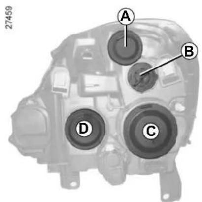
Due to their reduced accessibility, (sometimes requiring the removal of bodywork or mechanical components) we advise you to have your bulbs replaced by an approved Dealer.

Front side light
Remove cover A, then unclip bulb holder 1 to access the bulb.
Bulb type: W5W.
Replace the bulb.
Clip bulb holder 1 back onto the head-light.
Refit cover A.
To comply with local legislations, or as a precaution, you can obtain an emergency kit containing a set of spare bulbs and fuses from your Approved dealer.

The bulbs are under pressure and can break when replaced.
Risk of injury.
Direction indicator lights
Turn cover B a quarter of a turn to access the bulb.
Bulb type: PY21W.
Replace the bulb.
When the bulb has been changed, make sure you refit the cover correctly.

The engine may be hot when carrying out operations in close proximity. In addition, the engine cooling
fan can come on at any moment.
Risk of injury.
HALOGEN HEADLIGHTS: changing bulbs (continued)

Dipped beam/main beam headlights
Remove cover C or D.
Remove connector 4 or 6 from the bulb concerned.
Unclip clip 3 or 7.
Replace the bulb.
Bulb type: only use anti UV 55W bulbs to ensure the plastic glass on the headlights is not damaged.
5 → H7 or H1 depending on the vehicle
2 → H1

Refit connector 4 or 6.
Do not touch the bulb glass. Hold it by its base.
Refit clip 3 or 7, then cover C or D.

The engine may be hot when carrying out operations in close proximity. In addition, the engine cooling
fan can come on at any moment.
Risk of injury.

The bulbs are under pressure and can break when replaced.
Risk of injury.
HEADLIGHTS: additional/front fog lights

Front fog lights 1
Because it is sometimes necessary to remove the protectors (bumper), you are advised to have your bulbs replaced by an Approved dealer.
Bulb type: H11.

The engine may be hot when carrying out operations in close proximity. In addition, the engine cooling
fan can come on at any moment.
Risk of injury.
Additional lights
If you wish to fit fog lights or long range headlights to your vehicle, consult an approved Dealer.

Any operation on (or modification to) the electrical system must be performed by an approved Dealer since an incorrect connection might damage the electrical equipment (harness, components and in particular the alternator). In addition, your Dealer has all the parts required for fitting these units.

Vehicles with cornering lights 2
Due to their reduced accessibility, (sometimes requiring the removal of bodywork or mechanical components) we advise you to have your bulbs replaced by an approved Dealer.
Bulb type: H1.
REAR LIGHTS AND SIDE LIGHTS: changing bulbs (1/2)

Direction indicator lights/side lights and brake lights
After opening the tailgate, open the flap of the light concerned.
To remove the rear lights unit, undo nut 1.

The bulbs are under pressure and can break when replaced.
Risk of injury.

Release the rear light assembly from outside the vehicle by pulling towards the rear.
To access the bulbs, unclip the bulb holder by pressing the two clips 2.
Replace the bulbs.
Clip bulb holder 2 back on.
Refit the rear lights unit.
Retighten nut 1, holding the rear lights unit in its position and check that it is secure.

3 Brake light P21 W bulb.
4 Direction indicator lights PY21 W bulb.
5 Side light R5 W bulb.
6 Reversing light P21W bulb.
7 Rear fog light P21 W bulb. Note: both light units are fitted with a bulb, but only the bulb on the driver's side works.
REAR LIGHTS AND SIDE LIGHTS: changing bulbs (2/2)

High-level brake light 8
Consult an approved Dealer.

Number plate lights 9
Unclip light 9 by pressing the tab.
Remove the light cover to gain access to the bulb.
Bulb type: C5W festoon bulb.

Side indicator lights 10
Unclip the side mounted indicator light (using a flat-blade screwdriver or similar).
Turn the bulb holder a quarter of a turn and take out the bulb.
Bulb type: WY5W.

The bulbs are under pressure and can break when replaced.
Risk of injury.
INTERIOR LIGHTS: changing bulbs (1/2)

Courtesy light
Unclip the lens (using a flat-blade screwdriver or similar).
Remove the bulb concerned.
Bulb type 1: W5W.

Underfloor storage compartments lights 2
Unclip the light (using a flat-blade screwdriver or similar).
Turn the bulb holder a quarter of a turn and take out the lamp.
Bulb type: W5W.

The bulbs are under pressure and can break when replaced.
Risk of injury.
INTERIOR LIGHTS: changing bulbs (2/2)

Luggage compartment light
Unclip light 3 by pressing the tabs on each side (using a flat-blade screwdriver or similar).
Disconnect the light.

Press tab 4 to release the bulb holder and gain access to bulb 5.
Bulb type: C5W festoon bulb.

The bulbs are under pressure and can break when replaced.
Risk of injury.
FUSES (1/2)
Fuse box
If any electrical equipment does not work, check the condition of the fuses.
Unclip cover A or B (depending on vehicle).
To identify the fuses, refer to the fuse allocation label (shown on the following page).


Check the fuse in question and replace it, if necessary, with a fuse of the same rating.
If a fuse is fitted where the rating is too high, it may cause the electrical circuit to overheat (risk of fire) in the event of an item of equipment using an excessive amount of current.

Remove the fuse using tweezers 1, located on the cover.
To remove the fuse from the tweezers, slide the fuse to the side.
It is not advisable to use the free fuse locations.
In accordance with local legislation or as a precautionary measure:
Obtain an emergency kit containing a set of spare bulbs and fuses from an approved Dealer.
FUSES (2/2)
Allocation of fuses (the presence of fuses depends on the vehicle equipment level)
| Symbol | Allocation Symbol Allocation | ||
| Rear electric windows and door locking | Manual air conditioning | ||
| Automatic wipe/wash | Cigar lighter | ||
| ALIM UCH | Main power supply | ABS | |
| Central door locking | Electric windows | ||
| Heated door mirrors | Courtesy lights | ||
| Windscreen wiper | Horn | ||
| STOP | Brake switch | INJECT | Injection |
| Radio | Instrument panel/air conditioning control panel | ||
| Automatic climate control | Consumer cut-out |
Some functions are protected by the fuses located in the engine compartment.
However, because of their reduced accessibility, we advise you to have your fuses replaced by an approved dealer.
BATTERY: troubleshooting (1/3)
To avoid all risk of sparks:
- Ensure that all electrical equipment is switched off before disconnecting or reconnecting the battery.
- When charging, stop the charger before connecting or disconnecting the battery.
- Do not place metal objects on the battery to avoid creating a short circuit between the terminals.
- Wait at least 20 seconds after switching off the engine to disconnect the battery.
- Make sure that you reconnect the battery terminals after refitting.

Access to the battery
Depending on the vehicle, unclip then pull unit A in the engine compartment.
Unclip cover B and remove it. Then unclip cover C and remove it.

Refitting the battery covers
- Position cover C in its hinges and clip it in place.
- Position cover B in its hinges and clip it in place.
Check that the two covers B and C are correctly locked.
Depending on the vehicle, reposition unit A, tilting it forwards, then clip it in place by tilting it backwards. Check that it is correctly locked.

Handle the battery with care as it contains sulphuric acid, which must not come into contact with eyes or skin. If it does, wash the affected area with plenty of cold water.
Ensure that naked flames, red hot objects and sparks do not come into contact with the battery as there is a risk of explosion.
Take care when working in the engine compartment as the engine cooling fan may start to operate at any moment without warning, which may cause serious injury.
BATTERY: troubleshooting (2/3)
Connecting a battery charger
The battery charger must be compatible with a battery with a nominal voltage of 12 volts.
Switch the engine off and then disconnect both battery leads starting with the negative terminal.
Do not disconnect the battery when the engine is running. Follow the instructions given by the manufacturer of the battery charger you are using.
Only a fully charged and well-maintained battery will have a long and useful life and enable you to start the vehicle's engine normally.
The battery must be kept clean and dry.
Have the battery's charge status checked regularly:
- Especially if you use your vehicle for short journeys or for frequent driving in town.
- When the exterior temperature drops (in winter), the charge decreases. In winter, only use electrical equipment which is really necessary.
- Finally, you should understand that the charge decreases naturally as a result of certain permanent electrical consumers such as the clock, after-sales accessories, etc.
When many accessories are fitted to the vehicle, have them connected to the + after ignition feed. In this case, it is advisable to have your vehicle fitted with a battery which has an increased nominal capacity. Contact your approved dealer.
If your vehicle is to be left stationary for a relatively long time, disconnect the battery or have it recharged regularly, particularly during cold weather. It will then be necessary, with the engine running, to move the steering wheel slowly, from lock to lock and to reprogram the electronic equipment with a memory feature, radio, etc. The battery should be stored in a cool and dry location protected from frost.

Special procedures may be required to charge some batteries. Contact your approved Dealer.
Avoid all risk of sparks which may cause an immediate explosion, and charge the battery in a well-ventilated area.
Risk of serious injury.
BATTERY: troubleshooting (3/3)
Starting the vehicle using the battery from another vehicle
Proceed as follows when starting your vehicle from another vehicle's battery:
Obtain suitable jump leads (large) from an approved Dealer or, if you already have jump leads, ensure that they are in perfect condition.
The two batteries must have an identical nominal voltage of 12 volts. The battery supplying the current should have a capacity (amp-hours, Ah) which is at least the same as that of the discharged battery.
Ensure that there is no risk of contact between the two vehicles (risk of short circuiting when the positive terminals are connected) and that the discharged battery is properly connected. Switch off your vehicle ignition.
Start the engine of the vehicle supplying the current and run it at an intermediate engine speed.

Attach the positive lead A to the (+) terminal 1 of the discharged battery, then to the (+) terminal 2 of the battery supplying the current.
Attach the negative lead B to the (-) terminal 3 of the battery supplying the current, then to the (-) terminal 4 of the discharged battery.
Start the engine as you would normally. As soon as it is running, disconnect leads A and B in the reverse order (4-3-2-1).

Check that there is no contact between leads A and B and that the positive lead A is not touching any metal
parts on the vehicle supplying the current.
Risk of injury and/or damage to the vehicle.
RADIO FREQUENCY REMOTE CONTROL: battery
A
522A
Remote controls A and B
Replacing the battery
Remove screw 1. Open the case at slot 2 using a coin, and replace battery 3, observing the polarity shown on the back of the cover.
When refitting, ensure that the cover is correctly clipped on and the screw tightened.
A
522B
Note: It is not advisable to touch the electrical circuit in the key cover when replacing the battery.
Batteries can be obtained from your approved Dealer.
These batteries should have a service life of approximately two years.

Do not dispose of your used batteries in the countryside. Give them to an organisation that collects and recycles used batteries.
27416 B
26913
FITTING THE RADIO

Radio location 1
Unclip the blanking cover. The aerial, + and - supply and speaker wire connections are located behind it.

Tweeter speakers
Using a flat-blade screwdriver or similar, unclip grille 2 to access the speaker wires.

Door speakers
Using a flat-blade screwdriver or similar, unclip grille 3 to access the speaker wires.
- In all cases, it is very important to follow the manufacturer's instructions carefully.
- The specifications of the brackets and wires (available from our network) vary depending on the equipment level of your vehicle and the type of radio. Consult an approved Dealer to find out the correct part number.
- No work may be carried out on the vehicle's electrical or radio circuits, except by approved dealers: an incorrectly connected system may result in damage being caused to the electrical equipment and/or the components connected to it.
ACCESSORIES

Electrical and electronic accessories
Before installing this type of accessory, make sure it is compatible with your vehicle. You can get advice from an authorised dealer.
Connect accessories with a maximum power of 120 watts only. Fire hazard.
No work may be carried out on the vehicle's electrical or radio circuits, except by authorised dealers: an incorrectly connected system may result in damage being caused to the electrical equipment and/or the components connected to it.
If the vehicle is fitted with any aftermarket electrical equipment, make sure that the installation is correctly protected by a fuse. Establish the rating and position of this fuse.
Use of transmission/receiving devices (telephones, CB equipment etc.).
Telephones and CB equipment with integrated aerials may cause interference to the electronic systems originally fitted to the vehicle: it is advisable only to use equipment with an external aerial. Furthermore, we remind you of the need to conform to the legislation in force concerning the use of such equipment.
Fitting after-market accessories
If you wish to install accessories on the vehicle: please contact an authorised dealer. Also, to ensure the correct operation of your vehicle, and to avoid any risk to your safety, we recommend that you use only accessories specifically designed for your vehicle, which are the only accessories for which the manufacturer will provide a warranty.
If you are using an anti-theft device, only attach it to the brake pedal.
Obstructions to the driver
On the driver's side, only use mats suitable for the vehicle, attached with the pre-fitted components, and check the fitting regularly. Do not lay one mat on top of another. There is a risk of wedging the pedals
WINDSCREEN WIPER BLADES

Replacing windscreen wiper blades 1
- With the ignition off, lift the wiper arm 3;
- move blade 1 into a horizontal position;
- slide blade 1 until catch 2 on the wiper arm is released.
Refitting
To refit the wiper blade, proceed in reverse order to removal. Make sure that the blade is correctly locked in position.
Check the condition of the wiper blades. You are responsible for their service life:
- Clean the blades, windscreen, and rear screen regularly with soapy water;
- Do not use them when the windscreen or rear screen are dry;
- Free them from the windscreen or rear screen when they have not been used for a long time.

In frosty weather, make sure that the wiper blades are not stuck by ice (to avoid the risk of the motor heating).
Check the condition of the wiper blades.
Replace the wiper blades as soon as they begin to lose efficiency (approximately once a year).
While changing the blade, take care not to drop the arm onto the window after it has been removed, as this may break the window.

Rear screen wiper blade 4
- With the ignition off, lift the wiper arm 5;
- Pivot blade 4 until some resistance is met; remove the blade by pulling it.
Refitting
To refit the wiper blade, proceed in reverse order to removal. Make sure that the blade is correctly locked in position.
TOWING: breakdown
Insert the key into the ignition switch to unlock the steering wheel and to use the indicator lights (brake lights, indicators, etc.). The towed vehicle's lights must be switched on at night.
Furthermore, it is essential to respect the towing regulations set out in the legislation of the country concerned and, if your vehicle is the towing vehicle, to not exceed the towing weight of your vehicle. Contact your approved Dealer.
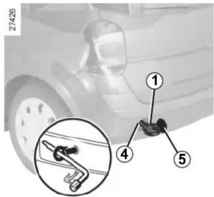
Only use the front 2 and rear 4 towing points (never use the drive-shafts). These towing points may only be used for towing: never use them for lifting the vehicle directly or indirectly.

When the engine is stopped, steering and braking assistance are not operational.
Access to towing points
Unclip cover 3 or 5 using a flat-blade screwdriver or similar.
Screw in towing hitch 1 fully: as much as possible by hand at first, then finish by tightening it using the wheel-brace.
Towing hitch 1 and the wheelbrace are located under the luggage compartment carpet in the tool kit (refer to the information on the "Tool kit" in Section 5).

Do not leave tools loose in the vehicle: there is a risk they may be thrown about during braking.
TOWING: breakdown (continued)
Towing a vehicle with an automatic gearbox
With the engine switched off: the gearbox is no longer lubricated. It is preferable to tow this type of vehicle on a trailer or tow it with the front wheels off the ground.
Under exceptional circumstances, you may tow the vehicle with all four wheels on the ground, only going forward, with the gear lever in the neutral position N and for a distance not exceeding 30 miles (50 km).

- Use a rigid towing bar. If a rope or cable is used (where the law allows this), the vehicle being towed must be able to brake.
- A vehicle must not be towed if it is not fit to be driven.
- Avoid accelerating or braking suddenly when towing, as this may result in damage being caused to the vehicle.
- When towing a vehicle, it is advisable not to exceed 15 mph (25 km/h).

If the lever is stuck in P, even though you are depressing the brake pedal, the lever can be released
manually.
To do this, unclip the upper section of the cover at the base of the lever.
Press simultaneously on the mark on the gaiter and the unlocking button on the lever.
Towing a vehicle with a Quickshift gearbox
If a gear is engaged:
– with the ignition on, select neutral while depressing the brake pedal, – check that neutral is engaged (e.g. by pushing the vehicle), - switch off the ignition.
The vehicle should always be towed with the ignition switched off.
If you cannot engage neutral, the vehicle must be towed with its front wheels off the ground.
TRANSPORTING OBJECTS: towbar

A: 614 mm (normal chassis) A: 681 mm (long chassis)
Permissible nose weight, maximum permissible towing weight, braked and unbraked: refer to the information on "Weights" in Section 6.
For fitting and conditions of use, refer to the equipment's fitting instructions.
Please keep these instructions with the rest of the vehicle documentation.
If the towbar ball obscures the registration plate or the rear fog lights, it should be removed when not in use. In all cases, comply with local legislation.
OPERATING FAULTS (1/5)
The following advice will enable you to carry out quick, temporary repairs. For safety reasons you should always contact an approved Dealer as soon as possible.
The starter is activated POSSIBLE CAUSES WHAT TO DO
| The indicator lights fail to light up and the starter does not turn. | Battery terminals disconnected, oxidised or incorrectly secured. | Retighten, reconnect or clean them if they are oxidised. |
| Battery discharged or unservice-able. | Connect another battery to the faulty bat-tery. Refer to the paragraph “Battery: trou-bleshooting” in section 5 or replace the bat-tery if necessary.Do not push the vehicle if the steering column is locked. | |
| The engine will not start. | Starting conditions are not fulfilled. | Refer to the information on “Starting/stop-ping the engine” in Section 2. |
| The steering column remains locked. | Steering wheel locked. | To unlock, move the key and the steering wheel gently (refer to the information on the “Ignition switch” in Section 2). |
OPERATING FAULTS (2/5) On the road POSSIBLE CAUSES WHAT TO DO
| Coolant boiling in the coolant reservoir. | Mechanical fault: cylinder head gasket damaged, faulty coolant pump. | Stop the engine.Contact an approved Dealer. |
| Smoke under the bonnet. | Short circuit or cooling system leak. | Stop, switch off the ignition, stand away from the vehicle and contact an approved Dealer. |
The oil pressure warning light comes on:
while cornering or braking The level is too low. Top up the engine oil (refer to the information on "Engine oil level - Topping up/refilling" in Section 4).
tion on "Engine oil level - Topping up/refilling" in Section 4).
At idle speed, low oil pressure. Consult the nearest approved dealer.
is slow to go out or remains lit under acceleration Loss of oil pressure. Stop the vehicle and contact an approved Dealer.
White smoke from the exhaust. This is not necessarily a fault. Smoke may be caused by regeneration of the particle filter.
Refer to the information on "Special features of diesel versions" in Section 2.
On the road POSSIBLE CAUSES WHAT TO DO
Radiator: If there is a significant lack of coolant, remember that it must never be topped up using cold coolant while the engine is very warm. After any procedure on the vehicle which has involved even partial draining of the cooling system, it must be refilled with a new mixture prepared in the correct proportions. Reminder: only products approved by our Technical Department may be used for this purpose.
| Vibrations Tyres not inflated to correct pressures, incorrectly balanced or damaged. | Check the tyre pressures: if this is not the problem, have them checked by an approved dealer. |
| whistling roof aerial incorrectly positioned Fold down the aerial until the end of it is approximately 44 cm from the vehicle's roof. | |
| Steering becomes heavy. Assistance overheating.Low battery. | Leave to cool.Recharge or replace the battery. |
| The engine overheats. The coolant temperature indicator and the STOP warning light come on. | Engine cooling fan not working. Stop the vehicle, switch off the engine and contact an approved Dealer.Coolant leaks. Check the coolant reservoir: it should contain fluid. If there is no coolant, consult your approved Dealer as soon as possible. |

Radiator: If there is a significant lack of coolant, remember that it must never be topped up using cold coolant while the engine is very warm. After any procedure on the vehicle which has involved even partial draining of the cooling system, it must be refilled with a new mixture prepared in the correct proportions. Reminder: only products approved by our Technical Department may be used for this purpose.
OPERATING FAULTS (4/5)
Electrical equipment POSSIBLE CAUSES WHAT TO DO
The wipers do not work. Wiper blades stuck. Free the blades before using the wipers.
Faulty electrical circuit. Consult an approved Dealer.
The wiper does not stop. Faulty electrical controls. Consult an approved Dealer.
Direction indicators flashing more Blown bulb. Replace the bulb quickly.
The direction indicators do not work. Faulty electrical circuit. Consult an approved Dealer.
The headlights do not switch on or off. Faulty electrical circuit or control. Consult an approved Dealer.
Traces of condensation in the lights. This is not a fault. Traces of condensation are a natural phenomenon caused by variations in temperature. These traces soon disappear when the lights are switched on.
OPERATING FAULTS (5/5)
Electrical equipment POSSIBLE CAUSES WHAT TO DO
The sunroof does not open/close. Sunroof opening conditions not fulfilled.
Apply the opening conditions (refer to the information on the "Electric sunroof" in Section 3).
Roof fault.
Electrical fault (discharged battery, etc.).
Leave the sunroof closed or close it using the methods described in "Electric sunroof: Operating fault" in Section 3 and contact your approved dealer.
Section 6: Technical specifications
Vehicle identification plates 6.2
Engine identification plates 6.3
Dimensions 6.4
Engine specifications.... 6.5
Weights 6.6
Replacement parts and repairs 6.7
Service sheets.... 6.8
Anti-corrosion check 6.14
6.1
VEHICLE IDENTIFICATION PLATES


The information shown on the vehicle identification plate should be quoted on all correspondence or orders.
The presence and location of the information depends on the vehicle.
Vehicle identification plate A
1 Vehicle type and chassis number. Depending on the vehicle, this information is also given on marking B. 2 MMAC (Maximum permissible all-up weight). 3 GTW (Gross train weight: vehicle fully loaded, with trailer).
4 MMTA (Maximum permissible all-up weight) front axle. 5 MMTA (Maximum permissible all-up weight) rear axle. 6 Technical specifications of vehicle. 7 Paint reference. 8 Equipment level. 9 Vehicle type. 10 Trim code. 11 Additional equipment specification. 12 Production number. 13 Interior trim code.
ENGINE IDENTIFICATION PLATES![graph TD A["①"] --> B["000 0 000"] C["②"] --> D["0 000000"] E["③"] --> F["0 000000"]](/content/2026/06/1312194/images/01b28a693be9e26e6da009489cdb2d695fa2a9610f46c1b1b94c8ce114d35a2f.jpg)
The information on the engine plate or label A should be quoted on all your correspondence or orders.
(Location varies depending on engine)
1 Engine type. 2 Engine suffix. 3 Engine number.


DIMENSIONS (in metres)
Standard chassis

Long chassis

* Unladen 6.4
ENGINE SPECIFICATIONS
| Versions 1.2 16V 1.2 16V TCE 1.4 16V 1.6 16V | 1.5 dCi | ||||
| Engine type(see engine plate) | D4F D4F Turbo K4J K4 | M K9K Turbo | |||
| Cubic capacity (cc) 1 149 1 390 1 598 1 461 | |||||
| Type of fuelOctane rating | It is essential that you use unleaded petrol of the octane rating stated on the label inside the fuel filler flap.If not available, for a limited time only, use unleaded fuel:– with an octane rating of 91 for a label with the ratings 95 or 98,– with an octane rating of 87 for a label showing 91, 95 or 98. | Diesel: the label located in the fuel filler flap indicates authorised fuels. | |||
| Spark plugs | Only use the spark plugs specified for your vehicle's engine.The type should be marked on a label stuck inside the engine compartment. If it is not then contact your RENAULT Dealer.Fitting spark plugs which are not to specification may damage the engine. | – | |||
WEIGHTS (in kg)
The weights indicated for a basic vehicle without options: they vary depending on the your vehicle's equipment. Consult your approved Dealer.
| 5-door versions Utility versions | ||
| Maximum permissible all-up weight (MMAC)Total train weight (MTR) | Weights indicated on the manufacturer's plate (refer to chapter 6 “Vehicle identification plate”) | |
| Braked trailer weight* obtained by calculating: MTR | - MMAC | |
| Unbraked trailer weight* 500 535 | ||
| Permissible nose weight* 75 25 | ||
| Permissible load on the roof with the carrying device | 80 kg (including the carrying device) | |
* Towing weight (towing a caravan, boat, etc.)
Towing is prohibited when the GTW - MAM calculation is equal to zero, or when the GTW is equal to zero (or is not listed) on the identification plate.
- It is important to comply with the towing weights, governed by local legislation in each country and, in particular, laid down in the Road Traffic Regulations. Contact an approved Dealer about any towing equipment.
- When towing, under no circumstances may the total train weight (vehicle + trailer) be exceeded. However, the following is permitted:
– The maximum permissible weight at the rear may be exceeded by no more than 15%,
– The maximum permissible all-up weight may be exceeded by no more than 10% or 100 kg (whichever occurs first).
In either case, the maximum speed of the vehicle and trailer must not exceed 50 mph (80 km/h) for utility versions, or 100 mph (60 km/h) for 5-door versions, and the tyre pressure must be increased by 0.2 bar (3 PSI).
- The engine output and climbing capability are reduced with altitude. We recommend that the maximum load be reduced by 10% at an altitude of 1,000 metres and by an additional 10% for each 1,000 metres thereafter.
Load transfer (except for utility versions)
If the Maximum Authorised Mass of the vehicle has not been reached, up to 300 kg can be transferred to the braked trailer, within the limits of the Gross Train Weight.
REPLACEMENT PARTS AND REPAIRS
Original parts are based on strict specifications and are subject to highly-specialised tests. Therefore, they are of at least the same level of quality as the parts fitted originally.
If you always fit genuine replacement parts to your vehicle, you will ensure that it performs well. Furthermore, repairs carried out within the manufacturer's Network using original parts are guaranteed according to the conditions set out on the reverse of the repair order.
SERVICE SHEETS
VIN:
| Date: Miles (km): Invoice number: Comments/miscellaneous | ||
| Type of operation: Stamp Service...... □ | ||
| Anticorrosion check: OK □ Not OK* □*See specific page | ||
| Date: Miles (km): Invoice number: Comments/miscellaneous | ||
| Type of operation: Stamp Service...... □ | ||
| Anticorrosion check: OK □ Not OK* □*See specific page | ||
| Date: Miles (km): Invoice number: Comments/miscellaneous | ||
| Type of operation: Stamp Service...... □ | ||
| Anticorrosion check: OK □ Not OK*, □*See specific page | ||
SERVICE SHEETS (continued)
VIN:
| Date: Miles (km): Invoice number: Comments/miscellaneous | ||
| Type of operation: Stamp Service...... □ | ||
| Anticorrosion check: OK □ Not OK* □*See specific page | ||
| Date: Miles (km): Invoice number: Comments/miscellaneous | ||
| Type of operation: Stamp Service...... □ | ||
| Anticorrosion check: OK □ Not OK* □*See specific page | ||
| Date: Miles (km): Invoice number: Comments/miscellaneous | ||
| Type of operation: Stamp Service...... □ | ||
| Anticorrosion check: OK □ Not OK*, □*See specific page | ||
SERVICE SHEETS (continued)
| Date: Miles (km): Invoice number: Comments/miscellaneous | ||
| Type of operation: Stamp Service...... □ | ||
| Anticorrosion check: OK □ Not OK* □*See specific page | ||
| Date: Miles (km): Invoice number: Comments/miscellaneous | ||
| Type of operation: Stamp Service...... □ | ||
| Anticorrosion check: OK □ Not OK* □*See specific page | ||
| Date: Miles (km): Invoice number: Comments/miscellaneous | ||
| Type of operation: Stamp Service...... □ | ||
| Anticorrosion check: OK □ Not OK*, □*See specific page | ||
SERVICE SHEETS (continued)
| Date: Miles (km): Invoice number: Comments/miscellaneous | ||
| Type of operation: Stamp Service...... □ | ||
| Anticorrosion check: OK □ Not OK* □*See specific page | ||
| Date: Miles (km): Invoice number: Comments/miscellaneous | ||
| Type of operation: Stamp Service...... □ | ||
| Anticorrosion check: OK □ Not OK* □*See specific page | ||
| Date: Miles (km): Invoice number: Comments/miscellaneous | ||
| Type of operation: Stamp Service...... □ | ||
| Anticorrosion check: OK □ Not OK*, □*See specific page | ||
SERVICE SHEETS (continued)
| Date: Miles (km): Invoice number: Comments/miscellaneous | ||
| Type of operation: Stamp Service...... □ | ||
| Anticorrosion check: OK □ Not OK* □*See specific page | ||
| Date: Miles (km): Invoice number: Comments/miscellaneous | ||
| Type of operation: Stamp Service...... □ | ||
| Anticorrosion check: OK □ Not OK* □*See specific page | ||
| Date: Miles (km): Invoice number: Comments/miscellaneous | ||
| Type of operation: Stamp Service...... □ | ||
| Anticorrosion check: OK □ Not OK*, □*See specific page | ||
SERVICE SHEETS (continued)
| Date: Miles (km): Invoice number: Comments/miscellaneous | ||
| Type of operation: Stamp Service...... □ | ||
| Anticorrosion check: OK □ Not OK* □*See specific page | ||
| Date: Miles (km): Invoice number: Comments/miscellaneous | ||
| Type of operation: Stamp Service...... □ | ||
| Anticorrosion check: OK □ Not OK* □*See specific page | ||
| Date: Miles (km): Invoice number: Comments/miscellaneous | ||
| Type of operation: Stamp Service...... □ | ||
| Anticorrosion check: OK □ Not OK*, □*See specific page | ||
ANTICORROSION CHECK
If the continuation of the warranty is subject to repair, it is indicated below.
VIN: ....
| Corrosion repair operation to be carried out: |  | Stamp |
| Date of repair: | ||
| Repair to be carried out: |  | Stamp |
| Date of repair: | ||
| Repair to be carried out: |  | Stamp |
| Date of repair: | ||
ANTICORROSION CHECK (continued)
If the continuation of the warranty is subject to repair, it is indicated below.
VIN: ....
| Corrosion repair operation to be carried out: | | Stamp |
| Date of repair: | ||
| Repair to be carried out: | | Stamp |
| Date of repair: | ||
| Repair to be carried out: |  | Stamp |
| Date of repair: | ||
ANTICORROSION CHECK (continued)
If the continuation of the warranty is subject to repair, it is indicated below.
| Corrosion repair operation to be carried out: |  | Stamp |
| Date of repair: | ||
| Repair to be carried out: |  | Stamp |
| Date of repair: | ||
| Repair to be carried out: |  | Stamp |
| Date of repair: | ||
ANTICORROSION CHECK (continued)
If the continuation of the warranty is subject to repair, it is indicated below.
| Corrosion repair operation to be carried out: | | Stamp |
| Date of repair: | ||
| Repair to be carried out: | | Stamp |
| Date of repair: | ||
| Repair to be carried out: |  | Stamp |
| Date of repair: | ||
ANTICORROSION CHECK (continued)
If the continuation of the warranty is subject to repair, it is indicated below.
| Corrosion repair operation to be carried out: |  | Stamp |
| Date of repair: | ||
| Repair to be carried out: |  | Stamp |
| Date of repair: | ||
| Repair to be carried out: |  | Stamp |
| Date of repair: | ||
ALPHABETICAL INDEX (1/5)
A
ABS 2.14
accessories.... 5.30
accessories socket 3.29
additional methods of restraint 1.26
side protection 1.25
to the front seat belts 1.20 → 1.23
to the rear seat belts 1.24
adjusting your driving position....1.13 → 1.19
advice on antipollution....2.10 → 2.12
air bag....1.20 → 1.26
activating the front passenger air bags 1.40
deactivating the front passenger air bags 1.38
air conditioning ....3.4 → 3.16
air vents 3.2 - 3.3
anti-corrosion check 6.14 → 6.18
anti-corrosion protection 4.13
anti-lock braking system: ABS 2.14
antipollution advice ....2.10 → 2.12
ashtray....3.29
automatic gearbox (use)....2.27 → 2.30
automatic gearbox selector lever....2.27 → 2.30
B
batteries....5.28
battery....4.12, 5.25 → 5.27
bonnet.... 4.2 - 4.3
brake fluid 4.9
bulbs changing ....5.16 → 5.22
C
catalytic converter.... 2.5 - 2.6
central door locking ....1.6, 1.9 → 1.11
changing a bulb 5.16 → 5.22
changing a wheel.... 5.11 - 5.12
changing gear....2.27 → 2.35
child restraint/seat 1.28, 1.30 → 1.37
child safety 1.2 - 1.3, 1.7 - 1.8, 1.23, 1.28, 1.30 → 1.40, 3.17, 3.20 - 3.21
child seats....1.28, 1.30 → 1.37
children 1.2 - 1.3, 1.7 - 1.8, 3.17
cigar lighter 3.29
cleaning: inside the vehicle 4.15 – 4.16
clock 1.62
closing the doors 1.7 - 1.8
control instruments ....1.46 → 1.53, 1.61 – 1.62
controls....1.42 → 1.45
coolant....4.8
courtesy light 3.23, 5.21
cruise control....2.23 → 2.26
cruise control-speed limiter....2.20 → 2.26
D
dashboard....1.42 → 1.45
de-icing rear screen 3.4
demisting rear screen .... 3.8, 3.13 – 3.14 windscreen.... 3.5, 3.14
dimensions 6.4
dipstick 4.5
display 1.46 → 1.51
doors/tailgate 1.2 - 1.3, 1.7 → 1.11, 3.36
driver's position 1.42 → 1.49
driving....2.2, 2.4 → 2.7, 2.9 → 2.12, 2.14 → 2.35
driving position settings 1.16
ALPHABETICAL INDEX (2/5)
E
electric windows 3.17
Electronic Stability Program: ESP 2.15 - 2.16
emergency brake assist.... 2.19
emergency braking 2.19
emergency spare wheel ....5.2 → 5.5
engine
Technical specifications 6.5
Engine immobiliser 1.12
Engine oil 4.4-4.5
Engine oil level 4.4 - 4.5
Engine specifications 6.5
Engine start/stop button 2.3 - 2.4
Environment 2.13
ESP: Electronic Stability Program 2.15 - 2.16
External temperature 1.63
F
Faults Operating faults 5.35 → 5.39
Filter Air filter 4.10
Diesel filter 4.10
Particle filter 2.7
Fitting a radio 5.29
fittings....3.24 → 3.28
fog lights 1.71, 5.18
front passenger air bag deactivation 1.38
front seat adjustment 1.15
front seats adjustment 1.15 – 1.16
fuel advice on fuel economy ....2.10 → 2.12
capacity 1.76 - 1.77
filling 1.76 - 1.77
grade 1.76 - 1.77
fuel economy....2.10 → 2.12
fuel level 1.46 → 1.49, 1.52 – 1.53
fuel tank capacity....1.76
fuel tank capacity 1.76 - 1.77
fuses 5.23 - 5.24
G
gear lever....2.8
glove box 3.24
H
handbrake 2.9
hazard warning lights signal 1.66
headlight beam adjustment 1.72
headlight flashers 1.66
headrest.... 1.13 - 1.14
heated seats 1.15
heating and air conditioning system ....3.8 → 3.16
heating system 3.4 → 3.16
horn 1.66
horn: flash .... 1.66 sounding the horn .... 1.66
hubcap tool 5.9 - 5.10
|
ignition switch 2.3
indicator lights.... 5.20
indicators 1.66, 5.16 - 5.17, 5.19 - 5.20
indicators: direction indicators .... 1.66 instrument panel .... 1.46 → 1.53
instrument panel 1.46 → 1.53, 1.61
interior trim maintenance 4.15 – 4.16
ALPHABETICAL INDEX (3/5)
J
jack 5.9
K
keys 1.2 → 1.5
L
levels 4.8
levels:
brake fluid 4.9
coolant 4.8
windscreen washer reservoir 4.10
lifting the vehicle
changing a wheel 5.11 - 5.12
lighting:
exterior....1.67 → 1.72
instrument panel 1.67
interior 3.23, 5.21 - 5.22
see-me-home....1.68
lights
additional 5.18
adjustment 1.72
changing bulbs 5.16 - 5.17
fog lights 5.18
front....5.16 → 5.18
lights:
adjusting 1.72
brake lights 5.19 - 5.20
dipped beam headlights 1.68, 5.16 - 5.17
direction indicators 1.66, 5.16 - 5.17, 5.19
fog lights 1.71, 5.18 - 5.19
hazard warning 1.66
main beam headlights 1.69, 5.16 - 5.17
number plate lights 5.20
reversing lights 5.19
side lights 1.67, 5.16 - 5.17, 5.19
lights-on warning buzzer 1.70
load permitted on the roof.... 6.6
locking the doors ....1.2 → 1.11
M
maintenance:
bodywork 4.13 - 4.14
interior trim 4.15 - 4.16
mechanical 4.4 - 4.5, 4.12, 6.8 → 6.13
mileage before service 6.8 → 6.13
map reading lights 3.23
methods of restraint in addition to the seat belts...1.20 → 1.26
0
opening the doors 1.7 - 1.8
operating faults....5.35 → 5.39
P
paintwork
maintenance 4.13 - 4.14
reference....6.2
parking distance control.... 2.36 - 2.37
power-assisted steering.... 2.8
practical advice....2.10 → 2.12
puncture....5.2 → 5.5
Q
Quickshift gearbox....2.31 → 2.35
R
rear bench seat....3.32 → 3.35
rear parcel shelf 3.37
rear screen
demisting 3.4, 3.8, 3.13
rear screen de-icing/demisting 3.7
rear seats.... 1.18
ALPHABETICAL INDEX (4/5)
functions 3.35 rear view mirrors 1.64 - 1.65 replacement parts 6.7 reverse gear selecting....2.8 roof bars 3.40 roof rack roof bars .... 3.40 running in .... 2.2
S
seat belt pretensioners front seat belt....1.20 → 1.23 seat belts....1.16 → 1.19 service sheets....6.8 → 6.13 signals and lights....1.67 → 1.72 speakers location 5.29 special features of diesel vehicles with particle filter 2.7 special features of diesel versions.... 2.6 special features of petrol vehicles 2.5 speed limiter....2.20 → 2.22 starting the engine 2.3-2.4 steering wheel adjustment 1.41 stopping the engine 2.4 storage compartment....3.24 → 3.28 storage compartments....3.24 → 3.28 sun visor 3.22 sunroof.... 3.20 - 3.21
tailgate....3.36 → 3.39
tanks and reservoirs coolant 4.8
tanks and reservoirs: windscreen washer 4.10 technical specifications 6.2-6.3, 6.5, 6.7 temperature regulation ....3.4 → 3.16 tool kit 5.9 towing breakdown .... 5.32 – 5.33 towing equipment .... 5.34 towing equipment fitting 5.34 towing hitch.... 5.32 towing rings 3.38 traction control: ASR 2.17 - 2.18 transporting children 1.28, 1.30 → 1.37 transporting objects in the luggage compartment .... 3.39 on the roof .... 6.6 trims....5.10 trip computer and warning system.... 1.52 - 1.53, 1.61 tyre inflation kit....5.6 → 5.8 tyre pressure.... 4.11, 5.14 tyre pressures 4.11 tyres....4.11, 5.13 → 5.15
unlocking the doors 1.9 - 1.10
variable power-assisted steering 2.8
vehicle identification 6.2 - 6.3
vehicle identification plates 6.2 - 6.3
ventilation 3.2 → 3.16
warning buzzer 1.7, 1.48, 1.50, 1.66
warning lights....1.46 → 1.53
ALPHABETICAL INDEX (5/5)
washing 4.13 - 4.14 wheelbrace 5.9 wheels (safety) 5.13 → 5.15 windscreen de-icing/demisting 3.13 windscreen washer....1.73 → 1.75 wiper blades 5.31 wipers 1.73 → 1.75 blades 5.31
RENAULT S.A.S SOCIÉTÉ PAR ACTIONS SIMPLIFIÉE AU CAPITAL DE 533 941 113 € / 13-15, QUAI LE GALLO 92100 BOULOGNE-BILLANCOURT R.C.S. NANTERRE 780 129 987 - SIRET 780 129 987 03591 / TÉL. : 0810 40 50 60 NU 815-10 - 8201030119 - 06/2012 - Edition ENG
8201030119
PK



- A PASSION FOR PERFORMANCE
- RENAULT RECOMMENDS ELF
- WELCOME TO YOUR NEW VEHICLE
- CONTENTS
- SECTIONS
- SECTION 1: GETTING TO KNOW YOUR VEHICLE
- KEY/RADIO FREQUENCY REMOTE CONTROL: GENERAL INFORMATION (1/2)
- KEY A
- RADIO FREQUENCY REMOTE CONTROL UNIT B OR C
- ADVICE
- KEY/RADIO FREQUENCY REMOTE CONTROL: GENERAL INFORMATION (2/2)
- RADIO FREQUENCY REMOTE CONTROL OPERATING RANGE
- INTERFERENCE
- DRIVER'S RESPONSIBILITY
- FOR REPLACEMENT, OR IF YOU REQUIRE AN ADDITIONAL REMOTE CONTROL
- REMOTE CONTROL UNIT FAILURE
- RADIO FREQUENCY REMOTE CONTROL: USE (1/2)
- UNLOCKING THE DOORS
- REMOTE CONTROL A OR B
- RADIO FREQUENCY REMOTE CONTROL: USE (2/2)
- LOCKING THE DOORS
- UNLOCKING/LOCKING THE TAILGATE ONLY
- DEADLOCKING
- DEADLOCKING OF THE DOORS/TAILGATE
- TO ACTIVATE DEADLOCKING
- OPENING AND CLOSING THE DOORS (1/2)
- LIGHTS-ON WARNING BUZZER
- DOOR/TAILGATE OPEN BUZZER
- OPENING AND CLOSING THE DOORS (2/2)
- CHILD SAFETY
- VEHICLES FITTED WITH SWITCH 3 WITH INTEGRATED INDICATOR LIGHT
- SAFETY OF REAR OCCUPANTS
- VEHICLE WITH MANUAL DOOR LOCKING
- DRIVER'S RESPONSIBILITY WHEN PARKING OR STOPPING THE VEHICLE
- LOCKING/UNLOCKING THE DOORS (1/2)
- LOCKING/UNLOCKING FROM THE OUTSIDE
- LOCKING/UNLOCKING THE DOORS (2/2)
- LOCKING/UNLOCKING DOORS FROM THE OUTSIDE (CONTINUED)
- LOCKING/UNLOCKING FROM THE INSIDE: BUTTON
- DOORS AND TAILGATE STATUS INDICATOR LIGHT
- AUTOMATIC LOCKING WHEN DRIVING
- TO ACTIVATE
- TO DEACTIVATE
- OPERATING PRINCIPLE
- OPERATING FAULTS
- ENGINE IMMOBILISER
- VEHICLE PROTECTION TELL-TALE LIGHT
- OPERATING FAULT WARNING LIGHT
- FRONT HEADRESTS
- TO LOWER THE HEADREST
- TO REMOVE THE HEADREST
- TO REFIT THE HEADREST
- REAR HEADRESTS
- POSITIONS FOR USE
- STORAGE POSITION
- FRONT SEATS
- TO TILT THE SEATBACK
- HEATED SEATS
- SEAT BELTS (1/4)
- ADJUSTING YOUR DRIVING POSITION
- ADJUSTING THE SEAT BELTS
- SEAT BELTS (2/4)
- TO FASTEN
- SEAT BELT REMINDER WARNING LIGHT
- UNLOCKING
- ADJUSTING THE HEIGHT OF THE SEAT BELT
- SEAT BELTS (4/4)
- METHODS OF RESTRAINT IN ADDITION TO THE FRONT SEAT BELTS (1/4)
- PRETENSIONERS
- METHODS OF RESTRAINT IN ADDITION TO THE FRONT SEAT BELTS (2/4)
- CHEST-LEVEL AND LAP BELT LOAD LIMITERS
- AIR BAGS FOR DRIVER AND FRONT PASSENGER
- METHODS OF RESTRAINT IN ADDITION TO THE FRONT SEAT BELTS (3/4)
- OPERATION
- SPECIAL FEATURE OF THE FRONT AIR BAG
- METHODS OF RESTRAINT IN ADDITION TO THE FRONT SEAT BELTS (4/4)
- WARNINGS CONCERNING THE DRIVER'S AIR BAG
- WARNINGS CONCERNING THE PASSENGER AIR BAG
- A CHILD SEAT MUST NOT BE FITTED TO THE FRONT PASSENGER SEAT UNLESS THE ADDITIONAL RESTRAINT SYSTEMS, I.E. THE PASSENGER AIR BAG, ARE DEACTIVATED
- METHODS OF RESTRAINT IN ADDITION TO THE REAR SEAT BELTS
- FORCE LIMITER
- SIDE PROTECTION DEVICES
- SIDE AIR BAGS
- CURTAIN AIR BAGS
- WARNINGS CONCERNING THE SIDE AIR BAG
- ADDITIONAL METHODS OF RESTRAINT
- CHILD SAFETY: GENERAL INFORMATION (1/2)
- CARRYING CHILDREN
- USING A CHILD SEAT
- CHILD SAFETY: GENERAL INFORMATION (2/2)
- CHILD SAFETY: CHOOSING A CHILD SEAT
- REAR-FACING CHILD SEATS
- FORWARD-FACING CHILD SEATS
- BOOSTER CUSHIONS
- CHILD SAFETY: CHOOSING A CHILD SEAT MOUNTING
- ATTACHMENT VIA THE SEAT BELT
- TRIPTIC REAR BENCH SEAT
- ATTACHMENT WITH THE ISOFIX SYSTEM
- CHILD SAFETY: CHOOSING A CHILD SEAT MOUNTING (CONTINUED)
- CHILD SAFETY: FITTING A CHILD SEAT (1/6)
- IN THE FRONT SEAT
- IN THE REAR SIDE SEAT
- IN REAR CENTRE SEAT
- INSTALLATION DIAGRAM (SLIDING BENCH SEATS)
- RISK OF DEATH OR SERIOUS INJURY: BEFORE
- CHILD SEAT ATTACHED USING THE BELT
- CHILD SEAT ATTACHED USING THE ISOFIX FITTING
- CHILD SAFETY: FITTING A CHILD SEAT (3/6)
- RISK OF DEATH OR
- CHILD SAFETY: FITTING A CHILD SEAT (4/6)
- INSTALLATION DIAGRAM (FIXED BENCH SEAT)
- CHILD SEAT ATTACHED USING THE ISOFIX MOUNTING
- CHILD SAFETY: FITTING A CHILD SEAT (6/6)
- CHILD SAFETY: DEACTIVATING/ACTIVATING THE FRONT PASSENGER AIR BAG (1/3)
- DEACTIVATING THE FRONT PASSENGER AIR BAGS (ON EQUIPPED VEHICLES)
- CHILD SAFETY: DEACTIVATING/ACTIVATING THE FRONT PASSENGER AIR BAG (2/3)
- DANGER
- CHILD SAFETY: DEACTIVATING/ACTIVATING THE FRONT PASSENGER AIR BAG (3/3)
- ACTIVATING THE FRONT PASSENGER AIR BAGS
- STEERING WHEEL
- STEERING WHEEL HEIGHT ADJUSTMENT
- DRIVER'S POSITION, LEFT-HAND DRIVE (CONTINUED)
- THE FITTINGS DESCRIBED DEPEND ON THE VEHICLE VERSION AND COUNTRY
- DRIVER'S POSITION, RIGHT-HAND DRIVE (CONTINUED)
- INSTRUMENT PANEL: WARNING LIGHTS (1/4)
- TOXIC FUME FILTER SYSTEM WARNING LIGHT
- INSTRUMENT PANEL: WARNING LIGHTS (2/4)
- OIL PRESSURE WARNING LIGHT
- BATTERY CHARGE WARNING LIGHT
- HANDBRAKE ON AND BRAKE CIRCUIT INCIDENT WARNING LIGHT
- FUEL ECONOMY INDICATOR LIGHTS
- INSTRUMENT PANEL: WARNING LIGHTS (3/4)
- AIR BAG WARNING LIGHT
- AUTOMATIC GEARBOX OPERATIONAL WARNING LIGHTS
- PARTICLE FILTER WARNING LIGHT
- ELECTRONIC STABILITY PROGRAM (ESP) AND TRACTION CONTROL
- WARNING LIGHT
- ENGINE IMMOBILISER SYSTEM WARNING LIGHT
- INSTRUMENT PANEL: WARNING LIGHTS (4/4)
- DRIVER'S SEAT BELT REMINDER WARNING LIGHT
- PASSENGER AIR BAG OFF
- PREHEATING WARNING LIGHT (DIESEL VERSION)
- INSTRUMENT PANEL: DISPLAYS AND INDICATORS
- COOLANT TEMPERATURE INDICATOR
- REV COUNTER
- OVERSPEED BUZZER
- DISPLAY
- FUEL GAUGE
- MINIMUM FUEL LEVEL WARNING 6A
- ENGINE OIL LEVEL LOW WARNING
- TRIP COMPUTER AND WARNING SYSTEM
- INSTRUMENT PANEL: DISPLAYS AND INDICATORS (CONTINUED)
- INSTRUMENT PANEL BRIGHTNESS ADJUSTMENT BUTTON
- CLOCK SETTING BUTTON
- MULTIFUNCTION DISPLAY
- TRIP COMPUTER: GENERAL INFORMATION (1/2)
- DISPLAY SELECTION KEYS 2 AND
- INSTRUMENT PANEL IN MILES
- TRIP COMPUTER: GENERAL INFORMATION (2/2)
- RESETTING THE TRIP MILEAGE
- RESETTING THE JOURNEY PARAMETERS (RESET BUTTON)
- INTERPRETING SOME OF THE VALUES DISPLAYED AFTER RESETTING
- AUTOMATIC RESETTING OF THE JOURNEY PARAMETERS
- TRIP COMPUTER AND WARNING SYSTEM: JOURNEY PARAMETERS (1/4)
- TRIP COMPUTER AND WARNING SYSTEM: TRIP PARAMETERS (2/4)
- TRIP COMPUTER AND WARNING SYSTEM: TRIP PARAMETERS (3/4)
- TRIP COMPUTER AND WARNING SYSTEM: TRIP PARAMETERS (4/4)
- TRIP COMPUTER AND WARNING SYSTEM: INFORMATION MESSAGES
- TRIP COMPUTER AND WARNING SYSTEM: OPERATING FAULT MESSAGES
- TRIP COMPUTER AND WARNING SYSTEM : WARNING MESSAGES
- CLOCK
- RESETTING THE CLOCK
- EXTERNAL TEMPERATURE INDICATOR
- SPECIAL NOTE
- DOOR MIRRORS (1/2)
- DOOR MIRRORS WITH MANUAL ADJUSTMENT
- DOOR MIRRORS (2/2)
- ELECTRIC DOOR MIRRORS
- HEATED DOOR MIRRORS
- INTERIOR REAR VIEW MIRROR
- AUDIBLE AND VISUAL SIGNALS
- HORN
- HEADLIGHT FLASHER
- DIRECTION INDICATORS
- HAZARD WARNING LIGHTS
- EXTERIOR LIGHTING AND SIGNALS (1/5)
- SWITCHING ON THE SIDE LIGHTS
- ADJUSTING THE BRIGHTNESS OF THE INSTRUMENT PANEL LIGHTING
- EXTERIOR LIGHTING AND SIGNALS (2/5)
- SWITCHING ON DIPPED BEAM HEADLIGHTS
- MANUAL OPERATION
- AUTOMATIC OPERATION (DEPENDING ON VEHICLE)
- SEE-ME-HOME LIGHTING FUNCTION
- EXTERIOR LIGHTING AND SIGNALS (3/5)
- CORNERING LIGHTS
- SWITCHING ON THE MAIN BEAM HEADLIGHTS
- AUTOMATIC LIGHTING WITH MAIN BEAM HEADLIGHTS
- EXTERIOR LIGHTING AND SIGNALS (4/5)
- SWITCHING OFF THE LIGHTS
- EXTERIOR LIGHTING AND SIGNALS (5/5)
- FRONT FOG LIGHTS
- REAR FOG LIGHT
- ELECTRIC BEAM HEIGHT ADJUSTMENT
- WINDSCREEN WASH/WIPE (1/2)
- VEHICLES WITH AUTOMATIC WIPER FUNCTION
- WINDSCREEN WASH/WIPE (2/2)
- WINDSCREEN WASHERS, HEADLIGHT WASHERS (DEPENDING ON VEHICLE)
- HEADLIGHTS OFF
- HEADLIGHTS ON
- REAR SCREEN WASH/WIPE
- SPEED-DEPENDENT REAR SCREEN WIPER WITH
- TIMER
- FUEL TANK (1/2)
- FUEL GRADE
- DIESEL VERSION
- FUEL TANK (2/2)
- PETROL VERSION
- SPECIAL FEATURES OF VEHICLES RUNNING ON ETHANOL-BASED FUEL
- FILLING UP WITH FUEL
- PETROL VERSIONS
- PETROL AND DIESEL VERSIONS
- PERSISTENT SMELL OF FUEL
- SECTION 2: DRIVING
- (ADVICE ON USE RELATING TO FUEL ECONOMY AND THE ENVIRONMENT)
- RUNNING IN
- IGNITION SWITCH
- POSITION S: OFF AND STEERING LOCK APPLIED
- ACCESSORIES POSITION A
- IGNITION ON POSITION M
- START POSITION D
- STARTING A VEHICLE WITH AUTOMATIC GEARBOX
- STARTING/STOPPING THE ENGINE
- STARTING THE ENGINE
- DIESEL INJECTION
- STOPPING THE ENGINE
- SPECIAL FEATURES OF PETROL VERSIONS
- STARTING PROBLEMS
- SPECIAL FEATURES OF DIESEL VERSIONS
- DIESEL ENGINE SPEED
- RUNNING OUT OF FUEL
- PRECAUTIONS TO BE TAKEN IN WINTER
- SPECIAL FEATURES OF DIESEL VERSIONS FITTED WITH A PARTICLE FILTER
- GEAR LEVER/POWER-ASSISTED STEERING
- SELECTING REVERSE GEAR
- POWER ASSISTED STEERING
- VARIABLE POWER ASSISTED STEERING
- HANDBRAKE
- TO RELEASE
- TO APPLY
- ADVICE: ANTIPOLLUTION, FUEL ECONOMY AND DRIVING (1/3)
- AIDING FUEL ECONOMY
- MAINTENANCE
- ENGINE ADJUSTMENTS
- ADVICE: ANTIPOLLUTION, FUEL ECONOMY AND DRIVING (2/3)
- EXHAUST GAS MONITORING SYSTEM
- DRIVING
- ADVICE: ANTIPOLLUTION, FUEL ECONOMY AND DRIVING (3/3)
- ADVICE ON USE
- ADVICE FOR REDUCING CONSUMPTION AND THEREFORE HELPING TO PRESERVE THE ENVIRONMENT
- TYRES
- ENVIRONMENT
- MANUFACTURE
- EMISSIONS
- PLEASE MAKE YOUR OWN CONTRIBUTION TOWARDS PROTECTING THE ENVIRONMENT TOO
- RECYCLING
- ANTI-LOCK BRAKING SYSTEM: ABS
- ELECTRONIC STABILITY PROGRAM: ESP (1/2)
- UNDERSTEER CONTROL
- ELECTRONIC STABILITY PROGRAM: ESP (2/2)
- DISABLING THE FUNCTION
- TRACTION CONTROL: ASR (1/2)
- TRACTION CONTROL: ASR (2/2)
- DISABLING THE FUNCTION ALSO DISABLES THE ESP FUNCTION
- HAZARD WARNING LIGHTS ACTIVATION
- CRUISE CONTROL/SPEED LIMITER: LIMITER FUNCTION (1/3)
- CONTROLS
- INDICATOR LIGHT
- CRUISE CONTROL/SPEED LIMITER: LIMITER FUNCTION (2/3)
- SWITCHING ON
- LIMITING THE SPEED
- VARYING THE LIMIT SPEED
- EXCEEDING THE LIMIT SPEED
- IN THE EVENT OF AN EMERGENCY
- CRUISE CONTROL/SPEED LIMITER: LIMITER FUNCTION (3/3)
- LIMIT SPEED CANNOT BE MAINTAINED
- PUTTING THE FUNCTION ON STANDBY
- RECALLING THE LIMIT SPEED
- SWITCHING OFF THE FUNCTION
- CRUISE CONTROL/SPEED LIMITER: CRUISE CONTROL FUNCTION (1/4)
- CRUISE CONTROL/SPEED LIMITER: CRUISE CONTROL FUNCTION (2/4)
- ACTIVATING CRUISE CONTROL
- ONCE A CRUISING SPEED IS STORED AND THE CRUISE CONTROL FUNCTION IS ACTIVE, YOU MAY LIFT YOUR FOOT OFF THE ACCELERATOR PEDAL
- CRUISE CONTROL/SPEED LIMITER: CRUISE CONTROL FUNCTION (3/4)
- THE CRUISING SPEED MAY BE CHANGED BY PRESSING REPEATEDLY OR CONTINUOUSLY ON
- EXCEEDING THE CRUISING SPEED
- UNABLE TO MAINTAIN THE SPEED SELECTED
- CRUISE CONTROL/SPEED LIMITER: CRUISE CONTROL FUNCTION (4/4)
- RECALLING THE CRUISING SPEED
- AUTOMATIC GEARBOX (1/4)
- SELECTOR LEVER
- DRIVING IN AUTOMATIC MODE
- ECONOMICAL DRIVING
- AUTOMATIC GEARBOX (2/4)
- ACCELERATING AND OVERTAKING
- DRIVING IN MANUAL MODE
- CHANGING GEAR USING THE LEVER
- SPECIAL CASES
- AUTOMATIC GEARBOX (3/4)
- SPECIAL CIRCUMSTANCES
- PARKING THE VEHICLE
- AUTOMATIC GEARBOX (4/4)
- STARTING
- MOVING OFF FORWARDS
- REVERSE
- SHIFTING TO NEUTRAL
- QUICKSHIFT GEARBOX (3/5)
- CHANGING MODE
- USING THE SELECTOR LEVER
- PARKING
- AUDIBLE WARNING
- SNOW MODE
- QUICKSHIFT GEARBOX (5/5)
- CHECK GEARBOX
- GEARBOX OVERHEATING
- THE VEHICLE WILL NOT START
- TOWING THE VEHICLE
- PARKING DISTANCE CONTROL
- TEMPORARY DEACTIVATION OF THE SYSTEM
- PARKING DISTANCE CONTROL (CONTINUED)
- PROLONGED DEACTIVATION OF THE SYSTEM
- SECTION 3: YOUR COMFORT
- AIR VENTS (AIR OUTLETS)
- AIR VENTS (CONTINUED)
- AIR FLOW
- DIRECTION
- HEATING/AIR CONDITIONING (1/4)
- THE CONTROLS
- HEATING/AIR CONDITIONING (2/4)
- DISTRIBUTION OF AIR IN THE PASSENGER COMPARTMENT
- HEATING/AIR CONDITIONING (3/4)
- ADJUSTING THE AIR TEMPERATURE
- SWITCHING AIR CONDITIONING ON OR OFF
- THE AIR CONDITIONING SYSTEM IS USED FOR
- F
- ADJUSTING THE VENTILATION SPEED
- NORMAL USE
- POSITION
- HEATING/AIR CONDITIONING (4/4)
- AIR RECIRCULATION OPERATION (ISOLATION OF THE PASSENGER COMPARTMENT)
- AIR RECIRCULATION IS FOR
- REAR SCREEN DE-ICING/DEMISTING
- AUTOMATIC CLIMATE CONTROL
- INFORMATION AND ADVICE FOR USE
- AUTOMATIC CLIMATE CONTROL (CONTINUED)
- AMBIENT TEMPERATURE: AUTOMATIC MODE
- AMBIENT TEMPERATURE: AUTOMATIC MODE (CONTINUED)
- ADJUSTING AUTOMATIC MODE
- VARYING THE VENTILATION SPEED
- REAR SCREEN DE-ICING/ DEMISTING
- CLEAR VIEW FUNCTION
- AIR RECIRCULATION MODE
- AIR CONDITIONING: INFORMATION AND ADVICE ON USE
- FUEL CONSUMPTION
- NOTE
- ELECTRIC WINDOWS
- WITH THE IGNITION ON
- DRIVER'S SEAT
- ONE-TOUCH ELECTRIC WINDOWS (1/2)
- THE SYSTEM OPERATES
- ONE-TOUCH ELECTRIC WINDOWS (2/2) MANUAL WINDOW WINDERS
- ONE-TOUCH MODE
- SPECIAL FEATURE
- NORMAL MODE
- ELECTRIC SUNROOF
- SUN BLIND
- TILTING THE SUNROOF
- SLIDING THE SUNROOF
- ELECTRIC SUNROOF (CONTINUED)
- SPECIAL FEATURES
- SUNROOF CLOSING OPERATING FAULT
- PRECAUTIONS DURING USE
- VEHICLE WITH ROOF BARS
- SUN VISOR
- INTERIOR LIGHTING
- COURTESY LIGHT
- MAP READING LIGHTS
- DRIVER'S AND PASSENGER UNDERFLOOR STORAGE COMPARTMENT LIGHTS
- LUGGAGE COMPARTMENT LIGHT
- PASSENGER COMPARTMENT STORAGE/FITTINGS (1/5)
- PASSENGER COMPARTMENT STORAGE/FITTINGS (2/5)
- PASSENGER COMPARTMENT STORAGE/FITTINGS (3/5)
- PASSENGER SEAT WITH INTEGRATED OBJECT HOLDER
- REAR DOOR STORAGE COMPARTMENT
- THIS OFFERS SUPPORT AND CAN BE HELD WHEN THE VEHICLE IS BEING DRIVEN. DO NOT USE IT FOR GETTING INTO OR OUT OF THE VEHICLE
- GLOVE BOX
- DEPENDING ON THE VEHICLE, THIS SOCKET IS LOCATED IN THE PASSENGER GLOVE BOX
- PASSENGER COMPARTMENT STORAGE/FITTINGS (5/5)
- ASHTRAYS - CIGAR LIGHTER
- ASHTRAY
- CIGAR LIGHTER
- FIXED REAR BENCH SEAT (1/2)
- TO FOLD AWAY THE SEAT BASE
- TO FOLD DOWN THE SEATBACK
- REMOVE THE REAR HEADRESTS IF NECESSARY
- FIXED REAR BENCH SEAT (2/2)
- TO RAISE THE SEATBACK
- SLIDING REAR BENCH SEAT (1/3)
- TO MOVE FORWARDS OR BACKWARDS
- SLIDING REAR BENCH SEAT (2/3)
- TO FOLD DOWN THE SEATBACKS
- SPECIAL FEATURES OF THE TRIPTIC REAR BENCH SEAT
- ANY SLIDING REAR BENCH SEAT
- SLIDING REAR BENCH SEAT (3/3)
- TO FOLD DOWN THE BENCH SEAT TRIPTIC REAR BENCH SEAT
- TO REPOSITION THE SEAT
- CHANGING TO THE TWO-SEATER CONFIGURATION
- CHANGING TO THE THREE-SEATER CONFIGURATION
- TAILGATE
- TAILGATE REAR PARCEL SHELF
- PARCEL SHELF A
- VEHICLE WITH FLEXIBLE COVER B
- VEHICLE WITH FIXED COVER C
- LUGGAGE COMPARTMENT FITTINGS
- LOCATION FOR ANCHORAGE POINTS
- STRAP
- LUGGAGE COMPARTMENT HOOK
- TRANSPORTING OBJECTS IN THE LUGGAGE COMPARTMENT
- ROOF BARS
- ACCESS TO THE MOUNTING POINTS
- VELOFIX" BIKE RACK
- ACCESSING THE MOUNTING POINTS
- SECTION 4: MAINTENANCE
- BONNET (1/2)
- BONNET (2/2)
- CLOSING THE BONNET
- ENGINE OIL LEVEL: GENERAL INFORMATION
- READING THE OIL LEVEL
- MINIMUM OIL LEVEL WARNING ON INSTRUMENT PANEL
- ENGINE OIL LEVEL: GENERAL INFORMATION (CONTINUED)
- READING THE LEVEL USING THE DIPSTICK
- EXCEEDING THE MAXIMUM ENGINE OIL LEVEL
- ENGINE OIL LEVEL: TOPPING UP, FILLING (1/2)
- TOPPING UP/FILLING
- ENGINE OIL GRADE
- ENGINE OIL LEVEL: TOPPING UP, FILLING (2/2) / OIL CHANGE
- OIL CHANGE
- LEVELS (1/3)
- COOLANT
- CHECKING INTERVALS
- REPLACEMENT INTERVALS
- LEVELS (2/3)
- BRAKE FLUID
- LEVEL
- FILLING
- LEVELS (3/3) FILTERS
- FLUID
- JETS
- FILTERS
- TYRE PRESSURE
- LABEL A
- BATTERY
- REPLACING THE BATTERY
- BODYWORK MAINTENANCE (1/2)
- CORROSIVE AGENTS IN THE ATMOSPHERE
- MINOR IMPACTS
- ABRASIVE ACTION
- WHAT YOU SHOULD NOT DO
- YOU SHOULD
- BODYWORK MAINTENANCE (2/2)
- VEHICLES WITH A MATTE PAINT FINISH
- DO NOT DO THE FOLLOWING
- YOU SHOULD DO THE FOLLOWING
- USING A ROLLER TYPE CAR WASH
- CLEANING THE HEADLIGHTS
- INTERIOR TRIM MAINTENANCE (1/2)
- GLASS INSTRUMENT PANEL
- SEAT BELTS
- TEXTILES (SEATS, DOOR TRIM, ETC.)
- LIQUID STAIN
- SOLID OR PASTY STAIN
- SPECIAL INSTRUCTIONS FOR SWEETS OR CHEWING GUM
- INTERIOR TRIM MAINTENANCE (2/2)
- REMOVAL/REPLACING REMOVABLE EQUIPMENT ORIGINALLY FITTED IN THE VEHICLE
- YOU SHOULD NOT
- SECTION 5: PRACTICAL ADVICE
- PUNCTURE, EMERGENCY SPARE WHEEL (1/4)
- IN THE EVENT OF A PUNCTURE, DEPENDING ON THE VEHICLE, YOU WILL HAVE
- VEHICLES FITTED WITH AN EMERGENCY SPARE WHEEL SMALLER THAN THE FOUR OTHER WHEELS
- PUNCTURE, EMERGENCY SPARE WHEEL (2/4)
- PUNCTURE, EMERGENCY SPARE WHEEL (3/4)
- TO REFIT A WHEEL
- PUNCTURE, EMERGENCY SPARE WHEEL (4/4)
- TO LOCK THE SYSTEM
- TYRE PRESSURE KIT (1/3)
- THIS REPAIR IS TEMPORARY
- TYRE PRESSURE KIT (2/3)
- WITH THE ENGINE RUNNING AND THE PARKING BRAKE APPLIED
- TYRE PRESSURE KIT (3/3)
- PRECAUTIONS WHEN USING THE KIT
- TOOL KIT
- STORAGE COMPARTMENT
- WHEELBRACE
- TOWING HITCH
- HUBCAP TOOL 5 OR
- JACK
- WHEEL TRIMS - WHEEL
- WHEEL TRIM (EXAMPLE: WHEEL TRIM 1)
- CENTRAL WHEEL TRIM (EXAMPLE: WHEEL TRIM 4)
- CHANGING A WHEEL (1/2)
- VEHICLES EQUIPPED WITH A JACK AND WHEELBRACE
- CHANGING A WHEEL (2/2)
- ANTI-THEFT BOLT
- TYRES (1/3)
- TYRE AND WHEEL SAFETY
- MAINTAINING THE TYRES
- TYRES (2/3)
- TYRE PRESSURES
- NEVER DEFLATE A HOT TYRE
- EMERGENCY SPARE WHEEL
- CHANGING WHEELS AROUND
- FITTING NEW TYRES
- TYRES (3/3)
- USE IN WINTER
- CHAINS
- SNOW OR WINTER TYRES
- STUDDED TYRES
- CHANGING A WHEEL
- HALOGEN HEADLIGHTS: CHANGING BULBS
- FRONT SIDE LIGHT
- BULB TYPE: W5W
- DIRECTION INDICATOR LIGHTS
- BULB TYPE: PY21W
- HALOGEN HEADLIGHTS: CHANGING BULBS (CONTINUED)
- DIPPED BEAM/MAIN BEAM HEADLIGHTS
- HEADLIGHTS: ADDITIONAL/FRONT FOG LIGHTS
- ADDITIONAL LIGHTS
- VEHICLES WITH CORNERING LIGHTS
- REAR LIGHTS AND SIDE LIGHTS: CHANGING BULBS (1/2)
- DIRECTION INDICATOR LIGHTS/SIDE LIGHTS AND BRAKE LIGHTS
- REAR LIGHTS AND SIDE LIGHTS: CHANGING BULBS (2/2)
- INTERIOR LIGHTS: CHANGING BULBS (1/2)
- UNDERFLOOR STORAGE COMPARTMENTS LIGHTS
- INTERIOR LIGHTS: CHANGING BULBS (2/2)
- FUSE BOX
- FUSES (2/2)
- BATTERY: TROUBLESHOOTING (1/3)
- TO AVOID ALL RISK OF SPARKS
- BATTERY: TROUBLESHOOTING (2/3)
- CONNECTING A BATTERY CHARGER
- BATTERY: TROUBLESHOOTING (3/3)
- STARTING THE VEHICLE USING THE BATTERY FROM ANOTHER VEHICLE
- RADIO FREQUENCY REMOTE CONTROL: BATTERY
- REMOTE CONTROLS A AND B
- FITTING THE RADIO
- ACCESSORIES
- ELECTRICAL AND ELECTRONIC ACCESSORIES
- USE OF TRANSMISSION/RECEIVING DEVICES (TELEPHONES, CB EQUIPMENT ETC.)
- FITTING AFTER-MARKET ACCESSORIES
- OBSTRUCTIONS TO THE DRIVER
- WINDSCREEN WIPER BLADES
- REPLACING WINDSCREEN WIPER BLADES
- REFITTING
- REAR SCREEN WIPER BLADE
- ACCESS TO TOWING POINTS
- TOWING: BREAKDOWN (CONTINUED)
- TOWING A VEHICLE WITH AN AUTOMATIC GEARBOX
- TOWING A VEHICLE WITH A QUICKSHIFT GEARBOX
- THE VEHICLE SHOULD ALWAYS BE TOWED WITH THE IGNITION SWITCHED OFF
- OPERATING FAULTS (1/5)
- ON THE ROAD POSSIBLE CAUSES WHAT TO DO
- OPERATING FAULTS (4/5)
- OPERATING FAULTS (5/5)
- ELECTRICAL EQUIPMENT POSSIBLE CAUSES WHAT TO DO
- SECTION 6: TECHNICAL SPECIFICATIONS
- VEHICLE IDENTIFICATION PLATE A
- DIMENSIONS (IN METRES)
- WEIGHTS (IN KG)
- TOWING WEIGHT (TOWING A CARAVAN, BOAT, ETC.)
- LOAD TRANSFER (EXCEPT FOR UTILITY VERSIONS)
- REPLACEMENT PARTS AND REPAIRS
- SERVICE SHEETS
- SERVICE SHEETS (CONTINUED)
- ANTICORROSION CHECK
- ANTICORROSION CHECK (CONTINUED)
- ALPHABETICAL INDEX (1/5)
- A
- B
- C
- D
- ALPHABETICAL INDEX (2/5)
- E
- ENGINE
- G
- H
- ALPHABETICAL INDEX (3/5)
- ALPHABETICAL INDEX (4/5)
- S
- ALPHABETICAL INDEX (5/5)
Brand : RENAULT
Model : Modus (2008)
Category : Car