
SA 2700 - Surveillance Camera BLAUPUNKT - Free user manual and instructions
Find the device manual for free SA 2700 BLAUPUNKT in PDF.


| Product Type | Surveillance Camera |
| Brand | Blaupunkt |
| Model | SA 2700 |
| Image Sensor | 1/2.7" Progressive Scan CMOS |
| Resolution | 1920 x 1080 (Full HD) |
| Night Vision | Up to 30m with IR LEDs |
| Field of View | 90° (H), 50° (V) |
| Video Compression | H.265 / H.264 |
| Motion Detection | Yes, with push notifications |
| Two-Way Audio | Yes, built-in microphone and speaker |
| Power Supply | DC 12V / 1A |
| Power Consumption | ≤ 10W |
| Dimensions (Camera) | 70 x 70 x 120 mm |
| Weight | ~350 g |
| Mounting Type | Wall or ceiling bracket |
| Storage | MicroSD card (up to 128 GB) or NVR |
| Wi-Fi | IEEE 802.11 b/g/n 2.4 GHz |
| Weatherproof Rating | IP65 (outdoor use) |
| Maintenance | Clean lens with soft dry cloth |
| Safety | Use only supplied power adapter |
| Spare Parts | Power adapter, mounting screws available |
| Repairability | Contact authorized service center |
| Compliance | CE, RoHS |
| Operating Temperature | -20°C to 50°C |
Frequently Asked Questions - SA 2700 BLAUPUNKT
User questions about SA 2700 BLAUPUNKT
0 question about this device. Answer the ones you know or ask your own.
Ask a new question about this device
Download the instructions for your Surveillance Camera in PDF format for free! Find your manual SA 2700 - BLAUPUNKT and take your electronic device back in hand. On this page are published all the documents necessary for the use of your device. SA 2700 by BLAUPUNKT.
USER MANUAL SA 2700 BLAUPUNKT
SA 2700 Kit User Manual
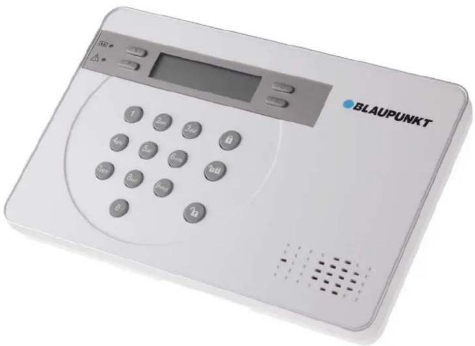
Table of Contents
- System Installation Planning 1
- Device Introduction 3
- First Time Setup 6
- Mount Devices 8
- System Default Setting 11
- User Menu 12
- Programming Mode 14
- Operation 22
- Connect2Home Application 26
- Troubleshooting & Factory Reset 27
- Specifications 29
Information and illustrations are subject to change within this document. Blaupunkt reserves the right to alter the specification and product design at anytime without notice.
Home and Away Arm Mode Planning
The alarm system supports two arming modes: Away Arm and Home Arm. Away Arm mode will arm all accessory devices installed in the system to raise alarm when activated; Home Arm mode will partial arm the system so that no intruder could get inside the premises without triggering an alarm, yet the user can move within the house freely. Plan your device location in advance by determine which area should remain unarmed in Home Arm mode, and decide which sensor should be set to deactivated in Home Arm mode.
For more information, please see 7. Programming Mode – Device +/- and 8. Operation.
Device Operating Range
All devices in the alarm system have an approximate range of 100 feet (33 yards) in typical domestic environment. The range may vary depending on different home condition. When installing devices, make sure to test the device range before actually mounting the device.
Tamper Protection
Your Control Panel and accessory devices are protected from sabotage attempt by a “tamper switch,” which is triggered when the device cover is opened, or removed from mounted surface. When the tamper switch is triggered, the alarm system will be activated to inform you. To make sure the tamper switch functions properly, please make sure the switch is fully depressed against the mounting surface when installing your Control Panel or devices.
System Extension
Aside from the devices included in the package, you can further improve the capability of your alarm system by purchasing extra accessories. Including extra PIR Sensor or Door Contract to extend your protection area; Remote Keypad for a secondary system operation platform; Smoke Detector for fire protection; Temperature Sensor for High/Low Temperature report; and Power Switch for energy management and Home Automation. Please check Blaupunkt website http://www.blaupunkt.com/us/products/home-security/ to learn more about accessory devices.
For more information, please see 7. Programming Mode – Device +/-
General Device Location Guideline:
- Avoid mounting the Control Panel and devices close to large metal objects or electrical interference source, such as fridge and microwave oven as they could affect signal strength.
- For devices that has tamper protection function, mount on even surface to ensure the tamper is fully closed when mounted. For uneven surface, use extra packing material on the back.
Device Location Panning:

PIR Sensor
● Mount the PIR sensor at 6.2-6.6 ft. height for best performance. When mounted at 6.6 ft. height, the PIR sensor has a range of 39 feet (13 yards).
● PIR sensor detection is most effective when the intruder is moving across its field of view. Do not mount PIR sensor in a location that faces intruder directly
- Do not mount the PIR sensor to look at door/window protect by Door Contact, as the signal transmitted simultaneously from PIR and Door Contact could cancel each other.
- Do not mount the PIR sensor directly exposed to sunlight,
- Do not point PIR sensor at window, or sources of heat e.g. fire or boiler.
Control Panel
● The Control Panel should be mounted in a hidden area and invisible, however still accessible.
● The Control Panel should be mounted at a location with good GSM strength to send report and receive command.
2. Device Introduction
The Alarm System supports multiple devices which are listed in this section. For accessory devices, please refer to individual device manual for detail instruction.
NOTE: The kit package you purchased includes the following devices:
1 x PIR Sensor, 1 x Door Contact, 1 Remote Controller
For other useful devices, see http://www.blaupunkt.com/us/products/home-security/
Control Panel
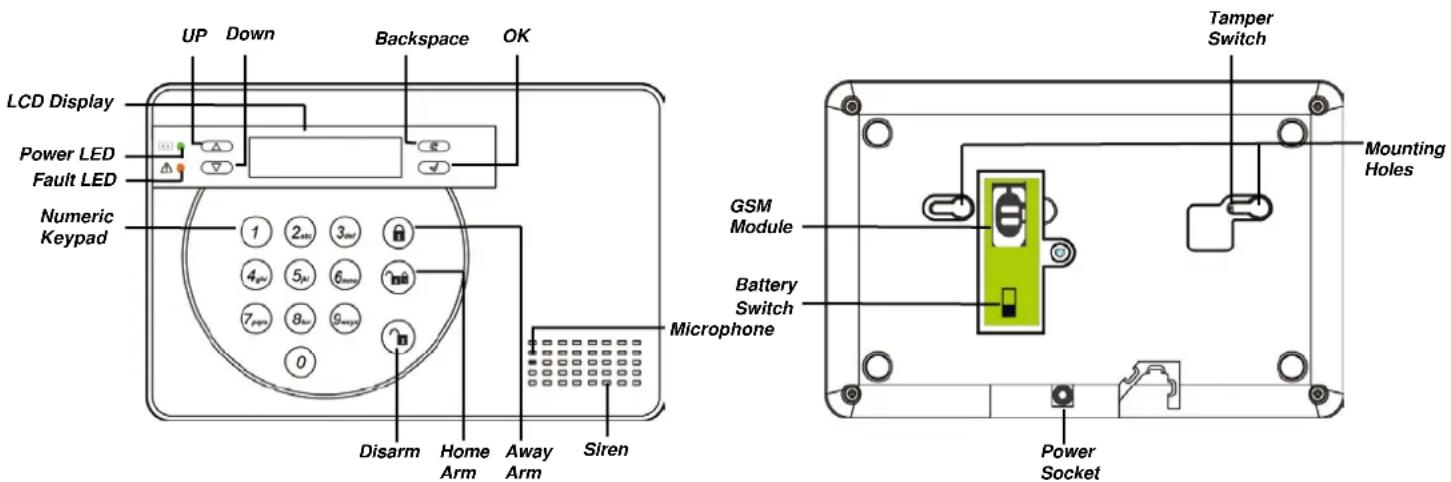
- A DC9V 1A adaptor is supplied to power the Control Panel. Do not plug in the adaptor at this stage yet, this will be done in the next section: First Time Setup.
- In addition to the adaptor, there is a rechargeable battery inside the Control Panel that serves as backup power in case of power failure. Once you have connected AC power supply, please turn on the battery switch to charge the battery. It take about 72 hours to fully charge the battery. When fully charged, the battery can serve as a back-up power source for about 18 hours.
IMPORTANT NOTE:
The Battery Switch is set to OFF by factory default. Please make sure to turn the switch to ON after connecting AC power to the Control Panel, otherwise the battery will not be charged and the Control Panel will be without back up power when power fails.
- The Control Panel requires a SIM card to send reports and receive commands. Before you insert the SIM card into GSM module, please note the following:
- The SIM card must be able to make and receive both telephone calls and SMS messages normally. Data only SIM cards are NOT compatible with the Control Panel.
- Please make sure SIM card PIN code is disabled. To check whether SIM Card PIN code is disabled, insert the SIM card into a working mobile phone, go to SIM card PIN code setting in mobile phone setting functions to disable the SIM card PIN code.
- If a prepaid SIM card is used, please check the SIM card information carefully as each SIM card provider has their own policy: Some SIM cards have a validity period and must be extended before they expires; some SIM cards will expire automatically if they are not used for a certain time period. When using prepaid SIM card, please make sure you fully understand its user policy, and check the SIM card's remaining value regularly with your service provider to make sure the SIM card is functioning normally.
PIR Sensor
● The PIR sensor detects movement and raise alarm when it detects an intruder.
● The PIR sensor is powered by 2 1.5V AA alkaline batteries pre-inserted by factory.
- Pull out the plastic battery saver tab on the back of PIR sensor, this will activate the batteries. The LED will flash for 30 seconds to indicated the PIR is warming up
- When the battery voltage runs low, please follow instruction below to change batteries:
- Remove the screw at bottom of PIR sensor to open the cover.
- Remove the old batteries and press the learn button a couple times to discharge.
- Insert the new batteries and replace the cover.

Door Contact:
● The Door Contact detects door/window opening and notifies the Control Panel to raise alarm.
● The Door Contact is powered by 2 1.5V AAA alkaline batteries pre-inserted by factory.
- Pull out the plastic battery saver tab on the back of Door Contact. This will activate the batteries..
- Press the learn button to transmit learn code.
- When the battery voltage runs low, please follow instruction below to change batteries:
- Remove the screw at bottom of Door Contact to open the cover.
- Remove the old batteries and press the learn button a couple times to discharge.
- Insert the new batteries and replace the cover.

Remote Controller
● You can arm, home, disarm, and activate an Emergency alarm with your Remote Controller
- For disarming action, you can only use Remote Controller to disarm the system after you have triggered an entry Door Contact or PIR sensor.
- The Remote Controller is powered by a CR2032 3V lithium coin cell which is included in the package.
- Open the back battery cover to insert the battery, then replace the cover.
- When the battery voltage runs low, slide open the battery cover to change new battery.


3. First Time Setup
This quick guide will take you through a step by step process of system initial setup.
NOTE: The First Time Setup process is only available when you power on the Control Panel for the first time. Once the process is completed, it will not appear again. All of the options can be changed later again, do not worry if you make any mistakes.
Detail system setting can be done later by accessing the Programming Mode.
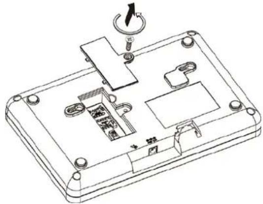
- Remove the screw on the GSM Module compartment cover, lift the cover. (Figure 1)
- Open the SIM Card base and insert SIM Card. Slide battery switch to ON position. (Figure 2)

- Connect the AC power to your Control Panel.
The Green Power LED will light up, The Control Panel LCD will display :
| 3 | s | t | e | p | s | e | a | s | y | ||||||
| s | e | t | u | p | ( | O | K | ? ) |
You now begin the First Time Setup Process.
NOTE: The sensor and accessory devices included in the package has already been included into the Control Panel. If you have purchased extra accessory devices, you can add them into the Control Panel by pressing the learn/test button on devices during First Time Setup Process. Refer to device manual for learn/test button location and detail.
1.
| 3 | s | t | e | p | s | e | a | s | y | ||||||
| s | e | t | u | p | ( | O | K | ? ) |
Press OK to continue.
2.
| S | e | t | D | a | t | e | / | T | i | m | e | ||||
| ( | O | K | ? | ) |
Press OK to continue, follow the on screen instruction to set date and time. Use Up and Down key to select the value and press OK to confirm.
3.
| S | e | t | 1 | p | h | o | n | e | n | u | m | ||||
| f | o | r | a | l | e | r | t | ( | O | K | ? | ) |
Press OK to continue, enter a telephone number you want to report event to, then press OK to confirm.
4.
| S | e | t | 1 | P | I | N | c | o | d | e | |||||
| ( | O | K | ? ) |
Press OK to continue, enter a 4-digit PIN code. Press OK to confirm.
5.
| E | x | i | t | S | e | t | u | p | |||||||
| R | e | p | e | a | t | S | e | t | u | p |
If you are satisfied with current setting, select Exit Setup and press OK to confirm.
If you want to make changes to current setting, select Repeat Setup and press OK to confirm. You will be returned to the beginning of the First Time Setup process.
NOTE: If no devices are included in the Control, Panel. When you choose Exit Setup, the LCD will display: Please add at least 1 device. You can either press the learn/test button on devices to add them, or press Disarm key, enter you PIN code, then press OK to exit the setup process.
6.
| M | o | u | n | t | D | e | v | i | c | e | s | ||||
| s | e | e | m | a | n | u | a | l |
First Time Setup process is now complete, please see next chapter for device mounting instruction.
This chapter will guide you through device mounting process.
After you complete First Time Setup process, if the Control Panel has already included accessory devices, the screen should display:
| M | o | u | n | t | D | e | v | i | c | e | s | ||||
| s | e | e | m | a | n | u | a | l |
Proceed to mount your sensors and accessory devices, tamper alarm will be disabled while the Control Panel remains under this screen for you to install devices without triggering tamper alarm.
Find the location where the devices are to be mounted, test device signal strength at the mounting location by putting the device at the location and pressing learn/test button on the device. Please refer to device manual for learn/test button location and detail.
If the device is within range of the Control Panel, the screen will display the device information accordingly. When you are certain the device can function properly at chosen location, proceed to mount the device.
When mounting devices, make sure the device tamper is fully depressed, please refer to device manual for tamper location.
Control Panel
The Control Panel tamper switch is located inside the mounting hole

- Use the holes on the mounting plate, mark the position of the holes on the wall at chest height. (Figures 1)
- Drill two holes into the wall, insert wall plug if required, (Figures 2) screw the mounting plate onto the wall at marked location. (Figures 3)
Figures 1

Figures 2

Figures 3

- Hook the Control Panel onto the plate, then slide the control panel left to secure the panel and depress the tamper switch against the mounting plate. (Figures 4)

PIR Sensor
The PIR Sensor has knockouts on the back where plastic is thinner. The 2 central knockouts are for flat wall mounting, and the four side knockouts are for corner mounting. (Figure 1)
- Break through the knockouts, use the knockouts to mark position on wall or corner. (Figure 2)
Figure 1

Figures 2

Corner
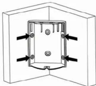
- Drill holes into the wall or corner using the knockouts as template, insert wall plug if required. (Figure 3)
- Screw the PIR Sensor base onto the wall or corner at marked location. (Figure 4) Then replace the PIR Sensor cover onto the base.
Figure 3

Figure 4
Door Contact
The Door Contact has two knockouts on the inside of the back cover where plastic is thinner for wall mounting. (Figure 1) The Door Contact should be mounted on the door/window frame, while the magnet should be mounted on the door/window.
-
Break through the knockouts; mark the mounting location on door/window frame using the knockout as template. (Figure 2)
-
Drill holes into the wall, insert wall plugs if required. (Figure 3)
Figure 1
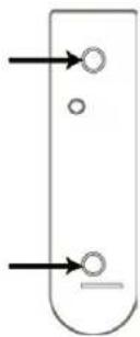
Figure 2

Figure 3

-
Screw the Door Contact back cover onto the wall at marked location, (Figure 4) replace the front cover.
-
The Door Contact has rib mark on the side that marks location of magnetic switch (Figure 5). Use the rib mark to align the magnet and screw the magnet on to the door/window (Figure 6). The distance between the magnet and Door Contact should be no more than 0.6 inch.
Figure 4

Figure 5

Figure 6
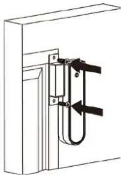
Alternatively, you can also use the double side adhesive tape to install the Door Contact.
After finish mounting your devices, the screen should still display:
| M | o | u | n | t | D | e | v | i | c | e | s | ||||
| s | e | e | m | a | n | u | a | l |
Press Disarm key, enter your PIN code, then press OK key. The screen will display Alarm Off along with current date and time.
The system is now in normal operation and under Disarm mode. For further system setting and operation, please see following chapters.
Entry/Exit Time and Device Attribute
When the system is armed and an Entry device is triggered, the Entry timer will begin to count down (default 20 seconds). The system must be disarmed before the timer expires, or a Burglar alarm will be activated.
When the system is being armed, the Exit timer will begin to count down (default 30 seconds), the system will ignore any sensors triggered during this period. The user should use this duration to leave the premises before the system is armed.
NOTE: The Entry Timer only works with device set to "Entry". PIR Sensor and Door Contact learned during the First Time Setup process will be assigned to "Entry" attribute. For device attribute detail and Entry/Exit Time programming, please see later chapter "Programming Mode."
Alarm Activation
When an alarm is triggered, the system will report to programmed telephone numbers according to their priority. Depend on your setting, the system will dial the telephone numbers you entered in the system and play voice message upon connection, or send an SMS message.
Address Message
The Address Message will be played in the beginning of all your voice message reports to notify the recipient your user information. Please make sure to record your own Address Message by referring to "Programming Mode." Default Address Message is "Alarm System."
Alarm Length
Default alarm length for siren upon activation is set to 3 minutes. To change the alarm length, please refer to "Programming Mode."
Jamming and Interference Detection
The Control Panel is capable of detecting radio signal jamming and interference, the function is disabled by default, if jamming and interference is of concern to you, please see chapter "Programming Mode"
The User Menu displays the system basic information and allows you to test system function
Entering User Menu
When the system is in Disarmed Mode (Alarm off), enter your User PIN Code to access User Menu.
Press a numeric key or G key, the display will prompt you to enter the PIN code:

Enter the complete PIN code and press OK within 30 seconds to enter User Menu.
The User Menu items include:
Fault Dsp – Fault event display
Log – System event log
Walk Test – Device range test
GSM Signal – GSM signal strength test
P-Mode – Programming Mode for system configuration
Use Up and Down key to scroll through the menu, press OK to select the function.
Fault Display
The system will automatically detect operational faults and records them under this section. Fault Dsp option will become available only when fault event exists in system, to view the fault events:
-
Use Up and Down key to scroll through the screen and view fault event:
-
Press G key to leave, you will be asked whether you want to clear fault display.
-
If you have rectified the fault, press OK to return to Alarm Off mode, and the fault event will be removed. (Unresolved fault event cannot be removed)
If you want to keep the fault event, press G to return to Alarm Off mode, the fault event will remain even if it has already been rectified.
Log
The Log memorizes the last 20 system events including
√ All Alarm Events with Device Information
√ All Fault Warning Events
√ All Arming And Disarming Events
● The logged events are displayed in reversed chronological order, (most recent event first).
- The log is marked with "Start" before the most recent entry and "End" after the oldest entry.
- To View Log, use UP and Down key to scroll through the screen and view log, the most recent event will be at the start
Walk Test
Walk Test allows you to test the signal range of sensor and accessory devices. To test the device
- Press the test or learn button on the device, refer to device user manual for detail.
- If the Control Panel receives the signal, the screen will display device type, zone number, attribute, name signal strength in 0\~9 scale accordingly. (Signal strength 9 being the strongest)
GSM Signal
Use GSM Signal function to check the Control Panel GSM signal strength at current location. The signal strength will be displayed in RSSI scale from 0\~9. In order for the Control Panel to send and receive report/command successfully, please make sure the RSSI value does not drop below 5 at installed location. If the value drops below 5, the Control Panel may not be able to send report and receive command successfully. You may consider relocating your Control Panel in this case.
Programming Mode
P-Mode allows the user to enter Programming Mode for detailed system setting, please refer to next chapter for detail.
To access the Programming Mode, you need to first enter the User Menu, and select P-Mode under User Menu. The screen will prompt you to enter the Master Code.
| P | - | M | o | d | e | E | n | t | e | r | |||||
| M | - | C | o | d | e | . | . | . | . |
Enter the Master Code within 30 seconds and press OK to enter Programming Mode. The system default Master Code is 1111.
The Programming Mode items include:
Walk Test – Device range test
Tel. Setting – Telephone number setting
Gen. Setting – General setting
Spc. Setting – Special setting
Device +/- - Add/Remove/Edit accessory device.
SMS Keyword – Edit SMS Keyword.
Reset GSM – Reset GSM module
Walk Test
The Walk Test function is identical to User Menu Walk Test option. It allows you to test the signal range of learned in device. To test the device:
-
Press the test or learn button on the device, refer to device user manual for detail.
-
If the Control Panel receives the signal, the screen will display device type, zone number, attribute, name signal strength in 0\~9 scale accordingly.
Tel. Setting
Tel. Setting is for you to set/edit telephone numbers for sending reports, and record Address Message. The following items can be selected:
Tel. Numbers
Record Msg.
Test report
Tel. Numbers
Use the function to set/change/delete the emergency telephone numbers.
A maximum of 6 telephone numbers can be stored. The numbers are listed from A to F in reporting priority, with A being the highest priority. Each number can store up to 20 digits. The telephone number entered during First Time Setup process will be assigned to priority A.
-
Select the telephone number you want to edit, press OK.
-
If the slot is empty, you will be asked to enter a new number.
If the slot already has a number stored, you will be asked to confirm if you want to change the number, press "OK" to confirm.
-
Enter the telephone number, press "OK" to confirm, if you want to delete existing telephone number, simply press "OK" without entering any number.
-
Select the report type for this telephone number, there are 2 choices:
Voice Report – The Control Panel will dial the telephone number and play pre-recorded voice message according to the event upon answer.
Telephone number set to Voice Report will be marked with "V" in the telephone number menu.
SMS Report – The Control Panel will send a SMS message to the telephone number to notify the user. For SMS report, you also need to select the event type to be reported with this telephone number:
√ All Event – All events will be reported
Telephone number set to All Events will be marked with "X" in the tel. number menu.
√ Alarm Event – Only alarm event will be reported
Telephone number set to Alarm Events will be marked with "A" in the tel. number menu.
√ Status Event – Only system status event will be reported.
Telephone number set to Status Events will be marked with "S" in the tel. number menu.
Record Msg.
Use the function to record your address message for Voice Report, the maximum length of the message is 10 seconds.
-
If no message was previously recorded, the display will show "Start Recording After the Beep" If you have already recorded a message, the display will ask you to confirm if you want to change the message, press "OK" to confirm.
-
After 2 seconds, the Control Panel will sound one beep, you can now start to record the message.
-
Speak clearly and slowly for the Control Panel to record your address. When you finish recording, press "OK" to stop recording, the recording will automatically stop when it reaches 10 second
NOTE: If you do not record your own Address Message, the system will play default alarm message when reporting. The default message is "Alarm System."
Test Report
This function allows you to test whether telephone function is working properly or not with the pre-set telephone numbers.
-
Your telephone numbers will be displayed, select the desired number and press "OK".
-
The Control Panel will dial the telephone number:
-
For Voice Report telephone numbers, upon successful connection, the Panel will play pre-recorded voice messages one by one for 85 seconds before hanging up. The messages include: Address Message/Emergency Message/Fire Message/Burglar Message/Medical Message.
The call recipient can end the call by pressing DTMF “#9” or hanging up the telephone. If the call recipient does not end the call, the Panel will hang up the telephone automatically after 85 seconds.
- For SMS Report telephone number, a SMS test report message will be sent.
General Setting
Program your system general setting under this menu. The items available include the following – see a) to g):
a) PIN Code
The PIN code is used to access the User Menu, and Arm/Home/Disarm the system. The system can store up to 4 User PIN Codes, each PIN code consists of 4 digits. When you Arm/Home/Disarm the system, the Control Panel will record the User PIN Code used to perform the action in system log for you to review. You can assign different User PIN Code to different family member so that the Control Panel can record the arming/disarming action of each user.
- User PIN code 1 is set during the First Time setup process.
- User PIN code 2\~4 are deactivated by factory default.
To set or change the PIN Code:
- Select the User PIN Code you want to edit, press "OK" to confirm.
- Enter the new User PIN Code in 4-digit number, press "OK" to confirm. If no number is entered, the User PIN Code will be deleted (User PIN Code 1 cannot be deleted.)
- Assign a user name to the new PIN Code, press "OK" to confirm.
- For entering user name with numeric keypad, please refer to the following table.
| 1 | 1 | |
| 2 | 2ABCabc | |
| 3 | 3 | DEFdef |
| 4 | 4 | GHIghi |
| 5 | 5 | JKLjkl |
| 6 | 6 | MNOmno |
| 7 | 7 | PQRSpqrs |
| 8 | 8 | TUVtuv |
| 9 | 9 | WXYZwxyz |
| 0 | 0/-&"."+: | |
| 5 | Deletecharacter and backspace | |
b) Master Code
The Master Code is used to access the Programming Mode for system setting.
● To change the Master Code, enter the new 4-digit code and press OK.
● Master Code factory default is set as 1111.
c) Entry Time
When a Door Contact (DC), PIR Detector (IR), or External PIR Detector (EIR) set to Entry attribute is triggered when the system is under Away Arm or Home Arm mode, the system will begin a countdown timer according to Entry Time setting. The system must be disarmed before the Entry Time expires, or an alarm will be activated.
- Options available are: Disable (alarm triggers immediately), 10 seconds, 20 seconds, up to 70 seconds in 10 second increments.
● 20 seconds is set as factory default.
d) Exit Time
When the system is being Away Armed or Home Armed, the system will begin a countdown timer according to the Entry Time setting. When the countdown timer expires, the system will enter the selected Arm Mode. The user must leave the premises before the timer expires.
- Options available are: Disable (exit timer prohibited), 10 seconds, 20 seconds up to 70 seconds in 10 second increments.
● 30 seconds is set as factory default.
e) Door Chime
This function allows you to decide whether the Control Panel should emit a two-tone Door Chime sound to notify the user when a Door Contact or PIR Detector set to Entry is triggered under Disarmed mode.
- Options available are : High, Low, Off
● Door Chime Off is set as factory default.
f) Time
This is for you to program the current time to be displayed. (Hour & minute)
- Use Up and Down keys to select the Hour and Minute, and press OK to confirm.
g) Date
This is for you to set the current date.
- Use Up and Down keys to select the Month and Day, and press OK to confirm
h) Panel Siren
This is for you turn on/off the Control Panel's built-in siren. When turned off, the Control Panel will not sound any warning when an alarm is activated.
● Siren On is set as factory default.
Special Setting
Special setting provides more function for detail system configuration. The items available include the following – see a) to h):
a) Alarm Length
This is for you to select the time length siren should sound when an alarm is activated.
- Options available are: 1\~15 minute in 1-minute increment.
● 3 minutes is set as factory default.
b) Exit Sound
This is for you to decide whether the Control Panel should sound count-down beeps and volume of beep during Entry Time
- Options available are: High, Low, Off
- Exit Sound Lo (Exit sound Low) is set as factory default.
c) Entry Sound
This is for you to decide whether the Control Panel should sound count-down beeps and volume of beep during the Entry Time.
- Options available are: High, Low, Off
● Entry Sound Lo (Entry sound Low) is set as factory default.
d) Interference
This is for you to turn on and off the interference detection feature. When interference detection is turned On, if RF signal jamming is detected continuously for 30 seconds, the fault event will be
logged, reported to programmed telephone number and displayed on the LCD to warn the user.
● Detection Off is set as factory default.
e) Final Door
If set to On, when the system is being Away Armed and a Door Contact set to Entry attribute is closed before the Exit Delay timer expires, the system will enter Away Arm mode immediately even if the Exit Delay timer has not expired yet. If set to Off, the system will only enter Away Arm mode after the Exit Delay Timer has expired.
● Final Door Off is set as factory default.
f) Siren Tamper
This function is only used for optional external sirens. If the Control Panel has included external siren in the system, their tamper switches can be enabled and disabled remotely.
● Siren Tamper On is set as factory default.
- When the Siren Tamper is turned off, it will automatically revert to On after about an hour if not switched back.
NOTE: For other devices, the tamper function will be disabled when the Control Panel is under Programming Mode.
g) H. Temperature (Optional Temperature Sensor Required)
The Control Panel features High and Low Temperature report function which requires a Temperature Sensor to use.
The H. Temperature option is for you to set the High Temperature Threshold. When the temperature exceeds this threshold by 1° C, a SMS report will be sent to programmed telephone number.
- You can set the temperature within the range of -10°C to +50°C
- When entering temperature value, press Up key to select negative value. Down key to select positive value.
- When the temperature drops to 3°C below the threshold, a SMS report will be sent to programmed telephone number to notify the recipient of High Temperature Restoration.
- You can set a High Temperature Threshold and choose to enable or disable the reporting function. If reporting is disabled, the system will not send out report when the temperature exceeds the threshold, but a log event will still be recorded in system
● High Temperature Warning is Disabled by factory default
h) L. Temperature (Optional Temperature Sensor Required)
The system will send Low Temperature SMS reports when temperature drops to 1° C below the Low Temperature Threshold.
- When the temperature returns to 3°C above the threshold, a SMS report will be sent to programmed telephone number to notify the recipient of Low Temperature Restoration.
● Low Temperature setting format is the same as High Temperature setting.
● Low Temperature Threshold must be at least 4° C lower than High Temperature Threshold.
● Low Temperature Warning is Disabled by factory default.
Device +/-
Devices +/- allows you to add/remove /edit devices. The functions include:
Add Devices
Edit Devices
Remove Devices
Learn PSS
Add Devices
- To learn in a device, select Add Device, press "OK" to confirm.
- Press the test /learn button on the device, refer to device manual for detail.
-
If a signal is detected, the screen will display the device information, press "OK" to confirm.
If the device already exists in system, the screen will display "Already exist in system": -
Select the Zone number for the device, press "OK" to confirm.
-
For Door Contact, PIR sensor, and EIR sensor, you need to select one of the three attributes for the device, available attributes include:
- Burglar (B)
When the device is triggered under Away Arm or Home Arm mode, a Burglar Alarm will be activated immediately.
When the device is triggered during Entry or Exit countdown, the alarm will not be activated.
● Home Omit (O)
When the device is triggered under Away Arm mode, a Burglar Alarm will be activated immediately.
When the device is triggered under Home Arm mode, the alarm will not be activated.
- Entry (E)
When the system is in any Arm mode, if an "Entry" device is triggered, the Control Panel will start an Entry Delay countdown timer for the user to disarm the system.
After the delay period has expired and no correct PIN code has been entered, the Control Panel will activate iren immediately to remind the user the delay period has expired.
If the Control Panel is not disarmed within 30 seconds after the delay period expires, a Burglar Alarm will be reported. Disarming the Control Panel within the 30 second period will return the system to Disarm mode and silence the siren. No alarm will be reported.
When the system is in Disarm mode, if a “Entry” is triggered, the Control Panel will make a “ding-dong” Door Chime sound (if Door Chime function is not disabled).
-
Enter a name for the device, press "OK" to confirm. You can also leave the name blank.
-
The screen will display the final device information, press "OK" to confirm and complete learning for the device
The device types are identified by the following abbreviation in the system:
√ Door Contact ---- DC
√ PIR Sensor ---- IR
√ Remote Controller --- RC
√ Remote Keypad ---KP
√ Smoke Detector --- SD
√ Temperature Sensor --- TS
√ Outdoor Siren --- BX
Edit Devices
Use Edit Device to change setting for learned in devices. The screen will display available devices.
- Select the device you want to edit, press "OK" to confirm.
- Edit the device information according to the setting in Add Device.
Remove Devices
This function is used to remove an existing device from the system.
- Select the device you want to remove, press "OK" to confirm.
- You will be asked to confirm your action, press "OK" to confirm.
- The device will be removed from the system.
Learn PSS (Optional Power Switch Required)
This function is used to learn in Power Switch (PSS) only.
- Put the Power Switch into Learning Mode; refer to Power Switch manual for detail.
- Select the Power Switch Channel # you desire, press "OK" to confirm.
- Select the device you want to edit, press "OK" to confirm, the Control Panel will transmit signal to Power Switch.
- The Power Switch LED will flash 3 times upon receiving signal from Control Panel, the learning is now complete
Learn RP (Optional Repeater Required)
This function is used to learn in Repeater only.
- Put the Repeater into Learning Mode; refer to Power Switch manual for detail.
- Select "Learn RP" and press "OK" to confirm. The Control Panel will transmit signal to Repeater.
- The Repeater LED will light up if learning is successful.
SMS Keyword
The SMS Keyword is required if you want to remotely control the alarm system. When you send a SMS command to the Control Panel, the correct SMS Keyword must be entered in the SMS message for the Control Panel to recognize the command.
IMPORTANT NOTE: The SMS Keyword is capital letter sensitive. Please take care to note down whether your SMS Keyword is entered in upper case or lower case
Reset GSM
Reset GSM function allows you to reset your GSM module. You can reset the GSM if the Panel has GSM related fault conditions to try to solve the problem.
- When you select the function, the screen will display "Please wait". Do not touch the Control Panel during the GSM reset process
- When GSM reset is complete, the screen will return to Programming Mode
This chapter covers system general characteristic under normal operation.
Away Arm
Away Arm will arm all devices in the system
Arming the System
When the system is under Disarm mode:
- Press the "Arm" key on the Control Panel, Remote Controller, or Remote Keypad.
- The Exit Timer will be displayed and begin to count down according to system setting.
- When the Exit Time is up, the Control Panel will sound a long beep. Alarm On will be displayed on the screen and the system enters Away Arm Mode.
Stopping the Exit Timer
- Press the "Disarm" key on the Control Panel and enter a User PIN Code; press the "Disarm" key on Remote Controller; or enter a User PIN Code and press the Disarm key on Remote Keypad.
- The Exit Timer will stop and the system returns to Disarm mode.
Extending the Exit Timer
- Press the "Arm" key on the Remote Controller and Remote Keypad again.
- The Exit Timer will be reset and start counting from the beginning.
Home Arm
Home Arm will partially arm the system and allows free movement inside the house.
Arming the System in Home Mode
When the system is under Disarm mode:
- Press the "Home" key on the Control Panel, or Remote Controller, Remote Keypad.
- The Exit Timer will be displayed and begin to count down according to system setting.
- When the Exit Time is up, the Control Panel will sound three short beeps. Home will be displayed on the screen and the system enters Home Arm Mode.
Stopping the Exit Timer
The Exit Timer can be stopped in the same way as Away Arm mode..
Extending the Exit Timer
- Press the "Home" key on the Remote Controller and Remote Keypad again.
- The Exit Timer will be reset and start counting from the beginning.
NOTE: The Remote Keypad has the option to choose between "Arm without User PIN Code", or "Arm with User PIN Code". When the keypad is set to "Arm with User PIN Code", you need to enter the PIN Code then press Armor Home key to arm the system. Please refer to Remote Keypad manual for more detail.
Force Arm
When you arm the system, if any fault event exists, the Control Panel will sound a ding-dong warning sound to indicate arming is prohibited, the fault event will be displayed on screen.
At this moment, you can first rectify all of the problems and then clear the Fault Display and you will be able to arm the system normally.
If you want to Away/Home Arm the system without solving the fault event. Follow steps below to Forced Arm.
- Press ARM / HOME button on the Control Panel again, you will be ask to confirm Force Arm action, press OK to double confirm.
For Remote Controller, Remote Keypad, press ARM / HOME button again.
- The Exit Delay timer will begin to count down.
- When the Exit Delay time is up, the Control Panel will enter the arm mode you selected.
Disarm
When the system is under Away Arm or Home Arm mode, to disarm the system:
- For Control Panel, press the "Disarm" key and enter a User PIN Code, then press OK.
- For Remote Keypad, enter a User PIN Code and press the "Disarm" key.
- For Remote Controller, press "Disarm" key.
Alarm Activation
- When a device set to Burglar is triggered, the alarm will be activated immediately.
- When a device set to Entry is triggered, the Entry countdown timer will be activated. If the system is not disarmed before the timer expires, an alarm will be activated.
- When a device set to Home Omit is triggered in Home Arm mode, the device will be ignored. If the device is triggered in Away Arm mode, the alarm will be activated immediately
- When the tamper switch of the Control Panel or devices is triggered in Away Arm mode, the alarm will be activated immediately.
● You can trigger an Emergency alarm with the Remote Controller
- You can trigger an Emergency/Fire/Medical alarm with the Remote Keypad. Please refer to Remote Keypad manual
● You can trigger an Emergency/Fire/Medical alarm with Control Panel keypad:
Press and hold both "1" and "3" key to trigger an Emergency Alarm.
Press and hold both "4" and "6" key to trigger a Fire Alarm.
Press and hold both "1" and "3" key to trigger a Medical Alarm.
Stopping the Alarm and Alarm Display
During an alarm, the Control Panel will sound the siren, and report to programmed telephone number. The screen will display "ALARM! ALARM!" to notify the user
Stopping the Alarm
● Enter a User PIN Code and press OK key on the Control Panel.
● Enter a User PIN Code and press Disarm key on the Remote Keypad.
- Press Disarm key on the Remote Controller
- The alarm will be stopped; the device that triggered the alarm will be displayed on screen. Use the Down button to scroll down the alarm event, the screen will display whether the system reported successfully to programmed telephone number or not.
- When you finish viewing the alarm event, the system will enter Disarm mode.
NOTE:
- Remote Controller cannot be used to stop the Emergency Alarm triggered by itself.
- If you disarm the system with Remote Controller, the Control Panel screen will continue to display "ALARM!ALARM!" message to remind you to check the alarm memory.
Alarm Memory
If an alarm was raised without being silenced during your absence, and the alarm reporting has been carried out; the screen will continuously show “ALARM! ALARM!” to warn the user.
- When you come back and disarm the system, the siren will sound for 3-second to warn you that the intruder might still be inside your house.
- View the alarm event by scrolling down with Down key, when you finish viewing the alarm event, the system will enter Disarm mode.
Tamper Protection
- When the system is under Away mode, if a tamper switch is triggered, an alarm will be activated immediately. The Control Panel will send a SMS alarm event “Tamper” to programmed SMS report telephone number, or dial the Voice report telephone number and play “Burglar” message upon answer.
- When the system is under Home or Disarm mode, if a tamper switch is triggered, the Control Panel will not make any report or activate alarm. The fault LED will light up and a fault event will be registered in the Control Panel.
Dialling and Call Acknowledgement
When an alarm is activated, the Control Panel will dial the programmed telephone numbers in priority order for Voice Message or SMS Message report. When the Control Panel makes Voice Message Reports:
- After dialling, the Control Panel will delay 5 seconds then starts to play the message. It will first play the general part of the recorded message (Address) then plays the specific alarm message (Burglar, Fire, Medical or Emergency) depending on the nature of the alarm.
- To ensure the call is successfully received by the recipient, the recipient should acknowledge the message by pressing the appropriate button on his telephone set.
-
If the Control Panel does not receive any acknowledgement, the message will be repeated for 85 seconds. The Control Panel will then consider the call unsuccessful and dial the next phone number in priority.
-
If more than one number is programmed the Control Panel will continue to dial the number(s) until a recipient presses the third response key.
- If no phone number is programmed, the Control Panel will not dial.
Call Acknowledgement
When the Control Panel makes Voice Report, there are 3 responses available for the recipient to receive the call, by pressing 1, 0 or 9 key on his telephone set.
Press 1:
√ The Control Panel will open a one-way listen only channel for 2 minutes for you to listen to what is happening on the other side.
√ During the last 20 seconds of the 2-minute period, the Control Panel will sound a beep to remind the recipient. Press 1 again to extend another 2 minutes.
√ When the 2-minute period expires, the Control Panel will automatically hang up and dial the next number.
Press 0:
√ The Control Panel will hang up.
√ The Control Panel will continue Alarming.
√ The Control Panel will dial the next number.
Press 9:
√ The Control Panel will hang up.
√ The Control Panel will stop alarming and stop dialling.
The panel will also stop reporting if 2 call recipients pressed 1 or 0 to acknowledge the report
If the call recipient hangs up the telephone without any acknowledgement, the Control Panel will redial the telephone to retry the report for a maximum of 5 times.
Auto Redial
- When only one telephone number is stored and the number is engaged, the Control Panel will automatically redial up to 5 times with an interval of 80 sec. between each attempt.
- When more than one telephone numbers are stored, the Control Panel will dial according to priority order. If the number being dialled is engaged, it will try the next number. Each number will be tried up to 5 times and the interval between each attempt is 20 sec.
● The Control Panel will redial the telephone numbers for up to 3 cycles, 15 times maximum.
What is "Connect2Home" application?
The Connect2Home application is a free smart phone application designed to help you remotely operate and program your alarm system by sending SMS commands. It has a clean and intuitive interface for easy recognition and operation. Furthermore, the Connect2Home application features extra Home Automation setting which allows you to control your home appliances automatically if you have included Power Switches in your alarm system.
How do I get the "Connect2Home" application?
The Connect2Home application is available in both Android phone and iPhone version. You can download the app for free by searching "Connect2Home" in Google Play or Apple App Store. The application is only compatible with iPhone and Android phone; it does not support iPad or Android tablet computer
For iPhone user, iOS 6.1 or higher version is required
For Android user, Android 2.2 or higher version is required.
How do I use the "Connect2Home" application?
Once you have downloaded and installed the app on your smartphone, please visit Blaupunkt website www.blaupunkt.com to download the user guide for Connect2Home application.
NOTE: The Connect2Home application functions by sending SMS commands to your Control Panel. Please be reminded that each SMS command will incur extra cost.
This chapter covers the potential issues you may encounter during system operation, and factory reset function
Control Panel
Control Panel Fault Orange LED indicates fault in system, When the LED light up, please enter User Menu and select Fault Dsp to view fault events. The possible fault events include:
● Control Panel / Devices low battery:
-- Change device batteries or charge Control Panel battery accordingly.
- AC power fail:
-- Check AC power connection
● Sensor out of order:
-- Check device battery status and conduct Walk Test to confirm if the Control Panel can receive device signal.
● Control Panel / Device tamper:
-- Close the Control Panel or device's tamper switch.
● GSM related failures:
-- Check if SIM card is properly installed
-- Enter User Menu and select GSM signal to check GSM network coverage. If GSM signal is unsatisfactory, consider changing Control Panel location or try different GSM service provider.
-- Enter Programming Mode and select Reset GSM to reset GSM module.
- Interference:
-- Perform Walk Test on all your devices to check if Control Panel can still receive their signals.
-- Use Test Call function to test if Control Panel can report normally to programmed telephone number.
PIR Sensor
● PIR LED flashes when activated:
-- PIR is on low battery or tamper switch triggered.
● PIR does not respond to movement:
-- PIR has a built-in 1 minute sleep timer after detecting a movement. PIR will not redetect movement within 1 minute after it is triggered. Please wait for at least 1 minute before testing PIR again.
-- Battery exhausted, please change battery.
- PIR is slow to respond:
-- This is normal. PIR has sophisticated false arm filter setting to prevent accidental trigger. It is also less sensitive when walking directly toward it:
- PIR give false alarm:
-- Make sure pets have no access to protected area.
-- Make sure the PIR is not pointed at source of heat or moving objects
● PIR is slow to respond:
-- This is normal. PIR has sophisticated false arm filter setting to prevent accidental trigger. It is also less sensitive when walking directly toward it:
- PIR give false alarm:
-- Make sure pets have no access to protected area.
-- Make sure the PIR is not pointed at source of heat or moving objects
Door Contact
● Door Contact LED flashes when activated:
-- Door Contact is on low battery or tamper switch triggered.
● Door Contact does not respond to door/window opening
-- Batteries exhausted, please change battery.
-- The magnet is too far away from the Door Contact, please check the gap between the magnet and the Door Contact. Reduce the gap and test the Door Contact again.
Remote Controller
● Remote Controller LED glows dimly when any key is pressed
-- Remote Controller on low battery.
Factory Reset
The Factory Reset function will delete all learned in devices and returns all system setting to default value. After the setting you will need to setup the system again from the beginning via First Time Setup.
-
Power down Control Panel by disconnecting AC Power and switching off battery switch.
-
Apply AC Power while holding down the ▲ key.
-
Release the ▲ key when you hear a beep, the screen will display Enter Code.
-
Enter the following keys sequence: ▲▼▲▼▲▼▲▼, OK
-
Press the G key
-
Reset is complete and all programmed parameters are reset to factory default setting. All devices are removed and must be learnt in again.
All Devices
Environmental Condition
-10°C to 40°C, relative humidity 85% non-condensing for Control Panel and all devices.
Radio Operation Range
About 30m in typical domestic installation, range can vary depending on building construction, device location, and environment.
Control Panel
Display
2x16 character LCD
Keypad
17 keys keypad
Siren Output
96 dBA sound pressure @ 1m minimum
Zones
30 radio devices (Plus 4 optional Power Switches).
Power Supply
DC9V 1A Power Adaptor
Battery
4.8V 600mAh Ni-MH Rechargeable Battery, charge time 72 hours.
Battery Backup Time
18 hours
PIR Sensor
Radio Frequency
433MHz
Battery
2 x 1.5V AA alkaline batteries
Door Contact
Radio Frequency
433MHz
Battery
2 x 1.5V AAA alkaline batteries
Remote Controller
Radio Frequency
433MHz
Battery
1 x CR2032 3V lithium coin cell
Compliance Statement
Declaration of Conformity
This device complies with the requirements of the R&TTE Directive 1999/5/EC and the following harmonized standards have been applied:
Health: EN50385:2002
Safety: EN60950-1:2006+A11:2009+A1:2010+A12:2011
EMC: EN 301 489-1 V1.9.2:2011-09, EN 301 489-3 V1.4.1:2002-08
EN 301 489-7 V1.3.1:2005-11
Radio: 3GPP TS 51.010-1 V9.8.0, EN 301 511 V9.0.2 (GSM 13.11)
3GPP TS 51.010-1 V9.8.0, 3GPP TS 51.010-2 V9.0.1
3GPP TS 51.010-4 V4.14.1, 3GPP TS 51.010-5 V9.0.1
EN 300 220-2 V2.4.1:2012:05
FCC
FCC Statement
This device complies with Part 15 of the FCC Rules. Operation is subject to the following two conditions:
(1) This device may not cause harmful interference, and
(2) This device must accept any interference received, including interference that may cause undesired operation.
FCC Caution:
To assure continued compliance, any changes or modifications not expressly approved by the party responsible for compliance may void the user's authority to operate this equipment. (Example - use only shielded interface cables when connecting to computer or peripheral devices).
Blaupunkt Competence Center Security & Care
Azure Security & Care Corporation
www.blaupunkt.com
6F., No.1, Lane 250, Sinhu 2nd Rd.,
Neihu, Taipei 114, Taiwan




- SA 2700 KIT USER MANUAL
- TABLE OF CONTENTS
- HOME AND AWAY ARM MODE PLANNING
- DEVICE OPERATING RANGE
- TAMPER PROTECTION
- SYSTEM EXTENSION
- GENERAL DEVICE LOCATION GUIDELINE
- DEVICE LOCATION PANNING
- PIR SENSOR
- CONTROL PANEL
- DEVICE INTRODUCTION
- IMPORTANT NOTE
- DOOR CONTACT
- REMOTE CONTROLLER
- FIRST TIME SETUP
- ENTRY/EXIT TIME AND DEVICE ATTRIBUTE
- ALARM ACTIVATION
- ADDRESS MESSAGE
- ALARM LENGTH
- JAMMING AND INTERFERENCE DETECTION
- ENTERING USER MENU
- FAULT DISPLAY
- LOG
- WALK TEST
- GSM SIGNAL
- PROGRAMMING MODE
- TEL. SETTING
- TEL. NUMBERS
- RECORD MSG
- TEST REPORT
- GENERAL SETTING
- PIN CODE
- MASTER CODE
- ENTRY TIME
- EXIT TIME
- DOOR CHIME
- TIME
- DATE
- PANEL SIREN
- SPECIAL SETTING
- EXIT SOUND
- ENTRY SOUND
- INTERFERENCE
- FINAL DOOR
- SIREN TAMPER
- TEMPERATURE (OPTIONAL TEMPERATURE SENSOR REQUIRED)
- DEVICE
- ADD DEVICES
- EDIT DEVICES
- REMOVE DEVICES
- LEARN PSS
- LEARN PSS (OPTIONAL POWER SWITCH REQUIRED)
- LEARN RP (OPTIONAL REPEATER REQUIRED)
- SMS KEYWORD
- RESET GSM
- AWAY ARM
- ARMING THE SYSTEM
- STOPPING THE EXIT TIMER
- EXTENDING THE EXIT TIMER
- HOME ARM
- FORCE ARM
- DISARM
- STOPPING THE ALARM AND ALARM DISPLAY
- STOPPING THE ALARM
- NOTE
- ALARM MEMORY
- DIALLING AND CALL ACKNOWLEDGEMENT
- CALL ACKNOWLEDGEMENT
- PRESS 1
- PRESS 0
- PRESS 9
- AUTO REDIAL
- WHAT IS "CONNECT2HOME" APPLICATION
- HOW DO I GET THE "CONNECT2HOME" APPLICATION
- HOW DO I USE THE "CONNECT2HOME" APPLICATION
- FACTORY RESET
- ALL DEVICES
- ENVIRONMENTAL CONDITION
- RADIO OPERATION RANGE
- DISPLAY
- KEYPAD
- SIREN OUTPUT
- ZONES
- POWER SUPPLY
- BATTERY
- BATTERY BACKUP TIME
- RADIO FREQUENCY
- COMPLIANCE STATEMENT
- DECLARATION OF CONFORMITY
- FCC
- FCC STATEMENT
- FCC CAUTION
Brand : BLAUPUNKT
Model : SA 2700
Category : Surveillance Camera