
ISP40 - Media player Audac - Free user manual and instructions
Find the device manual for free ISP40 Audac in PDF.


| Product Type | Media Player |
| Brand | Audac |
| Model | ISP40 |
| Dimensions (approx.) | 120 x 80 x 20 mm |
| Weight (approx.) | 200 g |
| Power Supply | 5V DC via USB port |
| Supported Media Formats | MP3, WMA, WAV, MPEG-4, AVI, JPEG |
| Storage Expansion | MicroSD card slot up to 32 GB |
| USB Port | USB 2.0 for flash drives |
| Audio Output | 3.5 mm headphone jack |
| Video Output | HDMI (optional cable required) |
| Main Functions | Play music, videos, view photos, FM radio, text reading |
| Display | 2.4 inch TFT color screen (320x240) |
| Battery | Built-in rechargeable Li-ion, 3.7V 800mAh |
| Charging Time | Approximately 2-3 hours via USB |
| Playback Time | Up to 6 hours music, 4 hours video |
| Operating System | Proprietary embedded system |
| Languages | Multi-language menu (English, French, Spanish, etc.) |
| Maintenance | Wipe with dry soft cloth; do not use solvents |
| Safety Precautions | Keep away from water, heat, and magnetic fields |
| Spare Parts & Reparability | No user-serviceable parts; contact authorized service center |
| General Information | Designed for personal entertainment; compatible with Windows/Mac for file transfer |
Frequently Asked Questions - ISP40 Audac
User questions about ISP40 Audac
0 question about this device. Answer the ones you know or ask your own.
Ask a new question about this device
Download the instructions for your Media player in PDF format for free! Find your manual ISP40 - Audac and take your electronic device back in hand. On this page are published all the documents necessary for the use of your device. ISP40 by Audac.
USER MANUAL ISP40 Audac
This manual is put together with much care, and is as complete as could be on the publication date. However, updates on the specifications, functionality or software may have occurred since publication. To obtain the latest version of both manual and software, please visit the Audac website @ www.audac.eu.
Index
Introduction 5
Precautions 6
Safety requirements 6
Caution servicing 6
EC Declaration of Conformity 6
Waste of Electrical and Electronic Equipment (WEEE) 7
Caution 7
Chapter 1: Pin connections and connectors 9
Connection standards 9
Chapter 2: Front & rear panel 10
Front panel overview 10
Front panel description 10
Rear panel overview 11
Rear panel description 11
Chapter 3: Using the ISP40 12
Database updates 13
Main screen 13
Station selection 13
ISP40 settings 14
General settings 16
Chapter 4: Additional information 17
IP Basics 17
Technical specifications 18
Notes 19
Introduction
Professional internet audio player
The ISP40 is a professional internet radio player featuring the unique Linum ^™ technology which eliminates any unwanted behaviour such as sudden channel hopping or music stops. An internal buffer will avoid any music interruptions for short term connection interruptions and will make sure the audio stream will be automatically restored afterwards.
The front panel of the system accommodates a 2.8" TFT display in combination with a push rotary function dial and 4 tactile pushbuttons. The controls and indicators on the front panel of the unit are guaranteeing an intuitive and user friendly operation, allowing hassle free operation and configuration to even unexperienced users. Information such as internet radio station information is are indicated.
It synchronizes with the database which contains over 30.000 channels, allowing selection on different criteria such as genre, location, language, ... while custom streams can also be added to a preference list up to 100 entries. The signal output level as well as the systems IP settings and other advanced network settings are user configurable, allowing implementation to any audio system connected to home, office or enterprise data networks.
The input connection is implemented by an RJ45 type connector with indicator LED's, allowing connection to any ethernet network. The balanced stereo line output is connected through two 3-pin terminal block connections.
The RS-232 communication port allows system integration with any home or industrial automation system, while an optional 2.4 GHz remote control allows handheld control while hidden out of sight.
Precautions
READ FOLLOWING INSTRUCTIONS FOR YOUR OWN SAFETY
ALWAYS KEEP THESE INSTRUCTIONS. NEVER THROW THEM AWAY
ALWAYS HANDLE THIS UNIT WITH CARE
HEED ALL WARNINGS
FOLLOW ALL INSTRUCTIONS
NEVER EXPOSE THIS EQUIPMENT TO RAIN, MOISTURE, ANY DRIPPING OR SPLASHING LIQUID. AND NEVER PLACE AN OBJECT FILLED WITH LIQUID ON TOP OF THIS DEVICE.
DO NOT PLACE THIS UNIT IN AN ENCLOSED ENVIRONMENT SUCH AS A BOOKSHELF OR CLOSET. ENSURE THERE IS ADEQUATE VENTILATION TO COOL THE UNIT. DO NOT BLOCK THE VENTILATION OPENINGS.
DO NOT STICK ANY OBJECTS THROUGH THE VENTILATION OPENINGS.
DO NOT INSTALL THIS UNIT NEAR ANY HEAT SOURCES SUCH AS RADIATORS OR OTHER APPARATUS THAT PRODUCE HEAT
DO NOT PLACE THIS UNIT IN ENVIRONMENTS WHICH CONTAIN HIGH LEVELS OF DUST, HEAT, MOISTURE OR VIBRATION
THIS UNIT IS DEVELOPED FOR INDOOR USE ONLY. DO NOT USE IT OUTDOORS
PLACE THE UNIT ON A STABLE BASE OR MOUNT IT IN A STABLE RACK
ONLY USE ATTACHMENTS & ACCESSORIES SPECIFIED BY THE MANUFACTURER
UNPLUG THIS APPARATUS DURING LIGHTNING STORMS OR WHEN UNUSED FOR LONG PERIODS OF TIME
ONLY CONNECT THIS UNIT TO A MAINS SOCKET OUTLET WITH PROTECTIVE EARTHING CONNECTION
THE MAINS PLUG OR APPLIANCE COUPLER IS USED AS THE DISCONNECT DEVICE, SO THE DISCONNECT DEVICE SHALL BE READILY OPERABLE

CAUTION - SERVICING
This product contains no user serviceable parts. Refer all servicing to qualified service personnel. Do not perform any servicing (unless you are qualified to)

EC DECLARATION OF CONFORMITY
This product conforms to all the essential requirements and further relevant specifications described in following directives: 2014/30/EU (EMC) and 2014/35/EU (LVD)
WASTE ELECTRICAL AND ELECTRONIC EQUIPMENT (WEEE)
The WEEE marking indicates that this product should not be disposed with regular household waste at the end of its life cycle. This regulation is created to prevent any possible harm to the environment or human health.

This product is developed and manufactured with high quality materials and components which can be recycled and/or reused. Please dispose this product at your local collection point or recycling centre for electrical and electronic waste. This will make sure that it will be recycled on an environmentally friendly manner, and will help to protect the environment in which we all live.
CAUTION
The symbols shown are internationally recognized symbols that warn about potential hazards of electrical products. The lightning flash with arrowpoint in an equilateral triangle means that the unit contains dangerous voltages. The exclamation point in an equilateral triangle indicates that it is necessary for the user to refer to the users manual.

These symbols warn that there are no user serviceable parts inside the unit. Do not open the unit. Do not attempt to service the unit yourself. Refer all servicing to qualified personnel. Opening the chassis for any reason will void the manufacturer's warranty. Do not get the unit wet. If liquid is spilled on the unit, shut it off immediately and take it to a dealer for service. Disconnect the unit during storms to prevent damage.
Chapter 1
Pin connections and connectors
CONNECTION STANDARDS
The in- and output connections for AUDAC audio equipment are performed corresponding to international wiring standards for professional audio equipment.
3-Pin Terminal Block:
For balanced in & output connections

Left: Signal - (XLR Pin 3)
Center: Signal + (XLR Pin 2)
Right: Ground (XLR Pin 1)
For balanced line output connections:
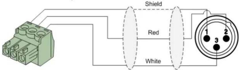
For unbalanced line output connections:

RS232 (serial connection interface):
For connection with home automation systems, or other remote control equipment
Connection
| PIN | 2 |
| PIN | 3 |
| PIN | 5 |
Standard RS232
| 8 | Bit | |
| 1 | Stop | bit |
| No | parity | |
| No Handshaking | ||
Settings 19200 Baud
RS232
The complete command set for controlling the ISP40 through RS-232 is available in the ISP40 commands user manual which is freely downloadable on www.audac.eu
Chapter 2
Front & rear panel
Front Panel overview

Front panel description
Graphical LCD display with tactile push buttons and rotary selection dial:
A clear system overview and intuitive user experience is offered using the 2.8" graphical LCD display accompanied with four tactile selection buttons (left side) and a rotary selection dial (right side). The true colour display offers a clear overview of the systems current operation mode with intuitive and user friendly browsing through the menu structure.
The functionality of the four tactile push buttons on the left side depends on the current mode and position in the menu structure. Icons on the left side of the display are indicating the current functionality linked with the buttons.
Parameter adjustment and browsing is made easy using the rotary function dial. This multifunctional dial allows easy one-hand operation throughout the entire menu structure. Browsing through the menu is done by rotating it while actions are made by pressing it.
Power switch:
Allows to power the system ON and OFF. The blue indicator LED illuminates when switched on.
Rear Panel overview

natural_image
Back view of a black server rack with ports, connectors, and network switches (no visible text or labels)Rear panel description
AC Power inlet with fuse:
The mains power supply (100–240V AC – 50/60 Hz) has to be applied to this AC power inlet. The connection is made by an IEC C14 power connector and is fitted with a fuse. When replacing the fuse, make sure that the value of the replacement fuse matches the value of the original fuse. (T0.5AL/250V)
RS232 Connection:
The RS232 connection can be used to control the system through any external hardware such as home and industrial automation systems. The pinout and communication settings are described in an earlier chapter of this user manual. The complete RS232 command instruction set and configuration information can be downloaded from the AUDAC website.
USB (Update) Connection:
The USB (Update) connection can be used for system firmware updates and/or for connection of the RF remote control (RMT40) receiver.
Balanced stereo line output:
The balanced stereo line output is implemented using two 3-pin terminal block connectors. The audio output available on this connector allows it to be fed to any amplifier or pre-amplifier
Ethernet RJ45 Connector:
The Ethernet connection implemented using an RJ45 type connectors. This Ethernet connection works as the audio stream input of the ISP40. Hereby it shall get connected to any LAN network with internet access for reaching the database and audio streaming servers.
For more information about the Ethernet configuration of this device, check 'Chapter 4: User interface & Configuration' and 'Chapter 4: IP Basics' of this user manual.
Chapter 3 Using the ISP40
The ISP40 control and configuration is done through the front panel of the device which includes a 2.8" graphical LCD display, which is accompanied with four tactile push buttons (left side) and a rotary selection dial (right side). This combination allows you to navigate through the systems user interface and access all the available control and configuration possibilities of the system.
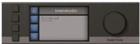
The functionality of the four tactile push buttons on the left side depends on the current mode and position in the menu structure. Icons on the left side of the display are indicating the current functionality linked with the buttons.
The rotary selection dial can be used for parameter adjustments and browsing to station lists, playlists or any other. This multifunctional dial allows easy one—hand operation throughout the entire menu structure. Browsing is done by rotating it while actions are made by pressing it.
The functionality for each icon is indicated in following table:
| ICON DESCRIPTION | |
 | Show station list |
 | Go to internet radio settings |
 | Go to general settings |
 | Mark / save current selection as favourite |
 | Go back to system main screen |
 | Go one step back |
 | Erase current selection |
Database updates
The ISP40 comes with the vTuner database pre-loaded. Since continuously new radio stations are being added, it is recommended to manually start the database update process when using it for the first time. How to start the manual update process is described in the ISP40 Settings > DB info chapter of this instruction manual.
When operational, the ISP40 will regularly check with the database server whether a new update is available, and if so, automatically start the database update process without any noticeable consequences for the user / listener.
Main screen
The main screen gives an overview of the ISP40's current operation mode. The name of the currently playing station including additional carried information such as track name, program name, ... will be indicated on this screen.
Station selection:
The Station list) button gets you to the vTuner database overview where the radio station selection can be made by hand of various criteria, such as genre, location or stored favourites.

Settings:
The ESP40 settings) button gets you to the ISP40 settings menu where all configurations related to the audio, database and network can be configured.
Favourites:
The ☆ (Favourites) button stores the currently playing channel to the favourites list which can contain a maximum up to 100 entries.
General settings:
The ✗General settings) button gets you to the general settings menu where all general settings for the device can be configured.
Station selection
The station selection screen allows radio stations selection though the vTuner database which includes over 30.000 channels. Selection of the radio station is done by hand of various criteria, such as favourites (includes the stored channels), location, genre, ...
When the main criteria is selected, the menu will guide you through the next step of selection criteria including all different continents, countries, genres, ... and so on.

Browsing through the menu structure is done by turning the function dial, while selections are made by pressing it. The ✉ button gets you one step back in the station selection overview.
Once the desired channel has been found, press the function dial for selection and the channel will start playing.
ISP40 Settings screen
The settings menu for ISP40 is loaded when pressing the ⚙ISP40 settings) button.
Output gain:
The gain can be adjusted within a range of +8 dB and -92 dB, allowing optimization of the output level according to the input sensitivity of the connected amplifier or pre-amplifier. For adjusting the output gain, rotate the function dial until 'Gain' is highlighted and press it for proceeding to the gain settings. The level can be adjusted by rotating clockwise (tuning up) or counter-clockwise (tuning down). Press the rotary dial for confirming the currently set output level.

DB info:
DB info gives the version information regarding the currently loaded vTuner database which contains all station information.
The autoupdate function allows automatic updating of the database. When enabled, the ISP40 automatically synchronizes with the database server whether a new update becomes available, and if so, automatically start the database update process without any noticeable consequences for the user / listener. Autoupdate is standard configured as ON but can be disabled (switched to OFF).
Manual database updating can be started by selecting 'Start Database Update'. When selected, the currently stored database will be removed and the latest version is retrieved from the server. The database update process can take few minutes before completed.
IP settings:
When highlighting the IP settings button is, an overview of the currently configured network settings is given on the right screen side. When selected, a separate IP settings menu will be loaded where all network settings can be customized.
DEFAULT NETWORK SETTINGS
DHCP: ON
IP address: Assigned by DHCP
Subnet mask: Assigned by DHCP
Gateway: Assigned by DHCP
DNS 1: Assigned by DHCP
DNS 2: Assigned by DHCP
IP Settings > DHCP:
In default configuration, the DHCP function for the ISP40 is enabled whereby the IP address and other network settings are automatically assigned through the DHCP server in your network.
Since the ISP40 doesn't support any control commands from other devices over TCP/IP in contrast to other TCP/IP control supporting devices, the ISP40 doesn't need to have a ‘fixed’ for being reachable through other devices.
IP settings > IP address:
The IP address for the system can be configured in this window. Each section of the IP address can be individually adjusted by turning the rotary dial (clockwise for up, and counter-clockwise for down). The currently adjusting section will be indicated in blue colour. Once the correct number for the current section is selected, proceed to the next section by pressing the rotary dial.
IP settings > Other network settings:
All other network settings such as subnet mask, Gateway, DNS 1 and DNS 2 can be configured in this window. The default configuration is set to DHCP, however in case of special network restrictions or requirements, consult your network administrator for more details on the network settings.
All additional network settings can be modified in similar way as the IP address, allowing adjustments by turning and pressing of the rotary dial.
Station info:
Gives additional information about the currently playing station. Displayed information includes station name, category, country, city, sample rate, bitrate, connections, playtime, ...
Add station:
Custom audio streams (not included in the vTuner database) can be manually added to the ISP40 stations list. This feature allows specific broadcast streams from corporate headquarters to various branch offices, or specific audio streams which are not public accessible to be added to the system.
For adding specific audio streams, the corresponding URL shall get entered to the system, and a specific stream name shall be given. Entering this data is done by selection of the characters through turning the function dial, while selections are made by pressing it.
Once the URL is entered, select save to proceed to the stream name. When both are entered, select save again to confirm stream details and go back to the settings screen. The entered stream is now added to the favourites list.
Factory reset:
Factory reset will recall all settings to factory defaults and all previously made settings and configurations will be lost. After selecting factory reset, a confirmation will be asked whether all settings definitely need to be reset to factory defaults. When confirmed, all settings will be lost.
Back:
Returning to the main screen is done by selecting 'Back'.
General settings
The general settings menu for ISP40 is loaded when pressing the ✗(general settings) button. The general settings menu allows to configure all the global settings for the ISP40 unit, keeping aside the audio, database and network settings.
Lock:
When selecting 'Lock', the system will be locked and will require a password to be entered before any further action can be taken (if the password is enabled).

Info:
Info will give an overview of the software versions the ISP40 is running.
LCD Settings:
Adjustments for the LCD settings can be made here. The brightness can be adjusted within a range of 10% to 100% (standard is 80%). Adjusting of the LCD brightness can be convenient when the device is placed in an environment with very low or very high ambient light. Hereby the clarity of the LCD can be adjusted being clear but unobtrusive.
The backlight off time can be adjusted within an interval of 10 up to 120 minutes or never (always on), making the backlight of the LCD automatically turn off after the set time.
Password:
Password protection can be enabled, avoiding unauthorized users to make any adjustment to the system. The password is a four-digit code. In default, the password is set to '0000' which gives full access to the system without requiring any password to be entered. If the configured password is different from '0000', the user will be requested to enter the password before any access to the systems functions is provided.
The currently set password will be shown and the adjusting digit can be selected (turns red) and confirmed by turning and pressing the rotary selection dial. Consecutive digits will increase when the maximum value has been reached.
After the desired password has been selected it can be confirmed by pressing (turns red) and turning the function dial clockwise to the entire right side where the 'OK' word will appear. After pressing again the password is confirmed.
Back:
Returning to the main screen is done by selecting 'Back'.
Chapter 4
Additional information
IP Basics
Many AUDAC products are controllable by Ethernet. The Ethernet connection which is used on the AUDAC products is TCP/IP based, like 99% of the computer networks. There are some basics which you need to know to successfully make a TCP/IP Ethernet connection.
The data in TCP/IP networks is always send in packages, all these packages must be delivered at an unique address, just like the mailman delivers mail at your home mailbox. In TCP/IP networks, this address is called the "IP address". The IP address is always a number in the following format "192.168.000.001". As you can see, this address consists of 4 separate numbers ranging from "000" to "255".
In simple terms, only the latest number of an IP address can be different within a network, so there is a maximum of 254 unique addresses within a network, ranging from "xxx.xxx.xxx.001" to "xxx.xxx.xxx.254". The first three numbers must be the same to make communication between several devices possible, else the devices can not communicate with each other.
Example:
Device 1: IP address: 192.168.000.001
Device 2: IP address: 192.168.000.002
Device 3: IP address: 192.168.001.003
In this example, Device 1 can communicate with Device 2, but not with Device 3, because the first three numbers must be the same. These first three parts are called the "IP range", so the devices must be in the same "IP range" to communicate with each other.
The “IP range” of home and office networks are defined by the network administrator, this means that the IP range of your home or office network can be different from another network. AUDAC products have the following IP address as default: “192.168.0.xxx”, this means the standard IP range of AUDAC products is “192.168.000.xxx”. If your network is using a different IP range, the AUDAC products will not be accessible from your network. You can change the IP address of the AUDAC products to make them work properly in your network. This can be done in the settings menu, and is described extensively in the “Settings” chapter of this user manual.
Ask your network administrator for help if you are not familiar with networks.
Summary
– All devices must have an unique IP address
– All devices must be within the same IP range
Technical specifications
| Input | RJ45 | Ethernet | connection | ||
| Output | Balanced | stereo | line | output | |
| (2 x 3-pin Euro Terminal Block ~ 3.81 mm) | |||||
| Output level | +8 dB ~ -92 dB | (Software configurable) | |||
| Supported filetypes streaming MP3, WMA, AAC | |||||
| Control | Front | panel | |||
| RS232 | (DB9 | connector) | |||
| RMT40 | Remote | control | (optional) | ||
| Display | 2.8" | Graphical | LCD | ||
| Signal/noise | 94 | dB | |||
| THD+N | < | 0.07% | |||
| Frequency response | 20 Hz – 20 kHz | ||||
| Crosstalk | 80 | dB | |||
| Power supply | Type | Switching mode | |||
| Range | 100–240V AC – 50/60 Hz | ||||
| Power consumption | 1.6 Watt | ||||
| Dimensions (W x H x D) | 482 x 44 x 330 mm | ||||
| Weight | 3.15 | Kg | |||
| Unit height | 1 | HE | |||
| Optional accessories | RMT40 RF remote control – 2.4 GHz | ||||
Notes
Notes
- Index
- Introduction 5
- Precautions 6
- Chapter 1: Pin connections and connectors 9
- Chapter 2: Front & rear panel 10
- Chapter 3: Using the ISP40 12
- Chapter 4: Additional information 17
- Introduction
- Professional internet audio player
- Precautions
- READ FOLLOWING INSTRUCTIONS FOR YOUR OWN SAFETY
- CAUTION - SERVICING
- EC DECLARATION OF CONFORMITY
- WASTE ELECTRICAL AND ELECTRONIC EQUIPMENT (WEEE)
- CAUTION
- Chapter 1
- Pin connections and connectors
- CONNECTION STANDARDS
- 3-Pin Terminal Block:
- RS232 (serial connection interface):
- RS232
- Chapter 2
- Front & rear panel
- Front Panel overview
- Front panel description
- Graphical LCD display with tactile push buttons and rotary selection dial:
- Power switch:
- Rear Panel overview
- Rear panel description
- AC Power inlet with fuse:
- RS232 Connection:
- USB (Update) Connection:
- Balanced stereo line output:
- Ethernet RJ45 Connector:
- Chapter 3 Using the ISP40
- Database updates
- Main screen
- Station selection:
- Settings:
- Favourites:
- General settings:
- Station selection
- ISP40 Settings screen
- Output gain:
- DB info:
- IP settings:
- DEFAULT NETWORK SETTINGS
- IP Settings > DHCP:
- IP settings > IP address:
- IP settings > Other network settings:
- Station info:
- Add station:
- Factory reset:
- Back:
- General settings
- Lock:
- Info:
- LCD Settings:
- Password:
- Chapter 4
- Additional information
- IP Basics
- Example:
- Summary
- Notes
Brand : Audac
Model : ISP40
Category : Media player