
SWADS-GATEAK - Doorbell SWANN - Free user manual and instructions
Find the device manual for free SWADS-GATEAK SWANN in PDF.


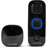
| Product Type | Wired Doorbell with Internal Chime |
| Brand | Swann |
| Model | SWADS-GATEAK |
| Push Button Dimensions | Approx. 3.1 x 2.1 x 0.9 inches (80 x 54 x 22 mm) |
| Chime Unit Dimensions | Approx. 4.7 x 3.3 x 1.4 inches (120 x 85 x 35 mm) |
| Combined Weight | Approx. 6.3 oz (180 g) |
| Power Supply | 8-24 V AC, 50/60 Hz |
| Power Consumption | Standby: < 0.5W, Active: < 2W |
| Wireless Range | Not applicable (wired connection) |
| Waterproof Rating | Button: IP54, Chime: Indoor use only |
| Number of Melodies | 8 selectable tunes |
| Volume Control | Adjustable via chime unit knob |
| Indicator LED | Flashes on button press (optional) |
| Materials | Button: ABS plastic, Chime: ABS plastic |
| Installation | Surface mount or flush mount; instructions included |
| Maintenance | Wipe with dry cloth; avoid water and solvents |
| Safety | Complies with low voltage safety standards (EN 62368-1) |
| Spare Parts | Push button and chime unit available separately |
| Repairability | Replaceable fuse in chime unit; user-serviceable |
| Included Accessories | 1 push button, 1 chime unit, 2 screws, 1 user manual |
| Warranty | 1 year limited warranty |
Frequently Asked Questions - SWADS-GATEAK SWANN
User questions about SWADS-GATEAK SWANN
0 question about this device. Answer the ones you know or ask your own.
Ask a new question about this device
Download the instructions for your Doorbell in PDF format for free! Find your manual SWADS-GATEAK - SWANN and take your electronic device back in hand. On this page are published all the documents necessary for the use of your device. SWADS-GATEAK by SWANN.
USER MANUAL SWADS-GATEAK SWANN
Thank you for choosing the Gate Alert Kit from Swann. It's the ideal system to detect unwanted access into a restricted area through the gate or door.
How does it work?
Basically, there are two parts to the Gate Alert Kit.
- The Indoor Alarm Receiver works as an alarm buzzer. It monitors for signals coming from the Gate Sensor, and activates the alarm and channel LED indicator in response to that signal.
- The Gate Sensor consists of a wired switch and a magnet which help safeguard a gate or door from being opened without your knowledge. If the Delay button is not pressed and the gate or door is opened, the Gate Sensor sounds its built-in siren immediately and sends a signal to the Indoor Alarm Receiver.
Getting to know your Gate Sensor

Getting to know your Indoor Alarm Receiver
![graph TD A["Doorbell LED*"] --> B((Bell)) C["Channel 1 LED"] --> B D["Channel 2 LED"] --> B E["Channel 3 LED"] --> B B --> F["①"] B --> G["②"] B --> H["③"]](/content/2026/06/1288215/images/7e664dbfd6901faf5d5f03806d62c6f9eb2f1d9d14bf25f1457c93e11151b7fa.jpg)

Your Gate Sensor is assigned to channel 1 by default. Each channel is capable of supporting up to 15 sensor devices. Features denoted with * require separate purchase of an add-on Doorbell.
Battery Safety Information
Replace batteries at the same time. Do not mix new and old batteries or battery types (for example, alkaline and lithium batteries). Keep batteries out of reach of children. Dispose of used batteries promptly in accordance with local regulations.
Indoor Alarm Receiver
Installing batteries
- Push the release tab and lift off the battery compartment cover.
- Insert 3 new "AA" alkaline batteries, matching the polarity markings (+ and -) inside the battery compartment.
- Put the battery compartment cover back on by pressing down until the release tab clicks into place.
Placing your receiver
There is no requirement to mount the Indoor Alarm Receiver. As it is also completely freestanding, you may find it more convenient to place it on a shelf or table. One of the benefits of a battery operated wireless receiver is that if you have a large house, you can take the receiver with you. No more missing visitors because you were all the way at the back of the house or by the pool!
If you would like to mount the Indoor Alarm Receiver, we've included all the gear (template, screws and wall plugs) you'll need to hang it on the wall. Refer to the supplied template for instructions on mounting the receiver.
Gate Sensor
CAUTION: The Gate Sensor siren is extremely loud! Protect your hearing by wearing earplugs.
Installing batteries
The Gate Sensor requires 3 x AAA batteries (not included) to operate.
- Remove the screws from the battery compartment cover, and then lift up the cover.
- Insert 3 new "AAA" alkaline batteries, matching the polarity markings (+ and -) inside the battery compartment.
- Screw the battery compartment cover back into place.

Mounting the Gate Sensor
The Gate Sensor can be easily mounted to a surface next to a gate/door using the included mounting plate, screws and wall plugs (if mounting to brick or concrete). Be sure to install the Gate Sensor high enough so it's out of reach of small children.
Mounting the switch and magnet

The sensor switch and magnet are each fitted with an adhesive strip. Stick the sensor on the gate/door frame (the stationary part), and the magnet on the gate/door (the moving part) itself. Press firmly against surface for 30 seconds to create a strong bond. For proper detection, the sensor and magnet must be aligned side by side with their arrows pointing to each other, no more than 3/8" apart.
OPERATING BASICS
Bypass feature
The Gate Sensor provides a 7-second delay in which you can open the protected gate or door, and close it, without sounding the alarm. Simply press the Delay button before opening the gate or door. The status LED on the Gate Sensor will blink to indicate "Bypass" is on. If the gate or door is not closed within this time frame, the Gate Sensor will sound immediately (for 6 seconds in 3 cycles) and also set off the Indoor Alarm Receiver. To stop the alarm, close the gate or door.
Adjusting the alarm volume
You can change the loudness of the Indoor Alarm Receiver using the Volume button on the back of the receiver.
Three volume levels are available: High, Medium and Low.
Silent mode
Like some peace and quiet for a period of time from the Indoor Alarm Receiver? You can put the alarm triggered by the Gate Sensor on “silent”. Simply press the Channel button that corresponds with the Gate Sensor. The Indoor Alarm Receiver beeps twice, confirming the alarm has been turned off.

If the Gate Sensor is triggered while the alarm is muted, you will still be visually alerted by the corresponding Channel LED indicator blinking on the Indoor Alarm Receiver. Note that muting the receiver does not also prevent the Gate Sensor from sounding.

To unmute the alarm, press the corresponding Channel button again. You will hear a single confirmation beep from the Indoor Alarm Receiver.
Low battery warning
Your devices will let you know when batteries are running low on power.
• Install new batteries immediately for the Indoor Alarm Receiver when all four LED indicators start blinking at the same time.
• Install new batteries immediately for the Gate Sensor when the status LED starts blinking continuously.
Re-pairing your Gate Sensor / Changing channel
The Gate Sensor and Indoor Alarm Receiver in your kit have been factory paired so all you have to do is put batteries in and your devices are ready to use. If for some reason pairing is lost or you just want the Gate Sensor paired to another channel for a different alarm (each channel has a distinct sound), here's how to do it:
- Make sure the sensor switch and magnet is in a "closed" position (if mounted, the gate or door should be closed).
- Press and hold the Reset button on the back of the Indoor Alarm Receiver until all the LED indicators light up. This resets the receiver.
- Decide which channel (1, 2 or 3) you want to assign the Gate Sensor to, and then press and hold the desired Channel button on the back of the Indoor Alarm Receiver until the LED indicator for that channel lights up.
- Within 10 seconds, trigger the Gate Sensor by separating the sensor switch and magnet (if mounted, open the gate or door). The Indoor Alarm Receiver sounds the channel alarm and flashes the channel LED to confirm successful pairing.
Technical Support
All Countries E-mail: tech@swann.com
Telephone Helpdesk
USA 1800 627 2799
AUSTRALIA 1800 788 210
NEW ZEALAND 0800 479 266
UK
0808 168 9031
Limited Warranty Terms & Conditions
Swann Communications warrants this product against defects in workmanship and material for a period of one (1) year from it's original purchase date. You must present your receipt as proof of date of purchase for warranty validation. Any unit which proves defective during the stated period will be repaired without charge for parts or labour or replaced at the sole discretion of Swann. The end user is responsible for all freight charges incurred to send the product to Swann's repair centres. The end user is responsible for all shipping costs incurred when shipping from and to any country other than the country of origin.
The warranty does not cover any incidental, accidental or consequential damages arising from the use of or the inability to use this product. Any costs associated with the fitting or removal of this product by a tradesman or other person or any other costs associated with its use are the responsibility of the end user. This warranty applies to the original purchaser of the product only and is not transferable to any third party. Unauthorized end user or third party modifications to any component or evidence of misuse or abuse of the device will render all warranties void.
By law some countries do not allow limitations on certain exclusions in this warranty. Where applicable by local laws, regulations and legal rights will take precedence.
For Australia: Our goods come with guarantees which cannot be excluded under Australian Consumer Law. You are entitled to a replacement or refund for a major failure and for compensation for any other reasonably foreseeable loss or damage. You are also entitled to have the goods repaired or replaced if the goods fail to be of acceptable quality and the failure does not amount to major failure.
FCC Verification
This equipment has been tested and found to comply with the limits for Class B digital device, pursuant to part 15 of the FCC Rules. These limits are designed to provide reasonable protection against harmful interference in a residential installation. This equipment generates, uses and can radiate radio frequency energy and, if not installed and used in accordance with the instructions, may cause harmful interference to radio or television reception, which can be determined by turning the equipment off and on, the user is encouraged to try to correct the interference by one or more of the following measures:
- Reorient or relocate the receiving antenna
- Increase the separation between the equipment and the receiver
- Connect the equipment into an outlet on a circuit different from that to which the receiver is connected
- Consult the dealer or an experienced radio/TV technician for help
WARNING: Modifications not approved by the party responsible for compliance could void user's authority to operate the equipment.

Swann.
Advanced Security Made Easy

- HOW DOES IT WORK
- GETTING TO KNOW YOUR GATE SENSOR
- BATTERY SAFETY INFORMATION
- INDOOR ALARM RECEIVER
- INSTALLING BATTERIES
- PLACING YOUR RECEIVER
- GATE SENSOR
- MOUNTING THE GATE SENSOR
- MOUNTING THE SWITCH AND MAGNET
- OPERATING BASICS
- BYPASS FEATURE
- ADJUSTING THE ALARM VOLUME
- SILENT MODE
- LOW BATTERY WARNING
- RE-PAIRING YOUR GATE SENSOR / CHANGING CHANNEL
- TECHNICAL SUPPORT
- TELEPHONE HELPDESK
- LIMITED WARRANTY TERMS & CONDITIONS
- FCC VERIFICATION
Brand : SWANN
Model : SWADS-GATEAK
Category : Doorbell