
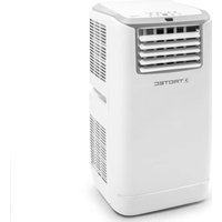
PAC 3200 E - Air conditioner TROTEC - Free user manual and instructions
Find the device manual for free PAC 3200 E TROTEC in PDF.


| Product Type | Portable Air Conditioner |
| Model | PAC 3200 E |
| Brand | Trotec |
| Cooling Capacity | Approx. 3200 BTU/h (estimated) |
| Dimensions (W x D x H) | Approx. 35 x 40 x 70 cm (estimated) |
| Weight | Approx. 25 kg (estimated) |
| Power Supply | 230 V / 50 Hz (typical for European models) |
| Power Consumption | Approx. 1000 W (estimated) |
| Refrigerant | R290 (common for portable ACs) or similar |
| Airflow Rate | Approx. 300 m³/h (estimated) |
| Noise Level | Approx. 55 dB (estimated) |
| Functions | Cooling, dehumidifying, fan, temperature control |
| Controls | Digital display with remote control (typical) |
| Installation | Window exhaust kit included, portable floor-standing |
| Condensate Drainage | Continuous drain via hose or manual tank |
| Filter | Washable air filter |
| Maintenance | Clean filter every 2 weeks; drain condensate regularly |
| Safety Features | Overheat protection, auto shut-off, tip-over switch (estimated) |
| Spare Parts | Filter, remote control, exhaust hose, window kit |
| Repair | Contact authorized service center; do not open refrigerant circuit |
| Warranty | Standard manufacturer warranty (2 years typical) |
Frequently Asked Questions - PAC 3200 E TROTEC
User questions about PAC 3200 E TROTEC
0 question about this device. Answer the ones you know or ask your own.
Ask a new question about this device
Download the instructions for your Air conditioner in PDF format for free! Find your manual PAC 3200 E - TROTEC and take your electronic device back in hand. On this page are published all the documents necessary for the use of your device. PAC 3200 E by TROTEC.
USER MANUAL PAC 3200 E TROTEC
natural_image
White Trotec air conditioner unit with ventilation slots and control panel (no visible text or symbols on body)table of contents
Notes regarding the operating manual.... 1
Safety 2
Information about the device.... 3
Transport and storage.... 4
Assembly and installation.... 5
Operation 7
Errors and faults.... 11
Maintenance 13
Technical annex....16
Disposal 21
Declaration of conformity 21
Notes regarding the operating manual
Symbols

Hazardous electric current!
Warns about hazards from electric current which can lead to injuries or even death.

Danger!
Warns of a hazard which can lead to personal injury.

Caution!
Warns of a hazard which can lead to property damage.
The current version of the operating manual can be found at:

natural_image
Icon of a person reading a book inside a gray circle (no text or symbols)PAC 3200 E A+

http://download.trotec.com/?sku=1210002050&id=1
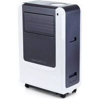
PAC 4100 E

http://download.trotec.com/?sku=1210002150&id=1
Legal notice
This release replaces all previous versions. No part of this publication may be reproduced without written permission from Trotec GmbH & Co. KG. The same applies for electronically processing, duplicating or spreading the publication. Subject to technical changes. All rights reserved. Trademarks are used without guarantee that they may be used freely and primarily following the spelling of the manufacturer. Product names are registered.
Changes to construction in the interests of constant improvements to the product, as well as changes to the shape and colour are reserved.
The scope of delivery may vary from product images. This document was created with all due care. Trotec GmbH & Co. KG accepts no liability whatsoever for possible mistakes or omissions.
Warranty and liability
The device complies with the fundamental health and safety requirements of the applicable EU regulations and was tested at the factory for perfect functionality multiple times.
However, if faults in the functionality occur and cannot be remedied with the measures in the chapter Errors and faults, please get in touch with your dealer or distributor.
When making a warranty claim, supply the device number (see the rear of the device).
When manufacturer's instructions or legal regulations have not been followed, or after unauthorised changes to the device are made, the manufacturer is not responsible for the resulting damages. Changes to the device or unauthorised replacement of individual parts can drastically impact the electrical safety of this product and leads to the forfeit of the warranty. Liability does not extend to damages to people or property caused by the device being used other than as described in the instructions in this operating manual. Subject to changes to technical design and model changes as part of constant development and product improvement without prior notice.
No liability is accepted for damages resulting from improper use. In such a case, any warranty claims be voided also.
Safety
Read this manual carefully before starting or using the device. Always store the manual in the immediate vicinity of the device or its site of use!
- Do not use the device in potentially explosive rooms.
- Do not use the device in aggressive atmosphere.
- Set the device up in an upright and stable position.
- Let the device dry out after a wet clean. Do not operate it when wet.
- Do not use the device with wet or damp hands.
- Do not expose the device to directly squirting water.
- Never insert any objects or limbs into the device.
- Do not cover or transport the device during operation.
- Do not sit on the device.
- This appliance is not a toy! Keep away from children and animals. Do not leave the device unattended during operation.
- Check accessories and connection parts for possible damage prior to every use of the device. Do not use any defective devices or device parts.
- Ensure that all electric cables outside of the device are protected from damage (e.g. caused by animals). Never use the device if electric cables or the power connection are damaged!
- The electrical connection must correspond to the specifications in chapter Technical data.
- Insert the mains plug into a properly secured mains socket.
- Observe the device's power input, cable length and intended use when selecting extensions to the power cable. Completely unroll extension cables. Avoid electrical overload.
- Before carrying out maintenance, care or repair work on the device, remove the mains plug from the mains socket. Hold onto the mains plug while doing so.
- Switch the device off and disconnect the power cable from the mains socket when the device is not in use.
- Do not under any circumstances use the device if you detect damages on the mains plug or power cable. Defective power cables pose a serious health risk.
- Observe the storage and operating conditions (see chapter Technical data).
- Ensure that the air inlet and outlet are not obstructed.
- Ensure that the side of the device where the air inlet is found is kept free of dirt and loose objects.
- Only transport the device in an upright position with an emptied condensation tank or drain hose.
- Discharge the collected condensate before transport and storage. Do not drink it. Health hazard!
Intended use
Only use the device for cooling, ventilating and dehumidifying indoor air whilst adhering to the technical data.
Improper use
- Do not place the device on wet or flooded ground.
- Do not place any objects, e.g. clothing, on the device.
- Do not use the device outdoors.
- Any unauthorised modifications, such as alterations or structural changes to the device, are forbidden.
- Any operation other than as described in this manual is prohibited. Non-observance renders all claims for liability and guarantee null and void.
Personnel qualifications
People who use this device must:
- be aware of the dangers that occur when working with electric devices in damp areas.
- have read and understood the operating manual, especially the Safety chapter.
Maintenance tasks which require the housing to be opened must only be carried out by specialist companies for cooling and air-conditioning or by Trotec.
Residual risks

Hazardous electric current!
Work on the electrical components must only be carried out by an electrically skilled person or an authorised specialist company.

Hazardous electric current!
Before any work on the device, remove the mains plug from the mains socket!
Hold onto the mains plug while pulling the power cable out of the mains socket.

Danger!
Dangers can occur at the device when it is used by untrained people in an unprofessional or improper way! Observe the personnel qualifications!

Danger!
The device is not a toy and does not belong in the hands of children.

Danger!
Do not leave the packaging lying around. Children may use it as a dangerous toy.

Caution!
Do not operate the device without an inserted air filter! Without air filter the inside of the device will be heavily contaminated, this could reduce the dehumidification performance and result in damage to the device.
Behaviour in the event of an emergency
-
In an emergency, disconnect the device from the mains feed-in: Switch the device off and disconnect the power cable from the mains socket. Hold onto the mains plug while doing so.
-
Do not reconnect a defective device to the mains.
Information about the device
Device description
The device serves the purpose of cooling the room air. It further filters and dehumidifies the air thus creating an agreeable room climate.
In ventilation mode the device also provides the opportunity of air circulation without cooling effect.
In dehumidification mode moisture is withdrawn from the air.
The device operates fully automatically and features a variety of further options, the device can, for instance, be switched on or off automatically with time delay via the timer function.
Handling the device can be accomplished via the control panel at the device or the supplied infrared remote control.
The device was designed for universal and flexible application.
Due to its compact dimensions it can be easily transported and used in all interior spaces.
The unit cools the room air by withdrawing warmth. The absorbed warmth is emitted to the outside via the exhaust air hose, cooled air is fed to the installation site by means of a fan.
Accumulating condensate trickles from the evaporator onto the hot condenser, there it evaporates and then is transported to the outside via the exhaust air hose.
Device depiction

| No. Designation | |
| 1 Air inlet with air filter | |
| 2 Cable storage compartment with power cable | |
| 3 Exhaust air hose connection | |
| 4 Hose connector with sealing cap and rubber stopper | |
| 5 Exhaust air hose | |
| 6 Remote control | |
| 7 Wheels | |
| 8 Control panel | |
| 9 Water funnel and filling level indication for energy saving | |
| 10 Air outlet with ventilation flaps | |
| 11 Remote control receiver |
Transport and storage
Transport
Before transporting the device, proceed as follows:
- Switch off the device.
- Hold onto the mains plug while pulling the power cable out of the mains socket.
- Drain the remaining condensate from the device and the condensation drain hose (see Maintenance and cleaning chapter).
- To make the device easier to transport, it is fitted with wheels.
- Do not use the power cable to drag the device.
- Only wheel the device on a level and smooth surface.
After transporting the device, observe the following:
- Set up the device in an upright position after transport.
- Leave the device to rest for 12 - 24 hours, so the refrigerant can accumulate within the compressor. Wait 12 - 24 hours before switching the device back on! Acting contrary might lead to compressor damage and a malfunctioning device. If so, any warranty claims will be voided.
Storage
Before storing the device, proceed as follows:
- Drain the remaining condensate from the device and the condensation drain hose (see Maintenance and cleaning chapter).
When the device is not being used, observe the following storage conditions:
- dry and protected from frost and heat,
- in an upright position where it is protected from dust and direct sunlight,
- with a cover to protect it from invasive dust, if necessary.
- Place no further devices or objects on top of the device to prevent it from being damaged.
- Remote batteries from the remote control.
Assembly and installation
Scope of delivery
- Device
- Exhaust air hose
• Condensation drain hose, length: 1 m, diameter: 18 mm
• Air filter - Inserts for sliding window
- Window shade
- Remote control
- Hose connector
- Hose adapter
- Manual
Unpacking the device
- Open the cardboard box and take the device out.
- Completely remove the packaging.
- Fully unwind the power cable. Make sure that the power cable is not damaged and that you do not damage it during unwinding.
Start-up
When positioning the device, observe the minimum distance from walls or other objects as described in chapter Technical Data.

- Before restarting the device, check the condition of the power cable. If there are doubts as to the sound condition, contact the customer service.
- Set the device up in an upright and stable position.
- Do not create tripping hazards when laying the power cable or other electric cables, especially when positioning the device in the middle of the room. Use cable bridges.
- Make sure that extension cables are completely unrolled.
- Keep air inlets and outlets as well as the exhaust air hose connection free.
- Make sure that no curtains or other objects interfere with the air flow.
Prior to initial start-up, insert the batteries in the remote control.
Inserting the air filter

Caution!
Do not operate the device without an inserted air filter! Without air filter the inside of the device will be heavily contaminated, this could reduce the dehumidification performance and result in damage to the device.
- Make sure that the air filter is installed before switching the device on.

natural_image
Diagram of a satellite with solar panels and directional arrows indicating orientation (no text or labels)Connecting the exhaust air hose
- Screw the end of the exhaust air hose (5) counter-clockwise into the air conditioner's exhaust air hose connection (3).

natural_image
Line drawing of a dual-chamber HVAC unit connected to a coiled hose (no text or symbols)Discharging exhaust air
- The exhaust air coming from the device contains waste heat from the room to be cooled. For this reason it is advisable to discharge the exhaust air outside into the open air.
- The end of the exhaust air hose can be fed through the open window. If required, secure the open window with the corresponding means, so that the end of the exhaust air hose stays put.
- The end of the exhaust air hose can also be hooked into a tilted bottom-hung window.
For this purpose, we recommend using a window seal (optional).
• Install the exhaust air hose inclined with the air direction.
How to use the inserts
- Affix the inserts in the window gap and adjust the length as needed. If required, use the extension pieces.
- Connect the hose adapter to the insert.
- Close the window until the insert is held securely.
- Connect the end of the exhaust air hose to the hose adapter in the insert.

natural_image
Line drawing of an air conditioner unit emitting a hose near a window (no text or symbols)For installing the exhaust air hose please observe the following:

natural_image
Technical line drawing of a mechanical or electrical component with no visible text or symbols
natural_image
Diagram of a curved duct or pipe system with a vertical support structure, no text or symbols present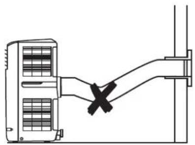
natural_image
Diagram of a mechanical or electrical component with a cross mark indicating a fault or connection point (no text or symbols present)
natural_image
Technical line drawing of a mechanical device with a handle and cross mark (no text or symbols)- Avoid kinks and bends in the exhaust air hose, as they would lead to an accumulation of emitted humid air causing the device to overheat and shut down.
- The dimensions of the exhaust air hose were especially made to fit the device. Do not replace or extend the hose, for it could cause a malfunction.
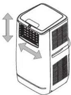
Opening the ventilation flaps
- Prior to switching the device on, open the ventilation flaps at the air outlet.
natural_image
Illustration of a portable air conditioner unit with bidirectional arrows indicating airflow or movement (no text or symbols)Connecting the power cable
- Insert the mains plug into a properly secured mains socket.
Operation
- Avoid open doors and windows.
Operating elements
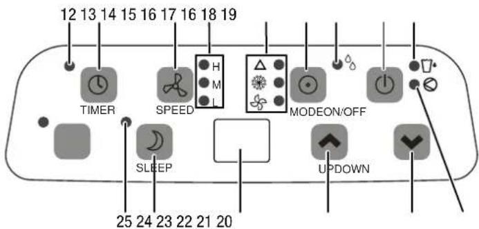
| No. Designation Meaning | |||
| 12 | TIMER LED | illuminated when the timer function is active | |
| 13 | TIMER button | for setting the timer function, 0 to 24 hours in increments of 1 h | |
| 14 | SPEED button | for setting the fan speed in 3 levels: high, medium and low | |
| 15 | Fan stage LED | H high fan speed | |
| M medium fan speed | |||
| L low fan speed | |||
| 16 | Operating mode LED | △ | automatic operation |
| (9324) | cooling | ||
| (7776) | ventilation | ||
| (30W4) | dehumidification | ||
| 17 | MODE button | selection button for the mode of operation | |
| 18 | ON/OFF button | On/Off button: to switch the device on or off | |
| 19 | Condensation tank full LED | condensate collection container is full and has to be emptied (see chapter Maintenance) | |
| 20 | Compressor LED | illuminated when the compressor is running | |
| 21 | Reduce temperature button (DOWN) | to set the target temperature for cooling between 18 and 32 °C | |
| 22 | Increase temperature button (UP) | ||
| 23 | Display | displays the current room temperature when in operation displays the target temperature while setting it indicates the timer | |
| 24 | SLEEP button | to de-/activate night mode | |
| 25 | Night mode LED illuminated | when night mode is activated | |
Switching the device on
- Allow the device to rest for a time.
-
Once you have completely installed the device as described in the Start-up chapter, you can switch it on.
-
Press the ON/OFF button (18).
→ The device switches on.
⇒ The current room temperature will be indicated on the display (23).
→ The device runs in automatic operation mode.
The device switches off automatically when the condensation tank is full. The Condensation tank full LED (19) will be illuminated and an acoustic signal will be emitted.
Cooling
In cooling mode the room will be cooled down to a certain preselected temperature.
Cooling commences when the ambient temperature equals the set temperature + 3°C.
Default settings in cooling mode:
- The target temperature is preset to 24 °C.
- If the ambient temperature is greater than or equal to (≥) 27 °C (target temperature +3 °C), the device runs automatically in cooling mode. The following LED is illuminated in green:

- If the ambient temperature is less than or equal to (≤) 25°C (target temperature +1 °C), the device will automatically be in ventilation mode. The following LED is illuminated in green:

- Press the MODE button (17) until the LED for cooling (16,
lights up.

- Press the buttons for increasing (22) or reducing (21) the temperature to adjust the desired target temperature.
⇒ The target temperature flashes for approx. 5 s. Then the current room temperature will be displayed.
Dehumidification
In dehumidification mode the humidity level in the room is reduced.
The temperature cannot be adjusted and the fan runs at the lowest speed level.
- Press the MODE button (17) until the LED for dehumidification (16, ♂) lights up.
Note:
If the device is operated in a very humid environment, the condensation tank must be emptied at regular intervals (see Emptying the condensation tank in the Maintenance chapter).
If you use the device for a extended period of time or you don't want to empty the tank all the time, you can connect a condensation drain hose to the hose connection.
- Switch the device off.
- Hold onto the mains plug while pulling the power cable out of the mains socket.
- Carefully transport or wheel the device to a suitable location for discharging the condensate (e.g. a drain) or provide a suitable collection container.
- Unscrew the sealing cap from the hose connector (4).
- Remove the rubber stopper from the hose connection.
- Keep sealing cap and rubber stopper for later use.
- Connect the condensation drain hose included in the scope of delivery to the hose connector. Check the condensation drain hose for tight fit.
- Lead the condensation drain hose to a drain or sufficiently dimensioned collection container. To ensure that the condensate can run off, the condensation drain hose must not be kinked, nor should it have to overcome an uphill incline towards the drain.
- Insert the mains plug into a properly secured mains socket.
- Switch the device on.
Ventilation
In ventilation mode the room air is circulated, it will neither be cooled nor dehumidified.
Possible fan speed settings are:
- H = high fan speed
- M = medium fan speed
-
L = low fan speed
-
Press the MODE button (17) until the LED for ventilation (16,
) lights up.
- Press the SPEED button (14) to set the desired fan speed.
⇒ The LED for the selected fan speed (15) will be illuminated.
Automatic operation
In automatic operation mode both cooling and ventilation will be regulated depending on the ambient temperature and the preset target temperature of 24 °C.
- With an ambient temperature of more than 25 °C (preset target temperature +1 °C) the device automatically runs in cooling mode until the target temperature of 24 °C is reached. The following LEDs are illuminated in green:
△

- If the ambient temperature is less than or equal to (≤) 25°C, the device will automatically be operated in ventilation mode. The following LEDs are illuminated in green:
△

- Press the MODE button (17) until the LED for automatic operation (16, △) lights up.
The target temperature is preset to a fixed value of 24 ^ , it cannot be changed manually.
Setting the timer
The timer has two modes of operation:
- automatic switch-on upon expiry of a preset number of hours.
• automatic switch-off upon expiry of a preset number of hours.
The number of hours can be between 0 and 24 and can be adjusted in increments of 1 h.
Automatic switch-on
- Switch off the device.
- Press the TIMER button (13) until the desired number of hours is displayed.
- Wait for approx. 5 seconds in order to save the setting.
⇒ The TIMER LED (12) is illuminated.
→ The timer setting equals the desired number of hours.
⇒ The device starts in automatic operation mode after the set time has passed.
Notes regarding automatic switch-on:
- If the device is disconnected from the power supply, all settings for automatic switch-on are deleted.
- Manually switching the device on disables the automatic switch-on function.
- If you select 0 hours, the timer will be off.
Automatic switch-off
√ The device is switched on.
- Press the TIMER button (13) until the desired number of hours is displayed.
→ The number of hours flashes on the display.
- Wait for approx. 5 seconds in order to save the setting.
→ The display changes back to the normal indication.
⇒ The TIMER LED (12) is illuminated.
→ The timer setting equals the desired number of hours.
→ The device switches off after the set period of time.
Night mode
Night mode can only be activated in cooling mode. Night mode comes with the following settings:
- After one hour the preset temperature is increased by 1 °C. After 2 hours the preset temperature will again be increased by 1 °C. Then the temperature is kept constant.
- The fan speed is automatically lowered to the the min. level and cannot be changed manually.
• After 12 hours of operation in night mode the device switches off automatically.
To deactivate night mode, please proceed as follows:
- Press the SLEEP button (24).
→ The LED for night mode (25) will be illuminated.
⇒ The fan speed is automatically adjusted to the lowest level.
- In order to switch the night mode off, press the SLEEP button (24) once again.
→ The LED for night mode (25) goes out.
⇒ Fan speed and temperature will return to the level that was set before night mode was activated.
Energy saving
The device comes with an energy efficiency boosting function. The energy efficiency can be enhanced by filling water into the water funnel of the device.
√ The device is switched on.
√ The device has been in operation for at least one hour with the compressor.
- Open the water funnel (9).

natural_image
Line drawing of a portable air conditioner unit with a door and ventilation grille (no text or symbols)-
You can fill up to max. 2.5 l of water into the tank. In doing so, watch the filling level indication to the left of the water funnel.
-
Close the water funnel.
Note:
The condensation tank full LED (19) will light up if you fill too much water into the tank. If so, the condensation tank should be gradually emptied until the LED goes out again (see Emptying the condensation tank in the Maintenance chapter).
It is not possible to implement the energy-saving measure with a simultaneously connected condensation drain hose, for the water will immediately be drained from the tank.
Remote control
All settings of the device can also be made using the remote control included in the scope of delivery.
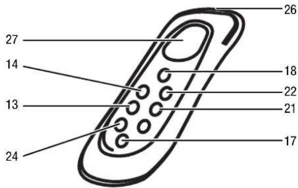
| No. Designation Meaning | |
| 13 TIMER button for setting the timer function, 0 to24 hours in increments of 1 h | |
| 14 SPEED button for setting the fan speed in 3 levels: high, medium and low | |
| 17 MODE button selection button for the mode of operation | |
| 18 ON/OFF button On/Off button: | to switch the device on or off |
| 21 Reduce temperature button (DOWN) | to set the target temperature for cooling between 18 and 32 °C |
| 22 Increase temperature button (UP) | |
| 24 SLEEP button to de-/activate night mode | |
| 26 Transmitter of the remote control | for infrared transmission to the remote control receiver (11) at the device |
| 27 Remote control display displays | the current room temperature when in operation displays the target temperature while setting it |
| △: automatic operation | |
| ☀️: cooling | |
| ☀️: ventilation | |
| ☀️: dehumidification | |
Shutdown

Danger!
Do not touch the mains plug with wet or damp hands.
- Switch off the device.
- Hold onto the mains plug while pulling the power cable out of the mains socket.
- If necessary, remove the condensation drain hose and any residual fluid from it.
- Empty the condensation tank, if need be.
- Clean the device according to the Maintenance and cleaning chapter.
- Store the device according to the Storage chapter.
Errors and faults
The device has been checked for proper functioning several times during production. If malfunctions occur nonetheless, check the device according to the following list.
The device does not start:
- Check the power connection.
- Check the mains plug for damages.
- Check the fuse (home).
- Observe the operating temperature according to the Technical data chapter.
- Check the filling level of the condensation tank and empty it, if necessary. The condensation tank full LED must not light up.
- Wait for 10 minutes before restarting the device. If the device is not starting, have the electrics checked by a specialist company or by Trotec.
The device works with reduced or no cooling capacity:
- Check whether cooling mode is selected.
- Check the proper fit of the exhaust air hose. In case of kinks, bends or blockage in the hose, exhaust air cannot be discharged. Clear the way for the exhaust air.
- Check the position of the ventilation flaps. They should be opened to the maximum.
- Check the air filter for dirt. If necessary, clean or replace the air filter.
- Check the minimum distance to walls or other objects. Position the device a little more in the room's centre, if required.
- Check whether there are opened windows and/or doors of the room. Close these, if any. The window for the exhaust air hose has to remain open nonetheless.
- Check the temperature setting at the device. Reduce the set temperature if it is higher than the room temperature.
The device is loud or vibrates:
- Check whether the device is set up in a stable and upright position.
Condensate is leaking:
- Check the device for leaks.
The compressor does not start:
- Check whether the overheating protection of the compressor has tripped. Disconnect the device from the mains and let it cool down for approx. 10 minutes before reconnecting it.
- Check whether the ambient temperature corresponds to the target temperature + 3 °C (in cooling mode) or to 25 °C (preset target temperature + 1 °C in automatic operation mode). The compressor will not switch on unless the target temperature is reached.
The device gets very warm, is loud or loses power:
- Check the air inlets and air filter for dirt. Remove external dirt.
- From the outside, check the device for dirt (see chapter Maintenance). If the inside of the device is dirty, have it cleaned by a specialist company for cooling and air-conditioning or by Trotec.
The device does not respond to the infrared remote control:
- Check whether the distance between remote control and device is too large and reduce it, if necessary.
- Make sure there are no obstacles, such as furniture or walls, between device and remote control. Ensure visual contact between device and remote control.
- Check the charging status of the batteries and change them, if required.
- If the batteries have only just been changed, check them for correct polarity and change them if required.
Note:
Wait for at least 3 minutes after maintenance and repair work. Only then switch the device back on.
Your device still does not operate correctly after these checks?
Please contact the customer service. If necessary, bring the device to a specialist company for cooling and air-conditioning or to Trotec for repair.
Error codes
The following error codes can be displayed:
| Error code Cause Remedy | |
| E1 Defective temperature sensor | Disconnect the device briefly from the mains.Should the error still be displayed after the restart, please contact the customer service. |
| E2 Defective coil sensor Disconnect the device briefly from the mains.Should the error still be displayed after the restart, please contact the customer service. | |
Maintenance
Maintenance intervals
| Maintenance and care interval before every start-up | as needed at least | every 2 weeks | at least every 4 weeks | at least every 6 months | at least annually |
| Empty condensation tank and drain hose X | |||||
| Check the air inlets and outlets for dirt and foreign objects and clean if necessary | X | X | |||
| Clean the exterior X X | |||||
| Visually check the inside of the device for dirt | X | X | |||
| Check the air filter for dirt and foreign objects and clean or replace if necessary | X | X | |||
| Replace air filter X | |||||
| Check for damage X | |||||
| Check the attachment screws X X | |||||
| Test run X |
Maintenance and care log
Device type: ....
Device number: ....
| Maintenance and care interval 1 2 3 4 5 6 | 7 8 9 | 10 11 12 | 13 14 | 15 16 | |||||||||||
| Empty condensation tank and drain hose | |||||||||||||||
| Check the air inlets and outlets for dirt and foreign objects and clean if necessary | |||||||||||||||
| Clean the exterior | |||||||||||||||
| Visually check the inside of the device for dirt | |||||||||||||||
| Check the air filter for dirt and foreign objects and clean or replace if necessary | |||||||||||||||
| Replace air filter | |||||||||||||||
| Check for damage | |||||||||||||||
| Check the attachment screws | |||||||||||||||
| Test run | |||||||||||||||
| Remarks: |
| 1. Date:......Signature:...... | 2. Date:......Signature:...... | 3. Date:......Signature:...... | 4. Date:......Signature:...... |
| 5. Date:......Signature:...... | 6. Date:......Signature:...... | 7. Date:......Signature:...... | 8. Date:......Signature:...... |
| 9. Date:......Signature:...... | 10. Date:......Signature:...... | 11. Date:......Signature:...... | 12. Date:......Signature:...... |
| 13. Date:......Signature:...... | 14. Date:......Signature:...... | 15. Date:......Signature:...... | 16. Date:......Signature:...... |
Activities required before starting maintenance

Danger!
Do not touch the mains plug with wet or damp hands.
- Switch off the device.
- Hold onto the mains plug while pulling the power cable out of the mains socket.

Danger!
Maintenance tasks which require the housing to be opened must only be carried out by authorised specialist companies or by Trotec.
Cleaning the housing
Clean the device with a soft, damp and lint-free cloth. Ensure that no moisture enters the housing. Protect electrical components from moisture. Do not use any aggressive cleaning agents such as cleaning sprays, solvents, alcohol-based or abrasive cleaners to dampen the cloth.
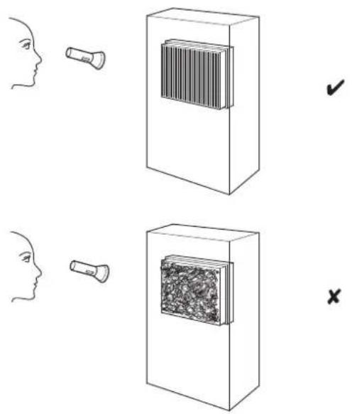
Visual inspection of the inside of the device for dirt
- Remove the air filter.
- Use a torch to illuminate the openings of the device.
- Check the inside of the device for dirt.
- If you see a thick layer of dust, have the inside of the device cleaned by a specialist company for cooling and air-conditioning or by Trotec.
- Put the air filter back in.
Cleaning the air filter
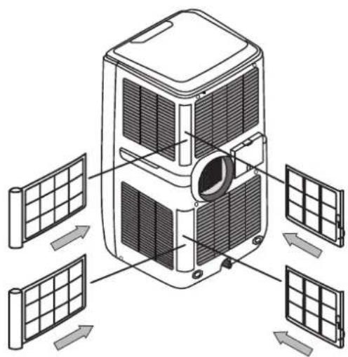
The air filter has to be cleaned as soon as it is dirty. This is brought to light e.g. by a reduced capacity (see chapter Errors and faults).

Caution!
Ensure that the air filter is not worn or damaged. The corners and edges of the air filter must not be deformed or rounded. Before reinserting the air filter, make sure that it is undamaged and dry!
- Remove the air filter from the device.

natural_image
Diagram of a satellite with solar panels and directional arrows indicating orientation (no text or labels)- Clean the filter using a slightly damp, soft, lint-free cloth. If the filter is heavily contaminated, clean it with warm water mixed with a neutral cleaning agent.
- Allow the filter to dry completely. Do NOT insert a wet filter into the device!
- Reinsert the air filter into the device.
natural_image
Diagram of a satellite with solar panels and directional arrows indicating orientation (no text or labels)Condensate discharge
In cooling and dehumidification mode condensate is formed, which is mostly discharged via the exhaust air.
The remaining condensate is collected in a container within the housing. The condensate ought to be drained regularly.
If too much condensate accumulates, the device switches off and indicates this via the Condensation tank full LED (19).
-
Carefully transport or wheel the device to a suitable location for discharging the condensate (e.g. a drain) or provide a suitable collection container.
-
Unscrew the sealing cap from the hose connector (4).

natural_image
Diagram showing a solar panel installation with a magnified inset illustrating airflow direction (no text or symbols)-
Remove the rubber stopper from the hose connection.
-
Let the condensate run, until the condensation hose is completely drained. Alternatively, you can connect the supplied condensation drain hose (see dehumidification mode).
-
Reattach the rubber stopper to the hose connector. Check the rubber plug for tight fit.
-
Screw the sealing cap onto the hose connector (4).
⇒ The condensation tank full LED (19) will go out as soon as the condensate has been drained.
Refrigerant circuit
- The entire refrigerant circuit is a maintenance-free, hermetically sealed system and may only be maintained or repaired by specialist companies for cooling and air-conditioning or by Trotec.
Activities required after maintenance
If you want to continue using the device:
- Leave the device to rest for 12 - 24 hours, so the refrigerant can accumulate within the compressor. Wait 12 - 24 hours before switching the device back on! Acting contrary might lead to compressor damage and a malfunctioning device. If so, any warranty claims will be voided.
- Reconnect the device to the mains.
If you do not intend to use the device for a considerable time:
- Store the device according to the Storage chapter.
Technical annex
Technical data
| Parameter Value | ||
| Model PAC 3200 E A+ PAC 4100 E | ||
| Cooling capacity 3.2 kW 4.1 kW | ||
| Dehumidification performance 1.16 l/h 1.6 l/h | ||
| Operating temperature 18 to 35°C 18 to 35°C | ||
| Temperature setting range 18 to 32°C 18 to 32°C | ||
| Max. air volume flow 500 m | ^3/h 500 m | ^3/h |
| Mains connection 1/N/PE~ 230 V / 50 Hz 1/N/PE~ 230 V / 50 Hz | ||
| Nominal current 4.6A | 7 A | |
| Power input (cooling operation) | 1.03 kW | 1.58 kW |
| Sound pressure level | 57 dB (A) 57 dB (A) | |
| Refrigerant | R410A | R410A |
| Amount of refrigerant | 680 g | 660 g |
| Weight | 28 kg | 28.5 kg |
| Dimensions (length x width x height) | 415 x 418 x 790 (mm) | 415 x 418 x 790 (mm) |
| Minimum distance to walls and other objects:top (A)50 cmrear (B)50 cmsides (C)50 cmfront (D)50 cm | 50 cm50 cm50 cm50 cm | |
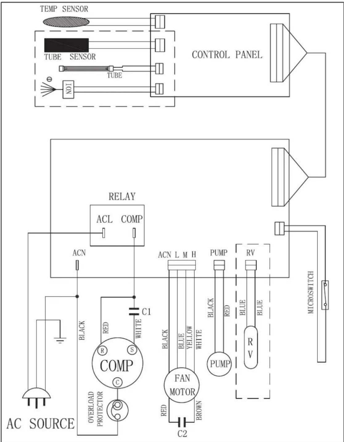
Wiring diagram PAC 3200 E A+

flowchart
graph TD
    A["AC SOURCE"] --> B["COMP"]
    B --> C["RELAY"]
    C --> D["ACL COMP"]
    D --> E["CONTROL PANEL"]
    E --> F["MICROSWITCH"]
    G["TUBE"] --> H["TUBE"]
    I["TEMP SENSOR"] --> J["TUBE"]
    K["TUBE"] --> L["TUBE"]
    M["ACN"] --> N["ACN L M H"]
    O["C1"] --> P["C2"]
    Q["BACK"] --> R["BLACK"]
    S["RED"] --> T["RED"]
    U["WHITE"] --> V["WHITE"]
    W["PUMP"] --> X["PUMP"]
    Y["RV"] --> Z["RV"]
    AA["BLUE"] --> AB["BLUE"]
    AC["WHITE"] --> AD["WHITE"]
    AE["BLACK"] --> AF["FAN MOTOR"]
    AG["BROWN"] --> AH["C2"]
PAC 4100 E
flowchart
graph TD
    A["AC SOURCE"] --> B["COMP"]
    B --> C["RELAY"]
    C --> D["ACL COMP"]
    D --> E["CONTROL PANEL"]
    E --> F["MICROSWITCH"]
    G["TUBE SENSOR"] --> H["TEMP SENSOR"]
    H --> I["TUBE"]
    I --> J["N01"]
    J --> K["NO1"]
    K --> L["CONTROL PANEL"]
    M["ACN"] --> N["RELAY"]
    O["C1"] --> P["RELAY"]
    Q["BACK"] --> R["RELAY"]
    S["C2"] --> T["RELAY"]
    U["R"] --> V["RELAY"]
    W["S"] --> X["RELAY"]
    Y["OVERLOAD PROTECTOR"] --> Z["RELAY"]
    AA["FAN MOTOR"] --> AB["RELAY"]
    AC["BLACK"] --> AD["RELAY"]
    AE["BLUE YELLOW"] --> AF["RELAY"]
    AG["BROWN"] --> AH["RELAY"]
    AI["PUMP"] --> AJ["RELAY"]
    AK["RV"] --> AL["RELAY"]
    AM["PUMP"] --> AN["RELAY"]
    AO["RV"] --> AP["RELAY"]
Spare parts drawing and list
PAC 3200 E A+
Note!
The position numbers of the spare parts differ from those describing the positions of other parts mentioned in this operating manual.

| No. | Spare part No. | Spare part No. | Spare part | ||||
| 101 | FRONT PANEL 136 ∅142 EXHAUST PIPE 302 NET | FOR AIR VENT | |||||
| 102 | REAR PANEL 137 A∅142 DAPTOR 303 CASTER | ||||||
| 103 | BASE PANEL 138 ∅142 COVER FOR ADAPTOR 305 MAIN | SUPPORTER | |||||
| 104 | SIDE PANEL 139 ∅142 SLIDE WINDOW KIT A 306 CAPACITOR CLIP | ||||||
| 105 | TOP PANEL 140 ∅142 SLIDE WINDOW KIT B 307 FAN BLADE FIXER | ||||||
| 106 | AIR VENT PANEL 141 ∅142 SLIDE WINDOW KIT C 309 SUPPORTER FOR THE PUMP MOTOR | ||||||
| 114 | HORIZONTAL LOUVER A 145 REMOTE CONTROL 801 CARTON BOX | ||||||
| 115 | HORIZONTAL LOUVER B 202 MOTOR 802 BOTTOM CASE | ||||||
| 116 | VERTICAL LOUVER A 203 PUMP MOTOR 810 NAMEPLATE | ||||||
| 117 | VERTICAL LOUVER B 204 MAIN P.C. BOARD 815 ACTIVE CARBON FILTER | ||||||
| 118 | SIDE FILTER FRAME 205 CONTROL P.C.BOARD 816 LABEL FOR Country-Of-Manufacture | ||||||
| 121 | LEFT HANDLE 206 MICRO SWITCH 817 RATING LABEL | ||||||
| 122 | RIGHT HANDLE 207 COMPRESSOR CAPACITOR 818 INSTRUCTION MANUAL (ONE LANGUAGE) | ||||||
| 134 | RUBBER STOPPER 210 MOTOR CAPACITOR | ||||||
| 135 | DRAIN KNOB 301 SAFETY NET BETWEEN TOP VOLUTE ANDLOWER VOLUTE | ||||||
PAC 4100 E Note!
The position numbers of the spare parts differ from those describing the positions of other parts mentioned in this operating manual.

| No. | Spare part No. | Spare part No. | Spare part | ||||
| 101 | FRONT PANEL 136 ∅142 EXHAUST PIPE 302 NET | FOR AIR VENT | |||||
| 102 | REAR PANEL 137 A∅142 DAPTOR 303 CASTER | ||||||
| 103 | BASE PANEL 138 ∅142 COVER FOR ADAPTOR 305 MAIN | SUPPORTER | |||||
| 104 | SIDE PANEL 139 ∅142 SLIDE WINDOW KIT A 306 CAPACITOR CLIP | ||||||
| 105 | TOP PANEL 140 ∅142 SLIDE WINDOW KIT B 307 FAN BLADE FIXER | ||||||
| 106 | AIR VENT PANEL 141 ∅142 SLIDE WINDOW KIT C 309 SUPPORTER FOR THE PUMP MOTOR | ||||||
| 114 | HORIZONTAL LOUVER A 145 REMOTE CONTROL 801 CARTON BOX | ||||||
| 115 | HORIZONTAL LOUVER B 202 MOTOR | 802 BOTTOM CASE | |||||
| 116 | VERTICAL LOUVER A 203 PUMP MOTOR 810 NAMEPLATE | ||||||
| 117 | VERTICAL LOUVER B 204 MAIN P.C. BOARD 815 ACTIVE CARBON FILTER | ||||||
| 118 | SIDE FILTER FRAME 205 CONTROL P.C.BOARD 816 LABEL FOR Country-Of-Manufacture | ||||||
| 121 | LEFT HANDLE 206 MICRD SWITCH 817 RATING LABEL | ||||||
| 122 | RIGHT HANDLE 207 COMPRESSOR CAPACITOR 818 INSTRUCTION MANUAL (ONE LANGUAGE) | ||||||
| 134 | RUBBER STOPPER 210 MOTOR CAPACITOR | ||||||
| 135 | DRAIN KNOB 301 SAFETY NET BETWEEN TOP VOLUTE ANDLOWER VOLUTE | ||||||
Disposal

In the European Union, electronic equipment must not be treated as domestic waste, but must be disposed of professionally in accordance with Directive 2002/96/EC of the European Parliament and of the Council of 27 January 2003 on waste electrical and electronic equipment (WEEE). At the end of its life, please dispose of this device according to the valid legal requirements.
The device uses an environmentally and ozone-neutral cooling agent (see Technical Data).
Dispose of the refrigerant appropriately and according to the national regulations.
Declaration of conformity
in accordance with the EU Low Voltage Directive 2014/35/EU and the EU Directive 2014/30/EU relating to electromagnetic compatibility.
Herewith, we declare that the device PAC 3200 E A+ / PAC 4100 E was developed, constructed and produced in compliance with the named EU directives.
Applied standards:
EN 60335-2-40:2003/A13:2012
EN 60335-1:2012/A11:2014
EN 62233:2008
The C€ marking is found on the rear of the device.
Manufacturer:
- table of contents
- Notes regarding the operating manual
- Symbols
- Hazardous electric current!
- Danger!
- Caution!
- Legal notice
- Warranty and liability
- Safety
- Read this manual carefully before starting or using the device. Always store the manual in the immediate vicinity of the device or its site of use!
- Intended use
- Improper use
- Personnel qualifications
- Residual risks
- Behaviour in the event of an emergency
- Information about the device
- Device description
- Transport and storage
- Transport
- Storage
- Assembly and installation
- Scope of delivery
- Unpacking the device
- Start-up
- Inserting the air filter
- Connecting the exhaust air hose
- Discharging exhaust air
- How to use the inserts
- Opening the ventilation flaps
- Connecting the power cable
- Operation
- Switching the device on
- Cooling
- Dehumidification
- Note:
- Ventilation
- Automatic operation
- Setting the timer
- Automatic switch-on
- Automatic switch-off
- Night mode
- Energy saving
- Remote control
- Shutdown
- Errors and faults
- The device does not start:
- The device works with reduced or no cooling capacity:
- The device is loud or vibrates:
- Condensate is leaking:
- The compressor does not start:
- The device gets very warm, is loud or loses power:
- The device does not respond to the infrared remote control:
- Your device still does not operate correctly after these checks?
- Error codes
- Activities required before starting maintenance
- Cleaning the housing
- Visual inspection of the inside of the device for dirt
- Cleaning the air filter
- Condensate discharge
- Refrigerant circuit
- Activities required after maintenance
- Spare parts drawing and list
- PAC 3200 E A+
- Note!
- PAC 4100 E Note!
- Disposal
- Declaration of conformity
Brand : TROTEC
Model : PAC 3200 E
Category : Air conditioner