
2404VLZ4 - Mixer MACKIE - Free user manual and instructions
Find the device manual for free 2404VLZ4 MACKIE in PDF.


| Product Type | Analog Mixing Console |
| Model | 2404VLZ4 |
| Brand | Mackie |
| Channels | 24 inputs (12 mono + 6 stereo) |
| Dimensions (W x D x H) | 19 x 18 x 5.5 inches |
| Weight | 22 lbs (10 kg) |
| Power Supply | Internal, 100-240 VAC, 50/60 Hz |
| Power Consumption | 60 W |
| Frequency Response | 20 Hz - 20 kHz ±0.5 dB |
| EQ per Channel | 3-band (Low, Mid, High) with swept mid |
| Low-Cut Filter | 75 Hz, 18 dB/octave |
| Aux Sends | 4 (2 pre, 2 post) |
| Subgroups | 4 |
| Main Output | XLR balanced, TRS balanced |
| Phantom Power | 48V (global switch) |
| Construction | Steel chassis, durable knobs |
| Maintenance & Cleaning | Wipe with dry, lint-free cloth; avoid liquids |
| Safety Precautions | Disconnect power before cleaning; use only provided power cord |
| Spare Parts & Reparability | Contact Mackie authorized service centers; module design facilitates repair |
| Intended Use | Live sound reinforcement, recording, fixed installations |
Frequently Asked Questions - 2404VLZ4 MACKIE
User questions about 2404VLZ4 MACKIE
0 question about this device. Answer the ones you know or ask your own.
Ask a new question about this device
Download the instructions for your Mixer in PDF format for free! Find your manual 2404VLZ4 - MACKIE and take your electronic device back in hand. On this page are published all the documents necessary for the use of your device. 2404VLZ4 by MACKIE.
USER MANUAL 2404VLZ4 MACKIE
Important Safety Instructions
- Read these instructions.
- Keep these instructions.
- Heed all warnings.
- Follow all instructions.
- Do not use this apparatus near water.
- Clean only with a dry cloth.
- Do not block any ventilation openings. Install in accordance with the manufacturer's instructions.
- Do not install near any heat sources such as radiators, heat registers, stoves, or other apparatus (including amplifiers) that produce heat.
- Do not defeat the safety purpose of the polarized or grounding-type plug. A polarized plug has two blades with one wider than the other. A grounding-type plug has two blades and a third grounding prong. The wide blade or the third prong are provided for your safety. If the provided plug does not fit into your outlet, consult an electrician for replacement of the obsolete outlet.
- Protect the power cord from being walked on or pinched particularly at plugs, convenience receptacles, and the point where they exit from the apparatus.
- Only use attachments/accessories specified by the manufacturer.
- Use only with a cart, stand, tripod, bracket, or table specified by the manufacturer, or sold with the apparatus. When a cart is used, use caution when moving the cart/apparatus combination to avoid injury from tip-over.
- Unplug this apparatus during lightning storms or when unused for long periods of time.
- Refer all servicing to qualified service personnel. Servicing is required when the apparatus has been damaged in any way, such as power-supply cord or plug is damaged, liquid has been spilled or objects have fallen into the apparatus, the apparatus has been exposed to rain or moisture, does not operate normally, or has been dropped.
- This apparatus shall not be exposed to dripping or splashing, and no object filled with liquids, such as vases or beer glasses, shall be placed on the apparatus.
- Do not overload wall outlets and extension cords as this can result in a risk of fire or electric shock.


The lightning flash with arrowhead symbol within an equilateral triangle is intended to alert the user to the presence of uninsulated "dangerous voltage" within the product's enclosure, that may be of sufficient magnitude to constitute a risk of electric shock to persons.
The exclamation point within an equilateral triangle is intended to alert the user of the presence of important operating and maintenance (servicing) instructions in the literature accompanying the appliance.
-
This apparatus has been designed with Class-I construction and must be connected to a mains socket outlet with a protective earthing connection (the third grounding prong).
-
This apparatus has been equipped with a rocker-style AC mains power switch. This switch is located on the rear panel and should remain readily accessible to the user.
-
The MAINS plug or an appliance coupler is used as the disconnect device, so the disconnect device shall remain readily operable.
-
NOTE: This equipment has been tested and found to comply with the limits for a Class B digital device, pursuant to part 15 of the FCC Rules. These limits are designed to provide reasonable protection against harmful interference in a residential installation. This equipment generates, uses, and can radiate radio frequency energy and, if not installed and used in accordance with the instructions, may cause harmful interference to radio communications. However, there is no guarantee that interference will not occur in a particular installation. If this equipment does cause harmful interference to radio or television reception, which can be determined by turning the equipment off and on, the user is encouraged to try to correct the interference by one or more of the following measures:
-
Reorient or relocate the receiving antenna.
- Increase the separation between the equipment and the receiver.
- Connect the equipment into an outlet on a circuit different from that to which the receiver is connected.
- Consult the dealer or an experienced radio/TV technician for help. CAUTION: Changes or modifications to this device not expressly approved by LOUD Technologies Inc. could void the user's authority to operate the equipment under FCC rules.
- This apparatus does not exceed the Class A/Class B (whichever is applicable) limits for radio noise emissions from digital apparatus as set out in the radio interference regulations of the Canadian Department of Communications.
- Exposure to extremely high noise levels may cause permanent hearing loss. Individuals vary considerably in susceptibility to noise-induced hearing loss, but nearly everyone will lose some hearing if exposed to sufficiently intense noise for a period of time. The U.S. Government's Occupational Safety and Health Administration (OSHA) has specified the permissible noise level exposures shown in the following chart.
According to OSHA, any exposure in excess of these permissible limits could result in some hearing loss. To ensure against potentially dangerous exposure to high sound pressure levels, it is recommended that all persons exposed to equipment capable of producing high sound pressure levels use hearing protectors while the equipment is in operation. Ear plugs or protectors in the ear canals or over the ears must be worn when operating the equipment in order to prevent permanent hearing loss if exposure is in excess of the limits set forth here:
| Duration, per day in hours | Sound Level dBA, Slow Response | Typical Example |
| 8 | 90 | Duo in small club |
| 6 | 92 | |
| 4 | 95 | Subway Train |
| 3 | 97 | |
| 2 | 100 | Very loud classical music |
| 1.5 | 102 | |
| 1 | 105 | Greg and Ben screaming at Troy about deadlines |
| 0.5 | 110 | |
| 0.25 or less | 115 | Loudest parts at a rock concert |
Table of Contents
Introduction......4
Getting Started ....5
Zero the Controls 5
Connections....5
Set the Levels 5
Instant Mixing 5
Hookup Diagrams 6
Onyx 4•Bus Features ....10
Mono Channel Strips....10
Stereo Channel Strips 13
Matrix, Compressor, and Metering Section....15
Phones/Monitor, Solo, Mono, and Talkback Section 17
Auxiliary Section 18
Group Section 20
Rear Panel 21
Appendix A: Service Information 25
Troubleshooting 25
Repair 26
Appendix B: Connections ......27
Appendix C: Technical Info 30
Onyx 4•Bus Specifications....30
Onyx 4•Bus Dimensions 31
Onyx 4•Bus Block Diagram....32
Onyx 4•Bus Gain Structure Diagram 34
Onyx 4•Bus Limited Warranty ....35
Don't forget to visit our website at www.mackie.com for more information about this and other Mackie products.
Introduction
Thank you for choosing a Mackie Onyx 4•Bus professional live mixing console. The Onyx 4•Bus mixers feature all-new analog circuitry and the latest technologies for live sound reinforcement in a durable, road-worthy package.
The Onyx 4•Bus mixing consoles replace the legendary SR24•4 and SR32•4 VLZ PRO mixers. The new Onyx versions of these mixers maintain the same physical size, channel count and features of the originals, while adding a variety of new and improved features.
The Onyx 4•Bus consoles are equipped with our new premium precision-engineered, studio-grade Onyx mic preamps. Mackie is renowned for the high-quality mic preamps used in our mixers, and the Onyx mic pre's are better than ever, with specifications rivaling expensive stand-alone boutique mic preamplifiers.
Each mono channel strip features an individual phantom power switch, low-cut filter, mic input pad, pre-EQ channel insert, and an all new four-band EQ design with sweepable mids and EQ bypass switch.
All mono channels have six Aux sends, Pan, Mute, PFL Solo, 100 mm Fader, Group and Main Mix assign, and four signal-level indicators. In addition, balanced direct outputs are provided on DB-25 connectors (eight channels per connector) for multitrack recording.
The master section features two Stereo Returns, six Master Aux sends, four Group Masters, a 6x2 Matrix, a Phones/Monitor section, and a Talkback section with routing switches that allow you to communicate through the Aux Sends and the L/R mix.
A new feature with the Onyx 4•Bus mixers is an analog stereo compressor/limiter that can be inserted at the output of the L/R main mix, or the Group 1/2 or 3/4 outputs.
Please write your serial number here for future reference (i.e., insurance claims, tech support, return authorization, etc.)
Purchased at:
Date of purchase:
HOW TO USE THIS MANUAL
We know that many of you can't wait to get your new mixing console hooked up, and you're probably not going to read the manual first (sigh!). So the next section is a Quick-Start Guide to help you get the mixer set up fast so you can start using it right away. Right after that are the ever popular hook-up diagrams that show typical mixer setups for live sound, recording and mixdown.
Then, when you have time, read the Features Description section. This describes every knob, button, and connection point on the Onyx 4•Bus, roughly following the signal flow through the mixer.
Throughout this section you'll find illustrations with each feature numbered. If you want to know more about a feature, simply locate it on the appropriate illustration, notice the number attached to it, and find that number in the nearby paragraphs.

This icon marks information that is critically important or unique to the Onyx 4•Bus. For your own good, read them and remember them. They will be on the final test.

This icon leads you to in-depth explanations of features and practical tips. While not mandatory, they usually have some valuable nugget of information.
A PLUG FOR THE CONNECTOR SECTION
Appendix B is a section on connectors: XLR connectors, balanced connectors, unbalanced connectors, and special hybrid connectors.
More resources on our website at www.mackie.com.
Click on Support to find answers to many of your questions. The FAQ (Frequently Asked Questions) section is filled with answers to many of the questions our Technical Support staff has fielded over the years.
Check out the glossary for explanations of many of the pro-audio terms used in our manuals.
Getting Started
READ THIS PAGE!!

Even if you're one of those people who never read manuals, all we ask is that you read this page now before you begin using the Onyx 4•Bus. You'll be glad you did!
Zero the Controls
- Turn down the channel GAIN, AUX, and Fader controls, and center the channel EQ and PAN controls.
- Set all push button switches to their "out" positions.
- In the Master section, turn all the rotary knobs "down," the switches "out," and the faders down.
- Turn the POWER switch off.
Connections
If you already know how you want to connect the Onyx 4•Bus mixing console, go ahead and connect the inputs and outputs the way you want them. If you just want to get sound through the mixer, follow these steps:
- Plug a microphone or other signal source into channel 1's MIC or LINE input [73/74].
- Plug in the detachable linecord, connect it to an AC outlet, and turn on the Onyx 4•Bus' POWER switch [90].
- Connect cables from the Onyx 4•Bus' MAIN OUTS [82] (XLR connectors or 1/4" TRS connectors on the rear panel) to your amplifier or active speakers.
- Hook up speakers to the amp and turn it on. If the amplifier has level controls, set them however the manufacturer recommends (usually all the way up).
Set the Levels
To set the channel GAIN controls, it's not even necessary to hear what you're doing at the outputs of the mixer. If you want to listen while you work, plug headphones into the PHONES jack [46] on the front panel, then set the PHONES knob [47] about one-quarter of the way up and the SOLO LEVEL [49] about halfway up.
The following steps must be performed one channel at a time.
- Push in the channel's PFL [18] solo switch.
- Play something into the selected input. This could be an instrument, a singing or speaking voice, or a line input such as a CD player or tape recorder
output. Be sure that the volume of the input source is the same as it would be during normal use. If it isn't, you might have to readjust these levels during the middle of the set.
- Adjust the channel's GAIN [4] control so that the LEDs on the Left MAIN MIX meter stay around "0" and never go higher than "+10."
- If you'd like to apply some EQ, do so now and return to step 3. Remember to push in the EQ IN/OUT [11] switch or the EQ controls won't do anything.
- Disengage that channel's PFL solo switch.
- Repeat for each channel.
Instant Mixing
- Leave the microphone plugged into channel 1 and connect a keyboard, guitar or other instrument to channel 2. Be sure to "Set the Levels" for channel 2 as described above.
- To get sound out of the speakers, push in the MAIN MIX assign switch [17] next to the faders on channels 1 and 2, turn up channel 1 and 2 faders [15] to the “U” mark and slowly turn up the MAIN MIX [72] fader to a comfortable listening level.
- Sing and play. You're a star! Adjust the faders for channels 1 and 2 to bring your voice and your instrument up and down to create your own mix.
Other Nuggets of Wisdom
- For optimum sonic performance, the channel and MAIN MIX faders should be set near the "U" (unity gain) markings.
- Always turn the MAIN MIX faders, GROUP faders, and MONITOR knob down before making connections to and from your Onyx 4•Bus.
- When you shut down your equipment, turn off the amplifiers first. When powering up, turn on the amplifiers last.
- Never listen to loud music for prolonged periods. Please see the Safety Instructions on page 2 for information on hearing protection.
- Save the shipping box! You may need it someday, and you don't want to have to pay for another one.
That's it for the "Getting Started" section. Next comes the "Hookup" section that shows you some typical ways that you might use the Onyx 4•Bus in real applications. After that, take the grand tour of the mixer, with descriptions of every knob, button, input, and output. We encourage you to take the time to read all of the feature descriptions, but at least you know it's there if you have any questions.
Hookup Diagrams
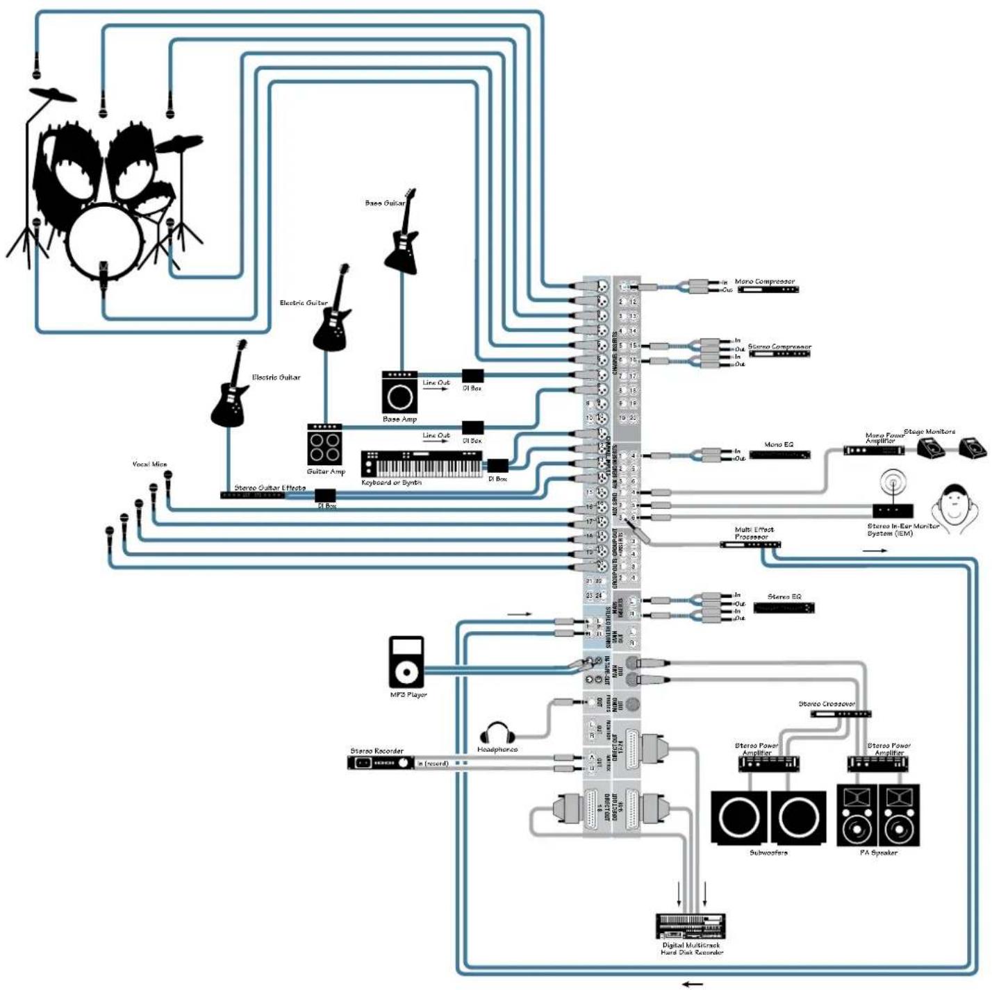
This hookup diagram demonstrates how you can make a live multitrack recording using the DIRECT OUTs. The DIRECT OUTs provide an analog balanced direct output for each channel, pre-EQ. The Matrix outputs are used to create a stereo recording for backup.
Aux Send 4 is used for stage monitors, and a graphic EQ is connected to the Aux 4 Insert jack, serving as a dedicated in-line EQ for the monitors. Aux Sends 5 and 6 are used to drive a stereo IEM system. Aux Send 3 drives a stereo effects processor, whose stereo signal is returned via the Stereo Returns jacks.
flowchart
graph TD
    A["Drums"] --> B["Base Guitar"]
    A --> C["Electric Guitar"]
    A --> D["Guitar Amp"]
    A --> E["Handheld Piano"]
    A --> F["Handheld Piano"]
    A --> G["Handheld Piano"]
    A --> H["Handheld Piano"]
    A --> I["Handheld Piano"]
    A --> J["Handheld Piano"]
    A --> K["Handheld Piano"]
    A --> L["Handheld Piano"]
    A --> M["Handheld Piano"]
    A --> N["Handheld Piano"]
    A --> O["Handheld Piano"]
    A --> P["Handheld Piano"]
    A --> Q["Handheld Piano"]
    A --> R["Handheld Piano"]
    A --> S["Handheld Piano"]
    A --> T["Handheld Piano"]
    A --> U["Handheld Piano"]
    A --> V["Handheld Piano"]
    A --> W["Handheld Piano"]
    A --> X["Handheld Piano"]
    A --> Y["Handheld Piano"]
    A --> Z["Handheld Piano"]
    A --> AA["Handheld Piano"]
    A --> AB["Handheld Piano"]
    A --> AC["Handheld Piano"]
    A --> AD["Handheld Piano"]
    A --> AE["Handheld Piano"]
    A --> AF["Handheld Piano"]
    A --> AG["Handheld Piano"]
    A --> AH["Handheld Piano"]
    A --> AI["Handheld Piano"]
    A --> AJ["Handheld Piano"]
    A --> AK["Handheld Piano"]
    A --> AL["Handheld Piano"]
    A --> AM["Handheld Piano"]
    A --> AN["Handheld Piano"]
    A --> AO["Handheld Piano"]
    A --> AP["Handheld Piano"]
    A --> AQ["Handheld Piano"]
    A --> AR["Handheld Piano"]
    A --> AS["Handheld Piano"]
    A --> AT["Handheld Piano"]
    A --> AU["Handheld Piano"]
    A --> AV["Handheld Piano"]
    A --> AW["Handheld Piano"]
    A --> AX["Handheld Piano"]
    A --> AY["Handheld Piano"]
    A --> AZ["Handheld Piano"]
    A --> BA["Handheld Piano"]
    A --> BB["Handheld Piano"]
    A --> BC["Handheld Piano"]
    A --> BD["Handheld Piano"]
    A --> BE["Handheld Piano"]
    A --> BF["Handheld Piano"]
    A --> BG["Handheld Piano"]
    A --> BH["Handheld Piano"]
    A --> BI["Handheld Piano"]
    A --> BJ["Handheld Piano"]
    A --> BK["Handheld Piano"]
    A --> BL["Handheld Piano"]
    A --> BM["Handheld Piano"]
    A --> BN["Handheld Piano"]
    A --> BO["Handheld Piano"]
    A --> BP["Handheld Piano"]
    A --> BQ["Handheld Piano"]
    A --> BR["Handheld Piano"]
    A --> BS["Handheld Piano"]
    A --> BT["Handheld Piano"]
    A --> BU["Handheld Piano"]
    A --> BV["Handheld Piano"]
    A --> BW["Handheld Piano"]
    A --> BX["Handheld Piano"]
    A --> BY["Handheld Piano"]
    A --> BZ["Handheld Piano"]
    A --> CA["Handheld Piano"]
    A --> CB["Handheld Piano"]
    A --> CC["Handheld Piano"]
    A --> CD["Handheld Piano"]
    A --> CE["Handheld Piano"]
    A --> CF["Handheld Piano"]
    A --> CG["Handheld Piano"]
    A --> CH["Handheld Piano"]
    A --> CI["Handheld Piano"]
    A --> CJ["Handheld Piano"]
    A --> CK["Handheld Piano"]
    A --> CL["Handheld Piano"]
    A --> CM["Handheld Piano"]
    A --> CN["Handheld Piano"]
    A --> CO["Handheld Piano"]
    A --> CP["Handheld Piano"]
    A --> CQ["Handheld Piano"]
    A --> CR["Handheld Piano"]
    A --> CS["Handheld Piano"]
    A --> CT["Handheld Piano"]
    A --> CU["Handheld Piano"]
    A --> CV["Handheld Piano"]
    A --> CW["Handheld Piano"]
    A --> CX["Handheld Piano"]
    A --> CY["Handheld Piano"]
    A --> CZ["Handheld Piano"]
    A --> DA["Handheld Piano"]
    A --> DB["Handheld Piano"]
    A --> DC["Handheld Piano"]
    A --> DD["Handheld Piano"]
    A --> DE["Handheld Piano"]
    A --> DF["Handheld Piano"]
    A --> DG["Handheld Piano"]
    A --> DH["Handheld Piano"]
    A --> DI["Handheld Piano"]
    A --> DJ["Handheld Piano"]
    A --> DK["Handheld Piano"]
    A --> DL["Handheld Piano"]
    A --> DV["Handheld Piano"]
    A --> DW["Handheld Piano"]
    A --> DXA["Handheld Piano"]
    A --> DXB["Handheld Piano"]
    A --> DXC["Handheld Piano"]
    A --> DXD[X/A/DC/DC/DC/DC/DC/DC/DC/DC/DC/DC/DC/DC/DC/DC/DC/DC/DC/DC/DC/DC/DC/DC/DC/DC/DC/DC/DC/DC/DC/DC/DC/DC/DC/DC/DC/DC/DC/DC/DC/DC/DC/DC/DC/DC/DC/DC/DC/DC/DC/DC/ DC/DC/DC/DC/DC/DC/DC/DC/DC/DC/DC/DC/DC/DC/DC/DC/DC/DC/DC/DC/DC/DC/DC/DC/DC/DC/DC/DC/DC/DC/DC/DC/DC/DC/DC/DC/DC/DC/DC/DC/DC/DC/DC/DC/DC/DC/DC/DC/DC/DC/NCI / DC / DC / DC / DC / DC / DC / DC / DC / DC / DC / DC / DC / DC / DC / DC / DC / DC / DC / DC / DC / DC / DC / DC / DC / DC / DC / DC / DC / DC / DC / DC / DC / DC / DC / DC / DC / DC / DC / DC / DC / DC / DC / DC / DC / DC / DC / DC / DC / DC / DC / AC |

    subgraph Channel
        direction TB
        direction LR
        direction UA
        direction VB
        direction Y
        direction Z
        direction AA
        direction AB
        direction AC
        direction AD
        direction AE
        direction AF
        direction AG
        direction AH
        direction AI
        direction AJ
        direction AK
        direction AL
        direction AM
        direction AN
        direction AO
        direction AP
        direction AQ
        direction AR
        direction AS
        direction AT
        direction AU
        direction AV
        direction AW
        direction AX
        direction AZ
        direction BA
        direction BB
        direction BC
        direction BD
        direction BE
        direction BF
        direction BG
        direction BH
        direction BI
        direction BJ
        direction BK
        direction BL
        direction BM
        direction BN
        direction BO
        direction BP
        direction BP1
        direction BP2
        direction BP3
        direction BP4
        direction BP5
        direction BP6
        direction BP7
        direction BP8
        direction BP9
        direction BP10
        direction BP11
        direction BP12
        direction BP13
        direction BP14
        direction BP15
        direction BP16
        direction BP17
        direction BP18
        direction BP19
        direction BP20
        direction BP21
        direction BP22
        direction BP23
        direction BP24
        direction BP25
        direction BP26
        direction BP27
        direction BP28
        direction BP29
        direction BP30
        direction BP31
        direction BP32
        direction BP33
        direction BP34
        direction BP35
        direction BP36
        direction BP37
        direction BP38
        direction BP39
        direction BP40
        direction BP41
        direction BP42
        direction BP43
        direction BP44
        direction BP45
        direction BP46
        direction BP47
        direction BP48
        direction BP49
        direction BP50
        direction BP51
        direction BP52
        direction BP53
        direction BP54
        direction BP55
        direction BP56
        direction BP57
        direction BP58
        direction BP59
        direction BP60
        direction BP61
        direction BP62
        direction BP63
        direction BP64
        direction BP65
        direction BP66
        direction BP67
        direction BP68
        direction BP69
        direction BP70
        direction BP71
        direction BP72
        direction BP73
        direction BP74
        direction BP75
        direction BP76
        direction BP77
        direction BP78
        direction BP79
        direction BP80
        directional arrows indicate signal paths from the source to the output of the output of the output of the output of the output of the output of the output of the output of the output of the output of the output of the output of the output of the output of the output of the output of the output of the output of the output of the output of the output of the output of the output of the output of the output of the output of the output of the output of the output of the output of the output of the output of the output of the output of 1.0 (in dB) (out dB) (in dB) (out dB) (out dB) (out dB) (out dB) (out dB) (out dB) (out dB) (out dB) (out dB) (out dB) (out dB) (out dB) (out dB) (out dB) (out dB) (out dB) (out dB) (out dB) (out dB) (out dB) (out dB) (out dB) (out dB) (out dB) (out dB) (OUT dB)
            |
            |
            |
            |
            |
            |
            |
            |
            |
            |
            |
            |
            |
            |
            |
            |
            |
            |
            |
            |
            |
            |
            |
            |
            |
            |
            |
            |
            |
            |
            |
            |
            |
            |
             |
              |
              |
              |
              |
              |
              |
              |
              |
              |
              |
              |
              |
              |
              |
              |
              |
              |
              |
              |
              |
              |
              |
              |
              |
              |
              |
              |
              |
              |
              |
              |
              |
              |
              |
              |
              |
| Micro-Sensor Interface |
| MF2 Player Interface |
| STOER Recorder Interface |
| Headphones Interface |
| Digital Multicrack Hard Disk Recorder Interface |
| Stereo Power Amplifier Interface |
| Stereo Power Amplifier Interface |
| Subwoofera Interface |
| PA Speaker Interface |
| Stereo Power Amplifier Interface |
| Stereo Power Amplifier Interface |
| Stereo Power Amplifier Interface |
| Stereo Power Amplifier Interface |
| Stereo Power Amplifier Interface |
| Stereo Power Amplifier Interface |
| Stereo Power Amplifier Interface |
| Stereo Power Amplifier Interface |
| Stereo Power Amplifier Interface |
| Stereo Power Amplifier Interface |
| Stereo Power Amplifier Interface |
| Stereo Power Amplifier Interface |
| Stereo Power Amplifier Interface |
| Stereo Power Amplifier Interface |
| Stereo Power Amplifier Interface (Symbol: Square, Circle, Triangle, etc.) |
| Stereo Power Amplifier Interface (Symbol: Square, Circle, Triangle, etc.) |
| Stereo Power Amplifier Interface (Symbol: Square, Circle, Triangle, etc.) |
| Stereo Power Amplifier Interface (Symbol: Square, Circle, Triangle, etc.) |
| Stereo Power Amplifier Interface (Symbol: Square, Circle, Triangle, etc.) |
| Stereo Power Amplifier Interface (Symbol: Square, Circle, Triangle, etc.) |
| Stereo Power Amplifier Interface (Symbol : Square, Circle, Triangle, etc., etc., etc., out of 1.0) |
| Stereo Power Amplifier Interface (Symbol : Square, Circle, Triangle, etc., etc., etc., out of 1.0) |
| Stereo Power Amplifier Interface (Symbol : Square, Circle, Triangle, etc., etc., etc., out of 1.0) |
| Stereo Power Amplifier Interface (Symbol : Square, Circle, Triangle, etc., etc., etc., out of 1.0) |
| Stereo Power Amplifier Interface (Symbol : Square, Circles, Circles, Circles, Circles, Circles, Circles, Circles, Circles, Circles, Circles, Circles, Circles, Circles, Circles, Circles, Circles, Circles, Circles, Circles, Circles, Circles, Circles, Circles, Circles, Circles, Circles, Circles, Circles, Circles, Circles, Circles, Circles, Circles, Circles & Circles & Circles & Circles & Circles & Circles & Circles & Circles & Circles & Circles & Circles & Circles & Circles & Circles & Circles & Circles & Circles & Circles & Circles & Circles & Circles & Circles & Circles & Circles & Circles & Circles & Circles & Circles & Circles & Circles & Circles & Circles & Circles & Circles & ○ (in dB) (out dB) (out dB) (out dB) (out dB) (out dB) (out dB) (out dB) (out dB) (out dB) (out dB) (out dB) (out dB) (out dB) (out dB) (out dB) (out dB) (out dB) (out dB) (out dB) (out dB) (out dB) (out dB) (out dB) (out dB)
Onyx 24·4 Live Club Mix and Multitrack Recording
flowchart
graph TD
    A["Dr. Bass"] --> B["Base Guitar"]
    A --> C["Electric Guitar"]
    A --> D["Electrical Guitar"]
    A --> E["Base Amp"]
    A --> F["Di Box"]
    A --> G["Line Out"]
    A --> H["Di Box"]
    A --> I["Di Box"]
    J["Dr. Bass"] --> K["Di Box"]
    L["Electric Guitar"] --> M["Base Amp"]
    L --> N["Di Box"]
    O["Electrical Guitar"] --> P["Di Box"]
    Q["Electrical Guitar"] --> R["Di Box"]
    S["Electrical Guitar"] --> T["Di Box"]
    U["Dr. Bass"] --> V["Di Box"]
    W["Electric Guitar"] --> X["Di Box"]
    Y["Electrical Guitar"] --> Z["Di Box"]
    AA["Vocal Mics"] --> AB["Stereo Guitar Effects"]
    AC["Liezen WedgeTaliback MilkXono Power Amplifier"] --> AD["Di Box"]
    AE["Liezen WedgeTaliback MilkXono Power Amplifier"] --> AF["Di Box"]
    AG["Di Box"] --> AH["Di Box"]
    AI["Di Box"] --> AJ["Di Box"]
    AK["Di Box"] --> AL["Di Box"]
    AM["Di Box"] --> AN["Di Box"]
    AO["Di Box"] --> AP["Di Box"]
    AQ["Di Box"] --> AR["Di Box"]
    AS["Di Box"] --> AT["Di Box"]
    AU["Di Box"] --> AV["Di Box"]
    AW["Di Box"] --> AX["Di Box"]
    AY["Di Box"] --> AZ["Di Box"]
    BA["Di Box"] --> BB["Di Box"]
    BC["Di Box"] --> BD["Di Box"]
    BE["Di Box"] --> BF["Di Box"]
    BG["Di Box"] --> BH["Di Box"]
    BI["Di Box"] --> BJ["Di Box"]
    BK["Di Box"] --> BL["Di Box"]
    BM["Di Box"] --> BN["Di Box"]
    BO["Di Box"] --> BP["Di Box"]
    BQ["Di Box"] --> BR["Di Box"]
    BS["Mono Compressor"] --> BT["Mono Compressor"]
    BU["Stereo Compressor"] --> BV["Stereo Compressor"]
    BW["Busco Compressor"] --> BX["Busco Compressor"]
    BY["Stereo Compressor"] --> BZ["Stereo Compressor"]
    CA["Stereo Compressor"] --> CB["Stereo Compressor"]
    CC["Stereo Compressor"] --> CD["Stereo Compressor"]
    CE["Stereo Compressor"] --> CF["Stereo Compressor"]
    DG["Stereo Compressor"] --> DH["Stereo Compressor"]
    DI["Stereo Compressor"] --> DJ["Stereo Compressor"]
    DK["Stereo Compressor"] --> DL["Stereo Compressor"]
    DM["Stereo Compressor"] --> DE["Stereo Compressor"]
    DF["Stereo Compressor"] --> DG
    DG --> DG0["Stereo Compressor"]
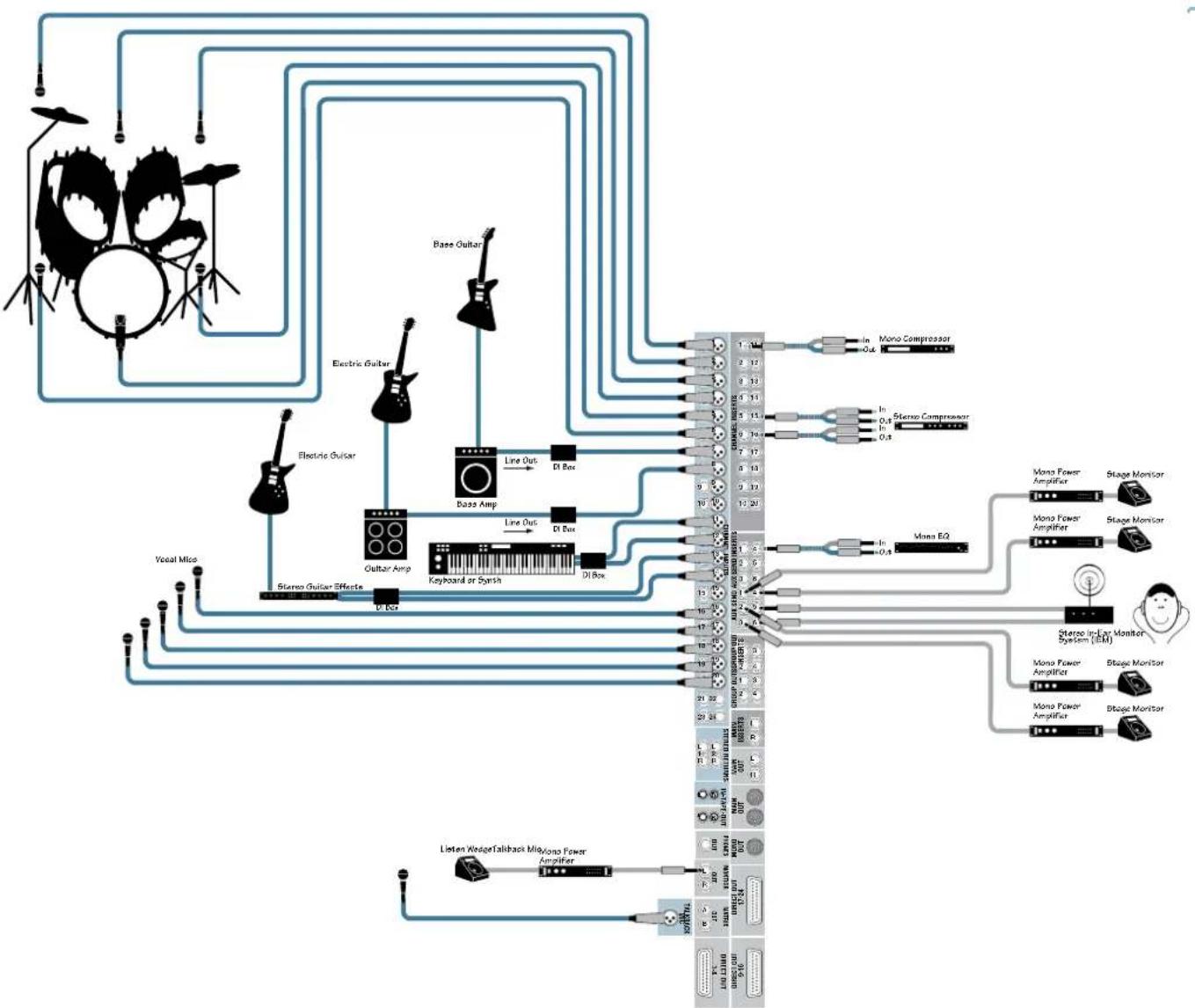
This drawing shows the flexibility of the Onyx 4•Bus for creating different monitor mixes. Auxes 1-4 provide separate monitor mixes for four floor wedges. Auxes 5-6 provide a stereo monitor mix for an in-ear monitor (IEM). The Aux Inserts can be used for in-line graphic EQ for each monitor send. A listen wedge is connected to the Monitor Out, allowing you to solo and listen to each monitor mix. The Talkback Mic lets you talk to the talent through the monitors (Aux Sends).
Onyx 24·4 Stage Monitor Mix

flowchart
graph TD
    A["Drum Microphones"] --> B["DAW (or Laptop)"]
    B --> C["Analog Audio Interface"]
    C --> D["Audio VIO for Workstation"]
    D --> E["To Desktop or Laptop Computer"]
    E --> F["Headphone for Studio"]
    C --> G["Line Out DI Box"]
    C --> H["Line Out DI Box"]
    C --> I["Line Out DI Box"]
    C --> J["Line Out DI Box"]
    C --> K["Line Out DI Box"]
    C --> L["Line Out DI Box"]
    C --> M["Line Out DI Box"]
    C --> N["Line Out DI Box"]
    C --> O["Line Out DI Box"]
    C --> P["Line Out DI Box"]
    C --> Q["Line Out DI Box"]
    C --> R["Line Out DI Box"]
    C --> S["Line Out DI Box"]
    C --> T["Line Out DI Box"]
    C --> U["Line Out DI Box"]
    C --> V["Line Out DI Box"]
    C --> W["Line Out DI Box"]
    C --> X["Line Out DI Box"]
    C --> Y["Line Out DI Box"]
    C --> Z["Line Out DI Box"]
    C --> AA["Line Out DI Box"]
    C --> AB["Line Out DI Box"]
    C --> AC["Line Out DI Box"]
    C --> AD["Line Out DI Box"]
    C --> AE["Line Out DI Box"]
    C --> AF["Line Out DI Box"]
    C --> AG["Line Out DI Box"]
    C --> AH["Line Out DI Box"]
    C --> AI["Line Out DI Box"]
    C --> AJ["Line Out DI Box"]
    C --> AK["Line Out DI Box"]
    C --> AL["Line Out DI Box"]
    C --> AM["Line Out DI Box"]
    C --> AN["Line Out DI Box"]
    C --> AO["Line Out DI Box"]
    C --> AP["Line Out DI Box"]
    C --> AQ["Line Out DI Box"]
    C --> AR["Line Out DI Box"]
    C --> AS["Line Out DI Box"]
    C --> AT["Line Out DI Box"]
    C --> AU["Line Out DI Box"]
    C --> AV["Line Out DI Box"]
    C --> AW["Line Out DI Box"]
    C --> AX["Line Out DI Box"]
    C --> AY["Line Out DI Box"]
    C --> AZ["Line Out DI Box"]
    C --> BA["Line Out DI Box"]
    C --> BB["Line Out DI Box"]
    C --> BC["Line Out DI Box"]
    C --> BD["Line Out DI Box"]
    C --> BE["Line Out DI Box"]
    C --> BF["Line Out DI Box"]
    C --> BG["Line Out DI Box"]
    C --> BH["Line Out DI Box"]
    C --> BI["Line Out DI Box"]
    C --> BJ["Line Out DI Box"]
    C --> BK["Line Out DI Box"]
    C --> BL["Line Out DI Box"]
    C --> BM["Line Out DI Box"]
    C --> BN["Line Out DI Box"]
    C --> BO["Line Out DI Box"]
    C --> BP["Line Out DI Box"]
    C --> BQ["Line Out DI Box"]
    C --> BR["Line Out DI Box"]
    C --> BS["Line Out DI Box"]
    C --> BT["Line Out DI Box"]
    C --> BU["Line Out DI Box"]
    C --> BV["Line Out DI Box"]
    C --> BW["Line Out DI Box"]
    C --> BX["Line Out DI Box"]
    C --> BY["Line Out DI Box"]
    C --> BZ["Line Out DI Box"]
In this hookup diagram, the Direct Outs for channels 9-24 are connected to the analog audio interface for your DAW or laptop for tracking. The drum microphones are subgrouped to Groups 1-4 and routed to the analog audio interface for recording.
A 2-track return is provided by the DAW (or laptop) to the Stereo Returns on the Onyx 24•4 for playback of the master mix.
Auxes 5-6 provide a stereo monitor mix for a headphone distribution amplifier (Aux 5-6 Inserts are connected to a stereo graphic EQ to provide equalization for the headphone mixes).
Onyx 24·4 Computer Recording

flowchart
graph TD
    A["Drums"] --> B["Electric Guitar"]
    A --> C["Bass Guitar"]
    A --> D["Guitar Amp"]
    A --> E["Keyboard or Dyrith"]
    A --> F["Stereo Guitar Effect"]
    A --> G["Audio Mask"]
    A --> H["Stereo Recorder"]
    A --> I["Headphones"]
    A --> J["Digital Multibreak Hard Slek Recorder"]
    B --> K["Line Out"]
    B --> L["D: Box"]
    C --> M["Line Out"]
    C --> N["D: Box"]
    D --> O["Line Out"]
    D --> P["D: Box"]
    E --> Q["Line Out"]
    E --> R["D: Box"]
    F --> S["Line Out"]
    F --> T["D: Box"]
    G --> U["Line Out"]
    G --> V["D: Box"]
    H --> W["Line Out"]
    H --> X["D: Box"]
    I --> Y["Line Out"]
    I --> Z["D: Box"]
    J --> AA["Line Out"]
    J --> AB["D: Box"]
    K --> AC["Multi-Panel Display"]
    L --> AC
    M --> AC
    N --> AC
    O --> AC
    P --> AC
    Q --> AC
    R --> AC
    S --> AC
    T --> AC
    U --> AC
    V --> AC
    W --> AC
    X --> AC
    Y --> AC
    Z --> AC
    AA --> AD["Power Amp Mono Mode"]
    AA --> AE["Power Amp Mono Mode"]
    AA --> AF["Power Amp Mono Mode"]
    AA --> AG["Front FL PA Speaker"]
    AA --> AH["Left FA Speaker"]
    AA --> AI["Right FA Speaker"]
    AA --> AJ["Power Amp Mono Mode"]
    AA --> AK["Subwoofer"]
In a House of Worship application, the Onyx 4•Bus provides plenty of Aux Sends for stage monitors, stereo in-ear monitoring, and assistive listening systems. The MONO output is used to provide front-fill for the first few rows not covered by the main PA speakers. A stereo graphic EQ is connected to the Main Inserts (the built-in compressor/limiter provides system limiting for the Main Mix). Aux 6 is used as a subwoofer feed (a low-pass filter is built in to either the power amplifier or subwoofer). The Matrix A and B outputs provide additional custom mixes for the balcony and the nursery.
Onyx 24·4 House of Worship
Onyx 4•Bus Features
Mono Channel Strips
The Onyx 24•4 has 20 mono channel strips and two stereo channels, and the Onyx 32•4 has 28 mono channel strips and two stereo channels. Each mono channel has a mic and line input connector and an insert jack for connecting an external signal processor.
1. PAD Switch
In most cases, you will leave the PAD switch out. However, you may have a microphone that produces a higher output signal than usual, which may require you to turn the GAIN control way down. If that is the case, push in the PAD switch to insert a 20 dB pad at the input to the mic preamp, to prevent overloading the microphone preamp and provide better gain control.
2. Low-Cut Switch
The Low-Cut switch, often referred to as a high-pass filter, cuts bass frequencies below 100 Hz at a rate of 18 dB per octave.
We recommend that you use the Low-Cut switch on every microphone application except kick drum, bass guitar, bassy synth patches, or recordings of earthquakes. These aside, there isn't much down there that you want to hear, and filtering it out makes the low stuff you do want much more crisp and tasty. Not only that, but the Low-Cut switch can help reduce the possibility of feedback in live situations and it helps to conserve amplifier power.

Another way to use the Low-Cut switch is in combination with the LOW EQ on vocals during live performances. Many times, bass shelving EQ can really benefit voices. Trouble is, adding LOW EQ also boosts stage rumble, mic handling
clunks, and breath pops. Low Cut removes all those problems so you can add LOW EQ without losing a woofer.
Here's what the combination of LOW EQ and Low Cut looks like in terms of frequency curves.

line
| x | y | |-------|--------| | 20s | -16.0 | | 100s | +10.0 | | 1ks | 0.0 | | 10ks | 0.0 | | 20ks | 0.0 |Low Cut with Low EQ Boosted
3. 48V Phantom Power Switch
Most professional condenser microphones require phantom power, which is a low-current DC voltage delivered to the microphone on pins 2 and 3 of the XLR microphone connector. Push in the 48V switch if your microphone needs phantom power. An LED lights just above the switch to indicate that phantom power is active on that channel.
Dynamic microphones, like Shure's SM57 and SM58, do not require phantom power. However, phantom power will not harm most dynamic microphones should you accidentally plug one in while the phantom power is turned on. Be careful with older ribbon microphones. Check the manual for your microphone to find out for sure whether or not phantom power can damage it.
Note: Be sure the MAIN MIX fader [72] is turned down when connecting microphones to the MIC Inputs, especially when phantom power is turned on, to prevent pops from getting through to the speakers.
4. GAIN Control
If you haven't already, please read "Set the Levels" on page 5.
The GAIN control adjusts the input sensitivity of the mic and line inputs. This allows the signal from the outside world to be adjusted to optimal internal operating levels.
If the signal is plugged into the XLR jack, there is 0 dB of gain (unity gain) with the knob turned all the way down, ramping up to 60 dB of gain fully up (-20 dB to +40 dB with the PAD switch pushed in).

When connected to the 1/4" jack, there is 20 dB of attenuation all the way down, and 40 dB of gain fully up, with a "U" (unity gain) mark at about 10:00.
5. HIGH EQ

line
| x | y | |-------|-------| | 20 | 0 | | 100μ | 0 | | 1kμ | 0 | | 10kμ | 5 | | 20kμ | 15 |High EQ
This control gives you up to 15 dB boost or cut at 12 kHz, and is flat at the center detent. Use it to add sizzle to cymbals, and an overall sense of transparency or edge to the keyboards, vocals, guitar, and bacon frying. Turn it
down a little to reduce sibilance, or to hide tape hiss.
6. HIGH MID EQ

line
| x | y | |-------|--------| | 20₁ | 0 | | 100₂ | 0 | | 1k₁ | 0 | | 10k₁ | 0 | | 20k₁ | 0 |High Mid EQ
Short for "midrange," this knob provides 15 dB of boost or cut centered at the frequency determined by its FREQ knob (see HIGH MID FREQ next). Midrange EQ is often thought of as the most dynamic because the frequencies that define any particular sound are almost always found in this range. The HIGH MID EQ range (400 Hz to 8 kHz) includes the female vocal range as well as the fundamentals and harmonics for many instruments.
7. HIGH MID FREQ

area
| x | y | |-------|--------| | 20c | 0 | | 100c | 0 | | 1k | 0 | | 10k | 0 | | 20k | 0 |High Mid EQ Freq Sweep
This knob ranges from 400 Hz to 8 kHz and determines the center frequency for the HIGH MID EQ filter. This allows you to zero in on the precise narrow band of frequencies you want to have affected by the HIGH MID EQ.
8. LOW MID EQ
line
| x | y | |-------|--------| | 20 | 0 | | 100 | +10 | | 1k | 0 | | 10k | -15 | | 20k | 0 |Low Mid EQ
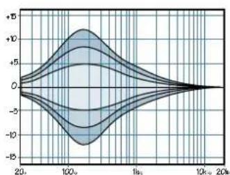
This is a second mid-range EQ control that provides 15 dB of boost or cut centered at the frequency determined by its FREQ knob. It extends down to 100 Hz, which includes the male vocal range and the fundamentals of some lower instruments (guitar, lower brass).
9. LOW MID FREQ

area
| x | y | |-------|--------| | 20k | 0 | | 100k | +15 | | 1k | 0 | | 20k | -15 |Low Mid EQ Freq Sweep
This knob ranges from 100 Hz to 2 kHz and determines the center frequency for the LOW MID EQ filter. This allows you to zero in on the precise narrow band of frequencies you want to have affected by the LOW MID EQ.
10. LOW EQ

area
| x | y | | ------ | ------ | | 20k | -15 | | 100k | -10 | | 1k | -5 | | 10k | 0 | | 20k | 15 |Low EQ
This control gives you up to 15 dB of boost or cut at 80 Hz. The circuit is flat (no boost or cut) at the center detent position. This frequency represents the punch in bass drums, bass guitar, fat synth patches, and some really serious male singers.
Note: Used in conjunction with the Low Cut switch, you can boost the LOW EQ without injecting tons of infrasonic debris into the mix.
11. EQ IN/OUT Switch
This is a true hardware bypass of the Perkins EQ circuitry to insure that there is no coloration of the signal if the EQ is not needed. When this button is out, the EQ controls have no effect on the signal. You can use this switch to make an A/B comparison between the EQ'd signal and the signal without EQ.

We have completely redesigned the EQ circuits in the Onyx Series of mixers, based on the designs of Cal Perkins, an industry-leader in audio engineering for over three decades and long-time Mackie collaborator.
This “neo-classic” design provides the sweet musicality of the British EQ sound, while still maintaining 15 dB of boost and cut with optimum Q and minimum phase shift (in other words, it gives you plenty of control and is pleasing to the car!).
The 4-band equalization has LOW shelving at 80 Hz, LOW MID peaking, sweepable from 100 Hz to 2 kHz on the mono channels, HIGH MID peaking, sweepable from 400 Hz to 8 kHz on the mono channels, and HIGH shelving at 12 kHz. "Shelving" means that the circuitry boosts or cuts all frequencies past the specified frequency. For example, rotating the LOW EQ knob 15 dB to the right boosts bass frequencies below 80 Hz and continuing on
down to the lowest note you ever heard. "Peaking" means that the frequencies around the center frequency are less affected by the EQ the further away they are.
12. AUX Sends
These tap a portion of each channel's signal (pre or post-fader) out to either an effects processor (post-fader) or for stage monitoring (pre-fader). The AUX Send levels are controlled by the channel's AUX 1-6 knobs, and by the AUX SEND MASTERS knobs [55].
These are more than just effects and monitor sends. They can be used to create stereo in-ear monitor mixes, generate separate mixes for recording, for another zone, or "mix-minuses" for broadcast.
13. PAN
PAN adjusts the amount of channel signal sent to the left versus the right outputs.
With the PAN knob hard left, the signal feeds the MAIN LEFT (and GROUP 1 and 3, depending on the setting of the GROUP ASSIGN switches). With the knob hard right, the signal feeds the MAIN RIGHT (and GROUP 2 and 4).
Constant Loudness

The Onyx 4•Bus PAN control employs a design called "Constant Loudness." If you have a channel panned hard left (or right) and then pan to the center, the signal is attenuated 3 dB to maintain the same apparent
loudness. Otherwise, it would make the sound appear much louder when panned center.
14. MUTE
Press this switch to mute the individual channel. This disconnects the channel's signal from all the Groups, the Main Mix, and Aux Send buses (pre* and post-fader). You can still solo the channel (PFL) when the MUTE switch is pushed in.
* If the pre-fader Aux Send's internal jumper is wired for pre-Mute [56], the MUTE switch will not affect the PRE Aux Send.
15. Channel Fader
The fader controls the channel's level...from off to unity gain at the "U" marking, on up to 10 dB of additional gain.
"U" Like Unity Gain

Mackie mixers have a "U" symbol on many of the level controls. This "U" stands for "unity gain,"
meaning no change in signal level. Once you have adjusted the input signal to line-level, you can set the controls at "U" and your signals will travel through the mixer at optimal levels. What's more, many of the labels on our level controls are measured in decibels (dB), so you'll know what you're doing level-wise if you choose to change a control's settings.
16. Signal Level LEDs
These LEDs indicate the channel's signal level after the GAIN and EQ controls, but just prior to the channel's fader. So even if the fader is turned down, you can see if a signal is present.
If you've followed the "Set the Levels" procedure, the -20 and 0 LEDs should light frequently, the +10 LED should light occasionally, and the OL (Overload) LED should not light at all. If the OL LED is blinking frequently, the signal is probably distorted from overdriving the input. Either turn down the GAIN control or turn down the signal at its source.

flowchart
graph TD
    A["INPUT"] --> B["GAIN"]
    B --> C["INSERTLOW"]
    C --> D["EQ"]
    D --> E["POST-EQ"]
    E --> F["PRE-EQ"]
    F --> G["INTERNAL JUMPER"]
    G --> H["POST-EQ"]
    H --> I["EQ IN/OUT"]
    I --> J["MUTE"]
    J --> K["FADER"]
    K --> L["PAN"]
    L --> M["ASSIGN"]
    M --> N["POST-MUTE"]
    N --> O["'POST' SIGNAL"]
    O --> P["'PRE' SIGNAL"]
    P --> Q["TO AUX SENDS 2-6"]
    Q --> R["AUX SEND 1 KNOR"]
    R --> S["TO AUX SEND 1 BUS (POST-FADER)"]
    R --> T["TO AUX SEND 1 BUS (PRE-FADER)"]
    U["DIRECT OUT"] --> V["PRE-EQ"]
    V --> W["POST-EQ"]
    W --> X["INTERNAL JUMPER"]
    X --> Y["POST-EQ"]
    Y --> Z["PRE-EQ"]
    Z --> AA["MUTE"]
    AA --> AB["FADER"]
    AB --> AC["PAN"]
    AC --> AD["ASSIGN"]

17. GROUP and MAIN MIX ASSIGN Switche
Alongside each channel fader are three buttons referred to as channel assignment switches. Used in conjunction with the channel's PAN knob, they are used to determine the destination of the channel's signal.
With the PAN knob [13] at the center detent, the left and right sides receive equal signal levels (GROUPS 1-2, 3-4, and MAIN MIX L-R). To feed only one side or the other, turn the PAN knob accordingly.
If you're doing a mixdown to a 2-track, for example, simply engage the MAIN MIX switch on each channel that you want to hear, and they'll be sent to the MAIN MIX bus. If you want to create a subgroup of certain channels, engage either the 1-2 or 3-4 switches instead of the MAIN MIX, and they'll be sent to the appropriate Group faders. From there, the groups can be sent back to the MAIN MIX (using the MAIN MIX assign switches [70] next to the Group faders), allowing you to use the Group faders as a master control for those channels.
If you're creating new tracks or bouncing existing ones, you'll also use the GROUP ASSIGN switches, but not the MAIN MIX switch. Here, you don't want the subgroups sent back into the MAIN MIX bus, but sent out, via the GROUP OUTS jacks [85], to your multitrack inputs. However, if you're printing tracks via the DIRECT OUTS [76], the channel assignment switches don't matter because the DIRECT OUTS come before the ASSIGN switches.
18. PFL SOLO Switch
This handy switch allows you to hear signals through your headphones or monitor outputs without having to route them to the MAIN or GROUP mixes. Folks use solo in live work to preview channels before they are let into the mix, or just to check out what a particular channel is up to anytime during a session. You can solo as many channels at a time as you like. It won't affect what is coming out the MAIN OUT or GROUP OUT jacks.
The Onyx 4•Bus has two solo modes. PFL (Pre-Fader Listen) is the default solo mode, and the mode used for inputs, including soloing individual channels and the Stereo Returns. AFL (After-Fader Listen) is activated whenever an AFL switch is pressed on an output, including an Aux Send, Matrix, or Group.
PFL solo mode always overrides any AFL solo mode. The Rude Solo LEDS [43] below the SOLO meters indicate which solo mode is active.
Soloed channels are sent to the PHONES output and MONITOR outputs, and also to the MAIN MIX meters. PFL mode (Pre-Fader Listen) sends the channel's signal after the GAIN and EQ controls, but before the channel fader, to the PFL solo bus (and appears on the LEFT meter). AFL mode (After-Fader Listen), sends the signal post-fader (and appears on the LEFT and RIGHT meters), making it ideal for mixdown soloing.

VERY IMPORTANT: Remember, PFL mode taps the channel signal before the fader. If you have a channel's fader set way below "U" (unity gain), PFL solo won't know that and will send a
unity gain signal to the MONITOR OUT and PHONES output. That may result in a startling level boost at these outputs when switching to PFL solo mode.
Stereo Channel Strips
The Onyx 4•Bus mixers each have two stereo channels. The stereo channels have a pair of 1/4"TRS line input connectors.
The stereo channels can be used as mono or stereo line-input channel strips, or to return the signal from an external effects processor connected to an Aux Send (if you want to apply EQ or more flexible auxiliary routing to the signal than is available with the Stereo Returns). These versatile channel strips are nearly as full-featured as the mono channel strips.
19. GAIN Control
If you haven't already, please read "Set the Levels" on page 5.
The GAIN control adjusts the input sensitivity of the stereo line inputs. This allows the signal from the outside world to be adjusted to optimal internal operating levels.
There is 20 dB of attenuation with the knob turned all the way down, ramping up to 20 dB of gain fully up, with a “U” (unity gain) mark at 12:00.
20. HIGH EQ
This control gives you up to 15 dB boost or cut above 12 kHz, and it is also flat at the center detent. Use it to add sizzle to cymbals, and an overall sense of transparency or edge to the keyboards, vocals, guitar, and bacon frying. Turn it down a little to reduce sibilance, or to hide tape hiss.
21. HIGH MID EQ
Short for “midrange,” this knob provides 15 dB of boost or cut at 2.5 kHz. Midrange EQ is often thought of as the most dynamic because the frequencies that define any particular sound are almost always found in this


LOW MID 400Hz

LOW 80Hz
EQ OUT IN
AUX

1

2

3

4

5

6

PAN
MUT
22
23
24
29
30
PFL
the balance control on your home stereo (panning left turns down the right channel, and panning right turns down the left channel).
range. The HIGH MID EQ frequencies include the female vocal range as well as the fundamentals and harmonics for many instruments.
22. LOW MID EQ
This is a second midrange EQ control that provides 15 dB of boost or cut centered at 400 Hz. This includes the male vocal range and the fundamentals of some lower instruments (guitar, lower brass).
23. LOW EQ
This control gives you up to 15 dB of boost or cut below 80 Hz. The circuit is flat (no boost or cut) at the center detent position. This frequency represents the punch in bass drums, bass guitar, fat synth patches, and some really serious male singers.
24. EQ IN/OUT Switch
This is a true hardware bypass of the Perkins EQ circuitry to insure that there is no coloration of the signal if the EQ is not needed. When this button is out, the EQ controls have no effect on the signal. You can use this switch to make an A/B comparison between the EQ'd signal and the signal without EQ.
25. AUX Sends
These tap a portion of each channel's signal out to an effects processor or for stage monitoring. The AUX Send levels are controlled by the channel's AUX 1-6 knobs, and by the AUX SEND MASTERS knobs [55].
26. PAN
PAN adjusts the amount of channel signal sent to the left versus the right outputs. On the stereo channels, the PAN knob works like
27. MUTE
Press this switch to mute the channel. This disconnects the channel's signal from all the Groups, the Main Mix, and Aux Send buses (pre* and post-fader). You can still solo the channel in PFL mode when the MUTE switch is pushed in.
* If the pre-fader Aux Send's internal jumper is wired for pre-Mute [56], the MUTE switch will not affect the PRE Aux Send.
28. Stereo Fader
The fader controls the stereo channel's level, from off to unity gain at the "U" marking, on up to 10 dB of additional gain.
29. Signal Level LEDs
These LEDs indicate the sum of the channel's left and right signal levels after the GAIN and EQ controls, but just prior to the channel's fader. So even if the fader is turned down, you can see if a signal is present.
If you've followed the "Set the Levels" procedure, the -20 and 0 LEDs should light frequently, the +10 LED should light occasionally, and the OL (Overload) LED should not light at all. If the OL LED is blinking frequently, the signal is probably distorted from overdriving the input. Either turn down the GAIN control or turn down the signal at its source.
30. GROUP and MAIN MIX ASSIGN Switches
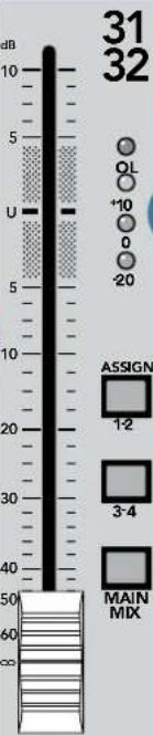
Alongside each channel fader are three buttons referred to as channel assignment switches. Used in conjunction with the channel's PAN knob, they are used to determine the destination of the channel's signal.
The stereo channels are assignable to GROUPS 1-2, 3-4, and the MAIN MIX. With the PAN knob [26] at the center detent, the left and right stereo signal is equally balanced. To feed only one side or the other, turn the PAN knob accordingly.
31. PFL Solo Switch
Like the PFL switch on the mono channels, this switch allows you to hear signals through your headphones or monitor outputs without having to route them to the MAIN or GROUP mixes. Since this is Pre-Fader Listen, you can listen to the stereo signal even when the channel fader is turned down. Unlike the mono channel PFL, the stereo channel PFL is a stereo signal (post-pan control), and therefore retains its left and right stereo image in the headphones and monitors, and appears on both LEFT and RIGHT meters.
The Rude Solo LEDS [43] below the meters indicate which solo mode is active.
Matrix, Compressor, and Metering Section
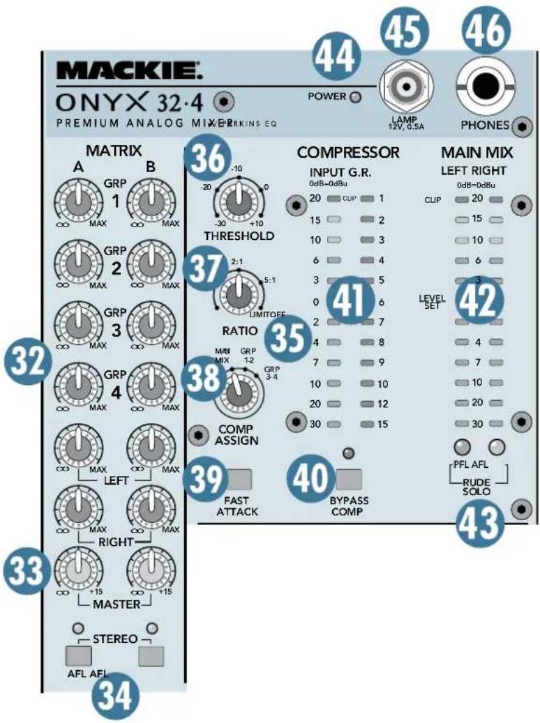
32. MATRIX A and B Input Controls
The Matrix A and B controls allow you to create separate mixes, or a stereo mix, from Groups 1 through 4 and the Left and Right Mix outputs. Simply adjust the six matrix input controls to create the mix you want at the MATRIX A or B outputs.
33. MATRIX A and B MASTER Controls
Use these controls to adjust the overall signal level at the MATRIX A and B outputs.
34. AFL Solo Switch
The AFL switch allows you to hear the Matrix signal through your headphones or monitor outputs. This comes after the MATRIX MASTER, so you can hear the relative signal level of each Matrix output.
When you engage the AFL switch on both MATRIX A and B, the soloed signal appears in stereo in the headphones and monitor outputs. This is useful when you want to use both Matrix outputs to create a stereo mix.
Remember, PFL solo mode always overrides AFL solo mode. If you engage a PFL solo switch on a mono or stereo channel, the AFL solo is disconnected from the headphones and monitor outputs and replaced with the PFL signal. The Rude Solo LEDS below the SOLO meters indicate which solo mode is active.
35. COMPRESSOR/LIMITER
A compressor is used to reduce or limit transient peaks in a signal. As the input level to the compressor increases, the output level from the compressor increases linearly until the threshold point is reached. After that point, the output level no longer increases linearly. Instead, it increases at a reduced rate determined by the ratio setting. In other words, the greater the ratio setting, the less the output level changes as a function of the input level.
A compressor is often used on an individual signal (voice) or group of signals (drums) to smooth out transients and allow signals to sit in the mix without harshly cutting through. A limiter, on the other hand, is often used between the mixer and the amplifier(s) to avoid power amplifier clipping or overdriving the speakers, known as system limiting.
The Onyx 4•Bus design team decided the compressor/limiter functions could be carried out onboard using a new integrated analog stereo compressor/limiter chip designed by THAT Corporation. It provides threshold, ratio, fast/slow attack control and, perhaps most importantly, auto-gain compensation that provides the appropriate amount of makeup gain based on the amount of compression taking place.
The following knobs and switches are used to control the compressor.
36. THRESHOLD
Determines the level at which the compressor begins to act on the incoming signal. It is calibrated in decibels, ranging from -30 to +10 dB.
37. RATIO
Determines the change in output level as a function of the change in input level, once the threshold has been exceeded. The Ratio control ranges from OFF (1:1) to LIMIT ( :1). Thus, if the ratio is 2:1, an increase in input level of 10 dB (assuming the input is above the threshold level) results in a 5 dB increase in output level.
When set to LIMIT, the compressor acts as a peak limiter. After the initial attack time, the output changes very little once the input crosses the threshold.

38. COMP ASSIGN
Use this switch to assign the compressor to either the MAIN MIX, GROUP 1-2, GROUP 3-4, or OFF (not assigned).
When the compressor is assigned to the MAIN MIX, it is inserted in the signal flow after the MAIN MIX fader, so it works as an external dynamics processor. Once the signal crosses the THRESHOLD, boosting the MAIN MIX fader results in little change in the output level (depending on the RATIO setting).
When the compressor is assigned to one of the GROUP pairs, it is inserted in the signal flow before the GROUP faders. In this way, the compressor can act on a group of channels assigned to the subgroup (for example, drum microphones), and the overall level of the compressed group can be mixed into the main mix.
39. FAST ATTACK
The ATTACK setting determines how fast the compressor reacts once the threshold has been exceeded. It also affects the release time, which determines how fast the compressor turns off once the signal falls below the threshold.
With the switch up, the attack and release times are calibrated to respond to the overall signal level without the audible "pumping" and "breathing" artifacts that are sometimes associated with compressors. In most cases, this is the setting you would use for live sound and recording applications.
There may be some situations that require a faster acting attack and release. For example, mic'ing a snare drum produces some fast transient peaks that may get through the compressor before it can act on the signal. Pushing in the FAST ATTACK switch allows the compressor to react much faster on quick transient peaks and release the compression quickly between the peaks. You can experiment with both settings to determine which one works best in your application.
40. BYPASS COMP Switch
When the BYPASS COMP switch is pushed in, the signal bypasses the compressor, but still allows you to see the input signal level to the compressor and the amount of gain reduction applied to the signal on the meters. This is useful when setting up the compressor settings prior to actually engaging the compressor in a live sound application, and for making A/B comparisons between the compressed and uncompressed sound.
41. COMPRESSOR Meters
The INPUT meter indicates the signal level at the input of the compressor. Use this to help determine the setting of the THRESHOLD control. Once the input level crosses the threshold setting, the G.R. (Gain Reduction) meters begin to light (top to bottom), as they indicate how much gain reduction is being applied to the signal.
Note: If the COMP ASSIGN switch [38] is OFF, the COMPRESSOR meters will not indicate any signal.
42. LEFT/RIGHT Level Meters
The Onyx 4•Bus Left and Right Level meters are made up of two columns of twelve LEDs, with three colors to indicate different ranges of signal level, traffic light style. They range from -30 at the bottom, to 0 in the middle, to +20 (CLIP) at the top.
The 0 LED in the middle is labeled 0 dB = 0 dBu.

You may already be an expert at the world of “+4” (+4 dBu=1.23 V) and “-10” (-10 dBV=0.32 V) operating levels. What makes a mixer one or the other is the relative 0 dB VU (or 0 VU) chosen for the meters. A “+4”
mixer, with +4 dBu pouring out the back will actually read 0 VU on its meters. A “-10” mixer, with a -10 dBV
signal trickling out will read, you guessed it, 0 VU on its meters. So when is 0 VU actually 0 dBu? Right now!
Mackie mixers show things as they really are. When 0 dBu (0.775 V) is at the outputs, it shows as 0 dB VU on the meters. What could be easier? By the way, the most wonderful thing about standards is that there are so many to choose from.
Thanks to the Onyx 4•Bus' wide dynamic range, you can get a good mix with peaks flashing anywhere between -20 and +10 dB on the meters. Most amplifiers clip at about +10 dBu, and some recorders aren't so forgiving either. For best real-world results, try to keep your peaks between "0" and "+10."
Remember, audio meters are just tools to help assure you that your levels are “in the ballpark.” You don’t have to stare at them (unless you want to).
Note: The L/R meters indicate solo levels whenever an AFL or PFL solo switch is pushed in.
43. RUDE SOLO Lights
These LEDs flash on and off when a channel's solo is active, as an additional reminder beyond the indicating LEDs next to each PFL or AFL button. The green LED indicates PFL solo mode, and the amber LED indicates AFL solo mode. If you work on a mixer that has a solo function with no indicator lights and you happen to forget you're in solo mode, you can easily be tricked into thinking that something is wrong with your mixer. Hence, the RUDE SOLO lights. It's especially handy at about 3 am when no sound is coming out of your monitors but your multitrack is playing back like mad.
44. POWER Indicator
This LED indicates when power is applied to the Onyx mixer and the POWER switch is on.
45. LAMP Connector
This female BNC connector provides +12 volts DC for gooseneck lamps. See your Mackie dealer for gooseneck lamp recommendations (12 V lamp with BNC connector).
46. PHONES Jack
This is where you plug in your stereo headphones. It is a 1/4" TRS stereo jack and provides the same signal that is routed to the MONITOR outputs [78]. The volume is controlled with the PHONES knob [47].
WARNING: The headphone amp is designed to drive any standard headphones to a very loud level. We're not kidding! It can cause permanent hearing damage. Even intermediate levels may be painfully loud with some headphones. BE CAREFUL! Always start with the PHONES level turned all the way down before connecting headphones to the PHONES jack. Keep it down until you've put on the headphones. Then turn it up slowly. Why? Always remember: "Engineers who fry their ears, find themselves with short careers."
Phones/Monitor, Solo, Mono, and Talkback Section
47. PHONES Level Control
This controls the signal level at the stereo headphone output [46].
48. MONITOR Level Control
This controls the signal level at the MONITOR output [78].
49. SOLO LEVEL Control
The SOLO LEVEL control is used to adjust the volume of the solo'ed signal as it is routed to the MONITOR [78] and PHONES [46] outputs. This control is independent of, and prior to, the MONITOR and PHONES level controls.
This controls the solo signal level for both PFL and AFL solo modes. You can use the SOLO LEVEL control to balance the solo levels with the main or tape levels at the MONITOR or PHONES out.
50. MONO Level Control
In addition to the Left and Right Main Mix outputs, the Onyx 4•Bus provides an independent monophonic output. The Left and Right Main Mix signals are summed and sent to the MONO OUT [84]. This controls the signal level at the MONO output.
51. MAIN TO MON Switch
This switch routes the stereo L/R Main Mix signal (post-fader) to both the Monitor and Phones outputs when there are no solo switches engaged. The L/R Main Mix signal is overridden in the Monitor and Phones outputs by any PFL or AFL solo.
Note: If a PFL solo switch is engaged, it overrides the AFL solo mode, including MAIN TO MON/PHONES.

TALKBACK Section
The talkback feature allows the engineer to communicate with the talent either through the AUX 1-6 [87] Sends, or the MAIN L/R [82] outputs. Connect an external microphone to the TALKBACK MIC XLR [81] connector on the rear panel to use the talkback feature.
52. TALKBACK ASSIGN Switches
These switches route the talkback signal to various outputs, including AUX 1-2, AUX 3-4, AUX 5-6, and MAIN MIX outputs. You might use a pair of Aux Sends to communicate with musicians on-stage through their monitors during a live performance. These could be floor wedges or in-ear monitors.
By the way, it is okay to have more than one TB ASSIGN switch pushed in at the same time. The talkback signal will be routed to all the destinations you have selected. But if you don't have any of the assign switches pushed in, the talkback signal won't go anywhere, and you will wonder why everyone seems to be ignoring you.
53. TALKBACK Level Control
Use this knob to control the level of the talkback signal being routed to the AUX or MAIN L/R outputs.
54. TALKBACK Switch
This is a latching switch, meaning it's always active when the switch is pushed in. As long as the switch is engaged, the talkback signal is routed to the outputs determined by the talkback assign switches [52]. Push the switch again to release it, and the talkback circuit is turned off. An LED above the switch indicates when the TALKBACK switch is active.

Auxiliary Section
This section includes the AUX SEND MASTERS and the STEREO RETURNS. These can be a bit confusing to the uninitiated, so here's the whole idea behind aux sends and returns: sends are outputs and returns are inputs. AUX SENDs tap signals off the channels, via the AUX knobs [12/25], mix these signals together, then send them out the AUX SEND jacks [87].
These outputs are fed to the inputs of an external processor like a reverb or digital delay. From there, the mono or stereo outputs of the external device are fed back to the mixer's STEREO RETURN jacks [80] . These signals are sent through the STEREO RETURN LEVEL controls [64] , and finally delivered to the MAIN MIX bus.
So, the original “dry” signals go from the channels to the MAIN MIX and the affected “wet” signals go from the STEREO RETURNS to the MAIN MIX, and once mixed together, the dry and wet signals combine to create a glorious sound!
The AUX SENDS can also be used to provide another mix for stage monitors. In this case, the STEREO RETURNS aren't used to return the signal. Instead, they can be used as additional stereo inputs.
Aux Send Masters Section
55. AUX SEND MASTERS
The AUX SEND MASTERS provide overall control over the AUX SEND levels, just before they are delivered to the AUX SEND outputs [87]. These knobs go from off ( ) to +15 dB when turned all the way up.
When using the Aux Send for monitors, this is usually the knob you turn up when the lead singer glares at you, points at his stage monitor, and sticks his thumb up in the air. (It would follow that if the singer stuck his thumb down, you'd turn the knob down, but that never happens.)
56. PRE/POST Switch
This switch is used to select whether the Aux send signal is pre-fader or post-fader.
When the PRE/POST switch is up, the Aux send signal is pre-fader, which is usually used for sending to monitors (stage monitor wedges or IEM, in-ear monitor systems). This way, when changes are made to fader levels in the front-of-house mix, it doesn't affect the monitor mix.
When the PRE/POST switch is pushed in, the Aux send signal is post-fader, which is usually used when
you are using the Aux send to go to an effects processor. This way, when fader changes are made, the "wet" signal going to the effects processor moves up and down along with the "dry" signal, maintaining a balance between them.
The pre-fader Aux Sends are post-EQ by default. However, an internal jumper is provided on each channel to change the pre-fader Aux Sends to pre-EQ, if desired. This requires some soldering skills, so contact Tech Support for information on how to access the pre/post-EQ jumpers for the Aux Sends.
57. AFL Solo Switch
The AFL switch allows you to hear the Aux Send signal through your headphones or monitor outputs. This comes after the Aux Send GAIN control, so you can hear the relative signal level on each Aux Send.
Remember, PFL solo mode always overrides AFL solo mode. If you engage a PFL solo switch on a mono or stereo channel, the AFL solo is disconnected from the headphones and monitor outputs and replaced with the PFL signal. The Rude Solo LEDS below the SOLO meters indicate which solo mode is active.
58. MUTE
Press this switch to mute the Aux Send output. When the MUTE switch is pushed in on an Aux Send, you can still solo the Aux Send.
59. CD/TAPE Level Control
This knob controls the level of the signals connected to the left and right TAPE IN jacks. The signal is then sent to the MONITOR/PHONES output (when the TO MON/PHONES switch [60] is pushed in) and the MAIN OUT (when the BREAK switch [61] is pushed in). The CD/TAPE level control provides 10 dB of additional gain when turned fully up.
60. TO MON/PHONES Switch
Press this switch to route the CD/TAPE signal to the Monitor and Phones outputs when there are no solo switches engaged. The Main Mix and CD/TAPE signal is overridden in the Monitor and Phones outputs by any PFL or AFL solo.
61. BREAK (TAPE TO MAIN)
Press this switch to route the CD/TAPE signal to the Main outputs. This actually disconnects the Main Mix signal from the Main outputs and replaces it with the CD/TAPE signal. This allows you to easily start up recorded music during a break without having to mute or turn down the faders on all the channels.
The patch point for the BREAK switch is prior to the MAIN INSERTS, the COMPRESSOR (if selected), and the MAIN MIX fader.
62. STEREO RETURNS AUX Sends
These tap a portion of the STEREO RETURNS signal out to AUX 1-4. This allows you to send a processed signal out to another processor if you want, or to add a processed signal to a monitor mix, or to use the Stereo Return as a stereo input and still be able to send the signal to an external processor or stage monitor.

FEEDBACK LOOP WARNING: It is common to use an Aux Send to route signals to an external processor, and then return the signal from the processor via the Stereo Returns. Since the Stereo Returns on the Onyx 4•Bus have Aux Sends of their own, you could accidentally route the Stereo Return signal to an Aux Send that is being returned via that same Stereo Return. This will cause a feedback loop,
characterized by a LOUD howl or screech through the sound system, followed by howls of discontent from the audience. Be careful with the Aux Sends on the Stereo Returns!
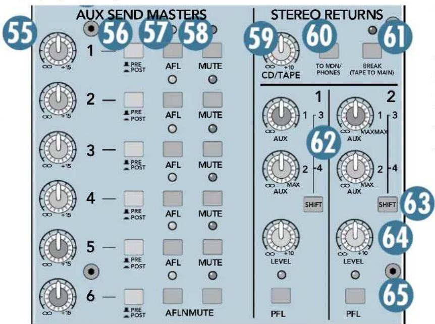
63. SHIFT Switch
The Stereo Returns have two Aux Send controls. When the SHIFT switch is up, they route the signal to Aux 1 and Aux 2, and when the switch is down, they route the signal to Aux 3 and Aux 4.
64. STEREO RETURNS LEVEL Control
This controls the level of the Stereo Return signal being sent to the Main Mix bus. It ranges from off to +10 dB of additional gain when turn fully clockwise.
65. PFL Solo Switch
Like the PFL switch on the stereo channels, this switch allows you to hear signals through your headphones or monitor outputs without having to route them to the Main Mix. Since this is Pre-Fader Listen, you can listen to the Stereo Return signal even when the Stereo Returns Level control is turned down. The Stereo Returns PFL is a stereo signal, and therefore retains its left and right stereo image in the headphones and monitors, and appears on both LEFT and RIGHT meters.
Group Section
There are four group masters (or sub-masters, if you prefer) that feed the four group outs [85].
66. PAN
Note: The Group PAN control works only when the MAIN MIX switch is engaged [70].
PAN adjusts the amount of signal sent to the left versus the right outputs.
With the PAN knob hard left, the signal feeds the MAIN LEFT output, and with the knob hard right, the signal feeds the MAIN RIGHT output.
67. MUTE Switch
Press this switch to mute the Group output. When the MUTE switch is pushed in on a Group, you can still solo the Group signal (see AFL Solo Switch [71] ahead), but it is muted at the Group output [85], the Main output [82] (when the MAIN MIX assign switch is pushed in), and the Matrix output [77].
68. GROUP Fader
This fader controls the Group's signal level, from off to unity gain at the "U" marking, on up to 10 dB of additional gain.
69. Signal Level LEDs
These LEDs indicate the Group's signal level after the Fader, but before the MUTE switch. So if the Group Fader is down, the Signal Level LEDs won't light.
70. MAIN MIX Assign Switch
Push in this switch to send the Group signal to the left and right MAIN OUTS. When the PAN control is centered, the signal is sent equally to the left and right outputs.
The signal sent to the MAIN OUTS is after the Group Insert, Fader, and MUTE switch.

71. AFL Solo Switch
The AFL switch allows you to hear the Group signal through your headphones or monitor outputs. This comes after the Group Fader and before the MUTE switch, so you can hear the relative signal level on each Group even when they are muted.
When you engage the AFL switch on two consecutive odd/even Groups (i.e., 1 and 2, 3 and 4), the soloed signal appears in stereo in the headphones and monitor outputs. This is useful when you are using a pair of Group Sends in stereo to feed an in-car monitoring system.
Remember, PFL solo mode always overrides AFL solo mode. If you engage a PFL solo switch on a mono or stereo channel, the AFL solo is disconnected from the headphones and monitor outputs and replaced with the PFL signal. The Rude Solo LEDS below the SOLO meters indicate which solo mode is active.
72. MAIN MIX Fader
This is the master fader that control the levels at the MAIN OUTS.
When MAIN TO MON [51] is selected in the PHONES/MONITOR Section, the MAIN MIX fader also controls the main mix level in the PHONES and MONITOR outputs [46/78].
When the fader is fully down, the MAIN MIX is off. The "U" marking indicates unity gain, and fully up provides 10 dB of additional gain. Typically, this fader is set near the "U" label and left alone, but it can be used for song fade-outs or quick system-wide mutes.
Rear Panel
This is where all the connections are made to the Onyx 4•Bus (except the headphones and lamps).
73. MIC Input
This is a female XLR connector, which accepts a balanced microphone input from almost any type of microphone. The microphone preamps feature our new Onyx design, with higher fidelity and headroom rivaling any standalone mic preamp on the market today.
The XLR inputs are wired as follows:
Pin 1 = Shield or ground
Pin 2 = Positive (+ or hot)
Pin 3 = Negative (- or cold)
The MIC inputs can accept a balanced line-level input when the PAD [1] switch on the channel strip is pushed in (the input impedance is lower than the LINE input).
74. LINE Input
This is a 1/4" TRS connector, which accepts a balanced or unbalanced line-level input signal from almost any source.
When connecting a balanced signal to the LINE inputs, wire them as follows:
Tip = Positive (+ or hot)
Ring = Negative (- or cold)
Sleeve = Shield or ground
When connecting an unbalanced signal, wire them as follows:
Tip = Positive (+ or hot)
Sleeve = Shield or ground
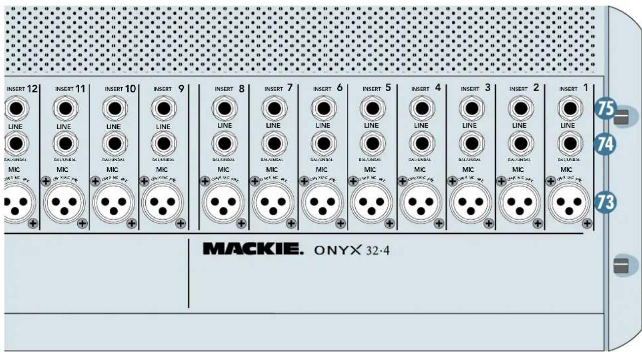
75. INSERT
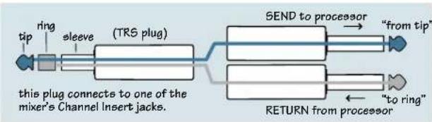
These 1/4" TRS jacks provide a send and return point for each channel. Use the INSERT jacks to connect serial effects devices such as compressors, equalizers, de-essers, or filters to each individual channel.
The INSERT points are after the GAIN and Low Cut controls, but before the EQ and Fader controls. The send (tip) is low-impedance, capable of driving any device. The return (ring) is high-impedance and can be driven by almost any device.
Special insert cables are available, specially designed for this kind of insert jack. They are wired as follows:
flowchart
graph LR
    A["tip"] --> B["ring"]
    B --> C["sleeve"]
    C --> D["(TRS plug)"]
    D --> E["SEND to processor"]
    E --> F["from tip"]
    E --> G["to ring"]
    G --> H["RETURN from processor"]
    H --> I["from tap"]
    style A fill:#fff,stroke:#000
    style B fill:#fff,stroke:#000
    style C fill:#fff,stroke:#000
    style D fill:#fff,stroke:#000
    style E fill:#fff,stroke:#000
    style F fill:#fff,stroke:#000
    style G fill:#fff,stroke:#000
    style H fill:#fff,stroke:#000
    style I fill:#fff,stroke:#000
Tip = Send (output to effects device)
Ring = Return (input from effects device)
Sleeve = Common ground (connect shield to all three sleeves)
Besides being used for inserting external devices, these jacks can also be used as channel direct outputs; post-GAIN, post-LOW CUT, and pre-EQ. This is an unbalanced direct out, in contrast to the DIRECT OUTS on the rear panel, which are balanced direct outputs, post-GAIN, post-INSERT, and pre-EQ.
Here are three ways you use the INSERT jacks:
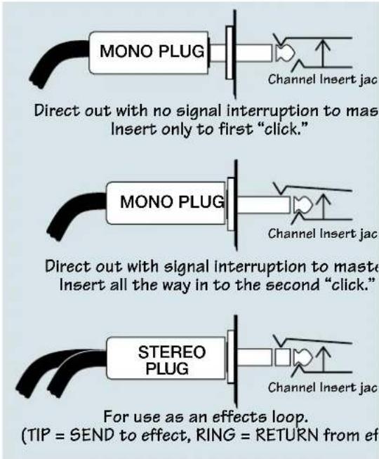
76. DIRECT OUTS
Each of these DB-25 connectors provides balanced direct outputs for eight channels. They are designed to be connected directly to a recorder's analog inputs, and use the TASCAM standard pinout for analog signal connections (the same standard used on the analog cards for the Mackie D8B, DXB, and Hard Disk Recorder).
The signal at the DIRECT OUTS comes after the input GAIN control, Low-Cut switch, and INSERT jack, but before the EQ. This way you can EQ a channel and adjust the channel fader to suit your live mix, but it has no effect on the signal going to the recorder. This provides maximum flexibility for the mixdown stage.

Internal jumpers are provided to change the DIRECT OUTS to post-EQ on a channel-by-channel basis, if desired. This requires some soldering skills, so contact Tech Support for information on how to access the pre/post-EQ jumpers for the DIRECT OUTS.
See Appendix B for a wiring diagram of the DIRECT OUT connectors.
77. MATRIX OUT
These 1/4" TRS jacks provide balanced line-level signals for the MATRIX A and B mixes. These can be connected to the inputs of an amplifier, powered speaker, headphone distribution amplifier, or recording device.
78. MON(ITOR) OUT
These 1/4" TRS jacks provide a balanced line-level signal that can be used to provide another main mix output (with MAIN TO MON [51] selected in the PHONES/MONITOR Section), or to monitor soloed channels.
Connect these outputs to the inputs of an amplifier, powered speaker, headphone distribution amplifier, or recording device.
79. TAPE IN/OUT
Use the TAPE OUT jacks to capture the entire performance to tape. The signal at these jacks is the main mix, after the MAIN INSERTS [83], the MAIN MIX FADER [72], and the COMPRESSOR [41].
Use the TAPE IN jacks to connect the outputs from any stereo line-level signal source, such as a tape player, CD player, MP3 player, television audio, etc., to provide intermission entertainment. Push in the BREAK switch [61] to route the TAPE IN signal to the mains (and disconnect the main mix signal from the MAIN OUT), and push in the TO MON/PHONES switch [60] to route the TAPE IN signal to the MONITOR and PHONES outputs.
80. STEREO RETURNS
These 1/4" TRS jacks accept balanced or unbalanced line-level stereo signals from an external processor or other line-level device. The STEREO RETURNS use a technique called jack normalling. If a signal is plugged into the LEFT (MONO) side and nothing is plugged into the RIGHT side, the signal is automatically routed to both LEFT and RIGHT sides. As soon as something is plugged into the RIGHT side, the normalled connection is broken and the LEFT and RIGHT inputs become stereo inputs (LEFT goes to the LEFT MAIN OUT and RIGHT goes to the RIGHT MAIN OUT).
81. TALKBACK MIC
This is where you plug in your talkback microphone. This female XLR connector does not have phantom power, so use a dynamic microphone or a self-powered condenser microphone.
82. LEFT/RIGHT MAIN OUTS
There are two sets of outputs for the Left/Right Main Outputs: Male XLR connectors that provide balanced line-level signals and 1/4" TRS connectors that provide balanced or unbalanced line-level signals. Each XLR connector is in parallel with its corresponding 1/4" TRS connector, and carries exactly the same signal.
This represents the end of the mixer chain, where your fully mixed stereo signal enters the real world. Connect these to the inputs of your main power amplifiers, powered speakers, or serial effects processor (like a graphic equalizer, or compressor/limiter if you are not using the built-in stereo compressor on the main outs).

83. MAIN INSERTS
These 1/4" TRS jacks are for connecting serial effects such as compressors, equalizers, deessers, or filters. The insert point is after the mix amps and BREAK [61] switch, but before the MAIN MIX faders and the built-in compressor. Refer to the description of the channel insert on the previous page to see how to make this connection.
84. MONO OUT
This male XLR output connector provides a balanced line-level signal that is a combination of the left and right MAIN OUT signals (L+R). You can use this for a separate mix that doesn't require a stereo feed, or to simply test the monaural compatibility of your stereo mix.
85. GROUP OUTS 1-4
These 1/4" TRS output connectors provide balanced or unbalanced line-level signals for connecting to the inputs of any line-level device.
86. GROUP SEND INSERTS
These 1/4" TRS jacks are for connecting serial effects such as compressors, equalizers, deessers, or filters. The insert point is after the mix amps, but before the Group Send Masters (and before the built-in stereo compressor). Refer to the description of the channel insert on the previous page to see how to make this connection.
87. AUX SENDS 1-6
These 1/4" TRS output connectors provide balanced or unbalanced line-level signals for connecting to the inputs of effects devices or stage monitor amplifiers.
88. AUX SEND INSERTS
These 1/4" TRS jacks are for connecting serial effects such as compressors, equalizers, deessers, or filters. The insert point is after the mix amps, but before the Aux Send Masters and the AFL Solo switch (so you can hear the external processor when soloing the aux send). Refer to the description of the channel insert on page 22 to see how to make this connection.
89. Power Receptacle
This is a standard 3-prong IEC power connector. Connect the detachable linecord (included in the box with your Onyx 4•Bus) to the power receptacle, and plug the other end of the linecord into an AC outlet. The Onyx 4•Bus has a universal power supply that can accept any AC voltage ranging from 100 VAC to 240 VAC. No need for voltage select switches. It will work virtually anywhere in the world. That's why we call it a "Planet-Earth" power supply! This also means that it is less susceptible to voltage sags or spikes, providing greater electromagnetic isolation and better protection against AC line noise.
90. POWER Switch
This one is self-explanatory. When the POWER switch is turned ON, power is supplied to the Onyx 4•Bus and the POWER LED on the front panel lights up.
Press the bottom of this switch to put the mixer into standby mode. It will not function, but the circuits are still live. To remove AC power, either turn off the AC mains supply, or unplug the power cord from the mixer and the AC mains supply.

Appendix A: Service Information
If you think your Mackie product has a problem, please check out the following troubleshooting tips and do your best to confirm the problem. Visit the Support section of our website (www.mackie.com/support) where you will find lots of useful information such as FAQs and other documentation. You may find the answer to the problem without having to send your Mackie product away.
Troubleshooting
No Power
- Our favorite question: Is it plugged in?
- Make sure the power cord is securely seated in the IEC socket [89] and plugged all the way into the AC outlet.
- Make sure the AC outlet is live (check with a tester or lamp).
- Is the POWER [90] switch on? Make sure the POWER switch on the rear panel is in the ON position (up).
- Is the POWER LED [44] on the front panel illuminated? If not, make sure the AC outlet is live.
- Are all the lights out in your building? If so, contact your local power company to get power restored.
- If the POWER LED is not illuminated, and you are certain that the AC outlet is live, it will be necessary to have your Onyx 4•Bus serviced. There are no user serviceable parts inside. Refer to “Repair” at the end of this section to find out how to proceed.
Bad Channel
- Is the MUTE button [14/27] pushed in?
- Is the input GAIN control [4/19] for the channel turned up?
• Is the fader [15/28] turned up? - Is the signal source turned up? Make sure the signal level from the selected input source is high enough to light up some of the INPUT meter [16/29] LEDs next to the channel's fader.
-
Is the channel assigned to a bus (GROUP ASSIGN or MAIN MIX button pushed in)?
-
Is there something plugged into the CHANNEL INSERT jack [75]? Try unplugging any INSERT devices.
- Try the same source signal in another channel, set up exactly like the suspect channel.
Bad Output
- Is the associated level control (if any) turned up?
- If it's one of the MAIN OUTPUTS, try unplugging all the others. For example, if it's the 1/4" LEFT MAIN OUT, unplug the XLR LEFT OUTPUT. If the problem goes away, it's not the mixer.
- If it's a stereo pair, try switching them around. For example, if a left output is presumed dead, switch the left and right cords at the mixer end. If the problem stays on the left side, it's not the mixer.
Bad Sound
- Is the input connector plugged completely into the jack?
- Is it loud and distorted? Make sure the input GAIN control for the input is set correctly. Reduce the signal level on the input source if possible.
- If possible, listen to the signal with headphones plugged into the input source device. If it sounds bad there, it's not the Onyx 4●Bus causing the problem.
Noise/Hum
- Turn down the STEREO RETURN LEVEL controls [64]. If the noise disappears, it's coming from whatever is plugged into the STEREO RETURNS [80].
- Turn down each channel, one by one. If the noise disappears, it's coming from whatever is plugged into that channel.
- Check the signal cables between the input sources and the Onyx. Disconnect them one by one. When the noise goes away, you'll know which input source is causing the problem.
- Sometimes it helps to plug all the audio equipment into the same AC circuit so they share a common ground.
Repair
For warranty service, refer to the warranty information on page 35.
Non-warranty service for Mackie products is available at a factory-authorized service center. To locate your nearest service center, visit www.mackie.com, click "Support" and select "Locate a Service Center." Service for Mackie products living outside the United States can be obtained through local dealers or distributors.
If you do not have access to our website, you can call our Tech Support department at 1-800-898-3211, Monday-Friday, during normal business hours, Pacific Time, to explain the problem. Tech Support will tell you where the nearest factory-authorized service center is located in your area.
Need Help?
You can reach a technical support representative
Monday through Friday
during normal business hours, PST at:
1-800-898-3211
After hours, visit www.mackie.com and click Support,
or email us at: techmail@mackie.com
Appendix B: Connections
XLR Connectors
The mono channels use 3-pin female XLR connectors on the MIC inputs. They are wired as follows, according to standards specified by the AES (Audio Engineering Society).
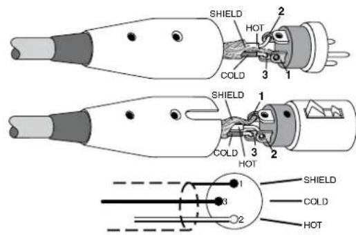
XLR Balanced Wiring:
Pin 1 = Shield
Pin 2 = Hot (+)
Pin 3 = Cold (-)
1/4" TRS Phone Plugs and Jacks
"TRS" stands for Tip-Ring-Sleeve, the three connection points available on a stereo 1/4" or balanced phone jack or plug. TRS jacks and plugs are used for balanced signals and stereo headphones:
Balanced Mono

1/4" TRS Balanced Mono Wiring:
Sleeve = Shield
Tip = Hot (+)
Ring = Cold (-)
Stereo Headphones

1/4" TRS Stereo Unbalanced Wiring:
Sleeve = Shield
Tip = Left
Ring = Right
1/4"TS Phone Plugs and Jacks
"TS" stands for Tip-Sleeve, the two connection points available on a mono 1/4" phone jack or plug. They are used for unbalanced signals.
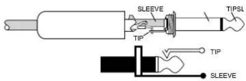
1/4" TS Unbalanced Wiring:
Sleeve = Shield
Tip = Hot (+)
RCA Plugs and Jacks
RCA-type plugs (also known as phono plugs) and jacks are often used in home stereo and video equipment and in many other applications. They are unbalanced and electrically equivalent to a 1/4" TS phone plug.

RCA Unbalanced Wiring:
Sleeve = Shield
Tip = Hot (+)
Unbalancing a Line
In most studio, stage, and sound reinforcement situations, there is a combination of balanced and unbalanced inputs and outputs on the various pieces of equipment. This usually will not be a problem in making connections.
- When connecting a balanced output to an unbalanced input, be sure the signal high (hot) connections are wired to each other, and that the balanced signal low (cold) goes to the ground (earth) connection at the unbalanced input. In most cases, the balanced ground (earth) will also be connected to the ground (earth) at the unbalanced input. If there are ground-loop problems, this connection may be left disconnected at the balanced end.
- When connecting an unbalanced output to a balanced input, be sure that the signal high (hot) connections are wired to each other. The unbalanced ground (earth) connection should be wired to the low (cold) and the ground (earth) connections of the balanced input. If there are ground-loop problems, try disconnecting the unbalanced ground (earth) connection from the balanced input ground (earth) connection, leaving the unbalanced ground connected to the balanced input low (cold) connection only.
In some cases, you may have to make up special adapters to interconnect your equipment. For example, you may need a balanced XLR female connected to an unbalanced 1/4" TS phone plug. Many common adapters can be found at your local electronics supply store.
The balanced-to-unbalanced connection has been anticipated in the wiring of Mackie jacks. A 1/4" TS plug inserted into a 1/4" TRS balanced input, for example, will automatically unbalance the input and make all the right connections. Conversely, a 1/4" TRS plug inserted into a 1/4" unbalanced input will not necessarily tie the ring (low or cold) to ground (earth).
TRS Send/Receive Insert Jacks
Mackie's single-jack inserts are three-conductor 1/4" TRS phone jacks. They are unbalanced, but have both the mixer output (send) and mixer input (return) signals in one connector.
The sleeve is the common ground (earth) for both signals. The send from the mixer to the external unit is carried on the tip, and the return from the unit to the mixer is on the ring.

flowchart
graph LR
    A["tip"] --> B["ring"]
    B --> C["sleeve"]
    C --> D["(TRS plug)"]
    D --> E["send to processor"]
    E --> F["from tip"]
    E --> G["to ring"]
    G --> H["RETURN from processor"]
    I["this plug connects to one of the mixer's Channel Insert jacks."] --> D
Using the Send Only on an Insert Jack
If you insert a 1/4" TS (mono) plug only partially (to the first click) into a Mackie insert jack, the plug will not activate the jack switch and will not open the insert loop in the circuit (thereby allowing the channel signal to continue on its merry way through the mixer).
This allows you to tap out the channel's signal at that point in the circuit without interrupting normal operation.

Note: Do not overload or short-circuit the signal you are tapping from the mixer. That will affect the internal signal.
If you push the 1/4" TS plug in to the second click, you will open the jack switch and create a direct out, which does interrupt the signal in that channel.

Mults and "Y"s
A mult or "Y" connector allows you to route one output to two or more inputs by simply providing parallel wiring connections. You can make "Y"s and mults for the outputs of both unbalanced and balanced circuits.

Remember: Only mult or "Y" an output into several inputs. If you need to combine several outputs into one input, you must use a mixer, not a mult or a "Y."
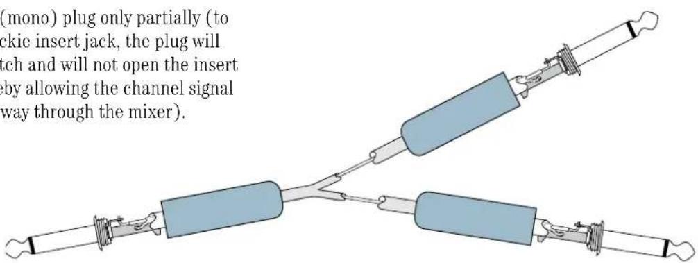
Y-Cord Splitter
DB25 Connectors
The DIRECT OUTS on the back of the Onyx 4•Bus provide balanced direct outputs for all the mono channels on female DB25 connectors. These connectors are pin-for-pin compatible with the analog (not TDIF) DB25 connectors found on TASCAM DTRS recorders, which has become an industry standard for many professional audio manufacturers. They are also the same pinout as the analog cards for the Mackie D8B and hard disk recorders.
| Signal Description | DIRECT OUTS 1-8 | Signal Description | DIRECT OUTS 1-8 | ||
| Pin 1 | + Ch 8 | Pin 14 | - Ch 3 | ||
| Pin 2 | shield Ch 8 | Pin 15 | + Ch 7 | ||
| Pin 3 | - Ch 7 | Pin 16 | shield | Ch 7 | |
| Pin 4 | + Ch 6 | Pin 17 | - Ch 5 | ||
| Pin 5 | shield Ch 6 | Pin 18 | + Ch 5 | ||
| Pin 6 | - Ch 5 | Pin 19 | shield | Ch 5 | |
| Pin 7 | + Ch 4 | Pin 20 | - Ch 4 | ||
| Pin 8 | shield Ch 4 | Pin 21 | + Ch 3 | ||
| Pin 9 | - Ch 3 | Pin 22 | shield | Ch 3 | |
| Pin 10 | + Ch 2 | Pin 23 | - Ch 2 | ||
| Pin 11 | shield Ch 2 | Pin 24 | + Ch 1 | ||
| Pin 12 | - Ch 1 | Pin 25 | shield | Ch 1 | |
| Pin 13 | N/C | ---- |
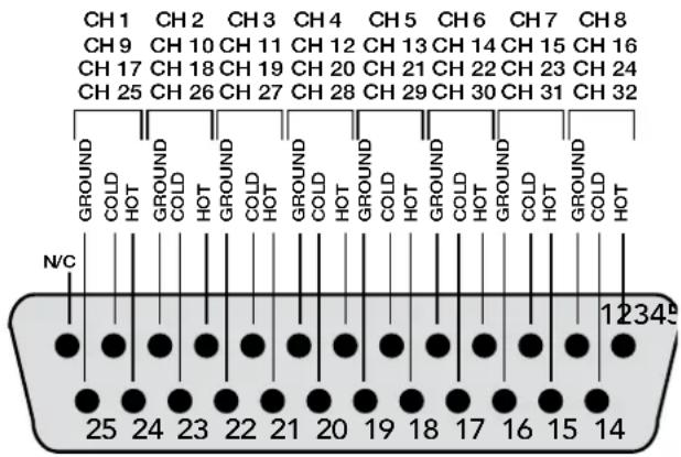
Several companies make DB25-to-DB25 cables specifically for audio, with proper shielding to reduce crosstalk and noise.
DB25 cables that break out to XLR, 1/4" TRS, or TT connectors for connecting to other mixers or audio gear are also readily available. See your Mackie dealer for details.

Correct disposal of this product. This symbol indicates that this product should not be disposed of with your household waste, according to the WEEE Directive (2002/96/EC) and your national law. This product should be handed over to an authorized collection site for recycling waste electrical and electronic equipment (EEE). Improper handling of this type of waste could have a possible negative impact on the environment and human health due to potentially hazardous substances that are generally associated with EEE. At the same time, your cooperation in the correct disposal of this product will contribute to the effective usage of natural resources. For more information about where you can drop off your waste equipment for recycling, please contact your local city office, waste authority, or your household waste disposal service.
Appendix C: Technical Info
Onyx 4•Bus Specifications
Frequency Response
Mic Input to Main Output (Gain @ Unity)
+0, -1 dB, <10 Hz to 80 kHz
+0, -3 dB, <10 Hz to 120 kHz
Distortion (THD & IMD)
Mic Input to Main Output (@ +4 dBu)
THD: < 0.007% 20 Hz to 20 kHz
0.003% @ 1kHz typical
SMPTE IMD: < 0.005% (7 kHz/60 Hz, 4:1)
Dynamic Range
115 dB, Mic In to Main Out
Noise Floor
Signal-to-Noise Ratio:
-87 dBu (ref. +4 dBu, Mic In to Main Out,
32 channels and Main Mix levels at unity)
-89 dBu, (ref. +4 dBu, Mic In to Main Out,
24 channels and Main Mix levels at unity)
Equivalent Input Noise (E.I.N.), 20 Hz to 20 kHz Bandwidth,
150Ω source impedance
-129.5 dBu @ +60 dB gain
Mic Output Noise:
Direct Output: -100 dBu (minimum gain)
Residual Output Noise:
Main Out: -100 dBu (Channel and Main Mix levels off)
Main Out:
32•4: -83 dBu (32 channels and Main Mix levels at unity)
24•4: -85 dBu (24 channels and Main Mix levels at unity)
Common Mode Rejection Ratio (CMRR)
Adjacent Inputs: < -95 dB @ 1 kHz
Input to Output: < -85 dB @ 1 kHz
Input Gain Control Range
High: ±15 dB @ 12 kHz
High Mid: ±15 dB, sweepable from 400 Hz to 8 kHz
Low Mid: ±15 dB, sweepable from 100 Hz to 2 kHz
Low: ±15 dB @ 80 Hz
Stereo Channel (Aux Input) EQ:
High: ±15 dB @ 12 kHz
High Mid: ±15 dB @ 2.5 kHz
Low Mid: ±15 dB @ 400 Hz
Low: ±15 dB @ 80 Hz
Mixer Rated Output
Main Outs: +4 dBu
Aux Send: +4 dBu
Group Send: +4 dBu
Monitor Out: +4 dBu
Matrix Out: +4 dBu
Maximum Rated Output:
+21 dBu @ Main XLR and TRS outputs
Maximum Input Levels
Mic Input: +21 dBu, Gain @ unity, pad out
Mic Input: +30 dBu, Gain @ unity, pad in
Line Input: +21 dBu, Gain @ -20 dB
Tape Input: +30 dBu
Stereo Return: +21 dBu
Maximum Voltage Gain
Mic Input to:
Main Out: 90 dB
Group Out: 80 dB
Aux Sends: 86 dB
Monitor Out: 103 dB
Matrix Out: 105 dB
Phones Out: 103 dB
Line Input to:
Main Out: 70 dB
Group Out: 60 dB
Aux Sends: 66 dB
Monitor Out: 83 dB
Matrix Out: 85 dB
Phones Out: 83 dB
Stereo Return to:
Main Out: 53 dB
Group Out: 43 dB
Aux Sends: 49 dB
Monitor Out: 66 dB
Matrix Out: 68 dB
Phones Out: 66 dB
Input Impedance
Mic Input: 3 kΩ, balanced
Mono Channel Line Input: 34 kΩ balanced
Stereo Returns: 20 k Ω balanced
Talkback Mic: 1 k Ω balanced
Output Impedance
Main Out: 100 Ω balanced, XLR outputs; 300 Ω TRS outputs
Direct Out: 300 Ω
Group Out: 300 Ω
Monitor Out: 300 Ω
Matrix Out: 300 Ω
Aux Sends: 300 Ω
Phones Out: 25 Ω
Channel Level LED (Sensitivity)
0 LED = 0 dBu (normal operating level)
VU Meters
Main Left and Right, Compressor Input, 12 segments: Clip (+20), +15, +10, +6, +3, 0, -2, -4, -7, -10, -20, -30 0 LED = 0 dBu Compressor Gain Reduction, 12 segments: 1, 2, 3, 4, 5, 6, 7, 8, 9, 10, 12, 15 dB
AC Power Requirements
Power Consumption:
Onyx 24•4 100 watts
Onyx 32•4 120 watts
Universal AC Power Supply: 100 VAC - 240 VAC, 50-60 Hz
Onyx 4•Bus Dimensions
Physical Dimensions and Weight
Onyx 24•4
Height: 7.3 in/185 mm
Width: 31.2 in/792 mm
Depth: 21.9 in/555 mm
Weight: 39.5 lb/17.9 kg
Onyx 32•4
Height: 7.3 in/185 mm
Width: 39.8 in/1011 mm
Depth: 21.9 in/555 mm
Weight: 48.0 lb/21.8 kg
LOUD Technologies Inc. is always striving to improve our products by incorporating new and improved materials, components, and manufacturing methods. Therefore, we reserve the right to change these specifications at any time without notice.
"Mackie.", "Onyx," and the "Running Man" are registered trademarks of LOUD Technologies Inc. All other brand names mentioned are trademarks or registered trademarks of their respective holders, and are hereby acknowledged.
©2006-2009 LOUD Technologies Inc. All Rights Reserved.
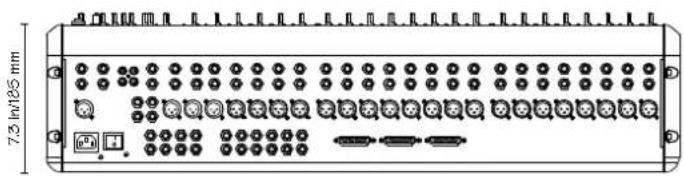
natural_image
Front panel of a multi-pin electronic device with multiple ports and connectors (no text or symbols visible)

natural_image
Front panel of a multi-pin electronic device with ports, connectors, and indicator lights (no text or symbols visible)

Onyx 4•Bus Block Diagram

flowchart
graph TD
    subgraph Inputs
        A["Line"] --> B["Line Input"]
        B --> C["Gain"]
        C --> D["HPF 100Hz"]
        D --> E["4-Band EQ"]
        E --> F["Pin 1"]
        E --> G["Pin 2"]
        E --> H["Pin 3"]
    end

    subgraph Outputs
        I["Main"] --> J["Group"]
        J --> K["Aux 1 (Pre) Aux 2 (Post) Aux 3 (Pre) Aux 4 (Post) Aux 5 (Pre) Aux 6 (Pre) Aux 7 (Post) Aux 8 (Post) Aux 9 (Post) Aux 10 (Post) Aux 11 (Post) Aux 12 (Post) Aux 13 (Post) Aux 14 (Post) Aux 15 (Post) Aux 16 (Post) Aux 17 (Post) Aux 18 (Post) Aux 19 (Post) Aux 20 (Post) Aux 21 (Post) Aux 22 (Post) Aux 23 (Post) Aux 24 (Post) Aux 25 (Post) Aux 26 (Post) Aux 27 (Post) Aux 28 (Post) Aux 29 (Post) Aux 30 (Post) Aux 31 (Post) Aux 32 (Post) Aux 33 (Post) Aux 34 (Post) Aux 35 (Post) Aux 36 (Post) Aux 37 (Post) Aux 38 (Post) Aux 39 (Post) Aux 40 (Post) Aux 41 (Post) Aux 42 (Post) Aux 43 (Post) Aux 44 (Post) Aux 45 (Post) Aux 46 (Post) Aux 47 (Post) Aux 48 (Post) Aux 49 (Post) Aux 50 (Post) Aux 51 (Post) Aux 52 (Post) Aux 53 (Post) Aux 54 (Post) Aux 55 (Post) Aux 56 (Post) Aux 57 (Post) Aux 58 (Post) Aux 59 (Post) Aux 60 (Post) Aux 61 (Post) Aux 62 (Post) Aux 63 (Post) Aux 64 (Post) Aux 65 (Post) Aux 66 (Post) Aux 67 (Post) Aux 68 (Post) Aux 69 (Post) Aux 70 (Post) Aux 71 (Post) Aux 72 (Post) Aux 73 (Post) Aux 74 (Post) Aux 75 (Post) Aux 76 (Post) Aux 77 (Post) Aux 78 (Post) Aux 79 (Post) Aux 80 (Post) Aux 81 (Post) Aux 82 (Post) Aux 83 (Post) Aux 84 (Post) Aux 85 (Post) Aux 86 (Post) Aux 87 (Post) Aux 88 (Post) Aux 89 (Post) Aux 90 (Post) Aux 91 (Post) Aux 92 (Post) Aux 93 (Post) Aux 94 (Post) Aux 95 (Post) Aux 96 (Post) Aux 97 (Post) Aux 98 (Post) Aux 99 (Post)<br>    end<br><br>    subgraph Outputs<br>        O[Main"] --> P["Group"]
        P --> Q["Aux 1 (Pre) Aux 2 (Post) Aux 3 (Pre) Aux 4 (Post) Aux 5 (Pre) Aux 6 (Pre) Aux 7 (Pre) Aux 8 (Pre) Aux 9 (Pre) Aux 10 (Pre) Aux 11 (Pre) Aux 12 (Pre) Aux 13 (Pre) Aux 14 (Pre) Aux 15 (Pre) Aux 16 (Pre) Aux 17 (Pre) Aux 18 (Pre) Aux 19 (Pre) Aux 20 (Pre) Aux 21 (Pre) Aux 22 (Pre) Aux 23 (Pre) Aux 24 (Pre) Aux 25 (Pre) Aux 26 (Pre) Aux 27 (Pre) Aux 28 (Pre) Aux 29 (Pre) Aux 30 (Pre) Aux 31 (Pre) Aux 32 (Pre) Aux 33 (Pre) Aux 34 (Pre) Aux 35 (Pre) Aux 36 (Pre) Aux 37 (Pre) Aux 38 (Pre) Aux 39 (Pre) Aux 40 (Pre) Aux 41 (Pre) Aux 42 (Pre) Aux 43 (Pre) Aux 44 (Pre) Aux 45 (Pre) Aux 46 (Pre) Aux 47 (Pre) Aux 48 (Pre) Aux 49 (Pre) Aux 50 (Pre)<br>    end<br><br>    subgraph Outputs<br>        N[Main"] --> O
        O --> P
        P --> Q
        Q --> R["Aux 1 (Pre) aux.2 to aux.3 to aux.4 to aux.5 to aux.6 to aux.7 to aux.8 to aux.9 to aux.10 to aux.11 to aux.12 to aux.13 to aux.14 to aux.15 to aux.16 to aux.17 to aux.18 to aux.19 to aux.20 to aux.21 to aux.22 to aux.23 to aux.24 to aux.25 to aux.26 to aux.27 to aux.28 to aux.29 to aux.30 to aux.31 to aux.32 to aux.33 to aux.34 to aux.35 to aux.36 to aux.37 to aux.38 to aux.39 to aux.40 to aux.41 to aux.42 to aux.43 to aux.44 to aux.45 to aux.46 to aux.47 to aux.48 to aux.49 to aux.50 to aux.51 to aux.52 to aux.53 to aux.54 to aux.55 to aux.56 to aux.57 to aux.58 to aux.59 to aux.60 to aux.61 to aux.62 to aux.63 to aux.64 to aux.65 to aux.66 to aux.67 to aux.68 to aux.69 to aux.70 to aux.<br>    end<br><br>    subgraph Outputs<br>        N<br>        O --> P<br>        P --> Q<br>        Q --> R<br>        R --> S<br>        S --> T<br>        T --> U<br>        U --> V<br>        V --> W<br>        W --> X<br>        X --> Y<br>        Y --> Z<br>        Z --> AA<br>        AA --> AB<br>        AB --> AC<br>        AC --> AD<br>        AD --> AE<br>        AE --> AF<br>        AF --> AG<br>        AG --> AH<br>        AH --> AI<br>        AI --> AJ<br>        AJ --> AK<br>        AK --> AL<br>        AL --> AM<br>        AM --> AN<br>        AN --> AO<br>        AO --> AP<br>        AP --> AQ<br>        AQ --> AR<br>        AR --> AS<br>        AS --> AT<br>        AT --> AU<br>        AU --> AV<br>        AV --> AW<br>        AW --> AX<br>        AX --> AY<br>        AY --> AZ<br>        AZ --> BA<br>        BA --> BB<br>        BB --> BC<br>        BC --> BD<br>        BD --> BE<br>        BE --> BF<br>        BF --> BG<br>        BG --> BH<br>        BH --> BI<br>        BI --> BJ<br>        BJ --> BK<br>        BK --> BL<br>        BL --> BM<br>        BM --> BN<br>        BN --> BO<br>        BO --> BP<br>        BP --> BQ<br>        BQ --> BR<br>        BR --> BS<br>        BS --> BT<br>        BT --> BU<br>        BU --> BV<br>        BV --> BW<br>        BW --> BX<br>        BX --> BY<br>        BY --> BZ<br>        BZ --> CA<br>        CA --> CB<br>        CB --> CC<br>        CC --> CD<br>        CD --> CE<br>        CE --> CF<br>        CF --> CG<br>        CG --> CH<br>        CH --> CI<br>        CI --> CJ<br>        CJ --> CK<br>        CK --> CL<br>    end<br><br>    subgraph Outputs<br>    M[Main"] --> N
    N --> O
    O --> P
    P --> Q
    Q --> R
    R --> S
    S --> T
    T --> U
    U --> V
    V --> W
    W --> X
    X --> Y
    Y --> Z
    Z --> AB
    AB --> AC
    AC --> AD
    AD --> AE
    AE --> AF
    AF --> BG
    BG --> BH
    BH --> BI
    BI --> BJ
    BJ --> BK
    BK --> BL
    BL --> BM
    BM --> BN
    BN --> CA
    CA --> CB
    CB --> CK
    CK --> LA
    LA --> ME
    ME --> CN
    CN --> CO["To Monitor and Break switch"]
    CO --> CP["To Monitor and Break switch"]
    CP --> CR["To Monitor and Break switch"]
    CR --> CS["To Monitor and Break switch"]
    CS --> CT["To Monitor and Break switch"]
    CT --> CU["To Monitor and Break switch"]
    CU --> CV["To Monitor and Break switch"]
    CV --> CW["To Monitor and Break switch"]
    CW --> CX["To Monitor and Break switch"]
    CX --> CY["To Monitor and Break switch"]
    CY --> CZ["To Monitor and Break switch"]
    CZ --> DA["To Monitor and Break switch"]
    DA --> DB["To Monitor and Break switch"]
    DB --> DC["To Monitor and Break switch"]
    DC --> DD["To Monitor and Break switch"]
    DD --> DE["To Monitor and Break switch"]
    DE --> DF["To Monitor and Break switch"]
    DF --> DG["To Monitor and Break switch"]
    DG --> DH["To Monitor and Break switch"]
    DH --> DI["To Monitor and Break switch"]
    DI --> DJ["To Monitor and Break switch"]
    DJ --> DK["To Monitor and Break switch"]
    DK --> DL["To Monitor and Break switch"]
    DL --> DV["To Monitor and Break switch"]
    DV --> DW["To Monitor and Break switch"]
    DW --> DX["To Monitor and Break switch"]
    DX --> DWD["To Monitor and Break switch"]
    DWD --> DWE["To Monitor and Break switch"]
    DWE --> DWF["To Monitor and Break switch"]
    DWF --> DWG["To Monitor and Break switch"]
    DWG --> DWH["To Monitor and Break switch"]
    DWH --> DWI["To Monitor and Break switch"]
    DWI --> DWJ["To Monitor and Break switch"]
    DWJ --> DWK["To Monitor and Break switch"]
    DWK --> DWL["To Monitor and Break switch"]
    DWL --> DWM["To Monitor and Break switch"]
    DWM --> DWN["To Monitor and Break switch"]
    DWN --> DWO["To Monitor and Break switch"]
    DWO --> DWP["To Monitor and Break switch"]
    DWP --> DWQ["To Monitor and Break switch"]
    DWQ --> DWR["To Monitor and Break switch"]
    DWR --> DWS["To Monitor and Break switch"]
    DWS --> DWT["To Monitor and Break switch"]
    DWT --> DWU["To Monitor and Break switch"]
    DWU --> DWV["To Monitor and Break switch"]
    DWV --> DWW["To Monitor and Break switch"]
    DWW --> DWX["To Monitor and Break switch"]
    DWX --> DWY["To Monitor and Break switch"]
    DWY --> DWZ["To Monitor and Break switch"]
    DWZ --> DWW["Dto Main L-R"]
    DWW["Dto Main L-R"]

    style Inputs fill:#f9f,stroke:#333,stroke-width:2px;

    subgraph Outputs:
    direction TB
        direction LR
            direction LR = Mono, R, T, U, V, W, X, Y, Z, AB, AC, AD, AE, AF, AG, AH, AI, AJ, AK, AL, AM, AN, AO, AP, AQ, AR, AS, AT, AU, AV, AW, AX, AY, AZ, BA, BB, BC, BD, DF; direction TB; direction AP; direction AU; direction AV; direction AW; direction AX; direction AU; direction AV; direction AW; direction AF; direction AG; direction AH; direction AF; direction AW; direction AX; direction AU; direction AV; direction AW; direction AU; direction AV; direction AW; direction AF; direction AG; direction AH; direction AV; direction AW; direction AX; direction AU; direction AV; direction AW; direction AF; direction AG; direction AH; direction AF; direction AW; direction AW; direction AX; direction AU; direction AV; direction AW; direction AU; direction AV; direction AW; direction AF; direction AG; direction AH; direction AV; direction AW; direction AX; direction AU; direction AV; direction AW; direction AF; direction AG; direction AH; direction AF; direction AW; direction AW; direction AX; direction AU; direction AV; direction AW; direction AU; direction AW; direction AW; direction AX; direction AU; direction AV; direction AW; direction AF; direction AG; direction AH; direction AF; direction AW; direction AW; direction AX; direction AU; direction AV; direction AW; direction AU; direction AW; direction AW; direction AX; direction AU; direction AV; direction AW; direction AF; direction AG; direction AH; direction AF; direction AW; direction AW; direction AX; direction AU; direction AV; direction AW; direction AU;
            note right of AB: "Starter Return" or "Main Return"
            note left of AB: "Main Return"
            note right of AC: "Main Return"
            note left of AC: "Main Return"
            note right of AC: "Main Return"
            note left of AC: "Main Return"
            note right of AC: "Main Return"
            note right of AC: "Main Return"
            note left of AC: "Main Return"
            note right of AC: "Main Return"
            note right of AC: "Main Return"
            note left of AC: "Main Return"
            note right of AC: "Main Return"
            note right of AC: "Main Return"
            note left of AC: "Main Return"
            note right of AC: "Main Return"
            note left of AC: "Main Return"
            note right of AC: "Main Return"
            note right of AC: "Main Return"
            note left of AC: "Main Return"
            note right of AC: "Main Return"
            note right of AC: "Main Return"
            note left of AB: "Starter Return" or "Main Return"
            note right of AB: "Main Return"
            note left of AB: "Main Return"
            note right of AB: "Main Return"
            note right of AB: "Main Return"
            note left of AB: "Main Return"
            note right of AB: "Main Return"
            note right of AB: "Main Return"
            note left of AB: "Main Return"
            note right of AB: "Main Return"
            note right of AB: "Main Return"
            note left of AB: "Main Return"
            note right of AB: "Main Return"
            note right of AB : "Main Return"
            note left of AB: "Main Return"
            note right of AB: "Main Return"
            note right of AB: "Main Return"
            note left of AB: "Main Return"
            note right of AB: "Main Return"
            note right of AB: "Main Return"
            note left of AB: "Main Return"
            note right of AB: "Main Return"
            note right of AB: "Main Return"
            note left of AB : "Main Return"
            note right of AB : "Main Return"
            note right of AB : "Main Return"
            note left of AB : "Main Return"
            note right of AB : "Main Return"
            note right of AB : "Main Return"
            note left of AB : "Main Return"
            note right of AB : "Main Return"
            note right of AB : "Main Return"
            note left of AB : "Main Return"
            note right of AB : "Main Return"
            note right of AB : "Main Return"
            note left of AB: "Main Return"
            note right of AB: "Main Return"
            note right of AB: "Main Return"
            note left of AB: "Main Return"
            note right of AB: "Main Return"
            note right of AB: "Main Return"
            note left of AB: "Main Return"
            note right of AB: "Main Return"
            note right of AB : "Main Return"
            note left of AB : "Main Return"
            note right of AB : "Main Return"
            note right of AB : "Main Return"
            note left of AB : "Main Return"
            note right of AB : "Main Return"
            note right of AB : "Main Return"
            note left of AB : "Main Return"
            note right of AB : "Main Return"
            note right of AB: "Main Return"
            note left of AB : "Main Return"
            note right of AB : "Main Return"
            note right of AB : "Main Return"
            note left of AB : "Main Return"
            note right of AB : "Main Return"
            note right of AB : "Main Return"
            note left of AB : "Main Return"
            note right of AB : "Main Return"
            note right of AB: "Main Return"
            note left of AB: "Main Return"
            note right of AB: "Main Return"
            note right of AB: "Main Return"
            note left of AB: "Main Return"
            note right of AB: "Main Return"
            note right of AB: "Main Return"
            note left of AB: "Main Return"
            note right of AB: "Main Return"
            note right of AB:Dto Main Line Out:
                Next step is shown in the default position.
                Note table on the output table:
                Next Step is labeled as 'Switches are shown in the default' with 'out' position.
                Note table on the output table:
                Next Step is labeled as 'Switches are shown in the default' with 'out' position.
                Note table on the output table:
                Next Step is labeled as 'Switches are shown in the default' with 'out' position.
                Note table on the output table:
                Next Step is labeled as 'Switches are shown in the default' with 'out' position.
                Note table on the output table:
                NextStep is labeled as 'Switches are shown in the default' with 'out' position.
                Note table on the output table:
                NextStep is labeled as 'Switches are shown in the default' with 'out' position.
                Note table on the output table:
                NextStep is labeled as 'Switches are shown in the default' with 'out' position.
                Note table on the output table:
                NextStep is labeled as 'Switches are shown in the default' without 'out' position.
                Note table on the output table:
                NextStep is labeled as 'Switches are shown in the default' without 'out' position.
                Note table on the output table:
                NextStep is labeled as 'Switches are shown in the default' without 'out' position.
                Note table on the output table:
                NextStep is labeled as 'Switches are shown in the default' without 'out' position.
                Note table on the output table:

NOTE: Switches are shown in the default out position.

MACKIE ONYX &BUS BLOCK DIAGRAM (#010406_DB/DF)
NOTE: Switches are shown in the default out position.

flowchart
graph TD
    A["Main"] --> B["Group 1 (Pre)"]
    A --> C["Aux 1 (Post)"]
    A --> D["Aux 2 (Pre)"]
    A --> E["Aux 3 (Post)"]
    A --> F["Aux 4 (Pre)"]
    A --> G["Aux 5 (Pre)"]
    A --> H["Aux 6 (Pre)"]
    A --> I["Aux 7 (Post)"]
    A --> J["Matrix A"]
    A --> K["Matrix B"]
    A --> L["AFL L"]
    A --> M["AFL R"]
    A --> N["PFL L"]
    A --> O["PFL R"]

    P["Comp Assign"] --> Q["From Group 3/4"]
    Q --> R["From Group 3/2"]
    R --> S["From Main Mix"]
    S --> T["Form Main Mix"]
    T --> U["Oil"]

    V["Compressor"] --> W["Stereo"]
    W --> X["Input"]
    W --> Y["Master"]
    W --> Z["Threshold"]
    W --> AA["Byease"]
    W --> AB["Ratio"]
    W --> AC["Design"]
    W --> AD["Reduction"]

    AE["SIAD Level"] --> AF["Amplifier"]
    AF --> AG["Amplifier Level"]

    AH["PU/L"] --> AI["AFL R"]
    AI --> AJ["AFL L"]

    AK["Switch"] --> AL["Main Motors"]
    AL --> AM["Main Out L R"]

    AN["PU/L"] --> AO["AFL R"]
    AO --> AP["AFL L"]

    AQ["SDD"] --> AR["Amplifier Level"]
    AR --> AS["SDD Logic"]

    AT["Phone"] --> AU["R Out"]
    AU --> AV["L Out"]

    AW["Monitor Level"] --> AX["L Out"]

    AY["Power Supply"] --> AZ["Input"]

    BA["Input"] --> BB["Output"]

    BC["Input"] --> BD["Output"]

    BE["Input"] --> BF["Output"]

    BG["Input"] --> BH["Output"]

    BI["Input"] --> BJ["Output"]

    BK["Input"] --> BL["Output"]

    BM["Input"] --> BN["Output"]

    BO["Input"] --> BP["Output"]

    BQ["Input"] --> BR["Output"]

    BS["Input"] --> BT["Output"]

    BU["Input"] --> BV["Output"]

    BW["Input"] --> BX["Output"]

    BY["Input"] --> BZ["Output"]

    CA["Input"] --> CB["Output"]

    CC["Input"] --> CD["Output"]

    CE["Input"] --> CF["Output"]

    DG["Input"] --> DH["Output"]

    DI["Input"] --> DJ["Output"]

    DK["Input"] --> DL["Output"]

    DV["Input"] --> DW["Output"]

    DX["Input"] --> DXB["Output"]

    DB["Input"] --> DBR["Output"]

    DCY["Input"] --> DY["Duty"]

    DY --> DYB["Duty"]

    DYX["Duty"] --> DYX

    DYX --> DYX

    DYX --> DYX

    DYX --> DYX

    DYX --> DYX

    DYX --> DYX

    DYX --> DYX

    DYX --> DYX

    DYX --> DYX

    DYX --> DYX

    DYX --> DYX

    DYX --> DYX

    DYX --> DYX

    DYX --> DYX
Owners' Manual
Onyx 4•Bus Gain Structure Diagram

flowchart
graph TD
    A["+21 dBu max in"] --> B["OdB to A"]
    B --> C["EQ MUTE"]
    C --> D["B"]
    D --> E["C"]
    E --> F["D"]
    F --> G["E"]
    G --> H["MIX"]
    H --> I["F"]
    I --> J["G"]
    J --> K["OUTPUTS"]

    subgraph MONO CHANNEL
        L["+30 dBu max in"] --> M["OdB to A P"]
        M --> N["TAPE IN"]
        N --> O["+10 dB up"]
        O --> P["EQ MUTE"]
        P --> Q["H"]
        Q --> R["I"]
        R --> S["PAN ASSIGN"]
        S --> T["FADER"]
        T --> U["OUTPUTS"]

    end

    subgraph MAIN MIX and GROUPS
        V["From F or G (MAIN)"] --> W["LEVEL"]
        W --> X["OUTPUTS"]
        X --> Y["MONO"]
        Y --> Z["+21 dBu max out"]
        Z --> AA["EQ MUTE"]
        AA --> AB["EQ MUTE"]
        AB --> AC["STEREO CHANNEL"]
        AC --> AD["L"]
        AD --> AE["TALKBACK"]
        AE --> AF["LEVEL"]
        AF --> AG["T5 ASSIGN"]
        AG --> AH["+13 dB up"]
        AH --> AI["S Stereo RETURNS"]
        AI --> AJ["M"]
        AJ --> AK["+10 dB up"]
        AK --> AL["E (to Main)"]
        AL --> AM["SOLO (PFL/AFL)"]
        AM --> AN["MONITOR/PHONES"]

    subgraph FROM G (Main and Groups)
        AO["From A, C, D, H, I, M"] --> AP["+4 dB"]
        AP --> AQ["AUX MIX"]
        AQ --> AR["AUX MASTER"]
        AR --> AS["OUTPUT"]
        AS --> AT["MATRIX MIX MATRIX Master"]
        AT --> AU["OUTPUT"]
        AU --> AV["+21 dBu max out"]

    end

    subgraph MACKIE ONYX 40 SERIES LEVEL DIAGRAM
        AW["O10505"]
    end
Please keep your sales receipt in a safe place.
This Limited Product Warranty (“Product Warranty”) is provided by LOUD Technologies Inc. (“LOUD”) and is applicable to products purchased in the United States or Canada through a LOUD-authorized reseller or dealer. The Product Warranty will not extend to anyone other than the original purchaser of the product (hereinafter, “Customer,” “you” or “your”).
For products purchased outside the U.S. or Canada, please visit www.mackie.com/warranty to find contact information for your local distributor, and information on any warranty coverage provided by the distributor in your local market.
LOUD warrants to Customer that the product will be free from defects in materials and workmanship under normal use during the Warranty Period. If the product fails to conform to the warranty then LOUD or its authorized service representative will at its option, either repair or replace any such nonconforming product, provided that Customer gives notice of the noncompliance within the Warranty Period to the Company at: www.mackie.com/support or by calling LOUD technical support at 1.800.898.3211 (toll-free in the U.S. and Canada) during normal business hours Pacific Time, excluding weekends or LOUD holidays. Please retain the original dated sales receipt as evidence of the date of purchase. You will need it to obtain any warranty service.
For full terms and conditions, as well as the specific duration of the Warranty for this product, please visit www.mackie.com/warranty.
The Product Warranty, together with your invoice or receipt, and the terms and conditions located at www.mackie.com/warranty constitutes the entire agreement, and supersedes any and all prior agreements between LOUD and Customer related to the subject matter hereof. No amendment, modification or waiver of any of the provisions of this Product Warranty will be valid unless set forth in a written instrument signed by the party to be bound thereby.
MACKIE.
16220 Wood-Red Road NE • Woodinville, WA 98072 • USA
United States and Canada: 800.898.3211
Europe, Asia, Central and South America: 425.487.4333
Middle East and Africa: 31.20.654.4000
Fax: 425.487.4337 • www.mackie.com
E-mail: sales@mackie.com


- Important Safety Instructions
- Table of Contents
- Introduction......4
- Getting Started ....5
- Hookup Diagrams 6
- Onyx 4•Bus Features ....10
- Appendix A: Service Information 25
- Appendix B: Connections ......27
- Appendix C: Technical Info 30
- Onyx 4•Bus Limited Warranty ....35
- Introduction
- Please write your serial number here for future reference (i.e., insurance claims, tech support, return authorization, etc.)
- Purchased at:
- Date of purchase:
- HOW TO USE THIS MANUAL
- A PLUG FOR THE CONNECTOR SECTION
- More resources on our website at www.mackie.com.
- Getting Started
- READ THIS PAGE!!
- Zero the Controls
- Connections
- Set the Levels
- Instant Mixing
- Other Nuggets of Wisdom
- Hookup Diagrams
- Onyx 24·4 Stage Monitor Mix
- Onyx 24·4 Computer Recording
- Onyx 24·4 House of Worship
- Onyx 4•Bus Features
- Mono Channel Strips
- PAD Switch
- Low-Cut Switch
- 48V Phantom Power Switch
- GAIN Control
- HIGH EQ
- HIGH MID EQ
- HIGH MID FREQ
- LOW MID EQ
- LOW MID FREQ
- LOW EQ
- EQ IN/OUT Switch
- AUX Sends
- PAN
- Constant Loudness
- MUTE
- Channel Fader
- "U" Like Unity Gain
- Signal Level LEDs
- GROUP and MAIN MIX ASSIGN Switche
- PFL SOLO Switch
- Stereo Channel Strips
- GAIN Control
- HIGH EQ
- HIGH MID EQ
- LOW MID EQ
- LOW EQ
- EQ IN/OUT Switch
- AUX Sends
- PAN
- MUTE
- Stereo Fader
- Signal Level LEDs
- GROUP and MAIN MIX ASSIGN Switches
- PFL Solo Switch
- Matrix, Compressor, and Metering Section
- MATRIX A and B Input Controls
- MATRIX A and B MASTER Controls
- AFL Solo Switch
- COMPRESSOR/LIMITER
- THRESHOLD
- RATIO
- COMP ASSIGN
- FAST ATTACK
- BYPASS COMP Switch
- COMPRESSOR Meters
- LEFT/RIGHT Level Meters
- RUDE SOLO Lights
- POWER Indicator
- LAMP Connector
- PHONES Jack
- Phones/Monitor, Solo, Mono, and Talkback Section
- PHONES Level Control
- MONITOR Level Control
- SOLO LEVEL Control
- MONO Level Control
- MAIN TO MON Switch
- TALKBACK Section
- TALKBACK ASSIGN Switches
- TALKBACK Level Control
- TALKBACK Switch
- Auxiliary Section
- Aux Send Masters Section
- AUX SEND MASTERS
- PRE/POST Switch
- AFL Solo Switch
- MUTE
- CD/TAPE Level Control
- TO MON/PHONES Switch
- BREAK (TAPE TO MAIN)
- STEREO RETURNS AUX Sends
- SHIFT Switch
- STEREO RETURNS LEVEL Control
- PFL Solo Switch
- Group Section
- PAN
- MUTE Switch
- GROUP Fader
- Signal Level LEDs
- MAIN MIX Assign Switch
- AFL Solo Switch
- MAIN MIX Fader
- Rear Panel
- MIC Input
- LINE Input
- INSERT
- DIRECT OUTS
- MATRIX OUT
- MON(ITOR) OUT
- TAPE IN/OUT
- STEREO RETURNS
- TALKBACK MIC
- LEFT/RIGHT MAIN OUTS
- MAIN INSERTS
- MONO OUT
- GROUP OUTS 1-4
- GROUP SEND INSERTS
- AUX SENDS 1-6
- AUX SEND INSERTS
- Power Receptacle
- POWER Switch
- Appendix A: Service Information
- Troubleshooting
- No Power
- Bad Channel
- Bad Output
- Bad Sound
- Noise/Hum
- Repair
- Appendix B: Connections
- XLR Connectors
- 1/4" TRS Phone Plugs and Jacks
- Balanced Mono
- Stereo Headphones
- 1/4"TS Phone Plugs and Jacks
- RCA Plugs and Jacks
- Unbalancing a Line
- TRS Send/Receive Insert Jacks
- Using the Send Only on an Insert Jack
- Mults and "Y"s
- DB25 Connectors
- Appendix C: Technical Info
- Onyx 4•Bus Specifications
- Frequency Response
- Distortion (THD & IMD)
- Dynamic Range
- Noise Floor
- Common Mode Rejection Ratio (CMRR)
- Input Gain Control Range
- Mixer Rated Output
- Maximum Input Levels
- Maximum Voltage Gain
- Input Impedance
- Output Impedance
- Channel Level LED (Sensitivity)
- VU Meters
- AC Power Requirements
- Onyx 4•Bus Dimensions
- Physical Dimensions and Weight
- Onyx 4•Bus Gain Structure Diagram
- Please keep your sales receipt in a safe place.
- MACKIE.
Brand : MACKIE
Model : 2404VLZ4
Category : Mixer