
N510 IP PR - Telephone GIGASET - Free user manual and instructions
Find the device manual for free N510 IP PR GIGASET in PDF.


| Product Type | VoIP DECT Phone |
| Brand | Gigaset |
| Model | N510 IP PR |
| Base Station Dimensions | Approx. 120 x 90 x 80 mm |
| Handset Dimensions | Approx. 160 x 50 x 25 mm |
| Base Station Weight | Approx. 200 g |
| Handset Weight | Approx. 130 g |
| Power Supply | Power over Ethernet (PoE) or AC adapter |
| Display | 1.8-inch color display |
| Keypad | Illuminated keypad |
| Audio Features | HD audio, speakerphone |
| VoIP Protocols | SIP, G.711, G.729, G.722 |
| Phonebook | Up to 200 entries |
| Call Logs | Missed, received, dialed calls |
| Intercom | Yes |
| Conference | Up to 3 parties |
| Number of Handsets Supported | Up to 6 |
| Mounting | Wall mountable base |
| Maintenance | Clean with a soft, dry cloth |
| Safety | Keep away from water, do not disassemble |
| Spare Parts | Replacement handsets, batteries, chargers |
| User Manual | 145 pages |
Frequently Asked Questions - N510 IP PR GIGASET
User questions about N510 IP PR GIGASET
0 question about this device. Answer the ones you know or ask your own.
Ask a new question about this device
Download the instructions for your Telephone in PDF format for free! Find your manual N510 IP PR - GIGASET and take your electronic device back in hand. On this page are published all the documents necessary for the use of your device. N510 IP PR by GIGASET.
USER MANUAL N510 IP PR GIGASET
... with impressive internal qualities. With a Gigaset handset, you will be amazed by the perfect sound quality. Your Gigaset can do a lot more than just make calls:
Connect your Gigaset to the Internet and your PC via Ethernet.
Telephone over the Internet. Manage your Gigaset from your PC using a Web browser. Save your Gigaset configuration on your PC after you have set it up. Use your public and private directories on the Internet ( → page 47). Keep the local directories of your connected Gigaset handset and your PC address book synchronised.
Upgrade your Gigaset to a cordless PABX
Configure up to six VoIP connections on your Gigaset. Register up to six handsets and assign each handset its own phone number.
It's easy to configure your Gigaset thanks to the wizards
These help you to configure the VoIP connections for your phone and to assign the receive and send connections to the registered handsets.
Go online with your Gigaset
Use your phone's Info Center and have information specifically provided for the phone from the Internet shown on the display of the registered handsets ( → page 59).
Other practical information
Use the programmable display buttons ( → page 75) on the registered handsets to quickly access important functions on the base and use your phone to read your e-mail messages (without a PC).
Environment
Gigaset Green Home – be environmentally aware when using your phone. For details of our ECO DECT products, visit www.gigaset.com/service
For more information about your phone, visit www.gigaset.com/pro/gigasetn510ippro.
Have fun using your new phone!
Functions of the button on the base
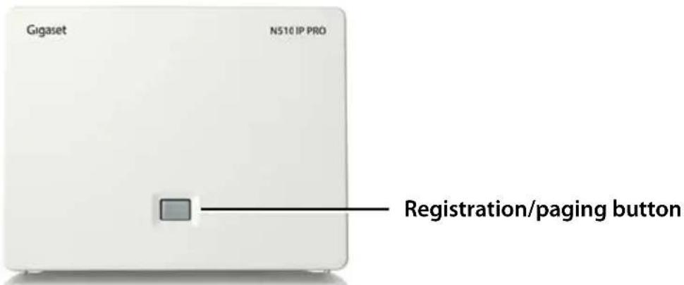
Functions of the registration/paging button on the base
Lights up: LAN connection active (phone is connected to router)
Flashes: Data transfer to LAN connection
Press briefly: Launch paging (handset search),
display IP address of the base on the handset
Press and hold: Set base to registration mode
You can operate, set up and use all the telephone functions on your base with a Gigaset SL610 PRO, C610H, SL78H, SL400H, S79H or S810H handset, for example.
Contents
Gigaset N510 IP PRO ... 2
Functions of the button on the base .... 3
Safety precautions 7
First steps 8
Checking the package contents 8
Setting up the base 9
Connecting the base 10
Registering the handset 15
Setting up the phone – installation wizard 16
Date/time 29
Proceeding 30
Understanding the operating steps in the user manual 31
Menu tree 33
Making calls 35
Making an external call 35
Ending a call 37
Accepting a call 37
Calling Line Identification 38
Notes on phone number display (CLIP) 39
Gigaset HDSP – telephony with brilliant sound quality 40
Making calls using select services 41
Configuring general settings for all calls 41
Activating "anonymous calling" for the next call 44
Configuring settings during an external call 44
Using directories 47
Using online directories 47
Using the private net directory 51
Making cost-effective calls 53
Defining dialling plans 53
Displaying the call duration 53
E-mail notifications 54
Opening the incoming e-mail list 55
Viewing the message header and text of an e-mail 57
Viewing e-mail sender's address 58
Deleting e-mail messages 58
Info Center – continuous Internet access from your phone ..... 59
Logging in for personalised info services 60
Operating the Info Center 61
Displaying information from the Internet as a screensaver 63
Using the network mailbox 64
Activating/deactivating network mailboxes, entering numbers 64
Configuring a network mailbox for fast access 64
ECO DECT 67
Connecting/using handsets 69
Registering handsets 69
De-registering handsets 70
Locating a handset, finding the phone's IP address ("paging") 70
Making internal calls 71
Changing the name of an internal party 73
Changing the internal number of an internal party 74
Configuring the system settings 75
Setting the date/time 75
Quickly accessing functions 75
Protecting the telephone from unauthorised access 77
Setting your own area code 78
Activating/deactivating music on hold 78
Setting the base's IP address in the LAN 78
Configuring VoIP connections 80
Assigning send and receive connections to internal parties 81
Updating the phone firmware 82
Repeater support 83
Restarting the base 83
Resetting the base to the default settings 84
Checking the base MAC address 85
Connecting the phone to a PABX 86
Configuring the phone via the Web configurator 87
Connecting the PC with the telephone's Web configurator 87
Logging into/off the Web configurator 89
Understanding the structure of the Web configurator pages 90
Web configurator menu 95
Functions of the Web configurator 96
Customer Service & Assistance 111
Questions and answers 111
Information on operating Gigaset VoIP telephones with routers with
Network Address Translation (NAT) 113
VoIP status codes 115
Checking service information 118
Environment 119
Our environmental mission statement 119
Environmental management system 119
Disposal 119
Contents
Appendix 120
Caring for your telephone 120
Contact with liquid 120
Authorisation 120
Specifications 121
Glossary 122
Accessories 134
Mounting the base on the wall 138
Index 139
Warning
Read the safety precautions and the user manual before use.
Explain their content and the potential hazards associated with using the telephone to your children.

Use only the power adapter supplied, as indicated on the underside of the base.
Use only the cable supplied for the LAN connection and connect it to the intended port only.

Using your telephone may affect nearby medical equipment. Be aware of the technical conditions in your particular environment, e.g., doctor's surgery. If you use a medical device (e.g., a pacemaker), please contact the device manufacturer. They will be able to advise you regarding the susceptibility of the device to external sources of high frequency energy. Please refer to the Appendix chapter for the specifications of this Gigaset product.

Do not install the base in bathrooms or shower rooms. The base is not splash-proof.

Do not use your phone in environments with a potential explosion hazard (e.g., paint shops).

If you give your phone to a third party, make sure you also give them the user manual.

Remove faulty bases from use or have them repaired by our Service team, as these could interfere with other wireless services.
Please note
◆ Not all of the functions described in this user manual are available in all countries.
◆ The device cannot be used in the event of a power failure. It is also not possible to transmit emergency calls.
Checking the package contents

1

natural_image
Black handheld electronic device with a coiled cable and connector (no visible text or symbols)
natural_image
Coiled cable with two connectors, no text or symbols visible3

natural_image
Illustration of a Gigaset CD and its case (no text or symbols on the covers)4
1 One base, Gigaset N510 IP PRO
2 One power adapter for connecting the base to the mains power supply
3 One Ethernet (LAN) cable (Cat 5 with 2 RJ45 modular jacks) for connecting the base to a router/switch (LAN/Internet)
4 One CD
Please note
The device colour may differ from the one shown here.
Firmware updates
This user manual describes the functions of your phone from firmware version 42.045 onwards.
Whenever there are new or improved functions for your Gigaset, firmware updates are made available for you to download to your base (→ page 82). If this results in operational changes for your phone, a new version of this user manual or the necessary amendments will be published on the Internet at
www.gigaset.com/pro.
Select the product to open the relevant product page for your base, where you will find a link to the user manuals.
To find out what version of firmware is currently loaded → page 118.
Setting up the base
The base station is designed for use in dry rooms in a temperature range of +5°C to +45°C.
▶ Set up the base station at a central point in the building.
Please note
Pay attention to the range of the base. This is up to 300 m in unobstructed outdoor areas and up to 50 m inside buildings. The range is reduced when Eco Mode is activated ( → page 67).
The phone's feet do not usually leave any marks on surfaces. However, due to the multitude of different varnishes and polishes used on today's furnishings, the occurrence of marks on the surfaces cannot be completely ruled out.
Warning
- Never expose the telephone to any of the following: heat sources, direct sunlight or other electrical appliances.
◆Protect your Gigaset from moisture, dust, corrosive liquids and fumes.
First steps
Connecting the base
The following diagram is an overview of all connections for your base. The individual connections are described in detail below. In order to make calls over VoIP, you must connect the base to the Internet (see diagram below) and register at least one handset to the base ( → page 15).

Follow the steps in the order given below:
1 Connect the power cable to the base.
2 Connect the base to the mains power supply.
3 Connect the base to the router/switch to access the Internet and configure the base via the Web configurator.
(Internet connection via router and modem or via router with integrated modem)
4 Connect the PC to the router.
Please note
Your Gigaset N510 IP PRO is supplied with sufficient power via PoE (Power over Ethernet) if the device is connected to an Ethernet switch with PoE functionality (PoE class IEEE802.3af). In this case, it is not necessary to connect the device to the mains power supply and steps 1 and 2 should be omitted.
1. Connecting the power cable to the base

1 Insert the power cable of the power adapter into the connection socket at the rear of the base.
2 Insert the cable into the cable recess provided.
Warning Use only the power cable supplied.
2. Connecting the base to the mains power supply

1 Insert the power adapter into the mains socket.
Warning
If you do not use PoE, the power adapter must be plugged in at all times for operation, as the phone will not work without a mains connection.
3. Connecting the base to a router (Internet)
Data protection notice
When the device is connected to the router, it automatically contacts the Gigaset support server to make it easier for you to configure the devices and to enable communication with the Internet services.
For this purpose, every device sends the following device-specific information once every day:
◆Serial number/item number
◆MAC address
◆Private IP address for the Gigaset in the LAN/its port numbers
◆Device name
◆Software version
On the support server, this information is linked to the existing device-specific information:
◆System-related/device-specific passwords
Your base has a LAN connection for you to connect the base to a router.
Connection to a router is required for Internet telephony VoIP (Voice over Internet Protocol). You can set up and configure up to six accounts (VoIP phone numbers) from one or more VoIP provider(s) on the phone.
You also need a connection to the router for the following features on your phone:
◆ If you want to be notified as soon as new software is available for your phone on the Internet.
◆ If you want the date and time on your phone to be updated by a time server on the Internet.
◆If you want to use info services and/or online directories on your phone.
You can also connect a PC to the router if you want to set your phone via its Web configurator.
For Internet access you need a router connected to the Internet via a modem (this may be integrated in the router).
Please note
For telephony via the Internet, you need a broadband Internet connection.
If you have any queries, visit our website at www.gigaset.com/pro/wiki.

1 Insert a plug from the Ethernet cable supplied (Cat 5 with 2 RJ45 modular jacks) into the LAN connection socket at the side of the base.
2 Insert the second Ethernet cable plug into a LAN socket on the router.
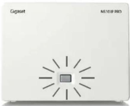
As soon as the cable connecting the phone and router is plugged in and the router is switched on, the button lights up on the front of the base (paging button).
4. Connecting the PC to the router (optional)
You can change the settings on the phone's base using a PC connected to your phone via the router.
PC system requirements:
◆Ethernet port
◆ Web browser such as Microsoft Internet Explorer version 7.0 or higher, or Mozilla Firefox version 3.5 or higher
◆DHCP must be activated (e.g., Windows XP):
Click Start – Settings - Control panel – Network connections.
Double-click the entry for the LAN connection with which your PC is connected to the base.
In the General tab.
▶ Select Internet protocol (TCP/IP) and click the Properties button.
In the General tab, activate the Obtain IP address automatically and Obtain DNS server address automatically options.
▶ Click OK or Close.
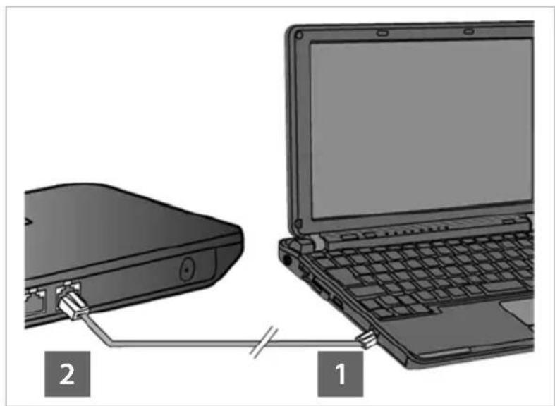
▶ Connect the PC Ethernet
connection 1 to an additional LAN socket 2 on your router.
You will need an Ethernet cable Cat 5 with RJ45 modular jacks.
natural_image
Diagram showing a laptop connected to a device via cable, with labeled parts 1 and 2 (no text or symbols on the diagram itself)Registering the handset
You must register the handset (a) to the base (b).
a) On the handset
▶ Start the registration procedure on the handset in accordance with the handset's user manual.
A message usually appears on the display stating that the handset is searching for a base that is ready for registration.
b) On the base
▶ Within 60 seconds of starting the registration procedure, press and hold the registration/paging button on the base (approx. 3 seconds).
Once the handset has located the base, you will be asked to enter the base system PIN.
▶ Enter the four-digit system PIN for your base on the handset (default is 0000).
Once registration is complete, the handset returns to idle status. The handset's internal number is shown in the display, e.g., INT 1. If not, repeat the procedure.
All base connections are assigned to the handset as receive connections as soon as registration is complete (incoming calls are signalled on the handset and can be answered).
The first configured VoIP connection is assigned as a send connection.
Setting up the phone – installation wizard
Please note
If you have connected your Gigaset N510 IP PRO to a Gigaset PRO PABX (e.g., Gigaset T500 PRO or Gigaset T300 PRO), use the PABX VoIP configuration.
Your Gigaset N510 IP PRO searches the network for a provisioning file and checks whether VoIP accounts already exist. If the phone has existing VoIP accounts, these accounts are configured automatically. You can now make calls with your phone via the Internet.
If the telephone has no existing VoIP accounts, you must configure them manually. This process is described below.
Your phone should be automatically assigned an IP address by the router (i.e., DHCP is enabled on router and phone).
In exceptional cases (e.g., if DHCP is not enabled on the router), you will have to assign a fixed IP address to the base for LAN access. You must enter this IP address on the handset before carrying out the following steps (→ page 78).
In order to be able to make calls with your telephone over the Internet, you must configure at least one VoIP connection on your telephone. You can configure VoIP connections using the following methods:
◆ Using a Web browser on your PC to access the telephone Web configurator, → Quick Start Wizard, page 96.
◆Using your telephone's installation wizard on a connected Gigaset handset. This method is described below using the Gigaset SL610 PRO handset as an example. Configuration is the same for Gigaset C610H, SL78H, SL400H, S79H and S810H.
Auto configuration:
The configuration process for VoIP connections is automated for some VoIP providers. The provider creates a configuration file with all required VoIP access data (the general VoIP provider data and your personal account data). This file is placed on a configuration server on the Internet for downloading to your phone.
Your provider gives you a configuration code.
The installation wizard on your phone ( → page 17) prompts you to enter the code at the relevant point. All the required VoIP data is then downloaded automatically onto your phone.
The configuration file is only transferred via a secure connection (TLS authentication). If the TLS authentication fails, the message key ☑ flashes. Press the message key to display the Certificate error - Please check your certificates in the Web configurator. message. Press the right display key to confirm the message.
Log in to the Web configurator ( → page 89).
The Security ( → page 98) Web page tells you why the secure connection could not be established and what you can do.
If the configuration file fails to download (e.g., because the configuration server is not available), the phone keeps trying to establish a connection until the file is downloaded successfully to the phone.
If VoIP connections have not yet been generated on the phone, you can start the installation wizard directly on the handset. The wizard allows you to make all necessary settings for your phone.
Two individual wizards are combined to form the installation wizard:
1 IP wizard
2 Connection wizard
Launching the installation wizard

If the handset battery has sufficient charge, the message key ☑ on your handset will flash.
▶ Press the message key 📧.
1. IP wizard – making VoIP settings
You will see the following display:

Before you can use VoIP to phone any other numbers over the Internet, the fixed line or the mobile network, you need the services of a VoIP provider which supports the VoIP SIP standard.
Prerequisite: You have registered with a VoIP provider (e.g., via your PC) and set up at least one VoIP account (IP account).
To use VoIP, you now need to enter the access data for your VoIP account. You will receive all the necessary data from your VoIP provider. This will include:
Either:
◆Your username (if requested by the VoIP provider).
This is the username of your IP account (caller ID), and is frequently identical to your phone number.
◆Your authentication name or login ID
◆The (login) password registered with the VoIP provider
◆General settings for your VoIP provider (server addresses etc.)
Or:
◆An auto configuration code (activation code)
Your Gigaset phone's IP wizard can help you make these entries.
Please note
You can configure up to six VoIP connections. When you get started with the phone, you can initially only configure one VoIP connection. You can configure additional VoIP connections later with the IP wizard (→ page 80) or the Web configurator.
Launching the IP wizard
Prerequisite: The phone is connected to the router. The router is connected to the Internet (→ page 12).
▶ Press on the centre of the control key ☐ or on the right display key Yes to launch the IP wizard.
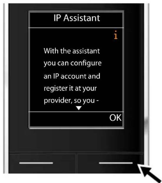
Information about the IP wizard appears in the display.
▶ Press the bottom of the control key ☐ to scroll down.
▶ Press the OK display key to continue.

A list of all possible IP connections is shown in the display (IP 1 to IP 6). VoIP connections that are already configured are marked with ☑.
▶ If necessary, press down on the control key to select a connection.
▶ Press the OK display key to continue.
You will see the following display:

Your VoIP provider has supplied you with an authentication name/password and, where applicable, a user name:
▶ Press the key below No on the display screen.
For further information, please see "Downloading VoIP provider data" → page 22.
You have received an auto configuration code (activation code) from your VoIP provider:
▶ Press the key below Yes on the display screen.
For further information, please see "Entering the auto configuration code" → page 21.
No Internet connection:
The phone requires an Internet connection for you to register your telephone with a VoIP provider. If a connection cannot be made, one of the following messages is displayed:
◆ If the phone cannot establish a connection to the router, the message IP address not available is displayed.
Check the plug connection between the router and the base and check the settings on the router.
Your phone is preconfigured for dynamic assignment of the IP address. In order for your router to "recognise" the phone, dynamic IP address assignment must also be activated on the router, i.e., the router's DHCP server must be activated.
If the DHCP server cannot or should not be activated, you must assign a fixed IP address to the phone (→ page 78).
If the phone cannot establish a connection to the Internet, the message Internet connection not available is displayed.
The IP server may be temporarily unavailable. In this case, try to make a connection again later.
Otherwise, check the plug connection between the router and the modem or DSL connection and check the settings on the router.
▶ Press OK to close the IP wizard.
You will then need to call up the wizard later via the menu to configure the IP connection.
Entering the auto configuration code

▶ Using the keypad, enter the auto configuration code you received from the provider (max. 32 characters).
▶ Press the key below OK on the display screen.
All data required for VoIP telephony is loaded directly from the Internet to your phone.
When all the data has been successfully loaded onto your phone, Your IP account is registered at your provider appears on the display.
For further information, please see „2. Connection wizard“, page 25.
Downloading VoIP provider data
The connection wizard establishes a connection with the Gigaset configuration server on the Internet. Various profiles with general access data for different VoIP providers can be downloaded here.
After a brief period you will see the following display:

A list of countries is loaded.
▶ Press up or down on the control key repeatedly until the country in which you want to use the phone is selected in the display.
▶ Press the key below OK on the display screen to confirm your selection.

A list of the VoIP providers with general access data profiles is available on the configuration server is displayed.
▶ Press up or down on the control key repeatedly until your VoIP provider is selected in the display.
▶ Press the key below OK on the display screen to confirm your selection.
The general access data for your VoIP provider will be downloaded and saved on the phone.
You have not been able to download your provider's data
If your VoIP provider does not appear in the list, i.e. its general data is not provided for download, you must cancel the IP wizard:
▶ Briefly press the end call key 📞 repeatedly until End assistant? appears in the display and then press the display key Yes.
You can perform the subsequent steps of the installation wizard.
You must then make the required VoIP provider and IP account settings using the Web configurator. You receive the general provider data from your VoIP provider.
You can change the assignment of the VoIP connection as send/receive connection at a later time via the telephone menu or the Web configurator.
Entering user data for your VoIP account
You are now prompted to enter your personal access data for your VoIP account.
The following are provider-dependent:
◆ Authentication, Authentication,
Please note ...
... when entering access data, it is case sensitive.
To switch between upper and lower case and digits, press the # → key (several times if necessary). You can see briefly in the display whether upper case, lower case or digit input is selected.
Characters entered incorrectly can be deleted using the left display key below <C. The character to the left of the cursor is deleted.
You can navigate within the input field using the control key (left/right).
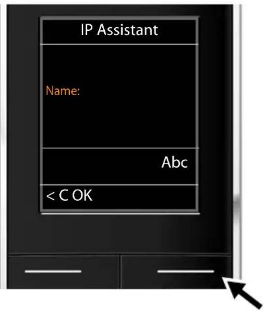
▶ Using the keypad, enter the User ID that you received from your VoIP provider.
▶ Press the key under OK on the display screen.
First steps

▶ Use the keypad to enter your password.
▶ Press the key under OK on the display screen.
▶ Using the keypad, enter the user name that you received from your VoIP provider.
▶ Press the key under OK on the display screen.


Once you have made all the necessary entries, the IP wizard will try to register the phone with the VoIP provider.
After successful registration, the message "Your IP account is registered at your provider" appears in the display.
The connection wizard starts.
2. Connection wizard
Using the connection wizard, you can assign the previously configured connections ( → page 18) to the internal parties as receive or, if applicable, as send connections. Internal parties are the registered handsets.
◆ Receive connections are the phone numbers (connections) on which you can be called. Incoming calls are only forwarded to the internal parties (end devices) for which the relevant connection is assigned as receive connection.
◆ Send connections are the numbers that are sent to the called party. The network provider calculates charges based on the send connections. You can assign each internal party a number or the associated connection as a send connection.
◆ Each connection (number) of your phone can be both a send as well as a receive connection. You can assign each connection to several internal parties as a send and/or receive connection.
Default assignment
All configured connections are assigned to the handsets as receive connections at registration/start-up.
The first configured VoIP connection is assigned to the handsets as a send connection.
Launching the connection wizard
a.
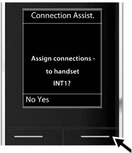
▶ Press the display key Yes if you wish to change the setting for the send and receive connections of the handset with the internal name INT1.
▶ Press the display key No if you do not wish to change the setting for this handset.
b.

The list of receive connections currently assigned is displayed.
Press down on the control key ☐ to scroll through the list if necessary.
▶ Press the display key Change if you wish to change the receive connection setting.
▶ Press the display key OK if you do not wish to change the setting.
Press OK to skip the following steps. Continue from → d. Press Change to display the following:
C.

If no calls to the VoIP connection IP1 are to be signalled on the handset:
▶ Press right on the control key □ to set to No.
The updated list of receive connections is displayed one more time for you to check. Press the display key OK to confirm the assignment.
d.
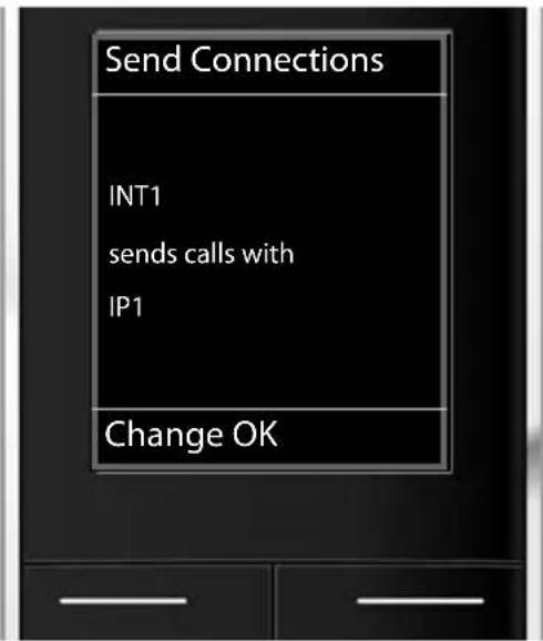
The send connection currently set for the handset is displayed: IP1.
▶ Press the display key OK if you do not wish to change the setting. Skip the following step.
▶ To change the setting, press the display key Change.
e.
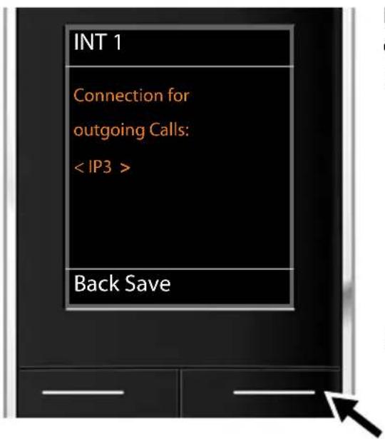
If the handset is to make calls via a different connection/phone number:
▶ Press right on the control key ▶ repeatedly, until the required connection is displayed (in the example, IP3).
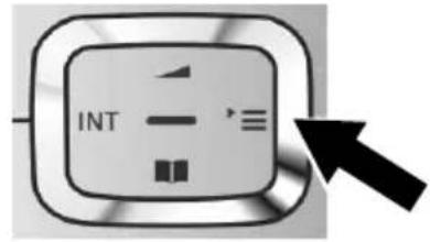
▶ Press the display key Save to save the settings.
Instead of a connection, you can also select Sel. at each call. Each time you make a call, you can then select the connection you wish to use on this handset.
If other handsets are already registered to the base, you are requested to assign send and receive connections for the handsets. The following is shown in the display:
Assign connections to handset?
▶ Perform steps a. to e. for each registered handset.
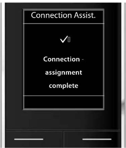
After successfully configuring the settings, you will briefly see this display.
Completing the installation
The handset then returns to idle status (an example of the display in idle status):
Displays
◆Reception between the base and the handset:

Green: Eco Mode enabled
◆Charge status of the batteries:

◆INT 1
Internal name of the handset

Please note
To protect your phone and its system settings from unauthorised access, you can define a 4-digit number code (system PIN) known only to yourself. This code must be entered before you can register/de-register handsets or alter your phone's VoIP or LAN settings.
The default system PIN is 0000 (4 x zero).
For instructions on changing the PIN → page 77.
Date/time
There are two methods of setting the date and time:
By default, your phone is configured so that the date and time are transferred from a time server on the Internet, provided it is connected to the Internet.
You can activate/deactivate the synchronisation with a time server via the Web configurator ( → page 106).
- You can also set the date and time manually via the menu on one of the registered handsets (→ page 75).
The date and time must be set in order to show the correct time for incoming calls, for example.
First steps
Proceeding
Now you have successfully set up your phone, you'll want to adapt it to your personal requirements. Use the following guide to quickly locate the most important subjects.
Information on ... ... is located here.
Making external calls and accepting calls page 35
Storing your own area code in the telephone page 78
Setting Eco Mode page 67
Operating the telephone on a PABX page 86
Registering Gigaset handsets to the base page 69
Using online directories page 47
Entering additional VoIP accounts page 80
Configuring the phone via the Web configurator page 87
If you have any questions about using your phone, please read the tips on troubleshooting ( → page 111) or contact our Customer Care team ( → page 111).
Understanding the operating steps in the user manual
The operating steps have been shortened and are based on a Gigaset SL610H PRO handset.
Example:
The display:

means:

▶ Press right on the control key □ to open the main menu.
▶ Press right, left, down and up on the control key 🔊 to navigate to the Settings submenu.
▶ Press the display key OK to confirm your selection.
▶ Press down on the control key □ until the Eco Mode menu option is highlighted.
▶ Press the display key OK to confirm your selection.
First steps
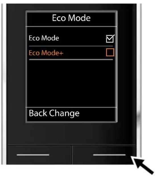
▶ Press down on the control key □ until the Eco Mode+ menu option is highlighted.
▶ Press the display key Change to activate/deactivate the function.
The change is effective immediately and does not need to be confirmed.

▶ Press the key below Back to skip back to the previous menu level. Or
▶ Press and hold the end call key 🔒 to return to idle status.
You can use the base functions of your Gigaset N510 IP PRO via a registered handset. On the Gigaset SL610 PRO, C610H, SL78H, SL400H, S79H or S810H handsets, the base functions are contained in the handset menu. Handset-specific functions are not shown below. In place of the handset-specific functions, "..." appears in the submenus. Function names may vary between the individual handsets.
On some Gigaset handsets, you can choose between Simplified (standard mode) and Complete (expert mode) menu views. Menu options that are only available in expert mode are marked with the E icon.
To open the main menu: press ▶ when the handset is in idle status:

Messaging
E-mail → page 54

Voice Mail

flowchart
graph TD
    A["Play Messages"] --> B["Net AM: IP1"]
    A --> C[":"]
    A --> D["Net AM: IP6"]
    E["Network Mailboxes Net AM: IP1"] --> F[":"]
    E --> G["Net AM: IP6"]
    H["Set Key 1 Net AM: IP1"] --> I[":"]
    H --> J["Net AM: IP6"]
→ page 64
→ page 64
→ page 64

Select Services

flowchart
graph TD
    A["Next Call anon."] --> B["Call Divert Internal Line"]
    B --> C["IP1"]
    B --> D[":"]
    B --> E["IP6"]
    F["Call Waiting"] --> G["All Calls anon."]
    G --> H["Transfer (ECT)"]
→ page 44
→ page 42
→ page 42
→ page 43
→ page 41
→ page 43

Info Centre
only on Gigaset Gigaset SL610 PRO, SL78H, SL400H,
S79H oder S810H handset;
on Gigaset C610H handsets you will find the Info
Center in the Additional Features menu.
→ page 59

Settings

flowchart
graph TD
    A["Date/Time → page 75"] --> B["Audio Settings ..."]
    B --> C["Music on Hold"]
    C --> D["Registration ..."]
    D --> E["De-reg. Handset"]
    E --> F["Telephony ..."]
    F --> G["Area Codes"]
    G --> H["VoIP Assistant"]
    H --> I["Send Connections INT 1 ... INT 6"]
    I --> J["Rec. Connections INT 1 ... INT 6"]
    J --> K["Access Code"]
    K --> L["System"]
    L --> M["..."]
    M --> N["Base Reset"]
    N --> O["Base Restart"]
    O --> P["Repeater Mode"]
    P --> Q["Local Network"]
    Q --> R["Update Firmware"]
    R --> S["System PIN"]
    S --> T["Eco Mode Eco Mode"]
    T --> U["Eco Mode+"]

    style A fill:#f9f,stroke:#333
    style T fill:#f9f,stroke:#333

    note1["→ page 78"]
    note2["→ page 70"]
    note3["→ page 78"]
    note4["→ page 81"]
    note5["→ page 82"]
    note6["→ page 86"]
    note7["→ page 84"]
    note8["→ page 84"]
    note9["→ page 83"]
    note10["→ page 78"]
    note11["→ page 82"]
    note12["→ page 77"]
    note13["→ page 67"]
    note14["→ page 67"]

Contacts
You can make calls on a Gigaset handset connected to your base.
Please note
You can make up to four external calls at the same time via your base, depending on the quality of your DSL connection.
Making an external call
External calls are calls made via the public telephone network (fixed line, mobile phone network) or via the Internet (VoIP).
To make an external call, you need to define one of the phone connections as a send connection. You have the following options:
Assign a connection to the handset as a send connection permanently (→ page 81). If necessary, you can use a "fallback" connection via a display key (→ page 76).
◆Select a send connection on the handset each time you make a call.
Permanently assigned send connection
Prerequisite:
A specific connection is assigned to the handset as a send connection ( → page 81).


Enter the number and press the talk key.
The number is dialled.
Or:

Press and hold. A list of your phone's connections will be displayed.

Select a line.

Press the display key or the middle of the control key.

Enter the number. The number is dialled approximately 3.5 seconds after the last digit is entered.
Instead of the talk key ↗, you can also press the speaker key □ on the handset to make a call in speaker mode.
In this user manual, each of these variants is indicated by "Press the talk key".
The dialled number and the send connection used are shown in the display (e.g., via IP2). The connection name you have assigned is displayed where available. Otherwise, the default name is used.
Please note
If you use VoIP to make a call to the fixed line, you may also have to dial the area code for local calls (depending on the provider). You can avoid having to dial your own area code by entering it in the configuration and activating the Predial area code for local calls via VoIP option (see Web configurator, → page 103).
Selecting a line for each call
Prerequisite: "Sel. at each call" has been assigned to the handset instead of a send connection (→ page 81).


Enter the number and press the talk key. The list of all the phone's connections is displayed.

Select a line.


Press the display key or the middle of the control key.
If a dialling plan has been defined for the dialled phone number ( → page 102), then the send connection specified in the dialling plan is used.
Please note
◆ You can cancel the dialling process with the end call key 🔒.
◆ You are shown the duration of the call while the call is in progress.
◆ Dialling using the directories or the handset's call and redial lists saves you retyping numbers.
If you have multiple handsets registered to the base, you can make internal calls free of charge (page 71).
Using an alternative connection/connection list on the display key
Prerequisite: You have assigned an "alternative connection" or the list with all configured connections to a display key on the handset ( → page 76).
Sel.Conn.
Press the display key.

Select a line.


Press the talk key or display key.

Enter a number. The number is dialled approximately 3.5 seconds after the last digit is entered.
Any dialling plan ( → page 102) that has been defined for the dialled phone number is ignored. The selected send connection is always used.
Calling an IP address (provider-dependent)
You can also dial an IP address instead of a phone number.
▶ Press the star key * △ to separate the sections of the IP address (e.g. 149*246*122*28).
▶ If necessary, press the hash # -# key to attach the SIP port number of the person you are calling to the IP address (e.g. 149*246*122*28#5060).
If your VoIP provider does not support the dialling of IP addresses, each part of the address will be interpreted as a normal phone number.
Displaying the phone number you are calling (COLP)
Prerequisites:
- Your network provider supports COLP (Connected Line Identification Presentation). You may need to activate COLP with the provider (ask your provider about this).
◆ The called party has not activated COLR (Connected Line Identification Restriction).
For outgoing calls, the phone number of the connection on which the call is received is displayed on the handset.
The displayed number may differ from the number you have dialled. Examples:
◆The called party has activated call divert.
◆The call is answered by another connection within a PABX system.
If there is an entry in the directory for this phone number, the corresponding name will be displayed.
Please note
◆The actual number of the connection you have reached (or the assigned name) is displayed instead of the called number during call swapping, conference calls and consultation calls.
- When the phone number is copied to the directory and the redial list, the dialled number (not the displayed number) is copied.
Ending a call

Press the end call key.
Accepting a call
An incoming call is indicated on a Gigaset handset in three ways: by ringing, by a display on the screen and by the talk speaker key ↗.
Please note
Only calls to the receive connections assigned to the handset are signalled ( → page 82).
The following applies in particular if VoIP connections are configured on your base:
If you have not assigned the receive connections on your phone, all incoming calls are signalled on all registered handsets.
If you have assigned connections but not assigned a connection to any handset as the receive connection, calls on this connection will not be signalled.
If a call cannot be assigned to any connection on the phone, this call is signalled on all handsets.
You can accept the call on the handset by:
▶ Pressing the talk key ↗.
▶ Pressing the speaker key ☐.
To deactivate the ringtone, press the Silence display key. You can accept the call as long as it is displayed on the screen.
If you press the end call key ☐, the call is rejected.
Calling Line Identification
When you receive a call, the caller's number and/or name is displayed on the screen if the following prerequisites are met:
◆Your network provider supports CLIP, CLI and CNIP.
- CLI (Calling Line Identification): The caller's number is transmitted.
- CLIP (Calling Line Identification Presentation): The caller's number is displayed.
– CNIP (Calling Name Identification Presentation): The caller's name is displayed.
◆You have requested CLIP or CNIP from your network provider.
◆The caller has requested CLI from the network provider.
Call display
If the caller's number is in the handset's directory, the caller's name will be shown.
You can use the display to decide which receive connection the call is directed to.
Example of display:

1 Number or name of caller
2 Receive connection: Indicates which of your phone numbers the caller has dialled. The name you set when configuring the phone or the default name is displayed (IP1 to IP6).
The following is displayed instead of the number:
◆External, if no number is transmitted.
Adopting the name from the online directory
Instead of the phone number appearing in the call display, you can display the name under which the caller is saved in the online directory.
Prerequisites:
◆ The provider of the online directory you have set for your telephone supports this function.
◆ You have activated the "Display of caller's name" function via the Web configurator.
◆ The caller has requested Calling Line Identification and has not suppressed the function.
◆Your telephone is connected to the Internet.
◆The caller's number is not saved in the handset's local directory.
Display with CNIP
If you have CNIP, then the name (location) that is registered with your network provider for the caller's number is displayed. If the number of the caller is stored in your directory, the CNIP display is replaced by the corresponding directory entry.
Example of display:

1 Caller's number
2 Name and location
Notes on phone number display (CLIP)
The number of the caller is shown in the display of your Gigaset phone handset by default. You do not have to change any other settings on your Gigaset telephone.
However, if the caller's number is not displayed, this can be due to the following:
◆You have not requested CLIP from your provider
- Your telephone is connected via a PABX or a router with an integrated PABX (gateway) that does not transmit all information.
Is your telephone connected via a PABX/gateway?
You can establish this by checking for an additional device connected between your telephone and home connection, e.g., a PABX, gateway etc. In most cases, simply resetting this device will remedy the situation:
▶ Briefly disconnect the PABX power plug. Re-insert the plug and wait for the device to restart.
If the caller number is still not displayed:
▶ Check the CLIP (phone number display) settings of your PABX and activate this function if necessary. In the user manual for the device, search for the term "CLIP" (or an alternative term such as "calling line identification", "phone number transmission", "caller ID" etc.). If necessary, contact the device manufacturer.
If this does not resolve the problem, it is possible that your network provider does not provide the CLIP service for this number.
Have you requested the phone number display service from your network provider?
▶ Check whether your provider supports phone number display (CLIP) and that the function has been activated for you. If necessary, contact your provider.
Additional information on this subject can be found on the Gigaset website at: www.gigaset.com/pro/wiki
Gigaset HDSP – telephony with brilliant sound quality

Your Gigaset telephone supports the broadband codec G.722. You can therefore use it to make calls with brilliant sound quality (High Definition Sound Performance).
If you register broadband-capable handsets with your base, internal calls between these handsets will also be made via broadband.
The following are prerequisites for broadband connections on your
telephone:
◆For internal calls:
The handsets involved are broadband-capable, i.e., they support codec G.722.
◆For external calls via VoIP:
- You make the call from a broadband-capable handset.
- You have selected codec G.722 for outgoing calls.
- Your VoIP provider supports broadband connections.
– The recipient's phone supports codec G.722 and accepts the establishment of a broadband connection.
Select services are functions that your network provider makes available to you.
Please note:
- Some settings cannot be made simultaneously on multiple handsets. If this is the case, you will hear a negative acknowledge tone.
- Some select services may only be used if you have requested them from your network provider (there may be an extra charge).
▶ If you require assistance, please contact your network provider.
Below are instructions on using and setting up the select services on your telephone, using a Gigaset SL610H PRO/C610H handset by way of example.
Configuring general settings for all calls
Anonymous calling – withholding phone number
You can make anonymous calls (CLIR = Calling Line Identification Restriction). Your phone number will not be displayed when you make outgoing calls. You are calling anonymously.
Prerequisite:
Anonymous calls are only possible via VoIP connections through providers that support the "anonymous calling" function. You may have to ask your VoIP provider to activate this function.
Activating/deactivating "anonymous calling" for all calls
Anonymous calling can be permanently activated/deactivated for all your phone's connections.
When the function is activated, the phone number is withheld for all calls. Anonymous calling is activated for all registered handsets.


Select Services
All Calls anon.
Select and press Change (☑ = o n).
For instructions on withholding your number temporarily for the next call see → page 44.
General call divert (CD)
A distinction is made between
◆Diverting calls internally and
◆Diverting calls to an external phone number
Diverting calls to an external connection (VoIP)
With call divert the call is diverted to another external connection. Your call divert settings can be specific to a particular connection, i.e., for every connection that is assigned to the handset as a receive connection.
Prerequisite: The VoIP provider supports call divert.

→ Select Services → Call Divert
A list containing the configured and activated receive connections for your phone and Internal Line is displayed.
▶ Select the receive connection for which you want to activate or deactivate call divert, and press OK.
▶ You can enter data in the following fields:
Status
Activate/deactivate call divert.
To Phone Number
Enter the number to which the call is to be diverted. You can specify a different fixed line, VoIP or mobile number for every connection.
When
Select All Calls/When Busy/No Answer.
All Calls: Calls are diverted immediately i.e., no more calls to this connection are signalled on your phone.
No Answer: Calls are diverted if no one accepts the call within several rings.
When Busy: Calls are diverted when your line is busy.

Press the display key.
Diverting calls internally
You can divert all external calls intended for a receive connection on the handset to a different handset.

→ Select Services → Call Divert
Internal LineSelect and press OK.
▶ You can enter data in the following fields:
Activation
Activate/deactivate call divert.
To Handset
Select internal party.
No Handset is displayed if internal call divert has not been set previously or if the previously set handset is no longer registered.
Ring Delay
If you prefer to have a delay before the call is diverted, select the length of the delay at this point (None, 10 sec., 20 sec. or 30 sec.). If you select None, the call is not signalled on the handset and is diverted immediately.
Save Press the display key.
Internal call divert is only single-stage i.e., if calls for the handset are diverted to a different handset (e.g., MT1) on which a call divert is also active (e.g., to MT2), this second call divert is not activated. The calls are signalled on handset MT1.
Please note
◆Any call for the handset that has been diverted is entered in the call lists.
If a call to a receive connection that is only assigned to the handset is diverted to a handset that is not available (e.g., the handset is deactivated), the call is rejected after a short time.
Activating/deactivating call waiting for external calls
If the function is activated, during an external call you will hear a call waiting tone to signal that another external caller is trying to get through. If you have CLIP, the number of the waiting caller or the corresponding directory entry is shown in the display. The caller will hear the ringing tone.
When call waiting is deactivated, the caller will hear the busy tone if you are already making a call and you are the only party assigned to this connection.
Activating/deactivating call waiting
Prerequisite for calls via VoIP: Parallel VoIP connections are permitted on your telephone (default setting; setting can be changed via the Web configurator).
→ Select Services → Call Waiting
Status Select On/Off to activate/deactivate call waiting.
▶ Press the display key Send.
Call waiting is activated/deactivated for all connections to the telephone and all registered handsets.
Activating/deactivating call transfer – ECT (Explicit Call Transfer)
If the Transfer (ECT) function is activated, you can connect two external callers on a VoIP connection with each other by pressing the end call key 📞 (→ page 45). This assumes that you are making an external call via one of your VoIP connections and starting an external consultation call.
You can activate/deactivate this function via your handset.
→ Select Services
Transfer (ECT)
Select and press OK (☑ = on).
Please note
You can use the Web configurator to change further settings for the call transfer on a VoIP connection ( → page 104).
Activating "anonymous calling" for the next call
You can withhold your phone number for the next call (CLIR = Calling Line Identification Restriction). The setting applies to all the phone's connections.
In idle status:


Select Services → Next Call anon.
Select and press OK.

Enter the number or copy from the directory.


Press the display or talk key. The number is dialled.
You can also withhold your number for all calls generally → page 41.
Configuring settings during an external call
Please note
The services described below are only available if parallel IP connections are permitted.
Accepting a waiting call
You are making an external call and hear the call waiting tone.
Accept Press the display key.
Once you have accepted the waiting call, you can switch between the two callers ("Call swapping" → page 45) or speak to both at the same time ("Conference" → page 46).
Please note
◆Without CLIP, a waiting call is only announced with a signal tone.
◆ An internal waiting call is shown on the display. You can neither accept the internal call nor reject it.
◆ For instructions on accepting a waiting external call during an internal call → page 73.
Rejecting a waiting call
You can hear the call waiting tone but do not want to speak to the caller.
Reject Press the display key.
The waiting caller hears the busy tone.
Please note
You can also press the end call key 📞 to end the current call, and then press the talk key 🏠 again to accept the second call.
Consultation calls (external)
You can call a second external caller. The first call is placed on hold.
During an external call:
Ext. Call Press the display key.
The previous call is placed on hold. The caller hears an announcement or music on hold.

Enter the second participant's telephone number.
The phone number is dialled. You are connected to the second participant.
If the participant does not answer, select the display key End to return to the first participant.
The consultation call is established via the same send connection as the first call.
Please note
You can also select the second participant's phone number from the directory, redial list or a call list on the handset.
Ending a consultation call
Options → End Active Call
You are reconnected to the first call participant.
You can also end a consultation call by pressing the end call key ☐. The connection is briefly interrupted and you will receive a recall. As soon as the receiver is lifted, you are reconnected to the first call participant.
Prerequisite: Transfer Call by On-Hook is not activated ("ECT" → page 43 and "Transfer Call by On-Hook" → page 104).
Call swapping
You can speak to two callers alternately (call swap).
Prerequisite: You are conducting an external call and have called a second participant (consultation call) or have accepted a waiting call.
▶ Use [▲] to swap between the participants.
The caller you are currently speaking to is marked with the icon.
Ending a currently active call
Options → End Active Call
You are re-connected to the waiting caller.
Conference
You can speak to two participants simultaneously.
Prerequisite: You are conducting an external call and have called a second participant (consultation call) or have accepted a waiting call.
▶ Press the display key Confer.
You and the other two callers (both marked by the 📋 icon) can hear and speak to each other simultaneously.
Ending a conference call
▶ Press the display key End Conf.
You return to "call swap" status. You are reconnected to the caller with whom you started the conference. You are reconnected to the first participant.
Prerequisite:
◆ Transfer Call by On-Hook is not activated ("ECT" → page 43;
VoIP: "Transfer Call by On-Hook" → Web configurator).
Press the end call key to end the call with both participants.
Each of the callers can end their participation in the conference call by pressing the end call key and replacing the earpiece.
Transferring calls
Transferring a call to an internal party
You are making an external call and would like to transfer it to another handset.
▶ Set up an internal consultation call (→ page 72).
Press the end call key (even before the other party has answered) to transfer the call.
Activating/deactivating call transfer – ECT (Explicit Call Transfer)
You are making an external call via a VoIP connection and wish to transfer the call to another external party.
Prerequisite: The feature is supported by the relevant network provider.
If you have activated the Transfer Call by On-Hook function for VoIP using the Web configurator ( → page 104).
Press the end call key (even before the other party has answered) to transfer the call.
The options are:
◆(Local) directory for your handset (see handset user manual)
◆ Public online directory and Yellow Pages (→ page 47)
◆ Private net directory (→ page 51)
Using online directories
You can use public online directories (online directories and classified directories e.g., "Yellow Pages") depending on your provider.
Define which online directories you wish to use via the Web configurator ( → page 106).
Exclusion of liability
This service is country-specific. Gigaset Communications GmbH therefore assumes no guarantee or liability for the availability of this service. The service may be discontinued at any time.
Opening an online directory/Yellow Pages
Prerequisite: The handset is in idle status.

Press and hold.
This opens the list of online directories. Provider-specific names appear in the display.

Select a directory (online directory or Yellow Pages) from the list and press OK.
This establishes a connection to the online directory or the Yellow Pages.
If there is only one online directory available, a connection is immediately established if you press and hold down the control key ☐.
Searching for an entry
Prerequisite: You have opened the online directory/Yellow Pages.
▶ You can enter data in the following fields:
Surname: (online directory) or
Category/Name: (Yellow Pages)
Enter the name, part of a name or the category (max. 30 characters).
City: Enter the name of the town/city in which the party you are searching for lives (max. 30 characters).
If you have already completed a search, the names of the towns/cities you last entered are displayed (maximum of five).
You can enter a new name or select one of the city names displayed using □ and confirm with OK.
Or:
Number: Enter the number (max. 30 characters).
▶ Press the display key Search or □ to start the search.
You must make an entry in Surname or Category/Name: and in City or in Number. Searching by number is only possible if supported by the online directory you have selected.
Please note
General instructions for entering text on your handset are set out in the handset user manual.
A list of the towns/cities found is displayed if the search returns more than one result:
Select city.
If the name of a town/city is longer than one line, it is abbreviated. Select View to view the complete name.
If no matching town/city is found: Press Change to change the search criteria. The entries for Category/Name and City are copied and you can change them.
Search Press the display key to continue the search.
A corresponding message will appear on the display if no party is found to match the search criteria. You have the following options:
▶ Press the display key New to start a new search.
Or
▶ Press the display key Change to change the search criteria. The name and town/city are copied over and you can change them.
No hits are displayed if the list of hits is too large. A message to this effect is displayed.
▶ Press the display key Refine to start a refined search (→ page 50).
Or
▶ Depending on the provider, you can view the list if the number of hits is shown on the display. Press the display key View.
Search result (hit list)
The search result is shown as a list on the display. Example:

- 1/50: Consecutive number/total number of hits (only the consecutive number is displayed if the total number of hits >99).
- Four lines including party's name, category, telephone number and address (possibly abbreviated). If a fixed line number is not available, the mobile number (if available) is displayed.
You have the following options:
▶ You can scroll through the list with [▲].
▶ Press the display key View. Displays the full details of the entry (name, category where applicable, address, telephone numbers). You can scroll through the entry with 🔒.
Use Options to access the following options:
Refine Search
Refine search criteria and restrict hit list ( → page 50).
New Search
Start a new search.
Copy to Directory
Copy an entry to the local directory. If an entry contains several numbers, they are displayed in a selection list. A new entry is created for the selected number. The surname is transferred to the Surname field of the local directory.
Copy to Private NetDir.
Transfer the selected entry to the private net directory. The private directory and online directory must be provided by the same provider.
Depending on your provider, you can add a nickname to the entry in your private directory.
Calling subscribers
Prerequisite: A hit list is displayed.
▶ Select the entry and press the talk key ↗.
If the entry only contains one phone number, this is the one that is dialled.
A list of numbers appears if there is more than one number.
▶ Using [▲], select a number and press the display key Dial.
Starting a refined search
You can use the search options available in the refined search (first name and/or street) to limit the number of hits returned by a previous search.
Prerequisite: A search result is displayed (hit list with multiple entries or a message indicating too many hits).
Refine Press the display key.
Or
Options → Refine Search Select and press OK.
The search criteria from the previous search are copied and entered in the corresponding fields.
Surname: (online directory) or
Category/Name: (Yellow Pages) If necessary, change the name/category or extend the partial name.
City: Name of the town/city from the previous search is shown (cannot be changed).
Street: If necessary, change the name of the street (max. 30 characters).
First Name: (only in the online directory) If necessary, enter the first name (max. 30 characters).
Search Start refined search.
Using the private net directory
Some providers offer users the option of creating and managing a private net directory on the Internet.
The advantage of an online directory is that you can call up entries from any telephone or PC, e.g., from your VoIP phone in the office or your PC at a hotel.
You can use the private net directory on your handset.
Prerequisites:
◆Create your private net directory using your PC's Web browser.
◆ Create and manage entries in the online directory via your PC's Web browser.
◆Activate the online directory on your phone using the Web configurator. You must save the username and password in particular for accessing your personal online directory on the phone.
You can use the directory from every registered handset.
Opening the online directory
Prerequisite: The handset is in idle status.

Press and hold.
This opens the list of (online) directories. The provider-specific name is displayed for the private net directory.

Select the private online directory from the list and press OK.
Your private online directory is opened.
Please note
If there is no other online directory available apart from the private online directory:
Press briefly. The private online directory opens.
▶ Press and hold. The handset's local directory opens.
The entries in the online directory are sorted alphabetically according to the first non-space field in the entry. This is generally the nickname or surname.
Selecting, viewing and managing entries in the online directory
Prerequisite:
The online directory is open (see above).
▶ Scroll with □ to the required entry.
Or:
Enter the first letter of the name and scroll with ▼ to the required entry.
▶ Press the display key View.
The detailed view with the complete entry opens. You can scroll through the entry with the control key 🔒.
The following data is shown, if available (in the sequence specific to the provider):
Nickname, name, first name, phone number, mobile number, VoIP number, street, house number, post code, town/city, company name, category, date of birth, e-mail.
Using other functions
Options Press the display key.
The following functions can be selected with ▲:
Edit nickname
You can edit or delete the nickname in an entry. Press Save to save the change.
Copy to Directory
Copy an entry to the local directory.
Please note
You can copy numbers from a public directory to your private online directory ( → page 49).
Calling up an entry in the online directory
Prerequisite: You have opened the online directory.
Select entry (open the details view, if necessary).
Press the talk key.
If the entry only contains one phone number, this is the one that is dialled.
If the entry contains more than one phone number (e.g., mobile number and phone number), they are offered to you for selection.
Select the number to be dialled.
OK Press the display key.
The selected phone number is dialled.
Transferring the local directory to the private online directory
You can save entries in the local directory in vCard format as a vcf file on your PC using the Web configurator or (→ Web configurator on page 106).
Several providers support functions on your Web pages that you can use to copy these files to the online directory.
Using the Internet (VoIP) is the preferred cost-effective way of making calls.
Defining dialling plans
You can use your phone's cost control function for calls to fixed line or mobile phone networks. Open accounts with various VoIP providers who offer favourable rates for calls to other networks. In the phone configuration, define the best connections (account), e.g., for specific regional, national and mobile network codes, to be used when calls are made (→ Web configurator, Dialling Plans → page 102). Or define the send connection to be used when you actually dial the number (dialling via line selection, → page 36).
Displaying the call duration
The duration of each call appears in the display for all external calls
◆During the conversation
◆Until approximately 3 seconds after replacing the earpiece.
Please note
The actual duration of the call can vary from that shown by a few seconds.
Your phone will notify you when new e-mail messages have been received on your POP3 server.
You can set your phone to periodically connect to your POP3 server and check whether you have new messages.
Your handset display will show when a new e-mail message has been received. On the Gigaset Gigaset SL610 PRO, for example, a tone will sound, the message key ☑ will flash and the 📋 symbol will be shown in the idle display.
Please note
If new e-mail messages have been received, pressing the message key ☑ will display them in the E-mail list.
Using the handset, you can display the sender, date/time of receipt, the subject and the message text (abbreviated if necessary) for each e-mail in the incoming e-mail list ( → page 55).
The prerequisite for displaying the e-mail messages on the handset is that you have used the Web configurator to save the name of the POP3 server and your personal access data (account name, password) in the phone ( → page 106).
The prerequisite for displaying new e-mail messages on the message key ☑ is that e-mail messages are enabled as MWI Light for your handset (→ page 106).
Please note
If you have also activated the authentication of the phone with the POP3 server via a secure connection in the Web configurator (TLS authentication) and this fails, the e-mail messages are not downloaded to your phone.
In this case, pressing the flashing message key ☑ will display the message Certificate error - Please check your certificates in the Web configurator.
▶ Press the display key OK to confirm the message.
- Log in to the Web configurator (→ page 89). The Web page Security Settings (→ page 98) tells you why the secure connection could not be established and what you can do.
Opening the incoming e-mail list
Prerequisites:
◆You have set up an e-mail account with an ISP.
◆The incoming e-mail server uses the POP3 protocol.
◆ The name of the POP3 server and your personal access data (account name, password) are stored in the phone.
On the handset:
→ Messaging → E-mail → Mailbox 2
Or if new e-mail messages have been received (message key ☐ flashes):
→ E-mail → Mailbox 2
The phone establishes a connection to the POP3 server. A list of e-mail messages that are stored there is displayed.
New unread messages appear above old read messages. The most recent entry is at the head of the list.
The following details are displayed for each e-mail: name or e-mail address of the sender (one line, abbreviated if necessary) and date and time (date and time will only display correct values if sender and recipient are located in the same time zone).
Example display on the Gigaset SL610 PRO handset:
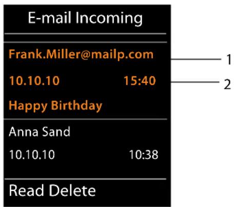
1 E-mail address or name transmitted by the sender (abbreviated if necessary) Bold: New message.
All e-mail messages that were not present in the incoming e-mail server when the inbox was last opened are identified as "new". All other e-mails are not marked, regardless of whether or not they have been read.
2 Date and time of receipt of e-mail message
If the inbox on the POP3 server is empty, No entries will appear in the display.
Please note
Many e-mail providers activate spam protection measures by default. E-mail messages classified as spam are stored in a separate folder and are therefore not shown in the incoming mail list.
Some e-mail providers allow you to deactivate spam protection or show spam e-mails in the incoming mail list.
Other e-mail providers may send a message to the inbox when a new spam e-mail is received. This is to inform you that a suspected spam e-mail has been received.
The date and sender of this mail are repeatedly updated, so that it is always displayed as a new message.
Messages when establishing a connection
The following problems may occur when connecting to the POP3 server. The messages are shown in the display for a few seconds.
Server not accessible
The connection to the POP3 server could not be established. This may have the following causes:
- Incorrect entry for the name of the POP3 server ( → Web configurator, page 106).
- Temporary problems with the POP3 server (server is down or is not connected to the Internet).
▶ Check settings in the Web configurator.
▶ Try again later.
Currently not possible
The resources your phone requires to make the connection are busy, e.g.:
– The maximum permitted number of VoIP connections has already been reached.
- One of the registered handsets is currently connected to the POP3 server.
▶ Try again later.
Logon at mail server failed
Error when logging in to the POP3 server. This may have the following cause:
- Incorrect entries for name of POP3 server, username and/or password.
▶ Check settings (→ Web configurator).
Mailbox parameters incomplete
Incomplete entries for name of POP3 server, username and/or password.
▶ Check/add to settings (→ Web configurator).
Viewing the message header and text of an e-mail
Prerequisite: You have opened the incoming mail list ( → page 55).

Select an e-mail entry.

Press the display key.
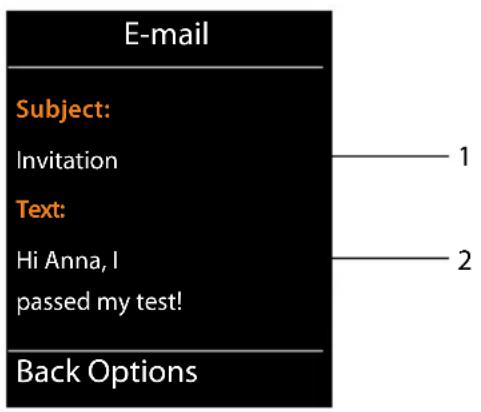
The subject of the e-mail (maximum 120 characters) and the first few characters of the text are displayed.
Example display on the Gigaset SL610 PRO handset:
flowchart
graph TD
    A["E-mail"] --> B["Subject:"]
    B --> C["Invitation"]
    B --> D["Text:"]
    D --> E["Hi Anna, I passed my test!"]
    D --> F["Back Options"]
    style A fill:#000,stroke:#fff,color:#fff
    style B fill:#ff0000,stroke:#000
    style C fill:#ff0000,stroke:#000
    style D fill:#ff0000,stroke:#000
    style E fill:#ff0000,stroke:#000
    style F fill:#ff0000,stroke:#000
1 Subject of the e-mail message. A maximum of 120 characters are displayed.
2 Text of the e-mail message (abbreviated if necessary).

Press the end call key to return to the incoming message list.
Please note
If the e-mail does not contain any standard text, the message View of E-mail not possible will briefly appear.
Viewing e-mail sender's address
Prerequisite: You have opened the e-mail notification to read it (→ page 57).

The sender's e-mail address is displayed, over several lines if necessary (maximum 60 lines).
Back Press the display key to return to the incoming message list.
Example display on the Gigaset SL610 PRO handset:

Deleting e-mail messages
Prerequisite: You have opened the incoming e-mail list ( → page 55) or the header or sender's address for an e-mail is displayed ( → page 57):

Yes Press the display key to confirm the security prompt.
The e-mail is deleted from the POP3 server.
Info Center – continuous Internet access from your phone
You can use your phone to retrieve online content from the Internet, i.e., request info services that are provided specifically for the telephone. The info services available are constantly updated.
Please note
You can launch the Info Center and display info services with every registered Gigaset SL610 PRO, C610H, SL78H, SL400H, S79H and S810H handset.
With some of these handsets, you can launch the Info Center directly from the main menu. For others (e.g., Gigaset C610H), you will find the Info Center in the submenu
★ Additional Features.
Configuring your own applications/info services
You can select info services (applications, apps) made available by the server.
Starting the Info Center, selecting info services
e.g., on the Gigaset SL610 PRO, S79H, S810H and SL400H handsets:
Info Centre
e.g., on the Gigaset C610H handset:
→ ★ Additional Features → Info Centre
Your Info Center menu i.e., a list of available info services is displayed. You can navigate between the info services.
Select the info service and press OK.
To access certain info services (personalised services), you have to log in with an authentication name and password. In this case, enter your access data as described in the "Logging in for personalised info services" section on page 60.
Messages when loading requested information
The information is loaded from the Internet. Wait a few seconds until the information is displayed. The display shows Please wait ....
If the information for an info service cannot be displayed, one of the following messages appears:
Requested page cannot be reached
Possible causes of this are:
◆ Time limit exceeded (timeout) when loading the information
◆The Internet server for the info services cannot be accessed.
▶ Check your Internet connection and repeat the request at a later date.
Info Center – continuous Internet access from your phone
Coding error on requested page
The content of the requested info service is coded in a format that the handset cannot display.
Unable to show requested page
General error when loading the info service.
Authorization Failed
Login has failed. Possible causes of this are:
◆You have not entered your authentication data correctly.
▶ Reselect the info service and repeat the login process. Please remember that data is case sensitive.
◆You are not entitled to access this info service.
Logging in for personalised info services
If a special login process with username and password is required to access an info service, the following is displayed after the service has been called up:
Authent. Name
Enter the username supplied by the provider of the info service.
Save Press the display key.
Authent. Password
Enter the password associated with this username.
Save Press the display key.
If login was successful, the requested info service is displayed.
If login failed, a message to this effect appears on the display → Messages when loading requested information, page 59.
Please note
Please remember that authentication data is case sensitive. General instructions on entering text can be found in the handset user manual.
Operating the Info Center
Depending on the type of info service requested, you can perform the following operations:
Scrolling within an info service
▶ You can use □ to scroll downwards within an info service, and ▲ to scroll up (back).
Skipping back to the previous page
▶ Press the left display key.
Skipping back to the Info Center menu
▶ Briefly press the end call key ☐.
You want to go offline:
Press and hold the end call key ☐; the handset returns to idle status.
Selecting a hyperlink
Hyperlink to further information:
If the page contains a hyperlink to further information, this is indicated by the ▶ icon.
If a page with hyperlinks is opened, the first hyperlink is highlighted.
▶ Using the control keys (☐ and/or ▲) as required, you can navigate to the hyperlink that you would like to select. The hyperlink is then highlighted by bars.
▶ Press the right display key Link to open the relevant page.
Hyperlink to a phone number:
If a hyperlink contains a phone number, you can copy the number to the local directory or call the number directly (Click-2-Call functionality).
▶ Select the hyperlink using the □ and/or ▲ keys, as required.
▶ You can identify a hyperlink of this type by the fact that Call is shown above the right display key.
▶ Press the display key → to copy the phone number to the local directory on your handset.
Or:
▶ Press Call to call the stored number.
Depending on the provider, if you press Call,
◆The number is dialled directly
◆ The number appears first in the display, in which case you must first confirm the number before it is dialled.
▶ If you press Yes, the number is dialled.
Or:
▶ If you press No, the page is displayed again with the hyperlink. The number will not be dialled.
Entering text
If necessary, use [◀] to navigate to the line containing the field into which you want to enter text. The cursor flashes in the text field.
▶ Enter the text using the keys on your handset.
▶ If necessary, navigate to other text fields to complete them or make a selection (see below).
▶ Press the right display key to complete the entry and send the data.
Making selections
▶ If necessary, use 🔒 to navigate to the line in which you would like to make a selection.
▶ Press left or right on the control key several times to make the required selection.
▶ Use [◀] to navigate to other selection fields and make your selection as described above.
▶ Press the left display key to complete the selection and send the data.
Setting options
▶ Use [◀] to navigate to the line containing the option. The line is highlighted.
▶ Activate or deactivate the option via the control key ▶ (press right) or the left display key (e.g., OK).
▶ If necessary, navigate to other options or text fields to set or complete them.
▶ Press the left display key (e.g., Send) to complete the entry and send the data.
Displaying information from the Internet as a screensaver
You can configure your handset to display one of the info services from the Info Center (e.g., weather reports, news feeds) in the device's idle display.
To do so on a Gigaset SL610 PRO, C610H, SL78H, SL400H, S79H or S810H handset, for example, you must activate the Info Services screensaver.
The text information appears on the display approximately ten seconds after the handset returns to idle status.
Depending on the information feed selected, a display key appears on the right of the screensaver.
▶ Press the right display key to call up further information.
▶ Press and hold the end call key 🔍 to return to idle status.
Selecting information for the screensaver
The default setting for the Info Services screensaver is the weather forecast. You can change this setting on the handset via the Info Center.
When the handset is in idle status:
→ ★ Additional Features → Info Centre or → Info Centre
The menu for your Info Center appears.


Select Screensaver and press OK.
Select the information service for the Info Services screensaver.
Scroll to the next line, if necessary, and make further settings for the information service selected.
Save Press the display key.
Some providers offer answering machines on the network – network mailboxes.
Each network mailbox accepts incoming calls made via the corresponding line (VoIP phone number). To record all calls, you should therefore set up a network mailbox for each of your VoIP phone numbers.
You can activate/deactivate the network mailboxes using the handset or the Web configurator. To do this, you only require the phone number of the network mailbox.
Activating/deactivating network mailboxes, entering numbers
On the handset, you can manage the network mailboxes that are assigned to one of its receive connections.
→ Voice Mail → Network Mailboxes
The list of connections that are assigned to the handset as receive connections is displayed. Net AM: xxx is displayed, where xxx is replaced by the respective default connection name (Net AM: IP1 to Net AM: IP6).
If several receive connections are assigned to the handset, select connection and press OK.
▶ You can enter data in the following fields:
Status
Select On to activate the network mailbox. Select Off to deactivate.
Network Mailbox
The number that is currently stored for the network mailbox is displayed.
Enter or change the phone number for the network mailbox if necessary.
With some VoIP providers your network mailbox phone number is downloaded together with the general VoIP provider data, saved to your base and displayed under Network Mailbox.
▶ Press the display key Save.
Configuring a network mailbox for fast access
With fast access you can dial a network mailbox directly.
Assigning key 1, changing assignment
Fast access settings are handset-specific. You can assign a different network mailbox to key 1∞ on each registered handset.
No answering machine is preconfigured for fast access in the default settings.
1 ☉ Press and hold key 1 ☉.
Or:
→ Voice Mail → Set Key 1
The list of VoIP connections that are assigned to the handset as receive connections is displayed. Net AM: xxx is displayed, where xxx is replaced by the respective default connection name (Net AM: IP1 to Net AM: IP6).

Select entry and press Select (○ = on).
If a number is already stored for this network mailbox, fast access is activated immediately.

Press and hold the end call key (idle status).
If no number is saved for the network mailbox, you are asked to enter the number of the network mailbox.

Jump to the Network Mailbox line.

Enter the number for the network mailbox.

Press the display key.

Press and hold the end call key (idle status).
Fast access is activated.
Please note
You can only assign fast access to one network mailbox.
You can also call the network mailbox for a handset's receive connections directly via the message key ( → page 66).
Calling the answering machine via fast access

Press and hold.
If you have set a network mailbox for fast access, you are connected directly to this network mailbox.

If necessary, press the speaker key.
You hear the network mailbox announcement.
Displaying new messages in the handset's idle display
If a new message is present on one of the network mailboxes assigned to the handset via its receive connection, or on the local answering machine, the symbol 🔐 and the number of new messages are generally shown on the idle display. The ☑ message key flashes.
Calling the network mailbox using the message key
Under the message key ☑ you will find a list for each network mailbox that fulfils the following prerequisites:
◆ The corresponding connections are assigned to the handset as receive connections.
◆The network mailbox phone number is saved on the phone.
You can use the list to call the network mailboxes directly and listen to the messages.
Press the message key.
The following is displayed (Gigaset SL610 PRO as an example):

1 Mailbox IP 1:, Mailbox IP 2: and so on are the network mailboxes for the VoIP connections. "IP1", "IP2" and so on are the default names of the corresponding VoIP connections. The default names are always displayed regardless of which connection name you specified during configuration.
2 If there are new messages in the network mailbox, the list entry is shown in bold. The number of new messages is shown in brackets following the list entry.
3 If there are no new messages, no number is shown after the list entry for the network mailbox. The number of messages stored in the network mailbox is not displayed.
Mailbox IP 1: / Mailbox IP 2: / ... / Mailbox IP 6:
Select the network mailbox entry and press OK.
You are connected directly to the network mailbox and hear its announcement. Messages can generally be played back using your handset keypad (digit codes). Listen to the announcement.
Please note
◆ The network mailbox is automatically called via the corresponding connection. An automatic area code specific to your phone is not prefixed.
◆ Network mailbox messages can generally be played back using your phone's keypad (digit codes). For VoIP, you need to define how the digit codes should be converted to DTMF signals and transmitted (→ page 103).
Ask your VoIP provider which type of DTMF transmission it supports.
You are helping to protect the environment with your Gigaset.
Reducing energy consumption
Your telephone has a power-saving adapter plug and uses less power.
Reducing radiation
The radiation from your telephone is reduced automatically: the closer the handset is to the base, the lower the radiation.
You can reduce the radiation from the handset and the base even more by using Eco Mode:
Eco Mode
Reduces the radiation of the base and handset by 80% – whether you are making a call or not. Eco Mode reduces the range of the base by approx. 50%. It is always better to use Eco Mode when a reduced range is sufficient.
Switching off radiation
◆Eco Mode+
When you activate Eco Mode+, the radiation (DECT transmission power) of the base and handset is switched off automatically and only turns on when calls are made. This is also true when multiple handsets are used, if the handsets support Eco Mode+.
Eco Mode/Eco Mode+ can be activated/deactivated independently of one another and can also be used with multiple handsets.
Activate/deactivate Eco Mode/Eco Mode+:
→ Settings → Eco Mode → Eco Mode / Eco Mode+
Change Press the display key (☑ = on).
If Eco Mode / Eco Mode+ is activated/deactivated, this will normally be indicated in the display of the connected handset.
Status displays on the Gigaset SL610H PRO/C610H handset
| Display icon | |
| Reception strength:– Good to poor– No reception | |
| white Eco Mode | de deactivated |
| green Eco Mode | de enabled |
| white Eco Mode+ | enabled(displays instead of the reception strength icon when in idle status) |
| green | Eco Mode and Eco Mode+ enabled |
Please note
When using Eco Mode+, you can ensure that the range of the base is sufficient by pressing and holding the talk key ☐. You hear the dial tone if the base can be reached.
◆ When Eco Mode+ is enabled:
- Call setup is delayed by approx. 2 seconds.
- Handset standby time is reduced by approx. 50% .
◆ Registering handsets that do not support Eco Mode+ causes the mode to be deactivated on the base and all other handsets.
◆ Activating Eco Mode reduces the range of the base.
◆ Eco Mode / Eco Mode+ and repeater support (→ page 83) cancel each other out, i.e., if you use a repeater, you cannot use Eco Mode and Eco Mode+.
You can register up to six handsets and six Gigaset repeaters to your base.
Each registered device is assigned an internal number (1–6) and an internal name (INT 1–INT 6). You can change the number assignment and names.
If you register a seventh handset the last registered handset will be de-registered automatically.
When you register a Gigaset handset, the base transfers entries for the following online directories to the local directory on the handset to enable you to use the online directories on your new handset as well.
Prerequisite: The handset can send and receive directory entries (see handset user manual).
◆ The currently set online directory (→ page 106) with a provider-specific name.
◆ The currently set Yellow Pages (→ page 106) with a provider-specific name.
◆ The currently set private net directory named Prv.NetDir.
Successful registration is acknowledged briefly with the message Data Transfer x entries received for this reason.
Registering handsets
You can register up to six handsets to your base.
You must register the handset manually on both the handset (1) and the base (2).
Once registration is complete, the handset returns to idle status. The handset's internal number is shown in the display, e.g., INT 1. If not, repeat the procedure.
You can register other Gigaset handsets and handsets for other devices with GAP functionality as follows:
1) On the handset
Start to register the handset as described in its user manual.
On the Gigaset SL610 PRO handset, for example:
The handset is not registered to a base:
Register Press the display key.
The handset is already registered to a base:
☐ → ⚫ Settings → Registration → Register Handset
If the handset is already registered to four bases:


Select base, e.g., Base 3 and press OK.
Enter the system PIN for the base, if required, and press OK.
A message appears stating that the handset is searching for a base that is ready for registration.
2) On the base
Within 60 seconds, press and hold the registration/paging button on the base ( → page 3) (for approx. 3 seconds).
Please note
All base connections are assigned to a handset as receive connections as soon as registration is complete. The first configured VoIP connection is assigned to the handset as a send connection. You can change the assignment → page 81.
Assigning the internal number
The base assigns the handset the lowest free internal number (possible numbers: 1–6). The internal number appears in the handset's display, e.g., INT 2. This means that the internal number 2 has been assigned to the handset.
De-registering handsets


Settings → Registration → De-reg. Handset

Select the internal party you wish to de-register and press OK. (The handset you are currently using is highlighted with <).

If the system PIN is not 0000: enter the current system PIN and press OK.

Press the display key.
Locating a handset, finding the phone's IP address ("paging")
You can locate your handset using the base.
▶ Briefly press the registration/paging button on the base (→ page 3).
All handsets will ring at the same time ("paging"), even if the ringtones are switched off. The current (local) IP address for the base appears in the handset displays.
(e.g., on the Gigaset SL610 PRO).

Ending paging
▶ Briefly press the registration/paging button on the base (→ page 3).
Or:
▶ Press the talk key 📊 on the handset.
Or:
▶ Press the display key Silence on the handset.
Or:
▶ Do not press any key on the base or handset: After approx. 30 seconds, the paging call will end automatically.
Please note
◆An incoming external call will not interrupt the paging process.
◆ If there are already two internal connections between the handsets, then paging is not possible.
◆ A paging call is also signalled acoustically on handsets where the ringtone is permanently deactivated.
Making internal calls
Internal calls to other handsets registered on the same base are free.
Calling a specific handset

Initiate internal call.

Enter the number of the handset.


Initiate internal call.

Select
handset.

Press the talk key.
You hear the busy tone if:
◆There are already two internal connections.
◆ The handset being called is not available (deactivated, outside range).
◆The internal call is not accepted within three minutes.
Calling all handsets ("group call")

Press briefly to initiate an internal call.

Press the star key.
Or

Press briefly to initiate an internal call.
Call All
Select and

Press the talk key.
Or

Press and hold.
All handsets are called.
Ending a call

Press the end call key.
Transferring a call to another handset
You can transfer (connect) an external call to another handset.
You are conducting an external call:

Open the list of handsets.
The external party hears music on hold, if activated ( → page 78).

Select a handset or Call All and press OK.
When the internal party answers:
▶ If necessary, announce the external call.

Press the end call key.
The external call is transferred to the other handset.
If the internal party does not answer or the line is busy, press the display key End to return to the external call.
When transferring a call, you can also press the end call key ☐ before the internal party answers.
If the internal party does not answer or the line is busy, the call will automatically return to you.
Initiating an internal consultation call/conference
When you are conducting an external call, you can call an internal participant at the same time for consultation or hold a conference call between all three participants.
When you are conducting an external call:

Open the list of handsets.
The external party hears music on hold, if activated ( → page 78).

Select handset and press OK.
You are connected to the internal participant.
Either:

→ End Active Call
You are reconnected with the external participant.
Or:

Press the display key.
All three participants are connected with each other.
If the internal participant does not answer:
▶ Press the display key End to return to the first external caller.
Ending a conference call

Press the end call key.
If an internal participant presses the end call key ☐, the other handset remains connected to the external participant.
External call waiting during an internal call
If you receive an external call during an internal call, you will hear the call waiting tone (short tone). The caller's number or name appears in the display if Calling Line Identification is enabled.
You have the following options:
Rejecting the external call
Reject Press the display key.
The call waiting tone is turned off. You remain connected with the internal participant. The external caller will hear the busy tone.
Accepting an external call/putting an internal party on hold
Accept Press the display key.
You are connected to the external caller. The internal call is placed on hold.
You have the following options:
◆Swap between both participants:
▶ Use [◀] to switch between the participants (call swapping).
◆Speak to both participants at the same time:
▶ Press the display key Confer. to establish the conference call. Press the display key End Conf. to return to call swap mode.
Ending an internal call
Press the end call key.
The external call is signalled as an incoming call. You can accept the call ( → page 37).
Internal call waiting during an internal/external call
If an internal party attempts to call you while you are involved in an external or internal call, this call is shown on the display (internal call waiting). You can either accept or reject this call.
Press any key to make this prompt disappear from the display.
You must end the current call to accept the internal call. Then the internal call is signalled as per usual. You can accept the call.
Changing the name of an internal party
The names "INT 1", "INT 2" etc. are assigned automatically on registration. You can change these names. The name must be no more than 10 characters. The changed name is displayed in every handset's list.
Open the list of handsets. Your own handset is indicated by
Select handset.
Options Open menu.
Rename
Enter the name. Save Press the display key.
Changing the internal number of an internal party
A handset is automatically assigned the lowest free internal number from 1–6 during registration. If all numbers are in use, then the number 6 is overwritten as long as this handset is in idle status. You can change the internal numbers of all registered handsets (1–6).

Open the list of handsets. Your own handset is indicated by


ions Open menu.
Assign Handset No.
Select and press OK.

Select the handset, if necessary.

Select or enter the internal number.

Switch to another handset, if necessary, and select the number etc.

Press the display key to save the entry.
You will hear the error tone if an internal number has been assigned twice.
▶ Repeat the procedure with a free number.
Your Gigaset comes preconfigured. You can change the settings via the menu on a connected Gigaset handset, e.g., from a Gigaset SL610 PRO, C610H, SL78H, SL400H, S79H or S810H. The following instructions are based on a Gigaset SL610 PRO handset.
Some settings can also be carried out via the phone's Web configurator ( → page 87).
Setting the date/time
The date and time must be set in order to show the correct time for incoming calls, for example.
There are two methods of setting the date and time:
- Your base receives the date and time from a time server on the Internet, providing that the base is connected to the Internet and synchronisation with a time server is enabled (default setting; → page 106).
- You can also change the date and time manually via the menu on one of the registered handsets.
Your base accepts the new time and transfers this information to the connected handsets.
Setting the date and time on the handset
If the date and time have not yet been set on the handset, the Set Time display key appears.
Set Time Press the display key.
Or:
→ Settings → Date/Time
▶ You can enter data in the following fields:
Date:
Enter the day, month and year as an 8-digit number via the keypad, e.g., 1∞ 4 GHI 0 ∩ 1∞ 2 ABC 0 ∩ 1∞ 1∞ for 14 January 2011.
Time:
Enter the hours and minutes in 4-digit format via the keypad, e.g., 0 → 7 PQRS 1 → 5 JKL for 07:15 am.
▶ Press the display key Save to save the settings.
Quickly accessing functions
Prerequisite: The handset used supports the individual assignment of display keys in idle status.
▶ Press and hold the left or right display key. The list of possible key assignments is opened.
▶ Select a function and press OK.
Configuring the system settings
The following base functions can also be selected in addition to the functions provided by the handset for assigning display keys:
Withhold Number
Withhold the phone number for the next call ( → page 44).
Opens the e-mail submenu for receiving and reading e-mail notifications
(→ page 55):
→ Messaging → E-mail
More Functions...
Select and press OK; you can then also select from the following base functions:
Send Connection
Assign an alternative send connection to a key.
▶ Select a connection as a (further) send connection for the handset from the list of connections and press OK.
Press this display key if the alternative send connection should be used (temporarily) for the next call (instead of the send connection for the handset).
Connect. Selection
Assign the list of connections for your phone to a key.
Select the send connection for each call from the list ( → page 36).
Call Lists
Assign the call lists menu to a key.
→
Call Lists
Withhold Number
Withhold the phone number for the next call ( → page 44).
Call Divert
Assign the menu for setting and activating/deactivating call divert to a key (→ page 42):
Prerequisite: The provider supports call divert.
→
Select Services → Call Divert
Opens the e-mail submenu for receiving and reading e-mail notifications
(→ page 55):
→
□Messaging → E-mail
Info Centre
Start the Info Center and open the list of available information services – go online ( → page 59).
→ Additional Features → Info Centre
The selected function is displayed in the bottom display line above the display key (abbreviated if necessary). To start the function, you then simply need to press the button.
Starting a function
When the handset is in idle status:
▶ Press the display key briefly.
The submenu opens and the function is performed.
Protecting the telephone from unauthorised access
Protect the phone system settings with a system PIN known only to you. You have to enter the system PIN if you register or de-register a handset, change local network settings, perform a firmware update or reset the phone to default settings.
Changing the system PIN
You can change the phone's 4-digit system PIN (default setting: 0000) to a 4-digit PIN known only by you.
☐ → ⚫ Settings → System → System PIN
If the current system PIN is not 0000: Enter the current system PIN and press OK.
Enter new system PIN.
OK Press the display key.

Setting your own area code
Your area code (international and local area code) must be saved on the phone before you can transfer phone numbers (e.g., in vCards).
Some of these numbers are already preset.
→ Settings → Telephony → Area Codes
Check that the (pre)set area code is correct.
▶ You can enter data in the following fields:
Select/change input field.
Navigate in the input field.
<C If necessary, delete number: press the display key.
Enter number.
Save Press the display key.
Example:
![Area Codes International Code: 00 - 4 Local Area Code: 0 - [ ] < C Save](/content/2026/06/1283891/images/92560d973f6ca73f5f55642d68a6bdc0bc20a6a4ddb9694c6c00a86a31265fe3.jpg)

Activating/deactivating music on hold
☐ → ⚫ Settings → Audio Settings → Music on Hold
Press Change to activate or deactivate the music on hold (☑ = on).
Setting the base's IP address in the LAN
Prerequisite: Your base is connected to a router or a PC ( → page 10).
An IP address is required in order for the LAN to "recognise" your phone.
The IP address can be assigned to the phone automatically (by the router) or manually.
If done dynamically, the router's DHCP server automatically assigns an IP address to the phone. The base's IP address can be changed according to router settings.
With manual/static assignment, you assign a static IP address to the phone. This may be necessary depending on your network configuration (e.g., if your phone is connected directly to a PC).
Please note
To assign the IP address dynamically, the DHCP server on the router must be activated. Please also read the user manual for your router.
→ Settings → System → Local Network
If the system PIN is not 0000: enter the system PIN and press OK.
▶You can enter data in the following fields:
IP Address Type
Select Static or Dynamic.
For IP Address Type Dynamic:
The following fields show the current settings that the phone obtained from the router. These settings cannot be changed.
For IP Address Type Static:
You must manually define the IP address and the subnet mask for the phone as well as the default gateway and DNS server in the following fields.
For IP Address Type Static:
IP Address
Enter the IP address that is to be assigned to the phone (overwriting the current settings).
The default is 192.168.1.2.
For information on the IP address, see the glossary ( → page 127).
Subnet Mask
Enter the subnet mask to be assigned to the phone (overwriting the current settings).
The default setting is 255.255.255.0
For information on the subnet mask, see the glossary ( → page 132).
DNS Server
Enter the IP address for the preferred DNS server. The DNS server (Domain Name System, → page 124) converts the symbolic name of a server (DNS name) into the public IP address for the server when the connection is made.
You can specify your router's IP address here. The router forwards phone address requests to its DNS server.
The default is 192.168.1.1.
Default Gateway
Enter the IP address for the default gateway ( → page 126) through which the local network is connected to the Internet. This is generally the local (private) IP address for your router (e.g., 192.168.1.1). Your phone requires this information to be able to access the Internet.
The default is 192.168.1.1.
▶ Press Save to save the settings.
Please note
You can also make local network settings via the Web configurator ( → page 97).
Configuring VoIP connections
You can configure up to six VoIP connections on your telephone, i.e., you can assign up to six VoIP phone numbers to your phone.
You need to set up an IP account (VoIP account) with a VoIP provider for each connection. You must save the access data for this IP account on your phone. The IP wizard will help you to do this.
Launching the IP wizard:
→ Settings → Telephony → VoIP Assistant
You will see the following in the display:
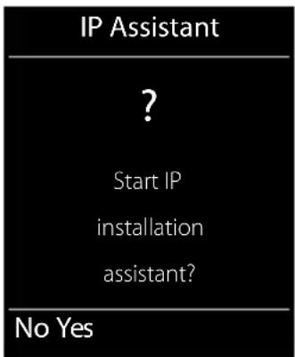
The procedure for the IP wizard is described on page 18.
Each time you run the IP wizard you can configure/reconfigure one VoIP connection (IP account).
▶ Restart the IP wizard if you wish to configure/reconfigure another VoIP connection.
Please note
You can also use the Web configurator to configure and manage VoIP connections ( → page 99).
Automatic update for the VoIP provider settings
After the first download of the VoIP provider settings, your phone will check daily whether a newer version of the file for your VoIP provider is available from the Internet on the configuration server.
Auto configuration has been used to download VoIP settings (→ page 17)
If there is new configuration data, this is automatically downloaded to your phone (without notification).
Manual VoIP configuration with the VoIP wizard
If there is new provider data, the idle display on the handset displays the message New profile available..
Yes Press the display key to confirm the prompt.

Enter the system PIN if necessary and press OK.
The new data for your VoIP provider will be downloaded and saved on the phone.
If you answer the prompt with No, the phone returns to idle status. Your telephone will not remind you of this new profile again. The message will only be shown again if a newer version of the provider data is available.
A profile update will only be started if no other profile or firmware update is taking place at the time.
Assigning send and receive connections to internal parties
If you have several connections configured for your telephone system, you can do the following for each internal party:
◆ Assign a send connection or allow the internal party to select the line for each external call (select line).
◆ Assign one or several receive connections. Only calls received via one of the assigned connections are signalled on the device.
Assigning a send connection
Prerequisite: You have configured at least one VoIP connection on your phone.
→ Settings → Telephony → Send Connections
A list of handsets is displayed.
Select the handset that should be assigned a new send connection and press the display key OK.
Choose Sel. at each call or a connection as the send connection. All configured connections are displayed with the names you have set.
Save Press the display key to save the changes.
Sel. at each call is only offered if more than one connection is configured.
If you select Sel. at each call, you can select the connection you want to use for each call you make.
Please note
If the send connection on a handset is deleted or deactivated, the first configured VoIP connection is assigned to it as the send connection.
Assigning receive connection(s)
Prerequisite: Several connections are configured for your phone.


Settings → Telephony → Rec. Connections
A list of internal parties (handsets) is displayed.

Select the internal parties that should be assigned new receive connections and press the display key OK.
A list containing all configured connections is opened. You can select Yes or No for each connection.

Select Yes if you want the relevant connection to be the receive connection for the internal party. Select No if it should not be the receive connection.

Change to the next connection.
▶ Repeat these two steps for each connection.
▶ Press the display key Save to save the changes.
Please note
◆ If a new connection is configured, it is assigned as the receive connection to all internal parties and Answer Machine 1.
If a connection is not assigned as the receive connection to any internal party, calls on this connection will not be signalled.
Updating the phone firmware
Prerequisite: The phone is connected to the Internet (i.e., connected to a router, → page 12).
If necessary, you can update your phone's firmware.
The firmware update is downloaded directly from the Internet by default. The relevant Web page is preconfigured in your phone.
Prerequisite:
The phone is in idle status i.e.,
◆No calls are being made.
◆There is no internal connection between the registered handsets.
◆The base menu is not open in any of the handsets.
Starting the firmware update manually


Settings → System
Update Firmware
Select and press OK.

Enter the system PIN and press OK.
The phone establishes a connection to the Internet.

Press the display key to start the firmware update.
Please note
◆ The firmware update can take up to six minutes, depending on the quality of your DSL connection.
When updating from the Internet, checks are made to ensure that no newer version of the firmware exists. If this is not the case, the operation is terminated and a message is issued to that effect.

Repeater support
You can increase the range and signal strength of your phone using a repeater. You will need to activate repeater mode. This will terminate any calls that are in progress at the time.
Prerequisite: Eco Mode(+) is deactivated.

→ Settings → System → Repeater Mode
Change
Press the display key to activate or deactivate repeater mode (☑ = on).
Yes
Press the display key to confirm the prompt.
Please note
◆ Repeater support and Eco Mode / Eco Mode+ (→ page 67) cancel each other out, i.e., both functions cannot be used at the same time.
◆ The default encrypted transmission setting is deactivated when repeater mode is activated.
Restarting the base
When the handset is in idle status:

→ Settings → System → Base Restart
The firmware for the base is then restarted. This process takes about 20 seconds.
Resetting the base to the default settings
The individual settings are reset.
Resetting the base via the menu
When the settings are restored:
◆Handsets are still registered
◆The system PIN is not reset.
The following settings in particular are reset to the default settings (you can change the settings marked "*" via the Web configurator):
◆The entered VoIP connections (are deleted)
◆The assignment of send and receive connections
◆Audio settings for VoIP connections *
◆DTMF settings *
◆Own area code
◆Settings for the local network
◆The names of the handsets
◆Eco Mode and Eco Mode+ are deactivated
◆PABX connection settings
◆ Digit and display key assignments as well as the 1 ∞ key
◆Settings for select services: call divert
Call lists are deleted.

→ Settings → System → Base Reset

Enter the system PIN and press OK.

Press the display key.
After the reset, the base is restarted. The restart takes around ten seconds.
The installation wizard is launched ( → page 16).
Resetting the base using the button on the base
As with resetting the base via the menu, all individual settings are reset. The system PIN is also reset to 0000 and all handsets registered above and beyond the scope of delivery will be de-registered.
Please note
For instructions on re-registering the handsets after a reset (where applicable)
→ page 69.
▶ Remove the cable connections from the base to the router ( → page 12).
Remove the base power adapter from the socket ( → page 11) if connected.
▶ Press and hold the registration/paging button (→ page 3).
▶ For PoE (Power over Ethernet): reconnect the base to the router.
If no PoE: plug the power adapter back into the socket.
▶ Press and hold the registration/paging button (at least 20 seconds).
▶ Release the registration/paging button. The base has now been reset.
Checking the base MAC address
Depending on your network configuration, you may have to enter your base MAC address in your router's access control list, for example. You can check the MAC address on the handset.
In idle status:

Open
menu.

Press keys in sequence.
The MAC address is displayed.
Back Return to idle status.
Connecting the phone to a PABX
The following settings are only necessary if your PABX requires them; see the PABX user manual.
Saving an access code (outside line code)
You may have to enter an access code in front of the phone number for external calls (outside line code, e.g., "0"). Prerequisite: You must enter an access code in front of the phone number for external calls using your PABX, e.g., "0" 12120098.
→ Settings → Telephony → Access Code
▶ You can enter data in the following fields:
Access external IP line with:
Enter or change access code, max. 3 digits.
For:
Specify when the access code should also be dialled when dialling via VoIP:
Call Lists
For dialling from the missed calls list, accepted calls list or an answering machine list.
All Calls
For all numbers dialled on the handset.
Off
No access code should be dialled first for calls via a VoIP connection.
Save Press the display key.
Configuring the phone via the Web configurator
The Web configurator for your Gigaset telephone enables you to change the settings for your phone conveniently on your PC.
Alternatively, you can change the settings that are also available on a registered Gigaset telephone handset via the Web browser on your PC, e.g., configuring VoIP connections, downloading firmware updates or starting Eco Mode.
- You can change additional settings that are not possible via a registered handset, e.g., meeting particular prerequisites for connecting the phone to a company network or adjusting the voice quality on VoIP connections.
On the base, you can save data that is required to access specific services on the Internet. These services include access to public and private online directories, to the POP3 server for your e-mail account and synchronising the date/time with a time server.
- You can save configuration data for your telephone as files on your PC and reload these onto your telephone in the event of an error.
- You can manage the directories on registered Gigaset handsets (save to PC, compare them with one another or against a directory on your PC).
Below you will find a list of the Web configurator functions and the navigation paths to the Web configurator pages where the functions are available. See the online Help for the Web configurator ( → page 93) for a detailed description of the Web pages and the required entries.
Connecting the PC with the telephone's Web configurator
Prerequisites:
◆ A standard Web browser is installed on the PC, e.g., Internet Explorer version 7.0 or higher, Firefox version 4.0 or higher or Apple Safari version 5.0 or higher.
◆ The phone and PC are directly connected with each other via a router. The settings of any existing firewall installed on your PC allow the PC and phone to communicate with each other.
Please note
◆ Depending on your VoIP provider, it is possible that you will be unable to change individual settings in the Web configurator.
◆ The phone is not blocked while you select your settings in the Web configurator. You can make calls with your phone or modify settings at the same time.
◆ While you are connected to the Web configurator, it is blocked to other users. It cannot be accessed by more than one user at any one time.
Establishing a connection via the phone's IP address
▶ Determining a telephone's current IP address via one of the registered handsets:
You can see the phone's current IP address in the handset display by briefly pressing the registration/paging button on the base.
Your phone's IP address can change if you have activated dynamic IP address assignment ( → page 78).
Warning
If one of the four parts of the IP address contains leading zeros (e.g., 002), these zeros must not be entered in the Web browser address field. Otherwise, the Web browser will not be able to establish a connection to the Web configurator.
Example: The IP address 192.168.002.002 is displayed on the phone. 192.168.2.2 should be entered in the address field.
▶ Launch the Web browser on your PC.
▶ Enter http:// and the telephone's current IP address (for example: http://192.168.2.2) into the address field of the Web browser.
▶ Press the return key.
A connection is established to the phone's Web configurator.
Please note
The connection between the PC and the Web configurator is a local connection (LAN connection). The Internet is only accessed to establish the connection.
Logging into/off the Web configurator
Prerequisite: Your PC and phone are connected to the Internet.
Logging in, setting the interface language
Once you have successfully established the connection, the Login Web page is displayed in the Web browser.

Picture 1 Home page
You can select the language you want the menus and Web configurator dialogs to be displayed in. The language that is currently selected is displayed in the first field on the Web page.
▶ If necessary, click to open the list of available languages.
▶ Select the language.
The Web page is reloaded in the selected language. Reloading may take some time.
Please note
The Web configurator Web pages for the required language are loaded onto the base from the configuration server. For this reason, you can only change the language if your device is connected to the Internet.
▶ Enter your phone's system PIN (default setting: 0000) in the bottom field of the Web page to access the Web configurator functions.
▶ Click OK.
Once you have successfully logged in, the Home Web page opens with general information on the Web configurator.
If you enter an incorrect system PIN, a corresponding message is displayed. You are prompted to re-enter the PIN.
If you enter an incorrect system PIN a second time, the PIN field is blocked for a short time (greyed out). The duration of the block will double each time a PIN is subsequently entered incorrectly.
Please note
If the system PIN is still set as 0000 on the phone (default setting), you will be notified during login that the device is not secure and you should change the PIN. You can deactivate this security advice for subsequent logins by selecting the option "Don't show this security advice again.". Click OK to close the dialog box.
If you do not make any entries for a lengthy period (approx. 10 minutes), you are automatically logged off. The next time you try to make an entry or open a Web page, the Login Web page is displayed. Re-enter the system PIN to log back in again.
◆ Any entries that you did not save on the phone before automatic logoff will be lost.
Logging off
In the menu bar (→ page 91) at the top right of every Web page in the Web configurator, you will see the Log Off command. Click Log Off to log off from the Web configurator.
Warning
Always use the Log Off command to end the connection to the Web configurator. If, for example, you close the Web browser without logging off beforehand, access to the Web configurator may be blocked for a few minutes.
Understanding the structure of the Web configurator pages
The Web configurator pages (Web pages) contain the UI elements shown in (example). Example of the structure of a Web configurator page:

flowchart
graph TD
    A["Home"] --> B["Settings"]
    B --> C["Status"]
    C --> D["Log Off"]
    D --> E["HelpButtons"]
    F["Working areaNavigation area Menu bar (tabs)"] --> G["Set"]
    F --> H["Cancel"]
    I["Network"] --> J["IP Configuration"]
    I --> K["Security"]
    I --> L["Telephony"]
    I --> M["Messaging"]
    I --> N["Directories"]
    I --> O["Management"]
Menu bar
The Web configurator menus are displayed in the form of tab pages in the menu bar.
The following menus are available:
Home
The home page opens once you have logged in to the Web configurator. It contains information on the Web configurator functions.
If no VoIP account exists yet, the home page provides access to the Quick Start Wizard, → page 96.
Settings
This menu allows you to make settings on your phone.
If you select the Settings menu, a list containing this menu's functions is displayed Quick Start Wizard the navigation area (→ page 91).
Status
This menu provides you with information about your phone.
Log Off
You will find the Log Off function to the right of the menu bar on every Web page.
Please note
For an overview of the Web configurator menus, see → page 95.
Navigation area
The functions of the menu ( → page 91) selected in the menu bar are listed in the navigation area.
If you select a function, the associated page containing information and/or input fields opens in the working area. The selected function is highlighted in orange.
If a function is assigned subfunctions, these are listed below the function as soon as you select the function (in the example Telephony).
The relevant page for the first subfunction (highlighted in orange) is displayed in the working area.
Network
Telephony
Connections
Audio
Number Assignment
Call Divert
Dialling Plans
Network Mailboxes
Advanced VoIP settings
Messaging
Directories
Management
Working area
Depending on the function selected in the navigation area, information or dialog boxes are displayed in the working area that allow you to make or change your phone settings.
Making changes
Make settings via input fields, lists or options.
◆ There may be restrictions regarding the possible values for a field e.g., the maximum number of characters, entering special characters or certain value ranges.
◆To open a list, click .You can choose between default values.
◆There are two kinds of options:
- Checkboxes: You can activate one or more options from a list. Active options are indicated by ☑ non-active options by . You can activate an option by clicking The status of the other options in the list does not change. You can deactivate an option by clicking ☑
- Alternative options (radio buttons): The active option in the list is indicated by , and the non-active by You can activate an option by clicking . The previously activated option is deactivated. You can only deactivate an option by activating another option.
Entering Cyrillic and Turkish characters
In the following section, the specified maximum number of characters permitted in a field refers to Latin characters and digits (1 character = 1 byte), i.e., 1 character means 1 byte.
Cyrillic and Turkish characters require 2 bytes each, e.g., with a field length of 16 characters, you can enter a maximum of eight Cyrillic or Turkish characters.
If you enter too many characters into a field, the entry is rejected (not saved in the phone). The "old" field content (or the default settings) is retained and displayed again when the Web page is updated. No warning/confirmation is given.
Applying changes
As soon as you have made your change on a page, save and activate the new setting on the phone by selecting Set.
If your entry does not comply with the rules for this field, an appropriate error message is displayed. You can then repeat the input.
Warning
Changes that have not been saved on your phone are lost if you move to another Web page or the connection to the Web configurator is lost, e.g., due to exceeding the time limit ( → page 90).
Buttons
Buttons are displayed in the bottom section of the working area. Depending on the current function of a Web page, various buttons are displayed. The functions of these buttons are described in the online Help of the Web configurator. The most important buttons are:
Cancel
Reject changes made on the Web page and reload the settings that are currently saved in your phone to the Web page.
Set
Store changes made on a Web page on the phone.
Help
You will see a question mark at the top right of most Web pages. Click this question mark to open the online Help for this Web page in a separate window.
The Help pages are downloaded directly from the configuration server.
Please note
You may need to change your browser settings to display the Help pages correctly. Internet Explorer and Firefox require the following settings, for example:
▶ You must allow blocked active content for Help (right-click the information bar at the top of the browser window).
▶ Allow the pages to use their own fonts or set Arial as the standard font (general option).
Means of representation in Help
Bold font
User interface terms such as menu functions, names of input fields and options.
[Bold font]
Buttons.
About this Help ▶ /About this Help
Blue, underlined text shows hidden text.
Click this link once to show the hidden text. The arrow at the end of the link rotates by 90irc .
Click About this Help to hide the text again.
Telephony > Dialling Plans
Navigation to a Web configurator function.
Matches the illustration "Telephony → Dialling Plans" in this user manual (
→ Opening Web pages below)
Searching in Help
Click inside the Help window and press the Ctrl and F keys. A search dialog opens.
Opening Web pages
A brief outline of how to navigate to the individual Web configurator functions is given below.
Example
Defining dialling plans:
Settings → Telephony → Dialling Plans
To open the Web page, proceed as follows after login:
▶ Select the Settings menu in the menu bar.
▶ Click the Telephony function in the navigation area.
The Telephony subfunctions are displayed in the navigation tree.
▶ Select the Dialling Plans subfunction.
Web configurator menu
| Home | |||
| Quick Start Wizard | |||
| Settings | Network IP | Configuration | → page 96 |
| Security | → page 97 | ||
| → page 98 | |||
| Telephony Connections | → page 99 | ||
| Audio | → page 100 | ||
| Number Assignment | → page 101 | ||
| Call Divert | → page 101 | ||
| Dialling Plans | → page 102 | ||
| Network Mailboxes | → page 103 | ||
| Advanced VoIP Settings | → page 103 | ||
| Messaging E-Mail | → page 106 | ||
| MWI Light | |||
| Directories Online Directory | → page 106 | ||
| Directory Transfer | → page 107 | ||
| Management Date & Time | → page 106 | ||
| Local Settings | → page 103 | ||
| Miscellaneous | → page 108 | ||
| Reboot & Reset | → page 109 | ||
| Save & Restore | → page 109 | ||
| Firmware Update | → page 110 | ||
| Status | Device | → page 110 | |
| Connections | |||
Functions of the Web configurator
Quick Start Wizard
The Quick Start Wizard helps you configure your VoIP connection. It is provided on the home page if no VoIP account has been configured yet.
Please note
If you have already set up a VoIP account, you can use the Settings menu to set up further accounts or to change the settings for an existing account:
Settings → Telephony → Connections (→ page 99)
The Quick Start Wizard guides you step by step through all configuration stages. Follow the instructions on the pages.
▶ Click [Next >] if you have filled in the fields of a page. Click [< Back] if you want to change a previous page. Use [Cancel] to close the configuration assistant.
▶ Make sure you have the registration data or the auto configuration code for your VoIP provider to hand before you begin the configuration.
There are various ways of configuring a VoIP connection:
- Some providers support auto configuration with an auto configuration code. If you have received a configuration code from your provider, on the first page of the assistant select Yes for Auto Configuration Code available. In the next steps you will only need to enter this code. All necessary VoIP data is downloaded automatically.
◆ Provider profiles with the general provider data are available to download from the Gigaset configuration server for the main VoIP providers.
If you select No for Auto Configuration Code available, in the next steps you will be prompted to select your country first and then your provider. The provider profile is downloaded to the phone. You then have to enter the data for your VoIP account.
In exceptional cases, you may also have to adjust the settings to suit the settings for your router. To do this, use the Telephony → Connections page on the Settings tab, → page 99.
◆There is no provider profile for your provider.
If this is the case, you must enter all settings yourself via the Telephony
→ Connections page on the Settings tab, → page 99. Your VoIP provider will give you the necessary data.
Connecting the base to the local network (LAN/router)
You can find the functions for connecting to the LAN on the Web page:
Settings → Network → IP Configuration
In most cases, special settings are not required to connect the phone to the router/a local network. Your phone is preconfigured for dynamic assignment of the IP address by default (DHCP). In order for your router to "recognise" the phone, dynamic IP address assignment must also be activated on the router, i.e., the router's DHCP server must be activated.
If the DHCP server cannot or should not be activated, you must assign a fixed/static IP address to the phone ( → page 78). A fixed IP address is useful, for example, if port forwarding or a DMZ is set up on the router for the phone.
You can also assign a static IP address via a handset.
The [Show Advanced Settings] button provides access to settings that you need if you connect your phone to a large (company-wide or organisation-wide) network, or if you want to manage the phone remotely using the Web configurator.
You can:
◆ Specify the address of a HTTP proxy server within the LAN that the phone can use to establish connections to the Internet if direct access is not allowed in the LAN.
◆ Store VLAN Identifier/VLAN Priority for access to a tagged VLAN.
◆Allow PCs outside your LAN to connect to the Web configurator.
Warning
◆ Authorising access from other networks increases the risk of unauthorised access. It is therefore recommended that you disable remote access if you no longer require it.
◆The Web configurator can only be accessed from other networks if your router passes on the service requests from "outside" to port 80 (the default port) of the phone. Make sure you read the user manual for your router.
Making security settings – managing certificates for TLS authentication
The phone supports the establishment of secure data connections on the Internet with the TLS security protocol (Transport Layer Security). With TLS, the client (the phone) uses certificates to identify the server. These certificates must be stored on the base.
You can manage TLS certificates using the Web page:
Settings → Network → Security
This page contains the Server Certificates/CA Certificates lists. They contain the certificates saved in the base. The certificates have either already been saved on the base by default, or you have downloaded them to your base via the Security Settings Web page.
The Invalid Certificates list contains the certificates received from servers that have not passed the certificate check when establishing a connection, and certificates from the Server Certificates/CA Certificates lists that have become invalid (e.g., because they have expired).
You can remove certificates and download new certificates to the base, and you can also accept or reject invalid certificates.
If the connection to a data server on the Internet is not made because the phone does not accept the certificate received from the server (e.g., when downloading your e-mail messages from the POP3 server), you will be prompted to open the Security Settings Web page.
The Invalid Certificates list contains the certificate used to make the connection. You can display information on the certificate by marking it and clicking the [Details] button. This information includes who issued the certificate (certification authority) and who for, as well at its validity period.
You must use the information to decide whether to accept or reject the certificate.
If you accept the certificate, depending on its type, it is transferred to one of the Server Certificates/CA Certificates lists (even if it has already expired). If a server responds again with this certificate, this connection is accepted immediately.
If you decline the certificate, it is transferred to the Server Certificates list with the label (rejected). If a server responds again with this certificate, this connection is rejected immediately.
Managing base connections – activating/deactivating connections
You can manage your base connections using the Web page:
Settings → Telephony → Connections
This Web page displays a list with all possible connections and your status (e.g., connected, registered):
IP Connections
You can assign up to six VoIP connections (VoIP phone numbers) to your phone. You need to set up a VoIP account with a VoIP provider for each VoIP phone number. You must save the access data for each account and for the relevant VoIP provider in the phone.
A list entry is available for each VoIP connection; this is used to configure and manage the connection.
▶ To do this, click the corresponding [Edit] button.
Configuring/deleting VoIP connections
To configure and delete VoIP connections, open the Web page
Settings → Telephony → Connections
▶ Click the [Edit] button next to the list entry for the VoIP connection.
This opens a Web page which you can use to set up a new account or to change the data of an existing one.
To set up a new VoIP account in the VoIP Configuration / Profile Download area, click [Start Configuration Assistant] and then go through the steps of the configuration assistant, → page 96.
In the other areas you can change the data of an existing account.
◆Personal Provider Data
◆General data of your service provider
◆Network data for your service provider
If in the configuration assistant you have selected a provider for which there is no profile available, you must enter all data for the VoIP account here. Your VoIP provider will give you this data.
- If you cannot hear the caller on an outgoing call, you may have to switch between outbound proxy server mode and STUN use. In the sent data packets, the STUN or outbound server replaces the private IP address of your phone with its public IP address. If you operate your phone behind a router with symmetric NAT, STUN cannot be used.
- If you are sometimes unavailable for incoming calls, you may have to adjust the value in NAT refresh time:
If you have not activated port forwarding or set up a DMZ on the router for the phone, an entry in the routing table for the NAT (in the router) is required to make the phone available. The phone must confirm this entry in the routing table at certain intervals (NAT refresh time) so that the entry stays in the routing table.
For detailed information on the areas, see the online Help for this Web page. Open the online Help by clicking the question mark (at the top right of the Web page).
Optimising voice quality for VoIP connections
Functions to improve the voice quality on VoIP connections are available on the Web page:
Settings → Telephony → Audio
The voice quality for VoIP connections is mainly determined by the voice codec used for transferring the data and the available bandwidth of your DSL connection.
In the case of the voice codec, the voice data is digitised (coded/ decoded) and compressed. A "better" codec (better voice quality) means more data needs to be transferred, i.e., perfect voice data transfer requires a DSL connection with a larger bandwidth.
You can change the voice quality by selecting (bearing in mind the bandwidth of your DSL connection) the voice codecs your phone is to use, and specifying the order in which the codecs are to be suggested when a VoIP connection is established.
Default settings for the codecs used are stored in your phone; one setting optimised for low bandwidths and one for high bandwidths.
You can generally select one of these standard settings for all VoIP connections on your phone. If your DSL connection has a low bandwidth, you can also exclude parallel VoIP connection to increase the voice quality.
You can also change the settings for the voice codecs yourself by selecting the voice codecs to be used for each VoIP connection on your phone and specifying the sequence in which they should be suggested when establishing a VoIP connection.
The following voice codecs are supported by your phone:
G.722
Excellent voice quality. The broadband speech codec G.722 works at the same bit rate as G.711 (64 kbit/s per speech connection) but with a higher sampling rate. This allows higher frequencies to be played back. The speech tone is therefore clearer and better than for the other codecs (High Definition Sound Performance).
G.711 a law / G.711 μ law
Excellent voice quality (comparable with ISDN). The necessary bandwidth is 64 kbit/s per voice connection.
G.726
Good voice quality (inferior to that with G.711 but better than with G.729).
Your phone supports G.726 with a transmission rate of 32 kbit/s per voice connection.
G.729
Average voice quality. The necessary bandwidth is less than or equal to 8 kbit/s per voice connection.
To save additional bandwidth and transmission capacity, on VoIP connections that use the G.729 codec you can suppress the transmission of voice packets in pauses ("silence suppression"). Instead of the background noises in your environment, your caller then hears a synthetic noise generated in the receiver (option: Enable Annex B for codec G.729).
Please note
Observe the following for good voice quality:
- When making calls using VoIP, avoid performing other Internet activities (e.g., surfing the Internet).
◆ Please note that voice delays can occur depending on the codec used and the network capacity utilisation.
Assigning send and receive connections
For the number assignment, open the Web page:
Settings → Telephony → Number Assignment
Assign send and receive connections to the registered handsets.
Please note:
During registration, each handset is automatically assigned the first configured VoIP connection as a send connection and all base connections as receive connections.
- You can assign each handset either a fixed send connection or a line selection. With line selection, you choose the connection to be used for each call.
Please note
◆You can override the assignment of the send connection for certain phone numbers by defining dialling plans for these numbers.
◆ For number assignment → page 81.
Changing the name of the handsets
You can also use this page to change the name of the handsets.
Activating call divert
The settings for call divert are on the Web page:
Settings → Telephony → Call Divert
You can divert calls to your VoIP connections to any external number (VoIP, fixed line or mobile number).
For each of your VoIP connections (VoIP accounts), you can determine if and when calls to the corresponding VoIP number should be diverted to a different VoIP phone number.
User-defined dialling plans – specifying rules for telephony
You can define your own dialling plans in the Dialling Plans area on the Web page:
Settings → Telephony → Dialling Plans
You can specify the following dialling plans:
- You can define a connection for specific phone numbers, which is always to be used to dial these numbers and therefore also for billing, and define if the number is to be dialled with the area code.
If you enter only a few digits (e.g., local area, national or mobile network code), any call to a number beginning with these digits will be made via the selected connection.
◆ If you block specific phone numbers, your phone will not establish a connection to these numbers (e.g., 0190 or 0900 numbers).
These dialling plans apply to all registered handsets. The send connection settings are inactive when you dial numbers that are governed by a dialling plan.
You can activate and deactivate the dialling plans as required.
Please note
Dialling plans, with the exception of a block, are not effective if you have assigned the line selection to a display key on the handset and you explicitly choose a send connection from the list of available connections before dialling.
Tip:
Compare the rates for long-distance calls (especially for international calls) offered by your VoIP providers, and determine which connection should be used specifically for these countries/locations, e.g., a dialling plan for the Phone Number "0033" would apply to every call made to France.
Please note
If dialling plans overlap, the one with the greatest concordance will apply.
Example:
There is a dialling plan for the number "02" and one for the number "023". If you dial "0231..." the second plan will apply; if you dial "0208..." the first plan will apply.
Examples
All calls to the mobile phone network should be made via your VoIP connection with provider B.
Dialling plans:
Phone Number = 017 Connection = IP3, provider B
and the corresponding entries for "015" and "016".
Access codes – activating dialling plans when connecting to a PABX
If your phone is connected to a PABX, you may have to enter an access code for external calls (outside line code, e.g., "0").
Save an access code and specify when the phone numbers should be automatically pre-fixed with the digits. You can choose between All, None and from Call Lists (only when dialling from the call list or an answering machine list).
These settings are available in the Access Code area on the Web page:
Settings → Telephony → Dialling Plans
Activating local area codes for calls using VoIP
If you use VoIP to make a call to the fixed line, you may also have to dial the area code for local calls (depending on the provider). You can avoid having to enter your own local area code by entering the full area code (with the international code) for the location where you are using the phone in the phone configuration.
These settings are available in the Area Codes area on the Web page:
Settings → Management → Local Settings
Entering the network mailbox, enabling/disabling the network mailbox
A list of the network mailboxes for all connections on your phone is available on the Web page:
Settings → Telephony → Network Mailboxes
You can enter the phone numbers for the network mailboxes in this list.
You can use this list to activate/deactivate the network mailboxes for all configured VoIP connections.
Setting DTMF signalling for VoIP
You can change the settings for DTMF signalling in the DTMF over VoIP connections area on the Web page:
Settings → Telephony → Advanced VoIP Settings
DTMF signalling is required, for example, for querying and controlling certain network mailboxes via digit codes or for remote operation of an answering machine.
To send DTMF signals via VoIP you must first define how key codes should be converted into and sent as DTMF signals: as audible information via the speech channel or as an "SIP Info" message. Ask your VoIP provider which type of DTMF transmission it supports.
You can configure your telephone in such a way that it attempts with each call to set the most suitable DTMF signalling for the current codec (Automatic).
Or you can explicitly define the type of DTMF signalling:
◆ Audio or RFC 2833 if DTMF signals are to be transmitted acoustically (in voice packets).
◆ SIP Info if DTMF signals are to be transmitted as code.
Please note
◆ The settings for DTMF signalling apply to all VoIP connections (VoIP accounts).
◆ DTMF signals cannot be transmitted in the audio path (Audio) on broadband connections (the G.722 codec is used).
Configuring call transfer via VoIP
You can change the settings for call transfer in the Call Transfer area on the Web page:
Settings → Telephony → Advanced VoIP Settings
You can connect an external call to one of your VoIP connections with a second external participant (depending on the provider). You do this by establishing an external consultation call to the second participant and pressing the R key on the handset once you have registered the second participant. The call is transferred.
You can expand or change the settings for call transfer as follows:
◆ You can activate call transfer by ending the call. The two external participants are connected with one another when you press the end call key 📞 on the handset. Your connections with the participants are terminated.
- You can activate direct call transfer. You can then transfer the call before the second participant has answered.
- You can deactivate call transfer with the R key if you want to assign a different feature to the R key (see below "Defining R key functions for VoIP (hook flash)").
Defining R key functions for VoIP (hook flash)
You can specify the function for the R key on the Web page:
Settings → Telephony → Advanced VoIP Settings
Your VoIP provider may support special performance features. To make use of these features, your phone needs to send a specific signal (data packet) to the SIP server. You can assign this "signal" as the R function to the R key of the handsets. Prerequisite: The R key is not used for call divert (default setting, see above).
If you press this key during a VoIP call, the signal is sent. This requires that DTMF signalling via SIP info messages is activated on the phone (see above).
Defining local communication ports (listen ports) for VoIP
The settings for the communication ports are on the Web page:
Settings → Telephony → Advanced VoIP Settings
The following communication ports are used for VoIP telephony:
◆SIP port
The communication port via which the phone receives (SIP) signalling data. The default standard port number is set to 5060 for SIP signalling.
◆RTP port
Two consecutive RTP ports (consecutive port numbers) are required for each VoIP connection. Voice data is received via one port and control data via the other. The default standard port number is set to 5004 for voice transmission.
This setting only has to be changed if the port numbers are already being used by other subscribers in the LAN. You can then specify other fixed port numbers or port number ranges for the SIP and RTP port.
If several VoIP phones are operated on the same router with NAT, it makes sense to use randomly selected ports. The phones must then use different ports so that the router's NAT is only able to forward incoming calls and voice data to one (the intended) phone. Use the Web configurator to specify a port number range for the SIP and RTP port that the ports are chosen from.
Making settings for access to Internet services
You can use the following Internet services on your phone.
◆E-mail notifications
You can set up up to six e-mail accounts. In order to use the e-mail function of your base, you have to save the addresses of the POP3 servers and your personal access data for your mailboxes in the base.
You can also specify the time interval at which your phone should check whether the POP3 servers has received new e-mail messages, and specify whether authentication on the POP3 servers should be carried out via a secure connection.
You can change the settings on the Web page:
Settings → Messaging → E-Mail
◆MWI Light
The message key LED of the handsets connected to the base indicate if a new message, e.g., a new e-mail, has been received. You can define separately for each handset which kind of new received messages are to be indicated.
You can change the settings on the Web page:
Settings → Messaging → MWI Light
◆Online directories
You have to select the provider whose online directories you want to use on the registered handsets.
You can set the Display of caller's name option, depending on the provider selected. This means that the name of the caller is read from the online directory for incoming calls and shown on the display (where the handset's local directory does not contain an entry for the caller's number).
You can change the settings on the Web page:
Settings → Online Directory
◆Managing the synchronisation of the base with a time server
By default, your phone is configured so that the date/time is transferred from a time server on the Internet.
Changes to the settings for the time server and activation/deactivation of the synchronisation are done via the Web page:
Settings → Management → Date & Time
Deleting handset directories and downloading to/from the PC
You will find the functions for editing the telephone/address books (both referred to as "directories" hereafter) on the Web page:
Settings → Directories → Directory Transfer
The Web configurator has the following options for editing the directories of the registered handsets.
◆ Store the directories on a PC. Entries are stored in vCard format in a vcf file on the PC. You can download these files onto every registered handset. You can also copy directory entries to your PC address book.
◆ Copy contact details from your PC address book to handset directories. Export the contacts in vcf files (vCards) and transfer them to directories for the handsets using the Web configurator.
◆Delete the directory on the handset.
If you have edited the directory file (vcf file) on the PC and would like to load this modified directory to the handset, you can delete the current directory on the handset before the transfer.
Tip: Back up the current directory on your PC before deleting it. You can then reload it if the modified directory is affected by formatting errors and some, or all, of it cannot be loaded onto the handset.
Please note
◆You can find information on vCard format (vcf) on the Internet, e.g., at:
www.en.wikipedia.org/wiki/VCard (English) or
www.de.wikipedia.org/wiki/VCard (German)
(You can set the display language at the bottom left-hand side in the navigation area of the Web page.)
If you wish to copy a directory (vcf file) with multiple entries stored on the PC to the Microsoft Outlook™ directory, please proceed as follows:
Microsoft Outlook™ only ever transfers the first (directory) entry from the vcf file to its address book.
Transfer rules
The directory entries from a vcf file that are loaded onto the handset will be added to the directory. If an entry already exists for a name, it will either be supplemented or a new entry for the name will be created. The process will not overwrite or delete any phone numbers.
Please note
Depending on your device type, up to three entries with the same name are created in the directory for each vCard – one entry per entered number.
Directory file content (vcf file)
The following data (if available) is written into the vcf file for entry into the directory or transferred from a vcf file into the handset directory:
Surname
◆First name
◆Number
◆Number (office)
◆Number (mobile)
◆E-mail address
◆ Birthday (YYYY-MM-DD) and time of the reminder call (HH:MM) separated by a "T" (example: 2008-12-24T11:00).
Other information that a vCard may contain is not entered into the handset directory.
Example of an entry in vCard format:
BEGIN:VCARD
VERSION:2.1
N:Smith;Anna
TEL;HOME:1234567890
TEL;WORK:0299123456
TEL;CELL:0175987654321
E-MAIL:anna@smith.com
BDAY:2008-12-24T11:00
END:VCARD
Changing the base settings, registering handsets
You can use the Web configurator to:
◆ Switch the base to registration mode to register handsets to the base. This setting corresponds to pressing and holding the registration/paging button on the front of the base.
◆ Activate or deactivate Eco Mode or Eco Mode+. For Eco Mode see page 67.
◆ Change the system PIN (→ page 77) for your phone.
◆ Activate and deactivate the LED for the registration/paging button on the front of the base. See page 3 for the meaning of the LED.
◆Activate/deactivate the display of VoIP status messages on your handset.
The base settings are on the Web page
Settings → Management → Miscellaneous
Restarting the device or restoring the factory settings
If your telephone no longer works as expected you can restart it. In most cases this will solve the problem.
You can also reset the phone to its factory settings, e.g., if you give your device to a third party. This deletes all settings, lists and directory entries!
You can restart the device or restore the factory settings via the Web page:
Settings → Management → Reboot & Reset
Saving and restoring system settings
Once you have configured your base and after each configuration change, you can save the current base settings in a file on the PC (suffix .cfg).
If you change the settings accidentally or you need to reset the base due to a fault (base reset), you can reload the saved settings from the file on your PC to your phone.
The contents of the .cfg file include:
◆The settings for the local network (IP configuration)
◆The data for the (VoIP) connections established
◆The assignment of send and receive connections
◆Your own local area code and access code
◆The network mailbox number
◆The Internet services settings
◆The ECO DECT settings.
You can save and restore the system settings via the Web page:
Settings → Management → Save & Restore
Updating firmware for the base/downgrading firmware updates
You can start firmware updates and downgrades via the Web page:
Settings → Management → Firmware Update
Regular updates to the base firmware and the provider profile for your VoIP connections (general provider data) are made available on an Internet configuration server. You can download these updates onto your base as required. The URL for this server is stored in the base.
You have the following options:
◆Starting a firmware update
If a new version of the firmware is available, this is downloaded to the base and the base is restarted. A firmware update lasts around six minutes. The duration also depends on the bandwidth of your DSL connection. The firmware is only loaded from the Internet server if you have not entered a local file in the User defined firmware file field prior to the update.
◆Downgrading firmware
You have the following options:
- You can reload the firmware version that was loaded before the last update on the base.
- You can reload the firmware version that was loaded by default onto the phone.
The selected firmware is reloaded onto the phone and the current firmware is overwritten.
◆Starting a profile update
New profiles will be loaded onto the base, if available.
Displaying the phone status
The Status tab displays, for example, the following information about the phone:
Status → Device
◆IP and MAC address for the base as well as the name used in the network
◆Version of the firmware currently loaded
The version is shown in the following format: aa.bbb (aabbbzzzzzzzz)
aa denotes the phone's product variant, bbb is the version of the firmware and zzzzzzz the sub-version (only significant for the service)
Edition 42.0450 means that version 45 of the firmware is currently loaded on your base.
◆A list of the registered handsets
◆Current time and date
Status → Connections
◆The connections for your phone and their status
◆The call divert settings of the connections
Questions? For rapid assistance, refer to this user guide or visit www.gigaset.com/pro. The trade outlet where you bought your PABX will be happy to help with further questions relating to your Gigaset Professional PABX.
Questions and answers
If you have any queries about the use of your telephone, visit our website at www.gigaset.com/pro/wiki.
The table below contains a list of common problems and possible solutions.
| The display is blank.The phone is not connected to the mains power supply.▸ Check the mains connection ( → page 11). |
| No connection between the base and handset.1. The handset is outside the range of the base.▸ Move the handset closer to the base.2. The range of the base is reduced because Eco Mode mode is activated.▸ Deactivate Eco Mode ( → page 67) or reduce the distance between the handset and the base.3. The handset has not been registered or was de-registered due to the registration of an additional handset (more than six DECT registrations).▸ Register the handset again ( → page 69).4. The firmware is currently being updated.▸ Please wait until the update is complete.5. The base is not activated.▸ Check the base power adapter ( → page 11).▸ If the base is powered by PoE, check the router's power supply. |
| Some of the select services do not work as specified.Features are not activated.▸ Query with the network provider. |
| Error tone sounds after system PIN prompt.You have entered the wrong system PIN.▸ Repeat input of system PIN. |
| The other party cannot hear you.The handset may be muted.▸ Unmute the microphone on the handset. |
| The number of the caller is not displayed despite CLIP/CLI being activated.Calling Line Identification is not enabled.▸ The caller should ask the network provider to enable Calling Line Identification. |
| You hear an error tone (descending tone sequence) when keying an input.Action has failed/invalid input.► Repeat the process.Watch the display and refer to the user manual if necessary. |
| No time is specified for a message in the call list.Date and time have not been set.► Set date/time or► Activate synchronisation with a time server on the Internet via the Web configurator. |
| Firmware update or VoIP profile download is not carried out.1. If Currently not possible is displayed, the VoIP connections may be busy or a download/update is already being performed.► Repeat the process at a later date.2. If File not readable is displayed, the firmware file may be invalid.► Use only the firmware available on the preconfigured Gigaset configuration server.3. If Server not accessible is displayed, the download server may not be accessible.► The server is currently not accessible. Repeat the process at a later date.► You have changed the preconfigured server address. Correct the address. If necessary, reset the base.4. If Transmission error XXX is displayed, an error has occurred during the transmission of the file.An HTTP error code is displayed in place of XXX.► Repeat the process. If the error occurs again, consult the Service department.5. If Check IP settings is displayed, your phone may not be connected to the Internet.► Check the cable connections between the base and router and between the router and the Internet.► Check whether the phone is connected to the LAN, i.e., it can be reached at its IP address. |
| You cannot establish a connection to the phone with your PC's Web browser.► When establishing a connection, check the phone's local IP address that has been entered. You can check the IP address on your handset (page 78).► Check the connections between the PC and base. Transmit a ping command to your base, e.g., from your PC (ping).► You have tried to reach the phone via a secure http (https://...). Try again with http://... |
Exclusion of liability
Some displays may contain pixels (picture elements), which remain activated or deactivated. As a pixel is made up of three sub-pixels (red, green, blue); it is possible that pixel colours may vary.
This is completely normal and does not indicate a fault.
Information on operating Gigaset VoIP telephones with routers with Network Address Translation (NAT)
In general no special telephone or router configuration is required when operating a Gigaset VoIP phone with NAT router. The configuration settings described in this section are only necessary if you encounter one of the following problems.
Typical problems caused by NAT
◆ No incoming calls are possible via VoIP. Calls to your VoIP phone number are not put through.
◆Outgoing calls via VoIP are not connected.
◆ A connection is established with the other party, but you cannot hear them and/or they cannot hear you.
Possible solution
1 Change the port numbers of the communication ports (SIP and RTP ports) on your phone ( → "1. Changing the port numbers for SIP and RTP on your VoIP phone").
2 In some cases, you must also define port forwarding for the phone's communication ports on the router ( → "2. Setting port forwarding on the router").
1. Changing the port numbers for SIP and RTP on your VoIP phone
On your VoIP phone, define different (local) port numbers for the SIP and RTP ports (between 1024 and 49152).
◆These numbers must not be used by any other application or host in the LAN and
- must be considerably higher or lower than the SIP and RTP port numbers that you usually use (and are preset on the phone).
This procedure is particularly useful if additional VoIP phones are connected to the router.
To change the SIP and RTP port numbers on your VoIP phone, proceed as follows:
▶ Connect your PC's browser to the Web configurator of the phone and log in.
▶ Open the Web page Settings → Telephony → Advanced VoIP Settings and change the settings for the SIP and RTP ports (page 114).
To help you remember the new port numbers (e.g., for router configuration), you can choose port numbers that are very similar to the standard settings, e.g.:
SIP port 49060 instead of 5060
RTP port 49004 to 49010
instead of 5004 to 5010
▶ Save the changes on your phone.
▶ Wait for the active VoIP connections to be re-registered. To do so, switch to the Web page Settings → Telephony → Connections to see the Status of your VoIP connections.
▶ Check to see whether the problem persists. If it does, perform step 2.
2. Setting port forwarding on the router
To ensure that your specified SIP and RTP port numbers are used on the WAN interface with the public IP address, you must define port forwarding rules for the SIP and RTP ports on the router.
To define port forwarding on the router, proceed as follows:
The terms used below may vary from router to router.
To release a port, you must enter the following details (example):
| Protocol | Public port | Local port | Local host (IP) | |
| UDP 49060 | 49060 | 192.168.2.10 for SIP | ||
| UDP 49004 | 49010 | 49004–49010 | 192.168.2.10 for RTP | |
Protocol
Enter UDP as the protocol to be used.
Public port
Port number/port number range on the WAN interface
Local port
The SIP and RTP port numbers set on the phone.
In the new firmware version for Gigaset VoIP telephones, you can set a RTP port range. In this case, you must also define corresponding port forwarding for this range.
Local host (IP)
Local IP address of your phone in the LAN. You can see the phone's current IP address in the handset display by pressing the paging button on the base.
To enable the router to perform this port forwarding, the DHCP settings of the router must ensure that the phone is always assigned the same local IP address, i.e., the DHCP does not change the IP address assigned to the phone during operation. Alternatively, you can assign a fixed (static) ID address to the phone. However, you must ensure that this IP address is not within the address range reserved for DHCP and is not assigned to any other LAN subscriber.
VoIP status codes
In the following tables you will find the meaning of the most important VoIP status codes and messages.
| Status code | Meaning |
| 0x31 IP config | guration error:IP domain not entered. |
| 0x33 IP config | guration error:SIP username (Authentication) not entered.This is shown, for example, when dialling with a line suffix, if no connection is configured for the suffix on the base. |
| 0x34 IP config | guration error:SIP password (Authentication) not entered. |
| 0x300 The called party can be reached under multiple phone numbers. If the VoIP provider supports this, a list of the phone numbers is transmitted as well as the status code. The caller can select the number to which he wants to make the connection. | |
| 0x301 Permanently diverted.The called party can no longer be reached under this number. The new number is transferred to the phone together with the status code, and the phone then no longer accesses the old number but dials the new address immediately. | |
| 0x302 Temporarily diverted.The phone is informed that the called party cannot be reached under the dialled number. The call is diverted for a limited period. The phone is also notified of the length of the diversion. | |
| 0x305 The query is sent to a different "proxy server", e.g., to balance incoming queries. The phone will make the same query once again to another proxy server. This is not a redirection of the address per se. | |
| 0x380 Other service:The query or call could not be transferred. However, the phone is notified of other options available to connect the call. | |
| 0x400 Wrong call | |
| 0x401 Not authorised | |
| 0x403 The requested service is not supported by the VoIP provider. | |
| 0x404 Wrong phone number.No connection on this number.Example: While making a local call you have not dialled the area code although your VoIP provider does not support local calls. | |
| 0x405 Method not permitted. | |
| 0x406 Not acceptable.The requested service cannot be provided. | |
| 0x407 Proxy authentication required. | |
| 0x408 The party cannot be reached (e.g., account has been deleted). | |
| 0x410 The requested service is not available from the VoIP provider. | |
| 0x413 Message is too long. | |
| 0x414 URI is too long. | |
| 0x415 Query | format is not supported. |
| 0x416 URI is | faulty. |
| 0x420 Incorrect ending | |
| 0x421 Incorrect ending | |
| 0x423 The requested service is not supported by the VoIP provider. | |
| 0x480 The dialled number is temporarily unavailable. | |
| 0x481 The recipient is not available. | |
| 0x482 Double service query | |
| 0x483 Too many "jumps":The query was rejected because the service server (proxy) has decided that this query has already passed through too many service servers. The maximum number is defined beforehand by the original sender of the query. | |
| 0x484 Wrong number:In most cases this response means that you have simply omitted one or more digits in the phone number. | |
| 0x485 The URI dialled is not unique and cannot be processed by the VoIP provider. | |
| 0x486 The called party is busy. | |
| 0x487 General faults:The call was cancelled before a call was established. The status code confirms receipt of the interruption signal. | |
| 0x488 The server cannot process the query because the data entered in the media description is not compatible. | |
| 0x491 The server reports that the query will be processed as soon as a previous query has been completed. | |
| 0x493 The server rejects the query because the phone cannot decrypt the message. The sender has used an encryption method that either the server or the receiver phone cannot decrypt. | |
| 0x500 | The proxy or the receiving device has discovered a fault while executing the query. It is therefore impossible to execute the query. If this occurs, the caller or the phone displays the fault and repeats the query after a few seconds. The number of seconds after which the query can be repeated may be transmitted to the caller or phone by the receiving device. |
| 0x501 The query cannot be processed by the recipient because the recipient does not have the functionality that the caller requires. If the recipient understands the query but does not process it because the sender does not have the necessary rights or the query is not permitted in the current context, status code 405 is transmitted instead of 501. | |
| 0x502 | In this case, the receiving device that transmits this error code is a proxy or a gateway and has received an invalid response from its gateway via which this query is to be processed. |
| 0x503 The query cannot be processed by the receiving device or the proxy at present because the server is either overloaded or is being serviced. If it is possible for the query to be repeated in the foreseeable future, the server informs the caller or the phone of this. | |
| 0x504 Time | limit exceeded at the gateway |
| 0x505 The server rejects the query because the indicated version number of the SIP protocol does not concur with at least the version that is used by the server or SIP device involved in this query. | |
| 0x515 The server rejects the query because the message exceeds the maximum permitted size. | |
| 0x600 The called party is busy. | |
| 0x603 The called party has rejected the call. | |
| 0x604 The called URI does not exist. | |
| 0x606 The communication settings are not acceptable. | |
| 0x701 The called party has hung up. | |
| 0x703 Connection cancelled because of timeout. | |
| 0x704 Connection interrupted because of an SIP error. | |
| 0x705 Wrong dialling tone | |
| 0x706 No connection established | |
| 0x751 Busy tone:No codec match between the calling and called party. | |
| 0x810 General socket layer error: User is not authorised. | |
| 0x811 General socket layer error:Wrong socket number | |
| 0x812 General socket layer error: Socket is not connected. | |
| 0x813 General socket layer error: Memory error | |
| 0x814 General socket layer error: Socket not available – check IP settings/connection problem/VolP setting incorrect. | |
| 0x815 General socket layer error: Illegal application on the socket interface. | |
Checking service information
If you contact Customer Care, you may need the base's service information.
Prerequisite: You have assigned an outside line (try to establish an external call, make an external call).
Please note
You may need to wait a few seconds before Options appears on the display
Options → Service Info
Confirm selection with OK.
You can select the following information/functions with 🔊:
1: Serial number of the base (RFPI)
2: Serial number of the handset (IPUI)
3: Informs the service employees of the base settings (in hex diagram), e.g., the number of registered handsets, repeater mode.
4: Variant (digits 1 to 2),
Version of the phone's firmware (digits 3 to 5).
5: Gigaset.net number
6: Device number of the base. This contains additional information for the service employee.
Unlock system
(only if the device has been locked by the provider)
Confirm selection with OK.
If necessary you can unlock a provider-specific device lock with a corresponding code.
Update profile
Confirm selection with OK.
Your current VoIP provider profiles (general provider data for all configured VoIP connections) are automatically loaded onto your phone. The general settings for all VoIP connections for which profiles are available on the Internet are updated.
Send configurat.
Select this option only if you are requested to do so by the service employee.
Our environmental mission statement
We, Gigaset Communications GmbH, bear social responsibility and are actively committed to a better world. Our ideas, technologies and actions serve people, society and the environment. The aim of our global activity is to secure sustainable life resources for humanity. We are committed to a responsibility for our products that comprises their entire life cycle. The environmental impact of products, including their manufacture, procurement, distribution, utilisation, service and disposal, are already evaluated during product and process design.
Further information on environmentally friendly products and processes is available on the Internet at www.gigaset.com.
Environmental management system

Gigaset Communications GmbH is certified according to the international standards ISO 14001 and ISO 9001.
ISO 14001 (Environment): certified since September 2007 by TüV SÜD Management Service GmbH.
ISO 9001 (Quality): certified since 17/02/1994 by TüV SÜD Management Service GmbH.
Disposal

All electrical and electronic products should be disposed of separately from the municipal waste stream via designated collection facilities appointed by the government or the local authorities. This crossed-out wheeled bin symbol on the product means the product is covered by the European Directive 2002/96/EC.
The correct disposal and separate collection of your old appliance will help prevent potential negative consequences for the environment and human health. It is a precondition for reuse and recycling of used electrical and electronic equipment. For more detailed information about disposal of your old appliance, please contact your local council refuse centre or the original supplier of the product.
Caring for your telephone
Wipe the unit with a damp cloth or an antistatic cloth. Do not use solvents or microfibre cloths. You can treat high-gloss surfaces carefully using display polish.
Never use a dry cloth. This can cause static.
Contact with liquid ⚠️!
If the device comes into contact with liquid:
1 Unplug the power supply.
2 Allow the liquid to drain from the device.
3 Pat all parts dry. Place the device in a dry, warm place for at least 72 hours (not in a microwave, oven etc.).
4 Do not switch on the device again until it is completely dry.
When it has fully dried out, you will normally be able to use it again.
In rare cases, contact with chemical substances can cause changes to the telephone's exterior. Due to the wide variety of chemical products available on the market, it was not possible to test all substances.
Authorisation
Using the LAN interface and an additional modem, this device allows you to make calls via the Internet (Internet telephony).
This device is intended for use within the European Economic Area and Switzerland. If used in other countries, it must first be approved nationally in the country in question. Country-specific requirements have been taken into consideration.
We, Gigaset Communications GmbH, declare that this device meets the essential requirements and other relevant regulations laid down in Directive 1999/5/EC.
A copy of the 1999/5/EC Declaration of Conformity is available at this Internet address: www.gigaset.com/docs
CE 0682
Specifications
Base power consumption
In standby mode: approx. 1.2 W
During a call: approx 1.3 W
General specifications
| Interfaces Ethernet | |
| DECT standard Supported | |
| GAP standard Supported | |
| No. of channels 60 duplex channels | |
| Radio frequency range 1880–1900 MHz | |
| Duplex method Time multiplex, 10 ms frame length | |
| Repeat frequency of the transmission pulse | 100 Hz |
| Length of the transmission pulse 370 μs | |
| Channel grid 1728 kHz | |
| Bit rate 1152 kbit/s | |
| Modulation GFSK | |
| Language code 32 kbit/s | |
| Transmission power 10 mW, average power per channel250 mW pulse power | |
| Range up to 300 m outdoors, up to 50 m indoors | |
| Power supply 230 V ~/50 Hz | |
| Power over Ethernet | PoE, IEEE 802.3af, class 3 |
| Environmental conditions for operation | +5°C to +45°C;20% to 75% relative humidity |
| Codec | G.711, G.726, G.729AB with VAD/CNG, G.722 |
| Quality of Service | TOS, DiffServ |
| Protocols | SIP, RTP, DHCP, NAT Traversal (STUN), HTTP |
A
ADSL
Asymmetric Digital Subscriber Line
Special form of DSL.
ALG
Application Layer Gateway
NAT control mechanism of a router.
Many routers with integrated NAT use ALG. ALG lets the data packets in a VoIP connection pass and adds the public IP address of the secure private network.
The router's ALG should be deactivated if the VoIP provider offers a STUN server or an outbound proxy.
See also: Firewall, NAT, Outbound proxy, STUN.
Authentication
Restriction of access to a network/service by using an ID and password to log in.
Automatic ringback
See Ringback when the number is busy.
B
Block dialling
Enter the complete phone number, and correct it if necessary. Then pick up the ear-piece or press the talk/speaker key to dial the phone number.
Broadband Internet access
See DSL.
C
Call divert
CD
Automatic diversion (CD) of a call to a different telephone number. There are three kinds of call divert:
– CDU, Call Divert Unconditional
– CDB, Call Divert Busy
- CDNR, Call Divert No Reply
Call swapping
Call swapping allows you to switch between two callers or between a conference and an individual caller without allowing the waiting caller to listen to the call.
Call waiting
=CW.
Network provider feature. A beep during a call indicates that another caller is waiting. You can accept or reject the second call. You can activate/deactivate the feature.
CF
Call Forwarding
See Call divert.
Client
Application that requests a service from a server.
Codec
Coder/decoder
Codec is a procedure that digitises and compresses analogue voice before it is sent via the Internet, and decodes – i.e., translates into analogue voice – digital data when voice packets are received. There are different codecs with differing degrees of compression, for instance.
Both parties involved in the telephone connection (caller/sender and recipient) must use the same codec. This is negotiated between the sender and the recipient when establishing a connection.
The choice of codec is a compromise between voice quality, transmission speed and the necessary bandwidth. A high level of compression, for example, means that the bandwidth required for each voice connection is low. However, it also means that the time needed to compress/decompress the data is greater, which increases execution time for data in the network and thus impairs voice quality. The time required increases the delay between the sender speaking and the recipient hearing what has been said.
COLP/COLR
Connected Line Identification Presentation/Restriction
Feature provided by a VoIP/ISDN connection for outgoing calls.
COLP displays the phone number accepting the call on the calling party's display unit.
The number of the party accepting the call is different to the dialled number, e.g., if the call is diverted or transferred.
The called party can use COLR (Connected Line Identification Restriction) to prevent the number from appearing on the calling party's display.
Consultation call
You are on a call. With a consultation call, you interrupt the conversation briefly to establish a second connection to another participant. If you end the connection to this participant immediately, then this was a consultation call. If you switch between the first and second participant, it is called Call swapping.
CW
Call Waiting
See Call waiting.
D
DHCP
Dynamic Host Configuration Protocol
Internet protocol that handles the automatic assignment of IP addresses to Network subscriber. The protocol is made available in the network by a server. A DHCP server can, for example, be a router.
The phone contains a DHCP client. A router that contains a DHCP server can assign the IP addresses for the phone automatically from a defined address block. The dynamic assignment means that several Network subscribers can share one IP address, although they can only use it alternately and not simultaneously.
With some routers you can specify that the IP address for the phone is never changed.
Display name
VoIP provider feature. You can specify any name that is to be shown to the other party during a call instead of your phone number.
DMZ (Demilitarised Zone)
DMZ describes a part of a network that is outside the firewall.
A DMZ is set up, as it were, between a network you want to protect (e.g., a LAN) and a non-secure network (e.g., the Internet). A DMZ permits unrestricted access from the Internet to only one or a few network components, while the other network components remain secure behind the firewall.
DNS
Domain Name System
Hierarchical system that permits the assignment of IP addresses to Domain names that are easier to memorise. This assignment has to be managed by a local DNS server in each (W)LAN. The local DNS server determines the IP address, if necessary by enquiring about superordinate DNS servers and other local DNS servers on the Internet.
You can specify the IP address of the primary/secondary DNS server.
See also: DynDNS.
Domain name
Name of one (of several) Web server(s) on the Internet (e.g., gigaset.com). The domain name is assigned to the relevant IP address by DNS.
DSCP
Differentiated Service Code Point
See Quality of Service (QoS).
DSL
Digital Subscriber Line
Data transfer technology that allows Internet access with e.g., 1.5 Mbps over a conventional telephone line. Prerequisites: DSL modem and the appropriate service offered by the Internet provider.
DSLAM
Digital Subscriber Line Access Multiplexer
The DSLAM is a switch cabinet in an exchange at which all subscriber connectors converge.
DTMF
Dual Tone Multi-Frequency
Dual tone multi-frequency dialling (DTMF).
Dynamic IP address
A dynamic IP address is assigned to a network component automatically via DHCP.
The dynamic IP address for a network component can change every time it registers or at certain time intervals.
See also: Fixed IP address.
DynDNS
Dynamic DNS
Domain names and IP addresses are assigned via DNS. For Dynamic IP addresses this service is enhanced with "Dynamic DNS". This permits the use of a network component with a dynamic IP address as a Server on the Internet. DynDNS ensures that a service can always be addressed on the Internet under the same Domain name, regardless of the current IP address.
E
ECT
Explicit Call Transfer
Participant A calls participant B. The participant puts the connection on hold and calls participant C. Rather than connect everyone in a three-party conference, A now transfers participant B to C and hangs up.
EEPROM
Electrically Erasable Programmable Read Only Memory
Memory building block in your phone with fixed data (e.g., default and customised settings) and data saved automatically (e.g., call list entries).
Ethernet network
Wired LAN.
F
Firewall
You can use a firewall to protect your network against unauthorised external access. This involves combining various measures and technologies (hardware and/or software) to control the flow of data between a private network you wish to protect and an unprotected network (e.g., the Internet).
See also: NAT.
Firmware
Device software in which basic information is saved for the functioning of a device. To correct errors or update the device software, a new version of the firmware can be loaded into the device's memory (firmware update).
Fixed IP address
A fixed IP address is assigned to a network component manually during network configuration. Unlike the Dynamic IP address, a fixed IP address does not change.
Flat rate
Billing system for an Internet connection. The Internet provider charges a set monthly fee. There are no additional charges for the duration of the connection or number of connections.
Fragmentation
Data packets that are too big are split into smaller packets (fragments) before they are transferred. They are put together again when they reach the recipient (defragmented).
Full duplex
Data transmission mode in which data can be sent and received at the same time.
G
G.711 a law, G.711 μ law
Standard for a Codec.
G.711 delivers very good voice quality that corresponds to that in the ISDN network. As there is little compression, the necessary bandwidth is around 64 kbit/s per voice connection, but the delay caused by coding/decoding is only approx. 0.125 ms.
"a law" describes the European standard and "μ law" describes the North American/Japanese equivalent.
G.722
Standard for a Codec.
G.722 is a broadband language codec with a bandwidth of 50 Hz to 7 kHz, a net transmission rate of 64 kbit/s per voice connection and integrated speech pause recognition and comfort noise generation (silence suppression).
G.722 delivers very good voice quality. A higher sampling rate provides clearer and better voice quality than other codecs and enables a speech tone in High Definition Sound Performance (HDSP).
G.726
Standard for a Codec.
G.726 delivers good voice quality. It is inferior to the quality with codec G.711 but better than with G.729.
G.729A/B
Standard for a Codec.
The voice quality is more likely to be lower with G.729A/B. As a result of the high level of compression, the necessary bandwidth is only around 8 kbit/s per voice connection, but the delay is around 15 ms.
Gateway
Connects two different Networks, e.g., a router as an Internet gateway.
For phone calls from VoIP to the telephone network, a gateway has to be connected to the IP network and the telephone network (gateway/VoIP provider). It forwards calls from VoIP to the telephone network as required.
Gateway provider
See SIP provider.
Global IP address
See IP address.
GSM
Global System for Mobile Communication
Originally, a European standard for mobile networks. GSM can now be described as a worldwide standard. However, in the USA and Japan, national standards were previously more frequently supported.
H
Headset
Combination of microphone and headphone. A headset enables a comfortable speaker mode. Headsets that can be connected to the base via a cable (wire-bound) or via Bluetooth (wireless) are available.
HTTP proxy
Server via which the Network subscribers can process their Internet traffic.
Hub
Uses one Infrastructure network to connect several Network subscribers. All data sent to the hub by one network subscriber is forwarded to all network subscribers.
See also: Gateway, Router.
|
IEEE
Institute of Electrical and Electronics Engineers
International body that defines standards in electronics and electrical engineering, concerned in particular with the standardisation of LAN technology, transmission protocols, data transfer rate and wiring.
Infrastructure network
Network with central structure: All Network subscribers communicate via a central Router.
Internet
Global WAN. A series of protocols known as TCP/IP have been defined for exchanging data.
Every Network subscriber is identifiable via their IP address. DNS assigns a Domain name to the IP address.
Important services on the Internet include the World Wide Web (WWW), e-mail, file transfer and discussion forums.
Internet service provider
Enables access to the Internet for a fee.
IP (Internet Protocol)
TCP/IP protocol on the Internet. IP is responsible for addressing subscribers in a Network using IP addresses and routes data from the sender to the recipient. IP determines the paths (routing) along which the data packets travel.
IP address
A unique address for a network component within a network based on the TCP/IP protocols (e.g., LAN, Internet). On the Internet, domain names are usually assigned instead of IP addresses. DNS assigns the corresponding IP address to the domain name.
The IP address has four parts (decimal numbers between 0 and 255) separated by full stops (e.g., 230.94.233.2).
The IP address is made up of the network number and the number of the Network subscriber (e.g., phone). Depending on the Subnet mask, the first one, two or three parts make up the network number and the rest of the IP address addresses the network component. The network number of all the components in any one network must be identical.
IP addresses can be assigned automatically with DHCP (dynamic IP addresses) or manually (fixed IP addresses).
See also: DHCP.
IP pool range
Range of IP addresses that the DHCP server can use to assign dynamic IP addresses.
L
LAN
Local Area Network
Network with a restricted physical range. A LAN can be wireless (WLAN) and/or wired.
Local IP address
The local or private IP address is the address for a network component in the local network (LAN). The network operator can assign any address they want. Devices that act as a link from a local network to the Internet (gateway or router) have a public and a private IP address.
See also IP address.
Local SIP port
See SIP port/Local SIP port.
M
MAC address
Media Access Control address
Hardware address by means of which each network device (e.g., network card, switch, phone) can be uniquely identified worldwide. It consists of six parts (hexadecimal numbers) separated by "-" (e.g., 00-90-65-44-00-3A).
The MAC address is assigned by the manufacturer and cannot be changed.
Mbps
Million bits per second
Unit of the transmission speed in a network.
MRU
Maximum Receive Unit
Defines the maximum user data volume within a data packet.
MTU
Maximum Transmission Unit
Defines the maximum length of a data packet that can be carried over the network at a time.
Music on hold
Music that is played while you are on a Consultation call or during Call swapping. The waiting participant hears music while on hold.
N
NAT
Network Address Translation
Method for converting (private) IP addresses to one or more (public) IP addresses. NAT enables the IP addresses of Network subscribers (e.g., VoIP telephones) in a LAN to be concealed behind a shared IP address for the Router on the Internet.
VoIP telephones behind a NAT router cannot be reached by VoIP servers (on account of the private IP address). To "get around" NAT, it is possible to use either ALG in the router, STUN in the VoIP telephone, or for the VoIP provider to use an Outbound proxy.
If an outbound proxy is made available, you must allow for this in the VoIP settings for your phone.
Network
Group of devices. Devices can be connected in either wired or wireless mode.
Networks can also differ in range and structure:
– Range: Local networks (LAN) or wide-area networks (WAN)
– Structure: Infrastructure network or ad-hoc network
Network subscriber
Devices and PCs that are connected to each other in a network e.g., servers, PCs and phones.
0
Outbound proxy
Alternative NAT control mechanism to STUN and ALG.
Outbound proxies are implemented by the VoIP provider in firewall/NAT environments as an alternative to SIP proxy servers. They control data traffic through the firewall.
Outbound proxy and STUN servers should not be used simultaneously.
See also: STUN and NAT.
P
Paging (handset search)
Base function for locating the registered handsets. The base establishes a connection to every registered handset. The handsets start to ring.
PIN
Personal Identification Number
Protects against unauthorised use. When the PIN is activated, a number combination has to be entered to access a protected area.
You can protect your base configuration data with a system PIN (4-digit number combination).
Port
Data is exchanged between two applications in a Network via a port.
Port forwarding
The Internet gateway (e.g., your router) forwards data packets from the Internet that are directed to a certain Port to the port concerned. This allows servers in the LAN to offer services on the Internet without you needing a public IP address.
Port number
Indicates a specific application of a Network subscriber. Depending on the setting in the LAN, the port number is permanently assigned or it is assigned with each access.
The combination of IP address/Port number uniquely identifies the recipient or sender of a data packet within a network.
Prepare dialling
See Block dialling.
Private IP address
See Public IP address.
Protocol
Describes the agreements for communicating within a Network. It contains rules for opening, administering and closing a connection, about data formats, time frames and possible error handling.
Proxy/Proxy server
Computer program that controls the exchange of data between Client and Server in computer networks. If the phone sends a query to the VoIP server, the proxy acts as a server towards the phone and as a client towards the server. A proxy is addressed via IP address/Domain name and Port.
Public IP address
The public IP address is the address for a network component on the Internet. It is assigned by the Internet service provider. Devices that act as a link from a local network to the Internet (gateway, router) have a public and a local IP address.
See also: IP address, NAT.
Q
Quality of Service (QoS)
Describes the quality of service in communication networks. Differentiations are made between various quality of service classes.
QoS influences the flow of data packets on the Internet e.g., by prioritising data packets, reserving bandwidth and optimising data packets.
In VoIP networks, QoS influences the voice quality. If the whole infrastructure (router, network server etc.) has QoS, the voice quality is better, i.e., fewer delays, less echoing, less crackling.
R
RAM
Random Access Memory
Memory in which you have reading and storage rights. Items such as melodies and logos are saved in the RAM after you have loaded them onto the phone via the Web configurator.
Registrar
The registrar manages the current IP addresses of the Network subscriber. When you register with your VoIP provider, your current IP address is saved on the registrar. This means you can also be reached when on the move.
Ringback when the call is not answered
= CCNR (Completion of calls on no reply). If a party does not reply when called, a caller can arrange an automatic ringback. As soon as the destination phone has completed a call and is free again, the caller is called back. This feature must be supported by the exchange. The ringback request is automatically cancelled after about two hours (depending on the network provider).
Ringback when the number is busy
= CCBS (Completion of calls to busy subscriber). If a caller hears the busy tone, he or she can activate the ringback function. As soon as the connection is free, the caller is called back. As soon as the caller lifts the earpiece, the connection is made automatically.
ROM
Read Only Memory
A type of memory that can only be read.
Router
Routes data packets within a network and between different networks via the quickest route. Can connect Ethernet networks and WLAN. Can be a Gateway to the Internet.
Routing
Routing is the transfer of data packets to another subscriber in your network. On their way to the recipient, the data packets are sent from one router to the next until they reach their destination.
If data packets were not forwarded in this way, a network like the Internet would not be possible. Routing connects the individual networks to this global system.
A router is a part of this system; it transfers data packets both within a local network and from one network to the next. Transfer of data from one network to another is performed on the basis of a common protocol.
RTP
Real-Time Transport Protocol
Global standard for transferring audio and video data. Often used in conjunction with UDP. In this case, RTP packets are embedded in UDP packets.
RTP port
(Local) Port that is used to send and receive voice data packets for VoIP.
S
Server
Provides a service to other Network subscribers (Clients). The term can indicate a computer/PC or an application. A server is addressed via IP address/Domain name and Port.
SIP (Session Initiation Protocol)
Signalling protocol independent of voice communication. Used for establishing and ending a call. It is also possible to define parameters for voice transmission.
SIP address
See URI.
SIP port/Local SIP port
(Local) Port that is used to send and receive SIP signalling data for VoIP.
SIP provider
See VoIP provider.
SIP proxy server
IP address of your VoIP provider's gateway server.
Static IP address
See Fixed IP address.
STUN
Simple Transversal of UDP over NAT
NAT control mechanism.
STUN is a data protocol for VoIP telephones. STUN replaces the private IP address in the VoIP telephone data packets with the public address of the secure private network. To control data transfer, a STUN server is also required on the Internet. STUN cannot be implemented with symmetric NATs.
See also: ALG, Firewall, NAT, Outbound proxy.
Subnet
Segment of a Network.
Subnet mask
IP addresses consist of a fixed network number and a variable subscriber number. The network number is identical for all Network subscribers. The size of the network number part is determined in the subnet mask. In the subnet mask 255.255.255.0, for example, the first three parts of the IP address are the network number and the last part is the subscriber number.
Symmetric NAT
A symmetric NAT assigns different external IP addresses and port numbers to the same internal IP addresses and port numbers – depending on the external target address.
T
TCP
Transmission Control Protocol
Transport protocol. Session-based transmission protocol: It sets up, monitors and terminates a connection between sender and recipient for transporting data.
TLS
Transport Layer Security
Protocol for encrypting data transmissions on the Internet. TLS is a superordinate
Transport protocol.
Transmission rate
Speed at which data is transmitted in the WAN or LAN. The transmission rate is measured in data units per unit of time (Mbit/s).
Transport protocol
Controls data transport between two communication partners (applications).
See also: UDP, TCP, TLS.
U
UDP
User Datagram Protocol
Transport protocol. Unlike TCP, UDP is a non session-based protocol. UDP does not establish a fixed connection. The data packets ("datagrams") are sent as a broadcast.
The recipient is solely responsible for making sure the data is received. The sender is not notified about whether it is received or not.
URI
Uniform Resource Identifier
Character string for identifying resources (e.g., e-mail recipient, http://gigaset.com, files).
On the Internet, URIs are used as a uniform identification for resources. URIs are also described as SIP addresses.
URIs can be entered in the phone as a number. By dialling a URI, you can call an Internet subscriber with VoIP equipment.
URL
Universal Resource Locator
Globally unique address of a domain on the Internet.
A URL is a subtype of the URI. URLs identify a resource by its location on the Internet.
For historical reasons the term is often used as a synonym for URI.
User ID
See Username.
Username
Name/number combination for access e.g., to your VoIP account or your private address directory on the Internet.
V
Voice codec
See Codec.
VoIP
Voice over Internet Protocol
Telephone calls are no longer placed and transmitted over the telephone network but over the Internet (or other IP networks).
VoIP provider
A VoIP, SIP or Gateway provider is an Internet service provider that provides a Gateway for Internet telephony. As the phone works with the SIP standard, your provider must support the SIP standard.
The provider routes calls from VoIP to the telephone network (analogue, ISDN and mobile) and vice versa.
W
WAN
Wide Area Network
Wide-area network that is unrestricted in terms of area (e.g., Internet).
Gigaset handsets
Upgrade your Gigaset to a cordless PABX:
Gigaset SL610H PRO handset
◆1.8" TFT colour display
◆ Ergonomic keypad with adjustable illumination and keypad protection
◆Headset connection via Bluetooth® or 2.5 mm jack
◆Bluetooth® and mini USB
◆Directory for 500 vCards
◆Call lists for incoming, outgoing and missed calls
◆Redial list, automatic redial function
◆Talk/standby time of up to 13 h/180 h
◆Large font for call lists and directory
◆9 programmable keys
◆Brilliant sound quality in speaker mode: 4 speaker settings
◆Caller pictures and screensaver (analogue and digital clock)
◆Silent alert, 23 ringer melodies, individual ringer melodies for VIP contacts and internal callers
◆ECO DECT
◆Calendar with appointment scheduler
◆No interruptions from anonymous calls

natural_image
Black Giza phone with keypad and control panel, displayed on a stand (no visible text or symbols on device body)Gigaset SL400 handset
◆Genuine metal frame and keypad
◆High-quality keypad illumination
◆1.8" TFT colour display
◆Directory for 500 vCards
◆Talk/standby time of up to 14 h/230 h
◆Large font for call lists and directory
◆Brilliant sound quality in speaker mode: 4 speaker settings
◆Caller pictures, slideshow and screensaver (analogue and digital clock)
◆Silent alert, download ringtone melodies
◆ECO DECT
◆Calendar with appointment scheduler
◆Night mode with time-controlled ringtone deactivation
◆No interruptions from anonymous calls
◆Room monitor
www.gigaset.com/gigasetsl400

natural_image
Black and white photo of a mobile phone with keypad and keypad, resting on a flat surface (no visible text or symbols)Gigaset S79H/S810H handset
◆Illuminated graphic colour display (65k colours)
◆Illuminated keypad
◆Handsfree operation
◆Polyphonic ringtone melodies
◆Directory for approx. 500 entries
◆Caller pictures
◆PC interface e.g., for managing directory entries, ringtones and screensavers
Bluetooth
◆Headset socket
◆Room monitor
www.gigaset.com/gigasets79h
www.gigaset.com/gigasets810h

natural_image
Black and silver mobile phone with a black base, no visible text or symbols on the device body.Accessories
Gigaset SL78H handset
◆Illuminated graphic colour display (256k colours)
◆Illuminated keypad
◆Handsfree operation
◆Polyphonic ringtone melodies
◆Directory for approx. 500 entries
◆Caller pictures
◆PC interface e.g., for managing directory entries, ringtones and screensavers
Bluetooth
◆Room monitor
www.gigaset.com/gigasetsl78h

natural_image
Exterior view of a silver mobile phone on a stand (no visible text or symbols)Gigaset handset
◆Social life management with room monitor and birthday reminders
◆Individual programming of ringtones with 6 VIP-groups
◆High-quality keypad with illumination
◆1.8" TFT colour display
◆Directory for up to 150 vCards
◆ Talk/standby time of up to 12h/180h, standard batteries
◆Large font for call lists and directory
◆Brilliant sound quality in handsfree mode
◆Screensaver (digital clock)
◆ ECO DECT
◆Alarm clock
◆No interruptions from unknown calls
◆Room monitor

natural_image
Black mobile phone with keypad and front panel, no visible text or symbols on device bodyGigaset E49H handset
◆Resistant to shocks, dust and water splashes
◆Hardy illuminated keypad
◆Colour display
◆Directory for 150 entries
◆Talk/standby time of up to 12 h/250 h, standard batteries
◆Brilliant sound quality in speaker mode
◆Screensaver
◆ ECO DECT
◆Alarm clock
◆Room monitor
www.gigaset.com/gigasete49h

natural_image
Black mobile phone with keypad and control panel, mounted on a stand (no visible text or symbols)Gigaset repeater
The Gigaset repeater can be used to increase the reception range between your Gigaset handset and the base.
www.gigaset.com/gigasetrepeater
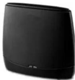
natural_image
Black rectangular electronic device with rounded edges and a small logo at the bottom (no visible text or symbols)All accessories and batteries are available from your phone retailer.

Use only original accessories. This will avoid possible health risks and personal injury, and also ensure that all the relevant regulations are complied with.
Compatibility
For more information on handset functions in relation to Gigaset bases, please visit: www.gigaset.com/compatibility
Mounting the base on the wall

A
Access code 86
for a PABX 86
Accessories 134
Activating
anonymous calling.... 41
call divert 42
network mailbox....64
ADSL....122
ALG 122
Alternative options....92
Annex B for G.729, enabling ..... 100
Anonymous calling....41
Answering machine
configuring for fast access ..... 64
Application Layer Gateway (ALG) ..... 122
Arabic characters, entering....92
Area code
setting own area code.... 78
Asymmetric Digital Subscriber Line .... 122
Authentication....122
Authorisation 120
Auto configuration....17
Auto configuration code.... 18
B
Base
connecting to PABX 86
power consumption....121
restoring to default settings. 84
setting 75
setting up 9,10
system PIN 77
updating firmware 82
Block dialling 122
Broadband connections 40
Broadband Internet access....122
Broadband voice codec....100, 126
Buttons 93
C
Call
accepting 37
ending....37
internal 71
transferring.... 46
transferring (connecting) ..... 46, 72
Call costs, see Making cost-effective calls
Call display
name from online directory.... 38
Call divert 42,122
Call duration.... 36
Call forwarding 122
Call swapping....45, 122
Call waiting....122, 123
accepting/rejecting 44
activating/deactivating.... 43
external call 43
internal call.... 73
Call, accepting 37
Caller picture 38
Calling
anonymously....41
entering IP address.... 36
from online directory.... 49
from Yellow Pages 49
internally.... 71
Calling Line Identification 38
Certificate error 17,54
CF 122
Changing
internal numbers 74
names of internal parties 73
system PIN 77
Checkboxes 92
CLI, CLIP 38
Client 123
CNIP 38
Codecs 123
COLP....37,123
COLR....37,123
Conference 46
Conference (internal) 72
Connected Line Identification
Presentation/Restriction ..... 37, 123
Connecting
base to PABX 86
to the Web configurator 88
Connection wizard
launching (getting started) 19
Consultation call 45,123
Consultation call (internal) 72
Consumption of electricity, see Power consumption (base)
Index
Cost control 53
Cost-effective calls, making 53
Costs, see Making cost-effective calls
Customer Care 111
CW....123
Cyrillic characters, entering .....92
D
Data packets, fragmentation ..... 125
Date, setting....34, 75
Deactivating anonymous calling.... 41 call divert .... 42 network mailbox.... 64
Demilitarised Zone 124
De-registering from Web configurator ..... 90
De-registering (handset) 70
DHCP 123,124
Dialling IP address 36
Differentiated Service Code Point.....124
Digital Subscriber Line....124 Access Multiplexer....124
Directory opening...... 47 searching for an entry...... 48 transferring to/from PC...... 107
Directory file content (vCard format) ..... 108
Directory transfer 107
Display call duration, costs .... 53 name (CNIP).... 38 name from online directory.... 38 number (CLI/CLIP).... 38
Display keys assigning.... 75
Display name (VoIP) 124
Disposal....119
DMZ 124
DNS....124
DNS server preferred.... 79
Domain name 124
Domain Name System 124
DSCP....124
DSL 124
DSLAM....124
DTMF signalling for VoIP....103
Dynamic DNS....125
Dynamic Host Configuration Protocol....123
Dynamic IP address 124
DynDNS....125
E
ECO DECT 67
Eco Mode 67
Eco Mode+ 67
ECT 46 activating/deactivating 43
E-mail deleting.... 58 messages whilst making a connection.... 56
notification.... 54
settings 106
viewing the sender's address...... 58
E-mail list.... 55
Ending a call....37
Entering Cyrillic/Arabic characters....92
Ethernet network 125
Explicit Call Transfer 125
External call call waiting.... 43
F
Fast access.... 64
Firewall....125
Firmware .... 125 checking version.... 118 starting update .... 82 updates.... 8
Fixed IP address....125
Flat rate 125
Fragmentation of data packets.....125
Full duplex 125
G
G.711 μ law.... 100
G.711 a law 100
G.722 40,100
G.722 broadband language codec.....100
G.726 100
G.729 100
Gateway....126
Gateway provider 126
Gigaset HDSP, see HDSP
Global IP address.... 126
Global System for Mobile Communication .... 126
Group call 71
GSM 126
H
Handset changing internal number ..... 74
changing name....73, 101
de-registering 69,70
locating....70
paging....70
registering 69
setting 75
transferring a call 72
HDSP....40,100
Headset 126
Help 111
High Definition Sound Performance, see HDSP
HTTP proxy 127
Hub....127
|
IEEE 127
Incoming e-mail list, opening 55
Incoming message list opening (e-mail) 55
Info Center ....59 operating ....61
Infrastructure network....127
Input fields 92
Installation wizard....16
Institute of Electrical and Electronics Engineers....127
Internal conference 72
consultation call 72
making calls 71
Internal call....71 call waiting....73
Internal names, changing ..... 73
Internal numbers, changing....74
Internet 127
Internet access (broadband) ..... 122
Internet protocol....127
Internet service provider....127
IP 127
IP address 127
assigning.... 78
dialling.... 36
dynamic....124
fixed....125
global....126
local 128
obtaining automatically 78
private....129
public....130
static....131
IP configuration....78
IP pool range 127
K
Key 1 (fast access) assigning....64
Key, assigning.... 75
L
LAN....128
List e-mail notifications.... 55 network mailboxes.... 66
Lists.... 92
Local Area Network....128
Local communication ports ..... 105
Local IP address 128
Local SIP port 131
Locating, handset 70
M
MAC address.... 128 checking.... 85
Making calls accepting a call .... 37 external.... 35 internal.... 71
Making cost-effective calls 53
Maximum Receive Unit 128
Maximum Transmission Unit ..... 128
Mbps 128
Media Access Control....128
Medical equipment 7
Menu Web configurator overview ..... 95
Menu bar.... 91
Message deleting (e-mail).... 58 playing back (network mailbox).... 66
Message key 54
Index
Message list
e-mail.....55
network mailboxes.... 66
Million bits per second....128
MRU 128
MTU 128
Music on hold....78, 128
MWI Light ....54, 106
N
Name
display name (VoIP) 124
displaying caller's name (CNIP) ..... 38
of a handset 73
of caller from online directory ..... 38
Name (handset), changing ..... 101
NAT 128
symmetric....132
Navigation area 91
Network....129
Ethernet....125
Network Address Translation.....128
Network mailbox....64
activating/deactivating....64
calling 65,66
configuring for fast access 64
entering number.... 64
list....66
Network MB, see Network mailbox
Notification
incoming e-mail 54
Number
displaying caller's number (CLIP) ..... 38
entering number of network mailbox. 64
Number display, withholding..... 41
Number key, assigning 75
0
Online directory.... 47
selecting 106
Operation (setting up the phone)....8
Options 92
Outbound proxy 129
P
PABX
connecting base 86
saving access code 86
PABX Gigaset T500/T300 PRO 16
Package contents ....8
Paging 70,129
PC address book entries
transferring to directory ..... 107
PC to Web configurator, connecting .... 87
Personal Identification Number ..... 129
Phone
setting 75
setting up....8
Phone number display, notes 39
Phone number display, withholding .... 41
Phone number, withholding 41
PIN....129
PIN, changing.... 77
PoE (Power over Ethernet) 10
Port 129
Port forwarding....129
Port number 129
Power adapter ....7
Power consumption (base)....121
Preferred DNS server 79
Prepare dialling 129
Private IP address 129
Protocol....130
Proxy....130
Proxy server 130
Public IP address 130
Q
Quality of Service 130
Questions and answers 111
Quick Start Wizard,Initial configuration.. 96
R
R key, function for VoIP 104
RAM 130
Random Access Memory....130
Read Only Memory....131
Receive number
display on the handset 38
Reception booster, see Repeater
Registering
with Web configurator.... 89
Registering (handset) 69
Registrar 130
Repeater 83
Restarting 109
RFC 2833 (DTMF signalling) ..... 103
Ringback
when the call is not answered.....130
when the number is busy....130
ROM 131
Router....131
Routing 131
RTP 131
RTP port....131
S
Saving (access code).... 86
Scope of delivery....8
Select services 41
Sender's address (e-mail) 58
Server....131
Service information, checking ..... 118
Services online directory....106
Setting online directory....106
Setting up, base....9, 10
Silence, suppressing....100
Simple Transversal of UDP over NAT . . . 132
SIP 131
SIP address 131
SIP port 131
SIP provider 131
SIP proxy server 131
Specifications....121
Speech pauses, suppressing.....100
Static IP address....131
Status codes (VoIP) codes table....115
Structure of IP address....127
Structure of Web pages.... 90
STUN....132
Subject (e-mail), reading ..... 57, 58
Subnet 132
Subnet mask....132 defining....79
Symmetric NAT 132
System PIN, changing 77
System settings securing....77
System settings, configuring .....75
T
TCP 132
Telephone care 111, 120
Three-party conference 46
Time, setting....34, 75
TLS....132
Transmission Control Protocol.....132
Transmission rate 132
Transport Layer Security 132
Transport protocol 132
Troubleshooting....111 e-mail....56 general....111
U
UDP....132
Uniform Resource Identifier ..... 133
Universal Resource Locator 133
URI....133
URL 133
User data (VoIP), entering with handset 23
User Datagram Protocol 132
User ID 133
Username 133
V
vCard format 108
vcf file....107
Voice over Internet Protocol.....133
VoIP....133 configuring account (first)....23 loading provider data....22 show called party's number....37 status codes (table)....115
VoIP account setting up via assistant ..... 96
VoIP provider .... 133 downloading data .... 22 selecting .... 22
VoIP status messages status codes table....115
VoIP user data entering (connection wizard) ..... 23
W
WAN 133
Weather forecast, in idle display mode .. 63
Web configurator connecting with PC .... 87 de-registering .... 90 DTMF signalling for VoIP.... 103 menu .... 95
Web page structure 90
Index
Wide Area Network.... 133
Withholding
phone number display .....41
suppressing speech pauses (VoIP) . . . 100
Working area 92
Y
Yellow Pages.... 47
Issued by
Gigaset Communications GmbH
© Gigaset Communications GmbH 2011
All rights reserved. Subject to availability.
Rights of modification reserved.
www.gigaset.com
A31008-M2217-R101-3-7619

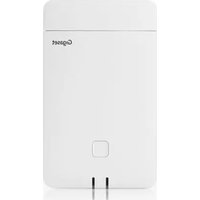
- Connect your Gigaset to the Internet and your PC via Ethernet.
- Upgrade your Gigaset to a cordless PABX
- It's easy to configure your Gigaset thanks to the wizards
- Go online with your Gigaset
- Other practical information
- Environment
- Functions of the button on the base
- Functions of the registration/paging button on the base
- Contents
- Using the network mailbox 64
- ECO DECT 67
- Connecting/using handsets 69
- Configuring the system settings 75
- Connecting the phone to a PABX 86
- Configuring the phone via the Web configurator 87
- Customer Service & Assistance 111
- Environment 119
- Warning
- Please note
- Checking the package contents
- Firmware updates
- Setting up the base
- First steps
- Connecting the base
- Connecting the power cable to the base
- Connecting the base to the mains power supply
- Connecting the base to a router (Internet)
- Data protection notice
- Connecting the PC to the router (optional)
- PC system requirements:
- Registering the handset
- a) On the handset
- b) On the base
- Setting up the phone – installation wizard
- Auto configuration:
- Launching the installation wizard
- IP wizard – making VoIP settings
- Either:
- Or:
- Launching the IP wizard
- No Internet connection:
- Entering the auto configuration code
- Downloading VoIP provider data
- You have not been able to download your provider's data
- Entering user data for your VoIP account
- Please note ...
- Connection wizard
- Default assignment
- Launching the connection wizard
- Assign connections to handset?
- Completing the installation
- Displays
- Date/time
- Proceeding
- Understanding the operating steps in the user manual
- Example:
- Messaging
- Voice Mail
- Select Services
- Info Centre
- Settings
- Contacts
- Making an external call
- Permanently assigned send connection
- Prerequisite:
- Selecting a line for each call
- Using an alternative connection/connection list on the display key
- Calling an IP address (provider-dependent)
- Displaying the phone number you are calling (COLP)
- Prerequisites:
- Ending a call
- Accepting a call
- Calling Line Identification
- Call display
- Adopting the name from the online directory
- Display with CNIP
- Notes on phone number display (CLIP)
- However, if the caller's number is not displayed, this can be due to the following:
- Is your telephone connected via a PABX/gateway?
- If the caller number is still not displayed:
- Have you requested the phone number display service from your network provider?
- Gigaset HDSP – telephony with brilliant sound quality
- Please note:
- Configuring general settings for all calls
- Anonymous calling – withholding phone number
- Activating/deactivating "anonymous calling" for all calls
- All Calls anon.
- General call divert (CD)
- Diverting calls to an external connection (VoIP)
- → Select Services → Call Divert
- Status
- To Phone Number
- When
- Diverting calls internally
- Activation
- To Handset
- Ring Delay
- Activating/deactivating call waiting for external calls
- Activating/deactivating call waiting
- Activating/deactivating call transfer – ECT (Explicit Call Transfer)
- Activating "anonymous calling" for the next call
- Configuring settings during an external call
- Accepting a waiting call
- Rejecting a waiting call
- Consultation calls (external)
- Ending a consultation call
- Call swapping
- Ending a currently active call
- Conference
- Ending a conference call
- Transferring calls
- Transferring a call to an internal party
- Using online directories
- Exclusion of liability
- Opening an online directory/Yellow Pages
- Searching for an entry
- Search result (hit list)
- Refine Search
- New Search
- Copy to Directory
- Copy to Private NetDir.
- Calling subscribers
- Starting a refined search
- Using the private net directory
- Opening the online directory
- Selecting, viewing and managing entries in the online directory
- Using other functions
- Edit nickname
- Calling up an entry in the online directory
- Transferring the local directory to the private online directory
- Defining dialling plans
- Displaying the call duration
- Opening the incoming e-mail list
- Messages when establishing a connection
- Server not accessible
- Currently not possible
- Logon at mail server failed
- Mailbox parameters incomplete
- Viewing the message header and text of an e-mail
- Viewing e-mail sender's address
- Deleting e-mail messages
- Info Center – continuous Internet access from your phone
- Configuring your own applications/info services
- Starting the Info Center, selecting info services
- Messages when loading requested information
- Requested page cannot be reached
- Coding error on requested page
- Unable to show requested page
- Authorization Failed
- Logging in for personalised info services
- Authent. Name
- Authent. Password
- Operating the Info Center
- Scrolling within an info service
- Skipping back to the previous page
- Skipping back to the Info Center menu
- Selecting a hyperlink
- Hyperlink to further information:
- Hyperlink to a phone number:
- Entering text
- Making selections
- Setting options
- Displaying information from the Internet as a screensaver
- Selecting information for the screensaver
- Activating/deactivating network mailboxes, entering numbers
- Network Mailbox
- Configuring a network mailbox for fast access
- Assigning key 1, changing assignment
- Calling the answering machine via fast access
- Displaying new messages in the handset's idle display
- Calling the network mailbox using the message key
- Mailbox IP 1: / Mailbox IP 2: / ... / Mailbox IP 6:
- Reducing energy consumption
- Reducing radiation
- Eco Mode
- Switching off radiation
- ◆Eco Mode+
- Registering handsets
- 1) On the handset
- On the Gigaset SL610 PRO handset, for example:
- 2) On the base
- Assigning the internal number
- De-registering handsets
- Locating a handset, finding the phone's IP address ("paging")
- Ending paging
- Making internal calls
- Calling a specific handset
- Calling all handsets ("group call")
- Transferring a call to another handset
- Initiating an internal consultation call/conference
- External call waiting during an internal call
- Rejecting the external call
- Accepting an external call/putting an internal party on hold
- Ending an internal call
- Internal call waiting during an internal/external call
- Changing the name of an internal party
- Changing the internal number of an internal party
- Setting the date/time
- Setting the date and time on the handset
- Date:
- Time:
- Quickly accessing functions
- Configuring the system settings
- Withhold Number
- More Functions...
- Send Connection
- Connect. Selection
- Call Lists
- Call Divert
- Starting a function
- Protecting the telephone from unauthorised access
- Changing the system PIN
- Setting your own area code
- Activating/deactivating music on hold
- Setting the base's IP address in the LAN
- IP Address Type
- For IP Address Type Static:
- IP Address
- Subnet Mask
- DNS Server
- Default Gateway
- Configuring VoIP connections
- Automatic update for the VoIP provider settings
- Auto configuration has been used to download VoIP settings (→ page 17)
- Manual VoIP configuration with the VoIP wizard
- Assigning send and receive connections to internal parties
- Assigning a send connection
- Assigning receive connection(s)
- Updating the phone firmware
- Starting the firmware update manually
- Repeater support
- Restarting the base
- Resetting the base to the default settings
- Resetting the base via the menu
- Resetting the base using the button on the base
- Checking the base MAC address
- Connecting the phone to a PABX
- Saving an access code (outside line code)
- Access external IP line with:
- For:
- Configuring the phone via the Web configurator
- Connecting the PC with the telephone's Web configurator
- Establishing a connection via the phone's IP address
- Logging into/off the Web configurator
- Logging in, setting the interface language
- Logging off
- Understanding the structure of the Web configurator pages
- Menu bar
- Home
- Log Off
- Navigation area
- Working area
- Making changes
- Entering Cyrillic and Turkish characters
- Applying changes
- Buttons
- Cancel
- Set
- Help
- Means of representation in Help
- Bold font
- [Bold font]
- Telephony > Dialling Plans
- Searching in Help
- Opening Web pages
- Example
- Functions of the Web configurator
- Quick Start Wizard
- Connecting the base to the local network (LAN/router)
- Settings → Network → IP Configuration
- Making security settings – managing certificates for TLS authentication
- Settings → Network → Security
- Managing base connections – activating/deactivating connections
- IP Connections
- Configuring/deleting VoIP connections
- Optimising voice quality for VoIP connections
- G.722
- G.711 a law / G.711 μ law
- G.726
- G.729
- Assigning send and receive connections
- Settings → Telephony → Number Assignment
- Changing the name of the handsets
- Activating call divert
- Settings → Telephony → Call Divert
- User-defined dialling plans – specifying rules for telephony
- Settings → Telephony → Dialling Plans
- Tip:
- Examples
- Access codes – activating dialling plans when connecting to a PABX
- Activating local area codes for calls using VoIP
- Entering the network mailbox, enabling/disabling the network mailbox
- Setting DTMF signalling for VoIP
- Configuring call transfer via VoIP
- Settings → Telephony → Advanced VoIP Settings
- Defining R key functions for VoIP (hook flash)
- Defining local communication ports (listen ports) for VoIP
- Making settings for access to Internet services
- ◆E-mail notifications
- ◆MWI Light
- ◆Online directories
- ◆Managing the synchronisation of the base with a time server
- Deleting handset directories and downloading to/from the PC
- Transfer rules
- Directory file content (vcf file)
- Example of an entry in vCard format:
- Changing the base settings, registering handsets
- Restarting the device or restoring the factory settings
- Saving and restoring system settings
- Updating firmware for the base/downgrading firmware updates
- Settings → Management → Firmware Update
- Displaying the phone status
- Status → Device
- Status → Connections
- Questions and answers
- Information on operating Gigaset VoIP telephones with routers with Network Address Translation (NAT)
- Typical problems caused by NAT
- Possible solution
- Changing the port numbers for SIP and RTP on your VoIP phone
- To change the SIP and RTP port numbers on your VoIP phone, proceed as follows:
- Setting port forwarding on the router
- To define port forwarding on the router, proceed as follows:
- Protocol
- Public port
- Local port
- Local host (IP)
- VoIP status codes
- Checking service information
- Options → Service Info
- Unlock system
- Update profile
- Send configurat.
- Our environmental mission statement
- Environmental management system
- Disposal
- Caring for your telephone
- Contact with liquid ⚠️!
- Authorisation
- Specifications
- Base power consumption
- A
- ADSL
- ALG
- Authentication
- Automatic ringback
- B
- Block dialling
- Broadband Internet access
- C
- Call waiting
- CF
- Client
- Codec
- COLP/COLR
- Consultation call
- CW
- D
- DHCP
- Display name
- DMZ (Demilitarised Zone)
- DNS
- Domain name
- DSCP
- DSL
- DSLAM
- DTMF
- Dynamic IP address
- DynDNS
- E
- ECT
- EEPROM
- Ethernet network
- F
- Firewall
- Firmware
- Fixed IP address
- Flat rate
- Fragmentation
- Full duplex
- G
- G.711 a law, G.711 μ law
- G.729A/B
- Gateway
- Gateway provider
- Global IP address
- GSM
- H
- Headset
- HTTP proxy
- Hub
- IEEE
- Infrastructure network
- Internet
- Internet service provider
- IP (Internet Protocol)
- IP pool range
- L
- LAN
- Local IP address
- Local SIP port
- M
- MAC address
- Mbps
- MRU
- MTU
- Music on hold
- N
- NAT
- Network
- Network subscriber
- 0
- Outbound proxy
- P
- Paging (handset search)
- PIN
- Port
- Port forwarding
- Port number
- Prepare dialling
- Private IP address
- Proxy/Proxy server
- Public IP address
- Q
- Quality of Service (QoS)
- R
- RAM
- Registrar
- Ringback when the call is not answered
- Ringback when the number is busy
- ROM
- Router
- Routing
- RTP
- RTP port
- S
- Server
- SIP (Session Initiation Protocol)
- SIP address
- SIP port/Local SIP port
- SIP provider
- SIP proxy server
- Static IP address
- STUN
- Subnet
- Symmetric NAT
- T
- TCP
- TLS
- Transmission rate
- Transport protocol
- U
- UDP
- URI
- URL
- User ID
- Username
- V
- Voice codec
- VoIP
- VoIP provider
- W
- WAN
- Gigaset handsets
- Gigaset SL610H PRO handset
- Gigaset SL400 handset
- Gigaset S79H/S810H handset
- Accessories
- Gigaset SL78H handset
- Gigaset handset
- Gigaset E49H handset
- Gigaset repeater
- Compatibility
- Mounting the base on the wall
- Index
- |
- K
- Issued by
Brand : GIGASET
Model : N510 IP PR
Category : Telephone