
FCS-3071 - Surveillance Camera LEVELONE - Free user manual and instructions
Find the device manual for free FCS-3071 LEVELONE in PDF.


| Product Type | Surveillance Camera |
| Brand | LevelOne |
| Model | FCS-3071 |
| Image Sensor | 1/3" Progressive Scan CMOS |
| Resolution | 1920 x 1080 (Full HD) |
| Lens | Fixed focal length, 2.8mm |
| Night Vision | IR LEDs, up to 30m |
| Audio | Two-way audio via built-in microphone and speaker |
| Network | Ethernet 10/100 Base-T, Wi-Fi 802.11n |
| Power | 12V DC / PoE (802.3af) |
| Dimensions | 7.2 x 7.2 x 12.5 cm |
| Weight | 350 g |
| Storage | MicroSD card slot (up to 128GB), Cloud storage |
| Weatherproof | IP66 |
| Motion Detection | Yes, with email and push alerts |
| Alarm I/O | 1 input / 1 output |
| Video Compression | H.265, H.264 |
| Supported Protocols | IPv4, IPv6, TCP, UDP, HTTP, RTSP, ONVIF |
| Mounting | Wall mount included |
| Operating Temperature | -20°C to 50°C |
| Operating Humidity | 10% to 90% non-condensing |
| Maintenance | Clean lens with soft cloth; check cables and connections |
| Safety | Use surge protector; ensure proper grounding |
| Spare Parts & Repairability | Power adapter, mounting kit; repair by authorized service |
| General Information | Manufacturer: LevelOne; Warranty: 2 years |
Frequently Asked Questions - FCS-3071 LEVELONE
User questions about FCS-3071 LEVELONE
0 question about this device. Answer the ones you know or ask your own.
Ask a new question about this device
Download the instructions for your Surveillance Camera in PDF format for free! Find your manual FCS-3071 - LEVELONE and take your electronic device back in hand. On this page are published all the documents necessary for the use of your device. FCS-3071 by LEVELONE.
USER MANUAL FCS-3071 LEVELONE
2-Megapixel PoE Dome Network Camera

User Manual
Ver1.4
Table of Contents
1. Introduction......3
1.1 Features .... 3
1.2 Package Contents 4
1.3 Camera Overview....4
2. Preparations for IP Camera Setup ....6
2.1 System Requirements 6
3. Accessing Camera 6
Using recording software.... 11
Installing DC Viewer Software Online....12
4. Configuration & Operation....15
4.1 Browser-based Viewer Introduction .....15
4.2 Home Page....17
4.3 System Related Settings....19
4.3.1 Host Name and System Time Setting....20
4.3.2 Security....21
4.3.3 Network....24
4.3.4 DDNS....29
4.3.5 Mail 30
4.3.6 FTP....31
4.3.7 Motion Detection 32
4.3.8 Storage Management....36
4.3.9 Recording.... 38
4.3.10 File Location.... 39
4.3.11 View Log File....40
4.3.12 View User Information....41
4.3.13 View Parameters.... 43
4.3.14 Factory Default.... 44
4.3.15 Software Version.... 45
4.3.16 Software Upgrade 46
4.3.17 Maintenance....49
4.4 Video Streaming Settings ....50
4.4.1 Video Resolution and Rotate Type....50
4.4.2 Video Compression....53
4.4.3 Video OCX Protocol....55
4.4.4 Video Frame Skip....56
4.4.5 Video Mask 57
4.5 Camera Settings....58
4.5.1 Exposure Setting.... 58
4.5.2 White Balance Setting....60
4.5.3 Brightness Setting.... 61
4.5.4 Sharpness Setting....61
4.5.5 Contrast Setting 61
4.5.6 Saturation Setting....61
4.5.7 Hue Setting .... 62
4.5.8 TV System Setup 62
4.6 Logout 63
Appendix A: Technical Specifications....64
Appendix B: Internet Security Settings 66
Appendix C: DC Viewer Download Procedure 69
Appendix D: Install UPnP Components....71
Default ID / Password
Login ID Password
root null(without password)
1. Introduction
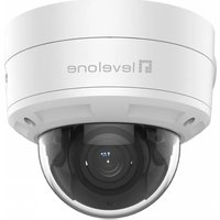
The LevelOne FCS-3071 is a compact, rugged H.264 2-Megapixel PoE Mini Dome Camera designed for tough environments. The casing is tamper-resistant, it can withstand vibration, humidity, dust and fluctuating temperatures found. for example buses and trains.
The FCS-3071 is a palm-sized, discreet network camera specifically designed for mass transit vehicles. The flat tamper-resistant casing makes it ideal for installation. The IP66 rating provides a rugged package for both indoor and outdoor applications
In compatible with EN50155, the standard for electronic equipment operating in railway vehicles, the FCS-3071 is an economical mobile surveillance solution with high reliability and rugged performance.
The FCS-3071 utilizes PoE (Power-over-Ethernet), allowing it to be operated and powered from a single Ethernet cable, giving greater ease of installation and cost savings. In order to facilitate on-board storage and data portability, the FCS-3071 is also complete with a Micro SD/SDHC card slot for local recording.
1.1 Features
- 2-Megapixel Progressive Scan CMOS Sensor
- Dual streaming simultaneously
- H.264 and MJPEG Compression
- Shockproof for Rolling Stock Applications
- Weatherproof IP66 housing & RJ-45 dongle cable
- Micro SD/SDHC Card Slot for On-Board Storage
- Powered by PoE (802.3af) Only
- Free software included (Industry-leading 64-channel IP CamSecure™ software)
1.2 Package Contents
Please check the package contains the following items listed below.
 Indoor Camera/Rugged Camera (with Cable) Indoor Camera/Rugged Camera (with Cable) |  Self-tapping screws (×3) Self-tapping screws (×3) |  Plastic Anchors (×3) Plastic Anchors (×3) |  Security Screw (×1) Security Screw (×1) |
 Rubber Washer (×1, Casing)Rubber Washers (×3, Baseplate)(Rugged Camera only) Rubber Washer (×1, Casing)Rubber Washers (×3, Baseplate)(Rugged Camera only) |  Security Torx Security Torx |  Quick Guide Quick Guide |  CD CD |
1.3 Camera Overview


Designation Description
| 1 | Reset Button | Restore to default setting; press the button with a proper tool |
| 2 | Lens Rotate the lens | right/left to adjust focus |
| 3 | Focus Fixed Screw | Loosen the screw to adjust the lens |
| 4 | Tilt Fixed Screw Loo | sen the screw to adjust tilt angle |
| 5 | Micro SD Card Slot | Micro SD Card recording |
Dimensions

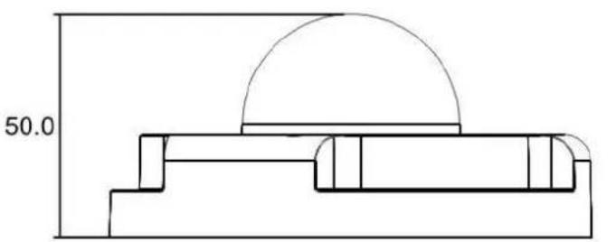
Unit: (mm)
2. Preparations for IP Camera Setup
This chapter provides information about system requirements for IP Dome Camera operation, power and Ethernet connection for Indoor/Outdoor IP Dome Camera and ways to access to the camera.
2.1 System Requirements
To perform the IP Camera via web browser, please ensure your PC is in good network connection, and meet system requirements as described below.
| Items System Requirement | |
| Personal Computer | 1. Intel® Pentium® M, 2.16 GHz or Intel® CoreTM2 Duo, 2.0 GHz2. 2 GB RAM or more |
| Operating System | Windows VISTA or Windows XP |
| Web Browser | Microsoft Internet Explorer 6.0 or later |
| Network Card | 10Base-T (10 Mbps) or 100Base-TX (100 Mbps) operation |
| Viewer | ActiveX control plug-in for Microsoft IE |
3. Accessing Camera
For initial access to the IP Camera, users can search the camera through the installer program: DeviceSearch.exe, which can be found in "Device Search" folder in the supplied CD.
Device Search Software Setup
Step 1: Double click on the program Device Search.exe (see the icon below); its window will appear as shown below. Then click the "Device Search" button.


Step 2: The security alert window will pop up. Click "Unblock" to continue.

Device Search
Step 3: Click "Device Search" again, and all the finding IP devices will be listed in the page, as shown in the figure below. The IP Camera's default IP address is: 192.168.0.250.

Step 4: Double click or right click and select "Browse" to access the camera directly via web browser.
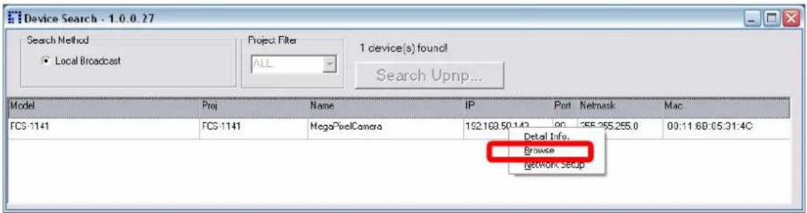
Step 5: Then the prompt window of request for entering default username and password (as shown below) will appear for logging in to the IP Dome Camera.
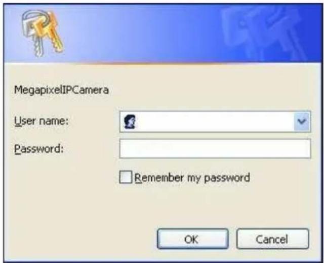
The default login ID and password are:
| Login ID Password |
| root null(without password) |

NOTE: ID and password are case sensitive.

NOTE: It is strongly advised that administrator's password be altered for the security concerns. Refer to section 5.3.2 Security or further details.
Additionally, users can change the IP Camera's network property, either DHCP or Static IP, directly in the device finding list. Refer to the following section for changing the IP Camera's network property.
Example of Changing IP Camera's Network Property
Users can directly change an IP Camera's network property, ex. from static IP to DHCP, in the finding device list. The way to change the IP Camera's network property is specified below:
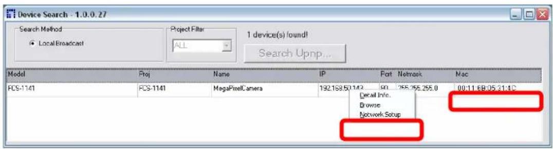
Step 1: In the finding device list, click on the IP Camera that you would like to change its network property. On the selected item, right click and select "Network Setup." Meanwhile, record the IP Camera's MAC address, for future identification.
Step 2: The “Network Setup” page will come out. Select “DHCP,” and press “Apply” button down the page.
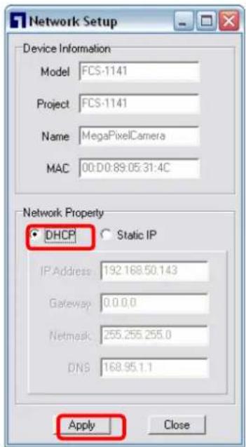
Step 3: Click "OK" on the Note of setting change. Wait for one minute to re-search the IP Camera.

Step 4: Click the "Device Search" button to search all the devices. Then select the IP Camera with the correct MAC address. Double click on the IP Camera, and the login window will come out.

Step 5: Enter User name and Password to access the IP Camera.
Using recording software
The product software CD also contains recording software-IP CamSecure, allowing simultaneous monitoring and video recording for multiple Network Cameras. Please install the recording software; then launch the program to add the Network Camera to the Channel list. For detailed information about how to use IP CamSecure, please refer to the user's manual of the software or download it at http://global.level1.com.

Installing DC Viewer Software Online
For the initial access to the IP Camera, a client program, DC Viewer, will be automatically installed to your PC when connecting to the IP Camera.
If the Web browser doesn't allow DC Viewer installation, please check the Internet security settings or ActiveX controls and plug-ins settings (see Appendix B: Internet Security Settings) to continue the process.
The Information Bar (just below the URL bar) may come out and ask for permission to install the ActiveX Control for displaying video in browser (see the figure below). Right click on the Information Bar and select "Install ActiveX Control..." to allow the installation.

Then the security warning window will pop up. Click "Install" to carry on software installation.

Click "Finish" to close the DC Viewer window when download is finished. For the detailed software download procedure, please refer to Appendix C: DC Viewer Download Procedure.
Once login to the IP Camera, users will see the Home page as shown below:
![levelone Home System Streaming Camera Logout 2007/01/01 00:46 Video format ○ MJPEG ○ H.264 x 1 x 1/2 Full [ ] [ ] [ ] MJPEG bitrate : middle compression , middle quality H.264 bitrate : 4096kbps,middle compression](/content/2026/06/1283676/images/6b0f2e4f404489c4d457ce84fee7a01756fe2d67f36629e0284e84c488b02838.jpg)
Administrator/User Privileges
"Administrator" represents the person who can configure the IP Camera and authorize user's access to the camera; "User" refers to whoever has access to the camera with limited authority, i.e. entering Home and Camera setting pages.
Image and Focus Adjustment
The image displays on the Home page when successfully accessing to the IP Camera. Adjust zoom and focus as necessary to produce a clear image.
Step 1: Unscrew the IP Dome Camera's cover.

Step 2: Loosen the focus fixed screw, and rotate the lens counter-/clockwise to adjust focus; loosen the tilt fixed screw, and adjust the camera's tilt angle.

4. Configuration & Operation
The IP Camera is provided with a user-friendly browser-based configuration interface, as well as a free bundled CMS (Central Management System) for video playback and recording. In this chapter, information about main page introduction, system related settings and camera settings will be described in detail.
For further information about CMS software, please refer to IP CamSecure user manual.
4.1 Browser-based Viewer Introduction
The figure below shows the Home page of the IP Camera's Viewer Window.


NOTE: Please note that the function buttons will vary depending on the camera model.
There are five tabs: Home, System, Streaming, Camera and Logout on the top of the viewer window.
Home
Users can monitor live video of the targeted area.
System setting
The administrator can set host name, system time, root password, network related settings, etc. Further details will be interpreted in section "System Related Settings".
Streaming setting
The administrator can modify video resolution and rotate type in this page.
Camera setting
Users can adjust various camera parameters, including
Logout
Click on the tab to re-login the IP Camera with another username and password.
4.2 Home Page
In the Home page, there are several function buttons right down the displayed image.


NOTE: Please note that the function buttons will vary depending on the camera model.
Screen Size Adjustment
Image display size can be adjusted to x1/2 and full screen.
Digital Zoom Control
In the full screen mode, users can implement digital PTZ by rotating the mouse wheel (for zoom in/out), and drag the mouse into any direction.
Snapshot button

Press the button, and the JPEG snapshots will automatically be saved in the appointed place. The default place of saving snapshots is: C:. To change the storage location, please refer to section "File Location" for further details.
Video Streaming Pause /Restart button


(pause/restart)
Press the stop button to disable video streaming, the live video will be displayed as black. Press the restart button to show the live video again.
Recording button


(on/off)
Press the button and the recordings from the Live View will be saved to the location specified in the "File Location" (snapshot) page; see section "File Location" for further details.
4.3 System Related Settings
The figure below shows all categories under the "System" tab. Each category in the left column will be explained in the following sections.

NOTE: The "System" configuration page is only accessible by the Administrator.

4.3.1 Host Name and System Time Setting
Press the first category:

Host Name
The name is for camera identification. If alarm function is enabled and is set to send alarm message by Mail/FTP, the host name entered here will display in the alarm message.
Time Zone
Select the time zone you are in from the drop-down menu.
Enable Daylight Saving Time
To enable DST, please check the item and then specify time offset and DST duration. The format for time offset is [hh:mm:ss]; for instance, if the amount of time offset is one hour, please enter "01:00:00" into the field.
Sync With Computer Time
Select the item, and video date and time display will synchronize with the PC's.
Manual
The Administrator can set video date, time and day manually. Entry format should be identical with that shown next to the enter fields.
Sync with NTP server
Network Time Protocol (NTP) is an alternate way to synchronize your camera's clock with a NTP server. Please specify the server you wish to synchronize in the enter field. Then select an update interval from the drop-down menu. For further information about NTP, please see the web site: www.ntp.org.
4.3.2 Security
Click the category:

Root password
Change the administrator's password by inputting the new password in both text boxes. The input characters/numbers will be displayed as dots for security purposes. After clicking

NOTE: The following characters are valid: A-Z, a-z, 0-9, !#\$%&'-.@^_^\~.
Add user
Type the new user's name and password and click
- I/O access
This item supports fundamental functions that enable users to view video when accessing to the camera.
- Camera control
This item allows the appointed User to change camera parameters on the Camera Setting page.
- Talk/Listen
Talk and Listen functions allow the appointed user in the local site (PC site) communicating with, for instance, the administrator in the remote site.

NOTE: The Compact IP Dome Camera does not have the Talk function.
Manage User
Delete user
To delete a user, pull down the user list, and select the user name you wish to delete. Then click
Edit user
Pull down the user list and select a user name. Click

NOTE: It is required to enter the User password as well as select the function open to the user. When finished, click
![http://192.168.7.123/lang1/server_editaccount..... http://192.168.7.123/lang1/server_editaccount.html User name [user] User password ✓ I/O access □ Talk Save Camera control □ Listen Close Don Internet 100%](/content/2026/06/1283676/images/bea401930dbc41c00ade798f4ceff5782b0b0769f28e304e5e0898c03a456be6.jpg)
![http://192.168.7.123/lang1/server_editaccount..... http://192.168.7.123/lang1/server_editaccount.html User name [user] User password ••••• ✓ I/O access ✓ Camera control ✓ Talk ✓ Listen Save Close Don Internet 100%](/content/2026/06/1283676/images/0f54dd8fba17db721dac209c7a688e1063d7383419952730b71627840c32cda8.jpg)
4.3.3 Network
Click

Users can choose to connect to the IP Camera with fixed or dynamic (DHCP) IP address. The IP Camera also provides PPPoE support for users who connect to the network via PPP over Ethernet (PPPoE).
Get IP address automatically (DHCP)
The camera's default setting is "Use fixed IP address". Please refer to the previous section "Accessing Camera" for logging in with the default IP address.
If select "Get IP address automatically", after the IP Camera restarts, users can search it through the installer program: Device Search.exe, which can be found in "Device Search" folder in the supplied CD.

NOTE: Please make the record of the IP Camera's MAC address, which can be found in the label of the camera, for identification in the future.
Use fixed IP address
To setup static IP address, select "Use fixed IP address" and move the cursor to the IP address blank (as indicated below) and insert the new IP address, ex. 192.168.7.123; then go to the Default gateway (explained latter) blank and change the setting, ex. 192.168.7.254. Press "Save" to confirm the new setting.

When using static IP address to login to the IP Camera, users can access it either through "Device Search" software (see :Accessing Camera") or input the IP address in the URL bar and press "Enter".

- IP address
This is necessary for network identification.
- Subnet mask
It is used to determine if the destination is in the same subnet. The default value is "255.255.255.0"
- Default gateway
This is the gateway used to forward frames to destinations in different subnet. Invalid gateway setting will fail the transmission to destinations in different subnet.
- Primary DNS
Primary DNS is the primary domain name server that translates hostnames into IP addresses.
- Secondary DNS
Secondary DNS is a secondary domain name server that backups the primary DNS.
Use PPPoE
For the PPPoE users, enter the PPPoE Username and Password into the fields, and click on the "Save" button to complete the setting.
Advanced
- Web Server port
The default web server port is 80. Once the port is changed, the user must be notified the change for the connection to be successful. For instance, when the Administrator changes the HTTP port of the IP Camera whose IP address is 192.168.0.100 from 80 to 8080, the user must type in the web browser “http://192.168.0.100:8080” instead of http://192.168.0.100.
- RTSP port
RTSP port could be set from 1 to 65535. (Normal Setting Port: 554, 1024 \~65535)
- MJPEG over HTTP port
The default setting of HTTP Port is 8008; setting range: 1024 \~65535.

NOTE: Be aware to choose the different port from the one set for the web server port.
UPnP Setting
- Enable UPnP
When the UPnP is enable, whenever the IP Camera is presented to the LAN, the icon of the connected IP Cameras will appear in My Network Places to allow for direct access as shown below.


NOTE: To enable this function, please make sure the UPnP component is installed on your computer. Please refer to Appendix D: Install UPnP components for UPnP component installation procedure.
- Enable UPnP port forwarding
When the UPnP port forwarding is enabled, the IP Camera is allowed to open the web server port on the router automatically.

NOTE: To enable this function, please make sure that your router supports UPnP and it is activated
- Friendly name
Set the name for the IP Camera for identity.
4.3.4 DDNS
Dynamic Domain Name System (DDNS) allows a host name to be constantly synchronized with a dynamic IP address. In other words, it allows those using a dynamic IP address to be associated to a static domain name so others can connect to it by name.

Enable DDNS
Check the item to enable DDNS.
Provider
Select one DDNS host from the provider list.
Host name
Enter the registered domain name in the field.
Username/E-mail
Enter the username or e-mail required by the DDNS provider for authentication.
Password/Key
Enter the password or key required by the DDNS provider for authentication.
4.3.5 Mail
The Administrator can send an e-mail via Simple Mail Transfer Protocol (SMTP) when motion is detected. SMTP is a protocol for sending e-mail messages between servers. SMTP is a relatively simple, text-based protocol, where one or more recipients of a message are specified and the message text is transferred. The configuration page is shown as follows:

Two sets of SMTP can be configured. Each set includes SMTP Server, Account Name, Password and E-mail Address settings. For SMTP server, contact your network service provider for more specific information.
4.3.6 FTP
The Administrator can set as sending alarm message to a specific File Transfer Protocol (FTP) site when motion is detected. Users can assign alarm message to up to two FTP sites. The FTP setting page is shown below. Enter the FTP details, which include server, server port, user name, password and remote folder, in the fields. Press "Save" when finished.

4.3.7 Motion Detection
Motion Detection function allows detecting suspicious motion and triggering alarms when motion volume in the detected area reaches/exceeds the determined sensitivity threshold value.
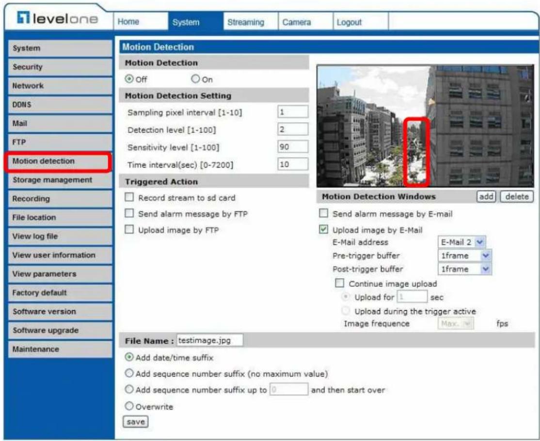
In the Motion Detection setting page, there is a frame (Motion Detection Window) displayed on the Live View Pane. The Motion Detection Window is for defining the motion detection area. To change the size of the Motion Detection Window, move the mouse cursor to the edge of the frame and draw it outward/inward. Moving the mouse to the center of the frame can shift the frame to the intended location.
Up 10 Motion Detection Windows can be set. Press the "add" button under the Live View Pane to add a Motion Detection Window. To cancel a Motion Detection Window, move the mouse cursor to the selected Window, and click on the "delete" button.
If Motion Detection function is activated, the pop-off window (Motion) with indication of motion will be shown.
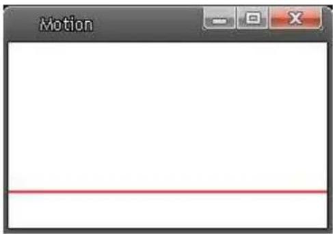
When motion is detected, the signals will be displayed on the Motion window as shown below.

Detailed settings of Motion Detection are described as follows:
Motion Detection
You will be able to turn on/off Motion Detection in System section. Default setting is Off.
Motion Detection Setting
Users could adjust various parameters of Motion Detection in this section.
- Sampling pixel interval [1-100]: The default value is 10, which means system will take one sampling pixel for every 10 pixel.
- Detection level [1-100]: The default level is 10. The item is to set detection level for each sampling pixel; the smaller the value, the more sensitive it is.
- Sensitivity level [1-100]:
The default level is 80, which means if 20% or more sampling pixels are detected differently, system will detect motion. The bigger the value, the more sensitive it is. Meanwhile, when the value is bigger, the red horizontal line in the motion indication window will be lower accordingly.
• Time interval (sec) [0-7200]:
The default interval is 10. The value is the interval between each detected motion.
Triggered Action (Multi-option)
The Administrator can specify alarm actions that will take when motion is detected. All options are listed as follows:
- Enable Alarm Output
Check the item and select the predefined type of alarm output to enable alarm relay output when motion is detected.

NOTE: This option is excluded in the Compact IP Dome Camera.
- Record stream to SD Card
Select this item, and the Motion Detection recording will be stored in Micro SD/ SDHC card when motion is detected.

NOTE: Please make sure the local recording (with Micro SD/SDHC card) is activated so that this function can be implemp-lemented. See section "Recording" for further details.
- Send Alarm Message by FTP/E-Mail
The Administrator can select whether to send an alarm message by FTP and/or E-Mail when motion is detected.
- Upload Image by FTP
Select this item, and the Administrator can assign a FTP site and configure various parameters as shown in the figure below. When motion is detected, event images will be uploaded to the appointed FTP site.

- Upload Image by E-Mail
Select this item, and the Administrator can assign an e-mail address and configure various parameters as shown in the figure below. When motion is detected, event images will be sent to the appointed e-mail address.
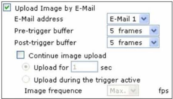

NOTE: Make sure SMTP or FTP configuration has been completed. See section "Mail" and "FTP" for further details.
File Name
The uploaded image's filename format can be set in this section. Please select the one that meets your requirements.
Save
Click the Save button to save all the Motion Detection settings mentioned above.
4.3.8 Storage Management
Users can implement local recording to the Micro SD/SDHC card.

NOTE: Please format the Micro SD/SDHC card first before recording starts.

Device information
When users insert the Micro SD/SDHC card, the card information such as the memory capacity and status will be shown at Device Information section.
Device setting
Press the "Format" button to format the memory card.
Disk cleanup setting
Users can enable automatic recordings cleanup by specifying the time and storage limits
Recording List
Each video file on the Micro SD/SDHC card will be listed in the Recording list as shown below.

- Remove
To remove a file, select the file first, and then press the "Remove" button.
- Sort:
Press the "Sort" button, and the files in the Recording list will be listed in name and date order.

NOTE: The capital letter A/M/R appears in the very beginning of name denotes the sort of the recording: A stands for Alarm; M stands for Motion; R stands for regular recording.
- Download:
To open/download a video clip, select the file first, and then press the "download" button below the Recording list field. The selected file window will pop up as shown below. Click on the AVI file to directly play the video in the player or download it to a specified location.

4.3.9 Recording
In the Recording setting page, users can specify the recording schedule that fits the present surveillance requirement.

Activating Micro SD/SDHC Card Recording
Two types of schedule mode are offered: Always and Time Frame setting. Users can setup the time frame to fit the recording schedule or choose "Always" to activate Micro SD/SDHC Card Recording all the time.
Please click on the "Save" button for confirming the schedule mode.
Terminating Micro SD/SDHC Card Recording
Select "Disable" to terminate the recording function.
4.3.10 File Location
Users can specify a storage location for the snapshots and live video recording. The default setting is: C:. Once confirm the setting, press "Save," and all the snapshots and recording will be saved in the designate location.

NOTE: Please make sure the selected file path contains valid characters such as letters and numbers.

4.3.11 View Log File
Click on the link to view the system log file. The content of the file provides useful information about configuration and connections after system boot-up.
![levelone Home System Streaming Camera Logout System Security Network DDNS Mail FTP Motion detection Storage management Recording File location View log file View user information View parameters Factory default Software version Software upgrade Maintenance System log [Fri Oct 29 10:37:00 2010] --Net…](/content/2026/06/1283676/images/de9974fde8039bb372deefa487b43aa3c2dee1eb7324edf5fadf97261c739d30.jpg)
4.3.12 View User Information
The Administrator can view each added user's login information and privileges (see "Security").
View User Login Information
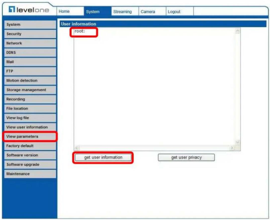
All the users in the network will be listed in the "User information" zone, as shown below. As the figure below shows:
User: root
It indicates that one user's login username is: root, and the password is: blank.
View User Privilege
Press “get user privacy” down the page, and the Administrator can view each user’s privileges.

As the figure above shows:
User: 1:1:0:1
1:1:0:1= I/O access : Camera control : Talk : Listen (see "Security")

Therefore, it denotes the user is granted privileges of I/O access, Camera control and Listen.
4.3.13 View Parameters
Click on this item to view the entire system's parameter setting.

4.3.14 Factory Default
The factory default setting page is shown as below. Follow the instructions to reset the IP Camera to factory default setting if needed.

Set Default
Click on the "Set Default" button to recall the factory default settings. Then the system will restart in 30 seconds.

NOTE: The IP address will be restored to default.
Reboot
Click on the "Reboot" button, and the system will restart without changing current settings.
4.3.15 Software Version
The current software version is displayed in the software version page, which is shown as the figure below.

4.3.16 Software Upgrade
Software upgrade can be carried out in the "Software Upgrade" page, as shown below.
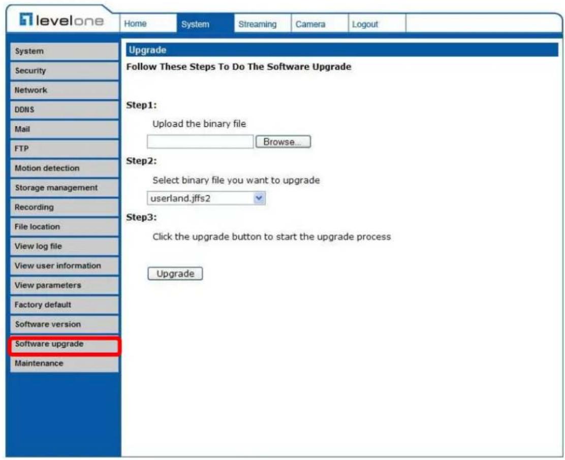

NOTE: Make sure the upgrade software file is available before carrying out software upgrade.
The procedure of software upgrade is like the following:
Step 1: Click "Browse" and select the binary file to be uploaded, ex. Userland.jffs2.


NOTE: Do not change the upgrade file name, or the system will fail to find the file.
Step 2: Pull down the upgrade binary file list and select the file you want to upgrade; in this case, select "userland.jffs2."
Step 3: Press "Upgrade". The system will first check whether the upgrade file exists or not, and then begin to upload the upgrade file. Subsequently, the upgrade status bar will display on the page. When it runs to 100% , the upgrade process is finished.

After the upgrade process is finished, the viewer will return to Home page.
Step 4: Close the video browser.
Step 5: Click "Control Panel", and then double click "Add or Remove Programs." In the "Currently install programs" list, select "DCViewer" and click the button "Remove" to uninstall the existing DC Viewer.
Step 6: Open a new web browser, re-login the IP Camera, and then allow the automatic download of DC Viewer.
4.3.17 Maintenance
Users can export configuration files to a specified location and retrieve data by uploading an existing configuration file to the IP Camera.

Export
Users can save the system settings by exporting the configuration file (.bin) to a specified location for future use. Press the "Export" button, and the popup File Download window will come out as shown below. Click "Save" and specify a desired location for saving the configuration file.

Upload
To copy an existing configuration file to the IP Camera, please first click on "Browse" to select the configuration file, and then press the "Upload" button for uploading.
4.4 Video Streaming Settings
Press the tab "Streaming" in the top of the page, and the configurable video items will display in the left column. In Streaming, the Administrator can configure specific video resolution, video compression mode, video protocol, etc. Further details of these settings will be specified in the following sections.
4.4.1 Video Resolution and Rotate Type
The video setting page is shown below:

Video Format
The IP Camera provides various video resolution like the following:
• H.264 720p (30fps) + MJPEG 720p (30fps)
• H.264 720p (30fps) + MJPEG D1 (30fps)
• H.264 720p (30fps) + MJPEG CIF (30fps)
• H.264 720p (30fps) + H.264 D1 (30fps)
• H.264 720p (30fps) + H.264 CIF (30fps)
- MJPEG 1080p (15fps);
• H.264 1080p (15fps)
Click "Save" to confirm the setting.
Text Overlay Settings
Users can select the items to display data including date/time/text on the live video pane. The maximum length of the string is 20 alphanumeric characters.
Click "Save" to confirm the Text Overlay setting.
Video Rotate Type
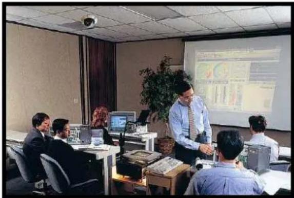
Users can change video display type if necessary. Selectable video rotate types include Normal, Flip, Mirror and 180 degree. Differences among these types are illustrated as below.
Suppose the displayed image of IP Camera is shown as the figure below.
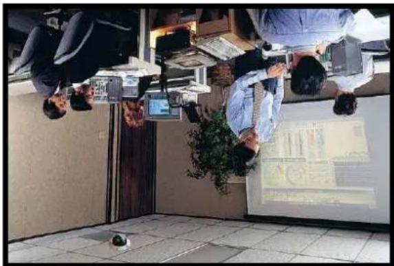
To rotate the image, users can select "Flip", for instance. Then the displayed image will be reversed as shown below.
The following is descriptions for different video rotate type.
- Flip
If select
- Mirror
If select
• 180 Degree
Selecting <180 Degree> will make the image 180° counter-/clockwise inversed.
Click "Save" to confirm the setting.
GOV Settings
Users can set the GOV length to determine the frame contracture (I-frames and P-frames) in a video stream for saving bandwidth. Longer GOV means decreasing the frequency of I-frames.
Click "Save" to confirm the GOV setting.
4.4.2 Video Compression
Users can select a proper MJPEG/H.264 compression mode in the video compression page (see the figure below), depending on the application.

Users can also decide whether to display compression information on the Home page.
Click "Save" to confirm the setting.
CBR Mode Setting
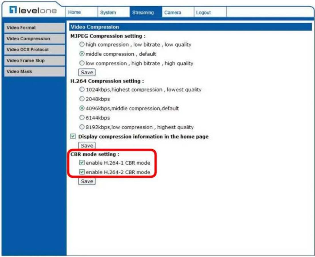
The CBR (Constant Bit Rate) mode could be the preferred bit rage mode if the bandwidth available is limited. It is important to take account of image quality while choosing to use CBR mode.
4.4.3 Video OCX Protocol
In the Video OCX protocol setting page, users can select RTP over UDP, RTP over TCP, RTSP over HTTP or MJPEG over HTTP, for streaming media over the network. In the case of multicast networking, users can select the Multicast mode. The page is shown as follows.
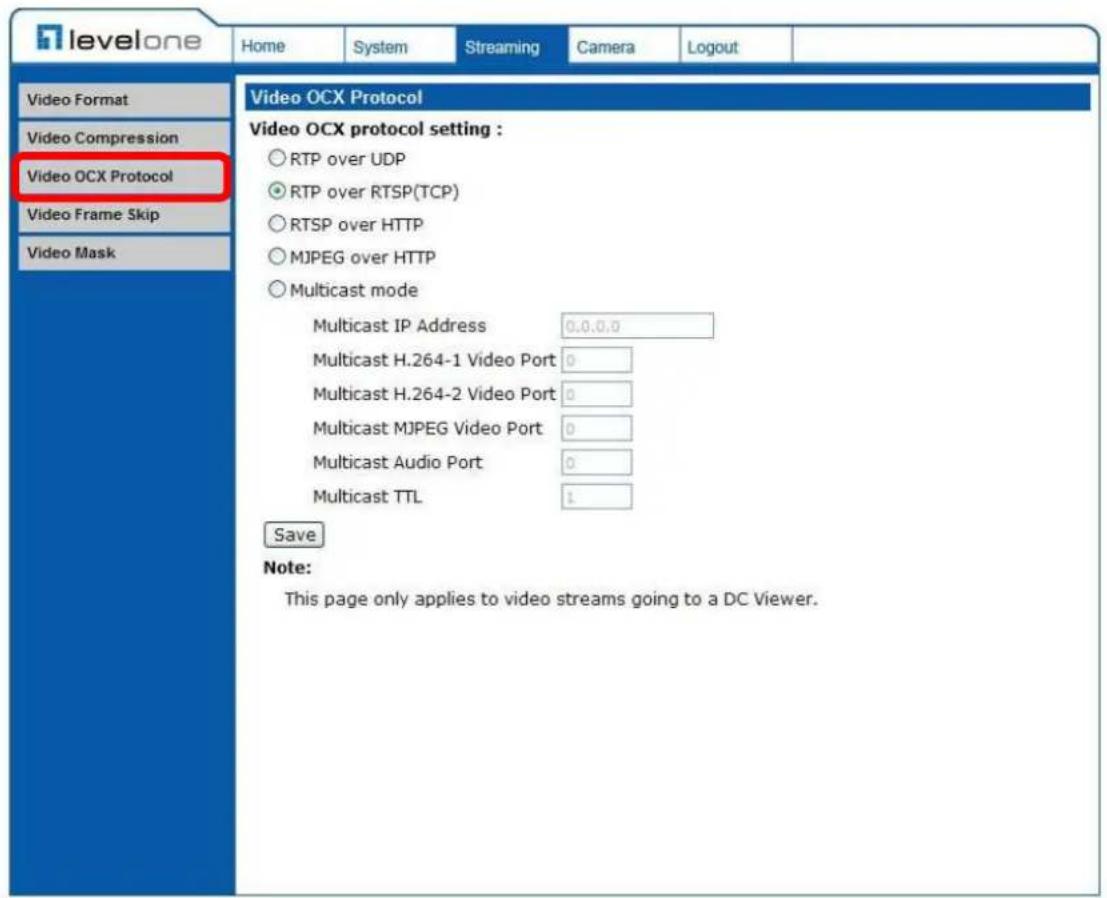
Video OCX protocol setting options include:
- RTP over UDP / RTP over RTSP(TCP) / RTSP over HTTP / MJPEG over HTTP
Select a mode according to your data delivery requirements.
- Multicast Mode Enter all required data, including multicast IP address, H.264 video port, MJPEG video port and TTL into each blank.
Click "Save" to confirm the setting.
4.4.4 Video Frame Skip
Video frame skipping is for saving bandwidth if necessary. The setting page is shown as below.

Video Frame Skip options include:
- No skipping, default
• Frame skipping at 5 frame internal
• Frame skipping at 10 frame internal
• Frame skipping to 15 frame internal

NOTE: Higher frame skipping rate will decrease video smoothness.
4.4.5 Video Mask

Active Mask Function
- Add a Mask
Check a Video Mask checkbox, and a red frame will come out in the Live Video pane at the right side. Use the mouse to drag and drop to adjust the mask's size and place it on the target zone.

NOTE: It is suggested to set the Video Mask twice bigger than the object.
- Cancel a Mask
Uncheck the checkbox of the Video Mask meant to be deleted, and the selected mask will disappear from the Live Video pane instantly.
Mask Setting
- Mask color
The selections of Mask color include red, black, white, yellow, green, blue, cyan, and magenta.
- Type
Select to change the mask type as solid or transparent.
4.5 Camera Settings
The figure below is the camera configuration page. Details of each parameter setting are described as follows.


NOTE: Please note that the function buttons will vary depending on the camera model.
4.5.1 Exposure Setting
The Exposure pull-down menu is shown as follows:

The exposure is the amount of light received by the image sensor and is determined by the width of lens diaphragm opening, the amount of exposure by the sensor (shutter speed) and other exposure parameters. With this item, users can define how the Auto Exposure function works.
Each exposure mode is specified as follows:
Full Auto Mode
In this mode, the camera's Shutter Speed, IRIS and AGC (Auto Gain Control) control circuits work together automatically to get consistent video output level. The shutter speed range is from 1 to 1/8 sec. with 4 options. Users could select suitable shutter speed according to the environmental illuminance.
Fixed Shutter Mode
In this mode, fixed shutter speed could be selected from the dropdown menu. The shutter speed range is from 1/10000 to 1 sec. with 19 options. Users could select suitable shutter speed according to the environmental illumination.
4.5.2 White Balance Setting
The White Balance pull-down menu is shown as follows:
![White Balance Auto ATW Manual Rgain: 5 [0..127] Bgain: 5 [0..127] SET](/content/2026/06/1283676/images/436f288b9161f9607b4655bb52d819dd99513ee359990dd5e1283fed3f8b9f72.jpg)
A camera needs to find reference color temperature, which is a way of measuring the quality of a light source, for calculating all the other colors. The unit for measuring this ratio is in degree Kelvin (K). Users can select one of the White Balance Control modes according to the operating environment. The following table shows the color temperature of some light sources for reference.
| Light Sources Color | Temperature in K |
| Cloudy Sky 6,000 to 8,000 | |
| Noon Sun and Clear Sky 6 | 500 |
| Household Lighting 2,500 to 3,000 | |
| 75-watt Bulb 2,820 | |
| Candle Flame 1,200 to 1,500 |
Auto Mode
The Auto Balance White mode is suitable for environment with light source having color temperature in the range roughly from 2700 \~ 8000K.
ATW Mode (Auto Tracking White Balance)
With Auto Tracking White Balance function, the white balance in a scene will be automatically adjusted while temperature color is changing. The ATW Mode is suitable for environment with light source having color temperature in the range roughly from 2450 \~ 10500K.
Manual Mode
In this mode, users can change the White Balance value manually. Users can select a number between 0 \~127 of "Rgain/ Bgain" item to gain the red/blue illuminant on the Live Video Pane. Press
4.5.3 Brightness Setting

Users can adjust the image's brightness by adjusting the item. To increase video brightness, select a bigger number. Press
4.5.4 Sharpness Setting

Increasing the sharpness level can make the image looked sharper; especially enhance the object's edge. Press
4.5.5 Contrast Setting

Camera image contrast level is adjustable; please select ranging from -6 to +19. Press
4.5.6 Saturation Setting

Camera image saturation level is adjustable; please select ranging from -6 to +19. Press
4.5.7 Hue Setting

Camera image hue level is adjustable; please select ranging from -12 to +13.
Press
4.5.8 TV System Setup
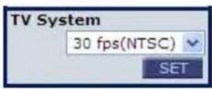
Select the video format that matches the present TV system.
4.6 Logout
Press the tab "Logout" in the top of the page, and the login window will pop up. This enables login with another user name.

Appendix A: Technical Specifications
| Camera Full HD | ||
| Image Sensor 1/2.7" Progressive CMOS | ||
| Picture Elements 1920(H) x 1080(V) | ||
| Minimum Illumination 0.1 lux @ F 1.6 | ||
| Shutter Speed 1~ 1/10000 sec. | ||
| White Balance Manual / AWB / ATW | ||
| Lens | ||
| Fixed Lens F 1.5 / f = 4.0 mm | ||
| FOV 78° (f = 4.0 mm) | ||
| Operation | ||
| Video Compression H.264/MJPEG | ||
| Video Streaming | Simultaneous H.264 + MJPEG Simultaneous H.264 + H.264 | |
| Resolution | H.264 Full-HD 1080p / HD 720p / D1 / CIF | |
| MJPEG Full-HD 1080p / HD 720p / D1 / CIF | ||
| Frame Rate HD 25 / 30 fps , Full HD 15 fps | ||
| Image Setting | Brightness Manual | |
| Exposure | Auto / Manual | |
| Sharpness | Manual | |
| Contrast | Manual | |
| White Balance | Auto / Manual | |
| Saturation | Manual | |
| Hue | Manual | |
| Digital Zoom | Support | |
| Motion detection | On / Off | |
| Privacy Mask | 2 | |
| Privacy Mask Type | Transparent, Color | |
| Network | ||
| Interface | 10/100Mbps Ethernet (RJ-45) | |
| Protocol | TCP/IP, UDP, RTP, RTSP, HTTP, ICMP, FTP, SMTP, DHCP, PPPoE, UPnP and IGMP | |
| Password Levels | User and Administrator | |
| Internet Browser | Internet Explorer (6.0+) | |
| User Account | 20 | |
| Mechanical | ||
| Lens Mounting | M12 Board Lens | |
| Connectors | Ethernet | RJ-45 |
| Micro SD; optional | SDHC support | |
| General | ||
| Operating Temperature | -20° ~ 50°C Humidity: 10% to 90%, No Condensation | |
| Power Source | PoE | |
| Power Consumption | 3.8W | |
| Regulatory CE, FCC, RoHS Compliant | ||
| Dimension | 117 × 50 mm (4.6 x 2.0 Inches) | |
| Weight 180 g (0.40 lbs) | ||
Appendix B: Internet Security Settings
If ActiveX control installation is blocked, please either set Internet security level to default or change ActiveX controls and plug-ins settings.
Internet Security Level: Default
Step 1: Start the Internet Explorer (IE).
Step 2: Select

Step 3: Click the

Step 4: Down the page, press "Default Level" (see the figure above) and click "OK" to confirm the setting. Close the browser window, and open a new one later when accessing the IP Camera.
ActiveX Controls and Plug-ins Settings
Step 1\~3: Refer to the previous section above.
Step 4: Down the page, press "Custom Level" (see the figure below) to change ActiveX controls and plug-ins settings.

The Security Settings screen is displayed as below:
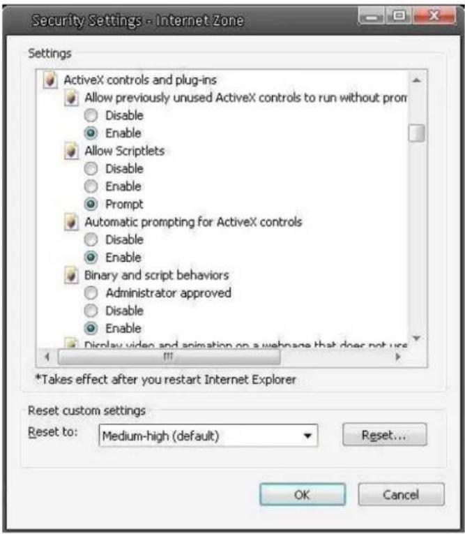
Step 5: Under "ActiveX controls and plug-ins", set ALL items (as listed below) to
ActiveX controls and plug-ins settings:
- Automatic prompting for ActiveX controls
- Binary and scrip behaviors
- Download signed ActiveX controls
- Download using ActiveX controls
- Initialize and script ActiveX not marked as safe
- Run ActiveX controls and plug-ins
- Script ActiveX controls marked safe for scripting
Step 6: Click
Step 7: Click
Step 8: Close the browser window, and restart a new one later for accessing the IP Camera.
Appendix C: DC Viewer Download Procedure
The procedure of DC Viewer software download is specified as follows.
Step 1: In the DC Viewer installation page, click "Next" for starting installing.
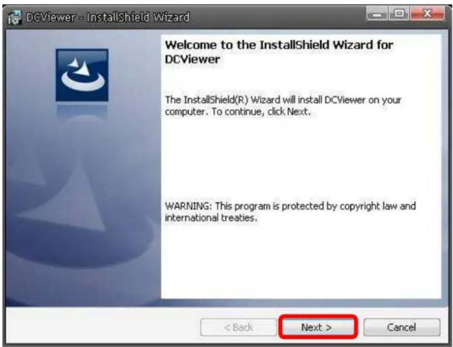
Step 2: Setup starts. Please wait for a while until the loading bar runs out.
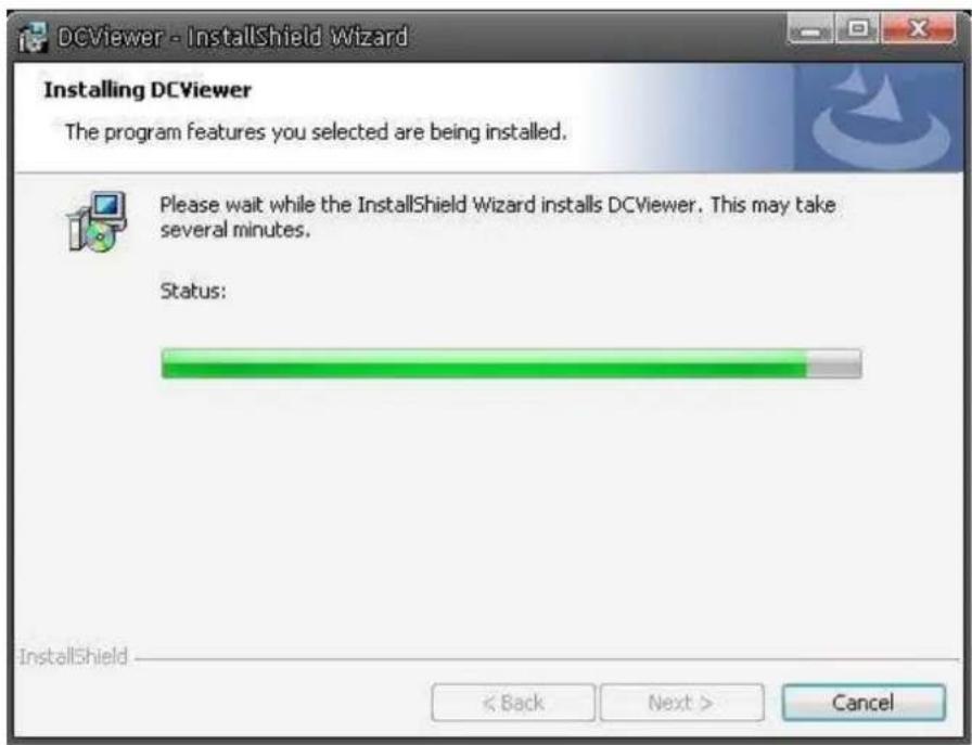
Step 3: Click "Finish" to close the DC Viewer installation page.

Then, the IP Camera's Home page will display as follows:
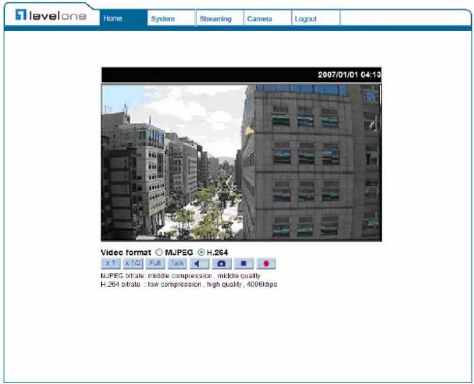

NOTE: Please note that the function buttons will vary depending on the camera model.
Appendix D: Install UPnP Components
Please follow the instructions below to install UPnP components.
Step 1: Go to "Start", click on "Control Panel", and then double click "Add or Remove Programs".

Step 2: Click on "Add/Remove Windows Components" in the Add or Remove Programs page..
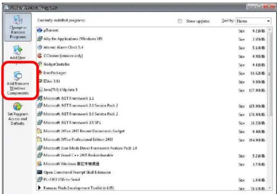
Step 3: Select "Networking Services" from the Components list in the Windows Components Wizard window, and then click "Details".

Step 4: Select "UPnP User Interface" in the Networking Services' subcomponents list and then click "OK".

Step 5: Click "Next" in the Windows Components Wizard page.

Step 6: Click "Finish" to complete installation.




- TABLE OF CONTENTS
- INTRODUCTION......3
- PREPARATIONS FOR IP CAMERA SETUP ....6
- ACCESSING CAMERA 6
- CONFIGURATION & OPERATION....15
- 4.4 VIDEO STREAMING SETTINGS ....50
- 4.5 CAMERA SETTINGS....58
- DEFAULT ID / PASSWORD
- LOGIN ID PASSWORD
- INTRODUCTION
- 1.1 FEATURES
- 1.2 PACKAGE CONTENTS
- 1.3 CAMERA OVERVIEW
- PREPARATIONS FOR IP CAMERA SETUP
- 2.1 SYSTEM REQUIREMENTS
- ACCESSING CAMERA
- DEVICE SEARCH SOFTWARE SETUP
- DEVICE SEARCH
- EXAMPLE OF CHANGING IP CAMERA'S NETWORK PROPERTY
- USING RECORDING SOFTWARE
- INSTALLING DC VIEWER SOFTWARE ONLINE
- ADMINISTRATOR/USER PRIVILEGES
- IMAGE AND FOCUS ADJUSTMENT
- CONFIGURATION & OPERATION
- 4.1 BROWSER-BASED VIEWER INTRODUCTION
- HOME
- SYSTEM SETTING
- STREAMING SETTING
- CAMERA SETTING
- LOGOUT
- 4.2 HOME PAGE
- SCREEN SIZE ADJUSTMENT
- DIGITAL ZOOM CONTROL
- SNAPSHOT BUTTON
- VIDEO STREAMING PAUSE /RESTART BUTTON
- RECORDING BUTTON
- 4.3 SYSTEM RELATED SETTINGS
- 4.3.1 HOST NAME AND SYSTEM TIME SETTING
- HOST NAME
- TIME ZONE
- ENABLE DAYLIGHT SAVING TIME
- SYNC WITH COMPUTER TIME
- MANUAL
- SYNC WITH NTP SERVER
- 4.3.2 SECURITY
- ROOT PASSWORD
- ADD USER
- I/O ACCESS
- CAMERA CONTROL
- TALK/LISTEN
- MANAGE USER
- DELETE USER
- EDIT USER
- 4.3.3 NETWORK
- GET IP ADDRESS AUTOMATICALLY (DHCP)
- USE FIXED IP ADDRESS
- IP ADDRESS
- SUBNET MASK
- DEFAULT GATEWAY
- PRIMARY DNS
- SECONDARY DNS
- USE PPPOE
- ADVANCED
- WEB SERVER PORT
- RTSP PORT
- MJPEG OVER HTTP PORT
- UPNP SETTING
- ENABLE UPNP
- ENABLE UPNP PORT FORWARDING
- FRIENDLY NAME
- 4.3.4 DDNS
- ENABLE DDNS
- PROVIDER
- USERNAME/E-MAIL
- PASSWORD/KEY
- 4.3.5 MAIL
- 4.3.6 FTP
- 4.3.7 MOTION DETECTION
- MOTION DETECTION
- MOTION DETECTION SETTING
- TRIGGERED ACTION (MULTI-OPTION)
- UPLOAD IMAGE BY E-MAIL
- FILE NAME
- SAVE
- 4.3.8 STORAGE MANAGEMENT
- DEVICE INFORMATION
- DEVICE SETTING
- DISK CLEANUP SETTING
- RECORDING LIST
- REMOVE
- SORT
- DOWNLOAD
- 4.3.9 RECORDING
- ACTIVATING MICRO SD/SDHC CARD RECORDING
- TERMINATING MICRO SD/SDHC CARD RECORDING
- 4.3.10 FILE LOCATION
- 4.3.11 VIEW LOG FILE
- 4.3.12 VIEW USER INFORMATION
- VIEW USER LOGIN INFORMATION
- USER: ROOT
- VIEW USER PRIVILEGE
- USER: 1:1:0:1
- 4.3.13 VIEW PARAMETERS
- 4.3.14 FACTORY DEFAULT
- SET DEFAULT
- REBOOT
- 4.3.15 SOFTWARE VERSION
- 4.3.16 SOFTWARE UPGRADE
- 4.3.17 MAINTENANCE
- EXPORT
- UPLOAD
- 4.4 VIDEO STREAMING SETTINGS
- 4.4.1 VIDEO RESOLUTION AND ROTATE TYPE
- VIDEO FORMAT
- TEXT OVERLAY SETTINGS
- VIDEO ROTATE TYPE
- GOV SETTINGS
- 4.4.2 VIDEO COMPRESSION
- CBR MODE SETTING
- 4.4.3 VIDEO OCX PROTOCOL
- 4.4.4 VIDEO FRAME SKIP
- 4.4.5 VIDEO MASK
- ACTIVE MASK FUNCTION
- ADD A MASK
- CANCEL A MASK
- MASK SETTING
- MASK COLOR
- TYPE
- 4.5 CAMERA SETTINGS
- 4.5.1 EXPOSURE SETTING
- FULL AUTO MODE
- FIXED SHUTTER MODE
- 4.5.2 WHITE BALANCE SETTING
- AUTO MODE
- ATW MODE (AUTO TRACKING WHITE BALANCE)
- MANUAL MODE
- 4.5.3 BRIGHTNESS SETTING
- 4.5.4 SHARPNESS SETTING
- 4.5.5 CONTRAST SETTING
- 4.5.6 SATURATION SETTING
- 4.5.7 HUE SETTING
- 4.5.8 TV SYSTEM SETUP
- 4.6 LOGOUT
- APPENDIX B: INTERNET SECURITY SETTINGS
- INTERNET SECURITY LEVEL: DEFAULT
- ACTIVEX CONTROLS AND PLUG-INS SETTINGS
- APPENDIX C: DC VIEWER DOWNLOAD PROCEDURE
- APPENDIX D: INSTALL UPNP COMPONENTS
Brand : LEVELONE
Model : FCS-3071
Category : Surveillance Camera