PT Cruiser convertible (2005) - Car Chrysler - Free user manual and instructions
Find the device manual for free PT Cruiser convertible (2005) Chrysler in PDF.


| Product Type | Convertible Car |
| Brand | Chrysler |
| Model | PT Cruiser Convertible |
| Year | 2005 |
| Engine | 2.4L Inline-4 |
| Horsepower | 150 hp @ 5200 rpm |
| Torque | 165 lb-ft @ 4000 rpm |
| Transmission | 4-speed automatic or 5-speed manual |
| Fuel Economy | 22 mpg combined (EPA est.) |
| Fuel Tank Capacity | 15.7 gallons |
| Weight | Approx. 3,200 lbs (1,451 kg) |
| Length | 168.8 in (4,288 mm) |
| Width | 67.1 in (1,704 mm) |
| Height | 61.5 in (1,562 mm) |
| Wheelbase | 103.0 in (2,616 mm) |
| Convertible Top | Power-operated soft top |
| Seating Capacity | 5 passengers |
| Safety Features | ABS, dual front airbags, side airbags |
| Maintenance | Oil change every 3,000-5,000 miles |
| Repair Parts | Widely available; check owner's manual |
Frequently Asked Questions - PT Cruiser convertible (2005) Chrysler
User questions about PT Cruiser convertible (2005) Chrysler
0 question about this device. Answer the ones you know or ask your own.
Ask a new question about this device
Download the instructions for your Car in PDF format for free! Find your manual PT Cruiser convertible (2005) - Chrysler and take your electronic device back in hand. On this page are published all the documents necessary for the use of your device. PT Cruiser convertible (2005) by Chrysler.
USER MANUAL PT Cruiser convertible (2005) Chrysler
■Vehicle Identification Number....6
■Vehicle Modifications / Alterations ..... 7
4 INTRODUCTION
INTRODUCTION
This manual has been prepared with the assistance of service and engineering specialists to acquaint you with the operation and maintenance of your new vehicle. It is supplemented by a Warranty Information Booklet and various customer oriented documents. You are urged to read these publications carefully. Following the instructions and recommendations in this manual will help assure safe and enjoyable operation of your vehicle.
NOTE: After you read the manual, it should be stored in the vehicle for convenient reference and remain with the vehicle when sold, so that the new owner will be aware of all safety warnings.
When it comes to service, remember that your dealer knows your vehicle best, has the factory-trained technicians and genuine Mopar® parts, and is interested in your satisfaction.
WARNING!
Engine exhaust, some of its constituents, and certain vehicle components contain or emit chemicals known to the State of California to cause cancer and birth defects or other reproductive harm. In addition, certain fluids contained in vehicles and certain products of component wear contain or emit chemicals known to the State of California to cause cancer and birth defects or other reproductive harm.
HOW TO USE THIS MANUAL
Consult the table of contents to determine which section contains the information you desire.
The detailed index, at the rear of this manual, contains a complete listing of all subjects.
Consult the following table for a description of the symbols that may be used on your vehicle or throughout this owner's manual:
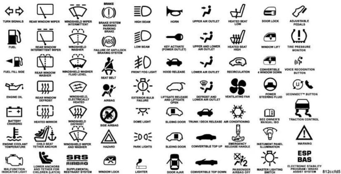
6 INTRODUCTION
WARNINGS AND CAUTIONS
This manual contains WARNINGS against operating procedures which could result in an accident or bodily injury. It also contains CAUTIONS against procedures which could result in damage to your vehicle. If you do not read this entire manual you may miss important information. Observe all Warnings and Cautions.
VEHICLE IDENTIFICATION NUMBER
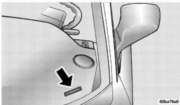
Vehicle Identification Number (VIN) is found on the driver's front corner of the instrument panel, visible through the windshield. This number also appears on the vehicle registration or title.
natural_image
Diagram of a car interior showing a hand pressing down a valve with a black arrow indicating the direction (no text or symbols present)Vehicle Identification Number
VEHICLE MODIFICATIONS / ALTERATIONS
WARNING!
Any modifications or alterations to this vehicle could seriously affect its roadworthiness and safety and may lead to an accident resulting in serious injury or death.
THINGS TO KNOW BEFORE STARTING YOUR VEHICLE
CONTENTS
■A Word About Your Keys....12
□Ignition Key Removal....12
□Locking Doors With The Key ..... 1 4
□Key-In-Ignition Reminder....14
■Sentry Key....1 4
□Replacement Keys....16
□Sentry Key Programming....16
□General Information....17
■ Steering Wheel Lock — If Equipped .....17
□If You Wish To Manually Lock The Steering Wheel....17
□To Release The Steering Wheel Lock....17
□ Automatic Transaxle Ignition Interlock System . .18
■Door Locks 18
□Manual Door Locks....1 8
□Power Door Locks 19
□ Central Locking/Unlocking .....20
□Automatic Door Locks....20
10 THINGS TO KNOW BEFORE STARTING YOUR VEHICLE
■Remote Keyless Entry 2 1
□To Unlock The Doors....2 1
□To Lock The Doors....2 2
□Horn Chirp Feature 2 2
□Using The Panic Alarm....2 2
□To Program Transmitters....23
□General Information....23
□Transmitter Battery Service....24
■Security Alarm System....2 5
□To Set The Alarm....25
□To Disarm The System....26
□Security System Manual Override....26
■Deck Lid....26
□Power Deck Lid Release....27
Emergency Deck Lid Release Latch....28
■Power Windows....28
□Auto Down Feature....29
□Wind Buffeting 30
■Occupant Restraints....30
□Lap/Shoulder Belts . . . . . . . . . . . . . . . . . . . . . . . . . . . . . . . . . . . . . . . . . . . . . . . 31
□Lap/Shoulder Belt Untwisting Procedure ..... 3 7
□Seat Belt Pretensioners....39
□Seat Belts And Pregnant Women . . . . . . . . . . . 3 9
☐Driver And Front Passenger Supplemental Restraint System (SRS) - Airbag ..... 4 0
□Child Restraint 49
■Engine Break-In Recommendations....56
■Safety Tips....57
□Exhaust Gas....57
THINGS TO KNOW BEFORE STARTING YOUR VEHICLE 11
□Safety Checks You Should Make Inside The Vehicle....57
☐Periodic Safety Checks You Should Make Outside The Vehicle....58
12 THINGS TO KNOW BEFORE STARTING YOUR VEHICLE
A WORD ABOUT YOUR KEYS
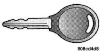
The dealer that sold you your new vehicle has the key code numbers for your vehicle locks. These numbers can be used to order duplicate keys from your dealer. Ask your dealer for these numbers and keep them in a safe place.
natural_image
Illustration of a key with a handle and keyhole (no text or symbols)Vehicle Key
The double sided keys may be inserted into the locks with either side up.
Ignition Key Removal
Automatic Transaxle
Place the shift lever in PARK and make sure that the shift knob push button has returned to the out position. Turn the ignition switch to the OFF position, then to the LOCK position, and remove the key.
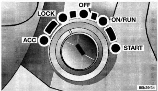
Ignition Key Positions
THINGS TO KNOW BEFORE STARTING YOUR VEHICLE 13
NOTE: If you try to remove the key before you place the lever in PARK, the key may become trapped temporarily in the ignition cylinder. If this occurs, rotate the key to the right slightly, then remove the key as described. If a malfunction occurs, the system will trap the key in the ignition cylinder to warn you that this safety feature is inoperable. The engine can be started and stopped but the key cannot be removed until you obtain service.
Manual Transaxle
Depress and hold the release button located between the ignition switch and the instrument panel. Turn the ignition switch to the LOCK position and remove the key.
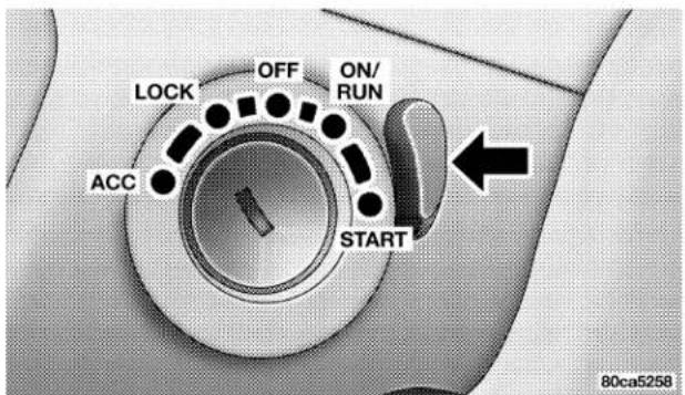
Ignition Key Positions
14 THINGS TO KNOW BEFORE STARTING YOUR VEHICLE
WARNING!
Leaving children in a vehicle unattended is dangerous for a number of reasons. A child or others could be injured. Children should be warned not to touch the parking brake, brake pedal or the gear selector lever. Don't leave the keys in the ignition. A child could operate power windows, other controls, or move the vehicle.
CAUTION!
An unlocked car is an invitation to thieves. Always remove key from the ignition and lock all doors when leaving the vehicle unattended.
Locking Doors With The Key
You can insert the key with either side up. To lock the door, turn the key rearward, to unlock the door, turn the key forward. See Section 7 of this manual for door lock lubrication.
Key-In-Ignition Reminder
Opening the driver's door when the key is in the ignition, sounds a signal to remind you to remove the key.
NOTE: With the driver's door open, and the key in the ignition, the power door locks will not function.
SENTRY KEY
The Sentry Key Immobilizer System prevents unauthorized operation of the vehicle by disabling the engine. The system will shut the engine off after 2 seconds of running if an invalid key is used to start the vehicle. This system utilizes ignition keys which have an electronic
chip (transponder) embedded into them. Only keys that have been programmed to the vehicle can be used to start and operate the vehicle.
The Sentry Key Immobilizer System does not need to be armed or activated. Operation of the system is automatic regardless of whether or not the vehicle is locked or unlocked. During normal operation, the Theft Alarm/Immobilizer Light will come on for three (3) seconds immediately after the ignition switch is turned on for a bulb check. Afterwards, if the bulb remains on, this indicates a problem with the electronics.
If the bulb begins to flash after the bulb check, this indicates that an invalid key has been used to start the vehicle. Both of these conditions will result in the engine being shut off after two (2) seconds of running.
Keep in mind that a key which has not been programmed is also considered an invalid key even if it is cut to fit the ignition lock cylinder for that vehicle.
If the Theft Alarm/Immobilizer Light comes on during normal vehicle operation (vehicle has been running for longer than 10 seconds), a fault has been detected in the electronics and the vehicle should be serviced as soon as possible.
NOTE:
- The Sentry Key Immobilizer System is not compatible with remote starting systems. Use of these systems may result in vehicle starting problems and loss of security protection.
- Exxon/Mobil Speed Pass, ^TM additional Sentry Keys, or any other transponder equipped components on the same keychain will not cause a key-related (transponder) fault unless the additional part is physically held against the ignition key being used when starting the vehicle. Cell phones, pagers, or other RF electronics will not cause interference with this system.
All of the keys provided with your new vehicle have been programmed to the vehicle electronics.
Replacement Keys
NOTE: Only keys that have been programmed to the vehicle electronics can be used to start the vehicle. Once a Sentry Key has been programmed to a vehicle, it can not be programmed to any other vehicle.
At the time of purchase, the original owner is provided with a four digit PIN number. This number is required for dealer replacement of keys. Duplication of keys may be performed at an authorized dealer or by using the Customer Key Programming procedure. This procedure consists of programming a blank key to the vehicle electronics. A blank key is one which has never been programmed.
NOTE: When having the Sentry Key Immobilizer System serviced, bring all vehicle keys with you to the dealer.
Sentry Key Programming
You can program new keys to the system if you have two valid sentry keys by performing the following procedure:
- Cut the additional Sentry Key Transponder blank(s) to match the ignition switch lock cylinder key code.
- Insert the first valid key into the ignition switch and turn the ignition switch ON for at least 3 seconds but no longer than 15 seconds. Turn the ignition switch OFF and remove the first key.
-
Insert the second valid key and turn the ignition switch ON within 15 seconds. After ten seconds a chime will sound and the Theft Alarm Light will begin to flash. Turn the ignition switch OFF and remove the second key.
-
Insert a blank Sentry Key into the ignition switch and turn the ignition switch ON within 60 seconds. After 10 seconds a single chime will sound. The Theft Alarm Light will stop flashing, turn on for 3 seconds; then turn off.
The new Sentry Key has been programmed.
Repeat this procedure to program up to a total of 8 keys. If you do not have a programmed sentry key, contact your dealer for details.
General Information
The Sentry Key system complies with FCC rules part 15 and with RSS-210 of Industry Canada. Operation is subject to the following conditions:
- This device may not cause harmful interference.
- This device must accept any interference that may be received, including interference that may cause undesired operation.
STEERING WHEEL LOCK — IF EQUIPPED
Your vehicle may be equipped with a passive steering wheel lock. This lock prevents steering the vehicle without the ignition key. If the steering wheel is moved no more than 1/2 turn in either direction and the key is not in the ignition switch, the steering wheel will lock.
If You Wish To Manually Lock The Steering Wheel:
With the engine running, turn the steering wheel upside down, turn off the engine and remove the key. Turn the steering wheel slightly in either direction until the lock engages.
To Release The Steering Wheel Lock:
Insert the key in the ignition switch and start the engine. If the key is difficult to turn, move the wheel slightly to the right or left to disengage the lock.
NOTE: If you turned the wheel to the right to engage the lock, you must turn the wheel slightly to the right to
18 THINGS TO KNOW BEFORE STARTING YOUR VEHICLE
disengage it. If you turned the wheel to the left to engage the lock, turn the wheel slightly to the left to disengage it.
Automatic Transaxle Ignition Interlock System
This system prevents the key from being removed unless the shift lever is in PARK and the shift knob push-button is out. It also prevents shifting out of PARK unless the key is in the OFF, or ON positions.
DOOR LOCKS
Manual Door Locks
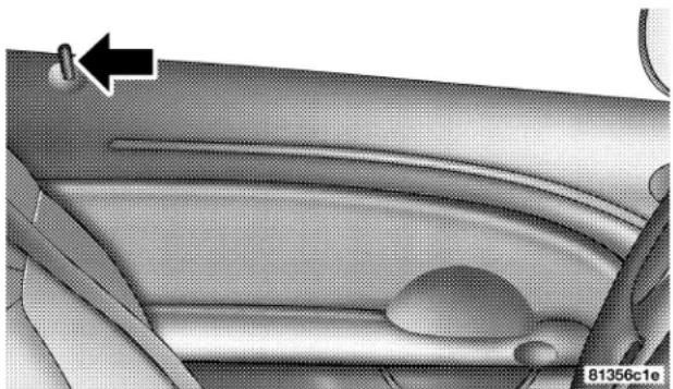
Use the manual door lock plunger to lock the doors from inside the vehicle. If the plunger is down when the door is closed, the door will lock. Therefore, make sure the keys are not inside the vehicle before closing the door.
natural_image
Interior view of a car dashboard and seat area showing the wheel rim and seat (no text or symbols visible)Door Lock Plunger
WARNING!
For personal security, and safety in the event of an accident, lock the vehicle doors as you drive as well as when you park and leave the vehicle.
WARNING!
When leaving the vehicle always remove the key from the ignition lock, and lock your vehicle. Do not leave children unattended in the vehicle, or with access to an unlocked vehicle. Unsupervised use of vehicle equipment may cause severe personal injuries and death.
CAUTION!
An unlocked vehicle is an invitation to thieves. Always remove the key from the ignition and lock all of the doors when leaving the vehicle unattended.
Power Door Locks
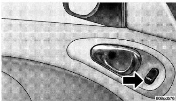
A door lock switch is on each front door panel. Press this switch to lock or unlock the doors.
natural_image
Close-up of a car's side window with a black arrow pointing to the handle (no text or symbols visible)Power Door Lock Switch
20 THINGS TO KNOW BEFORE STARTING YOUR VEHICLE
Central Locking/Unlocking
All vehicle doors and deck lid are locked with the first turn of the key to the LOCK position. The double unlock activation feature requires you to turn the key in the cylinder lock two times within five seconds to UNLOCK all vehicle doors at once. You may turn this feature off and unlock all the doors with one turn of the key by following these instructions.
NOTE: Steps 2 and 3 must be completed within 10 seconds.
- Close all doors and place the key in the ignition switch.
- Cycle the ignition switch ON/OFF four times ending in the OFF position.
-
Press the interior door lock switch to the UNLOCK position.
-
A single chime will sound to signify that you have successfully disabled the double activation feature.
You can turn the feature back on by repeating the above mentioned procedure.
Automatic Door Locks
The doors will lock automatically if:
- all doors are closed,
- vehicle speed is above 15 mph (24 km/h),
- the accelerator pedal is depressed.
The Automatic Door Locks can be enabled or disabled by performing the following procedure:
NOTE: Steps 2 and 3 must be completed within 10 seconds.
-
Close all doors and place the key in the ignition switch.
-
Cycle the ignition switch ON/OFF four times ending in the OFF position.
- Press the interior door lock switch to the LOCK position.
- A single chime will sound to signify that you have successfully completed the programming.
You can turn the feature back on by repeating the above mentioned procedure.
REMOTE KEYLESS ENTRY
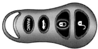
This system allows you to lock or unlock the doors and activate the panic alarm from distances up to about 23 feet (7 meters) using a hand held transmitter. The transmitter need not be pointed at the vehicle to activate the system.
80b31f52
To Unlock The Doors:
Press and release the UNLOCK button on the key fob once to unlock the driver's door, or twice within five seconds to unlock all doors, the park lights will also flash twice. The interior lights also come on and remain on for about 30 seconds when you unlock the doors.
NOTE: You may turn off this feature and unlock all doors with one press of the button by following the procedure shown in the Central Locking/Unlocking paragraph.
22 THINGS TO KNOW BEFORE STARTING YOUR VEHICLE
To Lock The Doors:
Press and release the LOCK button to lock all doors. The park lights will flash and the horn will chirp to acknowledge the signal.
Horn Chirp Feature
The horn chirp that signals that the doors have been locked can be turned on or off by using the following procedure:
- Insert the key into the ignition switch and turn the switch to the ON position.
- Press and hold the Unlock button on the transmitter for between four and ten seconds.
- Continue to hold the Unlock button and press the Lock button.
- Release both buttons.
A chime will sound to signify that the process is complete.
Using The Panic Alarm:
To turn on the panic alarm feature, press and release the PANIC button. When the panic alarm is on the headlights and park lights will flash, the horn will pulse on and off and the interior lights will turn on.
The panic alarm will stay on for 3 minutes unless you press the PANIC button a second time, or until vehicle speed reaches 15 mph (24 km/h).
NOTE: When you turn off the panic alarm by pressing the PANIC button a second time, you may have to be closer to the vehicle due to the radio frequency noises of the system.
To Program Transmitters
Up to four transmitters can be programmed to your vehicle. Your new vehicle was shipped with two transmitters. See your dealer for additional transmitters.
Additional transmitters can be programmed to the system by using the following procedure:
- Insert the key into the ignition switch and turn the switch to the ON position.
- Press and hold the Unlock button on the transmitter between four and ten seconds.
- Continue to hold the Unlock button and press the Panic button. A chime will sound to indicate that the transmitter programming mode has been entered.
-
Press a button on all transmitters to be programmed to the system, including any previously programmed transmitters. A chime will sound when each transmitter has been programmed.
-
Turn the ignition switch off to exit the transmitter programming mode.
General Information
This device complies with FCC rules part 15 and with RSS-210 of Industry Canada. Operation is subject to the following conditions:
• This device may not cause harmful interference.
- This device must accept any interference that may be received, including interference that may cause undesired operation.
If your transmitter fails to operate from a normal distance, check for these two conditions.
- Weak batteries in transmitter. The expected life of batteries is from one to two years.
- Closeness to a radio transmitter such as a radio station tower, airport transmitter, and some mobile or CB radios.
24 THINGS TO KNOW BEFORE STARTING YOUR VEHICLE
Transmitter Battery Service
The recommended replacement battery is 2016 or its equivalent.
NOTE: Do not touch the battery terminals that are on the back housing or the printed circuit board.
- With the transmitter buttons facing down, use a thin coin to pry the two halves of the transmitter apart. Make sure not to damage the rubber gasket during removal.
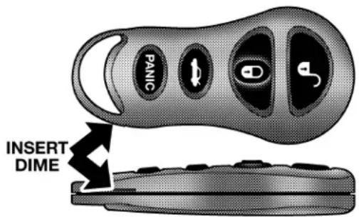
80b31f53
- Remove and replace the batteries. Avoid touching the new batteries with your fingers. Skin oils may cause battery deterioration. If you touch a battery, clean it with rubbing alcohol.
- To reassemble the transmitter case snap two halves together. Make sure there is an even gap between the two halves. Test transmitter operation.
SECURITY ALARM SYSTEM
The system monitors the doors, deck lid, and ignition switch for unauthorized operation.
If something triggers the alarm, the system will signal for about 18 minutes. For the first 3 minutes the horn will sound and the headlights, park lights, tail lights and the indicator light in the cluster will flash. Then the exterior lights will flash for another 15 minutes.
If the monitored system, which triggered the alarm is deactivated the alarm will continue to sound until 3 minutes of alarm time is reached. If the monitored system, which triggered the alarm is deactivated after the alarm has been on for 3 minutes the alarm will shut off immediately.
To set the alarm:
- Remove the keys from the ignition switch and get out of the vehicle.
- Lock the door using either the door key, power door lock switch, or the Keyless Entry Transmitter and close all doors.
- The indicator light in the instrument cluster will flash rapidly for 16 seconds. This shows that the system is arming. During this period, if a door is opened, the ignition switch is turned ON, or the power door locks are unlocked in any manner, the system will automatically disarm. After 16 seconds the indicator light will flash slowly. This shows that the system is fully armed.
26 THINGS TO KNOW BEFORE STARTING YOUR VEHICLE
To disarm the system:
Unlock a front door/deck lid using either the key or the Keyless Entry Transmitter.
Starting the vehicle with a valid Sentry key will disarm the system. A valid key is one that is programmed to that particular vehicle. A valid key will disarm the system, an invalid key will trigger the alarm.
Tamper Alert
If the horn sounds 3 times when you unlock a front door using either a key or the Keyless Entry Transmitter, the alarm has been activated. Check the vehicle for tampering.
Security System Manual Override
The system will not arm if you lock the doors using the manual door lock plunger.
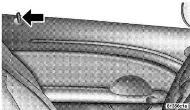
natural_image
Interior view of a car dashboard with seatbelt and steering wheel (no visible text or symbols)Door Lock Plunger
DECK LID
NOTE: The key that is used to start the vehicle is also used to lock or unlock the doors and open the deck lid.
To open the deck lid, insert the key into the lock and turn to the right. The deck lid can also be opened using the remote keyless entry or by using the power deck lid release switch, located in the glove box.
WARNING!
- Driving with the deck lid open can allow poisonous exhaust gases into your vehicle. You and your passengers could be injured by these fumes. Keep the deck lid closed when you are operating the vehicle.
- If you are required to drive with the deck lid open, make sure that all windows are closed, and the climate control blower switch is set at high speed. DO NOT use the recirculation mode.
Gas props support the deck lid in the open position. However, because the gas pressure drops with temperature, it may be necessary to assist the props when opening the deck lid in cold weather.
Power Deck Lid Release
You can open the deck lid by pressing the Remote Keyless Entry Button or from inside the vehicle, using the switch located inside the glove box. The power deck lid release switch is disabled when the vehicle speed exceeds 5 mph (8 km/h), or when the vehicle theft alarm is in the armed or alarming state.
28 THINGS TO KNOW BEFORE STARTING YOUR VEHICLE
EMERGENCY DECK LID RELEASE LATCH
WARNING!
Do not allow children to have access to the trunk, either by climbing into the trunk from outside, or through the inside of the vehicle. Always close the deck lid when your vehicle is unattended. Once in the trunk, young children may not be able to escape, even if they entered through the rear seat. If trapped in the trunk, children can die from suffocation or heat stroke.
As a security measure, an emergency deck lid release lever is built into the deck lid latching mechanism. In the event of an individual being locked inside the trunk, the trunk can be simply opened by pulling on the glow-in-the-dark lever attached to the deck lid latching mechanism. See following picture.
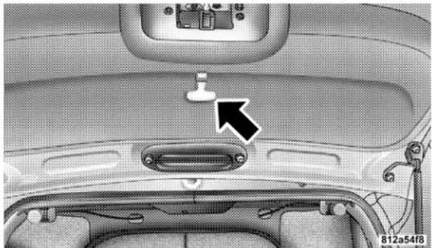
natural_image
Interior view of a car showing the rear intake and dashboard with a white connector and a black arrow pointing to a component (no text or symbols visible)Emergency Deck Lid Release Handle
POWER WINDOWS
The power window switches are located on the instrument panel above the A/C controls. The top left switch controls the left front window and the top right switch controls the right front window.
The lower left switch controls the left rear passenger's window and the lower right switch controls the right rear passenger's window.
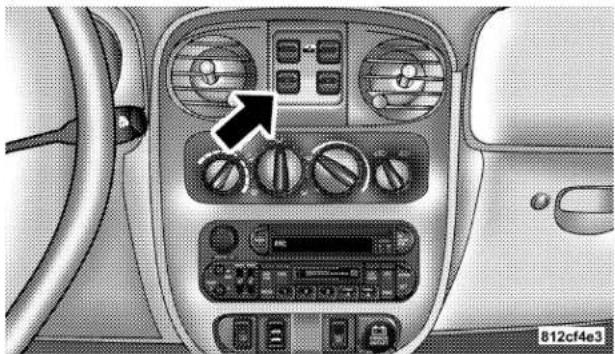
natural_image
Interior view of a car dashboard with air conditioners and control panels (no visible text or symbols)Power Window Switches
WARNING!
Never leave children in a vehicle, with the keys in the ignition switch. Occupants, particularly unattended children, can become entrapped by the windows while operating the power window switches. Such entrapment may result in serious injury or death.
Auto Down Feature
The driver's and passenger's front window switches have an auto down feature. Press the window switch past the detent, release, and the window will go down automatically. Press the switch a second time in either direction to stop the window.
To open the window part way, press the window switch part way and release it when you want the window to stop.
Wind Buffeting
Wind buffeting can be described as the perception of pressure on the ears or a helicopter type sound in the ears. Your vehicle may exhibit wind buffeting with the windows down. This is a normal occurrence and can be minimized. If buffeting occurs with the rear windows open, open the front and rear windows together to minimize the buffeting.
OCCUPANT RESTRAINTS
Some of the most important safety features in your vehicle are the restraint systems. These include the front and rear seat belts for the driver and all passengers, front airbags for both the driver and front passenger and if equipped, side airbags for both the driver and front passenger. If you will be carrying children too small for adult-size seat belts, your seat belts or the LATCH feature also, can be used to hold infant and child restraint systems.
Please pay close attention to the information in this section. It tells you how to use your restraint system properly to keep you and your passengers as safe as possible.
WARNING!
In a collision, you and your passengers can suffer much greater injuries if you are not properly buckled up. You can strike the interior of your vehicle or other passengers, or you can be thrown out of the vehicle. Always be sure you and others in your vehicle are buckled up properly.
Buckle up even though you are an excellent driver, even on short trips. Someone on the road may be a poor driver and cause a collision that includes you. This can happen far away from home or on your own street.
Research has shown that seat belts save lives, and they can reduce the seriousness of injuries in a collision. Some of the worst injuries happen when people are thrown from the vehicle. Seat belts reduce the possibility of ejection and the risk of injury caused by striking the inside of the vehicle. Everyone in a motor vehicle should be belted at all times.
Lap/Shoulder Belts
NOTE: The Lap/Shoulder belt is designed with a half twist in the lower end of the belt. This was done by the manufacturer to provide optimal comfort for the wearer. If the belt webbing is twisted, and comes in contact with the wearers body, the twisted belt should be corrected using the Lap/Shoulder Belt Untwisting Procedure found in this section.
All the seats in your vehicle are equipped with Lap/Shoulder Belts.
The belt webbing retractor is designed to lock during very sudden stops or collisions. This feature allows the shoulder part of the belt to move freely with you under normal conditions. But in a collision, the belt will lock and reduce the risk of your striking the inside of the vehicle or being thrown out.
32 THINGS TO KNOW BEFORE STARTING YOUR VEHICLE
WARNING!
- It is extremely dangerous to ride in a cargo area, inside or outside of a vehicle. In a collision, people riding in these areas are more likely to be seriously injured or killed.
- Do not allow people to ride in any area of your vehicle that is not equipped with seats and seat belts.
- Be sure everyone in your vehicle is in a seat and using a seat belt properly.
WARNING!
- Wearing a seat belt incorrectly is dangerous. Seat belts are designed to go around the large bones of your body. These are the strongest parts of your body and can take the forces of a collision the best.
- Wearing your belt in the wrong place could make your injuries in a collision much worse. You might suffer internal injuries, or you could even slide out of part of the belt. Follow these instructions to wear your seat belt safely and to keep your passengers safe, too.
- Two people should never be belted into a single seat belt. People belted together can crash into one another in an accident, hurting one another badly. Never use a lap/shoulder belt or lap belt for more than one person, no matter what their size.
THINGS TO KNOW BEFORE STARTING YOUR VEHICLE 33
Lap/Shoulder Belt Operating Instructions
- Enter the vehicle and close the door. Sit back and adjust the seat.
- The seat belt latch plate is above the back of the front seat, next to your arm. Grasp the latch plate and pull out the belt. Slide the latch plate up the webbing as far as necessary to allow the belt to go around your lap.
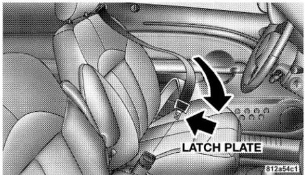
Latch Plate
34 THINGS TO KNOW BEFORE STARTING YOUR VEHICLE
- When the belt is long enough to fit, insert the latch plate into the buckle until you hear a "click."
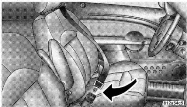
natural_image
Interior view of a car showing the seatbelt and dashboard (no text or symbols visible)Latch Plate To Buckle
WARNING!
- A belt that is buckled into the wrong buckle will not protect you properly. The lap portion could ride too high on your body, possibly causing internal injuries. Always buckle your belt into the buckle nearest you.
- A belt that is too loose will not protect you as well. In a sudden stop you could move too far forward, increasing the possibility of injury. Wear your seat belt snugly.
- A belt that is worn under your arm is very dangerous. Your body could strike the inside surfaces of the vehicle in a collision, increasing head and neck injury. A belt worn under the arm can cause internal injuries. Ribs aren't as strong as shoulder bones. Wear the belt over your shoulder so that your strongest bones will take the force in a collision.
-
A shoulder belt placed behind you will not protect you from injury during a collision. You are more likely to hit your head in a collision if you do not wear your shoulder belt. The lap and shoulder belt are meant to be used together.
-
Position the lap belt across your thighs, below your abdomen. To remove slack in the lap belt portion, pull up on the shoulder belt. To loosen the lap belt if it is too tight, tilt the latch plate and pull on the lap belt. A snug belt reduces the risk of sliding under the belt in a collision.
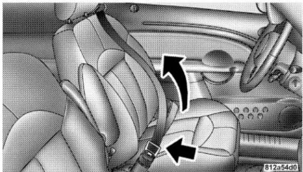
natural_image
Interior view of a car showing seatbelt and steering wheel (no text or symbols visible)Removing Slack From Belt
WARNING!
- A lap belt worn too high can increase the risk of internal injury in a collision. The belt forces won't be at the strong hip and pelvic bones, but across your abdomen. Always wear the lap belt as low as possible and keep it snug.
- A twisted belt can't do its job as well. In a collision it could even cut into you. Be sure the belt is straight. If you can't straighten a belt in your vehicle, take it to your dealer and have it fixed.
- Position the shoulder belt on your chest so that it is comfortable and not resting on your neck. The retractor will withdraw any slack in the belt.
36 THINGS TO KNOW BEFORE STARTING YOUR VEHICLE
- To release the belt, push the red button on the buckle. The belt will automatically retract to its stowed position. If necessary, slide the latch plate down the webbing to allow the belt to retract fully.
WARNING!
A frayed or torn belt could rip apart in a collision and leave you with no protection. Inspect the belt system periodically, checking for cuts, frays, or loose parts. Damaged parts must be replaced immediately. Do not disassemble or modify the system. Seat belt assemblies must be replaced after a collision if they have been damaged (bent retractor, torn webbing, etc.).
Seat Belt Webbing Guide
NOTE: The manufacturer recommends that the seat belt is routed through the seat belt webbing guide when using the seatbelt.
The seat belt webbing guide should be used to improve seat belt accessibility. The seat belt can be removed from the guide to allow for easier access to the rear seats.
THINGS TO KNOW BEFORE STARTING YOUR VEHICLE 37
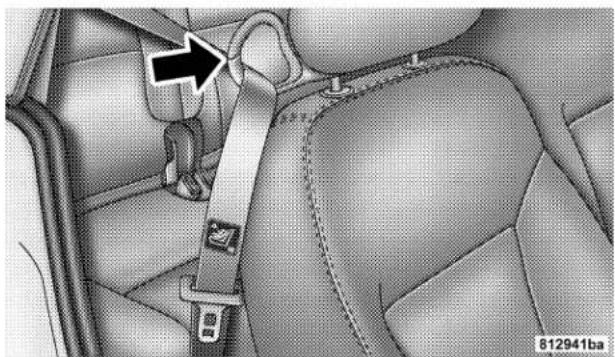
natural_image
Interior view of a car showing the seatbelt and dashboard compartment with a black arrow pointing to a specific area (no text or symbols present)Seat Belt Webbing Guide
Lap/Shoulder Belt Untwisting Procedure
Use the following procedure to untwist a twisted lap/shoulder belt.
- Position the latch plate as close as possible to the anchor point.
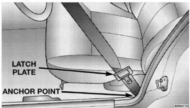
Positioning Latch Plate
38 THINGS TO KNOW BEFORE STARTING YOUR VEHICLE
- At about 6 to 12 inches (15 to 30 cm) above the latch plate, grasp and twist the belt webbing 180^ to create a fold that begins immediately above the latch plate.
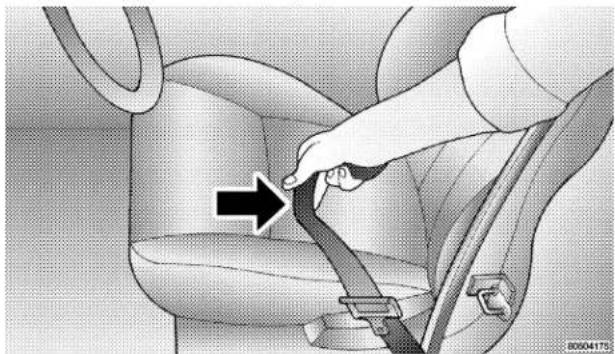
natural_image
Car seatbelt buckle being lifted, showing hand placement and arrow indicating direction (no text or symbols)Creating A Fold Sliding The Latch Plate
- Slide the latch plate upward over the folded webbing. The folded webbing must enter the slot at the top of the latch plate.
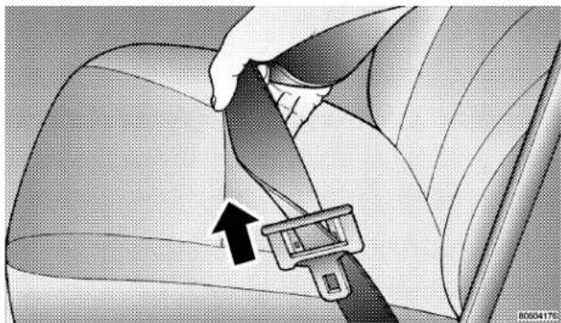
natural_image
Car seatbelt buckle being adjusted for a hand (no text or symbols visible)- Continue to slide the latch plate up until it clears the folded webbing.
Seat Belt Pretensioners
The seat belts for both front seating positions are equipped with pretensioning devices that are designed to remove slack from the seat belt in the event of a collision. These devices improve the performance of the seat belt by assuring that the belt is tight about the occupant early in a collision. Pretensioners work for all size occupants, including those in child restraints.
NOTE: These devices are not a substitute for proper seat belt placement by the occupant. The seat belt still must be worn snugly and positioned properly.
The pretensioners are triggered by the front airbag control module (see Airbag Section). Like the front airbags, the pretensioners are single use items. After a collision that is severe enough to deploy the airbags and pretensioners, both must be replaced.
Seat Belts And Pregnant Women
We recommend that pregnant women use the seat belts throughout their pregnancy. Keeping the mother safe is the best way to keep the baby safe.
Pregnant women should wear the lap part of the belt across the thighs and as snug across the hips as possible. Keep the belt low so that it does not come across the abdomen. That way the strong bones of the hips will take the force if there is a collision.
40 THINGS TO KNOW BEFORE STARTING YOUR VEHICLE
Driver and Front Passenger Supplemental Restraint System (SRS) - Airbag
This vehicle has airbags for both the driver and front passenger as a supplement to the seat belt restraint systems. The driver's front airbag is mounted in the center of the steering wheel. The passenger's front airbag is mounted in the instrument panel, above the glove compartment. The words SRS AIRBAG are embossed on the airbag covers.
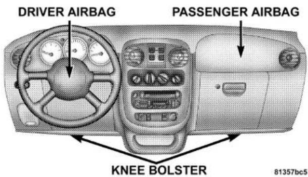
Front Airbag Components
NOTE: The front airbags are certified to the Federal regulations that allow less forceful deployment.
If the vehicle is equipped with side airbags, they are located inside the driver and front passenger seats, and their covers are also labeled SRS AIRBAG.
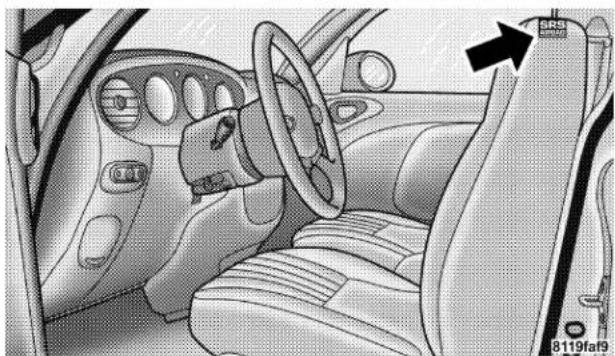
natural_image
Interior view of a car dashboard and steering wheel (no visible text or symbols)Side Airbags
WARNING!
- Do not put anything on or around the airbag covers or attempt to manually open them. You may damage the airbags and you could be injured because the airbags are not there to protect you. These protective covers for the airbag cushions are designed to open only when the airbags are inflating.
- If your vehicle is equipped with side airbags, do not use accessory seat covers or place objects between you and the side airbags; the performance could be adversely affected and/or objects could be pushed into you, causing serious injury.
- If your vehicle is equipped with side airbags, do not attach cup holders or any other objects on or around the door. The inflating side airbag could drive the object into occupants, causing serious injury.
42 THINGS TO KNOW BEFORE STARTING YOUR VEHICLE
Airbags inflate in moderate to high speed impacts. Along with seat belts and pretensioners, front airbags work with the instrument panel knee bolsters to provide improved protection for the driver and front passenger. Side airbags also work with seat belts to improve occupant protection.
The seat belts are designed to protect you in many types of collisions. The front airbags deploy in moderate to severe frontal collisions. If your vehicle is equipped, the side airbag on the crash side of the vehicle is triggered in moderate to severe side collisions. In certain types of collisions, both the front and side airbags may be triggered. But even in collisions where the airbags work, you need the seat belts to keep you in the right position for the airbags to protect you properly.
Here are some simple steps you can take to minimize the risk of harm from a deploying airbag.
- Children 12 years old and under should always ride buckled up in a rear seat.
Infants in rear facing child restraints should NEVER ride in the front seat of a vehicle with a passenger front airbag. An airbag deployment can cause severe injury or death to infants in that position.
Children that are not big enough to properly wear the vehicle seat belt (see Section on Child Restraints) should be secured in the rear seat in child restraints or belt-positioning booster seats. Older children who do not use child restraints or belt-positioning booster seats should ride properly buckled up in the rear seat. Never allow children to slide the shoulder belt behind them or under their arm.
If a child from 1 to 12 years old must ride in the front passenger seat because the vehicle is crowded, move the seat as far back as possible, and use the proper child restraint. Refer to the section on Child Restraint.
You should read the instructions provided with your child restraint to make sure that you are using it properly.
- All occupants should wear their lap and shoulder belts properly.
- The driver and front passenger seats should be moved back as far as practical to allow the front airbags room to inflate.
- If your vehicle has side airbags, do not lean against the door, airbags will inflate forcefully into the space between you and the door.
WARNING!
- Relying on the airbags alone could lead to more severe injuries in a collision. The airbags work with your seat belt to restrain you properly. In some collisions the airbags won't deploy at all. Always wear your seat belts even though you have airbags.
- Being too close to the steering wheel or instrument panel during front airbag deployment could cause serious injury. Airbags need room to inflate. Sit back, comfortably extending your arms to reach the steering wheel or instrument panel.
- If the vehicle has side airbags, they also need room to inflate. Do not lean against the door. Sit upright in the center of the seat.
44 THINGS TO KNOW BEFORE STARTING YOUR VEHICLE
The front airbag system consists of the following:
• Airbag Control Module (ACM)
• AIRBAG Readiness Light
- Driver and Passenger Front Airbag/Inflator Units
- Unique Steering Wheel and Column
- Unique Instrument Panel
• Interconnecting Wiring
- Seat Belt Pretensioners
- Knee Impact Bolster
The Side Airbag System, on vehicles equipped, consists of the following:
- AIRBAG Readiness Light (shared with the front airbag system)
-
Side Airbag in the driver's seat
-
Side Airbag in the passenger's seat
- Airbag Control Module (shared with the front airbag system)
- Side impact sensors
• Interconnecting Wiring
How The Front Airbag System Works
- The airbag control module determines if a frontal impact is severe enough to require the airbags to inflate. The control module will not detect, roll over, or rear collisions. The airbag control module will only detect side collisions if the vehicle is so equipped with side airbags.
The airbag control module also monitors the readiness of the electronic parts of the system whenever the ignition switch is in the START or ON positions. These include all of the items listed above except the knee
bolster, instrument panel and the steering wheel and column. If the key is in the OFF position, in the ACC position, or not in the ignition switch, the airbags are not on and will not inflate.
AIR BAG
The airbag control module also turns on the AIRBAG light in the instrument panel for 6 to 8 seconds when the ignition switch is first turned ON, then turns the light off. If the front or side airbag control modules detect a malfunction in any part of the system, the airbag light will turn on either momentarily or continuously.
WARNING!
Ignoring the AIRBAG light in your instrument panel could mean you won't have the airbags to protect you in a collision. If the light does not come on, stays on after you start the vehicle, or if it comes on as you drive, have the airbag system checked right away.
- When the airbag control module detects a collision requiring the front airbags, it signals the inflator units. A large quantity of nontoxic gas is generated to inflate the front airbags. The front airbag covers separate and fold out of the way as the front airbags inflate to their full size. The front airbags fully inflate in about 50 milliseconds. This is only about half of the time it takes you to blink your eyes. The front airbags then quickly deflate while helping to restrain the driver and front passenger. The driver's front airbag gas is vented through the airbag material towards the instrument
panel. The passenger's front airbag gas is vented through vent holes in the sides of the airbag. In this way the front airbags do not interfere with your control of the vehicle.
- The Knee Impact Bolsters help protect the knees and position you for the best interaction with the front airbags.
Side Airbags Supplemental Restraint System (SRS)—If Equipped
If so equipped, the airbag control module determines if a side collision is severe enough to require the side airbags to inflate. The airbag control module will not detect roll over, front or rear collisions.
The Airbag Control Module monitors the readiness of the electronic parts of the system whenever the ignition switch is in the START or ON positions. These include all of the items listed under "The Side Airbag System", on vehicles equipped, consists of the following". In moderate to severe side collisions, the side airbag inflator on the crash side of the vehicle is triggered, releasing a quantity of nontoxic gas. The inflating side airbag exits through the seat seam into the space between the occupant and the door. The side airbag moves at a very high speed and with such a high force, that it could injure you if you are not seated properly, or if items are positioned in the area where the side airbag inflates. This especially applies to children.
If A Deployment Occurs
The airbag systems are designed to deploy when the airbag control module detects a moderate-to-severe collision, to help restrain the driver and front passenger, and then immediately deflate.
NOTE: A collision that is not severe enough to need airbag protection will not activate the system. This does not mean something is wrong with the airbag system.
If you do have a collision which deploys the airbags, any or all of the following may occur:
- The nylon airbag material may sometimes cause abrasions and/or skin reddening to the driver and front passenger as the airbags deploy and unfold. The abrasions are similar to friction rope burns or those you might get sliding along a carpet or gymnasium floor. They are not caused by contact with chemicals. They are not permanent and normally heal quickly. However, if you haven't healed significantly within a few days, or if you have any blistering, see your doctor immediately.
- As the airbags deflate you may see some smoke-like particles. The particles are a normal by-product of the process that generates the nontoxic gas used for airbag inflation. These airborne particles may irritate the skin, eyes, nose, or throat. If you have skin or eye irritation, rinse the area with cool water. For nose or throat
irritation, move to fresh air. If the irritation continues, see your doctor. If these particles settle on your clothing, follow the garment manufacturer's instructions for cleaning.
- It is not advisable to drive your vehicle after the airbags have deployed. If you are involved in another collision, the airbags and seat belt pretensioners will not be in place to protect you.
WARNING!
Deployed airbags and seat belt pretensioners cannot protect you in another collision. Have the airbags and seat belt pretensioners replaced by an authorized dealer as soon as possible.
Maintaining Your Airbag System
WARNING!
- Modifications to any part of the airbag system could cause it to fail when you need it. You could be injured because the airbags are not there to protect you. Do not modify the components or wiring, including adding any kind of badges or stickers to the steering wheel hub trim cover or the upper right side of the instrument panel. Do not modify the front bumper, vehicle body structure, or frame.
- You need proper knee impact protection in a collision. Do not mount or locate any aftermarket equipment on or behind the knee bolsters.
- It is dangerous to try to repair any part of the airbag system yourself. Be sure to tell anyone who works on your vehicle that it has airbags.
Airbag Light
You will want to have the airbags ready to inflate for your protection in a collision. While the airbag system is designed to be maintenance free, if any of the following occurs, have an authorized dealer service the system immediately.
- The AIRBAG light does not come on or flickers during the 6 to 8 seconds when the ignition switch is first turned on.
- The light remains on or flickers after the 6 to 8 second interval.
- The light flickers or comes on and remains on while driving.
Child Restraint
Everyone in your vehicle needs to be buckled up at all times — babies and children, too. Every state in the United States and all Canadian provinces require that small children ride in proper restraint systems. This is the law, and you can be prosecuted for ignoring it.
Children 12 years and under should ride properly buckled up in a rear seat, if available. According to crash statistics, children are safer when properly restrained in the rear seats, rather than in the front.
WARNING!
In a collision, an unrestrained child, even a tiny baby, can become a missile inside the vehicle. The force required to hold even an infant on your lap could become so great that you could not hold the child, no matter how strong you are. The child and others could be badly injured. Any child riding in your vehicle should be in a proper restraint for the child's size.
Infants And Small Children
There are different sizes and types of restraints for children from newborn size to the child almost large enough for an adult safety belt. Always check the child seat owner's manual to ensure you have the correct seat for your child. Use the restraint that is correct for your child:
- Safety experts recommend that children ride rearward-facing in the vehicle until they are at least one year old and weigh at least 20 lbs (9 kg). Two types of child restraints can be used rearward-facing: infant carriers and "convertible" child seats. Both types of child restraints are held in the vehicle by the lap/shoulder belt or the LATCH child restraint anchorage system.
- The infant carrier is only used rearward-facing in the vehicle. It is recommended for children who weigh up to about 20 lbs (9 kg). "Convertible" child seats can be
used either rearward-facing or forward-facing in the vehicle. Convertible child seats often have a higher weight limit in the rearward-facing direction than infant carriers do, so they can be used rearward-facing by children who weigh more than 9 kg (20 lbs) but are less than one year old.
- Rearward-facing child seats must NEVER be used in the front seat of a vehicle with a front passenger airbag. An airbag deployment could cause severe injury or death to infants in this position.
- Children who weigh more than 20 lbs (9 kg) and who are older than one year can ride forward-facing in the vehicle. Forward-facing child seats and convertible child seats used in the forward-facing direction are for children who weigh 20 to 40 lbs (9 to 18 kg) and who are older than one year. These child seats are also held in the vehicle by the lap/shoulder belt or the LATCH child restraint anchorage system.
- The belt-positioning booster seat is for children weighing more than 40 lbs (18 kg), but who are still too small to fit the vehicle's seat belts properly. If the child cannot sit with knees bent over the vehicle's cushion while the child's back is against the seat back; they should use a Belt Positioning Booster Seat. The child and booster seat are held in the vehicle by the lap/shoulder belt. (Some booster seats are equipped with a front shield and are held in the vehicle by the lap portion.)
NOTE: For additional information refer to www.nhtsa-dot.gov or www.seatchec.org.
WARNING!
- Improper installation can lead to failure of an infant or child restraint. It could come loose in a collision. The child could be badly injured or killed. Follow the manufacturer's directions exactly when installing an infant or child restraint.
- A rearward facing child restraint should only be used in a rear seat. A rearward facing child restraint in the front seat may be struck by a deploying passenger airbag which may cause severe or fatal injury to the infant.
Here are some tips on getting the most out of your child restraint:
- Before buying any restraint system, make sure that it has a label certifying that it meets all applicable Safety Standards. We also recommend that you make sure
52 THINGS TO KNOW BEFORE STARTING YOUR VEHICLE
that you can install the child restraint in the vehicle where you will use it, before you buy it.
- The restraint must be appropriate for your child's weight and height. Check the label on the restraint for weight and height limits.
- Carefully follow the instructions that come with the restraint. If you install the restraint improperly, it may not work when you need it.
The passenger seat belts are equipped with switchable seat belt retractors, which are designed to keep the lap portion tight around the child restraint so that it is not necessary to use a locking clip.
Pull the belt from the retractor until there is enough to allow you to pass through the child restraint and slide the latch plate into the buckle. Then pull on the belt until it is all removed from the retractor. Allow the belt to return into the retractor, as the belt retracts, you will hear a clicking sound. This indicates that the seat belt is now in the automatic locking mode. Pull on the excess webbing to tighten the lap portion about the child restraint. Follow the instructions of the child restraint manufacture.
NOTE: To reset this feature you must let all of the belt webbing return into the retractor. You will not be able to pull out more webbing until all of the webbing has been returned back into the retractor.
- In the rear seat, you may have trouble tightening the lap/shoulder belt on the child restraint because the buckle or latch plate is too close to the belt path opening on the restraint. Disconnect the latch plate from the buckle and twist the short buckle end of the belt several times to shorten it. Insert the latch plate into the buckle with the release button facing out.
- If the belt still can't be tightened, or if by pulling and pushing on the restraint loosens the belt, disconnect the latch plate from the buckle, turn the buckle
THINGS TO KNOW BEFORE STARTING YOUR VEHICLE 53
around, and insert the latch plate into the buckle again. If you still can't make the child restraint secure, try a different seating position.
- Buckle the child into the seat according to the child restraint manufacturer's directions.
- When your child restraint is not in use, secure it in the vehicle with the seat belt or remove it from the vehicle. Don't leave it loose in the vehicle. In a sudden stop or collision, it could strike the occupants or seat backs and cause serious personal injury.
Lower Anchors and Tether for CHildren (LATCH)
Your vehicle is equipped with the child restraint anchorage system called LATCH, which stands for Lower Anchors and Tether for CHildren. The LATCH system provides for the installation of the child restraint without using the vehicle seat belt. Both rear seating positions have exclusive lower anchorages located at the rear of the seat cushion. They are round bars, part of the seat and body structure, and are readily visible. In addition, there are two tether strap anchorages located behind the rear seat head form, in the convertible top storage area.
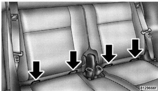
natural_image
Interior view of a car seat with three black arrows pointing to seat compartments (no text or symbols)Latch Anchors
Child restraints systems having attachments designed to connect to the lower anchorages are now available. Child restraints having tether straps and hooks for connection
to the top tether anchorage have been available for some time. In fact, many child restraint manufacturers will provide add-on tether strap kits for some of their older products. Tether anchorage kits are also available for most older vehicles.
Because the lower anchorages are to be introduced to passenger carrying vehicles over a period of years, child restraint systems having attachments for those anchorages will continue to have features for installation in vehicles using the lap or lap/shoulder belt. They will also have tether straps, and you are urged to take advantage of all of the available attachments provided with your child restraint in any vehicle.
Installing the Child Restraint System
We urge that you carefully follow the directions of the manufacturer when installing your child restraint. Many, but not all, restraint systems will be equipped with separate straps on each side, with each having a hook or connector and a means for adjusting the tension in the strap. Forward-facing toddler restraints and some rearward-facing infant restraints will also be equipped with a tether strap with a hook and means for adjusting the tension in the strap.
In general, you will first loosen the adjusters on the lower and tether straps so that you can more easily attach the hook or connector to the lower and tether anchorages. The tether strap should be routed over the center of the head form and attached to the tether anchor, located behind the rear seat head form, in the convertible top storage area. Then tighten all three straps as you push the child restraint rearward and downward into the seat.
NOTE: To gain access to the achorages, locate the child tether anchorage decals on the carpet behind the rear seat head forms and use a small screwdriver to pry the carpet flap open. The carpet flap is attached in two different places.
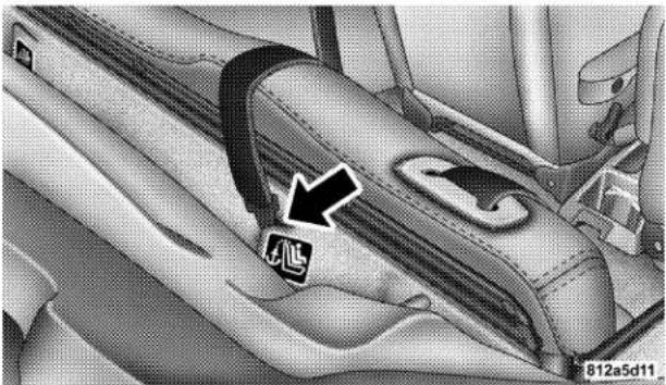
natural_image
Interior view of a car seatbelt with a black arrow pointing to the seat area (no text or symbols visible)Tether Strap Mounting
Not all child restraint systems will be installed as we have described here. Again, carefully follow the instructions that come with the child restraint system.
NOTE: If your child restraint seat is not LATCH compatible, install the restraint using the vehicle seat belts.
WARNING!
An incorrectly anchored tether strap could lead to increased head motion and possible injury to the child. Use only the anchor position directly behind the child seat to secure a child restraint top tether strap.
Children Too Large For Booster Seats
Children who are large enough to wear the shoulder belt comfortably, and whose legs are long enough to bend over the front of the seat when their back is against the seat back, should use the lap/shoulder belt in a rear seat.
• Make sure that the child is upright in the seat.
- The lap portion should be low on the hips and as snug as possible.
- Check belt fit periodically. A child's squirming or slouching can move the belt out of position.
- If the shoulder belt contacts the face or neck, move the child closer to the center of the vehicle. Never allow a child to put the shoulder belt under an arm or behind their back.
Transporting Pets
Airbags deploying in the front seat could harm your pet. An unrestrained pet will be thrown about and possibly injured, or injure a passenger during panic braking or in a collision.
Pets should be restrained in the rear seat in pet harnesses or pet carriers that are secured by seat belts.
ENGINE BREAK-IN RECOMMENDATIONS
A long break-in period is not required for the engine in your new vehicle.
Drive moderately during the first 300 miles (500 km). After the initial 60 miles (100 km), speeds up to 50 or 55 mph (80 or 90 km/h) are desirable.
While cruising, brief full-throttle acceleration, within the limits of local traffic laws, contributes to a good break-in. Wide open throttle acceleration in low gear can be detrimental and should be avoided.
The engine oil installed in the engine at the factory is a high quality energy conserving type lubricant. Oil changes should be consistent with anticipated climate conditions under which vehicle operations will occur. The recommended viscosity and quality grades are shown in Section 7 of this manual. NON-DETERGENT OR STRAIGHT MINERAL OILS MUST NEVER BE USED.
A new engine may consume some oil during its first few thousand miles (kilometers) of operation. This should be considered as a normal part of the break-in and not interpreted as an indication of difficulty.
SAFETY TIPS
Exhaust Gas
WARNING!
Exhaust gases can injure or kill. They contain carbon monoxide (CO) which is colorless and odorless. Breathing it can make you unconscious and can eventually poison you. To avoid breathing (CO) follow the safety tips below.
Do not run the engine in a closed garage or in confined areas any longer than needed to move your vehicle in or out of the area.
If it is necessary to sit in a parked vehicle with the engine running, adjust your heating or cooling controls to force outside air into the vehicle. Set the blower at high speed.
WARNING!
If you are required to drive with the deck lid/liftgate open, make sure that all windows are closed, and the climate control blower switch is set at high speed. DO NOT use the recirculation mode.
Safety Checks You Should Make Inside The Vehicle
Seat Belts
Inspect the belt system periodically, checking for cuts, frays and loose parts. Damaged parts must be replaced immediately. Do not disassemble or modify the system.
58 THINGS TO KNOW BEFORE STARTING YOUR VEHICLE
Front seat belt assemblies must be replaced after a collision. Rear seat belt assemblies must be replaced after a collision if they have been damaged (bent retractor, torn webbing, etc. If there is any question regarding belt or retractor condition, replace the belt.
Airbag Light
The light should come on and remain on for 6 to 8 seconds as a bulb check when the ignition switch is first turned ON. If the LED is not lit during starting, have it checked. If the light stays on or comes on while driving, have the system checked by an authorized dealer.
Defroster
Check operation by selecting the defrost mode and place the blower control on high speed. You should be able to feel the air directed against the windshield.
Periodic Safety Checks You Should Make Outside The Vehicle
Tires
Examine tires for excessive tread wear or uneven wear patterns. Check for stones, nails, glass, or other objects lodged in the tread. Inspect tread and sidewall for cuts or cracks. Check wheel nuts for tightness, and tires (including spare) for proper pressure.
Lights
Have someone observe the operation of exterior lights while you work the controls. Check turn signal and high beam indicator lights on the instrument panel.
Fluid Leaks
Check area under vehicle after overnight parking for fuel, engine coolant, oil or other fluid leaks. Also, if gasoline fumes are detected or fuel, power steering fluid or brake fluid leaks are suspected, the cause should be located and corrected immediately.
UNDERSTANDING THE FEATURES OF YOUR VEHICLE
CONTENTS
■Convertible Top Operation....6 2
□To Lower The Top....62
□To Raise The Top....6 6
□Convertible Top Boot Cover Installation-If Equipped....68
□Convertible Top Boot Cover Removal And Storage....7 2
□Convertible Top Manual Override....73
■Mirrors....75
□Inside Compass/Temperature Mirror ..... 7 5
□ Outside Mirror—Driver's Side .....78
□ Outside Mirror—Passenger's Side .....78
□Electric Remote-Control Mirrors....79
□Illuminated Vanity Mirrors....80
■Seats 80
□ Front Seat Adjustment .....80
□Driver's Power Seat Height Adjuster — If Equipped 81
□Reclining Bucket Seats....82
60 UNDERSTANDING THE FEATURES OF YOUR VEHICLE
□ Driver's Seat Back Tilt .....82
□Passenger Seat Back Tilt (Easy Entry System) . . .83
□Adjustable Head Restraints....85
□Heated Seats — If Equipped . . . . . . . . . . . . . . 8 6
□Folding Rear Seat....87
□Tumbling Rear Seat....8 8
■To Open And Close The Hood ..... 9 3
■Lights....94
□Interior Lights 94
□Multi-Function Control Lever....95
□Headlights, Parking Lights, Instrument Panel Lights....96
□Daytime Running Lights (Canada Only) ..... 9 6
□Lights-On Reminder....96
□Fog Lights 97
□Turn Signals 97
□Highbeam/Lowbeam Select Switch ..... 9 7
□Passing Light 97
■ Windshield Wipers And Washers .....98
□Windshield Washers....98
□Mist Feature....98
□Windshield Wiper Operation .....99
□ Intermittent Wiper System .....99
□ Adding Washer Fluid ....100
■ Tilt Steering Column .....101
■ Traction Control Switch — If Equipped .....102
Electronic Speed Control 103
□To Activate....103
□To Set At A Desired Speed....104
□To Deactivate....104
□To Resume Speed....104
□To Vary The Speed Setting....104
□Manual Transaxle....105
□To Accelerate For Passing....105
■ Garage Door Opener — If Equipped .....106
□Programming The Universal Transceiver....107
□ "Rolling Code" Programming .....109
UNDERSTANDING THE FEATURES OF YOUR VEHICLE
☐Canadian Programming/Gate Programming .. 110
□Operation....1 1 1
□Reprogramming A Single Button....1 1 1
□Security 11
■ Electrical Power Outlets .....112
□ Electrical Outlet Use With Engine Off .....114
■ Console Features ....115
■ Storage .....116
□ Front Seat Storage Bin .....116
□Storage Pockets....117
CONVERTIBLE TOP OPERATION
WARNING!
The convertible top does not provide the structural protection that a reinforced metal roof does, and the fabric top cannot be expected to prevent the ejection of the occupants of a vehicle in a collision. Therefore it is important that all occupants wear their seat belts at all times when riding in a convertible. Studies have shown that it is generally safer to remain inside a vehicle during a collision, than to be ejected from the vehicle.
To Lower The Top:
NOTE: Thoroughly dry the convertible top and top storage area, prior to leaving the top lowered for an extended period of time. This will help prevent possible mildew build-up.
CAUTION!
To avoid damage to the convertible top or its components, your vehicle is equipped with a feature that prevents convertible top operation at speeds over 10 mph (16 km/h).
CAUTION!
To fully insure that no damage occurs, be sure that the vehicle is at a complete stop with the gear selector in the Park position (automatic transaxle) or in the Neutral position (manual transaxle) before lowering or raising the top.
CAUTION!
To avoid damage to either the top or the rear window, check the top storage area at the rear of the vehicle interior to be sure that it is clear of debris or other items. Be sure that child seat flip up bars are lowered. Do not use the top storage area for other storage purposes.
CAUTION!
Do not operate the convertible top with ice or snow build-up on the top. Damage to the top may occur.
64 UNDERSTANDING THE FEATURES OF YOUR VEHICLE
- Turn the ignition key to the ON position.
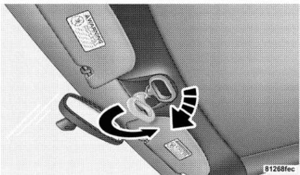
- Release the top from the windshield header by pulling down on the latch handle and turning the latch handle clockwise until it stops.
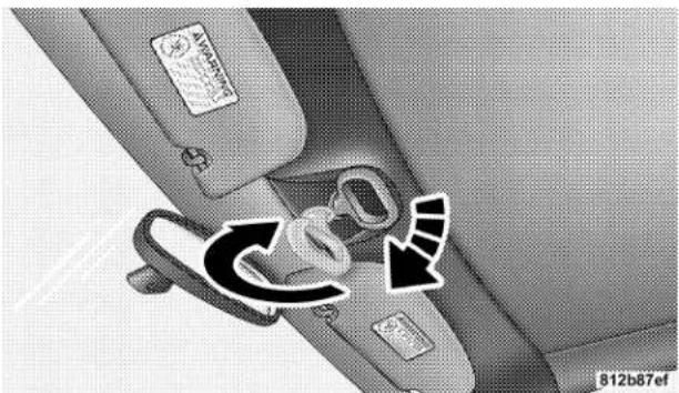
natural_image
Interior view of a car seatbelt with directional arrows indicating movement or change (no text or symbols)Releasing Convertible Top Latches
- Press the Power Top Switch to disengage the top pins from the header, turn the handle counterclockwise and raise the handle to the stowed position.
NOTE: The Power Top Switch has two detent positions for lowering the convertible top. Pressing and holding the Power Top Switch lightly in the first detent position will lower the windows slightly and the convertible top to the full down position. Pressing and holding the switch in the second detent position will lower all four windows completely and the top to the full down position.
UNDERSTANDING THE FEATURES OF YOUR VEHICLE 65
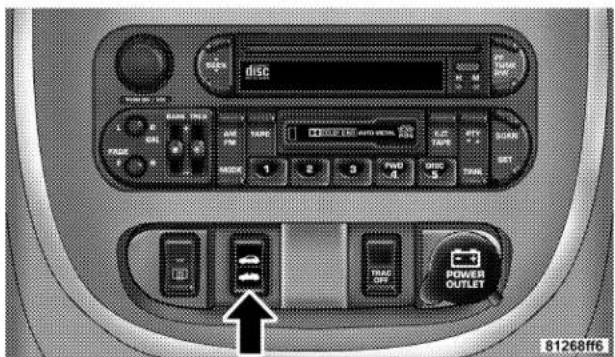
Convertible Top Switch
-
Continue pressing the Power Top Switch until the convertible top is lowered completely.
-
Install the Convertible Top Boot Cover, if equipped. Refer to Convertible Top Boot Cover Installation-If Equipped, in this section.
CAUTION!
Damage to the convertible top boot cover could result if the latch handle is not completely closed when the top is lowered. The convertible top boot cover cannot be installed while the latch handle is open.
To Raise The Top:
| CAUTION! |
| To avoid damage to the convertible top or its components, your vehicle is equipped with a feature that prevents convertible top operation at speeds over 10 mph (16 km/h). |
| CAUTION! |
| To fully insure that no damage occurs, be sure that the vehicle is at a complete stop with the gear selector in the Park position (automatic transaxle) or in the Neutral position (manual transaxle) before lowering or raising the top. |
- Remove the convertible top boot cover, if equipped. Refer to Convertible Top Boot Cover Removal and Storage, in this section.
- Turn the ignition to the ON position.
- Press the Power Top Switch to raise the top. Before the top reaches the windshield, open the latch handle and turn the handle clockwise to open the latches. Press the switch again to continue raising the top until the two pins seat themselves in the windshield header.
NOTE: If the top is not latched right away, it may be necessary to press the power top switch, "UP" or "DOWN" quickly, to align the pins to the windshield header.
- Pull down on the latch handle and rotate it counterclockwise to engage the latches.
UNDERSTANDING THE FEATURES OF YOUR VEHICLE 67
natural_image
Interior view of a car seatbelt with directional arrows indicating movement or change (no text or symbols)CAUTION!
Car top carriers, ski racks, etc., should not be attached to the convertible top mechanism as they will damage the top. Do not place objects on the convertible top, in the top well or on the sport bar. Damage to the convertible top may occur.
Engaging Convertible Top Latches
- Raise the latch handle into the stowed position.
68 UNDERSTANDING THE FEATURES OF YOUR VEHICLE
Convertible Top Boot Cover Installation-If Equipped
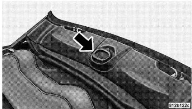
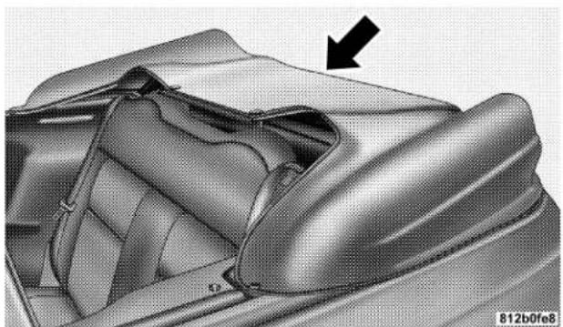
- With the top down and the convertible top latch handle in the stowed position, lay the unfolded boot cover across the convertible top.
natural_image
Close-up of a fabric or leather piece with a black arrow pointing to a circular opening, no visible text or symbols.Convertible Top Latch Handle
natural_image
Interior view of a car showing seatbelt and dashboard (no text or symbols visible)Boot Laying Across Convertible Top
UNDERSTANDING THE FEATURES OF YOUR VEHICLE 69
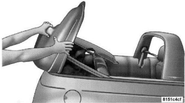
- Install the rear edge of the boot, first tucking the rear edge of the boot under the rear and both sides of the rails.
natural_image
Person opening a car into the windshield, viewed from inside (no text or symbols visible)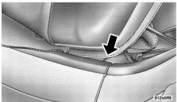
natural_image
Close-up of a car interior showing a curved seat and dashboard, with a black arrow pointing to a specific area (no text or symbols present)Tucking Boot Under Rail
70 UNDERSTANDING THE FEATURES OF YOUR VEHICLE
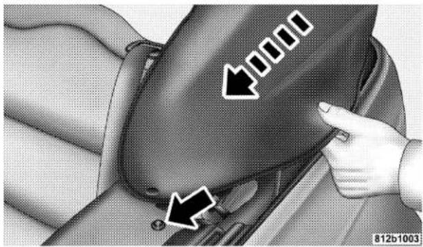
- Pull the right and left boot arms forward and engage both boot arm snaps. Make sure both snaps are fully engaged.
natural_image
Interior view of a car seatbelt with arrows indicating movement or positioning (no text or symbols)Engaging Boot Arm Snaps
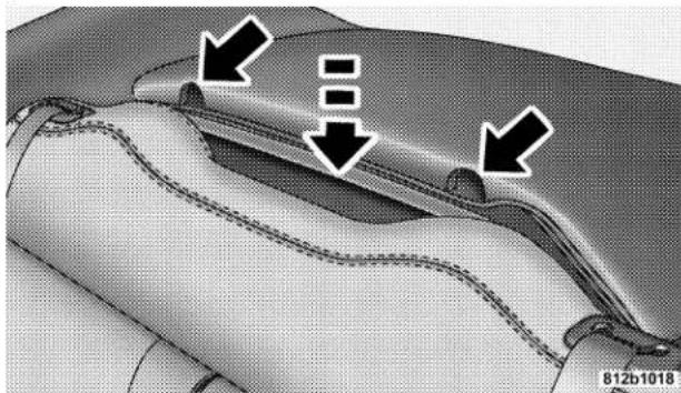
- Engage the boot center section retainer using the tabs provided.
natural_image
Close-up of a garment collar with stitching details and arrows indicating seam allowance (no text or symbols)Engaging Boot Center Section
UNDERSTANDING THE FEATURES OF YOUR VEHICLE 71
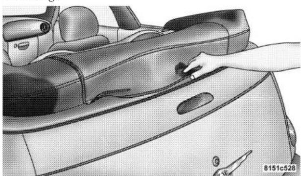
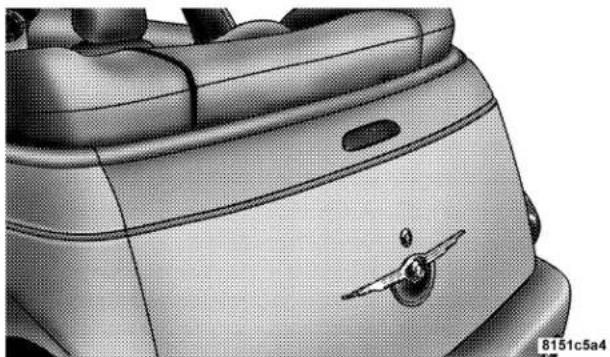
- Tuck the rear flap of the boot in behind the Upper Moulding.
natural_image
Illustration of a car interior showing a hand interacting with the lid (no text or symbols visible)Tucking In Rear Flap
natural_image
Close-up of a car's front wheel and dashboard (no visible text or symbols)72 UNDERSTANDING THE FEATURES OF YOUR VEHICLE
Convertible Top Boot Cover Removal and Storage
- Unsnap the snaps and remove the top cover boot.
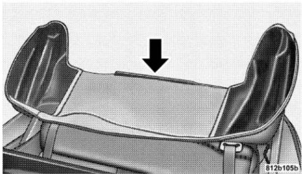
- Lay the boot cover flat with the center section retainer facing the rear of the car.
natural_image
Technical illustration of a mechanical component with a downward arrow indicating a feature (no text or symbols present)Boot Removed And Laying Flat
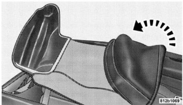
- First fold the left side of the boot cover to the middle of the boot cover.
natural_image
Mechanical component with curved surfaces and a rotation arrow indicator (no text or symbols)Folding Boot Cover Left Side
- Second fold the right side of the boot cover to the middle, fitting it inside the left side of the boot cover and store it in the trunk or a dry secure area.
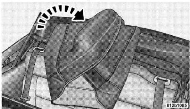
natural_image
Interior view of a car seatbelt with belt and side arm, showing no text or symbolsFolding Boot Cover Right Side
CAUTION!
Do not lay heavy objects on top of the boot or lay the boot on top of sharp/pointy objects. Damage could occur to the boot.
CONVERTIBLE TOP MANUAL OVERRIDE
If your vehicle is experiencing electrical failure (low battery, etc.) and it is necessary to raise the convertible top, perform the following steps:
- Locate the convertible top motor bleeder screw, which is found in the trunk under the convertible top storage area.
74 UNDERSTANDING THE FEATURES OF YOUR VEHICLE
- Turn the screw counterclockwise until the screw stops. This will relieve the hydraulic pressure and allow the convertible top to be raised manually.
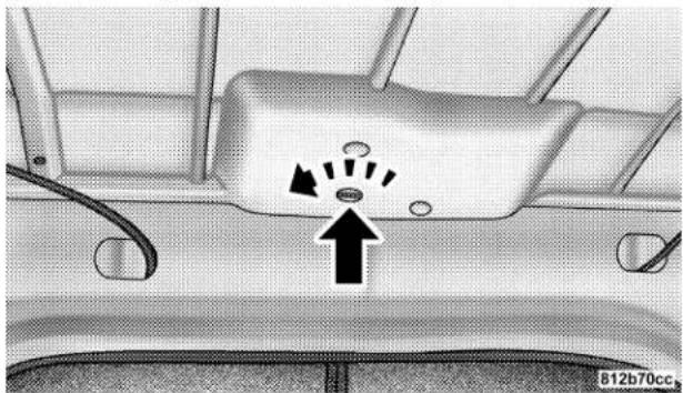
natural_image
Top-down view of a car's front bumper with directional arrows and a warning symbol (no text or labels)Bleeder Screw
-
Using the latch handle raise the top until the two pins seat themselves in the windshield header.
-
Rotate the latch handle clockwise to open the latches.
-
Pull down and rotate the handle counterclockwise to engage the latches.
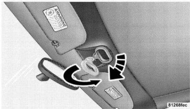
natural_image
Interior view of a car showing the seatbelt and dashboard (no text or symbols visible)Engaging Convertible Top Latches
-
Raise the handle into the stowed position.
-
Close the convertible top motor bleeder screw by turning the screw clockwise until it stops.
MIRRORS
Inside Compass/Temperature Mirror
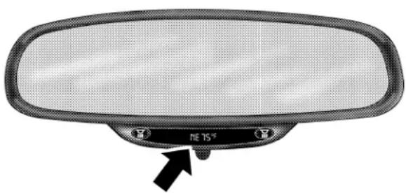
This manual day-night inside rearview mirror has an integrated compass and outside temperature display, along with dual map/courtesy lamps with switches for independent operation. These lamps also turn on together with the dome lamp.
Adjust the mirror to center the view through the rear window. A two point pivot system allows for horizontal and vertical mirror adjustments.
Annoying headlight glare can be reduced by rotating the small knob under the mirror in the clockwise direction, so the knob points to the right (night position). The mirror should be adjusted while set in the day position (knob points towards rear of vehicle.)
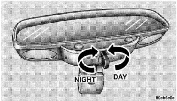
Adjusting Rear View Mirror
76 UNDERSTANDING THE FEATURES OF YOUR VEHICLE
Lights
- Briefly press the "Right" button to toggle the right reading lamp "ON/OFF". Repeat the key press to cycle the light.
- Briefly press the "Left" button to toggle the left reading lamp "ON/OFF". Repeat the key press to cycle the light.
NOTE: The light can be activated with the ignition off.
NOTE: The light(s) will automatically shut off after seven minutes with ignition off.
Temperature
Press and hold the "Right" button for 5–10 seconds (until °F/°C toggles in the display) then release the button. Repeat the key press to cycle the °F/°C in the display.
natural_image
Front view of a car rearview mirror with a black arrow pointing to the side panel (no text or symbols on the mirror itself)80c805c6
Display ON/OFF
Press and hold the "Right" button for 10–15 seconds (until display toggles ON/OFF) then release the button. Repeat the key press to cycle the display ON/OFF.
NOTE: The display will default "ON" at each new ignition cycle.
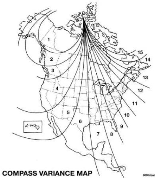
Compass Variance
- Find your current location and determine the correct Zone number from the map.
- Press and hold the "Left" button for 5–10 seconds (until "Zone" appears in the display), then release the button. The number displayed is the current Zone value.
- If a new Zone value is desired, briefly press the "Left" button to increment the displayed value, (Range 1–15) until you find your desired Zone number.
- No button activity for 4–5 seconds ends the Zone entry mode. The display will return to normal operation and the new Zone number will be set.
78 UNDERSTANDING THE FEATURES OF YOUR VEHICLE
Compass Calibration
If "CAL" is not displayed, press and hold the "Left" button for 10–15 seconds, until "CAL" appears in the display, then release the button. The compass is now in calibration mode.
The mirror can be calibrated in one of two ways
- Drive the vehicle in circles at less then 5mph (8 km/h) until "CAL" no longer appears in the display.
- Drive the vehicle under normal operating conditions.
Outside Mirror—Driver's Side
Adjust the outside mirror to center on the adjacent lane of traffic, with a slight overlap of the view obtained on the inside mirror.
Outside Mirror—Passenger's Side
Adjust the convex outside mirror so you can just see the side of your vehicle in the part of the mirror closest to the vehicle.
WARNING!
Vehicles and other objects seen in the passenger side convex mirror will look smaller and farther away than they really are. Relying too much on your passenger side mirror could cause you to collide with another vehicle or other object. Use your inside mirror when judging the size or distance of a vehicle seen in this convex mirror.
UNDERSTANDING THE FEATURES OF YOUR VEHICLE 79
Electric Remote-Control Mirrors
Use the mirror select switch, located to the left of the steering column on the instrument panel, to adjust the view obtained in the outside mirrors. Press the L or R button for Left or Right mirror selection. Use the center off position to guard against accidentally moving a mirror position.
Select a mirror and press one of the four arrows for the direction you want the mirror to move.
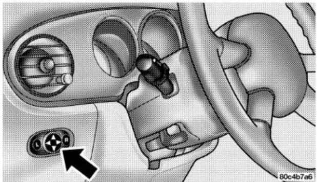
natural_image
Medical illustration of a car interior showing dashboard and ventricles with a connector (no text or symbols)Power Mirror Switches
80 UNDERSTANDING THE FEATURES OF YOUR VEHICLE
Illuminated Vanity Mirrors
An illuminated vanity mirror is on the sun visor. To use the mirror, rotate the sun visor down and swing the mirror cover upward. The lights turn on automatically. Closing the mirror cover turns off the lights.
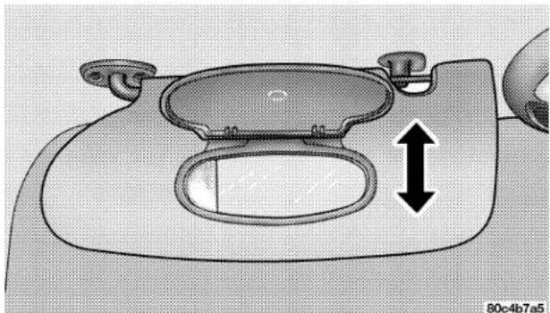
natural_image
Technical diagram of a car front bumper with a double-headed arrow indicating measurement or alignment (no text or symbols present)Illuminated Vanity Mirror
SEATS
Front Seat Adjustment
The adjusting bar is at the front of the seats, near the floor. Pull the bar up to move the seat to the desired position.
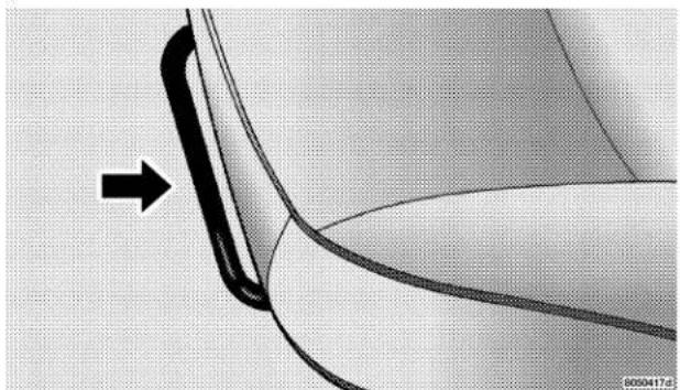
natural_image
Close-up of a curved mechanical component with an arrow indicating direction, no visible text or symbolsManual Front Seat Adjuster
Using body pressure, move forward and rearward on the seat to be sure the seat adjusters have latched.
WARNING!
- Adjusting a seat while the vehicle is moving is dangerous. The sudden movement of the seat could cause you to lose control. The seat belt might not be properly adjusted and you could be injured. Adjust the seat only while the vehicle is parked.
- Do not ride with the seatback reclined so that the shoulder belt is no longer resting against your chest. In a collision you could slide under the seat belt and be seriously or even fatally injured. Use the recliner only when the vehicle is parked.
Driver's Power Seat Height Adjuster — If Equipped
The power seat height adjuster is on the outboard side of the driver's seat. Use this switch to move the seat up or down.
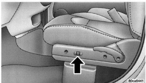
natural_image
Interior view of a car seatbelt with a black arrow pointing to the seatbelt (no text or symbols visible)Driver's Power Seat Height Adjuster
82 UNDERSTANDING THE FEATURES OF YOUR VEHICLE
Reclining Bucket Seats
The recliner control is on the outboard side of the seat. To recline, lean forward slightly before lifting the lever, then lean back to the desired position and release the lever. Lean forward and lift the lever to return the seatback to its normal position.
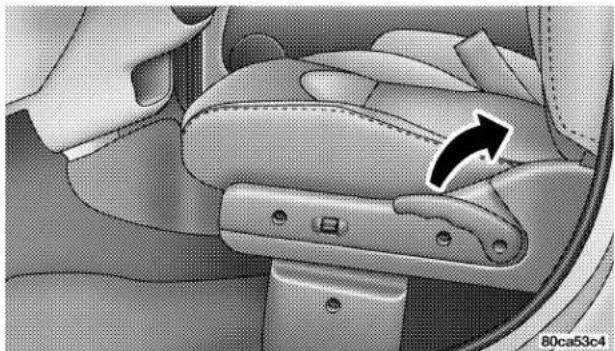
natural_image
Interior view of a car seatbelt with a directional arrow indicating rotation (no text or symbols)Recliner Control Lever
Driver's Seat Back Tilt
How to operate the driver's seat:
- Rotate front seat handle rearward until seat back releases.
- While holding the handle, push seat back forward, then let go of the handle. Continue pushing the seat back forward.
- To return seat to a sitting position, push seat back rearward.
NOTE: The driver's front seat has a full recliner memory, which will allow the seat back to return to its original position.
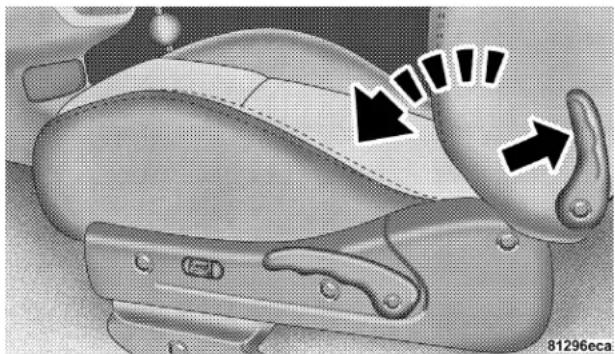
natural_image
Close-up of a car seatbelt with black arrows indicating movement or force (no text or symbols)Driver's Seat Back Tilt Handle
Passenger Seat Back Tilt (Easy Entry System)
How to operate the passenger front seat:
- Rotate front seat handle rearward until seat back releases.
- While holding the handle, push seat back forward, then let go of the handle.
84 UNDERSTANDING THE FEATURES OF YOUR VEHICLE
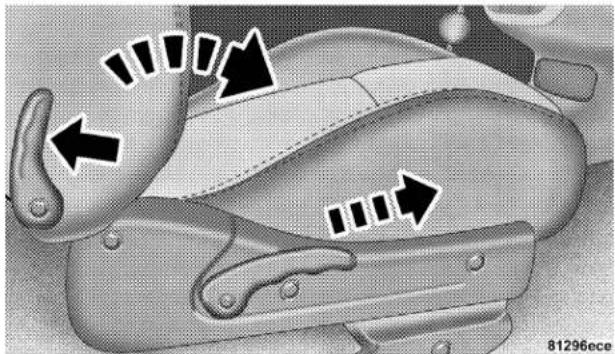
Passenger Seat Back Tilt Handle
-
Continue pushing the entire seat forward until it slides toward the dashboard.
-
To return seat to a sitting position, rotate seat back upright until it locks.
- Push seat rearward until the track locks.
NOTE: The passenger front seat has a full recliner memory, which will allow the seat back to returned to its original position.
NOTE: The passenger front seat has a mid-track memory, which returns the seat to the middle off the track regardless of original position.
UNDERSTANDING THE FEATURES OF YOUR VEHICLE 85
Adjustable Head Restraints
Head restraints can reduce the risk of whiplash injury in the event of impact from the rear. Pull up or push down on the head restraints so that the upper edge is as high as practical. To raise the head restraint, pull up on the head restraint. To lower the head restraint, depress the button and push down on the head restraint.
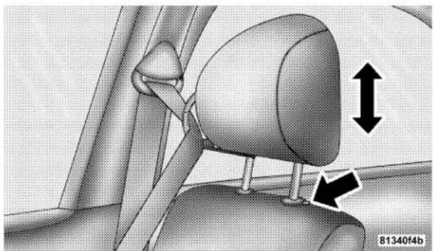
natural_image
Mechanical component diagram showing a belt drive mechanism with directional arrows (no text or symbols)Adjustable Head Restraints
86 UNDERSTANDING THE FEATURES OF YOUR VEHICLE
Heated Seats — If Equipped
This feature heats the front driver's and passenger's seats. The control for the heater is located on the outboard side of each seat. After turning on the ignition, you may choose from HIGH, or LOW heat settings. An indicator on the switch shows which setting has been chosen.
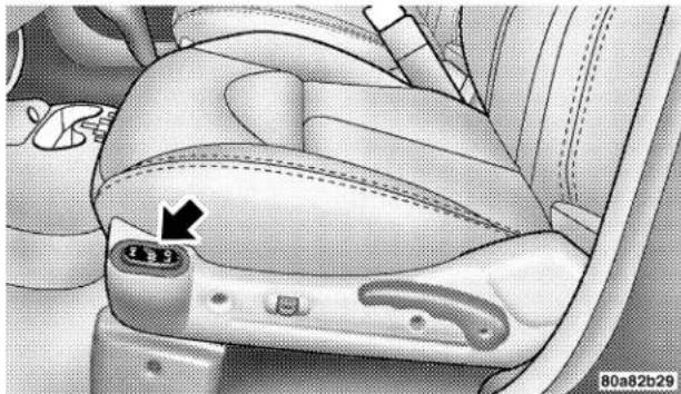
natural_image
Interior view of a car seatbelt with a black arrow pointing to the seatbelt (no text or symbols visible)Heated Seat Switch
Press the switch once to select a heat setting (high or low) and press the switch a second time in the same direction to turn the heated seat off.
NOTE: Once a heat setting is selected, heat will be felt within 2 to 3 minutes.
UNDERSTANDING THE FEATURES OF YOUR VEHICLE 87
Folding Rear Seat
To provide additional storage area, each rear seatback can be folded forward. The seat back release knobs are located in the trunk area. Pull the left side seatback release knob to fold down the left side seatback. Pull the right side seatback release knob to fold down the right side seatback.
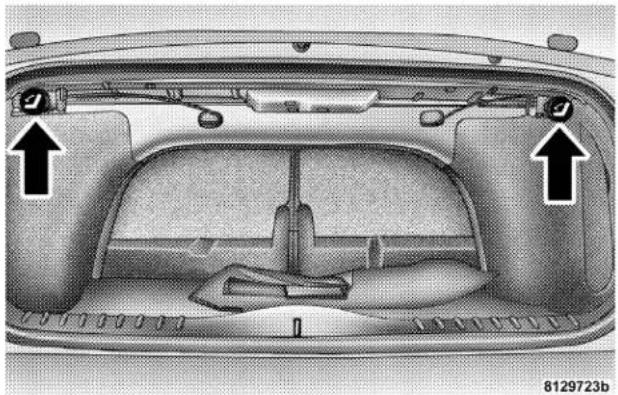
natural_image
Interior view of a car's back panel showing structural components and ventilation ducts (no text or symbols)Folding Rear Seat Release Knobs
WARNING!
- It is extremely dangerous to ride in a cargo area, inside or outside of a vehicle. In a collision, people riding in these areas are more likely to be seriously injured or killed.
- Do not allow people to ride in any area of your vehicle that is not equipped with seats and seat belts.
- Be sure that everyone in your vehicle is in a seat and using a seat belt properly.
NOTE: Prior to lifting either seatback to the upright position, be sure that the seat belt is brought forward to avoid trapping it behind the seatback.
Tumbling Rear Seat
To provide additional storage area, each rear seat can be tumbled forward.
CAUTION!
It is important that the front seats be pulled forward to the midpoint of the seat track to avoid contact between the rear seat and the front seatback. If the front seat is not pulled forward the two seats will make contact during the tumbling motion and cause damage to the rear seat material. After the rear seat is tumbled forward and secured the front seat can then be repositioned to the preferred position.
UNDERSTANDING THE FEATURES OF YOUR VEHICLE 89
To tumble the seat forward use the following procedure:
- The seat back release knobs are located in the trunk area. Pull the left side seatback release knob to fold down the left side seatback. Pull the right side seatback release knob to fold down the right side seatback.
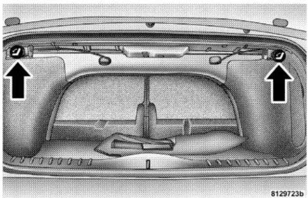
natural_image
Interior view of a car backrest with visible structural components and two arrows indicating specific parts (no text or symbols present)Folding Rear Seat Release Knobs
90 UNDERSTANDING THE FEATURES OF YOUR VEHICLE
- From inside the vehicle, fold the rear seat back down flat.
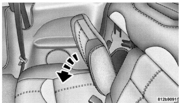
natural_image
Interior view of a car seatbelt with a black arrow pointing to the seat area (no text or symbols visible)Folding Rear Seat Back Tumbling Rear Seat
- Pull the release handle located at the bottom of the folded seat back and tumble the seat forward.
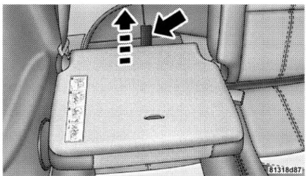
natural_image
Interior view of a car seatbelt with indicator lights and arrows pointing to the rear panel (no text or symbols visible)UNDERSTANDING THE FEATURES OF YOUR VEHICLE 91
- Attach the cinching tether strap, located at the side of the seat cushion, onto the hook bar on the center trim panel and tighten by pulling the cinching strap until the seat is secure.
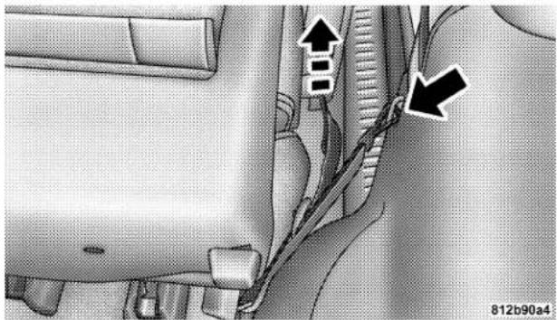
natural_image
Close-up of a car's side profile showing a zipper and cable being inserted (no text or symbols visible)Cinching Tether Strap
To return the tumbling rear seat to the latched (normal) position use the following procedure:
- Loosen the strap by pushing rearward on the cinching tether strap buckle.
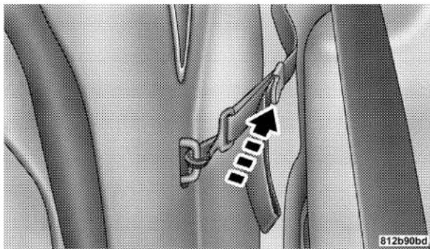
natural_image
Medical illustration showing a surgical instrument inserted into tissue, with no visible text or symbolsReleasing Cinching Tether Strap
- Disconnect the cinching tether strap.
NOTE: The strap should be reinstalled in the side pocket on the seat cushion before returning the seat to the latched (normal) position.
92 UNDERSTANDING THE FEATURES OF YOUR VEHICLE
NOTE: Prior to rotating the seat cushions reward, be sure that the rear seat belt buckles are secured with the straps, so that the buckles are accessible.
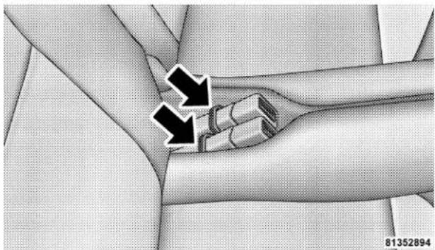
natural_image
Medical illustration showing a hand holding a joint with two arrows pointing to the joint area (no text or symbols present)Rear Seat Belt Buckle Straps
NOTE: Prior to lifting either seatback to the upright position, be sure that the seat belt is brought forward to avoid trapping it behind the seatback.
- Rotate the seat cushion rearward to latch the seat. Then lift the seatback to its upright latched position.
WARNING!
In an accident, you or others in your vehicle could be injured if seats are not properly latched to their attachments. Always be sure the seats are fully latched.
UNDERSTANDING THE FEATURES OF YOUR VEHICLE 93
TO OPEN AND CLOSE THE HOOD
To open the hood, two latches must be released. First pull the hood release lever located under the left side of the instrument panel.
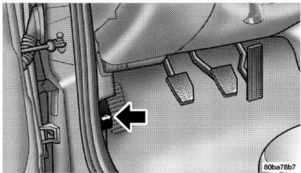
natural_image
Mechanical component diagram showing a lever mechanism with a black arrow pointing to a specific part (no text or symbols present)Hood Release Lever
Then move the safety catch located under the front edge of the hood, near the center and slightly to the right, and raise the hood.
Use the hood prop rod clipped to the driver's side of the engine compartment to secure the hood in the open position. Place the hood prop at the location stamped into the inner hood surface.
To prevent possible damage, do not slam the hood to close it. Lower the hood until it is open approximately 20 cm (8 inches) and then drop it. This should secure both latches. Never drive your vehicle unless the hood is fully closed, with both latches engaged.
94 UNDERSTANDING THE FEATURES OF YOUR VEHICLE
WARNING!
If the hood is not fully latched it could fly up when the vehicle is moving and block your forward vision. You could have a collision. Be sure all hood latches are fully latched before driving.
LIGHTS
Interior Lights
The interior lights come on when a door or the deck lid is opened.
With the ignition key in the OFF position, the interior lights will automatically turn off in about 8 minutes if a door is left open or the dimmer control is left in the Dome light position. Turn the ignition switch ON to restore the interior light operation.
Dimmer Control
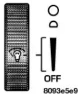
With the parking lights or headlights on, rotating the dimmer control for the interior lights on the Multi-Function Control Lever upward will increase the brightness of the instrument panel lights.
Dome Light Position
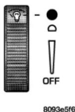
Rotate the dimmer control completely upward to the second detent to turn on the interior lights. The interior lights will remain on when the dimmer control is in this position. With the ignition key in the OFF position, the interior lights will automatically turn off in about 8 minutes if the dimmer control is left in the Dome light posi-
tion.
Interior light Defeat (OFF)
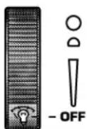
Rotate the dimmer control to the extreme bottom "OFF" position. The interior lights will remain off when the doors are open.
8093e60e
Parade Mode (Daytime Brightness Feature)
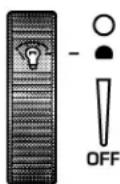
Rotate the dimmer control to the first detent (white semi-circle). This feature brightens the odometer and radio display when the parking lights or headlights are on during daylight conditions.
8093e650
Multi-Function Control Lever
The Multi-Function Control Lever controls the operation of the headlights, parking lights, turn signals, headlight beam selection, instrument panel light dimming, interior lights, the passing lights, and fog lights. The lever is located on the left side of the steering column.
96 UNDERSTANDING THE FEATURES OF YOUR VEHICLE
Headlights, Parking Lights, Instrument Panel Lights
Turn the end of the Multi-Function Control Lever to the first detent for parking light operation. Turn to the second detent for headlight operation.
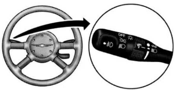
80c4f4a7
Multi-Function Control Lever
To change the brightness of the instrument panel lights, rotate the center portion of the Multi-Function Control Lever up or down.
Daytime Running Lights (Canada Only)
The front turn signal lights will come on as Daytime Running Lights whenever the ignition switch is on, the headlights are off, and the parking brake is off. The headlight switch must be used for normal night time driving.
Lights-on Reminder
If the headlights or parking lights are on after the ignition is turned OFF, a chime will sound to alert the driver when the driver's door is opened.
Fog Lights
The front fog light switch is on the Multi-Function Control Lever. To activate the front fog lights, turn on the parking lights or the low beam headlights and pull out the end of the control lever.
NOTE: The fog lights will only operate with the headlights on low beam. Selecting high beam headlights will turn off the fog lights.
Turn Signals
Move the Multi-Function Control Lever up or down and the arrows on each side of the instrument cluster flash to show proper operation of the front and rear turn signal lights. You can signal a lane change by moving the lever partially up or down without moving beyond the detent. If either light remains on and does not flash, or there is a very fast flash rate, check for a defective outside light bulb. If an indicator fails to light when the lever is moved, it would suggest that the fuse or indicator bulb is defective.
Highbeam/Lowbeam Select Switch
Pull the Multi-Function Control Lever towards you to switch the headlights to HIGH beam. Pull the control lever a second time to switch the headlights to LOW beam.
Passing Light
You can signal another vehicle with your headlights by lightly pulling the Multi-Function Control Lever toward you. This will cause the headlights to turn on at high beam and remain on until the lever is released.
98 UNDERSTANDING THE FEATURES OF YOUR VEHICLE
WINDSHIELD WIPERS AND WASHERS

The wipers and washers are operated by a switch on the control lever. The lever is located on the right side of the steering column. Move the control lever up to select the desired wiper speed.
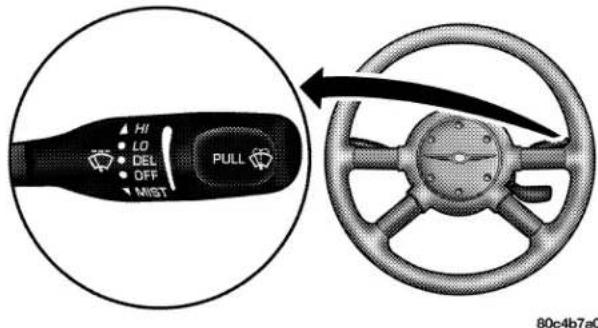
Windshield Wiper/Washer Control
Windshield Washers
To use the washer, pull the control lever toward you and hold while spray is desired. If the lever is pulled while in the delay range, the wiper will operate in low speed for two wipe cycles after the lever is released, and then resume the intermittent interval previously selected.
If the lever is pulled while in the OFF position, the wipers will operate for two wipe cycles, then turn OFF.
Mist Feature
Push down on the wiper control lever to activate a single wipe to clear the windshield of road mist or spray from a passing vehicle. As long as the lever is held down, the wipers will continue to operate.
CAUTION!
In cold weather, always turn off the wiper switch and allow the wipers to return to the park position before turning off the engine. If the wiper switch is left on and the wipers freeze to the windshield, damage to the wiper motor may occur when the vehicle is restarted.
Windshield Wiper Operation
Move the lever upward to the second detent for Low speed wiper operation, or to the third detent for High speed operation.
Intermittent Wiper System
Use the intermittent wiper when weather conditions make a single wiping cycle, with a variable pause between cycles, desirable. Move the lever to the DEL position, then select the delay interval by turning the end of the lever. Rotate the knob upward (clockwise) to decrease the delay time and downward (counterclockwise) to increase the delay time. The delay can be regulated from a maximum of approximately 18 seconds between cycles, to a cycle every second.
100 UNDERSTANDING THE FEATURES OF YOUR VEHICLE
Adding Washer Fluid
The fluid reservoir is located in the rear of the engine compartment on the passenger side and should be checked for fluid level at regular intervals. Fill the reservoir with windshield washer solvent (not radiator antifreeze) and operate the system for a few seconds to flush out the residual water.
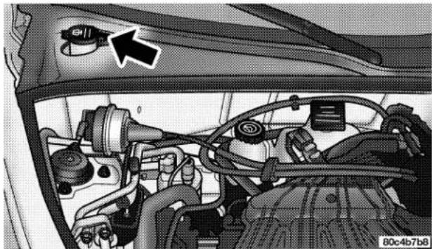
natural_image
Interior view of a car engine bay with visible hoses, springs, and a control knob (no text or symbols)Washer Fluid Reservoir
TILT STEERING COLUMN
To tilt the column, push down on the lever below the multi-function control lever and move the steering wheel up or down, as desired. Pull the lever back up to lock the column firmly in place.
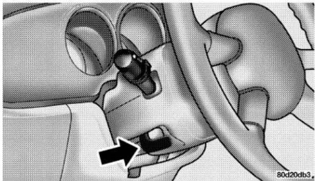
natural_image
Medical illustration of a human head and neck region with an arrow pointing to a specific anatomical structure (no text or labels present)Tilt Steering Column Control
WARNING!
Tilting the steering column while the vehicle is moving is dangerous. Without a stable steering column, you could lose control of the vehicle and have an accident. Adjust the column only while the vehicle is stopped. Be sure it is locked before driving.
102 UNDERSTANDING THE FEATURES OF YOUR VEHICLE
TRACTION CONTROL SWITCH — IF EQUIPPED
The TRAC indicator, located in the instrument cluster, will flash when the Traction Control System is in use.
The TRAC OFF switch is located on the instrument panel below the radio.
To turn the system OFF, press the TRAC OFF switch until the TRAC OFF indicator in the instrument cluster lights up.
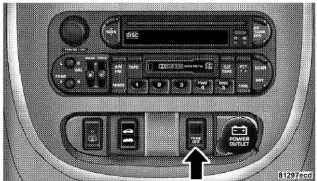
Traction Control Switch
To turn the system back ON, press the switch a second time until the TRAC OFF indicator turns OFF.
UNDERSTANDING THE FEATURES OF YOUR VEHICLE 103
NOTE: The Traction Control System indicator "TRAC OFF" will illuminate momentarily as a bulb check, each time the ignition switch is turned ON. This will occur even if you used the "TRAC OFF" switch to turn the system OFF.
NOTE: The Traction Control System will make buzzing or clicking sounds when the system is in operation.
ELECTRONIC SPEED CONTROL
When engaged, this device takes over the accelerator operation at speeds greater than 25 mph (40 km/h). The speed control lever is located on the right side of the steering wheel.

To Activate:
Push the ON/OFF button. The CRUISE indicator in the instrument cluster will illuminate. To turn the system OFF, push the ON/OFF button a second time. The CRUISE indicator will turn off. The system should be turned OFF when not in use.
WARNING!
Leaving the Electronic Speed Control system on when not in use is dangerous. You could accidentally set the system or cause it to go faster than you want. You could lose control and have an accident. Always leave the system OFF when you are not using it.
To Set At A Desired Speed:
When the vehicle has reached the desired speed, press down on the lever and release. Release the accelerator and the vehicle will operate at the selected speed.
NOTE: The vehicle should be traveling at a steady speed and on level ground before pressing the SET lever.
While in the AutoStick mode, speed control will only operate in third and fourth gear.
To Deactivate:
A soft tap on the brake pedal, pulling the speed control lever towards you "CANCEL", or normal brake or clutch pressure while slowing the vehicle will deactivate speed control without erasing the set speed memory. Pressing the ON/OFF button or turning off the ignition switch erases the set speed memory.
To Resume Speed:
To resume a previously set speed, push the "ACC/RES" lever up and release. Resume can be used at any speed above 20 mph (32 km/h).
To Vary The Speed Setting:
When the speed control is ON, speed can be increased by pushing up and holding "ACC/RES". Release the lever when the desired speed is reached, and the new speed will be set.
Tapping “ACC/RES” once will result in a 2 mph (3 km/h) speed increase. Each time the lever is tapped, speed increases so that tapping the lever three times will increase speed by 6 mph (10 km/h), etc.
To decrease speed while speed control is ON, push down and hold "COAST/SET". Release the lever when the desired speed is reached, and the new speed will be set.
Tapping the "COAST/SET" button once will result in a 1 mph (2 km/h) speed decrease. Each time the button is tapped, speed decreases.
Manual Transaxle:
Depressing the clutch pedal will disengage the speed control. A slight increase in engine RPM before the speed control disengages is normal.
Vehicles equipped with manual transaxles may need to be shifted into a lower gear to climb hills without speed loss.
WARNING!
Speed Control can be dangerous where the system can't maintain a constant speed. Your vehicle could go too fast for the conditions, and you could lose control. An accident could be the result. Don't use Speed Control in heavy traffic or on roads that are winding, icy, snow-covered, or slippery.
To Accelerate For Passing:
Depress the accelerator as you would normally. When the pedal is released, the vehicle will return to the set speed.
Using Speed Control On Hills
NOTE: The speed control system maintains speed up and down hills. A slight speed change on moderate hills is normal.
106 UNDERSTANDING THE FEATURES OF YOUR VEHICLE
Vehicles equipped with four speed automatic transaxles may experience a downshift to 3rd gear while climbing uphill or descending downhill. This downshift to 3rd gear is necessary to maintain vehicle set speed.
On steep hills a greater speed loss or gain may occur so it may be preferable to drive without speed control.
GARAGE DOOR OPENER — IF EQUIPPED
NOTE: The HomeLink® system will be disabled if the Vehicle Theft Alarm is in the Preamed, Armed or Alarming state. The HomeLink® system will only operate when the Vehicle Theft Alarm is in the Disarmed mode.
The HomeLink®Universal Transceiver replaces up to three remote controls (hand held transmitters) that operate devices such as garage door openers, motorized gates, or home lighting. It triggers these devices at the push of a button. The Universal Transceiver operates off your vehicle's battery and charging system; no batteries are needed.
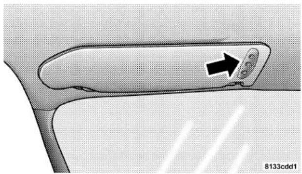
natural_image
Close-up of a car door handle with a black arrow pointing to a button (no text or symbols visible)HomeLink Buttons
For additional information on HomeLink ^® , call 1-800-355-3515, or on the internet at www.homelink.com.
WARNING!
A moving garage door can cause injury to people and pets in the path of the door. People or pets could be seriously or fatally injured. Only use this transceiver with a garage door opener that has a "stop and reverse" feature as required by federal safety standards. This includes most garage door opener models manufactured after 1982. Do not use a garage door opener without these safety features it could cause injury or death. Call toll-free 1-800-355-3515 or, on the Internet at www.homelink.com for safety information or assistance.
Programming The Universal Transceiver
For best results, install a new battery in the hand held transmitter before programming. If your garage door opener (located in the garage) is equipped with an antenna, make sure that the antenna is hanging straight down.
- Turn off the engine.
WARNING!
Vehicle exhaust contains carbon monoxide, a dangerous gas. Do not run the vehicle's exhaust while training the transceiver. Exhaust gas can cause serious injury or death.
108 UNDERSTANDING THE FEATURES OF YOUR VEHICLE
WARNING!
Your motorized door or gate will open and close while you are training the Universal Transceiver. Do not train the transceiver if people or pets are in the path of the door or gate. A moving door or gate can cause serious injury or death to people and pets or damage to objects.
- Erase the factory test codes by pressing the two outside buttons. Release the buttons when the light in the Universal Transceiver begins to flash (about 20 seconds).
NOTE: Step 2 does not have to be followed to program additional hand held transmitters.
- Choose one of the three Universal Transceiver buttons to program. Place the hand held controller one to three inches from the Universal Transceiver while keeping its indicator light in view.
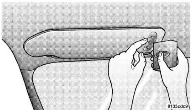
natural_image
Illustration of hands holding a camera on a car seat (no text or symbols visible)HomeLink Programming
- Using both hands, press the hand held transmitter button and the desired Universal Transceiver button. Do not release the buttons until step 5 has been completed.
NOTE: Some entry gates and garage door openers may require you to replace step 4 with the procedures listed under Canadian Programming.
- The indicator light in the Universal Transceiver will begin to flash, first slowly and then rapidly. The rapid flashing indicates successful programming. If after 90 seconds the indicator light does not flash rapidly or goes out, return to step 1 and repeat the procedure. To train the other buttons, repeat steps 3 and 4. Be sure to keep your hand held transmitters in case you need to retrain the Universal Transceiver.
NOTE: If you do not successfully program the Universal Transceiver to learn the signal of your hand held transmitter, refer to the Rolling Code Paragraph, or call toll free for customer assistance at 1-800-355-3515, or on the internet at www.homelink.com.
"Rolling Code" Programming
NOTE: If your hand held transmitter appears to program the Universal Transceiver, but your garage door or other device does not operate, and your device was
manufactured after 1996, your garage door opener or other device may have a "Rolling Code" system.
On garage door openers with the "Rolling Code" feature, the transmitter code changes after each use to prevent the copying of your code.
To check if your device is protected by a "Rolling Code" system:
- Check the owner's manual for the device for mention of "Rolling Codes".
- Press and hold the programmed button on the Universal Transceiver. If the Universal Transceiver indicator light flashes rapidly and then stays on after 2 seconds, the device has the "Rolling Code" feature.
To train a garage door opener (or other rolling code equipped devices) with the rolling code feature, follow these instructions after completing the Programming portion of this text:
NOTE: The assistance of a second person may make the following programming procedure quicker and easier.
- Locate the training button on the garage door motor head unit. The exact location and color of the button may vary by garage door opener manufacturer. If you have difficulty in locating the training button, check your garage door opener manual, or call 1-800-355-3515 or, on the Internet, at www.homelink.com.
- Press and hold the training button on the garage door opener head unit. This will activate the "training" light.
NOTE: After completing step 2, you have 30 seconds to start step 3.
- Return to the Universal Transceiver in the vehicle and firmly press and release the garage door button. Press and release the button a second time to complete the
training process. Some garage door openers may require you to do this procedure a third time to complete the training.
Your garage door opener should now recognize your Universal Transceiver. The remaining two buttons may now be programmed if this has not previously been done. Refer to the Programming instructions. You may use either your Universal Transceiver or your original hand-held transmitter to open you garage door.
Canadian Programming/Gate Programming
Canadian frequency laws, and the technology of some entry gates, require you to press and release the hand held transmitter button every two seconds during programming.
Continue to press and hold the Universal Transceiver button while you press and release the hand held transmitter button until the frequency signal has been learned.
The Universal Transceiver light will flash slowly and then rapidly when the programming is successful.
NOTE: When programming such a garage door opener or gate, unplug the device to prevent possible damage to the garage door or gate motor.
Operation
Press and hold the desired button on the Universal Transceiver until the garage door or other device begins to operate. The light in the display shows that the signal is being transmitted. The hand held transmitter may also be used at any time.
Reprogramming A Single Button
-
Press and hold the Universal Transceiver button to be reprogrammed. Do not release until step 4 has been completed.
-
When the indicator light begins to flash slowly (after 20 seconds) position the hand held transmitter one to three inches away from the button to be trained.
- Press and hold the hand held transmitter button.
- The Universal Transceiver indicator light will begin to flash, first slowly, then rapidly. When the indicator lights begin to flash rapidly, release both buttons.
Security
If you sell your vehicle, be sure to erase the frequencies.
To erase all of the previously trained frequencies, hold down both outside buttons until the indicator light begins to flash.
This device complies with part 15 of FCC rules and with RS-210 of Industry Canada. Operation is subject to the following conditions:
- This device may not cause harmful interference.
112 UNDERSTANDING THE FEATURES OF YOUR VEHICLE
- This device must accept any interference that may be received including interference that may cause undesired operation.
NOTE: Changes or modifications not expressly approved by the party responsible for compliance could void the user's authority to operate the equipment.
HomeLink® is a trademark owned by Johnson Controls, Inc.
ELECTRICAL POWER OUTLETS
These three outlets include tethered caps, labeled with a key symbol or battery symbol, indicating power source. All outlets are protected by a single 20 Amp fuse.
The outlet that is located in the front of the center floor console is a conventional cigar lighter outlet.
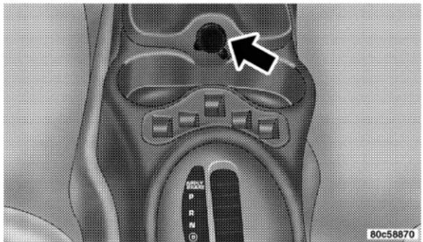
natural_image
Medical scan image showing internal anatomical structures with a black arrow pointing to a specific region (no text or symbols present)Power Outlet
It will accept a cigar lighter unit, which is part of the optional Smokers Package. To preserve the heating element of the cigar lighter unit, do not hold the lighter in the heating position. As a child safety precaution, this outlet is powered by the ignition switch, only when the switch is in the "ON" or "ACCESSORY" positions.
UNDERSTANDING THE FEATURES OF YOUR VEHICLE 113
Another of the outlets is in the Accessory Switch Bank, in the center of the instrument panel.
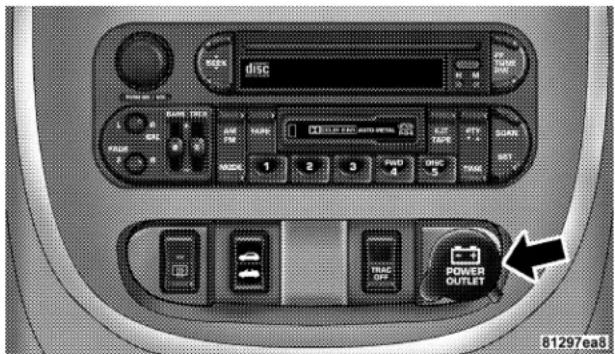
Power Outlet
This outlet is powered directly by the battery, regardless of the ignition switch position. All accessories connected to this outlet should be removed or turned off when the vehicle is not in use, to protect the battery against discharge.
The third outlet is located in the right rear cargo area.
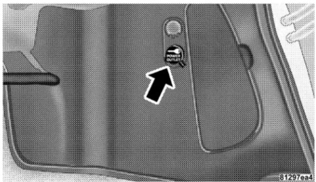
Rear Power Outlet
114 UNDERSTANDING THE FEATURES OF YOUR VEHICLE
Since this outlet is remote from the driver, it is powered by the ignition switch, only when it is in the "ON" or "ACCESSORY" positions, to protect the battery against discharge. Note: Neither of the power outlets will accept a cigar lighter unit. They are intended only for accessory usage.
Electrical Outlet Use With Engine Off
CAUTION!
- Many accessories that can be plugged in draw power from the vehicle's battery, even when not in use (i.e. cellular phones, etc.). Eventually, if plugged in long enough, the vehicle's battery will discharge sufficiently to degrade battery life and/or prevent engine starting.
- Accessories that draw higher power (i.e. coolers, vacuum cleaners, lights, etc.), will degrade the battery even more quickly. Only use these intermittently and with greater caution.
- After the use of high power draw accessories, or long periods of the vehicle not being started (with accessories still plugged in), the vehicle must be driven a sufficient length of time to allow the generator to recharge the vehicle's battery.
UNDERSTANDING THE FEATURES OF YOUR VEHICLE 115
CONSOLE FEATURES
The console has two front cup holders, a coin holder, 12 volt power outlet, and front and rear storage trays. There are additional cup holders; one is molded in the center of the console to hold large cups and the other is at the rear of the console to serve passengers in the rear seat. The floor console power outlet will also operate a conventional cigar lighter unit (if equipped with an optional Smoker's Package).

natural_image
Medical illustration of pelvic anatomy showing internal organs and structures (no text or labels)Front Cupholders
CAUTION!
- Many accessories that can be plugged into the 12 volt power outlet, draw power from the vehicle's battery, even when not in use; i.e. cellular phones, etc. Eventually, if plugged in long enough, the vehicle's battery will discharge sufficiently to degrade battery life and/or prevent engine starting.
- Accessories that draw higher power such as coolers, vacuum cleaners, lights, etc., will discharge the battery even more quickly. Only use these intermittently and with greater caution.
- After the use of high power draw accessories, or long periods of the vehicle not being started, (with accessories still plugged in), the vehicle must be driven a sufficient length of time to allow the generator to recharge the vehicle's battery.
STORAGE
Front Seat Storage Bin
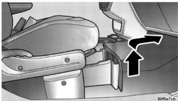
natural_image
Interior view of a car seatbelt mechanism with directional arrow indicating movement (no text or symbols)Front Seat Storage Bin
The storage bin is located under the front passenger's seat. To open lift up on the handle and pull the storage bin forward.
Storage Pockets
There are also Storage pockets located on each door trim panel.
UNDERSTANDING YOUR INSTRUMENT PANEL
CONTENTS
■Instrument Panel Features....1 2 3
■Instrument Cluster....124
■ Instrument Cluster—Turbo, With AutoStick ....125
■Instrument Cluster—Turbo, Without AutoStick .. 126
■Instrument Cluster Descriptions ..... 1 2 7
Electronic Digital Clock 134
□Clock Setting Procedure ..... 1 3 4
■ Radio General Information .....135
□Radio Broadcast Signals....135
□Two Types Of Signals....135
□Electrical Disturbances....135
□AM Reception 135
□FM Reception 135
Sales Code RAZ—AM/ FM Stereo Radio With Cassette Tape Player, CD Player And CD Changer Controls 136
□ Operating Instructions — Radio .....136
□ Power Switch, Volume Control .....136
□Seek Button (Radio Mode)....136
UNDERSTANDING YOUR INSTRUMENT PANEL
□Tuning....137
□Radio Data System (RDS)....137
□PTY (Program Type) Button ..... 1 3 7
□Balance....139
□Fade....139
□Tone Control....139
□AM/FM Selection....139
□Scan Button....139
□To Set The Radio Push-Button Memory ..... 1 4 0
□To Change From Clock To Radio Mode ..... 1 4 0
□ Operating Instructions — Tape Player .....140
□Seek Button....140
□Fast Forward (FF)....141
□Rewind (RW)....141
□Tape Eject....141
□Scan Button....141
□Changing Tape Direction....141
□Metal Tape Selection....141
□Pinch Roller Release....142
□Noise Reduction....142
□ Operating Instructions — CD Player .....142
□Inserting The Compact Disc....142
□Seek Button....143
□EJT CD (Eject) Button 143
□FF/Tune/RW....144
□Program Button 4 (Random Play) ..... 1 4 4
UNDERSTANDING YOUR INSTRUMENT PANEL 121
□Mode....144
□Tape CD Button....144
□Time Button....145
□Scan Button....145
□CD Changer Control Capability
— If Equipped....1 4 5
■Sales Code RBB—AM/FM Stereo Radio With Cassette Tape Player And CD Changer
Capability 146
□Operating Instructions....147
□Power Button....147
□Electronic Volume Control....147
□Seek....147
□Tune 148
□ To Set The Push-Button Memory .....148
□Balance 148
□Fade 148
□Bass And Treble Tone Control....149
□AM/FM Selection....149
□Mode Button 149
□Cassette Player Features 149
□CD Changer Control Capability
— If Equipped....1 5 1
□ Radio Display Messages .....152
■Sales Code RBK—AM/ FM Stereo Radio With
CD Player And CD Changer Controls ..... 1 5 3
□Radio Operation....153
□CD Player Operation....155
122 UNDERSTANDING YOUR INSTRUMENT PANEL
□CD Changer Control Capability
— If Equipped .... 1 5 7
□Radio Display Messages....158
■Sales Code RBQ—AM/FM Stereo Radio With 6 - Disc CD Changer....159
□Radio Operation....160
□CD Player Operation....162
■Sales Code RB1—AM/FM Stereo Radio With DVD/GPS Navigation System....166
■Cassette Tape And Player Maintenance ..... 1 6 7
■CD/DVD Disc Maintenance....168
■Radio Operation And Cellular Phones ..... 1 6 8
■Climate Controls....169
□Air Conditioning....169
□Operating Tips....174
■Electric Rear Window Defroster....176
INSTRUMENT PANEL FEATURES
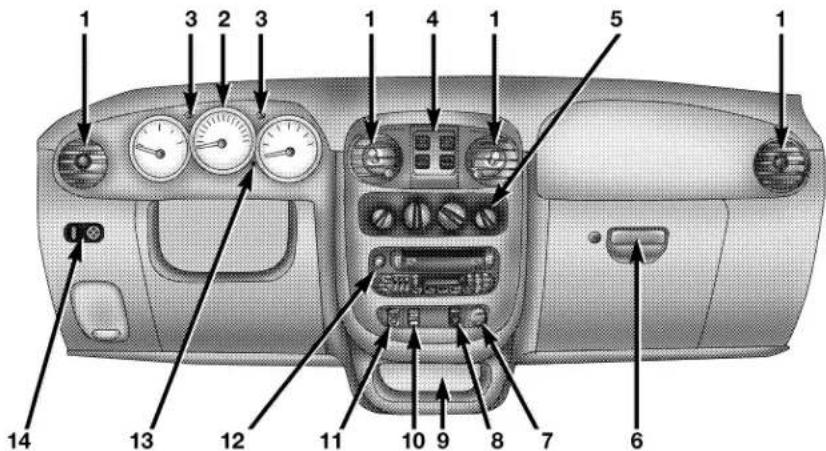
- Air Outlets
- Instrument Cluster
- Turn Signal Indicators
- Power Window Switches
- Climate Control
- Glove Compartment
- Power Outlet
- Trac Off Switch
- Storage Bin
- Power Convertible Top Switch
- Rear Window Defrost Switch
- Radio
- Trip Odometer Button
- Power Mirror Switch
812e3747
INSTRUMENT CLUSTER
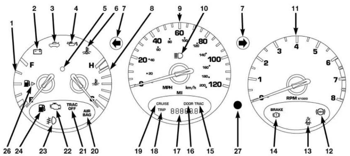
810a4d41
INSTRUMENT CLUSTER—TURBO, WITH AUTOSTICK
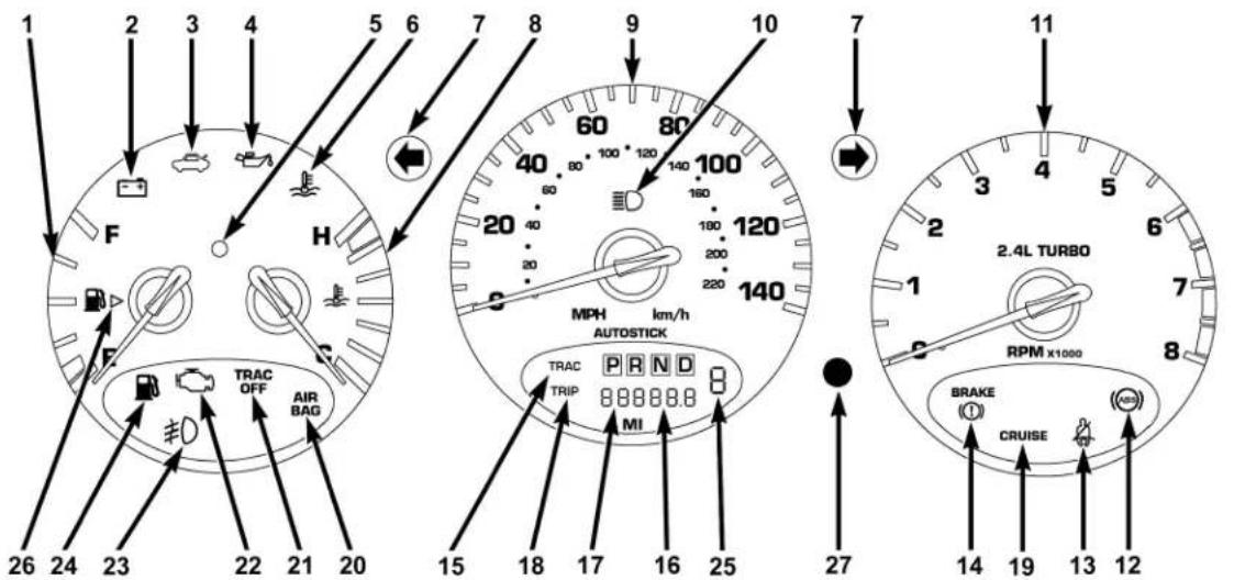
810a4d5d
INSTRUMENT CLUSTER—TURBO, WITHOUT AUTOSTICK
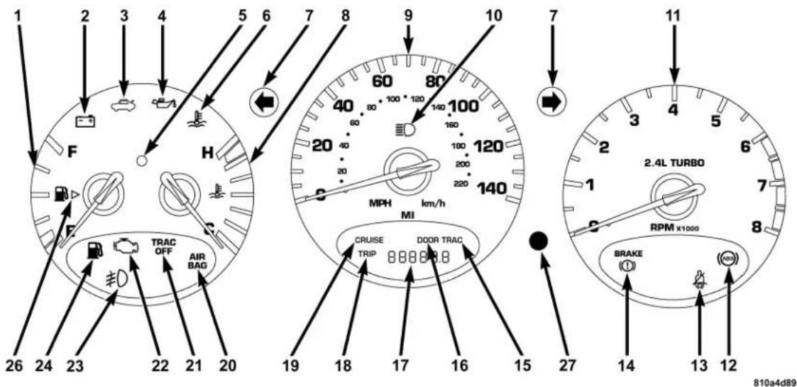
INSTRUMENT CLUSTER DESCRIPTIONS
1. Fuel Gauge

When the ignition switch is in the ON position, the pointer will show the level of fuel remaining in the fuel tank.
2. Charging System Light

This light shows the status of the electrical charging system. The light should come on briefly when the ignition is first turned ON and remain on briefly as a bulb check. If the light stays on or comes on while driving, it means that there is a problem with the charging system. Obtain SERVICE IMMEDIATELY.
3. Deck Lid Ajar

This light comes on if the deck lid is not completely closed.
4. Oil Pressure Light

Shows low engine oil pressure. The light will come on and remain on when the ignition switch is from the OFF to the ON position, and the light turn off after the engine is started. If the bulb does me on during starting, have the system checked by horized dealer.
If the light comes on and remains on while driving, stop the vehicle and shut off the engine. DO NOT OPERATE THE VEHICLE UNTIL THE CAUSE IS CORRECTED.
The light does not show the quantity of oil in the engine. This can be determined using the procedure shown in Section 7. (See page 257 for more information.)
5. Theft Alarm Light — If Equipped
This light will flash rapidly for several seconds when the alarm system is arming. The light will begin to flash slowly indicating that the system is armed.
6. Engine Temperature Warning Light

This light warns of an overheated engine condition. If the engine is critically hot, a warning chime will sound 10 times. After the chime turns off, the will still be critically hot until the light goes out.
7. Turn Signal Indicators

The arrows will flash in unison with the exterior turn signal, when using the turn signal lever.
NOTE: Turn signal bulbs are located in the Instrument Panel. (See page 97 for more information.)
8. Temperature Gauge

The temperature gauge shows engine coolant temperature. Any reading below the red area of the gauge shows that the engine cooling system is ing properly. The gauge pointer may show a than normal temperature when driving in hot er, up mountain grades, in heavy stop and go or when towing a trailer.
If the pointer rises to the H (red) mark, the instrument cluster will sound a chime. Pull over and stop the vehicle. Idle the vehicle with the air conditioner turned off until the pointer drops back into the normal range. If the pointer remains on the H (red) mark, turn the engine off immediately and call for service.
There are steps that you can take to slow down an impending overheat condition. If your air conditioning is on, turn it off. The air conditioning system adds heat to the engine cooling system and turning off the A/C removes this heat. You can also turn the Temperature control to maximum heat, the Mode control to Floor and the Fan control to High. This allows the heater core to act as a supplement to the radiator and aids in removing heat from the engine cooling system.
9. Speedometer
Indicates vehicle speed.
10. High Beam Indicator
This light shows that the headlights are on high beam. Pull the turn signal lever toward the steering wheel to switch the headlights from high or low beam.
11. Tachometer
The white area of the scale shows the permissible engine revolutions-per-minute (rpm x 1000) for each gear range. Before reaching the red area, ease up on the accelerator to prevent engine damage.
12. Anti-Lock Warning Light (ABS) — If Equipped

This light monitors the Anti-Lock Brake System (ABS) described elsewhere in this manual. This light will come on when the ignition key is turned to the ON position and may stay on for as long as four seconds.
If the ABS light remains on or comes on during driving, it indicates that the Anti-Lock portion of the brake system is not functioning and that service is required, however, the conventional brake system will continue to operate normally provided that the BRAKE warning light is not on.
If the ABS light is on, the brake system should be serviced as soon as possible to restore the benefit of Anti-Lock Brakes.
The warning light should be checked frequently to assure that it is operating properly. Turn the ignition key to the on position, but do not start the vehicle. The light should come on. If the light does not come on, have the system checked by an authorized dealer.
13. Seat Belt Reminder Light

When the ignition switch is first turned ON, this light will come on for about six seconds. A chime will sound if you have not pulled the shoulder belt
130 UNDERSTANDING YOUR INSTRUMENT PANEL
out of the retractor. This is a reminder to "buckle up". If you do not buckle up, the light will remain on.
14. Brake System Warning Light

This light monitors various brake functions, including brake fluid level and parking brake application. If the brake light comes on, it may indicate that the parking brake is applied, or there is a low brake fluid level. On vehicles equipped with Anti-lock brakes (ABS), it may also indicate an ABS malfunction that could lead to reduced braking performance.
WARNING!
Driving a vehicle with the brake light on is dangerous. A significant decrease in braking performance or vehicle stability during braking may occur. It will take you longer to stop the vehicle or will make your vehicle harder to control. You could have an accident. Have the vehicle checked immediately.
The operation of the Brake Warning light can be checked by turning the ignition key from the OFF to the ON position. The light should illuminate for three seconds, or until the engine is started, whichever comes first. The light should then go out unless the parking brake is applied or a brake fault is detected. If the light does not illuminate, have the light inspected and serviced as soon as possible.
The light will also come on when the parking brake is applied with the ignition switch in the ON position.
NOTE: This light shows only that the parking brake is applied. It does not show the degree of brake application.
If the parking brake is off and the light remains on, have the brake system inspected as soon as possible.
15. Trac Indicator — If Equipped
The TRAC Light will come on momentarily as a bulb check when the ignition switch is first turned ON.
The light will flash when the Traction Control System is controlling traction.
16. Door Ajar Indicator
This vacuum fluorescent display indicator illuminates the word "DOOR", when a door is not completely closed. If the door is open for more than 8 minutes, the light will turn off.
17. Odometer/Trip Odometer
The odometer shows the total distance the vehicle has been driven. The trip odometer shows the trip distance since the last reset.
U.S. Federal regulations require that upon transfer of vehicle ownership, the seller certify to the purchaser the correct mileage that the vehicle has been driven. Therefore, if the odometer reading changes during repair or replacement, be sure to keep a record of the reading before and after the service so the correct mileage can be determined.
18. Trip Indicator
This vacuum fluorescent display indicator will illuminate when the Trip Odometer is in use.
By pushing the trip button, located next to the instrument cluster, the odometer will toggle between total distance
132 UNDERSTANDING YOUR INSTRUMENT PANEL
and trip distance. In the trip odometer mode, holding the trip button for more than 2 seconds will reset the trip odometer to "0".
19. Cruise Indicator — If Equipped
CRUISE This indicator shows that the Speed Control System is ON.
NOTE: The word "SET" will not illuminate when the Speed Control System is on.
20. Airbag Light
AIR BAG The light comes on and remains on for 6 to 8 seconds as a bulb check when the ignition switch is first turned ON. If the light does not come on during starting, stays on, or comes on while driving, have the system checked by an authorized dealer.
21. Trac Off Light — If Equipped
The TRAC OFF light will illuminate momentarily as a bulb check when the ignition switch is first turned ON. If the light does not come on, have the system checked.
The light will also come on if:
- The Traction Control switch has been used to turn the system off,
• There is an anti-lock system failure,
• There is a Traction Control system failure, - The system has been automatically deactivated to prevent damage to the brake system due to overheated brake temperatures.
NOTE: Extended heavy use of Traction Control may cause the system to deactivate and turn on the TRAC OFF Light. This is to prevent overheating of the brake system and is a normal condition. The system will remain
disabled for about 4 minutes until the brakes have cooled. The system will automatically reactivate and turn off the TRAC OFF Light.
22. Malfunction Indicator Light
This light is part of an onboard diagnostic system called OBD that monitors emissions, engine, and automatic transmission control systems. The light will illuminate when the key is in the ON/RUN position before engine start. If the bulb does not come on when turning the key from OFF to ON/RUN, have the condition checked promptly.
Certain conditions such as a loose or missing gas cap, poor fuel quality, etc. may illuminate the light after engine start. The vehicle should be serviced if the light stays on through several of your typical driving cycles. In most situations the vehicle will drive normally and will not require towing.
If the Malfunction Indicator Light flashes when the engine is running, serious conditions may exist that could lead to immediate loss of power or severe catalytic converter damage. The vehicle should be serviced as soon as possible if this occurs. (See page 254 for more information.)
23. Front Fog Light Indicator — If Equipped

This light shows when the front fog lights are ON.
24. Low Fuel Light

When the fuel level drops to about 1/8 tank, the fuel symbol will light and a single chime will sound. The light will remain on until fuel is added.
If the fuel level drops to approximately 1.0 gallon (3.75 Liter), the fuel symbol will flash several times and the chime will sound several times.
134 UNDERSTANDING YOUR INSTRUMENT PANEL
25. AutoStick Gear Position—If Equipped
This vacuum fluorescent display indicator illuminates when the gearshift lever is moved to the AutoStick position and shows the current gear selection.
26. Fuel Door Reminder
This symbol is a reminder that the Fuel Filler Door is located on the front passenger's (right) side of the vehicle.
27. Odometer/Trip Odometer Reset Knob
Press the knob to switch between the odometer and trip odometer. While the trip odometer is being displayed, press and hold this knob for a few seconds to reset the trip odometer to zero miles/kilometers.
ELECTRONIC DIGITAL CLOCK
The clock and radio each use the display panel built into the radio. A digital readout shows the time in hours and minutes whenever the ignition switch is in the ON or ACC position and the time button is pressed.
When the ignition switch is in the OFF position, or when the radio frequency is being displayed, time keeping is accurately maintained.
Clock Setting Procedure
- Turn the ignition switch to the ON or ACC position and press the time button. Using the tip of a ballpoint pen or similar object, press either the hour (H) or minute (M) buttons on the radio.
- Press the H button to set hours or the M button to set minutes. The time setting will increase each time you press a button.
RADIO GENERAL INFORMATION
Radio Broadcast Signals
Your new radio will provide excellent reception under most operating conditions. Like any system, however, car radios have performance limitations, due to mobile operation and natural phenomena, which might lead you to believe your sound system is malfunctioning. To help you understand and save you concern about these “apparent” malfunctions, you must understand a point or two about the transmission and reception of radio signals.
Two Types of Signals
There are two basic types of radio signals... AM or Amplitude Modulation, in which the transmitted sound causes the amplitude, or height, of the radio waves to vary... and FM or Frequency Modulation, in which the frequency of the wave is varied to carry the sound.
Electrical Disturbances
Radio waves may pick up electrical disturbances during transmission. They mainly affect the wave amplitude, and thus remain a part of the AM reception. They interfere very little with the frequency variations that carry the FM signal.
AM Reception
AM sound is based on wave amplitude, so AM reception can be disrupted by such things as lightning, power lines and neon signs.
FM Reception
Because FM transmission is based on frequency variations, interference that consists of amplitude variations can be filtered out, leaving the reception relatively clear, which is the major feature of FM radio.
NOTE: On vehicles so equipped the radio, steering wheel radio controls and 6 disc CD/DVD changer will
136 UNDERSTANDING YOUR INSTRUMENT PANEL
remain active for up to 45 seconds after the ignition switch has been turned off. Opening a vehicle front door will cancel this feature.
SALES CODE RAZ—AM/ FM STEREO RADIO WITH CASSETTE TAPE PLAYER, CD PLAYER AND CD CHANGER CONTROLS
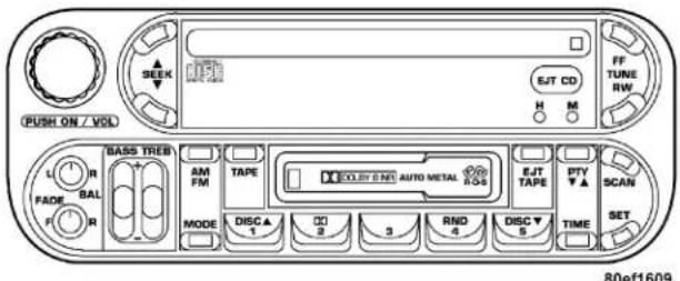
RAZ Radio
Operating Instructions — Radio
NOTE: Power to operate the radio is controlled by the ignition switch. It must be in the ON or ACC position to operate the radio.
Power Switch, Volume Control
Press the ON/VOL control to turn the radio on. Turn the volume control clockwise to increase the volume. The volume will be displayed and continuously updated while the button is pressed.
Seek Button (Radio Mode)
Press and release the Seek button to search for the next station in either the AM or FM mode. Press the top of the button to seek up and the bottom to seek down. Holding the button will by pass stations until you release the button.
Tuning
Press the TUNE control up or down to increase or decrease the frequency. If you press and hold the button, the radio will continue to tune until you release the button. The frequency will be displayed and continuously updated while the button is pressed.
Radio Data System (RDS)
The Radio Data System allows radio broadcasting stations to send data signals on a subcarrier frequency which is added to the stereo signal. RDS was developed to give FM receivers user-friendly features, such as Program Service name (PS) and Program Type (PTY). Program Service name is typically used by the broadcaster to display the station's name or call letters, for example "WNIC". Typically these are 8 characters in length and are displayed by the radio for those stations which are broadcasting this information. PTY (Program Type) is used to characterize the station's program material, for example "Rock Music".
PTY (Program Type) Button
Pressing this button once will turn on the PTY mode for 5 seconds. If no action is taken during the 5 second time out the PTY icon will turn off. Pressing the PTY button within 5 seconds will allow the program format type to be selected. Many radio stations do not currently broadcast PTY information.
Toggle the PTY button to select the following format types:
| Program Type Radio | Display |
| Adult Hits Adlt Hit | |
| Classical Classicl | |
| Classic Rock | Cls Rock |
| College | College |
| Country Country | |
| Information Inform | |
| Jazz Jazz | |
| Foreign Language Language | |
| News News | |
| Nostalgia Nostalga | |
| Oldies Oldies | |
| Personality Persnity | |
| Public Public | |
| Rhythm and Blues R & B | |
| Religious Music Rel Musc | |
| Religious Talk Rel Talk | |
| Rock Rock | |
| Soft | Soft |
| Soft Rock Soft Rck | |
| Soft Rhythm and Blues | Soft R&B |
| Program Type Radio | Display |
| Sports | Sports |
| Talk | Talk |
| Top 40 | Top 40 |
| Weather | Weather |
By pressing the SEEK button when the PTY icon is displayed, the radio will be tuned to the next frequency station with the same selected PTY name. The PTY function only operates when in the FM mode.
The radio display will flash "SEEK" and the selected PTY program type when searching for the next PTY station. If no station is found with the selected PTY program type, the radio will return to the last preset station.
If a preset button is activated while in the PTY (Program Type) mode, the PTY mode will be exited and the radio will tune to the preset station.
Pressing PTY, then SCAN will scan the FM Band and stop at all RDS stations. Each RDS station will be played for a 5 second scan once around the FM Band and stop at the last station. The PTY icon will then turn off.
Balance
The Balance control adjusts the left-to-right speaker balance. Push in the button and it will pop out. Adjust the balance and push the button back in. The balance will be displayed and continuously updated while the button is turned.
Fade
The Fade control provides for balance between the front and rear speakers. Push in the button and it will pop out. Adjust the balance and push the button back in. The fade will be displayed and continuously updated while the button is turned.
Tone Control
Slide the Bass and/or Treble controls up or down to adjust the sound for the desired tone. The treble, and bass will be displayed and continuously updated while the slide is moved.
AM/FM Selection
Press the AM/FM button to change from AM to FM. The operating mode will be displayed next to the station frequency. The display will show ST when a stereo station is received.
Scan Button
Pressing the SCAN button causes the tuner to search for the next station, in either AM or FM, pausing for 5 seconds at each listenable station before continuing to the next.
Pressing the AM/FM button continues the search in the alternate frequency band.
To stop the search, press SCAN a second time.
140 UNDERSTANDING YOUR INSTRUMENT PANEL
To Set The Radio Push-button Memory
When you are receiving a station that you wish to commit to push-button memory, press the SET button. SET 1 will show in the display window. Select the push-button you wish to lock onto this station and press and release that button. If a station is not selected within 5 seconds after pressing the SET button, the station will continue to play but will not be locked into push-button memory.
You may add a second station to each push-button by repeating the above procedure with this exception: Press the SET button twice and SET 2 will show in the display window. Each button can be set for SET 1 and SET 2 in both AM and FM. This allows a total of 10 AM and 10 FM stations to be locked into memory. You can recall the stations stored in SET 2 memory by pressing the push-button twice.
To Change From Clock To Radio Mode
Press the Time button to change the display between radio frequency and time.
Operating Instructions — Tape Player
Insert the cassette with the exposed tape side toward the right and the mechanical action of the player will gently pull the cassette into the play position.
NOTE: When subjected to extremely cold temperatures, the tape mechanism may require a few minutes to warm up for proper operation. Sometimes poor playback may be experienced due to a defective cassette tape. Clean and demagnetize the tape heads at least twice a year.
Seek Button
Press the SEEK button up for the next selection on the tape and down to return to the beginning of the current selection.
Press the SEEK button up or down to move the track number to skip forward or backward 1 to 6 selections.
Press the SEEK button once to move 1 selection, twice to move 2 selections, etc.
Fast Forward (FF)
Press the FF button up momentarily to advance the tape in the direction that it is playing. The tape will advance until the button is pressed again or the end of the tape is reached. At the end of the tape, the tape will play in the opposite direction.
Rewind (RW)
Press the RW button momentarily to reverse the tape direction. The tape will reverse until the button is pressed again or until the end of the tape is reached. At the end of the tape, the tape will play in the opposite direction.
Tape Eject
Press the EJT Tape button and the cassette will disengage and eject from the radio.
Scan Button
Press this button to play 10 seconds of each selection.
Press the scan button a second time to cancel the feature.
Changing Tape Direction
If you wish to change the direction of tape travel (side being played), press the PTY button. The lighted arrow in the display window will show the new direction.
Metal Tape Selection
If a standard metal tape is inserted into the player, the player will automatically select the correct equalization and the 70 symbol will appear in the display window.
142 UNDERSTANDING YOUR INSTRUMENT PANEL
Pinch Roller Release
If ignition power or the radio ON/OFF switch are turned off, the pinch roller will automatically retract to protect the tape from any damage. When power is restored to the tape player, the pinch roller will automatically reengage and the tape will resume play.
Noise Reduction
The Dolby Noise Reduction System* is on whenever the tape player is on, but may be switched off.
To turn off the Dolby Noise reduction System: Press the Dolby button (button 2) after you insert the tape. The NR light in the display will go off when the Dolby System is off. The Dolby System is automatically reactivated each time a tape is inserted.
* "Dolby" noise reduction manufactured under license from Dolby Laboratories Licensing Corporation. Dolby and the double-D symbol are trademarks of Dolby Laboratories Licensing Corporation.
Operating Instructions — CD Player
NOTE: The ignition switch must be in the ON or ACC position and the volume control ON before the CD player will operate.
CAUTION!
This CD player will accept 4 34 inch (12 cm) discs only. The use of other sized discs may damage the CD player mechanism.
Inserting The Compact Disc
The CD player contained within the radio is not a multi-disc changer, and will only accept one CD. Gently insert one CD into the CD player with the CD label facing up. The CD will automatically be pulled into the CD Player.
If the volume control is ON, the unit will switch from radio to CD mode and begin to play. The display will show the track number and index time in minutes and seconds. Play will begin at the start of track one.
NOTE:
- You may eject a disc with the radio OFF. The ignition switch must be in the ON or ACC position to insert a disc with the radio OFF.
- If you insert a disc with the ignition ON and the radio OFF, the CD will automatically be pulled into the CD Player and the display will show the time of day. If you insert a disc with the ignition OFF, the display will show the time of day for about 5 seconds, then go out.
Seek Button
Press the top of the SEEK button for the next selection on the CD. Press the bottom of the button to return to the beginning of the current selection, or return to the beginning of the previous selection if the CD is within the first 10 seconds of the current selection.
EJT CD (Eject) Button
Press this button and the disc will unload and move to the entrance for easy removal. The unit will switch to the radio mode.
If you do not remove the disc within 15 seconds, it will be reloaded. The radio mode will continue to appear.
The disc can be ejected with the radio OFF.
144 UNDERSTANDING YOUR INSTRUMENT PANEL
FF/TUNE/RW
Press FF (Fast Forward) and the CD player will begin to fast forward until FF is released. The RW (Reverse) button works in a similar manner.
Program Button 4 (Random Play)
Press this button while the CD is playing to activate Random Play. This feature plays the tracks on the selected disc in random order to provide an interesting change of pace.
Press the SEEK button to move to the next randomly selected track.
Press TUNE FF to fast forward through the tracks. Press the FF button a second time to stop the fast forward feature. If TUNE RW is pressed, the current track will reverse to the beginning of the track and begin playing.
Press button 4 a second time to stop Random Play.
MODE
Press the MODE button to select between the tape player, CD player, or satellite radio (if equipped).
To select Satellite Radio (if equipped), press the MODE button until the word SIRIUS appears. The following will be displayed in this order: After three seconds, the current channel name and number will be displayed for five seconds. The current program type and channel number will then be displayed for five seconds. The current channel name and number will then be displayed until an action occurs. A CD or tape may remain in the player while in the Satellite Radio mode.
Tape CD Button
Press this button to select between CD player and Tape player.
Time Button
Press this button to change the display from elapsed CD playing time to time of day.
Scan Button
Press this button to play the first 10 seconds of each track. To stop the scan function, press the button a second time.
CD Changer Control Capability — If Equipped
This radio is compatible with a remote mounted CD changer available through Mopar Accessories. The following instructions are for the radio controls that operate this CD changer.
Mode Button
To activate the CD changer, press the MODE button until CD information appears on the display.
Disc Up/Program Button 1
Press the DISC up (button 1) button to play the next available disc.
Disc Down/Program Button 5
Press the DISC down (button 5) button to play the previous disc.
Seek Button
Press the SEEK up or down to select another track on the same disc. A SEEK symbol will appear on the display.
Fast Forward And Rewind Buttons
Press and hold the FF button for fast forward. Press and hold the RW button for fast reverse.
The audio output can be heard when fast forward and fast reverse are activated.
Random Play (RND)
Press the Random button to play the tracks on the selected disc in random order for an interesting change of pace.
Random can be cancelled by pressing the button a second time or by ejecting the CD from the changer.
146 UNDERSTANDING YOUR INSTRUMENT PANEL
CD Diagnostic Indicators
When driving over a very rough road, the CD player may skip momentarily. Skipping will not damage the disc or the player, and play will resume automatically.
As a safeguard and to protect your CD player, one of the following warning symbols may appear on your display.
A CD HOT symbol indicates the player is too hot.
CD HOT will pause the operation. Play can be resumed when the operating temperature is corrected or another MODE is selected.
An ERR symbol will appear on the display if the laser is unable to read the Disc data for the following reasons:
- Excessive vibration
• Disc inserted upside down - Damaged disc
• Water condensation on optics
SALES CODE RBB—AM/FM STEREO RADIO WITH CASSETTE TAPE PLAYER AND CD CHANGER CAPABILITY
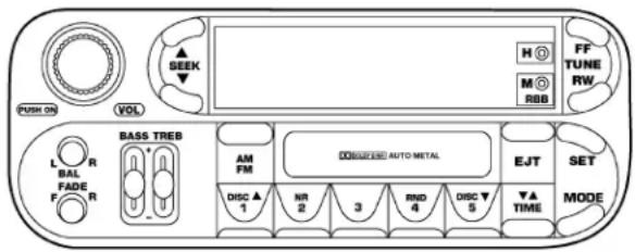
RBB Radio
Operating Instructions
NOTE: Power to operate the radio is supplied through the ignition switch. It must be in the ON or ACC position to operate the radio.
NOTE: When first learning the control functions, the user should set the controls as shown in the following list.
Tone Controls...As illustrated. Speaker Control...Centered.
Power Button
The volume control/power button pops out when pressed, this turns the sound system ON in the mode last used. Pushing the button back in turns the sound system OFF.
Electronic Volume Control
The electronic volume control turns continuously (360 degrees) in either direction without stopping. Turning the volume control to the right increases the volume and to the left decreases it.
When the audio system is turned on, the sound will be set at the same volume level as last played.
For your convenience, the volume can be turned down, but not up, when the audio system is off and the ignition is ON.
Seek
Press and release the SEEK button to search for the next station in either the AM or FM mode. Press the top of the button to seek up and the bottom to seek down. The radio will remain tuned to the new station until you make another selection. Holding the button will bypass stations without stopping until you release it.
148 UNDERSTANDING YOUR INSTRUMENT PANEL
Tune
Press the TUNE control up or down to increase or decrease the frequency. If the button is pushed and held, the radio will continue to tune until the button is released. The frequency will be displayed and continuously updated while the button is pushed.
To Set The Push-Button Memory
When you are receiving a station that you wish to commit to push-button memory, press the SET button. The symbol SET 1 will now show in the display window. Select the "1-5" button you wish to lock onto this station and press and release that button. If a button is not selected within 5 seconds after pressing the SET button, the station will continue to play but will not be locked into push-button memory.
You may add a second station to each push-button by repeating the above procedure with this exception: Press the SET button twice and SET 2 will show in the display window. Each button can be set for SET 1 and SET 2 in both AM and FM. This allows a total of 10 AM and 10 FM stations to be locked into push-button memory. The stations stored in SET 2 memory can be selected by pressing the push-button twice.
Every time a preset button is used a corresponding button number will be displayed.
Balance
The balance control adjusts the left-to-right speaker balance. Press the BAL button in and it will pop out. Adjust the balance and push the button back in.
Fade
The fade control provides for balance between the front and rear speakers. Press the FADE button in and it will pop out. Adjust the balance and push the button back in.
Bass and Treble Tone Control
The tone controls consist of 2 separate bands. The bass band is on the left, and the treble band is on the right. Each band is adjusted by a slider control with a detent at the mid-position. Moving the control up or down increases or decreases amplification of that band. The mid position provides a balanced output.
AM/FM Selection
Press the AM/FM button to change from AM to FM. The operating mode will be displayed next to the station frequency. The display will show ST when a stereo station is received in the FM mode.
Mode Button
Press the MODE button to select between the cassette tape player, CD changer, or the Satellite Radio (if equipped). When the Satellite Radio (if equipped) is selected "SA" will appear in your radio display.
A CD or tape may remain in the player while in the Satellite or radio mode.
Cassette Player Features
With ignition OFF and the sound system OFF, you can eject the tape cassette by pushing the EJECT button.
You can turn the tape player ON by inserting a cassette or activating the MODE button (with a cassette in the radio), but only when the ignition and radio are on.
Each time a cassette is inserted the tape player will begin playing on the side of the cassette that is facing up in the player.
Music Search
Pressing the SEEK button while playing a tape will start the Music Search mode. Press the SEEK button up for the next selection on the tape and down to return to the beginning of the current selection, or return to the
150 UNDERSTANDING YOUR INSTRUMENT PANEL
beginning of the previous selection if the tape is within the first 5 seconds of the current selection.
The SEEK symbol appears on the display when Music Search is in operation. Music Search shuts off automatically when a selection has been located.
Selective Music Search
Press the SEEK button up or down to move the track number to skip forward or backward 1 to 7 selections. Press the SEEK button once to move 1 selection, twice to move 2 selections, etc.
Fast Forward And Rewind Buttons
Pressing the TUNE button up or down momentarily activates Fast Forward or Rewind and makes the directional arrows appear on the display.
To stop Fast Forward or Rewind, press the TUNE button again.
Time Button
Press the time button to toggle between station frequency and time of day.
Pressing this button while playing a cassette tape will change the side of the tape being played.
NR (Noise Reduction)
Pushing the Number 2 Pre-set button when a tape is playing deactivates the Dolby Noise Reduction System*. When Dolby is ON, the NR symbol appears on the display. Each time a tape is inserted the Dolby will turn ON.
* "Dolby" noise reduction manufactured under license from Dolby Laboratories Licensing Corporation. Dolby and the double-D symbol are trademarks of Dolby Laboratories Licensing Corporation.
CD Changer Control Capability — If Equipped
This radio is compatible with a remote mounted CD changer available through Mopar Accessories. The following instructions are for the radio controls that operate this CD changer.
Mode Button
To activate the CD changer, press the MODE button until CD information appears on the display.
Push-Button
While the CD changer is playing, press the NUMBER 1 push-button or the NUMBER 5 push-button to select a disc numbered higher or lower than the one currently being played.
Seek Button
Press the SEEK up or down to select another track on the same disc. A SEEK symbol will appear on the display.
Fast Forward And Rewind Buttons
Press and hold the FF button for fast forward. Press and hold the RW button for fast reverse.
The audio output can be heard when fast forward and fast reverse are activated.
Random Play (RND)
Press the Random button to play the tracks on the selected disc in random order for an interesting change of pace.
Random can be cancelled by pressing the button a second time or by ejecting the CD from the changer.
CD Diagnostic Indicators
When driving over a very rough road, the CD player may skip momentarily. Skipping will not damage the disc or the player, and play will resume automatically.
As a safeguard and to protect your CD player, one of the following warning symbols may appear on your display.
152 UNDERSTANDING YOUR INSTRUMENT PANEL
A CD HOT symbol indicates the player is too hot.
CD HOT will pause the operation. Play can be resumed when the operating temperature is corrected or another MODE is selected.
An ERR symbol will appear on the display if the laser is unable to read the Disc data for the following reasons:
- Excessive vibration
• Disc inserted upside down - Damaged disc
• Water condensation on optics
Radio Display Messages
Your radio has been designed to display certain messages when a problem is detected with the CD player.
| DISPLAY | EXPLANATION | WHAT TO DO |
| E-01E-02E-06E-07 | Deadlock problemDisc eject problemElevator problemMagazine eject problem | See your dealer for serviceSee your dealer for serviceSee your dealer for serviceCheck that magazine is OK-if not see your dealer for service |
| No discs in magazine.Load discs in magazine.Player overheating.Allow to cool down. | ||
SALES CODE RBK—AM/ FM STEREO RADIO WITH CD PLAYER AND CD CHANGER CONTROLS
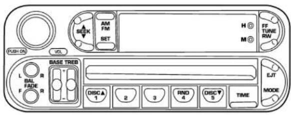
RBK Radio
Radio Operation
Power/Volume Control
Press the ON/VOL control to turn the radio on. Turn the volume control clockwise to increase the volume.
NOTE: Power to operate the radio is supplied through the ignition switch. It must be in the ON or ACC position to operate the radio.
Seek
Press and release the SEEK button to search for the next station in either the AM or FM mode. Press the top of the button to seek up and the bottom to seek down. The radio will remain tuned to the new station until you make another selection. Holding the button in will bypass stations without stopping until you release it.
Tune
Press the TUNE control up or down to increase or decrease the frequency. If you press and hold the button,
154 UNDERSTANDING YOUR INSTRUMENT PANEL
the radio will continue to tune until you release the button. The frequency will be displayed and continuously updated while the button is pressed.
Balance
The Balance control adjusts the left-to-right speaker balance. Press the BAL button in and it will pop out. Adjust the balance and push the button back in.
Fade
The Fade control provides for balance between the front and rear speakers. Press the FADE button in and it will pop out. Adjust the balance and push the button back in.
Bass and Treble Tone Control
The tone controls consist of 2 separate bands. The bass band is on the left, and the treble band is on the right. Each band is adjusted by a slider control with a detent at the mid-position. Moving the control up or down increases or decreases amplification of that band. The mid position provides a balanced output.
AM/FM Selection
Press the AM/FM button to change from AM to FM. The operating mode will be displayed next to the station frequency. The display will show ST when a stereo station is received.
To Set The Radio Push-Button Memory
When you are receiving a station that you wish to commit to push-button memory, press the SET button. SET 1 will show in the display window. Select the "1-5" button you wish to lock onto this station and press and release that button. If a button is not selected within 5 seconds after pressing the SET button, the station will continue to play but will not be locked into push-button memory.
You may add a second station to each push-button by repeating the above procedure with this exception: Press the SET button twice and SET 2 will show in the display window. Each button can be set for SET 1 and SET 2 in
both AM and FM. This allows a total of 10 AM and 10 FM stations to be locked into push-button memory. The stations stored in SET 2 memory can be selected by pressing the push-button twice. Every time a preset button is used a corresponding button number will be displayed.
Time
Press the TIME button to change the display between radio frequency and time.
General Information
This radio complies with Part 15 of FCC rules and with RSS-210 of Industry Canada. Operation is subject to the following conditions:
- This device may not cause harmful interference,
- This device must accept any interference received, including interference that may cause undesired operation.
NOTE: Changes or modifications not expressively approved by the party responsible for compliance could void the user's authority to operate the equipment.
CD Player Operation
NOTE: The ignition switch must be in the ON or ACC position and the volume control ON before the CD player will operate.
Inserting The Compact Disc
CAUTION!
This CD player will accept 4 34 inch (12 cm) discs only. The use of other sized discs may damage the CD player mechanism.
You may either insert or eject a disc with the radio OFF.
156 UNDERSTANDING YOUR INSTRUMENT PANEL
If you insert a disc with the ignition ON and the radio OFF, the display will show the time of day.
If the power is ON, the unit will switch from radio to CD mode and begin to play when you insert the disc. The display will show the track number and index time in minutes and seconds. Play will begin at the start of track one.
Seek
Press the top of the SEEK button for the next selection on the CD. Press the bottom of the button to return to the beginning of the current selection, or return to the beginning of the previous selection if the CD is within the first second of the current selection.
EJT — Eject
Press the EJT button and the disc will unload and move to the entrance for easy removal. The unit will switch to the radio mode.
If you do not remove the disc within 15 seconds, it will be reloaded. The unit will continue in radio mode.
The disc can be ejected with the radio and ignition OFF.
FF/TUNE/RW
Press FF (Fast Forward) and the CD player will begin to fast forward until FF is released. The RW (Reverse) button works in a similar manner.
Random Play — RND/Program Button 4
Press the RND (button 4) button while the CD is playing to activate Random Play. This feature plays the tracks on the selected disc in random order to provide an interesting change of pace.
Press the SEEK button to move to the next randomly selected track.
Press the RND (button 4) button a second time to stop Random Play.
Mode
Press the MODE button repeatedly to select between the CD player, the optional remote CD changer and the Satellite Radio (if equipped). When Satellite Radio (if equipped) is selected "SA" will appear in your radio display.
A CD or tape may remain in the player while in the Satellite mode.
Time
Press the TIME button to change the display from elapsed CD playing time to time of day.
CD Changer Control Capability — If Equipped
This radio is compatible with a remote mounted CD changer available through Mopar Accessories. The following instructions are for the radio controls that operate this CD changer.
Mode Button
To activate the CD changer, press the MODE button until CD information appears on the display.
Push-Button
While the CD changer is playing, press the NUMBER 1 push-button or the NUMBER 5 push-button to select a disc numbered higher or lower than the one currently being played.
Seek Button
Press the SEEK up or down to select another track on the same disc. A SEEK symbol will appear on the display.
Fast Forward And Rewind Buttons
Press and hold the FF button for fast forward. Press and hold the RW button for fast reverse.
The audio output can be heard when fast forward and fast reverse are activated.
158 UNDERSTANDING YOUR INSTRUMENT PANEL
Random Play (RND)
Press the Random button to play the tracks on the selected disc in random order for an interesting change of pace.
Random can be cancelled by pressing the button a second time or by ejecting the CD from the changer.
CD Diagnostic Indicators
When driving over a very rough road, the CD player may skip momentarily. Skipping will not damage the disc or the player, and play will resume automatically.
As a safeguard and to protect your CD player, one of the following warning symbols may appear on your display.
A CD HOT symbol indicates the player is too hot.
CD HOT will pause the operation. Play can be resumed when the operating temperature is corrected or another MODE is selected.
An ERR symbol will appear on the display if the laser is unable to read the Disc data for the following reasons:
- Excessive vibration
• Disc inserted upside down - Damaged disc
• Water condensation on optics
Radio Display Messages
Your radio has been designed to display certain messages when a problem is detected with the CD player.
| DISPLAY | EXPLANATION | WHAT TO DO |
| E-01E-02E-06E-07 | Deadlock problemDisc eject problemElevator problemMagazine eject problem | See your dealer for serviceSee your dealer for serviceSee your dealer for serviceCheck that magazine is OK-if not see your dealer for service |
| No discs in magazine.Load discs in magazine.Player overheating.Allow to cool down. | ||
SALES CODE RBQ—AM/FM STEREO RADIO WITH 6 - DISC CD CHANGER
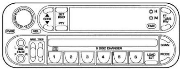
RBQ Radio
Radio Operation
Power/Volume Control
Press the PWR/VOL control to turn the radio on. Turn the volume control clockwise to increase the volume.
NOTE: Power to operate the radio is controlled by the ignition switch. It must be in the ON or ACC position to operate the radio.
Mode
Press the MODE button repeatedly to select between AM, FM, the CD changer and Sirius Satellite Radio ^™ (if equipped). The display will show ST when a stereo station is received.
To select Sirius Satellite Radio ^™ (if equipped), press the MODE button until the word SIRIUS appears. The following will be displayed in this order: After three seconds, the current channel name and number will be displayed for five seconds. The current program type and channel number will then be displayed for five seconds. The current channel name and number will then be displayed until an action occurs. CD's may remain in the player while in the Satellite Radio mode.
Seek
Press and release the SEEK button to search for the next station in either the AM or FM mode. Press the top of the button to seek up and the bottom to seek down. The radio will remain tuned to the new station until you make another selection. Holding the button in will bypass stations without stopping until you release it.
Tune
Press the TUNE control up or down to increase or decrease the frequency. If the button is pressed and held, the radio will continue to tune until the button is released. The frequency will be displayed and continuously updated while the button is pressed.
Balance — BAL
The Balance control adjusts the left-to-right speaker balance. Press the BAL button in and it will pop out. Adjust the balance and push the button back in.
Fade
The Fade control provides for balance between the front and rear speakers. Press the FADE button in and it will pop out. Adjust the balance and push the button back in.
Tone Control
The tone controls affect the Bass and Treble frequency bands. Each is controlled by a slider control with a detent at the mid position. Moving a control up or down increases or decreases amplification of the band. The mid position provides a balanced output.
To Set The Radio Push-Button Memory
When you are receiving a station that you wish to commit to push-button memory, press the SET RND button. SET 1 will show in the display window. Select the "1-6" button you wish to lock onto this station and press and release that button. If a button is not selected within 5 seconds after pressing the SET RND button, the station will continue to play but will not be locked into push-button memory.
You may add a second station to each push-button by repeating the above procedure with this exception: Press the SET button twice and SET 2 will show in the display window. Each button can be set for SET 1 and SET 2 in both AM and FM. This allows a total of 12 AM and 12 FM stations to be locked into push-button memory. The stations stored in SET 2 memory can be selected by pressing the corresponding push-button twice. Every time a preset button is used, a corresponding button number will be displayed.
Time Button
Press the TIME button to change the display between radio frequency and time.
162 UNDERSTANDING YOUR INSTRUMENT PANEL
General Information
This radio complies with Part 15 of FCC rules and with RSS-210 of Industry Canada. Operation is subject to the following conditions:
- This device may not cause harmful interference,
- This device must accept any interference received, including interference that may cause undesired operation.
NOTE: Changes or modifications not expressively approved by the party responsible for compliance could void the user's authority to operate the equipment.
CD Player Operation
NOTE: The ignition switch must be in the ON or ACC position and the Power / Volume control pushed ON before the CD player will operate.
Inserting The Compact Disc
CAUTION!
This CD player will accept 4 34 inch (12 cm) discs only. The use of other sized discs may damage the CD player mechanism.
You may either insert or eject a disc with the radio OFF. If you insert a disc with the ignition ON and the radio OFF, the display will show the time of day. If you insert a disc with the ignition OFF, the display will show the time of day for about 5 seconds, then go out.
If you insert a disc with the ignition ON and the radio ON, the unit will switch from radio to CD mode and begin to play when you insert the disc. The display will
show the disc number, the track number, and index time in minutes and seconds. Play will begin at the start of track 1.
LOAD/EJT — Load
Press the LOAD/ EJT button and the button with the corresponding number where the CD is being loaded. After the radio displays "load" insert the CD into the player.
Radio display will show "loading" when it is being loaded.
LOAD / EJT — Eject
Press the LOAD/ EJT button and the button with the corresponding number where the CD was loaded and the disc will unload and move to the entrance for easy removal.
Radio display will show "ejecting" when it is being ejected.
If you have ejected a disc and have not removed it within 15 seconds, it will be reloaded. If the CD is not removed, the radio will continue to play the non-removed CD. If the CD is removed and there are other CD's in the radio, the radio will play the next CD. If the CD is removed and there are no other CD's in the radio, the radio will return to the last selected AM or FM mode.
The disc can be ejected with the radio and ignition OFF.
Seek
Press the top of the SEEK button for the next selection on the CD. Press the bottom of the button to return to the beginning of the current selection, or return to the beginning of the previous selection if the CD is within the first second of the current selection.
Scan
Press the Scan button to scan through each track on the CD currently playing.
FF/TUNE/RW
Press FF (Fast Forward) and the CD player will begin to fast forward until FF is released. The RW (Reverse) button works in a similar manner.
Random Play — SET / RND
Press the RND button while the CD is playing to activate Random Play. This feature plays the tracks on the disc in random order to provide an interesting change of pace.
Press the SEEK button to move to the next randomly selected track.
Press TUNE FF to fast forward through the tracks. Press the FF button a second time to stop the fast forward feature. If TUNE RW is pressed, the current track will reverse to the beginning of the track and begin playing.
Press the SET / RND button a second time to stop Random Play.
PTY (Program Type) Button
Pressing this button once will turn on the PTY mode for 5 seconds. If no action is taken during the 5 second time out the PTY icon will turn off. Pressing the PTY button within 5 seconds will allow the program format type to be selected. Many radio stations do not currently broadcast PTY information.
Toggle the PTY button to select the following format types:
| Program Type Radio | Display |
| Adult Hits Adlt Hit | |
| Classical Classicl | |
| Classic Rock | Cls Rock |
| College | College |
| Country | Country |
| Emergency | ALERT! |
| Emergency Test | Test |
| Information Inform | |
| Jazz Jazz | |
| Foreign Language Language | |
| News News | |
| Nostalgia Nostalga | |
| Oldies Oldies | |
| Personality Persnity | |
| Public Public | |
| Rhythm and Blues R & B | |
| Religious Music Rel Musc | |
| Religious Talk Rel Talk | |
| Rock Rock | |
| Soft Soft | |
| Soft Rock Soft Rck | |
| Soft Rhythm and Blues | Soft R&B |
| Sports | Sports |
| Program Type Radio | Display |
| Talk | Talk |
| Top 40 | Top 40 |
| Weather | Weather |
By pressing the SEEK button when the PTY icon is displayed, the radio will be tuned to the next frequency station with the same selected PTY name. The PTY function only operates when in the FM mode.
The radio display will flash "SEEK" and the selected PTY program type when searching for the next PTY station. If no station is found with the selected PTY program type, the radio will return to the last station.
If a preset button is activated while in the PTY (Program Type) mode, the PTY mode will be exited and the radio will tune to the preset station.
166 UNDERSTANDING YOUR INSTRUMENT PANEL
By pressing the SCAN button when the PTY icon is displayed, the radio will stop at every PTY station on the band and list each corresponding program type in the radio display.
Time
Press the TIME button to change the display from elapsed CD playing time to time of day.
SALES CODE RB1—AM/FM STEREO RADIO WITH DVD/GPS NAVIGATION SYSTEM
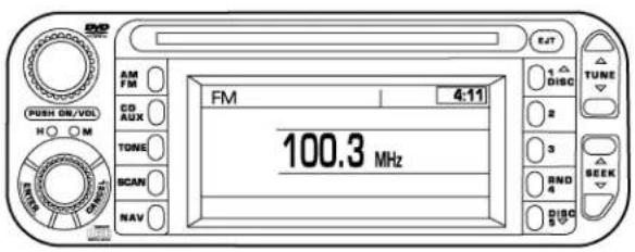
810774da
RB1 Radio
The navigation system provides maps, turn identification, selection menus and instructions for selecting a
variety of destinations and routes. Refer to your "Navigation User's Manual" for detailed operating instructions.
NOTE: If your vehicle is not equipped with the CD Changer option, you will not be able to use the Navigation system and the CD Player simultaneously. Always remove the Navigation DVD before inserting another disc.
CASSETTE TAPE AND PLAYER MAINTENANCE
To keep the cassette tapes and player in good condition, take the following precautions:
- Do not use cassette tapes longer than C-90; otherwise, sound quality and tape durability will be greatly diminished.
-
Keep the cassette tape in its case to protect from slackness and dust when it is not in use.
-
Keep the cassette tape away from direct sunlight, heat and magnetic fields such as the radio speakers.
- Before inserting a tape, make sure that the label is adhering flat to the cassette.
- A loose tape should be corrected before use. To rewind a loose tape, insert the eraser end of a pencil into the tape drive gear and twist the pencil in the required directions.
Maintain your cassette tape player. The head and capstan shaft in the cassette player can pick up dirt or tape deposits each time a cassette is played. The result of deposits on the capstan shaft may cause the tape to wrap around and become lodged in the tape transport. The other adverse condition is low or “muddy” sound from one or both channels, as if the treble tone control were turned all the way down. To prevent this, you should periodically clean the head with a commercially available WET cleaning cassette.
168 UNDERSTANDING YOUR INSTRUMENT PANEL
As preventive maintenance, clean the head about every 30 hours of use. If you wait until the head becomes very dirty (noticeably poor sound), it may not be possible to remove all deposits with a simple WET cleaning cassette.
CD/DVD DISC MAINTENANCE
To keep the CD/DVD discs in good condition, take the following precautions:
- Handle the disc by its edge; avoid touching the surface.
- If the disc is stained, clean the surface with a soft cloth, wiping from center to edge.
- Do not apply paper, paper CD labels, or tape to the disc; avoid scratching the disc.
- Do not use solvents such as benzine, thinner, cleaners, or antistatic sprays.
-
Store the disc in its case after playing.
-
Do not expose the disc to direct sunlight.
- Do not store the disc where temperatures may become too high.
Under certain conditions, the cellular phone being On in your vehicle can cause erratic or noisy performance from your radio. This condition may be lessened or eliminated by relocating the cellular phone antenna. This condition is not harmful to the radio. If your radio performance does not satisfactorily “clear” by the repositioning of the antenna, it is recommended that the radio volume be turned down or off during cellular phone operation.
CLIMATE CONTROLS
Air Conditioning
The Air Conditioning System allows you to balance the temperature, amount, and direction of air circulating throughout the vehicle. The controls are located on the instrument panel, above the radio.
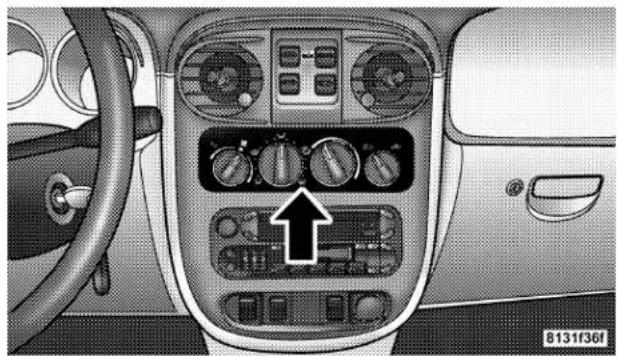
natural_image
Interior view of a car dashboard with air conditioners and a directional arrow indicator (no text or symbols)The air conditioning system of your vehicle contains R-134a, a refrigerant that does not deplete the ozone layer in the upper atmosphere.
The controls are as follows:
Fan and Air conditioning Control
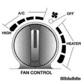
Use this control to regulate the amount of air forced through the system in any mode you select. The fan speeds to the left of the OFF position are for Air Conditioning. Choosing one of these speeds turns on the air conditioning compressor. The fan speed increases as you
move the control to the left from the OFF position.
NOTE: The air conditioning compressor will not engage until the engine has been running for about 10 seconds.
170 UNDERSTANDING YOUR INSTRUMENT PANEL
Fan speeds to the right of OFF are for heater or ventilation operation. The fan speed increases as you move the control to the right from the OFF position.
Mode Control (Air Direction)
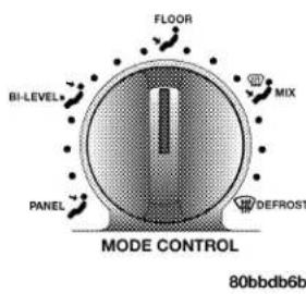
The mode control allows you to choose from several patterns of air distribution. You can select either a primary mode, as identified by the symbols, or a blend of two of these modes. The center point between modes gives an even blend of both modes. The closer the control is to a particular mode, the more air distribution you receive from that mode.
Panel
Air is directed through the outlets in the instrument panel. These outlets can be adjusted to direct air flow.
Bi-Level
Air is directed through the panel and floor outlets.
NOTE: There is a difference in temperature between the upper and lower outlets for added comfort. The warmer air goes to the floor outlets. This feature gives improved comfort during sunny but cool conditions.
Floor
Air is directed through the floor outlets and side window demist outlets with a small amount through the defrost outlet.
Mix

Air is directed through the floor, defrost and side window demist outlets. This setting works best in cold or snowy conditions that require extra heat at indshield. This setting is good for maintaining port while reducing moisture on the windshield.
Defrost

Air is directed through the windshield and side window demist outlets. Use this mode with maxi-fan and temperature settings for best windshield side window defrosting.
NOTE: The air conditioning compressor operates in both Mix and Defrost or a blend of these modes even if the fan switch is not in the A/C position. This dehumidifies the air to help dry the windshield. To improve fuel economy, use these modes only when necessary.
Air Outlets
The airflow from each of the instrument panel outlets can be adjusted for direction and turned on or off to control air flow.
A knob attached in the center of each instrument panel outlet is used to adjust the airflow direction, and a knob on the outer edge of each instrument panel outlet grille opens or closes a shutter to turn airflow on or off through that outlet.
NOTE: For maximum airflow to the rear seat passengers, the center instrument panel outlets can be aimed, so that the left center outlet is directed toward the right rear passenger and the right center outlet is directed toward the left rear passenger.
172 UNDERSTANDING YOUR INSTRUMENT PANEL
Temperature Control
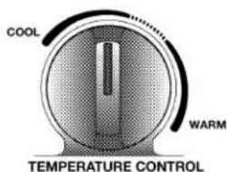
Use this control to regulate the temperature of the air inside the passenger compartment. The blue area of the scale indicates cooler temperatures while the red area indicates warmer temperatures.
80bbdb6c
NOTE: If your air conditioning performance seems lower than expected, check the front of the A/C condenser: located in front of the radiator, for an accumulation of dirt or insects. Clean with a gentle water spray from behind the radiator and through the condenser. Fabric front fascia protectors may reduce air flow to the condenser, reducing air conditioning performance.
Circulation Control
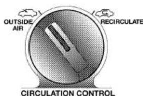
80bbdb6d
Use this control to choose between outside air intake or recirculation of the air inside the vehicle. Only use the recirculate mode to temporarily block out any outside odors, smoke, or dust and to cool the interior rapidly upon initial start up in very hot or humid weather.
This control only operates in the Outside Air and Recirculate modes; there is no in between position. Do not place the control between these positions.
NOTE: Continuous use of the recirculate mode may make the inside air stuffy and window fogging may occur. Extended use of this mode is not recommended.
In cold or damp weather, the use of the Recirculate position will cause windows to fog on the inside because of moisture build up inside the vehicle. For maximum defogging, select the Outside Air position.
If the mode control is in the range between Mix and Defrost and you choose the recirculate mode, the mode control knob will automatically move to the left of the Mix position.
NOTE: If you choose Defrost mode and the Circulation control is in the recirculate Mode, the system will automatically switch to the Outside Air mode and the knob will move to that position.
Operating Tips
| WEATHER | CONTROL SETTINGS |
HOT WEATHERAND VEHICLE INTERIOR IS VERY HOT  | Open the windows, start the vehicle, and place the Circulation control at [IMAGE].Set the Fan control to the high A/C position (full counterclockwise) position. Set the Mode control at or between [IMAGE] and [IMAGE]. Set the temperature control to full cool.After the hot air is flushed from the vehicle, turn the Circulation control to [IMAGE] and roll up the windows. Once you are comfortable, place the Circulation control at [IMAGE] and adjust the temperature control for comfort. |
WARM WEATHER  | Set the Circulation control to [IMAGE].If it's sunny, set the Mode control at or near [IMAGE] and turn the air conditioning on. If it's cloudy or dark, set the Mode control at or near [IMAGE]. |
COOL OR COLD=IMID CONDITIONS [HWYS] [HWYS] | Set the Circulation control to [IMAGE].If it's sunny, set the Mode control at or between [IMAGE] and [IMAGE] then turn the air conditioning on. If it's cloudy or dark, set the Mode control at or near [IMAGE] and turn the air conditioning on. |
COL D DRYCOI [IMAGE] [IMAGE] | Set the Circulation control to [IMAGE].Set the Mode control at or near [IMAGE]. If it is sunny, you may want more upper air. In this case, set the Mode control at or between [IMAGE] and [IMAGE]. In very cold weather, if you need extra heat at the windshield, set the Mode control at or near the [IMAGE]. |
Window Fogging
Vehicle side windows tend to fog on the inside in mild rainy or humid weather. To clear the windows, use the A/C, PANEL and blower controls. Direct the panel outlets toward the side windows. Do not use recirculate without A/C for long periods as fogging may occur.
Interior fogging on the windshield can be quickly removed by using the defrost position.
If the fogging problem persists, clean the inside window surfaces. The cause of undue fogging may be dirt collecting on the inside surface of the glass.
NOTE: In cold weather, the use of the recirculate position will cause windows to fog on the inside because of moisture build up inside the vehicle. For maximum defogging, use the Outside Air position.
Summer Operation
Air conditioned vehicles must be protected with a high-quality antifreeze coolant to provide proper corrosion protection and to raise the boiling point of the coolant for protection against overheating. A 50% concentration is recommended.
Outside Air Intake
When operating the system during the winter months, make sure the air intake, directly in front of the windshield, is free of ice, slush, snow or other obstructions such as leaves. Leaves collected in the air-intake plenum may reduce air flow and plug the plenum water drains.
The blower air will heat faster in cold weather if you use only a low blower speed for the first few minutes of vehicle operation.
176 UNDERSTANDING YOUR INSTRUMENT PANEL
Side Window Demisters
A side window demister outlet is at each end of the instrument panel. These nonadjustable outlets direct air toward the side windows when the system is in either the FLOOR, MIX, or DEFROST mode. The air is directed at the area of the windows through which you view the outside mirrors.
Electric Rear Window Defroster

The push-button is located at the center of the instrument panel, below the radio. Press this button to turn on the rear window defroster, and the optional electric remote control heated mirrors. An amber light shows that the defroster is on.
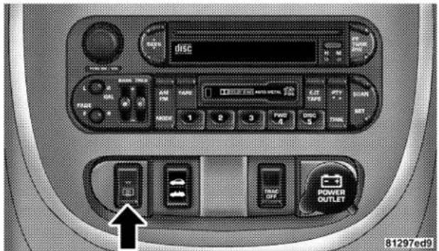
Rear Defroster Switch
NOTE: The defroster turns off automatically after 10 minutes of operation. Each following activation of the defroster will last for five minutes.
CAUTION!
To avoid damaging the electrical conductors, do not use scrapers, sharp instruments, or abrasive window cleaners on the interior surface of the rear window. Labels can be peeled off after soaking with warm water.
STARTING AND OPERATING
CONTENTS
■Starting Procedures....182
□Automatic Transaxle....182
□Manual Transaxle....182
□Normal Starting....182
□Extremely Cold Weather (Below -20^ Or -29^ ) 183
□If Engine Fails To Start....183
□After Starting....184
□ Turbocharger "Cool Down" .....184
■ Automatic Transaxle — If Equipped .....185
□Brake/Transmission Interlock System ..... 1 8 6
□Automatic Transaxle Ignition Interlock System....186
□ Four Speed Automatic Transaxle .....186
□Reset Mode 187
□Gear Ranges For Four Speed Automatic Transaxle....187
■ AutoStick — If Equipped .....190
□AutoStick Operation....190
180 STARTING AND OPERATING
□AutoStick General Information....190
■Manual Transaxle Operation....191
□ 2.4 Liter Turbo— If Equipped .....193
□Recommended Shift Speeds....194
□Downshifting....194
■Parking Brake....195
■Brake System....197
□Anti-Lock Brake System (ABS) — If Equipped . 198
■Power Assisted Steering....199
■ Traction Control — If Equipped .....200
■Tire Safety Information....201
□Tire Markings 201
□Tire Identification Number (TIN)....205
□Tire Loading And Tire Pressure 206
■ Tires—General Information .....210
□Tire Pressure....210
□Tire Inflation Pressures 211
□ Radial-Ply Tires 214
□ Compact Spare Tire — If Equipped .....214
□Limited Use Spare — If Equipped .....215
□Tire Spinning 216
□Tread Wear Indicators 216
□ Replacement Tires .....217
□ Alignment And Balance .....218
■Tire Chains 219
■Snow Tires 219
STARTING AND OPERATING 181
■Tire Rotation Recommendations....2 2 0
■Fuel Requirements....2 2 1
☐2.4L Standard Engine And 2.4L Standard Turbo Engine....2 2 1
□2.4L High Output Turbo Engine ..... 2 2 1
□Reformulated Gasoline....2 2 2
□Gasoline/Oxygenate Blends....2 2 2
□MMT In Gasoline....2 2 3
□Materials Added To Fuel....2 2 3
□Fuel System Cautions 2 2 3
□Carbon Monoxide Warnings....2 2 4
■Adding Fuel 2 2 5
□Fuel Filler Cap (Gas Cap) 2 2 5
■Vehicle Loading....2 2 7
■Trailer Towing....2 2 7,
□Warranty 228
182 STARTING AND OPERATING
STARTING PROCEDURES
Before starting your vehicle, adjust your seat, adjust both inside and outside mirrors, and fasten your seat belts.
CAUTION!
Long periods of engine idling, especially at high engine speeds can cause excessive exhaust temperatures which can damage your vehicle. Do not leave your vehicle unattended with the engine running.
WARNING!
Do not leave children or animals inside parked vehicles in hot weather. Interior heat build up may cause serious injury or death.
Automatic Transaxle
The gear selector must be in the NEUTRAL or PARK position before you can start the engine. Apply the brakes before shifting to any driving gear.
NOTE: You must press the brake pedal before shifting out of Park.
Manual Transaxle
Before starting the engine fully apply the parking brake, press the clutch pedal to the floor and place the gear selector in NEUTRAL.
NOTE: The engine will not start unless the clutch pedal is pressed to the floor.
Normal Starting
Normal Starting of either a cold or a warm engine does not require pumping or depressing the accelerator pedal. Simply turn the ignition switch to the "START" position and release when the engine starts. If the engine has not
started within 3 seconds, slightly depress the accelerator pedal while continuing to crank. If the engine fails to start within 15 seconds, turn the ignition switch to the "OFF" position, wait 10 to 15 seconds, then repeat the normal starting procedure.
WARNING!
Do not attempt to push or tow your vehicle to get it started. Vehicles equipped with an automatic transaxle cannot be started this way. Unburned fuel could enter the catalytic converter and once the engine has started, ignite and damage the converter and vehicle. If the vehicle has a discharged battery, booster cables may be used to obtain a start from another vehicle. This type of start can be dangerous if done improperly, so follow the procedure carefully. See section 6 of this manual for jump starting instructions.
Extremely Cold Weather (below -20^ F or -29^ C)
To insure reliable starting at these temperatures, use of an externally powered electric engine block heater (available from your dealer) is recommended.
If Engine Fails to Start
If the engine fails to start after you have followed the "NORMAL STARTING" procedure, it may be flooded. Push the accelerator pedal all the way to the floor and hold it there. Crank the engine for no more than 15 seconds. This should clear any excess fuel in case the engine is flooded. Leave the ignition key in the ON position, release the accelerator pedal and repeat the "NORMAL STARTING" procedure.
184 STARTING AND OPERATING
WARNING!
Never pour fuel or other flammable liquid into the throttle body air inlet opening in an attempt to start the vehicle. This could result in flash fire causing serious personal injury.
CAUTION!
To prevent damage to the starter, do not crank the engine for more than 15 seconds at a time. Wait 10 to 15 seconds before trying again.
After Starting
The idle speed will automatically decrease as the engine warms up.
Turbocharger "Cool Down"
NOTE: Letting the engine idle after severe operation allows the turbine housing to cool to normal operating temperature.
The following chart should be used as a guide in determining the amount of engine idle time required to sufficiently cool down the turbocharger before shut down, depending upon the type of driving and the amount of cargo.
| TURBOCHARGER "COOL DOWN"CHART | |
| Driving Conditions Idle Time (in minutes) Before Shut Down | |
| Normal Driving Not required. | |
| Aggressive Driving or Heavily Loaded 3 | |
| Trailer Tow 5 | |
AUTOMATIC TRANSAXLE — IF EQUIPPED
| CAUTION! |
| Damage to the transaxle may occur if the following precautions are not observed: |
- Shift into PARK only after the vehicle has come to a complete stop.
- Shift into or out of REVERSE only after the vehicle has come to a complete stop and the engine is at idle speed.
- Do not shift from REVERSE, PARK, or NEUTRAL into any forward gear when the engine is above idle speed.
- Before shifting into any gear, make sure your foot is firmly on the brake pedal.
NOTE: You MUST press and hold the brake pedal down while shifting out of Park.
WARNING!
It is dangerous to shift the selector lever out of "P" or "N" if the engine speed is higher than idle speed. If your foot is not firmly on the brake pedal, the vehicle could accelerate quickly forward or in reverse. You could lose control of the vehicle and hit someone or something. Only shift into gear when the engine is idling normally and when your right foot is firmly on the brake pedal.
Brake/Transmission Interlock System
This system prevents you from moving the gear shift out of Park and into any gear unless the brake pedal is pressed. This system is active only while the ignition switch is in the ON positions. Always depress the brake pedal first, before moving the gear selector out of PARK.
Automatic Transaxle Ignition Interlock System
This system prevents the key from being removed unless the shift lever is in PARK and the shift knob push button is out. It also prevents shifting out of PARK unless the key is in the OFF or ON positions.
NOTE: If a malfunction occurs, the system will trap the key in the ignition cylinder to warn you that this safety feature is inoperable. The engine can be started and stopped but the key cannot be removed until you obtain service.
Four Speed Automatic Transaxle
The electronically controlled transaxle provides a precise shift schedule. The transaxle electronics are self calibrating; therefore, the first few shifts on a new vehicle may be somewhat abrupt. This is a normal condition, and precision shifts will develop within a few shift cycles.
STARTING AND OPERATING 187
Reset Mode
The transaxle is monitored electronically for abnormal conditions. If a condition is detected that could cause damage, the transaxle shifts automatically into second gear. The transaxle remains in second gear despite the forward gear selected. Park (P), Reverse (R), and Neutral (N) will continue to operate. This second gear limp-in feature allows the vehicle to be driven to a dealer for service without damaging the transaxle.
In the event that the problem has been momentary, the transaxle can be reset to regain all forward gears.
Stop the vehicle and shift into Park (P).
Turn the Key to OFF then restart the engine.
Shift into D and resume driving.
NOTE: Even if the transaxle can be reset, it is recommended that you visit a dealer at your earliest possible convenience. Your dealer has diagnostic equipment to determine if the problem could recur.
If the transaxle cannot be reset, dealer service is required.
Gear Ranges For Four Speed Automatic
Transaxle
DO NOT race the engine when shifting from PARK or NEUTRAL positions into another gear range.
"P" Park
Supplements the parking brake by locking the transmission. The engine can be started in this range. Never use P (Park) while the vehicle is in motion. Apply the parking brake when leaving the vehicle in this range. Always apply the parking brake first, and then place the selector in P (Park) position.
WARNING!
Unintended movement of a vehicle could injure those in and near the vehicle. As with all vehicles, you should never exit a vehicle while the engine is running. Before exiting a vehicle, you should always shift the vehicle into P (Park), remove the key from the ignition, and apply the parking brake. Once the key is removed from the ignition, the transmission shift lever is locked in the P (Park) position, securing the vehicle against unwanted movement. Furthermore, you should never leave children unattended inside a vehicle.
The following indicators should be used to ensure that you have engaged the transmission shift lever into the P (Park) position:
- When shifting into P (Park), depress the button on the shift lever and firmly move the lever all the way forward until it stops.
- Look at the shift indicator window on the console to ensure it is in the P (Park) position.
- When engaged in P (Park), you will not be able to move the shifter rearward without depressing the shift lever button.
CAUTION!
Before moving the shift lever out of P (Park), you must turn the ignition from LOCK to ON so the steering wheel and shift lever are released. Otherwise, damage to the steering column or shifter could result.
"R" Reverse
Shift into this range only after the vehicle has come to a complete stop.
"N" Neutral
Engine may be started in this range.
"D" Overdrive
This range should be used for most city and highway driving. It provides smoothest up shifts and down shifts and best fuel economy.
When frequent transaxle shifting occurs while using the Overdrive range, such as when operating the vehicle under heavy loading conditions (in hilly terrain, traveling into strong head winds, or while towing trailers), use the "3" range.
"3" Drive
This range eliminates shifts into Overdrive. The transaxle will operate normally in first and second while in this range.
NOTE: Using the "3" range while operating the vehicle under heavy operating conditions will improve performance, fuel economy, and extend transaxle life by reducing excessive shifting and heat build up.
Use the "3" range when descending steep grades to prevent brake system distress.
"1" Low
This range should be used for maximum engine braking when descending steep grades. In this range, up shifts will occur only to prevent engine over speed while down shifts from 2nd to first will occur as early as possible.
190 STARTING AND OPERATING
AUTOSTICK — IF EQUIPPED
Autostick is a driver-interactive transmission that offers manual gear shifting capability to provide you with more control. Autostick allows you to maximize engine braking, eliminate undesirable upshifts and downshifts, and improve overall vehicle performance. This system can also provide you with more control during passing, city driving, cold slippery conditions, mountain driving, trailer towing, and many other situations.
Autostick Operation
The Autostick position is just below the Overdrive position and is identified by the word "AUTOSTICK". When you place the shift lever in the Autostick position, it can be moved from side to side. Moving the lever to the left (-) triggers a downshift and to the right (+) an upshift. The gear position will be shown in the transmission gear display, located in the instrument cluster.
You can shift in or out of the autostick mode at any time without taking your foot off the accelerator pedal. If you choose the Overdrive mode, the transmission will operate automatically; shifting between the four available gears. When you wish to engage autostick, simply move the shift lever to the AUTOSTICK position. The transmission will remain in the current gear until an upshift or downshift is chosen.
Move the lever back to the Overdrive position to shift out of the Autostick mode.
Autostick General Information
- The transmission will automatically upshift from first to second gear and from second to third gear when engine speed reaches about 6300 RPM.
- Downshifts from third to second gear above 74 mph (119 km/h) and from second to first gear above 41 mph (66 km/h) will be ignored.
- You can start out in first, second, or third gear. Shifting into fourth gear can occur only after vehicle speed reaches 15 mph (24 km/h).
- The transmission will automatically downshift to first gear when coming to a stop.
- Starting out in third gear is helpful in snowy or icy conditions.
-
While in the Autostick mode, Speed Control will only function in third or fourth gear.
Downshifting out of third gear will turn off the speed control. -
If the system detects powertrain overheating, the transmission will revert to the automatic shift mode and remain in that mode until the powertrain cools off.
- If the system detects a problem it will disable the Autostick mode and the transmission will return to the automatic mode until the problem is corrected.
NOTE: The parking brake should be engaged and the gear selector placed in REVERSE before leaving the vehicle, especially on an incline.
192 STARTING AND OPERATING
Fully depress the clutch pedal before you shift gears. As you release the clutch pedal, lightly depress the accelerator pedal.
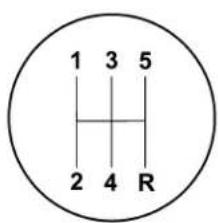
80f7bc4b
Use each gear in numerical order - do not skip a gear. Be sure the transaxle is in FIRST gear, (not THIRD), when starting from a standing position. Damage to the clutch can result from starting in THIRD.
For most city driving you will find it easier to use only the lower gears. For steady highway driving with light accelerations, 5th gear is recommended.
Never drive with your foot resting on the clutch pedal, or try to hold the vehicle on a hill with the clutch pedal partially engaged. This will cause abnormal wear on the clutch.
Never shift into REVERSE until the vehicle has come to a complete stop.
NOTE: During cold weather, until the transaxle lubricant is warm, you may experience slightly higher shift efforts. This is normal and not harmful to the transaxle.
2.4 Liter Turbo—If Equipped
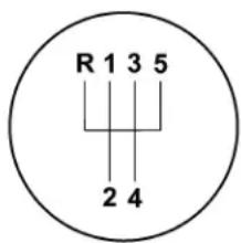
80f7bc54
The neutral position of the shift lever is located between THIRD and FOURTH gear. This is the position the shifter lever will return to automatically when neutral is selected. When shifting into FIFTH gear, be sure to press the shifter lever all the way to the right to avoid accidentally selecting THIRD gear. Also, use care when selecting FIRST gear to avoid accidentally selecting REVERSE.
When moving the shifter lever into REVERSE press the lever to the left until the resistance is overcome. When the ignition switch is in the ON position, a chime will sound to confirm that reverse has been selected and the backup lights will illuminate.
NOTE: Listen for the audible chime to confirm RE-VERSE gear is properly selected. Never shift into RE-VERSE until the vehicle has come to a complete stop.
Recommended Shift Speeds
To use your manual transaxle for optimal fuel economy, it should be upshifted as listed in table 1.
| TABLE 1-MANUAL TRANSAXLE NORMAL ACCELERATION AND CRUISE SHIFT SPEEDS IN mph (km/h) | |||||
| EN-GINE SIZE | MODE 1 to 2 2 | to 3 3 | to 4 4 | to 5 | |
| 2.4L Turbo | Accel 15 (24) 25 | (40) 40 (65) | 45 (72) | ||
| Cruise 15 (24) 25 | (40) 42 (68) | 45 (72) | |||
| 2.4L Non-Turbo | Accel 15 (24) 25 | (40) 33 (53) | 44 (70) | ||
| Cruise 16 (26) 20 | (32) 28 (45) | 38 (61) | |||
For improved performance, your manual transaxle may be upshifted up to the maximum speeds listed in table 2 (within legal speed limits).
| TABLE 2-MANUAL TRANSAXLE MAXIMUM PERFORMANCE SHIFT SPEEDS IN mph (km/h) | ||||
| ENGINE SIZE | 1 to 2 | 2 to 3 | 3 to 4 | 4 to 5 |
| 2.4L | 30(48) | 60(97) | 85(136) | 115(185) |
If you exceed these speeds, you may notice the engine cut in and out. This is caused by an electronic limiter in the engine computer. The engine will run normally when you reduce engine speed.
Downshifting
Proper downshifting will improve fuel economy and prolong engine life.
CAUTION!
If you skip more than one gear while downshifting or downshift at too high an engine speed, you could damage the engine, transmission, or clutch.
To maintain a safe speed and prolong brake life, shift down to 2nd or 1st when descending a steep grade.
When turning a corner, or driving up a steep grade, downshift early so that the engine will not be overburdened.
PARKING BRAKE

When the parking brake is applied with the ignition on, the Brake Light in the instrument cluster will come on.
NOTE: This light only shows that the parking brake is on. It does not show the degree of brake application.
If the parking brake is applied while the vehicle is moving, a chime will sound to alert the driver. The chime will sound up to 10 times or until the vehicle has returned to a stop.
Before leaving the vehicle, make sure that the parking brake is set. To set the parking brake, pull up firmly on the lever. Also place the gear selector in the Park position (automatic transaxle) or Reverse (manual transaxle). To release the parking brake, apply the brake pedal, pull up slightly on the lever, then depress the button on the end of the lever and push the lever fully down toward the floor.
196 STARTING AND OPERATING
NOTE: The parking brake lever will not release unless the lever is pulled up slightly past its applied position.
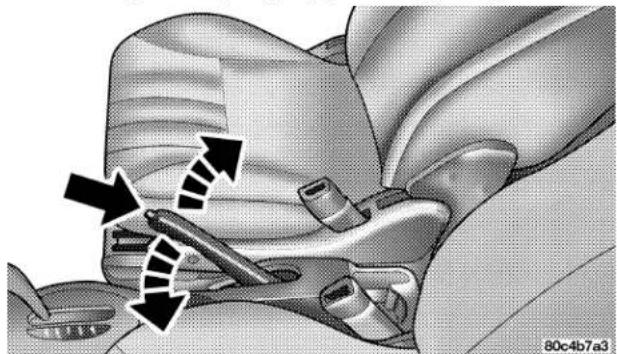
natural_image
Close-up of a car seatbelt mechanism with arrows indicating movement or force (no text or symbols present)Parking Brake Lever
When parking on a hill, it is important to set the parking brake before placing the gear selector in Park, otherwise the load on the automatic transaxle locking mechanism may make it difficult to move the selector out of Park. As an added precaution, turn the front wheels toward the curb on a downhill grade and away from the curb on a uphill grade.
You should always apply the parking brake before leaving the vehicle.
WARNING!
- Leaving children in a vehicle unattended is dangerous for a number of reasons. A child or others could be injured. Children should be warned not to touch the parking brake or the gear selector. Don't leave the keys in the ignition. A child could operate power windows, other controls, or move the vehicle.
- Be sure the parking brake is fully disengaged before driving; failure to do so can lead to brake failure and an accident.
BRAKE SYSTEM
Your vehicle is equipped with power assisted brakes as standard equipment. In the event power assist is lost for any reason (for example, repeated brake applications with the engine off), the brakes will still function. However, the effort required to brake the vehicle will be much greater than that required with the power system operating.
WARNING!
Riding the brakes can lead to brake failure and possibly an accident. Driving with your foot resting or riding on the brake pedal can result in abnormally high brake temperatures, excessive lining wear, and possible brake damage. You wouldn't have your full braking capacity in an emergency.
198 STARTING AND OPERATING
If either of the two hydraulic systems lose normal capability, the remaining system will still function with some loss of overall braking effectiveness. This will be evident by increased pedal travel during application and greater pedal force required to slow or stop. In addition, if the malfunction is caused by an internal leak, as the brake fluid in the master cylinder drops, the brake warning indicator will light.
Anti-Lock Brake System (ABS) — If Equipped
The ABS gives increased vehicle stability and brake performance under most braking conditions. The system automatically “pumps” the brakes during severe braking conditions to prevent wheel lock up.
All vehicle wheels and tires must be the same size and tires must be properly inflated to produce accurate signals for the computer. However, the system will compensate when the compact spare is in use.
During stops where ABS is activated, a vibration of the brake pedal may be felt and associated system noises may be heard.
NOTE: Pumping of the brake pedal will diminish the effectiveness of Anti-lock brakes and may lead to an accident. Pumping makes the stopping distance longer. Just press firmly on your brake pedal when you need to slow down or stop.
WARNING!
- Anti-lock system (ABS) cannot prevent the natural laws of physics from acting on the vehicle, nor can it increase braking or steering efficiency beyond that afforded by the condition of the vehicle brakes and tires or the traction afforded.
- The ABS cannot prevent accidents, including those resulting from excessive speed in turns, following another vehicle too closely, or hydroplaning. Only a safe, attentive, and skillful driver can prevent accidents.
- The capabilities of an ABS equipped vehicle must never be exploited in a reckless or dangerous manner which could jeopardize the user's safety or the safety of others.
POWER ASSISTED STEERING
The power assisted steering system of your vehicle provides mechanical steering capability in the event power assist is lost.
If for some reason the hydraulic pressure is interrupted, it will still be possible to steer your vehicle. Under these conditions you will observe a substantial increase in steering effort.
200 STARTING AND OPERATING
TRACTION CONTROL — IF EQUIPPED
The Traction Control System will improve acceleration and steering on slippery surfaces by reducing tire spin. The system reduces wheel slip and maintains traction at the driving (front) wheels by engaging the brake on the wheel that is losing traction. When this occurs the TRAC indicator light located above the instrument cluster odometer will flash. The system operates at speeds below 40 mph (64 km/h).
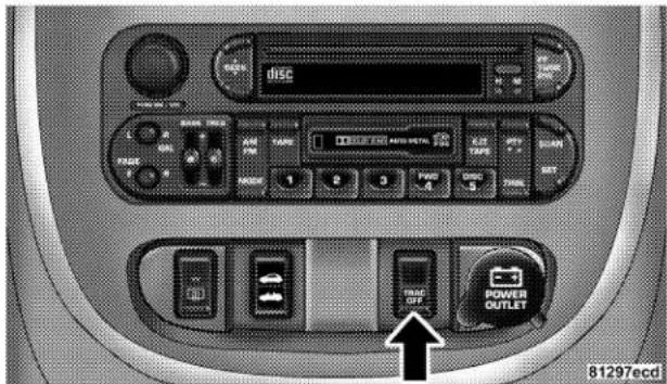
Traction Control Switch
A push-button at the center of the instrument panel, below the radio, turns the Traction Control System ON or OFF.
The system is always in the "ON" mode unless:
- The TRAC OFF switch has been used to turn the system off;
• There is a Anti-Lock Brake System malfunction;
• There is a Traction Control System malfunction; - The system has been automatically deactivated to prevent damage to the brake system due to overheated brake temperatures.
NOTE: Extended heavy use of Traction Control may cause the system to deactivate and turn on the TRAC OFF Light located in the instrument cluster.
This is to prevent overheating of the brake system and is a normal condition. The system will remain disabled for about 4 minutes until the brakes have cooled. The system will automatically reactivate and turn off the TRAC OFF light.
If your vehicle becomes stuck in mud, ice, or snow, turn the Traction Control System Off before attempting to "rock" the vehicle free.
TIRE SAFETY INFORMATION
Tire Markings
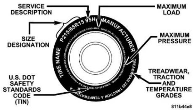
202 STARTING AND OPERATING
NOTE:
- P(Passenger)-Metric tire sizing is based on U.S. design standards. P-Metric tires have the letter "P" molded into the sidewall preceding the size designation. Example: P215/65R15 95H.
- European Metric tire sizing is based on European design standards. Tires designed to this standard have the tire size molded into the sidewall beginning with the section width. The letter "P" is absent from this tire size designation. Example: 215/65R15 96H
- LT(Light Truck)-Metric tire sizing is based on U.S. design standards. The size designation for LT-Metric
tires is the same as for P-Metric tires except for the letters "LT" that are molded into the sidewall preceding the size designation. Example: LT235/85R16.
- Temporary Spare tires are high pressure compact spares designed for temporary emergency use only. Tires designed to this standard have the letter "T" molded into the sidewall preceding the size designation. Example: T145/80D18 103M.
- High Flotation tire sizing is based on U.S. design standards and begins with the tire diameter molded into the sidewall. Example: 31x10.5 R15 LT.
Tire Sizing Chart
| EXAMPLE: |
| Size Designation: P = Passenger car tire size based on U.S. design standards"....blank...." = Passenger car tire based on European design standardsLT = Light Truck tire based on U.S. design standardsT = Temporary Spare tire31 = Overall Diameter in Inches (in) |
| 215 = Section Width in Milimeters (mm) |
| 65 = Aspect Ratio in Percent (%)—Ratio of section height to section width of tire.10.5 = Section Width in Inches (in) |
| R = Construction Code—"R"means Radial Construction.—"D"means Diagonal or Bias Construction. |
| 15 = Rim Diameter in Inches (in) |
204 STARTING AND OPERATING
| EXAMPLE: |
| Service Description: |
| 95 = Load Index—A numerical code associated with the maximum load a tire can carry. |
| H = Speed Symbol—A symbol indicating the range of speeds at which a tire can carry a load corresponding to its load index under certain operating conditions.—The maximum speed corresponding to the Speed Symbol should only be achieved under specified operating conditions. (ie. tire pressure, vehicle loading, road conditions and posted speed limits). |
| Load Identification: |
| "...blank..." = Absence of any text on sidewall of the tire indicates a Standard Load (SL) Tire |
| Extra Load (XL) = Extra Load (or Reinforced) Tire |
| Light Load = Light Load Tire |
| C,D,E = Load range associated with the maximum load a tire can carry at a specified pressure |
| Maximum Load — Maximum Load indicates the maximum load this tire is designed to carry. |
| Maximum Pressure — Maximum Pressure indicates the maximum permissible cold tire inflation pressure for this tire. |
Tire Identification Number (TIN)
The TIN may be found on one or both sides of the tire however the date code may only be on one side. Tires with white sidewalls will have the full TIN including date code located on the white sidewall side of the tire.
Look for the TIN on the outboard side of black sidewall tires as mounted on the vehicle. If the TIN is not found on the outboard side then you will find it on the inboard side of the tire.
| EXAMPLE: |
| DOT MA L9 ABCD 0301 |
| DOT = Department of Transportation—This symbol certifies that the tire is in compliance with the U.S. Department of Transportation tire safety standards, and is approved for highway use. |
| MA = Code representing the tire manufacturing location.(2 digits) |
| L9 = Code representing the tire size.(2 digits) |
| ABCD = Code used by tire manufacturer.(1 to 4 digits) |
| 03 = Number representing the week in which the tire was manufactured.(2 digits)—03 means the 3rd week. |
| 01 = Number representing the year in which the tire was manufactured.(2 digits)—01 means the year 2001.—Prior to July 2000, tire manufacturers were only required to have 1 number to represent the year in which the tire was manufactured. Example: 031 could represent the 3rd week of 1981 or 1991. |
206 STARTING AND OPERATING
Tire Loading and Tire Pressure
Tire Placard Location
NOTE: The proper cold tire inflation pressure for passenger cars is listed on either the face of the driver's door or the driver's side "B" pillar. For vehicles other than passenger cars, the cold tire inflation pressures are listed on either the "B" pillar, the Certification Label or in the Tire Inflation Pressures brochure in the glove compartment.
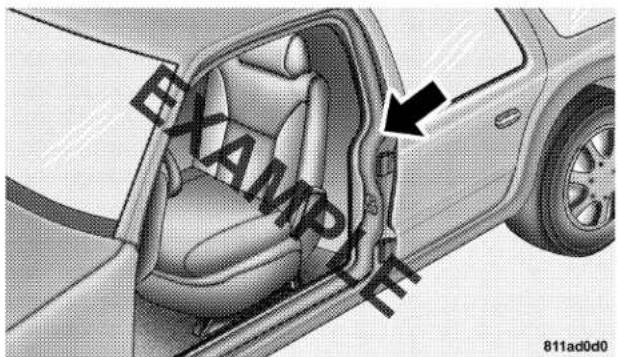
Tire Placard Location
Tire and Loading Information Placard
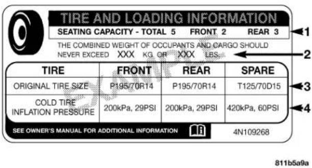
Tire and Loading Information
This placard tells you important information about the,
1) number of people that can be carried in the vehicle
2) the total weight your vehicle can carry
3) the tire size designed for your vehicle
4) the cold tire inflation pressures for the front, rear and spare tires.
Loading
The vehicle maximum load on the tire must not exceed the load carrying capacity of the tire on your vehicle. You will not exceed the tire's load carrying capacity if you adhere to the loading conditions, tire size and cold tire inflation pressures specified on the Tire and Loading Information placard and the Vehicle Loading section of this manual.
NOTE: Under a maximum loaded vehicle condition, gross axle weight ratings (GAWR's) for the front and rear axles must not be exceeded. For further information on GAWR's, vehicle loading and trailer towing, see the Vehicle Loading section of this manual.
208 STARTING AND OPERATING
To determine the maximum loading conditions of your vehicle, locate the statement "The combined weight of occupants and cargo should never exceed XXX kg or XXX lbs." on the Tire and Loading Information placard. The combined weight of occupants, cargo/luggage and trailer tongue weight (if applicable) should never exceed the weight referenced here.
Steps for Determining Correct Load Limit
- Locate the statement "The combined weight of occupants and cargo should never exceed XXX pounds" on your vehicle's placard.
- Determine the combined weight of the driver and passengers that will be riding in your vehicle.
- Subtract the combined weight of the driver and passengers from XXX kilograms or XXX pounds.
- The resulting figure equals the available amount of cargo and luggage load capacity. For example, if "XXX" amount equals 1400 lbs. and there will be five 150 lb.
passengers in your vehicle, the amount of available cargo and luggage load capacity is 650 lb. (since 5 × 150 = 750 , and 1400 - 750 = 650 lb.)
- Determine the combined weight of luggage and cargo being loaded on the vehicle. That weight may not safely exceed the available cargo and luggage load capacity calculated in step 4.
- If your vehicle will be towing a trailer, load from your trailer will be transferred to your vehicle. Consult this manual to determine how this reduces the available cargo and luggage load capacity of your vehicle.
NOTE: The following table shows examples on how to calculate total load, cargo/luggage and towing capacities of your vehicle with varying seating configurations and number and size of occupants. This table is for illustration purposes only and may not be accurate for the seating and load carry capacity of your vehicle.
NOTE: For the following example the combined weight of occupants and cargo should never exceed 865 lbs. (392 Kg).
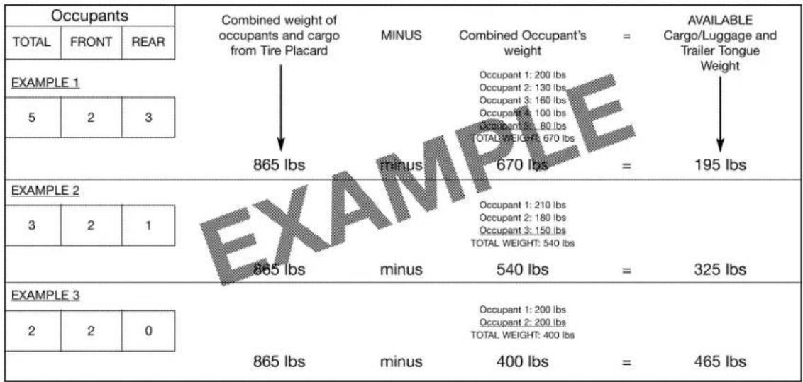
811a4d11
WARNING!
Overloading of your tires is dangerous. Overloading can cause tire failure, affect vehicle handling, and increase your stopping distance. Use tires of the recommended load capacity for your vehicle. Never overload them.
TIRES—GENERAL INFORMATION
Tire Pressure
Proper tire inflation pressure is essential to the safe and satisfactory operation of your vehicle. Three primary areas are affected by improper tire pressure:
1. Safety—
WARNING!
Improperly inflated tires are dangerous and can cause accidents.
- Under inflation increases tire flexing and can result in tire failure.
- Over inflation reduces a tire's ability to cushion shock. Objects on the road and chuck holes can cause damage that results in tire failure.
- Unequal tire pressures can cause steering problems. You could lose control of your vehicle.
• Over inflated or under inflated tires can affect vehicle handling and can fail suddenly, resulting in loss of vehicle control. - Unequal tire pressures from one side of the vehicle to the other can cause the vehicle to drift to the right or left. Always drive with each tire inflated to the recommended cold tire inflation pressure.
2. Economy—
Improper inflation pressures can cause uneven wear patterns to develop across the tire tread. These abnormal wear patterns will reduce tread life resulting in a need for earlier tire replacement. Underinflation also increases tire rolling resistance and results in higher fuel consumption.
3. Ride Comfort and Vehicle Stability—
Proper tire inflation contributes to a comfortable ride. Overinflation produces a jarring and uncomfortable ride.
Tire Inflation Pressures
The proper cold tire inflation pressure for passenger cars is listed on either the face of the driver's door or the driver's side "B" pillar. For vehicles other than passenger cars, the cold tire inflation pressures are listed on either the "B" pillar, the Certification Label or in the Tire Inflation Pressures brochure in the glove compartment.
Some vehicles may have Supplemental Tire Pressure Information for vehicle loads that are less than the maximum loaded vehicle condition. These pressure conditions will be found in the "Supplemental Tire Pressure Information" section of this manual.
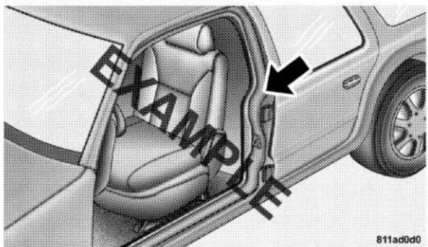
Tire Placard Location
212 STARTING AND OPERATING
The pressure should be checked and adjusted as well as inspecting for signs of tire wear or visible damage at least once a month. Use a good quality pocket-type gauge to check tire pressure. Do not make a visual judgement when determining proper inflation. Radial tires may look properly inflated even when they are underinflated.
CAUTION!
After inspecting or adjusting the tire pressure always reinstall the valve stem cap-if equipped. This will prevent moisture and dirt from entering the valve stem, which could damage the valve stem.
Inflation pressures specified on the placard are always "cold tire inflation pressure". Cold tire inflation pressure is defined as the tire pressure after the vehicle has not been driven for at least 3 hours, or driven less than 1 mile
(1 km) after a 3 hour period. The cold tire inflation pressure must not exceed the maximum inflation pressure molded into the tire side wall.
Check tire pressures more often if subject to a wide range of outdoor temperatures, as tire pressures vary with temperature changes.
Tire pressures change by approximately 1 psi (7 kPa) per 12^ F ( 7^ C) of air temperature change. Keep this in mind when checking tire pressure inside a garage especially in the winter.
Example: If garage temperature = 68^ F ( 20^ C) and the outside temperature = 32^ F ( 0^ C) then the cold tire inflation pressure should be increased by 3 psi (21 kPa), which equals 1 psi (7 kPa) for every 12^ F ( 7^ C) for this outside temperature condition.
Tire pressure may increase from 2 to 6 psi (13 to 40 kPa) during operation. DO NOT reduce this normal pressure build up or your tire pressure will be too low.
Tire Pressures for High Speed Operation
The manufacturer advocates driving at safe speeds within posted speed limits. Where speed limits or conditions are such that the vehicle can be driven at high speeds, maintaining correct tire inflation pressure is very important. Increased tire pressure and reduced vehicle loading may be required for high speed vehicle operation. Refer to original equipment or an authorized tire dealer for recommended safe operating speeds, loading and cold tire inflation pressures.
WARNING!
High speed driving with your vehicle under maximum load is dangerous. The added strain on your tires could cause them to fail. You could have a serious accident. Don't drive a vehicle loaded to the maximum capacity at continuous speeds above 75 mph (120 km/h).
Radial-Ply Tires
WARNING!
Combining radial ply tires with other types of tires on your vehicle will cause your vehicle to handle poorly. The instability could cause an accident. Always use radial ply tires in sets of four (or 6, in case of trucks with dual rear wheels). Never combine them with other types of tires.
Cuts and punctures in radial tires are repairable only in the tread area because of sidewall flexing. Consult your authorized tire dealer for radial tire repairs.
Compact Spare Tire — If Equipped
The compact spare is for temporary emergency use with radial tires. It is engineered to be used on your style vehicle only. Since this tire has limited tread life, the original tire should be repaired (or replaced) and reinstalled at the first opportunity.
WARNING!
Temporary use spare tires are for emergency use only. With these tires, do not drive more than 50 mph (80 km/h). Temporary-use spare tires have limited tread life. When two or more tread wear indicators appear in adjacent grooves, the temporary use spare tire needs to be replaced. Be sure to follow the warnings which apply to your spare. Failure to do so could result in spare tire failure and loss of vehicle control.
Do not install a wheel cover or attempt to mount a conventional tire on the compact spare wheel, since the wheel is designed specifically for the compact spare.
Do not install more than one compact spare tire/wheel on the vehicle at any given time.
CAUTION!
Because of the reduced ground clearance, do not take your vehicle through an automatic car wash with the compact spare installed. Damage to the vehicle may result.
Limited Use Spare — If Equipped
The limited use spare tire is for temporary emergency use on your vehicle. This tire is identified by a limited use spare tire warning label located on the limited use spare tire and wheel assembly. This tire may look like the original equipped tire on the front or rear axle of your vehicle, but it is not. Installation of this limited use spare tire affects vehicle handling. Since it is not the same tire, replace (or repair) the original tire and reinstall on vehicle at the first opportunity.
WARNING!
The limited use spare tires are for emergency use only. Installation of this limited use spare tire affects vehicle handling. With this tire, do not drive more than 60 mph (100 km/h). Keep inflated to the cold tire inflation pressure listed on either your tire placard or limited use spare tire and wheel assembly. Replace (or repair) the original tire at the first opportunity and reinstall it on your vehicle. Failure to do so could result in loss of vehicle control.
Tire Spinning
When stuck in mud, sand, snow, or ice conditions, do not spin your vehicle's wheels above 35 mph (55 km/h).
See the paragraph on Freeing A Stuck Vehicle in Section 6 of this manual.
WARNING!
Fast spinning tires can be dangerous. Forces generated by excessive wheel speeds may cause tire damage or failure. A tire could explode and injure someone. Do not spin your vehicle's wheels faster than 35 mph (55 km/h) when you are stuck. And don't let anyone near a spinning wheel, no matter what the speed.
Tread Wear Indicators
Tread wear indicators are in the original equipment tires to help you in determining when your tires should be replaced.
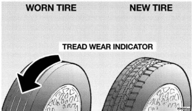
These indicators are molded into the bottom of the tread grooves and will appear as bands when the tread depth becomes 1/16 inch (2 mm). When the indicators appear in 2 or more adjacent grooves, the tire should be replaced.
Many states have laws requiring tire replacement at this point.
Replacement Tires
The tires on your new vehicle provide a balance of many characteristics. They should be inspected regularly for wear and correct cold tire inflation pressure. The manufacturer strongly recommends that you use tires equivalent to the originals in size, quality and performance when replacement is needed (see the paragraph on tread wear indicators). Refer to the Tire and Loading Information placard for the size designation of your tire. The service description and load identification will be found on the original equipment tire. Failure to use equivalent replacement tires may adversely affect the safety, handling, and ride of your vehicle. We recommend that you contact your original equipment or an authorized tire dealer with any questions you may have on tire specifications or capability.
WARNING!
- Do not use a tire, wheel size or rating other than that specified for your vehicle. Some combinations of unapproved tires and wheels may change suspension dimensions and performance characteristics, resulting in changes to steering, handling, and braking of your vehicle. This can cause unpredictable handling and stress to steering and suspension components. You could lose control and have an accident resulting in serious injury or death. Use only the tire and wheel sizes with load ratings approved for your vehicle.
- Never use a tire with a smaller load index or capacity, other than what was originally equipped on your vehicle. Using a tire with a smaller load index could result in tire overloading and failure. You could lose control and have an accident.
- Failure to equip your vehicle with tires having adequate speed capability can result in sudden tire failure and loss of vehicle control.
CAUTION!
Replacing original tires with tires of a different size may result in false speedometer and odometer readings.
Alignment And Balance
Poor suspension alignment may result in:
- Fast tire wear.
- Uneven tire wear, such as feathering and one-sided wear.
• Vehicle pull to right or left.
Tires may also cause the vehicle to pull to the left or right. Alignment will not correct this condition. See your dealer for proper diagnosis.
Improper alignment will not cause vehicle vibration. Vibration may be a result of tire and wheel out-of-balance. Proper balancing will reduce vibration and avoid tire cupping and spotty wear.
TIRE CHAINS
Due to limited clearance, tire chains are not recommended.
CAUTION!
Damage to the vehicle may result if tire chains are used.
SNOW TIRES
Some areas of the country require the use of snow tires during winter. Standard tires are of the all season type and satisfy this requirement as indicated by the M+S designation on the tire side wall.
If you need snow tires, select tires equivalent in size and type to the original equipment tires. Use snow tires only in sets of 4, failure to do so may adversely affect the safety and handling of your vehicle.
Snow tires generally have lower speed ratings than what was originally equipped with your vehicle and should not be operated at sustained speeds over 75 mph (120 km/h).
220 STARTING AND OPERATING
Tire Rotation Recommendations
Tires on the front and rear axles of vehicles operate at different loads and perform different steering, driving and braking functions. For these reasons, they wear at unequal rates, and tend to develop irregular wear patterns.
These effects can be reduced by timely rotation of tires. The benefits of rotation are especially worthwhile with aggressive tread designs such as those on all season type tires. Rotation will increase tread life, help to maintain mud, snow and wet traction levels, and contribute to a smooth, quiet ride.
Follow the recommended tire rotation frequency for your type of driving found in the "Maintenance Schedules" Section of this manual. More frequent rotation is permissible if desired. The reasons for any rapid or unusual
wear should be corrected before rotating. The suggested rotation method is the "forward-cross" shown in the diagram.
TIRE ROTATION PATTERN
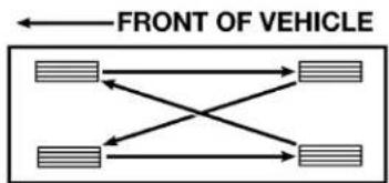
flowchart
graph LR
    A["Top Section"] --> B["Left Side"]
    A --> C["Right Side"]
    D["Bottom Section"] --> E["Left Side"]
    D --> F["Right Side"]
    G["Front of Vehicle"] --> A
    G --> D
    H["Left Side"] --> I["Right Side"]
    H --> J["Bottom Side"]
4 TIRE ROTATION
80ba79fe
FUEL REQUIREMENTS
2.4L Standard Engine and 2.4L Standard Turbo Engine
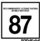
Your vehicle is designed to meet all emission regulations and provide excellent fuel economy when using high quality regular unleaded gasoline with an octane rating of 87. The use of premium gasoline is not recommended. The use of premium gasoline will provide no benefit over high quality regular gasolines, and in some circumstances, may result in poorer performance.
2.4L High Output Turbo Engine
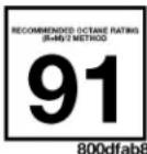
Your engine is designed to meet all emission regulations and provide excellent fuel economy and performance when using
high quality unleaded gasoline having an octane rating of 91. The purchase of higher octane is not required.
The use of high quality unleaded gasoline having an octane rating of 91 is recommended but not required. High quality unleaded gasoline having a minimum octane rating of 87 may safely be used for your vehicle. Use of these lower octane gasolines, however, may result in reduced acceleration performance.
Light spark knock at low engine speeds is not harmful to your engine. However, continued heavy spark knock at high speeds can cause damage and immediate service is required.
Poor quality gasoline can cause problems such as hard starting, stalling and hesitations. If you experience these symptoms, try another brand of gasoline (with the appropriate octane rating for your engine) before considering service for the vehicle.
222 STARTING AND OPERATING
Over 40 automobile manufacturers around the world have issued and endorsed consistent gasoline specifications (the World Wide Fuel Charter, WWFC) to define fuel properties necessary to deliver enhanced emissions, engine performance, and durability for your vehicle. The manufacturer recommends the use of gasolines that meet the WWFC specifications if they are available.
Reformulated Gasoline
Many areas of the country require the use of cleaner burning gasoline referred to as "Reformulated Gasoline".
Reformulated gasolines contain oxygenates, and are specifically blended to reduce vehicle emissions and improve air quality.
The manufacturer supports the use of reformulated gasolines. Properly blended reformulated gasolines will provide excellent performance and durability of engine and fuel system components.
Gasoline/Oxygenate Blends
Some fuel suppliers blend unleaded gasoline with oxygenates such as 10% ethanol, MTBE, and ETBE. Oxygenates are required in some areas of the country during the winter months to reduce carbon monoxide emissions. Fuels blended with these oxygenates may be used in your vehicle.
CAUTION!
DO NOT use gasolines containing Methanol. Use of these blends may result in starting and driveability problems and may damage critical fuel system components.
Problems that result from using methanol/gasoline blends are not the responsibility of the manufacturer. While MTBE is an oxygenate made from Methanol, it does not have the negative effects of Methanol.
MMT In Gasoline
MMT is a manganese containing metallic additive that is blended into some gasoline to increase the octane number. Gasolines blended with MMT offer no performance advantage beyond gasolines of the same octane number without MMT. Gasolines blended with MMT have shown to reduce spark plug life and reduce emission system performance in some vehicles. The manufacturer recommends using gasolines without MMT. Since the MMT content of gasoline may not be indicated on the pump, you should ask your gasoline retailer whether or not his/her gasoline contains MMT.
It is even more important to look for gasolines without MMT in Canada, because MMT can be used at levels higher than those allowed in the United States.
MMT is prohibited in Federal and California reformulated gasolines.
Materials Added to Fuel
All gasoline sold in the United States is required to contain effective detergent additives. Use of additional detergents or other additives is not needed under normal conditions and would result in additional cost. Therefore you should not have to add anything to the fuel.
Fuel System Cautions
| CAUTION! |
| Follow these guidelines to maintain your vehicle's performance: |
- The use of leaded gas is prohibited by Federal law. Using leaded gasoline can impair engine performance, damage the emission control system.
- An out-of-tune engine, or certain fuel or ignition malfunctions, can cause the catalytic converter to overheat. If you notice a pungent burning odor or some light smoke, your engine may be out of tune or malfunctioning and may require immediate service. Contact your dealer for service assistance.
- The use of fuel additives which are now being sold as octane enhancers is not recommended. Most of these products contain high concentrations of methanol. Fuel system damage or vehicle performance problems resulting from the use of such fuels or additives is not the responsibility of the manufacturer.
NOTE: Intentional tampering with emissions control systems can result in civil penalties being assessed against you.
Carbon Monoxide Warnings
WARNING!
Carbon monoxide (CO) in exhaust gases is deadly. Follow the precautions below to prevent carbon monoxide poisoning:
- Do not inhale exhaust gases. They contain carbon monoxide, a colorless and odorless gas which can kill. Never run the engine in a closed area, such as a garage, and never sit in a parked vehicle with the engine running for an extended period. If the vehicle is stopped in an open area with the engine running for more than a short period, adjust the ventilation system to force fresh, outside air into the vehicle.
- Guard against carbon monoxide with proper maintenance. Have the exhaust system inspected every time the vehicle is raised. Have any abnormal conditions repaired promptly. Until repaired, drive with all side windows fully open.
- Keep the liftgate closed when driving your vehicle to prevent carbon monoxide and other poisonous exhaust gases from entering the vehicle.
ADDING FUEL
The fuel tank filler tube has a restricting door about 2 inches (50 mm) inside the opening. If using a portable container, it should have a flexible nozzle long enough to force open the restricting door.
Fuel Filler Cap (Gas Cap)
The gas cap is behind the fuel filler door, on the passenger's side of the vehicle. If the gas cap is lost or damaged, be sure the replacement cap is for use with this vehicle.
NOTE: When removing the fuel filler cap, lay the cap tether in the hook, located on the fuel filler cap door reinforcement.
CAUTION!
Damage to the fuel system or emission control system could result from using an improper fuel tank filler tube cap (gas cap). A poorly fitting cap could let impurities into the fuel system.
226 STARTING AND OPERATING
CAUTION!
A poorly fitting gas cap may cause the Malfunction Indicator Light to turn on.
CAUTION!
To avoid fuel spillage and overfilling, do not "top off" the fuel tank after filling.
NOTE: When the fuel nozzle "clicks" or shuts off, the fuel tank is full.
WARNING!
- Never have any smoking materials lit in or near the vehicle when the gas cap is removed or the tank filled.
- Never add fuel when the engine is running. This is in violation of most state and federal fire regulations and will cause the malfunction indicator light to turn on.
NOTE: Tighten the gas cap about 1/4 turn until you hear one click. This is an indication that cap is properly tightened.
If the gas cap is not tighten properly, the Malfunction Indicator Light will come on. Be sure the gas cap is tightened every time the vehicle is refueled.
WARNING!
A fire may result if gasoline is pumped into a portable container that is inside of a vehicle. You could be burned. Always place gas containers on the ground while filling.
VEHICLE LOADING
Vehicle Loading Capacities
Front Seat Occupants 2
Rear Seat Occupants 2
Luggage....115lbs(52
Rated Vehicle Capacity. 7 1 5 lb (324 kg)
TRAILER TOWING
In this section you will find safety tips and information on limits to the type of towing you can reasonably do with your vehicle. Before towing a trailer carefully review this information to tow your load as efficiently and safely as possible.
Perform maintenance services as prescribed in the maintenance schedules manual. When your vehicle is used for trailer towing, never exceed the gross axle weight rating (GAWR) by the addition of:
• The tongue weight of the trailer.
• The weight of any other type of cargo or equipment put in or on your vehicle.
- Remember that everything put in or on the trailer adds to the load on your vehicle.
228 STARTING AND OPERATING
Warranty
To maintain warranty coverage, follow the requirements and recommendations in this manual concerning vehicles used for trailer towing. However the following conditions must be met:
- The maximum frontal area of the trailer cannot exceed 20 square feet (1.86 square meters).
- The maximum towing capability for your vehicle is 1,000 lbs (454 kg).
- If using a manual transaxle vehicle for trailer towing, all starts must be in FIRST gear to avoid excessive clutch slippage.
- The trailer tongue load must be considered as part of the combined weight of occupants and cargo, and should never exceed the weight referenced on the Tire and Loading Information placard. Refer to the Tire-Safety Information Section in this manual.
- The "D" range can be selected when towing. However, if frequent shifting occurs while in this range, the "3" range must be selected.
NOTE: Using the "3" range while operating the vehicle under heavy operating conditions will improve performance and extend transaxle life by reducing excessive shifting and heat build up.
WARNING!
Connecting trailer brakes to your vehicle's hydraulic brake lines can overload your brake system and cause it to fail. You might not have brakes when you need them and could have an accident.
- Do not attempt to tow a trailer while using a compact spare tire.
- Whenever you pull a trailer, regardless of the trailer size, stop lights and turn signals on the trailer are recommended for motoring safety.
- The automatic transaxle fluid and filter should be changed if you REGULARLY tow a trailer for more than 45 minutes of continuous operation. See Schedule "B" in section 8 of this manual for transaxle fluid change intervals.
NOTE: Check the automatic transaxle fluid level before towing.
NOTE: For vehicles equipped with Autostick. By using the Autostick modes, and selecting a specific gear range, frequent shifting can be avoided. The highest gear range should be selected that allows for adequate performance. For example, choose "4" if the desired speed can be maintained. Choose "3" or "2" if needed to maintain the desired speed.
NOTE: Extended driving at high RPM should be avoided to prevent excess heat generation. A reduction in vehicle speed may be required to avoid extended driving at high RPM. Return to a higher gear range or vehicle speed when road conditions and RPM level allows.
WHAT TO DO IN EMERGENCIES
CONTENTS
■Hazard Warning Flasher....2 3 2
■If Your Engine Overheats....2 3 3
■Jacking And Tire Changing....235
□Jack Location....235
□Spare Tire Stowage 236
□Preparations For Jacking....237
□Jacking Instructions....238
■Jump-Starting Procedures Due To A Low Battery 240
■Driving On Slippery Surfaces....243
□Acceleration....243
□Traction 243
■ Freeing A Stuck Vehicle .....244
■Towing A Disabled Vehicle....245
□With Ignition Key 245
□ Without The Ignition Key .....246
■Convertible Top Manual Override....247
232 WHAT TO DO IN EMERGENCIES
HAZARD WARNING FLASHER
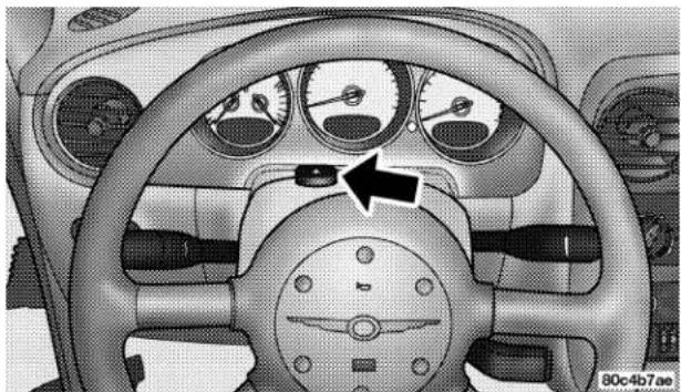
natural_image
Interior view of a car dashboard with steering wheel and gauges (no visible text or symbols)Hazard Flasher Switch
The flasher switch is on top of the steering column, just behind the steering wheel. Depress the switch and both cluster indicators and all front and rear directional signals will flash. Depress the switch again to turn Hazard Warning Flashers off.
Do not use this emergency warning system when the vehicle is in motion. Use it when your vehicle is disabled and is creating a safety hazard for other motorists.
If it is necessary to leave the vehicle to go for service, the flasher system will continue to operate with the ignition key removed and the vehicle locked.
NOTE: With extended use, the flasher may wear down your battery.
IF YOUR ENGINE OVERHEATS
In any of the following situations, you can reduce the potential for overheating by taking the appropriate action.
- On the highways — Slow down.
- In city traffic — While stopped, put transaxle in neutral, but do not increase engine idle speed.
If the pointer rises to the H (red) mark, the instrument cluster will sound a chime. Pull over and stop the vehicle. Idle the vehicle with the air conditioner turned off until the pointer drops back into the normal range. If the pointer remains on the H (red) mark, turn the engine off immediately and call for service.
NOTE: There are steps that you can take to slow down an impending overheat condition. If your air conditioner is on, turn it off. The air conditioning system adds heat to the engine cooling system and turning off the A/C removes this heat. You can also turn the Temperature control to maximum heat, the Mode control to floor, and the fan control to High. This allows the heater core to act as a supplement to the radiator and aids in removing heat from the engine cooling system.
CAUTION!
Driving with a hot cooling system could damage your vehicle. If temperature gauge reads "H", pull over and stop the vehicle. Idle the vehicle with the air conditioner turned off until the pointer drops back into the normal range. After appropriate action has been taken, if the pointer remains on the "H", turn the engine off immediately, and call for service.
WARNING!
A hot engine cooling system is dangerous. You or others could be badly burned by steam or boiling coolant. You may want to call a service center if your vehicle overheats. If you decide to look under the hood yourself, refer to Section 7, Maintenance, of this manual. Follow the warnings under the Cooling System Pressure Cap paragraph.
JACKING AND TIRE CHANGING
WARNING!
- Getting under a jacked-up vehicle is dangerous. The vehicle could slip off the jack and fall on you. You could be crushed. Never get any part of your body under a vehicle that is on a jack. Never start or run the engine while the vehicle is on a jack. If you need to get under a raised vehicle, take it to a service center where it can be raised on a lift.
- The jack is designed to use as a tool for changing tires only. The jack should not be used to lift the vehicle for service purposes. The vehicle should be jacked on a firm level surface only. Avoid ice or slippery areas.
Jack Location
The jack and jack-handle are stowed behind the right rear side trim panel in the cargo area.
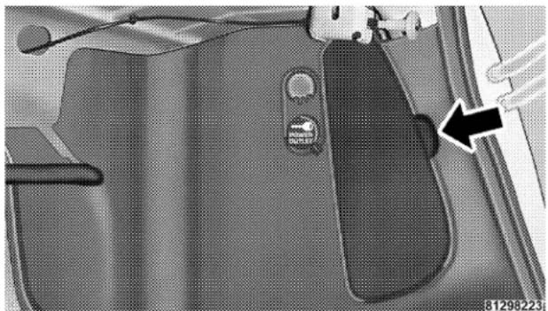
natural_image
Close-up of a car's front panel showing the door, seat, and dashboard (no text or symbols visible)Jack Location
Do not attempt to raise this vehicle using a bumper jack.
236 WHAT TO DO IN EMERGENCIES
Spare Tire Stowage
The compact spare tire is stowed under the rear of the vehicle by means of a hook/basket mechanism. To remove or stow the compact spare, use the jack handle to rotate the "spare tire drive" nut. The nut is located under the rear scuff plate at the right rear of the cargo area, just inside the deck lid opening.
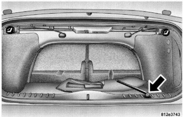
natural_image
Interior view of a car's backrest with visible structural components and a directional arrow (no text or symbols)Lowering Spare Tire
Spare Tire Removal
Lift up the plastic cover on the scuff plate and fit the jack-handle over the drive nut. Rotate the nut to the left until you can remove the swivel hook from the stowage basket. Swing the basket down to remove the compact spare tire.
CAUTION!
The hook is designed for use with the jack handle only. Use of an air wrench or other power tools is not recommended and can damage the winch.
Preparations For Jacking
Park the vehicle on a firm level surface, avoid ice or slippery areas, set the parking brake and place the gear selector in PARK (automatic transaxle) or REVERSE (manual transaxle). Turn OFF the ignition.
WARNING!
Do not attempt to change a tire on the side of the vehicle close to moving traffic. Pull far enough off the road to avoid the danger of being hit when operating the jack or changing the wheel.
- Turn on the Hazard Warning Flasher.
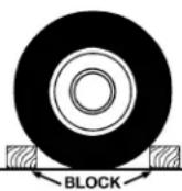
- Block both the front and rear of the wheel diagonally opposite the jacking position. For example, if changing the right front tire, block the left rear wheel.
- Passengers should not remain in the vehicle while the vehicle is being jacked.
238 WHAT TO DO IN EMERGENCIES
Jacking Instructions
- Remove the scissors jack and lug wrench from the stowage bag.
NOTE: If equipped with a center cap that covers the wheel nuts, pry off the cap using the small end of the lug wrench. To reinstall the cap, make sure it is properly lined up before pushing it on to the wheel. - Loosen, but do not remove, the wheel nuts by turning them to the left one turn while the wheel is still on the ground.
CAUTION!
Do not attempt to raise the vehicle by jacking on the crossmember below the radiator, on the front suspension crossmember, or on the rear axle assembly.
- There are two front jacking locations on each side of the body and rear jacking locations located on the trailing arm bracket under the triangular cut out symbol. Turn the jack screw to the right until the jack head is properly engaged with the lift area closest to the wheel to be changed.
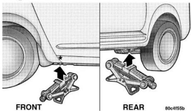
Do not raise the vehicle until you are sure the jack is securely engaged.
- Raise the vehicle by turning the jack screw to the right, using the swivel wrench. Raise the vehicle only until the tire just clears the surface and enough clearance is obtained to install the spare tire. Minimum tire lift provides maximum stability.
WARNING!
Raising the vehicle higher than necessary can make the vehicle less stable. It could slip off the jack and hurt someone near it. Raise the vehicle only enough to remove the tire.
- Remove the wheel nuts and pull the wheel and wheel covers where applicable off the hub. Install the spare wheel and wheel nuts with the cone shaped end of the
nuts toward the wheel. Lightly tighten the nuts. To avoid the risk of forcing the vehicle off the jack, do not tighten the nuts fully until the vehicle has been lowered.
WARNING!
To avoid possible personal injury, handle the wheel covers with care to avoid contact with any sharp edges.
NOTE: The wheel cover is held on the wheel by the wheel nuts. When reinstalling original wheel, properly align the wheel cover to the valve stem, place the wheel cover onto the wheel, then install the wheel nuts.
- Lower the vehicle by turning the jack screw to the left.
- Finish tightening the nuts. Push down on the wrench while tightening the wheel nuts. Alternate nuts until each nut has been tightened twice. Correct wheel nut torque is
240 WHAT TO DO IN EMERGENCIES
100 ft. lbs (135 N·m). If you doubt that you have tightened the nuts correctly, have them checked with a torque wrench by your dealer or at a service station.
- Remove the wheel blocks and lower the jack until it is free. Stow the lug wrench, replaced tire, and jack. Secure all parts using the means provided.
WARNING!
A loose tire or jack thrown forward in a collision or hard stop could endanger the occupants of the vehicle. Always stow the jack parts and the spare tire in the places provided.
- Place the deflated (flat) tire in the cargo area, have the tire repaired or replaced as soon as possible.
WARNING!
A loose tire thrown forward in a collision or hard stop could injure the occupants in the vehicle. Have the deflated (flat) tire repaired or replaced immediately.
- Check the tire pressure as soon as possible. Correct pressure as required.
JUMP-STARTING PROCEDURES DUE TO A LOW BATTERY
WARNING!
Take care to avoid the radiator cooling fan whenever the hood is raised. It can start anytime the ignition switch is on. You can be hurt by the fan.
WARNING!
Do not attempt to push or tow your vehicle to get it started. Vehicles equipped with an automatic transaxle cannot be started this way. Unburned fuel could enter the catalytic converter and once the engine has started, ignite and damage the converter and vehicle. If the vehicle has a discharged battery, booster cables may be used to obtain a start from another vehicle. This type of start can be dangerous if done improperly, so follow this procedure carefully.
-
Wear eye protection and remove any metal jewelry such as watch bands or bracelets that might make an inadvertent electrical contact.
-
When boosting from a battery in another vehicle, park that vehicle within booster cable reach but without letting the vehicles touch. Set parking brake, place automatic transaxle in PARK (manual transaxle in NEU-TRAL) and turn ignition to OFF for both vehicles.
- Turn off the heater, radio and all unnecessary electrical loads.
- Connect one end of a jumper cable to the positive terminal of the booster battery. Connect the other end of the jumper cable to the positive jump start terminal, located near the Power Distribution Center, of the vehicle with the discharged battery.
WARNING!
Battery fluid is a corrosive acid solution; do not allow battery fluid to contact eyes, skin or clothing. Don't lean over battery when attaching clamps or allow the clamps to touch each other. If acid splashes in eyes or on skin, flush the contaminated area immediately with large quantities of water.
A battery generates hydrogen gas which is flammable and explosive. Keep flame or spark away from the vent holes. Do not use a booster battery or any other booster source with an output that exceeds 12 volts.
- Connect the other cable, first to the negative terminal of the booster battery and then to the negative jump start terminal, located near the hood release latch, of the vehicle with the discharged battery. Make sure you have a good contact.
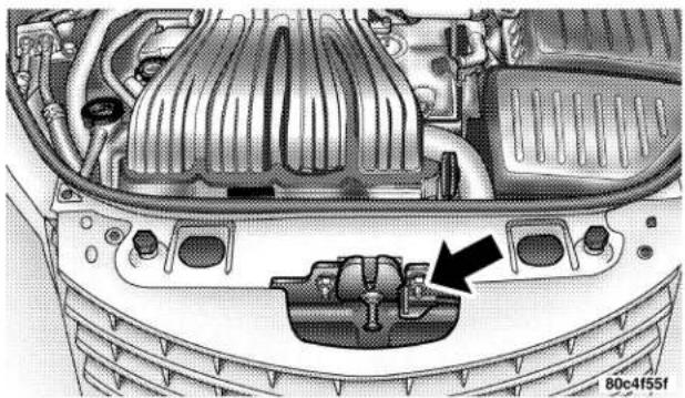
natural_image
Interior view of a car's dashboard and engine compartment showing internal components (no text or symbols)Negative Jump Start
- Turn the ignition switch to the ON position for 3 seconds before moving the ignition switch to the START position.
-
Start the engine in the vehicle that has the booster battery, let the engine idle a few minutes, then start the engine in the vehicle with the discharged battery.
-
When removing the jumper cables, reverse the sequence exactly. Be careful of the moving belts and fan.
DRIVING ON SLIPPERY SURFACES
Acceleration
Rapid acceleration on snow covered, wet, or other slippery surfaces may cause the front wheels to pull erratically to the right or left. This phenomenon occurs when there is a difference in the surface traction under the front (driving) wheels.
WARNING!
Rapid acceleration on slippery surfaces is dangerous. Unequal traction can cause sudden pulling of the front wheels. You could lose control of the vehicle and possibly have an accident. Accelerate slowly and carefully whenever there is likely to be poor traction (ice, snow, wet, mud, loose sand, etc.).
Traction
When driving on wet or slushy roads, it is possible for a wedge of water to build up between the tire and road surface. This is hydroplaning and may cause partial or complete loss of vehicle control and stopping ability. To reduce this possibility, the following precautions should be observed:
- Slow down during rainstorms or when roads are slushy.
244 WHAT TO DO IN EMERGENCIES
- Slow down if road has standing water or puddles.
- Replace tires when tread wear indicators first become visible.
- Keep tires properly inflated.
- Maintain enough distance between your vehicle and the vehicle in front of you to avoid a collision in a sudden stop.
FREEING A STUCK VEHICLE
NOTE: If your vehicle is equipped with Traction Control, turn the system OFF before attempting to "rock" the vehicle.
If your vehicle becomes stuck in mud, sand or snow, it can often be moved by a rocking motion. Turn your steering wheel right and left to clear the area around the front wheels. Then shift back and forth between Reverse and First gear. Usually the least accelerator pedal pressure to maintain the rocking motion without spinning the wheels is most effective.
WARNING!
Fast spinning tires can be dangerous. Forces generated by excessive wheel speeds may cause tire damage or failure. A tire could explode and injure someone. Do not spin your vehicle's wheels faster than 35 mph (55km/h) when you are stuck. And don't let anyone near a spinning wheel, no matter what the speed.
CAUTION!
Racing the engine or spinning the wheels too fast may lead to transaxle overheating and failure. It can also damage the tires. Do not spin the wheels above 35 mph (55km/h).
TOWING A DISABLED VEHICLE
With Ignition Key
Four Speed Automatic Transaxle
Your vehicle may be towed under the following conditions: The steering column must be unlocked and the gear selector must be in NEUTRAL, the distance to be towed must not exceed 100 miles (160 km), and the towing speed must not exceed 44 mph (72 km/h). If the transaxle is not operative, or if the vehicle is to be towed more than 100 miles (160 km), the vehicle must be towed with the front wheels off the ground to avoid damage to the transaxle.
Manual Transaxle
Your vehicle may be towed if the gearshift lever is in NEUTRAL. If the transaxle is not operative, the vehicle must be towed with the front wheels off the ground.
All Transaxles
CAUTION!
If the vehicle being towed requires steering, the ignition switch must be in the OFF position, not in the LOCK or ACCESSORY positions.
Do not attempt to use sling type equipment when towing. When securing vehicle to flat bed truck, do not attach to front or rear suspension components. Damage to your vehicle may result from improper towing.
If it is necessary to use the accessories while being towed (wipers, defrosters, etc.), the key must be in the ON position, not the ACCESSORY position. Make certain the transaxle remains in NEUTRAL.
Without The Ignition Key
Special care must be taken when the vehicle is towed with the ignition in the LOCK position. A dolly should be used under the front wheels if the rear wheels are raised. Proper towing equipment is necessary to prevent damage to the vehicle.
Towing This Vehicle Behind Another Vehicle (Flat Towing With All Four Wheels On The Ground)
If your vehicle is equipped with a manual transaxle, it may be towed at any legal highway speed, for any distance, if the transaxle is in neutral.
If the ignition key is not available, vehicles with automatic transaxles can not be flat towed at any time.
CONVERTIBLE TOP MANUAL OVERRIDE
If your vehicle is experiencing electrical failure (low battery, etc.) and it is necessary to raise the convertible top, perform the following steps:
- Locate the convertible top motor bleeder screw, which is found in the trunk under the convertible top storage area.
- Turn the screw counterclockwise until the screw stops. This will relieve the hydraulic pressure and allow the convertible top to be raised manually.
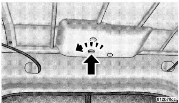
natural_image
Interior view of a car showing a vehicle's rearview and side-mounted air vent with directional arrows (no text or symbols)Bleeder Screw
- Using the latch handle raise the top until the two pins seat themselves in the windshield header.
- Rotate the latch handle clockwise to open the latches.
248 WHAT TO DO IN EMERGENCIES
- Pull down and rotate the handle counterclockwise to engage the latches.
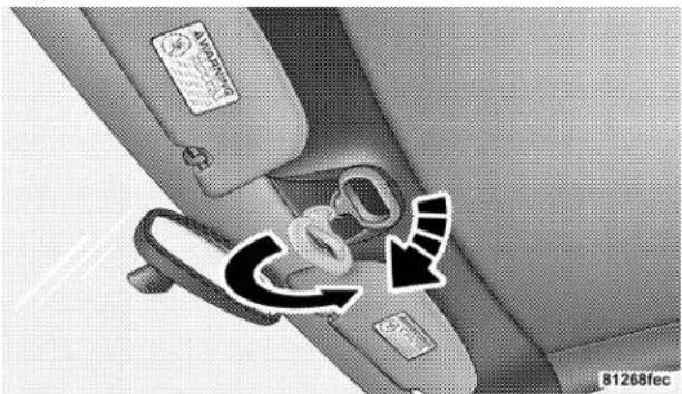
natural_image
Interior view of a car showing a seatbelt and directional arrows (no text or symbols)Engaging Convertible Top
- Raise the handle into the stowed position.
- Close the convertible top motor bleeder screw by turning the screw clockwise until it stops.
MAINTAINING YOUR VEHICLE
CONTENTS
■2.4L Turbo Engine Compartment ..... 2 5 2
■2.4L Engine Compartment....253
■ Onboard Diagnostic System — OBD II .....254
■Emissions Inspection And Maintenance Programs....255
■Replacement Parts....256
■Dealer Service....256
■Maintenance Procedures....257
□Engine Oil....257
□ Drive Belts — Check Condition And Tension . .261
□Spark Plugs 262
□Ignition Wiring System 262
□Catalytic Converter....262
□Engine Timing Belt 264
□Crankcase Emission Control System . . . . . . . 2 6 4
□Fuel Filter 264
□ Air Cleaner Element (Filter) .....264
□ Maintenance-Free Battery .....265
□Air Conditioner Maintenance....267
□ Power Steering — Fluid Check .....268
□Front Suspension Ball Joints....268
□Body Lubrication....269
□Windshield Wiper Blades....269
□Windshield Washer Reservoir....270
□Exhaust System....271
□Cooling System 272
□Hoses And Vacuum/Vapor Harnesses ..... 2 7 7
□Fuel System Connections....277
□Brake System....278
□Automatic Transaxle....280
□Manual Transaxle....284
□Appearance Care And Protection From Corrosion....284
■Convertible Top Care 290
□Washing....290
□General Cleaning....290
□Cloth Top Additional Cleaning Procedure . . . . 2 9 1
□Cloth Top Protection....292
□ Weather Strip Care ....292
■Fuses 292
□ Underhood Fuses (Power Distribution Center) .292
□Interior Fuses....295
■Vehicle Storage....297
■Replacement Bulbs 297
MAINTAINING YOUR VEHICLE 251
■Bulb Replacement....299
□Headlight Bulb Replacement....299
□Front Park/Turn Signal/Side Marker Lights . . 300
□ Front Fog Lights — If Equipped .....300
□Tail/Stop, And Rear Turn Signal Lights ..... 3 0 0
□Back Up Light Bulb 301
□Center High Mounted Stop Light . . . . . . . . . 3 0 1
■Fluids And Capacities....302
■Recommended Fluids, Lubricants And Genuine Parts....303
□Engine 303
□Chassis 304
2.4L TURBO ENGINE COMPARTMENT
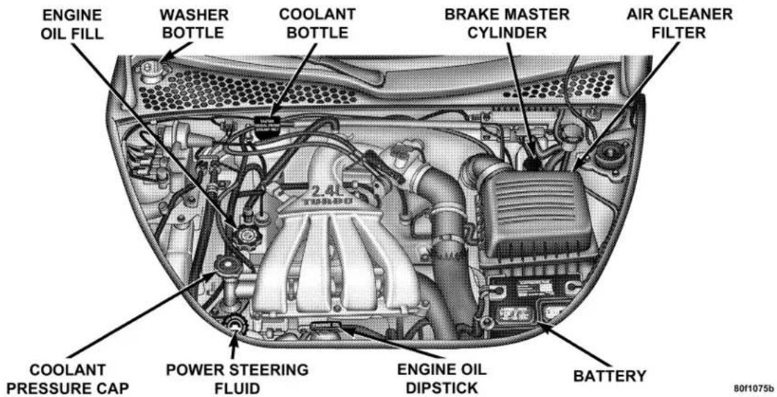
2.4L ENGINE COMPARTMENT
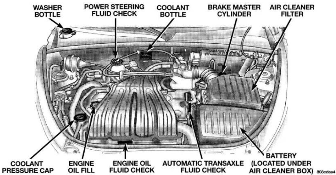
ONBOARD DIAGNOSTIC SYSTEM — OBD II
Your vehicle is equipped with a sophisticated onboard diagnostic system called OBD II. This system monitors the performance of the emissions, engine, and automatic transmission control systems. When these systems are operating properly, your vehicle will provide excellent performance and fuel economy, as well as engine emissions well within current government regulations.
If any of these systems require service, the OBD II system will turn on the "Malfunction Indicator Light." It will also store diagnostic codes and other information to assist your service technician in making repairs. Although your vehicle will usually be drivable and not need towing, see your dealer for service as soon as possible.
CAUTION!
- Prolonged driving with the "Malfunction Indicator Light" on could cause further damage to the emission control system. It could also affect fuel economy and driveability. The vehicle must be serviced before any emissions tests can be performed.
- If the "Malfunction Indicator Light" is flashing while the engine is running, severe catalytic converter damage and power loss will soon occur. Immediate service is required.
EMISSIONS INSPECTION AND MAINTENANCE PROGRAMS
In some localities, it may be a legal requirement to pass an inspection of your vehicle's emissions control system. Failure to pass could prevent vehicle registration.

For states which have an I/M (Inspection and Maintenance) requirement, this check verifies the following: the MIL (Malfunction Indicator Lamp)
is functioning and is not on when the engine is running, and that the OBD (On Board Diagnostic) system is ready for testing.
Normally, the OBD system will be ready. The OBD system may not be ready if your vehicle was recently serviced, if you recently had a dead battery, or a battery replacement. If the OBD system should be determined not ready for the I/M test, your vehicle may fail the test.
Your vehicle has a simple ignition key actuated test which you can use prior to going to the test station. To check if your vehicle's OBD system is ready, you must do the following:
- Insert your ignition key into the ignition switch.
- Turn the ignition to the ON position, but do not crank or start the engine.
- If you crank or start the engine, you will have to start this test over.
- As soon as you turn your key to the ON position, you will see your MIL symbol come on as part of a normal bulb check.
- Approximately 15 seconds later, one of two things will happen:
a. The MIL will flash for about 10 seconds and then return to being fully illuminated until you turn off the ignition key or start the engine. This means that your vehicle's OBD system is not ready and you should not proceed to the I/M station.
b. The MIL will not flash at all and will remain fully illuminated until you turn off the ignition key or start the engine. This means that your vehicle's OBD system is ready and you can proceed to the I/M station.
If your OBD system is not ready, you should see your authorized dealer or repair facility. If your vehicle was recently serviced or had a battery failure or replacement, you may need to do nothing more than drive your vehicle as you normally would in order for your OBD system to update. A recheck with the above test routine may then indicate that the system is now ready.
Regardless of whether your vehicle's OBD system is ready or not ready, if the MIL symbol is illuminated during normal vehicle operation, you should have your vehicle serviced before going to the I/M station. The I/M station can fail your vehicle because the MIL symbol is on with the engine running.
REPLACEMENT PARTS
Use of genuine Mopar® parts for normal/scheduled maintenance and repairs is highly recommended to insure the designed performance. Damage or failures caused by the use of non-Mopar® parts for maintenance and repairs will not be covered by the manufacturer's warranty.
DEALER SERVICE
Your dealer has the qualified service personnel, special tools and equipment to perform all service operations in an expert manner. Service Manuals are available which include detailed service information for your vehicle. Refer to these manuals before attempting any procedure yourself.
NOTE: Intentional tampering with emissions control systems can result in civil penalties being assessed against you.
WARNING!
You can be badly injured working on or around a motor vehicle. Do only that service work for which you have the knowledge and the proper equipment. If you have any doubt about your ability to perform a service job, take your vehicle to a competent mechanic.
MAINTENANCE PROCEDURES
The pages that follow contain the required maintenance services determined by the engineers who designed your vehicle.
Besides the maintenance items for which there are fixed maintenance intervals, there are other items that should operate satisfactorily without periodic maintenance.
However, if a malfunction of these items does occur, it could adversely affect the engine or vehicle performance. These items should be inspected if a malfunction is observed or suspected.
Engine Oil
Checking Oil Level
To assure proper engine lubrication, the engine oil must be maintained at the correct level. Check the oil level at regular intervals, such as every fuel stop.
258 MAINTAINING YOUR VEHICLE
The best time to check the engine oil level is about 5 minutes after a fully warmed engine is shut off or before starting the engine after it has sat overnight.
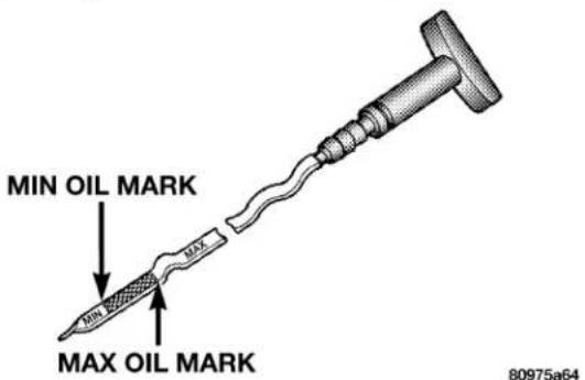
Engine Oil Dipstick
Checking the oil while the vehicle is on level ground, will improve the accuracy of the oil level readings. Maintain the oil level between the MIN and MAX markings on the dipstick. Adding one quart of oil when the reading is at the MIN mark will result in a MAX reading on these engines.
CAUTION!
Overfilling the crankcase as indicated by an oil level above the "Max" mark on the engine oil dipstick will cause oil aeration, which can lead to loss of oil pressure and an increase in oil temperature. This could damage your engine.
Change Engine Oil
Road conditions and your kind of driving affects the interval at which your oil should be changed. Check the following list to decide if any apply to you.
• Day and night temperatures are below 32^ F ( 0^ C).
- Stop and Go driving.
- Extensive engine idling.
- Driving in dusty conditions.
- Short trips of less than 10 miles (16 km).
- More than 50% of your driving is at sustained high speeds during hot weather, above 90°F (32°C).
- Trailer towing.
• Taxi, Police or delivery service (commercial service). - Off-Road or desert operation.
- If equipped for and operating with E-85 (ethanol) fuel.
NOTE: If ANY of these apply to you then change your engine oil every 3,000 miles (5 000 km) or 3 months, whichever comes first, and follow schedule "B—All Engines" of the "Maintenance Schedules" section of this manual.
If none of these apply to you, and your vehicle is equipped with a Non-Turbo Charged Engine then change your engine oil at every interval shown on schedule "A"—NON TURBO in the maintenance schedule section of this manual.
If none of these apply to you, and your vehicle is equipped with a Turbo Charged Engine change your engine oil at every interval shown on schedule "A"—TURBO in the maintenance schedule section of this manual.
NOTE: Under no circumstances should oil change intervals exceed 6000 miles (10 000 km) or 6 months whichever comes first.
Engine Oil Selection
For best performance and maximum protection under all types of operating conditions, the manufacturer only recommends engine oils that are API certified and meet the requirements of DaimlerChrysler Material Standard MS-6395.
American Petroleum Institute (API) Engine Oil Identification Symbol

This symbol means that the oil has been certified by the American Petroleum Institute (API). The manufacturer only recommends API Certified engine oils.
Engine Oil Viscosity (SAE Grade)
SAE 5W-30 engine oil is recommended for all operating temperatures. This engine oil improves low temperature starting and vehicle fuel economy. Refer to your engine oil filler cap for the recommended engine oil viscosity for your vehicle.
For information on engine oil filler cap location, see the Engine Compartment illustration in this section.
Lubricants which do not have both, the engine oil certification mark and the correct SAE viscosity grade number should not be used.
Synthetic Engine Oils
There are a number of engine oils being promoted as either synthetic or semi-synthetic. If you chose to use such a product, use only those oils that are American Petroleum Institute (API) Certified and have the recommended SAE viscosity grade. Follow the maintenance schedule that describes your driving type.
Materials Added To Engine Oils
The manufacture strongly recommends against the addition of any additives (other than leak detection dyes) to the engine oil. Engine oil is an engineered product and it's performance may be impaired by supplemental additives.
Disposing of Used Engine Oil
Care should be taken in disposing of used engine oil from your vehicle. Used oil, indiscriminately discarded, can present a problem to the environment. Contact your dealer, service station, or governmental agency for advice on how and where used oil can be safely discarded in your area.
Engine Oil Filter
The engine oil filter should be replaced at every engine oil change.
Engine Oil Filter Selection
All of this manufacturers engines have a full-flow type disposable oil filter. Use a filter of this type for replacement. The quality of replacement filters varies considerably. Only high quality filters should be used to assure most efficient service. Mopar Engine Oil Filters are high quality oil filters and are recommended.
Drive Belts — Check Condition and Tension
At the mileage shown in the maintenance schedules, check all drive belts for condition and proper tension. Improper belt tension can cause belt slippage and failure.
Inspect the drive belts for evidence of cuts, cracks, or glazing and replace them if there is any sign of damage which could result in belt failure. If adjustment is required, see your authorized dealer for service.
262 MAINTAINING YOUR VEHICLE
Special tools are required to properly measure tension and to restore belt tension to factory specifications. Also, check belt routing to make sure there is no interference between the belts and other engine components.
Spark Plugs
Spark plugs must fire properly to assure engine performance and emission control. New plugs should be installed at the specified mileage. The entire set should be replaced if there is any malfunction due to a faulty spark plug. Refer to the Engine data Label located under the hood for the proper type of spark plug for use in your vehicle.
Ignition Wiring System
The ignition cables should be kept clean and properly connected. Terminals should be fully seated. Cracked, damaged, or faulty cables should be replaced.
Catalytic Converter
The catalytic converter requires the use of unleaded fuel only. Leaded gasoline will destroy the effectiveness of the catalyst as an emission control device.
Under normal operating conditions, the catalytic converter will not require maintenance. However, it is important to keep the engine properly tuned to assure proper catalyst operation and prevent possible catalyst damage.
CAUTION!
Damage to the catalytic converter can result if your vehicle is not kept in proper operating condition. In the event of engine malfunction, particularly involving engine misfire or other apparent loss of performance, have your vehicle serviced promptly. Continued operation of your vehicle with a severe malfunction could cause the converter to overheat, resulting in possible damage to the converter and the vehicle.
WARNING!
A hot exhaust system can start a fire if you park over materials that can burn. Such materials might be grass or leaves coming into contact with your exhaust system. Do not park or operate your vehicle in areas where your exhaust system can contact anything that can burn.
In unusual situations involving grossly malfunctioning engine operation, a scorching odor may suggest severe and abnormal catalyst overheating. If this occurs, stop the vehicle, turn off the engine and allow it to cool. Service, including a tune up to manufacturers specifications, should be obtained immediately.
264 MAINTAINING YOUR VEHICLE
To minimize the possibility of catalyst damage:
- Do not shut off the engine or interrupt the ignition when the transaxle is in gear and the vehicle is in motion.
- Do not try to start the engine by pushing or towing the vehicle.
- Do not idle the engine with any spark plug wires disconnected for prolonged period.
Engine Timing Belt
Replace the engine timing belt at the intervals described in the appropriate maintenance schedule.
Crankcase Emission Control System
Proper operation of this system depends on freedom from sticking or plugging due to deposits. As vehicle mileage builds up, the PCV valve and passages may accumulate deposits. If a valve is not working properly, replace it with a new valve. DO NOT ATTEMPT TO CLEAN THE OLD PCV VALVE!
Check ventilation hose for indication of damage or plugging deposits. Replace if necessary.
Fuel Filter
A plugged fuel filter can cause hard starting or limit the speed at which a vehicle can be driven. Should an excessive amount of dirt accumulate in the fuel tank, frequent filter replacement may be necessary. The fuel filters are located inside the fuel tank. See your dealer for service.
Air Cleaner Element (Filter)
Under normal driving conditions, replace the filter at the intervals shown on Schedule "A". If, however, you drive the vehicle frequently under dusty or severe conditions, the filter element should be inspected periodically and replaced if necessary at the intervals shown on Schedule "B".
NOTE: For vehicles with a Turbo engine, a small amount of oil accumulation in the air cleaner box is normal. The amount will depend on driving style. The air cleaner box should be cleaned out and a new make-up-air filter element should be installed during the normal air filter maintenance procedure.
WARNING!
The air cleaner can provide a measure of protection in the case of engine backfire. Do not remove the air cleaner unless such removal is necessary for repair or maintenance. Make sure that no one is near the engine compartment before starting the vehicle with the air cleaner removed. Failure to do so can result in serious personal injury.
Maintenance-Free Battery
You will never have to add water, nor is periodic maintenance required.
CAUTION!
When servicing the battery, always reinstall the battery thermowrap. The thermowrap provides battery heat protection and will extend overall battery life. Failure to reinstall the thermowrap can result in evaporative loss of the battery fluid.
WARNING!
Battery fluid is a corrosive acid solution and can burn or even blind you. Don't allow battery fluid to contact your eyes, skin or clothing. Don't lean over a battery when attaching clamps. If acid splashes in eyes or on skin, flush the area immediately with large amounts of water.
Battery gas is flammable and explosive. Keep flame or sparks away from the battery. Don't use a booster battery or any other booster source with an output greater than 12 volts. Don't allow cable clamps to touch each other.
Battery posts, terminals and related accessories contain lead and lead compounds. Wash hands after handling.
CAUTION!
It is essential when replacing the cables on the battery that the positive cable is attached to the positive post and the negative cable is attached to the negative post. Battery posts are marked positive (+) and negative (-) and identified on the battery case. Cable clamps should be tight on the terminal posts and free of corrosion. Apply grease to posts and clamps after tightening.
If a "fast charger" is used while the battery is in the vehicle, disconnect both vehicle battery cables before connecting the charger to battery. Do not use a "fast charger" to provide starting voltage as battery damage can result.
Air Conditioner Maintenance
For best possible performance, your air conditioner should be checked and serviced by an Authorized Dealer at the start of each warm season. This service should include cleaning of the condenser fins and a performance test. Drive belt tension should also be checked at this time.
WARNING!
- Use only refrigerants and compressor lubricants approved by the manufacturer for your air conditioning system. Some unapproved refrigerants are flammable and can explode, injuring you. Other unapproved refrigerants or lubricants can cause the system to fail, requiring costly repairs. Refer to Section 3 of the Warranty Information book for further warranty information.
- The air conditioning system contains refrigerant under high pressure. To avoid risk of personal injury or damage to the system, adding refrigerant or any repair requiring lines to be disconnected should be done by an experienced repairman.
Refrigerant Recovery and Recycling
R-134a Air Conditioning Refrigerant is a hydrofluorocarbon (HFC) that is endorsed by the Environmental Protection Agency and is an ozone-saving product. However, the manufacturer recommends that air conditioning service be performed by dealers or other service facilities using recovery and recycling equipment.
NOTE: Use only manufacturer approved A/C System Sealers, Stop Leak Products, Seal Conditioners, Compressor Oil, or Refrigerants.
Power Steering — Fluid Check
Checking the power steering fluid level at a defined service interval is not required. The fluid should only be checked if a leak is suspected, abnormal noises are apparent, and/or the system is not functioning as anticipated. Coordinate inspection efforts through a certified DaimlerChrysler Dealership."
WARNING!
Fluid level should be checked on a level surface and with the engine off to prevent injury from moving parts and to insure accurate fluid level reading. Do not overfill. Use only manufacturers recommended power steering fluid.
If necessary, add fluid to restore to the proper indicated level. With a clean cloth, wipe any spilled fluid from all surfaces. Refer to Recommended Fluids, Lubricants, and Genuine Parts for correct fluid types.
Front Suspension Ball Joints
There are two front suspension lower ball joints that are permanently lubricated. Inspect these ball joints whenever under vehicle service is done. Damaged seals and their corresponding potentially damaged ball joints must be replaced.
Body Lubrication
Locks and all body pivot points, including such items as seat tracks, doors, deck lid and hood hinges, should be lubricated periodically to assure quiet, easy operation and to protect against rust and wear. Prior to the application of any lubricant, the parts concerned should be wiped clean to remove dust and grit; after lubricating excess oil and grease should be removed. Particular attention should also be given to hood latching components to insure proper function. When performing other underhood services, the hood latch, release mechanism and safety catch should be cleaned and lubricated.
The external lock cylinders should be lubricated twice a year, preferably in the fall and spring. Apply a small amount of a high quality lubricant such as Mopar®Lock Cylinder Lubricant directly into the lock cylinder.
Windshield Wiper Blades
Clean the rubber edges of the wiper blades and the windshield periodically with a sponge or soft cloth and a mild non abrasive cleaner or use the washer solvent. This will remove accumulations of salt, waxes or road film and help reduce streaking and smearing.
Operation of the wipers on dry glass for long periods may cause deterioration of the wiper blades. Always use washer fluid when using the wipers to remove salt or dirt from a dry windshield. Avoid using the wiper blades to remove frost or ice from the windshield. make sure that they are not frozen to the glass before turning them on to avoid damaging the blade. Keep the blade rubber out of contact with petroleum products such as engine oil, gasoline, etc.
Windshield Wiper Blade Replacement
- Lift the wiper arm away from the glass.
270 MAINTAINING YOUR VEHICLE
- Push the release tab shown in the illustration and slide the wiper blade assembly down along the arm. Gently place the wiper arm on the windshield.
- Install the new blade assembly onto the wiper arm tip until it locks in place.
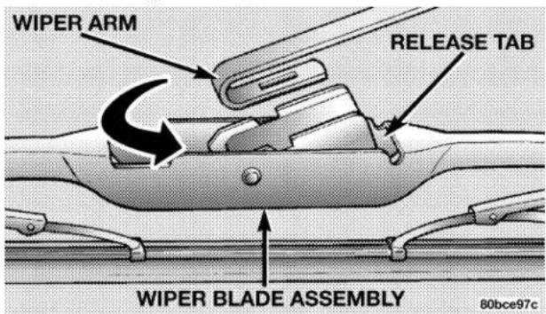
Windshield Washer Reservoir
The washer fluid reservoir is located in the rear of the engine compartment on the passenger side and should be checked for fluid level at regular intervals. Fill the reservoir with windshield washer solvent (not radiator antifreeze).
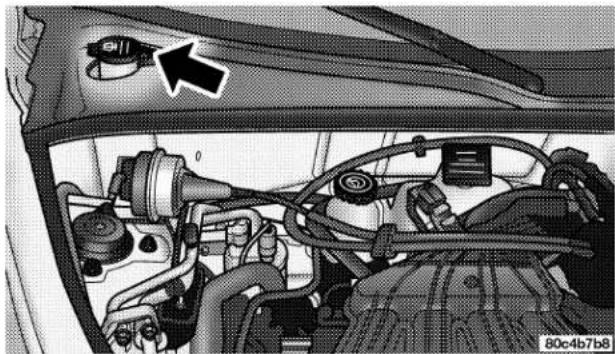
natural_image
Interior view of a car showing engine compartment with hoses and a highlighted valve (no text or symbols visible)Washer Fluid Reservoir
Exhaust System
The best protection against carbon monoxide entry into the vehicle body is a properly maintained engine exhaust system.
If you notice a change in the sound of the exhaust system, or if exhaust fumes can be detected inside the vehicle, or when the underside or rear of the vehicle is damaged; have a competent technician inspect the complete exhaust system and adjacent body areas for broken, damaged, deteriorated, or mispositioned parts. Open seams or loose connections could permit exhaust fumes to seep into the passenger compartment. In addition, inspect the exhaust system each time the vehicle is raised for an oil change or lubrication. Replace as required.
WARNING!
Exhaust gases can injure or kill. They contain carbon monoxide which is colorless and odorless. Breathing it can make you unconscious and can eventually poison you. Follow the above precautions to keep your exhaust system as safe as possible.
Cooling System
WARNING!
- When working near the radiator cooling fan, disconnect the fan motor lead or turn the ignition switch to the OFF position. The fan is temperature controlled and can start at any time the ignition switch is in the ON position.
- You or others can be badly burned by hot coolant or steam from your radiator. If you see or hear steam coming from under the hood, don't open the hood until the radiator has had time to cool. Never try to open a cooling system pressure cap when the radiator is hot.
Coolant Checks
Check engine coolant (antifreeze) protection every 12 months (before the onset of freezing weather, where applicable). If coolant is dirty or rusty in appearance, the system should be drained, flushed and refilled with fresh coolant.
Check the front of the radiator for an accumulation of bugs, leaves, etc. Clean the radiator by gently spraying water from a garden hose at the back of the core.
Check the coolant recovery bottle tubing for brittle rubber, cracking, tears, cuts and tightness of the connection at the bottle and radiator. Inspect the entire system for leaks.
With the engine at normal operating temperature (but not running), check the cooling system pressure cap for proper vacuum sealing by draining a small amount of coolant from the radiator drain cock. If the cap is sealing properly, the engine coolant (antifreeze) will begin to drain from the coolant recovery bottle. DO NOT REMOVE THE COOLANT PRESSURE CAP WHEN THE COOLING SYSTEM IS HOT.
Cooling System — Drain, Flush and Refill
At the intervals shown on the Maintenance Schedules, the system should be drained, flushed and refilled.
If the solution is dirty and contains a considerable amount of sediment, clean and flush with a reliable cooling system cleaner. Follow with a thorough rinsing to remove all deposits and chemicals. Discard oil antifreeze solution.
Selection Of Coolant
Use only the manufacturers recommended coolant, refer to Recommended Fluids, Lubricants and Genuine Parts for correct coolant type.
CAUTION!
Mixing of coolants other than specified engine coolants, may result in engine damage that may not be covered under the new vehicle warranty, and decreased corrosion protection. If a non-HOAT coolant is introduced into the cooling system in an emergency, it should be replaced with the specified coolant as soon as possible.
Do not use plain water alone or alcohol base engine coolant (antifreeze) products. Do not use additional rust inhibitors or antirust products, as they may not be compatible with the radiator engine coolant and may plug the radiator.
This vehicle has not been designed for use with Propylene Glycol based coolants. Use of Propylene Glycol based coolants is not recommended.
Adding Coolant
When adding coolant, or refilling the system, a minimum solution of 50% recommended HOAT ethylene glycol engine coolant (antifreeze) and distilled water should be used. Use higher concentrations (not to exceed 70%) if temperatures below -37^ ( -34^ ) are anticipated.
Use only high purity water such as distilled or deionized water when mixing the water/engine coolant solution. The use of lower quality water will reduce the amount of corrosion protection in the engine cooling system.
Please note that it is the owner's responsibility to maintain the proper level of protection against freezing according to the temperatures occurring in the area where the vehicle is operated.
NOTE: Mixing coolant types will decrease the life of the engine coolant and will require more frequent coolant changes.
Cooling System Pressure Cap
The cap must be fully tightened to prevent loss of coolant, and to insure that coolant will return to the radiator from the coolant recovery bottle.
The cap should be inspected and cleaned if there is any accumulation of foreign material on the sealing surfaces.
WARNING!
The warning words "DO NOT OPEN HOT" on the cooling system pressure cap are a safety precaution. Never add coolant when the engine is overheated. Do not loosen or remove the cap to cool an overheated engine. Heat causes pressure to build up in the cooling system. To prevent scalding or injury, do not remove the pressure cap while the system is hot or under pressure.
Engine Coolant Disposal
Used ethylene glycol based engine coolant is a regulated substance requiring proper disposal. Check with your local authorities to determine the disposal rules for your community. To prevent ingestion by animals or children do not store ethylene glycol based engine coolant in open containers or allow it to remain in puddles on the ground. If ingested by a child, contact a physician immediately. Clean up any ground spills immediately.
Coolant Level
The coolant recovery bottle provides a quick visual method for determining that the coolant level is adequate. With the engine idling, and warm to normal operating temperature, the level of the coolant in the bottle should be between the "FULL" and "ADD" marks.
The radiator normally remains completely full, so there is no need to remove the radiator cap unless checking for coolant freeze point or replacing coolant. Advise your
276 MAINTAINING YOUR VEHICLE
service attendant of this. As long as the engine operating temperature is satisfactory, the coolant recovery bottle need only be checked once a month.
When additional coolant is needed to maintain the proper level, it should be added to the coolant recovery bottle. Do not overfill.
Points To Remember
NOTE: When the vehicle is stopped after a few kilometers (a few miles) of operation, you may observe vapor coming from the front of the engine compartment. This is normally a result of moisture from rain, snow, or high humidity accumulation on the radiator and being vaporized when the thermostat opens, allowing hot water to enter the radiator.
If an examination of your engine compartment shows no evidence of radiator or hose leaks, the vehicle may be safely driven. The vapor will soon dissipate.
- Do not overfill the coolant recovery bottle.
- Check coolant freeze point in the system.
- If frequent coolant additions are required, the cooling system should be pressure tested for leaks.
- Maintain coolant concentration at 50% HOAT ethylene glycol engine coolant (minimum) and distilled water for proper corrosion protection of your engine which contains aluminum components.
- Make sure that the radiator and coolant recovery bottle hoses are not kinked or obstructed.
- Keep the front of the radiator clean. If your vehicle has air conditioning, keep the front of the condenser clean, also.
- Do not change the thermostat for summer or winter operation. If replacement is ever necessary, install ONLY the correct type thermostat. Other designs may result in unsatisfactory coolant performance, poor gas mileage, and increased emissions.
Hoses And Vacuum/Vapor Harnesses
Inspect surfaces of hoses and nylon tubing for evidence of heat and mechanical damage. Hard or soft spots, brittle rubber, cracking, tears, cuts, abrasions, and excessive swelling indicate deterioration of the rubber.
Pay particular attention to the hoses nearest to high heat sources such as the exhaust manifold. Inspect hose routing to be sure hoses do not touch any heat source or moving component that may cause heat damage or mechanical wear.
Insure nylon tubing in these areas has not melted or collapsed.
Inspect all hose connections such as clamps and couplings to make sure the are secure and no leaks are present.
Components should be replaced immediately if there is any evidence of degradation that could cause failure.
Fuel System Connections
Electronic Fuel Injection high pressure fuel systems are designed with tubes and special connects, connections and clamps which have unique material characteristics to provide adequate sealing and resist attack by deteriorated gasoline.
You are urged to use only the manufactures-specified tubes, connections and clamps, or their equivalent in material and specification, in any fuel system servicing.
278 MAINTAINING YOUR VEHICLE
Brake System
In order to assure brake system performance, all brake system components should be inspected periodically. Suggested service intervals can be found in the Maintenance Section.
WARNING!
Riding the brakes can lead to brake failure and possibly an accident. Driving with your foot resting or riding on the brake pedal can result in abnormally high brake temperatures, excessive lining wear, and possible brake damage. You wouldn't have your full braking capacity in an emergency.
Brake And Power Steering System Hoses
When servicing the vehicle for scheduled maintenance, inspect the surface of the hoses and nylon tubing for evidence of heat and mechanical damage. Hard and brittle rubber, cracking, tears, cuts, abrasions, and excessive swelling suggest deterioration of the rubber. Particular attention should be made to examining those hose surfaces nearest to high heat sources, such as the exhaust manifold.
Inspect all hose clamps and couplings to make sure they are secure and no leaks are present.
Insure nylon tubing in these areas has not melted or collapsed.
NOTE: Often, fluids such as oil, power steering fluid, and brake fluid are used during assembly plant operations to ease the assembly of hoses to couplings. Therefore, oil wetness at the hose-coupling area is not necessarily an indication of leakage. Actual dripping of hot fluid when systems are under pressure (during vehicle operation) should be noted before a hose is replaced based on leakage.
NOTE: Inspection of brake hoses should be done whenever the brake system is serviced and at every engine oil change.
WARNING!
Worn brake hoses can burst and cause brake failure. You could have an accident. If you see any signs of cracking, scuffing, or worn spots, have the brake hoses replaced immediately.
Brake Master Cylinder
The fluid level in the master cylinder should be checked when performing under hood services, or immediately if the brake system warning lamp is on.
Be sure to clean the top of the master cylinder area before removing the cap. If necessary, add fluid to bring the fluid level up to the requirements described on the brake
fluid reservoir. Fluid level can be expected to fall as the brake pads wear. Brake fluid level should be checked when pads are replaced. However, low fluid level may be caused by a leak and a checkup may be needed.
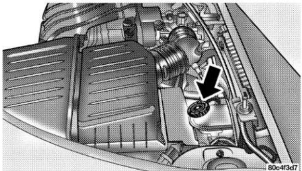
natural_image
Technical diagram of an internal combustion engine showing valve, exhaust pipe, and housing (no text or labels)Brake Fluid Master Cyclinder
280 MAINTAINING YOUR VEHICLE
Use only manufacturers recommended brake fluid, refer to Recommended Fluids, Lubricants and Genuine Parts for correct fluid type.
WARNING!
Use of a brake fluid that may have a lower initial boiling point or unidentified as to specification, may result in sudden brake failure during hard prolonged braking. You could have an accident.
WARNING!
Overfilling the brake fluid reservoir can result in spilling brake fluid on hot engine parts and the brake fluid catching fire.
Use only brake fluid that has been in a tightly closed container to avoid contamination from foreign matter.
Do not allow petroleum based fluid to contaminate the brake fluid as seal damage will result!
Automatic Transaxle
All front wheel drive vehicles have a transmission and differential assembly contained within a single housing.
Selection Of Lubricant
It is important that the proper lubricant is used in the transaxle to assure optimum transaxle performance. Use only manufacturers recommended transmission fluid, refer to Recommended Fluids, Lubricants and Genuine Parts for correct fluid type. It is important that the transmission fluid be maintained at the prescribed level using the recommended fluid.
CAUTION!
Using a transmission fluid other than the manufacturers recommended fluid may cause deterioration in transmission shift quality and/or torque converter shudder. Using a transmission fluid other than the manufacturers recommended fluid will result in more frequent fluid and filter changes. Refer to Recommended Fluids, Lubricants and Genuine Parts for correct fluid type.
Fluid Level Check
The fluid level in the automatic transaxle should be checked whenever the vehicle is serviced. Operation with an improper fluid level will greatly reduce the life of the transaxle and of the fluid.
Procedure For Checking Fluid Level
To properly check the automatic transaxle fluid level, the following procedure must be used:
- The vehicle must be on level ground.
- The engine should be running at curb idle speed for a minimum of 60 seconds.
- Fully apply parking brake.
- Place the gear selector momentarily in each gear position ending with the lever in P (PARK).
282 MAINTAINING YOUR VEHICLE
- Remove the dipstick and determine if the fluid is hot or warm. Hot fluid is approximately 180^ F ( 82^ C), which is the normal operating temperature after the vehicle has been driven at least 15 miles (24 km). The fluid cannot be comfortable held between the finger tips. Warm is when the fluid is between 85^ to 125^ F ( 29^ to 52^ C).
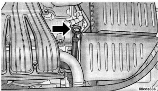
natural_image
Mechanical assembly diagram showing internal components with no visible text or symbolsTransaxle Dipstick Location
- Wipe the dipstick clean and reinsert until seated. Remove dipstick and note reading.
If the fluid is hot, reading should be in the cross hatched area marked "HOT" between the upper two holes in the dipstick.
If the fluid is cold, the fluid level should be between the lower two holes, into the area marked "LOW".
If the fluid level shows low, add sufficient transmission fluid to bring to the proper level.
CAUTION!
Do not overfill. Dirt and water in the transaxle can cause serious damage. To prevent dirt and water from entering the transaxle after checking or replenishing fluid, make certain that the dipstick cap is seated properly.
Fluid And Filter Changes
Automatic transmission fluid and filter should be changed as follows:
Maintenance schedule "A"—Turbo Charged Engines - No change necessary.
Maintenance schedule "B" – Every 60,000 miles (96 000 km) change fluid and filter under the following conditions:
- Police, taxi, limousine, commercial type operation, or trailer towing where the vehicle is driven regularly for more than 45 minutes of continuous operation.
NOTE: Refer to Section 8 of this manual for maintenance schedules.
If the transaxle is disassembled for any reason, the fluid and filter should be changed.
Special Additives
The manufacturer recommends against the addition of any fluid additives to the transaxle. The only exception to this policy is the use of special dyes to aid in detecting fluid leaks. The use of transmission sealers should be avoided as they may adversely affect seals.
284 MAINTAINING YOUR VEHICLE
Manual Transaxle
Lubricant Selection
Use only manufacturers recommended transmission fluid, refer to Recommended Fluids, Lubricants and Genuine Parts for correct fluid type.
Fluid Level Check
Check the fluid level by removing the fill plug. The fluid level should be between the bottom of the fill hole and a point not more that 3/16" (4.7 mm) below the bottom of the hole.
Add fluid, if necessary, to maintain the proper level.
Frequency Of Fluid Change
Under normal operating conditions, the fluid installed at the factory will give satisfactory lubrication for the life of the vehicle. Fluid changes are not necessary unless the following conditions exist:
- The lubricant has become contaminated with water. If contaminated with water, the fluid should be changed immediately.
- If severe usage has occurred, refer to Maintenance Schedule "B" in Section 8 of this manual.
Appearance Care And Protection From Corrosion
Protection Of Body And Paint from Corrosion
Vehicle body care requirements vary according to geographic locations and usage. Chemicals that make roads passable in snow and ice, and those that are sprayed on trees and road surfaces during other seasons, are highly corrosive to the metal in your vehicle. Outside parking, which exposes your vehicle to airborne contaminants, road surfaces on which the vehicle is operated, extreme hot or cold weather and other extreme conditions will have an adverse effect on paint, metal trim, and under-body protection.
The following maintenance recommendations will enable you to obtain maximum benefit from the corrosion resistance built into your vehicle.
What Causes Corrosion?
Corrosion is the result of deterioration or removal of paint and protective coatings from your vehicle.
The most common causes are:
- Road salt, dirt and moisture accumulation.
- Stone and gravel impact.
- Insects, tree sap and tar.
- Salt in the air near sea coast localities.
• Atmospheric fallout/industrial pollutants.
Washing
- Wash your vehicle regularly. Always wash your vehicle in the shade using a mild car wash soap, and rinse the panels completely with clear water.
- If insects, tar or other similar deposits have accumulated on your vehicle, wash it as soon as possible.
- Use Mopar auto polish to remove road film and stains and to polish your vehicle. Take care never to scratch the paint.
- Avoid using abrasive compounds and power buffing that may diminish the gloss or thin out the paint finish.
CAUTION!
Do not use abrasive or strong cleaning materials such as steel wool or scouring powder, which will scratch metal and painted surfaces.
Special Care
- If you drive on salted or dusty roads or if you drive near the ocean, hose off the undercarriage at least once a month.
- It is important that the drain holes in the lower edges of the doors, rocker panels and rear deck lid be kept clear and open.
-
If you detect any stone chips or scratches in the paint, touch them up immediately. The cost of such repairs is considered the responsibility of the owner.
-
Use Mopar touch up paint on scratches or chips as soon as possible. Your dealer has touch up paint to match the color of your vehicle.
- If your vehicle is damaged due to an accident or similar cause which destroys the paint and protective coating have your vehicle repaired as soon as possible. The cost of such repairs is considered the responsibility of the owner.
- If you carry special cargo such as chemicals, fertilizers, deicer salt, etc., be sure that such materials are well packaged and sealed.
- If a lot of driving is done on gravel roads, consider mud or stone shields behind each wheel.
CAUTION!
If your vehicle is equipped with flame or woodgrain graphics, it is recommended that special care be taken when using hand-held pressure washers to clean your vehicle. The pressure of these hand-held car wash wands can vary greatly and could possibly cause damage to the surface of the graphic. Hold the tip of the wand at least 12 inches away from the graphic surface when cleaning the vehicle.
Wheel And Wheel Trim Care
All wheels and wheel trim, especially Aluminum and Chrome plated, should be cleaned regularly, when cool, using mild soap and water to maintain their luster and to prevent corrosion. Wash them with the same soap solution as the body of your vehicle. Rinse wheels thoroughly.
When cleaning extremely dirty wheels, care must be taken in the selection of tire and wheel cleaning chemicals and equipment to prevent damage to the wheels. Only Mopar Wheel Cleaners are recommended. DO NOT USE any of the items listed below which can damage your wheels and wheel trim.
DO NOT USE:
- Any abrasive cleaner
- Any abrasive cleaning pad (such as steel wool) or abrasive brush
- Any cleaner that contains an acid which can react with and discolor the chrome surface.
- Chrome polish
- Oven cleaner
- A car wash that uses carbide-tipped wheel cleaning brushes or acidic solutions.
CAUTION!
Many wheel cleaners contain acids that may harm the wheel surface.
NOTE: Replacement costs for components damaged as a result of not following the recommended cleaning practices are considered the responsibility of the customer.
Interior Care
Use Mopar Fabric Cleaner to clean fabric upholstery and carpeting.
Use Mopar Vinyl Cleaner to clean vinyl upholstery and vinyl trim.
Mopar Total Clean is specifically recommended for leather upholstery.
Your leather upholstery can be best preserved by regular cleaning with a damp soft cloth. Small particles of dirt can act as an abrasive and damage the leather upholstery and should be removed promptly with a damp cloth. Stubborn soils can be removed easily with a soft cloth and Mopar Total Clean. Care should be taken to avoid soaking your leather upholstery with any liquid. Please do not use polishes, oils, cleaning fluids, solvents, detergents, or ammonia based cleaners to clean your leather upholstery. Application of a leather conditioner is not required to maintain the original condition.
WARNING!
Do not use volatile solvents for cleaning purposes. Many are potentially flammable, and if used in closed areas they may cause respiratory harm.
Cleaning Headlights
Your vehicle has plastic headlights that are lighter and less susceptible to stone breakage than glass headlights.
Plastic is not as scratch resistant as glass and therefore different lens cleaning procedures must be followed.
To minimize the possibility of scratching the lenses and reducing light output, avoid wiping with a dry cloth. To remove road dirt, wash with a mild soap solution followed by rinsing.
Do not use abrasive cleaning components, solvents, steel wool or other aggressive material to clean the lenses.
Glass Surfaces
All glass surfaces should be cleaned on a regular basis with any commercial household-type glass cleaner. Never use an abrasive type cleaner. Use caution when
cleaning inside rear windows equipped with electric defrosters. Do not use scrapers or other sharp instruments which may scratch the elements.
Instrument Panel Cover
The instrument panel cover has a low glare surface which minimizes reflections in the windshield. Do not use protectants or other products which may cause undesirable reflections. Use soap and warm water to restore the low glare surface.
Cleaning Plastic Instrument Cluster Lenses
The lenses in front of the instruments in the vehicle are molded in clear plastic. When cleaning the lenses, care must be taken to avoid scratching the plastic.
- Clean with a wet soft rag. A mild soap solution may be used, but do not use high alcohol content of abrasive cleaners. If soap is used, wipe clean with a clean damp rag.
290 MAINTAINING YOUR VEHICLE
2. Dry with a soft tissue.
Seat Belt Maintenance
Do not bleach, dye or clean the belts with chemical solvents or abrasive cleaners. This will weaken the fabric. Sun damage will also weaken the fabric.
If the belts need cleaning, use a mild soap solution or lukewarm water. Do not remove the belts from the vehicle to wash them.
Replace the belts if they appear frayed or worn or if the buckles do not work properly.
CONVERTIBLE TOP CARE
Immediate removal of any contaminant is recommended. Regular washing of the top will enhance its life and appearance, and make successive cleanings easier. Do not subject the top to excessive heat. Frequently vacuum the top and storage compartment.
Washing
Hand washing is highly recommended. Automatic car washing equipment can damage the top material. If you must use an automatic car wash, soft cloth systems are preferred.
CAUTION!
Avoid high pressure car washes, as they can damage the top material. Also, increased water pressure may force water past the weather strips.
General Cleaning
Careful vacuuming of the top before washing is helpful in removing dust and other foreign particles. Wash in partial shade instead of direct sun. Wet the entire vehicle before washing the top. The top should be washed with
a soft, natural bristle scrub brush, and a mild soap solution such as liquid dish washing soap. Do not use detergent.
CAUTION!
Never use an abrasive type cleaner or bleaches. Cleaners should not contain silicones, organic solvents, petroleum distillates or plasticizers. always wait until the top is thoroughly dry before lowering it into the storage area.
Scrub in all directions, covering an area of about two square feet at a time. Avoid heavy scrubbing. Rinse the entire vehicle with water to remove all soap and dirt from the top fabric and to prevent streaking on painted and chrome surfaces. Allow the top to dry before lowering. Vacuuming the top with a wet/dry shop vacuum will decrease the top's drying time, ensure removal of all dirt,
and delete streaks in the material. Multiple cleanings may be necessary to remove stubborn stains. If stains persist, contact your local dealership for further suggestions.
Cloth Top Additional Cleaning Procedure
For additional cleaning assistance in removing stubborn stains, apply Mopar Convertible Cloth Top Cleaner #4883061 to the complete stain, extending 2 inches (50 mm) beyond the stain. With a soft bristle brush, scrub in all directions over the stain. Avoid heavy scrubbing. Rinse the area with warm water. If the stain is still apparent, repeat the cleaning procedure. When the stain is no longer showing, rinse the complete top with warm water. Let the top dry before lowering it.
292 MAINTAINING YOUR VEHICLE
Cloth Top Protection
For appearance purposes, you may wish to protect your Twillfast™ (cloth) top periodically. A fabric protectant such as Scotchguard® is suggested. The top should be clean and dry before application of the protectant.
CAUTION!
Avoid getting Scotchguard® on the surrounding weather strips, moldings, paint, or glass. Damage to these items might occur.
Weather Strip Care
Lubricate all top and door glass weather strips periodically with Mopar Weather Strip Lubricant (part number 4773427), to keep them soft and pliable.
FUSES
Underhood Fuses (Power Distribution Center)
A Power Distribution Center is located in the engine compartment; next to the air cleaner filter. A label identifying the components and circuits is located on the underside of the cover.
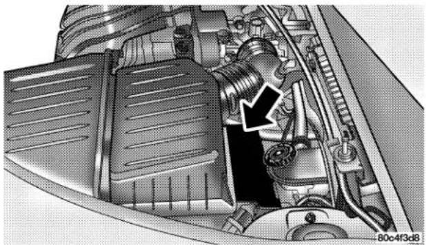
natural_image
Technical illustration of a mechanical assembly showing internal components and a highlighted section (no text or symbols)Power Distribution Center Location
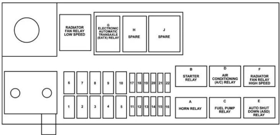
flowchart
graph TD
    A[" "] --> B["RADIATOR FAN RELAY LOW SPEED"]
    B --> C["G ELECTRONIC AUTOMATIC TRANSAXLE (EATX) RELAY"]
    C --> D["H SPARE"]
    C --> E["J SPARE"]
    F[" "] --> G["6"]
    F --> H["7"]
    F --> I["8"]
    F --> J["9"]
    F --> K["10"]
    F --> L["17"]
    F --> M["18"]
    F --> N["19"]
    F --> O["20"]
    F --> P["21"]
    F --> Q["22"]
    R[" "] --> S["1"]
    R --> T["2"]
    R --> U["3"]
    R --> V["4"]
    R --> W["5"]
    R --> X["11"]
    R --> Y["12"]
    R --> Z["13"]
    R --> AA["14"]
    R --> AB["15"]
    R --> AC["16"]
    AD["B STARTER RELAY"] --> AE["D AIR CONDITIONING (A/C) RELAY"] --> AF["F RADIATOR FAN RELAY HIGH SPEED"]
    AG["A HORN RELAY"] --> AH["C FUEL PUMP RELAY"] --> AI["E AUTO SHUT DOWN (ASD) RELAY"]
809cc391
Power Distribution Center
294 MAINTAINING YOUR VEHICLE
| FUSE Amp/Color Items | Fused | |
| 1 30 Amp/ | Pink Ignition Start | |
| 2 40 Amp/ | Green | Anti-Lock Brake (ABS) Pump |
| 3 40 Amp/ | Green | Ignition Run |
| 4 30 Amp/ | Blue Heated Seats | |
| 5 40 Amp/ | Green | Radiator Fan (Low Speed Turbo only) |
| 6 50 Amp/ | Red High Speed | Radiator Fan (Turbo Only) |
| 7 30 Amp/ | Blue Anti-Lock | Brake (ABS) Solenoid |
| 8 40 Amp/ | Green | Electric Back Light (EBL) |
| 9 40 Amp/ | Green | Power Top |
| 10 40 Amp/Green | IP Fuse Block | |
| 11 10 Amp/Red Air Conditioning (A/C) | ||
| 12 15 Amp/Lt.Blue | Stop Lights | |
| 13 20 Amp/Yellow | Fuel Pump/Auto Shut Down (ASD) | |
| 14 15 Amp/Lt.Blue | Horn | |
| 15 20 Amp/Yellow | Electronic Automatic Transaxle (ETAX) | |
| 16 | ||
| 17 15 Amp/Lt.Blue | Hi Beam | |
| 18 30 Amp/Blue Ignition Off Draw (IOD) | ||
| 19 15 Amp/Lt.Blue | Hazard Flasher | |
| 20 20 Amp/Yellow | Power Outlets |
| 21 Spare | |
| 22 20 Amp/Yellow | Fog Lamps (Export Only) |
Interior Fuses
The fuse access panel is on the left side of the instrument panel next to the steering column. To remove the panel, pull it out, as shown. A label identifying the components and circuits is located on the inside of the cover.
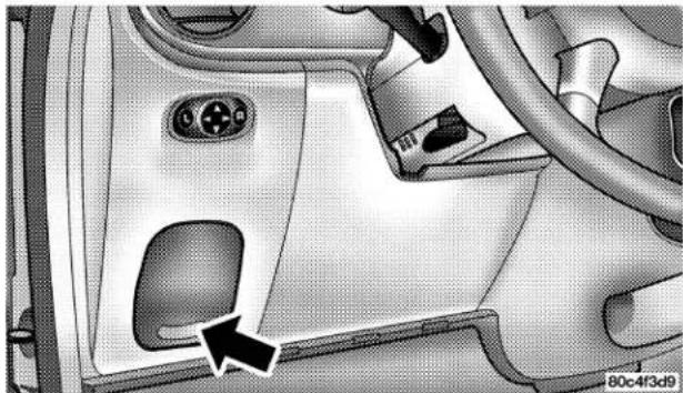
natural_image
Close-up of a car's side panel showing the dashboard and steering wheel (no text or symbols visible)Interior Fuse Panel
296 MAINTAINING YOUR VEHICLE
| FUSE Amp/Color Items | Fused | |
| 1 25 Amp/ Natural | Headlamp Switch | |
| 2 15 Amp/ Lt. Blue | Park Lamps | |
| 3 20 Amp/ Yellow | RKE/Door Locks | |
| 4 20 Amp/ Yellow | Power Height Adjust | |
| 5 10 Amp/ Red Airbag Run | Only | |
| 6 10 Amp/ Red B/U Electric Back Light (EBL) NEU SAF | ||
| 7 25 Amp/ Natural | HVAC Blower | |
| 8 15 Amp/ Lt. Blue | Fog Lamp (Non BUX) | |
| 9 10 Amp/ Red Airbag Run | -ST | |
| 10 10 Amp | /Red Cluster/RKE/SKIM | |
| 11 10 Amp | /Red Engine Module/ABS-TRAC | |
| 12 10 Amp | /Red PDC Relays/LDP | |
| 13 10 Amp | /Red Interior Lighting | |
| 14 20 Amp | /Yellow | Overhead Console/Radio |
| 15 20 Amp | /Yellow | Wipers/Comb. FLS |
| 16 10 Amp | /Red Auto Stick | /Ignition |
| 17 15 Amp | /Lt. Blue | Heated Seats |
| 18 10 Amp | /Red Heated Mirrors | |
| 19 10 Amp | /Red Rt Headlamp | |
| 20 10 Amp | /Red Lt Headlamp | |
CAUTION!
When replacing a blown fuse, it is important to use only a fuse having the correct amperage rating. The use of a fuse with a rating other than indicated may result in a dangerous electrical system overload. If a properly rated fuse continues to blow, it shows a problem in the circuit that must be corrected.
VEHICLE STORAGE
If you will not be using your vehicle for more than 21 days you may want to take steps to preserve your battery. You may:
- Disengage the mini fuse in the Power Distribution Center labeled IOD (Ignition Off-Draw).
- Or, disconnect the negative cable from the battery.
REPLACEMENT BULBS
LIGHT BULBS — Inside Bulb No.
ABS Indicator....LED
Airbag Indicator ..... L E D
Brake System Warning Indicator ..... L E D
Center Console Floor Lamp . . . . . . . . . . . . . . . . . T 3 7
Climate Controls 6 2 3 3 1 3 7
Console Gear Selector P C 1 9 4
Cruise Indicator . . . . . . . . . . . . . . . . . . . . . . . . . . . . . . . . . . . . . . . . . . . . . . . . V F D *
Deck Lid Ajar Indicator ..... L E D
Dome Light (Sport Bar Lights)....T 9 0 4
Door Ajar Indicator . . . . . . . . . . . . . . . . . . . . . . . . . . . . . . . . . . . . . . . . . . . . . . . . . . . V F D *
Front Fog Indicator ..... L E D
High Beam Indicator 74
Instrument Cluster Illumination 74
Low Fuel Indicator. . . . . . . . . . . . . . . . . . . . . . . . . . . . . . . . . . . . . . . . L E D
Low Oil Pressure Indicator ..... L E D
Overhead Reading Light (Rearview Mirror) . . . . T 1 9 2
Rear Cargo....T 9 0 6
Seat Belt Indicator ..... L E D
Security Alarm Indicator. L E D
Malfunction Indicator Light ..... L E D
Temperature Indicator ..... L E D
Trac (Active) Indicator . . . . . . . . . . . . . . . . . . . . . . . . . . . . . . . . . . . . . . . . . . . . . . . V F D *
TRAC OFF Indicator ..... L E D
Trip Indicator . . . . . . . . . . . . . . . . . . . . . . . . . . . . . . . . . . . . . . . . . . . . . . . . . . . . . . . . . V F D *
Turn Signal Indicator 103
Visor Vanity 74
Voltage Indicator ..... L E D
LIGHTS BULBS — Outside Bulb No.
Low Beam Headlight 9006XS
High Beam Headlight. 9005XS
Front Park/Turn Signal/Side Marker Light. 4157NAKX
Front Fog Light 9006
Center High Mounted Stop Light
(CHMSL) 921-W16W
Rear Tail/Stop/Turn Signal Light ..... 3157-P27/7W
Backup Light. 3157-P27/7W
License Light 168
NOTE: * Vacuum Fluorescent Display
All the inside bulbs are brass or glass wedge base.
Aluminum base bulbs are not approved and should not be used for replacement.
BULB REPLACEMENT
Headlight Bulb Replacement
CAUTION!
Do not touch the new headlight bulb with your fingers. Oil contamination will severely shorten bulb life.
- Remove the headlight access cover splash shield, located in the front wheel well opening.
- Disconnect the electrical connector.
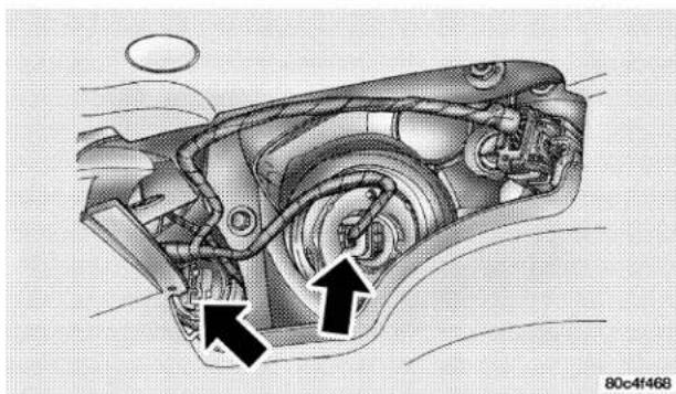
natural_image
Technical diagram of a car's internal engine and wheel assembly (no text or labels)- Rotate the socket to the left one quarter turn and replace the bulb.
300 MAINTAINING YOUR VEHICLE
Front Park/Turn Signal/Side Marker Lights
- Remove the headlight access cover splash shield, located in the front wheel well opening.
- Rotate the socket to the left one quarter turn to replace and replace the bulb.
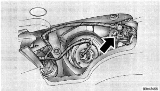
natural_image
Technical illustration of a mechanical assembly with an arrow indicating a specific component (no text or symbols present)Front Fog Lights — If Equipped
- Remove the fasteners attaching the lower splash shield to gain access to the fog light.
- Twist and remove the bulb from the fog light housing.
- Disconnect the electrical connector and replace bulb.
Tail/Stop, and Rear Turn Signal Lights
-
Remove the screw attaching the tail light housing and remove the housing from the vehicle.
-
Twist the bulb socket 1/4 turn to remove it from the housing.
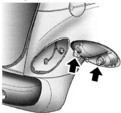
natural_image
Technical illustration of a mechanical component with two views and directional arrows indicating movement or assembly (no text or symbols present)80c4f469
- Pull the bulb out of the socket and replace.
Back Up Light Bulb
- Remove the screws attaching the back up light to the rear fascia and remove the housing.
- Remove the socket from the housing.
- Pull the bulb out of the socket and replace.
Center High Mounted Stop Light
- Open the deck lid and remove the deck lid CHMSL cover.
- Remove CHMSL lens from the housing by unlatching the two side latches.
- Pull the bulb out of the socket and replace.
302 MAINTAINING YOUR VEHICLE
FLUIDS AND CAPACITIES
| U.S. Metric | ||
| Fuel (Approximate) 15 Gallons 56.7 Liters | ||
| Engine Oil-With Filter | ||
| 2.4 Liter Engines (Use API Certified SAE 5W-30 Engine Oil.Refer to your engine oil filler cap for correct SAE grade meeting DaimlerChrysler Material Standard MS-6395.) | 5.0 qts 4.7 Liters | |
| Cooling System * | ||
| 2.4 Liter Engines (Mopar®Antifreeze/Coolant 5 Year/100,000 Miles Formula) | 6.5 qts 6.2 Liters | |
| * Includes heater and coolant recovery bottle filled to MAX level. | ||
RECOMMENDED FLUIDS, LUBRICANTS AND GENUINE PARTS
Engine
| Component Fluids, Lubricants and | Genuine Parts |
| Engine Coolant Mopar®Antifreeze/ | Coolant 5 Year/100,000 Mile Formula HOAT (Hybrid Organic Additive Technology) |
| Engine Oil Use API Certified SAE 5W | W-30 Engine Oil. Refer to your engine oil filler cap for correct SAE grade meeting DaimlerChrysler Material Standard MS-6395. |
| Engine Oil Filter | Non Turbo—Mopar 4105409 or equiv. Turbo—Mopar 4781452AA or equiv. |
| Spark Plugs Refer to the Vehicle Emission Control Information label in the engine compartment. | |
| Fuel Selection 91 Octane for High Output 2.4L Turbo and 87 Octane for 2.4L Standard Turbo and 2.4L Standard Non Turbo Engines. | |
304 MAINTAINING YOUR VEHICLE
Chassis
| Component Fluids, Lubricants and Genuine Parts. | |
| Automatic Transmission Fluid. Mopar® | ATF+4 Automatic Transmission Fluid. |
| Manual Transmission Fluid. Mopar®A | TF+4 Automatic Transmission Fluid. |
| Brake Master Cylinder Mopar®DOT 3, | SAE J1703 should be used. If DOT 3, SAE J1703 brake fluid is not available, then DOT 4 is acceptable. Use only recommended brake fluids. |
| Power Steering Reservoir Mopar®ATF | +4 Automatic Transmission Fluid. |
MAINTENANCE SCHEDULES
CONTENTS
■Emission Control System Maintenance ..... 3 0 6
■Maintenance Schedule....306
□ Schedule "B"—All Engines .....309
□ Schedule "A"—Non Turbo .....319
□ Schedule "A"—Turbo 323
306 MAINTENANCE SCHEDULES
The “Scheduled” maintenance services, listed in bold type must be done at the times or mileages specified to assure the continued proper functioning of the emission control system. These, and all other maintenance services included in this manual, should be done to provide best vehicle performance and reliability. More frequent maintenance may be needed for vehicles in severe operating conditions such as dusty areas and very short trip driving.
Inspection and service also should be done any time a malfunction is suspected.
NOTE: Maintenance, replacement, or repair of the emission control devices and systems on your vehicle may be performed by any automotive repair establishment or individual using any automotive part which has been certified pursuant to U.S. EPA or, in the State of California, California Air Resources Board regulations.
MAINTENANCE SCHEDULE
There are three maintenance schedules that show required service for your vehicle.
First is Schedule "B"—ALL ENGINES. It is for vehicles that are operated under the conditions that are listed below and at the beginning of the schedule.
• Day and night temperatures are below 32^ F ( 0^ C).
- Stop and go driving.
- Extensive engine idling.
- Driving in dusty conditions.
- Short trips of less than 10 miles (16 km).
- More than 50% of your driving is at sustained high speeds during hot weather, above 90° F (32° C).
- Trailer towing.†◇
- Taxi, police, or delivery service (commercial service).†◇
- Off-road or desert operation.
- If equipped for and operating with E-85 (ethanol) fuel.
NOTE: If ANY of these apply to you then change your engine oil every 3,000 miles (5 000 km) or 3 months, whichever comes first, and follow schedule "B—All Engines" of the "Maintenance Schedules" section of this manual.
NOTE: IF ANY of these apply to you then flush and replace the engine coolant every 102,000 miles (164,000 km) or 60 months, whichever comes first, and follow schedule "B—All Engines" of the "Maintenance Schedules" section of this manual.
NOTE: Most vehicles are operated under the conditions listed for Schedule "B"—ALL ENGINES.
Second is Schedule "A"—NON TURBO. It is for vehicles that are not operated under any of the conditions listed under Schedule "B"—ALL ENGINES.
Third is Schedule "A"—TURBO. It is for vehicles that are not operated under any of the conditions listed under Schedule "B"—ALL ENGINES.
Use the schedule that best describes your driving conditions. Where time and mileage are listed, follow the interval that occurs first.
CAUTION!
Failure to perform the required maintenance items may result in damage to the vehicle.
308 MAINTENANCE SCHEDULES
At Each Stop for Fuel
- Check the engine oil level about 5 minutes after a fully warmed engine is shut off. Checking the oil level while the vehicle is on level ground will improve the accuracy of the oil level reading. Add oil only when the level is at or below the ADD or MIN mark.
- Check the windshield washer solvent and add if required.
- Check tire pressure and look for unusual wear or damage.
- Inspect the battery and clean and tighten the terminals as required.
- Check the fluid levels of coolant reservoir, brake master cylinder and transaxle and add as needed.
Once a Month
- Check all lights and all other electrical items for correct operation.
- Check rubber seals on each side of the radiator for proper fit.
At Each Oil Change
- Change the engine oil filter.
- Inspect the exhaust system.
- Inspect the brake hoses.
- Inspect the CV joints and front suspension components.
- Check the automatic transaxle fluid level.
- Check the manual transaxle fluid level and fill plug condition.
- Check the coolant level, hoses, and clamps.
SCHEDULE "B"—ALL ENGINES
Follow schedule "B"—All Engines if you usually operate your vehicle under one or more of the following conditions.
Change the automatic transmission fluid and filter every 60,000 miles (96 000 km) if the vehicle is usually operated under one or more of the conditions marked with an ◇.
Change the manual transaxle fluid every 48,000 miles (77 000 km) if the vehicle is usually operated under one or more of the conditions marked with an †.
• Day and night temperatures are below 32^ F ( 0^ C).
- Stop and go driving.
- Extensive engine idling.
- Driving in dusty conditions.
- Short trips of less than 10 miles (16.2 km).
- More than 50% of your driving is at sustained high speeds during hot weather, above 90° F (32° C).
- Trailer towing.†◇
- Taxi, police, or delivery service (commercial service).†◇
- Off-road or desert operation.
- If equipped for and operating with E-85 (ethanol) fuel.
NOTE: If ANY of these apply to you then change your engine oil every 3,000 miles (5 000 km) or 3 months, whichever comes first, and follow schedule "B—All Engines" of the "Maintenance Schedules" section of this manual.
310 SCHEDULE "B"—ALL ENGINES
NOTE: IF ANY of these apply to you then flush and replace the engine coolant every 102,000 miles (164,000 km) or 60 months, whichever comes first, and follow schedule "B—All Engines" of the "Maintenance Schedules" section of this manual.
If none of these apply to you, and your vehicle is equipped with a Non-Turbo Charged Engine then change your engine oil at every interval shown on schedule "A"—NON TURBO in the maintenance schedule section of this manual.
If none of these apply to you, and your vehicle is equipped with a Turbo Charged Engine change your engine oil at every interval shown on schedule "A"—TURBO in the maintenance schedule section of this manual.
| Miles 3,000 6,000 9,000 12,000 15,000 18,000 (Kilometers) (5 000) (10 000) (14 000) (19 000) (24 000) (29 000) | ||||||
| Change engine oil and engine oil filter, if not replaced at 3 months. | X | X | X | X | X | |
| Rotate tires. X X X | ||||||
| Inspect the brake linings. X | ||||||
| Inspect the engine air cleaner filter, replace as necessary.* | X | |||||
| Inspect the Make-up air filter, replace as necessary. | X |
312 SCHEDULE "B"—ALL ENGINES
| Miles 21,000 24,000 27,000 30,000 33,000 36,000 (Kilometers) (34 000) (38 000) (43 000) (48 000) (53 000) (58 000) | ||||||
| Change engine oil and engine oil filter, if not replaced at 3 months. | X | X | X | X | X | |
| Rotate tires. X X X | ||||||
| Inspect the brake linings. X X | ||||||
| Replace the engine air cleaner filter. X | ||||||
| Replace the spark plugs. X | ||||||
| Inspect the tie rod ends and boot seals. | X | |||||
| Inspect the PCV valve and replace as necessary.* | X | |||||
| Replace the Make-up air filter. | X | |||||
| Adjust the generator drive belt tension. | X |
X
| Miles 39,000 42,000 45,000 48,000 51,000 54,000 (Kilometers) (62 000) (67 000) (72 000) (77 000) (82 000) (86 000) | ||||||
| Change engine oil and engine oil filter, if not replaced at 3 months. | X | X | X | X | X | |
| Rotate tires. X X X | ||||||
| Inspect the brake linings. X | ||||||
| Change the brake fluid. If vehicle is used for trailer towing. | X | |||||
| Inspect the engine air cleaner filter, replace as necessary.* | X | |||||
| Change the manual transaxle fluid.† X | ||||||
| Inspect the Make-up air filter. Replace as necessary. | X |
314 SCHEDULE "B"—ALL ENGINES
| Miles 57,000 60,000 63,000 66,000 69,000 72,000 (Kilometers) (91 000) (96 000) (101 000) (106 000) | (111 000) (115 000) | |||||
| Change engine oil and engine oil filter, if not replaced at 3 months. | X | X | X | X | X | |
| Rotate tires. X X X | ||||||
| Inspect the brake linings. | X | X | ||||
| Replace the engine air cleaner filter. | X | |||||
| Replace the spark plugs and ignition cables. | X | |||||
| Inspect the tie rod ends and boot seals. | X | |||||
| Inspect the PCV valve and replace if necessary. Not required if previously changed. * ‡ | X | |||||
| Replace the Make-up air filter. | X | |||||
| Adjust the generator drive belt tension. | X | |||||
| Change the automatic transaxle fluid and filter. ◇ | X | |||||
| Flush and replace engine coolant at 60 months, if not done at 102,000 miles. | X | |||||
| Miles 75,000 78,000 81,000 84,000 87,000 90,000 (Kilometers) (120 000) (125 000) (130 000) (135 000) (130 000) (144 000) | ||||||
| Change engine oil and engine oil filter, if not replaced at 3 months. | X | X | X | X | X | |
| Rotate tires. X X X | ||||||
| Inspect the brake linings. X | ||||||
| Inspect the engine air cleaner filter and replace as necessary.* | X | |||||
| Replace the engine air cleaner filter. X | ||||||
| Replace the spark plugs. X | ||||||
| Inspect the tie rod ends and boot seals. | X | |||||
| Inspect the PCV valve and replace if necessary. Not required if previously changed. * ‡ | X | |||||
| Replace the engine timing belt. * | X | |||||
| Inspect the Make-up air filter, replace as necessary. | X | |||||
| Adjust the generator drive belt tension. | X | |||||
| Replace the Make-up air filter. | X |
316 SCHEDULE "B"—ALL ENGINES
| Miles 93,000 96,000 99,000 102,000 105,000 (Kilometers) (150 000) (154 000) (159 000) (164 000) (168 000) | |||||
| Change engine oil and engine oil filter, if not replaced at 3 months. | X | X | X | X | X |
| Rotate tires. XX | |||||
| Inspect the brake linings. X | |||||
| Change the brake fluid. If vehicle is used for trailer towing. | X | ||||
| Inspect the engine air cleaner filter and replace as necessary.* | X | ||||
| Change the manual transaxle fluid.† X | |||||
| Flush and replace the engine coolant, if not replaced at 60 months. | X | ||||
| Inspect the Make-up air filter, replace as necessary. X | |||||
| Miles 108,000 111,000 114,000 117,000 120,000 (Kilometers) (173 000) (178 000) (183 000) (188 000) (193 000) | |||||
| Change engine oil and engine oil filter, if not replaced at 3 months. | X | X | X | X | X |
| Rotate tires. X X X | |||||
| Inspect the brake linings. X | |||||
| Replace the engine air cleaner filter. * | X | ||||
| Inspect the tie rod ends and boot seals. X | |||||
| Replace the Make-up air filter. X | |||||
| Adjust the generator drive belt tension. X | |||||
| Change automatic transaxle fluid and filter. ◇X | |||||
| Inspect the PCV valve and replace if necessary. *‡ | X | ||||
| Flush and replace the engine coolant at 120 months, if not replaced at 102,000 miles. | X | ||||
| Replace the spark plugs and ignition cables. | X |
318 SCHEDULE "B"—ALL ENGINES
* This maintenance is recommended by the manufacturer to the owner but is not required to maintain the emissions warranty.
‡ This maintenance is not required if previously replaced.
† This maintenance is required only for police, taxi, limousine type operation, or trailer towing.
◇ This maintenance is required only for police, taxi, limousine type operation, or trailer towing.
Inspection and service should also be performed anytime a malfunction is observed or suspected. Retain all receipts.
SCHEDULE "A"—NON TURBO
| Miles 6,000 12,000 18,000 24,000 30,000 36,000 (Kilometers) (10 000) (19 000) (29 000) (38 000) (48 000) (58 000) [Months] [6] [12] [18] [24] [30] [36] | ||||||
| Change engine oil and engine oil filter. X XXXXX | ||||||
| Rotate tires. X XXXXX | ||||||
| Inspect the brake linings. X X | ||||||
| Replace the engine air cleaner filter. | X | |||||
| Replace the spark plugs. | X | |||||
| Inspect the tie rod ends and boot seals. | X | |||||
| Replace the Make-up air filter. | X | |||||
| Adjust the generator drive belt tension | X |
| Miles 42,000 48,000 54,000 60,000 66,000(Kilometers) (67 000) (77 000) (86 000) (96 000) (106 000)[Months] [42] [48] [54] [60] [66] | |||||
| Change engine oil and engine oil filter. XXXXX | |||||
| Rotate tires. XXXXX | |||||
| Inspect the brake linings. X | |||||
| Replace the engine air cleaner filter. X | |||||
| Replace the spark plugs and ignition cables. X | |||||
| Inspect the tie rod ends and boot seals. X | |||||
| Inspect the PCV valve and replace, if necessary.* | X | ||||
| Flush and replace the engine coolant at 60 months, if not done at 102,000 miles. | X | ||||
| Replace the Make-up air filter. | X | ||||
| Adjust the generator drive belt tension. | X |
| Miles 72,000 78,000 84,000 90,000 96,000 102,000 (Kilometers) (115 000) (125 [Months] [72] [78] [84] [90] [96] [102] | 000) | (134 000) | (144 000) | (154 000) | (164 000) | |
| Change engine oil and engine oil filter. X X X X X X | ||||||
| Rotate tires. X X X X X X | ||||||
| Inspect the brake linings. X | X | |||||
| Replace the engine air cleaner filter. | X | |||||
| Replace the spark plugs. | X | |||||
| Inspect the tie rod ends and boot seals. | X | |||||
| Inspect the PCV valve and replace if necessary. Not required if previously changed. * ‡ | X | |||||
| Replace the Make-up air filter. | X | |||||
| Adjust the generator drive belt tension. | X | |||||
| Flush and replace the engine coolant, if not replaced at 60 months. | X |
322 SCHEDULE "A"—NON TURBO
| Miles 108,000 114,000 120,000(Kilometers) (173 000) (182 000) (192 000)[Months] [108] [114] [120] | |||
| Change engine oil and engine oil filter. X X X | |||
| Rotate tires. X X X | |||
| Inspect the PCV valve and replace if necessary. * ‡ X | |||
| Replace the air cleaner filter. X | |||
| Replace the engine timing belt. * X | |||
| Flush and replace the engine coolant at 120 months, if not done at 102,000 miles. | X | ||
| Replace the spark plugs and ignition cables. | X | ||
| Replace the Make-up air filter. | X |
* This maintenance is recommended by the manufacturer to the owner but is not required to maintain the emissions warranty.
‡ This maintenance is not required if previously replaced.
Inspection and service should also be performed anytime a malfunction is observed or suspected. Retain all receipts.
SCHEDULE "A"—TURBO
| Miles 5,000 10,000 15,000 20,000 25,000 30,000 (Kilometers) (8 000) (16 000) (24 000) (32 000) (40 Months) [6] [12] [18] [24] [30] [36] | 000) (48 000) | |||||
| Change engine oil and engine oil filter. X XXXXX | ||||||
| Rotate tires. X XXXXX | ||||||
| Inspect the brake linings. X | ||||||
| Replace the engine air cleaner filter. X | ||||||
| Replace the spark plugs. | X | |||||
| Inspect the tie rod ends and boot seals. | X | |||||
| Replace the Make-up air filter. | X | |||||
| Adjust the generator drive belt tension. | X |
324 SCHEDULE "A"—TURBO
| Miles 35,000 40,000 45,000 50,000 55,000(Kilometers) (56 000) (64 000) (72 000) (80 000) (88 000)[Months] [42] [48] [54] [60] [66] | |||||
| Change engine oil and engine oil filter. XXXXX | |||||
| Rotate tires. XXXXX | |||||
| Inspect the brake linings. X | |||||
| Flush and replace engine coolant at 60 months, if not replaced at 100,000 miles. | X |
| Miles 60,000 65,000 70,000 75,000 80,000 85,000 (Kilometers) (96 000) (104[Months] [72] [78] [84] [90] [96] [102] | 000) | (112 000) | (120 000) | (128 000) | (136 000) | |
| Change engine oil and engine oil filter. X X X | X | X | X | |||
| Rotate tires. X X X X X | X | |||||
| Inspect the brake linings. X | X | |||||
| Replace the engine air cleaner filter. | X | |||||
| Replace the spark plugs and ignition cables. | X | |||||
| Inspect the tie rod ends and boot seals. | X | |||||
| Inspect the PCV valve and replace if necessary. Not required if previously changed. * ‡ | X | |||||
| Replace the Make-up air filter. | X | |||||
| Adjust the generator drive belt tension. | X |
| Miles 90,000 95,000 100,000 105,000(Kilometers) (144 000) (156 000) (160 000) (168 000)[Months] [108] [114] [120] [126] | ||||
| Change engine oil and engine oil filter. X X X X | ||||
| Rotate tires. | X X X X | |||
| Inspect the brake linings. | X | |||
| Replace the engine air cleaner filter. | X | |||
| Replace the spark plugs. | X | |||
| Adjust the generator drive belt tension. | X | |||
| Inspect the tie rod ends and boot seals. | X | |||
| Inspect the PCV valve and replace if necessary. Not required if previously changed. * ‡ | X | |||
| Flush and replace the engine coolant if not done at 60 months. | X | |||
| Replace the Make-up air filter. | X | |||
| Replace the engine timing belt. | X |
| Miles 110,000 115,000 120,000(Kilometers) (177 000) (185 000) (193 000)[Month] [132] [138] [144] | |||
| Change engine oil and engine oil filter. X X X | |||
| Rotate tires. X X X | |||
| Inspect the PCV Valve and replace if necessary. * X | |||
| Replace the engine air cleaner filter. X | |||
| Replace the spark plugs and ignition cables. X |
* This maintenance is recommended by the manufacturer to the owner but is not required to maintain the emissions warranty.
‡ This maintenance is not required if previously replaced.
Inspection and service should also be performed anytime a malfunction is observed or suspected. Retain all receipts.
WARNING!
You can be badly injured working on or around a motor vehicle. Do only that service work for which you have the knowledge and the right equipment. If you have any doubt about your ability to perform a service job, take your vehicle to a competent mechanic.
IF YOU NEED CONSUMER ASSISTANCE
CONTENTS
■Suggestions For Obtaining Service For Your Vehicle....3 3 0
□Prepare For The Appointment....3 3 0
□Prepare A List....3 3 0
□Be Reasonable With Requests....3 3 0
■If You Need Assistance....3 3 1
■Warranty Information....3 3 3
■Mopar®Parts 3 3 5
■Reporting Safety Defects....3 3 5
□In Canada 335
■ Publication Order Forms ....336
■Department Of Transportation Uniform Tire Quality Grades 3 3 7
□Treadwear....3 3 7
□Traction Grades....3 3 7
□Temperature Grades 3 3
SUGGESTIONS FOR OBTAINING SERVICE FOR YOUR VEHICLE
Prepare For The Appointment
If you're having warranty work done, be sure to have the right papers with you. Take your warranty folder. All work to be performed may not be covered by the warranty, discuss additional charges with the service manager. Keep a maintenance log of your vehicle's service history. This can often provide a clue to the current problem.
Prepare A List
Make a written list of your vehicle's problems or the specific work you want done. If you've had an accident, or work done that is not on your maintenance log, let the service advisor know.
Be Reasonable With Requests
If you list a number of items, and you must have your vehicle by the end of the day, discuss the situation with the service advisor and list the items in order of priority. At many dealers you may obtain a rental vehicle at a minimal daily charge. If you need a rental, it is advisable to make these arrangements when you call for an appointment.
IF YOU NEED ASSISTANCE
The manufacturer and its dealers are vitally interested in your satisfaction. We want you to be happy with our products and services.
Warranty service must be done by an authorized Chrysler, Dodge, or Jeep dealer. We strongly recommend that you take your vehicle to you selling dealer. They know you and your vehicle best, and are most concerned that you get prompt and high quality service. The manufacturer's dealers have the facilities, factory-trained technicians, special tools, and the latest information to assure your vehicle is fixed correctly and in a timely manner.
This is why you should always talk to your dealer's service manager first. Most matters can be resolved with this process.
- If for some reason you are still not satisfied, talk to the general manager or owner of the dealership. They want to know if you need assistance.
- If your dealership is unable to resolve the concern, you may contact the Manufacturer's Customer Center.
Any communication to the Manufacturer's Customer Center should include the following information:
- Owner's name and address
- Dealership name
• Vehicle identification number
• Vehicle delivery date and mileage
- Owner's telephone number (home and office)
332 IF YOU NEED CONSUMER ASSISTANCE
DaimlerChrysler Motors Corporation Customer Center
P.O. Box 21-8004
Auburn Hills, MI 48321-8004
Windsor, Ontario N9A 4H6
Phone —(800) 465–2001
In Mexico contact:
In Mexico (915) 729–1248 or 729–1240
Outside Mexico (525) 729–1248 or 729–1240
Customer Assistance For The Hearing Or Speech Impaired (TDD/TTY)
To assist customers who have hearing difficulties, the manufacturer has installed special TDD (Telecommunication Devices for the Deaf) equipment at its Customer Center. Any hearing or speech impaired customer who has access to a TDD or a conventional teletypewriter (TTY) in the United States can communicate with the manufacturer by dialing 1–800–380–CHRY.
Service Contract
You may have purchased a service contract for your vehicle to help protect you from the high cost of unexpected repairs after your manufacturer's new vehicle limited warranty expires. The manufacturer stands behind only the manufacturer's Service Contracts. If you purchased a manufacturer's Service Contract, you will receive Plan Provisions and an Owner Identification Card in the mail within three weeks of your vehicle delivery date. If you have any questions about your service
contract, call the manufacturer's Service Contract National Customer Hotline at 1-800-521-9922.
The manufacturer will not stand behind any service contract that is not the manufacturer's Service Contract. It is not responsible for any service contract other than the manufacturer's Service Contract. If you purchased a service contract that is not a manufacturer's Service Contract, and you require service after your manufacturer's new vehicle limited warranty expires, please refer to your contract documents, and contact the person listed in those documents.
We appreciate that you have made a major investment when you purchased your new vehicle. Your dealer has
also made a major investment in facilities, tools, and training to assure that you are absolutely delighted with your ownership experience. You'll be pleased with their sincere efforts to resolve any warranty issues or related concerns.
WARRANTY INFORMATION
See your manufacturer's Warranty Information Booklet for information on warranty coverage and transfer of warranty.
334 IF YOU NEED CONSUMER ASSISTANCE
| DESCRIPTION | 1 Yr/ 12,000 | 2 Yr/ 24,000 | 3 Yr/ 36,000 | 3 Yr/ 50,000 | 3 Yr/ Unlmtd | 5 Yr/ 100,000 | 7 Yr/ 70,000 | 8 Yr/ 80,000 |
| Basic Limited Warranty Coverage | ||||||||
| Special Extended Warranty Coverage | ||||||||
| Powertrain Limited Warranty ($100 deductible) | 1st Owner & 2nd Owner with Paid Powertrain Transfer | |||||||
| 2nd Owner if Powertrain Not Transferred and 3rd (And After) Owners | ||||||||
| Anti-Corrosion Perforation Limited Warranty: All Panels | ||||||||
| Outer Panels | ||||||||
| Federal Emission Warranty | ||||||||
| Federal Emission Warranty - Specified Components | ||||||||
| California Emission Warranty | ||||||||
| California Emission Warranty - Specified Components | ||||||||
NOTE: Vehicles used as a police vehicle, taxi, limousine, postal delivery vehicle, ambulance or rental vehicle are covered only under the 3 year/36,000 mile Basic Limited Warranty.
8132c269
U.S. ONLY
MOPAR®PARTS
Mopar® fluids, lubricants, parts, and accessories are available from your dealer. They will help you keep your vehicle operating at its best.
REPORTING SAFETY DEFECTS
In the 50 United States and Washington D.C.: If you believe that your vehicle has a defect which could cause a crash or cause injury or death, you should immediately inform the National Highway Traffic Safety Administration (NHTSA) in addition to notifying the manufacturer.
If NHTSA receives similar complaints, it may open an investigation, and if it finds that a safety defect exists in a group of vehicles, it may order a recall and remedy campaign. However, NHTSA cannot become involved in individual problems between you, your dealer, and the manufacturer.
To contact NHTSA, you may either call the Auto Safety Hotline toll free at 1-800-424-9393 (or 366-0123 in Washington DC area) or write to: NHTSA, U.S. Dept. of Transportation, Washington DC 20590. You can also obtain other information about motor vehicle safety from the Hotline.
In Canada:
If you believe that your vehicle has a safety defect, you should contact the Customer Service Department immediately. Canadian customers who wish to report a safety defect to the Canadian government should write to Transport Canada, Motor Vehicle Defect Investigations and Recalls, 2780 Sheffield Road, Ottawa, Ontario K1B 3V9.
PUBLICATION ORDER FORMS
To order the following manuals, you may use either the website or the phone numbers listed below. Visa, Mastercard, American Express, and Discover orders are accepted. If you prefer mailing your payment, please call for an order form.
NOTE: A street address is required when ordering manuals. (No P.O. Boxes).
• Service Manuals.
These comprehensive service manuals provide the information that students and professional technicians need in diagnosing/troubleshooting, problem solving, maintaining, servicing and repairing DaimlerChrysler Corporation vehicles. A complete working knowledge of the vehicle, system and/or components is written in straightforward language with illustrations, diagrams and charts.
• Diagnostic Procedure Manuals.
Filled with diagrams, charts and detailed illustrations, these practical manuals make it easy for students and technicians to find and fix problems on computer-controlled vehicle systems and features. They show exactly how to find and correct problems the first time, using step-by-step troubleshooting and driveability procedures, proven diagnostic tests and a complete list of all tools and equipment.
- Owner's Manuals.
These manuals have been prepared with the assistance of service and engineering specialists to acquaint you with specific Chrysler group vehicles. Included are starting, operating, emergency and maintenance procedures as well as specifications, capabilities and safety tips.
Call Toll Free at 1-800-890-4038 (U.S.) or 1-800-387-1143 (Canada)
Or
Visit us on the World Wide Web at:
www.techauthority.daimlerchrysler.com or www.daimlerchrysler.ca/manuals
DEPARTMENT OF TRANSPORTATION UNIFORM TIRE QUALITY GRADES
The following describes the tire grading categories established by the National highway Traffic Safety Administration. The specific grade rating assigned by the tire's manufacturer in each category is shown on the sidewall of the tires on your car.
All Passenger Car Tires Must Conform to Federal Safety Requirements in Addition to These Grades.
Treadwear
The treadwear grade is a comparative rating based on the wear rate of the tire when tested under controlled conditions on a specified government test course. For example, a tire graded 150 would wear one and a half (1 1/2) times as well on the government course as a tire graded 100. The relative performance of tires depends upon the actual conditions of their use, however, and may depart significantly from the norm due to variations in driving habits, service practices and differences in road characteristics and climate.
Traction Grades
The traction grades, from highest to lowest, are A, B, and C, and they represent the tire's ability to stop on wet pavement as measured under controlled conditions on specified government test surfaces of asphalt and concrete. A tire marked C may have poor traction performance.
WARNING!
The traction grade is based on braking (straight-ahead) traction tests and does not include cornering (turning) performance.
Temperature Grades
The temperature grades are A (highest), B, and C, representing the tire's resistance to the generation of heat and its ability to dissipate heat when tested under controlled conditions on a specified indoor laboratory test wheel. Sustained high temperature can cause the material of the tire to degenerate and reduce tire life, and excessive temperature can lead to sudden tire failure. The grade C corresponds to a level of performance which all passenger car tires must meet under the Federal Motor Vehicle Safety Standard No. 109. Grades B and A represent higher levels of performance on the laboratory test wheel than the minimum required by law.
WARNING!
The temperature grade is established for a tire that is properly inflated and not overloaded. Excessive speed, underinflation, or excessive loading, either separately or in combination, can cause heat buildup and possible tire failure.
INDEX
ABS (Anti-Lock Brake) System ..... 198
Adding Engine Coolant (Antifreeze) ..... 2 7 4
Adding Fuel 225
Adding Washer Fluid 100
Additives, Fuel 2 2 3
Air Cleaner, Engine (Engine Air Cleaner Filter) . . . 264
Air Conditioner Maintenance....267
Air Conditioning Controls 169
Air Conditioning, Operating Tips ..... 1 7 4
Air Conditioning Refrigerant....267,268
Air Conditioning System 169,267
Air Pressure, Tires....2 1 1
Airbag 40
Airbag Deployment 46
Airbag Light 44,48,58,132
Airbag Maintenance 48
Airbag, Side 46
Alarm, Panic 22
Alarm System 25,127
Alignment and Balance 218
Alterations/Modifications, Vehicle ..... 7
Antifreeze (Engine Coolant) ..... 273,302,303
Capacities 302
Anti-Lock Brake System (ABS) 198
Anti-Lock Warning Light 129
Anti-Theft Security Alarm 25
Appearance Care 284
Auto Down Power Windows 29
Automatic Door Locks 20
Automatic Transaxle 12,182,185,280
Fluid and Filter Changes 283
Fluid Level Check....281
Interlock System....18,186
Reset Mode 187
Selection Of Lubricant 280
Shifting 187
Special Additives 283
Autostick....134,190
INDEX 341
Back-Up Lights 301
Ball Joints 268
Battery 265
Keyless Transmitter Replacement ..... 2 4
Belts, Drive 261
Belts, Engine 264
Body Mechanism Lubrication....269
Boot, Convertible Top ..... 68,72
B-Pillar Location 206
Brake Fluid 304
Brake, Parking 195
Brake System 197,278
Anti-Lock....198
Hoses 278
Master Cylinder 279
Parking....195
Warning Light 130
Brakes....197,278
Brake/Transmission Interlock 186
Break-In Recommendations, New Vehicle ..... 5 6
Bulb Replacement....297,299
Bulbs, Light 297
Calibration, Compass 78
Capacities, Antifreeze (Engine Coolant) ..... 302
Capacities, Fluid 302
Caps, Filler
Fuel 225
Oil (Engine) 252,253,260
Radiator (Coolant Pressure) 275
Carbon Monoxide Warning 2 2 4
Cassette Tape and Player Maintenance ..... 1 6 7
Cassette Tape Player....136,146,149
Catalytic Converter 262
Caution, Exhaust Gas 57
CD Changer 145,151,157
CD Player 142,153,155,159,162
CD Player Maintenance 16
Cellular Phone 168
Center High Mounted Stop Light ..... 3 0 1
Central Door Locks 20
Chains, Tire 219
Changing A Flat Tire....235
Chart, Tire Sizing....203
Check Engine Light (Malfunction Indicator Light) . 255
Child Restraint 49
Child Restraint Tether Anchors ..... 5 3
Child Seat 54
Clean Air Gasoline 222
Climate Control 169
Clock....134
Coin Holder 11 5
Compact Disc Maintenance....168
Compact Disc Player 136,142
Compact Spare Tire 214
Compass 75
Compass Calibration 78
Compass Variance 77
Console....11 5
Contract, Service 3 3 2
Convertible....62
Convertible Boot 68,72
Convertible Top 62
Convertible Top Maintenance....290
Convertible Top Manual Override ..... 73,247
Cool Down, Turbo 184
Coolant....302,303
Coolant Pressure Cap 275
Cooling System 272
Adding Coolant (Antifreeze) 274
Coolant Level 272,275
Disposal of Used Coolant 275
Drain, Flush, and Refill 273
Inspection 275
Points to Remember 276
Pressure Cap 275
INDEX 343
Radiator Cap 275
Selection of Coolant 273
Corrosion Protection 284
Crankcase Emission Control System ..... 2 6 4
Cruise Light 132
Cup Holder 115
Customer Assistance....3 3 1
Dealer Service 256
Deck Lid 26
Deck Lid, Emergency Release 28
Deck Lid, Power Release 27
Defroster, Rear Window ..... 1 7 6
Defroster, Windshield 58,171
Delay (Intermittent) Wipers 9 9
Diagnostic System, Onboard 254
Dimmer Switch, Headlight 97
Disposal
Engine Oil 261
Door Ajar....131
Door Locks 18
Door Locks, Automatic ..... 2 0
Door Opener, Garage 106
Downshifting....194
Drive Belts 261
Driving
On Slippery Surfaces 243
Electric Rear Window Defrost 176
Electric Remote Mirrors 79
Electrical Power Outlets 1 1 2
Electronic Power Distribution Center ..... 2 9 2
Electronic Speed Control 103
Emergency Deck Lid Release....2 8
Emergency, In Case of
Jacking 235
Jump Starting 240
Towing 245
Emission Control System Maintenance ..... 255,306
Engine 252,253
Break-In Recommendations....56
Checking Oil Level 257
Exhaust Gas Caution 2 2 4
Fuel Requirements 221
Jump Starting 240
Oil 257,302,303
Oil Change Interval 258
Oil Filler Cap 252,253,260
Oil Filter 303
Oil Selection 260
Oil Synthetic 260
Overheating 233
Temperature Gauge....128
Timing Belt 264
Exhaust Gas Caution 27,57,224,271
Exhaust System 271
Filler Location Fuel 134
Filters
Air Cleaner 264
Engine Fuel 264
Engine Oil 261,303
Flashers 232
Hazard Warning 232
Flat Tire Stowage 240
Flooded Engine Starting 183
Fluid, Brake 304
Fluid Capacities 302
Fluid Leaks 58
Fluid Level Checks
Automatic Transaxle 281
Fluids 303
Fog Light Service 300
Fog Lights 97,133
Folding Rear Seat 87
Freeing A Stuck Vehicle 244
INDEX 345
Fuel 221,303
Adding 225
Additives....2 2 3
Capacity 302
Clean Air 222
Filler Cap 134,225
Filler Door....134
Filter 264
Gasoline 221
Gauge....127
Hoses 277
Light 133
Octane Rating 2 2 1
Requirements 2 2 1
System Hoses 277
Tank Capacity 302
Fueling 225
Fuses 292
Garage Door Opener....106
Gas Cap 225
Gasoline 221,302
Gasoline, Clean Air 2 2 2
Gasoline, Reformulated 222
Gauges
Coolant Temperature 128
Fuel 127
Tachometer....129
Gearshift 187
General Information 17,23
General Maintenance 257
Glass Cleaning 289
Hazard Warning Flasher 232
Head Restraints 85
Headlights
Bulb Replacement....299
Cleaning 289
346 INDEX
High Beam....97,129
High Beam/Low Beam Select Switch ..... 9 7
Passing....97
Switch 96
Heated Seats....86
Homelink Transmitter 106
Hood Release....93
Hoses 277
Ignition....12
Key
Wiring System 262
Immobilizer....14,26
Indicator, Traction Control ..... 131,132
Infant Restraint 50
Inside Rearview Mirror 75
Instrument Cluster 124,127
Instrument Panel and Controls 123
Instrument Panel Cover 289
Instrument Panel Lens Cleaning 289
Integrated Power Module 292
Interior Appearance Care 288
Interior Fuses 295
Interior Lights 94
Intermittent Wipers 9 9
Introduction 4
Jack Location 235
Jack Operation 235,238
Jump Starting 240
Key, Programming 16
Key Release Button 13
Key, Replacement 16
Key, Sentry 14
Key-In Reminder 14
Keyless Entry System 21
Keys 12
INDEX 347
Knee Bolster 44,46
Lane Change and Turn Signals ..... 1 2 8
Lap/Shoulder Belts....3 1
Latches
Hood 93
Lead Free Gasoline....2 2 1
Light Bulbs 297,299
Lights....58,94
Airbag....44,48,58,132
Anti-Lock 129
Back-Up 301
Brake Warning....130
Center Mounted Stop 301
Daytime Running 96
Deck Lid Ajar 127
Dimmer Switch, Headlight 95
Engine Temperature Warning....128
Fog 97,133,300
Front Replacement 299
Headlight Switch 96
Headlights 96
High Beam Indicator 129
Instrument Cluster 96
Interior 94
Lights On Reminder 96
Low Fuel 133
Malfunction Indicator 133
Oil Pressure....127
Rear Servicing 300
Seat Belt Reminder....129
Security Alarm 25
Service....299
Theft Alarm 127
Traction Control 131,132,201
Turn Signal....95,97,128,300
Voltage 127
Warning (Instrument Cluster Description) ..... 1 2
348 INDEX
Loading Vehicle....2 2 7
Tires 20
Locks
Central 20
Door 18
Power Door....19
Steering Wheel 17
Lubrication, Body 269
Maintenance Free Battery 265
Maintenance, General 257
Maintenance Procedures 257
Maintenance Schedule
Schedule "A"-Non Turbo 319
Schedule "A"-Turbo 323
Schedule "B" 309
Schedule "B"-All Engines 309
Maintenance Schedules 306
Malfunction Indicator Light 133,255
Manual Override, Convertible Top ..... 73,247
Manual, Service 3 3 6
Manual Transaxle....182,191,284
Downshifting....194
Fluid Level Check 284
Frequency of Fluid Change 284
Lubricant Selection 284
Master Cylinder 279
Mirrors 75
Compass/Temperature 75
Electric Remote 79
Outside 78
Rearview 75
Vanity 80
Modifications/Alterations, Vehicle 7
Mopar Parts 256,335
Multi-Function Control Lever 95
Navigation System 166
INDEX 349
New Vehicle Break-In Period ..... 5 6
Occupant Restraints 30
Octane Rating, Gasoline 2 2 1
Odometer....131
Trip 131,134
Oil, Engine 257,302
Capacity 302
Change Interval 258
Checking 257
Disposal 261
Filter 261
Identification Logo 260
Materials Added to 261
Quality 260
Recommendation 260,302
Synthetic 260
Viscosity 260
Oil Pressure Light 127
Onboard Diagnostic System 254,255
Opener, Garage Door 106
Operator Manuals (Owner's Manuals) ..... 4
Outside Air Intake 175
Overdrive 189
Overheating, Engine 233
Owner's Manual 4,336
Paint Care 284
Panic Alarm 2 2
Parking Brake 195
Passing Light 97
Pets 56
Placard, Tire and Loading Information ..... 207
Power
Deck Lid Release 27
Distribution Center 292
Door Locks 19
Outlet 112
Steering 199,268
Steering, Checking 268
Windows 28
Power Steering Fluid 304
Pregnant Women and Seat Belts 39
Pretensioners
Seat Belts 39
Programmable Electronic Features ..... 107,111
Programming Transmitters....23,107,111
Radial Ply Tires 214
Radiator Cap (Coolant Pressure Cap) ..... 2 7 5
Radio Broadcast Signals 135
Radio Operation....147,153,168
Radio (Sound Systems) ..... 136,146,153,159
Rear Seat, Folding 87,88
Rear Window Defroster 176
Reclining Front Seats 82
Recommended Fluids, Lubricants and Genuine
Parts 303
Refrigerant 26 8
Remote Keyless Entry 21
Replacement Bulbs 29 7
Replacement Keys 16
Replacement Parts 256
Replacement Tires 21 7
Reporting Safety Defects 335
Restraints, Child 49,54
Restraints, Infant 50
Rotation, Tires 2 2 0
Safety Checks Inside Vehicle 57
Safety Checks Outside Vehicle 58
Safety Defects, Reporting 335
Safety Information, Tire 2 01
Safety Tips 57
Schedule, Maintenance 306
INDEX 351
Seat Belts 30
And Pregnant Women....39
Child Restraint 49
Cleaning 290
Front Seat....3 1
Pretensioners....39
Rear Seat 31
Reminder 129
Untwisting Procedure 37
Seats 80
Adjustment 80
Head Restraints 85
Heated....86
Height Adjustment 81
Rear Folding 87,88
Reclining 82
Seatback Release 82,83
Tilting....82,83
Security Alarm (Theft Alarm) 2 5
Sentry Key 14,26
Sentry Key Programming....16
Service and Maintenance....306
Service Assistance 330,331
Service Contract 332
Service Manuals 336
Setting the Clock....134
Severe Service 309
Shift Speeds, Manual Transaxle 194
Shoulder Belts 31
Side Airbag 46
Side Window Demisters....176
Slippery Surfaces, Driving On 243
Snow Tires 219
Spare Tire 214,215,236
Spark Plugs 262
Speed Control 103,132
Speedometer 129
Speedometer and Odometer 124
352 INDEX
Starting 182
Automatic Transmission....182
Engine Fails to Start . . . . . . . . . . . . . . . . . . . . . 1 8 3
Manual Transmission 182
Starting Procedures....182
Steering
Power 199,268
Tilt Column....101
Wheel Lock....17
Storage....1 16,297
Storage Bin 116
Stuck, Freeing 244
Supplemental Restraint System - Airbag ..... 4 0
Synthetic Engine Oil 260
System, Navigation 166
Tachometer 129
Temperature Gauge, Engine Coolant ..... 128,234
Tether Anchor, Child Restraint ..... 5 3
Theft Alarm 25
Theft System 25
Tilt Steering Column 101
Tire and Loading Information Placard ..... 206,207
Tire Identification Number (TIN) 205
Tire Markings 201
Tire Safety Information 201
Tires 58,210,337
Air Pressure 210
Alignment 218
Chains 219
Changing 235
Compact Spare 214
Flat Changing 240
General Information 210
High Speed 213
Inflation Pressures 211
Jacking 235
Load Capacity 206,207
Quality Grading 337
Radial 214
Replacement 217
Rotation....2 2 0
Safety 201,210
Sizes 203
Snow Tires....219
Spare Tire 236
Spinning 216
Tread Wear Indicators 216
Top Cover 68
Towing
Disabled Vehicle 245
Traction 243
Traction Control....102,131,132,200
Traction Control Switch 102,200
Trailer Towing 227
Minimum Requirements....2 2 8
Trailer and Tongue Weight....2 2 8
Warnings 227
Transaxle....185
Automatic....12,182,185,280
Autostick....190
Manual....13,182,191
Operation 185
Overdrive....189
Selection of Lubricant 280
Transmitter Battery Service 24
Transmitter, Garage Door Opener ..... 1 0 6
Transmitter Programming 23
Transmitter, Remote Keyless Entry ..... 2 1
Transporting Pets 56
Tread Wear Indicators 216
Trip Odometer Reset Button ..... 131,134
Trunk Lid (Deck Lid) 2 6
Turbo Cool Down....184
Turn Signals 97,128
354 INDEX
Understanding Your Instrument Panel ..... 1 2 3
Uniform Tire Quality Grades ..... 3 3 7
Universal Transmitter....106
Unleaded Gasoline 2 2 1
Untwisting Procedure, Seat Belt ..... 3 7
Vacuum/Vapor Harnesses 277
Vanity Mirrors 80
Variance, Compass....7 7
Vehicle Identification Number 6
Vehicle Loading 207,227
Vehicle Modifications/Alterations 7
Vehicle Storage 297
Vehicle Theft Alarm 25
Warning, Door Ajar ..... 1 3 1
Warning Lights (Instrument Cluster Description) . 127
Warnings and Cautions 6
Warranty Information 3 3 3
Washer, Adding Fluid . . . . . . . . . . . . . . . . . . . . . . . . 1 0 0
Washers, Windshield 98
Washing Vehicle 285
Wheel Alignment and Balance 2 1 8
Wheel and Wheel Trim Care 287
Window Fogging 175
Windows 28
Windshield Washers 98
Windshield Wipers 98,269
Wiper Blade Replacement 269
Wipers, Intermittent 9 9
NOTES
NOTES
NOTES
NOTES
NOTES
NOTES
- INTRODUCTION
- INTRODUCTION
- WARNING!
- HOW TO USE THIS MANUAL
- INTRODUCTION
- WARNINGS AND CAUTIONS
- VEHICLE IDENTIFICATION NUMBER
- VEHICLE MODIFICATIONS / ALTERATIONS
- THINGS TO KNOW BEFORE STARTING YOUR VEHICLE
- CONTENTS
- THINGS TO KNOW BEFORE STARTING YOUR VEHICLE
- THINGS TO KNOW BEFORE STARTING YOUR VEHICLE 11
- THINGS TO KNOW BEFORE STARTING YOUR VEHICLE
- A WORD ABOUT YOUR KEYS
- Ignition Key Removal
- Automatic Transaxle
- THINGS TO KNOW BEFORE STARTING YOUR VEHICLE 13
- Manual Transaxle
- THINGS TO KNOW BEFORE STARTING YOUR VEHICLE
- CAUTION!
- Locking Doors With The Key
- Key-In-Ignition Reminder
- SENTRY KEY
- NOTE:
- Replacement Keys
- Sentry Key Programming
- General Information
- STEERING WHEEL LOCK — IF EQUIPPED
- If You Wish To Manually Lock The Steering Wheel:
- To Release The Steering Wheel Lock:
- THINGS TO KNOW BEFORE STARTING YOUR VEHICLE
- Automatic Transaxle Ignition Interlock System
- DOOR LOCKS
- Manual Door Locks
- Power Door Locks
- THINGS TO KNOW BEFORE STARTING YOUR VEHICLE
- Central Locking/Unlocking
- Automatic Door Locks
- REMOTE KEYLESS ENTRY
- To Unlock The Doors:
- THINGS TO KNOW BEFORE STARTING YOUR VEHICLE
- To Lock The Doors:
- Horn Chirp Feature
- Using The Panic Alarm:
- To Program Transmitters
- THINGS TO KNOW BEFORE STARTING YOUR VEHICLE
- Transmitter Battery Service
- SECURITY ALARM SYSTEM
- To set the alarm:
- THINGS TO KNOW BEFORE STARTING YOUR VEHICLE
- To disarm the system:
- Tamper Alert
- Security System Manual Override
- DECK LID
- Power Deck Lid Release
- EMERGENCY DECK LID RELEASE LATCH
- POWER WINDOWS
- Auto Down Feature
- Wind Buffeting
- OCCUPANT RESTRAINTS
- Lap/Shoulder Belts
- THINGS TO KNOW BEFORE STARTING YOUR VEHICLE
- THINGS TO KNOW BEFORE STARTING YOUR VEHICLE 33
- Lap/Shoulder Belt Operating Instructions
- THINGS TO KNOW BEFORE STARTING YOUR VEHICLE
- THINGS TO KNOW BEFORE STARTING YOUR VEHICLE
- Seat Belt Webbing Guide
- THINGS TO KNOW BEFORE STARTING YOUR VEHICLE 37
- Lap/Shoulder Belt Untwisting Procedure
- THINGS TO KNOW BEFORE STARTING YOUR VEHICLE
- Seat Belt Pretensioners
- Seat Belts And Pregnant Women
- THINGS TO KNOW BEFORE STARTING YOUR VEHICLE
- Driver and Front Passenger Supplemental Restraint System (SRS) - Airbag
- THINGS TO KNOW BEFORE STARTING YOUR VEHICLE
- THINGS TO KNOW BEFORE STARTING YOUR VEHICLE
- The front airbag system consists of the following:
- The Side Airbag System, on vehicles equipped, consists of the following:
- How The Front Airbag System Works
- AIR BAG
- Side Airbags Supplemental Restraint System (SRS)—If Equipped
- If A Deployment Occurs
- Maintaining Your Airbag System
- Airbag Light
- Child Restraint
- Infants And Small Children
- THINGS TO KNOW BEFORE STARTING YOUR VEHICLE
- THINGS TO KNOW BEFORE STARTING YOUR VEHICLE 53
- Lower Anchors and Tether for CHildren (LATCH)
- Installing the Child Restraint System
- Children Too Large For Booster Seats
- Transporting Pets
- ENGINE BREAK-IN RECOMMENDATIONS
- SAFETY TIPS
- Exhaust Gas
- Safety Checks You Should Make Inside The Vehicle
- Seat Belts
- THINGS TO KNOW BEFORE STARTING YOUR VEHICLE
- Defroster
- Periodic Safety Checks You Should Make Outside The Vehicle
- Tires
- Lights
- Fluid Leaks
- UNDERSTANDING THE FEATURES OF YOUR VEHICLE
- UNDERSTANDING THE FEATURES OF YOUR VEHICLE
- CONVERTIBLE TOP OPERATION
- To Lower The Top:
- UNDERSTANDING THE FEATURES OF YOUR VEHICLE
- UNDERSTANDING THE FEATURES OF YOUR VEHICLE 65
- To Raise The Top:
- UNDERSTANDING THE FEATURES OF YOUR VEHICLE
- Convertible Top Boot Cover Installation-If Equipped
- UNDERSTANDING THE FEATURES OF YOUR VEHICLE 69
- UNDERSTANDING THE FEATURES OF YOUR VEHICLE
- UNDERSTANDING THE FEATURES OF YOUR VEHICLE 71
- UNDERSTANDING THE FEATURES OF YOUR VEHICLE
- Convertible Top Boot Cover Removal and Storage
- CONVERTIBLE TOP MANUAL OVERRIDE
- UNDERSTANDING THE FEATURES OF YOUR VEHICLE
- MIRRORS
- Inside Compass/Temperature Mirror
- UNDERSTANDING THE FEATURES OF YOUR VEHICLE
- Temperature
- Display ON/OFF
- Compass Variance
- UNDERSTANDING THE FEATURES OF YOUR VEHICLE
- Compass Calibration
- The mirror can be calibrated in one of two ways
- Outside Mirror—Driver's Side
- Outside Mirror—Passenger's Side
- UNDERSTANDING THE FEATURES OF YOUR VEHICLE 79
- Electric Remote-Control Mirrors
- UNDERSTANDING THE FEATURES OF YOUR VEHICLE
- Illuminated Vanity Mirrors
- SEATS
- Front Seat Adjustment
- Driver's Power Seat Height Adjuster — If Equipped
- UNDERSTANDING THE FEATURES OF YOUR VEHICLE
- Reclining Bucket Seats
- Driver's Seat Back Tilt
- Passenger Seat Back Tilt (Easy Entry System)
- UNDERSTANDING THE FEATURES OF YOUR VEHICLE
- UNDERSTANDING THE FEATURES OF YOUR VEHICLE 85
- Adjustable Head Restraints
- UNDERSTANDING THE FEATURES OF YOUR VEHICLE
- Heated Seats — If Equipped
- UNDERSTANDING THE FEATURES OF YOUR VEHICLE 87
- Folding Rear Seat
- Tumbling Rear Seat
- UNDERSTANDING THE FEATURES OF YOUR VEHICLE 89
- UNDERSTANDING THE FEATURES OF YOUR VEHICLE
- UNDERSTANDING THE FEATURES OF YOUR VEHICLE 91
- UNDERSTANDING THE FEATURES OF YOUR VEHICLE
- UNDERSTANDING THE FEATURES OF YOUR VEHICLE 93
- TO OPEN AND CLOSE THE HOOD
- UNDERSTANDING THE FEATURES OF YOUR VEHICLE
- Interior Lights
- Dimmer Control
- Dome Light Position
- Interior light Defeat (OFF)
- Parade Mode (Daytime Brightness Feature)
- Multi-Function Control Lever
- UNDERSTANDING THE FEATURES OF YOUR VEHICLE
- Headlights, Parking Lights, Instrument Panel Lights
- Daytime Running Lights (Canada Only)
- Lights-on Reminder
- Fog Lights
- Turn Signals
- Highbeam/Lowbeam Select Switch
- Passing Light
- UNDERSTANDING THE FEATURES OF YOUR VEHICLE
- WINDSHIELD WIPERS AND WASHERS
- Windshield Washers
- Mist Feature
- Windshield Wiper Operation
- Intermittent Wiper System
- UNDERSTANDING THE FEATURES OF YOUR VEHICLE
- Adding Washer Fluid
- TILT STEERING COLUMN
- UNDERSTANDING THE FEATURES OF YOUR VEHICLE
- TRACTION CONTROL SWITCH — IF EQUIPPED
- UNDERSTANDING THE FEATURES OF YOUR VEHICLE 103
- ELECTRONIC SPEED CONTROL
- To Activate:
- To Set At A Desired Speed:
- To Deactivate:
- To Resume Speed:
- To Vary The Speed Setting:
- Manual Transaxle:
- To Accelerate For Passing:
- Using Speed Control On Hills
- UNDERSTANDING THE FEATURES OF YOUR VEHICLE
- GARAGE DOOR OPENER — IF EQUIPPED
- Programming The Universal Transceiver
- UNDERSTANDING THE FEATURES OF YOUR VEHICLE
- "Rolling Code" Programming
- Canadian Programming/Gate Programming
- Operation
- Reprogramming A Single Button
- Security
- UNDERSTANDING THE FEATURES OF YOUR VEHICLE
- ELECTRICAL POWER OUTLETS
- UNDERSTANDING THE FEATURES OF YOUR VEHICLE 113
- UNDERSTANDING THE FEATURES OF YOUR VEHICLE
- Electrical Outlet Use With Engine Off
- UNDERSTANDING THE FEATURES OF YOUR VEHICLE 115
- CONSOLE FEATURES
- STORAGE
- Storage Pockets
- UNDERSTANDING YOUR INSTRUMENT PANEL
- UNDERSTANDING YOUR INSTRUMENT PANEL 121
- UNDERSTANDING YOUR INSTRUMENT PANEL
- INSTRUMENT PANEL FEATURES
- INSTRUMENT CLUSTER DESCRIPTIONS
- Fuel Gauge
- Charging System Light
- Deck Lid Ajar
- Oil Pressure Light
- Theft Alarm Light — If Equipped
- Engine Temperature Warning Light
- Turn Signal Indicators
- Temperature Gauge
- Speedometer
- High Beam Indicator
- Tachometer
- Anti-Lock Warning Light (ABS) — If Equipped
- Seat Belt Reminder Light
- UNDERSTANDING YOUR INSTRUMENT PANEL
- Brake System Warning Light
- Trac Indicator — If Equipped
- Door Ajar Indicator
- Odometer/Trip Odometer
- Trip Indicator
- UNDERSTANDING YOUR INSTRUMENT PANEL
- Cruise Indicator — If Equipped
- Airbag Light
- Trac Off Light — If Equipped
- Malfunction Indicator Light
- Front Fog Light Indicator — If Equipped
- Low Fuel Light
- UNDERSTANDING YOUR INSTRUMENT PANEL
- AutoStick Gear Position—If Equipped
- Fuel Door Reminder
- Odometer/Trip Odometer Reset Knob
- ELECTRONIC DIGITAL CLOCK
- Clock Setting Procedure
- RADIO GENERAL INFORMATION
- Radio Broadcast Signals
- Two Types of Signals
- Electrical Disturbances
- AM Reception
- FM Reception
- UNDERSTANDING YOUR INSTRUMENT PANEL
- SALES CODE RAZ—AM/ FM STEREO RADIO WITH CASSETTE TAPE PLAYER, CD PLAYER AND CD CHANGER CONTROLS
- Operating Instructions — Radio
- Power Switch, Volume Control
- Seek Button (Radio Mode)
- Tuning
- Radio Data System (RDS)
- PTY (Program Type) Button
- Balance
- Fade
- Tone Control
- AM/FM Selection
- Scan Button
- UNDERSTANDING YOUR INSTRUMENT PANEL
- To Set The Radio Push-button Memory
- To Change From Clock To Radio Mode
- Operating Instructions — Tape Player
- Seek Button
- Fast Forward (FF)
- Rewind (RW)
- Tape Eject
- Changing Tape Direction
- Metal Tape Selection
- UNDERSTANDING YOUR INSTRUMENT PANEL
- Pinch Roller Release
- Noise Reduction
- Operating Instructions — CD Player
- Inserting The Compact Disc
- EJT CD (Eject) Button
- UNDERSTANDING YOUR INSTRUMENT PANEL
- FF/TUNE/RW
- Program Button 4 (Random Play)
- MODE
- Tape CD Button
- Time Button
- CD Changer Control Capability — If Equipped
- Mode Button
- Disc Up/Program Button 1
- Disc Down/Program Button 5
- Fast Forward And Rewind Buttons
- Random Play (RND)
- UNDERSTANDING YOUR INSTRUMENT PANEL
- CD Diagnostic Indicators
- SALES CODE RBB—AM/FM STEREO RADIO WITH CASSETTE TAPE PLAYER AND CD CHANGER CAPABILITY
- Operating Instructions
- Power Button
- Electronic Volume Control
- Seek
- UNDERSTANDING YOUR INSTRUMENT PANEL
- Tune
- To Set The Push-Button Memory
- Bass and Treble Tone Control
- Cassette Player Features
- Music Search
- UNDERSTANDING YOUR INSTRUMENT PANEL
- Selective Music Search
- NR (Noise Reduction)
- Push-Button
- UNDERSTANDING YOUR INSTRUMENT PANEL
- Radio Display Messages
- SALES CODE RBK—AM/ FM STEREO RADIO WITH CD PLAYER AND CD CHANGER CONTROLS
- Radio Operation
- Power/Volume Control
- UNDERSTANDING YOUR INSTRUMENT PANEL
- Time
- CD Player Operation
- UNDERSTANDING YOUR INSTRUMENT PANEL
- EJT — Eject
- Random Play — RND/Program Button 4
- UNDERSTANDING YOUR INSTRUMENT PANEL
- Balance — BAL
- UNDERSTANDING YOUR INSTRUMENT PANEL
- LOAD/EJT — Load
- LOAD / EJT — Eject
- Scan
- Random Play — SET / RND
- UNDERSTANDING YOUR INSTRUMENT PANEL
- SALES CODE RB1—AM/FM STEREO RADIO WITH DVD/GPS NAVIGATION SYSTEM
- RB1 Radio
- CASSETTE TAPE AND PLAYER MAINTENANCE
- UNDERSTANDING YOUR INSTRUMENT PANEL
- CD/DVD DISC MAINTENANCE
- CLIMATE CONTROLS
- Air Conditioning
- Fan and Air conditioning Control
- UNDERSTANDING YOUR INSTRUMENT PANEL
- Mode Control (Air Direction)
- Panel
- Bi-Level
- Floor
- Mix
- Defrost
- Air Outlets
- UNDERSTANDING YOUR INSTRUMENT PANEL
- Temperature Control
- Circulation Control
- Window Fogging
- Summer Operation
- Outside Air Intake
- UNDERSTANDING YOUR INSTRUMENT PANEL
- Side Window Demisters
- Electric Rear Window Defroster
- STARTING AND OPERATING
- STARTING AND OPERATING
- STARTING AND OPERATING 181
- STARTING AND OPERATING
- STARTING PROCEDURES
- Normal Starting
- Extremely Cold Weather (below -20° F or -29° C)
- If Engine Fails to Start
- STARTING AND OPERATING
- After Starting
- Turbocharger "Cool Down"
- AUTOMATIC TRANSAXLE — IF EQUIPPED
- Brake/Transmission Interlock System
- Four Speed Automatic Transaxle
- STARTING AND OPERATING 187
- Reset Mode
- "P" Park
- "R" Reverse
- "N" Neutral
- "D" Overdrive
- "3" Drive
- "1" Low
- STARTING AND OPERATING
- AUTOSTICK — IF EQUIPPED
- Autostick Operation
- Autostick General Information
- STARTING AND OPERATING
- Liter Turbo—If Equipped
- Recommended Shift Speeds
- Downshifting
- PARKING BRAKE
- STARTING AND OPERATING
- BRAKE SYSTEM
- STARTING AND OPERATING
- Anti-Lock Brake System (ABS) — If Equipped
- POWER ASSISTED STEERING
- STARTING AND OPERATING
- TRACTION CONTROL — IF EQUIPPED
- STARTING AND OPERATING
- Tire Identification Number (TIN)
- Tire Loading and Tire Pressure
- Tire Placard Location
- Tire and Loading Information Placard
- Tire and Loading Information
- Loading
- STARTING AND OPERATING
- Steps for Determining Correct Load Limit
- TIRES—GENERAL INFORMATION
- Tire Pressure
- Safety—
- Economy—
- Ride Comfort and Vehicle Stability—
- Tire Inflation Pressures
- STARTING AND OPERATING
- Tire Pressures for High Speed Operation
- Radial-Ply Tires
- Compact Spare Tire — If Equipped
- Limited Use Spare — If Equipped
- Tire Spinning
- Tread Wear Indicators
- Replacement Tires
- Alignment And Balance
- TIRE CHAINS
- SNOW TIRES
- STARTING AND OPERATING
- Tire Rotation Recommendations
- FUEL REQUIREMENTS
- 2.4L Standard Engine and 2.4L Standard Turbo Engine
- 2.4L High Output Turbo Engine
- STARTING AND OPERATING
- Reformulated Gasoline
- Gasoline/Oxygenate Blends
- MMT In Gasoline
- Materials Added to Fuel
- Fuel System Cautions
- Carbon Monoxide Warnings
- ADDING FUEL
- Fuel Filler Cap (Gas Cap)
- STARTING AND OPERATING
- VEHICLE LOADING
- TRAILER TOWING
- STARTING AND OPERATING
- Warranty
- WHAT TO DO IN EMERGENCIES
- WHAT TO DO IN EMERGENCIES
- HAZARD WARNING FLASHER
- IF YOUR ENGINE OVERHEATS
- JACKING AND TIRE CHANGING
- Jack Location
- WHAT TO DO IN EMERGENCIES
- Spare Tire Stowage
- Spare Tire Removal
- Preparations For Jacking
- WHAT TO DO IN EMERGENCIES
- Jacking Instructions
- WHAT TO DO IN EMERGENCIES
- DRIVING ON SLIPPERY SURFACES
- Acceleration
- Traction
- WHAT TO DO IN EMERGENCIES
- FREEING A STUCK VEHICLE
- TOWING A DISABLED VEHICLE
- With Ignition Key
- All Transaxles
- Without The Ignition Key
- Towing This Vehicle Behind Another Vehicle (Flat Towing With All Four Wheels On The Ground)
- WHAT TO DO IN EMERGENCIES
- MAINTAINING YOUR VEHICLE
- MAINTAINING YOUR VEHICLE 251
- ONBOARD DIAGNOSTIC SYSTEM — OBD II
- EMISSIONS INSPECTION AND MAINTENANCE PROGRAMS
- REPLACEMENT PARTS
- DEALER SERVICE
- MAINTENANCE PROCEDURES
- Engine Oil
- Checking Oil Level
- MAINTAINING YOUR VEHICLE
- Change Engine Oil
- Engine Oil Selection
- American Petroleum Institute (API) Engine Oil Identification Symbol
- Engine Oil Viscosity (SAE Grade)
- Synthetic Engine Oils
- Materials Added To Engine Oils
- Disposing of Used Engine Oil
- Engine Oil Filter
- Engine Oil Filter Selection
- Drive Belts — Check Condition and Tension
- MAINTAINING YOUR VEHICLE
- Spark Plugs
- Ignition Wiring System
- Catalytic Converter
- MAINTAINING YOUR VEHICLE
- Engine Timing Belt
- Crankcase Emission Control System
- Fuel Filter
- Air Cleaner Element (Filter)
- Maintenance-Free Battery
- Air Conditioner Maintenance
- Refrigerant Recovery and Recycling
- Power Steering — Fluid Check
- Front Suspension Ball Joints
- Body Lubrication
- Windshield Wiper Blades
- Windshield Wiper Blade Replacement
- MAINTAINING YOUR VEHICLE
- Windshield Washer Reservoir
- Exhaust System
- Cooling System
- Coolant Checks
- Cooling System — Drain, Flush and Refill
- Selection Of Coolant
- Adding Coolant
- Cooling System Pressure Cap
- Engine Coolant Disposal
- Coolant Level
- MAINTAINING YOUR VEHICLE
- Points To Remember
- Hoses And Vacuum/Vapor Harnesses
- Fuel System Connections
- MAINTAINING YOUR VEHICLE
- Brake And Power Steering System Hoses
- Brake Master Cylinder
- MAINTAINING YOUR VEHICLE
- Selection Of Lubricant
- Fluid Level Check
- Procedure For Checking Fluid Level
- MAINTAINING YOUR VEHICLE
- Fluid And Filter Changes
- Special Additives
- MAINTAINING YOUR VEHICLE
- Lubricant Selection
- Frequency Of Fluid Change
- Appearance Care And Protection From Corrosion
- Protection Of Body And Paint from Corrosion
- What Causes Corrosion?
- Washing
- Special Care
- Wheel And Wheel Trim Care
- DO NOT USE:
- Interior Care
- Cleaning Headlights
- Glass Surfaces
- Instrument Panel Cover
- Cleaning Plastic Instrument Cluster Lenses
- MAINTAINING YOUR VEHICLE
- Dry with a soft tissue.
- Seat Belt Maintenance
- CONVERTIBLE TOP CARE
- General Cleaning
- Cloth Top Additional Cleaning Procedure
- MAINTAINING YOUR VEHICLE
- Cloth Top Protection
- Weather Strip Care
- FUSES
- Underhood Fuses (Power Distribution Center)
- Interior Fuses
- VEHICLE STORAGE
- REPLACEMENT BULBS
- LIGHT BULBS — Inside Bulb No.
- BULB REPLACEMENT
- Headlight Bulb Replacement
- MAINTAINING YOUR VEHICLE
- Front Park/Turn Signal/Side Marker Lights
- Front Fog Lights — If Equipped
- Tail/Stop, and Rear Turn Signal Lights
- Back Up Light Bulb
- Center High Mounted Stop Light
- MAINTAINING YOUR VEHICLE
- RECOMMENDED FLUIDS, LUBRICANTS AND GENUINE PARTS
- MAINTAINING YOUR VEHICLE
- MAINTENANCE SCHEDULES
- MAINTENANCE SCHEDULES
- MAINTENANCE SCHEDULE
- MAINTENANCE SCHEDULES
- At Each Stop for Fuel
- Once a Month
- At Each Oil Change
- SCHEDULE "B"—ALL ENGINES
- SCHEDULE "B"—ALL ENGINES
- SCHEDULE "B"—ALL ENGINES
- IF YOU NEED CONSUMER ASSISTANCE
- SUGGESTIONS FOR OBTAINING SERVICE FOR YOUR VEHICLE
- Prepare For The Appointment
- Prepare A List
- Be Reasonable With Requests
- IF YOU NEED ASSISTANCE
- IF YOU NEED CONSUMER ASSISTANCE
- WARRANTY INFORMATION
- MOPAR®PARTS
- REPORTING SAFETY DEFECTS
- In Canada:
- PUBLICATION ORDER FORMS
- DEPARTMENT OF TRANSPORTATION UNIFORM TIRE QUALITY GRADES
- Treadwear
- Traction Grades
- Temperature Grades
- INDEX
- INDEX 341
- INDEX 343
- INDEX 345
- INDEX
- INDEX 347
- INDEX
- INDEX 349
- INDEX 351
- INDEX
- INDEX
- NOTES
Brand : Chrysler
Model : PT Cruiser convertible (2005)
Category : Car