EXT-DVI-1CAT6-GI - Audio/video extension Gefen - Free user manual and instructions
Find the device manual for free EXT-DVI-1CAT6-GI Gefen in PDF.


| Product Type | DVI Extender over CAT6 |
| Brand | Gefen |
| Model | EXT-DVI-1CAT6-GI |
| Connector Type (Input) | DVI-D Single Link (plus 3.5mm audio jack) |
| Connector Type (Output) | DVI-D Single Link (plus 3.5mm audio jack) |
| Extension Medium | One CAT6/6a/7 cable |
| Max Transmission Distance | Up to 100m (330 ft) for 1080p |
| Supported Resolutions | 480i/p, 576i/p, 720p, 1080i/p |
| Audio Support | Analog stereo audio via 3.5mm jacks |
| Bandwidth | 4.95 Gbps |
| Power Supply | 5V DC, 2A external power adapter (2 included) |
| Power Consumption | < 5W per unit |
| Dimensions (W x H x D) | 4.5 x 1.2 x 3.5 inches (114 x 30 x 89 mm) |
| Weight | 0.5 lbs (225 g) each |
| Material | Metal enclosure |
| Compliance | CE, FCC |
| Operating Temperature | 32°F to 122°F (0°C to 50°C) |
| Storage Temperature | -4°F to 158°F (-20°C to 70°C) |
| Humidity | 10% to 85% non-condensing |
| Included Accessories | 2 power adapters, mounting brackets, user manual |
| Cleaning Instructions | Wipe with a dry, soft cloth; do not use liquids or solvents |
| Safety Precautions | Do not expose to moisture; disconnect power before cleaning |
| Spare Parts | Power adapters available from Gefen; CAT6 cable not included |
| Repairability | No user-serviceable parts; contact Gefen support |
| Warranty | 2 years |
Frequently Asked Questions - EXT-DVI-1CAT6-GI Gefen
User questions about EXT-DVI-1CAT6-GI Gefen
0 question about this device. Answer the ones you know or ask your own.
Ask a new question about this device
Download the instructions for your Audio/video extension in PDF format for free! Find your manual EXT-DVI-1CAT6-GI - Gefen and take your electronic device back in hand. On this page are published all the documents necessary for the use of your device. EXT-DVI-1CAT6-GI by Gefen.
USER MANUAL EXT-DVI-1CAT6-GI Gefen
w/ Galvanic Isolator
EXT-DVI-1CAT6-GI
User Manual
- Read these instructions.
- Keep these instructions.
- Heed all warnings.
- Follow all instructions.
- Do not use this product near water.
- Clean only with a dry cloth.
- Do not block any ventilation openings. Install in accordance with the manufacturer's instructions.
- Do not install or place this product near any heat sources such as radiators, heat registers, stoves, or other apparatus (including amplifiers) that produce heat.
- Do not defeat the safety purpose of the polarized or grounding-type plug. A polarized plug has two blades with one wider than the other. A grounding type plug has two blades and a third grounding prong. The wide blade or the third prong are provided for your safety. If the provided plug does not fit into your outlet, consult an electrician for replacement of the obsolete outlet.
- Protect the power cord from being walked on or pinched particularly at plugs, convenience receptacles, and the point where they exit from the apparatus.
- Only use attachments/accessories specified by the manufacturer.
- To reduce the risk of electric shock and/or damage to this product, never handle or touch this unit or power cord if your hands are wet or damp. Do not expose this product to rain or moisture.
- Unplug this apparatus during lightning storms or when unused for long periods of time.
- Refer all servicing to qualified service personnel. Servicing is required when the apparatus has been damaged in any way, such as power-supply cord or plug is damaged, liquid has been spilled or objects have fallen into the apparatus, the apparatus has been exposed to rain or moisture, does not operate normally, or has been dropped.
- Batteries that may be included with this product and/or accessories should never be exposed to open flame or excessive heat. Always dispose of used batteries according to the instructions.
Gefen warrants the equipment it manufactures to be free from defects in material and workmanship.
If equipment fails because of such defects and Gefen is notified within two (2) years from the date of shipment, Gefen will, at its option, repair or replace the equipment, provided that the equipment has not been subjected to mechanical, electrical, or other abuse or modifications. Equipment that fails under conditions other than those covered will be repaired at the current price of parts and labor in effect at the time of repair. Such repairs are warranted for ninety (90) days from the day of reshipment to the Buyer.
This warranty is in lieu of all other warranties expressed or implied, including without limitation, any implied warranty or merchantability or fitness for any particular purpose, all of which are expressly disclaimed.
- Proof of sale may be required in order to claim warranty.
- Customers outside the US are responsible for shipping charges to and from Gefen.
- Copper cables are limited to a 30 day warranty and cables must be in their original condition.
The information in this manual has been carefully checked and is believed to be accurate. However, Gefen assumes no responsibility for any inaccuracies that may be contained in this manual. In no event will Gefen be liable for direct, indirect, special, incidental, or consequential damages resulting from any defect or omission in this manual, even if advised of the possibility of such damages. The technical information contained herein regarding the features and specifications is subject to change without notice.
For the latest warranty coverage information, refer to the Warranty and Return Policy under the Support section of the Gefen Web site at www.gefen.com.
Technical Support
(818) 772-9100 (800) 545-6900
8:00 AM to 5:00 PM Monday - Friday, Pacific Time
Fax
(818) 772-9120
support@gefen.com
Web
http://www.gefen.com
Mailing Address
Gefen, LLC
c/o Customer Service
20600 Nordhoff St.
Chatsworth, CA 91311
Product Registration
Register your product here: http://www.gefen.com/kvm/Registry/Registration.jsp
• Always connect a bonding wire between an approved safety ground and the grounding screw on the chassis.
• Electromagnetic Interference
This product is subject to the following two conditions:
▶ This device may not cause harmful interference
This device must accept any interference received including interference that may cause undesired operation.
- Use only the AC/DC adapter supplied by the manufacturer.
- Do not install or use this product in an environment where it is difficult to connect or disconnect the AC/DC adapter.
- No modifications of this equipment is allowed.
- Do not dispose of this product in the trash. Contact you local waste authority for assistance.
 | This product is fully compliant to the RoHS directive. |
 | This product meets the requirements of the applicable EC directives. |
 | This product cannot be disposed of in the general trash. |
 | TUV certified product. |
 the User Manual the User Manual | |
DVI over 1 CAT6 w/ Galvanic Isolator is a trademark of Gefen, LLC.
© 2014 Gefen, LLC. All Rights Reserved. All trademarks are the property of their respective owners.
Gefen, LLC reserves the right to make changes in the hardware, packaging, and any accompanying documentation without prior written notice.


This product uses UL or CE listed power supplies.
Features
• Compliant with Medical Standards EN60601-1 and EN60601-1-2, 3rd Edition
- Extends DVI up to 132 feet (40 meters) over CAT-6a
- Extends DVI up to 100 feet (30 meters) over CAT-5e
- Provides up to 5kV galvanic isolation between the source and the downstream equipment
• Supports resolutions up to 1080p Full HD and 1920 x 1200 (WUXGA)
- HDCP pass-through
- Switchable Deep Color support
- HPD pass-through
• EDID management switch for rapid integration of source and display
• EQ adjustment 8-position switch for cable skew compensation
- Secure grounding terminals on both Sender and Receiver units
- Locking power supply connectors
- Surface-mountable

HDCP COMPLIANT
Packing List
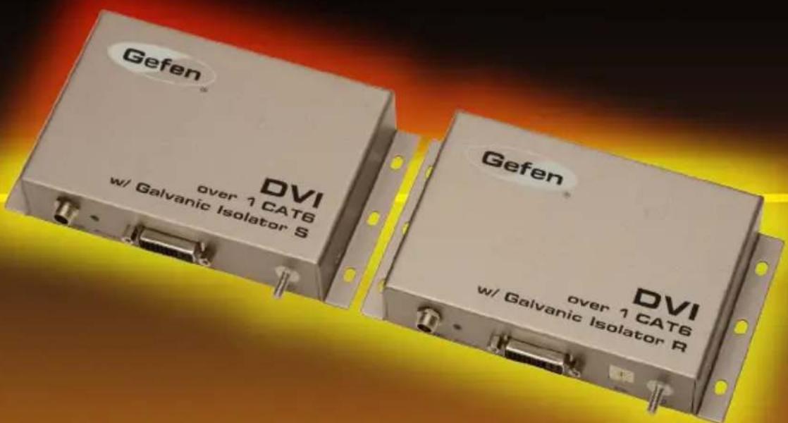
The DVI over 1 CAT6 /w Galvanic Isolator ships with the items listed below. If any of these items are not present in the box when you first open it, immediately contact your dealer or Gefen.
• 1 x DVI over 1 CAT6 w/ Galvanic Isolator (Sender unit)
- 1 x DVI over 1 CAT6 w/ Galvanic Isolator (Receiver unit)
- 1 x 6 ft. Dual Link DVI cable
- 2 x 5V DC Power Supplies
• 1 x Quick-Start Guide
1 Getting Started
Introduction....2
Sender unit....2
Receiver unit 4
Installation....6
Connection Instructions....6
Sample Wiring Diagram 6
2 Basic Operation
DIP Switch Configuration 10
Default Settings.... 10
EDID Management.... 11
Color Management.... 11
Adjusting the Signal Quality 12
3 Appendix
Surface Mounting Instructions.... 16
Specifications 17
DVI over 1 CAT6
w/ Galvanic Isolator
1 Getting Started
Introduction....2
Sender unit....2
Receiver unit 4
Installation 6
Connection Instructions....6
Sample Wiring Diagram 6
Sender unit
Gefen
DVI
over 1 CAT6
w/ Galvanic Isolator S
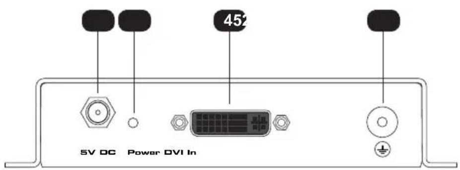
| ID Name Description | ||
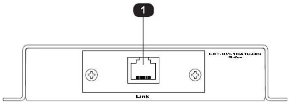
| 1 Link Connect a CAT-5e cable (or better) from this port to the Link port on the Receiver unit. | ||
| 2 5V DC Connect the included 5V DC power supply to this power receptacle. | ||
| 3 Power This LED will glow bright blue once the included 5V DC power supply has been properly connected between the locking power receptacle and an available electrical outlet. | ||
| 4 DVI In Connect the included DVI cable between the imaging source (e.g. imaging camera) and the DVI In port. | ||
| 5 Grounding Terminal Connect a grounding wire from this terminal to an approved Earth ground. The grounding wire should not be less than 16 AWG. |
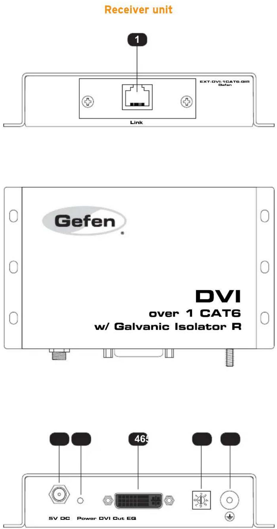
| ID Name Description | ||
| 1 Link Connect a CAT-5e cable (or better) from this port to the Link port on the Sender unit. | ||
| 2 5V DC Connect the included 5V DC power supply to this power receptacle. | ||
| 3 Power This LED will glow bright blue once the included 5V DC power supply has been properly connected between the locking power receptacle and an available electrical outlet. | ||
| 4 DVI Out Connect a DVI cable between the imaging system (display) and the DVI Out port. | ||
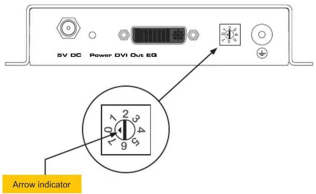
| 5 EQ Use this EQ pot to optimize the output signal based on extension distance and cable skew. See Adjusting the Signal Quality (page 12) for more information. | ||
| 6 Grounding Terminal Connect a grounding wire from this terminal to an approved Earth ground. The grounding wire should not be less than 16 AWG. |
Connection Instructions
- Connect the included DVI cable from the imaging source (e.g. camera) to the DVI In port on the Sender unit.
- Connect a DVI cable from the DVI Out port, on the Receiver unit, to a video scaler or high-resolution imaging display.
- Connect a single CAT-5e or better cable from the Link jack on the Sender unit to the Link jack on the Receiver unit.
- Connect a ground wire from the grounding terminals, on both the Sender and Receiver unit, to an approved Earth ground. The ground wire should not be less than 16 AWG.
- Use the included locking power supplies to connect the Sender and Receiver unit to available electrical outlets. Do not overtighten the locking power connectors.

Important!
The grounding terminal must be permanently connected to an approved Earth ground by wiring not less than 16 AWG.
Sample Wiring Diagram

Galvanically Isolated
CAT-5e or CAT-6A CABLE
DVI CABLE



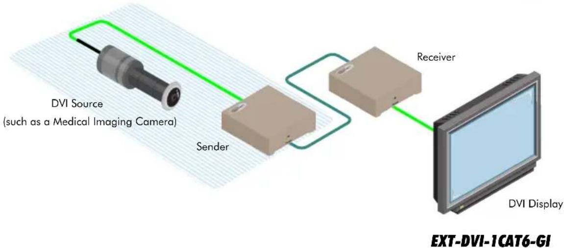
flowchart
graph LR
    A["DVI Source (such as a Medical Imaging Camera)"] --> B["Sender"]
    B --> C["Receiver"]
    C --> D["DVI Display"]
DVI over 1 CAT6
w/ Galvanic Isolator
2 Basic Operation
DIP Switch Configuration .... 10
Default Settings....10
EDID Management....11
Color Management....11
Adjusting the Signal Quality 12
On the bottom panel of the Sender unit is a bank of 4 DIP switches. Remove the piece of colored tape to reveal the DIP switch bank. These DIP switches provide control over EDID management and color depth. DIP switches 3 and 4 are not used.
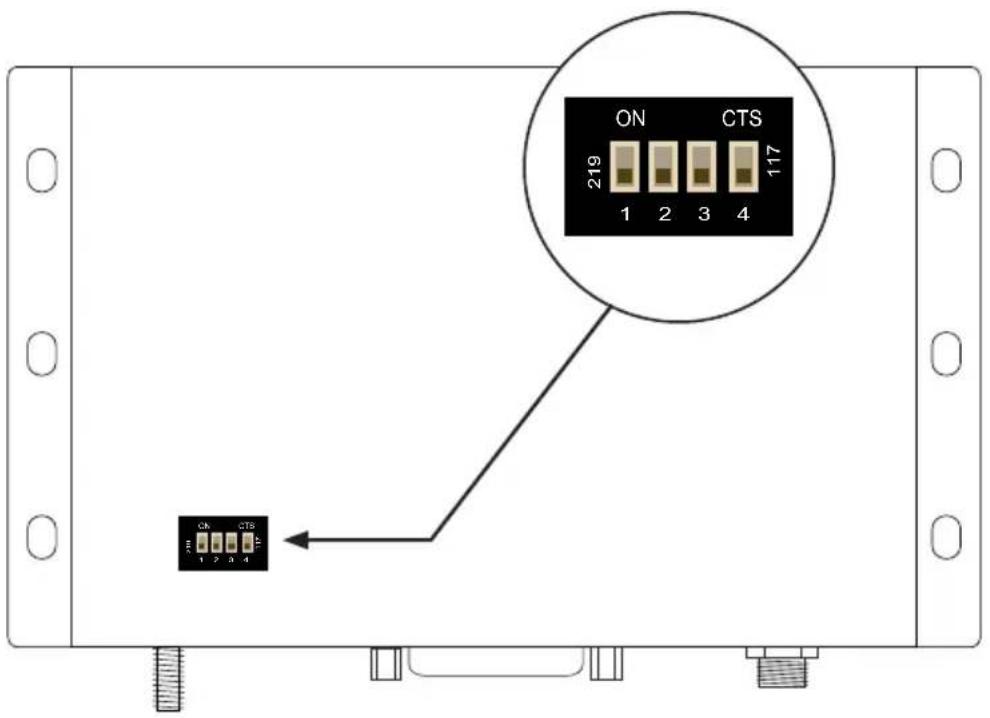
Default Settings
The following table lists the default (factory) settings of each DIP switch. See the following page for details on each DIP switch function.
| DIP Switch Description | ||
| 1 | ONUses pass-through (downstream) EDID mode | 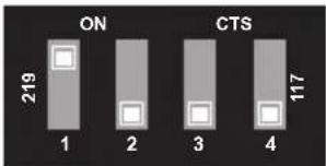 |
| 2 OFF | Deep color is disabled. | |
EDID Management
The DVI over 1 CAT6 w/ Galvanic Isolator can be switched between two EDID modes: Internal or Pass-through. After changing DIP switch 1, the Sender unit must be power-cycled for changes to take effect.
| DIP Switch 1 Description | ||
| ON (default) | Pass-through mode. DDC and HPD are passed through. Both the connection status and the full video capabilities of the monitor are passed to the source device. | 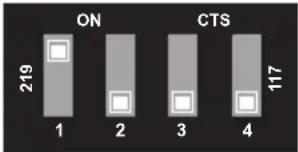 |
| OFF Internal EDID mode. In this mode, a generic EDID will be sent to the source device. This setting is useful when sufficient EDID data is unavailable from the display device or EDID-related problems are encountered. | 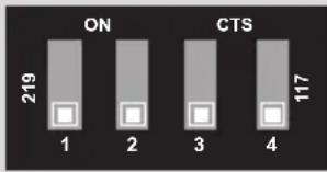 | |
Color Management
This feature is used to control the color depth for resolutions up to 1080i. By default, the color depth is set to 8-bit. If the output resolution is 1080p or if DIP switch 1 is ON, then this DIP switch setting has no effect.
| DIP Switch 2 Description | ||
| OFF (default) | Disables Deep Color support on the output (display) device. | 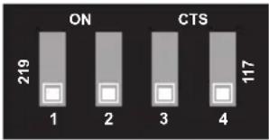 |
| ON Enables Deep Color (12-bit) support on the output (display) device. | 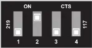 | |
Adjusting the Signal Quality
The Receiver unit of the DVI over 1 CAT6 w/ Galvanic Isolator has a trim pot that is used to equalize the output signal, compensating for extension distance and cable skew. If there is no output video or if output video contains video artifacts and/or video noise such as snow, use the steps below to adjust the trim pot.
- Use a small flat-headed tool to turn the EQ pot.
- The trim pot has eight different positions (0 through 7). Turn the trim pot in a clockwise direction until it clicks to the next position. The arrow indicator on the trim pot will indicate the current position.
- Check the image.
- If necessary, continue adjusting the rotary switch until the issue is resolved.

Information
Any time a cable is replaced, the EQ trim pot on the Receiver unit will need to be adjusted.
DVI over 1 CAT6
w/ Galvanic Isolator
3 Appendix
Surface Mounting Instructions.... 16
Specifications 17
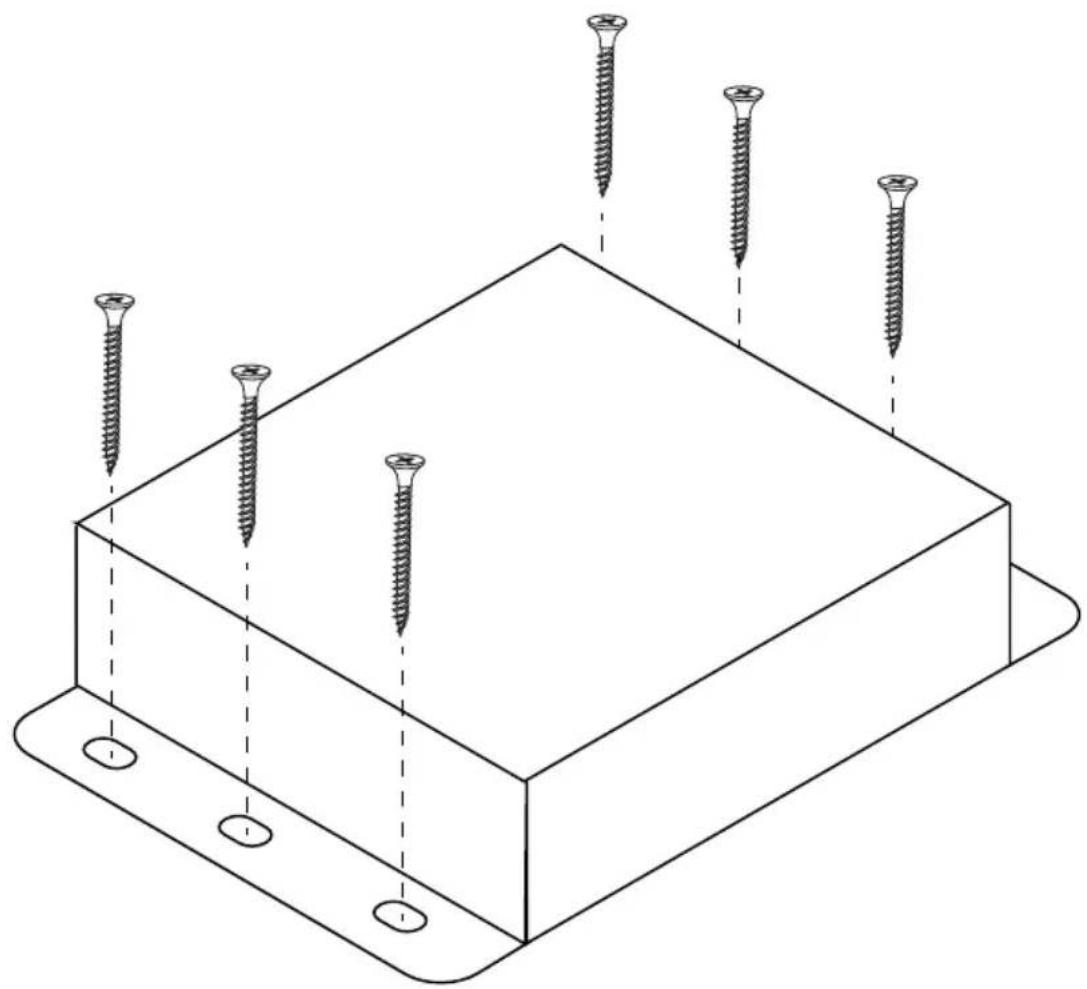
The Sender and Receiver units can be mounted on any flat surface, as shown below (screws not included). There should be an inch or two of clearance between the edges of the unit and any walls or vertical surfaces to allow for enough clearance for connection and disconnection of the DVI cables.
For installation on a drywall surface, use a #6 drywall screw. When installing, it is recommended to use the center hole on a stud.
natural_image
Isometric line drawing of a rectangular plate with six screws inserted, no text or symbols presentConnectors & Indicators
| Video Input (Sender) • 1 x DVI 29-pin, female (digital only) |
| Video Output (Receiver) • 1 x DVI 29-pin, female (digital only) |
| Link (Sender / Receiver) • 1 x RJ-45 |
| Power (Sender / Receiver) • 1 x Locking-type |
| Power Indicator (Sender / Receiver) • 1 x LED, blue |
| EDID Selector (Sender) • 1 x DIP switch |
| Deep Color Selector (Sender) • 1 x DIP switch |
| EQ Adjustment (Receiver) • 1 x 8-position rotary switch |
Operational
| Maximum Pixel Clock • 165 MHz | |
| Power Input • 5V DC | |
| Power Consumption (Sender / Receiver) | • 4 Watts (ea.) (max.) |
| Storage Temperature • -4 °F ~ +158 °F | (-20 °C ~ +70 °C) |
| Relative Humidity • Environmental | 10% to 90% (non-condensing) |
| • Operating 10% to 80% (non-condensing) | |
| Atmospheric Pressure • Environmental | 7.25 lbf/in ^2 to 15.4 lbf/in ^2 (50 kPa to 106 kPa) |
| • Operating 11 lbf/in ^2 to 15.4 lbf/in ^2 (76 kPa to 106 kPa) | |
| Operating Temperature | • +41 to +104 °F (+5 to +40 °C) |
| MTBF | • 50000 Hours |
Physical
| Dimensions (W x H x D)(Sender / Receiver) | • 5.6" x 1.1" x 3.4" (143mm x 28mm x 86mm) |
| Unit Weight (each) | • 0.4 lb (0.18 kg) |

GEFEN
20600 Nordhoff St., Chatsworth CA 91311
1-800-545-6900 818-772-9100 fax: 818-772-9120
www.gefen.com support@gefen.com
- w/ Galvanic Isolator
- Technical Support
- Fax
- Web
- Mailing Address
- Product Registration
- Features
- HDCP COMPLIANT
- Packing List
- Getting Started
- Basic Operation
- Appendix
- DVI over 1 CAT6
- Gefen
- DVI
- Connection Instructions
- Important!
- Sample Wiring Diagram
- Default Settings
- EDID Management
- Color Management
- Adjusting the Signal Quality
- Information
Brand : Gefen
Model : EXT-DVI-1CAT6-GI
Category : Audio/video extension