
Fusion Remote Max - Desktop Computer ANTEC - Free user manual and instructions
Find the device manual for free Fusion Remote Max ANTEC in PDF.


| Product Type | Desktop Computer Case (Media Center / HTPC) |
| Model | Fusion Remote Max |
| Brand | Antec |
| Dimensions (W x D x H) | 440 x 430 x 140 mm |
| Weight | Approximately 6.5 kg |
| Form Factor Support | Mini-ITX, Micro-ATX, ATX |
| Power Supply Support | Standard ATX PS2 (not included) |
| Drive Bays | 2 x 5.25", 1 x 3.5" external, 3 x 3.5" internal, 2 x 2.5" internal |
| Cooling Options | Front 120mm fan (included), rear 92mm fan (optional) |
| Front Panel Ports | 2 x USB 3.0, 1 x USB 2.0, Audio In/Out |
| Remote Control | Infrared remote included for media center control |
| Material | Steel chassis with brushed aluminum front bezel |
| Expansion Slots | 7 |
| Maximum GPU Length | Up to 290 mm |
| Maximum CPU Cooler Height | Up to 145 mm |
| Cleaning and Maintenance | Wipe with a soft, dry cloth. Do not use liquids or abrasive cleaners. |
| Safety Precautions | Ensure proper ventilation; keep away from heat sources and liquids. |
| Spare Parts and Repairability | Contact Antec support for replacement parts. Standard components are user-replaceable. |
| General Information | Desktop computer case designed for home theater and media center use. |
Frequently Asked Questions - Fusion Remote Max ANTEC
User questions about Fusion Remote Max ANTEC
0 question about this device. Answer the ones you know or ask your own.
Ask a new question about this device
Download the instructions for your Desktop Computer in PDF format for free! Find your manual Fusion Remote Max - ANTEC and take your electronic device back in hand. On this page are published all the documents necessary for the use of your device. Fusion Remote Max by ANTEC.
USER MANUAL Fusion Remote Max ANTEC
Fusion Remote Max User's Manual
Manuel de l'utilisateur Anwenderhandbuch Manuale per l'operatore Manual del usuario
取扱説明書 中文使用手冊
At Antec, we continually refine and improve our products to ensure the highest quality. As such, it's possible that your new case may differ slightly from the description in this manual. This isn't a problem; it's simply an improvement. As of the date of publication, all features, descriptions, and illustrations in this manual are correct.
Disclaimer
This manual is intended only as a guide for Antec's Computer Enclosures. For more comprehensive instructions on installing the motherboard and peripherals, please refer to the user's manuals that come with those components.
Fusion Remote Max User's Manual
Fusion Remote Max – Media Center Case
The Fusion Remote Max comes without a power supply. Make sure you choose a power supply that is compatible with your computer components and has a long enough power harness to reach your motherboard and peripheral devices.
We recommend our TruePower Quattro, TruePower Trio, or NeoPower power supplies for the latest ATX specification compliance, broad compatibility, and power savings capability.
Although care has been taken to prevent sharp edges in your Antec case, we strongly recommend taking the appropriate time and care when working with it. Avoid hurried or careless motions. Please use reasonable precaution.
Setting Up
- Place the case upright on a flat, stable surface.
- Remove the thumbscrew from the back of the top panel. Slide the panel towards the rear to remove it from the case.
- Inside the case you should see some wiring with marked connectors (USB, PWR etc.), an installed I/O panel and a toolbox containing all the screws you need to install the components.
The Triple Chamber structure
Upon opening the top panel, you will find that the case is divided into three chambers: the power supply (PSU) chamber, the motherboard chamber and the HDD chamber. This triple chamber structure isolates the heat and noise within each chamber, resulting in much quieter and cooler operation than a traditional desktop case design.
In the motherboard chamber, a 140mm TriCool fan is installed on the side of the case and a 120mm TriCool ™ rear fan is installed at the rear of the case right next to the CPU for effective CPU cooling.
In the PSU chamber, there is room for two hard drives. The HDD chamber can hold 2 more hard drives.
Installing the Motherboard
This manual does not cover CPU, RAM, or expansion card installation.
Please consult your motherboard manual for specific mounting instructions and troubleshooting.
- Lay the case down, with the top open.
- Make sure you have the correct I/O panel for your motherboard. If the panel provided with the case isn't suitable, please contact your motherboard manufacturer for the correct I/O panel.
- Line up your motherboard with the standoff holes, and remember which holes are lined up. Not all motherboards will match with all the provided holes; this is normal and won't affect functionality.
- Remove your motherboard by lifting it up.
- Screw the brass standoffs into the threaded holes that line up with your motherboard. Do not over-tighten the standoffs. Some standoffs may be pre-installed for your convenience.
- Place your motherboard on the brass standoffs.
- Secure your motherboard to the standoffs with the provided Philips-head screws. Your motherboard is now installed.
Connecting the Switches and LED
- Connect the Reset switch (labeled RESET SW) to the motherboard at the RST connector. Polarity (positive and negative) does not matter for switches.
- Connect the Power Switch (labeled POWER SW) from the front LCD display to the PWR connector on the motherboard.
Note: The Power Switch from the front I/O is connected to the LCD display module by default. This will allow you to turn your system on and off using the remote control. If you choose to connect the Power Switch from the front I/O directly to the motherboard instead of via the LCD display, you won't be able to control system power using the remote control. - The Power LED (labeled POWER LED) connector is located behind the Reset connector. For LEDs, colored wires are positive (+). White or black wires are negative (−). If the LED does not light up when the system is powered on, try reversing the connection. For more info on connecting LEDs to your motherboard, see your motherboard manual.
- The Hard Drive LED (labeled HDD LED) connects to the hard drive activity header on your motherboard or RAID card.
Installing the Power Supply
- Orient the power supply vertically, and set it on the three rubber pads at the bottom of the PSU chamber.
Note: Power supplies with fans on the bottom of the power supply will need to be mounted so that the fan is facing the side ventilation port. The power supply mounting holes on your Fusion Remote Max case allow the PSU to be installed in either orientation. - Push the power supply to the back of the case and align the mounting holes.
- Secure the power supply to the case with the screws provided.
- Loosen the screw on the sliding black plate and widen the opening so you can feed the necessary power cables through to the other side.
- Slide the plate back to constrict the opening and secure it with the screw, so that the airflow in the case works as designed.
Connecting the USB Ports
You will find a single 10-pin connector on a cable attached to the front USB ports. This is an Intel® standard connector that is keyed so that it can't be accidentally reversed when connected to a proper Intel® standard motherboard header. Connect
the 10-pin connector to the motherboard headers so that the blocked pin fits over the missing header pin.
Note: Please check the motherboard manual for the USB header pin layout and make sure it matches the following table.
Motherboard USB Pin Layout

| Pin Signal Names Pin Signal Names | |||
| 1 | USB Power 1 | 2 | USB Power 2 |
| 3 | Negative Signal 1 | 4 | Negative Signal 2 |
| 5 | Positive Signal 1 | 6 | Positive Signal 2 |
| 7 | Ground 1 | 8 | Ground 2 |
| 9 | Key (No Connection) | 10 | Empty Pin |
Connecting the IEEE 1394 (FireWire®, i.Link®) Port
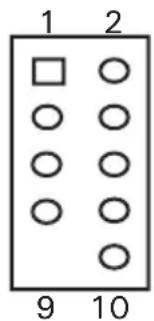
You will find a single 10-pin connector on a cable attached to the front IEEE 1394 connection. This is an Intel® standard connector that is keyed so that it can't be accidentally reversed when connected to a proper Intel® standard motherboard header. Connect the 10-pin connector to the motherboard header so that the blocked pin fits over the missing header pin.
Note: Please check the motherboard manual for your IEEE 1394 header pin layout and make sure it matches the table below. If you intend to connect the front FireWire port to an IEEE 1394 add-on card that comes with an external-type IEEE 1394 connector, you will need a FireWire Internal Adapter. To order one, please visit Antec's web store at http://www.antec.com/StoreFront.bok and search for part number 30031. This adapter will allow you to connect the front IEEE 1394 port to the external-type connector.
Pin Assignment for Front Panel IEEE 1394 Connector
| Pin Signal Names Pin Signal Names | |
| 1 TPA + 2 TPA- | |
| 3 Ground 4 Ground | |
| 5 TPB + 6 TPB- | |
| 7 + 12V (Fused) 8 + 12V (Fused) | |
| 9 Key (No Pin) 10 Ground |
Connecting the eSATA Port
You will find a SATA connector on a cable attached to the front ports. This is an internal SATA connector, which is designed to connect to a standard SATA connector on your motherboard.
Connecting the Audio Ports (AC'97 and HDA)
There is an Intel ® standard 10-pin AC'97 connector and an Intel ® 10-pin HDA (High Definition Audio) connector, either of which can be connected to your motherboard depending on the specification of the motherboard.

| Pin Signal Names (HDA) | Pin Signal Names (AC'97) |
| 1 MIC 2 L 1 MIC In | |
| 2 AGND 2 GND | |
| 3 MIC 2 R 3 MIC Power | |
| 4 AVCC 4 NC | |
| 5 FRO-R 5 Line Out (R) | |
| 6 MIC 2_JD 6 Line Out (R) | |
| 7 F_IO_SEN 7 NC | |
| 8 Key (no pin) 8 Key (no pin) | |
| 9 FRO-L 9 Line Out (L) | |
| 10 LINE2_JD 10 | Line Out (L) |
Locate the internal audio connectors from your motherboard or sound card.
Consult your motherboard or sound card manual for the pin-out positions.
The Display/Volume Control and the Remote Control
Fusion Remote Max comes with a Liquid Crystal Display (LCD) Display. It has a built-in MCE-compatible IR receiver, and a volume control to work with your media center computer. It also comes with a remote control to work with Windows® MCE.and iMEDIAN HD software.
- Make sure the power supply is off and unplugged before installing any hardware.
- There is a 24-pin power adapter comes with the case. Connect the adapter to the power supply 24-pin ATX power connector. Connect the 3-pin power cable from the display to the 3-pin connector on the 24-pin adapter.
- The display comes with a 4-pin internal USB adapter (see picture 1) and a standard external USB connector.
To connect the display, either:
a. Connect the external connector to a standard USB port, or
b. Check your motherboard USB header pin layout.
Match the internal adapter to
your motherboard header. Plug the internal adapter into the external connector and plug it in to your motherboard's USB header.

Picture 1
- Plug in your power supply and turn it on.
- Boot your computer.
- Insert the provided driver CD into your optical drive and install the included software.
- Restart after the driver has been installed.
- Software use and capabilities
a. Press the "go" button to launch iMEDIAN HD
b. See the diagram at the back of the manual for descriptions of the functions of the keys on the remote control.
c. Navigating iMEDIAN HD
Use the 4-way buttons to navigate iMEDIAN HD. Holding the left and right buttons will take you to the "Home" and "Menu" screens
d. Local Media
Users can easily enjoy music, videos, and pictures on their PC by using just the remote control. IMEDIAN HD supports every essential internal codec.
e. Network Media
Users can easily enjoy media files on other local PCs as well as Internet radio.
f. CD/DVD
Users can listen to CDs or watch DVDs
g. TV
Users can watch and record digital/analog TV channels by TV card on the PC.
h. Tasks
Users can check RSS news feeds, world city time and weather, manage their files, set an alarm, and shut down their system
i. Settings
Users can change and adjust settings such as GUI, Media Playback features, and more
Hard disk Drive Installation
Besides the motherboard chamber, there are the HDD chamber and the Power Supply Chamber. Each chamber comes with a hard disk drive bracket with soft silicone grommets. Each can hold two hard drives.
- Remove the HDD bracket from the chamber by removing the four screws on top of it.
- Mount your hard drive onto the drive bracket through the top silicone grommets with the special screws provided. Make sure to install the HDD with the cable side facing the arrow mark on the bracket. (see picture 2)
Note: Do not over-tighten the screws, as this will reduce the vibration and noise-dampening ability of the silicone grommets. Always mount the HDD with the thicker side of the silicone grommets facing up.

Picture 2
- Drop the HDD/bracket assembly back into the case.
- Fasten the bracket using the screws provided.
- Connect 4-pin molex or SATA power connectors on the power supply to the power connectors on each of the devices.
5.25" Device Installation
This case comes with one 5.25" external drive bay right under the LCD.
- Remove the flip-up drive cage.
- Insert the 5.25" device into the lower 5.25" drive bay of the cage. Make sure to use the rear set of screw holes on the cage to mount the device. Fasten the drive with the screws included.
Note: The upper 5.25" drive bay is reserved for LCD. Do not mount any device into this bay.
- Find a 4-pin molex or SATA connector on the power supply and connect it to the power connector on the device.
The Cable Management
There is a cable management compartment under the 5.25" flip-up cage. Remove the cage to expose the compartment. Hide or route your excess cables to this compartment. Secure excess cables with the reusable cable ties as needed.
Cooling System
The Fusion Remote Max comes with a 120mm TriCool™ rear exhaust fan located in the motherboard chamber. This fan has a three-speed external switch at the back of the case that allows you choose between quiet, performance, or maximum cooling (Please see specifications below). Connect the 4-pin Molex connector from the fan to a 4-pin connector on the power supply.
120mm Fan Specifications:
Size: 120 x 120 x 25mm TriCool™ Fan
Rated Voltage: 12V DC
Operating Voltage: 10.2V \~ 13.8V
| Speed RPM | Input Current | Air Flow | Static Pressure | Acoustical Noise | Input Power |
| High 2000 | 0.24A (Max.) | 2.24 m3 / min (79 CFM) | 2.54 mm- H2O (0.10 inch- H2O ) | 30 dBA 2.9 W | |
| Medium 1600 | 0.2A | 1.59 m3 / min (56 CFM) | 1.53 mm- H2O (0.06 inch- H2O ) | 28 dBA 2.4 W | |
| Low 1200 | 0.13A | 1.1 m3 / min (39 CFM) | 0.92 mm- H2O (0.04 inch- H2O ) | 25 dBA 1.6 W |
The 140mm TriCool™ Fan
The Fusion Remote Max comes with a 140mm side exhaust fan. This fan has a three-speed external switch at the back of the case that allows you choose between quiet, performance, or maximum cooling (Please see specifications below). Connect the 4-pin Molex connector from the fan to a 4-pin connector on the power supply.
140mm TriCool Specifications:
Size: 140 x 140 x 25mm TriCool Fan
Rated Voltage: 12V DC
Operating Voltage: 10.2V \~ 13.8V
| Speed (RPM) | Input Current | Air Flow Static Pressure | Acoustical Noise | Input Power | |
| High 1500 | 0.28A (max.) | 2.68 m3 / min (94.6 CFM) | 1.685mm- H2O (0.066inch- H2O ) | 31.8 dBA 3 | 36 W |
| Medium 1100 | 0.20A | 1.89 m3 / min (66.8 CFM) | 0.934mm- H2O (0.036inch- H2O ) | 21.4 dBA 2 | 4 W |
| Low 700 | 0.15A | 1.33 m3 / min (47 CFM) | 0.40mm- H2O (0.015inch- H2O ) | 19.8 dBA 1 | 8 W |
Note: The minimum voltage to start the fan is 5V. We recommend our users to set the fan speed to High if you choose to connect the fan to a fan control device. A fan-controller regulates the fan speed by varying the voltage to it. The voltage may start as low as 4.5V to 5V. Connecting a TriCool™ fan set on Medium or Low to a fan-control device may result in the fan not being able to start.
The Optional 120mm Fan for Graphic Cards
The Fusion Remote Max comes with a 120mm fan bracket with built-in full length PCI cardholder. Remove the HDD bracket and the metal piece separating the HDD chamber as shown. Install a 120mm fan into the bracket and install the fan assembly to the case as shown. This fan will blow the air across the graphic cards. (see picture 3)

Picture 3
The Bottom Air Intake
There are intake vents at the bottom of the case right under the HDD chamber and power supply chamber. Cool air will flow into the vents around the hard drives, and then flow into the motherboard chamber and exhaust by the 120mm and 140mm TriCool™ fans.
Note: Do not place the Fusion Remote Max on a soft surface or over anything that will block the bottom air vents.
The Upper Air Intake
There are vents on the top panel above the PCI expansion slot. Cool air will flow through it into the motherboard chamber to cool the VGA card.
Note: Do not place anything on top of the Fusion Remote Max that will block the top air vents.
The Rear Air Intake
There are vents right above the rear I/O panel and on the PCI expansion slot covers to bring in cool air to the CPU and VGA card.
The Air Guide
There is an air guide right between the rear 120mm fan and the rear air intake vents. This is an important part of the ventilation design of this case. Adjust the Air Guide by adding or removing stacking sections to best suit the location of your CPU on the motherboard. This will force the cool external air that is coming in through the rear intakes to be directed to the graphic cards and CPU to enhance cooling of those components.
The Power Supply Air Intake
Power supplies with 120mm fans or larger can get air directly from outside of the case through vents on the left side.
Note: Please leave at least 1" (2.5cm) between the left side of the case and anything that could block airflow to the power supply. This is required in order for the power supply to have sufficient cooling. For users who choose the use a power supply with an 80mm fan, fresh air will come from the bottom air intake.
The Washable Air filters
There are two filters located behind the front bezel door.
- Flip down the front bezel door.
- Push to release one of the filters from its holding position
- Wash the filter with water.
- Insert the filter back to its original position until it clicks.
From time to time it will be necessary to wash the installed air filters. Not washing the air filter will result in higher system temperatures and possible stability problems. We recommend checking the air filter at least once a month initially. The frequency will change depending on system usage (users who run their systems 24/7 will likely have to check/wash more often than those who don't use their systems every day) and on environmental conditions.
RM200
- Application Exit: Close the active window or close iMEDIAN HD [ALT + F4]
- Power: Turn the PC on/off (Power switch also located on the internal receiver)
- Record
- Media Control Group 1: Play/Pause/Stop/Open/Prev/Next/Rew/F.Fwd
- Mouse/Keyboard: Switch the PAD controller between a mouse and a keyboard
-
Backspace: View previous menu
-
Select/Space
-
PAD Controller: Mouse cursor control & 4-way arrow keys
-
Windows Start
-
Windows Menu
- Mouse left click
-
Mouse right click
-
ENTER
-
Esc
-
Open/Close: Open or close DVD or CD-ROM tray
-
"go": Start iMEDIAN HD application
-
Application Launcher: Run an application
-
Task Switch: Switch between running applications [ALT-TAB]
-
Mute
-
Timer: Use a timer to manage on/off and alarm schedule
-
VOL/CH: Change the volume and TV channel
-
Custom button group for user-customized commands
-
Media Control Button Group 2

Antec, Inc.
47900 Fremont Blvd.
Fremont, CA 94538
USA
tel: 510-770-1200
fax: 510-770-1288
Antec Europe B.V.
Stuttgartstraat 12
3047 AS Rotterdam
The Netherlands
tel: +31 (0) 10 462-2060
fax: +31 (0) 10 437-1752
Customer Support:
US & Canada
1-800-22ANTEC
customersupport@antec.com
Europe
+31 (0) 10 462-2060
europe.techsupport@antec.com
www.antec.com



- FUSION REMOTE MAX USER'S MANUAL
- DISCLAIMER
- FUSION REMOTE MAX – MEDIA CENTER CASE
- SETTING UP
- THE TRIPLE CHAMBER STRUCTURE
- INSTALLING THE MOTHERBOARD
- CONNECTING THE SWITCHES AND LED
- INSTALLING THE POWER SUPPLY
- CONNECTING THE USB PORTS
- CONNECTING THE IEEE 1394 (FIREWIRE®, I.LINK®) PORT
- CONNECTING THE ESATA PORT
- CONNECTING THE AUDIO PORTS (AC'97 AND HDA)
- THE DISPLAY/VOLUME CONTROL AND THE REMOTE CONTROL
- HARD DISK DRIVE INSTALLATION
- 5.25" DEVICE INSTALLATION
- THE CABLE MANAGEMENT
- COOLING SYSTEM
- 120MM FAN SPECIFICATIONS
- THE 140MM TRICOOL™ FAN
- 140MM TRICOOL SPECIFICATIONS
- THE OPTIONAL 120MM FAN FOR GRAPHIC CARDS
- THE BOTTOM AIR INTAKE
- THE UPPER AIR INTAKE
- THE REAR AIR INTAKE
- THE AIR GUIDE
- THE POWER SUPPLY AIR INTAKE
- THE WASHABLE AIR FILTERS
- RM200
Brand : ANTEC
Model : Fusion Remote Max
Category : Desktop Computer