VPort 254 - Server Moxa - Free user manual and instructions
Find the device manual for free VPort 254 Moxa in PDF.


| Product Type | Industrial Video Server / Encoder |
| Dimensions | 100 x 80 x 30 mm (approx.) |
| Weight | 0.5 kg (approx.) |
| Power Supply | 12V DC or PoE (Power over Ethernet) |
| Video Compression | H.264, MJPEG |
| Video Input | 1x BNC composite video |
| Ethernet Port | 1x RJ45 10/100 Mbps |
| Serial Port | 1x RS-232/422/485 |
| Operating Temperature | -40°C to 75°C (industrial grade) |
| Main Functions | Real-time video encoding, IP streaming, motion detection, alarm input |
| Management | Web-based interface, SNMP, Moxa VPort SDK |
| Storage | SD card slot for local recording |
| Mounting | DIN-rail or wall-mount |
| Operating System | Embedded Linux |
| Security | Password protection, IP filtering, HTTPS |
| Maintenance & Cleaning | Use a dry soft cloth to clean the device; avoid liquids. |
| Spare Parts & Repairability | Contact Moxa support for replacement parts; device is not user-serviceable. |
Frequently Asked Questions - VPort 254 Moxa
User questions about VPort 254 Moxa
0 question about this device. Answer the ones you know or ask your own.
Ask a new question about this device
Download the instructions for your Server in PDF format for free! Find your manual VPort 254 - Moxa and take your electronic device back in hand. On this page are published all the documents necessary for the use of your device. VPort 254 by Moxa.
USER MANUAL VPort 254 Moxa
Moxa VPort 254 Industrial Video Encoder
User's Manual
First Edition, November 2008
MOXA®
© 2008 Moxa Inc. All rights reserved. Reproduction without permission is prohibited.
Moxa VPort 254 Industrial Video Encoder User's Manual
The software described in this manual is furnished under a license agreement and may be used only in accordance with the terms of that agreement.
Copyright Notice
Copyright © 2008 Moxa Inc.
All rights reserved.
Reproduction without permission is prohibited.
Trademarks
MOXA is a registered trademark of the Moxa Inc.
All other trademarks or registered marks in this manual belong to their respective manufacturers.
Disclaimer
Information in this document is subject to change without notice and does not represent a commitment on the part of Moxa.
Moxa provides this document “as is,” without warranty of any kind, either expressed or implied, including, but not limited to, its particular purpose. Moxa reserves the right to make improvements and/or changes to this manual, or to the products and/or the programs described in this manual, at any time.
Information provided in this manual is intended to be accurate and reliable. However, Moxa assumes no responsibility for its use, or for any infringements on the rights of third parties that may result from its use.
This product might include unintentional technical or typographical errors. Changes are periodically made to the information herein to correct such errors, and these changes are incorporated into new editions of the publication.
Technical Support Contact Information
www.moxa.com/support
Moxa Americas:
Toll-free: 1-888-669-2872
Tel: +1-714-528-6777
Fax: +1-714-528-6778
Moxa China (Shanghai office):
Toll-free: 800-820-5036
Tel: +86-21-5258-9955
Fax: +86-10-6872-3958
Moxa Europe:
Tel: +49-89-3 70 03 99-0
Fax: +49-89-3 70 03 99-99
Moxa Asia-Pacific:
Before getting started
Before using your VPort 254, please pay close attention to the following instructions:
☐ After opening the VPort 254 box, compare the contents of the box with the Package Checklist in Chapter 1. Notify your sales representative if any of the items is missing or damaged.
☐ To prevent damage or problems caused by improper usage, before assembling and operating the device and peripherals, read the Quick Installation Guide (the printed handbook included in the package). You may also refer to Chapter 1, under Product Description, and all of Chapter 2, of this manual.
☐ If you experience a system error, and the system does not recover easily, refer to the Troubleshooting section in Chapter 7 to learn how to restore factory default settings and reinstall the system.
☐ The VPort 254 Video encoder has been designed for various environments and can be used to build various applications for general security or demonstration purposes. For standard applications, refer Chapter 2, Getting Started, and Chapter 3, Accessing VPort 254 Video Encoder for the First Time.
Important Note
☐ Surveillance devices may be prohibited by law in your country. Since VPort is both a high performance surveillance system and networked video server, ensure that the operations of such devices are legal in your locality before installing this unit for surveillance purposes.
Table of Contents
Chapter 1 Introduction....1-1
Overview....1-2
Package Checklist....1-4
Product Features 1-4
Typical Application.... 1-5
Panel Layout of the VPort 254....1-6
Product Description 1-7
Chapter 2 Getting Started....2-1
Before Getting Started 2-2
Initial Installation and Configuration....2-2
RS-232 Console Configuration (115200, None, 8, 1, VT1 00) 2-10
Mounting the VPort 254 Dimension 2-14
DIN-Rail Mounting 2-15
Wall Mounting....2-15
Wiring Requirements 2-16
Grounding the VPort 254.... 2-17
Wiring the Redundant Power Inputs.... 2-17
Wiring the Relay Output.... 2-18
Wiring the Digital Inputs 2-18
RS-232 Connection.... 2-19
10/100BaseT(X) Ethernet Port Connection 2-20
100BaseFX Ethernet Port Connection 2-21
COM port....2-21
PTZ Port 2-22
Chapter 3 Accessing VPort 254's Web-based Manager....3-1
Functions Featured on the VPort's Web Homepage.... 3-2
VPort's Information....3-2
Server Name 3-2
Camera Image View 3-3
Audio Control 3-3
Client Setting 3-3
System Configuration 3-4
Video Information 3-4
PTZ Control Panel 3-5
PTZ (Motorized) Camera Control 3-5
Custom PTZ Camera Commands 3-6
Video Image Snapshots 3-6
Relay Control....3-6
Chapter 4 System Configuration....4-1
System Configuration by Web Console 4-2
System 4-3
Network 4-10
Video 4-25
Serial Port 4-32
Audio 4-41
Alarm 4-41
Appendix A Frequently Asked Questions ...... A-1
Appendix B Settings of Supported PTZ Cameras......B-1
Appendix C Time Zone Table......C-1
Appendix D Technical Specifications ...... D-1
The VPort 254 is a rugged networking video encoder designed for use in harsh environments. In addition to being able to handle basic video feeds, many advanced features are also included to set up surveillance or web attraction applications. The VPort 254 is designed to provide stability, robustness, ease-of-use, and flexibility.
The following topics are covered in this chapter:
Overview
Package Checklist
□ Product Features
□ Typical Application
☐ Panel Layout of the VPort
□ Product Description
Overview
The VPort 254 is a 4-channel industrial video encoder that uses the ASIC compression chip to provide video performance up to full D1 (720 x 480) @ 30 FPS and CIF (352 x 240) @ 120 FPS for a total of 4 channels. To meet the wide range of requirements from end-users, the VPort 254 is designed to support dual-codecs, including MJPEG and MPEG4 algorithms.
The VPort 254 inherits the VPort 351's industrial features, but also supports DIN-Rail mounting, 12/24 VDC and 24 VAC redundant power inputs, -40 to 75°C operating temperature (“T” models only), and IP30 protection for industrial mission-critical applications. But most importantly, the VPort 254 meets critical hardware requirements for industrial safety and ruggedness, such as UL508, which is pertinent to TA, UA, and MA systems.
High Performance MJPEG/MPEG4 compression
Video input can be efficiently compressed into MJPEG/MPEG4 video stream packets without delay. This is all done without sacrificing remote monitoring capability or storage. Five levels of compression quality and four different image resolutions are provided to provide greater versatility.
2-way audio supported for a complete surveillance solution
The VPort 254 supports both audio input and audio output for voice over IP communication between a field site and central site. The 2-way audio function not only saves time, but also saves the cost of needing to add additional communication devices (such as a phone).
Rugged design for industrial environments
The VPort 254 is an industrial video encoder, which means that it is specially designed for harsh industrial environments. With the 12/24 VDC and 24 VAC redundant power inputs, IP30 protection, and DIN-Rail mounting, the VPort 254 meets the critical requirements of most industrial applications. Most importantly, the VPort 254-T can operate reliably in a -40 to 75°C temperature range, making it the first video encoder of its kind that can be used for extended temperature, industrial-grade applications. The VPort 254-T is an optimal solution for outdoor environments. In addition, the VPort 254 has received important industrial and safety approvals, such as UL508, making the VPort 254 well suited for transportation, utility, and manufacturing systems.
Modbus/TCP supported for convenient communication with SCADA/HMI
Most automation applications use SCADA/HMI systems to monitor and control field site devices and equipment. Many SCADA/HMI systems now require real-time video for remote monitoring, and for this reason, the VPort 254 supports the Modbus/TCP protocols, which enable direct communication between the VPort and the SCADA/HMI system, allowing administrators to determine the status of VPorts easily for maintenance purposes.
Supports serial-to-Ethernet communication for connecting a serial device
In addition to video cameras, surveillance systems also use other devices, such as sensors and card readers. To reduce the connection effort and the cost of devices, the VPort 254 provides one serial-to-Ethernet RS-232/422/485 COM port for connecting serial devices.
RTSP streaming for easy integration
RTSP (Real-time Streaming Protocol) is a client-server multimedia presentation control protocol, which enables the interoperability of video devices and software. Hardware or software that supports RTSP streaming can easily identify and decode the video stream without the hassle of codec installation. For example, users can view video images from the VPort 254 directly with Quick Time and VLC, both of which support RTSP streaming.
Multicast (IGMP) transmission for network efficiency
Transmitting digital video images via an IP network requires a dozen times the bandwidth required for transmitting general data. For this reason, the efficiency of network bandwidth management is one of the most important issues that determines the performance of a video over IP surveillance system. The VPort 254 supports multicast transmission with IGMP protocol, which can reduce the bandwidth requirements when multiple clients access the same video stream, and greatly increases the efficiency of network bandwidth management.
Easy web access using standard browsers
There is no need to install new software to access the video encoder, since the embedded web server allows users to use any popular web browser to access the video encoder from anywhere over the Internet. As long as you are connected to the network, you will be able to view the same images seen by your cameras.
Built-in 3 area-selectable Video Motion Detection (VMD) (after V2.0 firmware)
External sensors are not required, since the video channel can be configured to detect motion in 3 areas, making it easy to set up a security system in either your office or the field. And the customizable settings allow you to tune the system for both object size and sensitivity, making the video encoder adaptable to different environments.
Weekly schedule for automated surveillance (after V2.0 firmware)
The user-defined time period will check security settings on a weekly basis, and send notifications or drive external devices, making the VPort 351 suitable for more versatile applications.
Flexible I/O control for external devices (after V2.0 firmware)
4 opto-isolated sensor inputs and 2 relay outputs are provided to control external devices, giving system integrators the option of turning an analog system into an advanced security system.
Moxa SoftDVR Lite IP Surveillance Software
To extend the video encoder's capabilities, Moxa SoftDVRTM Lite IP Surveillance Software, which supports a maximum of 4 cameras in quad, is included free of charge, allowing users to turn their PC into a digital video recorder. Scheduling or one-click recording saves important images on your local hard disk, and the reliable motion detection and instant warning features make you ready for any situation. A quick and easy to use search and playback function lets you easily find the image you're looking for, so that you can inspect the images more carefully, and also save the output to an AVI file.
SDK support for developers
The high-performance video encoder can be integrated into many applications—without busting your budget—and the complete programming interface of the Moxa VPort SDK PLUS makes the developer's job easy and straightforward. To ask about SDK requirements, please contact a Moxa sales representative for details and an application form.
Package Checklist
The Moxa VPort 254 is shipped with the following items. If any of these items are missing or damaged, please contact your customer service representative for assistance.
- VPort 254
• 10-pin terminal block for 1 power input and 4 digital inputs - 8-pin terminal block for the other power input and 2 relay outputs
- 5-pin terminal block for RS-232/422/485 PTZ control port
- Quick Installation Guide
- Document & Software CD (includes User's Manual, Quick Installation Guide, Moxa IVN Solution Datasheet, and Utility)
- Warranty statement
NOTE: Notify your sales representative if any of the above items is missing or damaged.
Product Features
High Performance Video/Audio Networking Solution
- Works with NTSC/PAL analog video cameras
• Supports MPEG4/MJPEG video compression technologies
• 4 BNC video inputs
• Video stream up to 120 frames/sec in CIF (352 x 240) resolution through a total of 4 channels - Selection from full D1, 4CIF, VGA, CIF, and QVGA resolutions
• 1 audio input and 1 audio output for 2-way voice communication - TCP, UDP, and HTTP network transmission modes
• Supports Modbus/TCP for easy communication with SCADA systems
• Standard RTSP (Real-time streaming protocol) for easy integration - Supports multicast (IGMP) protocols for efficient network transmission; DDNS, UPnP and IP filtering supported
• Supports QoS (TOS) for priority transmission
• Supports SNMP V1/V2c/V3 for network management
• Built-in web server and RS-232 console for remote access and configuration
• One auto-sensing 10/100BaseT(X) Ethernet port or 100BaseFX (SC connector) - Can handle up to 8 simultaneous video streams of output
- Set video quality to CBR (constant bit rate) or VBR (variable bit rate)
- Supports 1 RS-232/422/485 DB9 COM port for controlling a PTZ (PAN/TILT/ZOOM) motorized camera or serial device via a TCP/IP network
- Supports 1 RS-232/RS-422/RS-485 5-pin PTZ port for controlling a PTZ (PAN/TILT/ZOOM) motorized camera via a TCP/IP network
• UPnP and IP filtering supported
Rugged Industrial Design
- Two 12/24 VDC and 24 VAC redundant power inputs with LED indicators
- -40 to 75°C operating temperature for critical industrial environments (“-T” models)
- 35 mm DIN-Rail mounting or panel mounting installation (requires optional accessories)
• IP30 protection form factor
• CE, FCC, and UL508 approvals for industrial applications
Intelligent Alarm Trigger
• Built-in Video Motion Detection (VMD) (firmware version V2.0 and later)
- Equipped with 4 DIs and 2 relays (DO) for external sensors and alarms (firmware version V2.0 and later)
- Snapshot images provided for pre, trigger, and post alarm (firmware version V2.0 and later)
- Sequential snapshot images supported
- Messages with snapshot images can be sent via FTP or Email (firmware version V2.0 and later)
- HTTP Action setting for alarm messages sent by HTTP event server
- Configure alarm activation schedule
Video Management and Control
- Moxa SoftDVR™ Lite IP Surveillance Software for viewing and recording bundled free
- Free Moxa VPORT SDK PLUS supported with flexible interface and sample codes for customized applications or system integration
NOTE
If you are interested in Moxa's VPORT SDK PLUS, please go to Moxa's website www.moxa.com to download the package, or contact a Moxa sales representative for more information about this SDK
Typical Application
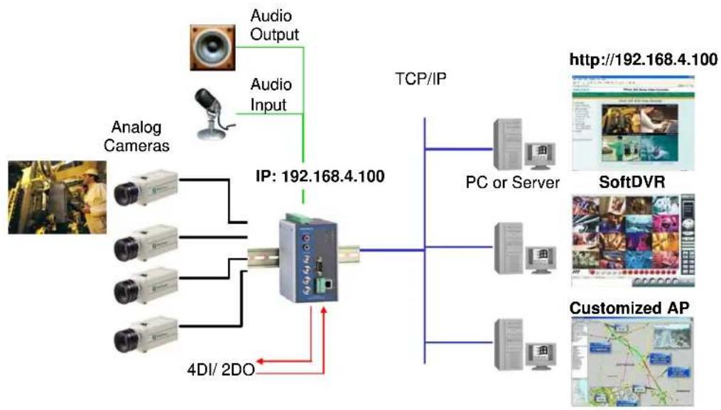
flowchart
graph TD
    A["Analog Cameras"] --> B["IP: 192.168.4.100"]
    C["Audio Input"] --> B
    D["Audio Output"] --> B
    B --> E["TCP/IP"]
    E --> F["PC or Server"]
    E --> G["SoftDVR"]
    E --> H["Customized AP"]
    B --> I["4DI/2DO"]
Panel Layout of the VPort 254
VPort 254
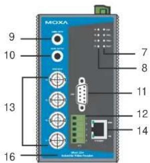
Front Panel View
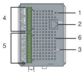
Top Panel View
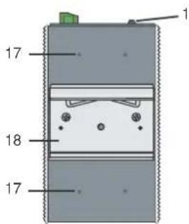
Rear Panel View
VPort 254-M-SC
Front Panel View
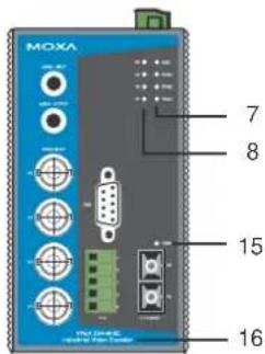
- Grounding screw
- RS-232 console port
- Hardware reset button
- 8-pin terminal block for Relay 1, Relay 2, and power input 2 (PWR2)
- 10-pin terminal block for DI 1, DI 2, DI 3, DI 4, power input 1 (PWR1)
- Heat dissipation orifices
- LEDs for STAT, PWR1, PWR2, FAULT
- LEDs for V1, V2, V3, V4
- AUDIO INPUT port for mic-in and line-in connection
- AUDIO OUTPUT port for external speaker
- RS-232/422/485 COM port with DB9 male connector for PTZ camera or serial device control
- RS-232/422/485 PTZ port with 5-pin terminal block for PTZ camera control
- 4 BNC connectors for video input
- RJ45 10/100BaseTX Ethernet port with 10 Mbps, 1000 Mbps LEDs
- 100BaseFX fiber optic port with 100 Mbps LED
- Model name
- Screw hole for wall mounting kit
- DIN-Rail mounting kit
Product Description
BNC video input/output
The BNC video input is a 1Vpp, 75-ohm video port for connecting an external camera. To ensure that the correct video modulation type is detected, cameras should be connected and powered on before the VPort is powered on.
NOTE
Please use the standard CCTV cable (RG59U or above) to connect the video camera and VPort's BNC connector.
RCA phone jacks for audio input/output
The VPort 254 has 2 RCA phone jacks for audio input and output on the front panel. One jack is for a MIC-in/Line-in audio input connection, which can be directly connected with a microphone or an audio source from an amplifier. The other jack is a Line-out audio output connection, which can be used to connect earphones or an amplifier.
LED indicators
The front panel of the VPort 254 contains several LED indicators. The function of each LED is described in the table below.
| LED Color State Description | |||
| STAT | RED | ON | Hardware initialization |
| FLASHING | Software initialization | ||
| GREEN | ON | System boot-up | |
| FLASHING | Firmware upgrade proceeding | ||
| PWR1 | AMBER | On Power is being supplied to power input PWR1 | |
| Off | Power is not being supplied to power input PWR1 | ||
| PWR2 | AMBER | On Power is being supplied to power input PWR2 | |
| Off | Power is not being supplied to power input PWR2 | ||
| FAULT | RED | On | Three conditions could cause the LED to light up:1. One of the 2 power inputs is disconnected.2. Video loss3. Network disconnectedSettings can be modified on the System Configuration → Alarm → System Alarm page. |
| Off | Both power inputs are connected and working, or there is no video loss, or the network disconnected alarm is silent (if it is activated). | ||
| V1 V2V3 V4 | GREEN | On Video signal has been detected | |
| Off Video signal has not been detected | |||
10/100 Mbps Ethernet port or 100 Mbps fiber optic Ethernet port
The VPort 254 series of video encoders come in three models: the VPort 254 has 1 RJ45 10/100M Ethernet port (LEDs on the left corners of the port indicate 10M or 100M), the VPort 254-S-SC has a single mode fiber optic Ethernet port, and the VPort 254-M-SC has one multi mode fiber optic Ethernet port. Choose the model that is most appropriate for your own application.
RS-232/RS-422/RS-485 PTZ port
The VPort 254 has 1 PTZ port for PTZ control. This PTZ port is an RS-232/RS-422/485 serial port with 5 pin terminal block connector. The pin assignments are as follows:
| PIN | RS-422/485 | RS-232 | ||
| 1 | GND | Ground | GND | Ground |
| 2 | R- | Rx- --- | N/A | |
| 3 | R+ | Rx+ | RxD | RxD |
| 4 | T-/D- | Tx-/ Data- --- | N/A | |
| 5 | T+/D+ | Tx+/ Data+ | TxD | TxD |
To enable PTZ control, users should configure the PTZ control protocol in the web console.
NOTE
The PTZ control protocol is not standardized. To use a particular PTZ control protocol, the video encoder must support the driver for that protocol. Currently, the VPort 351 supports PTZ control protocol drivers for:
- Pelco D
- Pelco P
- Dynacolor DynaDome
In addition, there is an item named “Transparent PTZ Control” in the camera driver list, which is used to transmit the PTZ control signal through the TCP/IP network to the VPort D351 video decoder or PC (additional Real COM driver required), and the PTZ control panel or keyboard can directly control the PTZ camera or device. In this way, there is no need for a PTZ camera driver and better than that, you are not limited because you don’t have a particular protocol.
In addition, to using a protocol that is not on the list, you will need to contact the manufacturer of the camera to get the PTZ control commands, and then use the VPort 254's custom camera function to program the PTZ control.
NOTE
The VPort 254 comes with a PTZ driver upload function for implementing new PTZ drivers. Please contact a Moxa sales representative if you need assistance from Moxa's R&D department to create a new PTZ driver.
RS-232/RS-422/RS-485 COM port
The VPort 254 has 1 COM port for connecting a PTZ motorized camera or serial device. The COM port transmits RS-232 or RS-422/485 signals over the TCP/IP network. Users can use this COM port (DB9 male connector) to monitor data or control a serial device, or for the control of a PTZ motorized camera. The pin assignments are as follows:
| PIN RS-232 | RS-4224-wire RS-485 | 2-wireRS-485 | |
| 1 DCD | TxD-(A) | --- | |
| 2 RXD | TxD-(B) | --- | |
| 3 TXD | RxD-(B) | Data+(B) | |
| 4 DTR | RxD-(A) Data-(A) | ||
| 5 GND | GND | GND | |
| 6 DSR | --- | --- | |
| 7 RTS | --- | --- | |
| 8 | CTS | --- | --- |
| 9 | --- | --- | --- |
Redundant 12/24 VDC and 24 VAC power inputs
The VPort 254 has two power inputs to provide redundancy. Each power input support both 12/24 VDC and 24 VAC power for greater versatility.
NOTE
The supported power input specifications for the VPort 254 series are 12-32 VDC for a 12/24 VDC power input, or 18-30 VAC for a 24 VAC power input. This differs from the Moxa EDS switch's 12-45 VDC power input.
General I/O Terminal Blocks
A 8-pin terminal block and an 10-pin terminal block are located on the VPort 254's top panel. The terminal blocks provide 4 digital inputs (DI), 2 relay outputs (Relay), and 2 power inputs. The digital inputs and relay outputs are for linking to peripheral devices, such as sensors and alarms. These I/O connections can be employed when using the VPort 254 to create an intelligent alarm system for system operation (power failure, video loss, disconnected network) or triggered event (VMD).
| Relay Output | [8264] | Normal Open | Max. 1A, 24 VDCInitial status is Normal Open |
| Common | |||
| Normal Close | |||
| Digital Input | ⊥ | DI- | “High”: +13V to +30V“Low”: -30V to +3V |
| I1, I2 | DI+ |
NOTE
T Please refer to the VPort 254's Quick Installation Guide to learn how to wire the digital inputs and relay outputs.
RS-232 Console Port
The VPort 254 has one RS-232 (10-pin RJ45) console port located on the top panel. Use either an RJ45-to-DB9 cable or RJ45-to-DB25 cable to connect the VPort 254's console port to your PC's COM port. You may then use a console terminal program, such as Moxa PComm Terminal Emulator, to access the VPort 254's console configuration utility.
Reset Button
A recessed RESET button is provided for rebooting and restoring the system to the factory default settings. Use a pointed object, such as a straightened paper clip or toothpick, to press the reset button.
1. Reboot:
To reboot the VPort 254, power it off and then power it back on again, or push the RESET button one time. The STAT LED will light in red as the POST (Power On Self Test) process runs. When the rebooting process is finished, the STAT LED will change to a green color.
2. Restore to Factory Settings:
A recessed RESET button is provided for restoring the system to the factory default settings. When the system fails to install properly, or operates abnormally, use the RESET button located on the top panel of the VPort 254 to restore the factory defaults.
To do this, use a pointed object such as a straightened paper clip or toothpick to hold in the reset button, and then release the reset button when the STAT LED stops flashing in red. At this point, the POST process will run, and the VPort will reboot. The STAT LED will illuminate in green when the VPort has finished rebooting.
This chapter includes information about how to install a VPort 254 video encoder.
The following topics are covered:
Before Getting Started
☐ Initial Installation and Configuration
RS-232 Console Configuration (115200, None, 8, 1, VT1 00)
□ Mounting the VPort
▶ DIN-Rail Mounting
▶ Wall Mounting
□ Wiring Requirements
▶ Grounding the VPort 254
➢ Wiring the Redundant Power Inputs
Wiring the Digital Inputs
RS-232 Connection
10/100BaseT(X) Ethernet Port Connection
➢ 100BaseFX Ethernet Port Connection
COM port
PTZ Port
Before Getting Started
In what follows, “user” refers to those who can access the video encoder, and “administrator” refers to the person who knows the root password that allows changes to the Video Encoder’s configuration, in addition to providing general access. Administrators should read this part of the manual carefully, especially during installation.
Initial Installation and Configuration
Before installing the VPort 254, check to make sure that all items in the package checklist are in the box. In addition, you will need access to a notebook computer or PC equipped with an Ethernet port.
Step 1: Select the power source
The VPort 254 can be powered by a DC power input from 12 to 32 VDC, or an AC power input from 18 to 30 VAC. Two power inputs are provided for redundancy. Users can check the LED status located in the front panel to see if the power inputs are connected appropriately. If one of the power inputs fails, the FAULT LED will light up in red if the power failure alarm is enabled.
NOTE
The VPort 254 series support power input specifications of 12-32 VDC for 12/24 VDC power input, or 18-30 VAC for 24 VAC power input (note that this is different from Moxa EDS switch's 12-45 VDC power input).
Step 2: Connect the VPort 351 to a Network
The VPort 254 has an auto-sensing 10/100 Mbps RJ45 Ethernet port, or 100 Mbps fiber optic port (multi mode or single mode) for network connectivity. Both the RJ45 port and fiber optic port have separate LEDs for 10 Mbps and 100 Mbps connections.
Step 3: Connect the VPort 254 to camera and an audio source
The VPort 254 has 4 VIDEO INPUT ports (V1, V2, V3, V4). Use the BNC connector (1.0 Vpp, 75Ω) and coaxial cable to connect video cameras to the VPort to input analog video signals.
The VPort 254 has 1 audio input and 1 audio output. A microphone or an amplifier can be plugged directly into the AUDIO INPUT port, and a speaker can be plugged into the AUDIO OUTPUT port.
NOTE
Four LEDs (V1, V2, V3, and V4) are located on the VPort 254's front panel to indicate the video signal transmission status for video inputs. Check the LED status to see if the video is working properly.
Step 4: Connecting motorized PTZ cameras and serial devices
The VPort 254 has 2 RS-232/422/485 ports. One is a COM PORT with DB9 male connector, and the other is a PTZ PORT with 5-pin terminal block connector. Both ports can be used for connecting PTZ control cables for controlling PTZ cameras over the TCP/IP network.
In addition, the COM PORT with DB9 male connector can also be used to connect general serial devices, such as card readers, for transmitting serial data over a TCP/IP network. This port can be used to connect serial devices to the VPort 254 (however, the port cannot be used to connect video cameras).
To enable PTZ control, users should configure the PTZ control protocol in the web-based manager.
Legacy PTZ Camera Control
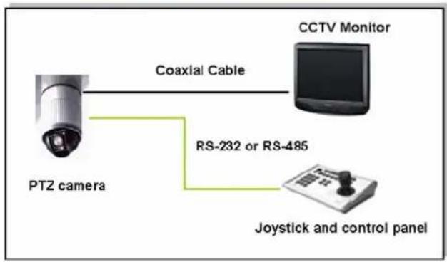
flowchart
graph LR
    A["PTZ camera"] -->|Coaxial Cable| B["CCTV Monitor"]
    A -->|RS-232 or RS-485| C["Joystick and control panel"]
Transparent PTZ Camera Control via Ethernet
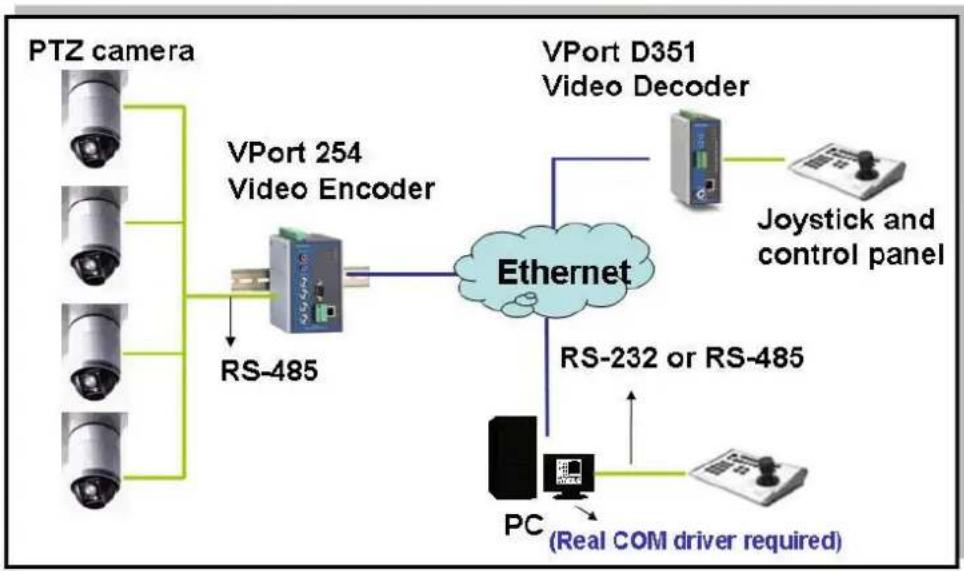
flowchart
graph TD
    A["PTZ camera"] --> B["VPort 254 Video Encoder"]
    C["PTZ camera"] --> B
    D["PTZ camera"] --> E["RS-485"]
    F["PTZ camera"] --> E
    G["VPort D351 Video Decoder"] --> H["Ethernet"]
    I["Joystick and control panel"] --> H
    J["PC (Real COM driver required)"] --> H
    H --> K["RS-232 or RS-485"]
| NOTE | The PTZ control protocol is not standardized. To use a particular PTZ control protocol, the video server must support the driver for that protocol. Currently, the VPort 254 supports PTZ control protocol drivers for:1. Pelco D2. Pelco P3. DynaColor DynaDomeIf you need to use a protocol that is not on the list, contact the manufacturer of the camera to get the PTZ control commands, and then program its PTZ control using the VPort 254’sCustom Camera function. |
| NOTE | The VPort 254 comes with a PTZ driver upload function for implementing new PTZ drivers. Please contact a Moxa sales representative if you need assistance from Moxa’s R&D department to create a new PTZ driver. |
| NOTE | The “Transparent PTZ Control” function in the camera driver list is used to transmit the PTZ control signal over a TCP/IP network to the VPort D351 video decoder or PC (additional driver required). The PTZ control panel or keyboard can directly control the PTZ camera or device, eliminating the need for a PTZ camera driver and allowing the use of PTZ cameras with the VPort encoder. |
Step 5: Configure the VPort 254's IP address
After powering on the VPort 254, wait a few seconds for the POST (Power On Self Test) to run. The STAT LED turns green to indicate that the POST process has completed. The IP address will be assigned when the 10 or 100 Mbps NETWORK LED blinks. The IP address assigned after the POST is completed depends on the network environment.
Network Environment with DHCP Server
In this case, the IP address of the VPort 3310 is assigned by a DHCP Server. Use the DHCP Server's IP address table, or use the Moxa VPort utility to determine the IP address that was assigned by the DHCP Server.
| NOTE | After powering on the VPort 254, wait a few seconds for the POST (Power On Self Test) to run. The IP address will be assigned when the 10 or 100 Mbps NETWORK LED blinks. |
Using the Moxa VPort and Ether Device Configurator Utility (edscfgui.exe), as described below:
- Run the edscfgui.exe program to search for the VPort and EDS switches. After the Utility window opens, you may also select or click on Broadcast Search, which is located under the List Server menu, to initiate a search (note that you can also click on the Broadcast Search icon 📷 to initiate a search.
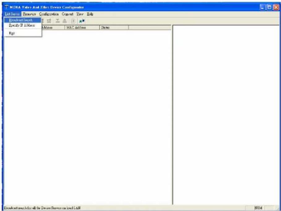
NOTE
You may download the Moxa VPort and EtherDevice Configurator Utility (edscfgui.exe) software from Moxa's website at www.moxa.com.
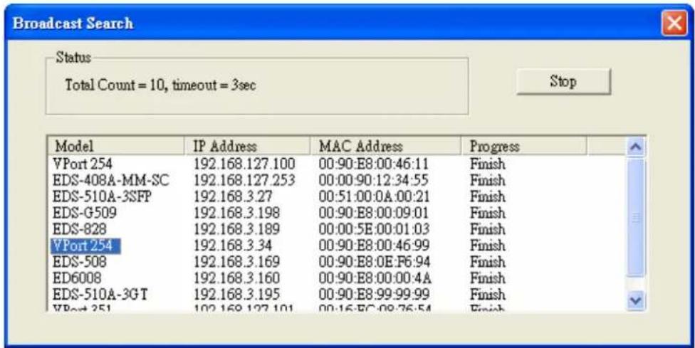
- The Broadcast Search window will show a list of all switches and VPorts located on the network. The progress of the search will also be indicated.
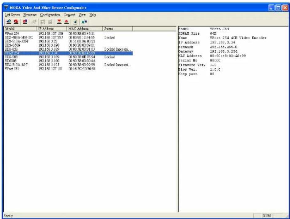
- When the search has ended, the Model Name, MAC address, and IP address of the EDS Switch and VPort will be listed in the Utility window.
NOTE
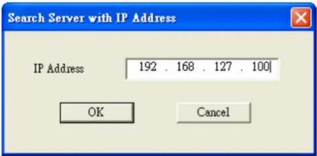
Broadcast Search can only be used to search for devices on the same LAN domain. If your devices are located on a different LAN domain, use Specify IP Address to search for the device by keying in the IP address.
- Double click the selected VPort, or use Internet Explorer to access the VPort's web-based manager (web console).
Network Environment without a DHCP Server:
If your VPort 254 is connected to a network that does not have a DHCP server, then you will need to configure the IP address manually. The default IP address of the VPort 351 is 192.168.127.100 and the default subnet mask is 255.255.255.0. Note that you may need to change your computer's IP address and subnet mask so that the computer is on the same subnet as the VPort.
To change the IP address of the VPort manually, access the VPort's web server, and then navigate to the System Configuration → Network → General page to configure the IP address and other network settings. Check the Use fixed IP address to ensure that the IP address you assign is not deleted each time the VPort is restarted.
Step 6: Log into the ActiveX Control Plug-in
Type the IP address in the web browser's address input box and then press enter.
Step 7: Install the ActiveX Control plug-in
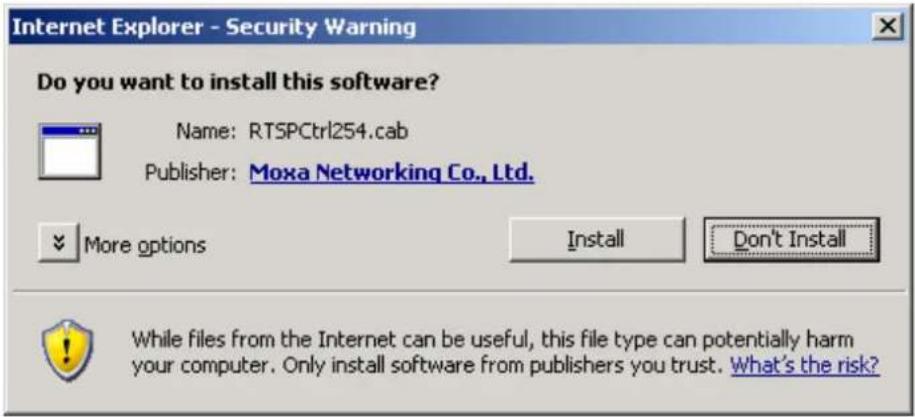
A security warning message will appear the first time you access the VPort's web-based manager. The message is related to installing the VPort AcitveX Control component to your PC or notebook. Click on Yes to install this plug-in to enable the IE web browser for viewing video images.
NOTE
For Windows XP SP2 or above operating systems, the ActiveX Control component will be blocked for system security reasons. In this case, the VPort's security warning message window may not appear. Users should unblock the ActiveX control function or disable the security configuration to enable the installation of VPort's ActiveX Control component.
Step 8: Accessing the homepage of the VPort 254's web-based manager
After installing the ActiveX Control component, the homepage of the VPort 254's web-based manager will appear. Check the following items to make sure the system was installed properly:
- Video Images
- Audio Sound (make sure your PC's or notebook's sound is turned on)
- Video Information

![VPort 254 Series Video Encoder Model Name: VPort 254 Server Name: VPort 254 4CH Video Encoder IP Address : 192.168.3.28 MAC Address : 00:00:08:00:06:11 Firmware Version: 1.0 State Power1 Power2 Fault Channel 1 Channel 2 Channel 3 Channel 4 Client Setting System Configuration Show P/Z Control Panel Video Information Encode Type : HIPEG Video Size : 2.2mm/4mm File video quality : Excellent Max. FPS : 7 FPS Status : 2 Relay Control Relay 1 Open Close Relay 2 Open Close Snapshot Channel 1 Channel 2 Channel 3 Channel 4 Best revised with EC 0.0 or above with resolution of 1280x1024 VPort 254 4CH Video Encoder [AV-UDP] 1999/11/30 00:01:24 [AV-UDP] 1999/11/30 00:01:24 [AV-UDP] 1999/11/30 00:01:24 [AV-UDP] 1999/11/30 00:01:24 完成 ©©©©6 ¥1,009](/content/2026/06/1281137/images/e5f031d170157d8d70c3cd4e13b49b41cebef0d306194503f2ca168863e3c022.jpg)
Step 9: Accessing the VPort's System Configuration
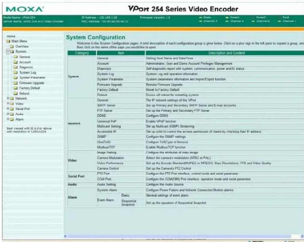
Click on System Configuration to access the overview of the system configuration to change the configuration. Model Name, Server Name, IP Address, MAC Address, Firmware Version, and LED Status appear in the green bar near the top of the page. Use this information to check the system information and installation.
For details of each configuration, check the User's Manual on the software CD.
NOTE
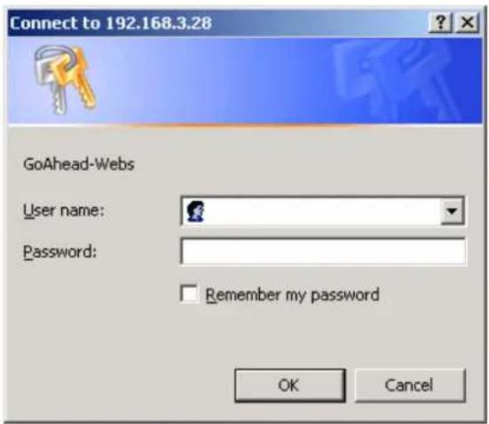
After accessing the VPort 254's web-based manager, administrators should access System Configuration → System → Account to set up the administrator's password and enable the authentication function. The administrator account name is admin.
An authentication window will pop up requesting the account name and password each time the VPort 254 is accessed.
RS-232 Console Configuration (115200, None, 8, 1, VT1 00)
NOTE
-
You cannot connect to the VPort 254 simultaneously by serial console and Telnet.
-
You may connect to the VPort 254 simultaneously by web browser and serial console, or by web browser and Telnet. However, we strongly recommend that you use only one connection method at a time. This allows you to maintain better control over your VPort 351's configuration.
You can access the RS-232 console by using a terminal emulator on your PC. We recommend that you use PComm Terminal Emulator, which is free and can be downloaded from Moxa's website. The following instructions explain how to use PComm to access the RS-232 console.
-
Use an RJ45 to DB9-F (or RJ45 to DB25-F) cable to connect the VPort 254's RS-232 console port to a COM port on your PC.
-
From the Windows desktop, click Start → Programs → PCommLite2.5 → Terminal Emulator.
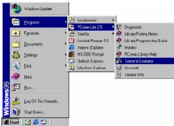
- Select Open under Port Manager to open a new connection.

- The Communication Parameter page of the Property window opens. Select the appropriate COM port for Console Connection, 115200 for Baud Rate, 8 for Data Bits, None for Parity, and 1 for Stop Bits.
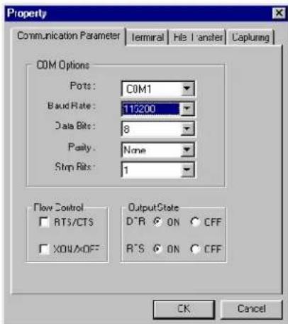
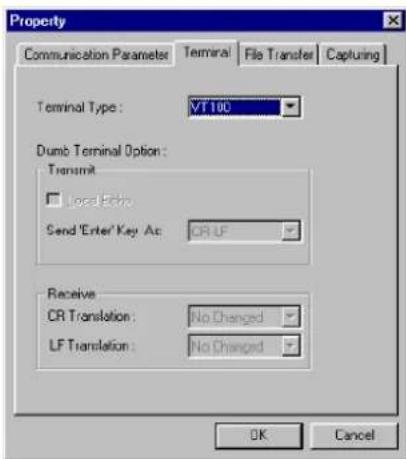
- Click the Terminal tab, and select VT100 for Terminal Type. Click OK to continue.
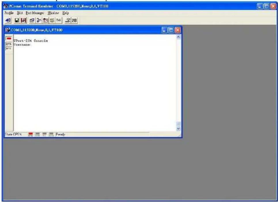
- A blank screen will appear. Press Enter, after which a login message will appear. Only the administrator is allowed to use this console configuration. Use admin as the username and the associated admin password as the password. Press Enter to continue.
- The RS-232 console's Main Menu will be displayed.
(NOTE: To modify the appearance of the PComm Terminal Emulator window, select Font... under the Edit menu, and then choose the desired formatting options.)
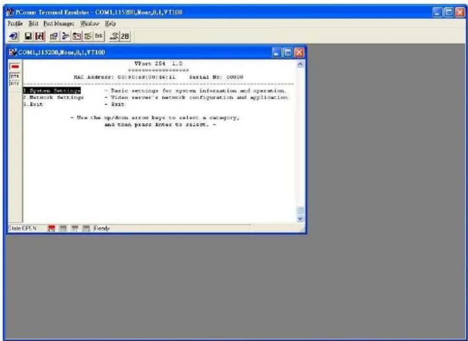
- After entering the Main Menu, use the following keys to move the cursor, and to select options.
| Key | Function |
| Up/Down/Left/Right arrows, or Tab Move the onscreen cursor | |
| Enter Display & select options | |
| Space | Toggle |
| Esc | Previous |
options
Menu
NOTE
Many settings are related to video images, which cannot be shown on the RS-232 console. The VPort 254's RS-232 console provides only Basic System Setting and Network Setting. For more advanced configuration, please use the web console.
Mounting the VPort 254 Dimension
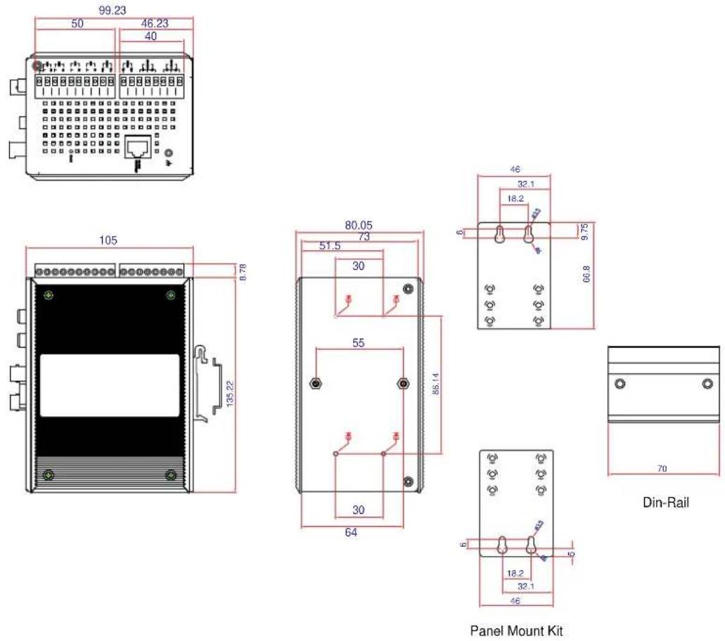
(Unit=mm)
DIN-Rail Mounting
The DIN-Rail attachment plate should already be attached to the back panel of the VPort 254 when you take it out of the box. If you need to reattach the plate, make sure the metal spring is situated towards the top, as shown in the figures below.
STEP 1:
Insert the top of the DIN-Rail into the slot just below the metal spring.
STEP 2:
The unit will snap into place as shown below.
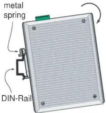
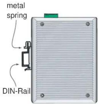
Reverse Steps 1 and 2 above to remove the VPort 254 from the DIN-Rail.
Wall Mounting
Follow the steps below to mount the VPort 254 on a wall or panel.
STEP 1:
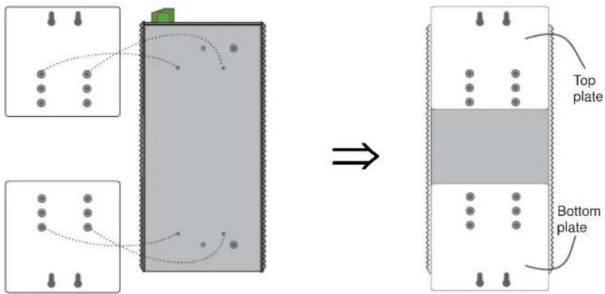
Remove the DIN-Rail attachment plate from the VPort 254. Attach the two wall-mount plates as shown in the diagrams below.
STEP 2:
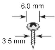
Mounting the VPort 254 on the wall requires 4 screws. Use the VPort 254, with wall mount plates attached, as a guide to mark the correct locations of the 4 screws. The heads of the screws should be less than 6.0 mm in diameter, and the shafts should be less than 3.5 mm in diameter, as shown in the figure at the right.
Do not screw the screws in all the way—leave a space of about 2 mm to allow room for sliding the wall mount panel between the wall and the screws.
NOTE
Before you mount the unit on the wall, make sure that the screws are the right size by testing them with the apertures on the mounting plates.
STEP 3:
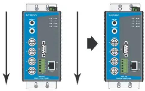
Once the screws are fixed in the wall, insert the four screw heads through the large parts of the keyhole-shaped apertures, and then slide VPort 254 downwards, as indicated in the figure. Tighten the four screws for added stability.
flowchart
graph TD
    A["MOXA"] --> B["Device 1: Switch"]
    B --> C["Device 2: USB port"]
    C --> D["Device 3: USB port"]
    D --> E["Device 4: USB port"]
    E --> F["Device 5: USB port"]
    F --> G["Device 6: USB port"]
    G --> H["Device 7: USB port"]
    H --> I["Device 8: USB port"]
    I --> J["Device 9: USB port"]
    J --> K["Device 10: USB port"]
    K --> L["Device 11: USB port"]
    L --> M["Device 12: USB port"]
Wiring Requirements

ATTENTION
Be sure to disconnect the power cord before installing and/or wiring your Moxa VPort 254.
Calculate the maximum possible current in each power wire and common wire. Observe all electrical codes dictating the maximum current allowable for each wire size.
If the current goes above the maximum ratings, the wiring could overheat, causing serious damage to your equipment.
You should also pay attention to the following:
- Use separate paths to route wiring for power and devices. If power wiring and device wiring paths must cross, make sure the wires are perpendicular at the intersection point.
NOTE: Do not run signal or communications wiring and power wiring in the same wire conduit. To avoid interference, wires with different signal characteristics should be routed separately. - You can use the type of signal transmitted through a wire to determine which wires should be kept separate. The rule of thumb is that wiring that shares similar electrical characteristics can be bundled together.
- Keep input wiring and output wiring separated.
- It is strongly advised that you label wiring to all devices in the system when necessary.
Grounding the VPort 254
Grounding and wire routing help limit the effects of noise due to electromagnetic interference (EMI). Run the ground connection from the ground screw to the grounding surface prior to connecting devices.

ATTENTION
This product is intended to be mounted to a well-grounded mounting surface such as a metal panel.
Wiring the Redundant Power Inputs
The VPort 254 has two sets of power input, power input 1 and power input 2, which are located on the 6-pin and 8-pin terminal block connectors. Top and front views of the terminal block connectors are shown here.
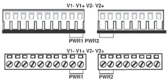
STEP 1: Insert the negative/positive DC or AC wires into the V-/V+ terminals.
STEP 2: To keep the DC or AC wires from pulling loose, use a small flat-blade screwdriver to tighten the wire-clamp screws on the front of the terminal block connector.
STEP 3: Insert the plastic terminal block connector prongs into the terminal block receptor, which is located on the VPort 351's top panel.

ATTENTION
The power for this product is intended to be supplied by a Listed Power Unit, with output marked LPS, and rated to deliver 12 to 32 VDC at a maximum of 740 mA, or 18 to 30 VAC at a maximum of 890 mA.

ATTENTION
Before connecting the VPort to the AC/DC power inputs, make sure the DC power source voltage is stable.
Wiring the Relay Output
The VPort 254 has two sets of relay output, relay 1 and relay 2, which are located on the 8-pin terminal block connector. Each relay output consists of the 3 contacts of the terminal block on the VPort 254's top panel.
The relay output can be set up for:
-
System alarm: Power failure, Video loss and Network disconnected.
-
Event alarm: VMD (Video Motion Detection) and Digital Inputs (firmware version V2.0 and later)
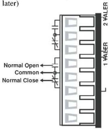

ATTENTION
The current and power capacity of the relay output is a maximum of 24 VDC @ 1A. You should be careful not to exceed this power specification.
Wiring the Digital Inputs
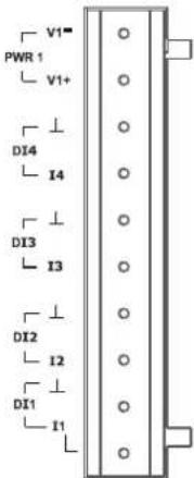
VPort 254 has four sets of digital input, DI1, DI2, DI3 and DI4. Each DI consists of two contacts of the 10-pin terminal block connector on VPort's top panel. Top and front views of one of the terminal block connectors are shown here.
STEP 1: Insert the negative (ground)/positive DI wires into the ⊥/I1 terminals.
STEP 2: To keep the DI wires from pulling loose, use a small flat-blade screwdriver to tighten the wire-clamp screws on the front of the terminal block connector.
STEP 3: Insert the plastic terminal block connector prongs into the terminal block receptor, which is located on VPort 254's top panel.
RS-232 Connection
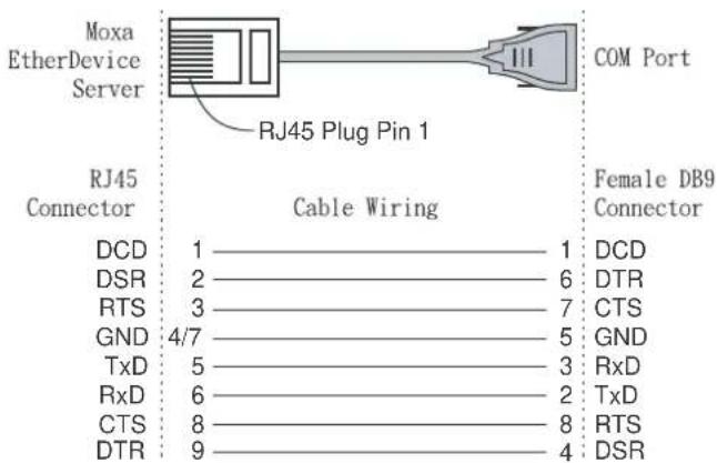
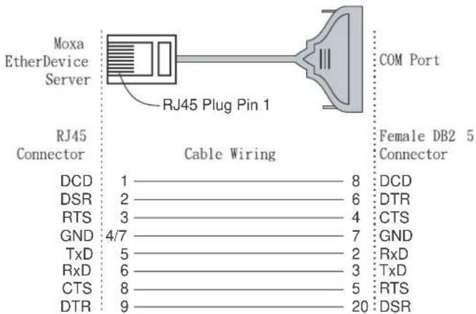
The VPort 254 has one RS-232 (10-pin RJ45) console port, located on the top panel. Use either an RJ45-to-DB9 or RJ45-to-DB25 cable (see the cable following wiring diagrams) to connect the VPort 254's console port to your PC's COM port. You may then use a console terminal program, such as Moxa PComm Terminal Emulator, to access the VPort 254's console configuration utility.
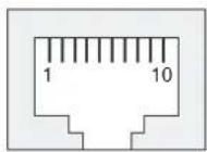
RJ45 (10-pin) Console Port Pinouts
| Pin | Description |
| 1 | --- |
| 2 | DSR |
| 3 | --- |
| 4 | GND |
| 5 | TxD |
| 6 | RxD |
| 7 | GND |
| 8 | --- |
| 9 | DTR |
| 10 | --- |
RJ45 (10-pin) to DB9 (F) Cable Wiring
RJ45 (10-pin) to DB25 (F) Cable Wiring
10/100BaseT(X) Ethernet Port Connection
The 10/100BaseT(X) port located on the VPort 254's front panel is used to connect to Ethernet-enabled devices.
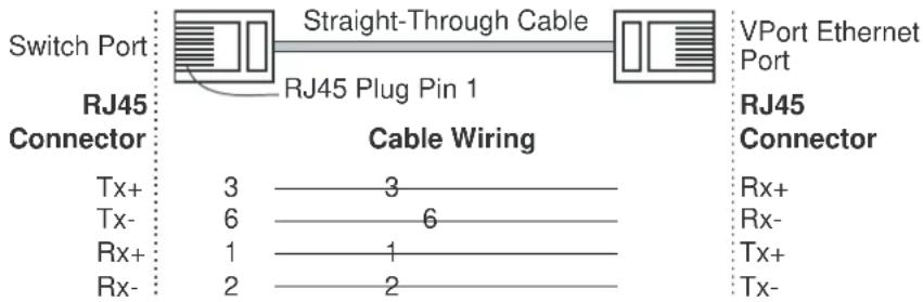
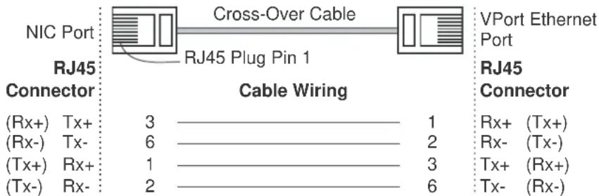
The following table shows pinouts for both MDI (NIC-type) ports and MDI-X (HUB/Switch-type) ports. We also show cable wiring diagrams for straight-through and cross-over Ethernet cables.
(MDI) Port Pinouts
| Pin | Signal |
| 1 | Tx+ |
| 2 | Tx- |
| 3 | Rx+ |
| 6 | Rx- |
(MDI-X) Port Pinouts
| Pin | Signal |
| 1 | Rx+ |
| 2 | Rx- |
| 3 | Tx+ |
| 6 | Tx- |
8-pin RJ45
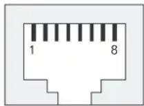
RJ45 (8-pin) to RJ45 (8-pin) Straight-Through Cable Wiring
RJ45 (8-pin) to RJ45 (8-pin) Cross-Over Cable Wiring
100BaseFX Ethernet Port Connection
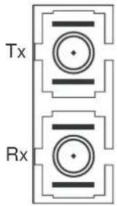
The concept behind the SC port and cable is easy to understand. Since optical signals do not require a circuit to transmit data, one cable is used to transmit data and one cable is used to receive data, providing full-duplex transmission.
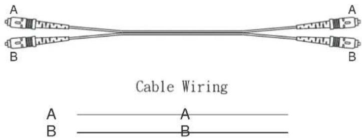
Remember to connect the Tx (transmit) port of device I to the Rx (receive) port of device II, and the Rx (receive) port of device I to the Tx (transmit) port of device II. If you make your own cable, we suggest labeling the two sides of the same line with the same letter (A-to-A and B-to-B, as shown below, or A1-to-A2 and B1-to-B2).
SC-Port Pinouts SC-Port to SC-Port Cable Wiring
A COM PORT is located on the front panel for connecting a PTZ motorized camera or serial device. The COM port transmits RS-232 or RS-422/485 signals over the TCP/IP network. Users can use this COM port (DB9 male connector) to monitor data or control a serial device, or for the control of a PTZ motorized camera.
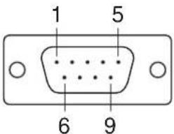
RS-232/422/485 (Male DB9) Pinouts
| PIN RS-232 | RS-422 4-wire RS-485 | 2-wire RS-485 | |
| 1 | DCD | TxD-(A) | --- |
| 2 | RxD | TxD+(B) | --- |
| 3 | TxD | RxD+(B) | Data+ |
| 4 | DSR | RxD-(A) | Data-(A) |
| 5 | GND | GND | GND |
| 6 | DTR | --- | --- |
| 7 | RTS | --- | --- |
| 8 | CTS | --- | --- |
| 9 | --- | --- | |
PTZ Port
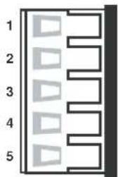
A PTZ port is located on the VPort 254's front panel. The port is used to connect to a PTZ motorized camera or device, so that the camera or device can be controlled from the VPort over the IP network. The PTZ port supports RS-232 or RS-422/485 signals through the terminal block. The PTZ port pin assignments are shown in the following table.
Pin Assignment
natural_image
Pure diagram of five vertical panels with triangular shapes, no text or symbols present| PIN RS-422/485 RS-232 | ||
| 1 | GND | |
| 2 | R- | |
| 3 | R+ | |
| 4 | T-\D- | |
| 5 | T+\D+ | |
Accessing VPort 254's Web-based Manager
This chapter includes information about how to access VPort 254 Video Encoder for the first time. The following topics are covered:
□ Functions Featured on the VPort's Web Homepage
- VPort's Information
Server Name
➢ Camera Image View
▶ Audio Control
▶ Client Setting
System Configuration
▶ Video Information
PTZ Control PanelPTZ (Motorized) Camera Control
➢ Custom PTZ Camera Commands
▶ Video Image Snapshots
▶ Relay Control
Functions Featured on the VPort's Web Homepage
The homepage of the VPort's web console shows information specific to that VPort, the camera image, and configurations for client and server.
NOTE
The VPort's web homepage is best viewed using a 1280 x 1024 screen size. This is because the camera image can be viewed at a resolution up to Full D1 (NTSC: 720 x 480; 720 x 576). We strongly recommend using IE 6.0 (Microsoft Internet Explorer) or above to avoid incompatibility with the ActiveX Plug-in.
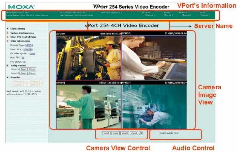
VPort's Information
This section shows the VPort's model name, server name, IP address, MAC address, firmware version, and the display status of the LEDs located on the VPort's front panel.
NOTE
The VPort LEDs shown on the VPort's web homepage are updated every 10 seconds.
Server Name
A server name can be assigned to each server. Administrators can change the name in System Configuration/System/General. The maximum length of the sever name is 40 bytes.
Camera Image View
The assigned image description and system date/time will be displayed in the caption above the image window. You may disable the caption or change the location of the image information from the System Configuration/Video/Image Setting. Note that if the VPort's motion detection function is active, some windows in the video picture might be framed in red.
Audio Control
The VPort 254 provides both audio input and audio output for voice over IP communication. Client users can directly enable and disable the audio input (a microphone, for example) by clicking the microphone button, and audio output (a speaker, for example) by clicking the speaker button from the VPort's web homepage. You may also use the Client Setting to disable the audio transmission.
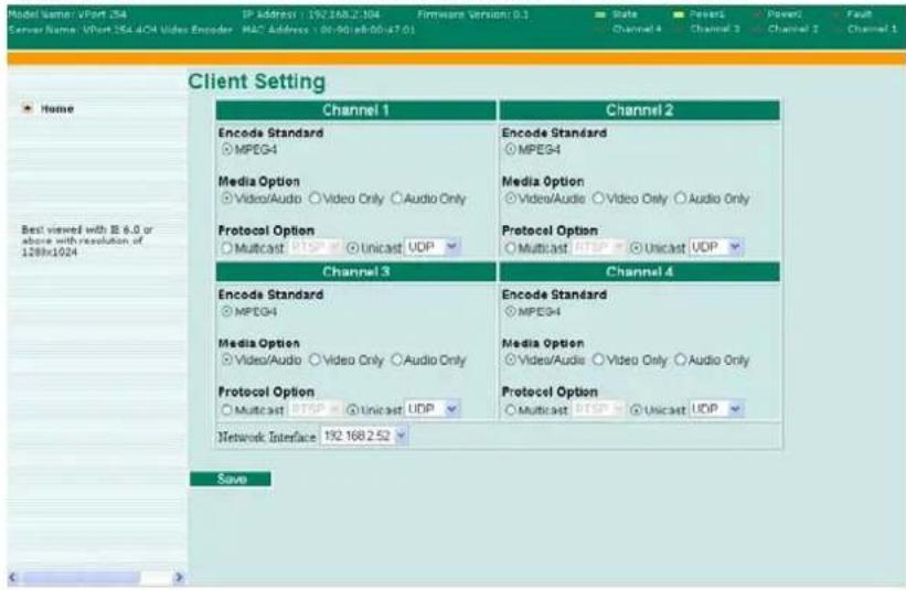
Client Setting
Users can configure the following functions in Client Settings.
- Encoder standard: Shows the encode algorithm currently being used.
- Media Options: Enable or disable the video or audio transmission.
- Protocol Options: Choose one of four protocols to optimize your usage—Multicast (RTSP or Push) or Unicast (UDP, TCP, HTTP).
- Multicast protocol can be used to send a single video stream to multiple clients. In this case, a lot of bandwidth can be saved since only one video stream is transmitted over the network. However, the network gateway (e.g., a switch) must support multicast protocol (e.g., IGMP snooping). Otherwise, the multicast video transmission will not be successful.
- RTSP: Enable the multicast video stream to be sent in RTSP control, which means the multicast video stream will be sent only it receives the client's request.
- Push: Enable the multicast video stream to be sent in Push control, which means the multicast video stream will be sent continuously after this setting is selected.
- Unicast protocol is used to send a single video stream to one client.
- UDP protocol can be used to produce audio and video streams that are more real-time. However, some packets may be lost due to network burst traffic, and images may become blurred.
- TCP protocol can be used to prevent packet loss, which results in a more accurate video display. The downside of using TCP is that the real-time effect is worse than with UDP protocol.
- HTTP protocol can be used to prevent being blocked by a router's firewall. The downside of using HTTP is that the real-time effect is worse than with UDP protocol.
Once the video encoder is connected successfully, Protocol Options will indicate the selected protocol. The selected protocol will be recorded on the user's PC, and will be used for the next connection.
NOTE
For multicast video stream setting, please refer to System Configuration → Network → Multicast.
MOXA®
VPort 254 Series Video Encoder
System Configuration
A button or text link on the left side of the system configuration window only appears on the administrator's main page. For detailed system configuration instructions, refer to Chapter 4, System Configuration.
Video Information
Users can easily monitor the current video performance by looking at the Video Information shown on the left side of the homepage. The following properties are shown: Video Size, Video Quality (Fixed bit rate or Fixed video quality), Max. FPS (frames per second), and (current) FPS Status. Users can select the target camera image to view each camera's video performance.
PTZ Control Panel
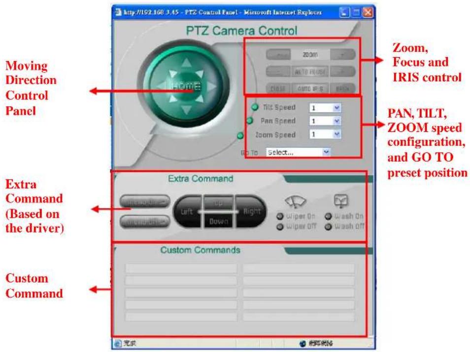
Users can click this link to pop up a new window for PTZ Control. To select a camera, click the target camera's image view.
PTZ (Motorized) Camera Control
If a serial device, such as a motorized camera, is attached to the COM/PTZ port, the control panel will appear on the main page for user's who have permission to operate the camera. Buttons that are active will change color when the cursor is passed over the button. Users can control the pan, tilt, zoom, and focus functions of motorized cameras. The home button is used to return the camera to the center position if the camera supports this command. In addition to near and far control for focus, an AUTO button is provided for setting auto focus mode. To move the motorized camera more precisely, the speed control for pan and tilt allows users to fine tune the aiming of the camera. Users can also click directly on any point in the image to force the motorized camera to focus on that point, or select a preset location from the drop-down menu. Administrators are able to add or modify the list of preset locations. Details are described in the relevant section in Chapter 4, System Configuration.
NOTE
For some PTZ cameras, users can click on any position in the image to point the camera to that position. We currently support this functionality for Pelco-D, Pelco P and Dynacolor DynaDome PTZ drivers.
Custom PTZ Camera Commands
In addition to the default pan, tilt, zoom, and focus controls, an additional 10 buttons are available for custom commands to control the attached motorized (PTZ) cameras. Custom commands are set up by administrators, and are used for functions such as activating or deactivating the dome wiper. Refer to the attached motorized device's User's Manual to see which functions can be controlled with these additional buttons.
Video Image Snapshots
Users can take snapshot images for storing, printing, or editing by clicking the Channel Snapshot button. To save the image, click the right mouse button and select the Save option.
Relay Control
The VPort 254 has 2 relay outputs for external devices, such as alarms. Administrators and permitted users can click on Open to short the Common and Normal Open digital output pins, or click on Close to short the Common and Normal Close digital output pins.
After installing the hardware, the next step is to configure the VPort 254's settings. Users can configure by web console.
This chapter includes the following sections:
□ System Configuration by Web Console
System
Network
Video
Serial Port
Audio
▶ Alarm
System Configuration by Web Console
System configuration can be done remotely with Internet Explorer. To access the server, type the system configuration URL, http://
There are six configuration categories: System, Network, Video, Serial Port, Audio, and Alarm. A description of each configuration item is shown in the table below:
| Category Item Description and Contents | ||
| System | General Set Host Name and Date/Time | |
| Accounts | Administrator, User, and Demo Account Privileges Management | |
| Diagnosis | Self-diagnostic report with system, communication, power, and LED status | |
| System Log System Log and operation information | ||
| System Parameter | System parameter information and Import/Export functions | |
| Firmware Upgrade Remote Firmware Upgrade | ||
| Factory Default Reset to Factory Default | ||
| Reboot Device will reboot for restarting system | ||
| Network | General The IP network settings of this VPort | |
| SMTP Server | Set up Primary and Secondary SMTP Server and e-mail accounts | |
| FTP Server Set up the Primary and Secondary FTP Server | ||
| DDNS Configure Dynamic DNS service | ||
| Universal PnP Enable UPnP function | ||
| Multicast Setting Set up Multicast (IGMP) Streaming | ||
| Accessible IP | Set up a list to control the access permission of clients by checking their IP address | |
| SNMP | Configure the SNMP settings | |
| ToS | Configure ToS(Type of Service) | |
| Modbus/ TCP | Enable Modbus/TCP function | |
| Video | Image Setting | Configure the attributes of the video image |
| Camera Modulation | Select the camera's modulation (NTSC, PAL or AUTO) | |
| Video Performance | Set up the Size (Resolution), FPS, and Video Quality | |
| Camera Control | Set up the Camera's PTZ Control | |
| Serial port | PTZ port | Configure the PTZ Port interface, control mode, and serial parameters. |
| COM port | Configure the COM (DB9) Port interface, operation mode, and serial parameters. | |
| Audio | Audio Setting | Set up the audio source |
| Alarm | System Alarm | Configure Power Failure and Network Connection Broken alarms |
| Event Alarm | Basic General settings of event alarm | |
| Sequential Snapshot Set up the Sequential Snapshot operation | ||
This table can also be found on the System Configuration → Overview webpage.
MOXA®
VPort 254 Series Video Encoder
| Category | Item | Description and Content |
| System | General | Setting Host Name and Date/Time |
| Account | Administrator, User and Demo Account Privileges Management | |
| Diagnosis | Self-diagnostic report with system, communication, power and IO status | |
| System Log | System Log and operation information | |
| System Parameter | System parameters information and Import/Export function | |
| Firmware Upgrade | Remote Firmware Upgrade | |
| Factory Default | Reset to Factory Default | |
| Robot | Device will reboot for restarting system | |
| Network | General | The IP network settings of this VPort |
| SMTP Server | Set up Primary and Secondary SMTP Server and E-mail accounts | |
| FTP Server | Set up the Primary and Secondary FTP Server | |
| DONS | Configure DONS | |
| Universal PnP | Enable UPnP function | |
| Multicast Setting | Set up Multicast (ICMP) Streaming | |
| Accessible IP | Set up a list to control the access permission of clients by checking their IP ac | |
| SNMP | Configure the SNMP settings | |
| Qcs(ToS) | Configure ToS(Type of Service) | |
| Modbus/TCP | Enable Modbus/TCP function | |
| Video | Image Setting | Configure the attributes of video image |
| Camera Modulation | Select the camera's modulation (NTSC or PAL) | |
| Video Performance | Set up the Encode Standard(MJPEG or MPEG4), Size (Resolution), FPS and |
System
General Settings
On the General Settings page, administrators can set up the video Server name and the Date and Time, which appear in the image's caption.
MOXA®
VPort 254 Series Video Encoder
| Model Name: vPort 254 Server Name: vPort 254 4CH Video Encoder IP Address: 192.168.2.104 Firmware Version: 0.1 MAC Address: 00:90 e8:00:47:01 | |
| Home Main Menu OverView System General Account Diagnosis System Log System Parameter Firmware Upgrade Factory Default Reboot Network Video Serial Port Audio Alarm Best viewed with IE 5.0 or above with resolution of 1280x1024 | |
| General Settings Server name: vPort 254 4CH Video Encoder | |
| Date and Time: Keep current date and time Sync with computer time PC date: 2008/10/05[yyyy/mm/dd] PC time: 10:47:37 [hh:mm:ss] Manual Date: 2008/10/05[yyyy/mm/dd] Time: 05:27:20 [hh:mm:ss] Automatic NTP server: skip to invoke default server Time zone: GMT Update interval: One hour Save |
Server name
| Setting Description Default | ||
| Max. 40 characters | Use a different server name for each server to help identify the different servers. The name appears on the web homepage. | VPort 254 4CH Video Encoder |
Date and Time
| Setting Description Default | ||
| Keep current date and time | Use the current date and time as the VPort's time setting. | Keep current date and time |
| Sync with computer time | Synchronize VPort's data and time setting with the local computer time. | |
| Manual | Manually change VPort's date and time setting. | |
| Automatic | Use the NTP server for changing VPort's date and time setting in a given period. | |
NOTE
Select the Automatic option to force the VPort to synchronize automatically with timeservers over the Internet. However, synchronization may fail if the assigned NTP server cannot be reached, or the VPort is connected to a local network. Leaving the NTP server blank will force the VPort to connect to default timeservers. Enter either the Domain name or IP address format of the timeserver if the DNS server is available.
Don't forget to set the Time zone for local settings. Refer to Appendix G for your region's time zone.
Account Privileges
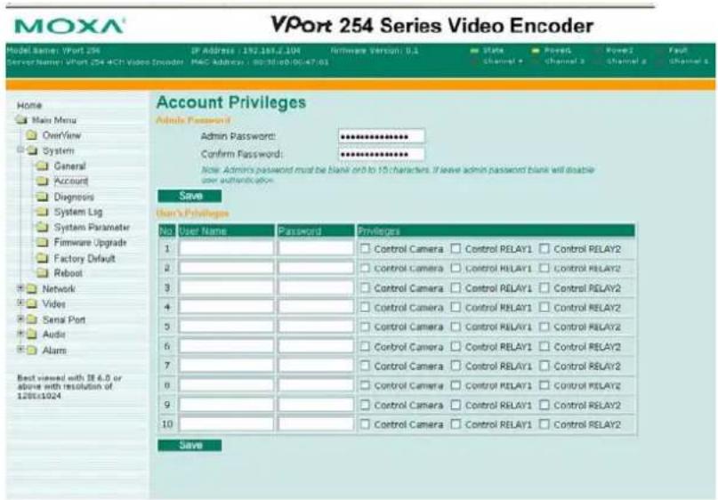
Different account privileges are available for different purposes.
Admin password
| Setting Description Default | ||
| Admin Password (max. 14 characters) | Administrator can type the new password in this box. | Default admin password is “admin” |
| Confirm Password (max. 14 characters) | If a new password is typed in the Admin Password box, you will need to retype the password in the Confirm Password box before updating the new password. | |
NOTE
The default account name for administrator is admin; the administrator account name cannot be changed.
User's Privileges
VPort products provide 10 user accounts for accessing VPort. Administrators can set up user's privileges in this section. Each user can be given independent access right to the external I/O and camera control.
| Setting Description Default | ||
| User Name | Type a specific user name for user authentication. | None |
| Password | Type a specific password for user authentication. | |
| Privilege | Check the function boxes to assign privileges for users in Control Camera, Control Relay1, and Control Relay2. | |
NOTE
The FPS of the video stream will be reduced as more and more users access the same VPort. For this reason, only 8 client users can access the VPort 254 at the same time. Enforcing this kind of restriction helps guarantee the performance of the video stream.
System Diagnosis
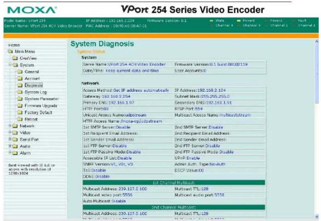
VPort products have a self-diagnosis function to let the administrator get a quick view of the system and connection status. Administrators can save this diagnosis information in a file (diagnosis.log) by clicking the Export to a File button, or send the file via email by clicking the Send a Report via Email button.
System Log History
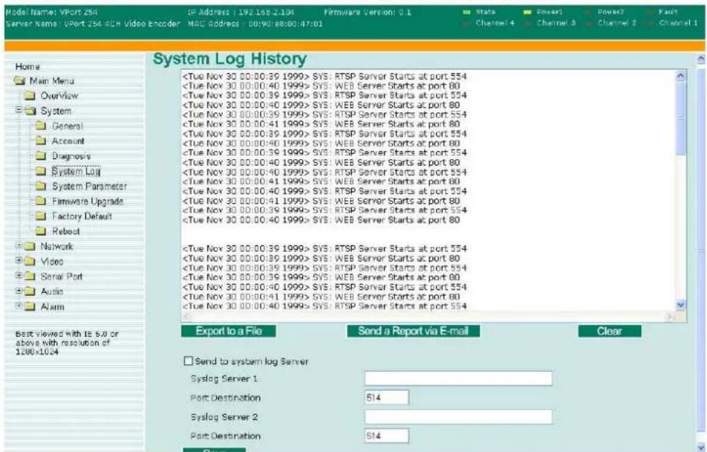
The system log contains useful information, including current system configuration and activity history with timestamp for tracking. Administrators can save this information in a file (system.log) by clicking the Export to a File button, or send the file by email by clicking the Send a Report via Email button. In addition, the log can also be sent to a Log Server for backing up. The administrator can setup the Syslog Server 1 and Syslog server 2 below the system log list.
MOXA®
VPort 254 Series Video Encoder
System Parameters
The System Parameters page allows you to view all system parameters, which are listed by category. The content is the same as the VPort's sys_config.ini file. Administrators can also save this information in a file (sys_config.ini) by clicking the Export to a File button, or import a file by clicking the Browse button to search a sys_config.ini file and the Import a System Parameter File button to update the system configuration quickly.
MOXA®
VPort 254 Series Video Encoder
![Model Name: VPort 254 Server Name: VPort 254 4CH Video Encoder IP Address: 192.168.2.104 Firmware Version: 0.1 MAC Address: 00:90168:00:47:01 State Power1 Power2 Fault Channel 4 Channel 3 Channel 2 Channel 1 Home Main Menu Overview System General Account Diagnosis System Log System Parameter Firmware Upgrade Factory Default Robust Network Video Serial Port Audio Alarm System Parameters VPort 254 Video Server Initial Configuration File [odrs] enable=0 provider=1 hostname= usernameemail= passwordkey= [system] hostname=VPort 254 4CH Video Encoder timezone=0 ntpserver= updateinterval=3600 firmwareversion=0.1 macaddress=00:90:b8:00:47:01 modelname=VPort 254 serialnumber=00000 description=VPort 254 biosversion= firmwarebuildtime=08102119 date=2005/09/06 time=14:50:13 timemethod=1 configfileversion=90 sdramsize=64 Export to a File Import a System Parameter File Browse](/content/2026/06/1281137/images/2b3d1b0578f7ce0de1bb5af9b02b2a77e6209c25e8fc3105e598ce9370598d48.jpg)
NOTE
The system parameter import/export functions allow the administrator to backup and restore system configurations. The Administrator can export this sys_config.ini file (in a special binary format) for backup, and import the sys_config.ini file to restore the system configurations of VPort video encoders. System configurations will be changed immediately after the VPort is rebooted.
Firmware Upgrade
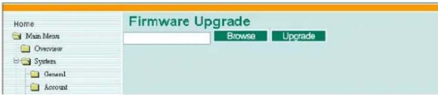
Take the following steps to upgrade the firmware:
Step 1: Press the Browse button to select the firmware file.
NOTE
For the VPort 254, the firmware file extension should be .rom.
Step 2: Click on the Upgrade button to upload the firmware to the VPort.
Step 3: The system will start to run the firmware upgrade process.
Step 4: Once Firmware Update Success.....Reboot.... is shown, please wait for few seconds for the VPort to reboot. The reboot process is finished once the STAT LED is lit continuously in green.
NOTE
Upgrading the firmware upgrade will not change the original settings.
Reset to Factory Default
From the "Reset to Factory Default" page, click on OK (as shown in the following figure) to reset the VPort to its factory default settings.
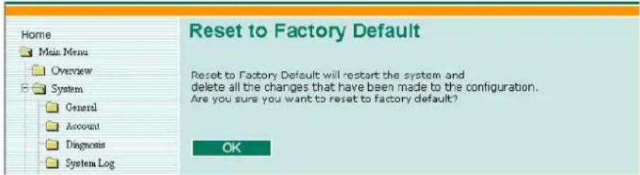
NOTE
All parameters will be reset to factory defaults when you use the Factory Default function. For this reason, if you want to keep a digital copy of the current configuration, remember to export the sys_config.ini file before using the Factory Default function.
Reboot
From the "Device Reboot" page, click OK (as shown in the following figure) to restart the VPort's system.
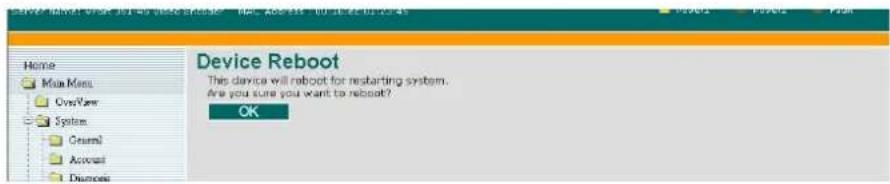
Network
General Network Settings
The General Network Settings page includes some basic but important network configurations that enable the VPort to be connected to a TCP/IP network.
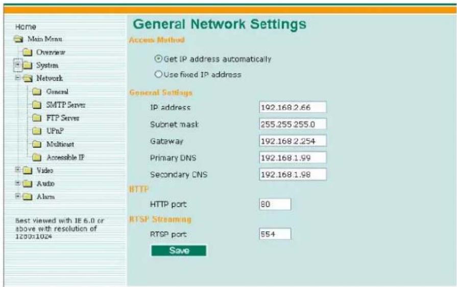
Access Method
VPort products support the DHCP protocol, which means that VPort can get its IP address from a DHCP server automatically when it is connected to a TCP/IP network. The Administrator should determine if it is more appropriate to use DHCP, or assign a fixed IP.
| Setting Description Default | ||
| Get IP address automatically | VPort gets the IP address automatically from the DHCP server. | Get IP address automatically |
| Use fixed IP address | Use the IP address assigned by the administrator. | |
NOTE
We strongly recommend that the administrator assign a fixed IP address to the VPort, since all of the functions and applications provided by the VPort are active when the VPort is connected to the network. Use DHCP to determine if the VPort's IP address may change when then network environment changes, or the IP address is occupied by other clients.
General Settings
| Setting Description Default | ||
| IP address | Variable IP assigned automatically by the DHCP server, or fixed IP assigned by the Administrator. | 192.168.127.100 |
| Subnet mask | Variable subnet mask assigned automatically by the DHCP server, or a fixed subnet mask assigned by the Administrator. | 255.255.255.0 |
| Gateway | Assigned automatically by the DHCP server, or assigned by the Administrator. | Blank |
| Primary DNS | Enter the IP address of the DNS Server used by your network. After entering the DNS Server's IP address, you can input the VPort's url (e.g., www.VPort.company.com) in your browser's address field, instead of entering the IP address. | Obtained automatically from the DHCP server, or left blank in non-DHCP environments. |
| Secondary DNS | Enter the IP address of the DNS Server used by your network. The VPort will try to locate the secondary DNS Server if the primary DNS Server fails to connect. | Obtained automatically from the DHCP server, or left blank in non-DHCP environments. |
HTTP
| Setting Description Default | ||
| HTTP Port (80, or 1024 to 65535) | HTTP port enables connecting the VPort to the web. | 80 |
RTSP Streaming
The VPort 254 supports standard RTSP (Real Time Streaming Protocol) streaming, which means that all devices and software that support RTSP can directly acquire and view the video images sent from VPort 254 without any proprietary codec or SDK installations. This makes network system integration much more convenient. For different connection types, the access name is different. For UDP and TCP streams, the access name is udpStream. For HTTP streams, the access name is moxa-cgi/udpstream_ch
| Setting Description Default | ||
| RTSP Port | An RTSP port is similar to an HTTP port, which can enable the connection of video/audio streams by RTSP. | 554 |
We use Apple QuickTime media player to illustrate RTSP streaming applications:
Step 1: Open Apple QuickTime Player and select File - Open URL in New Player.
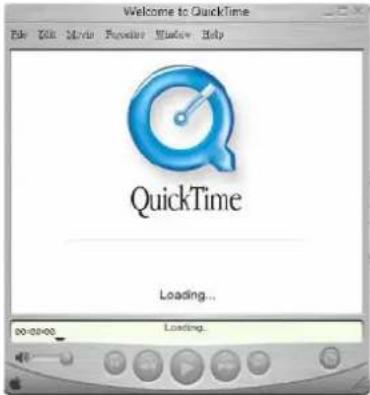
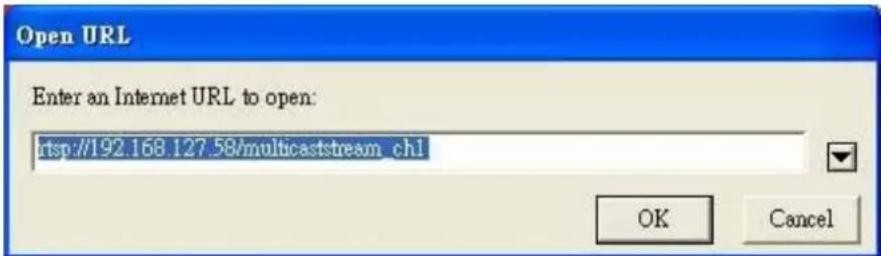
Step 2: When the following pop-up window appears, type the URL in the input box. E.g., type rtsp://
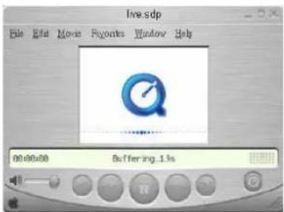
Step 3: Wait a few seconds for QuickTime Player to establish the connection.
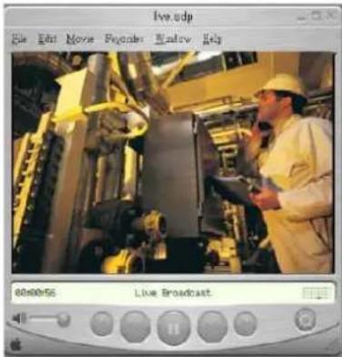
Step 4: After the connection has been established, the VPort 254's video will appear in the QuickTime Player display window.
NOTE
The video performance of the VPort 254 in other media players may not always be the same. For example, you will notice a greater delay when viewing the VPort 254's video from QuickTime player compared to viewing it directly from the VPort 254's built-in web server. In addition, viewing the VPort 254's video from Quicktime player through a router or Internet gateway could result in a broken connection.
NOTE
For the time being, the VPort 254's RTSP video/audio stream can be identified and viewed by Apple QuickTime Ver. 6.5 and above, and VLC media player. System integrators can use these 2 media players to view the VPort 254's video directly, without needing to use the VPort's SDK to create customized software.
NOTE
When using RTSP, the video stream format should be MPEG4. MJPEG does not support RTSP protocol.
SMTP Server and Email Account Settings
The VPort not only plays the role of server, but can also connect to outside servers to send alarm messages and snapshots. If the administrator has set up some applications in either system information or alarm, the VPort will send out messages or snapshots once these conditions occur.
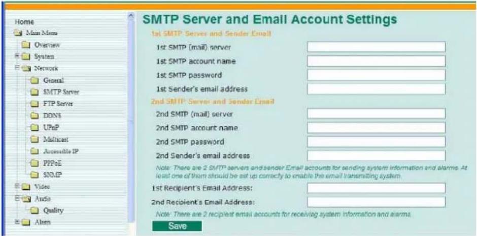
1st SMTP Server and Sender Email
| Setting Description Default | ||
| 1st SMTP (mail) server | SMTP Server's IP address or URL address. | None |
| 1st SMTP account name | For security reasons, most SMTP servers require the account name and password to be authenticated. | None |
| 1st SMTP password | None | |
| 1st Sender's email address | For security reasons, SMTP servers must see the exact sender email address. | None |
NOTE
Note that if the Sender's email address is not set, a warning message will pop up and the e-mail system will not be allowed to operate.
NOTE
The 2nd SMTP Server and Sender Email are backups that are used if the 1st SMTP Server and Sender Email fail when connecting or sending email.
Two recipient email accounts are available for receiving emails sent by the VPort. For redundancy, both addresses receive the sent messages and alarm snapshots simultaneously.
| Setting Description Default | ||
| 1st Recipient's Email Address | Email address of the 1 ^st recipient. | None |
| 2nd Recipient's Email Address | Email address of the 2 ^nd recipient. | None |
FTP Server Settings
FTP is the other method available for the VPort to send alarm messages and snapshots.
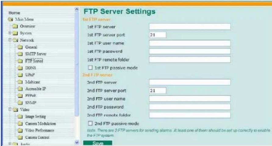
1st FTP Server
| Setting Description Default | ||
| 1st FTP server FTP server's IP address or URL address. None | ||
| 1st FTP server port None | FTP server's authentication. | |
| 1st FTP user name | None | |
| 1st FTP remote folder | FTP file storage folder on the remote FTP server. | None |
| 1st FTP passive mode | Passive transfer solution for FTP transmission through a firewall. | Disabled |
| NOTE | The 2nd FTP Server is a backup in case the 1st FTP Server fails to connect or has trouble sending files. |
| NOTE | Whenever the system reboots, a system log will be sent by email or FTP to show the login status of the VPort. The system log will be sent to the Sender email address if the SMTP server settings are correct. To send the system log via FTP, the SMTP server should be erased since the E-mail system is used by default to transmit the system log. |
| NOTE | For either e-mail or FTP, the information of the 1st server should be entered first. If the 1st server is not set, the related FTP or email will be cancelled. Note that it may take time to connect to the 2nd server after the first server fails, and it may affect some applications when adverse conditions occur too often. |
Dynamic DNS
DDNS (Dynamic Domain Name System) is a combination of DHCP, DNS, and client registration. DDNS allows administrators to alias VPort's dynamic IP address to a static hostname in any of the domains provided by the DDNS service providers listed on VPort's Network/DDNS configuration page. DDNS makes it easier to access VPort from various locations on the Internet.
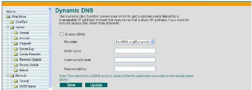
| Setting Description Default | ||
| Enable DDNS Enable | or disable DDNS function Disable | |
| Provider | Select the DDNS service providers, including DynDNS.org (Dynamic), DynDNS.org (Custom), TZO.com, and dhs.org. | None |
| Host Name The Host N | Name you use to link to the VPort. None | |
| Username/ E-mail None | The Username/E-mail and Password/Key are used to enable the service from the DDNS service provider (based on the rules of DDNS websites). | |
| Password/ Key | None | |
NOTE
Dynamic DNS is a very useful tool for accessing a VPort over the Internet, especially for xDSL connections with a non-fixed IP address (DHCP). Administrator and users can avoid the trouble of connecting with the VPort when the IP address of the VPort is not fixed, by using the unique host name in the URL to establish a connection with the VPort.
NOTE
Different DDNS service providers have different application rules. Some applications are free of charge, but most require an application fee.
Universal PnP
UPnP (Universal Plug & Play) is a networking architecture that provides compatibility among networking equipment, software, and peripherals of the 400+ vendors that are part of the Universal Plug and Play Forum. This means that they are listed in the network devices table for the operating system (such as Windows XP) supported by this function. Users can link to VPort directly by clicking on the VPort listed in the network devices table.
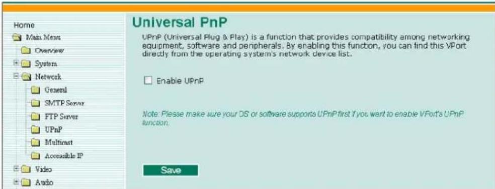
| Setting Description Default | |
| Enable UPnP Enable or disable the UPnP function. Enable |
Multicast
The VPort 254 supports the advanced Multicast network protocol IGMP, which can greatly improve the efficiency of network traffic. In this section, we explain multicasts, multicast filtering, and how multicast can be implemented on your VPort.
What is Multicast?
A multicast is a packet that is intended for “one-to-many” and “many-to-many” communication. Users explicitly request to participate in the communication by joining an end-station to a specific multicast group. If the network is set up correctly, a multicast can only be sent to an end-station or a subset of end-stations on a LAN or VLAN that belong to the relevant multicast group. Multicast group members can be distributed across multiple subnetworks. Therefore, multicast transmissions can occur within a campus LAN or over a WAN. In addition, networks that support IP multicast send only one copy of the desired information across the network. The packets are only replicated if they reach a network node that links to two or more members of the multicast network.
Transmitting packets in this way makes more efficient use of network bandwidth. A multicast packet is identified by the presence of a multicast group address in the destination address field of the packet's IP header.
Benefits of Multicast
The benefits of using IP multicast are that it:
- Enables the simultaneous delivery of information to many receivers in the most efficient, logical way.
- Reduces the load on the source (for example, a server) because it does not need to produce multiple copies of the same data.
- Makes efficient use of network bandwidth and scales well as the number of participants or collaborators expands.
• Works with other IP protocols and services, such as Quality of Service (QoS).
- There are situations where a multicast approach is more logical and efficient than a unicast approach. A typical use of multicasts is in video-conferencing, in which high volumes of traffic need to be sent to several end-stations simultaneously, but for which broadcasting that traffic to all end-stations would seriously reduce network performance. Besides, several industrial automation protocols, such as Allen-Bradley, EtherNet/IP, Siemens Profibus, and Foundation Fieldbus HSE (High Speed Ethernet), use the multicast approach. These industrial Ethernet protocols use publisher/subscriber communications models by multicasting packets that could flood a network with heavy traffic. IGMP provides the ability to prune multicast traffic so that it travels only to those end destinations that require the traffic, thus reducing the amount of traffic on the Ethernet LAN.
The network WITHOUT Multicast
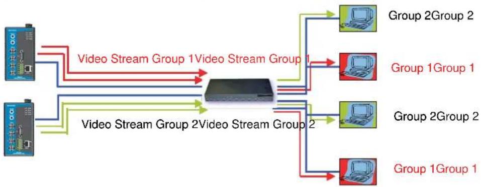
flowchart
graph LR
    A["User"] -->|Video Stream Group 1| B["Central Device"]
    C["User"] -->|Video Stream Group 2| B
    B --> D["Group 1Group 1"]
    B --> E["Group 2Group 2"]
    B --> F["Group 1Group 1"]
    B --> G["Group 2Group 2"]
    style A fill:#f9f,stroke:#333
    style C fill:#f9f,stroke:#333
    style B fill:#ccf,stroke:#333
    style D fill:#cff,stroke:#333
    style E fill:#cff,stroke:#333
    style F fill:#cff,stroke:#333
    style G fill:#cff,stroke:#333
The network WITH Multicast
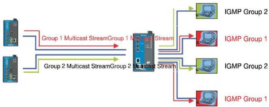
flowchart
graph TD
    A["Group 1"] -->|Group 1 Multicast StreamGroup 1 Multicast Stream| B["Central Multiplex"]
    C["Group 2"] -->|Group 2 Multicast StreamGroup 2 Multicast Stream| B
    B --> D["IGMP Group 2"]
    B --> E["IGMP Group 1"]
    B --> F["IGMP Group 2"]
    B --> G["IGMP Group 1"]
NOTE
The VPort 254 is the source that delivers the multicast video stream. To benefit from the Multicast protocol, the gateway or network switch should support the multicast filtering function (such as IGMP Snooping) so that the multicast stream is delivered correctly and precisely. To learn more about IGMP Snooping, refer to the Moxa EtherDevice™ series Industrial Ethernet Switch user's manual.
Configuring Multicast Settings
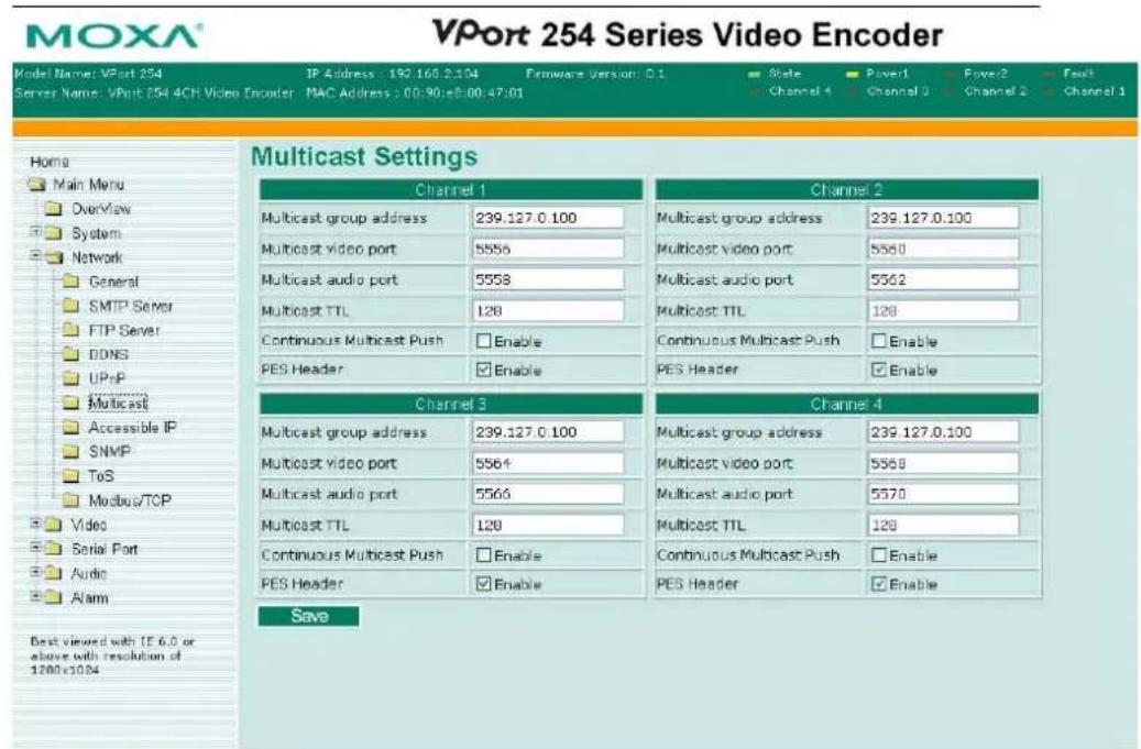
| Setting Description Default | ||
| Multicast group address | Multicast Group address for sending video stream. | 239.128.0.99 |
| Multicast video port Video port number. 5556 | ||
| Multicast audio port Audio port number. 5558 | ||
| Multicast TTL | Multicast-TTL (Time-to-live) threshold. There is a certain TTL threshold defined for each network interface or tunnel. A multicast packet's TTL must be larger than the defined TTL for that packet to be forwarded across that link. | 128 |
| Continuous Multicast Push | Enable PUSH control of the multicast video stream | Disable |
| PES Header | PES Header includes some information related to I/O status, VMD, Power, Video, and Network. This information will help users realize the VPort's status. This function is used to enable the PES Header to be attached to the multicast video stream. | Enable |
NOTE
Whenever you enable the VPort's IGMP Multicast stream, note the video/audio port number.
Accessible IP List
The VPort 254 uses an IP address-based filtering method to control access to the VPort.
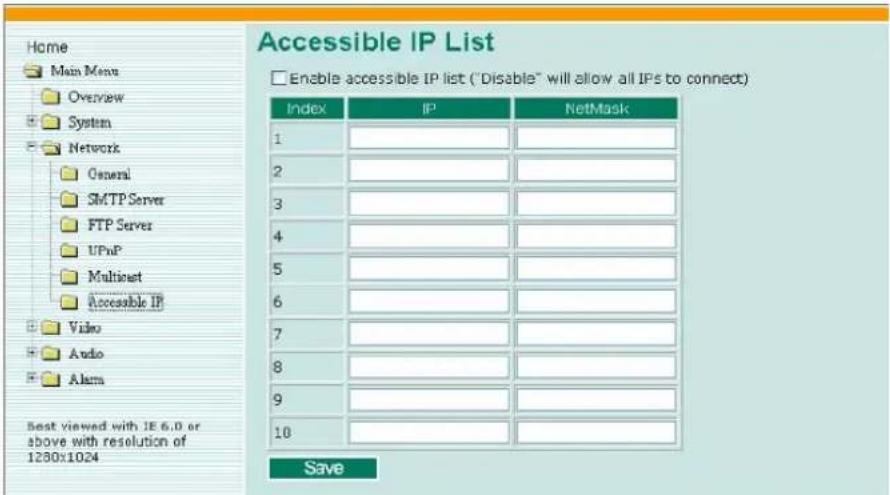
Accessible IP Settings allow you to add or remove “Legal” remote host IP addresses to prevent unauthorized access. Access to the VPort is controlled by IP address. That is, if a host’s IP address is in the accessible IP table, then the host will be allowed access to the VPort. Administrators can allow one of the following cases by setting this parameter:
- Only one host with a specific IP address can access the VPort. Enter "IP address/255.255.255.255" (e.g., 192.168.1.1/255.255.255.255)
- Hosts on a specific subnet can access the VPort.
- Enter "IP address/255.255.255.0" (e.g., "192.168.1.0/255.255.255.0")
• Any host can access the VPort. Disable this function.
Refer to the following table for more configuration examples.
| Allowable Hosts Input Formats | |
| Any host Disable | |
| 192.168.1.120 | 192.168.1.120/255.255.255.255 |
| 192.168.1.1 to 192.168.1.254 192.168.1.0/255.255.255.0 | |
| 192.168.0.1 to 192.168.255.254 192.168.0.0/255.255.0.0 | |
| 192.168.1.1 to 192.168.1.126 192.168.1.0/255.255.255.128 | |
| 192.168.1.129 to 192.168.1.254 192.168.1.128/255.255.255.128 | |
SNMP
VPort supports three SNMP protocols. The available protocols are SNMP V1, SNMP V2c, and SNMP V3. SNMP V1 and SNMP V2c use a community string match for authentication, which means that SNMP servers access all objects with read-only or read/write permissions using the community string public/private (default value). SNMP V3, which requires you to select an authentication level of MD5 or SHA, is the most secure protocol. You can also enable data encryption to enhance data security. SNMP security modes and security levels supported by VPort are shown in the following table. Select one of these options to communicate between the SNMP agent and manager.
| Protocol Version | Security Mode | Authentication Type | Data Encryption | Method |
| SNMP V1, V2c | V1, V2cRead Community | Community string | No | Use a community string match for authentication |
| V1, V2cWrite/Read Community | Community string | No | Use a community string match for authentication | |
| SNMP V3 | No-Auth | No No | Use account with admin or user to access objects | |
| MD5 or SHA | MD5 or SHA No | Provides authentication based on HMAC-MD5, or HMAC-SHA algorithms.8-character passwords are the minimum requirement for authentication. | ||
| MD5 or SHA | MD5 or SHA | Data encryption key | Provides authentication based on HMAC-MD5 or HMAC-SHA algorithms, and data encryption key.8-character passwords and a data encryption key are the minimum requirements for authentication and encryption. |
Configuring SNMP Settings
The following figures indicate which SNMP parameters can be configured. A more detailed explanation of each parameter is given below the figure.
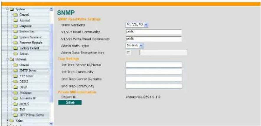
SNMP Read/ Write Settings
SNMP Versions
| Setting Description Default | ||
| V1, V2c, V3 | Select SNMP Versions V1, V2c, V3 protocol to manage the switch | V1, V2c |
| V1, V2c | Select SNMP Versions V1, V2c protocol to manage the switch | |
| V3 only | Select SNMP Versions V3 protocol only to manage the switch | |
V1, V2c Read Community
| Setting Description Default | ||
| V1, V2c Read Community | Use a community string match for authentication, which means that the SNMP agent accesses all objects with read-only permissions using the community string public. | public(max. 30 characters) |
V1, V2c Read/Write Community
| Setting Description Default | ||
| V1, V2cRead/Write Community | Use a community string match for authentication, which means that the SNMP agent accesses all objects with read-only permissions using the community string public. | public(max. 30 characters) |
For SNMP V3, there are two levels of privilege for different accounts to access the VPort. Admin privilege allows access and authorization to read and write MIB files. User privilege only allows reading the MIB file, but does not authorize writing to the file.
Root Auth. Type (For SNMP V1, V2c, V3 and V3 only)
| Setting Description Default | ||
| No-Auth | Use admin. account to access objects. No authentication | No |
| MD5-Auth | Provide authentication based on the HMAC-MD5 algorithms. 8-character passwords are the minimum requirement for authentication. | No |
| SHA- Auth | Provide authentication based on the MAC-SHA algorithms. 8-character passwords are the minimum requirement for authentication. | No |
Root Data Encryption Key (For SNMP V1, V2c, V3 and V3 only)
| Setting Description Default | ||
| Enable | 8-character data encryption key is the minimum requirement for data encryption. Maximum 30-character encryption key | No |
| Disable No data encryption No | ||
User Auth. Type (For SNMP V1, V2c, V3 and V3 only)
| Setting Description Default | ||
| No-Auth | Use account of admin or user to access objects. No authentication | No |
| MD5-Auth | Provide authentication based on the HMAC-MD5 algorithms. 8-character passwords are the minimum requirement for authentication. | No |
| SHA- Auth | Provide authentication based on the HMAC-SHA algorithms. 8-character passwords are the minimum requirement for authentication. | No |
User Data Encryption Key (For SNMP V1, V2c, V3 and V3 only)
| Setting Description Default | ||
| Enable | 8-character data encryption key is the minimum requirement for data encryption. Maximum 30-character encryption key | No |
| Disable No data encryption No | ||
Trap Settings
| Setting Description Default | ||
| Trap ServerIP/Name | Enter the IP address or name of the Trap Server used by your network. | No |
| Trap Community | Use a community string match for authentication; Maximum of 30 characters. | No |
Private MIB information
The private SNMP Object ID of the VPort is the enterprise value: 8691.8.1.5. This number cannot be changed.
QoS (ToS)
Quality of Service (QoS) provides a traffic prioritization capability to ensure that important data is delivered consistently and predictably. The VPort 351 can inspect layer 3 ToS (Type of Service) information to provide a consistent classification of the entire network. The VPort 351's ToS capability improves your industrial network's performance and determinism for mission critical applications.
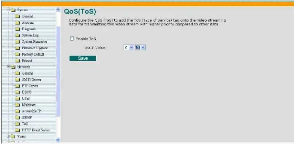
| Setting Description Factory Default | ||
| Enable ToS | Enable the ToS for transmitting the video stream with the given priority | Disable |
| DSCP Value Set | the mapping table with different ToS values 0, 0 | |
NOTE
To configure the ToS values, map to the network environment settings for QoS priority service.
Modbus/ TCP
Modbus is a serial communications protocol, which is often used to connect a supervisory computer with a remote terminal unit (RTU) in supervisory control and data acquisition (SCADA) systems. To transmit Modbus over a TCP/IP network, a standard Modbus/TCP protocol is provided. With the support of Modbus/TCP protocol, the SCADA/HMI system can directly communicate with the VPort to acquire the operation status.
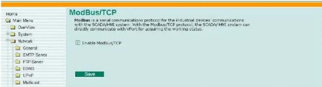
| Setting Description Factory Default | ||
| Enable Modbus/TCP | Enable the Modbus/TCP protocol Enable | |
Video
Image Settings
![Home Main Menu OverView System Network Video Image Setting Camera Modulation Video Performance Camera Control Serial Port Audio Alarm Best viewed with LE 6.0 or above with resolution of 1280x2024 Image Settings Channel Selection Channel 1 Channel 2 Channel 3 Channel 4 Image Information Description: Image Appearances Image Information: Not Shown Shown on the caption Image Tuning Save [AV-UDF] 2008/10/06 09:20:06](/content/2026/06/1281137/images/a0a53edc007431529be74487a9673fd65b438ca3205ddfc4dc6b1f640208a9e6.jpg)
Image Information Setting
| Description Default | ||
| Description (max. of 14 characters) | The customized description shown on the caption to identify this video camera. | None |
Image Appearance Setting
| Description Default | ||
| Image Information | To determine what style of image information is being shown. Includes Not Shown and Show on the Caption | Not Shown |
Image Tuning
An Image Tuning button is available for the administrator to fine tune image attributes. After clicking this button, a configuration window will pop up. You may configure Brightness, Contrast, Saturation, and Hue.
![http://192.168.2.66 - Image Tuning - Microsoft Internet E... [AV-UDPI] 2006/03/14 05:58:50 Brightness +0 Saturation +0 Contrast +0 Hue +0 Preview Restore Save Close](/content/2026/06/1281137/images/6f22dd8afeb56ad777fcb13531784f91c22f72cb3871ae52d629332b73ed6281.jpg)
Camera Modulation
The VPort 254 supports both NTSC and PAL camera modulations. The Administrator can use automatic sensing by selecting NTSC or PAL.
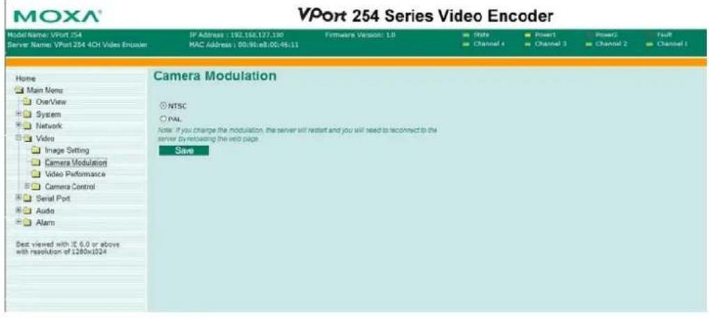
NOTE
Changing the modulation requires resetting the server to detect the camera. Please ensure that your configurations are saved before resetting the server.
Video Performance
The VPort 254 supports the MPEG4 and MJEPG compression standards. The administrator should select the video compression standard first to identify the video stream format. But before setting the video performance parameters, the administrator should decide which video performance mode is required. There are 2 video performance modes:
• Frame rate mode:
In this mode, the video performance is focused on the frame rate. The frame can be set at up to 30 frames per second for each channel, but the resolution can only be selected in CIF (NTSC: 352x240; PAL:352x288) and QVGA(NTSC: 320x240; PAL:320x288)
- Resolution Mode:
In this mode, the video performance focuses on video resolution. There are 5 resolutions to choose from
(1) Full D1(NTSC: 720x480; PAL:720x576)
(2) 4CIF (NTSC: 704x480; PAL:704x576)
(3) VGA (NTSC: 640x480; PAL:640x576)
(4) CIF (NTSC: 352x240; PAL:352x288)
(5) QVGA(NTSC: 320x240; PAL:320x288).
But the maximum frame rate for each resolution is only 7 frames per second.
For MJPEG, users can set up the Resolution, Max. Frame Rate, Video Quality in Fixed Quality, and Enable Snapshot.

For MPEG4, users can set Resolution, Max. Frame Rate, Video Quality in Fixed Bit Rate or Fixed Quality, Key Frame Interval, and Enable Snapshot.
MOXA®
VPort 254 Series Video Encoder
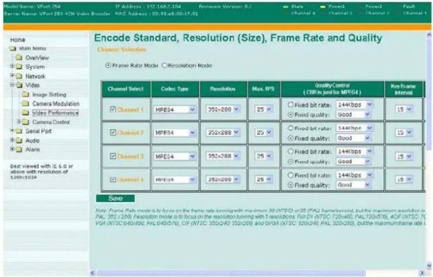
Channel Select
| Setting Description Default | ||
| Enable or disable the video channel | The administrator can enable or disable the video channel to show or not show the video image. | enable |
Codec Type
| Setting Description Default | ||
| MJPEG or MPEG4 Select the MJPEG or MPEG4 codec MPEG4 | ||
Resolution
The VPort 254 supports 5 different resolutions: Full D1, 4CIF, VGA, CIF, and QVGA.
| Setting Description Default | ||
| Select the image size | 5 image resolutions (size) are provided. The administrator can choose each option with NTSC or PAL modulation. | 352 x 240 in NTSC or 352 x 288 in PAL |
| Resolution NTSC PAL | ||
| Full D1 | 720 x 480 | 720 x 576 |
| 4CIF | 704 x 480 | 704 x 576 |
| VGA | 640 x 480 | 640 x 576 |
| CIF | 352 x 240 | 352 x 288 |
| QVGA | 320 x 240 | 320 x 288 |
Max. FPS (Frame per second)
| Setting Description Default | ||
| Maximum frame rate | The maximum frame rate is different to accommodate different modulations of video input. Administrators can also set up the maximum frame rate to optimize the bandwidth’s occupation. | Frame Mode:30 for NTSC, 25 for PALResolution Mode:7 for NTSC or 6 for PAL |
| Key frame interval(Only for MPEG4) | Administrators can set up the key frame interval to determine the video quality. | 15 |
| NOTE | Frame rate (frames per second) is determined by the resolution, image data size (bit rate), and transmission traffic status. The Administrator and users can check the frame rate status in the FPS Status on VPort’s web homepage. |
| NOTE | A large “Key frame interval” can reduce the bit rate, but will cause the image to be corrupted longer if there is packet loss during transmission. |
Video Quality Control
Video Quality Control is used to optimize the bandwidth of the MPEG4 video stream. There are 2 modes for video quality control.
| Setting Description Default | ||
| Fixed bit rate(Only for MPEG4) | The administrator can fix the bandwidth to tune the video quality and FPS (frames per second) to the optimum combination.Different resolutions have different bandwidth parameters. The VPort will tune the video performance according to the bandwidth. A higher bandwidth means better quality and higher FPS. | 144 Kbps in CIF resolution |
| Fixed Quality | The administrator can set the image quality to one of 5 standards:Medium, Standard, Good, Detailed, or Excellent. The VPort will tune the bandwidth and FPS automatically to the optimum combination. | Good |
| NOTE | The image quality, FPS, and bandwidth are influenced significantly by network throughput, system network bandwidth management, applications the VPort runs (such as VMD), how complicated the image is, and the performance of your PC or notebook when displaying images. The administrator should take into consideration all of these variations when designing the video over IP system, and when specifying the requirements for the video system. |
Key Frame Interval
With MPEG4, the key frame plays an important role in deciding the video quality. The key frame interval indicates how many frames are required for the VPort to get a key frame. A smaller “key frame interval” means better video quality, but the bandwidth will be increased since the key frame image size is larger than other frames.
| Setting Description Default | ||
| Key frame interval(Only for MPEG4) | Administrators can set up the key frame interval to determine the video quality. | 15 |
| NOTE | A large “Key frame interval” can reduce the bit rate, but will cause the image to be corrupted longer if there is packet loss during transmission. |
Enable Snapshot
| Setting Description Default | ||
| Enable or disable the snapshot image | To get the snapshot image, the VPort needs to capture one image frame from the total frames, which may decrease the total FPS of the video stream. The administrator can decide if this snapshot function should be used. | disable |
Camera Control
The VPort supports PTZ (PAN/TILT/ZOOM) motorized camera control via an RS-232, RS-422, or RS-485 PTZ/ COM port. Before setting up camera control, the administrator should first connect the PTZ camera to the VPort. (Please refer to Chapter 2 for the PTZ port's wiring specifications.)
![PTZ (Motorized) Camera Control Interface Mode Select the control port: COM Port Camera Selection Camera ID 1 [AV-UDP] 2008/10/06 10:21:40 PTZ Camera Control Position Alias Edit/Remove Preset Position 01 Delete Go To Select... Last Position Stop Window Zoom AUTO POCUS AUTO IEE TIM Speed 1 Pan Speed 1 Zoom Speed 1](/content/2026/06/1281137/images/91d78d398716ed88fe8a4176081071175cd9d344983b64d6780fbc18730e10c6.jpg)
Interface mode
| Setting Description Default | ||
| Select the Control port | There are 2 serial ports on VPort 254. One is PTZ port, the other is COM port. The administrator should decide which serial port is used for connecting this camera's PTZ control | COM port |
Camera ID
| Setting Description Default | ||
| Camera ID | Each PTZ camera has an ID to identify which PTZ camera is in the multi-drop connection. To connect to the PTZ camera, the VPort should first identify its ID. | 1 |
Setting Up a Preset Position
Administrators can use the Preset Position function to set up the behavior of the PTZ camera in advance, and then users with camera control privilege can move the camera's lens to a preset position without the need to control the pan, tilt, and zoom buttons on the PTZ control panel.
| Setting Description | Default | |
| Position Alias Customized name of the preset position blank | ||
| Preset Position | 25 preset positions are available for the VPort. | 01 |
| Go to | The administrator can use “Go to” to select or test the preset position before the save. | Select |
| Last Position | This column shows the current preset position of this PTZ camera. | blank |
| Set Home | This button can decide the Home position of PTZ control | |
| ZOOMAuto FocusAuto IRIS | These buttons are to fine tune the PTZ camera’s lens positions. | |
| TILT SPEEDPAN SPEEDZOOM SPEED | These items are used to change the speed of TILT, PAN and ZOOM. | 1 |
Serial Port
The VPort 254 has 2 serial ports. One is the PTZ port and the other is the COM port. Both ports can be set for RS-232, RS-422, or RS-485. Refer to Quick Installation Guide or Chapter 2 for the connector type and pin assignment.
PTZ port
This PTZ port is used to control a PTZ camera.
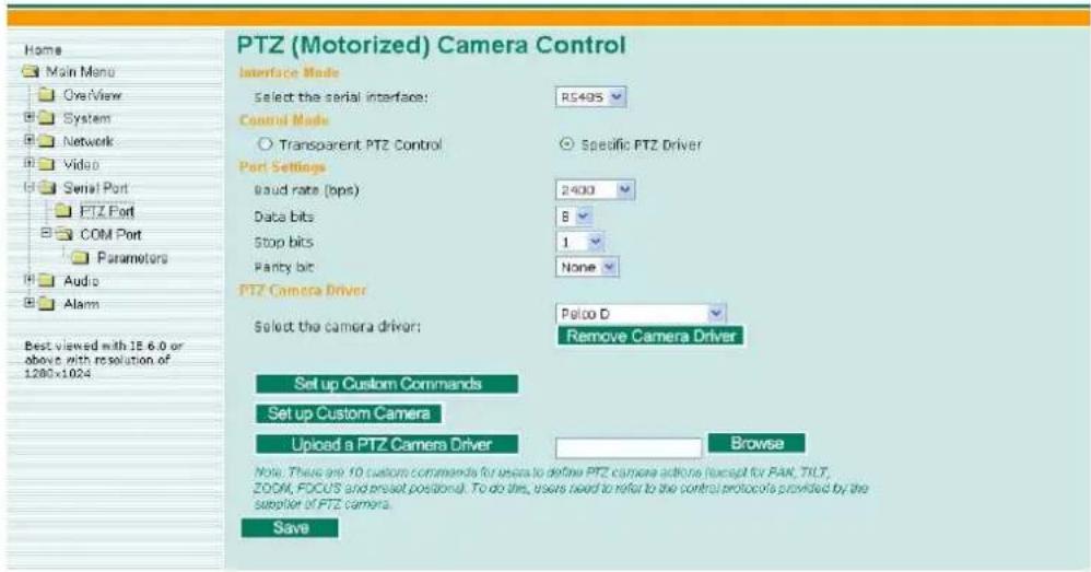
Interface mode
| Setting Description Default | ||
| Select the serial interface | The PTZ port supports 3 serial interfaces, although only one interface can be used at a time. Depending on the interface used by the attached device, administrators must set theInterface mode to either RS-232, RS-422, or RS485. | RS485 |
Control mode
The VPort supports 2 PTZ control modes: "Transparent PTZ" control and "PTZ driver."
• Transparent PTZ Control:
Select Transparent PTZ Control to control the PTZ camera with a legacy PTZ control panel or joystick connected to the CCTV system. The application is illustrated in the following figures.
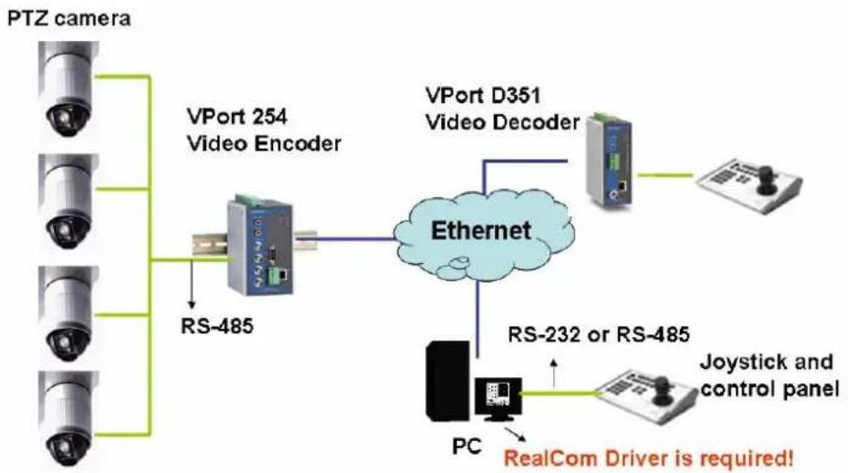
flowchart
graph TD
    A["PTZ camera"] --> B["VPort 254 Video Encoder"]
    B --> C["RS-485"]
    C --> D["Ethernet"]
    D --> E["VPort D351 Video Decoder"]
    E --> F["Joystick and control panel"]
    D --> G["PC"]
    G --> H["RealCom Driver is required!"]
In Transparent PTZ Control mode, the serial data from the legacy PTZ control panel or joystick will be transformed into IP packets for transmission over a TCP/IP network, and once the VPort video encoder receives these IP packets, the PTZ control commands will be transformed back to serial data format for controlling the PTZ camera's action. You do not need to install a PTZ driver to control the PTZ camera's action, which means that a large variety of different PTZ cameras can be used with the VPort video encoders and their supported PTZ control panel or joystick.
NOTE
The legacy PTZ control panel or joystick should be connected to the VPort's PTZ port or the COM port of a PC. But, when it is connected to a PC's COM port, you will need to install a real COM driver on the PC and map the COM ports. For detailed information, refer to the VPort SDK PLUS-ActiveX Control SDK for the Real COM driver and COM port mapping function sample codes. You can download this SDK from Moxa's website (www.moxa.com).
- Specific PTZ Driver:
Usually, a PTZ driver is required to control a PTZ camera over a TCP/IP network. This is because each PTZ camera supplier has their own proprietary PTZ control protocol. VPort video encoders support all popular PTZ drivers for controlling PTZ cameras.
| Setting Description Default | ||
| Control Mode | Select the PTZ control mode in Transparent PTZ Control or PTZ Driver | PTZ driver |
The configurations described below are only available in PTZ Driver mode.
Port Settings
| Setting Description Default | ||
| Baud rate (bps) | The baud rate specified by the PTZ camera's serial communication specs. | 2400 |
| Data bits 8 | The parameters used to define the serial communication. | |
| Stop bits 1 | ||
| Parity bits | None | |
PTZ Camera Drivers
VPort products come with PTZ camera drivers for some of the popular PTZ cameras.
Administrators can select the correct PTZ driver in Select the camera driver menu. If the attached PTZ camera is not supported by the VPort, administrators can use the Custom Camera function to enter the proprietary commands for pan, tilt, zoom, and focus control.
| Setting Description Default | ||
| Select the camera driver | Use the built-in PTZ drivers, including1. Custom Camera2. Pelco D3. Pelco P4. Dynacolor DynaDome | Pelco D |
Set Up Custom Commands
VPort products provide 10 custom commands in addition to the general pan, tilt, zoom, and preset functions, which are also shown on the PTZ Control Panel. Administrators can click on Setup Custom Commands to configure the commands, and refer to the manual enclosed with the attached PTZ camera to set up frequently-used functions. The Command should be entered in ASCII format. The VPort will translate the commands into binary code and then send the data out through the serial port. For instance, the text string 81 01ABCDEF will be translated into five bytes of hexadecimal: 81, 01, AB, CD, and EF. The maximum length of a command string is 60, which is equivalent to 30 hexadecimal bytes. The Display string is for the text on the command buttons and should be less than 8 characters. If Custom Camera is selected, there will be more commands for PTZF that relate to custom camera.
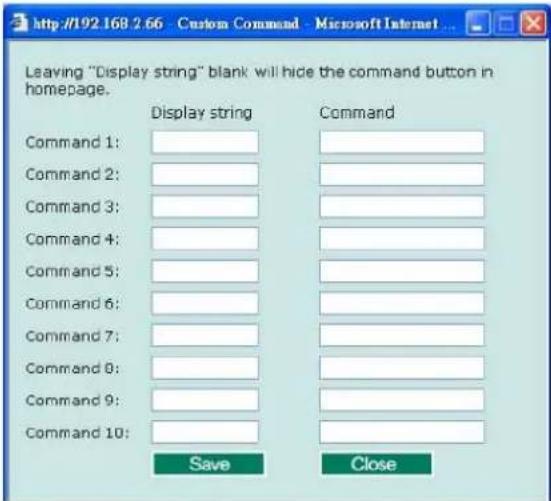
Setting Up Custom Camera
If the PTZ camera's driver is not in the list, the administrator can select the custom camera from the Select Camera driver menu to program the PTZ camera with ASCII code. A custom camera window will pop up when the Setup Custom Camera button is clicked. Input the ASCII code into this window. Port Settings (Data bits, Stop bits, and Parity bits) are for the serial communication parameters and Control Settings are for programming the TILT (Move Up, Move Down), PAN (Move Left, Move right), HOME, ZOOM (Zoom in, Zoom out) and FOCUS (Focus near, Focus Far) actions.
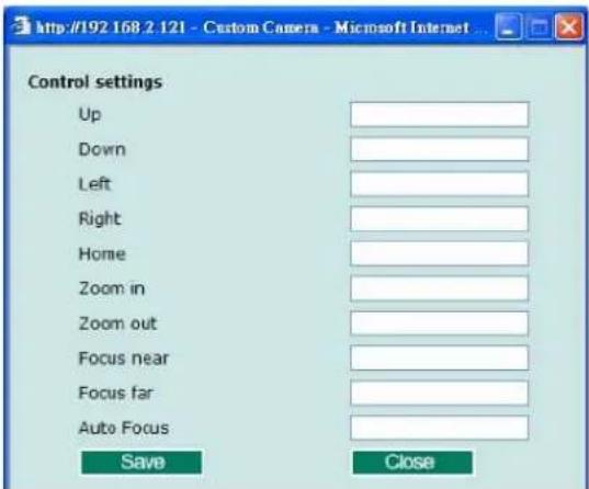
NOTE
The control protocols are available from the PTZ camera's supplier. You will need to get the protocols from the supplier before programming the PTZ camera.
Uploading a PTZ Camera Driver
In addition to the PTZ camera drivers and custom camera functions supported by the VPort, an alternative user-friendly Upload a PTZ Camera Driver function is available for implementing the PTZ camera control. Moxa will release new PTZ camera drivers to Moxa's website as they become available. Administrators can click on Browse to upload the new PTZ camera drivers to the VPort. In addition, the administrator can also remove the PTZ driver by selecting the PTZ driver and clicking the Remove Camera Driver button.
COM port
The COM port has 2 uses: PTZ control and serial device control.
Interface mode
| Setting Description Default | ||
| Select the serial interface | The COM port supports 3 serial interfaces, although only one interface can be used at a time. Depending on the interface used by the attached device, administrators must set the Interface mode to either RS-232, RS-422, or RS-485. | RS485 |
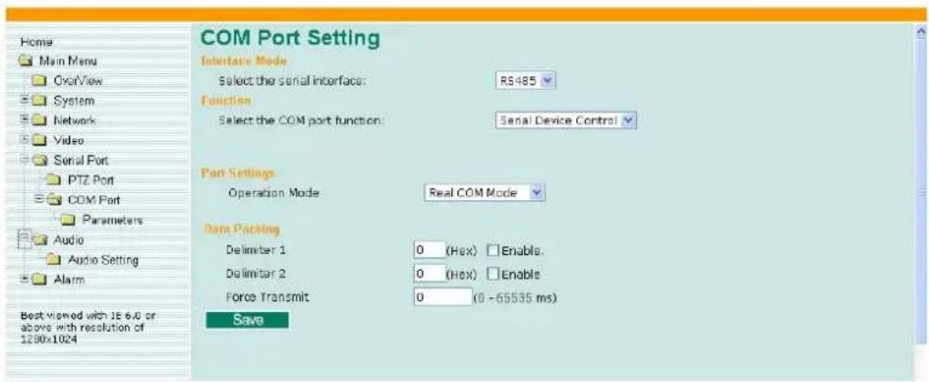
Function
This COM port supports 2 functions: Serial Device Control and PTZ Camera Control. Each function has different configurations.
- Serial Device Control: The VPort supports 3 operation modes when using serial device control mode over a TCP/IP network: Real COM Mode, TCP Server Mode, and TCP Client Mode.
- Real COM Mode: The VPort is equipped with COM drivers that work with Windows Vista/XP/2000 systems. The driver establishes a transparent connection between the host and serial device by mapping the IP:Port of the VPort's COM port to a local COM port on the host computer. The important point is that Real COM Mode allows users to continue using RS-232/422/485 serial communication software that was written for pure serial communication applications. The driver intercepts data sent to the host's COM port, packs it into a TCP/IP packet, and then redirects it through the host's Ethernet card. At the other end of the connection, the VPort's COM port accepts the Ethernet frame, unpacks the TCP/IP packet, and then transparently sends it to the appropriate serial device attached to the VPort's COM port.
- TCP Server Mode: In TCP Server mode, the VPort provides a unique IP:Port address on a TCP/IP network. The VPort waits passively to be contacted by the host computer, allowing the host computer to establish a connection with and get data from the serial device.
- TCP Client Mode: In TCP Client mode, the VPort can actively establish a TCP connection to a pre-defined host computer when serial data arrives. After the data has been transferred, the VPort can automatically disconnect from the host computer by using the TCP alive check time or Inactivity timeout settings.
NOTE
These VPort COM port operation modes only support one connection at the same time.
NOTE
For more information on serial-to-Ethernet communications, refer to Moxa's NPort Device Server products.
- PTZ Camera Control: This PTZ Camera Control function is the same as the PTZ port. Refer to the introduction to the configuration of the PTZ Port.
Function
| Setting Description Default | ||
| Select the COM port function | Select the application purpose of this COM port: Serial Device Control or PTZ Camera Control | Serial Device Control |
Port Settings (only available in Serial Device Control)
| Setting Description | Default | |
| Operation Mode | Select the serial device control operation modes via the TCP/IP network: Real COM Mode, TCP Server Mode, TCP Client Mode | Real COM Mode |
| Inactivity time(Only available in TCP Server Mode,TCP Client Mode) | The VPort automatically closes the TCP connection if there is no serial data activity for the given time (0 to 65535 milliseconds). After the connection is closed, the VPort starts listening for another host’s TCP connection. | 0 |
Data Packing (only available in Serial Device Control)
| Setting Description | Default | |
| Delimiter 1Delimiter 2 | Once the VPort receives both delimiters through its serial port, it immediately packs all data currently in its buffer and sends it to the VPort's Ethernet port.The setting value of the delimiter is from 00 to FF. In addition, both delimiters can be enabled or disabled. | Disable |
| Force Transmit | This parameter defines the time interval during which the VPort fetches the serial data from its internal buffer. If data is incoming through the serial port, the VPort stores the data in the internal buffer. The VPort transmits data stored in the buffer via TCP/IP, but only if the internal buffer is full or if the force transmit time interval reaches the time specified under Force Transmit timeout.The time interval can be set from 0 to 65535 milliseconds. Set the time interval to 0 to disable force transmit timeout. | 0 |
NOTE
Delimiter 2 is optional. If left blank, then Delimiter 1 alone trips clearing of the buffer. If the size of the serial data received is greater than 1 KB, the VPort will automatically pack the data and send it to the Ethernet. However, to use the delimiter function, you must at least enable Delimiter 1. If Delimiter 1 is left blank and Delimiter 2 is enabled, the delimiter function will not work properly.
TCP Server Mode (only available in Serial Device Control and TCP Server Mode)
| Setting Description Default | ||
| Local TCP port | The TCP port that the VPort uses to listen to connections, and that other devices must use to contact VPort. The settings should be from 1 to 65535. | 4001 |
TCP Client Mode (only available in Serial Device Control and TCP Client Mode)
| Setting Description Default | ||
| Destination IP address | Allows the VPort to connect actively to the remote host whose address is set by this parameter. | blank |
| Designated Local port | TCP port number for the connection. It can also be enabled or disabled. | disable |
| TCP Connect On | Startup: A TCP connection will be established on startup, and will remain active indefinitely.Any Character: A TCP connection will be established when any character is received from the serial interface, and will remain active indefinitely. | Startup |
NOTE
To avoid influencing the video performance, it is strongly recommended that the VPort's COM port should be used for simple serial control and data transmission, such as a card reader.
Parameters
Some COM port parameters need to be configured.
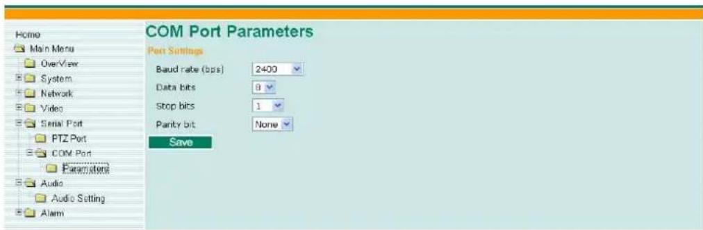
Port Settings
| Setting Description | ||
| Baud rate (bps) | The baud rate specified by the PTZ camera's serial communication specs. | 2400 |
| Data bits 8 | The parameters used to define the serial communication. | |
| Stop bits 1 | ||
| Parity bits | None | |
Audio
Audio Source
The VPort 254 supports real-time and synchronous video/audio transmission. Administrators need to select the correct input type of audio source to avoid audio input distortion.
| Setting Description | Default | |
| Audio Source | For the audio connection, MIC-in (microphone) and Line-in (voice amplifier) are included for convenience. | Line in |
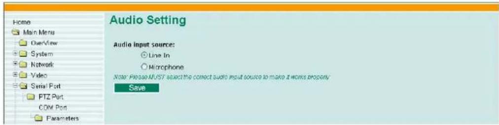
Alarm
System Alarm
In addition to the LED indicators, three kinds of system alarm are provided by the VPort 254 for notifying the system operation administrator.
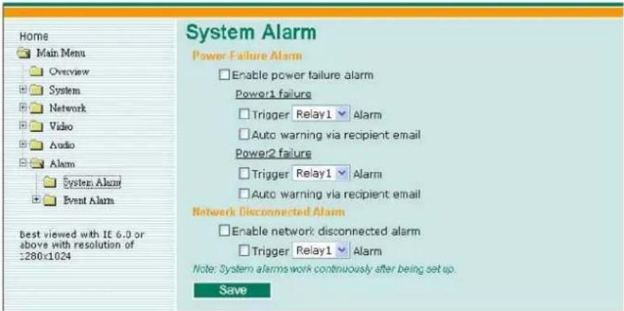
| Alarm Type Triggered Condition Triggered Action | ||
| Power Failure | 1. Power 1 failure2. Power 2 failure | 1. Relay2. Email |
| Network Disconnected | Network disconnected Relay | |
Power Failure Alarm
| Setting Description Default | ||
| Enable power failure alarm | Enable or disable power failure alarm. Disable | |
Power 1 Failure/Power 2 Failure
| Setting Description Default | ||
| Trigger Relay alarm | Enable or disable the action of triggering Relay 1 or Relay 2 alarms. | Disable |
| Auto warning via recipient email | Enable or disable the action to send a warning message by recipient's email, which is set up on the Network/ SMTP Server configuration page. | Disable |
Network Disconnected Alarm
| Setting Description Default | ||
| Enable network disconnected alarm | Enable or disable network disconnected alarm. | Disable |
| Trigger Relay alarm | Enable or disable the action of triggering Relay 1 or Relay 2 alarms. | Disable |
NOTE
Since several alarms can be set up to trigger the VPort's relays, the administrator should configure these alarms carefully in case a relay message is read incorrectly.
Event Alarm
Four kinds of event alarm are provided by the VPort 254 for building an intelligent video surveillance system.
| Alarm Type Triggered Condition Triggered Action | ||
| Video Motion Detection (VMD) | 1. VMD 12. VMD 23. VMD 3 | 1. Relay2. Email3. FTP4. HTTP Event Server |
| Digital Inputs | 1. DI 12. DI 2 | 1. Relay2. Email3. FTP4. HTTP Event Server |
| Video Loss | Video signal is lost | 1. Relay2. Email3. HTTP Event Server |
| Sequential Snapshot | Enable sequential snapshot | 1. Email2. FTP |
NOTE
Event alarms for VMD, Digital Inputs, and Video loss are supported firmware version V2.0 and later.
Basic
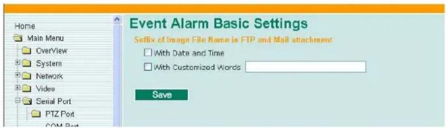
Suffix of Image File Name in FTP and Mail attachment
The snapshot images can be sent either by email or FTP. Administrators can add a suffix to the filename of each JPEG snapshot image to make it easier to identify the files when using FTP to download the snapshots.
| Setting Description Default | ||
| With Date and Time | Enable or disable the function of adding the date and time to the filename. | Disable |
| With Customized words | Enable or disable the function of adding some additional text to the filename to identify the snapshot image. | Disable |
Alarm/Event Alarm/Sequential Snapshot
With this feature, the VPort can upload snapshots periodically to an external E-mail or FTP server as a live video source. Use the Send sequential snapshot image every seconds option to set the time interval. The interval can be set to any number from 1 second to 9999 seconds.
| Setting Description Default | ||
| Enable Sequential Snapshots | Enable or disable the Sequential Snapshots. | Disable |
| Send sequential snapshot image every seconds | Set the time interval of each snapshot image. | 30 seconds (from 1 second to 30 seconds) |
| Send Snapshot image via E-mail | Choose how to send the snapshot images. | Send Snapshot image via Email |
| Send Snapshot image via FTP | ||
![Home Main Menu Overview System Network Video Serial Port PTZ Port COM Port Parameters Audio Audio Setting Alarm System Event Alarm Basic Sequential Snap Best viewed with 1E 6.0 or Sequential Snapshots Channel Select Send Interval(Sec.) Send Method Channel 1 Send sequential snapshot image every 30 [1~30] second(s) Send snapshot image via E-mail Send snapshot image via FTP Channel 2 Send sequential snapshot image every 30 [1~30] second(s) Send snapshot image via E-mail Send snapshot image via FTP Channel 3 Send sequential snapshot image every 30 [1~30] second(s) Send snapshot image via E-mail Send snapshot image via FTP Channel 4 Send sequential snapshot image every 30 [1~30] second(s) Send snapshot image via E-mail Send snapshot image via FTP Save](/content/2026/06/1281137/images/a53ece79498356c751589af24893690288947f395db604b86f8b4989244aac8a.jpg)
Q: What if I forget my password?
A: Every access to the video encoder needs authentication, unless the admin password is set up as blank. If you are one of the managed users, you will need to ask the administrator for the password. If you are the administrator, there is no way to recover the admin password. The only way to regain access to video encoder is to utilize the RESET button on the top panel to restore the factory settings (see Chapter 1 for details).
Q: Why can't I see video from the video encoder after it has been authenticated?
A: There are many possible scenarios:
- If you have just installed the video encoder and are unable to see the video, check the video modulation on the System Configuration\Video\Camera Modulation page.
- If the video encoder is installed correctly and you are accessing the video encoder for the first time using Internet Explorer, adjust the security level of Internet Explorer to allow installation of plug-ins.
- If the problem still exists, the number of users accessing the video encoder at the same time may exceed the maximum that the system allows.
Q: What is the plug-in for?
A: The plug-in provided by video encoder is used to display motion pictures. The plug-in is needed because Internet Explorer does not support streaming technology. If your system does not allow installation of plug-in software, the security level of the web browser may need to be lowered. It is recommended that you consult the network supervisor in your office before adjusting the security level.
Q: Why is the timestamp different from the system time of my PC or notebook?
A: The timestamp is based on the system time of the video encoder. It is maintained by an internal real-time clock, and automatically synchronizes with the time server if the video encoder is connected to the Internet and the function is enabled. Differences of several hours may result from the time zone setting.
Q: Why doesn't the image refresh regularly?
A: This may be due to the time it takes to store recorded video and snapshots into memory, or the time it takes to send the images to the SMTP and FTP server when events occur.
Q: How many users are allowed to access the video encoder at the same time?
A: Basically, there is no limitation. However the video quality also depends on the network. To achieve the best effect, the VPort 254 video encoder will allow 8 video streams for udp/tcp/http connections. We recommend using an additional web server that retrieves images from the video encoder periodically if you need to host a large number of users.
Q: What is the video encoder's video rate?
A: The MPEG4 codec can process 30 frames per second internally. However the total performance is subject to many coefficients, as listed below:
- Network throughput.
- Bandwidth share.
- Number of users.
- More complicated objects result in larger image files.
- The level of your PC or notebook that is responsible for displaying images.
In general, the transfer rate for a general local network environment can achieve over 800 kilobytes per second and approximately 10 to 20 pictures of a normal environment per second.
Q: How can I keep the video encoder as private as possible?
A: The video encoder is designed for surveillance purposes and has many flexible interfaces. The user authentication and special confirmation when installing can keep the video encoder from unauthorized access. You may also change the HTTP port to a non-public number. Check the system log to examine any abnormal activities and trace the origins.
Q: I have a PTZ camera that is not on the support list. How can I control it?
A: The video encoder provides a custom camera command interface to control cameras that are not supported. The details are described in this manual. Be sure that the PTZ port settings are applied to the camera specifications. The general PTZ command is composed of one start command and one stop command. When editing both commands in the edit box of the configuration page, use comma(s) to separate commands. Each comma represents 200 milliseconds. In addition, the VPort has a PTZ driver upload function. Users can also seek help from Moxa to create a new PTZ driver.
Q: How fast will the video encoder check the status of digital inputs?
A: The video encoder will check the input status in less than half a second.
Q: Why can't I access the video encoder when I set up some options in the application?
A: When the video encoder is triggered by events, video and snapshots will take more time to write to memory. If the events occur too often, the system will always be busy storing video and images. We recommend using sequential mode or an external recorder program to record motion pictures if the event is frequent. If you prefer to retrieve images by FTP, the value could be smaller since an FTP server responds more quickly than a web server. Once the system is too busy to configure, use the restore factory default and reset button to save the system.
Q: The image is not clear enough. Is anything broken?
A: The lens can be focused by rotating the outer ring. Rotate it clockwise or counter-clockwise to focus near or far.
Since the COM port settings can be adjusted to other than the default settings, check the correct default settings for the attached camera.
| Camera model | Baud rate | Data bits | Stop | bit | Parity | bit |
| Pelco P, D protocol | 2400 | 8 1 None | ||||
| DynaDome/SmartDome | 9600 | 8 | 1 | None | ||
The hour offsets for different time zones are shown below. You will need this information when setting the time zone in automatic date/time synchronization. GMT stands for Greenwich Mean Time, which is the global time that all time zones are measured from.
(GMT-12:00) International Date Line West
(GMT-11:00) Midway Island, Samoa
(GMT-10:00) Hawaii
(GMT-09:00) Alaska
(GMT-08:00) Pacific Time (US & Canada), Tijuana
(GMT-07:00) Arizona
(GMT-07:00) Chihuahua, La Paz, Mazatlan
(GMT-07:00) Mountain Time (US & Canada)
(GMT-06:00) Central America
(GMT-06:00) Central Time (US & Canada)
(GMT-06:00) Guadalajara, Mexico City, Monterrey
(GMT-06:00) Saskatchewan
(GMT-05:00) Bogota, Lima, Quito
(GMT-05:00) Eastern Time (US & Canada)
(GMT-05:00) Indiana (East)
(GMT-04:00) Atlantic Time (Canada)
(GMT-04:00) Caracas, La Paz
(GMT-04:00) Santiago
(GMT-03:30) Newfoundland
(GMT-03:00) Brasilia
(GMT-03:00) Buenos Aires, Georgetown
(GMT-03:00) Greenland
(GMT-02:00) Mid-Atlantic
(GMT-01:00) Azores
(GMT-01:00) Cape Verde Is.
(GMT) Casablanca, Monrovia
(GMT) Greenwich Mean Time: Dublin, Edinburgh, Lisbon, London
(GMT+01:00) Amsterdam, Berlin, Bern, Stockholm, Vienna
(GMT+01:00) Belgrade, Bratislava, Budapest, Ljubljana, Prague (GMT+01 :00) Brussels, Copenhagen, Madrid, Paris
(GMT+01:00) Sarajevo, Skopje, Warsaw, Zagreb
(GMT+01:00) West Central Africa
(GMT+02:00) Athens, Istanbul, Minsk
(GMT+02:00) Bucharest
(GMT+02:00) Cairo
(GMT+02:00) Harare, Pretoria
(GMT+02:00) Helsinki, Kyiv, Riga, Sofia, Tallinn, Vilnius
(GMT+02:00) Jerusalem
(GMT+03:00) Baghdad
(GMT+03:00) Kuwait, Riyadh
(GMT+03:00) Moscow, St. Petersburg, Volgograd
(GMT+03:00) Nairobi
(GMT+03:30) Tehran
(GMT+04:00) Abu Dhabi, Muscat (GMT+04:00) Baku, Tbilisi, Yerevan (GMT+04:30) Kabul
(GMT+05:00) Ekaterinburg
(GMT+05:00) Islamabad, Karachi, Tashkent (GMT+05:30) Chennai, Kolkata, Mumbai, New Delhi
(GMT+05:45) Kathmandu
(GMT+06:00) Almaty, Novosibirsk (GMT+06:00) Astana, Dhaka
(GMT+06:00) Sri Jayawardenepura (GMT+06:30) Rangoon
(GMT+07:00) Bangkok, Hanoi, Jakarta (GMT+07:00) Krasnoyarsk
(GMT+08:00) Beijing, Chongqing, Hongkong, Urumqi
(GMT+08:00) Taipei
(GMT+08:00) Irkutsk, Ulaan Bataar (GMT+08:00) Kuala Lumpur, Singapore (GMT+08:00) Perth
(GMT+09:00) Osaka, Sapporo, Tokyo (GMT+09:00) Seoul
(GMT+09:00) Yakutsk
(GMT+09:30) Adelaide
(GMT+09:30) Darwin
(GMT+10:00) Brisbane
(GMT+10:00) Canberra, Melbourne, Sydney
(GMT+10:00) Guam, Port Moresby (GMT+10:00) Hobart
(GMT+10:00) Vladivostok
(GMT+11:00) Magadan, Solomon Is., New Caledonia
(GMT+12:00) Auckland, Wellington (GMT+ 12:00) Fiji, Kamchatka, Marshall Is.
(GMT+13:00) Nuku'alofa
Video
Video Compression MPEG4, MJPEG
Video Inputs 4, BNC Connector (1 Vpp, 75 ohms)
NTSC/PAL Auto-sensing or Manual
Video Resolution and FPS (frames per second):
| NTSC | PAL | |||
| Size Max. FPS Size | Max. FPS | |||
| QVGA 320 x 240 30 320 x 288 25 | ||||
| CIF 352 x 240 30 352 x 288 25 | ||||
| VGA | 640 x 480 | 7 640 | x 480 | 7 |
| 4CIF* | 704 x 480 | 7 704 | x 576 | 7 |
| Full D1 | 720 x 480 | 7 720 | x 576 | 7 |
Video Viewing
Adjustable image size and quality Timestamp and text overlay
Audio
Audio Input 1 Line-in or MIC-in, RCA connector
Audio Output 1 Line-out, RCA connector
Network
Protocols TCP, UDP, HTTP, SMTP, FTP, Telnet, NTP, DNS, DHCP, UPnP, RTP, RTSP, ICMP, IGMPv3, QoS (ToS), SNMP (V1/V2c/V3), DDNS, Modbus/TCP
Ethernet 1 10/100BaseT(X) auto negotiation speed RJ45 port, or 1 100BaseFX fiber port (SC connector)
Optical Fiber:
| 100BaseFX | ||
| Multi Mode Single | Mode | |
| Wavelength 1300 nm 1310 | nm | |
| Max. TX -10 dBm 0 dBm | ||
| Min. TX -20 dBm -5 dBm | ||
| RX Sensitivity -32 dBm -34 dBm | ||
| Link Budget 12 dB 29 dB | ||
| Typical Distance 5 km | ^a 4 km^b | 40 km^c |
| Saturation -6 dBm -3 dBm | ||
a. 50/125μm, 800 MHz*km fiber optic cable
b. 62.5/125μm, 500 MHz*km fiber optic cable
c. 9/125μm, 3.5 PS/(nm*km) fiber optic cable
Serial Port
| COM port | 1 RS-232 or RS-422/485 port, DB9 male connector, 115.2 Kbps max. baudrae, with 15 KV ESD protection |
PTZ port 1 port, RS-232 or RS-422/485 terminal block connector, 115.2
Kbps max. baudrate, with 15 KV ESD protection
Console port 1 RS-232 RJ45 port
GPIO
| Digital Input | 4, max. 8 mA |
| “High”: +13V to +30V | |
| “Low”: -30V to +3V | |
| Relay Output | 2 (max. 24 VDC @ 1A) |
LED Indicators
| STAT | Indicates if the system booted properly |
| PWR1 | Power 1 |
| PWR2 | Power 2 |
| FAULT | Can be configured for system alarm, power failure, video loss, or network down |
| V1, V2, V3, V4 | Video input signal active |
Power
| Inputs | Two 12/24 VDC or 24 VAC for redundancy |
| Consumption | Approximately 10W |
Mechanical
| Casing IP30 protection, metal case | |
| Dimensions (W x D x H) | 80.2 x 135 x 105 mm (3.17 x 5.31 x 4.13 in.) |
| Weight | 1.1 kg |
Installation DIN-Rail or wall mounting
Environmental
Operating Temperature 0 to 60°C (32 to 140°F) -40 to 75°C (-40 to 167°F) for -T models
Storage Temperature -40 to 85°C (-40 to 185°F)
Ambient Relative Humidity 5 to 95% (non-condensing)
Regulatory Approvals
Safety UL 508 (Pending)
EMI FCC Part 15, CISPR (EN55022) class A
EMS EN61000-4-2 (ESD), Level 2
EN61000-4-3 (RS), Level 3
EN61000-4-4 (EFT), Level 3
EN61000-4-5 (Surge), Level 3
EN61000-4-6 (CS), Level 3
EN61000-4-12 (Oscillatory wave immunity), Level 3
Shock IEC60068-2-27
Freefall IEC60068-2-32
MTBF 160,000 hours
WARRANTY 5 years
Alarm Features (firmware version V2.0 and later)
Video Motion detection with sensitivity tuning:
• Daily repeat timing schedule.
- JPEG snapshots for pre/trigger/post alarm images.
• Automatic transfer of stored images via email or FTP with event-triggered actions.
- HTTP Event Servers for setting customized alarm actions.
PAN/TILT/ZOOM
• PTZ camera is controlled through RS-232/485
• Automatic PTZ camera model detection
- Supported devices and protocols:
Pelco D-protocol, Pelco P, Dynacolor DynaDome, Custom Camera
• Support PTZ driver upload
- Support Transparent PTZ Control for controlling the PTZ camera with legacy PTZ control panel or keyboard
Security
- User level password protection
- IP address filtering
Recommended Minimum Viewing System Requirements
- Pentium 4, 2.4 GHz
- 512 MB memory
• Windows XP/2000 with SP4 - Internet Explorer 6.x
- DirectX 9.0c
Software Bundled Free
Moxa SoftDVR Lite 1- to 4-ch IP Surveillance Software for viewing & recording (please check the release information on Moxa's website)
VPort SDK PLUS Includes CGI commands and ActiveX Control for customized applications or system integration for third-party developers
- Moxa VPort 254 Industrial Video Encoder
- User's Manual
- Moxa VPort 254 Industrial Video Encoder User's Manual
- Copyright Notice
- Trademarks
- Disclaimer
- Technical Support Contact Information
- www.moxa.com/support
- Before getting started
- Important Note
- Table of Contents
- Chapter 1 Introduction....1-1
- Chapter 2 Getting Started....2-1
- Chapter 3 Accessing VPort 254's Web-based Manager....3-1
- Chapter 4 System Configuration....4-1
- Overview
- High Performance MJPEG/MPEG4 compression
- 2-way audio supported for a complete surveillance solution
- Rugged design for industrial environments
- Modbus/TCP supported for convenient communication with SCADA/HMI
- Supports serial-to-Ethernet communication for connecting a serial device
- RTSP streaming for easy integration
- Multicast (IGMP) transmission for network efficiency
- Easy web access using standard browsers
- Built-in 3 area-selectable Video Motion Detection (VMD) (after V2.0 firmware)
- Weekly schedule for automated surveillance (after V2.0 firmware)
- Flexible I/O control for external devices (after V2.0 firmware)
- Moxa SoftDVR Lite IP Surveillance Software
- SDK support for developers
- Package Checklist
- Product Features
- High Performance Video/Audio Networking Solution
- Rugged Industrial Design
- Intelligent Alarm Trigger
- Video Management and Control
- Panel Layout of the VPort 254
- Product Description
- BNC video input/output
- RCA phone jacks for audio input/output
- LED indicators
- 10/100 Mbps Ethernet port or 100 Mbps fiber optic Ethernet port
- RS-232/RS-422/RS-485 PTZ port
- NOTE
- RS-232/RS-422/RS-485 COM port
- Redundant 12/24 VDC and 24 VAC power inputs
- General I/O Terminal Blocks
- RS-232 Console Port
- Reset Button
- Reboot:
- Restore to Factory Settings:
- ☐ Initial Installation and Configuration
- □ Mounting the VPort
- □ Wiring Requirements
- Initial Installation and Configuration
- Step 1: Select the power source
- Step 2: Connect the VPort 351 to a Network
- Step 3: Connect the VPort 254 to camera and an audio source
- Step 4: Connecting motorized PTZ cameras and serial devices
- Step 5: Configure the VPort 254's IP address
- Network Environment with DHCP Server
- Network Environment without a DHCP Server:
- Step 8: Accessing the homepage of the VPort 254's web-based manager
- Step 9: Accessing the VPort's System Configuration
- RS-232 Console Configuration (115200, None, 8, 1, VT1 00)
- DIN-Rail Mounting
- STEP 1:
- STEP 2:
- Wall Mounting
- STEP 3:
- Wiring Requirements
- ATTENTION
- Grounding the VPort 254
- Wiring the Redundant Power Inputs
- Wiring the Relay Output
- Wiring the Digital Inputs
- RS-232 Connection
- 10/100BaseT(X) Ethernet Port Connection
- 100BaseFX Ethernet Port Connection
- PTZ Port
- Accessing VPort 254's Web-based Manager
- □ Functions Featured on the VPort's Web Homepage
- Functions Featured on the VPort's Web Homepage
- VPort's Information
- Server Name
- Camera Image View
- Audio Control
- Client Setting
- System Configuration
- Video Information
- PTZ Control Panel
- PTZ (Motorized) Camera Control
- Custom PTZ Camera Commands
- Video Image Snapshots
- Relay Control
- □ System Configuration by Web Console
- System Configuration by Web Console
- System
- General Settings
- Account Privileges
- User's Privileges
- System Diagnosis
- System Log History
- MOXA®
- VPort 254 Series Video Encoder
- System Parameters
- Reset to Factory Default
- Reboot
- Network
- General Network Settings
- Access Method
- RTSP Streaming
- SMTP Server and Email Account Settings
- FTP Server Settings
- Dynamic DNS
- Universal PnP
- Multicast
- What is Multicast?
- Benefits of Multicast
- Accessible IP List
- SNMP
- Configuring SNMP Settings
- SNMP Read/ Write Settings
- Private MIB information
- QoS (ToS)
- Modbus/ TCP
- Video
- Image Tuning
- Camera Modulation
- Video Performance
- • Frame rate mode:
- - Resolution Mode:
- Resolution
- Video Quality Control
- Key Frame Interval
- Camera Control
- Setting Up a Preset Position
- Serial Port
- Control mode
- • Transparent PTZ Control:
- - Specific PTZ Driver:
- PTZ Camera Drivers
- Set Up Custom Commands
- Setting Up Custom Camera
- Uploading a PTZ Camera Driver
- COM port
- Function
- Parameters
- Audio
- Audio Source
- Alarm
- System Alarm
- Event Alarm
- Basic
- Suffix of Image File Name in FTP and Mail attachment
- Alarm/Event Alarm/Sequential Snapshot
- Q: What if I forget my password?
- Q: Why can't I see video from the video encoder after it has been authenticated?
- Q: What is the plug-in for?
- Q: Why is the timestamp different from the system time of my PC or notebook?
- Q: Why doesn't the image refresh regularly?
- Environmental
- Regulatory Approvals
- Alarm Features (firmware version V2.0 and later)
- PAN/TILT/ZOOM
- Security
- Recommended Minimum Viewing System Requirements
- Software Bundled Free
Brand : Moxa
Model : VPort 254
Category : Server